

Kawasaki E5 Series, E51, E52, E54, E58 Installation And Connection Manual
E5x Series
Installation and
Connection Manual
Kawasaki Heavy Industries, Ltd.
90202-1188DEB

E5x Series Controller Preface
Kawasaki Robot Installation and Connection Manual
Preface
This manual describes the installation and connection of the E51/E52/E54/E58 controllers.
This manual covers the installation, wiring and connection with external controller, devices and power.
Please refer to “Operation Manual” and “External I/O Manual” for the operation of the controller.
Read and understand the contents of this and safety manuals thoroughly and strictly observe all rules for
safety before proceeding with any operation.
This manual describes only the installation and connection of the controller. For the robot arms, please
refer to the separate manuals for them.
This manual also describes devices equipped as an option; however, all the controllers might not include
the devices explained here.
1. This manual does not constitute a guarantee of the systems in which the robot is utilized.
Accordingly, Kawasaki is not responsible for any accidents, damages, and/or problems relating to
industrial property rights as a result of using the system.
2. It is recommended that all personnel assigned for activation of operation, teaching, maintenance or
inspection of the robot attend the necessary education/training course(s) prepared by Kawasaki,
before assuming their responsibilities.
This manual is applicable to the following controller models.
E51/E52/E54/E58
3. Kawasaki reserves the right to change, revise, or update this manual without prior notice.
4. This manual may not, in whole or in part, be reprinted or copied without the prior written consent of
Kawasaki.
5. Store this manual with care and keep it available for use at any time. If the robot is reinstalled or
moved to a different site or sold off to a different user, attach this manual to the robot without fail. In
the event the manual is lost or damaged severely, contact Kawasaki.
Copyright © 2017 Kawasaki Heavy Industries Ltd. All rights reserved.
i
E5x Series Controller Symbols
[
Kawasaki Robot Installation and Connection Manual
Symbols
The items that require special attention in this manual are designated with the following symbols.
Ensure proper and safe operation of the robot and prevent physical injury or property damage by
complying with the safety matters given in the boxes with these symbols.
Failure to comply with indicated matters can result in
imminent injury or death.
!
!
DANGER
WARNING
1. The accuracy and effectiveness of the diagrams, procedures, and detail
explanations given in this manual cannot be confirmed with absolute
certainty. Accordingly, it is necessary to give one’s fullest attention when using
this manual to perform any work.
2. Safety related contents described in this manual apply to each individual
work and not to all robot work. In order to perform every work in safety,
read and fully understand the separate “Safety Manual”, all pertinent laws,
regulations and related materials as well as all the safety explanations
described in each chapter, and prepare safety measures suitable for actual
work.
Failure to comply with indicated matters may possibly
lead to injury or death.
!
Failure to comply with indicated matters may lead to
physical injury and/or mechanical damage.
Denotes precautions regarding robot specification,
handling, teaching, operation, and maintenance.
!
CAUTION
NOTE]
WARNING
ii

E5x Series Controller Table of Contents
Kawasaki Robot Installation and Connection Manual
Table of Contents
Preface ···················································································································· i
Symbols ················································································································· ii
1 Safety ············································································································ 1
1.1 Precautions during Transportation and Storage ···························································· 1
1.2 Installation Environments of Robot Controller ···························································· 2
1.3 Precautions When Connecting Harness ···································································· 5
1.4 Precautions When Connecting the External Power ······················································· 6
1.5 Warning Label for Electric Shock ··········································································· 8
1.6 Battery and Fuse Use and Disposal ········································································ 18
1.7 Safety Features ······························································································· 20
1.8 Operating External Axis without a Motor Driven Power Supply (During Emergencies or in
Abnormal Situations) ························································································ 21
2 Workflow - Robot Controller Installation and Connection ············································ 24
3 Appearance and Specification of Robot Controller ····················································· 26
3.1 Controller Appearance ······················································································ 26
3.2 Teach Pendant Appearance ················································································· 30
3.3 Controller Specification ····················································································· 31
4 Transportation of Robot Controller ········································································ 33
4.1 By Crane Lifting ····························································································· 33
4.2 By Caster ······································································································ 35
4.3 By Forklift Truck ···························································································· 36
5 Arrangement of Robot Controller ········································································· 38
6 Connection Instructions ····················································································· 41
6.1 Connection between Controller and Robot ······························································· 41
6.2 Connection between Controller and Teach Pendant ···················································· 49
7 Connection of External Power ············································································· 51
7.1 Change of External Power Input Voltage ································································ 55
8 Connection of Peripheral Control Equipment···························································· 57
8.1 Connection Instructions ····················································································· 59
8.2 Connection of General Purpose Signal ··································································· 60
8.3 Connection of Hardware Dedicated Signal ······························································ 62
8.4 Connection of Personal Computer ········································································· 62
8.5 Connection of RS-232C Serial Signal (Option) ························································· 62
8.6 Connection of Ethernet Communication Signal (Option) ·············································· 62
8.7 Connection of Fieldbus (Option) ·········································································· 63
iii

E5x Series Controller Table of Contents
Kawasaki Robot Installation and Connection Manual
8.8 Connection of Sensors/Valves on Arm (Option) ························································ 63
iv
E5x Series Controller 1 Safety
Kawasaki Robot Installation and Connection Manual
1 Safety
This chapter only describes safety precautions during installation and connection of the controller. For
all other safety matters, refer to the separate “Safety Manual”.
1.1 Precautions during Transportation and Storage
To transport the Kawasaki Robot Controller to its installation place, strictly observe the following
cautions while carrying out the transportation and installation work.
[NOTE]
1. When transporting a controller with a crane or a forklift, never support the
2. During the transportation, stay out from under the lifted controller.
1. Since the controller is composed of precision parts, be careful not to apply
2. To carry out smooth and safe installation, remove all obstacles before
3. When transporting or storing a controller:
The installation shall be made by qualified installation personnel
and should conform to all national and local codes.
!
controller manually.
!
excessive shocks or vibrations to the controller during transportation.
installing a controller. Clear a passage for the transportation of controller
before using a crane or forklift.
(1) keep the ambient temperature within the range of minus 10 to 60C
(2) keep the relative humidity within the range of 35 to 85% RH
(Non condensing)
(3) keep free from excessively large shock and vibration.
WARNING
CAUTION
1
E5x Series Controller 1 Safety
Kawasaki Robot Installation and Connection Manual
1.2 Installation Environments of Robot Controller
Install the controller in a site that satisfies all the following environmental conditions:
1. Ambient temperature during operation: within 0 to 45 C.
2. Relative humidity: 35 to 85%RH (Non condensing)
3. Altitude: up to 1000 meters above mean sea level
4. The following environmental conditions should be satisfied for dust, smoke, water, etc. (Pollution
degree and degrees of protection (IPxx) are specified by IEC60664-1 and IEC60529, respectively.
See figures on the next pages for the degrees of protection in each controller.) The resistance to oil
may not be sufficient, so do not use the controller under the condition where the controller gets oil
on it or oil mist floats. If the controller is used under the condition where there are water and oil
around the controller, take measures so that the controller does not get water and oil.
E51/E52/E54/E58: Pollution degree: 3 or below, IP54 (Protective against entry of dust into the
controller which causes the loss of controller function and water droplets.)
When installing the controller in the environment where metal dust, etc. is generated in
robot application to works shown below, mount fan filter prepared as option
(E51/E52/E54/E58 controllers).
5. Free from electrical noise interference. (Controller external power noise: 1 kV/1 s or less)
If the controller is installed near equipment that generates a lot of electrical
noise, be sure to provide appropriate surge killers around that equipment. Noise
producing equipment includes: induction motors, electromagnetic brakes,
solenoids, or contact equipment, etc.
!
!
CAUTION
CAUTION
2
E5x Series Controller 1 Safety
Kawasaki Robot Installation and Connection Manual
Degrees of protection in each controller
E51/E52/E54
IP54
IP54
IP22
Front (Door ommited)
Right
E58
IP54
IP54
IP54
IP54
IP22
Front (Door ommited)
IP22
Left
3
E5x Series Controller 1 Safety
Kawasaki Robot Installation and Connection Manual
6. Free from flammable and/or corrosive liquid and gas.
7. Free from excessively strong vibration and/or shock.
8. Place where power is supplied within specifications. (variability rate ±10% or less)
9. Place where dedicated grounding is provided. (100 Ω or less)
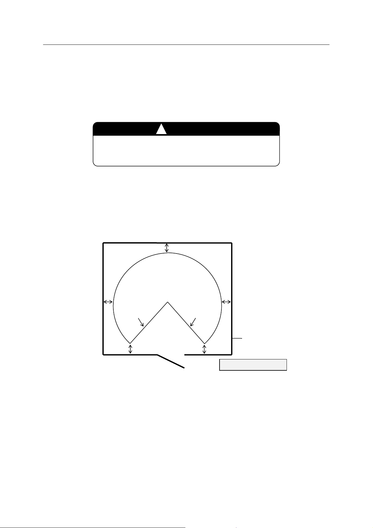
10. Outside the safety fence with margin (min. 1 m) from the motion range of robot arm (with tools
and workpieces).
The controller shall not be located inside of the robot’s
motion range/workcell/safety fence.
!
CAUTION
In addition, ensure the followings:
Enough space for easy access to the controller during maintenance
Installing an entrance gate with a safety plug to the safety fence
Referring the requirements established in each region for details of the safety fence
(e.g. ISO 13854-13855, ISO 13857, ISO 14119-14120 etc.)
Approx. 1 m
Approx. 1 m
Motion range of robot arm
(tool and workpiece included)
Mechanical
stopper
Mechanical
stopper
Approx. 1 m
Gate with safety plug
Approx.
1 m
Approx.
1 m
Safety fence
Controller
4

E5x Series Controller 1 Safety
Kawasaki Robot Installation and Connection Manual
1.3 Precautions When Connecting Harness
Strictly observe the following precautions when connecting the robot arm with the robot controller.
In order to prevent accidents caused by electric shock, do not connect the
external power until connections between the robot arm and robot controller
are complete.
1. Be careful when connecting the harnesses. Be sure to use the correct
harnesses. Using an incorrect harness, or forcing or misconnecting the
harness may damage connectors or cause a break in the electrical system.
2. Prevent people or equipment (forklift etc.) from stepping on or riding over
the signal and motor harnesses. Otherwise, the harness may become
damaged or the electrical system may break.
3. Separate the harnesses from any nearby high voltage lines (min. 1 m apart).
Do not bundle or run the harnesses in parallel with other power lines.
Otherwise, the noise generated from power lines will cause malfunctions.
4. Even when the harnesses are long, do not bundle them winded or bended.
Bundling the harness causes the heat to build up in the harness, resulting in
over-heat and furthermore may cause fire.
!
!
WARNING
CAUTION
5
E5x Series Controller 1 Safety
Kawasaki Robot Installation and Connection Manual
1.4 Precautions When Connecting the External Power
Strictly observe the following precautions when connecting the external power.
Before beginning the connection work, confirm that the external power supply for the
controller is cut off at the source. To prevent external power from being turned ON
accidentally, tag the breaker and indicate clearly that work is in progress. Or, assign a
supervisor in front of the breaker until all the connections are complete. Connecting
components while power is supplied is extremely dangerous and may cause electric
shock.
1. Confirm that the connected supplying power meets specifications shown on the
rating plate and the label attached on the side of the breaker. Supplying
out-of-specification power will damage electric components in the controller.
2. Ground the controller to prevent against electrical noise and shock.
3. Use dedicated groung wire (100 or less), which is equal to or larger than the
recommended power cable size (3.5 to 13 mm2).
4. Never share an ground line with workpiece to be welded or another machine (weld
machine, etc.).
5. In arc welding applications, connect the minus pole of the weld power supply to a
jig or directly to workpiece to be welded. Insulate the robot body and controller so
that they do not share a common ground line.
6. Without fail, before turning ON the external power to controller, make sure the
power supply wiring is complete and all the covers reattached properly. Otherwise,
failure to do so may cause electric shock.
!
!
DANGER
WARNING
6
E5x Series Controller 1 Safety
Kawasaki Robot Installation and Connection Manual
1. Prepare external power that meets the specifications of the controller in terms of
momentary power interruption, voltage fluctuation, power capacity, etc. If the
power is interrupted or the voltage goes out of the controller’s specified range
(above/below ratings), then the power monitoring circuit activates cutting off the
power, and an error is returned.
2. If the external power emits a lot of electrical noise, set up a noise filter to reduce
the interference.
3. PWM noise from robot motor lines may cause malfunction of low noise- resistant
devices via external power line. Confirm that there are no such devices in the
vicinity.
4. Install a separate external power switch (breaker) for the robot, independent and
unconnected to the weld machine.
5. To prevent shorting or accidental leakage on the external power switch, install a
ground leakage breaker. (Use a time delay type with sensitivity of 100 mA or
more.)
6. If there is a possibility that surge voltage such as lightning surge might be applied
from external power line, decrease the surge voltage level by mounting a surge
absorber.
!
CAUTION
NOTE* Proximity switch directly connected with power line etc. may suffer from the influence.
7
E5x Series Controller 1 Safety
p
Kawasaki Robot Installation and Connection Manual
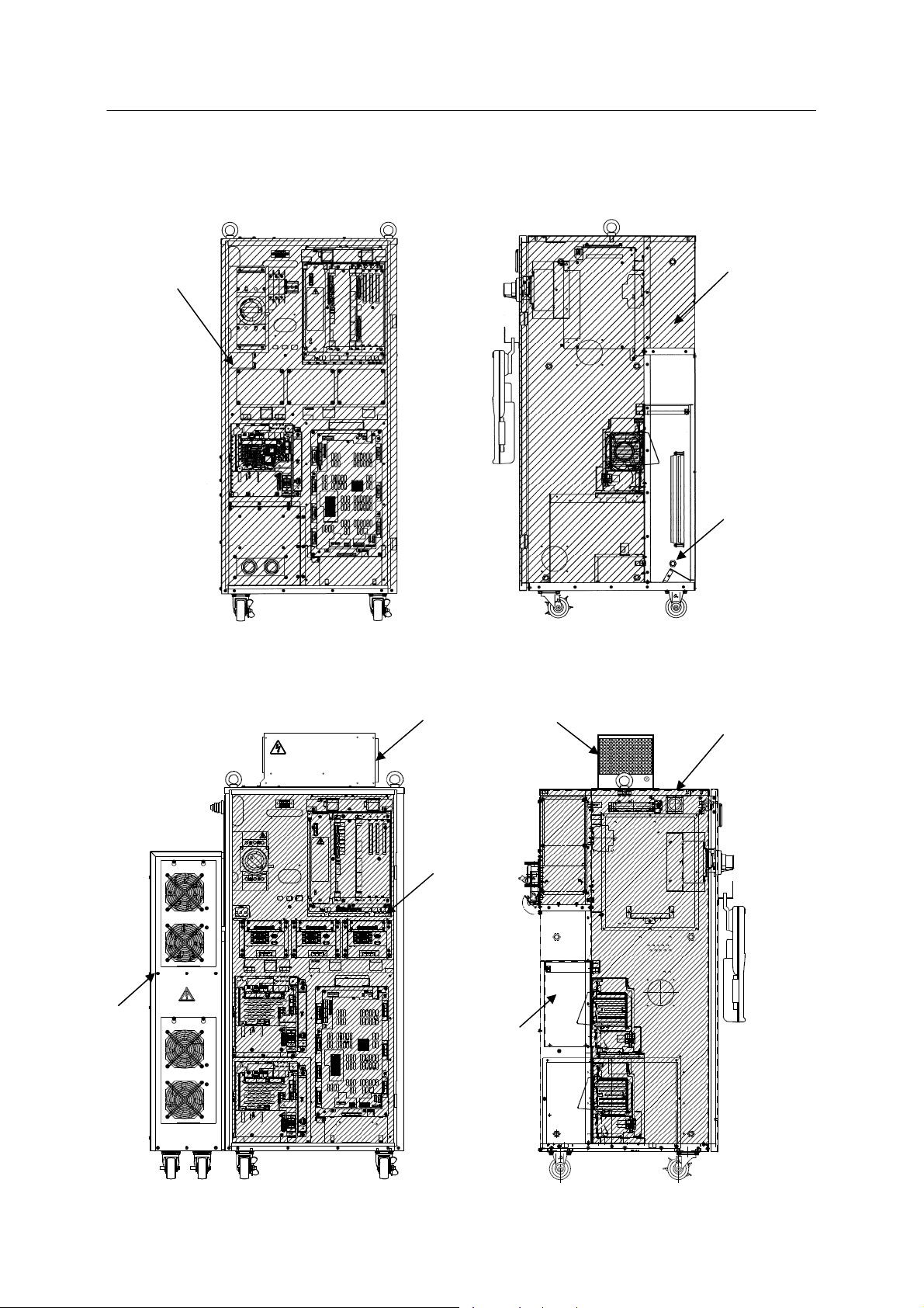
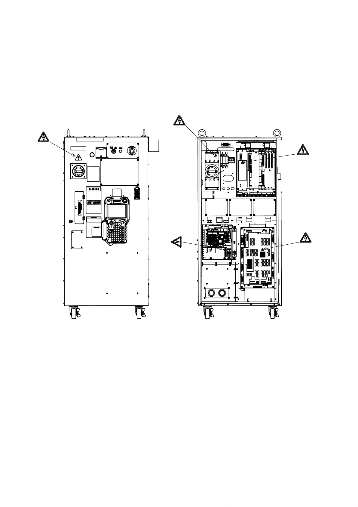
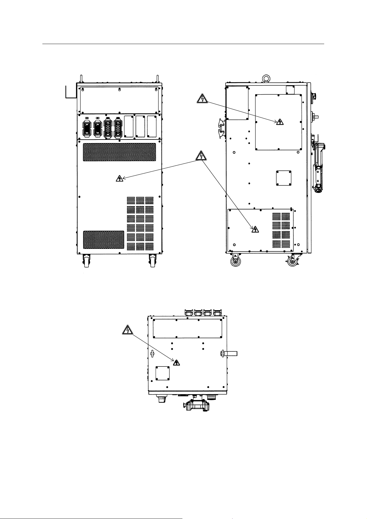
1.5 Warning Label for Electric Shock
Warning labels for electric shock are located on the controllers shown below.
E51 controller
Controller
ower switch
The terminals are alive even when the
controller power switch is OFF.
DC power
supply (AVR)
Front
Servo amplifier
Power unit
(Door omitted)
8
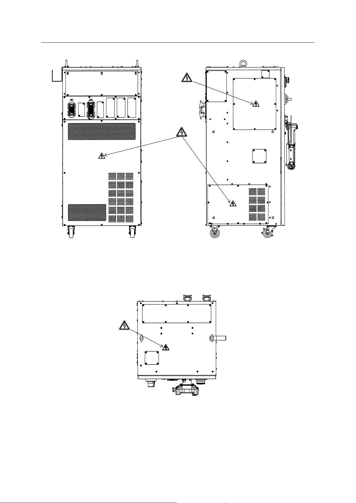
E5x Series Controller 1 Safety
Kawasaki Robot Installation and Connection Manual
Transformer
Rear
Breaker
Left
To p
9
E5x Series Controller 1 Safety
p
Kawasaki Robot Installation and Connection Manual
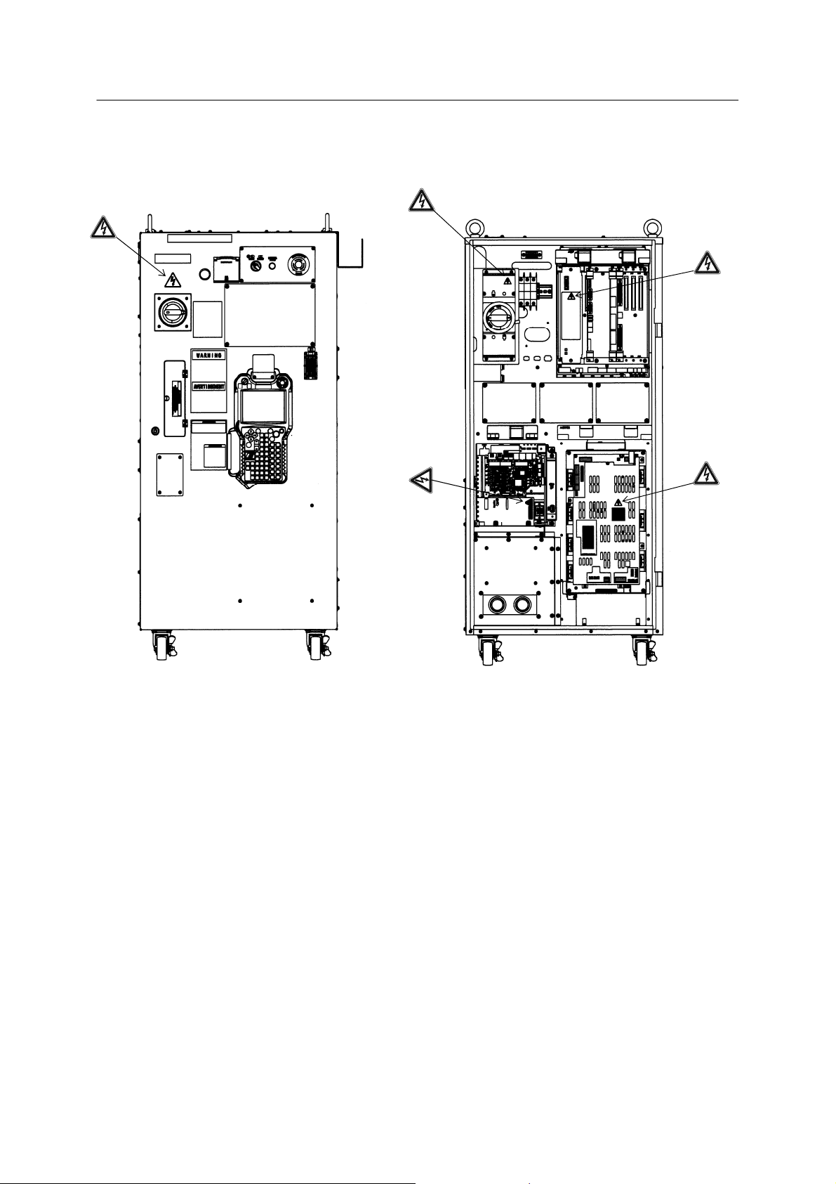
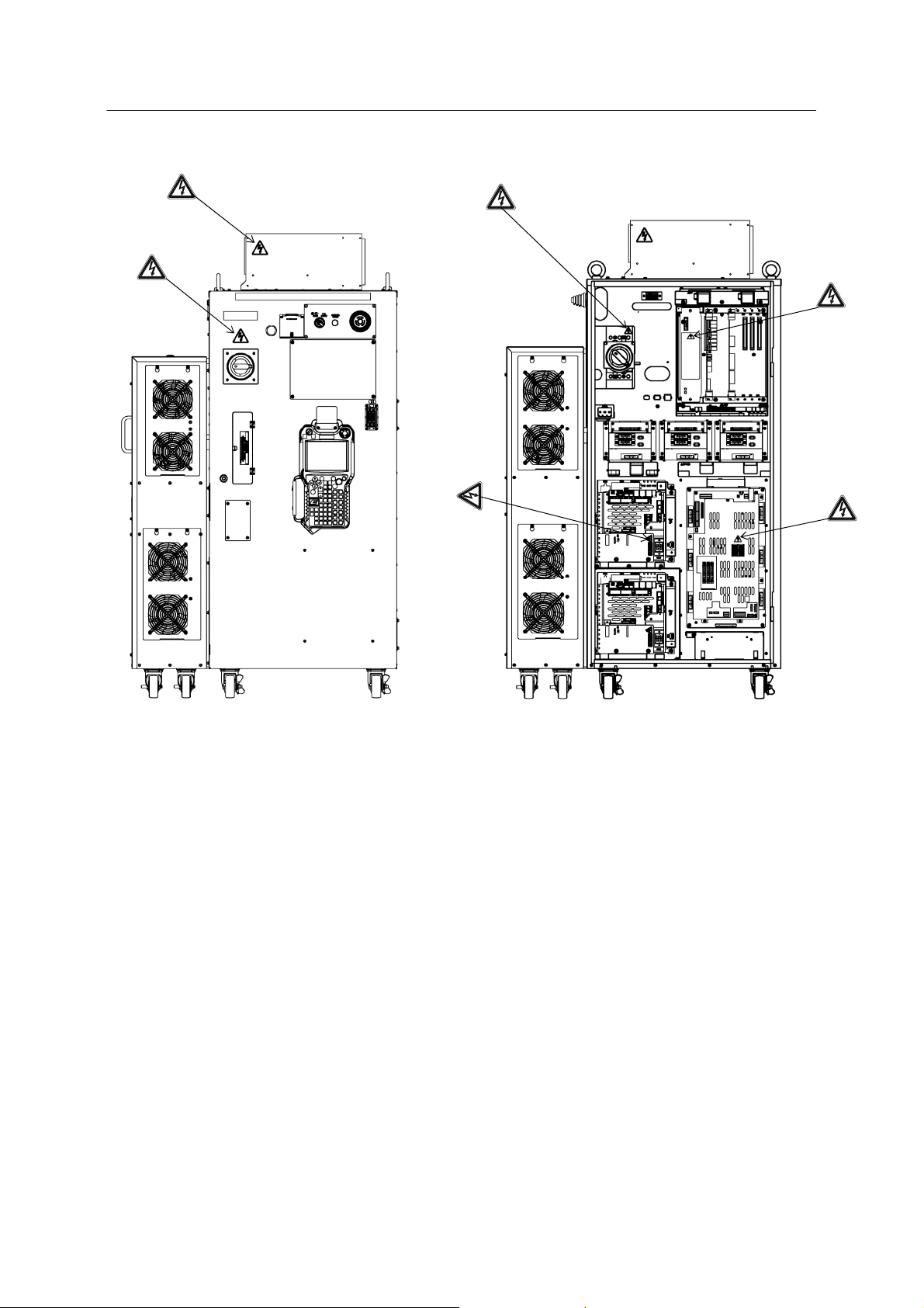
E52 controller
Controller
ower switch
Power unit
The terminals are alive even when the
controller power switch is OFF.
DC power
supply (AVR)
Servo amplifier
Front (Door omitted)
10

E5x Series Controller 1 Safety
Kawasaki Robot Installation and Connection Manual
Breaker
Rear
Transformer
Left
11
To p
E5x Series Controller 1 Safety
p
Kawasaki Robot Installation and Connection Manual
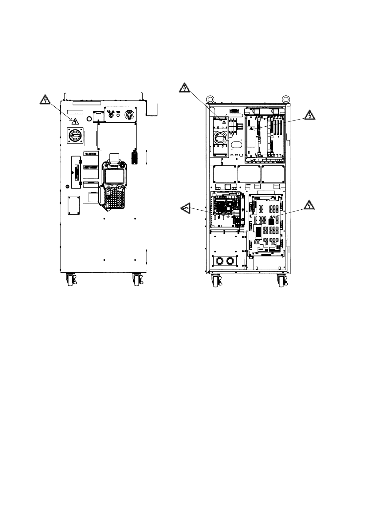
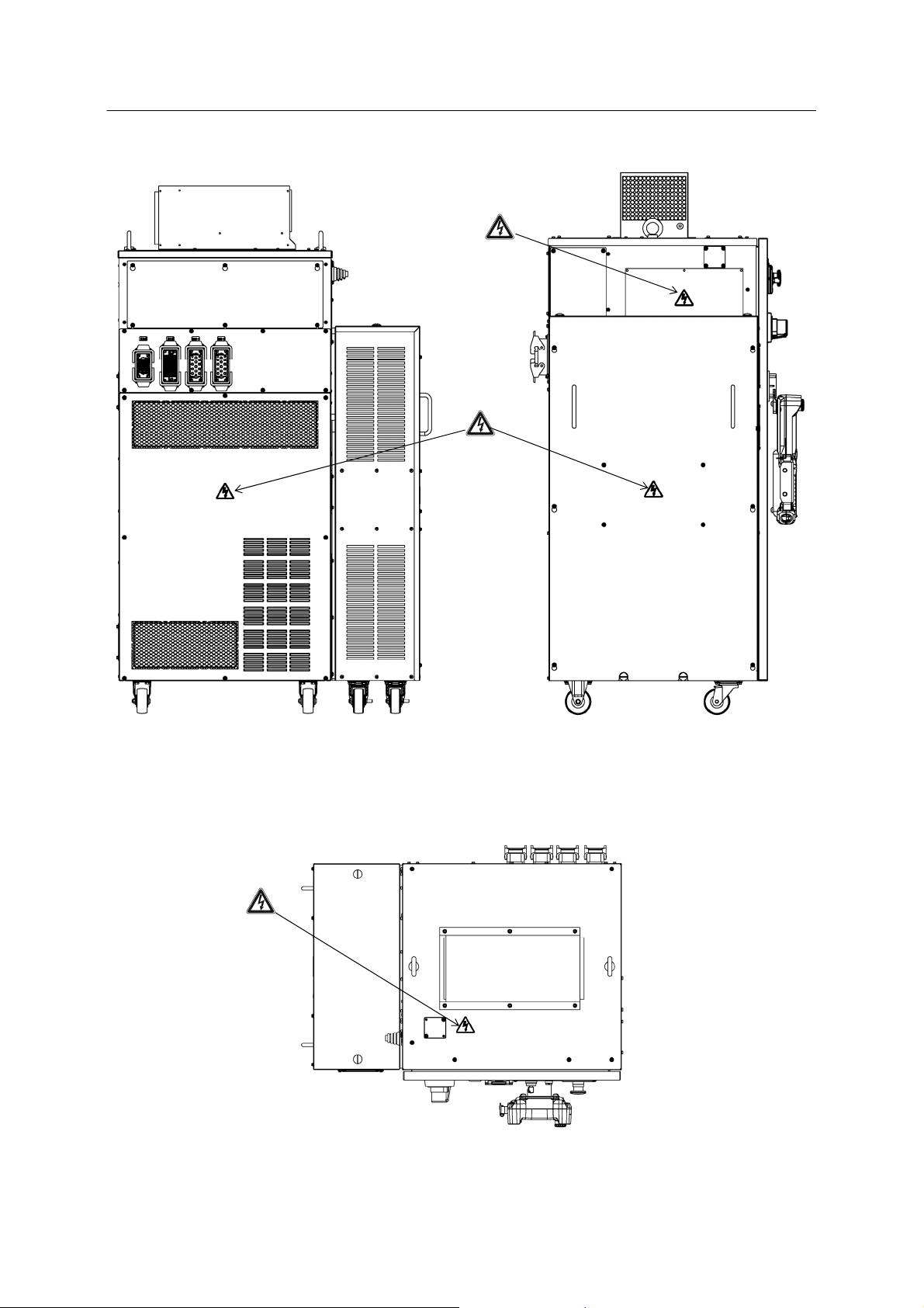
E54 controller
Controller
ower switch
The terminals are alive even when the
controller power switch is OFF.
Power unit
DC power
supply (AVR)
Servo amplifier
Front
(Door omitted)
12
E5x Series Controller 1 Safety
Kawasaki Robot Installation and Connection Manual
Breaker
Rear
Transformer
Left
13
To p
E5x Series Controller 1 Safety
p
Kawasaki Robot Installation and Connection Manual
E58 Controller
Heat
exchanger
Controller
ower switch
The terminals are alive even when the
controller power switch is OFF.
DC power
supply (AVC)
Power unit
Servo
amplifier
Front (Door omitted)
14
E5x Series Controller 1 Safety
Kawasaki Robot Installation and Connection Manual
Breaker
Transformer
Rear Left
Top
15
E5x Series Controller 1 Safety
Kawasaki Robot Installation and Connection Manual
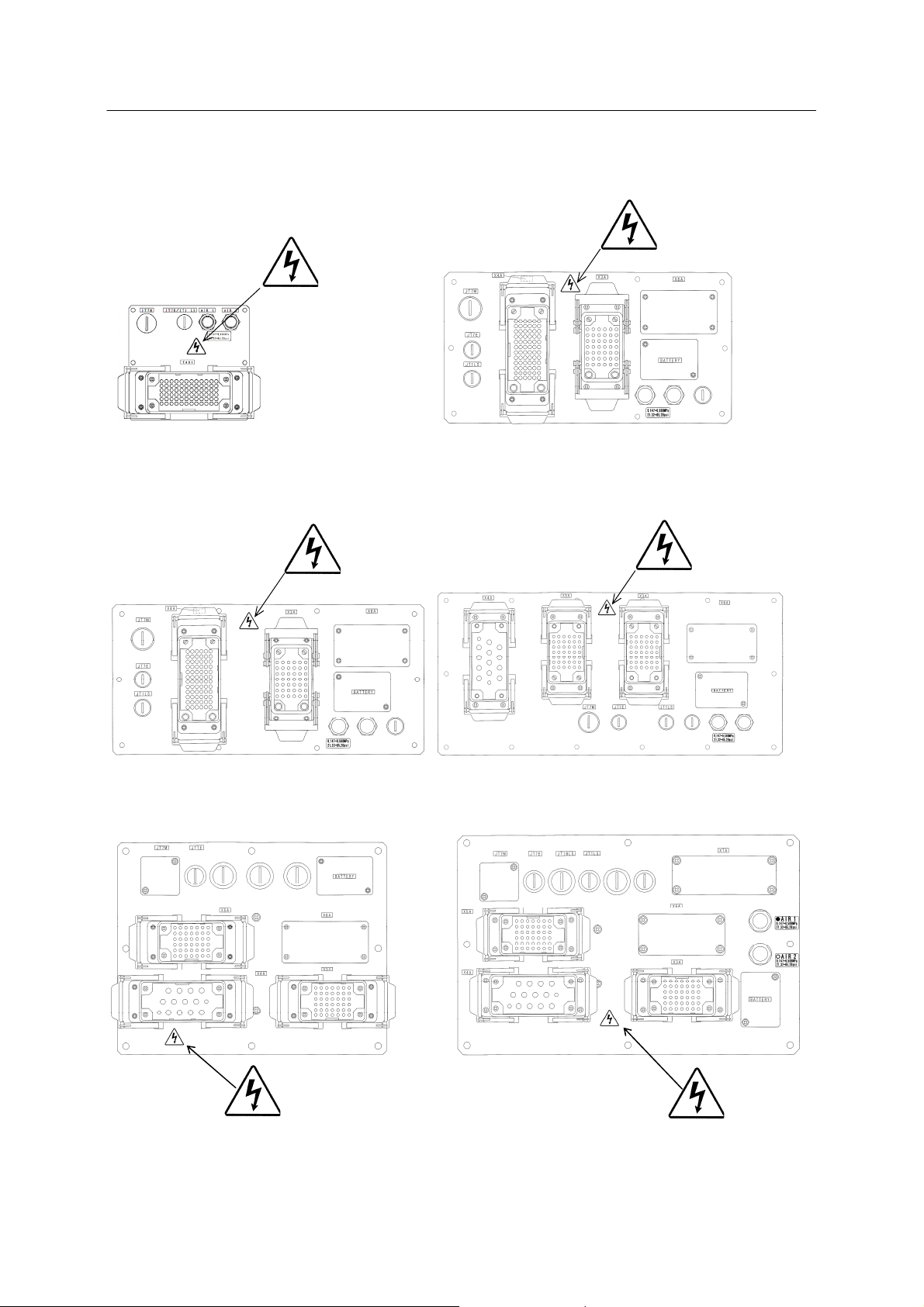
Connector plates on arm base section
R series 03N/05N/05L R series 10N/06L
R series 20N/10L R series 30N/50N/80N/15X
ZH
ZX/ZT
16
 Loading...