

Kawasaki Brute Force 750, KVF 750, BRUTE FORCE 750 4x4i, KVF 750 4x4 Service Manual

BRUTE FORCE 750 4×4i
Property of www.SmallEngineDiscount.com - Not for Resale
KVF 750 4×4
All Terrain Vehicle
Service Manual

Property of www.SmallEngineDiscount.com - Not for Resale
Quick R eference Guide
Property of www.SmallEngineDiscount.com - Not for Resale
General Information 1 j
Periodic Maintenance 2 j
Fuel System 3 j
Cooling System 4 j
Engine Top End 5 j
Converter System 6 j
Recoil Starter 7 j
Engine Lubrication System 8 j
This quick reference guide will assist
you in locating a desired topic or procedure.
•Bend the pages back to match the
black tab of the desired chapter number with the black tab on the edge at
each table of contents page.
•Referto the sectional table of contents
for the exact pages to locate the specific topic required.
Engine Removal/Installation 9 j
Crankshaft/Transmission 10 j
Wheels/Tires 11 j
Final Drive 12 j
Brakes 13 j
Suspension 14 j
Steering 15 j
Frame 16 j
Electrical System 17 j
Appendix 18 j

Property of www.SmallEngineDiscount.com - Not for Resale

BRUTE FORCE 750 4×4i
Property of www.SmallEngineDiscount.com - Not for Resale
KVF 750 4×4
All Terrain Vehicle
Service Manual
All r ights reserved. No parts of this publication may be reproduced, stored in a retrieval system, or
transmitted in any form or by any means, electronic mechanical photocopying, recording or otherwise,
without the prior written permission of Quality Assurance Department/Consumer Products & Machinery
Company/Kawasaki Heavy Industries, Ltd., Japan.
No liability can be accepted for any inaccuracies or omissions in this publication, although every possible
care has been taken to make it as complete and accurate as possible.
The right is reserved to make changes at any time without prior notice and without incurring an obligation
to make such changes to products manufactured previously. See your dealer for the latest information on
product improvements incorporated after this publication.
All information contained in this publication is based on the l atest product information available at the time
of publication. Illustrations and photographs in this publication are intended for reference use only and may
not depict actual model com ponent parts.
© 2004 Kawasaki Heavy Industries, Ltd. Second Edition (1) : Jul. 6, 2004

LIST OF ABBREVIATIONS
Property of www.SmallEngineDiscount.com - Not for Resale
A
ABDC after bottom dead center
AC alternating current min minute(s)
ATDC after top dead center N newton(s)
BBDC before bottom dead center Pa pascal(s)
BDC bottom dead center PS horsepower
BTDC before top dead center psi pound(s) per square inch
°C degree(s) Celcius r revolution
DC direct current rpm revolution(s) per minute
F farad(s) TDC top dead center
°F degree(s) Fahrenheit TIR total indicator reading
ft foot, feet V volt(s)
g gram(s) W watt(s)
h hour(s) Ω ohm(s)
L liter(s)
ampere(s)
lb
m
pounds(s)
meter(s)
Read OWNER’S MANUAL before operating.

EMISSION CONTROL INFORMATION
Property of www.SmallEngineDiscount.com - Not for Resale
Toprotecttheenvironment in which we alllive,Kawasakihasincorporatedcrankcaseemission
(1) and exhaust emission (2) control systems in compliance with applicable regulations of the
California Air Resources Board.
1. Crankcase Emission Control System
A sealed-type crankcase emission control system is used to eliminate blow-by gases. The blow
-by gases are led to the breather chamber through the crankcase. Then, it is led to the air cleaner.
Oil is separated from the gases while passing through the inside of the breather chamber from
the crankcase, and then returned back to the bottom of crankcase.
2. Exhaust Emission Control System
The exhaust emission control system applied to this engine family is engine modifications that
consist of a modified carburetor and an ignition system having optimum ignition timing characteristics.
The carburetor has been calibrated to provide lean air/fuel mixture characteristics and optimum
fuel economy with a suitable air cleaner and exhaust system.
A maintenance free ignition system provides the most favorable ignition timing and helps main-
tain a thorough combustion process within the engine which contributes to a reduction of exhaust
pollutants entering the atmosphere.
The Clean Air Act, which is the Federal law covering motor vehicle pollution, contains what is
commonly referred to as the Act’s "tampering provisions."
"Sec. 203(a) The following acts and the causing thereof are prohibited...
(3)(A) for any person to remove or render inoperative any device or element of design installed
on or in a motor vehicle or motor vehicle engine in compliance with regulations under this
title prior to its sale and delivery to theultimate purchaser, or for any manufacturer or dealer
knowingly to remove or render inoperative any such device or element of design after such
sale and delivery to the ultimate purchaser.
(3)(B) for any person engaged in the business of repairing, servicing, selling, leasing, or trading
motor vehicles or motor vehicle engines, or who operates a fleet of motor vehicles knowingly to remove or render inoperative any device or element of design installed on or in a
motor vehicle or motor vehicle engine in compliancewith regulations under this title f ollowing its sale and delivery to the ultimate purchaser..."
NOTE
The phrase "remove or render inoperative any device or element of design" has been generally
○
interpreted a s follows:
1. Tampering does not include the temporary removal or rendering inoperative of devices or elements of design in order to perform maintenance.
2. Tampering could include:
a.Maladjustment of vehicle components such that the emission standards are ex-
ceeded.
b.Use of replacement parts or accessories which adversely affect the performance
or durability of the vehicle.
c.Addition of components or accessories that resultinthevehicleexceedingthe stan-
dards.
d.Permanently removing, disconnecting, or rendering inoperative any component or
element of d esign of the emission control systems.
WE RECOMMEND THAT ALL DEALERS OBSERVE THESE PROVISIONS OF FEDERAL LAW,
THEVIOLATIONOFWHICHISPUNISHABLEBYCIVILPENALTIESNOTEXCEEDING
$10,000 PER VIOLATION.

PLEASE DO NOT TAMPER WITH NOISE CONTR OL SYSTEM
Property of www.SmallEngineDiscount.com - Not for Resale
(US MODEL only)
To minimize the noise emissions from this product, Kawasaki has equipped it with effective
intake and exhaust silencing systems. They are designed to give optimum performance while
maintaining a low noise level. Please do not remove these systems, or alter them in any which
results in an increase in noise level.
Foreword
Property of www.SmallEngineDiscount.com - Not for Resale
This manual is designed primarily for use by
trained mechanics in a properly equipped shop.
However,it contains enoughdetailand basic informationto make it useful to theownerwhodesirestoperform his own basic maintenance and
repair work. A basic knowledge of mechanics,
the proper use of tools, and workshop procedures must be understood in order to carry out
maintenance and repair satisfactorily. Whenever the owner has insufficient experience or
doubts his ability to do the work, all adjustments, maintenance, and repair should be carried out only by qualified mechanics.
In order to perform the work efficiently and
to avoid costly mistakes, read the text, thoroughly familiarize yourself with the procedures
beforestartingwork, and then do the work carefully in a clean area. Whenever special tools or
equipment are specified, do not use makeshift
tools or equipment. Precision measurements
can only be made if the proper instruments are
used, and the use of substitute tools may adversely affect safe operation.
For the duration of the warranty period,
we recommend that all repairs and scheduled
maintenance be performed in accordance with
thisservice manual. Anyowner maintenance or
repair procedure not performed in accordance
with this manual may void the warranty.
To get the longest life out of your vehicle:
Follow the Periodic M aintenance Chart in the
•
Service Manual.
Be alert for problems and non-scheduled
•
maintenance.
Use proper toolsand genuineKawasaki Vehi-
•
cle parts. Special tools, gauges, and testers
that are necessary when servicing Kawasaki
vehicles are introduced by the Special Tool
Catalog or Manual. Genuine parts provided
as spare parts are listed in the Parts Catalog.
Follow the procedures in this manual care-
•
fully. Don’t take shortcuts.
Rememberto keep completerecordsof main-
•
tenance and repair with dates and any new
parts installed.
How to Use This Manual
In this manual, the product is divided into
its major systems and these systems make up
the manual’s chapters. The Quick Reference
Guide shows you all of the product’s system
and assists in locating their chapters. Each
chapter in turn has its own comprehensive Table of Contents.
For example, if you want ignitioncoil information, use the Quick Reference Guide to locate
the Electrical System chapter. Then, use the
Table of Contents on the first page of the chapter to find the Ignition Coil section.
Whenever you see these WARNING and
CAUTION symbols, heed their instructions!
Always follow safe operating and maintenance
practices.
WARNING
This warning symbol identifies special
instructions or procedures which, if not
correctly followed, could result in per-
sonal injury, or loss of life.
CAUTION
This caution sym bol identifies special
instructions or procedures which, if not
strictly observed, could result in dam-
age to or destruction of equipment.
This m anual contains four more symbols (in
additionto WARNINGand CAUTION)whichwill
help you distinguish different types of information.
NOTE
This note symbol indicates points of par-
○
ticular interest for more efficient and con-
venient operation.
Indicates a procedural step or work to be
•
done.
Indicates a procedural sub-step or how to do
○
the work of the procedural step it follows. It
also precedes the text of a NOTE.
Indicates a conditional step or what action to
takebasedon the results ofthetestor inspec-
tion in the procedural step or sub-step it fol-
lows.
In most chapters an exploded view illustration
of the system components follows the Table of
Contents. In these illustrations you will find the
instructionsindicating which parts require specified tightening torque, oil, grease or a locking
agent during assembly.

Property of www.SmallEngineDiscount.com - Not for Resale

GENERAL INFORMATION 1-1
Property of www.SmallEngineDiscount.com - Not for Resale
General Information
Table of Contents
Before Servicing..................................................................................................................... 1-2
Model Identification................................................................................................................. 1-7
General Specifications............................................................................................................ 1-8
Unit Conversion Table ............................................................................................................ 1-11
1

1-2 GENERAL INFORMATION
Property of www.SmallEngineDiscount.com - Not for Resale
Before Servicing
Before starting to perform an inspection service or carry out a disassembly and reassembly operation on a vehicle, read the precautions given below. To facilitate actual operations, notes, illustrations, photographs, cautions, and detailed descriptions have been included in each chapter wherever
necessary. This section explains the items that require particular attention during the removal and
reinstallation or disassembly and reassembly of general parts.
Especially note the following:
Battery Ground
Before completing any service on the vehicle, disconnect
thebatterywires from the battery topreventtheengine from
accidentally turning over. Disconnect the ground wire (–)
first and then the positive (+). When completed with the
service, first connect the positive (+) wire to the positive
(+) terminal of the battery then the negative (–) wire to the
negative terminal.
Edges of Parts
Lift large or heavy parts wearing gloves to prevent injury
from possible sharp edges on the parts.
Solvent
Use a high-flush point solvent when cleaning parts. High
-flush point solvent should be used according to directions
of the solvent manufacturer.
Cleaning vehicle before disassembly
Clean the vehicle thoroughly before disassembly. Dirt or
otherforeign materials enteringintosealed areas during vehicle disassembly can causeexcessive wear and decrease
performance of the vehicle.

Before Servicing
Property of www.SmallEngineDiscount.com - Not for Resale
Arrangement and Cleaning of Removed Parts
Disassembled parts are easy to confuse. Arrange the
parts according to the order the parts were disassembled
and clean the parts in order prior to assembly.
Storage of Removed Parts
After all the parts includingsubassembly parts have been
cleaned, store the parts in a clean area. Put a clean cloth
or plastic sheet over the parts to protect from any foreign
materials that may collect before re-assembly.
GENERAL INFORMATION 1-3
Inspection
Reuse of worn or damaged parts may lead to serious accident. Visually inspect removed parts for corrosion, discoloration, or otherdamage. Refer to the appropriate sections
of this manual for service limits on individual parts. Replace
the parts if any damage has been found or if the part is beyond its service limit.
Replacement Parts
Replacement Parts must be KAWASAKI genuine or
recommended by KAWASAKI. Gaskets, O-rings, Oil seals,
Grease seals, circlips or cotter pins must be replaced with
new ones whenever disassembled.
Assembly Order
In most cases assembly order is the reverse of disassembly, however, if assembly order is provided in this Service
Manual, follow the procedures given.

1-4 GENERAL INFORMATION
Property of www.SmallEngineDiscount.com - Not for Resale
Before Servicing
Tightening Sequence
Generally, when installing a part with several bolts, nuts,
or screws, start them all in their holes and tighten them to
a snug fit. Then tighten them according to the specified sequence to prevent case warpage or deformation which can
lead to malfunction. Conversely when loosening the bolts,
nuts, or screws, first loosen all of them by about a quarter turn and then remove them. If the specified tightening
sequence is not indicated, tighten the fasteners alternating
diagonally.
Tightening Torque
Incorrect torque applied to a bolt, nut, or screw may
lead to serious damage. Tighten fasteners to the specified
torque using a good quality torque wrench.
Often, the tightening sequence is f ollowed twice initial
tightening and final tightening with torque wrench.
Force
Use common sense during disassembly and assembly,
excessiveforcecan cause expensive or hard to repair damage. When necessary, remove screws that have a non
-permanent locking agent applied using an impact driver.
Use a plastic-faced mallet whenever tapping is necessary.
Gasket, O-ring
Hardening, shrinkage, or damage of both gaskets
and O-rings after disassembly can reduce sealing performance. Remove old gaskets and clean the sealing
surfaces thoroughly so that no gasket material or other
material remains. Install new gaskets and replace used
O-rings when re-assembling.
Liquid Gasket, Locking Agent
For applications that require Liquid Gasket or a
Non-Permanent Locking Agent, clean the surfaces so
that no oil residue remains before applying liquid gasket
or locking agent. Do not apply them excessively. Excessive application can clog oil passages and cause serious
damage.
Before Servicing
Property of www.SmallEngineDiscount.com - Not for Resale
Press
For items such as bearings or oil seals that must be
pressed into place, apply small amount of oil to the contact area. Be sure to maintain proper alignment and use
smooth movements when installing.
Ball Bearing and Needle Bearing
Do not remove pressed ball or needle unless removal is
absolutely necessary. Replace with new ones whenever
removed. Press bearings with the manufacturer and size
marks facing out. Press the bearing into place by putting
pressure on the correct bearing race as shown.
Pressing the incorrect race can cause pressure between
the inner and outer race and result in bearing damage.
GENERAL INFORMATION 1-5
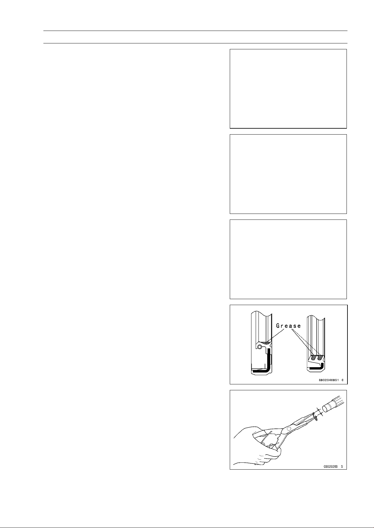
Oil Seal, Grease Seal
Donot remove pressedoil or greasesealsunless removal
is necessary. Replace with new ones whenever removed.
Press new oil seals with manufacture and size marks facing
out. Make sure the seal is aligned properly when installing.
Apply specified grease to the lip of seal before installing
the seal.
Circlips, Cotter Pins
Replacecirclips orcotterpins thatwere removed withnew
ones. Take care not to open the clip excessively when installing to prevent deformation.

1-6 GENERAL INFORMATION
Property of www.SmallEngineDiscount.com - Not for Resale
Before Servicing
Lubrication
It is important to lubricate rotating or sliding parts during
assembly to minimize wear during initial operation. Lubrication points are called out throughout this manual, apply
the specific oil or grease as specified.
Direction of Engine Rotation
When rotating the crankshaft by hand, the free play
amount of rotating direction will affect the adjustment. Rotate the crankshaft to positive direction (clockwise viewed
from output side).
Electrical Wires
A two-color wire is identified firstby the primary color and
then the stripe color. Unless instructedotherwise, electrical
wires must be connected to those of the same color.

Model Identification
Property of www.SmallEngineDiscount.com - Not for Resale
KVF750-A1 Left Side View
GENERAL INFORMATION 1-7
KVF750-A1 Right Side View
The KVF750–B1 is a camouflage-surface-treated model and identical to the KVF750–A1, the base
model, in every other aspect: controls, features, and specifications.

1-8 GENERAL INFORMATION
Property of www.SmallEngineDiscount.com - Not for Resale
General Specifications
Items KVF750-A1, B1
Dimensions
Overall Length 2 192 mm (86.30 in.)
Overall Width 1 177 mm (46.34 in.)
Overall Height 1 249 mm (49.17 in.)
Wheelbase 1 283 mm (50.51 in.)
Ground Clearance: 269 mm (10.59 in.)
Seat Height 935 mm (36.81 in.)
Dry Mass 274 kg (604 lb), (EUR) 274.5 kg (605 lb)
Curb Mass:
Front 147.5 kg (325 lb), (EUR) 148 kg (326 lb)
Rear 149 kg (329 lb)
Fuel Tank Capacity 19.5 L (5.2 US gal)
Performance
Minimum Turning Radius 3.2 m (10.5 ft)
Engine
Type 4-stroke, SOHC, V2-cylinders
Cooling System Liquid-cooled
Bore and Stroke 85 × 66 mm (3.35 × 2.60 in.)
Displacement 749 mL (45.7 cu in.)
Compression Ratio 8.8 : 1
Maximum Horsepower 37.4 kW (50.9 PS) @6 500 r/min (rpm), (US) Maximum Torque 60.7 N·m (6.2 kgf·m, 45 ft·lb) @5 000 r/min (rpm)
Carburetion System Carburetor, Keihin CVKR-34
Starting System Electric Starter & Recoil Starter
Ignition System Digital DC-CDI
Timing A dvance Electronically advanced
Ignition Timing From 5° BTDC @1 150 r/min (rpm)
to 28° BTDC @5 000 r/min (rpm)
Spark Plug NGK CR7E, DENSO U22ESR-N
Cylinder Numbering Method Front to rear, 1-2
Firing Order 1-2
Valve Timing:
Inlet:
Open 20° BTDC
Close 44° ABDC
Duration 244°
Exhaust:
Open 44° BBDC
Close 20° ATDC
Duration 244°
Lubrication Aystem Forced lubrication (wet sump)

General Specifications
Property of www.SmallEngineDiscount.com - Not for Resale
Items KVF750-A1, B1
Engine oil:
Type
Viscosity SAE 10W-40
Capacity 2.6 L (2.75 US qt)
Drive Train
Primary Reduction System:
Type Belt converter
Reduction Ratio 3.122 ∼ 0.635
Transmission:
Type 2-speed and reverse
Gear Ratios:
Forward:
High
Low
Reverse 4.028 (16/12 × 18/16 × 29/18 × 20/12)
Final Drive System:
Type Shaft 2WD/4WD
Reduction Ratio 4.375 (35/8)
Overall Drive Ratio:
Forward:
High 42.32 ∼ 8.61
Low 66.02 ∼ 13.43
Reverse 55.01 ∼ 11.19
Front Final Gear Case Oil:
Type API SF or SG
Viscosity SAE10W-40
Capacity 0.40 L (0.42 US qt)
Rear Final Gear Case Oil:
Type
Capacity 0.72 L (0.76 US qt)
Frame
Type Double tubular
Caster (Rake Angle) 5.5°
Camber 0°
King Pin Angle 11°
Trail 28 mm (1.10 in.)
Tread:
Front 915 mm (36.23 in.)
Rear 875 mm (34.45 in.)
API SF or SG
API SH or SJ with JASO MA class
3.098 (30/26 × 29/18 × 20/12)
4.833 (36/20 × 29/18 × 20/12)
API SH or SJ with JASO MA class
MOBIL FLUID 424, CITGO TRANSGARD TRACTOR
HYDRAULIC FLUID, or EXXON HYDRAUL 560
GENERAL INFORMATION 1-9

1-10 GENERAL INFORMATION
Property of www.SmallEngineDiscount.com - Not for Resale
General Specifications
Items KVF750-A1, B1
Front tire:
Type Tubeless
Size AT25 × 8 – 12
Rear tire:
Type Tubeless
Size AT25 × 10 – 12
Suspension:
Front:
Type Double Wishbone
Wheel Travel 171 mm (6.73 in.)
Rear:
Type Double Wishbone
Wheel Travel 200 mm (7.87 in.)
Brake:
Front Disc × 2
Rear Enclosed wet multi-plate
Parking Brake Enclosed wet multi-plate
Electrical Equipment
Battery 12 V 12 Ah
Headlight:
Type Semi-sealed beam
Bulb 12 V 40/40 W × 2
Tail/brake Light:
Bulb 12 V 5/21 W
Reverse Light:
Bulb
Alternator:
Type Three - phase AC
Rated Output 24.2 A, 14 V @6 000 r/min (rpm)
(EUR) 12V 10W
Specifications are subject to change without notice, and may not apply to every country.
US: United States Model
EUR: Europe Model
Unit Conversion Table
Property of www.SmallEngineDiscount.com - Not for Resale
GENERAL INFORMATION 1-11
Prefixes for Units:
Prefix Symbol
mega M × 1 000 000
kilo k × 1 000
centi c ×0.01
milli m × 0.001
micro µ × 0.000001
Power
Units of Mass:
kg ×2.205=lb
g × 0.03527 = oz
Units of Volume:
L × 0.2642 = gal (US)
L × 0.2200 = gal (imp)
L×1.057=
L × 0.8799 =
L × 2.113 = pint (US)
L × 1.816 = pint (imp)
mL × 0.03381 = oz (US)
mL × 0.02816 = oz (imp)
mL × 0.06102 = cu in
qt (US)
qt (imp)
Units of Length:
km × 0.6214 = mile
m × 3.281 = ft
mm × 0.03937 = in
Units of Torque:
N·m × 0.1020 =
N·m × 0.7376 = ft·lb
N·m × 8.851 = in·lb
kgf·m × 9.807 = N·m
kgf·m × 7.233 = ft·lb
kgf·m
× 86.80 = in·lb
kgf·m
Units of Pressure:
kPa × 0.01020 = kgf/cm²
kPa × 0.1450 = psi
kPa × 0.7501 = cmHg
kgf/cm² × 98.07 = kPa
kgf/cm²
cmHg × 1.333 = kPa
× 14.22 = psi
Units of Speed:
km/h
× 0.6214 = mph
Units of Force:
N × 0.1020 = kg
N × 0.2248 = lb
kg ×9.807=N
kg ×2.205=lb
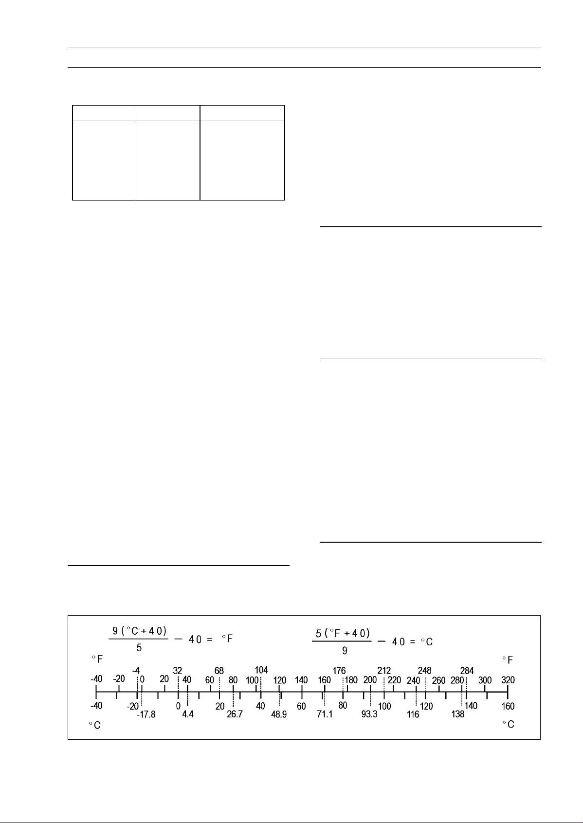
Units of Temperature
Units of Power:
kW × 1.360 =
kW × 1.341 = HP
PS × 0.7355 = kW
PS × 0.9863 = HP
PS

Property of www.SmallEngineDiscount.com - Not for Resale

PERIODIC MAINTENANCE 2-1
Property of www.SmallEngineDiscount.com - Not for Resale
Periodic Maintenance
Table of Contents
Periodic Maintenance Chart.............. 2-3
Torque and Locking Agent................. 2-5
Specifications .................................... 2-11
Special Tools ..................................... 2-13
Periodic Maintenance Procedures..... 2-14
Fuel System.................................... 2-14
Throttle Lever Free Play
Inspection.................................. 2-14
Throttle Lever Free Play
Adjustment ................................ 2-14
Choke Lever Free Play
Inspection.................................. 2-14
Choke Lever Free Play
Adjustment ................................ 2-15
Idle Speed Inspection .................. 2-15
Idle Speed Adjustment................. 2-16
Fuel System Cleanliness
Inspection.................................. 2-16
Air Cleaner Element Cleaning and
Inspection.................................. 2-17
Air Cleaner Draining..................... 2-17
Fuel Hose and Connection
Inspection.................................. 2-18
Fuel Hose Replacement .............. 2-18
Cooling System............................... 2-19
Radiator Cleaning ........................ 2-19
Radiator Hose and Connection
Inspection.................................. 2-20
Coolant Change........................... 2-20
Engine Top End .............................. 2-23
Valve Clearance Inspection ......... 2-23
Valve Clearance Adjustment........ 2-24
Spark Arrester Cleaning............... 2-24
Converter System........................... 2-25
Drive Belt Inspection.................... 2-25
Drive Belt Deflection Inspection... 2-25
Drive Belt Deflection Adjustment. 2-26
Actuator Lever (Engine Brake
Control Lever) Assembly
Inspection.................................. 2-27
Engine Lubrication System............. 2-27
Engine Oil Change....................... 2-27
Oil Filter Replacement ................. 2-28
Wheels/Tires................................... 2-28
Tire Inspection ............................. 2-28
Final Drive....................................... 2-29
2
Variable Differential Control Lever
Play Inspection.......................... 2-29
Variable Differential Control Lever
Play Adjustment........................ 2-29
Front Final Gear Case Oil
Change...................................... 2-30
Rear Final Gear Case Oil Change 2-31
Universal Joint Lubrication........... 2-32
Brakes............................................. 2-32
Front Brake Pad Wear Inspection 2-32
Front Brake Hoses and
Connections Inspection............. 2-32
Front Brake Hose Replacement... 2-33
Brake Fluid Level Inspection........ 2-33
Brake Fluid Change..................... 2-34
Front Brake Master Cylinder
Piston Assembly and Dust Seal
Replacement............................. 2-34
Front Brake Caliper Piston Seal
and Dust Seal Replacement ..... 2-34
Rear Brake Plates Replacement.. 2-35
Rear Brake Lever Free Play
Inspection.................................. 2-35
Brake Pedal Free Play Inspection 2-35
Rear Brake Lever and Pedal Free
Play Adjustment........................ 2-35
Steering.......................................... 2-36
Steering Inspection...................... 2-36
Electrical System............................ 2-36
Spark Plug Cleaning/Inspection... 2-36
Spark Plug Gap Inspection.......... 2-36
Brake Light Switch Inspection...... 2-37
Brake Light Timing Adjustment.... 2-37
Drive Belt Failure Detection
System Inspection..................... 2-37
Joint Boots Inspection..................... 2-39
Front Axle/Knuckle Joint Boot
Inspection.................................. 2-39
Front Propeller Shaft Boot
Inspection.................................. 2-39
Tie-rod End Boot Inspection ........ 2-39
Rear Propeller Shaft Joint Boot
Inspection.................................. 2-39
Rear Axle/Stabilizer Joint Boot
Inspection.................................. 2-39
General Lubrication ........................ 2-40

2-2 PERIODIC MAINTENANCE
Property of www.SmallEngineDiscount.com - Not for Resale
Lubrication................................... 2-40
Bolts and Nuts Tightening............... 2-41
Tightness Inspection.................... 2-41
PERIODIC MAINTENANCE 2-3
Property of www.SmallEngineDiscount.com - Not for Resale
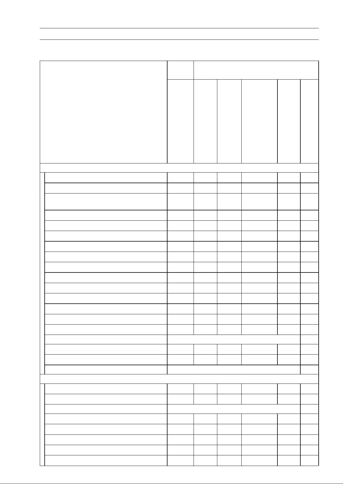
Periodic Maintenance Chart
The scheduled maintenancemust be done in accordance with t his chart to keep the vehicle in good
running condition. The initial maintenance is vitally important and must not be neglected.
FirstFREQUENCY
Service
Every
After 10
hrs. or
100 km
(60 mi.)
of use
OPERATION
ENGINE
Converter drive belt wear - inspect *
Converter drive belt deflection - inspect *
Drive belt failure detection system function
-inspect*
Engine brake control lever - inspect *
Air cleaner - inspect *
Throttle lever play - i nspect
Choke lever play - inspect
Idle speed - inspect
Valve clearance - inspect
Fuel system cleanliness - inspect *
Engine oil - change *
Oil filter - replace *
Spark plug - clean and gap
Spark arrester - clean
Fuel hoses and connections - inspect
Fuel hose - replace 4 years 2-18
• •
• •
• •
• •
• •
• •
• •
10
daysor
200km
(120
mi.) of
use
Regular Service
days, 1 700
Every
30
days or
600 km
(360
mi.) of
use
km (1 100
when belt
light turns
hrs of use)
whichever
comes first
•
Every 90
mi.) or
indicator
on (100
•
•
•
•
•
Every
year of
use
•
•
See
page
2-25
2-25
2-37
2-27
2-17
2-14
2-14
2-15
2-23
2-16
2-27
2-28
2-36
2-24
2-18
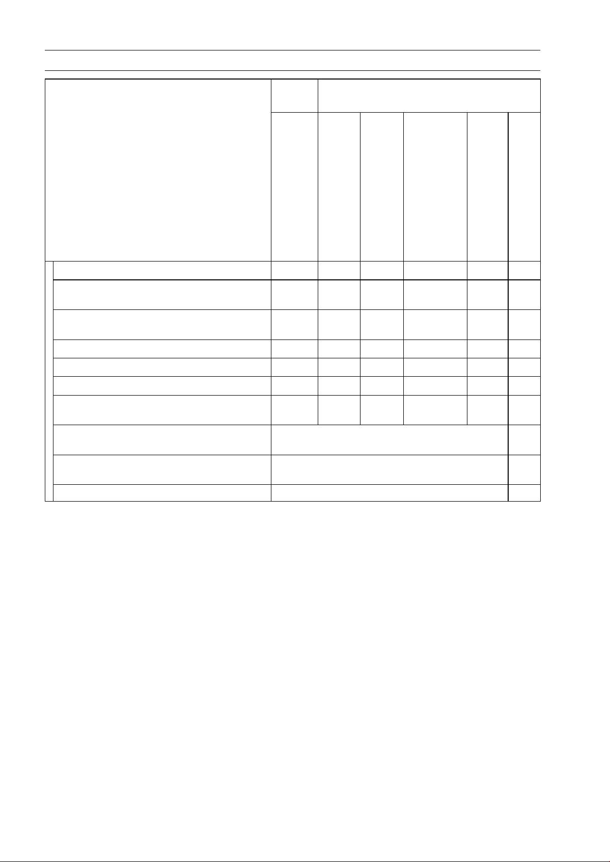
Radiator - clean*
Radiator hoses and connections - check*
Coolant - change*
CHASSIS
Joint boots - inspect *
Rear brake pedal and lever play - inspect *
Rear brake plates - replace * every 10 000 km (6 000 mi.) 2-35
Bolts and nuts - tighten
Front brake pad wear - inspect *
Brake light switch - inspect *
Steering - inspect
Differential control lever play - inspect
• •
2 years 2-20
• •
• •
• •
• •
• •
• •
• •
2-19
2-20
•
2-39
2-35
2-41
2-32
2-37
2-36
2-29
2-4 PERIODIC MAINTENANCE
Property of www.SmallEngineDiscount.com - Not for Resale
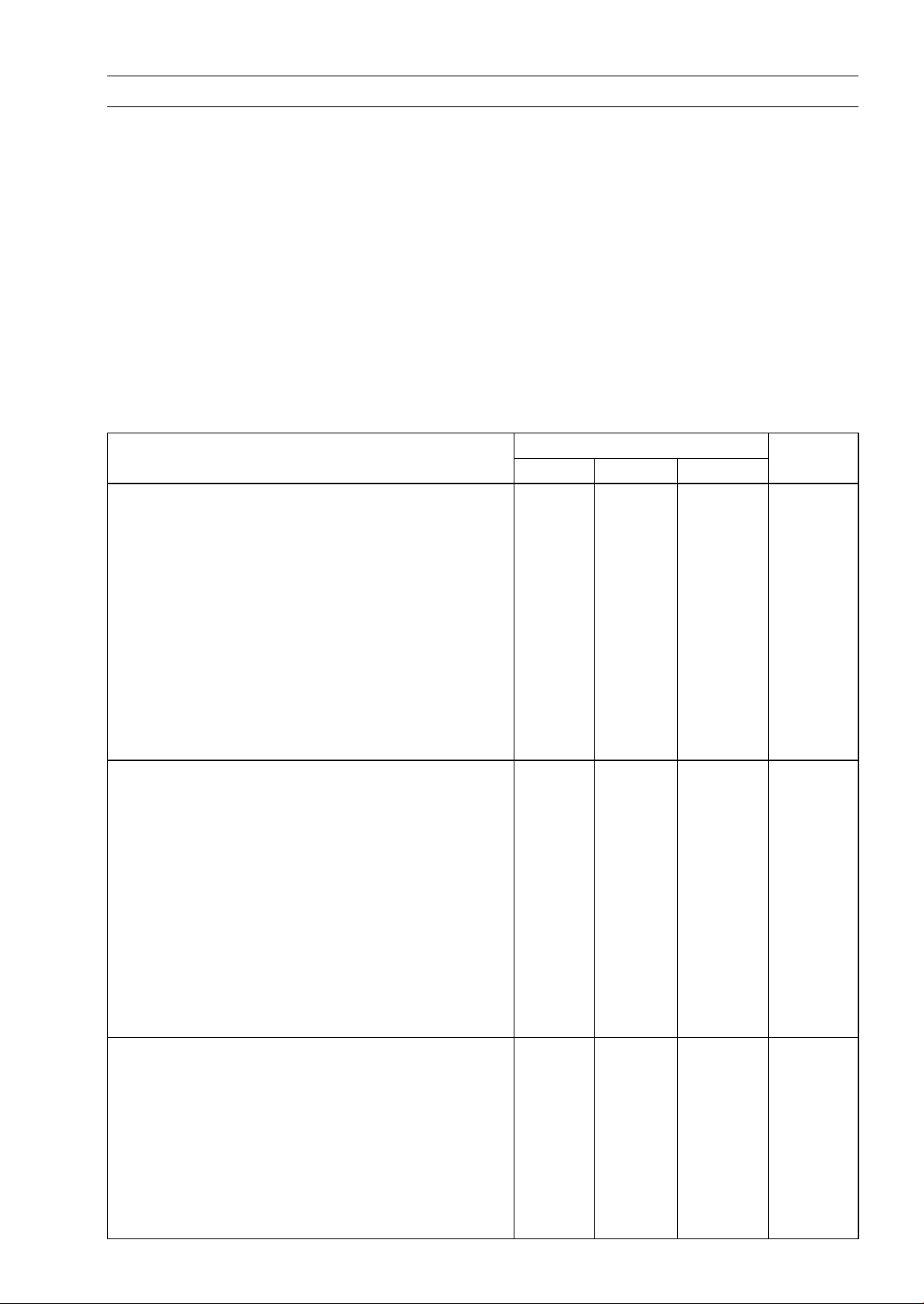
Periodic Maintenance Chart
FirstFREQUENCY
Service
Every
After 10
hrs. or
100 km
(60 mi.)
of use
OPERATION
Tire wear - inspect *
Front and rear final gear case oil - change
Rear propeller shaft universal joint
lubrication
General lubrication *
Front brake fluid level - inspect
Front brake fluid - change
Front brake hoses and connections -
inspect
Front brake master cylinder piston
assembly and dust seal - replace
Front brake caliper piston seal and dust
seal - replace
Front brake hose - replace 4 years 2-33
• •
• •
10
daysor
200km
(120
mi.) of
use
Regular Service
Every 90
days, 1 700
Every
30
days or
600 km
(360
mi.) of
use
km (1 100
mi.) or
when belt
indicator
light turns
on (100
hrs of use)
whichever
comes first
Every
year of
use
•
•
•
•
•
2 years 2-34
2 years 2-34
See
page
2-28
2-30
2-31
2-32
2-40
2-33
2-34
2-32
*: Service more frequently when operated in mud, dust, or other harsh riding conditions, or when
carrying heavy loads or pulling a trailer.
: Clean, adjust, lubricate, torque, or replace parts as necessary.
•
PERIODIC MAINTENANCE 2-5
Property of www.SmallEngineDiscount.com - Not for Resale
Torque and Locking Agent
The following tables list the tightening torque for the major fasteners, and the parts requiring use of
a non-permanent locking agent or liquid gasket.
Letters used in the “Remarks” column mean:
AL: Tighten the two clamp bolts alternately t wo times to ensure even tightening torque.
L: Apply a non-permanent locking agent.
LB: Apply a non-permanent locking agent (Three Bond TB2471, Blue).
Lh: Left-hand Threads
MO: Apply molybdenum disulfide oil solution (mixture of the engine oil and molybdenum disulfide
grease in a weight ratio 10:1).
R: Replacement Parts
S: Follow the specific tightening sequence.
SS: Apply silicone sealant (Kawasaki Bond: 56019-120).
St: Stake the fasteners to prevent loosening.
TB: Apply a non-permanent locking agent (Three Bond TB1363A, Red).
Fastener
Fuel System
Idle Adjusting Screw Bracket Bolt 8.8 0.90 78 in·lb
Element Cover Screw 3.5 0.35 31 in·lb
Element Holder Screws 3.5 0.35 31 in·lb
Clamp Bracket Bolt 9.8 1.0 87 in·lb
Fuel Pump Mounting Nuts 7.8 0.80 69 in·lb
Fuel Tap Plate Screws 0.8 0.08 7in·lb
Fuel Tap Mounting Bolts 4.9 0.50 43 in·lb
Fuel Tap Cover Screws 9.8 1.0 87 in·lb
Fuel Tap Bracket Bolts 7.8 0.80 69 in·lb
Fuel Level Sensor Mounting Bolts 2.0 0.20 18 in·lb
Cooling System
Radiator Mounting Bolts 8.8 0.90 78 in·lb
Radiator Fan Switch 18 1.8 13
Radiator Fan Assembly Bolts 4.9 0.50 43 in·lb
Thermostat Housing Cover Bolts 8.8 0.90 78 in·lb
Coolant Temperature Warning Light Switch 6.9 0.70 61 in·lb SS
Air Bleeder Bolt 8.8 0.90 78 in·lb
Water Pump Cover Bolts 8.8 0.90 78 in·lb
Coolant Drain Plug 8.8 0.90 78 in·lb
Water Pump Impeller 7.8 0.80 69 in·lb
Water Pipe Mounting Bolts 8.8 0.90 78 in·lb
Engine Top End
Rocker Case Bolts 55 mm (2.2 in.)
Rocker Case Bolts 130 mm (5.1 in.) 9.8 1.0 87 in·lb S
Rocker Case Bolts 30 mm (1.2 in.) 9.8 1.0 87 in·lb S
Rocker Case Bolts 25 mm (1.0 in.) 9.8 1.0 87 in·lb S
Cylinder Head B olts (M10), first torque 25 2.5 18 S, MO
Cylinder Head Bolts (M10), final torque 49 5.0 36 S
Cylinder Head Bolts (M6) 9.8 1.0 87 in·lb
N·m kgf·m ft·lb
8.8 0.90 78 in·lb
Torque
Remarks
S

2-6 PERIODIC MAINTENANCE
Property of www.SmallEngineDiscount.com - Not for Resale
Torque and Locking Agent
Fastener
Valve Adjusting Cap Bolts 8.8 0.90 78 in·lb
Water Pipe Mounting Bolts 8.8 0.90 78 in·lb
Rocker Shaft Bolts 20 2.0 14
Valve Adjusting Screw Locknuts 12 1.2 104 in·lb
Chain Tensioner Mounting Bolts 8.8 0.90 78 in·lb
Chain Tensioner Cap Bolt 22 2.2 16
Position Plate Bolts 8.8 0.90 78 in·lb
Intermediate Shaft Chain Guide Bolts 8.8 0.90 78 in·lb
Intermediate Shaft Chain Tensioner Bolts 8.8 0.90 78 in·lb
Camshaft Splocket Bolts 12 1.2 104 in·lb L
Cylinder Bolts 40 mm (1.6 in.) 9.8 1.0 87 in·lb
Cylinder Bolts 30 mm (1.2 in.) 9.8 1.0 87 in·lb
Front Cylinder Camshaft Chain Guide Bolt 20 2.0 14
Rear Cylinder Camshaft Chain Guide Bolt 20 2.0 14
Exhaust Pipe Cover Bolts 8.8 0.90 78 in·lb
Muffler Clamp Bolts
Muffler Mounting First Nuts 15 1.5 11 S
Muffler Mounting Second Nuts 31 3.2 23 S
Muffler Cover Bolts 8.8 0.90 78 in·lb
Converter System
Drive Pulley Bolt 93 9.5 69 R, Lh
Driven Pulley Nut 93 9.5 69
Drive Pulley Cover Bolt 13 1.3 113 in·lb
Ramp Waight Nuts 6.9 0.70 61 in·lb
Spider
JointDuctBolts 8.8 0.90 78 in·lb
Converter Cover Bolts 8.8 0.90 78 in·lb S
Engine Brake Actuator Mounting Bolts 8.8 0.90 78 in·lb
Recoil Starter
Recoil Starter Mounting Bolts 5.9 0.60 52 in·lb L
Engine Lubrication System
Oil Filter 18 1.8 13 R
Oil Pressure Switch 15 1.5 11 SS
Oil Pipe Bolts 8.8 0.90 78 in·lb
Engine Drain Plug 20 2.0 14
Oil Pressure Relief Valve 15 1.5 11 L
Oil Pump Bolts 8.8 0.90 78 in·lb
Chain Guide Bolts 8.8 0.90 78 in·lb
Oil Pump Drive Chain Tensioner Bolt 25 2.5 18
Oil Filter Mounting Bolts 25 2.5 18 L(15 mm)
Oil Pressure Switch Terminal Bolt 1.5 0.15 13 in·lb
Engine Removal/Installation
Engine Bracket Mounting Bolts 72 7.3 53
N·m kgf·m ft·lb
8.8 0.90 78 in·lb
275 28 203 Lh
Torque
Remarks
S

Torque and Locking Agent
Property of www.SmallEngineDiscount.com - Not for Resale
PERIODIC MAINTENANCE 2-7
Fastener
Engine Mounting Bolt 62 6.3 46
Engine Mounting Nut 62 6.3 46
Crankshaft/Transmission
Connecting Rod Big End Cap Nuts 34 3.5 25 MO
Engine Drain Plug 20 2.0 14
Crankcase Bolts (M8) 75 mm (2.95 in.) 20 2.0 14 S
Crankcase Bolts (M8) 110 mm (4.33 in.) 20 2.0 14 S
Crankcase Bolt (M8) 110 m m (4.33 in.) 20 2.0 14 S, L(1)
Crankcase Bolts (M6) 40 mm (1.57 in.) 9.8 1.0 87 in·lb
Crankcase Bolts (M6) 65 mm (2.56 in.) 9.8 1.0 87 in·lb
Bearing Position Plate Screws 4.9 0.50 43 in·lb L
Grip Hold Nut 9.8 1.0 87 in·lb
Shift Lever Assembly Bracket Bolts 20 2.0 14
Tie-rod End Front Locknut 9.8 1.0 87 in·lb Lh
Tie-Rod End Rear Locknut 9.8 1.0 87 in·lb
Tie-rod End Nut 20 2.0 14
Shift Lever Assembly Nut 20 2.0 14
Tie-rod End Bolt 9.8 1.0 87 in·lb
Shift Shaft Positioning Bolt 25 2.5 18
Shift Shaft Spring Bolt 25 2.5 18 L
Shift Shaft Cover Bolts 8.8 0.90 78 in·lb
Tie-rod End Locknut 20 2.0 14
Neutral Position Switch 15 1.5 11
Reverse Position Switch 15 1.5 11
Wheel/Tires
Tie-rod Locknuts 37 3.8 27
Tie-rod End Nuts 42 4.3 31
Wheel Nuts (First Torque) 15 1.5 11 S
Wheel Nuts (Final Torque) 76 7.8 56 S
Front Axle Nuts 197 20 145
Rear Axle Nuts 265 27 195
Final Drive
(Output Bevel Gears)
Output Driven Bevel Gear Housing Bolts
Output Drive Bevel Gear Housing Bolts 26 2.7 20
Bearing Holder 137 14 101 L
Bevel Gear Holder Nut
Bearing Holder 118 12 87 L
Output Shaft Holder Nut 157 16 116 L
Rotor Mounting Bolts 12 1.2 104 in·lb
Output Drive Bevel Gear Cover Bolts 8.8 0.90 78 in·lb
(Front Final Gear Case)
Variable Differential Control Shift Shaft Lever Bolt
N·m kgf·m ft·lb
26 2.7 20
157 16 116 L
8.8 0.90 78 in·lb
Torque
Remarks

2-8 PERIODIC MAINTENANCE
Property of www.SmallEngineDiscount.com - Not for Resale
Torque and Locking Agent
Fastener
Front Final Gear Case Left Cover Bolts (M6) 9.8 1.0 87 in·lb L
Ring Gear Bolts 57 5.8 42 LB
Front Final Gear Case Center Cover Bolts (M6) 9.8 1.0 87 in·lb L
Front Final Gear Case Center Cover Bolts (M8) 24 2.4 17 L
Front Final Gear Case Oil Filler Cap 29 3.0 22
Pinion Gear Bearing Holder Nut 127 13 94 St
Pinion Gear Bearing Holder 137 14 101 L
Front Final Gear Case Coupling Nut 25 2.5 18
Front Final Gear Case O il Drain Plug 15 1.5 11
2WD/4WD Actuator Mounting Bolts
Variable Differential Control Cable Locknut 17 1.7 12
Variable Differential Control Lever Bolt – – – L
Front Final Gear Case Nuts 59 6.0 43
(Rear Final Gear Case)
Rear Final G ear Case Front Cover Bolts 24 2.4 17
Gasket Screws 13 0.13 11 in·lb
Pinion Gear Bearing Holder Nut 157 16 116 L
Pinion Gear Bearing Holder 137 14 101 L
Rear Final Gear Case Right Cover Bolts (M12) 93 9.5 69 L
Rear Final Gear Case Right Cover Bolts (M10) 49 5.0 36 L
Rear Final Gear Case Right Cover Bolts (M8) 24 2.4 17 L
Rear Final Gear Case Oil Filler Cap
Rear Final Gear Case Oil Drain Plug 13 1.3 113 in·lb
Bracket Bolts 59 6.0 43
Rear Final Gear Case Nuts
Brakes
Reservoir Cap Screws 1.5 0.15 13 in·lb
Brake Lever Pivot Bolt 6.0 0.60 53 in·lb
Brake Lever Pivot Bolt Locknut 6.0 0.60 53 in·lb
Master Cylinder Clamp Bolts 9.0 0.92 80 in·lb S
Bake Hose Banjo Bolt 25 2.5 18
Brake Caliper Mounting Bolts 25 2.5 18
Bleed Valves 5.4 0.55 48 in·lb
Brake Disc Mounting Bolts 37 3.8 27 L
Caliper Holder Shaft 17 1.7 13
Pad Mounting Bolts 17 1.7 13
Variable Differential Control Lever Bolt – – – L
Gasket Screws – – – L
Suspension
Front Shockabsorber Mounting Nuts 34 3.5 25
Front Suspension Arm Pivot Nuts 42 4.3 31
Front Knuckle Joint Nuts 29 3.0 22
Rear Shockabsorber Mounting Nuts 34 3.5 25
N·m kgf·m ft·lb
9.8 1.0 87 in·lb
29 3.0 22
72 7.3 53 TB
Torque
Remarks
L, S
 Loading...