

Page 1
Introduction
Main Operation
EDIT Menu
STORE Button & SETUPs
Owner’s Manual v1.02
Recorder
USB Menu
SYSTEM Menu
Appendix
Page 2

Page 3

Thank you for purchasing this Kawai MP7 stage piano.
This owner’s manual contains important information regarding the instrument’s usage and operation.
Please read all chapters carefully, keeping this manual handy for future reference.
AboutthisOwner’sManual
Before attempting to play this instrument, please read the Introduction chapter from page 10 of this owner’s manual. This chapter
provides a brief explanation of each section of the MP7’s control panel, an overview of its various jacks and connectors, and details
how the components of the instrument’s sound are structured.
The Main Operation chapter (page 20) provides an overview of the instrument’s most commonly used functions, beginning with
turning zones on and o, adjusting their volume, and selecting sounds. Later on, this chapter introduces basic sound adjustment
using the four control knobs, before examining how reverb, EFX, and amp simulation can all be applied to dramatically change the
character of the selected sound. Next, the MP7’s authentic Tonewheel Organ mode is outlined, explaining how to adjust drawbar
positions using zone faders and control knobs, and change the organ’s percussion characteristics. The chapter closes with an
explanation of the instrument’s global EQ and transpose functions.
The EDIT Menu chapter (page 38) lists all available INT mode and EXT mode parameters by category for convenient reference. The
STORE Button & SETUP Menus chapter (page 63) outlines storing customised sounds, capturing the entire panel conguration as a
SETUP, then recalling dierent SETUPs from the MP7’s internal memory.
The Recorder chapter (page 67) provides instructions on how to record and play back pieces stored both in the instrument’s internal
memory, and also MP3/WAV audio les saved to USB memory devices. This chapter also explains the MP7’s metronome/drum
pattern functions. Additional USB functions are covered in greater detail in the USB Menu chapter (page 98), while the SYSTEM
Menu chapter (page 104) explains the MP7’s system settings and various reset functions.
Finally, the Appendix section (page 116) includes USB-MIDI driver information, software update instructions and listings of the
instrument’s internal sounds, drum rhythms, eects, MIDI reference information, and full specication details.
3
Page 4

Important Safety Instructions
SAVE THESE INSTRUCTIONS
INSTRUCTIONS PERTAINING TO A RISK OF FIRE, ELECTRIC SHOCK, OR INJURY TO PERSONS
WARNING
CAUTION
RISK OFELECTRIC SHOCK
DO NOT OPEN
AVIS : RISQUE DE CHOC ELECTRIQUE - NE PAS OUVRIR.
TO REDUCETHE RISK OF ELECTRIC SHOCK, DO NOT REMOVE COVER (OR BACK).
NO USER-SERVICEABLE PARTS INSIDE. REFER SERVICING TO QUALIFIED SERVICE PERSONNEL.
TO REDUCE THE RISK OF FIRE
OR ELECTRIC SHOCK, DO NOT
EXPOSE THIS PRODUCT TO
RAIN OR MOISTURE.
The lighting ash with arrowhead symbol, within
an equilateral triangle, is intended to alert the user
to the presence of uninsulated "dangerous
voltage" within the product's enclosure that may
be of sucient magnitude to constitute a risk of
electric shock to persons.
Examples of Picture Symbols
denotes that care should be taken.
The example instructs the user to take care not to allow ngers to be trapped.
denotes a prohibited operation.
The example instructs that disassembly of the product is prohibited.
denotes an operation that should be carried out.
The example instructs the user to remove the power cord plug from the AC outlet.
Read all the instructions before using the product.
$ #3'$2$(-2314"3(.-2
$$/3'$2$(-2314"3(.-2
$$# ++6 1-(-&2
.++.6 ++(-2314"3(.-2
.-.342$3'(2 // 1 342-$ 16 3$1
+$ -.-+86(3'#18"+.3'
.-.3!+."* -85$-3(+ 3(.-./$-(-&2-23 ++(-
"".1# -"$6(3'3'$, -4% "341$1;2(-2314"3(.-2
.-.3(-23 ++-$ 1 -8'$ 32.41"$224"' 21 #( 3.12
'$ 31$&(23$1223.5$2.1.3'$1 // 1 342(-"+4#(-&
,/+(:$123' 3/1.#4"$'$ 3
.-.3#$%$ 33'$2 %$38/41/.2$.%3'$/.+ 1(9$#.1
&1.4-#(-&38/$/+4&/.+ 1(9$#/+4&' 236.
!+ #$26(3'.-$6(#$13' -3'$.3'$1&1.4-#(-&
38/$/+4&' 236.!+ #$2 -# 3'(1#&1.4-#(-&
/1.-&'$6(#$!+ #$.13'$3'(1#/1.-&2 1$
/1.5(#$#%.18.412 %$38%3'$/1.5(#$#/+4&#.$2
-.3:3(-3.8.41.43+$3".-24+3 -$+$"31("( -%.1
1$/+ "$,$-3.%3'$.!2.+$3$.43+$3
The exclamation point within an equilateral
triangle is intended to alert the user to the
presence of important operating and maintenance
(servicing) instructions in the literature
accompanying the product.
1.3$"33'$/.6$1".1#%1.,!$(-&6 +*$#.-.1
/(-"'$#/ 13("4+ 1+8 3/+4&2".-5$-($-"$
1$"$/3 "+$2 -#3'$/.(-36'$1$3'$8$7(3%1.,3'$
// 1 342
-+842$ 33 "',$-32 ""$22.1($22/$"(:$#!83'$
, -4% "341$1
2$.-+86(3'3'$" 1323 -#31(/.#!1 "*$3.13 !+$
2/$"(:$#!83'$, -4% "341$1.1
2.+#6(3'3'$ // 1 342'$- " 13(242$#
42$" 43(.-6'$-,.5(-&3'$" 13 // 1 342
".,!(- 3(.-3. 5.(#(-)418%1.,3(/.5$1
-/+4&3'(2 // 1 342#41(-&+(&'3-(-&23.1,2.1
6'$-4-42$#%.1+.-&/$1(.#2.%3(,$
$%$1 ++2$15("(-&3.04 +(:$#2$15("$/$12.--$+
$15("(-&(21$04(1$#6'$-3'$ // 1 342' 2!$$-
# , &$#(- -86 824"' 2/.6$124//+8".1#.1
/+4&(2# , &$#+(04(#' 2!$$-2/(++$#.1.!)$"32
' 5$% ++$-(-3.3'$ // 1 3423'$ // 1 342' 2
!$$-$7/.2$#3.1 (-.1,.(2341$#.$2-.3./$1 3$
-.1, ++8.1' 2!$$-#1.//$#
4
Page 5
5
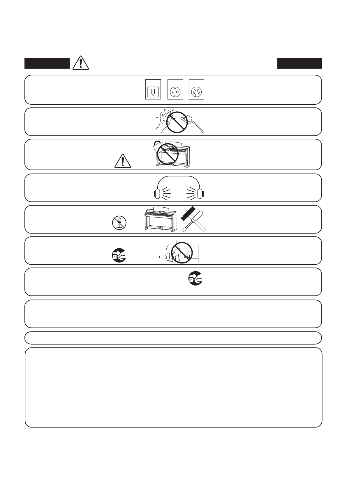
When using electrical products, the following basic precautions should always be followed:
WARNING
The product should be connected to
an AC outlet of the specied voltage.
Do not insert or disconnect the power
cord plug with wet hands.
Take care not to allow any foreign
matter to enter the product.
When using the headphones, do not
listen for long periods of
time at high volume levels.
Do not disassemble, repair or modify
the product.
Indicates a potential hazard that could result in death or
serious injury if the product is handled incorrectly.
120V 240V230V
If you are going to use an AC power cord,
make sure that its has the correct plug shape
and conforms to the specied power voltage.
Failure to do so may result in re.
Doing so may cause electric shock.
Entry of water, needles or hair pins may result
in breakdown or short-circuit.
The product shall not be exposed to dripping or
splashing. No objects lled with liquids, such as
vases, shall be placed on the product.
Doing so may result in hearing problems.
Doing so may result in product breakdown,
electric shock or short-circuit.
When disconnecting the AC power cord's
plug, always hold the plug
and pull it to remove it.
The product is not completely disconnected from the
power supply even when the power switch is turned
o. If the product will not be used for a long time,
unplug the AC power cord from the AC outlet.
Pulling the AC power cord itself may damage
the cord, causing a re, electric shock or
short-circuit.
Failure to do so may cause re in case of
lightning.
Failure to do so may over-heat the product,
resulting in re.
It is good practice to place the instrument near the AC outlet and the power cord plug in a position so that it
can readily be disconnected in an emergency because electricity is always charging while the plug is in the
AC outlet even in a power switch o condition.
Ensure that this product is connected to a socket with a protective earth connection.
GROUNDING INSTRUCTIONS
This product must be grounded. If it should malfunction or breakdown, grounding provides a path of least
resistance for electric current to reduce the risk of electric shock. This product is equipped with a cord having
an equipment-grounding conductor and a grounding plug. The plug must be plugged into an appropriate
outlet that is properly installed and grounded in accordance with all local codes and ordinances.
DANGER - Improper connection of the equipment-grounding conductor can result in a risk of electric shock.
Check with a qualied electrician or serviceman if you are in doubt as to whether the product is properly
grounded. Do not modify the plug provided with the product - if it will not t the outlet, have a proper outlet
installed by a qualied electrician.
Page 6
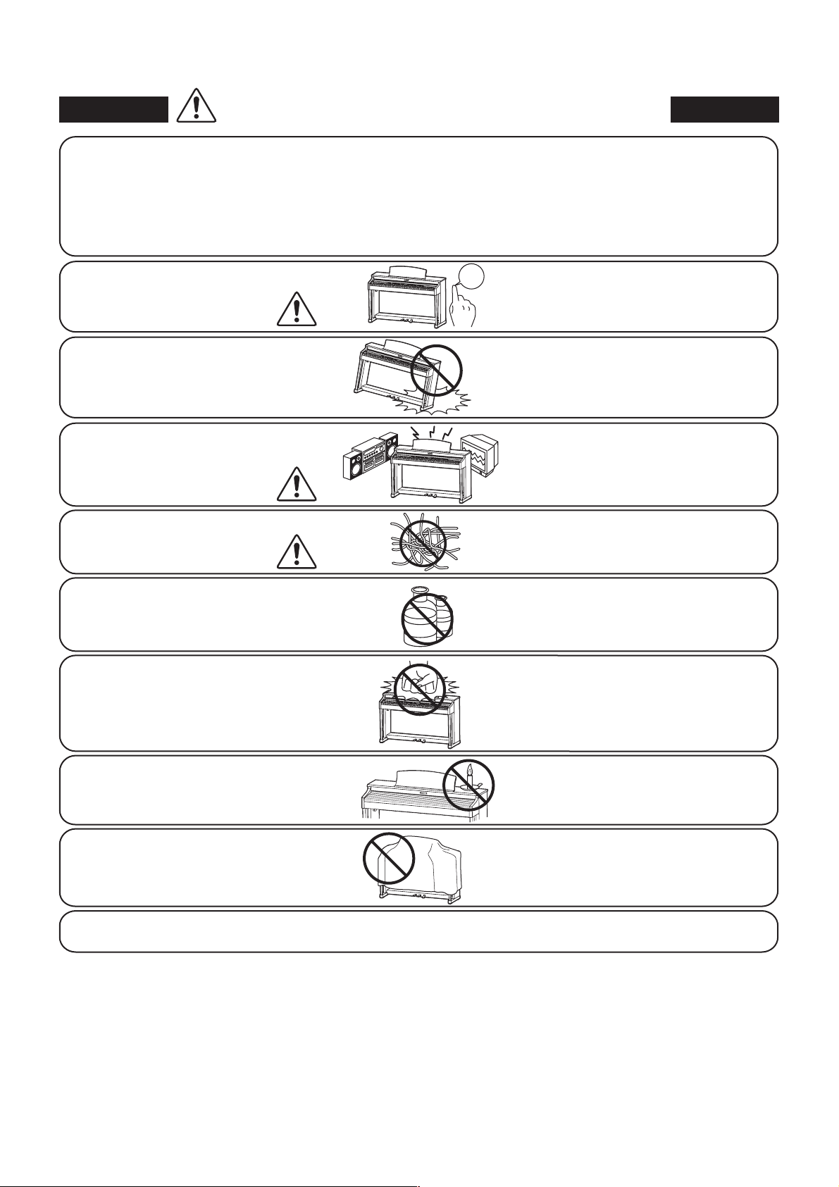
Indicates a potential hazard that could result in injury or
CAUTION
Do not use the product in the following areas.
Areas, such as those near windows, where the product is
exposed to direct sunlight
Extremely hot areas, such as near a heater
Extremely cold areas, such as outside
Extremely humid areas
Areas where a large amount of sand or dust is present
Areas where the product is exposed to excessive
vibrations
damage to the product or other property if the product
is handled incorrectly.
Using the product in such areas may result in
product breakdown.
Use the product only in moderate climates (not
in tropical climates).
Before connecting cords, make sure
that the power to this product
and other devices is turned
OFF.
Do not drag the product on the oor.
Take care not to drop the product.
Do not place the product near electrical
appliances such as TVs and radios.
When connecting the AC power cord
and other cords, take care
not to get them tangled.
Do not wipe the product with benzene
or thinner.
Do not stand on the product or exert
excessive force.
OFF
Failure to do so may cause breakdown of this
product and other devices.
Please lift up the product when moving it.
Please note that the product is heavy and must
be carried by more than two persons.
Dropping the product may result in breakdown.
Doing so may cause the product to generate
noise.
If the product generates noise, move the
product suciently away from the electrical
appliance or connect it to another AC outlet.
Failure to do so may damage them, resulting in
re, electric shock or short-circuit.
Doing so may result in discoloration or
deformation of the product.
When cleaning the product, put a soft cloth in
lukewarm water, squeeze it well, then wipe the
product.
Doing so may cause the product to become
deformed or fall over, resulting in breakdown
or injury.
Do not place naked ame, such as lighted
candles on the product.
Ensure that the ventilation is not
impeded by covering the ventilation
openings with items, such as newspaper,
table-cloths, curtains, etc.
The product should be located so that its location or position does not interfere with its proper ventilation. Ensure a
minimum distance of 5cm around the product for sucient ventilation.
Doing so may cause the illumination to fall over,
resulting in re.
Failure to do so may over-heat the product,
resulting in re.
6
Page 7
7
• The power supply cord or the plug has been damaged.
• Objects have fallen, or liquid has been spilled into the product.
• The product has been exposed to rain.
• The product does not appear to operate normally or exhibits a marked change in performance.
• The product has been dropped, or the enclosure damaged.
&)
Should an abnormality occur in the product, immediately turn the power OFF, disconnect the power cord plug, and then contact
the shop from which the product was purchased.
#-+$
,)&#&!"#*(()+*%+*)"
#%(')&The wires in this mains lead are coloured in accordance with the following code:
• GREEN-AND-YELLOW: EARTH
• BLUE: NEUTRAL
• BROWN: LIVE
As the colours of the wires in the mains lead of this apparatus may not correspond with the coloured markings identifying the
terminals in your plug, proceed as follows.
• The wire which is coloured GREEN-AND-YELLOW must be connected to the terminal in the plug which is marked by the
letter E or by the safety earth symbol or coloured GREEN or GREEN-AND-YELLOW.
• The wire which is coloured BLUE must be connected to the terminal which is marked with the letter N or coloured BLACK.
• The wire which is coloured BROWN must be connected to the terminal which is marked with the letter L or coloured RED.
-.-
If your product is marked with this recycling symbol it means that, at the end of its life, you must dispose of it separately
by taking it to an appropriate collection point. You should not mix it with general household waste. Disposing of this
product correctly will prevent potential negative eects on the environment and human health which could otherwise
arise due to inappropriate waste handling. For further details, please contact your local authority. (European Union only)
#-.+*
+#'& Changes or modications not expressly approved by the party responsible for compliance could void the user’s
authority to operate the equipment.
&' This equipment has been tested and found to comply with the limits for a Class B digital device, pursuant to Part 15 of the
FCC Rules. These limits are designed to provide reasonable protection against harmful interference in a residential installation.
This equipment generates, uses and can radiate radio frequency energy and, if not installed and used in accordance with the
instructions, may cause harmful interference to radio communications. However, there is no guarantee that interference will not
occur in a particular installation. If this equipment does cause harmful interference to radio or television reception, which can be
determined by turning the equipment o and on, the user is encouraged to try to correct the interference by one or more of the
following measures:
• Reorient or relocate the receiving antenna.
• Increase the separation between the equipment and receiver.
• Connect the equipment into an outlet on a circuit dierent from that to which the receiver is connected.
• Consult the dealer or an experienced radio/TV technician for help.
--.
Products:
Model Number:
Responsible Party Name:
Address:
Telephone:
This device complies with Part 15 of the FCC Rules. Operation is subject to the following two conditions:
(1) this device may not cause harmful interference, and
(2) this device must accept any interference received, including interference
that may cause undesired operation.
Electronic Piano
MP7
Kawai America Corporation
2055 East University Drive, Rancho Dominguez, CA 90220
310-631-1771
This applies only to products distributed by Kawai America Corporation.
Page 8

TableofContents
Important Safety Instructions ...................4
Table of Contents ................................8
Introduction
Welcome to the MP7 ...........................10
1. Feature Highlights ..............................10
2. Owner's Manual Conventions .................. 11
Part Names & Functions ........................12
1. Front Panel: Knobs, Faders & Buttons ...........12
2. Front Panel: Jacks & Connectors ................16
3. Rear Panel: Jacks & Connectors ................. 16
Connecting to Other Devices ..................18
Understanding the MP7 ........................19
EDIT Menu
Overview of the EDIT Menu (INT mode) ............38
EDIT Menu Parameters (INT mode) ................40
1. Reverb ..........................................40
2.1. EFX ............................................40
2.2 Amp Simulator (E.PIANO) ........................41
3. Sound ..........................................42
4. Tuning ..........................................44
5. Key Setup .......................................45
6. Controllers ......................................48
7. K n o b A ss i g n ....................................50
8. Virtual Technician (PIANO sounds) ..................52
Virtual Technician (E.PIANO, HARPSI, BASS sounds) ......53
Main Operation
Getting Started .................................20
Selecting Sounds ...............................21
Zone Functions .................................22
1. Zone Basics .....................................22
2. Zone Modes (INT/EXT/BOTH) ........................23
3. Zone Key Range ................................24
LCD Display & Control Knobs ..................26
Eects Section Functions ......................27
1. Reverb ..........................................27
2. EFX .............................................28
3. Amp Simulator (MAIN zone only) ....................30
Virtual Technician (DRAWBAR sounds) ...............53
Overview of the EDIT Menu (EXT mode) ...........54
EDIT Menu Parameters (EXT mode) ................56
1. Channel/Program ...............................56
2. SETUP ...........................................56
3. Transmit ........................................57
4. MMC ............................................57
5. Key Setup .......................................58
6. Controllers ......................................60
7. K n o b A ss i g n ....................................61
Overview of the EDIT Menu (BOTH mode) ..........62
STORE Button & SETUPs
Tonewheel Organ Mode ........................32
Global Section ..................................32
1. EQ. . . . . . . . . . . . . . . . . . . . . . . . . . . . . . . . . . . . . . . . . . . . . . . 34
2. Transpose .......................................36
3. Local O ........................................37
8
Overview of the STORE Button .................63
1. Storing a SOUND ...............................63
2. Storing a SETUP .................................64
3. Storing POWERON settings .....................65
SETUP Memories ...............................66
Page 9

9
Recorder
SYSTEM Menu
Overview of the Recorder ......................67
Song Recorder (Internal memory) ....................68
1. Recording a song ...............................68
2. Playing back a song ............................70
3. Saving a song as an SMF le ....................72
4. Loading an SMF le into memory ..............73
5. Erasing a song ..................................76
6. Song Transpose .................................77
7. Panel Mode .....................................77
8. MIDI to Audio ...................................77
9. SMF Direct Play .................................78
SMF Mixer ......................................79
Audio Record/Playback (USB memory) ..............80
Overview of the SYSTEM Menu ...............10 4
SYSTEM Menu Parameters & Functions .......105
1. Utility ..........................................105
2. Pedal. . . . . . . . . . . . . . . . . . . . . . . . . . . . . . . . . . . . . . . . . . .106
Expression/Damper pedal calibration .........107
3. MIDI ...........................................10 8
4. Oset ..........................................109
5. User Edit .......................................109
Creating a User Touch Curve. . . . . . . . . . . . . . . . . . . 110
Creating a User Temperament .................111
Creating a User Key Volume ...................112
Creating a User Stretch Tuning ................113
6. Reset ...........................................11 4
1. Recording an audio le .........................80
2. Playing an audio le ............................83
3. Overdubbing an audio le ......................86
4. MIDI to Audio ...................................89
Metronome .....................................92
1. Click mode ......................................92
2. Rhythm mode ..................................93
3. Recording with the metronome ................96
USB Menu
Overview of the USB Menu .....................98
USB Menu Functions ...........................99
1. Load ............................................99
Panel Lock ( ) .................................115
Appendix
USB MIDI (USB to Host Connector) ....................116
Software Update ..............................117
Sound List .....................................118
Rhythm Pattern List ...........................119
EFX Categories, Types, & Parameters .........120
Specications ..................................12 5
MIDI Implementation .........................126
1. Recognised Data ...............................127
2. Transmitted Data ..............................131
3. Exclusive Data .................................132
2. Save ...........................................100
3. Delete .........................................101
4. Rename ........................................102
5. Format .........................................103
4. SOUND/SETUP Program/Bank .................139
5. Program Change Number List .................140
6. Control Change Number (CC#) Table ..........142
MIDI Implementation Chart ......................144
Page 10

Welcome to the MP7
1
Feature Highlights
‘Responsive Hammer 2’ weighted-key action, with Ivory Touch key surfaces and Let-o simulation
The MP7’s Responsive Hammer 2 (RH2) keyboard action recreates the distinctive touch of an acoustic grand piano, with its realistic
movement and accurate 3-sensor technology providing a smooth, natural, and highly responsive piano playing experience. The
weight of the keyboard is appropriately graded to mirror the heavier bass hammer s and lighter treble hammers of an acou stic piano,
while structural reinforcements within the action assembly ensure greater stability during fortissimo and staccato passages.
The RH2 keyboard action also reproduces the subtle let-o sensation felt when playing the keys of a grand piano very softly,
Introduction
enhancing delicate pianissimo playing to satisfy the expectations of even the most discerning pianists. Finally, the MP7 keyboard
action features Kawai’s Ivory Touch key surfaces as standard. This nely textured material gently absorbs moisture to assist playing
control, and possesses a natural, matte nish that is smooth, but not slippery.
The ultimate pianos for Concert, Pop, and Jazz
The MP7 captures the beautiful sound of Kawai’s highly acclaimed hand-built concert grand piano, with all 88 keys of this
exceptional instrument meticulously recorded, analysed and faithfully reproduced using proprietary Harmonic Imaging™ XL
technology. This unique process accurately recreates the broad dynamic range of the original grand piano, aording pianists an
extraordinary level of expressiveness ranging from the softest pianissimo to the strongest, boldest fortissimo.
With separate variations for Concert, Pop, and Jazz playing, the MP7 oers an excellent selection of high quality acoustic piano
sounds suitable for various musical styles, including a separate sub-category devoted entirely to upright and mono pianos.
Moreover, Kawai’s unique Virtual Technician feature allows various characteristics of the selected acoustic piano sound to be
shaped at the touch of a button or the turn of a knob, with parameters to adjust voicing and regulation, string and damper
resonances, and subtle hammer, damper, and key release noises.
VintageEPs,twineects,andampsimulation
The MP7 also features an excellent selection of vintage electric piano sounds, each with their own distinctive charac teristics. Enjoy
their natural, organic sound, or pass the signal through a wide variety of classic eects stomp boxes, before plugging into one of
the ve classic amp and speaker cabinets – complete with realistic microphone character and position modelling.
Classic tonewheel organs with drawbar control and authentic percussion
The MP7’s brand new tonewheel organ simulation transforms the stage piano into a vintage electromechanical organ, complete
with nine real-time adjustable drawbars and authentic percussion controls. Organ enthusiasts can dial-in favourite drawbar
registrations, adjust the ‘condition’ of the organ tone, and select their preferred rotary speaker character, then store the sound to
memory for immediate recall. With organ mode selected, the MP7 adjusts the strike point for the keyboard, allowing blazing runs
and greasy licks to be played on its fully-weighted action as easily as the real thing.
High quality strings, pads, brasses, basses and more
Supplementing the realistic acoustic pianos, vintage electric pianos, and growling tonewheel organs, the MP7 features a broad
range of high quality strings, pads, synths, brass and woodwind voices, basses, guitars, and a whole host of other useful sounds.
These supplementary sounds are ideal for building layers, adding texture to other instruments, or for playing individually, at
the front of the mix. And if the stock sound isn’t quite perfect, feel free to customise and tweak using the MP7’s exible ADSR
parameters and resonance/cut-o controls – all immediately accessible directly from the panel.
Four zone master keyboard controller
The MP7 maintains the MP series’ classic four-zone approach, with each zone able to play internal sounds, external MIDI devices,
or both types simultaneously. Zones can be played individually, or freely split, layered and velocity switched to create stunning
personalised performances. The MP7’s powerful customisation allows parameters and settings for each zone to be adjusted and
controlled independently, making for an unbelievably versatile all-in-one performance instrument.
10
Intuitive operation, large LCD, real-time assignable control knobs
The MP7’s control panel is clearly arranged and easy to use, with related functions grouped together and placed where you’d
expect to nd them. A large LCD display and four assignable control knobs, allow several parameters to be adjusted directly in
real-time, without getting lost in menus – concentrate on playing, rather than trying to remember which button does what.
Page 11
256Setupmemories:enoughforthe busiest stage musician
The MP7 allows every single customised sound, knob position, fader level, and adjustable parameter to be stored in memory as a
SETUP, and recalled at the touch of a button. With over 250 SETUP memories, the MP7 is ideal for busy stage musicians who like
to plan several shows ahead, before going out on the road.
USB to Device functionality, with MP3/WAV/SMF le recording and playback
The MP7 is equipped with USB connectors that not only allow the instrument to be connected to a computer for MIDI use, but also
to load and save data to USB memory devices directly. This ‘USB to Device’ feature allows customised sounds, SETUP memories,
and recorder songs stored in internal memory to be saved to USB for posterity.
USB memory devices can also be used to play back MP3 or WAV audio or SMF MIDI les, allowing performing musicians to
play along with professional backing tracks, or simply learn the chords or melody for a new piece. It is even possible to save
performances directly as MP3, WAV, or SMF les for emailing to band members, casual listening away from the keyboard, or fur ther
editing using an audio workstation.
2
Owner’s Manual Conventions
This owner’s manual utilises a number of illustrative conventions in order to explain the MP7’s various functions.
The examples below provide an overview of the button LED indicator states and press types, and the appearance of
dierence kinds of explanation text.
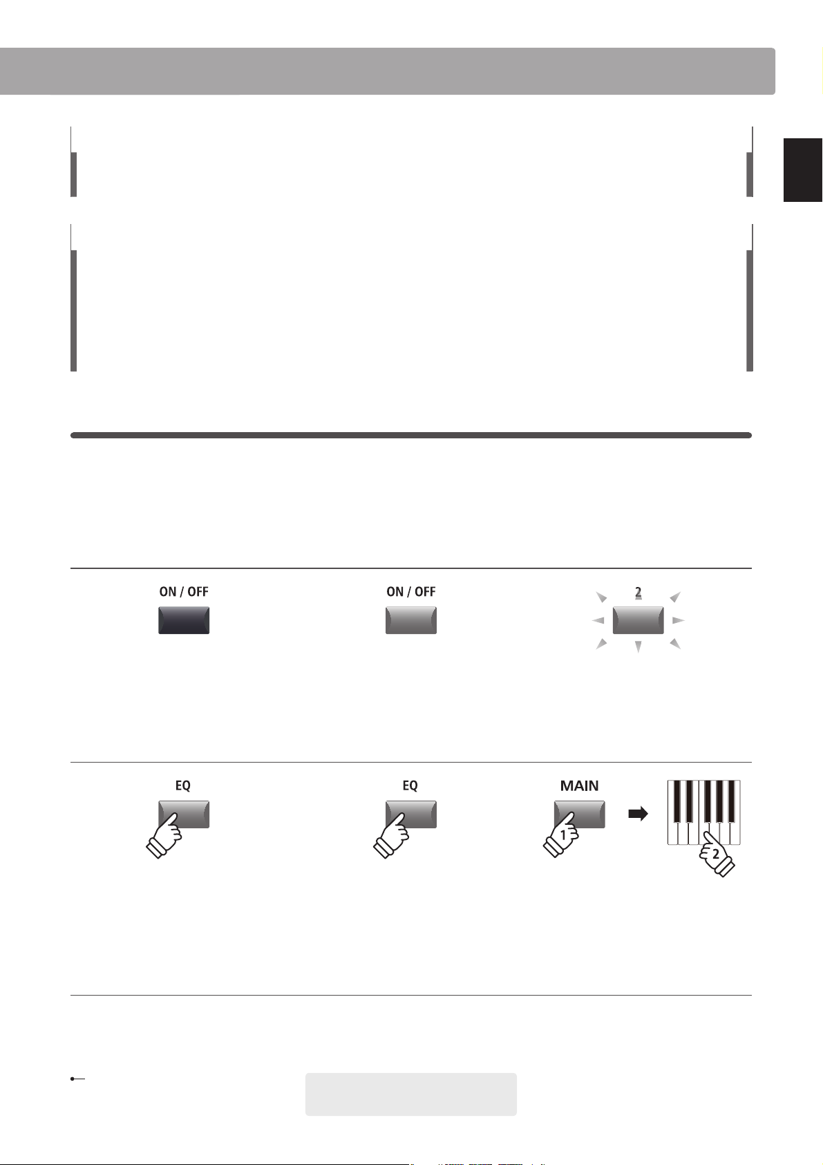
Button LED indicator states
LED indicator OFF:
Sound/Function is not selected.
LED indicator ON:
Sound/Function is selected.
LED indicator ashing:
Sound/Function is selected in a
temporary state.
Introduction
Button press types
Normal press:
Select a sound or function, or
turn a function ON/OFF.
Text appearance
Normal instruction and explanation text
is written in regular type at 9 pt. size.
Captions explaining the LCD display
or button functions, are written in
bold type at 8.5 pt. size.
hold
Press and hold:
Show a function’s parameters.
* Notes about functions are marked with an
asterisk and written in 7.5 pt. size.
Example operations are written in italic type
at 8 pt. size, and enclosed within a grey box.
hold
Press and hold, then press X:
Set split points, create zone
ranges, set transpose key, etc.
Reminders, hints, and additional explanations are written in italic type at 9 pt. size.
11
Page 12
Part Names & Functions
Introduction
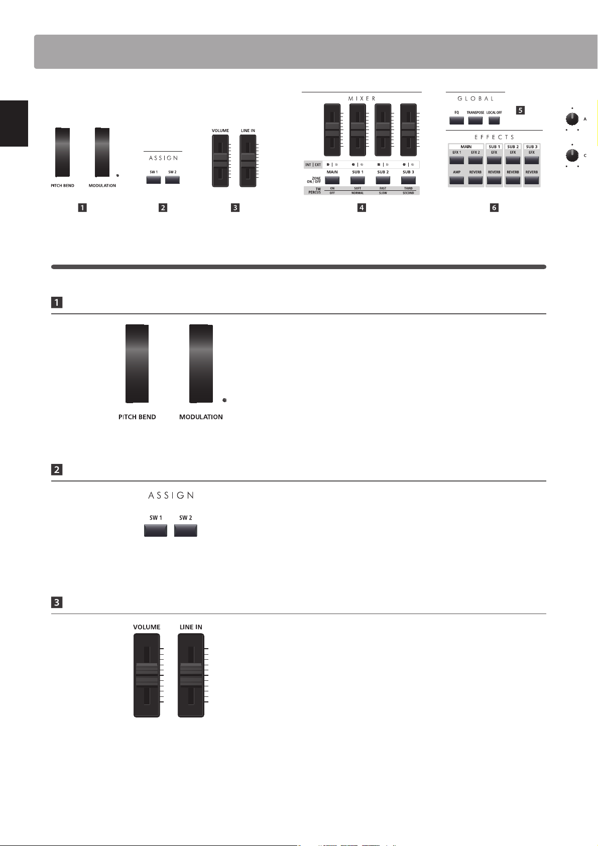
1
Front Panel: Knobs, Faders & Buttons
Control Wheels
PITCHBENDwheel
This control wheel smoothly bends the pitch up or down from
its current value.
ASSIGN Buttons
Volume Faders
MODULATION wheel
This control wheel controls the modulation (vibrato) depth.
Moving the wheel forward increases the vibrato depth.
The LED indicator will turn ON when this wheel is in use.
* Alternative functions can be assigned to the MODULATION wheel in the
Controllers page of the EDIT menu (page 48).
SW1 / SW2 buttons
These buttons turn user-assigned functions ON or OFF.
Various dierent functions can be assigned to these buttons,
allowing immediate control during performances.
* Press and hold either button to show the respective assign parameters of
the EDIT menu in the LCD display.
* For more information about assigning functions, please refer to page 48.
MASTERVOLUMEfader
This fader controls the volume level of the MP7’s OUTPUT and
HEADPHONE jacks.
12
LINE IN fader
This fader controls the LINE IN volume level.
* The LINE IN volume level can be further adjusted by using the Input Level
parameter in the Utility page of the SYSTEM menu. For more information,
please refer to page 105.
Page 13
13
Introduction
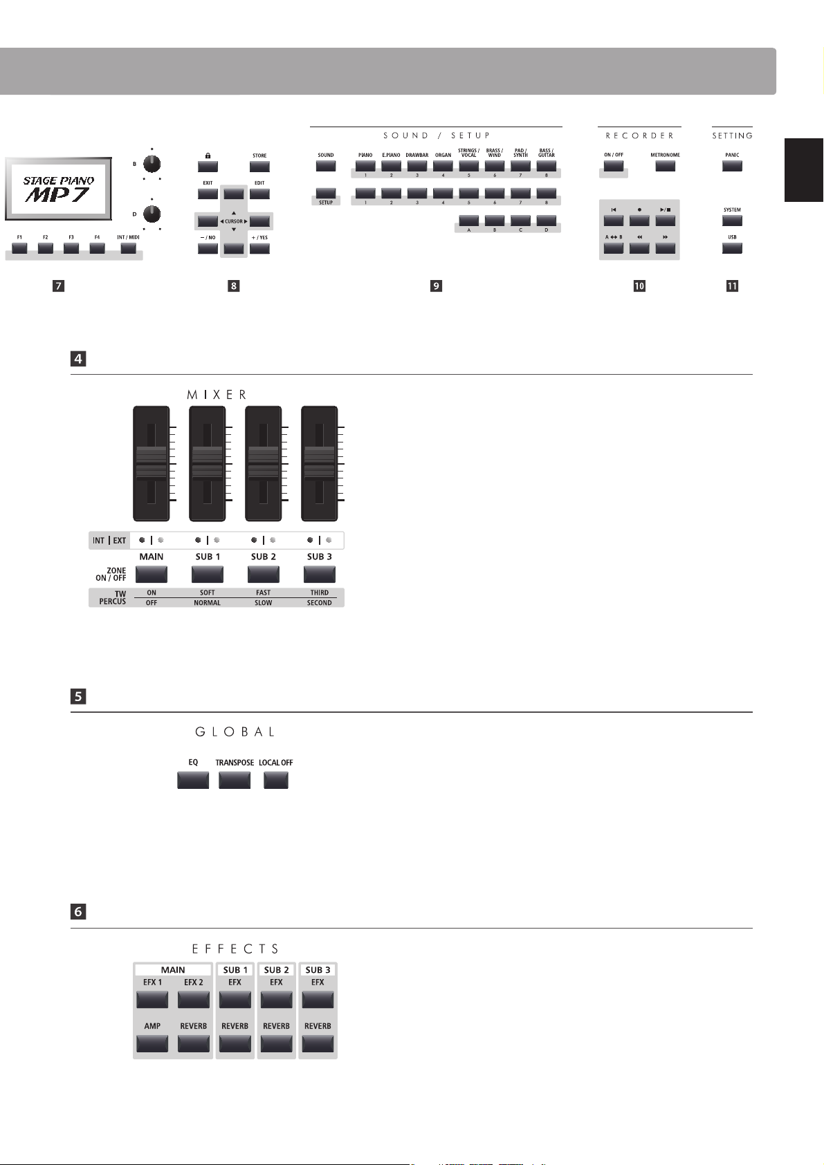
MIXER Section
GLOBAL Section
VOLUME faders
These faders control the individual volume levels of the MAIN,
SUB1, SUB2, and SUB3 zones. When multiple zones are active,
these faders can be used as an audio mixer.
When the tonewheel organ mode is selected, these faders are
used to adjust the position of the assigned drawbars.
INT/EXT LEDs
These LEDs indicate whether a zone is controlling an internal
sound, an external MIDI device, or both simultaneously.
ZONE ON/OFF buttons
These buttons turn the MAIN, SUB1, SUB2, and SUB3 zones ON
or OFF.
When the tonewheel organ mode is selected, these buttons are
used to change the percussion characteristics of the organ.
LOCAL OFF
This button disables the internal connection between the MP7’s
keyboard and tone generators.
EFFECTS Section
* Press and hold each button to show the respective settings pages of the
EDIT menu in the LCD display.
EQ button
This button turns the global EQ ON or OFF.
* Press and hold this button to show the EQ settings in the LCD display.
TRANSPOSE button
This button turns the TRANSPOSE function ON or OFF.
* Press and hold this button to show the transpose settings pop-up in the
LCD display.
EFX1/EFX2/EFX buttons
These buttons turn the eects for each zone ON or OFF. The
MAIN zone has two eect modules, while the SUB1, SUB2, and
SUB3 zones have one eect module each.
AMP button
This button turns the amp simulator for the MAIN zone ON or
OFF.
REVERB buttons
These buttons turn the reverb for each zone ON or OFF.
Page 14
Part Names & Functions
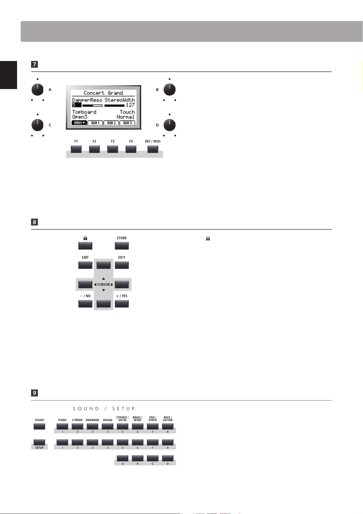
DISPLAY Section
Introduction
LCD Display
The LCD display provides a visual indication of the selected
zone and sound, parameter values, and the status of other
functions when active
.
A/B/C/D control knobs
These knobs adjust displayed parameter values in real-time.
* EDIT menu parameters can be freely assigned to each of the four knobs in
the Knob Assign page of the EDIT menu (page 50).
F1/F2/F3/F4 buttons
These buttons select the four zones (MAIN, SUB1, SUB2, SUB3)
to be displayed and controlled. In other modes (e.g. Recorder)
these buttons also select additional functions.
INT / MIDI button
This button is used in conjunction with the +/YES or –/NO
buttons to change the zone mode (INT, EXT, or BOTH).
EDIT Section
–/NO +/YESbuttons
These buttons decrease or increase the value of the selected
parameter, and also cancel or conrm operations that require
user interaction (e.g. Erasing data).
SOUND / SETUP Section
LOCK ( )button
This button locks the MP7’s control panel, thus preventing any
accidental button pushes during a performance.
STORE button
This button stores edited SOUNDS, or full panel settings to the
SETUP and POWERON memories.
EXIT button
This button exits the current mode or page.
EDIT button
This button enters the EDIT menu. When the EDIT menu is
displayed, this button also enters the selected parameter
category page.
CURSOR buttons
These buttons move the selection cursor and scroll through the
various pages of the EDIT menu.
14
SOUND button
This button sets the MP7 to SOUND mode, whereby the buttons
on the right will select the instrument’s 256 internal sounds.
SETUP button
This button sets the MP7 to SETUP mode, whereby the buttons
on the right will select the instrument’s 256 SETUP memories.
SOUND/SETUP SELECTION buttons
In SOUND mode, these buttons select the category, type, and
variation of the zone’s sound. In SETUP mode, these buttons
select the bank and memory used for the SETUP.
Page 15
15
Introduction
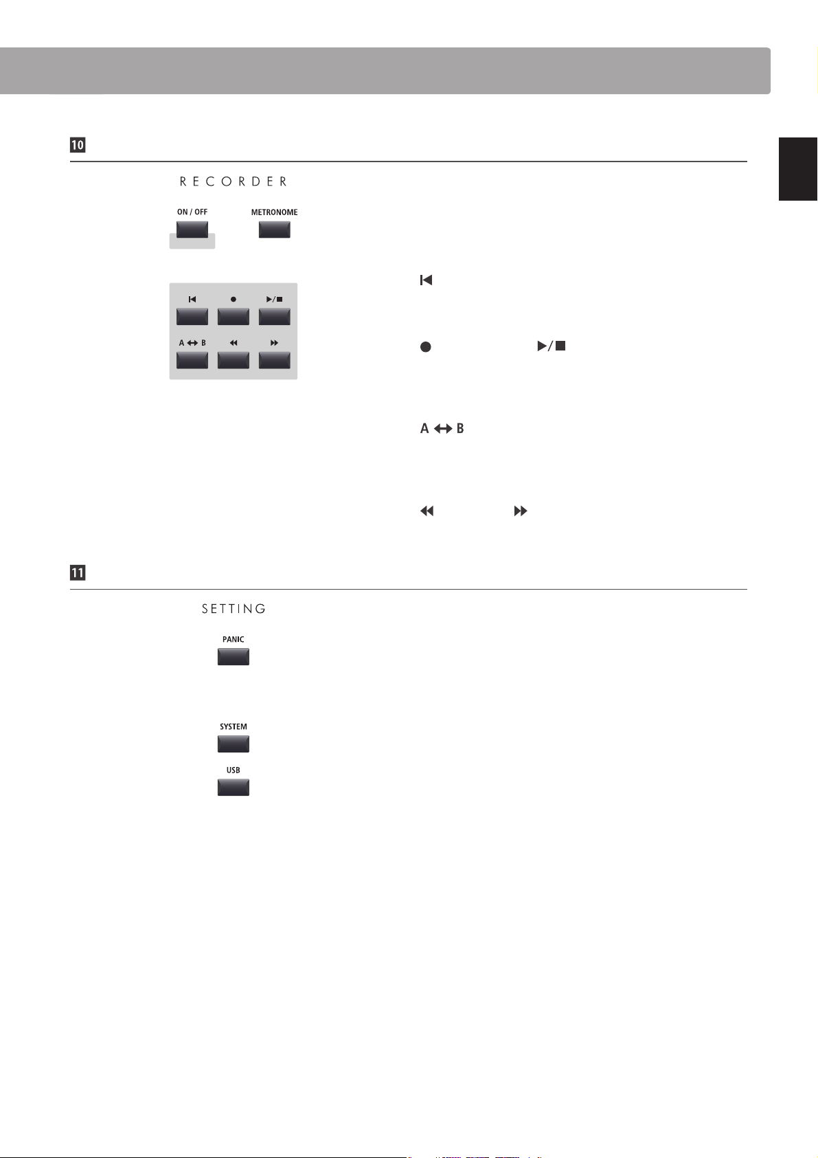
RECORDER Section
ON/OFF button
This button turns the RECORDER section ON or OFF.
METRONOME button
This button activates the METRONOME or RHYTHM patterns.
(RESET) button
This button resets the MP7’s song recorder, rewinding songs
and MP3/WAV/SMF les to the beginning.
(RECORD) and (PLAY/STOP) buttons
These buttons record and playback/stop songs stored in
the MP7’s internal memory, or MP3/WAV les saved to a USB
memory device.
(LOOP) button
This button activates the MP7’s A-B Loop function, allowing
passages of a recorder song or MP3/WAV/SMF le to be played
back repeatedly.
(REW) and (FWD) buttons
These buttons are used to move the playing position of the
current recorder song or MP3/WAV/SMF backward or forward.
SETTING Section
PAN IC butt on
This button returns the MP7 to the Power On state, and also
sends All Note O and Reset All Controller messages via MIDI.
SYSTEM button
This button enters the SYSTEM menu, allowing many aspects of
the MP7’s functionality to be adjusted.
USB button
This button enters the USB menu, allowing data to be loaded
and saved from/to a connected USB memory device.
Page 16
Part Names & Functions
2
Front Panel: Jacks & Connectors
Introduction
3
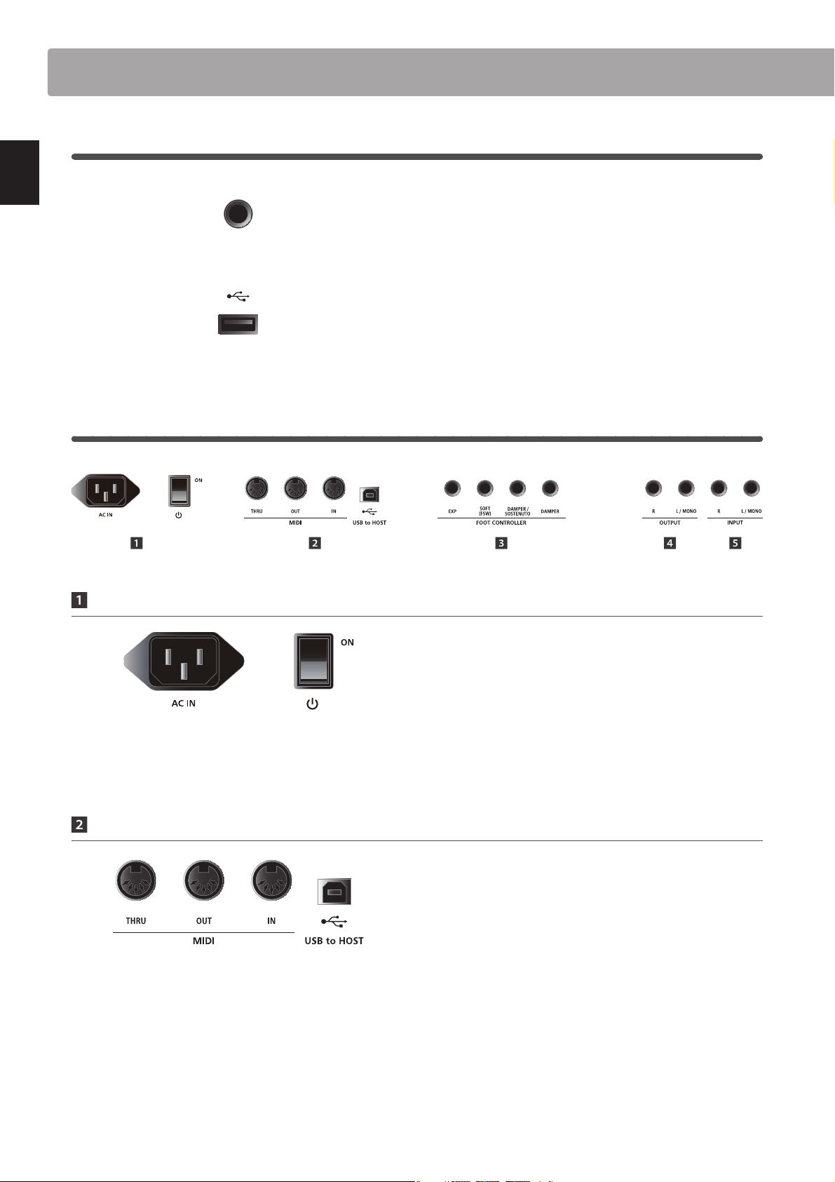
Rear Panel: Jacks & Connectors
HEADPHONE jack
The headphone jack is located at the left end of the key slip and
used to connect a pair of headphones equipped with a standard
1/4” phone jack.
USBTODEVICEport
The USB to Device port is located at the right end of the key
block and used to connect a FAT or FAT32 formatted USB
memory device to load and save data.
POWER Section
MIDI Section
.
* The instrument’s USB MIDI port and MIDI IN/OUT jacks can be connected
and used simultaneously. To adjust MIDI routing, please refer to the MIDI
parameters in the SYSTEM menu, explained on page 108.
AC IN
Connect the power cable included with the MP7 to this
receptacle.
POWER SWITCH
This switch turns the MP7 ON and OFF.
* The MP7 features a power saving mode that can turn o the instrument
automatically after a specied period of inactivity. For more information,
please refer to page 105.
MIDI THRU/OUT/IN jacks
These jacks are used to connect the MP7 to external MIDI
devices, and also to a computer with a MIDI interface as an
alternative to the ‘USB to Host’ port.
USBTOHOSTport
This port is used to connect the MP7 to a computer using a
USB cable. When connected, the instrument can be used as a
standard MIDI device, allowing it to send a receive MIDI data.
Connect a ‘B’ type USB connector to the instrument, and an ‘A’
type USB connector to the computer.
* When connecting the MP7 to a computer using the ‘USB to Host’ port,
additional driver software may be required. For more information, please
refer to page 116.
16
Page 17
17
Introduction
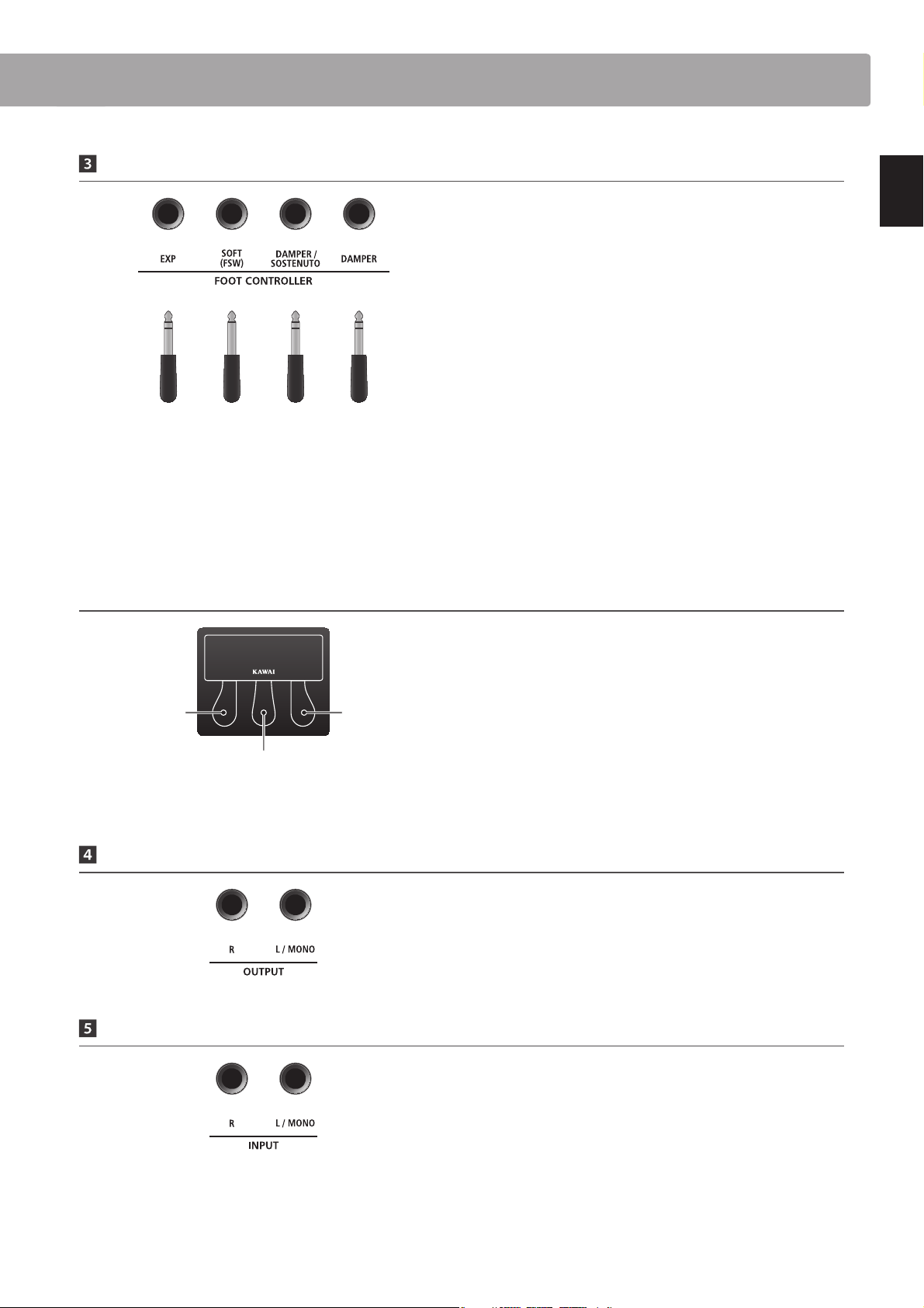
FOOT CONTROLLER Section
EXP jack
This jack is used to connect an expression pedal.
* For information about calibrating the expression pedal to ensure correct
operation with the MP7, please refer to page 107.
SOFT (FSW) jack
This jack is used to connect a momentary foot switch pedal to
the MP7. When using the Kawai F-30 triple pedal accessory, this
jack can also be used to connect the soft pedal to the MP7.
Expression
* Functions can be freely assigned to each foot controller in the Controllers
page of the EDIT menu. For more information, please refer to page 48.
* For more information about purchasing the F-30 triple pedal accessory,
please contact your local Kawai distributor.
Kawai F-30 triple pedal accessory: default pedal assignments
Left pedal:
Soft
F-30 / Footswitch
Centre pedal:
Sostenuto
F-30
F-10H
DAMPER/SOSTENUTO jack
When using the Kawai F-30 triple pedal accessory, this jack is
used to connect the damper and sostenuto pedals to the MP7.
DAMPER jack
This jack is used to connect the included F-10H damper pedal
to the MP7.
By default, with the optional F-30 triple pedal unit connected,
the right pedal acts as a damper pedal, the centre pedal acts as
a sostenuto pedal, and the left pedal functions as a soft pedal.
Right pedal:
Damper
* Functions can be freely assigned to each foot controller in the Controllers
page of the EDIT menu. For more information, please refer to page 48.
OUTPUT Section
INPUT Section
OUTPUT jacks
These jacks are used to connect the MP7 to a musical instrument
amplier, PA system, or recording console using standard 1/4”
phone jacks. To output a mono signal, connect the cable to the
L/MONO jack.
INPUT jacks
These jacks are used to connect a pair of stereo outputs from
other electronic instruments or audio equipment to the MP7.
The input level can be easily adjusted using the LINE IN fader.
When connecting a mono audio source, connect the cable to
the L/MONO jack only.
* When using the Audio Recorder function, the INPUT audio will also be
recorded to the WAV/MP3 le. For more information, please refer to page
80.
Page 18
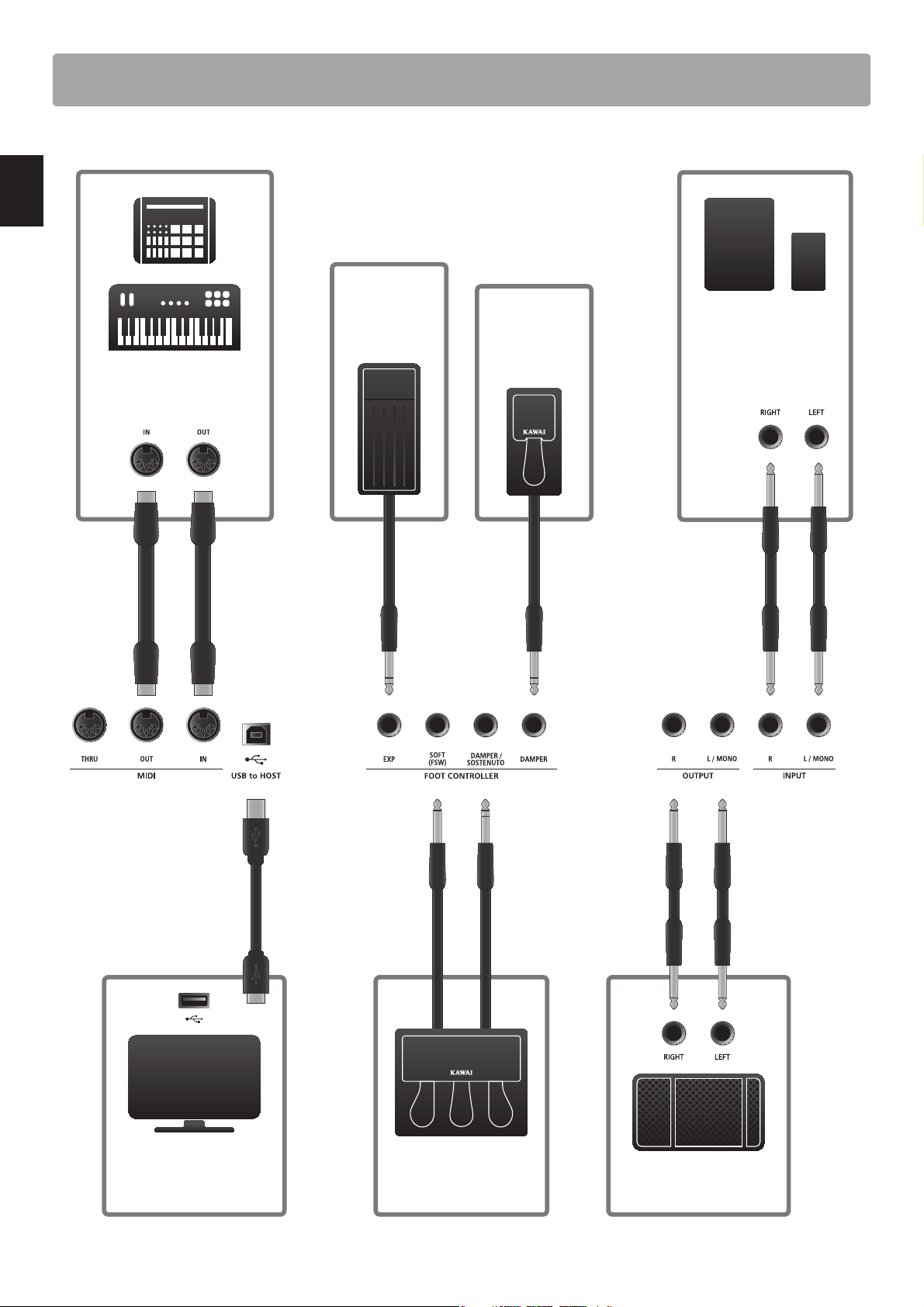
ConnectingtoOtherDevices
Connect an
expression
pedal.
Introduction
Control external MIDI devices,
or connect to a computer with
a MIDI interface.
Connect the
included F-10H
damper pedal.
Connect the stereo output
from tablets, portable
audio devices or other
electronic instruments.
18
USB type ‘A’
USB type ‘B’
Connect to a computer
to exchange MIDI data
and use DAW software.
Connect the F-30 triple
pedal unit accessory.
Connect to ampliers,
speakers, etc.
Page 19
19
Introduction
Understanding the MP7
Preparation before use
The MP7 does not feature built-in speakers. Therefore, in order to listen to the MP7, it will rst be necessary to connect a mixer,
keyboard amplier, or headphones to the instrument.
Once connected to an audio output device, press the POWER SWITCH located on the right of the rear panel to turn on the MP7.
It is recommended to turn on the MP7 before the audio output device in order to avoid the unpleasant switching noise that can
sometimes occur.
MP7 zone struc ture: e xplanation
The MP7 features 4 zones: MAIN, SUB1, SUB2, and SUB3. Each zone features a dedicated VOLUME fader and can be turned ON or OFF
freely. Zones can be set to INT (play the MP7’s internal sounds), EXT (control external MIDI devices) or INT and EXT simultaneously.
When a zone is set to INT, the process of selecting and assigning sounds is largely identical for each zone. However, there are some
important dierences between the MAIN zone and three SUB zones. First, the MAIN zone features two separate EFX modules and
an additional AMP simulator, while the SUB zones each feature one EFX module only. Moreover, the MAIN zone allows any of the 129
eects to be assigned to both EFX modules, however the variety of eects available to the SUB zones’ EFX modules is limited to 22
eects. Finally, the MP7’s tonewheel organ mode can only be used with the MAIN zone is selected, thus the SUB zones are limited
to using the standard PCM organ sounds. All sounds are adjusted using the various parameters in the EDIT menu, with additional
‘Feature Parameters’ that are specic to certain sounds.
REVERB settings are common for all zones, however the depth parameter can be controlled independently for each zone. The
MP7’s EQ is also common for all zones, however parameters in the EDIT menu allow the tonal character for each zone’s sound to be
adjusted independently.
When set to EXT, zones are used to control external MIDI devices. The MAIN and SUB zones share the same MIDI capabilities, allowing
up to four MIDI channels to be independently controlled at the same time. As with INT mode, various parameters to dene transmit/
receive channels, MMC features, keyboard ranges, and knob assignments can be accessed for each EXT zone via the EDIT menu.
Modications to each sound can be stored as individual SOUND presets, while the entire conguration of the MP7 itself can be
stored in one of the 256 SETUP memories.
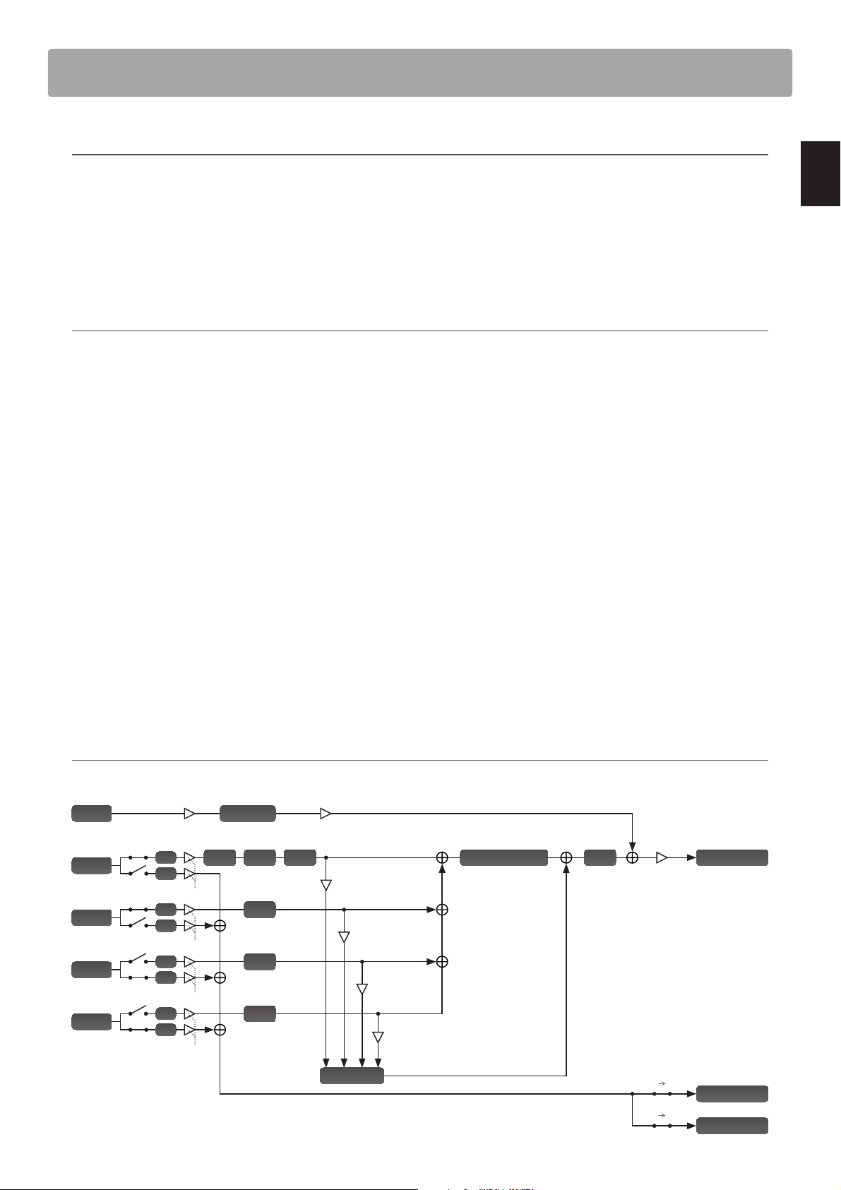
MP7 zone structure: block diagram
The diagram below illustrates the zone structure of the MP7.
Line In
MAIN
SUB1
SUB2
SUB3
Line In Fader Input Level
Zone Mode
INT
EXT
MAIN Fader
INT
EXT
SUB1 Fader
INT
EXT
SUB2 Fader
INT
EXT
SUB3 Fader
Noise Gate
EFX1Amp EFX2
EFX
EFX
EFX
MAIN Reverb Depth
SUB1 Rever b Depth
SUB2 Reverb D epth
SUB3 Rever b Depth
Virtual Technician
EQ
Master Fader
Normal Out
Reverb
Key MIDI
MIDI Out
Key USB
USB-MIDI Out
Page 20
Getting Started
After connecting the power cable, speakers/headphones, and pedals, it’s time to start playing the MP7 stage piano.
This page will explain how to turn on the instrument, set the MAIN zone volume, and adjust the master volume.
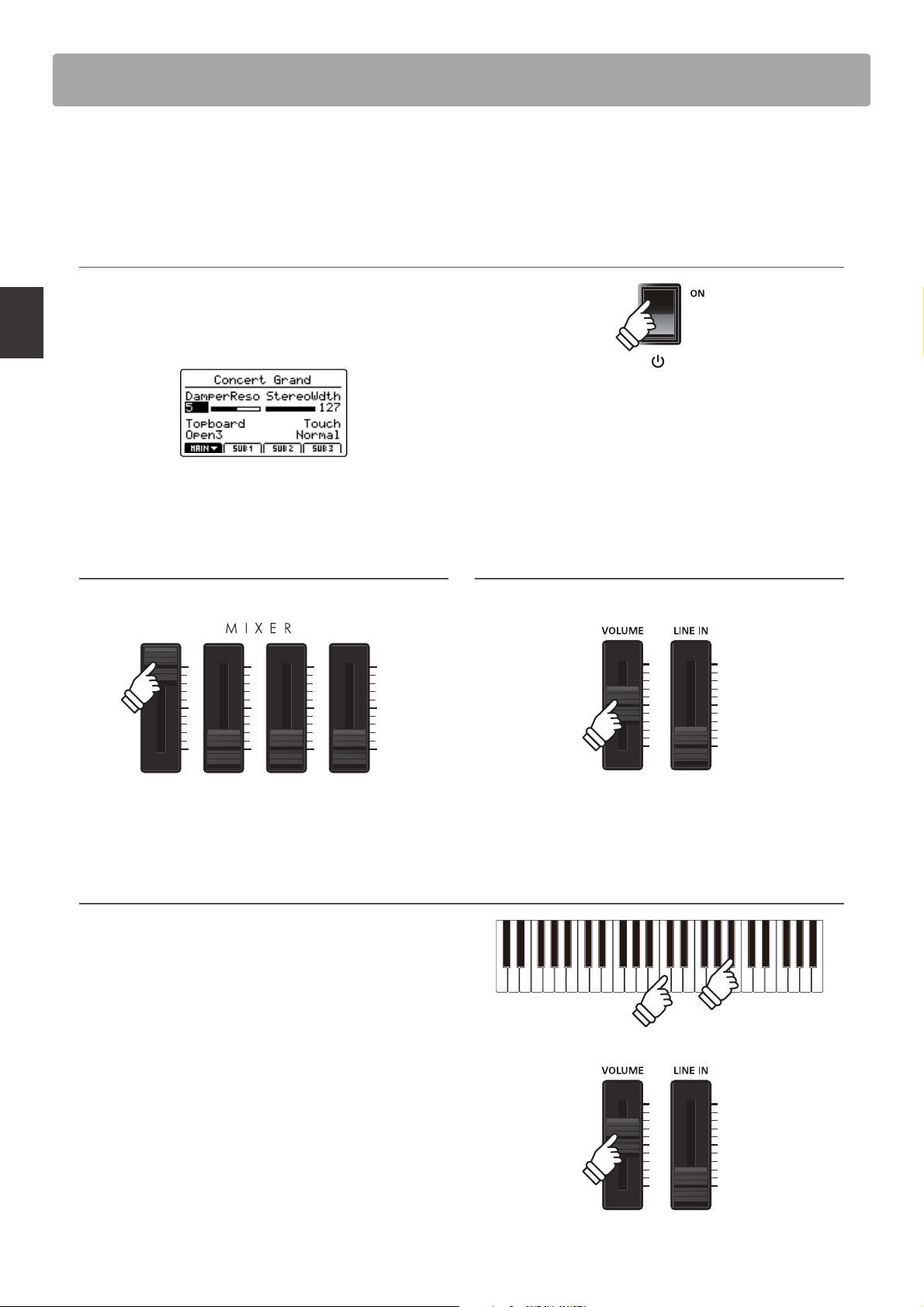
1.TurningtheMP7ON
Press the POWER SWITCH.
The instrument will turn ON, and after a brief period the main
Play Mode screen will be shown in the LCD display.
* For more information about the play screen, please refer to page 26.
Main Operation
* The MP7 features a power saving mode that can turn o the instrument
automatically after a specied period of inactivity. For more information,
please refer to page 105.
2. Adjusting the MAIN zone volume
Move the MAIN zone volume fader to the top-most position.
* For more information about adjusting the volume of zones, please refer
to page 22.
4. Playing the piano
Start playing the piano.
The rich sound of a Kawai EX Concert Grand Piano will be heard
as the keys are pressed.
3. Adjusting the MP7’s master volume
Move the MASTER VOLUME fader to the half-way position.
If necessary, increase or decrease the MASTER VOLUME fader to
nd a comfortable listening level.
20
Page 21
21
Main Operation
Selecting Sounds
The MP7 stage piano features a wide selection of realistic instrument sounds suitable for various musical styles
Sounds are arranged into eight categories, with eight further sub-categories, and four variations, providing a total
of 256 dierent instrument sounds. For a complete listing of the available instrument sounds, please refer to page
118 of this owner’s manual.
* The example below will explain how to select the ‘60’s EP 2’ electric piano sound, however the process is identical for all other sounds.
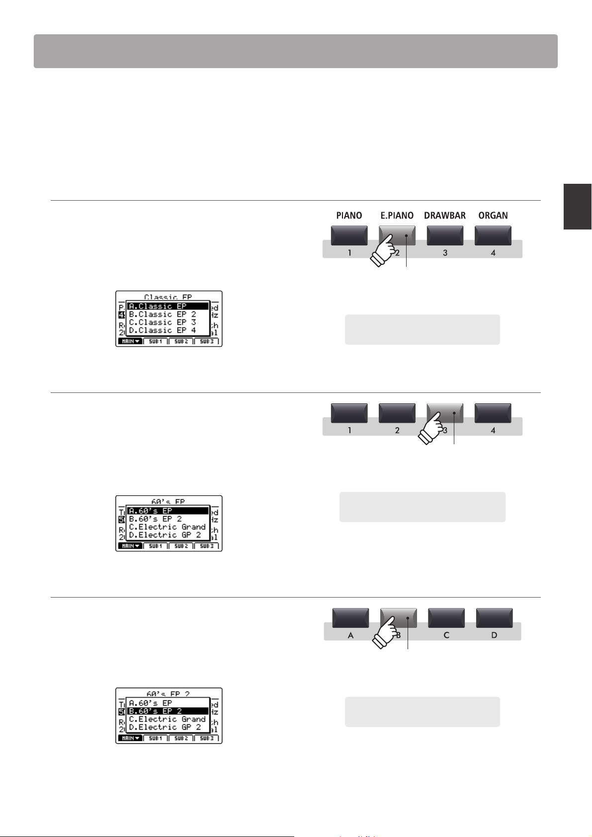
1. Selecting the sound category
Press the desired sound category button from the top row of
sound buttons.
The LED indicator for the button will turn ON to indicate that
the category is selected, and a sound variation pop-up list will
briey be shown in the LCD display.
LED indicator ON:
Category is selected
2. Selecting the sound sub-category
Press the desired sound sub-category button from the middle
row of sound buttons.
The LED indicator for the but ton will turn ON to indicate that the
sub-category is selected, and a sound variation pop-up list will
briey be shown in the LCD display.
3. Selecting the sound variation
Press the desired sound variation button from the bottom row
of sound buttons.
Example: To select the Electric Piano sound
category, press the E.PIANO button.
LED indicator ON:
Sub-category is selected
Example: To select the third sub-category of
electric pianos, press the '3' sub-category button.
The LED indicator for the button will turn ON to indicate that
the variation is selected, and a sound variation pop-up list will
briey be shown in the LCD display.
* Sounds can be selected by pressing the category, sub-category, and
variation buttons in any order.
* When selecting a dierent sound category, the previously selected sub-
category and variation will be recalled automatically.
LED indicator ON:
Sound variation is selected
Example: To select the '60's EP 2' sound, press
the 'B' sound variation button.
Page 22
Zone Functions
1
Zone Basics
As noted in the Introduction chapter, the MP7 features four zones: MAIN, SUB1, SUB2, and SUB3. This page will
explain the process for turning zones ON and OFF, adjusting zone volumes, and creating a simple two zone layer.
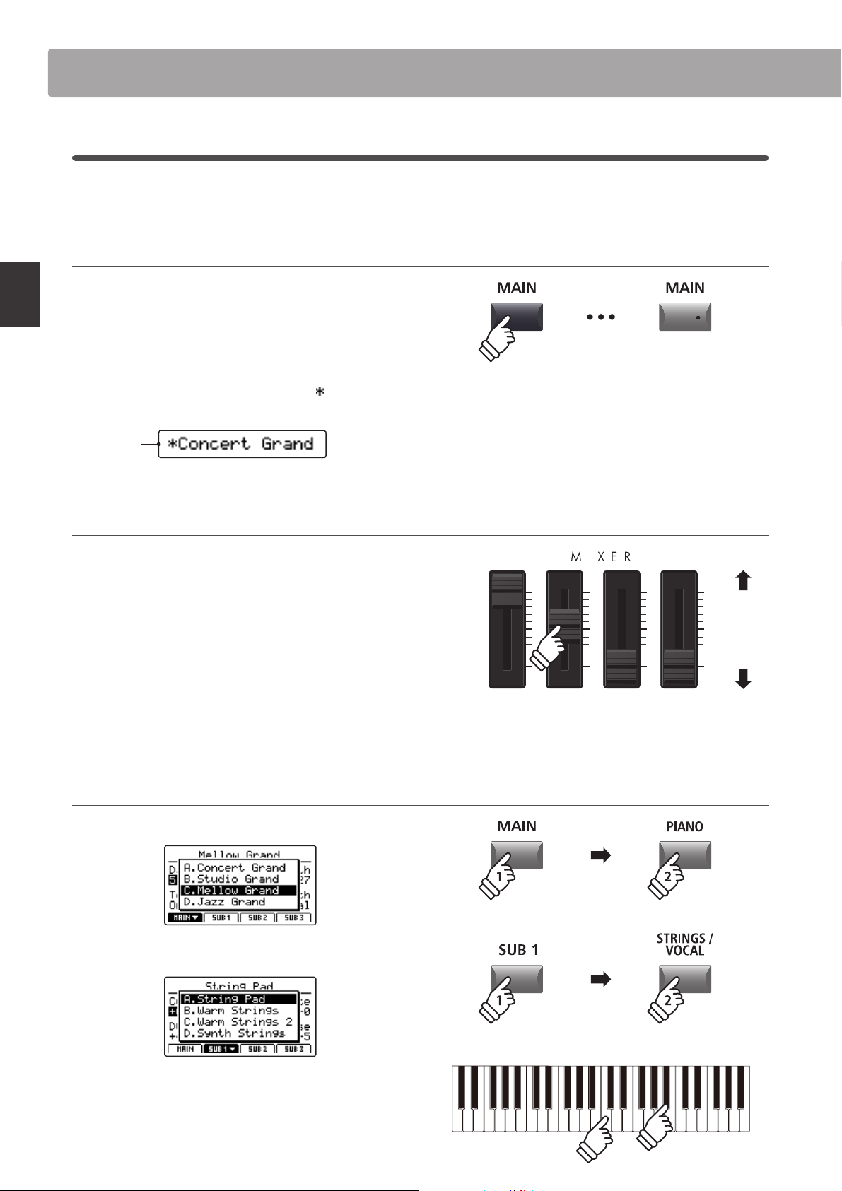
TurningazoneONorOFF
Press the button corresponding to the desired zone to turn that
zone ON or OFF.
The LED indicator for the pressed zone button will turn ON or
OFF to indicate the current status of the zone.
If a zone is turned OFF but then selected, a
added to the left of the sound name in the LCD display.
symbol will be
LED indicator ON:
Zone is turned ON
Main Operation
Zone is
turned OFF
Adjusting the zone volume
Use the VOLUME fader above each zone button to adjust the
volume of that zone.
The volume of the zone will increase or decrease independently
of the other zones.
* When playing with just a single zone (e.g. MAIN), it is recommended to set
the volume fader to the maximum position and use the MASTER volume
fader to adjust the overal volume of the instrument.
To adjust the volume of all sound sections simultaneously, use
the MASTER VOLUME fader (page 12).
Creatingasimpletwozonelayer
First, turn the MAIN zone ON, then select a piano sound.
* When a zone is turned OFF, information for the previously selected (or
neighbouring) zone will be shown in the LCD display.
Increase
volume
Decrease
volume
* When tonewheel organ mode is selected and the soun d edit screen shown
in the LCD display, these VOLUME faders are used to adjust the drawbar
positions of the organ. For more information please refer to page 32.
Next, turn the SUB1 zone ON, and select a strings sound.
Play the layered piano and strings sound, adjusting the MAIN
and SUB1 volume faders to set the level of each sound.
22
Page 23
23
Main Operation
2
Zone Modes (INT
Also noted in the introduction, the MP7’s four zones can each be set to control the instrument’s internal sounds
(INT), external MIDI devices (EXT), or both internal and external simultaneously (BOTH). This page will outline the
dierences between the zone modes, and explain how to switch between them.
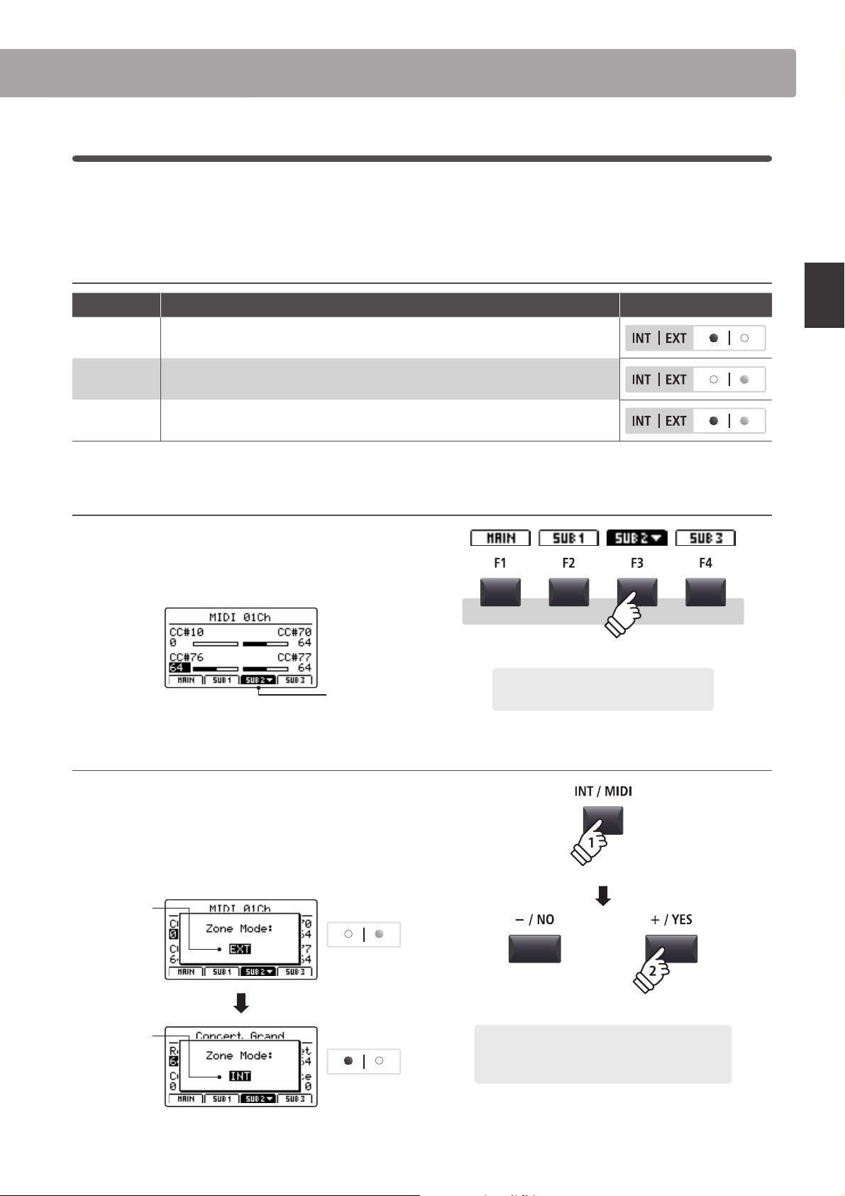
Zone modes
Zone mode Description Panel Appearance
INT The zone will control internal sounds only.
EXT The zone will control external MIDI devices only.
BOTH The zone will control both internal sounds and external MIDI devices simultaneously.
Selecting zones
Press the F1~F4 function buttons located below the LCD display
to select the desired zone.
/
EXT
/
BOTH)
The selected zone will be shown in the LCD display.
SUB2 zone
selected
Changing the zone mode
Press and hold the INT/MIDI button, then press the +/YES or
–/NO buttons to cycle through the dierent zone modes.
The LED indicator for the zone will change to indicate the
selected zone mode, and the Zone Mode pop-up will briey be
shown in the LCD display.
Before:
EXT mode
Zone LED
Example: To select the SUB2 zone, press the
F3 function button.
hold
×2
After:
INT mode
* By defaul t, the MAIN and SUB1 zones will b e set to INT mode, and the SUB2
and SUB3 zones will be set to EX T mode.
Zone LED
Example: To change the SUB2 zone from EXT mode
to INT mode, press and hold the INT/MIDI button,
then press the +/YES button twice.
Page 24
Zone Functions
3
Zone Key Range
By default, the four zones will each utilise all 88-key of the MP7’s keyboard. However, by using the Key Range
function it is possible to create custom keyboard ranges (between two dened keys) for each zone, allowing a
selection of internal sounds or external MIDI devices to be controlled by dierent parts of the keyboard.
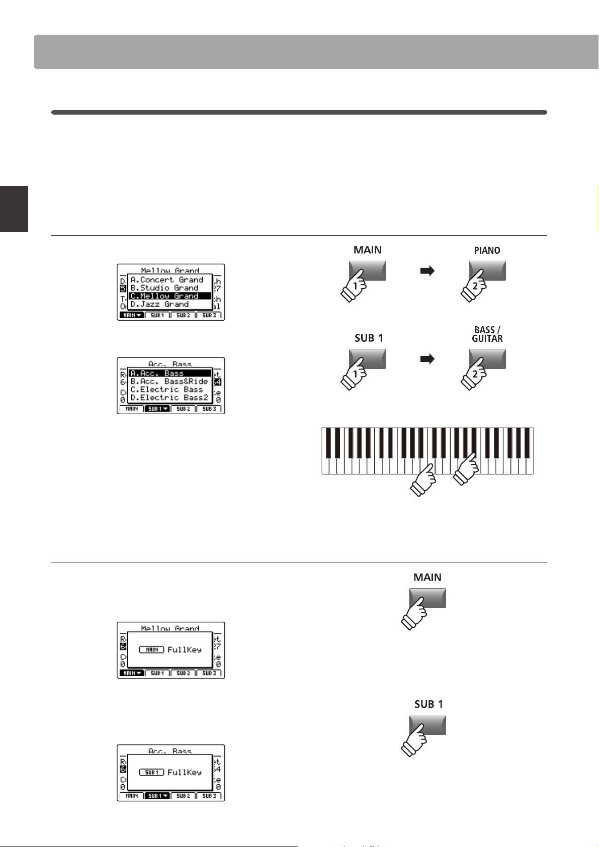
* The example below will explain how to specify key ranges for just the MAIN and SUB1 zones (with a piano sound and acoustic bass sound assigned to the
two zones), however the process is identical for all four zones.
1.SelectingsoundsfortheMAINandSUB1zones
First, turn the MAIN zone ON, then select a piano sound.
Main Operation
Next, turn the SUB1 zone ON, and select a bass sound.
Play the piano.
The piano sound will be layered with the bass sound because
both the MAIN and SUB1 zones are set to use the full keyboard.
The next step is to specify key ranges for the two zones, allowing
the piano and bass sounds to be played independently.
Checking t he zone key range
Press and hold the MAIN button.
The current key range for the MAIN zone will be shown in the
LCD display.
Next, press and hold the SUB1 button.
The current key range for the SUB1 zone will be shown in the
LCD display.
hold
hold
24
Page 25
25
Main Operation
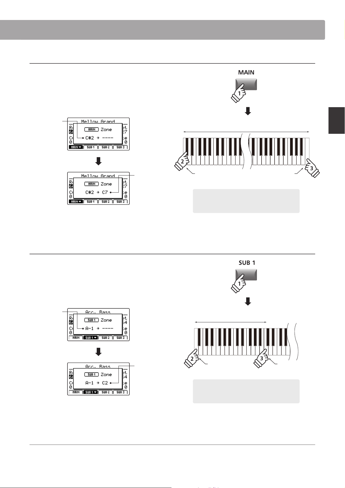
2. Setting the MAIN zone key range
Press and hold the MAIN button, then press the desired low key,
followed by the desired high key for the zone.
The names of the pressed low and high keys will be shown in
the LCD display, and will become the new key range for the
MAIN zone.
Low key:
C#2
hold
Zone key range
High key:
C7
The LED indicator for the MAIN button will also turn green to
indicate that a key range has been set.
3. Setting the SUB1 zone key range
Press and hold the SUB1 button, then press the desired low key,
followed by the desired high key for the zone.
The names of the pressed low and high keys will be shown in
the LCD display, and will become the new key range for the
SUB1 zone.
Low key:
A-1
Low key: C#2
Example: To set the MAIN zone key range between
key C#2 and C7, press and hold the MAIN zone button,
then press the C#2 key, followed by the C7 key.
* It is also possible to set the zone key range using the KeySetup parameters
in the EDIT menu. For more information, please refer to page 45.
hold
Zone key range
High key: C7
High key:
C2
Low key: A-1 High key: C2
Example: To set the SUB1 zone key range between
key A-1 and C2, press and hold the SUB1 zone button,
then press the A-1 key, followed by the C2 key.
The LED indicator for the SUB1 button will also turn green to
indicate that a key range has been set.
* It is also possible to set the zone key range using the KeySetup parameters
in the EDIT menu. For more information, please refer to page 45.
4.PlayingtheMAINandSUB1zonekeyranges
Test the new zone key ranges by playing a chromatic scale from the bottom-most note of the keyboard. The bass sound will be
heard from the bottom-most key to the C2 key, and the piano sound will be heard from the C#2 key to the top-most key. This bass/
piano conguration is a popular combination for playing jazz standards.
Page 26
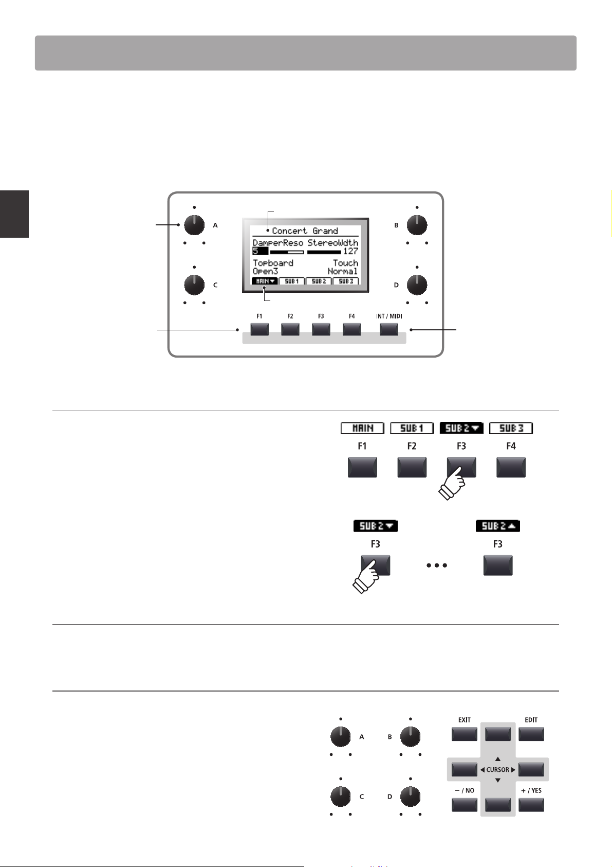
LCD Display & Control Knobs
In regular Play Mode the LCD display provides a visual indication of the selected zone and sound, and the values of
the four real-time control knobs (A, B, C, and D).
The function of each knob can be assigned to control any parameter in the EDIT menu, allowing frequently used
functions to be accessed from a single screen. Furthermore, two groups of knob parameters (2 x 4) can be dened
for each of the MAIN, SUB1, SUB2, and SUB3 zones, providing extensive real-time control.
Selected sound
Control knobs:
Adjust value of assigned
parameters or settings.
Main Operation
Function buttons:
Select zone and various
other operations.
Selecting zones, primary/secondary knob groups
Press the F1~F4 function buttons located below the LCD display
to select the desired zone.
The bottom tab representing the zone will become highlighted,
and the name of the selected sound and primary group of knob
parameters will be shown in the LCD display.
Press the same function button to cycle between the zones’
primary and secondary knob parameters in the LCD display.
* While in the EDIT menu, pressing the same F1~F4 FUNCTION button will
scroll through the dierent parameter pages.
Selected zone/knob group
INT/MIDI button:
Toggle between zone
modes (INT/EXT/BOTH).
Please refer to page 23.
Primary Secondary
Changing zones modes (INT/MIDI button)
For information about changing zone modes, please refer to page 23.
Adjusting parameters
Turn the four control knobs (A, B, C, D) located on either side of
the LCD display to adjust the displayed knob group parameters.
* EDIT menu parameters can be freely assigned to each of the four knobs in
the Knob Assign page of the EDIT menu (page 50).
Parameters can also be adjusted by using the CURSOR buttons
to move the selection cursor, and +/YES or –/NO buttons to
increase or decrease the value of the selected parameter.
26
Page 27
27
Main Operation
Eects Section
1
Reverb
Reverb adds reverberation to the sound, simulating the acoustic environment of a recital room, stage, or concert
hall. The MP7 oers 6 types of high quality reverb, with independent ON/OFF and depth controls for each zone.
The reverb type, pre-delay, and time parameters, however, are common for all zones.
* For more information about common parameters, please refer to page 38.
Reverb types
Reverb type Description
Room Simulates the ambiance of a small rehearsal room.
Lounge Simulates the ambience of a piano lounge.
Small Hall Simulates the ambiance of a small hall.
Concert Hall Simulates the ambiance of a concert hall or theater.
Live Hall Simulates the ambiance of a live hall or stage.
Cathedral Simulates the ambiance of a large cathedral.
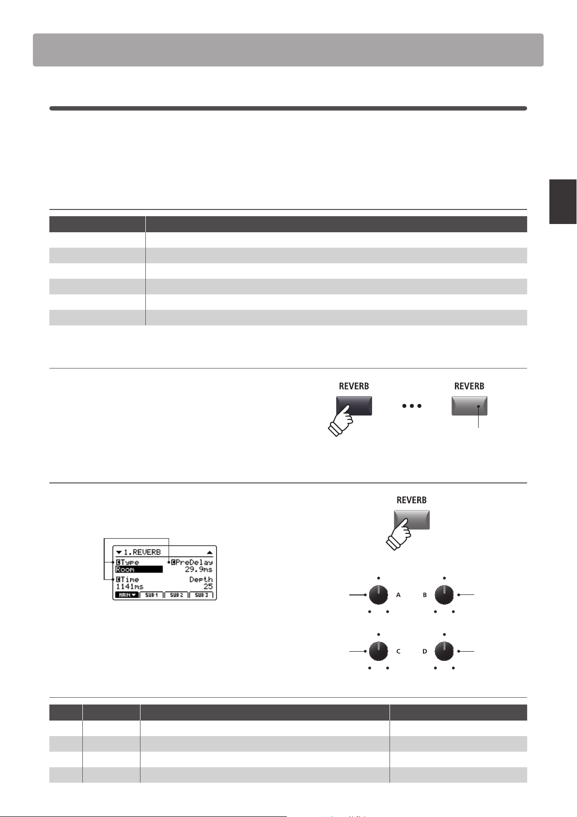
TurningreverbONorOFF
Press the REVERB button for the desired zone to turn reverb for
that zone ON or OFF.
The LED indicator for the zone’s REVERB button will turn ON or
OFF to indicate the current status of the reverb.
Changing the reverb t ype and additional parameters
Press and hold the REVERB button for the desired zone.
The REVERB page of the zone’s EDIT menu will be shown in the
LCD display.
Common
parameters:
See page 38
Turn the four control knobs (A, B, C, D) to change the reverb type
and adjust additional reverb parameters.
Typ e
LED indicator ON:
Reverb is turned ON
hold
PreDelay
Press and hold the REVERB button again to exit.
Reverb parameters
Knob Parameter Description Value range
A Type Changes the type of environment. (see table above)
B PreDelay Adjusts the delay time before the reverberation is applied. 0 ~ 200 ms
C Time Adjusts the decay length/speed of the reverberation. 300 ms ~ 10.0 s
D Depth Adjusts the depth of the environment (amount of reverberation). 0 ~ 127
Time
Depth
(depending on type)
Page 28
Eects Section
2
EFX
In addition to reverb, various other eects can be applied to each zone, altering the tonal character and feeling of
the selected sound. The MP7 features 129 high quality EFX types, with eects automatically applied to some sounds
by default in order to enhance their realism.
As noted in the introduction chapter, the MAIN and SUB1/SUB2/SUB3 zones share largely the same EFX operation,
however there are some important specication and capability dierences between the two zone types.
EFX specications: MAIN and SUB1/SUB2/SUB3 zones
No. of EFX blocks 2 (applied in serial, independently adjustable) 1 each (independently adjustable)
No. of available eects 129 types 22 types
Amp Simulator Yes No
Main Operation
MAIN zone SUB1/SUB2/SUB3 zones
Available eect types: MAIN vs SUB1/SUB2/SUB3 zones
EFX category M S EFX category M S EFX category M S EFX category M S
1 Chorus 8 2 7 Delay/Rev 8 2 13 Groove 4 1 19 Enhancer+ 8 -
2 Flanger 5 2 8 PitchShift 3 1 14 Misc. 2 - 20 P.Shift+ 6 -
3 Phaser 6 1 9 Compressor 2 1 15 Chorus+ 6 - 21 Comp+ 8 -
4 Wah 6 3 10 OverDrive 3 2 16 Phaser+ 6 - 22 OverDrive+ 8 -
5 Tremolo 6 3 11 EQ/Filter 5 2 17 Wah+ 6 - 23 Parallel 6 -
6 AutoPan 4 1 12 Rotary 5 1 18 EQ+ 8 - TOTAL 129 22
* The ‘+’ eects consist of the base eect plus an additional combination eect, while still using only one eect module.
* For more information about available eect categories, types, and parameters, please refer to page 120.
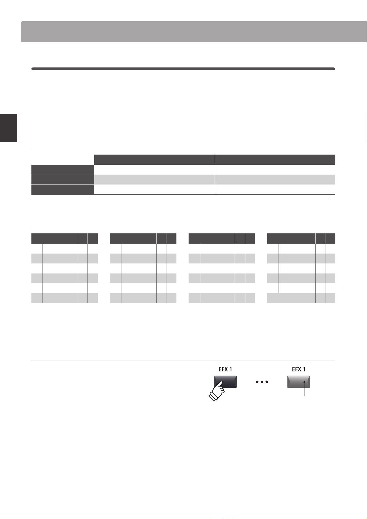
TurningeectsONorOFF
Press the EFX button for the desired zone to turn eects for that
zone ON or OFF.
The LED indicator for the zone’s EFX button will turn ON or OFF
to indicate the current status of the eects.
* The MAIN zone’s EFX1 and EFX2 modules and SUB1/SUB2/SUB3 zones’ EFX
modules are turned ON and OFF in exactly the same way.
LED indicator ON:
Eects are turned ON
28
Page 29
29
Main Operation
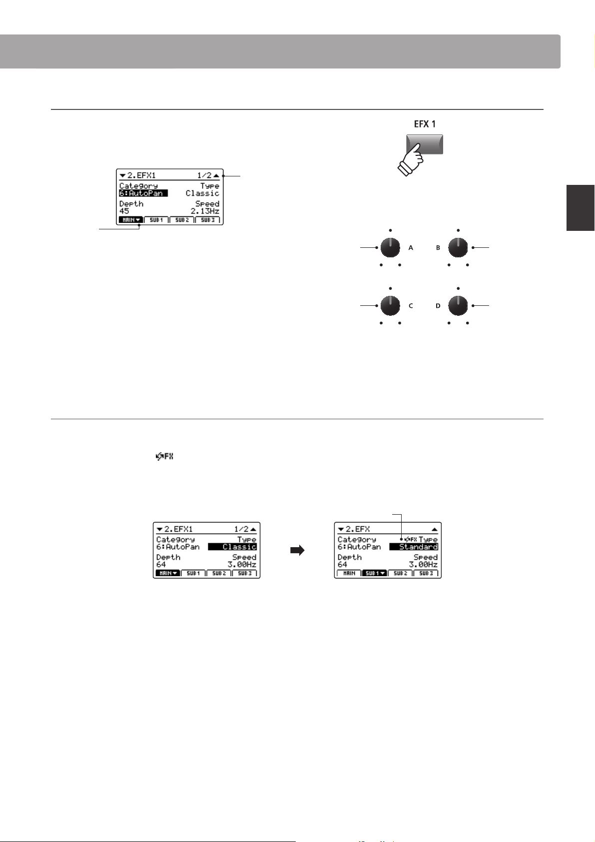
Changing the ee ct category, type and additional parameters
Press and hold the EFX button for the desired zone.
The rst EFX page of the zone’s EDIT menu will be shown in the
LCD display.
Page 1/2
d arrow:
Next page
hold
Category
Typ e
Turn the control knobs (A, B, C, D) to change the eect category,
type, and adjust additional eect parameters.
* The number of adjustable EFX parameters will vary depending on type.
For more information, please refer to page 120.
* Press the F1~F4 FUNCTION buttons (corresponding to the selec ted zone)
to scroll through the dierent parameter pages.
Press and hold the EFX button again to jump to the rst EFX
Parameter 1
* Above knob assignments will change depending on EFX page displayed.
Parameter 2
page of the EDIT menu, and once again to EXIT.
About Substitute eec ts for SUB1/SUB2/SUB3 zones
As noted above, the total number of eect types available for the MAIN zone is much larger than that of the SUB zones. Therefore, when
assigning a sound to a SUB zone that was prepared using an eect only available for the MAIN zone, the MP7 will automatically select the
closest ‘substitute’ eect. An
icon will also be shown beside the type parameter to indicate that a substitute eect is being used.
The example below shows the ‘Classic’ AutoPan eect being substituted for the ‘Standard’ AutoPan eect.
* Only the EFX1 eect will be substituted. Any eects that are assigned to EFX2 will be disregarded.
Substitute eect icon
MAIN zone EFX1 screen
A sound prepared on the
MAIN zone with ‘Classic’
AutoPan eect applied.
SUB1 zoneEFX screen
The same sound assigned
to SUB1 zone, ‘Standard’
AutoPan eect is
automatically substituted.
Page 30
Eects Section
3
Amp Simulator (MAIN zone only)
The tonal character of an amplier or speaker cabinet is an important component of vintage electric piano sounds.
The MP7’s Amp Simulator function features 5 typical amplier types and a selection of adjustable parameters.
Amp types
Amp type Description
S. Case A suitcase type amplier, commonly used for vintage electric piano sounds.
M. Stack A British valve guitar amplier, known for its ‘crunchy’ tonal character.
J. Combo A popular Japanese solid-state amplier favoured for its clean, yet powerful sound.
F. Bass An American valve bass amplier that became popular for guitar, harmonica, and other instruments.
L. Cabi
Main Operation
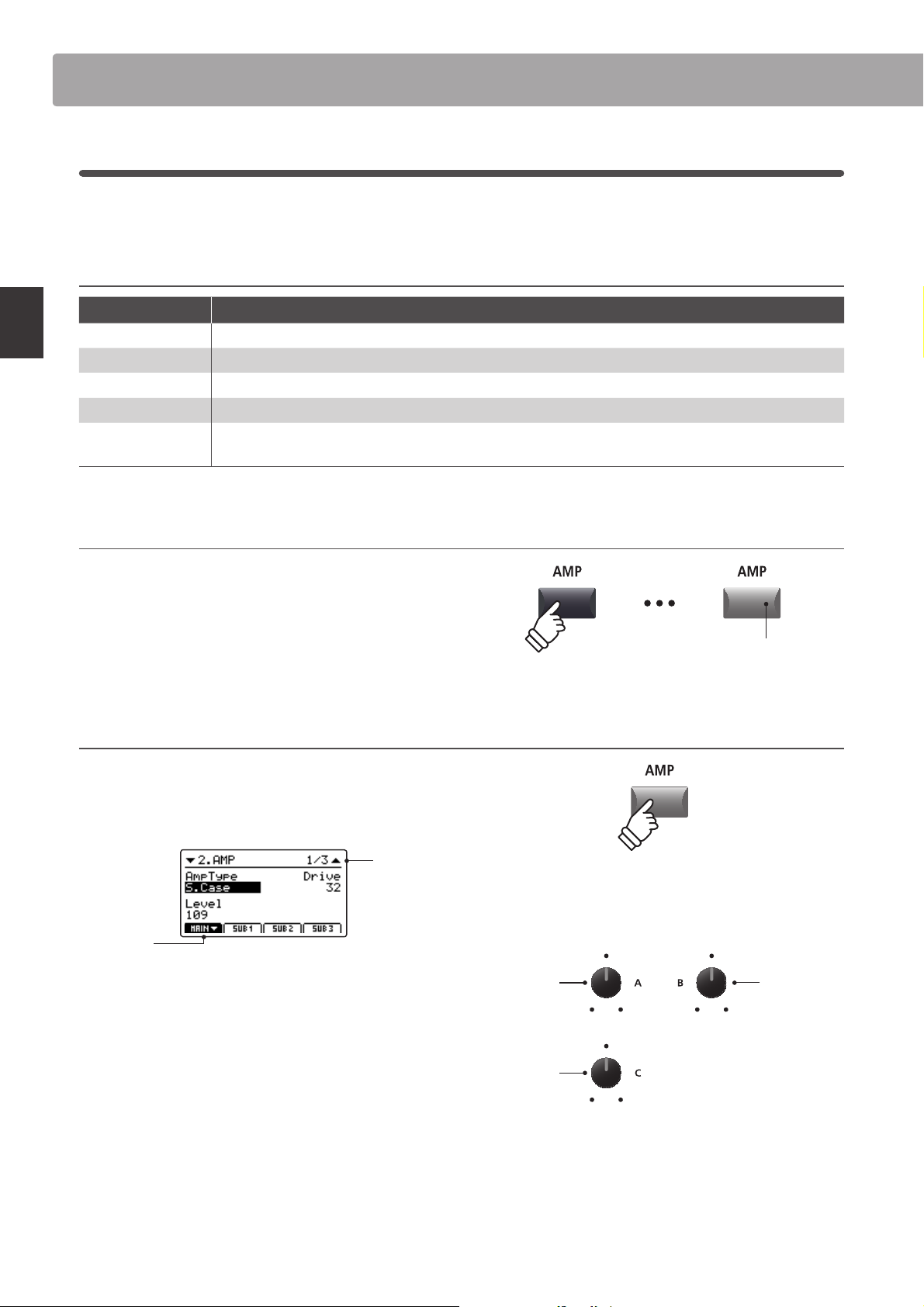
TurningtheAmpSimulatorONorOFF
A valve amplier and speaker enclosed within a wooden cabinet, originally intended for drawbar organ
sounds, but also used with electric pianos to produce a distinctive ‘shimmering’ sound.
Press the MAIN zone’s AMP button to turn the amp simulator
ON or OFF.
The LED indicator for the AMP button will turn ON or OFF to
indicate the current status of the amp simulator.
ChangingtheAmptype,adjustingdrive,andlevelparameters
Press and hold the MAIN zone’s AMP button.
The rst AMP page of the EDIT menu will be shown in the LCD
display.
Page 1/3
d arrow:
Next page
Turn the control knobs (A, B, C) to change the amp type, and
adjust the drive and level parameters.
* For more information about additional Amp Simulator parameters, please
refer to page 41.
* Press the F1 FUNCT ION buttons (corresp onding to the MAIN zone) to scr oll
through the dierent AMP parameter pages.
Amp Type
Level
LED indicator ON:
Amp Simulator is turned ON
hold
Drive
Press and hold the AMP button again to jump to the rst AMP
page of the EDIT menu, and once again to EXIT.
30
* Above knob assignments will change depending on AMP page displayed.
Page 31

31
Main Operation
Amp Simulator parameters
Page Knob Parameter Description Value range
A Amp Type Changes the type of amplier model. [see table above]
1
2
3
B Drive Adjusts the drive level of the amplier. 0 ~ 127
C Level Adjusts the overall volume level of the amplier. 0 ~ 127
A Amp EQ Lo Adjusts the gain of the amplier’s low frequencies. –10 dB ~ +10 dB
B Amp EQ Mid Adjusts the gain of the amplier’s mid frequencies. –10 dB ~ +10 dB
C Amp EQ Hi Adjusts the gain of the amplier’s high frequencies. –10 dB ~ +10 dB
D Mid Frequency Adjusts the frequency of the amplier’s mid-range band. 200 Hz ~ 3150 Hz
A Mic Type Changes the type of microphone used for the amplier. Condenser, Dynamic
B Mic Position Change the position of the microphone used for the amplier. OnAxis, OAxis
C Ambience Adjusts the mixing ratio of additional ambient microphones. 0 ~ 127
Adjusting additional Amp Simulator parameters
Press and hold the MAIN zone’s AMP button, then press the F1
FUNCTION button (corresponding to the selected MAIN zone).
The second AMP page of the EDIT menu will be shown in the
LCD display.
Page 2/3
d arrow:
Next page
Turn the control knobs (A, B, C, D) to adjust the amp simulator’s
Lo, Mid, Hi, and MidFreq EQ parameters.
Press the F1 button again.
The third AMP page of the EDIT menu will be shown in the LCD
display.
hold
Amp EQ Lo
Amp EQ Hi
Amp EQ Mid
Mid Freq.
Page 3/3
d arrow:
Next page
Turn the control knobs (A, B, C) to change the type and
positioning of the amp simulator’s microphone, and adjust the
ambience parameter.
Mic Type
Ambience
Mic Position
Page 32

Tonewheel Organ Mode
The MP7’s tonewheel mode is a special function that transforms the instrument into a vintage electromechanical
organ, complete with drawbar, percussion, and slow/fast rotary speaker controls. Tonewheel mode is only available
for the MAIN zone, and activated when selecting the DRAWBAR sound category and 1, 2, or 3 sub-categories.
Upon activating tonewheel mode and selecting the tonewheel edit screen, the MP7’s zone faders will act as virtual
organ drawbars, with the MAIN, SUB1, SUB2, and SUB3 zone buttons also used to change percussion functions.
1. Activating tonewheel organ mode
After selecting the MAIN zone:
Press the DRAWBAR sound category button, then press either
the 1, 2, or 3 sub-category buttons.
The LED indicators for the pressed buttons will turn ON, and the
selected tonewheel sound will be shown in the LCD display.
Main Operation
Selected
tonewheel
sound
2. Showing the tonewheel edit screen
Press the SW2 button.
The LED indicator for the SW2 button will turn on and the
tonewheel edit screen will be shown in the LCD display.
* The tonewhe el edit screen can als o be shown by selectin g the Sound page
of the EDIT menu when tonewheel mode is activated.
Tonewheel edit sc reen
* The tonewh eel mode can only be s elected for the MAI N zone. When a SUB
zone is selected and the DRAWBAR 1/2/3 buttons are pressed, a pop-up
reminder will be shown and the selected sound will remain unchanged.
* If the assigned function of the SW2 button is changed from the default
‘TW Control’, the tonewheel edit screen will not be shown.
* For information about changing the assigned SW1/SW2 function, please
refer to page 48.
Indicates slow or fast rotary.
Toggled by the SW1 button or
Percussion setting:
Adds percussive ‘attack’ to
the organ sound. Adjusted
using the zone buttons.
32
Rotary speed:
FSW pedal.
Selected tonewheel sound:
Stored to DRAWBAR sounds 1-3, A-D.
Drawbar registration:
Visual representation of the
organ’s drawbar positions.
Adjusted using the zone
faders and control knobs.
* The tonewheel organ drawbars can
also be adjusted via MIDI. For more
information, please refer to page 44.
Selected drawbar group:
Indicates which drawbars will be adjusted using the zone faders and control knobs.
Page 33

33
Main Operation
Adjusting the organ’s drawbar registration
While the tonewheel edit screen is shown in the LCD display, and
the 16’ drawbar group tab is selected:
Use the zone faders to adjust the position of the rst four organ
drawbars.
16’ d rawb ar
group
selected
Turn the control knobs (A, B, C, D) to adjust the position of the
next four organ drawbars.
Finally, press the +/YES or –/NO buttons to adjust the position of
the last organ drawbar.
Changing the selec ted drawbar group
drawbars
adjusted by
zone faders
MAIN:
Drawbar:
Knob A:
2 ⁄’ drawbar
Knob C:
1 ⁄’ drawbar
16’
SUB1:
5 ⁄’
–/NO or +/YES:
SUB2:8’SUB3:
1’ drawbar
4’
Knob B:
2’ drawbar
Knob D:
1 ⁄’ drawbar
Press the F1~F4 function buttons to select which four drawbars
are adjusted by the zone faders.
2’ drawbar
group
selected
Changing organ percussion settings and rotary eect spe ed
While the tonewheel edit screen is shown in the LCD display:
Press the MAIN button to turn percussion ON or OFF, and the
SUB buttons to adjust the percussion characteristics.
Fast rotary
Percussion
enabled
Press the SW1 button or FSW pedal to change the speed of the
rotary eect from slow to fast.
drawbars
adjusted by
zone faders
* The control knob and –/NO and +/YES button drawbar assignments will
change depending on the selected zone faders.
Volu me:
Normal / Soft
Speed:
Slow / Fast
Harmonic:
2nd / 3rd
Page 34

Global Section
1
EQ
The EQ function consists of a 4-band graphic equaliser that can be used to shape the overall tone of the MP7’s
internal sounds. Two of the mid-range frequency bands can also be adjusted as a parametric equaliser.
The equaliser settings are common for all zones.
* For more information about common parameters, please refer to page 38.
TurningEQONorOFF
Press the EQ button to turn the MP7’s equaliser ON or OFF.
The LED indicator for the EQ button will turn ON or OFF to
indicate the current status of the equaliser.
Main Operation
EQ parameters
LED indicator ON:
Equaliser is turned ON
Page Knob Parameter Description Value range
A Low Gain Adjusts the gain of the low range frequency band (20 ~ 100 Hz). –10 dB ~ +10 dB
1
2
Adjusting EQ parameters
Press and hold the EQ button.
The gain page of the EQ will be shown in the LCD display.
B High Gain Adjusts the gain of the high range frequency band (5000 ~ 20000 Hz). –10 dB ~ +10 dB
C Mid1 Gain Adjusts the gain of the Mid1 frequency band (200 ~ 3150 Hz). –10 dB ~ +10 dB
D Mid2 Gain Adjusts the gain of the Mid2 frequency band (200 ~ 3150 Hz). –10 dB ~ +10 dB
A Mid1 Q Adjusts the bandwidth of the Mid1 band. 0.5 ~ 4.0
B Mid2 Q Adjusts the bandwidth of the Mid2 band. 0.5 ~ 4.0
C Mid1 Freq. Adjusts the frequency of the Mid1 band. 200 Hz ~ 3150 Hz
D Mid2 Freq. Adjusts the frequency of the Mid2 band. 200 Hz ~ 3150 Hz
hold
Next
page
Select EQ parameter
Press the CURSOR ef buttons to select the desired EQ
parameter, then press the +/YES or -/NO buttons to increase or
decrease the values.
Alternatively, turn the control knobs (A, B, C, D) to adjust the EQ
parameter assigned to that knob.
* The F1~F4 buttons can also be used to select the desired EQ parameter.
If the parameter is already selected, the F1~F4 buttons can be used to
alternate between the gain and frequency pages of the EQ.
34
Decrease/Increase values
Page 35

35
Main Operation
AdjustingEQparameters(cont.)
While the gain page of the EQ is shown:
Press the CURSOR d button.
The frequency page of the EQ will be shown in the LCD display.
Previous
page
Press the CURSOR ef buttons to select the desired EQ
parameter, then press the +/YES or -/NO buttons to increase or
decrease the values.
Alternatively, turn the control knobs (A, B, C, D) to adjust the EQ
parameter assigned to that knob.
Mid1
bandwidth
Mid1
frequency
Mid2
bandwidth
Mid2
frequency
Press the EXIT button to return to the main playing screen.
Jump to EQ Oset shor tcut
The EQ Oset is a SYSTEM parameter used to oset adjustments made by the EQ. The purpose of the EQ Oset
is to allow a ‘baseline’ EQ to be applied independently of the EQ function, and therefore independently of the
selected SETUP. EQ Oset must be enabled in the SYSTEM menu for this shortcut to function.
* For more information about the EQ Oset function, please refer to page 109.
To jump to the EQ Oset screen, at any time:
Press and hold the EQ button, then press one of the F1~F4
buttons.
The EQ Oset screen will be shown in the LCD display.
Oset
page
hold
The EQ Oset parameters are adjustable in the same manner as
the EQ gain parameters.
* The EQ Oset values will be added to the regular EQ values. The combined
EQ values are limited to ±10 dB.
Press the EXIT button to return to the EQ screen.
Press the EXIT button again to return to the main playing screen.
Page 36

Global Section
2
Transpose
The Transpose function allows the pitch of the MP7’s keyboard to be raised or lowered in semi-tone steps. This is
particularly useful when accompanying instruments tuned for dierent keys, or when a song learned in one key
must be played in another key.
Setting the Transpose value: Method 1
Press and hold the TRANSPOSE button, then press the +/YES
or –/NO buttons to increase or decrease the transpose value in
semi-tone steps.
* The TRANSPOSE value can be adjusted within the range of -24 ~ +24.
Main Operation
hold
The LED indicator for the TRANSPOSE button will turn ON
automatically to indicate that transpose is activated.
* To reset the transpose value to 0 (no transposition), press both the –/NO
and +/YES buttons simultaneously. The LED indicator for the TRANSPOSE
button will turn o automatically.
* The transpose value will be stored to SYSTEM memory automatically,
however the transpose ON/OFF state will not be stored.
Setting the Transpose value: Method 2
Press and hold the TRANSPOSE button, then press a key on the
keyboard to the left or right of middle C.
The pressed key will become the new transpose key.
* The TRANSPOSE value can be adjusted within the range of -24 ~ +24.
Decrease/Increase values
Example: To raise the keyboard pitch by 4 semitones, press and hold the TRANSPOSE button, then
press the +/YES button four times.
hold
-24 0+24
4
×
The LED indicator for the TRANSPOSE button will turn ON
automatically to indicate that transpose is activated.
* To reset the transpose value to 0 (no transposition), press both the –/NO
and +/YES buttons simultaneously. The LED indicator for the TRANSPOSE
button will turn o automatically.
* The transpose value will be stored to SYSTEM memory automatically,
however the transpose ON/OFF state will not be stored.
36
Example: To lower the keyboard pitch by 2 semitones, press and hold the TRANSPOSE button, then
press the Bb key closest to the middle C key.
Page 37

37
Main Operation
Turning Transpose ON or OFF
Press the TRANSPOSE button to turn the transpose function ON
or OFF.
The LED indicator for the TRANSPOSE button will turn ON or
OFF to indicate the current status of the transpose function.
* The previous transpose setting will be remembered after the transpose
function is turned OFF, allowing rapid adjustment of the keyboard pitch.
Checking the Transpose sett ing
Press and hold the TRANSPOSE button.
The current transpose setting will pop-up in the LCD display.
* The default value, 0, indicates no transposition.
LED indicator ON:
Transpose is turned ON
hold
3
Local O
The Local O function allows the connection between the MP7’s keyboard and tone generator to be disabled.
This may be useful when using the MP7 to control an external MIDI device, without the keyboard triggering the
instrument’s internal sounds.
Local function
LOCAL OFF button LED Description
OFF (default) The MP7 will transmit information to external MIDI devices, and play internal sounds.
ON The MP7 will transmit information to external MIDI devices only, and not play internal sounds.
TurningtheLocalfunctionONorOFF
Press the LOCAL OFF button.
The LED indicator for the LOCAL OFF button will turn ON or OFF
to indicate the current status of the Local function.
LED indicator ON:
The Local status pop-up will briey be shown in the LCD display.
Local O is turned ON
Page 38

OverviewoftheEDITMenu(INT mode)
The EDIT menu contains various parameters that can be used to adjust the MP7's MAIN and SUB zones in INT mode.
The parameters are grouped by category, allowing close control over the instrument with just a few button presses.
* The EDIT menu can also be used to adjust the parameters of zones in EXT mode. For more information, please refer to page 54.
This collection of parameters, together with other adjustable settings, can be stored as a SETUP memory (page 64).
The MP7 provides 256 user programmable SETUP memories.
About Common parameters ( icon)
Unless stated, parameter settings for the MAIN, SUB1, SUB2, and SUB3 zones are independent for each zone. However, parameters
marked with a
automatically change the
INT mode zone parameters
No. Category Parameters
icon are common for all four zones. For example, changing the Reverb Type parameter for the MAIN zone will
Reverb Type parameter for the SUB1, SUB2, and SUB3 zones.
EDIT Menu
1REVERB
EFX Category, Type, Parameters
2
AMP Amp Type, Drive, Level, Amp EQ Lo, Amp EQ Mid, Amp EQ Hi, Mid Freq., Mic Type, Mic Position, Ambience
3Sound
4 Tuning Fine Tune, Stretch Tuning, Temperament, Key of Temperament
5 Key Setup
6 Controllers
7Knob Assign
Virtual
8
Technician
Typ e, Pre Delay, Time, Depth
(prm1~prm10, depending on EFX type)
Volume, Panpot, Filter Cut-o, Filter Resonance, DCA Attack Time, DCA Decay Time, DCA Sustain Level,
DCA Release Time, DCF Attack Time, DCF Attack Level, DCF Decay Time, DCF Sustain Level, DCF Release
Time, DCF Touch Depth, DCA Touch Depth, Vibrate Depth, Vibrate Rate, Vibrate Delay, Octave Layer Switch,
Octave Layer Level, Octave Layer Range, Octave Layer Detune, Portamento, Porta. Time, Porta. Mode
TONEWHEEL: Drawbar Position, Percussion, Perc. Level, Perc. Decay, Perc. Harmonic, Volume, Ext. Control
Touch Mode, Touch Curve, Octave Shift, Zone Transpose, Key Range Zone Lo, Key Range Zone Hi,
Velocity Switch, Velocity Switch Value, K.S. Damping, K.S. Key, Dynamics, User Key Volume, Solo, Solo Mode
Damper Pedal,
Modulation Wheel, Modulation Wheel Assign, Modulation Depth Range, SW1 Button,
SW2 Button,
Left Pedal,
Knob A Assign, Knob B Assign, Knob C Assign, Knob D Assign,
Knob2 A Assign, Knob2 B Assign, Knob2 C Assign, Knob2 D Assign
PIANO: Voicing, Stereo Width, String Resonance, Damper Resonance, Key-o Eect, Damper Noise, Hammer
Delay, Fall-back Noise, Topboard
E.PIANO/HARPSI/BASS: Key-o Noise, Key-o Delay
DRAWBAR: Key Click Level, Wheel Noise Level
Damper Pedal Assign, Damper Pedal Mode, Pitch Bend, P. Bend Range, Soft Pedal Depth,
SW1 Button Assign,
SW2 Button Assign, Right Pedal, Right Pedal Assign, Center Pedal, Center Pedal Assign,
Left Pedal Assign, Expression Pedal, Expression Pedal Assign
Entering the EDIT Menu
When the zone is in INT mode:
Press the EDIT button.
The LED indicator for the EDIT button will turn ON, and the Edit
Menu for the selected zone will be shown in the LCD display.
MAIN
zone
selected
38
LED indicator ON:
EDIT mode is turned ON
* To change the selected zone, press the F1~F4 function buttons.
Page 39

Selecting t he parameter category
After entering the EDIT Menu:
Press the CURSOR buttons to select the desired category, then
press the +/YES button to enter the selected category.
Virtual
Technician
selected
Adjusting parameters
After selecting the parameter category:
Turn the four control knobs (A, B, C, D) to adjust the parameters
assigned to those knob.
×3
Example: To enter the Virtual Technician category, press
the CURSORd button three times and the CURSORf
button once, then press the +/YES button.
EDIT Menu
Parameters can also be adjusted by using the CURSOR buttons
to move the selection cursor, and +/YES or –/NO buttons to
increase or decrease the value of the selected parameter.
Press the EXIT button to exit the parameter category, or return
to the Play Mode screen.
Parameter adjustments made to the selected sound will be lost upon selecting another sound.
* To store the adjusted sound, use the STORE button (page 63).
Quick Compare funct ion
The Quick Compare function allows any sound being adjusted to be compared ‘on the y’ with the previously stored (i.e. preset) sound.
While in EDIT mode:
Press the variation button of the sound that is being adjusted.
The LED for the variation button will start to ash, and the
keyboard will play the previously stored sound.
Example: To compare the adjusted Studio Grand
sound with the previously stored version, press
the 'B' sound variation button.
Press the variation button again.
The LED for the variation button will stop ashing, turn ON, and
the keyboard will returning to playing the adjusted sound.
39
Page 40

EDIT Menu parameters (INT mode)
1
Reverb
EDIT Menu
1. Type
This parameter selects the reverb type.
* For more information about reverb, please refer to page 27.
* This parameter is common for all four zones.
* This parameter is not stored to SOUND but to SETUP only.
3. Time
This parameter adjusts the reverb time.
* For more information about reverb, please refer to page 27.
* This parameter is common for all four zones.
* This parameter is not stored to SOUND but to SETUP only.
2
.1 EFX
1. Category
6 TYPES
2. Pre Delay
This parameter adjusts the delay time before the start of the
reverberation.
* For more information about reverb, please refer to page 27.
* This parameter is common for all four zones.
* This parameter is not stored to SOUND but to SETUP only.
4. Depth
This parameter adjusts the reverb depth.
* For more information about reverb, please refer to page 27.
23 CATEGORIES MAIN: 129 TYPES / SUB: 22 TYPES
2. Type
VALU E: 0 ~ 200 MS
VALU E
: 0 ~ 127VALU E: 300 MS ~ 10.0 S
This parameter selects the eect category.
* For more information about eects, please refer to page 28.
* The MAIN zone lists two pages for EFX1 and EFX2.
/A
3. Parameters
These parameters change depending on the selected EFX type,
and are used to adjust the mixing amount of the eected (wet)
and bypassed (dry) sound, depth, speed, feedback, etc.
* For more information about eects, please refer to page 28.
N
This parameter selects the eect type.
* For more information about eects, please refer to page 28.
* The MAIN zone lists two pages for EFX1 and EFX2.
40
Page 41

41
EDIT Menu
2
.2 Amp Simulator (MAIN zone)
1. Amp Type
This parameter selects the simulated amplier type.
* For more information about the various Amp Simulator model types,
please refer to page 30.
3. Level
This parameter adjusts the volume of the simulated amplier.
* For more information about the Amp Simulator, please refer to page 30.
4.AmpEQLo
This parameter adjusts the level of the low frequencies of the
simulated amplier.
* This parameter functions independently of the global EQ.
* For more information about the Amp Simulator, please refer to page 30.
VALU E: –10 dB ~ +10 dB
5
TYPES
VALU E: 0 ~ 127
6.AmpEQHi
2. Drive
This parameter adjusts the amount of overdrive produced by
the simulated amplier.
* For more information about the Amp Simulator, please refer to page 30.
5. Amp EQ Mid
This parameter adjusts the level of the mid frequencies of the
simulated amplier.
* This parameter functions independently of the global EQ.
* For more information about the Amp Simulator, please refer to page 30.
7. Mid Frequency
VALU E: –10 dB ~ +10 dB
VALU E: 200 HZ ~ 3150 HZVALU E: –10 dB ~ +10 dB
VALU E: 0 ~ 127
This parameter adjusts the level of the high frequencies of the
simulated amplier.
* For more information about the Amp Simulator, please refer to page 30.
* This parameter functions independently of the global EQ.
8. Mic Type
This parameter selects the type of microphone used for the
simulated amplier.
Mic Type Description
Condenser
Dynamic
* For more information about the Amp Simulator, please refer to page 30.
10. Ambience
This parameter adjusts the level (mix ratio) of an additional set
of stereo microphones, that are placed away from the simulated
amplier in order to capture the ambient sound within a room.
* For more information about the Amp Simulator, please refer to page 30.
A microphone with a very broad frequency
response that is typically found in studios.
A microphone with a more limited frequency
response that is typically used for live playing.
VALU E
: 0 ~ 127
This parameter adjusts the mid frequency band of the
simulated amplier, levelled by the Amp EQ Mid parameter.
* For more information about the Amp Simulator, please refer to page 30.
* This parameter functions independently of the global EQ.
9. Mic Position
This parameter selects the position of the microphone used for
the simulated amplier.
Mic Position Description
The microphone is placed in the centre of the
On Axis
O Axis
* For more information about the Amp Simulator, please refer to page 30.
speaker, producing a direct, aggressive sound with
strong high/mid range.
The microphone is placed to the side of the speaker,
producing a smoother and more ambient sound.
N AXIS,OFF AXISCONDENSER,DYNAMIC
O
Page 42

EDIT Menu parameters (INT mode)
3
Sound
EDIT Menu
1. Volume
This parameter adjusts the volume level of the selected sound
independently of the zone’s volume fader.
3. Filter Cut-o
This parameter adjusts the frequency of the cut-o. Raising
the cut-o level increases the brightness of the sound, while
lowering the cut-o level results in a duller sound.
5.DCAAttackTime
This parameter adjusts the length of the attack. Higher values
increase the attack time, resulting in a longer, slower attack for
the selected sound.
7. DCA Sustain Level
This parameter adjusts the volume level of the sustain heard
while the key is held for the selected sound.
2. Panpot
This parameter adjusts the left/right position of the selected
sound within the stereo eld.
4. Filter Resonance
This parameter adjusts the amount of the harmonic overtone
around the cut-o frequency for the selected sound.
6. DCA Decay Time
This parameter adjusts the length of the decay from peak level
to sustain level for the selected sound.
8. DCA Release Time
This parameter adjusts the amount of time required for the
sound to fade out after the keys are released for the selected
sound.
VALU E: L64 ~ R63VALU E: 0 ~ 127
VALU E: –64 ~ +63VALU E: –64 ~ +63
VALU E: –64 ~ +63VALU E: –64 ~ +63
VALU E: –64 ~ +63VALU E: –64 ~ +63
9.DCFAttackTime
This parameter adjusts the length of the lter’s attack. Higher
values increase the attack time, resulting in a longer, slower
attack for the lter.
11. DCF Decay Time
This parameter adjusts the length of the decay from peak level
to sustain level for the lter.
13. DCF Release Time
This parameter adjusts the amount of time required for the
lter to fade out after the keys are released.
15.DCATouchDepth
This parameter adjusts how much the velocity aects the
amplitude envelope depth.
VALU E: –64 ~ +63
10. DCF Attack Level
This parameter adjusts the level of the lter’s attack.
12. D CF S ustain Lev el
This parameter adjusts the level of the lter’s sustain heard
while the key is held for the selected sound.
14. DCF Tou ch D epth
This parameter adjusts how much the velocity aects the lter
envelope depth.
VALU E: –64 ~ +63VALU E: –64 ~ +63
VALU E: –64 ~ +63VALU E: –64 ~ +63
VALU E: –64 ~ +63VALU E: –64 ~ +63
42
* With the exception of Volume, the Sound parameters on these pages will
not be available when tonewheel organ mode is selected.
Page 43

43
EDIT Menu
About DCA Parameters
About DCF Parameters
The DCA (Digitally Controlled Amplier) parameters, are used to
adjust the volume level of a sound over time using an envelope.
The diagram below indicates the MP7’s DCA parameters.
Volume
5
6
8
7
Key ON Key OFF
Time
16. Vibrate Depth
This parameter adjusts the depth of the vibration applied to
the selected sound.
The DCF (Digitally Controlled Filter) parameters, are used to
adjust a low-pass lter applied to the sound over time.
The diagram below indicates the MP7’s DCF parameters.
Frequency
9
11
13
10
12
Key ON Key OFF
17. Vibrate Rate
This parameter adjusts the speed of the vibration applied to
the selected sound.
VALU E: –64 ~ +63VALU E: –64 ~ +63
Time
18. Vibrate Delay
This parameter adjusts the delay time before the start of the
vibration.
VALU E: –64 ~ +63
19.OctaveLayerSwitch
This parameter turns the additional Octave Layer ON or OFF.
21.OctaveLayerRange
This parameter sets the amount of octave transposition for the
Octave Layer.
23. Portamento
This parameter turns portamento playing ON or OFF.
Portamento describes the eect of pitch sliding from one note to another.
25.PortamentoMode
20.OctaveLayerLevel
This parameter adjusts the volume level of the Octave Layer.
22.OctaveLayerDetune
This parameter adjusts the tuning of the Octave Layer.
24.PortamentoTime
This parameter adjusts the time required for the portamento
(i.e. the speed of the ‘slide’ between notes).
VALU E
VALU E: 0 ~ 127OFF,ON
: –64 ~ +63VALU E: –2 ~ +2
VALU E: 0 ~ 127OFF,ON
RATE ,EQUAL
This parameter changes the portamento mode.
Portamento Mode Description
Rate The time required for the portamento will be variable. The distance between notes will aect the portamento time.
Equal The time required for the portamento will be constant. The distance between notes will not aect the portamento time.
Page 44

EDIT Menu parameters (INT mode)
3
Sound (MAIN zone, TONEWHEEL mode)
EDIT Menu
1. External Control
This parameter determines whether or not the toneweel organ
drawbars can be adjusted by external MIDI devices. When set
to CC# or MIDI Ch, an additional parameter page will appear,
allowing CC# or MIDI channels to be assigned to each drawbar.
* This is a SYSTEM parameter and therefore memorised automatically. For
more information about SYSTEM parameters, please refer to page 105.
MIDI CC# Drawbar Assign
Knob C:
select
drawbar
Turn control knob C to select the drawbar, and control knob D
to assign the MIDI CC#.
4
Tuning
Knob D:
assign
MIDI CC#
2. MIDI CC#
This parameter sets the CC# used for adjusting tonewheel
organ drawbars when MIDI Control is set to MIDI Ch.
* This is a SYSTEM parameter and therefore memorised automatically. For
more information about SYSTEM parameters, please refer to page 105.
MIDI Ch Drawbar Assign
Knob C:
select
drawbar
Turn control knob C to select the drawbar, and control knob D
to assign the MIDI channel.
VALU E: CC#0 ~ CC#119OFF,MIDICC#MIDICH
VALU E: 01CH ~ 16CHVALU E: CC#0 ~ CC#119
Knob D:
assign
MIDI Ch
1. Fine Tune
This parameter adjusts the tuning of the selected sound for
values smaller than a semi-tone.
3. Temperament
This parameter selects the tuning system of the selected sound.
* For information about creating User Temperaments, please refer to the
User Edit explanation in the SYSTEM menu chapter (page 111).
7
TYPES + 2 USER RANGE: C ~ B
2. Stretch Tuning
This parameter selects the level of stretch tuning.
The human ear typically detects high and low frequencies less accurately
than those frequencies within the middle range. The tuning of an acoustic
piano is therefore ‘stretched’ to compensate, ensuring that the sound will
be heard more naturally to the ears.
9 TYPES + 5 USERVALU E: –64 ~ +63
4.KeyofTemperament
This parameter selects the key of the selected temperament.
When using a temperament other than Equal Temperament,
use this setting to specify the key signature of the piece.
* This parameter will only aect the ‘balance’ of the tuning system, the
pitch of the keyboard will remain unchanged.
44
* With the exception of Fine Tune, the Tuning parameters on these pages
will not be available when tonewheel organ mode is selected.
Page 45

45
EDIT Menu
Temperament types
Temperament type Description
This is the most popular tuning method that divides the scale into twelve equal semi-tones.
Equal Temperament
(Equal)
Pure Temperament
(Pure Maj./Pure Min.)
Pythagorean Temperament
(Pythagorean)
Meantone Temperament
(Meantone)
Werkmeister III Temperament
(Werkmeis)
Kirnberger III Temperament
(Kirnberg)
User Temperament
(Sys.User1/2)
* For information about creating User Temperaments, please refer to the User Edit explanation in the SYSTEM menu chapter (page 111 ).
This produces the same chordal intervals in all twelve keys, and has the advantage of limitless
modulation of the key. However, the tonality of each key becomes less characteristic and no chord is in
pure consonance.
This temperament, which eliminates dissonances for thirds and fths is still popular for choral music
because of its perfect harmony.
When playing in a major key select ‘Pure Maj’ and when playing in a minor key select ‘Pure Min’.
This temperament, which uses mathematical ratios to eliminate dissonance for fths, is very limited for
use with chords, but it produces very characteristic melodic lines.
This temperament, which uses a mean between a major and minor whole tone to eliminate dissonance
for thirds, was devised to eliminate the lack of consonances experienced with certain fths for the
Mersenne pure temperament.
It produces chords that are more beautiful than those with the equal temperament.
These two temperaments are placed in between Meantone and Pythagorean. For music with few
accidentals, this temperament produces the beautiful chords of the mean tone, but as accidentals
increase, the temperament produces the characteristic melodies of the Pythagorean temperament.
They are used primarily for classical music written in the Baroque era to revive the original characteristics.
User dened temperament created by raising or lowering the pitch for each semi-tone.
5
Key Setup
1. Touch Mode
This parameter selects the trigger point for the keyboard.
A fast/higher trigger point may be useful when playing sounds that are
traditionally played on non-weighted keyboards such as organ or synth.
Touch Mode Description
Normal The keyboard trigger point is normal.
O-Fast The keyboard trigger point is earlier than Normal.
O-Fast2 The keyboard trigger point is earlier than O-Fast.
* When either fast mode is selected, touch response will be disabled.
* This parameter is common for all four zones.
3. Octave Shift
This parameter adjusts the amount of octave transposition for
the selected sound.
NORMAL,OFF-FAST,OFF -FAST2
VALU E: –3 ~ +3 OCTAVES
2. Touch Curve
This parameter selects the touch response curve of the
keyboard for the selected sound.
* For more information about touch curve types, please refer to page 46.
* For information about creating User Touch Curves, please refer to the
User Edit explanation in the SYSTEM menu chapter (page 110).
* This parameter will not be available when tonewheel organ mode is
selected.
4. Zone Transpose
This parameter adjusts the amount of transposition for the
selected zone.
6 TYPES + 5 USER
VALU E
: –12 ~ +12
5.KeyRangeZoneLo
This parameter denes the bottom key of the selected zone.
* For more information about adjusting the zone key range, please refer
to page 24.
RANGE: A-1 ~ C7 RANGE: A-1 ~ C7
6.KeyRangeZoneHi
This parameter denes the top key of the selected zone.
* For more information about adjusting the zone key range, please refer
to page 24.
Page 46

EDIT Menu parameters (INT mode)
5
Key Setup (cont.)
Touch Cur ve t ypes
Touch Curve No. Description
EDIT Menu
Light +
Light
Normal Reproduces the standard touch sensitivity of a typical acoustic piano.
Heavy
Heavy + Requires considerably more striking force to achieve a loud volume.
O
(constant)
User* (User 1~User 5) – A custom touch curve, created to suit an individual’s personal playing style.
* For information about creating User touch cur ves, please refer to the User Edit explanation in the SYSTEM menu chapter (page 110 ).
Touch Curve graph
The illustration below provides a visual representation of the
dierent Touch Curve types.
Requires less striking force to achieve a forte note.
* This touch cur ve is intended for players with a very delicate touch.
A louder volume is produced even when playing with a soft touch.
* This touch curve is intended for players who are still developing nger strength.
Requires a heavier touch to produce a loud volume.
* This touch cur ve is intended for players with stronger ngers.
A constant volume is produced regardless of how hard the keys are struck.
* This touch cur ve is intended for playing sounds of instruments that have a xed dynamic range (e.g. harpsichord).
Dynamics graph
The illustration below provides a visual representation of the
Dynamics parameter.
Dynamics = OFF
Loud
Sound Volume
Soft
Gentle Strong
Keyboard Pressure
Loud
Sound Volume
Soft
Dynamics = 5
Dynamics = 10
Gentle Strong
Keyboard Pressure
46
Page 47

47
EDIT Menu
5
Key Setup (cont.)
7/8. Velocity Switch
These parameters enable velocity switching, and set the velocity switch type and value.
Velocity Switching is useful when combining multiple zones, allowing dierent sounds to be played depending on the velocity of the key strike.
Switch Mode Description
O The selected sound will play normally (i.e. no velocity switching).
Soft The selected sound will play only when the velocity is lower than the dened velocity switch value.
Loud The selected sound will play only when the velocity is higher than the dened velocity switch value.
Sound Volume
Velocity Switch O
Sound Volume
Keyboard Velocity
Velocity Switch Soft
Non-sound rangeSound range
Velocity Switch value
Keyboard Velocity
MODE:OFF,SOFT,LOUD / VALU E: 0 ~ 127
Velocity Switch Loud
Velocity Switch value
Sound rangeNon-sound range
Sound Volume
Keyboard Velocity
9. Key Scaling Damping
This parameter determines whether or not damping (velocity
reduction) should be applied to a sound over a specic range.
This parameter may be useful when layering a piano sound with a strings
sound, in order to reduce the level of the strings in the higher key range.
11. Dynamics
This parameter adjusts the keyboard response (velocity
compression) of the selected sound independently of the
touch curve.
When the value is 10 (default), the keyboard response is normal. As the
value decreases the keyboard response gradually becomes less dynamic,
and when set to OFF becomes completely at (i.e. xed touch response).
* For more information about dynamics, please refer to page 46.
VALU E:OFF, 1 ~ 10
13. Solo
This parameter determines whether or not playing will be
restricted to single notes, even when more than one note is
played simultaneously.
This parameters can be used to eectively simulate the performance
characteristics of a monophonic synthesizer.
ON,OFF RANGE: A-1 ~ C7
ON,OFF
10. Key Scaling Key
This parameter denes the point on the keyboard from which
Key Scaling Damping should be applied, up to the highest key.
12.UserKeyVolume
This parameter selects the User Key Volume memory for the
selected sound section, if desired.
* For information about creating User Key Volumes, please refer to the User
Edit explanation in the SYSTEM menu chapter (page 112).
14. Solo Mode
This parameter selects the solo mode for the selected zone.
Solo Mode Description
Last Play the last note of a group of notes.
High Play the highest note of a group of notes.
Low Play the lowest note of a group of notes.
FF, 5 USER
O
LAST, HIGH,LOW
* The Key Setup parameters on this page will not be available when tonewheel organ mode is selected.
Page 48

EDIT Menu parameters (INT mode)
6
Controllers
EDIT Menu
1. Damper Pedal
This parameter determines whether or not the included F-10H
damper pedal is active for the selected sound.
* For more information about connecting pedals, please refer to page 17.
3. Damper Pedal Mode
This parameter determines whether or not the damper pedal
should sustain sounds indenitely without decay.
4. Pitch Bend
This parameter determines whether or not the pitch bend
wheel is active for the selected sound.
6. Soft Pedal Depth
ON,OFF
ORMAL, HOLD
N
ON,OFF VALU E: 0 ~ 7
: 1 ~ 10
VALU E
2. Damper Pedal Assign
This parameter selects the function assigned to the included
F-10H damper pedal.
* This parameter is common for all four zones.
28 FUNCTI ONS (MAIN)
18
FUNCTI ONS (SUB)
5. Pitch Bend Range
This parameter sets the range of the pitch bend wheel in semitone steps.
* The range diers for INT mode (0 ~7) and EXT mode (0~12).
This parameter adjusts the eectiveness (i.e. depth/strength)
of the soft pedal.
7. Modulation Wheel
This parameter determines whether or not the modulation
wheel is active for the selected sound.
9. Modulation Depth Range
This parameter sets the range of the pitch modulation function
in steps of 600/127 cents.
10. SW1 Button
This parameter determines whether or not the SW1 button is
active for the selected sound.
O
N,OFF
VALU E: 0 ~ 127
N,OFF 10 FUNCTIO NS
O
8. Modulation Wheel Assign
This parameter selects the function assigned to the MP7’s
modulation wheel.
28 FUNCTI ONS (MAIN)
18
FUNCTI ONS (SUB)
11. SW1 Button Assign
This parameter selects the function assigned to the SW1
button.
* This parameter is common for all four zones.
12. S W2 B ut ton
This parameter determines whether or not the SW2 button is
active for the selected sound.
48
ON,OFF 10 FUNCTI ONS
13. SW2 Button Assign
This parameter selects the function assigned to the SW2
button.
* This parameter is common for all four zones.
Page 49

49
EDIT Menu
6
Controllers (cont.)
14.RightPedal
This parameter determines whether or not the right pedal of
the optional F-30 pedal unit is active for the selected sound.
* For more information about connecting pedals, please refer to page 17.
O
N,OFF
16.CenterPedal
This parameter determines whether or not the centre pedal of
the optional F-30 pedal unit is active for the selected sound.
* For more information about connecting pedals, please refer to page 17.
18.LeftPedal
This parameter determines whether or not the left pedal of the
optional F-30 pedal unit is active for the selected sound.
* For more information about connecting pedals, please refer to page 17.
ON,OFF
15. Right Pedal Assign
This parameter selects the function assigned to the right pedal
of the optional F-30 pedal unit.
* This parameter is common for all four zones.
17.CenterPedalAssign
This parameter selects the function assigned to the centre
pedal of the optional F-30 pedal unit.
* This parameter is common for all four zones.
19. Left Pedal Assign
This parameter selects the function assigned to the left pedal
of the optional F-30 pedal unit.
* This parameter is common for all four zones.
28 FUNCTI ONS (MAIN)
18
FUNCTI ONS (SUB)
FUNCTI ONS (MAIN)
28
18
FUNCTI ONS (SUB)ON,OFF
28 FUNCTI ONS (MAIN)
18
FUNCTI ONS (SUB)
20.ExpressionPedal
This parameter determines whether or not the expression
pedal (if connected) is active for the selected sound.
* For more information about connecting pedals, please refer to page 17.
Assignable pedal/mod. wheel functions
Function
Modulation
Panpot
Expression
Damper
Sostenuto
Soft
Resonance
Cut-o
EFX1 Parameter 1 ~ 10, EFX2 Parameter 1 ~ 10 (
EFX Parameter 1 ~ 10 (
SUB)
MAIN)
ON,OFF
21. Expression Pedal Assign
This parameter selects the function assigned to the expression
pedal (if connected).
* This parameter is common for all four zones.
Assignable SW1/SW2 button functions
Function
Octave Layer
Rotary Slow/Fast
Solo
Portamento
Pitch Bend Lock
Modulation Wheel Lock
Center Pedal Lock
Left Pedal Lock
Expression Pedal Lock
Tonewheel Control
28 FUNCTI ONS (MAIN)
18
FUNCTI ONS (SUB)
Page 50

EDIT Menu parameters (INT mode)
7
Knob Assign
The Knob Assign screen is used to assign EDIT menu parameters to the four main control knobs A, B, C, and D
for direct, real-time adjustment in Play Mode. Two groups of knob parameters (primary and secondary) can be
assigned to each of the four zones, providing extensive control over the selected sounds.
Assigningparameterstoeachknob
Enter the Knob Assign screen for the desired section.
Turn the four control knobs (A, B, C, D) to spe cify which parameter
should be assigned to each control knob in Play Mode.
Parameters can also be assigned by using the CURSOR buttons
to move the selection cursor, and +/YES or –/NO buttons to
cycle through the available parameters.
Page 1/2
EDIT Menu
d arrow:
Next page
Press the F1~F4 function buttons (depending on the selected
zone) or CURSOR cd buttons to show the secondary group of
knob parameters in the LCD display.
Page 2/2
* Assignable parameters dier slightly for each sound section. For a full list
of assignable parameters, please refer to the page 51.
* For more information about adjusting parameters in Play Mode, please
refer to page 26.
About EFX paramete r p laceholder names (EFX Para1~10)
Some EFX oer a wide range of available parameters, while other s are less exible and feature fewer adjustable parameters. When assigning
EFX parameters to the four control knobs, the names of the available parameters for the selected EFX (e.g. Wah:LowEQ) will be shown.
If the selected EFX features a smaller number of available parameters, a placeholder name (e.g. ‘EFX Para 5’) will be substituted in the Knob
Assign menu, and the knob will become inactive in the main play screen.
Knob Assign screen
ClassichTch Wah selected,
LowEQ parameter assigned
to control knob D.
Knob Assign screen
LpfPdl Wah selected,
control knob D changes to
EFX Para5 parameter
(i.e. inactive).
ClassichTch Wah selected,
control knob D shows
Wah:LowEQ p arameter.
50
Play screen
Play screen
LpfPdl Wah selected,
control knob D changes to
EFX Para5 (i.e. inactive).
Page 51

51
EDIT Menu
Assignable control knob parameters
Parameter Name
Rev.Type
RevPreDly
Rev.Time
1. REVERB
Rev.Depth
EFX Categ.
EFX Type
EFX Para1
EFX Para2
EFX Para3
EFX Para4
EFX Para5
EFX Para6
EFX Para7
EFX Para8
EFX Para9
EFX Para10
EFX2 Categ.
EFX2 Type
EFX2 Para1
EFX2 Para2
EFX2 Para3
EFX2 Para4
2. EFX/AMP
EFX2 Para5
EFX2 Para6
EFX2 Para7
EFX2 Para8
EFX2 Para9
EFX2Para10
Amp Type
Amp Level
Amp Drive
AmpEQ-Lo
AmpEQ-Mid
AmpEQ-High
MidFreq.
AmpMicType
AmpMicPos.
AmpAmbien.
Volume
Panpot
Cuto
Resonance
DCA Attack
DCA Decay
DCASustain
DCARelease
DCF ATK Tm
DCF ATK Lv
DCF Decay
DCFSustain
DCFRelease
DCF TchDpt
3. Sound
DCA TchDpt
Vib.Depth
Vib.Rate
Vib.Delay
Octave
Oct.Level
Oct.Range
Oct.Detune
Portament
Porta.Time
Porta.Mode
Sound Type
Piano E.Piano T.Wheel Others
z
z
z
zzzz
zzzz
zzzz
zzzz
zzzz
zzzz
zzzz
zzzz
zzzz
zzzz
zzzz
zzzz
zzzz
zzzz
zzzz
zzzz
zzzz
zzzz
zzzz
zzzz
zzzz
zzzz
zzzz
zzzz
zzzz
zzzz
zzzz
zzzz
zzzz
zzzz
zzzz
zzzz
zzzz
zzzz
zzzz
zzzz
zz
zz
zz
zz
zz
zz
zz
zz
zz
zz
zz
zz
zz
zz
zz
zz
zz
zz
zz
zz
zz
zz
zz
zz
-
-
-
-
-
-
-
-
-
-
-
-
-
-
-
-
-
-
-
-
-
-
-
-
z
z
z
z
z
z
z
z
z
z
z
z
z
z
z
z
z
z
z
z
z
z
z
z
Parameter Name
Fine Tune
Stretch
Temperment
4. Tuning
Temper.Key
Piano E.Piano T.Wheel Others
zzzz
zz
zz
zz
Touch Mode
Touch
OctavShift
ZoneTrans.
Zone Lo
Zone Hi
VeloSW
VeloSW Val
5. Key Setup
KS-Damping
KS-Key
Dynamics
Solo
SoloMode
DamperPed.
zz
zzzz
zzzz
zzzz
zzzz
zz
zz
zz
zz
zz
zz
zz
zzzz
D.Assign
SoftPdlDpt
Damp.Mode
Pitch Bend
Bend Range
Mod.Wheel
Mod.Assign
SW1
zz
zzzz
zz
zz
zzzz
zzzz
zzzz
SW1Assign
SW2
6. Control
SW2Assign
Right Ped.
zzzz
zzzz
R.Assign
CenterPed.
zzzz
C.Assign
Left Pedal
zzzz
L.Assign
EXP Pedal
zzzz
EXPAssign
Voicing
StereoWdth
StringReso
DamperReso
KeyOE.
DamperNois
HammerDly
FallbackNs
Topboard
8. Virtual Technician
KeyONois -
z
z
z
z
z
z
z
z
z
KeyODly Key Click - Wheel Noise - -
Sound Type
-
-
-
z
-
-
-
-
-
-
-
-
z
-
-
-
z
z
z
z
z
z
z
z
z
z
z
z
z
z
z
z
z
z
z
z
---
---
---
---
---
---
---
---
---
z
z
--
--
z
z
-
-
* EFX2 and Amp Simulator parameters available for MAIN zone only.
* E.Piano ‘Key O Noise’ and ‘Key O Delay’ parameters also apply to
Harpsichord and Bass sounds.
Page 52

EDIT Menu parameters (INT mode)
8
Virtual Technician (PIANO sounds)
EDIT Menu
1. Voicing
This parameter attempts to recreate the technique of adjusting the action, hammers and strings of an acoustic piano, allowing the
tonal character and dynamics of the MP7’s piano sounds to be dramatically altered.
Voicing types
Voicing Type Description
Normal The normal tonal character of an acoustic piano throughout the entire dynamic range.
Mellow 1 A softer, more mellow tonal character throughout the entire dynamic range.
Mellow 2 An even soften tonal character than Mellow 1.
Dynamic A tonal character that changes dramatically from mellow to bright, depending on the strength of key strike.
Bright 1 A bright tonal character throughout the entire dynamic range.
Bright 2 An even brighter tonal character than Bright 1.
2. Stereo Width
This parameter adjusts the width of the stereo sound.
VALU E: 0 ~ 127 VALU E:OFF, 1 ~ 10
3. String Resonance
This parameter adjusts the volume of the string resonance.
String Resonance refers to a phenomenon that exists in acoustic pianos
whereby the strings of held notes resonate ‘sympathetically’ with other
notes of the same harmonic series.
6
TYPES
4. Damper Resonance
This parameter adjusts the volume of the damper resonance.
Depressing the damper pedal of an acoustic piano raises all dampers,
allowing the strings to vibrate freely. When a note or chord is played on
the piano with the sustain pedal depressed, not only will the strings of
the notes played vibrate, but also the strings of other notes, vibrating in
sympathetic resonance.
6. Damper Noise
This parameter adjusts the volume of the damper noise.
When the damper pedal is depressed and released, it is often possible to
hear the sound of the damper head touching and releasing the strings.
8. Fall-back Noise
This parameter adjusts the volume of the noise heard when the
keyboard action ‘falls back’ after a key is released.
VALU E:OFF, 1 ~ 10 VALU E:OFF, 1 ~ 10
VALU E:OFF, 1 ~ 10 VALU E:OFF, 1 ~ 10
VALU E:OFF, 1 ~ 10 CLOSE,OPEN1, OPEN2, OPEN3
52
5. Key-o Eect
This parameter adjusts the volume of the key-o eect.
When playing an acoustic piano – particularly in the bass region of the
keyboard – if a key is played with force and released quickly, it is often
possible to hear the faint sound of the damper touching the strings
immediately before the vibrations are stopped.
7. Hammer Delay
This parameter adjusts the delay of the hammer striking the
string when playing with pianissimo.
9. Topboard
This parameter changes the position of the piano’s topboard.
When playing an acoustic grand piano, the position of the instrument’s
topboard (lid) aects both the volume and ‘openness’ of the tone
produced. A fully open topboard allows sound waves to reect o the
polished lid surface and project into the room, while a closed lid has the
opposite eect, resulting in a darker, more opaque tone.
Page 53

53
EDIT Menu
Virtual Technician (E.PIANO, HARPSICHORD, BASS sounds)
1. Key-o Noise
When an E.PIANO category sound is selected, this parameter
adjusts the volume of the noise heard when the keys of an
electromechanical instrument are released.
When a harpsichord or bass sound is selected this parameter
adjusts the volume of the release noise for harpsichord and
bass sounds.
VALU E:OFF, 1 ~ 127 VALU E: 0 ~ 127
Virtual Technician (DRAWBAR sounds)
1. Key Click Level
This parameter adjusts the volume of the key click sound when
playing drawbar organ sounds.
VALU E:OFF, 1 ~ 127 VALU E: 0 ~ 127
2. Key-o Delay
This parameter adjusts the delay time before the Key-o Noise
is heard.
2.WheelNoiseLevel
This parameter adjusts the volume of the ambient noise
produced by the organ’s spinning tonewheels.
Increase the value of this parameter to give the tonewheel organ a more
vintage character.
Page 54

OverviewoftheEDITMenu(EXT mode)
The EDIT menu can also be used to adjust parameters for zones in EXT mode. As with the INT mode EDIT menus,
the parameters are grouped by category, providing direct control over any connected MIDI devices.
As with zones set to INT mode, this collection of parameters, together with other adjustable settings, can be stored
as a SETUP memory (page 64). The MP7 provides 256 user programmable SETUP memories.
AboutCommonparameters( icon)
Unless stated, parameter settings for the MAIN, SUB1, SUB2, and SUB3 zones are independent for each zone. However, parameters
marked with a
will automatically change the
About System parameters ( icon)
EXT mode zone parameters marked with a icon are SYSTEM parameters and memorised automatically, without the need to use
the STORE function.
icon are common for all four zones. For example, changing the Right Pedal Assign parameter for the MAIN zone
Right Pedal Assign parameter for the SUB1, SUB2, and SUB3 zones.
EDIT Menu
EXTmodezoneparameters
No. Category Parameters
1 Channel/Program MIDI Transmitting Channel, Program, Bank MSB, Bank LSB
2 SETUP Send Program, Send Bank, Send Volume, Send Knobs
3
Transmit
4
MMC
5 Key Setup
6 Controllers
7Knob Assign
Entering the EDIT Me nu
When the zone is in EXT mode:
Transmit System Exclusive, Transmit Recorder
Transmit MMC, MMC Device ID, MMC Commands
Touch Mode, Touch Curve, Octave Shift, Zone Transpose, Key Range Zone Lo, Key Range Zone Hi,
Velocity Switch, Velocity Switch Value, Key Scaling Damping, Key Scaling Key, Dynamics, Solo,
Solo Mode, Transmit Keyboard
Damper Pedal,
Pitch Bend Range, Modulation Wheel, Modulation Wheel Assign, Right Pedal,
Center Pedal,
Expression Pedal Assign
Knob A Assign, Knob B Assign, Knob C Assign, Knob D Assign,
Knob2 A Assign, Knob2 B Assign, Knob2 C Assign, Knob2 D Assign
Damper Pedal Assign, Half Pedal Values, Modulation Depth Range, Pitch Bend,
Center Pedal Assign, Left Pedal, Left Pedal Assign, Expression Pedal,
Right Pedal Assign,
Press the EDIT button.
The LED indicator for the EDIT button will turn ON, and the Edit
Menu for the selected zone will be shown in the LCD display.
MAIN
zone
selected
54
LED indicator ON:
EDIT mode is turned ON
* To change the selected zone, press the F1~F4 buttons.
Page 55

55
EDIT Menu
Selecting t he parameter category
After entering the EDIT Menu:
Press the CURSOR buttons to select the desired category, then
press the +/YES button to enter the selected category.
MMC
selected
Adjusting parameters
×3
Example: To enter the MMC category, press the CURSORd
button three times, then press the +/YES button.
After selecting the parameter category:
Turn the four control knobs (A, B, C, D) to adjust the parameters
assigned to those knob.
Parameters can also be adjusted by using the CURSOR buttons
to move the selection cursor, and +/YES or –/NO buttons to
increase or decrease the value of the selected parameter.
Press the EXIT button to exit the parameter category, or return
to the Play Mode screen.
Page 56

EDIT Menu parameters (EXT mode)
1
Channel/Program
EDIT Menu
1. MIDI Transmitting Channel
This parameter determines which MIDI channel will be used to
transmit event information for the selected zone.
* By default, SUB2 and SUB3 zones are assigned MIDI channels 01 and 02.
MAIN and SUB1 zones are assigned MIDI channels 03 and 04.
* The specied MIDI transmit channel should match the MIDI Receive
channel of the connected MIDI device.
3/4. Bank MSB/Bank LSB
This parameter determines which MSB and LSB number will
be transmitted when a SETUP is recalled. The MIDI standard
allocates 128 storage spaces, however this number can be
expanded using an MSB and an LSB.
The diagram to the right illustrates how the Program Number,
MSB Bank, and LSB Bank are organised.
* Please refer to the owner’s manual of the connected MIDI device for
further information.
VALU E: 01CH ~ 16CH
VALU E: 0 ~ 127
2. Program
This parameter determines which Program Change Number
will be transmitted when a SETUP is recalled. For example,
the desired Program number of a sound on the external MIDI
device.
LSB Bank
Program Number
VALU E: 1 ~ 128
MSB Bank
2
SETUP
1. Send Program
This parameter determines whether or not a Program Change
Number will be transmitted when a SETUP is recalled.
To change sounds on external MIDI devices when recalling a SETUP, set
this parameter to ON.
3. Send Volume
This parameter determines whether or not an initial MIDI
Volume message will be transmitted when a SETUP is recalled.
* Adjusting the volume of a zone by turning the control knobs will still
transmit values even if this parameter is set to OFF.
SETUPparametersintheSYSTEMmenu
The above Send parameters can be overridden by the SETUP
Program, SETUP Bank, SETUP Volume, SETUP Knobs parameters
in the MIDI category of the SYSTEM menu (page 108).
When these SETUP
shown beside the relevant Send parameter to indicate that the
EDIT menu setting is being overridden.
parameters are set to OFF, an asterisk will be
56
ON,OFF
ON,OFF
2. Send Bank
This parameter determines whether or not Program Bank
Numbers (MSB, LSB) will be transmitted when a SETUP is
recalled.
If the external MIDI device requires a Bank Select message, set this
parameter to ON.
4. Send Knobs
This parameter determines whether or not control knob
settings will be transmitted (ON) or not (OFF) when a SETUP
is recalled.
* Turning the control knobs will still transmit values even if this parameter
is set to OFF.
Asterisk:
Parameter is
overridden by
SETUP menu
ON,OFF
ON,OFF
Page 57

57
EDIT Menu
3
Transmit
The Transmit category parameters are all SYSTEM parameters. These parameters are memorised automatically and
therefore do not need to be stored to each SETUP.
1. Transmit System Exclusive
This parameter determines whether or not System Exclusive
(SYSEX) data will be transmitted to an external MIDI device.
* For more information about System Exclusive data transmitted by the
MP7, please refer to page 132.
4
MMC
The MMC category parameters are all SYSTEM parameters. These parameters are memorised automatically and
therefore do not need to be stored to each SETUP.
1. Transmit MMC
This parameter determines whether or not the MP7’s recorder
control buttons will transmit MMC (MIDI Machine Control)
data.
ON,OFF ON,OFF
ON,OFF VALU E: 0 ~ 127
3. MMC Commands
2. Transmit Recorder
This parameter determines whether or not data will be
transmitted to an external MIDI device when playing internal
recorder songs.
2. MMC Dev. ID
This parameter determines the device ID of the MMC (MIDI
Machine Control).
MMC COMMANDS, 3 REALTIME COMMANDS
13
These parameters allow MMC or Realtime commands to be assigned to the MP7’s six recorder control buttons.
* By default, the main MMC commands should be correctly mapped to the MP7’s recorder control buttons.
Assignable recorder control commands
MMC Commands
01 STOP 08 RECORD PAUSE
02 PLAY 09 PAUSE
03 DEFERRED PLAY 0A EJECT
04 FAST FORWARD 0B CHASE
05 REWIND 0C COMMAND ERROR RESET
06 RECORD STROBE 0D MMC RESET
07 RECORD EXIT
Realtime Commands
FA Realtime START
FB Realtime CONTINUE
FC Realtime STOP
Recorder control buttons
The illustration below indicates the names of the six recorder
control buttons:
RESET PLAYREC
AB
REW FF
Page 58

EDIT Menu parameters (EXT mode)
5
Key Setup
EDIT Menu
1. Touch Mode
This parameter selects the trigger point for the keyboard.
A fast/higher trigger point may be useful when playing sounds that are
traditionally played on non-weighted keyboards such as organ or synth.
Touch Mode Description
Normal The keyboard trigger point is normal.
O-Fast The keyboard trigger point is earlier than normal.
O-Fast2 The keyboard trigger point is earlier than O-Fast.
* When either fast mode is selected, touch response will be disabled.
* This parameter is common for all four zones.
3. Octave Shift
This parameter adjusts the amount of octave transposition for
the selected zone.
5.KeyRangeZoneLo
NORMAL,OFF-FAST,OFF -FAST2
VALU E: –3 ~ +3 OCTAVES
RANGE: A-1 ~ C7 RANGE: A-1 ~ C7
2. Touch Curve
This parameter selects the touch response curve of the
keyboard for the selected zone.
* For more information about touch curve types, please refer to page 46.
* For information about creating User Touch Curves, please refer to the
User Edit explanation in the SYSTEM menu chapter (page 110).
* This parameter will not be available when tonewheel organ mode is
selected.
4. Zone Transpose
This parameter adjusts the amount of transposition for the
selected zone.
6 TYPES + 5 USER
VALU E
: –12 ~ +12
6.KeyRangeZoneHi
This parameter denes the bottom key of the selected zone.
* For more information about adjusting the zone key range, please refer
to page 24.
7/8. Velocity Switch
These parameters enable velocity switching, and set the velocity switch type and value.
Velocity Switching is useful when combining multiple zones, allowing dierent sounds to be played depending on the velocity of the key strike.
Switch Mode Description
O The selected sound will play normally (i.e. no velocity switching).
Soft The selected sound will play only when the velocity is lower than the dened velocity switch value.
Loud The selected sound will play only when the velocity is higher than the dened velocity switch value.
* For more information about velocity switching, please refer to page 47.
9. Key Scaling Damping
This parameter determines whether or not damping (velocity
reduction) should be applied to a zone over a specic range.
This parameter may be useful when layering a piano sound with a strings
sound, in order to reduce the level of the strings in the higher key range.
ON,OFF RANGE: A-1 ~ C7
This parameter denes the top key of the selected zone.
* For more information about adjusting the zone key range, please refer
to page 24.
O
FF,SOFT,LOUD
10. Key Scaling Key
This parameter denes the point on the keyboard from which
Key Scaling Damping should be applied, up to the highest key.
58
Page 59

59
EDIT Menu
5
Key Setup (cont.)
11. Dynamics
This parameter adjusts the keyboard response (velocity
compression) of the selected zone independently of the touch
curve.
When the value is 10 (default), the keyboard response is normal. As the
value decreases the keyboard response gradually becomes less dynamic,
and when set to OFF becomes completely at (i.e. xed touch response).
* For more information about dynamics, please refer to page 46.
13. Solo Mode
This parameter selects the solo mode for the selected zone.
Solo Mode Description
Last Play the last note of a group of notes.
High Play the highest note of a group of notes.
Low Play the lowest note of a group of notes.
VALU E:OFF, 1 ~ 10 ON,OFF
LAST, HIGH,LOW ON,OFF
12. S olo
This parameter determines whether or not playing will be
restricted to single notes, even when more than one note is
played simultaneously.
This parameters can be used to eectively simulate the performance
characteristics of a monophonic synthesizer.
14. Transmit Keyboard
This parameter determines whether or not keyboard Key ON/
Key OFF event data will be transmitted to an external MIDI
device.
Page 60

EDIT Menu parameters (EXT mode)
6
Controllers
EDIT Menu
1. Damper Pedal
This parameter determines whether or not the included F-10H
damper pedal is active for the selected zone.
* For more information about connecting pedals, please refer to page 17.
ON,OFF
3. Half Pedal Values
This parameter changes the half pedal ranges sent by the included F-10H damper pedal for the selected zone.
This parameter is usef ul when using the MP7 to control external tone generators (e.g. software pianos) that respond to damper pedal behaviour dierently.
Half Pedal Value Value Range Description
Normal (defau lt) 0 ~ 127 The damper pedal sends a full range of evenly distributed values.
High 0, 64 ~ 127 The damper pedal sends a full range of evenly distributed values after the half-pedal point is reached.
Low 0 ~ 63, 127 The damper pedal sends a full range of evenly distributed values before the half-pedal point is reached.
4. Modulation Depth Range
This parameter sets the range of the pitch modulation function
in steps of 600/127 cents.
VALU E
: 0 ~ 127
2. Damper Pedal Assign
This parameter selects the function assigned to the included
F-10H damper pedal.
* This parameter is common for all four zones.
CC#0 ~ CC#119, AFTERTOUCH
NORMAL, HIGH,LOW
5. Pitch Bend
This parameter determines whether or not the pitch bend
wheel is active for the selected zone.
7. Modulation Wheel
This parameter determines whether or not the modulation
wheel is active for the selected zone.
9. Right Pedal
This parameter determines whether or not the right pedal of
the optional F-30 pedal unit is active for the selected zone.
* For more information about connecting pedals, please refer to page 17.
11.CenterPedal
This parameter determines whether or not the centre pedal of
the optional F-30 pedal unit is active for the selected zone.
* For more information about connecting pedals, please refer to page 17.
ON,OFF VA LUE: 0 ~ 12
N,OFF
O
ON,OFF
ON,OFF
6. Pitch Bend Range
This parameter sets the range of the pitch bend wheel in semitone steps.
* The range diers for INT mode (0 ~7) and EXT mode (0~12).
8. Modulation Wheel Assign
This parameter selects the function assigned to the MP7’s
modulation wheel.
10. Right Pedal Assign
This parameter selects the function assigned to the right pedal
of the optional F-30 pedal unit.
* This parameter is common for all four zones.
12.CenterPedalAssign
This parameter selects the function assigned to the centre
pedal of the optional F-30 pedal unit.
* This parameter is common for all four zones.
CC#0 ~ CC#119,
A
FTERTOUCH
CC#0 ~ CC#119,
A
FTERTOUCH
CC#0 ~ CC#119,
A
FTERTOUCH
60
Page 61

61
EDIT Menu
6
Controllers (cont.)
13.LeftPedal
This parameter determines whether or not the left pedal of the
optional F-30 pedal unit is active for the selected zone.
* For more information about connecting pedals, please refer to page 17.
15.ExpressionPedal
This parameter determines whether or not the expression
pedal (if connected) is active for the selected zone.
* For more information about connecting pedals, please refer to page 17.
7
Knob Assign
The Knob Assign screen is used to assign MIDI Control Change or Aftertouch messages to the four main control
knobs A, B, C, and D for direct, real-time adjustment in Play Mode. Two groups of knob parameters (primary and
secondary) can be assigned to each of the four zones, providing extensive control over external MIDI devices.
ON,OFF
ON,OFF
14. Left Pedal Assign
This parameter selects the function assigned to the left pedal
of the optional F-30 pedal unit.
* This parameter is common for all four zones.
16. Expression Pedal Assign
This parameter selects the function assigned to the expression
pedal (if connected).
* This parameter is common for all four zones.
CC#0 ~ CC#119,
AFTERTOUCH
CC#0 ~ CC#119,
A
FTERTOUCH
Assigning MIDI CC/Aftertouch messages to each knob
Enter the Knob Assign screen for the desired section.
Turn the four control knobs (A, B, C, D) to specify which MIDI CC
message should be assigned to each control knob.
MIDI CC messages can also be assigned by using the CURSOR
buttons to move the selection cursor, and +/YES or –/NO
buttons to increase or decrease the values.
Page 1/2
d arrow:
Next page
Press the F1~F4 buttons (depending on the selected zone)
to show the secondary group of knob parameters in the LCD
display.
Page 2/2
* For more information about adjusting parameters in Play Mode, please
refer to page 26.
Page 62

OverviewoftheEDITMenu(BOTH mode)
When a zone is set to BOTH mode, the EDIT menu will display a combination of INT mode and EXT mode
parameters. The rst eight categories will contain normal INT mode parameters, with an additional four categories
containing EXT mode parameters.
* For more information about INT mode and EXT mode parameters please refer to pages 38 and 54.
As with zones set to INT and EXT mode, this collection of parameters, together with other adjustable settings, can
be stored as a SETUP memory (page 64). The MP7 provides 256 user programmable SETUP memories.
AboutCommonparameters( icon)
Unless stated, parameter settings for the MAIN, SUB1, SUB2, and SUB3 zones are independent for each zone. However, parameters
marked with a
will automatically change the
About System parameters ( icon)
EXT mode zone parameters marked with a icon are SYSTEM parameters and memorised automatically, without the need to use
the STORE function.
icon are common for all four zones. For example, changing the Right Pedal Assign parameter for the MAIN zone
Right Pedal Assign parameter for the SUB1, SUB2, and SUB3 zones.
EDIT Menu
BOTH mode zone parameters
No. Category Parameters
1 REVERB
EFX Category, Type, Parameters
2
AMP Amp Type, Drive, Level, Amp EQ Lo, Amp EQ Mid, Amp EQ Hi, Mid Freq., Mic Type, Mic Position, Ambience
3 Sound
4 Tuning Fine Tune, Stretch Tuning, Temperament, Key of Temperament
5Key Setup
6 Controllers
INT mode parameters
7Knob Assign
Virtual
8
Technician
9 Ch/Program MIDI Transmitting Channel, Program*, Bank MSB*, Bank LSB*
10 SETUP Send Program, Send Bank, Send Volume, Send Knobs
11
12
Transmit
MMC
EXT mode
Typ e, Pre Delay, Time, Depth
(prm1~prm10, depending on EFX type)
Volume, Panpot, Filter Cut-o, Filter Resonance, DCA Attack Time, DCA Decay Time, DCA Sustain Level,
DCA Release Time, DCF Attack Time, DCF Attack Level, DCF Decay Time, DCF Sustain Level, DCF Release
Time, DCF Touch Depth, DCA Touch Depth, Vibrate Depth, Vibrate Rate, Vibrate Delay, Octave Layer Switch,
Octave Layer Level, Octave Layer Range, Octave Layer Detune, Portamento, Porta. Time, Porta. Mode
TONEWHEEL: Drawbar Position, Percussion, Perc. Level, Perc. Decay, Perc. Harmonic, Volume, Ext. Control
Touch Mode, Touch Curve, Octave Shift, Zone Transpose, Key Range Zone Lo, Key Range Zone Hi,
Velocity Switch, Velocity Switch Value, Key Scaling Damping, Key Scaling Key, Dynamics, Solo, Solo Mode
Damper Pedal,
Modulation Wheel, Modulation Wheel Assign, Modulation Depth Range, SW1 Button,
SW2 Button,
Left Pedal,
Knob A Assign, Knob B Assign, Knob C Assign, Knob D Assign,
Knob2 A Assign, Knob2 B Assign, Knob2 C Assign, Knob2 D Assign
PIANO: Voicing, Stereo Width, String Resonance, Damper Resonance, Key-o Eect, Damper Noise,
Hammer Delay, Fall-back Noise, Topboard
E.PIANO/HARPSI/BASS: Key-o Noise, Key-o Delay
DRAWBAR*: Key Click Level, Wheel Noise Level
Transmit System Exclusive, Transmit Recorder
Transmit MMC, MMC Device ID, MMC Commands
Damper Pedal Assign, Damper Pedal Mode, Pitch Bend, P. Bend Range, Soft Pedal Depth,
SW2 Button Assign, Right Pedal, Right Pedal Assign, Center Pedal, Center Pedal Assign,
Left Pedal Assign, Expression Pedal, Expression Pedal Assign
SW1 Button Assign,
* When a zone is set to BOTH mode, the Program, Bank MSB, and Bank LSB parameters are xed, and cannot be adjusted.
62
Page 63

OverviewoftheSTOREButton
After using the EDIT menu and control knobs to adjust the parameters for the selected sound/zone, the STORE
button is used to memorise the settings, and ensure the changes are not lost when turning the instrument OFF or
selecting other sounds.
The STORE button has three dierent functions: to store individual sounds (SOUND), to store the entire panel
conguration (SETUP), and to store the current panel conguration as the default (POWERON).
STOREbuttonfunctions
STORE function Description
SOUND Store the selected sound’s EDIT menu parameters* to the variation button.
SETUP Store all EDIT menu parameters, all sound section panel settings, and EQ section settings to a SETUP memory.
POWERON Store all EDIT menu parameters, all sound section panel settings, and EQ section settings as the default.
* Common parameters are not stored to SOUND memory. For more information about common parameters, please refer to page 38.
1
Storing a SOUND
This function will store the selected sound’s EDIT menu parameters to the variation button, thus overwriting the
existing preset sound.
1. Entering the STORE screen
Press the STORE button.
The LED indicator for the STORE button will turn ON, and the
store selection screen will be shown in the LCD display.
2. Selecting the Store Sound function
Press the F1 button (SOUND) to select the Store Sound function,
then press the F4 button (EXEC).
SOUND
selected
The Store Sound conrmation screen will be shown in the LCD display.
LED indicator ON:
STORE mode is selected
STORE Button & SETUPs
3. Conrming the Store Sound operation
Press the F2 button (YES) to conrm the Store Sound operation,
or the F3 button (NO) to return to the store selection screen.
* The existing sound will be overwritten with the adjusted sound.
* The +/YES and –/NO buttons can also be used to conrm or cancel the
store operation.
F2 button:
YES: Conrm
F3 button:
NO: Cancel
63
Page 64

Overview of the STORE Button
2
Storing a SETUP
This function will store all the EDIT menu parameters for the MAIN and SUB zones, panel button and knob states,
and EQ settings to one of the MP7’s 256 SETUP memories.
1. Entering the STORE screen
Press the STORE button.
The LED indicator for the STORE button will turn ON, and the
store selection screen will be shown in the LCD display.
LED indicator ON:
STORE mode is selected
2. Selecting the Store Setup function
Press the F2 button (SETUP) to select the Store Setup function,
then press the F4 button (EXEC).
The Store Setup screen will be shown in the LCD display.
SETUP
selected
3. Naming the SETUP, selecting the SETUP memory
Turn control knobs A and B to move the cursor position and
select the characters for the SETUP name.
Press the SETUP memory buttons to select the memory location
for the new SETUP.
Move cursor
position
Select
character
STORE Button & SETUPs
SETUP
SETUP
memory
Press the F4 function button (EXEC).
The Store Setup conrmation screen will be shown in the LCD
display.
name
Example: To select SETUP memory 1-2D, press 'PIANO' category
button, the '2' sub-category button, and the 'D' variation button.
4. Conrming the Store Setup operation
Press the F2 button (YES) to conrm the Store Setup operation,
or the F3 button (NO) to return to the previous screen.
* The existing SETUP memory will be overwritten with the new SETUP.
* The +/YES and –/NO buttons can also be used to conrm or cancel the
store operation.
* When the SETUP has been stored and the SETUP button has been turned
OFF, the panel settings will return to the POWERON state.
64
F2 button:
YES: Conrm
F3 button:
NO: Cancel
Page 65

65
STORE Button & SETUPs
3
Storing POWERON settings
This function will store all the EDIT menu parameters for the MAIN, SUB1, SUB2, and SUB3 zones, panel button and
knob states, and EQ settings to the MP7’s default POWERON memory.
1. Entering the STORE screen
Press the STORE button.
The LED indicator for the STORE button will turn ON, and the
store selection screen will be shown in the LCD display.
LED indicator ON:
STORE mode is selected
2. Selecting the Store PowerOn function
Press the F3 function button (PWRON) to select the Store
PowerOn function, then press the F4 button (EXEC).
POWERON
selected
The Store PowerOn conrmation screen will be shown in the
LCD display.
3. Conrming the Store PowerOn operation
Press the F2 button (YES) to conrm the Store PowerOn
operation, or the F3 (NO) button to return to the previous
screen.
* The existing POWERON memory will be overwritten.
* The +/YES and –/NO buttons can also be used to conrm or cancel the
store operation.
F2 button:
YES: Conrm
F3 button:
NO: Cancel
Page 66

SETUP Memories
The MP7’s SETUP memories allow the entire instrument conguration, including selected sounds, section volume
levels, parameter settings, and EQ adjustments, etc. to be stored and recalled immediately at the touch of a button.
SETUPs are arranged in an 8x8x4 conguration, allowing for a total of 256 individual memories.
This page explains how to select SETUP mode and recall and edit a SETUP memory.
Selecting SETUP mode
Press the SETUP button to select SETUP mode.
The LED indicator for the SETUP button will turn on to indicate
that SETUP mode is selected.
The LED indicators for the currently selected SETUP memory
buttons will also turn on, and the name of the SETUP memory
will be shown in the LCD display.
Selected
SETUP
LED indicator ON:
SETUP mode is turned ON
* The previously selected SETUP memory will be recalled automatically.
* To check which sounds are assigned to each zone, press and hold the
desired F1~F4 function button.
Selecting SETUPs
While SETUP mode is turned ON:
Press the SETUP memory buttons to select the desired SETUP
memory.
STORE Button & SETUPs
Selected
SETUP
* In order to prevent abrupt ‘breaks’ in sound, the selected SETUP will not
be applie d immediately (i.e. whe n the button is pushe d), but with the next
key press. This allows subsequent SETUPs to be selected while the notes
of the existing SETUP are held/sustained, resulting in a smooth transition
between songs/sequences etc.
Editing SETUPs
LED indicator ON:
Selected SETUP buttons
Example: To select SETUP memory 2-3D, press 'E.PIANO' category
button, the '3' sub-category button, and the 'D' variation button.
While SETUP mode is turned ON:
Press the EDIT buttons to edit the selected SETUP memory.
The LED indicator for the SETUP button will start to ash, to
indicate that the SETUP memory is being edited.
In addition, the LED indicators for the SOUND and sound
selection buttons will also turn on, to indicate which sound is
assigned to the currently selected zone.
66
LED indicator ashing:
SETUP is being edited
Page 67

OverviewoftheRecorder
The MP7’s Recorder features convenient functions to record and playback performances from the instrument’s
internal memory or a connected USB memory device. The characteristics of each method are outlined below.
MP7 Recorder characteristics
Song Recorder (Internal Memory) Audio Recorder (USB Memory)
Stored/saved format SMF (MIDI) MP3/WAV (audio)
Maximum song length 90,000 notes Depends on device capacity
Maximum no. of songs 10 songs Depends on device capacity
Example applications Sketching ideas, recording nished performances, remixing and further editing on a computer.
Emailing to friends, burning to audio CD, etc.
Playback methods Playback songs on MP7 and other MIDI devices Playback songs on MP7 and audio players etc.
Adjustable tempo Yes, before and during playback No
Overdubbing No Yes, unlimited overdubs
Conversion options Can be converted to MP3/WAV Cannot be converted to SMF (MIDI)
TurningRecordermodeONorOFF
Press the RECORDER section’s ON/OFF button to turn Recorder
mode ON or OFF.
The LED indicator for the RECORDER section’s ON/OFF button
will turn ON or OFF accordingly.
When Recorder mode is turned ON, the recorder screen will be
shown in the LCD display.
Selecting the Recorder mode
Press the F1 function button to alternate between the Internal
Song Recorder and the USB Audio Recorder functions.
AUDIO:
Show audio
recorder
LED indicator ON:
Recorder mode is turned ON
Recorder
* If a USB memory device is connected when Recorder mode is turned ON,
the USB Audio Recorder function will be selected automatically.
MIDI:
Show MIDI
recorder
USB Functions
Additional USB functions to delete and rename les stored on USB memory devices can be found in the USB Menu. For information
about USB functions, please refer to page 98.
* If a USB memory device is not connected when Recorder mode is turned
ON, the Internal Song Recorder function will be selected automatically.
67
Page 68

Song Recorder (Internal memory)
The Song Recorder function allows up to 10 dierent songs to be recorded, stored in internal memory, and played
back at the touch of a button. Once recorded, songs can be saved to USB memory in Standard MIDI File (SMF)
format, or converted to MP3/WAV audio les.
1
Recording a song
1. Turning the Recorder mode ON
Press the RECORDER section’s ON/OFF button to turn Recorder
mode ON.
The LED indicator for the RECORDER section’s ON/OFF button
will turn ON, and the MIDI recorder screen will be shown in the
LCD display.
MIDI
recorder
selected
Recorder mode is turned ON
LED indicator ON:
If a USB memory device is connected, press the F1 button (MIDI) to
select the MIDI recorder function.
2. Selecting the song memory, adjusting tempo/beat
Turn control knob C to select the song memory to be used for
the new recording.
* There are 10 internal song recorder memories.
* If the selected song memory already contains recording data, it will be
erased automatically when the new song is recorded
Recorder
If recording with the metronome or a drum rhythm:
Turn control knobs B and D to adjust the tempo and beat (time
signature) or drum rhythm used for the new recording.
* For more information about recording with the metronome or drum
rhythms, please refer to page 96.
.
Song
memory
Tem po
Time
signature
3. Starting the song recorder (standby mode)
Press the z recorder control button.
The LED indicator for the z button will start to ash, to indicate
that the recorder is in standby mode.
* The F4 function button (REC) can also be used to engage standby mode.
Standby
mode
68
LED indicator ashing:
Recorder is in standby mode
Page 69

4. Starting the song recorder (recording)
Press a key on the keyboard.
The LED indicators for the z and f/ buttons will turn ON, the
bar/beat counter shown in the centre of the LCD will begin to
increase, and recording will start.
Bar
(of song)
* Recording can also be started by pressing the f/ button. This allows a
rest period or empty bar to be inserted at the beginning of the song.
* The metronome can be enabled before recording to assist with timing etc.
When enabled, a one bar count-in will be added before recording begins.
Beat
(of bar)
5. Stopping the song recorder
Press the f/ recorder control button.
The LED indicators for the z and f/ buttons will turn OFF,
and recording will stop.
* The F4 function button (STOP) can also be used to stop recording.
After a brief pause, the MIDI player screen will be shown in the
LCD display.
For information about playing the recorded song, please refer to
page 70.
LED indicators ON:
Recording is in progress
LED indicators OFF:
Recording has stopped
* The maximum recording capacity is approximately 90,000 notes, with
button and pedal presses also counted as one note.
* If the maximum recording capacity is reached during recording, the
recorder will stop automatically.
* To prevent data loss, avoid turning the power OFF while the MP7 is saving
internal recorder songs.
* Recorder songs will remain in memory after the power is turned OFF.
Recorder
69
Page 70

Song Recorder (Internal memory)
2
Playing back a song
This function is used to playback recorder songs stored in internal memory. To playback a song immediately after
recording, start this process from step 3.
1. Turning the Recorder mode ON
Press the RECORDER section’s ON/OFF button to turn Recorder
mode ON.
The LED indicator for the RECORDER section’s ON/OFF button
will turn ON, and the MIDI recorder screen will be shown in the
LCD display.
MIDI
recorder
selected
Recorder mode is turned ON
LED indicator ON:
If a USB memory device is connected, press the F1 button (MIDI) to
select the MIDI recorder function.
2. Selecting the song to playback
Turn control knob C to select the song memory to be played
back.
* Song selection is not possible during playback.
Song
memory
3. Starting song playback
Press the f/ recorder control button.
Recorder
The LED indicator for the f/ button will turn ON, and the
selected song will start to play.
* The F4 function button (PLAY) can also be used to start song playback.
Bar
(of song)
Beat
(of bar)
LED indicator ON:
Playback is in progress
Adjusting playback volume and tempo
Turn control knobs A and B to adjust the playback volume and
tempo of the song.
* The playback volume and tempo of the song can be adjusted both before
and during playback.
70
Playback
volume
Tem po
Page 71

Moving the playback position (seek)
Press the __ or `` recorder control buttons to move the
playing position of the song backward and forward in single
bar increments.
* The playback position can be moved both before and during playback.
4. Stopping song playback
While a song is playing:
Press the f/ recorder control button.
__ button:
Previous bar
`` button:
Next bar
The LED indicator for the f/ button will turn OFF, and song
playback will stop.
* The F4 function button (STOP) can also be used to stop song playback.
Press the f/ button again to continue playback from the
stopped position, or the
position to the beginning of the song.
A-B Repeat function
The A-B Repe at function allows one section of a song to b e repeated
continuously (looped). This function can be activated both before
and during song playback.
Press the AB recorder control button once to set the start
point of the loop.
The LED indicator for the AB button will start to ash.
Press the AB button again to set the end point of the loop.
The LED indicator for the AB button will turn ON and the
specied section will repeat continuously.
e button to reset the playback
LED indicator OFF:
Playback has stopped
e button:
Reset position
LED indicator ashing:
Start point of the loop set
End point of the loop set, loop activated
f/ button:
Resume playback
LED indicator ON:
Recorder
Press the AB button once again to cancel the loop.
The LED indicator for the AB butt on wi ll tu rn OFF a nd normal
playback will resume.
Loop deactivated, normal playback resumes
ChainPlaymode
Chain Play mode allows all recorder songs stored in memory to be played continuously, in sequence.
Press and hold the f/ recorder control button.
The Chain Play icon will be shown in the LCD display, and the
recorder songs will start to play continuously, in sequence.
Chain Play
activated
hold
LED indicator OFF:
LED indicator ON:
Playback is in progress
71
Page 72

Song Recorder (Internal memory)
3
Saving a song as an SMF le
This function is used to save recorder songs to a USB memory device in SMF (Standard MIDI File) format.
1. Selecting the song memory
After turning Recorder mode ON, and recording a song:
Song
Turn control knob C to select the song memory to be saved to
the USB memory in SMF format.
2. Connecting a USB memory device
Connect a USB memory device to the USB to Device port.
* USB devices should be formatted to use the ‘FAT’ or ‘FAT32’ lesystems.
The USB device will be scanned, and the SAVE function will
appear at the bottom of the LCD display.
* The SAVE function will appear only when the selected song memory has
been recorded to.
memory
Save
function
3. Selecting the Save SMF function
Press the F3 function button (SAVE).
Recorder
The Save SMF screen will be shown in the LCD display.
4. Entering a lename
Turn control knobs A and B to move the cursor position and
select the characters for the song name.
* Saved SMF les are limited to a maximum name length of 18 characters.
* The saved SMF le will be stored in the root folder of the USB memory
device. It is not possible to store the le in a dierent folder.
Move cursor
position
Select
character
72
Song
name
Page 73

73
Recorder
5. Saving the song
Press the F4 function button (EXEC).
The Save SMF conrmation screen will be shown in the LCD
display.
Press the F2 button (YES) to conrm the Save SMF operation, or
the F3 button (NO) to return to the previous screen.
* The +/YES and –/NO buttons can also be used to conrm or cancel the
save operation.
* To prevent data loss, avoid turning the power OFF while the MP7 is saving
les to USB memory.
4
Loading an SMF le into memory
F2 button:
YES: Conrm
F3 button:
NO: Cancel
This function can be used to load SMF les into an empty recorder song memory.
PreparingtheUSBmemorydevice
Prepare a selection of SMF MIDI les, copying the data to a USB
memory device.
1. Selecting an empty song memory
After turning Recorder mode ON:
Song
Turn control knob C to select an empty song memory.
memory
2. Connecting a USB memory device
Connect a USB memory device to the USB to Device port.
* USB devices should be formatted to use the ‘FAT’ or ‘FAT32’ lesystems.
The USB device will be scanned, and the LOAD function will
appear at the bottom of the LCD display.
* The LOAD function will appear only when the selected song memory is
empty. For information about erasing song memories, please refer to
page 76
Load
function
Page 74

Song Recorder (Internal memory)
4
Loading an SMF le into memory (cont.)
3. Selecting the Load SMF function
Press the F3 function button (LOAD).
A listing of the SMF les stored in the root folder of the USB
device will be shown in the LCD display.
USB device le/folder listing screen
The MP7’s le/folder listing screen lists relevant les and folders
stored in the root of the USB device.
Previous
folder
File
Press the CURSOR cd buttons to move the selection cursor.
* Control knob A can also be used to move the selection cursor.
Press the F4 function button (EXEC) or +/YES button to select
the le or enter the selected folder.
Folder
Selection
cursor
Select le/folder
Move
selection
cursor
or
4. Selecting the SMF le to load
Recorder
Press the CURSOR cd buttons to select the desired MIDI le.
Press the F4 function button (EXEC) or +/YES button.
The Load SMF screen will be shown in the LCD display.
74
Page 75

75
Recorder
5. Selecting the keyboard and drum channels
Turn control knobs C and D to specify which channels of the
SMF le should be loaded into the MP7 recorder’s keyboard and
drum tracks.
* The MP7 will attempt to detect the correct keyboard and drum tracks
automatically, based on the contents of the SMF le.
* When loading an SMF le created by the MP7, the drum track will be
turned OFF.
Keyboard
channel
Drum
channel
Keyboard
channel
Drum
channel
Press the F3 function button (LISTEN) to audition the current
channel settings.
Press the F4 function button (EXEC) to load the selected SMF le
into the song memory.
The Load SMF conrmation screen will be shown in the LCD
display.
6. Conrming the Load SMF operation
Press the F2 button (YES) to conrm the Load SMF operation, or
the F3 (NO) button to return to the previous screen.
Audition settings
F2 button:
YES: Conrm
F3 button:
F4 button:
Load le
F3 button:
NO: Cancel
* The +/YES and –/NO buttons can also be used to conrm or cancel the
load SMF operation.
7. Playing the loaded SMF le
After loading the SMF le, the recorder screen will be shown in the
LCD display.
For more information about playing the loaded MIDI le, please
refer to page 70.
LED indicator ON:
Playback is in progress
Page 76

Song Recorder (Internal memory)
5
Erasing a song
This function is used to erase songs that have been recorded incorrectly, or are simply no longer required.
1. Selecting the song to erase
After turning Recorder mode ON and recording a song:
Song
Turn control knob C to select the song memory to be erased.
Song
memory
2. Showing the additional recorder functions
Press the F2 function button (PAGEd).
* To erase all recorder songs, use the Reset Recorder function in the Reset
category of the SYSTEM menu (page 114).
memory
An additional page of recorder functions will be shown in the
LCD display.
* The CURSOR cd but tons can also be used to alternate between pages.
3. Selecting the Erase Song function
Turn control knob C to highlight the Erase Song function.
Erase Song
function
Erase
Recorder
highlighted
* The CURSOR buttons can also be used to move the selection cursor.
Press the +/YES button to select the Erase Song function.
The Erase Song conrmation screen will be shown in the LCD
display.
* It is also possible to select the Erase Song function at any time by pressing
the z and f/ recorder control buttons simultaneously.
4. Conrming the Erase Song operation
Press the F2 button (YES) to conrm the Erase Song operation,
or the F3 (NO) button to return to the previous screen.
76
F2 button:
YES: Conrm
* The +/YES and –/NO buttons can also be used to conrm or cancel the
Erase Song operation.
F3 button:
NO: Cancel
Page 77

77
Recorder
6
Song Transpose
This parameter allows the playback pitch of songs stored in memory to be raised or lowered in semi-tone steps.
This may be useful when wishing to transpose a loaded SMF le into another key.
Changing the song transpose value
Press the F2 function button (PAGEd) to show the second page
of recorder functions.
Turn control knob A to change the song transpose value.
Song
transpose
* The Song Transpose value can be adjusted within the range of –12 ~ +12.
7
Panel Mode
This parameter determines whether or not changes made to the panel during recording will be replicated when a
song is played back, thus inuencing the current keyboard settings.
Song
transpose
PanelModetypes
Panel Mode Description
Normal (default) Panel settings will not change during song playback, and will not inuence the current keyboard settings.
Play Panel settings will change during song playback, and will also inuence the current keyboard settings.
Normal panel mode Play panel mode
Advantages
Disadvantages
Changing the panel mode ty pe
Press the F2 function button (PAGEd) to show the second page
of recorder functions.
Turn control knob B to change the panel mode type.
Keyboard settings are independent of recorder song. All functions (including EFX) are played back perfectly.
Some functions (e.g. EFX) are not played back perfectly. Keyboard settings are dependent on recorder song.
Panel mode
Panel mode
8
MIDI to Audio
For information about the MIDI to Audio function, please refer to page 89.
Page 78

Song Recorder (Internal memory)
9
SMF Direct Play
This function allows 16-track SMF les to be played directly from USB memory.
1. Selecting the Load SMF function
After preparing and connecting the USB memory:
Press the F3 function button (LOAD).
A listing of the SMF les stored in the root folder of the USB
device will be shown in the LCD display.
2. Selecting the SMF le to play
Press the CURSOR cd buttons to select the desired MIDI le.
Press the F2 or F3 function buttons (DIRECT PLAY).
3. Playing the selected SMF le
After selecting the Direct Play function, the player screen will be
shown in the LCD display.
Recorder
LED indicator ON:
Playback is in progress
For more information about playing the loaded MIDI le and using
the ‘Chain Play’ feature, please refer to page 70.
* Press the F1 function button (INT) to exit the SMF Direct Play function and
return to the internal song player screen.
Changing the song transpose value
Press the F2 function button (PAGEd) to show the second page
of playback functions.
Turn control knob A to change the song transpose value.
Song
transpose
* The Song Transpose value can be adjusted within the range of –12 ~ +12.
78
Song
transpose
Page 79

79
Recorder
SMF Mixer
The SMF Mixer screen allows the volume levels of all 16 tracks of the loaded SMF le to be adjusted or muted.
1. Selecting the SMF Mixer
After loading an SMF le:
Press the F2 function button (PAGEd) to show the second page
of playback functions.
Turn control knob C to highlight the Mixer function.
Mixer function
highlighted
* The CURSOR buttons can also be used to move the selection cursor.
Press the +/YES button to select the Mixer function.
The SMF Mixer screen will be shown in the LCD display.
SMF Mixer screen
Muted track:
Represented by
Tra ck mu te ON /OF F:
Play or mute the
selected track.
Tra ck vo lum e:
Adjust the volume of
the selected track.
icon.
Mixer
function
Empty track:
Represented by
icon, track cannot be selected.
Track number:
Select the track to adjust.
Tra ck fa der :
Visual representation
of each track’s volume.
Track selection cursor:
Indicates the selected track.
2. Selecting tracks, muting and adjusting volume
After selecting the Mixer function:
Turn control knob B to select the track for adjustment, and
control knob C to adjust the volume level.
Turn control knob A to Mute/Play the selected track.
* The F2 or F3 function buttons (e and f) can also be used to select tracks.
Mute/Play
track
Adjust
volume
Move track selection cursor:
Select the track to adjust.
Select
track
Page 80

Audio Record/Playback (USB memory)
1
Recording an audio le
The MP7 is also capable of recording performances (including LINE IN input audio) as digital audio – saving the data
to a USB memory device in either MP3 or WAV format. This useful function allows professional quality recordings to
be produced directly on the instrument – without the need for additional sound equipment – then emailed to band
members, listened to away from the instrument, or edited and remixed further using an audio workstation.
Audio Recorder format specications
Audio Format Specications Bitrate
MP3 44.1 kHz, 16 bit, Stereo 192 kbit/s (xed)
WAV 44.1 kHz, 16 bit, Stereo 1,411 kbit/s (uncompressed)
* MPEG Layer-3 audio coding technology licensed from Fraunhofer IIS and Thomson.
MP3 codec is Copyright (c) 1995-2007, SPIRIT
1. Connecting a USB memory device
Connect a USB memory device to the USB to Device port.
* USB devices should be formatted to use the ‘FAT’ or ‘FAT32’ lesystems.
The USB device will be scanned.
2. Turning the Recorder mode ON
Press the RECORDER section’s ON/OFF button to turn Recorder
mode ON.
The LED indicator for the RECORDER section’s ON/OFF button
will turn ON, and the Audio recorder screen will be shown in
the LCD display.
Recorder mode is turned ON
LED indicator ON:
Recorder
Audio
recorder
selected
Selecting the audio recorder le format
* If the MIDI recorder screen is shown, press the F1 function button (AUDIO)
to select the Audio recorder.
Turn control knob B to select the desired audio recorder format.
Audio
recorder
format
* MP3 audio les require less storage space than WAV audio les.
* A 1 GB USB memory device can store over 12 hours of MP3 audio data.
80
Audio recorder
format
Page 81

Selecting the audio recorder input , adjusting gain level
Turn control knob C to select the desired audio recorder input.
Turn control knob D to adjust the gain level of the recorder.
Increasing the audio recorder gain level parameter may be useful
when recording quieter passages.
Audio
recorder
input
* The gain level can be set within the range of –18 dB ~ +18 dB.
Audio
recorder
Gain level
3. Starting the audio recorder (standby)
Press the z recorder control button.
The LED indicator for the z button will start to ash, to indicate
that the recorder is in standby mode.
* The F4 function button (REC) can also be used to engage standby mode.
* Depending on the USB memory device connected, there may be a brief
delay before standby mode is engaged.
Input Description
All Record the keyboard sound and the LINE IN sound.
Line Record the LINE IN sound only.
Recorder
input
LED indicator ashing:
Recorder is in standby mode
Recorder
gain level
Standby
mode
4. Starting the audio recorder (record)
Press a key on the keyboard.
The LED indicators for the z and f/ buttons will turn ON,
the time counter shown in the centre of the LCD will begin to
increase, and recording will start.
Time
counter
* Recording can also be started by pressing the f/ button. This allows a
rest period or empty bar to be inserted at the beginning of the song.
* The metronome can be enabled before recording to assist with timing etc.
When enabled, a one bar count-in will be added before recording begins.
Recorder
LED indicators ON:
Recording is in progress
81
Page 82

Audio Record/Playback (USB memory)
5. Stopping the audio recorder, auditioning the recording
Press the f/ recorder control button.
The LED indicators for the z and f/ buttons will turn OFF,
and recording will stop.
* The F4 function button (STOP) can also be used to stop recording.
After a brief pause, the Audio player screen will be shown in the
LCD display.
* Press the z and f/ recorder control but tons simultaneously to erase the
recorded audio le from memory.
Audition
recording
Press the F4 function button (PLAY) to audition the recording
before saving.
LED indicators OFF:
Recording has stopped
6. Selecting the save function, entering the audio le name
Press the F3 function button (SAVE).
The save audio screen will be shown in the LCD display.
Turn control knobs A and B to move the cursor position and
select the characters for the audio le name.
Recorder
Audio
le name
Move cursor
position
* Saved audio les are limited to a maximum name length of 18 characters.
* The saved audio le will be stored in the root folder of the USB memory
device. It is not possible to store the le in a dierent folder.
Select
character
7. Saving the audio le
Press the F4 function button (EXEC).
The save audio conrmation screen will be shown in the LCD
display.
Press the F2 button (YES) to conrm the save audio operation,
or the F3 button (NO) to return to the previous screen.
* The +/YES and –/NO buttons can also be used to conrm or cancel the
save operation.
* To prevent data loss, avoid turning the power OFF while the MP7 is saving
les to USB memory.
82
F2 button:
YES: Conrm
F3 button:
NO: Cancel
Page 83

83
Recorder
2
Playing an audio le
The MP7 is also capable of playing MP3 and WAV audio les stored on a USB memory device. This function allows
performing musicians to play along with professional backing tracks, or conveniently learn the chords or melody
for a new piece.
Audio Player supported format specications
Audio Format Specications Bitrate
MP3 32 kHz/44.1 kHz/48 kHz, Mono/Stereo 8-320 kbit/s (xed & variable)
WAV 32 kHz/44.1 kHz/48 kHz, Mono/Stereo, 8 bit/16 bit -
* MPEG Layer-3 audio coding technology licensed from Fraunhofer IIS and Thomson.
MP3 codec is Copyright (c) 1995-2007, SPIRIT
PreparingtheUSBmemorydevice
Prepare a selection of MP3 or WAV audio les, copying the data
to a USB memory device.
* USB devices should be formatted to use the ‘FAT’ or ‘FAT32’ lesystems.
1. Connecting a USB memory device
Connect the USB memory device to the USB to Device port.
The USB device will be scanned.
2. Turning the Recorder mode ON
Press the RECORDER section’s ON/OFF button to turn Recorder
mode ON.
The LED indicator for the RECORDER section’s ON/OFF button
will turn ON, and the Audio recorder screen will be shown in
the LCD display.
Audio
recorder
selected
3. Selecting the Load Audio function
LED indicator ON:
Recorder mode is turned ON
* If the MIDI recorder screen is shown, press the F1 function button (AUDIO)
to select the Audio recorder.
Press the F3 function button (LOAD).
A listing of the MP3 les stored in the root folder of the USB
device will be shown in the LCD display.
Page 84

Audio Record/Playback (USB memory)
2
Playing an audio le (cont.)
USB device le/folder listing screen
The MP7’s le/folder listing screen lists relevant les and folders
stored in the root of the USB device.
Previous
folder
File
Press the CURSOR cd buttons to move the selection cursor.
* Control knob A can also be used to move the selection cursor.
Press the F3 or F2 function buttons to alternate between
showing WAV or MP3 format audio les.
* By default, MP3 les will be shown.
Press the F4 function button (EXEC) or +/YES button to select
the le or enter the selected folder.
Folder
Selection
cursor
4. Selecting the audio le to load
Press the CURSOR cd buttons to select the desired audio le.
F2 button:
Show MP3 les
Select le/folder
Move
selection
cursor
F3 button:
Show WAV les
or
Recorder
Press the F4 function button (EXEC) or +/YES button.
The audio player screen will be shown in the LCD display.
MP3 audio
Artist
* If available, the audio le’s metadata (ID3 tags etc.) will also be shown.
Track name
5. Starting audio le playback
Press the f/ recorder control button.
The LED indicator for the f/ button will turn ON, and the
selected song will start to play.
* The F4 function button (PLAY) can also be used to start song playback.
LED indicator ON:
Playback is in progress
84
Page 85

Moving the playback position (seek)
Press the __ or `` recorder control buttons to rewind or fast-
forward the playing position of the audio le .
* The playback position can be moved both before and during playback.
6. Stopping audio le playback
While an audio le is playing:
Press the f/ recorder control button.
The LED indicator for the f/ button will turn OFF, and audio
le playback will stop.
Press the f/ button again to continue playback from the
stopped position, or the
position to the beginning of the audio le.
* The F4 function button (STOP) can also be used to reset audio playback.
A-B Repeat function
The A-B Repeat function allows one section of an audio le to be
repeated continuously (looped). This function can be activated
both before and during audio le playback.
e button to reset the playback
__ button:
e button:
Reset position
Rewind
`` button:
Fast-Fo rward
LED indicator OFF:
Playback has stopped
f/ button:
Resume playback
Press the AB recorder control button once to set the start
point of the loop.
The LED indicator for the AB button will start to ash.
Press the AB button again to set the end point of the loop.
The LED indicator for the AB button will turn ON and the
specied section will repeat continuously.
Press the AB button once again to cancel the loop.
The LED indicator for the AB butt on wi ll tu rn OFF a nd normal
playback will resume.
ChainPlaymode
Chain Play mode allows all audio les stored in a folder to be played continuously, in sequence.
Press and hold the f/ recorder control button.
The Chain Play icon will be shown in the LCD display, and the
audio les will start to play continuously, in sequence.
Chain Play
activated
End point of the loop set, loop activated
Loop deactivated, normal playback resumes
hold
LED indicator ashing:
Start point of the loop set
LED indicator ON:
LED indicator OFF:
LED indicator ON:
Playback is in progress
Recorder
85
Page 86

Audio Record/Playback (USB memory)
3
Overdubbing an audio le
The overdub function adds supplementary recording(s) to an existing audio le, facilitating simple multi-track
recordings to be produced directly on the instrument.
Each overdub is recorded to a temporary le (i.e. the original audio le is not modied), allowing an unlimited
number of overdubs that to be made before eventually saving the nal recording.
1. Connecting a USB memory device
Connect the USB memory device to the USB to Device port.
The USB device will be scanned.
2. Turning the Recorder mode ON
Press the RECORDER section’s ON/OFF button to turn Recorder
mode ON.
The LED indicator for the RECORDER section’s ON/OFF button
will turn ON, and the Audio recorder screen will be shown in
the LCD display.
Audio
recorder
selected
Recorder mode is turned ON
* If the MIDI recorder screen is shown, press the F1 function button (AUDIO)
to select the Audio recorder.
LED indicator ON:
3. Selecting the Load Audio function
Press the F3 function button (LOAD).
A listing of the MP3 les stored in the root folder of the USB
Recorder
device will be shown in the LCD display.
4. Selecting the audio le to load
Press the CURSOR cd buttons to select the desired audio le.
Press the F4 function button (EXEC) or +/YES button.
The audio player screen will be shown in the LCD display.
86
Page 87

5. Selecting the overdub function and le format
Press the F2 function button (OVERDUB).
The overdub le format selection screen will be shown in the
LCD display.
Turn control knob B to select the desired overdub le format,
and control knob A to adjust the volume of the source audio.
Overdub
selected
* MP3 audio les require less storage space than WAV audio les.
* A 1 GB USB memory device can store over 12 hours of MP3 audio data.
Selecting the audio recorder input , adjusting gain level
Turn control knob C to select the desired audio recorder input.
Turn control knob D to adjust the gain level of the overdub.
Audio
recorder
format
Source audio
Input Description
All Record the keyboard sound and the LINE IN sound.
Line Record the LINE IN sound only.
Increasing the audio recorder gain level parameter may be useful
when recording quieter passages.
Audio
recorder
input
Overdub
Gain level
Recorder
volume
input
Overdub le
format
Recorder
gain level
* The gain level can be set within the range of –18 dB ~ +18 dB.
6. Starting the overdub (standby)
Press the z recorder control button.
The LED indicator for the z button will start to ash, to indicate
that the recorder is in standby mode.
* The F4 function button (REC) can also be used to engage standby mode.
* Depending on the USB memory device connected, there may be a brief
delay before standby mode is engaged.
Standby
mode
Recorder
LED indicator ashing:
Recorder is in standby mode
87
Page 88

Audio Record/Playback (USB memory)
7. Starting the overdub (record)
Press a key on the keyboard.
The LED indicators for the z and f/ buttons will turn ON,
the time counter shown in the centre of the LCD will being to
increase, and overdubbing will start.
Time
counter
* Overdubbing can also be started by pressing the f/ button. This allows
a rest period or empty bar to be inserted at the beginning of the song.
* The metronome can be enabled before overdubbing to assist with timing
etc. When enabled, a one bar count-in will be added before overdubbing
begins.
LED indicators ON:
Overdubbing is in progress
8. Stopping and auditioning the overdub
Press the f/ recorder control button.
The LED indicators for the z and f/ buttons will turn OFF,
and overdubbing will stop.
* The F4 function button (STOP) can also be used to stop overdubbing.
After a brief pause, the Audio player screen will be shown in the
LCD display.
* Press the z and f/ recorder control but tons simultaneously to erase the
overdubbed audio le from memory.
Audition
overdub
Recorder
Press the F4 function button (PLAY) to audition the overdub
before saving.
LED indicators OFF:
Recording has stopped
9. Selecting the save function, entering the audio le name
Press the F3 function button (SAVE).
The save audio screen will be shown in the LCD display.
Turn control knobs A and B to move the cursor position and
select the characters for the audio le name.
Audio
le name
88
Move cursor
* Saved audio les are limited to a maximum name length of 18 characters.
* The saved audio le will be stored in the root folder of the USB memory
device. It is not possible to store the le in a dierent folder.
position
Select
character
Page 89

89
Recorder
10.Savingthedubbedle
Press the F4 function button (EXEC).
The save audio conrmation screen will be shown in the LCD
display.
Press the F2 button (YES) to conrm the save audio operation,
or the F3 button (NO) to return to the previous screen.
* The +/YES and –/NO buttons can also be used to conrm or cancel the
save operation.
* To prevent data loss, avoid turning the power OFF while the MP7 is saving
les to USB memory.
4
MIDI to Audio
This function allows recorder songs stored in internal memory to be played back and saved (converted) as an audio
le to a USB device in either MP3 or WAV format.
F2 button:
YES: Conrm
F3 button:
NO: Cancel
1. Connecting a USB memory device
Connect the USB memory device to the USB to Device port.
* USB devices should be formatted to use the ‘FAT’ or ‘FAT32’ lesystems.
The USB device will be scanned.
2. Selecting the MIDI to Audio function
After selecting the MIDI recorder and recording a song:
Press the F2 function button (PAGEd) to show the additional
MIDI recorder functions.
Turn control knob D to highlight the MIDI to Audio function.
MIDI to AUDIO
highlighted
MIDI to AUDIO
function
* The CURSOR buttons can also be used to move the selection cursor.
Press the +/YES button to select the MIDI to Audio function.
The MIDI to Audio screen will be shown in the LCD display.
Page 90

Audio Record/Playback (USB memory)
4
Converting a recorder song to an audio le (cont.)
3. Selecting the MIDI to Audio le format
Turn control knob B to select the desired MIDI to Audio le
format, and control knob A to adjust the volume of the song
playback.
Song playback
volume
MIDI to Audio
le format
MIDI to Audio
selected
* MP3 audio les require less storage space than WAV audio les.
* A 1 GB USB memory device can store over 12 hours of MP3 audio data.
Selecting the audio recorder input , adjusting gain level
Turn control knob C to select the desired audio recorder input.
Turn control knob D to adjust the gain level of the MIDI to Audio
conversion/recording.
Increasing the audio recorder gain level parameter may be useful
when recording quieter passages.
Audio
recorder
input
Audio
recorder
format
Input Description
All Record the keyboard sound and the LINE IN sound.
Line Record the LINE IN sound only.
Recorder
MIDI to Audio
Gain level
input
MIDI to Audio
gain level
* The gain level can be set within the range of –18 dB ~ +18 dB.
Recorder
4. Starting the conversion (standby)
Press the z recorder control button.
The LED indicator for the z button will start to ash, to indicate
that the recorder is in standby mode.
* The F4 function button (REC) can also be used to engage standby mode.
* Depending on the USB memory device connected, there may be a brief
delay before standby mode is engaged.
Standby
mode
LED indicator ashing:
Recorder is in standby mode
90
Page 91

5. Starting the conversion (record)
Press the f/ recorder control button.
The LED indicators for the z and f/ buttons will turn ON,
the time counter shown in the centre of the LCD will begin to
increase, and the conversion will start.
LED indicators ON:
Recording is in progress
Time
counter
* Conversion can also be started by pressing the F4 function button (START).
* Notes played on the keyboard will also be recorded to the audio le..
Conversion will stop automatically when the end of the recorder
song is reached.
* The f/ button or F4 function button (STOP) can also be used to stop the
conversion before the end of the song.
The LED indicators for the z and f/ buttons will turn OFF,
and the conversion will stop.
6. Selecting the save function, entering the audio le name
Press the F3 function button (SAVE).
The save audio screen will be shown in the LCD display.
LED indicators OFF:
Recording has stopped
Turn control knobs A and B to move the cursor position and
select the characters for the audio le name.
Audio
le name
7. Saving the converted audio le
Press the F4 function button (EXEC).
The save conrmation screen will be shown in the LCD display.
Press the F2 button (YES) to conrm the save audio operation,
or the F3 button (NO) to return to the previous screen.
* The +/YES and –/NO buttons can also be used to conrm or cancel the
save operation.
* To prevent data loss, avoid turning the power OFF while the MP7 is saving
les to USB memory.
Move cursor
position
* Saved audio les are limited to a maximum name length of 18 characters.
* The saved audio le will be stored in the root folder of the USB memory
device. It is not possible to store the le in a dierent folder.
F2 button:
YES: Conrm
F3 button:
NO: Cancel
Select
character
Recorder
91
Page 92

Metronome
The Metronome function provides a steady beat to aid practicing the piano at a consistent tempo. In addition
to regular metronome beats in various time signatures, the MP7 also features a selection of drum rhythms to
accompany most playing styles and musical genres.
1
Click mode
In Click mode, the metronome function provides a simple click track in a number of dierent time signatures.
Activating the metronome func tion
Press the METRONOME button.
The LED indicator for the METRONOME button will turn ON
to indicate that the metronome function is in use, and the
Metronome screen will be shown in the LCD display.
LED indicator ON:
Metronome is turned ON
* The metronome will be set to Click mode by default.
Click mode
selected
Starting and Stopping the met ronome
Press the F3 function button (LISTEN)
The LISTEN icon will become highlighted and the metronome
will start counting a 4/4 beat at 120 bpm (beats per minute).
Time
signature
Recorder
Press the F3 function button again to stop the metronome.
Adjusting the Metronome volume, tempo, and time signature (beat)
Tem po
Metronome
is counting
Turn control knobs A and B to adjust the metronome volume
and tempo, and knob C to change the time signature (beat).
* The metronome tempo can be adjusted within the range of 30 -300 bpm
(60-600 bpm for eighth note time signatures).
* There are ten dierent types of beat/time signature available:
1/4, 2/4, 3/4, 4/4, 5/4, 3/8, 6/8, 7/8, 9/8, and 12/8.
92
Volu me
Time
signature
* Preferred metronome settings can be saved to a SETUP or POWERON
memory for immediate recall.
Tem po
Page 93

93
Recorder
Returning to the previous screen (BACK func tion)
While the metronome is counting:
Press the F4 function button (BACK) to return to the previous
screen without stopping or deactivating the metronome.
Press and hold the METRONOME button again to show the
Metronome screen in the LCD display.
hold
2
Rhythm mode
In Rhythm mode, the metronome function provides a more musically inspiring drum track. There are 100 dierent
drum patterns available, grouped into 13 categories.
* For a full listing of available drum patterns, please refer to page 95.
Activating the metronome func tion
Press the METRONOME button.
The LED indicator for the METRONOME button will turn ON
to indicate that the metronome function is in use, and the
Metronome screen will be shown in the LCD display.
Selecting Rhyt hm mode
Press the F2 function button (RHYTHM)
The RHYTHM icon will become highlighted, and the currently
selected drum rhythm category and variation will be shown in
the LCD display.
LED indicator ON:
Metronome is turned ON
* The metronome will be set to Click mode by default.
Rhythm mode
selected
Page 94

Metronome
2
Rhythm mode (cont.)
Starting and Stopping the drum rhythm
Press the F3 function button (LISTEN)
The LISTEN icon will become highlighted and the currently
selected drum rhythm category and variation will start to play.
Category
Press the F3 function button again to stop the drum rhythm.
Adjusting the drum rhythm volume, tempo, cate gory, and variation
Turn control knobs A and B to adjust the drum rhythm volume
and tempo.
Turn control knobs C and D to select the drum rhythm category
and variation.
* The metronome tempo can be adjusted within the range of 30-300 bpm.
* For a full listing of available drum patterns, please refer to page 95.
Variation
Rhythm is
playing
Volu me
Category
* Preferred drum rhythm settings can be saved to a SETUP or POWERON
memory for immediate recall.
Tem po
Variation
Recorder
Returning to the previous screen (BACK func tion)
While the drum rhythm is playing:
Press the F4 function button (BACK) to return to the previous
screen without stopping or deactivating the metronome.
Press and hold the METRONOME button again to show the
Metronome screen in the LCD display.
hold
94
Page 95

95
Recorder
Drum rhythm categories and variations
16 Swing
1 Funk Shue 1
2 Funk Shue 2
3 Hip Hop 1
4 Hip Hop 2
5 Hip Hop 3
6 Hip Hop 4
7 16 Shue 1
8 16 Shue 2
9 16 Shue 3
16 Funk
10 Funky Beat 1
11 Funky Beat 2
12 Funky Beat 3
13 Funk 1
14 Funk 2
15 Funk 3
16 Straight
16 Jazz Funk
17 16 Beat 1
18 16 Beat 2
19 16 Beat 3
20 16 Beat 4
21 Ride Beat 4
22 Rim Beat
23 Roll Beat
24 Light Ride 1
25 Dixie Rock
16 Latin
26 Surdo Samba
27 Latin Groove
28 Light Samba
29 Songo
30 Samba
31 Merenge
16 Dance
32 Funky Beat 4
33 16 Beat 5
34 Disco 1
35 Disco 2
36 Techno 1
37 Techno 2
38 Techno 3
39 Heavy Techno
16 Ballad
40 Ballad 1
41 Ballad 2
42 Ballad 3
43 Ballad 4
44 Ballad 5
45 Light Ride 2
46 Electro Pop 1
47 Electro Pop 2
48 16 Shue 4
8 Ballad
49 Slow Jam
50 50’s Triplet
51 R&B Triplet
8 Straight
52 8 Beat 1
53 8 Beat 2
54 Smooth Beat
55 Pop 1
56 Pop 2
57 Ride Beat 1
58 Ride Beat 2
59 Ride Beat 3
60 Slip Beat
8 Rock
61 Jazz Rock
62 8 Beat 3
63 Rock Beat 1
64 Rock Beat 2
65 Rock Beat 3
66 Rock Beat 4
67 Blues/Rock
68 Heavy Beat
69 Hard Rock
70 Surf Rock
71 R&B
8 Swing
72 Motown 1
73 Fast Shue
74 Motown 2
75 Country 2 Beat
Triplet
76 Triplet Rock 1
77 Triplet Rock 2
78 Bembe
79 Rock Shue 1
80 Rock Shue 2
81 Boogie
82 Triplet 1
83 Triplet 2
84 Reggae
85 Gospel Ballad
86 Waltz
Jazz
87 H.H. Swing
88 Ride Swing
89 Fast 4 Beat
90 Afro Cuban
91 Jazz Waltz 1
92 Jazz Waltz 2
93 5/4 Swing
8 Latin
94 H.H. Bossa
95 Ride Bossa
96 Beguine
97 Mambo
98 Cha Cha
99 Tango
100 Habanera
Page 96

Metronome
3
Recording with the metronome
Recording with the metronome is a convenient way to maintain consistent timing and rhythm while playing. This
is especially important when integrating recordings into a sequencer or DAW.
The explanation below uses the internal song recorder as an example, however the procedure for recording with
the metronome to an MP3/WAV audio le is identical.
1. Turning the Recorder mode ON
Press the RECORDER section’s ON/OFF button to turn Recorder
mode ON.
The LED indicator for the RECORDER section’s ON/OFF button
will turn ON, and the MIDI recorder screen will be shown in the
LCD display.
MIDI
recorder
selected
Recorder mode is turned ON
LED indicator ON:
2. Activating the metronome function
Press the METRONOME button.
The LED indicator for the METRONOME button will turn ON
to indicate that the metronome function is in use, and the
Metronome screen will be shown in the LCD display.
Click mode
Recorder
selected
LED indicator ON:
Metronome is turned ON
3. Adjusting the Metronome volume, tempo, and time signature (beat)
Turn control knobs A and B to adjust the metronome volume
and tempo, and knob C to change the time signature (beat).
Volu me
Time
signature
Tem po
Press the F3 function button (LISTEN) to listen to the current
metronome settings.
* The metronome tempo can be adjusted within the range of 30 -300 bpm
(60-600 bpm for eighth note rhythms).
* There are ten dierent types of beat/time signature available:
1/4, 2/4, 3/4, 4/4, 5/4, 3/8, 6/8, 7/8, 9/8, and 12/8.
* Preferred metronome settings can be saved to a SETUP or POWERON
memory for immediate recall.
96
Page 97

4. Returning to the Recorder function
Press the F4 function button (BACK) to return to the recorder
function.
The LED indicator for the METRONOME button will remain lit,
indicating that the metronome function is still activated.
MIDI
recorder
selected
5. Starting the song recorder (standby mode)
Press the z recorder control button.
The LED indicator for the z button will start to ash, to indicate
that the recorder is in standby mode.
* The F4 function button (REC) can also be used to engage standby mode.
LED indicator remains ON:
Metronome is still activated
LED indicator ashing:
Recorder is in standby mode
6. Starting the song recorder (recording)
Press the f/ recorder control button or F4 button (REC).
The LED indicators for the z and f/ buttons will turn ON, a
one bar count-in will be played, and recording will start.
Count-in
bar
* Recording can also be started by pressing a key on the keyboard. In this
case, recording will start immediately and the one bar count-in will not
be played.
7. Stopping the song recorder
Press the f/ recorder control button.
The LED indicators for the z and f/ buttons will turn OFF,
and recording will stop.
* The F4 function button (STOP) can also be used to stop recording.
After a brief pause, the MIDI player screen will be shown in the
LCD display.
LED indicators ON:
Recording is in progress
* When recording with the metronome in Click mode, the metronome
sound will not be heard during playback. However, when recording with
the metronome in Rhythm mode, the drum pattern will be heard during
playback.
LED indicators OFF:
Recording has stopped
* The maximum recording capacity is approximately 90,000 notes, with
button and pedal presses also counted as one note.
* If the maximum recording capacity is reached during recording, the
recorder will stop automatically.
* Recorder songs will remain in memory after the power is turned OFF.
Recorder
97
Page 98

OverviewoftheUSBMenu
The USB Menu contains functions to load, save, delete, and rename the various types of MP7 data stored on a USB
memory device. It is also possible to format the memory device, erasing all stored data.
MP7 data types
Data type Description File extension
SOUND A backup of a single SOUND’s parameters. .km5
SETUP A backup of a single SETUP memory. .km6
SMF A standard MIDI format (SMF) song le. .mid
Song A MP3/WAV audio le or SMF song le. .mp3, .wav, .mid
All Sound A backup of all the MP7’s stored SOUND parameters. .km2
All Setup A backup of all the MP7’s SETUP memories. .km3
All Backup A backup of all the MP7’s SETUP memories, SOUND parameters, and SYSTEM settings. .km4
Entering the USB Menu
Connect a USB memory device.
* USB devices should be formatted to use the ‘FAT’ or ‘FAT32’ lesystems.
Press the USB button.
The LED indicator for the USB button will turn ON, and the USB
Menu will be shown in the LCD display.
LED indicator ON:
Selecting USB functions
Press the CURSOR buttons then the +/YES button or F4 function
button (NEXT) to select and enter the desired category page.
Use the same control method again to select each function.
Press the –/NO or F1 function button (BACK) to return to the
previous screen.
USB device le/folder listing screen
USB Menu
The MP7’s le/folder listing screen lists relevant les and folders
stored in the root of the USB device.
USB menu is selected
Previous
folder
File
Press the CURSOR cd buttons to move the selection cursor.
* Control knob A can also be used to move the selection cursor.
Press the F4 function button (EXEC) or +/YES button to select
the le or enter the selected folder.
Folder
Selection
cursor
98
Move
selection
cursor
or
Select le/folder
Page 99

99
USB Menu
USBMenuFunctions
1
Load
These functions allow data stored on a USB memory device to be loaded into the instrument’s internal memory.
Loadfunctionswilloverwritetheexistingdatastoredininternalmemory.
Exercisecautionwhenusingthesefunctionsinordertopreventaccidentaldataloss.
1. Load One Sound
This function loads a SOUND le stored on a USB memory,
replacing the preset parameters for that specic sound.
After selecting this function, select the desired SOUND le
from the le/folder listing screen.
Finally, press the F2 or F3 function buttons to conrm or cancel
the load operation.
* After loading, the SOUND will be selected automatically, and all other
sections will be turned OFF. SETUPs will also be turned OFF.
3. Load SMF
This function loads an SMF song le stored on a USB memory
device into the MP7’s internal song recorder memory.
After selecting this function, select the desired SMF le from
the le/folder listing screen. Then use the control knobs A, C,
and D to specify the destination song memory and keyboard/
drum channels.
Song
memory
Keyboard
channel
Drum
channel
2. Load One Setup
This function loads a SETUP le stored on a USB memory device
into one of the MP7’s 256 SETUP memories.
After selecting this function, select the desired SETUP le from
the le/folder listing screen. Then press the BANK and SETUP
memory buttons to specify the destination SETUP memory.
Finally, press the F2 or F3 function buttons to conrm or cancel
the load operation.
* After loading, the SETUP will be selected automatically.
4. Load All Sound
This function replaces the preset parameters for all internal
sounds from an All Sound le stored on a USB memory device.
After selecting this function, select the desired All Sound le
from the le/folder listing screen.
Finally, press the F2 or F3 function buttons to conrm or cancel
the load operation.
Finally, press the F2 or F3 function buttons to conrm or cancel
the load operation.
* After loading, the MIDI record/playback screen will be shown in the LCD
display and the destination song memor y will be selected automatically.
* For more information about the song recorder, please refer to page 68.
5. Load All Setup
This function restores all SETUP memories from an All Setup le
stored on a USB memory device.
After selecting this function, select the desired All Setup le
from the le/folder listing screen.
Finally, press the F2 or F3 function buttons to conrm or cancel
the load operation.
6. Load All Backup
This function restores the parameters for all SETUP memories,
SOUND parameters, and SYSTEM settings from an All Backup
le stored on a USB memory device.
After selecting this function, select the desired All Backup le
from the le/folder listing screen.
Finally, press the F2 or F3 function buttons to conrm or cancel
the load operation.
Page 100

USB Menu Functions
2
Save
These functions allow data stored in the instrument’s internal memory to be saved to a USB memory device.
1. Save One Sound
This function saves the currently selected sound’s parameters
to a USB memory device.
* If the selected zone is set to EXT, the MAIN zone’s current sound will be
saved automatically.
After selecting this function, a conrmation screen will be
shown in the LCD display. Press the F4 function button (NEXT)
to continue.
Enter a name for the saved SOUND le using control knobs A
and B, then press the F4 function button (EXEC).
Finally, press the F2 or F3 function buttons to conrm or cancel
the save operation.
2. Save One Setup
This function saves a SETUP memory to a USB memory device.
After selecting this function, a conrmation screen will be
shown in the LCD display. Press the BANK and SETUP memory
buttons to specify the destination SETUP memory, then press
the F4 function button (NEXT) to continue.
Enter a name for the saved SETUP le using control knobs A
and B, then press the F4 function button (EXEC).
Finally, press the F2 or F3 function buttons to conrm or cancel
the save operation.
3. Save SMF
This function saves an internal recorder song to a USB memory
device in SMF format.
USB Menu
After selecting this function, the Save SMF screen will be
shown in the LCD display. Select the song memory to be saved
using control knob C, and enter a name for the saved SMF le
using control knobs A and B, then press the F4 function button
(EXEC).
Finally, press the F2 or F3 function buttons to conrm or cancel
the save operation.
* For more information about the song recorder, please refer to page 68.
100
 Loading...