


MP6
Part Names and Functions
Basic Operations
SW Button
EFX/REVERB Buttons
Control Knobs
MENU Buttons
Owner’s Manual v1.10
Song Recorder
(Internal Memory)
Audio Recorder/SMF Player
(USB Memory)
STORE Button
SYSTEM Button
USB Button
Reference Information
MIDI Implementation

Thank you for purchasing this KAWAI stage piano.
This owner’s manual contains important information regarding the usage and
operation of the MP6.
Please read all sections carefully, keeping this manual handy for future reference.

3
Welcome to the MP6
Thank you for purchasing the KAWAI MP6. The MP6 Stage Piano features 256
Internal Sounds of the highest quality. The MP6 can also be used as a MIDI master
controller. On stage, at home, or in the studio, the MP6 has been designed to
oer quick and easy access to many sophisticated features.
Overview of Features
ACOUSTIC PIANO TOUCH
The MP6's Responsive Hammer action features a realistic weight-graded
keyboard with Ivory Touch surfaces and authentic Let-o mechanism to satisfy
the expectation of even the most discerning pianist.
4 ASSIGNABLE ZONES
The MP6 keyboard can be divided into 4 zones, with each zone able to play
internal sounds, external MIDI devices, or both types simultaneously. Zones can
be played individually, or freely split, layered and velocity switched to create
stunning personalized performances.
256 INTERNAL SOUNDS, 256 SETUPS
The MP6 oers not only acoustic and electric piano sounds, but also other
sounds such as organ, brass, pads, and so on. All the settings for these sounds
together with the settings to control external devices can be stored into 256
setups. User setups and sounds can also be saved to USB memory using the USB
to Device connection.
REVERB AND EFFECTS
The MP6 oers 7 high quality REVERB types, and 23 dierent EFFECT types to
improve acoustical realism and enhance tonal quality.
The MP6 is also equipped with an Amp Simulator which reproduces the sound,
response, and overdrive characteristics of a typical amp/speaker combination
used with electronic keyboards.
RECORDER AND USB CONNECTIVITY
The MP6’s internal recorder allows up to 10 dierent songs to be recorded,
stored in internal memory, and played back at the touch of a button. The MP6 is
also equipped with both USB to Host and USB to Device connectors.
The USB to Host connector allows MIDI data to be sent and received to and from
a computer, while the USB to Device connector allows sound, setup, and song
data to be conveniently stored on a USB memory device. SMF songs and MP3 or
WAV audio can also be recorded and played back directly from the instrument.
Important Safety Instructions
SAVE THESE INSTRUCTIONS
INSTRUCTIONS PERTAINING TO A RISK OF FIRE, ELECTRIC SHOCK, OR INJURY TO PERSONS
WARNING
CAUTION
RISK OF ELECTRIC SHOCK
DO NOT OPEN
AVIS : RISQUE DE CHOC ELECTRIQUE - NE PAS OUVRIR.
TO REDUCETHE RISK OF ELECTRIC SHOCK, DO NOT REMOVE COVER (OR BACK).
NO USER-SERVICEABLE PARTS INSIDE. REFER SERVICING TO QUALIFIED SERVICE PERSONNEL.
TO REDUCE THE RISK OF FIRE
OR ELECTRIC SHOCK, DO NOT
EXPOSE THIS PRODUCT TO
RAIN OR MOISTURE.
The lighting ash with arrowhead symbol, within
an equilateral triangle, is intended to alert the user
to the presence of uninsulated "dangerous
voltage" within the product's enclosure that may
be of sucient magnitude to constitute a risk of
electric shock to persons.
Examples of Picture Symbols
denotes that care should be taken.
The example instructs the user to take care not to allow ngers to be trapped.
denotes a prohibited operation.
The example instructs that disassembly of the product is prohibited.
denotes an operation that should be carried out.
The example instructs the user to remove the power cord plug from the AC outlet.
Read all the instructions before using the product.
$ #3'$2$(-2314"3(.-2
$$/3'$2$(-2314"3(.-2
$$# ++6 1-(-&2
.++.6 ++(-2314"3(.-2
.-.342$3'(2 // 1 342-$ 16 3$1
+$ -.-+86(3'#18"+.3'
.-.3!+."* -85$-3(+ 3(.-./$-(-&2-23 ++(-
"".1# -"$6(3'3'$, -4% "341$1;2(-2314"3(.-2
.-.3(-23 ++-$ 1 -8'$ 32.41"$224"' 21 #( 3.12
'$ 31$&(23$1223.5$2.1.3'$1 // 1 342(-"+4#(-&
,/+(:$123' 3/1.#4"$'$ 3
.-.3#$%$ 33'$2 %$38/41/.2$.%3'$/.+ 1(9$#.1
&1.4-#(-&38/$/+4&/.+ 1(9$#/+4&' 236.
!+ #$26(3'.-$6(#$13' -3'$.3'$1&1.4-#(-&
38/$/+4&' 236.!+ #$2 -# 3'(1#&1.4-#(-&
/1.-&'$6(#$!+ #$.13'$3'(1#/1.-&2 1$
/1.5(#$#%.18.412 %$38%3'$/1.5(#$#/+4&#.$2
-.3:3(-3.8.41.43+$3".-24+3 -$+$"31("( -%.1
1$/+ "$,$-3.%3'$.!2.+$3$.43+$3
The exclamation point within an equilateral
triangle is intended to alert the user to the
presence of important operating and maintenance
(servicing) instructions in the leterature
accompanying the product.
1.3$"33'$/.6$1".1#%1.,!$(-&6 +*$#.-.1
/(-"'$#/ 13("4+ 1+8 3/+4&2".-5$-($-"$
1$"$/3 "+$2 -#3'$/.(-36'$1$3'$8$7(3%1.,3'$
// 1 342
-+842$ 33 "',$-32 ""$22.1($22/$"(:$#!83'$
, -4% "341$1
2$.-+86(3'3'$" 1323 -#31(/.#!1 "*$3.13 !+$
2/$"(:$#!83'$, -4% "341$1.1
2.+#6(3'3'$ // 1 342'$- " 13(242$#
42$" 43(.-6'$-,.5(-&3'$" 13 // 1 342
".,!(- 3(.-3. 5.(#(-)418%1.,3(/.5$1
-/+4&3'(2 // 1 342#41(-&+(&'3-(-&23.1,2.1
6'$-4-42$#%.1+.-&/$1(.#2.%3(,$
$%$1 ++2$15("(-&3.04 +(:$#2$15("$/$12.--$+
$15("(-&(21$04(1$#6'$-3'$ // 1 342' 2!$$-
# , &$#(- -86 824"' 2/.6$124//+8".1#.1
/+4&(2# , &$#+(04(#' 2!$$-2/(++$#.1.!)$"3
' 5$% ++$-(-3.3'$ // 1 3423'$ // 1 342' 2
!$$-$7/.2$#3.1 (-.1,.(2341$#.$2-.3./$1 3$
-.1, ++8.1' 2!$$-#1.//$#
4

5
When using electrical products, the following basic precautions should always be followed:
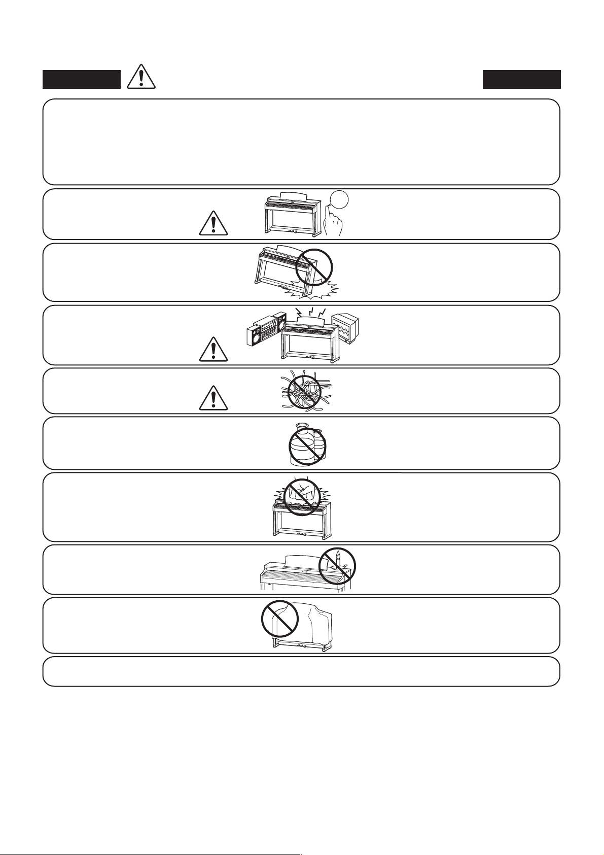
WARNING
The product should be connected to
an AC outlet of the specied voltage.
Do not insert or disconnect the power
cord plug with wet hands.
Take care not to allow any foreign
matter to enter the product.
When using the headphones, do not
listen for long periods of
time at high volume levels.
Do not disassemble, repair or modify
the product.
Indicates a potential hazard that could result in death or
serious injury if the product is handled incorrectly.
120V 240V230V
If you are going to use an AC power cord,
make sure that its has the correct plug shape
and conforms to the specied power voltage.
Failure to do so may result in re.
Doing so may cause electric shock.
Entry of water, needles or hair pins may result
in breakdown or short-circuit.
The product shall not be exposed to dripping or
splashing. No objects lled with liquids, such as
vases, shall be placed on the product.
Doing so may result in hearing problems.
Doing so may result in product breakdown,
electric shock or short-circuit.
When disconnecting the AC power cord's
plug, always hold the plug
and pull it to remove it.
The product is not completely disconnected from the
power supply even when the power switch is turned
o. If the product will not be used for a long time,
unplug the AC power cord from the AC outlet.
Pulling the AC power cord itself may damage
the cord, causing a re, electric shock or
short-circuit.
Failure to do so may cause re in case of
lightning.
Failure to do so may over-heat the product,
resulting in re.
It is good practice to place the instrument near the AC outlet and the power cord plug in a position so that it
can readily be disconnected in an emergency because electricity is always charging while the plug is in the
AC outlet even in a power switch o condition.
Ensure that this product is connected to a socket with a protective earth connection.
GROUNDING INSTRUCTIONS
This product must be grounded. If it should malfunction or breakdown, grounding provides a path of least
resistance for electric current to reduce the risk of electric shock. This product is equipped with a cord having
an equipment-grounding conductor and a grounding plug. The plug must be plugged into an appropriate
outlet that is properly installed and grounded in accordance with all local codes and ordinances.
DANGER - Improper connection of the equipment-grounding conductor can result in a risk of electric shock.
Check with a qualied electrician or serviceman if you are in doubt as to whether the product is properly
grounded. Do not modify the plug provided with the product - if it will not t the outlet, have a proper outlet
installed by a qualied electrician.
Indicates a potential hazard that could result in injury or
CAUTION
Do not use the product in the following areas.
Areas, such as those near windows, where the product is
exposed to direct sunlight
Extremely hot areas, such as near a heater
Extremely cold areas, such as outside
Extremely humid areas
Areas where a large amount of sand or dust is present
Areas where the product is exposed to excessive
vibrations
damage to the product or other property if the product
is handled incorrectly.
Using the product in such areas may result in
product breakdown.
Use the product only in moderate climates (not
in tropical climates).
Before connecting cords, make sure
that the power to this product
and other devices is turned
OFF.
Do not drag the product on the oor.
Take care not to drop the product.
Do not place the product near electrical
appliances such as TVs and radios.
When connecting the AC power cord
and other cords, take care
not to get them tangled.
Do not wipe the product with benzene
or thinner.
Do not stand on the product or exert
excessive force.
OFF
Failure to do so may cause breakdown of this
product and other devices.
Please lift up the product when moving it.
Please note that the product is heavy and must
be carried by more than two persons.
Dropping the product may result in breakdown.
Doing so may cause the product to generate
noise.
If the product generates noise, move the
product suciently away from the electrical
appliance or connect it to another AC outlet.
Failure to do so may damage them, resulting in
re, electric shock or short-circuit.
Doing so may result in discoloration or
deformation of the product.
When cleaning the product, put a soft cloth in
lukewarm water, squeeze it well, then wipe the
product.
Doing so may cause the product to become
deformed or fall over, resulting in breakdown
or injury.
Do not place naked ame, such as lighted
candles on the product.
Ensure that the ventilation is not
impeded by covering the ventilation
openings with items, such as newspaper,
table-cloths, curtains, etc.
The product should be located so that its location or position does not interfere with its proper ventilation. Ensure a
minimum distance of 5cm around the product for sucient ventilation.
Doing so may cause the illumination to fall over,
resulting in re.
Failure to do so may over-heat the product,
resulting in re.
6
7
• The power supply cord or the plug has been damaged.
• Objects have fallen, or liquid has been spilled into the product.
• The product has been exposed to rain.
• The product does not appear to operate normally or exhibits a marked change in performance.
• The product has been dropped, or the enclosure damaged.
&)
Should an abnormality occur in the product, immediately turn the power OFF, disconnect the power cord plug, and then contact
the shop from which the product was purchased.
#-+$
,)&#&!"#*(()+*%+*)"
#%(')&The wires in this mains lead are coloured in accordance with the following code:
• GREEN-AND-YELLOW: EARTH
• BLUE: NEUTRAL
• BROWN: LIVE
As the colours of the wires in the mains lead of this apparatus may not correspond with the coloured markings identifying the
terminals in your plug, proceed as follows.
• The wire which is coloured GREEN-AND-YELLOW must be connected to the terminal in the plug which is marked by the
letter E or by the safety earth symbol or coloured GREEN or GREEN-AND-YELLOW.
• The wire which is coloured BLUE must be connected to the terminal which is marked with the letter N or coloured BLACK.
• The wire which is coloured BROWN must be connected to the terminal which is marked with the letter L or coloured RED.
-/-
If your product is marked with this recycling symbol it means that, at the end of its life, you must dispose of it separately
by taking it to an appropriate collection point. You should not mix it with general household waste. Disposing of this
product correctly will prevent potential negative eects on the environment and human health which could otherwise
arise due to inappropriate waste handling. For further details, please contact your local authority. (European Union only)
)#-).
This instrument complies with the limits for a class B digital apparatus, pursuant to the Radio Interference Regulations, C.R.C., c.1374.
#-/+*
+#'& Changes or modications not expressly approved by the party responsible for compliance could void the user’s
authority to operate the equipment.
&' This equipment has been tested and found to comply with the limits for a Class B digital device, pursuant to Part 15 of the
FCC Rules. These limits are designed to provide reasonable protection against harmful interference in a residential installation.
This equipment generates, uses and can radiate radio frequency energy and, if not installed and used in accordance with the
instructions, may cause harmful interference to radio communications. However, there is no guarantee that interference will not
occur in a particular installation. If this equipment does cause harmful interference to radio or television reception, which can be
determined by turning the equipment o and on, the user is encouraged to try to correct the interference by one or more of the
following measures:
• Reorient or relocate the receiving antenna.
• Increase the separation between the equipment and receiver.
• Connect the equipment into an outlet on a circuit dierent from that to which the receiver is connected.
• Consult the dealer or an experienced radio/TV technician for help.
Declaration of Conformity
Products:
Model Number:
Responsible Party Name:
Address:
Telephone:
This device complies with Part 15 of the FCC Rules. Operation is subject to the following two conditions:
(1) this device may not cause harmful interference, and
(2) this device must accept any interference received, including interference that may cause undesired operation.
Electronic Piano
MP6
Kawai America Corporation
2055 East University Drive, Rancho Dominguez, CA 90220
310-631-1771
This applies only to products distributed by Kawai America Corporation.

Table of Contents
Welcome to the MP6 .....................................................3
Important Safety Instructions .................................4
1. Part Names and Functions..........................10
1.1 FRONT PANEL .................................................................................... 10
1.2 HEADPHONE JACK ..........................................................................12
1.3 REAR PANEL .........................................................................................13
2. Basic Operations............................................. 15
2.1 Getting Ready ....................................................................................15
2.2 Selecting a Sound ......................................................................... 16
2.3 Layer .........................................................................................................17
2.4 Split ...........................................................................................................17
2.5 Piano Only ........................................................................................... 18
2.6 Metronome/Drum Rhythms .................................................. 18
2.7 Transpose ..............................................................................................19
2.8 Using the MP6 as a MIDI controller ....................................19
2.9 Selecting a SETUP .......................................................................... 21
3. SW Button.........................................................22
3.1 Panel Lock ............................................................................................ 22
3.2 Touch Curve ....................................................................................... 22
3.3 Rotary Slow/Fast ............................................................................. 23
3.4 EQ Bypass On/O ........................................................................... 23
3.5 Wheel Lock ........................................................................................ 24
3.6 Foot Switch Lock ............................................................................ 24
3.7 Expression Pedal Lock ................................................................ 25
3.8 Amp Simulato
r On/O (ZONE1 only)...............................25
4. EFX/REVERB Buttons.....................................26
4.1 EFX .............................................................................................................26
4.2 REVERB ...................................................................................................27
5. Control Knobs..................................................28
5.1 EFFECT .................................................................................................... 28
5.2 EQ (EQUALIZER) ............................................................................... 30
5.3 TONE MODIFY .................................................................................. 31
5.4 ASSIGN ................................................................................................... 32
5.4.1 Amp Simulator parameter ............................................. 32
5.4.2 MIDI CC# (Control Change) ........................................... 32
6. MENU Buttons.................................................34
6.1 Editing Procedure and Parameters ................................... 35
6.2 Edit Parameters ............................................................................... 35
6.2.1 Zone Mode .............................................................................. 35
6.2.2 Sound (Int only) .................................................................... 35
6.2.3 Damper Resonance (Int Piano only) ........................36
6.2.4 String Resonance (Int Piano only) ............................. 36
6.2.5 Key -o Eect (Int Piano onl y) ......................................36
6.2.6 Voicing (Int Piano only) ....................................................36
6.2.7 KeyO Noise (Int EP only) ............................................... 37
6.2.8 KeyO Delay (Int EP only)............................................... 37
6.2.9ToneWheelRegistration
(ZONE1 Int Tone Wheel only) .................................... 37
6.2.10 Tone Wheel Percussion
(ZONE1 Int Tone Wheel only) ................................... 37
6.2.11 Tone Wheel Percussion Level
(ZONE1 Int Tone Wheel only) ................................... 37
6.2.12 Tone Wheel Percussion Decay
(ZONE1 Int Tone Wheel only) ...................................38
6.2.13 Tone Wheel Percussion Harmonics
(ZONE1 Int Tone Wheel only) ...................................38
6.2.14 Tone Wheel Key Click Level
(ZONE1 Int Tone Wheel only) ...................................38
6.2.15 EFX Type .................................................................................. 38
6.2.16 EFX parameter ..................................................................... 38
6.2.17 Amp Simulator On/O (ZONE1 Int only) ............ 38
6.2.18 Amp Simulator Drive (ZONE1 Int only) ................ 39
6.2.19 Amp Simulator Level (ZONE1 Int onl y) ................ 39
6.2.20 Amp Simulator EQ Hi/Lo (ZONE1 Int only) ....... 39
6.2.21 Trs Ch (Ex t only) ................................................................. 39
6.2.22 Trs PRG# (Ex t only) ........................................................... 39
6.2.23 Bank MSB/L SB (E xt only) .............................................. 40
6.2.24 Keyboard On/O (Ex t only) ........................................40
6.2.25 Velocity Dynamics ........................................................... 40
6.2.26 Solo ...........................................................................................40
6.2.27 Solo Mode ............................................................................. 41
6.2.28 Damp er ................................................................................... 41
6.2.29 Foot Switch .......................................................................... 41
6.2.30 Expression Pedal ............................................................... 41
6.2.31 Modulation ........................................................................... 41
6.2.32 Bender ..................................................................................... 42
6.2.33 Bender Range ..................................................................... 42
6.2.34 Key Range Hi/Lo ................................................................ 42
6.2.35 Velocit y Switch ................................................................... 43
6.2.36 Velocity Switch Value ..................................................... 43
6.2.37 Zone Transpose ................................................................. 44
6.2.38 Volume ....................................................................................44
6.2.39 Pan ............................................................................................. 44
6.2.40 Fine Tune ...............................................................................4 4
6.3 Common Parameters ..................................................................45
6.3.1 Stretch Tuning........................................................................ 45
6.3.2 Temp erament ........................................................................ 45
6.3.3 Key of Temperament.........................................................46
6.3.4 User Tuning ............................................................................. 46
6.3.5 Foot SW CC# (Control Change) ................................... 46
6.3.6 E XP CC# (Control Change) ............................................. 46
6.3.7 Modulation Wheel CC# (Control Change) ........... 47
6.3.8 Left Pedal Mode ................................................................... 47
6.3.9 Master Volume ...................................................................... 47
7. Song Recorder (Internal Memory)........................48
7.1 Recording a song ............................................................................48
7.1.1 Entering song recorder mode ...................................... 48
7.1. 2 Starting the song recorder ............................................. 48
7.1.3 Stopping the song recorder .......................................... 48
7.2 Playing back a song ...................................................................... 49
7.2.1 Entering song p lay mode ............................................... 49
7.2.2 Star ting the song playback ........................................... 49
7.2.3 A- B Repeat ............................................................................... 49
7.2.4 Exiting song play mode ................................................... 49
7.3 Erasing a song ................................................................................... 50
7.3.1 Entering erase mode .......................................................... 50
7.3.2 Erasing a song ........................................................................50
8

9
8. Audio Recorder/SMF Player (USB Memory) ....51
8.1 Recording an audio le .............................................................. 51
8.1.1 Entering audio recorder mode .................................... 51
8.1.2 Starting the audio recorder ........................................... 51
8.1.3 Stopping the audio recorder ........................................ 51
8.2 Playing an audio le..................................................................... 52
8.2.1 Entering audio playback mode .................................. 52
8.2.2 Selecting an audio le ..................................................... 52
8.2.3 Starting audio le playback .......................................... 52
8.2.4 Exiting audio recorder mode ....................................... 52
8.3 Playing a standard MIDI le ................................................... 52
8.3.1 Entering SMF playback mode ...................................... 53
8.3.2 Selecting an SMF le ......................................................... 53
8.3.3 Starting SMF playback......................................................53
8.3.4 Adjusting SMF volume, Transposing the SMF,
Minus One ............................................................................. 54
8.3.5 Exiting audio recorder mode .......................................54
9. STORE Button ..................................................55
9.1 Storing the settings as a SOUND ......................................... 55
9.2 Storing the settings as a SETUP ........................................... 56
9.3 Storing the POWER ON setting ............................................ 57
10. SYSTEM Button .............................................58
10.1 System Menu .................................................................................. 58
10.2 System Parameters ....................................................................58
10.2.1 System Channel .............................................................. 58
10.2.2 Touch .....................................................................................59
10.2.3 System Tuning .................................................................60
10.2.4 Volume Slider Ac tion ................................................... 60
10.2.5 Reverb O set .................................................................... 6 0
10.2.6 EQ O set O n/O ............................................................ 60
10.2.7 EQ Oset ............................................................................. 60
10.2.8 Lo cal Control .....................................................................61
10.2.9 Program Change Mode ..............................................61
10.2.10 MIDI Receive Mode .....................................................61
10.2.11 MIDI Receive Channel ............................................... 62
10.2.12 MIDI Transmit SETUP Mode...................................62
10.2.13 MIDI Transmit Program Change ......................... 62
10.2.14 M IDI Transmit Bank ..................................................... 62
10.2.15 MIDI Transmit Volume .............................................. 63
10.2.16 M IDI Transmit Control Change ............................ 63
10.2.17 MIDI Transmit Recorder ...........................................63
10.2.18 MMC On/O ...................................................................6 4
10.2.19 MMC Assign ....................................................................64
10.2.20 MMC Device ID .............................................................64
10.2.21 LCD Contrast .................................................................. 64
10.2.22 LED Brightness .............................................................. 65
10.2.23 O ut Mode ........................................................................ 65
10.2.24 Foot Switch Mode ..................................................... 65
10.2.25 W heel Mode .................................................................. 66
10.3 System Reset...................................................................................67
10.3.1 Reset O ne SOUND/SETUP ........................................ 67
10.3.2 Reset All ............................................................................... 67
11. USB Button......................................................68
11.1 Load ....................................................................................................... 68
11.1.1 Selec ting Load .................................................................. 68
11.1.2a Loading SETUP data ................................................... 69
11.1.2b Loading SOUND data ................................................ 69
11.1.2c Loading SYS TEM data ................................................ 70
11.1.2d Loading SMF data ........................................................ 70
11. 2 S av e ........................................................................................................ 71
11.2.1 Selecting Save .................................................................. 71
11.2.2a Saving SETUP data ...................................................... 71
11.2.2b Saving SOUND data ................................................... 72
11.2.2c S aving SYST EM data ...................................................72
11.2.2d S aving SMF data ........................................................... 73
11. 3 R en am e ............................................................................................... 73
11.3.1 Selecting Rename .......................................................... 73
11.3.2a Renaming SETUP data ...............................................74
11.3.2b Renaming SOUND data ............................................74
11.3.2c Renaming SYSTEM data ........................................... 75
11.3.2d Renaming SONG data .............................................. 75
11. 4 D el e te ................................................................................................... 76
11.4.1 Selecting Delete .............................................................. 76
11.4.2a Deleting SETUP data .................................................. 76
11.4.2b D eleting SOUND data .............................................. 76
11.4.2c Deleting SYSTEM data .............................................. 77
11.4.2d Deleting SONG data .................................................. 77
11. 5 F or m at.................................................................................................. 77
11.5.1 Selecting Format .............................................................77
11.5.2 Starting the Format ....................................................... 77
12. Reference Information ...............................78
12.1 M IDI I N ................................................................................................. 78
12.2 SETUP Program Number Table ......................................... 78
12.3 SOUND Program Number List ........................................... 79
12.4 Drum Rhythm List ....................................................................... 85
12.5 USB MIDI (USB to Host) ............................................................86
12.6 Specications .................................................................................87
13. MIDI Implementation .................................88
13.1 Recognized Data .......................................................................... 89
13.1.1 Channel Voice m ess age ................................................. 89
13.1.2 Channel Mode Message ............................................... 92
13.1.3 System Real time Message .......................................... 92
13.2 Transmitted Data ......................................................................... 92
13.2.1 Channel Voice Message ................................................ 92
13.2.2 Channel Mode Message .............................................. 95
13.2.3 System R eal time Message ......................................... 95
13.3 Exclusive Data ................................................................................ 95
13.3.1 Universal Real time Exclusive Mess age ...............95
13.4 Control Change Number (CC#) Table ............................96
MIDI Implementation Chart ........................................................... 97
1. Part Names and Functions
1.1 FRONT PANEL
FADER SECTION
1. VOLUME Fader
The VOLUME fader controls the master volume level of the MP6.
2. ZONE SELECT buttons
The ZONE SELECT buttons are used to select one of the four zones for editing. Only one
zone can be selected at a time. The front panel setting represents the current zone status.
3. ON/OFF buttons
The ON/OFF buttons are used to turn zones ON/OFF. When the button is lit, the zone is
active. Normally the button color is red, but when a zone is not using the full keyboard
range the color will be green to indicate it.
4. FADERS (zone volume level control)
Each fader controls the volume level of a designated zone. When multiple zones are
active, these faders can be used as an audio mixer.
b
b
1. Part Names and Functions
a
a
d
d
c
c
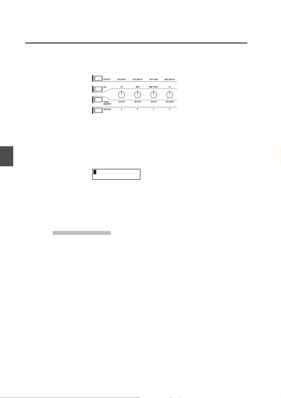
CONTROL KNOBS SECTION
The four CONTROL KNOBS are multi-function real time controllers. The dierent functions
can be selected using the four buttons to the left side of the CONTROL KNOBS. When a
function is active, its button is lit. Touching any of these knobs will instantly change the
display to the current knob function and value.
5. EFFECT button
When this button is lit, the CONTROL KNOBS will adjust the REVERB time, REVERB depth,
EFX rate and EFX depth.
6. EQ button
When this button is lit, the CONTROL KNOBS will adjust the 3-band graphic equalizer.
7. TONE MODIFY button
When this button is lit, the CONTROL KNOBS will adjust the CUTOFF, ATTACK, DECAY and
RELEASE Levels for the selected zone.
8.ASSIGN button
When the Amp Simulator is ON : The CONTROL KNOBS adjust the Amp Simulator settings.
e
e
f
f
g
g
h
h
k
k
l
l
m
m
n
n
10
When the Amp Simulator is OFF : The CONTROL KNOBS adjust MIDI control changes that
are sent from the MP6 to an external MIDI device specied by the selected zone. Some
control changes can also be used with the internal sounds.
WHEEL CONTROLLERS
9. PITCH BEND
This control wheel smoothly bends the pitch Up or Down from its current value.
10. MODULATION
This control wheel controls the modulation (vibrato) depth. Moving the wheel forward
increases the vibrato depth.
ijij
11
1. Part Names and Functions
EFFECT BUTTONS
11. SW button
This button turns the assigned function ON or OFF. Many dierent functions can be
assigned to this switch for your convenience.
When in edit mode, pressing the SW button will exit from edit mode.
12. EFX button
This button turns the EFX ON or OFF for the selected zone.
13. REVERB button
This button turns the REVERB ON or OFF for the selected zone.
To change the function or type assigned to the above buttons, press and hold the
desired button to display the currently selected function or type, then use the VALUE
buttons to change it.
MENU BUTTONS
14. MENU buttons
The MENU buttons are used to enter the edit mode and scroll through all the various
parameters of the MP6. To change a parameter value, use the VALUE buttons.
DISPLAY
15. DISPLAY
s
s
t
t
poq
poq
r
r
VALUE BUTTONS
16. VALUE buttons
The VALUE buttons are used to change the value of the current parameter as indicated
on the DISPLAY.
SOUND SELECTION & SETUP SELECTION
17. SOUND button
The SOUND button switches the MP6 to the SOUND mode. The SOUND SELECT buttons
will now select any of the 256 internal sounds.
18. SETUP button
The SETUP button switches the MP6 to the SETUP mode. The SOUND SELECT buttons
will now select any of the 256 SETUPs.
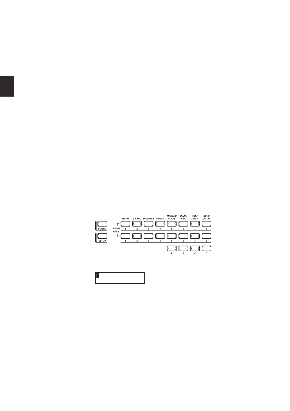
19. SOUND SELECT buttons
The SOUND SELECT buttons are organized in two rows of eight buttons and one row of
four ones. In SOUND mode the upper row of buttons is used to select a sound category
and the second & third rows of buttons is used to select the dierent internal sounds within
each category. In SETUP mode the upper row of buttons is used to select a bank and the
second & third rows of buttons is used to select the dierent SETUPs within each bank.
u
u
v
v
w
w
x
x
y
y
z
z
RECORDER SECTION
20. RECORDER CONTROL buttons
The RECORDER CONTROL buttons are used for Rec/Play functionality in Recorder Mode.
When Recorder Mode is not in use, the RECORDER CONTROL buttons can be used to
send MMC messages to external MIDI devices.
21. RECORDER button
The RECORDER button is used to access the Internal Song and USB Audio recorder
functions.
OTHERS
22. METRONOME button
The METRONOME button is used to start or stop the metronome.
23. TRANSPOSE button
The TRANSPOSE button is used to turn the TRANSPOSE function ON/OFF.
24. STORE button
The STORE button is used to store the settings of the MP6.
25. SYSTEM button
The SYSTEM button is used to set the system parameters of the MP6.
26. USB button
The USB button is used to access the MP6’s USB functions: Load, Save, Rename, Delete,
and Format.
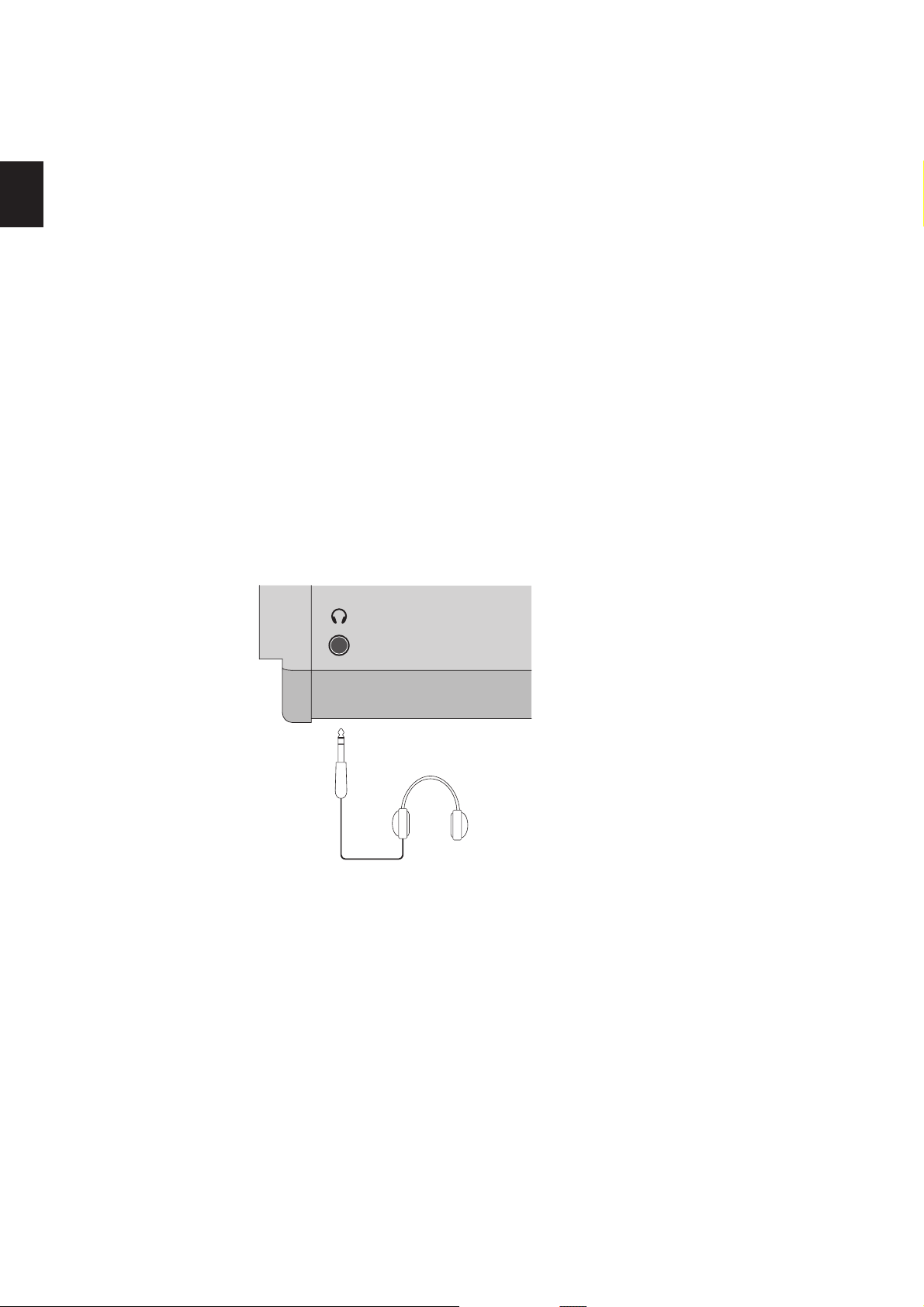
1. Part Names and Functions
1.2 HEADPHONE JACK
The headphone jack is located in front at the left end of the key slip.
Use a headphone with a standard stereo 1/4 inch phone jack.
12

13
1. Part Names and Functions
1.3 REAR PANEL
1. POWER SWITCH
2. POWER RECEPTACLE
3. MIDI JACKS
4. USBtoHostPORTto Host PORTto Host PORT
5. FOOT CONTROLLERS
6. FOOT SWITCH
Turns the MP6 ON or OFF.
Connect the power cable, which is included in the MP6 package, to this receptacle.
These jacks are used to connect the MP6 with external MIDI devices such as a MIDI sound
module or a MIDI sequencer.
This jack is used to connect the MP6 with a personal computer. See page 86 for details.
EXP JACK
An expression pedal can be connected to this jack.
The expression pedal can be assigned to dierent MIDI control numbers or functions in
the Menu.
DAMPER JACK
This jack is used to connect the Foot Pedal included with the MP6 (KAWAI F-10H).
A momentary footswitch can be connected to this jack (EX: KAWAI F-1 or F-20). The
FootSwitch can be assigned to dierent MIDI control numbers or functions in the Menu.
When using the KAWAI F-20. The right pedal works as a Foot Switch, and the left pedal
works as a Soft pedal. When the Rotary EFX is in use, the Soft pedal changes between
Fast & Slow Rotor speeds.
7. OUTPUTS
R, L/MONO OUTPUTS
The R, L/MONO outputs are used to connect the MP6 to a musical instrument amplier
using standard 1/4 inch phone jacks. The R, L/MONO outputs can also be used to conne ct
the MP6 to a PA system or recording console.
8. USB TO DEVICE PORT
This port allows a USB memory device to be connected to the MP6.
1. Part Names and Functions
Expression
Pedal
Keyboard amplier
PA equipments
(Ex. Mixer, Multi-track recorder)
F-10H
a
b
c
de hf
Terminal B
Terminal A
MIDI devices
(Ex. External Sound module, External Sequencer,
Keyboards, Personal Computers)
g
Foot Switch (Optional)
F-20 F-1
14

15
2. Basic Operations
2.1 Getting Ready
Since the MP6 has no built-in speakers, you will need to connect a mixer,
keyboard amplier or headphones in order to listen.
Turn the MP6 on, using the POWER SWITCH on the rear panel.
It is recommended to turn the MP6 on before turning on any ampliers in order
to avoid switching noise.
What you need to know before starting:
Please read this part for a better understanding of the MP6 structure.
The MP6’s SOUND and SETUP modes are largely the same. The main dierence
between the two is that SETUP is used to recall stored SETUPs. Edits and changes
can be made freely in either mode, using the 4 faders, 4 knobs and MENU
functions, however edits made in SOUND mode will be lost when the power is
turned OFF and must therefore be stored in SETUP mode.
In order to start from scratch, use the SOUND mode and press PIANO ONLY
rst.
In order to modify a SETUP, select the desired SETUP, perform any edits, and
store the changes as a SETUP.
2. Basic Operations
If selected sounds do not sound correct, it is possible that parameters (knobs
etc.) were edited. To restore sounds to their default setting, use the PIANO ONLY
function, then re-select the desired sound.
2. Basic Operations
2.2 Selecting a Sound
The MP6 always starts up in SOUND mode when the power is turned ON. The
SOUND button will be lit to indicate SOUND mode is active.
Operation 1
Select the sound category by pressing a sound select button in the top row.
There are 3 rows of sound select buttons, the top row is for selecting a sound
category and the second and third rows are for selecting a variation.
For example, to select "60’s EP2", rst press the E.PIANO in the top row and the
rst sound in the E.PIANO category "Classic EP" is recalled. (If any other variation
was selected before, the last selected sound is recalled as long as the power is
on.)
Operation 2
Select the rst variation by pressing a sound select button in the second row.
Press one of the 1-8 buttons in the second row. If you press 3, the variation 3
"60’s EP" is recalled. (If any other variation was selected before, the last selected
sound is recalled as long as the power is on.)
Operation 3
Select the second variation by pressing a sound select button in the third row.
Press one of the A-D buttons in the third row. If you press B, a variation sound
"60’s EP2" is recalled.
Select the variations with the sound select buttons in the second and third
rows.
16
The display shows the currently selected sound name.
1 Concert Grand
Note:
Internal sounds or Setups can be also selected using the VALUE buttons.
You should also listen to the preprogrammed Setups.
Setups are organized in 8 Banks with 32 Numbers each (total 256 Setups).
Press the SETUP button to change to SETUP mode and select a Setup by pressing
one of the Bank buttons in the upper row followed by a Number button in the
second and third row.
The display shows the currently selected Setup name.
In Sound mode, the “1” in the display indicates that the zone 1 is currently
selected.
17
2. Basic Operations
2.3 Layer
2.4 Split
Let’s try layering another sound. Turn the zone 2 on by pressing the ZONE ON/
OFF button for zone 2. The ZONE SELECT button for zone 2 is automatically
selected and the display shows the sound name for zone 2.
Select the sound for zone 2 with the SOUND SELECT buttons as shown in the
previous section.
2 String Pad
Adjust the volume balance of zone 1 and 2 with the faders for each zone.
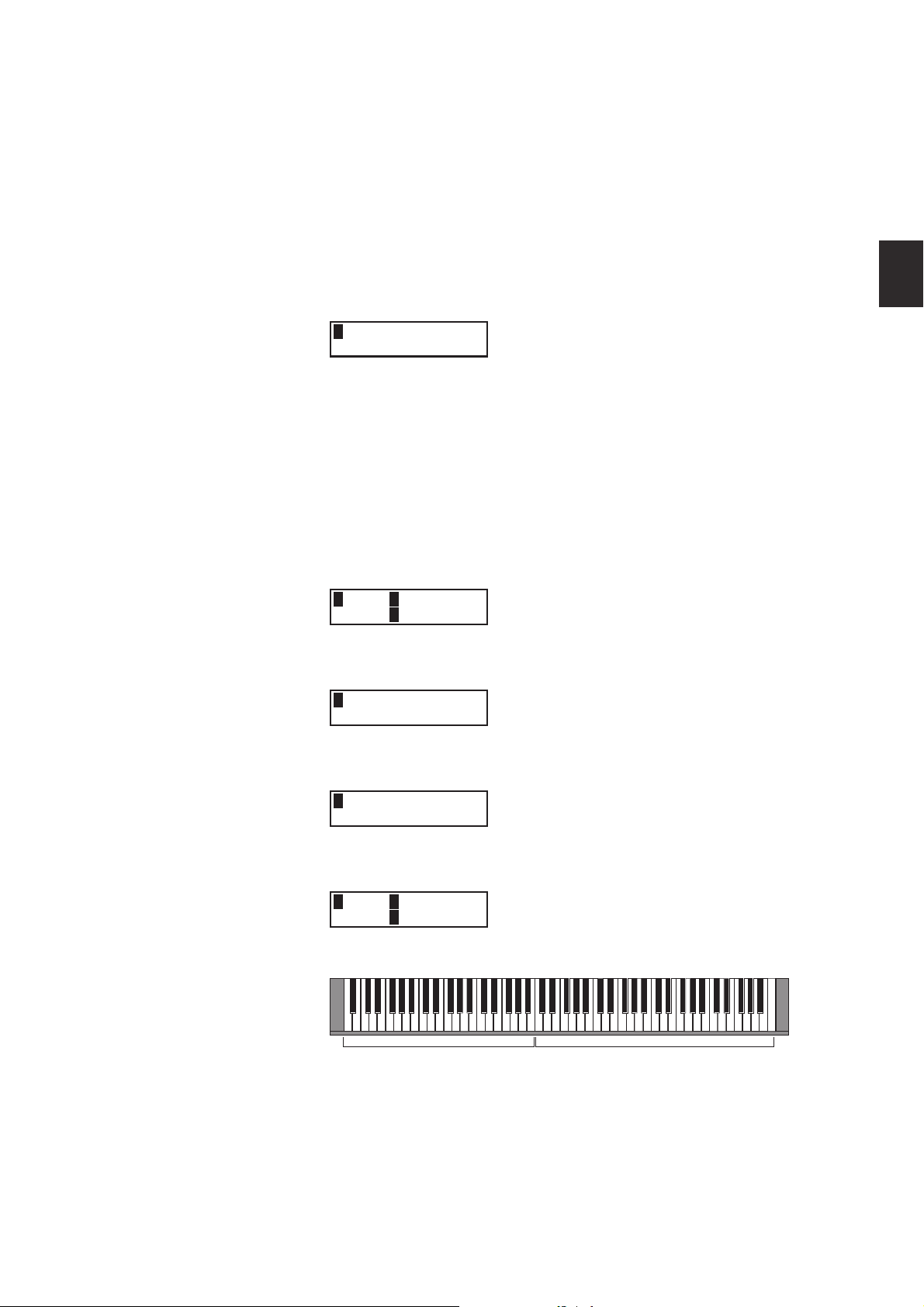
Now let’s split the keyboard and play dierent sounds in upper and lower
sections.
Press and hold the ZONE SELECT button for zone 1. The display shows the key
range for zone 1 as follows.
1Key IA-1 >C7
RangeEA-1 >C7
While still holding down the ZONE SELECT button for zone 1, press the lowest
note on the keyboard. The display changes as follows.
1KeyRange(Both)
= A-1 > ----
While still holding down the ZONE SELECT button for zone 1, select the highest
note for zone 1, for example, B2 by pressing B2 key on the keyboard.
1KeyRange(Both)
= A-1 > B2
Repeat the same procedure for zone 2 while holding down the ZONE SELECT
button for zone 2 and set the key range from C3 to C7.
2Key IC3>C7
RangeEC3>Cc7
Now the keyboard is split as follows.
ZONE1 ZONE 2
Note:
In this method, the key ranges for internal and external zones always change
together. If you want individual settings, use the Key Range Hi/Lo parameter in
MENU (see page 42).
q
q
B2
C3
2. Basic Operations
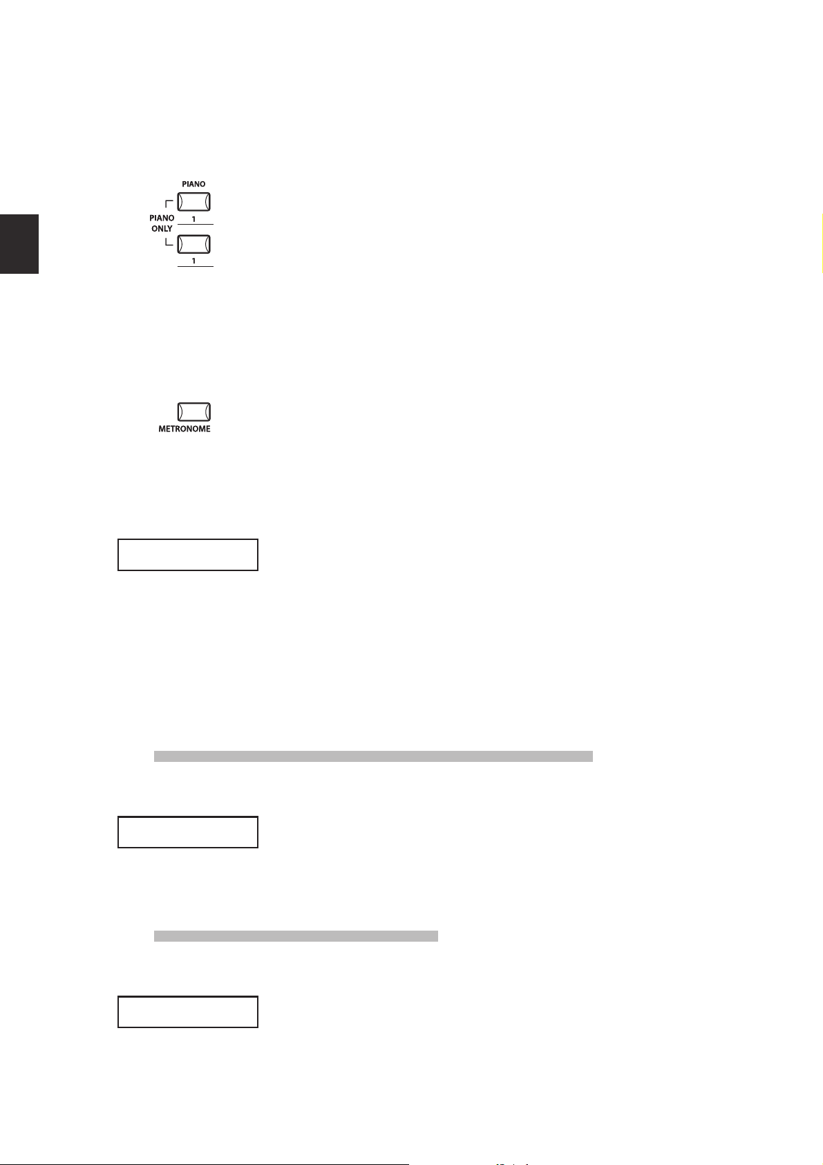
2.5 Piano Only
The Piano Only function lets you quickly return the MP6 sounds to the default
settings.
Press the PIANO button and the SOUND SELECT button 1 simultaneously. All the
current settings (except for SYSTEM settings) will go back to original and only
Concert Grand sound can be played on the whole keyboard.
NOTE: You may use this function also as a kind of Panic or Reset button. Also it is a
good starting point to create Setups from scratch.
2.6 Metronome/Drum Rhythms
The Metronome function provides a steady beat to aid practicing the piano
at a consistent tempo. In addition to regular metronome beats, the MP6 also
features a variety of drum rhythms to accompany most musical genres.
Press the METRONOME button to start the metronome.
A beat will start to count and the LED indicators for the STORE and SYSTEM
buttons will ash in time with the sound.
1/4
1/4
1/4
1/4
The time signature and tempo will also be shown in the LCD display.
œ=120
œ=120
Press the VALUE buttons to increase or decrease the tempo.
* The metronome tempo can be adjusted within the range of 30-300 bpm (60-
600 bpm for eighth note rhythms).
* The metronome conguration can be stored to a SETUP/POWER ON memory.
Press the MENU buttons to show the metronome time signature/pattern or
metronome volume screens in the LCD display.
Changing the Metronome time signature/drum rhythm
When ‘Pattern’ is shown in the LCD display:
Pattern
Pattern
Press the VALUE buttons to selected the desired time signature/drum rhythm.
* There are ten dierent types of time signature available:
1/4, 2/4, 3/4, 4/4, 5/4, 3/8, 6/8, 7/8, 9/8, and 12/8.
* Please refer to page 82 of this owner’s manual for a full list of available drum rhythms.
Changing the Metronome volume
18
1/4
1/4
Metro Volume =10
Metro Volume =10
When ‘Metro Volume’ is shown in the LCD display:
Press the VALUE buttons to increase or decrease the metronome volume.
* The metronome volume can be adjusted within the range of 0-10.
Press the EXIT button to return to the previous screen.
19
2. Basic Operations
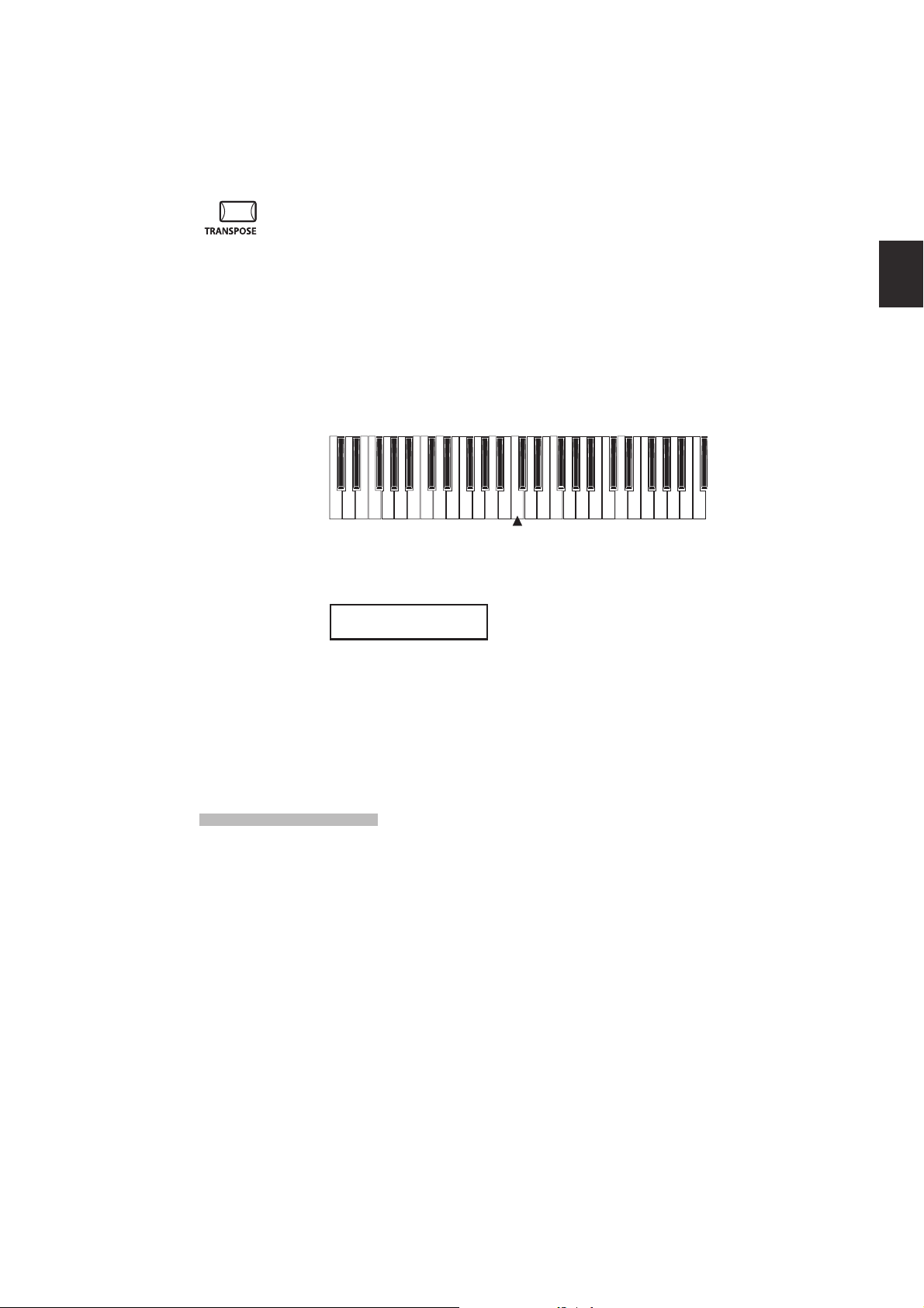
2.7 Transpose
When the Transpose function is “ON” the MP6’s key can be raised or lowered
in half steps. The available range of transposition is 24 semitones, either up or
down.
While holding down the TRANSPOSE button, press any key on the MP6 keyboard
to select a new transposed key. Pressing the F key above middle C for example
will transpose the MP6 UP to the key of F (+5 half steps).
The transpose amount can also be set using the VALUE buttons.
While holding the TRANSPOSE button down, press the VALUE buttons to change
the transpose amount.
-24 -12 0 +12 +24
The display shows the current TRANSPOSE amount when the TRANSPOSE
button is held down. A value of “0” indicates no transposition.
MASTER TRANS
+10
2.8 Using the MP6 as a MIDI controller
The MP6 can control external devices via MIDI.
MIDI Connection
Connect the MIDI OUT on the MP6 to the MIDI IN on an external MIDI device
with a MIDI cable.
C3

2. Basic Operations
Selecting the MIDI Channel
The MIDI Transmit Channel of the MP6 must be matched with the Receive
Channel of any MIDI devices connected to the MP6.
Select zone 3 by pressing the ZONE SELECT button 3. (Zone 3 is set to external
as default setting.)
Press the MENU c button until “TrsChannel” (Transmit Channel) appears on the
display.
3Externel
STrsChannel = 1
Use the VALUE buttons to choose a MIDI Transmit Channel from 1 to 16.
To exit from MENU, press the EXIT(SW) button.
Any notes played on the keyboard or any movements of the Knobs, sliders, etc.
will be transmitted to any external MIDI devices connected to the MIDI out of
the MP6 on the selected MIDI channel.
Sending Program Change Number
The MP6 can send MIDI program change numbers from 1 to 256 and Bank
number LSB from 0 to 1 in SOUND mode. Simply press the SOUND SELECT
buttons and the corresponding program number will be transmitted. See the
program number table below.
UPPER SECOND THIRD PROG#:MSB-LSB
1 1 A 001:000-000
1 1 B 002:000-000
1 1 C 003:000-000
1 1 D 004:000-000
1 2 A~D 005:000-000 ~ 008:000-000
1 3 A~D 009:000-000 ~ 012:000-000
1 4 A~D 013:000-000 ~ 016:000-000
1 5 A~D 017:000-000 ~ 020:000-000
1 6 A~D 021:000-000 ~ 024:000-000
1 7 A~D 025:000-000 ~ 028:000-000
1 8 A~D 029:000-000 ~ 032:000-000
2 1~8 A~D 033:000-000 ~ 064:000-000
3 1~8 A~D 065:000-000 ~ 096:000-000
4 1~8 A~D 097:000-000 ~ 128:000-000
5 1~8 A~D 001:000-001 ~ 032:000-001
6 1~8 A~D 033:000-001 ~ 064:000-001
7 1~8 A~D 065:000-001 ~ 096:000-001
8 1~8 A~D 097:000-001 ~ 128:000-001
20

21
2. Basic Operations
The transmitted program number is shown in the display.
3
You can also send program change numbers by using VALUE buttons.
Note:
Full program change numbers including bank numbers can be transmitted by
setting them in MENU and saving it as a SETUP. See page 39/40 for details.
2.9 Selecting a SETUP
The MP6 oers 256 preset combinations of the panel settings called SETUPs.
To select a SETUP, press the SETUP button. Now the SOUND SELECT buttons are
used to select a SETUP. Use a combination of the numbers in the upper, second
and third rows to select a desired SETUP. The display will show the selected
SETUP name.
GrandPno1+Str1
To check the sound (internal) or program number (external) assigned to each
zone, press the ZONE SELECT button. The display briey shows the assigned
sound name or program number, and then automatically returns to the SETUP
name in a few seconds.
If you hold a ZONE SELECT button for 2 seconds the display will show you the
key range information for that zone. You can also set the key range using the
same procedure that is used in Sound mode.
001:000-000 01
3. SW Button
3. SW Button
The SW button is a programmable realtime switch which can be assigned to one
of 8 dierent functions.
Press and hold the SW button. The display shows the currently assigned function.
Press the SW button again to exit without changing the function.
SW TYPE/COMMON
1:Panel Lock
Use the VALUE buttons to change the function. The display will automatically
return to SOUND or SETUP mode after you change the function.
This function can be stored using the STORE button. (see page 55)
When the MENU function is displayed, the SW button works as an EXIT button.
3.1 Panel Lock
You can lock the panel operation to avoid unnecessary changes to the settings
by accident.
When the SW button is lit Panel Lock is ON.
Panel Lock On: All the operations except for keyboard, wheels, pedals and SW
button are locked. The display shows as follows while the panel is locked.
3.2 Touch Curve
Panel Lock
>Press[SW]button
Panel Lock O: Panel Lock is canceled.
You can temporary turn on/o the Touch Curve for example to play organ
sounds correctly.
Touch Curve On: The display briey shows the selected Touch Curve in the
SYSTEM and the Touch Curve becomes active. If the selected Touch Curve in the
SYSTEM is O, the Normal Touch Curve becomes active.
Touch Curve O: The display briey shows as follows and the Touch Curve
becomes O.
Touch Curve
Off
22

23
3. SW Button
3.3 Rotary Slow/Fast
You can switch the speed of roter between slow and fast when the Rotary eect
is in use.
When the SW button is lit: The display briey shows as follows and the rotary
speed changes to fast.
When the SW button is OFF: The display briey shows as follows and the rotary
speed changes to slow.
Note:
When the Rotary eect is not in use, the display briey shows as follows.
3.4 EQ Bypass On/O
You can temporarily bypass the EQ by turning the SW button on.
When the SW button is lit the EQ Bypass is on.
EQ Bypass On: The display briey shows as follows and the sound bypasses the
EQ.
Rotary Speed
Fast
Rotary Speed
Slow
Rotary is
not selected.
EQ Bypass
On
EQ Bypass O: The display briey shows as follows and the EQ comes back to
active.
EQ Bypass
Off
Note:
When the EQ Bypass is turned on and the EQ control knobs are used, the display
briey shows as follows.
EQ Bypass
>Press[SW]button

3.5 Wheel Lock
You can lock the bender wheel and modulation wheel to avoid unnecessary
movement by accident.
When the SW button is lit the Wheel Lock is on.
Wheel Lock On: The display briey shows as follows and the wheels are locked.
Wheel Lock
On
Wheel Lock O: The display briey shows as follows and the wheels are
unlocked.
Wheel Lock
Off
3. SW Button
Note:
When the Wheel Lock is turned on and the wheels are used, the display briey
shows as follows.
Wheel Lock
>Press[SW]button
3.6 Foot Switch Lock
You can lock the assignable foot switch to avoid unnecessary movement by
accident.
First, connect a foot switch to the FSW jack on the rear panel of the MP6.
When the SW button is lit the Foot Switch Lock is on.
Foot Switch Lock On: The display briey shows as follows and the assignable
foot switch is locked.
FSW Lock
On
Foot Switch Lock O: The display briey shows as follows and the assignable
foot switch is unlocked.
FSW Lock
Off
24
Note:
When the FSW Lock is turned on and the foot switch is used, the display briey
shows as follows.
FSW Lock
>Press[SW]button

25
3. SW Button
3.7 Expression Pedal Lock
You can lock the expression pedal to avoid unnecessary movement by
accident.
First, connect an expression pedal to the EXP jack on the rear panel of the MP6.
When the SW button is lit the Expression Pedal Lock is on.
Expression Pedal Lock On: The display briey shows as follows and the expression
pedal is locked.
EXP Lock
Expression Pedal Lock O: Th e display briey shows as follows and the expression
pedal is unlocked.
EXP Lock
On
Off
Note:
When the EXP Lock is turned on and the expression pedal is used, the display
briey shows as follows.
EXP Lock
>Press[SW]button
3.8 Amp Simulator On/O (ZONE1 only)
You can enable an Amp Simulator eect by turning the SW button on.
When the SW button is lit the Amp Simulator is on.
Amp Simulator On: The display briey shows as follows and the Amp Simulator
turns on.
Amp Simulator
On
Amp Simulator O: The display briey shows as follows and the Amp Simulator
turns o.
Amp Simulator
Off
Note:
The Amp Simulator will be eective for ZONE 1 only.
* Please refer to page 38 of this owner’s manual for further details regarding the
Amp Simulator.
4. EFX / REVERB Buttons
The internal sounds of the MP6 can be enhanced using the built in REVERB and
EFX generators.
There are 7 REVERB types and 23 dierent EFX types to choose from. MP6
contains 4 variations of EFX type per INT section, and dierent EFX can be added
to the sound of each ZONE.
4.1 EFX
The MP6 contains 23 high quality EFX types, designed to complement the
internal sounds. Each internal sound has a preset eect assigned as the default.
The EFX button turns the EFX generator ON or OFF for the selected sound.
To turn the EFX “ON” for the current sound, press the EFX button and the button
will light up. EFX will be added to the current sound.
To turn the EFX “OFF” again, press the EFX button again (the light on the button
will be turned o).
4. EFX/REVERB Buttons
EFX type
Press and hold the EFX button for a few seconds. The display shows EFX type
added to the current selected ZONE.
1 EFX TYPE
18: Rotary 1
Use the VALUE buttons to change the eect type. Each EFX type has a default
value for RATE and DEPTH, so when changing the EFX type, the values are
changed automatically. You can edit these values with the EFX RATE and EFX
DEPTH knobs in the rst row of the CONTROL KNOBS section on the panel.
To select another ZONE, press its ZONE SELECT button.
Chorus Chorus is a slight detuning of the sound, which adds depth and
richness to the sound.
Flanger Flanger introduces a shifting comb-lter, which adds motion and a
“hollow” tone to the sound.
Celeste Celeste is a three phase chorus, with each of the three chorus units
at dierent phase.
Ensemble Ensemble is a three phase chorus, with each of the three chorus
units at a dierent phase and frequency. This gives a slightly richer
sound than the Celeste eect, above.
26
Delay 1/2/3/4 Delay adds echoes to the sound.
AutoPan 1/2/3 AutoPan alternates the sound left and right across the stereo eld
at a variable rate. AutoPan 3 includes an overdrive eect.
Tremolo 1/2/3/4 Tremolo changes the volume of the sound, making it louder and
softer at a variable rate. Tremolo 3 includes an overdrive eect.
Phaser 1/2 Phaser creates a cyclic phase change, adding motion to the sound.
27
4. EFX/REVERB Buttons
4.2 REVERB
Rotary 1/2 The Rotary eect simulates the sound of the rotary speaker cabinet
commonly used with electronic organs. Rotary 2 includes an
overdrive eect.
Auto Wah Auto Wah creates an automatic lter sweep at the attack of each note.
Pedal Wah Pedal Wah creates a lter sweep with the expression pedal
connected to the MP6.
Enhancer Enhancer produces a crisper tone, so the sound is more easily
discernible.
Overdrive Overdrive eect adds tube-amp style distortion.
Note: You can select dierent EFX types for each zone.
The MP6 contains 7 high quality REVERB types, designed to complement the
internal sounds. Each internal sound has a preset REVERB type assigned as
the default. The REVERB button turns the REVERB generator ON or OFF for the
selected sound.
To turn the REVERB “ON” for the current sound, press the REVERB button and the
button will light up. REVERB will be added to the current sound.
REVERB type
To turn the REVERB “OFF” again, press the REVERB button again (The light on
the button will be turned o).
Press and hold the REVERB button until the display shows REVERB type.
REVERB TYPE
1 :Hall 1
Use the VALUE buttons to change the REVERB type. Each REVERB type has a
default value for TIME, so when changing the REVERB type, the value is changed
automatically.
Hall 1 Simulates the reverb in a standard hall
Hall 2 Simulates the reverb in a small hall
Stage 1 Simulates the reverb on a standard stage
Stage 2 Simulates the reverb on a small stage
Room 1 Simulates the reverb in a standard room
Room 2 Simulates the reverb in a small room
Plate Simulates the reverb of a metallic plate
Note: REVERB type is common to all internal zones. You cannot select a dierent
type for each zone. But you can individually turn on/o or set dierent depths for
each zone.
5. Control Knobs
Select the function with the buttons on the left and use the knobs to change
the values. You can also move the cursor with the MENU buttons and change
the value with the VALUE buttons while the display is showing Control Knobs
function.
5.1 EFFECT
Make sure that the EFFECT button in the CONTROL KNOBS section is lit. If the
EFFECT button is turned o, press it to turn it ON.
The CONTROL KNOBS are now active and assigned to the EFX/REVERB parameters
for the selected zone. Use the CONTROL KNOBS to change the current settings.
1EfR EfD RvT RvD
4-1 64 96 127
5. Control Knobs
EfR (EFX Rate) adjusts the value of the preset parameter for each EFX. (internal
only)
EfD (EFX Depth) adjusts the depth of the EFX added to the sound.
RvT (REVERB Time) adjusts the reverb time. (internal only)
RvD (REVERB Depth) adjusts the depth of the reverb added to the sound.
EFX parameter list
EFX Rate EFX Depth
1. CHORUS rate 0 -12.7Hz dry/wet
2. FLANGER rate 0 -12.7Hz dry/wet
3. CELESTE rate 0 -12.7Hz dry/wet
4. ENSEMBLE rate 0 -12.7Hz dry/wet
5. DELAY 1 delay time 0.650ms wet level
6. DELAY 2 delay time 0.650ms wet level
7. DELAY 3 delay time 0.325ms wet level
8. DELAY 4 delay time 0.650ms wet level
9. AUTO PAN 1 rate 0 -12.7Hz depth
10. AUTO PAN 2 rate 0 -12.7Hz depth
11. AUTO PAN 3 rate 0 -12.7Hz depth
12. TREMOLO 1 rate 0 -12.7Hz depth
13. TREMOLO 2 rate 0 -12.7Hz depth
14. TREMOLO 3 rate 0 -12.7Hz depth
15. TREMOLO 4 rate 0 -12.7Hz depth
16. PHASER 1 rate 0 -12.7Hz dry/wet
17. PHASER 2 rate 0 -12.7Hz dry/wet
18. ROTARY 1 slow/fast - dry/wet
28

29
5. Control Knobs
19. ROTARY 2 slow/fast - drive
20. AUTO WAH sense 0 -127 dry/wet
21. PEDAL WAH sense 0 -127 dry/wet
22. ENHANCER intensity 0 -127 wet level
23. OVERDRIVE drive 0 -127 dry/wet
REVERB parameter list
1. HALL 1 rev.time 0.3 - 8.0s send level
2. HALL 2 rev.time 0.3 - 8.0s send level
3. STAGE 1 rev.time 0.3 - 5.0s send level
4. STAGE 2 rev.time 0.3 - 5.0s send level
5. ROOM 1 rev.time 0.3 - 3.0s send level
6. ROOM 2 rev.time 0.3 - 3.0s send level
7. PLATE rev.time 0.3 - 3.0s send level
Note:
When EFX/REVERB depth is set to 0 while the EFX/REVERB button is active, the
EFX/REVERB button will blink to indicate that the EFX/REVERB is turned ON but
the depth is set to 0.
REVERB Time REVERB Depth
EFX rate and REVERB time are eective to internal zone only.
If the selected zone is set to BOTH, changing the value for EFX depth or REVERB
depth aects for both internal and external sections. If you want dierent settings
for internal and external sections, rst enter the edit mode by pressing the MENU
button and press the EFFECT button. Now you can select internal or external zone
with ZONE SELECT button. (See page 35 for details.)
Quick Change Reverb Oset
Press and hold the EFFECT button. The EFFECT button starts blinking and the
following screen for Reverb Oset (see page 60) will be shown until the button
is released.
Rev.Offset
10-0%
This parameter is stored automatically when leaving the screen, there is no need
to store the setting manually.

5.2 EQ (EQUALIZER)
The MP6 contains a three-band graphic equalizer to shape the overall tone of
the sound. The EQ aects all zones at the same time. However, each SETUP can
have its own EQ setting that aects the internal sounds only.
Be sure that the EQ button in the CONTROL KNOBS section is lit.
If the EQ button is turned o, press it to turn it ON.
The CONTROL KNOBS are now active and assigned to the EQ parameters. Use
the CONTROL KNOBS to change the current settings.
Each parameter of the EQ has an adjustable range from -9 to +9. A positive (+)
value indicates amplication, or a boost of that frequency range. A negative (-)
value indicates attenuation, or a cut of that frequency range.
The MFreq parameter has an adjustable range from 355Hz to 2500Hz.
5. Control Knobs
Lo Mid MFrq Hi
Lo Mid MFrq Hi
+9 -9 2240 +9
+9 -9 2240 +9
Quick Change EQ Oset
Lo, Mid, Hi -9 - +9
MFrq (Hz) 355, 400, 450, 500, 560, 630, 710, 800, 900, 1000, 1120, 1250, 1400,
1600, 1800, 2000, 2240, 2500
Press and hold the EQ button. The EQ button starts blinking and the following
screen for EQ Oset (see page 60) will be shown until the button is released.
EQ Offset
+0 -1 +9
This parameter is stored automatically when leaving the screen, there is no need
to store the setting manually.
If EQ Oset is set to O in System parameters, this page will not be displayed.
30
 Loading...