


Owner’s Manual
Important Safety Instructions
SAVE THESE INSTRUCTIONS
INSTRUCTIONS PERTAINING TO A RISK OF FIRE, ELECTRIC SHOCK, OR INJURY TO PERSONS
CAUTION |
RISK OF ELECTRIC SHOCK |
DO NOT OPEN |
WARNING
TO REDUCE THE RISK OF FIRE OR ELECTRIC SHOCK, DO NOT EXPOSE THIS PRODUCT TO RAIN OR MOISTURE.
AVIS : RISQUE DE CHOC ELECTRIQUE - NE PAS OUVRIR.
TO REDUCE THE RISK OF ELECTRIC SHOCK, DO NOT REMOVE COVER (OR BACK).
NO USER-SERVICEABLE PARTS INSIDE. REFER SERVICING TO QUALIFIED SERVICE PERSONNEL.
The lighting flash with arrowhead symbol, within an equilateral triangle, is intended to alert the user
to the presence of uninsulated "dangerous voltage" within the product's enclosure that may be of sufficient magnitude to constitute a risk of electric shock to persons.
The exclamation point within an equilateral triangle is intended to alert the user to the presence of important operating and maintenance (servicing) instructions in the leterature accompanying the product.
Examples of Picture Symbols
denotes that care should be taken.
The example instructs the user to take care not to allow fingers to be trapped.
denotes a prohibited operation.
The example instructs that disassembly of the product is prohibited
denotes an operation that should be carried out.
The example instructs the user to remove the power cord plug from the AC outlet.
Read all the instructions before using the product.
WARNING - When using electric products, basic precautions should always be followed, including the following.


 WARNING
The product should be connected to an AC outlet of the specified voltage.
Indicates a potential hazard that could result in death or serious injury if the product is handled incorrectly.
 If you are going to use an AC power cord, make sure that its has the correct plug shape and conforms to the specified power voltage.
  Failure to do so may result in fire.
Do not insert or disconnect the power cord plug with wet hands.
When using the headphones, do not listen for long periods of
time at high volume levels.
Doing so may cause electric shock.
Doing so may result in hearing problems.
Do not disassemble, repair or modify the product.
When connecting the AC power cord and other cords, take care
not to get them tangled.
Doing so may result in product breakdown, electric shock or short-circuit.
Pulling the AC power cord itself may damage the cord, causing a fire, electric shock or short-circuit.
2
The product is not completely disconnected from the power supply even when the power switch is turned off. If the product will not be used for a long time, unplug the AC power cord from the AC outlet.
 Failure to do so may cause fire in case of lightning.
  Failure to do so may over-heat the product, resulting in fire.
This product may be equipped with a polarized line plug (one blade wider than the other). This is a safety feature.
If you are unable to insert the plug into the outlet, contact an electrician to replace your obsolete outlet.
Do not defeat the safety purpose of the plug.
It is a good practice to have the instrument near the AC outlet and the power cord plug in a position so that it can readily be disconnected in an emergency because electricity is always charging while the plug is in the AC outlet even in a power switch off condition.
Indicates a potential hazard that could result in injury or
CAUTION damage to the product or other property if the product is handled incorrectly
Do not use the product in the following areas.
 Areas, such as those near windows, where the product is exposed to direct sunlight
 Extremely hot areas, such as near a heater
Extremely cold areas, such as outside
 Extremely humid areas
Areas where a large amount of sand or dust is present  Areas where the product is exposed to excessive vibrations
Using the product in such areas may result in product breakdown.
Use the product only in moderate climates (not in tropical climates).
Before connecting cords, make sure that the power to this product
and other devices is turned OFF.
Failure to do so may cause breakdown of this product and other devices.
Take care not to allow any foreign matter to enter the product.
Do not drag the product on the floor.
Take care not to drop the product.
Do not place the product near electrical appliances such as TVs and
radios.
When disconnecting the AC power cord’s plug, always hold the plug
and pull it to remove it.
Do not wipe the product with benzene or thinner.
Do not stand on the product or exert excessive force.
Entry of water, needles or hair pins may result in breakdown or short-circuit.
The product shall not be exposed to dripping or splashing. No objects filled with liquids, such as vases, shall be placed on the product.
Please lift up the product when moving it. Please note that the product is heavy and must be carried by more than two persons.
Dropping the product may result in breakdown.
 Doing so may cause the product to generate noise.
  If the product generates noise, move the product sufficiently away from the electrical appliance or connect it to another AC outlet.
Failure to do so may damage them, resulting in fire, electric shock or short-circuit.
 Doing so may result in discoloration or deformation of the product.
 When cleaning the product, put a soft cloth in lukewarm water, squeeze it well, then wipe the product.
 Doing so may cause the product to become deformed or fall over, resulting in breakdown or injury.
The product should be located so that its location or position does not interfere with its proper ventilation. Ensure a minimum distance of 5cm around the product for sufficient ventilation.
Ensure that the ventilation is not impeded by covering the ventilation openings with items, such as newspaper, table-cloths, curtains, etc.
3
Do not place open flame sources, such as lighted candles on the product.
The mains plug shall remain readily operable.
Use the apparatus only in moderate climates (not in tropical climates)
The product should be serviced by qualified service personnel when:
 The power supply cord or the plug has been damaged.
Objects have fallen, or liquid has been spilled into the product.
 The product has been exposed to rain.
The product does not appear to operate normally or exhibits a marked change in performance.
 The product has been dropped, or the enclosure damaged.
Notes on Repair
Should an abnormality occur in the product, immediately turn the power OFF, disconnect the power cord plug, and then contact the shop from which the product was purchased.
GROUNDING INSTRUCTIONS
This product must be grounded. If it should malfunction or breakdown, grounding provides a path of least resistance for electric current to reduce the risk of electric shock. This product is equipped with a cord having an equipmentgrounding conductor and a grounding plug. The plug must be plugged into an appropriate outlet that is properly installed and grounded in accordance with all local codes and ordinances.
DANGER - Improper connection of the equipment-grounding conductor can result in a risk of electric shock. Check with a qualified electrician or serviceman if you are in doubt as to whether the product is properly grounded. Do not modify the plug provided with the product - if it will not fit the outlet, have a proper outlet installed by a qualified electrician.
Canadian Radio Interference Regulations
This instrument complies with the limits for a class B digital apparatus, pursuant to the Radio Interference Regulations, C.R.C., c. 1374.
An information on Dispasal for users
If your product is marked with this recycling symbol it means that, at the end of its life, you must dispose of it
separately by taking it to an appropriate collection point.
You should not mix it with general household waste. Disposing of this product correctly will pervent potential negative effects on the environment and human health which could otherwise arise due to inappropriate waste handling. For further details, please contact your local authority.
(European Union only)
4

5
6

WELCOME TO THE MP5
Thank you for purchasing the KAWAI MP5. The MP5 Stage Piano features 256 Internal Sounds of the highest quality. The MP5 can also be used as a MIDI master controller. On stage, at home, or in the studio, the MP5 has been designed to offer quick and easy access to many sophisticated features.
BASIC FEATURES of the MP5
4 ASSIGNABLE ZONES
The MP5 keyboard can be divided into 4 zones. Each zone can be set to INT, EXT or BOTH individually. INT (Internal) is to play any of the 256 internal sounds. EXT (External) is to play external MIDI devices. BOTH is to play internal sounds and external MIDI devices at the same time. Each zone can be played individually, or multiple zones can be freely split, layered and velocity switched to create stunning and personalized performances.
ACOUSTIC TOUCH KEYBOARD
The MP5’s Advanced Hammer Action IV keyboard provides excellent feel and control like that found in an acoustic piano.
256 INTERNAL SOUNDS, 256 SETUPS
The MP5 offers not only acoustic piano and electric piano sounds, but also other sounds such as organ, brass, pads and so on. All the settings of these sounds, together with the settings to control the external devices, can be stored into 256 setups.
REVERB AND EFFECTS
The MP5 offers 7 high quality REVERB types, and 22 different EFFECT types to improve acoustical realism and enhance tonal quality.
CONTROL KNOBS
The MP5 has 4 multi-function CONTROL KNOBS, which offer real time control of the EFFECTS, EQ, TONE MODIFY and MIDI-CONTROL CHANGE messages.
7

TABLE OF CONTENTS
WELCOME TO THE MP5..... |
7 |
||||
1. NAMES AND FUNCTIONS |
.....10 |
||||
1.1 |
FRONT PANEL..... |
10 |
|
||
1.2 |
HEADPHONE JACK..... |
12 |
|||
1.3 |
REAR PANEL..... |
12 |
|
||
2. Basic Operations..... |
14 |
|
|
||
2.1 |
Getting Ready..... |
14 |
|
||
2.2 |
Selecting a Sound..... |
15 |
|||
2.3 |
Layer..... |
17 |
|
|
|
2.4 |
Split..... |
17 |
|
|
|
2.5 |
Piano Only..... |
18 |
|
|
|
2.6 |
Metronome..... |
18 |
|
|
|
2.7 Transpose..... |
18 |
|
|
||
2.8 |
Using the MP5 as a MIDI controller.....19 |
||||
2.9 |
Selecting a SETUP..... |
20 |
|||
3. SW Button..... |
21 |
|
|
|
|
3.1 |
Panel Lock..... |
21 |
|
|
|
3.2 |
Touch Curve..... |
21 |
|
||
3.3 |
Rotary Slow/Fast..... |
|
21 |
||
3.4 |
EQ Bypass On/Off..... |
22 |
|||
3.5 |
Wheel Lock..... |
22 |
|
|
|
3.6 |
Foot Switch Lock..... |
|
23 |
||
3.7 Expression Pedal Lock.....23 |
|||||
3.8 |
External Sequencer Start/Stop.....24 |
||||
4.EFX/REVERB.....25
4.1EFX.....25
4.2 REVERB..... |
26 |
|
|
|
|
5. Control Knobs..... |
27 |
|
|
|
|
5.1 EFFECT..... |
27 |
|
|
|
|
5.2 EQ (EQUALIZER)..... |
29 |
|
|
||
5.3 TONE MODIFY..... |
29 |
|
|
||
5.4 MIDI CC# (Control Change)..... |
30 |
|
|||
6. MENU..... |
32 |
|
|
|
|
6.1 Editing Procedure and Parameters..... |
33 |
||||
6.2 Edit Parameters..... |
33 |
|
|
||
6.2.1 Zone Mode.....33 |
|
|
|
||
6.2.2 Sound (Int only)..... |
33 |
|
|
||
6.2.3 Damper Resonance (Int Piano only).....33 |
|
||||
6.2.4 String resonance (Int Piano only)..... |
34 |
|
|||
6.2.5 Key-Off Effect (Int Piano only) ..... |
34 |
|
|||
6.2.6 Voicing (Int Piano only).....34 |
|
|
|||
6.2.7 TX Ch (Ext only)..... |
34 |
|
|
||
6.2.8 TX Prg # (Ext only).....35
6.2.9 Prg # (Ext only)..... |
35 |
|
|
6.2.10 TX Bank (Ext only)..... |
35 |
|
|
6.2.11 Bank MSB/LSB (Ext only)..... |
35 |
||
6.2.12 Keyboard On/Off (Ext only)..... |
35 |
||
6.2.13 Key Range Hi/Lo ..... |
36 |
|
|
6.2.14 Velocity Switch..... |
36 |
|
|
6.2.15 Velocity Switch Value..... |
36 |
|
|
6.2.16 Velocity Compression..... |
37 |
|
|
6.2.17 Velocity Offset..... |
37 |
|
|
6.2.18 Zone Transpose..... |
37 |
|
|
6.2.19 Transmitting Volume (Ext only)..... |
38 |
|
6.2.20 Volume..... |
38 |
|
6.2.21 Transmitting Control Change..... |
38 |
|
6.2.22 Pan.....38 |
|
|
6.2.23 Fine Tune..... |
38 |
|
6.2.24 Damper..... |
38 |
|
6.2.25 Foot Switch..... |
39 |
|
6.2.26 Expression Pedal..... |
39 |
|
6.2.27Modulation.....39
6.2.28Bender.....39
6.2.29 Transmitting Bender Range (Ext only).....39
6.2.30 Bender Range..... |
39 |
|
|
6.2.31 Solo.....39 |
|
|
|
6.2.32 Solo Mode..... |
40 |
|
|
6.3 Common Parameters..... |
40 |
||
6.3.1 Stretch Tuning..... |
40 |
|
|
6.3.2 Temperament..... |
|
40 |
|
6.3.3 Key of Temperament..... |
41 |
||
6.3.4 Tuning C-B..... |
41 |
|
|
6.3.5 Foot SW Control Change Number.....41 |
|||
6.3.6 EXP Control Change Number.....41 |
|||
6.3.7 Modulation Wheel Control Change Number.....42 |
|||
6.3.8 Left Pedal Mode..... |
42 |
|
|
6.3.9 Master Volume..... |
42 |
|
|
7. STORE |
.....43 |
|
7.1 |
Storing the settings as a SOUND..... |
43 |
7.2 |
Storing the COMMON settings..... |
44 |
7.3 |
Storing the settings as a SETUP..... |
44 |
8. SYSTEM..... |
45 |
|
|
|
8.1 System Menu..... |
45 |
|
||
8.2 System Parameters..... |
45 |
|||
8.2.1 System Channel..... |
45 |
|||
8.2.2 Touch ..... |
46 |
|
|
|
8.2.3 System Tuning..... |
47 |
|
||
8.2.4 Volume Slider Action..... |
47 |
|||
8.2.5 Reverb Offset..... |
47 |
|
||
8.2.6 EQ Offset On/Off.....47 |
||||
8.2.7 EQ Offset..... |
47 |
|
|
|
8.2.8 Local Control..... |
47 |
|
||
8.2.9 Multi-Timbral Mode..... |
48 |
|||
8.2.10 System Ch Mode..... |
48 |
|||
8
8.2.11 Receive Channel..... |
49 |
|
|
|
||||
8.2.12 LCD Contrast..... |
49 |
|
|
|
|
|||
8.2.13 LED Brightness..... |
49 |
|
|
|
||||
8.2.14 Out Mode..... |
49 |
|
|
|
|
|
||
8.2.15 Foot Switch Mode ..... |
49 |
|
|
|||||
8.2.16 Wheel Mode ..... |
50 |
|
|
|
|
|||
8.2.17 Dump Mode ..... |
50 |
|
|
|
|
|||
8.3 System Dump..... |
50 |
|
|
|
||||
8.3.1 Dump Current..... |
50 |
|
|
|
|
|||
8.3.2 Dump All Sound..... |
51 |
|
|
|
||||
8.3.3 Dump All Setup..... |
51 |
|
|
|
||||
8.4 System Reset..... |
52 |
|
|
|
||||
8.4.1 Reset One SOUND/SETUP..... |
52 |
|
||||||
8.4.2 Reset All..... |
52 |
|
|
|
|
|
||
9. OTHER..... |
53 |
|
|
|
|
|
|
|
9.1 MIDI IN..... |
53 |
|
|
|
|
|
||
9.2 SETUP Program Number Table..... |
53 |
|||||||
9.3 SOUND Program Number List..... |
54 |
|||||||
9.4 Notes about USB..... |
60 |
|
|
|||||
Specifications..... |
61 |
|
|
|
|
|
||
MP5 MIDI Implementation..... |
|
62 |
|
|
||||
1. Recognized Data..... |
63 |
|
|
|
||||
1.1 |
Channel Voice Message..... |
63 |
|
|
||||
1.2 |
Channel Mode Message..... |
65 |
|
|
||||
1.3 |
System Realtime Message..... |
66 |
|
|||||
2. Transmitted Data..... |
|
66 |
|
|
|
|||
2.1 |
Channel Voice Message..... |
66 |
|
|
||||
2.2 |
Channel Mode Message..... |
68 |
|
|
||||
2.3 |
System Realtime Message..... |
69 |
|
|||||
3. Exclusive Data..... |
69 |
|
|
|
|
|||
3.1 |
Universal Realtime Exclusive Message..... |
69 |
||||||
3.2 |
Dump Message.....69 |
|
|
|
|
|||
3.2.1 Normal Dump Message..... |
69 |
|
|
|||||
3.2.2 Divided Dump Message..... |
69 |
|
||||||
3.3 |
Sound Data Format..... |
70 |
|
|
|
|||
3.4 |
Setup Data Format..... |
|
70 |
|
|
|
||
4. Control Change Number (CC#) Table.....72 |
||||||||
MIDI Implementation Chart..... |
73 |
|
||||||
9
1. NAMES AND FUNCTIONS
1.1 FRONT PANEL
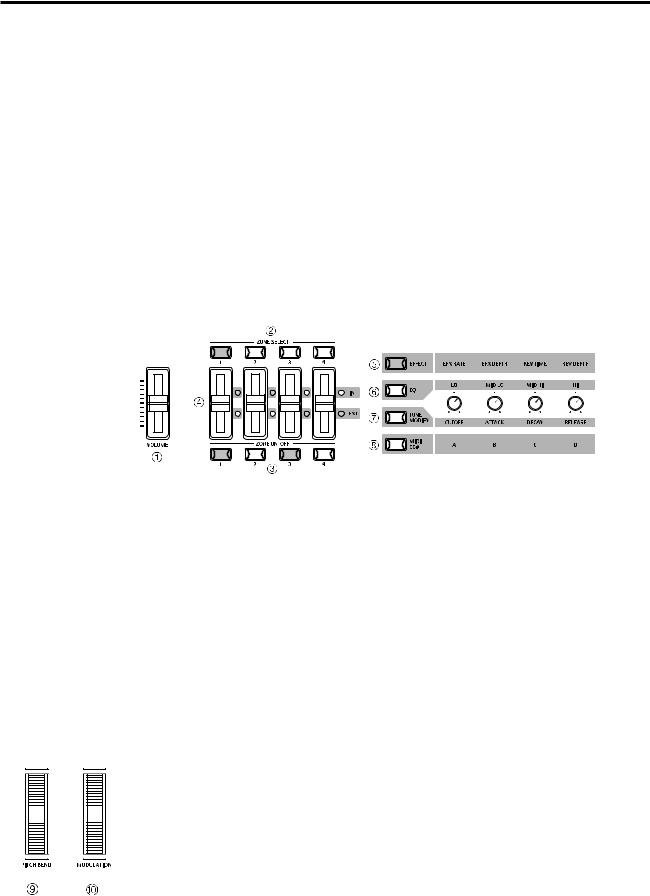
[FADER SECTION]
1. VOLUME Fader
The VOLUME fader controls the master volume level of the MP5.
2. ZONE SELECT buttons
The ZONE SELECT buttons are used to select one of the four zones for editing. Only one zone can be selected at a time. The front panel setting represents the current zone status.
3. ON/OFF buttons
The ON/OFF buttons are used to turn zones ON/OFF. When the button is lit, the zone is active. Normally the button color is red, but when a zone is not using the full keyboard range the color will be green to indicate it.
4. FADERS (zone volume level control)
Each fader controls the volume level of a designated zone. When multiple zones are active, these faders can be used as an audio mixer.
[CONTROL KNOBS SECTION]
The four CONTROL KNOBS are multi-function real time controllers. The different functions can be selected using the four buttons to the left side of the CONTROL KNOBS. When a function is active, its button is lit. Touching any of these knobs will instantly change the display to the current knob function and value.
5. EFFECT button
When this button is lit, the CONTROL KNOBS will adjust the REVERB time, REVERB depth, EFX rate and EFX depth.
6. EQ button
When this button is lit, the CONTROL KNOBS will adjust the 4-band graphic equalizer.
7. TONE MODIFY button
When this button is lit, the CONTROL KNOBS will adjust the CUTOFF, ATTACK, DECAY and RELEASE Levels for the selected zone.
8. MIDI CC# button
When this button is lit, MIDI control changes are sent from the MP5 to the MIDI device specified by the selected zone. Some control changes can also be used with the internal sounds.
[WHEEL CONTROLLERS]
9. PITCH BEND
This control wheel smoothly bends the pitch Up or Down from its current value.
10. MODULATION
This control wheel controls the modulation (vibrato) depth. Moving the wheel forward increases the vibrato depth.
10
[EFFECT BUTTONS]
11. SW button
This button turns the assigned function ON or OFF. Many different functions can be assigned to this switch for your convenience.
When in edit mode, pressing the SW button will exit from edit mode.
12. EFX button
This button turns the EFX ON or OFF for the selected zone.
13. REVERB button
This button turns the REVERB ON or OFF for the selected zone.
To change the function or type assigned to the above buttons, press and hold the desired button to display the currently selected function or type, then use the VALUE buttons to change it.
[MENU BUTTONS]
14. MENU buttons
The MENU buttons are used to enter the edit mode and scroll through all the various parameters of the MP5. To change a parameter value, use the VALUE buttons.
[DISPLAY]
15. DISPLAY
[VALUE BUTTONS]
16. VALUE buttons
The VALUE buttons are used to change the value of the current parameter as indicated on the DISPLAY.
[SOUND SELECTION & SETUP SELECTION]
17. SOUND button
The SOUND button switches the MP5 to the SOUND mode. The PATCH buttons will now select any of the 256 internal sounds.
18. SETUP button
The SETUP button switches the MP5 to the SETUP mode. The PATCH buttons will now select any of the 256 SETUPs.
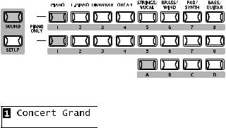
19. SOUND SELECT buttons
The SOUND SELECT buttons are organized in two rows of eight buttons and one row of four ones. In SOUND mode the upper row of buttons is used to select a sound category and the second & third rows of buttons is used to select the different internal sounds within each category. In SETUP mode the upper row of buttons is used to select a bank and the second & third rows of buttons is used to select the different SETUPs within each bank.
[OTHERS]
20. STORE button
The STORE button is used to store the settings of the MP5.
21. SYSTEM button
The SYSTEM button is used to set the system parameters of the MP5.
22. TRANSPOSE button
The TRANSPOSE button is used to turn the TRANSPOSE function ON/OFF.
11
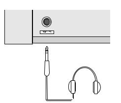
1.2 HEADPHONE JACK
The headphone jack is located in front at the left end of the key slip. Use a headphone with a standard stereo 1/4 inch phone jack.
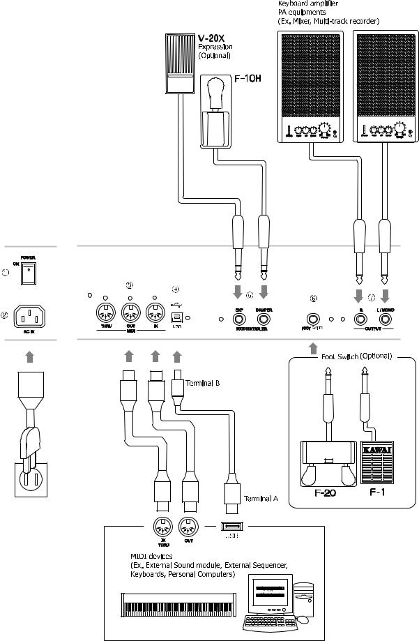
1.3REAR PANEL
1.POWER SWITCH
Turns the MP5 ON or OFF.
2. POWER RECEPTACLE
Connect the power cable, which is included in the MP5 package, to this receptacle.
3. MIDI JACKS
These jacks are used to connect the MP5 with external MIDI devices such as a MIDI sound module or a MIDI sequencer.
4. USB JACK
This jack is used to connect the MP5 with a personal computer. See page60 for details.
5. FOOT CONTROLLERS
EXP JACK
An expression pedal can be connected to this jack.
The expression pedal can be assigned to different MIDI control numbers or functions in the Menu.
DAMPER JACK
This jack is used to connect the Foot Pedal included with the MP5 (KAWAI F-10H).
6. FOOT SWITCH
A momentary footswitch can be connected to this jack (EX: KAWAI F-1 or F-20). The FootSwitch can be assigned to different MIDI control numbers or functions in the Menu. When using the KAWAI F-20. The right pedal works as a Foot Switch, and the left pedal works as a Soft pedal. When the Rotary EFX is in use, the Soft pedal changes between Fast & Slow Rotor speeds.
7. OUTPUTS
R, L/MONO OUTPUTS
The R, L/MONO outputs are used to connect the MP5 to a musical instrument amplifier using standard 1/4 inch phone jacks. The R, L/MONO outputs can also be used to connect the MP5 to a PA system or recording console.
12
13 |

2.Basic Operations
2.1Getting Ready
Since the MP5 has no built-in speakers, you will need to connect a mixer, keyboard amplifier or headphones in order to listen.
Turn the MP5 on, using the POWER SWITCH on the rear panel.
It is recommended to turn the MP5 on before turning on any amplifiers in order to avoid switching noise.
What you need to know before starting:
Please read this part for a better understanding of the MP5 structure.
The MP5’s SOUND and SETUP modes are largely the same. The main difference between the two is that SETUP is used to recall stored SETUPs. Edits and changes can be made freely in either mode, using the 4 faders, 4 knobs and MENU functions, however edits made in SOUND mode will be lost when the power is turned OFF and must therefore be stored in SETUP mode.
In order to start from scratch, use the SOUND mode and press PIANO ONLY first.
In order to modify a SETUP, select the desired SETUP, perform any edits, and store the changes as a SETUP.
If selected sounds do not sound correct, it is possible that parameters (knobs etc.) were edited. To restore sounds to their default setting, use the PIANO ONLY function, then re-select the desired sound.
14
2.2 Selecting a Sound
The MP5 always starts up in SOUND mode when the power is turned ON. The SOUND button will be lit to indicate SOUND mode is active.
Operation 1
Select the sound category by pressing a sound select button in the top row. There are 3 rows of sound select buttons, the top row is for selecting a sound category and the second and third rows are for selecting a variation.
For example, to select "60’s EP2", first press the E.PIANO in the top row and the first sound in the E.PIANO category "Classic EP" is recalled. (If any other variation was selected before, the last selected sound is recalled as long as the power is on.)
Operation 2
Select the first variation by pressing a sound select button in the second row. Press one of the 1-8 buttons in the second row. If you press 3, the variation 3 "60’s EP" is recalled. (If any other variation was selected before, the last selected sound is recalled as long as the power is on.)
Operation 3
Select the second variation by pressing a sound select button in the third row. Press one of the A-D buttons in the second row. If you press B, a variation sound "60’s EP2" is recalled.
Select the variations with the sound select buttons in the second and third rows.
The display shows the currently selected sound name.
Note:
Internal sounds or Setups can be also selected using the VALUE buttons.
You should also listen to the preprogrammed Setups.
Setups are organized in 8 Banks with 32 Numbers each (total 256 Setups). Press the SETUP button to change to SETUP mode and select a Setup by pressing one of the Bank buttons in the upper row followed by a Number button in the second and third row.
The display shows the currently selected Setup name.
15
In Sound mode, the “1” in the display indicates that the zone 1 is currently selected.
When the multitimbre is off, the default settings of the zones are as follows.
It is recomended for simple MIDI transmit/receive use on stage etc.
The default TXchannel is System Ch (see page45).
|
|
|
|
|
|
|
|
|
|
|
|
|
Zone 1 |
Internal |
On |
(Plays internal sound) |
|
|
|
|
|
|
|
|
|
|
|
|
|
Zone 2 |
Internal |
Off |
(Muted) |
|
|
|
|
|
|
|
|
|
|
|
|
|
||||
|
|
|
|
|
|
|
|
|
|
|
|
|
Zone 3 |
External |
On |
(Plays external device) |
|
|
|
|
|
|
|
|
|
|
|
|
|
Zone 4 |
External |
Off |
(Muted) |
|
|
|
|
|
|
|
|
|
|
|
|
|
When the multitimbre is on, the default settings of the zones are as follows.
It is recomended for recording/playback with PC or sequencer.
The default TXchannel is System Ch (see page45).
The system channel mode is Panel:
|
|
|
|
|
|
|
|
|
|
|
|
|
|
|
|
|
|
|
Zone 1 |
Both |
On |
(Plays internal sound & external device) |
|
|
|
|
|
|
|
|
|
|
|
|
|
|
|
|
|
|
|
Zone 2 |
int |
Off |
(Muted) |
|
|
|
|
|
|
|
|
|
|
|
|
|
|
|
|
|
|
|
Zone 3 |
int |
Off |
(Muted) |
|
|
|
|
|
|
|
|
|
|
|
|
|
|
|
|
|
|
|
Zone 4 |
int |
Off |
(Muted) |
|
|
|
|
|
|
|
|
|
|
|
|
|
|
|
|
|
|
|
||||
|
|
|
|
|
|
|
|
|
|
|
|
|
|
|
|
|
|
|
The system channel mode is Normal: |
|||
|
|
|
|
|
|
|
|
|
|
|
|
|
|
|
|
|
|
|
||||
|
|
|
|
|
|
|
|
|
|
|
|
|
|
|
|
|
|
|
||||
|
|
|
|
|
|
|
|
|
|
|
|
|
|
|
|
|
|
|
Zone 1 |
Both |
On |
(Plays internal sound & external device) |
|
|
|
|
|
|
|
|
|
|
|
|
|
|
|
|
|
|
|
||||
|
|
|
|
|
|
|
|
|
|
|
|
|
|
|
|
|
|
|
Zone 2 |
Both |
Off |
(Muted) |
|
|
|
|
|
|
|
|
|
|
|
|
|
|
|
|
|
|
|
Zone 3 |
Both |
Off |
(Muted) |
|
|
|
|
|
|
|
|
|
|
|
|
|
|
|
|
|
|
|
Zone 4 |
Both |
Off |
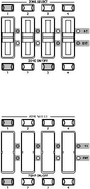
(Muted) |
The zone mode for each zone is indicated by the INT/EXT LED beside the faders. The zone status for each zone is indicated by the ZONE ON/OFF buttons. If the ZONE buttons is red, this zone is assigned to the entire keyrange of the MP5. If the button is green, the key range for that zone is less than the entire key range. You can check the key range setting by holding the SELECT button for the zone for 1 second.
16
2.3 Layer
Let’s try layering another sound. Turn the zone 2 on by pressing the ZONE ON/ OFF button for zone 2. The ZONE SELECT button for zone 2 is automatically selected and the display shows the sound name for zone 2.
Select the sound for zone 2 with the SOUND SELECT buttons as shown in the previous section.
Adjust the volume balance of zone 1 and 2 with the faders for each zone.
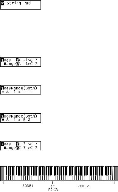
2.4 Split
Now let’s split the keyboard and play different sounds in upper and lower sections.
Press and hold the ZONE SELECT button for zone 1. The display shows the key range for zone 1 as follows.
While still holding down the ZONE SELECT button for zone 1, press the lowest note on the keyboard. The display changes as follows.
While still holding down the ZONE SELECT button for zone 1, select the highest note for zone 1, for example, B2 by pressing B2 key on the keyboard.
Repeat the same procedure for zone 2 while holding down the ZONE SELECT button for zone 2 and set the key range from C3 to C7.
Now the keyboard is split as follows.
Note:
In this method, the key ranges for internal and external zones always change together. If you want individual settings, use the Key Range Hi/Lo parameter in MENU (see page36).
17
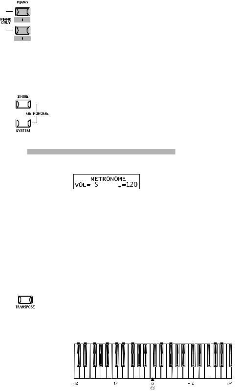
2.5 Piano Only
The Piano Only function lets you quickly return the MP5 sounds to the default settings.
Press the PIANO button and the SOUND SELECT button 1 simultaneously. All the current settings (except for SYSTEM settings) will go back to original and only Concert Grand sound can be played on the whole keyboard.
Note:
You may use this function also as a kind of Panic or Reset button. Also it is a good starting point to create Setups from scratch.
2.6 Metronome
A metronome is available on the MP5.
Press the STORE and SYSTEM buttons simultaneously to start the metronome. Press the STORE or SYSTEM button to stop the metronome.
Changing the Tempo/Volume
The display will show as follows.
Use the VALUE buttons to change the tempo.
Use the MENU buttons to change the volume.
Note:
The metronome tempo is also used as MIDI clock tempo to control an external sequencer. See page24 for details.
2.7 Transpose
When the Transpose function is “ON” the MP5’s key can be raised or lowered in half steps. The available range of transposition is 24 semitones, either up or down.
While holding down the TRANSPOSE button, press any key on the MP5 keyboard to select a new transposed key. Pressing the F key above middle C for example will transpose the MP5 UP to the key of F (+5 half steps).
The transpose amount can also be set using the VALUE buttons.
While holding the TRANSPOSE button down, press the VALUE buttons to change the transpose amount.
18
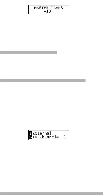
The display shows the current TRANSPOSE amount when the TRANSPOSE button is held down. A value of “0” indicates no transposition.
2.8 Using the MP5 as a MIDI controller
The MP5 can control external devices via MIDI.
MIDI Connection
Connect the MIDI OUT on the MP5 to the MIDI IN on an external MIDI device with a MIDI cable.
Selecting the MIDI Channel
The MIDI Transmit Channel of the MP5 must be matched with the Receive Channel of any MIDI devices connected to the MP5.
Select zone 3 by pressing the ZONE SELECT button 3. (Zone 3 is set to external as default setting.)
Press the MENU-UP button until “TX Channel” (Transmit Channel) appears on the display.
Use the VALUE buttons to choose a MIDI Transmit Channel from 1 to 16.
To exit from MENU, press the EXIT(SW) button.
Any notes played on the keyboard or any movements of the Knobs, sliders, etc. will be transmitted to any external MIDI devices connected to the MIDI out of the MP5 on the selected MIDI channel.
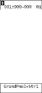
Sending Program Change Number
The MP5 can send MIDI program change numbers from 1 to 256 and Bank number LSB from 0 to 1 in SOUND mode. Simply press the SOUND SELECT buttons and the corresponding program number will be transmitted. See the program number table below.
19
UPPER |
SECOND |
THIRD |
PROG#:MSB-LSB |
1 |
1 |
A |
001:000-000 |
1 |
1 |
B |
002:000-000 |
1 |
1 |
C |
003:000-000 |
1 |
1 |
D |
004:000-000 |
1 |
2 |
A~D |
005:000-000 ~ 008:000-000 |
1 |
3 |
A~D |
009:000-000 ~ 012:000-000 |
1 |
4 |
A~D |
013:000-000 ~ 016:000-000 |
1 |
5 |
A~D |
017:000-000 ~ 020:000-000 |
1 |
6 |
A~D |
021:000-000 ~ 024:000-000 |
1 |
7 |
A~D |
025:000-000 ~ 028:000-000 |
1 |
8 |
A~D |
029:000-000 ~ 032:000-000 |
2 |
1~8 |
A~D |
033:000-000 ~ 064:000-000 |
3 |
1~8 |
A~D |
065:000-000 ~ 096:000-000 |
4 |
1~8 |
A~D |
097:000-000 ~ 128:000-000 |
5 |
1~8 |
A~D |
001:000-001 ~ 032:000-001 |
6 |
1~8 |
A~D |
033:000-001 ~ 064:000-001 |
7 |
1~8 |
A~D |
065:000-001 ~ 096:000-001 |
8 |
1~8 |
A~D |
097:000-001 ~ 128:000-001 |
The transmitted program number is shown in the display.
You can also send program change numbers by using VALUE buttons.
Note:
Full program change numbers including bank numbers can be transmitted by setting them in MENU and saving it as a SETUP. See page35 for details.
2.9 Selecting a SETUP
The MP5 offers 256 preset combinations of the panel settings called SETUPs. To select a SETUP, press the SETUP button. Now the SOUND SELECT buttons are used to select a SETUP. Use a combination of the numbers in the upper, second and third rows to select a desired SETUP. The display will show the selected SETUP name.
To check the sound (internal) or program number (external) assigned to each zone, press the ZONE SELECT button. The display briefly shows the assigned sound name or program number, and then automatically returns to the SETUP name in a few seconds.
If you hold a ZONE SELECT button for 2 seconds the display will show you the key range information for that zone. You can also set the key range using the same procedure that is used in Sound mode.
20
3. SW Button
The SW button is a programmable realtime switch which can be assigned to one of 8 different functions.
Press and hold the SW button. The display shows the currently assigned function.
Press the SW button again to exit without changing the function.
Use the VALUE buttons to change the function. The display will automatically return to SOUND or SETUP mode after you change the function.
This function can be stored using the STORE button. (see page43)
When the MENU function is displayed, the SW button works as an EXIT button.
3.1 Panel Lock
You can lock the panel operation to avoid unnecessary changes to the settings by accident.
When the SW button is lit Panel Lock is ON.
Panel Lock On: All the operations except for keyboard, wheels, pedals and SW button are locked. The display shows as follows while the panel is locked.
Panel Lock Off: Panel Lock is canceled.
3.2 Touch Curve
You can temporary turn on/off the Touch Curve for example to play organ sounds correctly.
Touch Curve On: The display briefly shows the selected Touch Curve in the SYSTEM and the Touch Curve becomes active. If the selected Touch Curve in the SYSTEM is Off, the Normal Touch Curve becomes active.
Touch Curve Off: The display briefly shows as follows and the Touch Curve becomes Off.
3.3 Rotary Slow/Fast
You can switch the speed of roter between slow and fast when the Rotary effect is in use.
When the SW button is lit: The display briefly shows as follows and the rotary speed changes to fast.
21
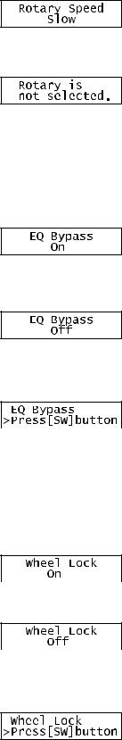
When the SW button is OFF: The display briefly shows as follows and the rotary speed changes to slow.
Note:
When the Rotary effect is not in use, the display briefly shows as follows.
3.4 EQ Bypass On/Off
You can temporarily bypass the EQ by turning the SW button on. When the SW button is lit the EQ Bypass is on.
EQ Bypass On: The display briefly shows as follows and the sound bypasses the EQ.
EQ Bypass Off: The display briefly shows as follows and the EQ comes back to active.
Note:
When the EQ Bypass is turned on and the EQ control knobs are used, the display briefly shows as follows.
3.5 Wheel Lock
You can lock the bender wheel and modulation wheel to avoid unnecessary movement by accident.
When the SW button is lit the Wheel Lock is on.
Wheel Lock On: The display briefly shows as follows and the wheels are locked.
Wheel Lock Off: The display briefly shows as follows and the wheels are unlocked.
Note:
When the Wheel Lock is turned on and the wheels are used, the display briefly shows as follows.
22
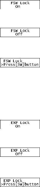
3.6 Foot Switch Lock
You can lock the assignable foot switch to avoid unnecessary movement by accident.
First, connect a foot switch to the FSW jack on the rear panel of the MP5. When the SW button is lit the Foot Switch Lock is on.
Foot Switch Lock On: The display briefly shows as follows and the assignable foot switch is locked.
Foot Switch Lock Off: The display briefly shows as follows and the assignable foot switch is unlocked.
Note:
When the FSW Lock is turned on and the foot switch is used, the display briefly shows as follows.
3.7 Expression Pedal Lock
You can lock the expression pedal to avoid unnecessary movement by accident. First, connect an expression pedal to the EXP jack on the rear panel of the MP5.
When the SW button is lit the Expression Pedal Lock is on
Expression Pedal Lock On: The display briefly shows as follows and the expression pedal is locked.
Expression Pedal Lock Off: The display briefly shows as follows and the expression pedal is unlocked.
Note:
When the EXP Lock is turned on and the expression pedal is used, the display briefly shows as follows.
23
 Loading...