

Page 1
01003
14.10
TABmaster Model 6715
Instruction Manual
Be sure to read this manual thoroughly before using the instrument ,
fully understand and pay attention to each cautions mentioned.
Please well -keeping this manual for long time service reference .
Page 2

CONTENTS
Product Configuration..................................................................................................................... 3
Caution................................................................................................................................. .......... 5
1. Introduction ................................................................................................................................ 7
1.1. Features............................................................................................................................. 7
1.2. Specifications ..................................................................................................................... 7
2. Outlook & Structure .................................................................................................................... 8
2.1. Base structure .................................................................................................................... 8
2.2. Micromanometer ............................................................................................................... 9
3. Settubg up ................................................................................................................................... 9
3.1. Capture Hood ................................................................................................ .................... 9
3.2. Velocity Grid................................................................ .....................................................10
3.3. Pitot tube .......................................................................................................................... 11
3.4. Micromanometer .............................................................................................................. 11
3.5. Shoulder Strap.................................................................................................................. 11
4. Operating Instruction .................................................................................................................12
4.1. Power supply ....................................................................................................................12
4.2. Start On / Power Off .........................................................................................................12
4.3. Keypad operation..............................................................................................................13
5. Function test...............................................................................................................................14
5.1. User Interface ................................................................ ...................................................14
5.2. Single Mode ......................................................................................................................15
5.3. Average Mode ...................................................................................................................15
5.4. Back Pressure Mode................................ ..........................................................................15
6. Menu setting...............................................................................................................................16
6.1. General setting..................................................................................................................17
6.1.1. Date ........................................................................................................................17
6.1.2. Time .......................................................................................................................17
6.1.3. Auto Off..................................................................................................................17
6.1.4. Backlighting ............................................................................................................18
6.1.5. Communication.......................................................................................................18
6.2. Test setting........................................................................................................................19
1
Page 3

6.2.1. Tools .......................................................................................................................19
6.2.2. ID application .........................................................................................................20
6.2.3. Test Mode ...............................................................................................................20
6.2.5. Data record .............................................................................................................21
6.2.6. Standard/Actual test ................................................................................................21
6.2.7. Compensation factor ...............................................................................................22
7 Error and Troubleshooting...........................................................................................................23
8 Warranty and Service ................................ .................................................................................. 24
8.1. Product Warranty .............................................................................................................24
8.2. After service......................................................................................................................24
2
Page 4

Item.
Qt’y
Micromanometer Model 6700
1
Instrument Base
1
Fabric Hood: 2ft×2ft
1
Carrying case
1
Portable handle
1
Frames
1
Poles
4
Communication cable
1
Calibration certificate
1
CD-Rom(Manual and software inside)
1
Quick-Guide
1
Item.
Specifications
Spare hood 2x2ft
Spare hood 2x4ft
Spare hood 1x4ft
Spare hood 3x2ft
Spare hood 3x3ft
Spare hood 500x500mm
Poles
Capture Hood Stand
Up to 3.4m with capture hood
Communication cable
Printer
AC adapter
DC5V
International plug adapter
Carrying case
Velocity Grid
Pitot tube (2.3 x 200mm)
Pitot tube (4 x 300mm)
Pitot tube (8 x 500mm)
Pressure tubing
2*250cm
Product Configuration.
6715 Standard:
6715 Optional Parts:
3
Page 5

Item.
Qt’y
Micromanometer Model 6700
1
Carrying case
1
Pressure tubing
2
Communication cable
1
Calibration certificate
1
CD-Rom(Manual and software inside)
1
Quick-Guide
1
Item.
Specifications
Velocity Grid
Pitot tube (2.3 x 200mm)
Pitot tube (4 x 300mm)
Pitot tube (8 x 500mm)
Pressure tubing
2*250cm
Shoulder Strap
Printer
AC adapter
DC5V
International plug adapter
Communication cable
6700 Standard:
6700 Optional Parts:
4
Page 6
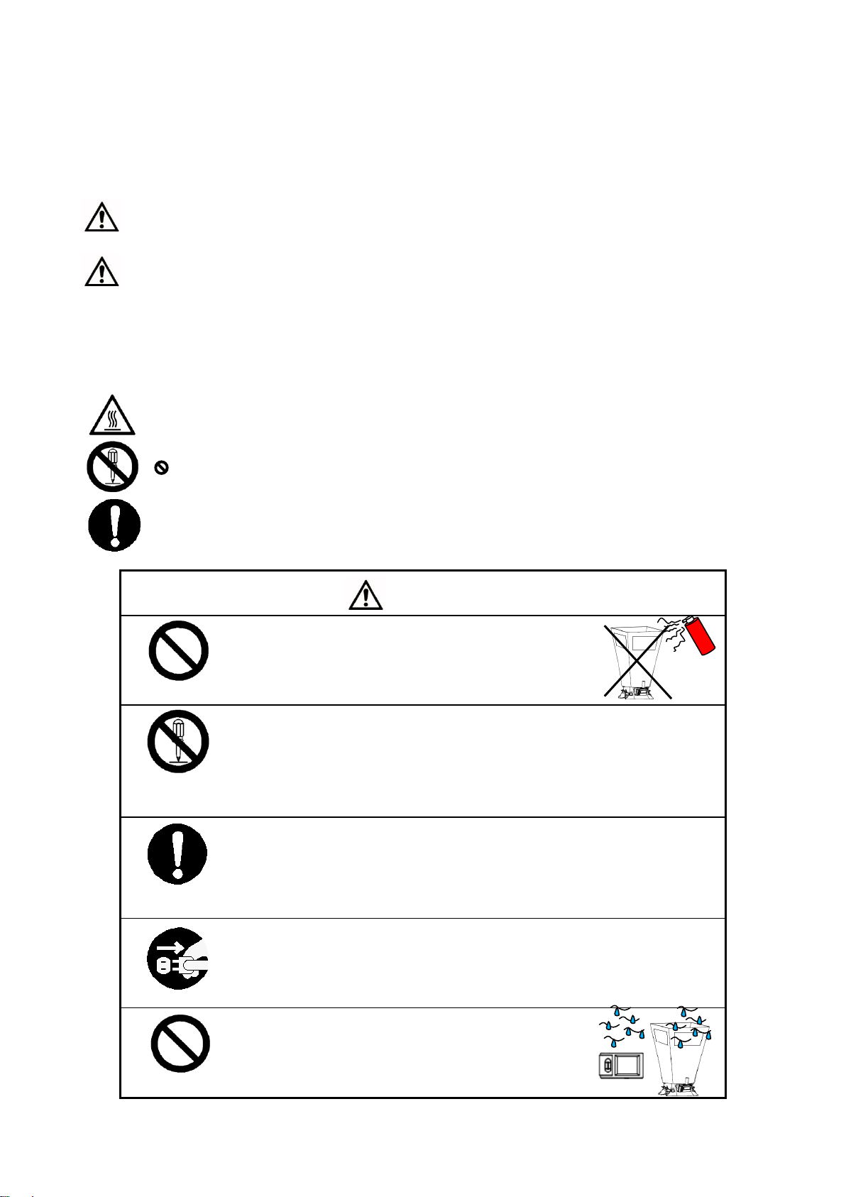
WARNING
Heated forbidden
○ Never bring the fabric hood to a flammable gas
atmosphere.
… otherwise, the heat may cause a fire or explosion.
Disassemble
prohibition
○ Do not disassembly or refit the instrument.
… otherwise, may cause the electric shock or a fire.
Using properly
○ Using properly under the instruction manual.
… otherwise, may cause sensor damaged or an electric shock even a fire.
Using properly
○ If abnormal smells, noises or smoke occur, or if liquid enters the instrument, pull out
the AC adapter and remove the batteries immediately. Then send it to the
maintenance Dept. of KANOMAX for after service.
… or, there is possible of an electric shock or a fire or instrument malfunction.
Forbidden
○ Do not e xpose the fabric hood, base and the ins trument
noumenon in the rain.
… otherwise, may cause an electric shock, an fire and an
person injure.
Caution.
The symbols for warning mentioned in this manual are defined below:
〔symbols classifications〕
Danger: To Prevent Serious Injury or Death
Warnings in this classification indicate a danger that may result in serious injury or death if not observed.
Caution: To Prevent Damage to the Product
Warnings in this classification indicate a risk of damage to the product that may void the product warranty if not
obse rved.
〔 Description of Symbols〕
△ This symbol indicates a condition that requires caution (including danger). The subject of each caution is
illustrated inside the triangle .
This symbol indicates a prohibition. Do not take the prohibited action shown inside or near this symbol .
● This symbol indicates a mandatory action. A specific action is given near the symbol.
5
Page 7
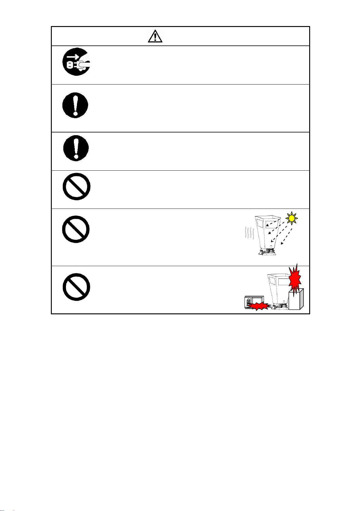
CAUTION
Using properly
○ Always unplug when the instrument not in use.
… Failure to do so may cause an electric shock, an fire or circuit damage.
Using properly
○ Remove the batteries when storing the instrument for a long period. Do not leave
the exhaused batteries in the battery comparement and e xchange the battereis on
time.
… Failure to do so may cause the batteries leakage and the instrument damage.
Using properly
○ Matching the correct AC adapter outward as reqested.
… or may cause the instrument damage.
Forbidden
○ Do not wipe the instrument with a vola tile solvent.
… the body may deform or deteriorate. Use a soft dry cloth to remove stains. If stains
persist, soak the cloth in a neutral detergent and wipe the instrument with the soft
cloth. Never use vola tile solvents such as thinner or benzene.
Forbidden
○ Do not use or lea ve the instrument in a high
temperature, high humidity or dusty environment. Do
not leave the instrument under direct sunlight.
… otherwise, the instrument may not function properly
out of the specified operating conditions or the inside
components damaged.
Forbidden
○ Never dropping the unit or placing heavy objects on it
… It may cause damage or malfunction to the instrument
6
Page 8

Items
Specifications
Air flow
Test range
40~4300 m3 /h
Accuracy
±3% of readings ± 8m3 /h(>85m3 /h)
Resolution
1 m3 /h
Air velocity
Test range
0.15~40 m/s(Pitot Tube)、 0.15~15 m/s(Velocity Grid)
Accuracy
±3% of readings ±0.05m/s(>0.25m/s)
Resolution
0.01m/s
Differential
pressure
Test range
-2500~2500 Pa
Accuracy
±0.25% of readings ±1Pa
Resolution
0.001 Pa
Temperature
Test range
0~60℃
Accuracy
±0.5℃
Resolution
0.1℃
Humidity
Test range
0~100%RH
Accuracy
±3%RH(10~90%RH)
Resolution
0.1%RH
Absolute
pressure
Test range
70~130 kPa
Accuracy
±2% of readings
Resolution
0.1 kPa
Operation Temp.
0~60℃(non condensing )
Storage Temp.
-20~70℃(non condensing)
Power Source
4 pcs of AA-size buttery ( approx. 9hrs available)or DC5V Adapter
Weight
3.6kg approx.
1. Introduction
TABmaster Model 6715 is a kind of intelligent test instrument with multi functional of airflow test, velocity
test and micro-Differential pressure test. It’s widely used in air flow and velocity testing of air - conditioning,
HAVC system and other places, especially for the high precision micro differential pressure test.
1.1. Features
3.5 inch true color LCD.
Available measuring the air flow, velocity, temperature and humidity at the same time.
Two kinds of tests are available of in flowing and exhaust flowing.
Back pressure compensation.
Ultra-large Storage capacity: 8000 records
Blue tooth communication makes remote monitoring and data transferring available.
Light weight, compact configuration for easy carrying.
Data printing or transferring to the computer.
1.2. Specifications
7
Page 9
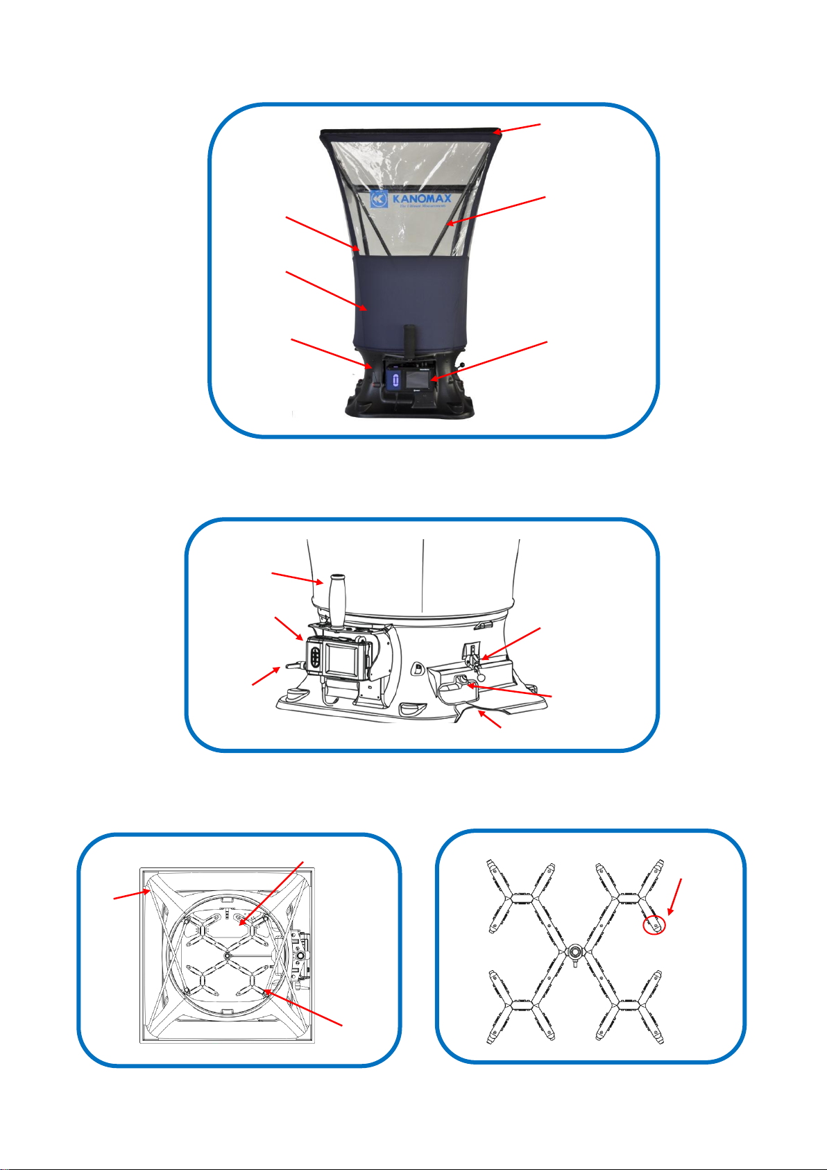
Testing
Fabric
Hood
Micromanometer
Pivot
Window
Frame
Poles
Instrument
Base
Poles
Grid
Back pressure plate
Test handle
Base buttom
Micromanometer
Back pressure
ON/OFF
Potable handle
Adjust handle
2. Outlook & Structure
2.1. Base structure
1.Outlook
2.Internal view 3.Grid
8
Page 10

Front view
Top view
Bottom view
Back
Cover lock
Mini USB Port
Power on/off
Air port (+)
Air port (-)
Keypad
Display LCD
Battery Compartment Cover
(1)
(2)
(3)
(4)
2.2. Micromanometer
3. Settubg up
3.1. Capture Hood
1.Fabric Hood & basement
、
Note:
1) Make sure the elastic band of the fabric hood is placed exactly as shown (Figure(3)) to ensure a good fit.
The elastic band must lineup with the top lip of the base as shown. If you don’t line it up correctly, the
hood might slide off the base when you insert the poles.
2) Use the 4 positioning holes on the base stitching as a guide to ensure the hood fully wraps around the
base..
2.Frame Poles
9
Page 11

①
②
(+) (-)
Note: The poles always cross in an “X” shape when assembling. To remove the poles, simply reverse the steps.
3.Potable handle
Note: Release the poles and portable handle when packing in the carring case to avoid case damaged.
4.Micromanometer & basement
Note: 1)Correct install the micromanometer to the base with the same S/N No.
2)Do not cross- insert the Air pines just refer to the figure as above.
3.2. Velocity Grid
Air velocity testing can be achieved when micromanometer work together with the velocity Grid.
10
Page 12

Device
under test
(+)( -)
Static pressure
port
Testing point
(+)( -)
(+)( -)
Handle
Grid
Note: Mounting angle between the Grid and handle can be adjusted as request.
3.3. Pitot tube
Air flow and velocity testing can be achieved when micromanometer work together with Pitot tube.
3.4. Micromanometer
Differential pressure testing can be achieved by using the micromanometer.
3.5. Shoulder Strap
When testing by Velocity Grid、Pitot tube、Micromanometer as the tool, for convenient view and easy
operation, the shoulder strap can be fit for using.
11
Page 13

①
②
③
Power off
4. Operating Instruction
4.1. Power supply
1.Power by AC adapter. AC adapter will be as the priority power supply when the AC adapter and batteries are
all available using. The specification of the AC adapter is: I/P:AC 110-240V 50/60HZ O/P:DC 5V/2A。
1)AC adapter for the master 2)AC adapter for Capture Hood
2.Power by battery
4 AA-size batteries can be used for a power supply.
Press the compartment cover lock (refer to figure indicating ①/②), and then slide the cover off to open
the battery compartment。
Put 4 AA-size batteries in and make certain the batteries are correctly oriented.
New alkaline battery or rechargeable Ni-MH battery can be used. Never mix battery types, or battery
leakage or damage to the instrument may occur.
Replace the compartment cover (refer to figure ③). The compartment cover will be automatically locked.
When power is supplied with batteries, the current charge value will be displayed on the upper of the LCD.
When the batteries run out of power, the instrument will turn off.
Note:
1) Do not test with low battery power.
2) Do not mixing use full power battery with low power ones for ensure testing well.
3) Change the batteries in time when power shows low for ensure testing well.
4.2. Start On / Power Off
12
Page 14

2014 / 03 / 20
13 : 10
20.5
℃
30.7
%RH
m
3
/h
Atmos:kPa
Ready
ID:
Cycle:
Mode:
01
001
Single
START
SAVE
MENU
99.0
POWER
START/STOP
SAVE
UP/SAVE
DOWN
SET/MENU/OK
START/STOP/
BACK/EXIT/ESC
1. Start On
Press button【POWER】for 2 seconds for start On, displaying “ KANOMAX” then enter into the testing
interface.
2. Power Off
Press【POWER】for 2 seconds, shut down and power off.
4.3. Keypad operation
Keypad panel includes control buttons, back-pressure switch and LCD adjusting keys.
1. Control buttons:
UP:Value increasing or Cursors upward moving.
SAVE:Save the current test results
SET:Store changes or enter into the selected option’s next level interface
MENU:On the main screen holding this down for 2 seconds will enter into the main “MENU”
OK:In the “General Setting”, pressing for 2 seconds will save the date or time ;
While in the “Record Processing”, pressing for 2 seconds will delete saved data.
START:Begin a measurement in main menu
STOP:Stop a measurement in main menu
BACK:Cancel or end an operation or return to the previous screen
EXIT:Return to the main menu
ESC:Stop printing when printing
DOWN::Value decreasing or Cursors downward moving
2. Back pressure switch for on/off
Note :
1) If you are not in the back pressure mode, shut down the back pressure plate and lock the
switch to avoid testing errors.
2) If the airflow is greater than 1500m
recommended according to testing procedures.
3
/h (883CFM), testing in back-pressure Mode is
13
Page 15

Back pressure
On
Back pressure
Off
2014 / 03 / 20
13 : 10
20.5
℃
30.7
%RH
m3/h
Atmos: kPa
Ready
ID:
Cycle:
Mode:
01
001
Single
START
SAVE
MENU
99.0
B C D E A
I H G F J
3.LCD adjusting
Note :
1)Please switching the handle slow gently during LCD adjusting.
2)Stop turning when reach to the bound, for avoiding over turning and handle falling down.
5. Function test
Besides the airflow test, if along with other optional products, test air velocity and micro -differential
pressure is available.
5.1. User Interface
Testing information, parameter settings and the testing conditions will be displayed on the main interface.
A. Date and time —— real-time display the current date and time
B. Testing data display —— airflow 、air velocity 、differential pressure and etc.
C. Tools icon —— working tools display
D. Testing condition —— temperature 、humidity or absolute pressure displaying according to the
14
Page 16

2014 / 03 / 20
13 : 10
20.5
℃
30.7
%RH
m3/h
Atmos: kPa
Waiting...
ID:
Cycle:
Mode:
01
001
Avg
99.0
STOP
SAVE
MENU
2014 / 03 / 20
13 : 10
20.5
℃
30.7
%RH
m3/h
Atmos: kPa
32
ID:
Cycle:
Mode:
01
001
Avg
99.0
STOP
SAVE
MENU
1.Ready for testing
2. Testing
3. test output
2014 / 03 / 20
13 : 10
20.5
℃
30.7
%RH
m3/h
Atmos: kPa
31
ID:
Cycle:
Mode:
01
001
Avg
99.0
STOP
SAVE
MENU
4. testing stop
STOP
2014 / 03 / 20
13 : 10
20.5
℃
30.7
%RH
m3/h
Atmos: kPa
Ready
ID:
Cycle:
Mode:
01
001
Avg
START
SAVE
MENU
99.0
START
2014 / 03 / 20
13 : 10
20.5
℃
30.7
%RH
m3/h
Atmos: kPa
Ready
ID:
Cycle:
Mode:
01
001
Single
START
SAVE
MENU
99.0
2014 / 03 / 20
13 : 10
20.5
℃
30.7
%RH
m3/h
Atmos: kPa
Waiting...
ID:
Cycle:
Mode:
01
001
Single
99.0
STOP
SAVE
MENU
2014 / 03 / 20
13 : 10
20.5
℃
30.7
%RH
m3/h
Atmos: kPa
32
ID:
Cycle:
Mode:
01
001
Single
99.0
START
SAVE
MENU
START
1. Ready for testing
2. Testing
3. test output
working tools.
E. Keypad —— current status indicating and the grey state is not available.
F. Testing mode —— display the current testing mode
G. Cycle—— recorded Cycle quantity
H. ID—— current ID quantity
I. Power supply —— AC adapter or batteries
J. Blue tooth status —— when blue tooth working, the icon display or no icon display with closed.
5.2. Single Mode
Note:
1) START: Left-button for the Micromanometer or instrument base
2) After testing start for about 8s with stably measuring,output displaying the test data and testing wind
direction.
3) Testing stop when finish outputting.
4) Press SAVE for data record with adding 1 to the Cycle value.
5) Same testing method with the capture hood when using the Velocity Grid、Pitot、Micromanometer.
5.3. Average Mode
Note:
1) START: Left-button for the Micromanometer or instrument base.
5.4. Back Pressure Mode
2) After testing start for about 8s with stably measuring , output displaying the test data for the first time.
3) Go on the testing with frequency of 1s for data updating.
4) The continuously outputting is as the average data and be related with the “AvgTime” set by user. More
larger of the value of“AvgTime” will get more stable of the testing data.
5) If auto-save function On, testing data will be recorded automatically according to the setting “AutoSave”
and value of “Cycle” will be added automatically.
6) Press “STOP”, testing stop. And “STOP” will be as the Left-button for the Micromanometer or instrument
base.
7) Same testing method with the capture hood when using the Velocity Grid、Pitot、Micromanometer.
15
Page 17

MENU
General Setting
Test Setting
UP
DOWN
OK
EXIT
SET
2014 / 03 / 20
13 : 10
20.5
℃
30.7
%RH
m3/h
Atmos: kPa
Ready
ID:
Cycle:
Mode:
01
001
Avg
START
SAVE
MENU
99.0
(1)2 optional settings:
1)Basic setting
2)Test setting
3)Working tool displaying below
2s
4. switch on Back-Pressure Plate
5. testing ready
6. testing
2. Testing
1.Ready for testing
7. test output
8. shut off the plate
9. testing ready
2014 / 03 / 20
13 : 10
20.5
℃
30.7
%RH
m3/h
Atmos: kPa
Ready
ID:
Cycle:
Mode:
01
001
B.P
START
SAVE
MENU
99.0
2014 / 03 / 20
13 : 10
20.5
℃
30.7
%RH
m3/h
Atmos: kPa
2000
ID:
Cycle:
Mode:
01
001
B.P
99.0
START
SAVE
MENU
3. Back-pressure On promoting
2014 / 03 / 20
13 : 10
20.5
℃
30.7
%RH
m3/h
Atmos: kPa
Ready
ID:
Cycle:
Mode:
01
001
B.P
START
SAVE
MENU
99.0
2014 / 03 / 20
13 : 10
20.5
℃
30.7
%RH
m3/h
Atmos: kPa
Open Flap !
ID:
Cycle:
Mode:
01
001
B.P
START
SAVE
MENU
99.0
2014 / 03 / 20
13 : 10
20.5
℃
30.7
%RH
m3/h
Atmos: kPa
Waiting...
ID:
Cycle:
Mode:
01
001
B.P
99.0
STOP
SAVE
MENU
START
2014 / 03 / 20
13 : 10
20.5
℃
30.7
%RH
m3/h
Atmos: kPa
Ready
ID:
Cycle:
Mode:
01
001
B.P
START
SAVE
MENU
99.0
2014 / 03 / 20
13 : 10
20.5
℃
30.7
%RH
m3/h
Atmos: kPa
Waiting...
ID:
Cycle:
Mode:
01
001
B.P
99.0
STOP
SAVE
MENU
START
In order to reduce the measure error of the pressure loss,which causing from the hood to the system and
get the more real air flow, we suggest testing under the Back Pressure Mode when air flow more than 1500
m3/h.
Note:
1) START: Left-button for the Micromanometer or instrument base.
2) After testing start for about 8s , indicating “Open Flap”. It’s time for switching on the Back-Pressure Plate
as needed.
3) When Back-Pressure Plate opened On, tip of “Open Flap” disappear.
4) Press START for about 8s, testing stop, real airflow outputting with back pressure compensation.
5) Press SAVE for testing data record and the meanwhile, value Cycle added 1.
6) When select Velocity Grid、Pitot tube、Micromanometer for testing, Back-Pressure compensation will be
not available.
6. Menu setting
when stop for ready, press for 2s for enter into the menu.
16
Page 18

MENU
General Setting
Test Setting
UP
DOWN
OK
EXIT
SET
(1)Basic setting:
1)Date
2)Time
3)Auto Shut
4)Backlight
5)Communicate
2s
(1) press or for data modify.
(2)press , for selecting Year/Month/day.
(3)Press for 2s for save settings.
(4)Press for quit.
General Setting
1.
2.
3.
4.
5.
Date
Time
Auto Shut
Backlight
Communicate
UP
DOWN
OK
BACK
SET
2014 / 03 / 20
13 : 10
Off
High
General Setting
1.
2.
3.
4.
5.
Date
Time
Auto Shut
Backlight
Communicate
UP
DOWN
OK
BACK
SET
20 / 03 / 20
13 : 10
Off
High
14
General Setting
1.
2.
3.
4.
5.
Date
Time
Auto Shut
Backlight
Communicate
UP
DOWN
OK
BACK
SET
2014 / 04 / 01
13 : 10
Off
High
General Setting
1.
2.
3.
4.
5.
Date
Time
Auto Shut
Backlight
Communicate
UP
DOWN
OK
BACK
SET
2014 / 04 / 01
13 : 10
Off
High
01
General Setting
1.
2.
3.
4.
5.
Date
Time
Auto Shut
Backlight
Communicate
UP
DOWN
OK
BACK
SET
2014 / 03 / 20
13 : 10
Off
High
2s
(1)Press or for data modify.
(2)Press for hour/minute selection.
(3)Press for 2s for save settings.
(4)Press for quit.
General Setting
1.
2.
3.
4.
5.
Data
Time
Auto Shut
Backlight
Communicate
UP
DOWN
OK
BACK
SET
2014 / 03 / 20
: 10
Off
High
13
General Setting
1.
2.
3.
4.
5.
Date
Time
Auto Shut
Backlight
Communicate
UP
DOWN
OK
BACK
SET
2014 / 03 / 20
13 : 10
Off
High
General Setting
1.
2.
3.
4.
5.
Date
Time
Auto Shut
Backlight
Communicate
UP
DOWN
OK
BACK
SET
2014 / 03 / 20
15 : 15
Off
High
General Setting
1.
2.
3.
4.
5.
Data
Time
Auto Shut
Backlight
Communicate
UP
DOWN
OK
BACK
SET
2014 / 03 / 20
15 : 15
Off
High
15
6.1. General setting
6.1.1. Date
6.1.2. Time
6.1.3. Auto Off
When instrument not in use, it will be turn off automatically according to Auto-Off time setting to avoid
power waste.
17
Page 19

(1)Press or for options change.
(2)Press for save settings .
(3)Press for quit.
(1)Press or for options change.
(2)Press for save settings .
(3)Press for quit.
General Setting
1.
2.
3.
4.
5.
Data
Time
Auto Shut
Backlight
Communicate
UP
DOWN
OK
BACK
SET
2014 / 03 / 20
13 : 10
Off
20 min
10 min
30 min
60 min
General Setting
1.
2.
3.
4.
5.
Data
Time
Auto Shut
Backlight
Communicate
UP
DOWN
OK
BACK
SET
2014 / 03 / 20
13 : 10
Off
20 min
10 min
30 min
60 min
General Setting
1.
2.
3.
4.
5.
Date
Time
Auto Shut
Backlight
Communicate
UP
DOWN
OK
BACK
SET
2014 / 03 / 20
13 : 10
Off
High
General Setting
1.
2.
3.
4.
5.
Date
Time
Auto Shut
Backlight
Communicate
UP
DOWN
OK
BACK
SET
2014 / 03 / 20
13 : 10
10 min
High
General Setting
1.
2.
3.
4.
5.
Date
Time
Auto Shut
Backlight
Communicate
UP
DOWN
OK
BACK
SET
2014 / 03 / 20
13 : 10
Off
High
General Setting
1.
2.
3.
4.
5.
Date
Time
Auto Shut
Backlight
Communicate
UP
DOWN
OK
BACK
SET
2014 / 03 / 20
13 : 10
Off
Low
High
Normal
General Setting
1.
2.
3.
4.
5.
Date
Time
Auto Shut
Backlight
Communicate
UP
DOWN
OK
BACK
SET
2014 / 03 / 20
13 : 10
Off
High
Low
Normal
General Setting
1.
2.
3.
4.
5.
Date
Time
Auto Shut
Backlight
Communicate
UP
DOWN
OK
BACK
SET
2014 / 03 / 20
13 : 10
Off
Low
6.1.4. Backlighting
Adjust the LCD lighting according to the environmental brightness for the best viewing. And meanwhile, the
lower the brightness, the less battery power will be needed.
6.1.5. Communication
Communicate with PC, printer and Bluetooth are available. Data transfer or remote monitoring is available
by selecting communicating way.
Note:
1)PC communication means to save the testing record to the computer. And the communication cable and
software reserved for data-fetching are necessary for using together. Refer to the << Manuel for Data
fetching Software>> .
2)For printing out the testing record, the optional printer and cables for special are necessary. Printer baud
rate is set to 19200 bps and Do not change it. Refer to the << Manuel for RD series Mini printer >> .
3)Bluetooth make the remote control and data monitoring available by Hand phone. And our APP software is
necessary for using together. Refer to the << Manuel for TAB Mobile>>.
4)Shut off the switch when not use the Bluetooth communication for improving battery life.
18
Page 20

2014 / 03 / 20
13 : 10
20.5
℃
30.7
%RH
m3/h
Atmos: kPa
32
ID:
Cycle:
Mode:
01
001
Avg
START
SAVE
OFF
99.0
2014 / 03 / 20
13 : 10
20.5
℃
30.7
%RH
m3/h
Atmos: kPa
32
ID:
Cycle:
Mode:
01
001
Avg
START
SAVE
MENU
99.0
2s
Communicate
1.
2.
3.
Computer
Printer
Bluetooth
UP
DOWN
OK
BACK
SET
Off
Print
1.2.Print By IDs
Print By Cycles
UP
DOWN
OK
BACK
SET
Communicate
1.
2.
3.
Computer
Printer
Bluetooth
UP
DOWN
OK
BACK
SET
Off
Communicate
1.
2.
3.
Computer
Printer
Bluetooth
UP
DOWN
OK
BACK
SET
Off
Computer
Comfirm the Connection
UP
DOWN
OK
BACK
SET
Waiting...
Communicate
1.
2.
3.
Computer
Printer
Bluetooth
UP
DOWN
OK
BACK
SET
On
General Setting
1.
2.
3.
4.
5.
Date
Time
Auto Shut
Backlight
Communicate
UP
DOWN
OK
BACK
SET
2014 / 03 / 20
13 : 10
Off
High
Test settings:
1)Select Tool
2)Test ID
3)Test Mode
4)Unit
5)Data Record
6)Standard/Actual testing
7)Compensation factor
MENU
General Setting
Test Setting
UP
DOWN
OK
EXIT
SET
Test Setting
1.
2.
3.
4.
5.
Select Tool
Test ID
Test Mode
Unit
Data Record
UP
DOWN
OK
BACK
SET
RunAvg
6.7.Std/Act
K factor
1.000
Act
5)If other settings need to be changed when Bluetooth successful communication, you need to shutdown
Bluetooth firstly then enter the menu to change other settings. Just as below shown:
6.2. Test setting
6.2.1. Tools
19
Page 21

(1)”Avg Time” is as a pe riod for
testing; the longer the time period,
the more s table the testing value will
be as spikes in airflow will be averaged
out over time.
(2)“ Auto Save” is a time interval for
automatic data recording during testing.
Tools
Test item
TABmaster
Air flow / Temperature / RH
Velocity Grid
Air velocity
Pitot tube
velocity
Micromanometer
Micro-differential pressure
(1)Press or for options change.
(2)Press for save settings .
(3)Press for quit.
Test Setting
1.
2.
3.
4.
5.
Select Tool
Test ID
Test Mode
Unit
Data Record
UP
DOWN
OK
BACK
SET
RunAvg
6.7.Std/Act
K factor
1.000
Act
Test Setting
1.
2.
3.
4.
5.
Select Tool
Test ID
Test Mode
Unit
Data Record
UP
DOWN
OK
BACK
SET
RunAvg
6.7.Std/Act
K factor
1.000
Act
Select Tool
1.
2.
3.
Capture Hood
Velocity Grid
Pitot
UP
DOWN
OK
BACK
SET
4.
Pressure
P
Select Tool
1.
2.
3.
Capture Hood
Velocity Grid
Pitot
UP
DOWN
OK
BACK
SET
4.
Pressure
P
(1) Test ID is up to 20.
(2) Set different Test ID for the different tool.
(3) 100 data records can be stored in a single
ID
Test ID
1.2.Select ID
Add New ID
01
UP
DOWN
OK
BACK
SET
No
Total ID:
20
Test Setting
1.
2.
3.
4.
5.
Select Tool
Test ID
Test Mode
Unit
Data Record
UP
DOWN
OK
BACK
SET
RunAvg
6.7.Std/Act
K factor
1.000
Act
Test Setting
UP
DOWN
OK
BACK
SET
RunAvg
Single
B.Prees
1.
2.
3.
4.
5.
Select Tool
Test ID
Test Mode
Unit
Data Record
6.7.Std/Act
K factor
1.000
Act
Test Setting
1.
2.
3.
4.
5.
Select Tool
Test ID
Test Mode
Unit
Data Record
UP
DOWN
OK
BACK
SET
Single
6.7.Std/Act
K factor
1.000
Act
Test Setting
UP
DOWN
OK
BACK
SET
RunAvg
Single
B.Prees
1.
2.
3.
4.
5.
Select Tool
Test ID
Test Mode
Unit
Data Record
6.7.Std/Act
K factor
1.000
Act
Test Setting
UP
DOWN
OK
BACK
SET
RunAvg
1.
2.
3.
Select Tool
Test ID
Test Mode
Avg Time: Sec
Auto Save: Off
03
Test Setting
UP
DOWN
OK
BACK
SET
RunAvg
1.
2.
3.
Select Tool
Test ID
Test Mode
Avg Time: Sec
Auto Save:
03
10 Sec
Off
20 Sec
30 Sec
60 Sec
Test Setting
1.
2.
3.
4.
5.
Select Tool
Test ID
Test Mode
Unit
Data Record
UP
DOWN
OK
BACK
SET
RunAvg
6.7.Std/Act
K factor
1.000
Act
The TABmaster model 6715 is an instrument for airflow, air temperature, and relative humidity
measurements. The optional accessories (Velocity Grid, Pitot tube, and M icromanometer) expand the
parameters that the instrument can measure. Refer to the Chapter 3 and 5 for details.
6.2.2. ID application
6.2.3. Test Mode
20
Page 22

(1)Press or for options change.
(2)Press for save settings .
(3)Press for quit.
Unit
1.
2.
3.
Airflow
Atoms
Temperature
℃
UP
DOWN
OK
BACK
SET
CFM
kPa
Unit
1.
2.
3.
Airflow
Atoms
Temperature
l/s
UP
DOWN
OK
BACK
SET
CFM
m3/h
lbs
Unit
1.
2.
3.
Airflow
Atoms
Temperature
℃
UP
DOWN
OK
BACK
SET
m3/h
kPa
Test Setting
1.
2.
3.
4.
5.
Select Tool
Test ID
Test Mode
Unit
Data Record
UP
DOWN
OK
BACK
SET
RunAvg
6.7.Std/Act
K factor
1.000
Act
Test Setting
1.
2.
3.
4.
5.
Select Tool
Test ID
Test Mode
Unit
Data Record
UP
DOWN
OK
BACK
SET
RunAvg
6.7.Std/Act
K factor
1.000
Act
Test Setting
1.
2.
3.
4.
5.
Select Tool
Test ID
Test Mode
Unit
Data Record
UP
DOWN
OK
BACK
SET
RunAvg
6.7.Std/Act
K factor
1.000
Std
Test Setting
1.
2.
3.
4.
5.
Select Tool
Test ID
Test Mode
Unit
Data Record
UP
DOWN
OK
BACK
SET
RunAvg
6.7.Std/Act
K factor
Std
Act
Test ID:
UP
DOWN
OK
BACK
SET
Total: 2001
Max:
Min :
Avg:
m3/h
m3/h
m3/h
0
0
0
Press [SET] See Cycle Data
Data Record
1.2.Display the Record
Delete the Record
UP
DOWN
OK
BACK
SET
Delete
1.
2.
3.
Delete All
Delete IDs
Select ID:
Delete Cycles
Select ID:
Select Cycle:
UP
DOWN
OK
BACK
SET
No
No
01
01
001
No
Cycle:
UP
DOWN
OK
BACK
SET
Total: 0101
AirFlow:
Atmos :
m3/h
℃
0
35.8
Temp:
Humidity:
Time:
101.3 kPa
%RH
21.1
2014 / 03 / 18
13 : 10 : 18
Std
Std/Act:
Data Record
UP
DOWN
OK
BACK
SET
1.2.Display the Record
Delete the Record
Test Setting
1.
2.
3.
4.
5.
Select Tool
Test ID
Test Mode
Unit
Data Record
UP
DOWN
OK
BACK
SET
RunAvg
6.7.Std/Act
K factor
1.000
Act
6.2.4. Units
6.2.5. Data record
Note:
1) Browsing or deleting test data in current testing tools is available for allowed.
2) Data exporting by communication function and deleting the non-valid data in time for the effective
storage space.
3) Pressing for 2 seconds will delete saved data.
6.2.6. Standard/Actual test
21
Page 23

(1)Press or for options change.
(2)Press for save settings .
(3)Press for quit.
Test Setting
1.
2.
3.
4.
5.
Select Tool
Test ID
Test Mode
Unit
Data Record
UP
DOWN
OK
BACK
SET
RunAvg
6.7.Std/Act
K factor
1.000
Act
8.
Temperature
23.5 ℃
Test Setting
1.
2.
3.
4.
5.
Select Tool
Test ID
Test Mode
Unit
Data Record
UP
DOWN
OK
BACK
SET
RunAvg
6.7.Std/Act
K factor
1.000
Act
8.
Temperature
℃
25.0
Test Setting
1.
2.
3.
4.
5.
Select Tool
Test ID
Test Mode
Unit
Data Record
UP
DOWN
OK
BACK
SET
RunAvg
6.7.Std/Act
K factor
1.000
Act
8.
Temperature
25.0 ℃
Test Setting
1.
2.
3.
4.
5.
Select Tool
Test ID
Test Mode
Unit
Data Record
UP
DOWN
OK
BACK
SET
RunAvg
6.7.Std/Act
K factor
1.000
Act
Test Setting
1.
2.
3.
4.
5.
Select Tool
Test ID
Test Mode
Unit
Data Record
UP
DOWN
OK
BACK
SET
RunAvg
6.7.Std/Act
K factor
1.000
Act
Test Setting
1.
2.
3.
4.
5.
Select Tool
Test ID
Test Mode
Unit
Data Record
UP
DOWN
OK
BACK
SET
RunAvg
6.7.Std/Act
K factor
1.010
Act
Test Setting
1.
2.
3.
4.
5.
Select Tool
Test ID
Test Mode
Unit
Data Record
UP
DOWN
OK
BACK
SET
RunAvg
6.7.Std/Act
K factor
1.010
Act
Note:
1) Standard Test (Std): in the condition of atmosphere 101.3kPa and temperature 21.1℃.
2) Actual Test(Act): in actual condition with the compensation for the atmosphere and temperature.
3) No Std/Act selection when in Micromanometer testing.
4) When doing actual testing under Velocity Matrix and pitot tube, manually input t he current
temperature is needed for the compensation. Refer to the figures as below:
6.2.7. Compensation factor
Note:
1) Under Capture Hood and Velocity Grid testing, K factor is used for testing data compensation in
order to get more accuracy result. And the testing range will be 0.500~1.500.
Note: K factor will affect the accuracy of measurement, so, it’s necessary for having the test bench for
standard reference and using with caution.
For example:
If the Capture Hood is as the selected testing tool, testing value by Model 6715 is 1000m3/h,
the standard airflow is 1020m3/h,at this point, K factor= standard value/testing value =1.020,input
this K factor to correct the accuracy of the measurement by Model 6715.
2) Under Pitot tube testing, K factor is the factory standard coefficient and each pitot with its own
independent factor.
3) No K factor setting under the micromanometer testing.
22
Page 24

Symptom
Possible causes
Corrective action
No display when power On
incorrect specification of the AC
Adapter
Check and refer to Chapter4.1
in Manuel
Battery installation error
Check and refer to Chapter4.1
in Manuel
Low or dead battery power
Replace the batteries
Display “Connect Error”
Connection cable loss with the
base
Reseat the connect cable
Display “DATA Error”
Back-Pressure mode using
incorrect
Refer to Chapter 5.4 in Manuel
Press “START” but no response
Low battery charge
Replace new batteries
Back Pressure Plate opened On
Shut off the plate
Testing record can not be saved
Over-limit Cycle quantity in
current ID
Add new ID or delete some
data
New ID can not be added
ID over-limit
Delete some ID
Current ID is without “Cycle”
Using the current ID
Printing unreadable code
Unmatched printer
Using our special optional
printer supplied by us.
Wrong baud rate setting
Reset referring to the Printer
Manuel
7 Error and Troubleshooting
23
Page 25

8 Warranty and Service
8.1. Product Warranty
The limited warranty set forth below is given by KANOMAX GROUP COMPANIES with respect to the
KANOMAX brand capture hood and other accessories (hereafter referred to as “PRODUCT”) purchased
directly from KANOMAX GROUP COMPANIES or from an authorized distributor.
Your PRODUCT, when delivered to you in new condition in its original container, is warranted against defects
in materials or workmanship as follows: for a period of one (1) year from the date of original purchase, defective
parts or a defective PRODUCT returned to KANOMAX GROUP COMPANIES, as applicable, and proven to be
defective upon inspection, will be exchanged for a new or comparable rebuilt parts, or a refurbished PRODUCT as
determined by KANOMAX GROUP COMPANIES. Warranty for such replacements s hall not extend the original
warranty period of the defective PRODUCT.
This limited warranty covers all defects encountered in normal use of the PRODUCT, and does not
apply in the following cases:
(1) Use of parts or supplies other than the PRODUCT sold by KANOMAX GROUP COMPANIES, which cause
damage to the PRODUCT or cause abnormally frequent service calls or service problems.
(2) If any PRODUCT has its serial number or date altered or removed.
(3) Loss of damage to the PRODUCT due to abuse, mishandling, alternation, improper packaging by the
owner, accident, natural disaster, electrical current fluctuations, failure to follow operation ,
maintenance or environmental instructions prescribed in the PRODUCT's operation manual provided by
KANOMAX GROUP COMPANIES, or service performed by other than KANOMAX GROUP COMPANIES.
NO IMPLIED WARRANTY, INCLUDING ANY IMPLIED WARRANTY OF MERCHANTABILITY OR FITNESS FOR A
PARTICULAR PURPOSE, APPLIES TO THE PRODUCT AFTER THE APPLICABLE PERIOD OF THE EXPRESS LIMITED
WARRANTY STATED ABOVE, AND NO OTHER EXPRESS WARRANTY OR GUARANTY, EXCEPT AS MENTIONED
ABOVE, GIVEN BY ANY PERSON OR ENTITY WITH RESPECT TO THE PRODUCT SHALL BIND KANOMAX GROUP
COMPANIES. KANOMAX GROUP COMPANIES SHALL NOT BE LIABLE FOR LOSS OF STORAGE CHARGES, LOSS
OR CORRUPTION OF DATA, OR ANY OTHER SPECIAL, INCIDENTAL OR CONSEQUENTIAL DAMAGES CAUSED BY
THE USE OR MISUSE OF, OR INABILITY TO USE, THE PRODUCT, REGARDLESS OF THE LEGAL THEORY ON
WHICH THE CLAIM IS BASED, AND EVEN IF KANOMAX GROUP COMPANIES HAS BEEN ADVISED OF THE
POSSIBILITY OF SUCH DAMAGES. IN NO EVENT SHALL RECOVERY OF ANY KIND AGAINST KANOMAX GROUP
COMPANIES BE GREATER IN AMOUNT THAN THE PURCHASE PRICE OF THE PRODUCT SOLD BY KANOMAX
GROUP COMPANIES AND CAUSING THE ALLEGED DAMAGE. WITHOUT LIMITING THE FOREGOING, THE
OWNER ASSUMES ALL RISK AND LIABILITY FOR LOSS, DAMAGE OF, OR INJURY TO THE OWNER AND THE
OWNER'S PROPERTY AND TO OTHERS AND THEIR PROPERTY ARISING OUT OF USE OR MISUSE OF, OR
INABILITY TO USE, THE PRODUCT NOT CAUSED DIRECTLY BY THE NEGLIGENCE OF KANOMAX GROUP
COMPANIES. THIS LIMITED WARRANTY SHALL NOT EXTEND TO ANYONE OTHER THAN THE ORIGINAL
PURCHASER OF THE PRODUCT, OR THE PERSON FOR WHOM IT WAS PURCHASED AS A GIFT, AND STATES THE
PURCHASER'S EXCLUSIVE REMEDY.
8.2. After service
When you have a problem with your instrument, please check out the “Common Trouble Shooting”
section first.
If that does not help, please contact your local distributor, or contacts on the last page.
During the warranty period, we will repair at no charge a product that proves to be defective due to
material or workmanship under normal use. (See Section 14.1 Warranty)
All return shipping charges are the responsibility of the customer.
24
Page 26

* PRODUCT NAME ----------
* Model No. --------- * Serial No. --------- * Description of the problem : ----------
* Data of Purchase: Day, Month and Year
Repair after warranty expiration:
Upon request, we will repair the instrument at the customer’s expense, if the instrument’s
performance is found to be recoverable by providing the repair.
Replacement parts are available for a minimum period of five (5) years after termination of production.
This storage period of replacement parts is considered as the period during which we can provide
repair service. For further information, please contact your local distributor, or contacts on the last page.
25
Page 27

Kanomax Group Companies
■ Americas, Europe, Mid-East, Africa, Oceania
KANOMAX USA, INC.
219 US Highway. 206, Andover, New Jersey 07821
TEL: 1-800-247-8887(USA) / 1-973-786-6386
FAX: 1-973-786-7586
URL: www.kanomax-usa.com
E-Mail: info@kanomax-usa.com
■ Japan & Asia
KANOMAX JAPAN, INC.
2-1 Shimizu Suita City, Osaka Japan 565-0805
TEL: 81-6-6877-0183
FAX: 81-6-6879-2080
URL: www.kanomax.co.jp
E-Mail: sales@kanomax.co.jp
■ China
Shenyang Kano Scientific Instrument Co., Ltd.
#2610,51 Wulihe Street Heping District, Shenyang City, PRC
TEL: 86-24-23845309
FAX: 86-24-23898417
URL: http://www.kanomax.com.cn/
E-Mail: sales@kanomax.com.cn
 Loading...