

Page 1

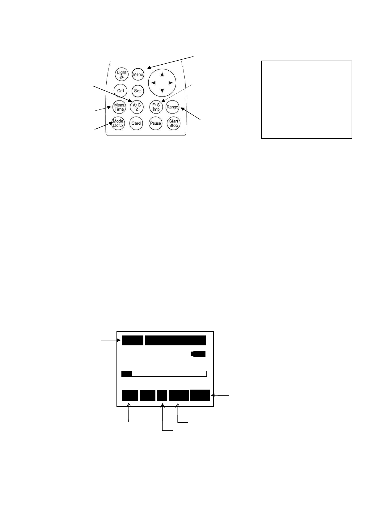
Sound level meter
MODEL 4431
Instruction manual
KANOMAX JAPAN INC.
Page 2

1
Components of this Instruction manual
This instruction manual refers to the functions of, and operating instructions for, Sound Level
Meter MODEL 4431 (abbreviated to “this equipment” in what follows)
This instruction manual consists of following chapters.
Outline
The components, characteristics, block diagram of this equipment are described
Locations and their functions
The names and functions of keys and terminals are briefly described.
Liquid crystal screen
The symbols displayed on the screen are described.
Preparation
The power supply, check before use, installation of this equipment, connection of cables and
various key setting are described.
Measurement
Basic idea of measurement method is described.
Recording
How to save or recall data is described.
Printing/Collecting
How to print or collect the measurement data is described.
Output terminal
Output terminal of this equipment is described.
Specification
The specification of this equipment is described.
Page 3
2
Safety precautions
To prevent bodily injury or damage to property, the following safety precautions must be
observed.
This manual contains important safety and operating instructions for this equipment.
Read all instructions, before using the instrument.
After reading all instructions, keep this manual for quick reference
1111....Expressions of safety instructions
WARNING
Calls attention to a procedure, practice, or condition that could possibly cause death or
bodily injury.
CAUTION
Calls attention to a procedure, practice, or condition that could possibly cause bodily
injury or damage to instrument.
NOTE
It is an advisory explanation to use this equipment correctly. (It is not a safety
instruction )
Page 4
3
2222....Important safety instructions
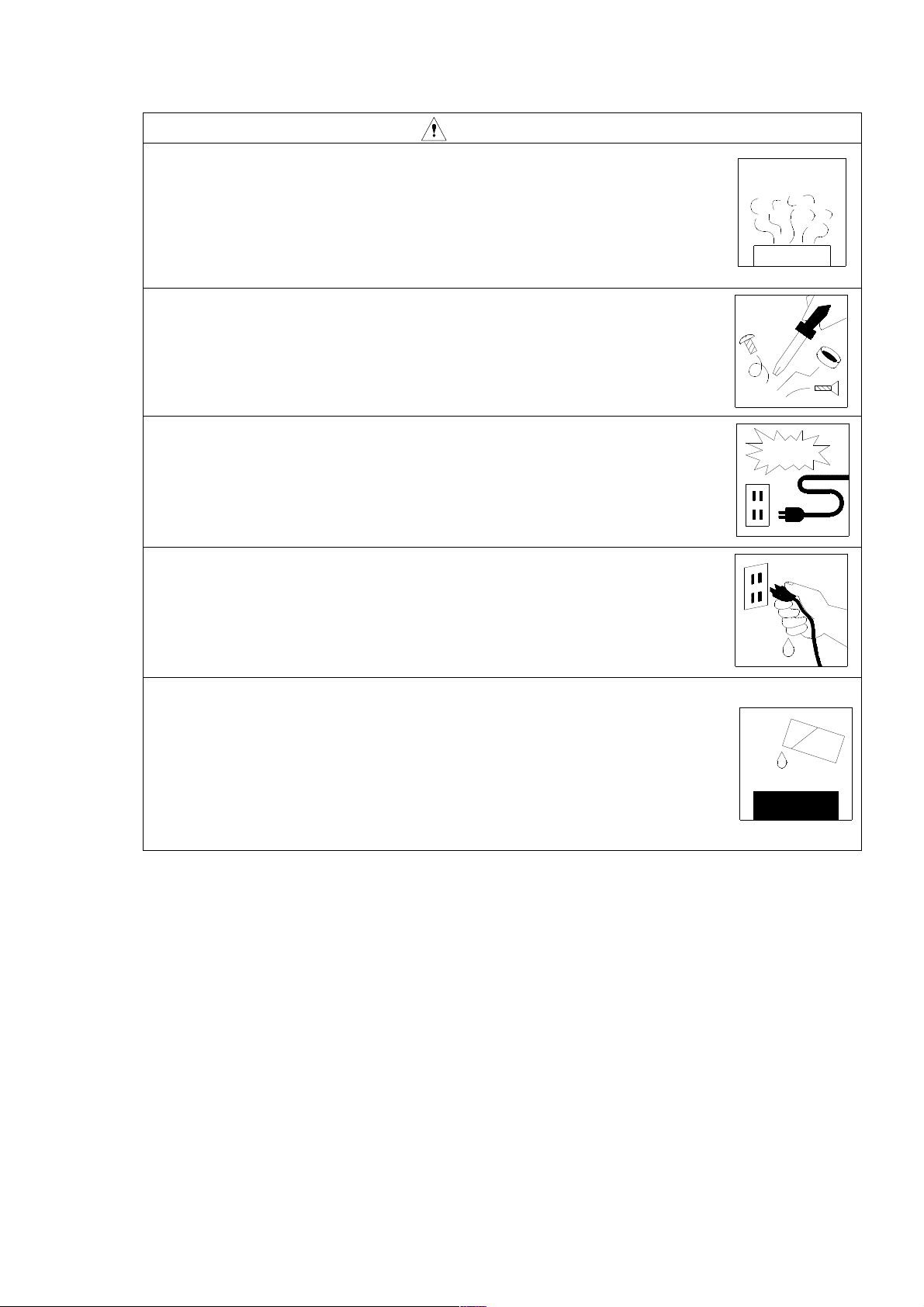
Stop using the instrument, when producing smoke, bad smell or noise.
It causes fire or shock hazard.
Turn off the POWER switch and unplug the AC adaptor (optional)
from outlet as soon as possible.
To reduce risk of injury, take it to a qualified serviceman when
service or repair is required.
Please contact us or the dealer when service or repair is required.
Do not substitute parts or modify instrument.
It causes bodily injury, fire or shock hazard.
Do not use the AC power adaptor except the optional AC-1026.
Other type of adaptor may cause damage to the instrument.
WARNING
Do not touch the plug of AC adaptorwith wet hands.
It causes shock hazard.
Stop using the instrument, when an object or liquid falls/spills into
the instrument.
It causes fire or shock hazard.
Turn off the POWER switch and unplug AC adaptor (optional)
from outlet as soon as possible.
To reduce risk of injury, take it to a qualified serviceman
when service or repair is required.
Please contact us or the dealer when service or repair is required.
Page 5
4
3333....Cautions for usage
This equipment is assembled with precision parts.
To prevent bodily injury or damage to the instrument, the following cautions must be observed.
CAUTION
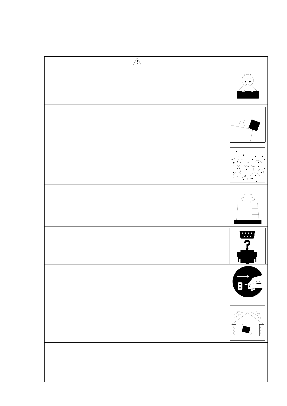
Keep the instrument away from the children.
If the instrument falls down, it is very dangerous.
Do not place it on an unstable place (shaky table or sloping place).
If the instrument falls down, it is very dangerous.
Do not expose the instrument to moisture or dust.
It causes fire or shock hazard.
Do not put heavy objects on the instrument.
It causes damage to the instrument.
Connect cable properly, it is instructed in this manual.
Wrong connection causes fire hazard.
Before you move the instrument to other place, turn off the POWER
switch and remove all wiring.
Do not put the instrument on the vibrating place.
If the instrument falls down, it is very dangerous.
For avoiding liquid spill, remove alkaline dry batteries
when you don’t use for long period of time.
It is recommended to remove alkaline dry batteries after each use.
Page 6

5
Disclaimer in usage of the software product
When this software is used, it is assumed that the customer has accepted all the following items.
1) The customer is permitted to use this software product based on the agreement of use
conditions, not to transfer or sell to the third party.
In case the customer cannot accept the following items, the product cannot be cleared to
use, either.
2) The software product, together with attached documents such as instruction manuals,
belongs to KANOMAX and is protected by the Copyright Law., etc.
The customer is not permitted either to copy, modify, alter this software product, or remove the
product label.
The customer is not permitted to create any similar products, or have the third party do
these actions.
3) Please do try hard to keep every user or users scheduled about the items above before the
use of this product.
As would be realized, the customer may be considered to have acted against the agreement
when the user of this product acted against it.
Disclaimer in usage of the SD card
(1) The folder / file in the Memory card (SD card) please do not perform a change
(addition and deletion) or a format from PC.
When I changed it, normalcy does not work.
(2) When I delete a data file in the memory card (SD card), please carry out deletion by using
the main body of MODEL 4431.
<Contents of the Memory card (SD card)>
STD・・・・・・・The folder of the data file of the normal measurement
001.csv
・
・
nnn.csv
TM5・・・・・・・Power average value of the maximum sound pressure level in a given interval
001.csv
・
・
nnn.csv
The data file
(File name:001.csv~999.csv)
The data file
(File name:001.csv~999.csv)
Page 7
6
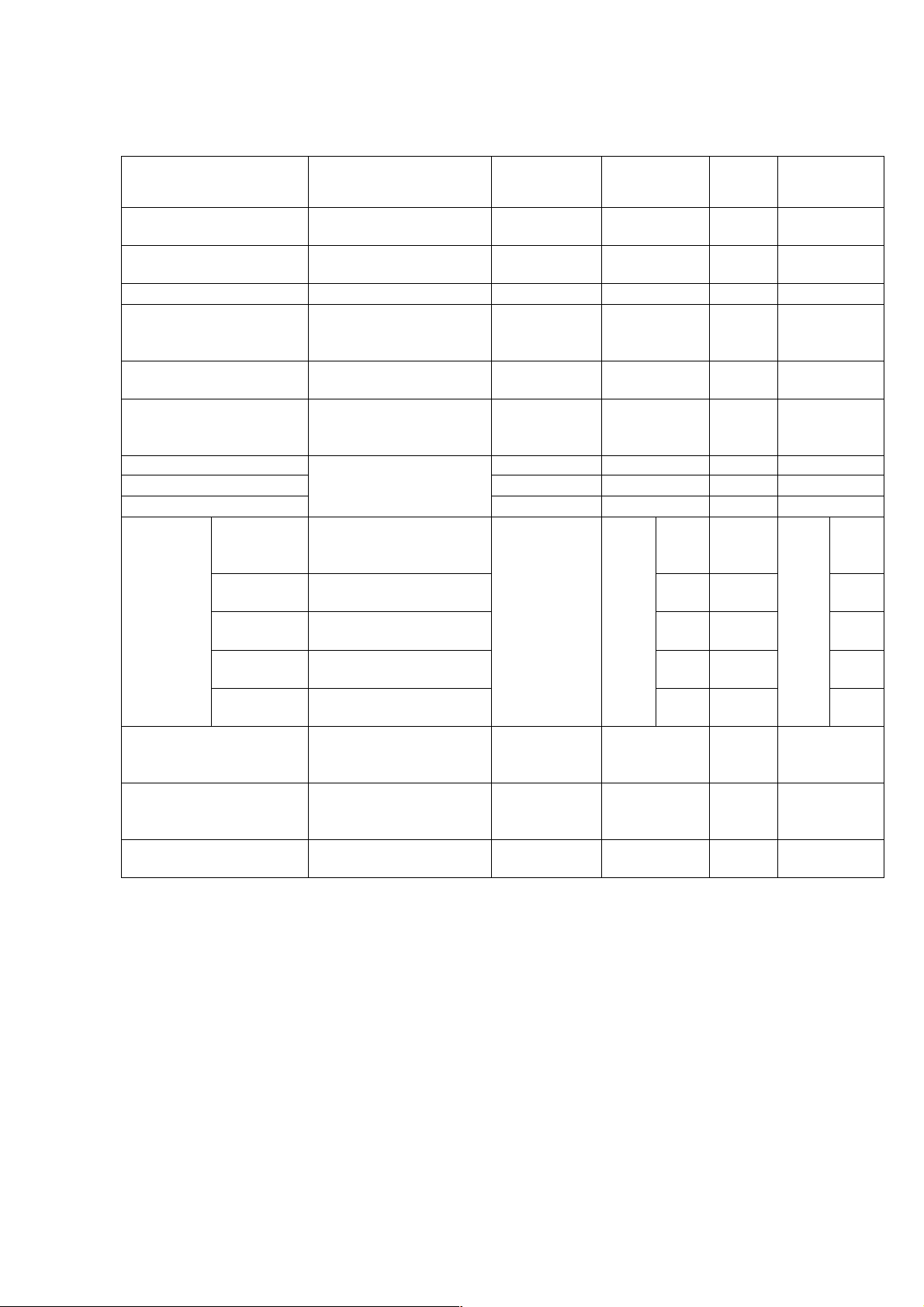
The Quantifier form of International standard and JIS (Japanese Industrial Standards).
The Quantifier is excerpted from ISO 1996、3891、IEC 60804、JIS Z 8202、8731.
Notation of
MODEL4431
Name
LA A-weighted sound
pressure level
LC C-weighted sound
pressure level
LP
L
Equivalent continuous
Aeq
Sound pressure level
A-weighted sound
pressure level
L
Equivalent continuous
Ceq
sound pressure level
Leq Equivalent continuous
sound
pressure level
LAE A-weighted LAE LAE LAE
LCE C-weighted
Sound exposure level
LE
L
5% of the percentile
A05
sound
pressure level
L
10% of the percentile
A10
sound pressure level
LAN
L
50% of the percentile
A50
sound pressure level
L
90% of the percentile
A90
sound pressure level
L
95% of the percentile
A95
sound pressure level
L
Maximum sound
Amax
pressure
level
L
Minimum sound
Amin
pressure
level
L
Peak sound pressure
Cpeak
level
Frequency
weighting
characteristics
ISO IEC JIS
A-weighted LpA
C-weighted
Z-weighted LP
A-weighted L
Aeq ,T
C-weighted
Flat
Flat
A-weighted L
AN,T
A-weighted
A-weighted
C-weighted
-
LpA
- - -
L
LP
Aeq ,T
-
-
L
L
-
Aeq ,T
Ceq, T
- - -
- - -
- - -
L
L
L
L
L
A5,T
A10,T
A50,T
A90,T
A95,T
-
-
-
-
-
L
AN,T
- - -
- - -
-
L
Cpeak
-
L
L
L
L
L
A5,T
A10,T
A50,T
A90,T
A95,T
Page 8

7
Contents
Overview
Locations and their functions 9
Front / Back / Side view of the main body 9
Operating Portion 10
Side view of the main body 11
System components 12
AC adaptor AC-1026 13
Mounting on the tripod 13
Memory Card(SD card)and program card(Option) 13
Extension Cable(BC-0046) 13
Connection with printer(BS2-80TS) 13
Level recorder (TYPE 5008A) 13
Connection with personal computer 14
Display (Explanation of measurement screen )
Measurement screen 15~16
Preparation
Battery installation 17
LCD back-light 18
LCD adjustment 19
Calendar adjustment 20
Calibration 21~22
Menu screen 23~27
Measuring Procedure
Sound pressure level(Lp)measurement : Frequency weighting key Z 28
Temporal level display of Sound pressure level(Lp)measurement 29
A-weighted sound pressure level(LA/LC):Frequency weighting key A,C 30
Time level display of A-weighted sound pressure level(LA/LC) 31
Equivalent continuous A-weighted sound pressure level(L
Single event sound exposure level(LAE)measurement 33
Maximum A-weighted sound pressure level(L
Minimum A-weighted sound pressure level(L
Amax
),
Amin
Precentile level(LAN)measurement 35
Preak sound pressure level(L
C-weighted preak sound pressure level (L
)measurement 36
peak
)measurement 37
cpeak
C-weighted equivalent continuous sound pressure level (L
Power average value of the maximum sound pressure level in a given interval(L
measurement 39
Impulse sound pressure level(LAI)measurement 40
Impulse equivalent continuous A-weighted sound pressure level (L
measurement 41
Memory function
Record of memory 【Nomal】mode, 【Auto】mode 42~45
Data recall from the memory 46
How to use the Memory card (SD Card -Standard-) 47~48
Example of file creation 49
Print/Data management
Print 50
Saveing Data to PC 51
Out put terminal 52
Specifications 53~55
Pin Connections and How to Connect the Extension cable 57~58
Communication Command 59~64
)measurement 32
Aeq
)measurement 34
)measurement 38
Ceq
)
AIeq
Atm5
8
)
Page 9

8
Overview
This specification refers to the Sound Level Meter MODEL4431.It covers most measurands
corresponding to JIS and –ISO.The 4431, provided with many functions usually mounted in
equivalent products, has been realized at an extremely low price.
Measurement of most measurands, such as Equivalent continuous A-weighted sound pressure
level (L
The 4431 was developed to keep comfortable sound environment as well as safe and healthy life
of people, both to be realized by the evaluation of environmental noise such as traffic noise or
industrial equipment noise, or by better understanding of the labor health environment at offices,
factories, etc.
The impressive design of 4431 symbolizes satisfactory operations and many performances related
to JIS and/or IEC. It sure is a highly efficient and highly reliable precision sound level meter,
to be supported by the next generation.
), Sound exposure level (LAE), A-weighted sound pressure level (LA), etc., is possible.
Aeq
Features
● Excellent cost/performance ;covers most measurands in current criteria
● The “0-dB” function 【 world first 】(option)
;measurement of the noise of ultra-low sound pressure level is possible.
The function displays the greatest force in the evaluation of “quietness” or sound
quality of silent model of recent IT/OA equipments, as well as in those of
air-conditioning noise level or sound isolation capability of newly built concert
halls where the room ambient noise is below "NC-20 .
● Percentile sound pressure level (LN) ;any 5 selectable values is available
● Measurement of Equivalent continuous A-weighted sound pressure level (L
;Measurement of environmental noise required to
secure occupational heal
● Wide linearity range of 100dB ;Covers wide range of 20~130dB
● Equipped with an USB Ver1.1 function;allows data processing for PC
● Equipped with a memory function ;realized by in built-in memory or memory card.
● Backlight LCD screen for high ;visibility and easy-on-the eye display
● Timer function ;measurement can be paused or restarted at any
point of time by installing the function.
● Abundant program cards(Option) ;1/1and 1/3-octave Real-time analysis card, FTT
analysis Card, RSR card (Real sound recording Card), etc.
Aeq
)
Configuration
1)Sound Level Meter MODEL4431 1
2)Memory Card ( SD Card ) 1
3)Windscreen(φ50) 1
4)Batteries LR6 4
5)Screwdriver 1
6)Hand strap 1
7)Instruction manual 1
8)Carrying case 1
9)Option
・1/1 and 1/3-octave Real-time Analysis Card NA-0038
・FFT Analysis Card NA-0038F
・RSR Card ( Real Sound Recording Card ) NA-0038R
・Data management software NA-0038M
・0-dB function (0~80dB(A)) 4431(0dB)
・AC adapter AC-1026
・Output cable(BNC pin cord) BC-0071
・USB interface cable BC-0038PC
・Extension cable(2m~30m) BC-0046-2~30
・Tripod exclusively for sound level meter NA-0333
・Sound calibrator TYPE2127
Page 10
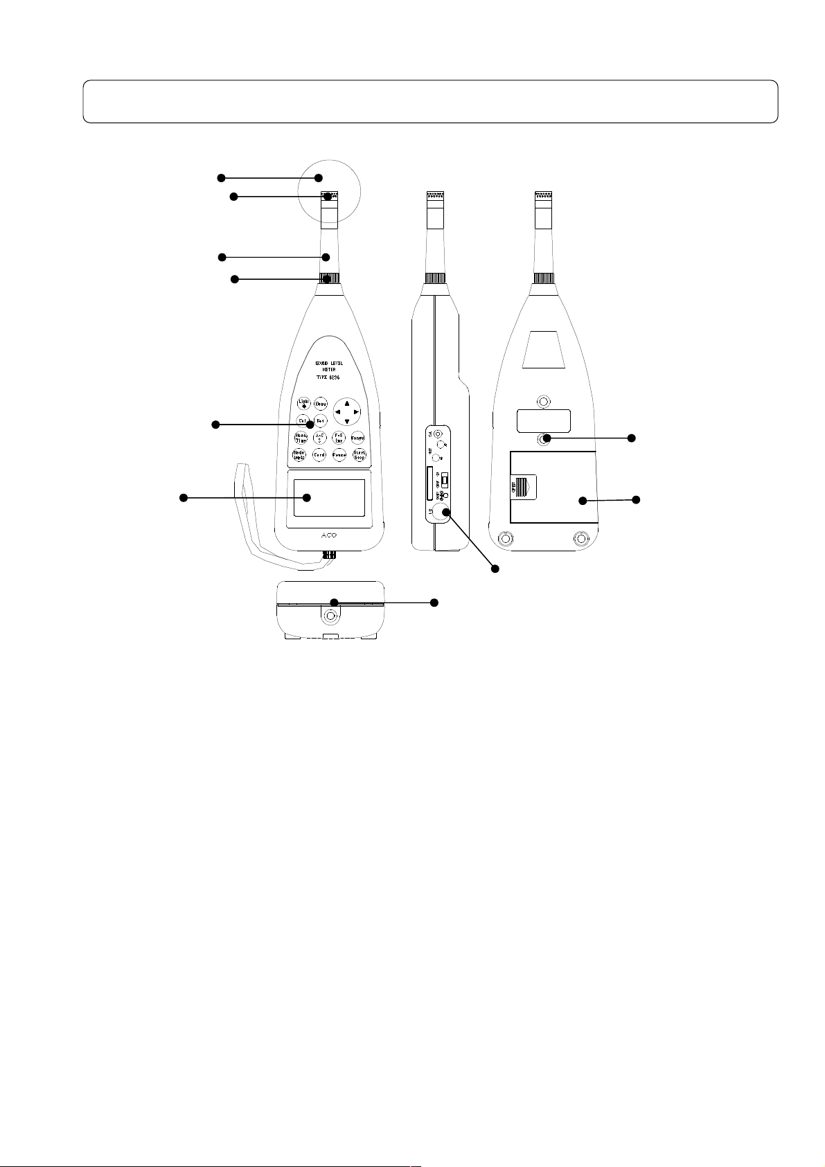
9
Locations and their functions
Front/Back/Side view of the main body:
Wind screen(φ50)
Microphone
Preamplifier
Threaded
retaining ring
Front panel
Display
Side panel
Female screw for tripod
Front
Microphone Preamplifier
The microphone and the preamplifier are comprised as one body.
They can be placed apart from the main body and connected to it with the optional
extension cable
Display
It is a liquid crystal display with backlight. The sound level is displayed here with
numerical value or bar graph. The operation condition of the sound level meter, setting
condition of the measurement mode, various alerts, etc. are also displayed.
Windscreen(φφφφ50)
The measurement error may be caused in the windy outdoor site or noise measurement of
ventilator, since the wind drives against the microphone generating the wind noise.
Under such conditions, it is possible to reduce the wind noise by attaching the φ50
windscreen to the microphone
Strap
Used to prevent unexpected drop of the main body. Please put it through your wrist when
you measure with the body in hand.
Back
Female screw for tripod
It is possible to mount the main body to this tripod for the camera with screw.
Batteries case
Put four LR6 type Alkali dry batteries.
Female screw
for tripod
Battery cover
Page 11
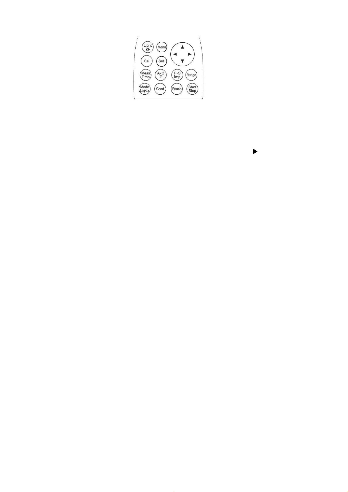
10
Operating Portion
Light key
The backlight illuminates the display in darkness, which goes out automatically 30
seconds later or by pushing the key again.
Menu key
It is pushed to set up the measurement condition, when the display is adjusted to 1/3
page of the menu panel.
The item is selected with cursor key ▲▼, and input starts with , as well as the
alteration with ▲▼. To go back to the measurement setting screen, push [SET] key
again.
Cal key
When the calibration or level setting with the equipment connected, this key is used.
Set key
The key to be used to fix the input.
Meas. Time key
The key to set the measurement period (interval time terminated with a pair of Star/Stop).
It changes on pushing the key as: key is pushed again.
1s, 3s, 5s, 10s, 1m, 5m, 10m, 15m, 30m, and 1h, 8h, 12h, 24h, and *** (Forever: Until
Stop).
A・・・・C,,,,Z key
The key to select frequency weighting A, C, and Z (FLAT)
F・・・・S,,,,Imp key
The key to select time-weighting Fast, Slow, and Imp
Range key
Range setting key which enables the following 6 ranges:
20~80、20~90、20~100、20~110、30~120、40~130
Mode Leq ・・・・Lx key
The key to display the calculation results. Each push gives various calculation results
selected on the Menu screen.
Card key
The key to use various option cards
Pause key
By pushing the key, the measurement is paused to eliminate any unexpected noise or
anomaly during the measurement. It is resumed by pushing the key again. By using
the data elimination function, it is possible to exclude the data 3 or 5 seconds before the
key is pushed.
Start////Stop key
The key to start the measurement of various mode or to terminate it.
Page 12
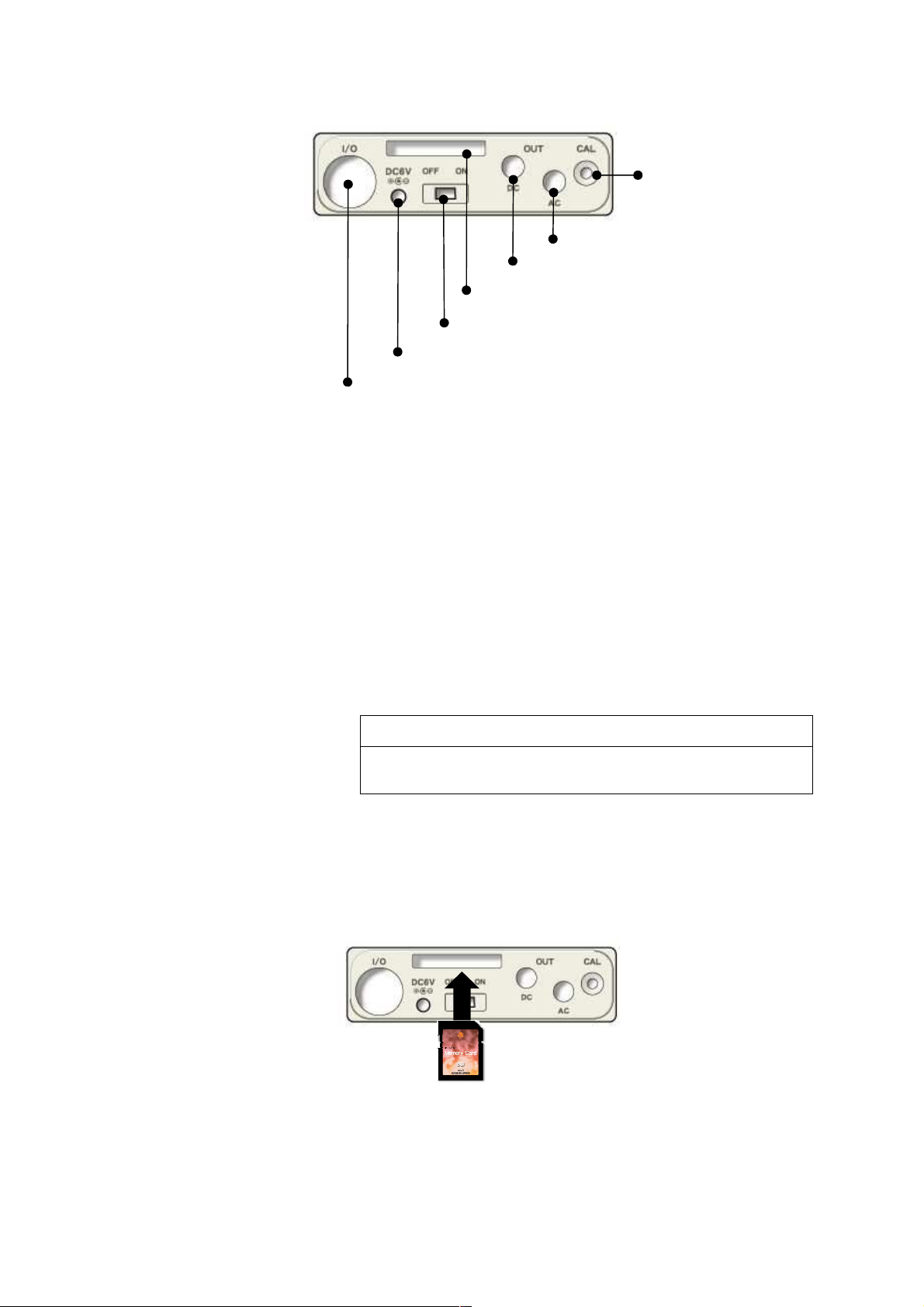
11
Side view of the main body
AC power adaptor connector
By using the optional AC adaptor, AC100V is available for the measurement.
Please do not use any other power supplyies than specified AC adaptor. It may cause
breakdown or malfunction.
AC////DC out connector
AC: outputs frequency-weighted AC signal.
DC: outputs DC level signal .
External Input/Output connector
Input or output terminal for control signal or measurement data, which can be connected
to a printer, level recorder, or personal computer.
Card slot
The slot for memory card or optional program card.
Side panel
AC power adaptor connector
External Input/Output connector
Calibration potentiometer
AC OUT connector
DC OUT connector
Card slot
POWER switch
NOTE
・ Please watch out for the card slot portion when you
have it in hand. The card may jump out.
Inserting and detaching the card
1. Insert the card into the card slot on the side panel.
Press softly the card into the slot until it comes to the end, watching for the direction of the
card.
2. Press the card again for detaching it. The card comes off by itself.
Page 13
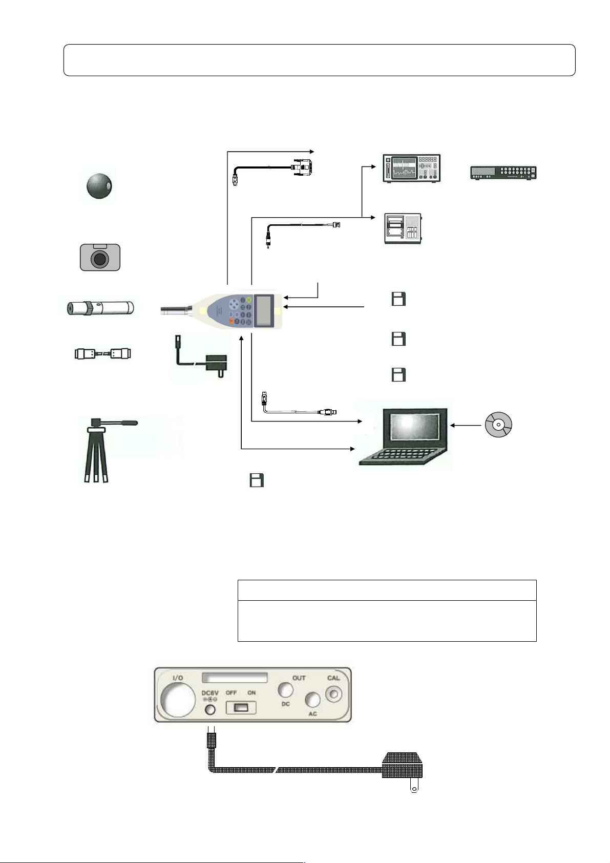
12
System configuation
Example of system configuration
※The function can be extended by the connecting various option measuring instruments.
Windscreen(φ90)
NA-0301
Sound Calibrator
TYPE 2127
Sound Level Meter
TYPE6236/6238
RS-232C
interface cable
BC-0026PC
BNC pin cord
BC-0071
0-dB function[0~80dB(A)]
Printer
BS2-80TS
Piston phone
TYPE 2124A
Extension cable for
microphone
BC-0046
AC adapter
AC-1026
USB interface cable
BC-0038PC
Tripod exclusively
for sound level meter
NA-0333
Memory Card(SD Card)
AC adaptor (option)
1) Turn off the power switch.
2) Connect the option AC adaptor to the AC adaptor terminal.
3) Insert the AC plug of the AC adaptor to the AC100V outlet.
Oscilloscope
Data recorder
Level recorder
TYPE5008A
Program cards ( SD Card )
1/1 and 1/3-octave Real-time Analysis Card
NA-0038
FFT Analysis Card
NA-0038F
Real Sound Monitor Card
NA-0038R
PC
Data management software
NA-0038M
NOTE
Please do not use any other power supplies than
specified AC adaptor. It may cause breakdown or
malfunction.
AC power adaptor
connector
AC adaptor
to AC100V outlet
Page 14
13
Mounting on the tripod
It is possible to mount this equipment on the camera tripod in lengthy measurement.
Please be careful enough not to drop the equipment or fell the tripod
Memory card (SD card) and program card (Option)
The measurement results can be stored in Memory card (SD card) to reedit it on personal
computer
Moreover, option program cards enable to set up the conditions of 1/1 or 1/3 octave filter card,
FFT analysis card, and RSR card (Real sound recording card)
Extension cable (BC-0046)
Please make sure to switch off the power when connecting or disconnecting the microphone
extension cable.
To avoid the influence of diffraction effect of the sound level meter body, or of the existence of
the measuring person, microphone can be placed away from the main body.
Please refer to “Pin Connections and How to Connect Extension cable” in P51 for further
information.
NOTE
Never separate the microphone from the preamplifier,
which may cause breakdown or malfunction
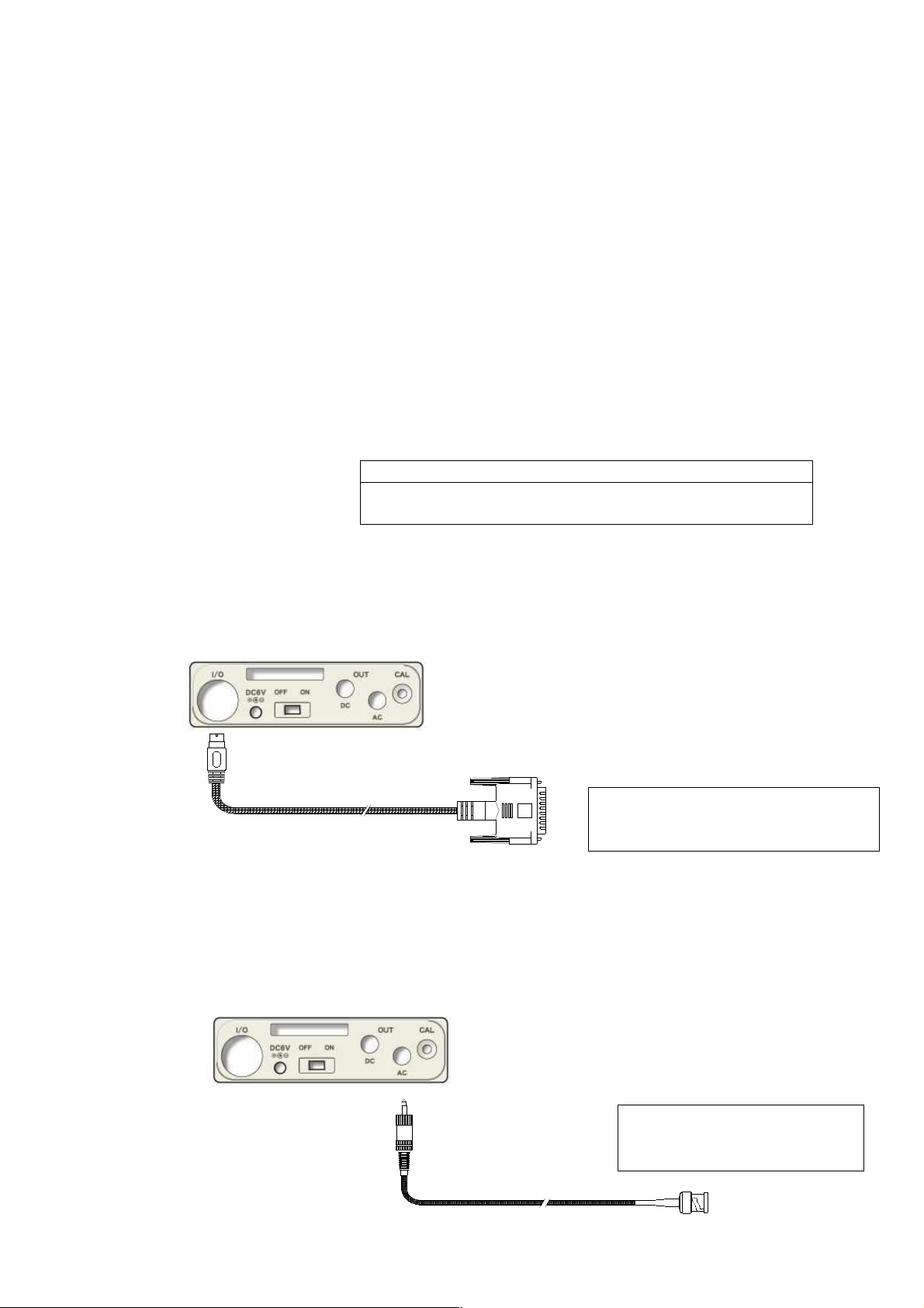
Connection with printer ((((BS2-80TS))))
Connect the serial input terminal of printer (BS2-80TS) to I/O terminal on the side panel with
RS-232C interface cable (BC-0026PC). (both available as option).
I/O terminal
Printer cable
To printer
To serial input terminal
Level recorder (TYPE 5008A)
How to record the sound pressure level
Connect AC output connector on the side panel to level recorder with output cable
(BC-0071 : Option) as shown in the following figure.
AC output connector
To input terminal of the
level recorder
Output cable
Page 15
14
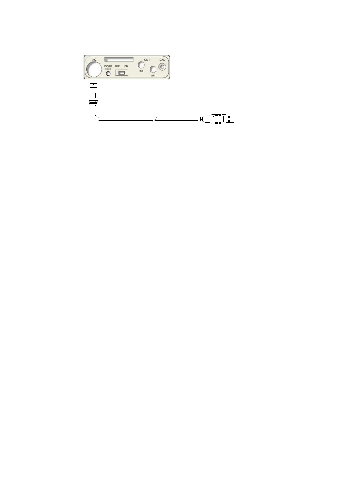
Connection with personal computer
External connect I/O on the side panel to USB terminal of personal computer with the option
interface cable.
External I/O
connector
USB cable
To USB terminal of
personal computer
Page 16
15
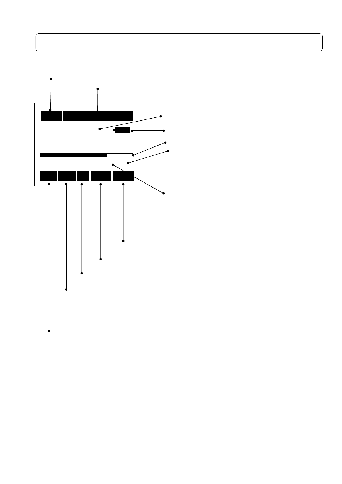
Display (Explanation of measurement screen)
Measurement screen
Measurement time
Displays the elapsed time of the measurement
With [Start/Stop] key entry, time count operation is carried
10
10mmmm
1010
99
99hhhh60
9999
94.0
94.0
94.094.0
40 Cal 130
40 Cal 130
40 Cal 13040 Cal 130
Rec Un A Fast Leq
Rec Un A Fast Leq
Rec Un A Fast LeqRec Un A Fast Leq
Displayed when the measured value exceeds the range selected, as well as Un
when the input l level is lower than the selected range.
Ov : Over ;+3dB from upper limited scale
Un : Under ;-0.6dB from lower limited scale
Displays operation condition y
Rec blinking: Under the measurement started with [Start/Stop] key pushed.
Stp blinking: Measurement terminated
Measurement time
The measurement time is displayed, which is one of the following :.
1s、3s、5s、10s、1m、5m、10m、15m、30m、1h、8h、12h、24h、***(Forever: Until
[Start/Stop] key entry)
Pause (Temporary interruption mark)
Blinks when the calculation or data saving to memory is canceled, where displayed level
is not updated
60mmmm60
6060
60ssss
6060
dB
Fast: Time weighting characteristics: Displays the dynamic
characteristics selected with [F・・・・S Imp] key. (Fast, Slow or Impulse)
A: Frequency weighting characteristics: Displays the frequency
weighting selected with [A,C,Z] key.
[Freq Corr] button. (A, C, Z)
out until completion of the measurement time.
Display data: Displays the current value
numerically.
Remaining capacity of battery.
Bar: Displays the current instantaneous level.
Display Range: Displays upper and lower limit of
the bar graph displayed Displays the upper and
lower limit of the range for bar graph to be
displayed, selected according to the magnitude of
sound level.
Cal、、、、Pause、、、、Card:Displays calibration, pause, and
card insertion, respectively. Displays “Calibration”
with [Cal] key, Pause with Pause key, and Card
with card inserted, respectively.
Leq:Measurement mode. Displays the mode selected with
[Mode] key. (Lp, Leq, Lmax・・・・・・・
・・・・・・・)
・・・・・・・・・・・・・・
Page 17
16
20
2020
20
80
8080
80
80dB
dB
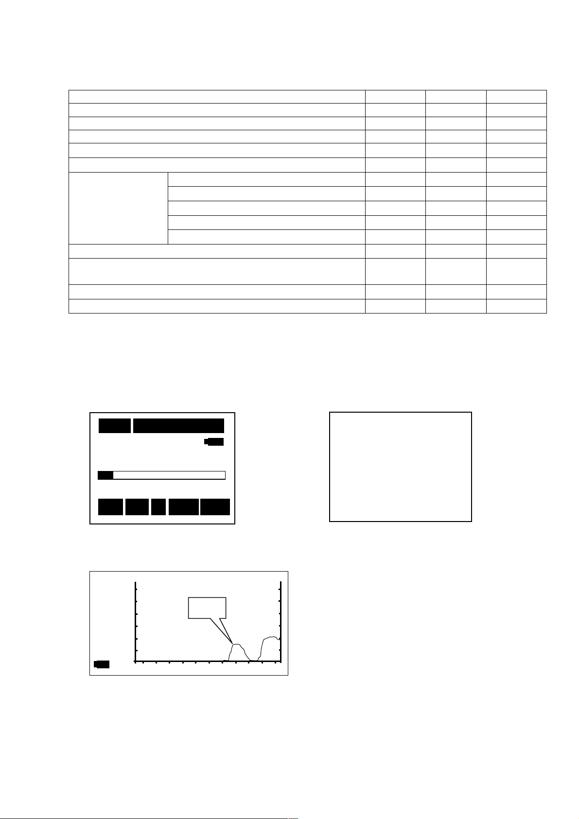
Frequency characterisitic and Calculation function
Style A C Z
Sound pressure level LA LC Lp
Equivalent continuous sound pressure level L
Sound exposure level LAE LCE LE
Maximum sound pressure level
Minimum sound pressure level
Percentile (5%) sound pressure level
Percentile sound
pressure level
(LAN)
Peak sound pressure level
Power average of maximum sound pressure level in a
given interval
Impulse sound pressure level
Impulse equivalent continuous sound pressure level
Display example
<Measurement screen>
Percentile (10%) sound pressure level
Percentile (50%) sound pressure level
Percentile (90%) sound pressure level
Percentile (95%) sound pressure level
<Menu screen>
L
L
L
L
L
L
L
L
L
Aeq
Amax
Amin
A05
A10
A50
A90
A95
―
Atm5
LAI
AIeq
L
L
Leq
Ceq
― ―
― ―
― ―
― ―
― ―
― ―
― ―
L
Cpeak
― ―
― ―
― ―
peak
10
10mmmm 000
1010
000hhhh00
000000
38.6
38.6 dB
38.6 38.6
00mmmm05
0000
05ssss
0505
dB
dBdB
Stp
Stp A
<Example of T-L (time level) display>
StpStp
38.6
Fast
Lp
A Fast Lp
A A
20
Fast Lp
Fast Lp Fast Lp
Data
<System>
<System>
<System><System>
Mode
Mode ::::Norma
ModeMode
Data delet
Data delet ::::off
Data deletData delet
LCD cont
LCD cont :***
LCD contLCD cont
Date
Date y/m/d
y/m/d ::::01/01/01
DateDate
y/m/d y/m/d
Tim
Time h/m/s
e h/m/s ::::00000:00:00
TimTim
e h/m/se h/m/s
Printer(pc)set
Printer(pc)set::::9600
Printer(pc)setPrinter(pc)set
USB out
USB out ::::OFF
USB out USB out
1/3
Normal
NormaNorma
off
offoff
:***
:***:***
01/01/01
01/01/0101/01/01
0:00:00
0:00:000:00:00
9600
96009600
OFF
OFFOFF
1/3
1/31/3
l
l l
Page 18
17
Preparation
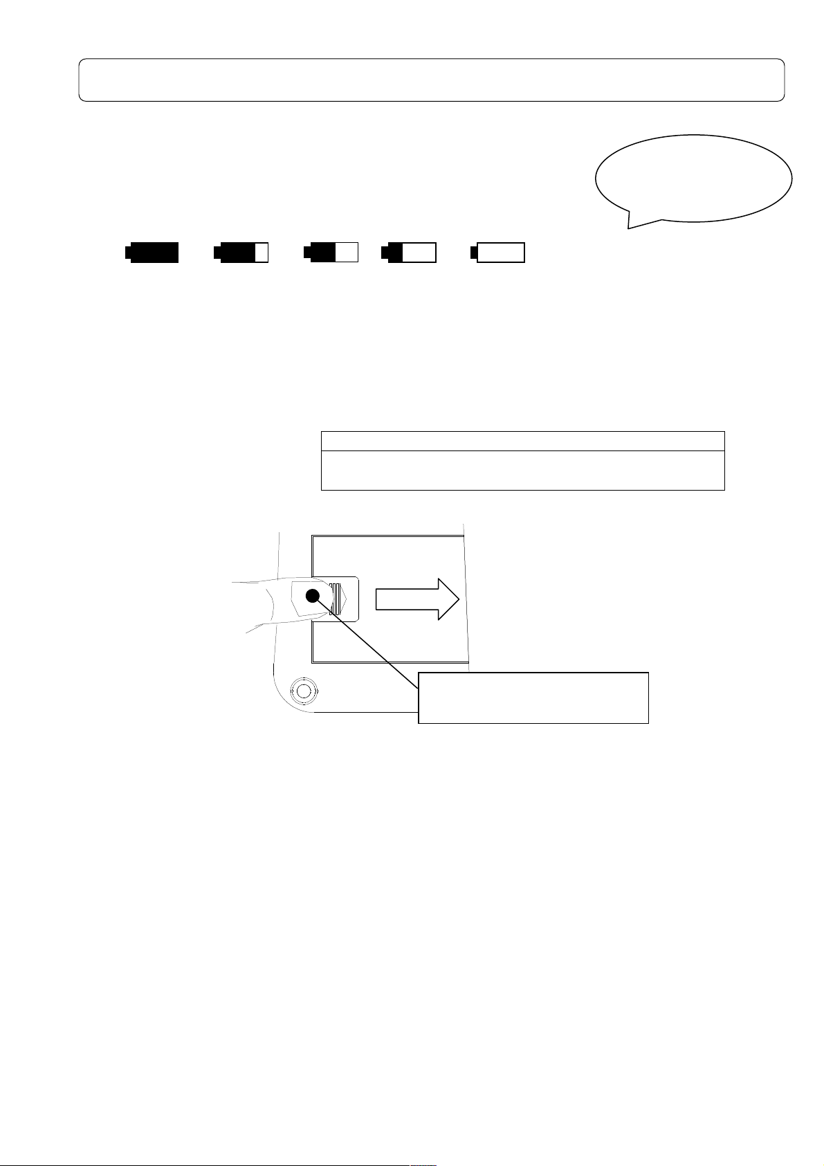
It will blink,
Battery installation
When LCD display tells low battery, install new batteries.
For long-term measurement, install new batteries in advance.
The following displays tell you the condition of the batteries.
The battery residual quantity display are the 5 stages like the following.
FULL
LOW
EMPTY
Replace batteries
To install new batteries:
1) Turn off the POWER switch.
2) The slide is done while pushing the battery lid by the thumb.( Refer to the figure below).
3) Put the new batteries in the case, then shut the cover. The inside of the case shows you the
direction of the batteries.
NOTE
Do not put the batteries in the wrong direction. These
four batteries should be replaced at the same time.
“OPEN” pushing and slide in
the direction of the arrow.
・Battery life is approximately:
9 hours (Alkaline batteries, continuous operation)
・Use of LCD back-light shortens the life of the batteries (approximately 1/3).
・Please prepare the AC adaptor AC-1026(option) in advance when it is used for a long
period of time.
if"ENPTY" is displayed,
and a power supply is
shut off.
Page 19
18
LCD back-light
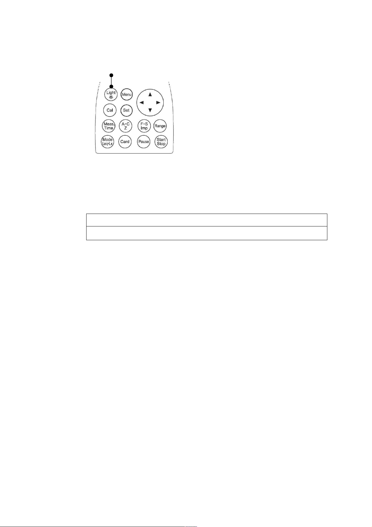
You can use LCD back-light, when your measurement is carried out in the dark situations.
[Light] key
1) Press [Light] key, LCD back-light goes on.
2) If you press [Light] key again, LCD back-light goes out.
The light automatically goes out in about 30 seconds after the light goes on.
3) When the batteries is low, LCD back-light dims.
NOTE
Use of LCD back-light shortens the life of the batteries.
Page 20
19
LCD adjustment
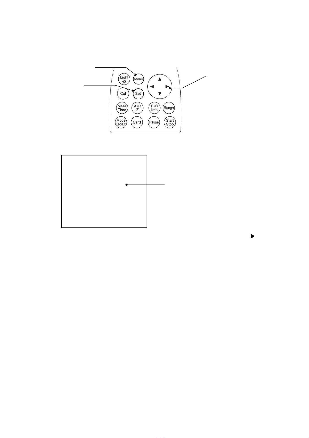
You can adjust LCD contrast, when the batteries were low, or when the new batteries were
installed.
The procedure is as follows.
1) When you press the [Menu] key, the following screen appears.
2) Select LCD cont with Cursor key ▼, then move the cursor rightward with key.
3)Adjust the LCD contrast with ▲▼ key, then press [Set] key to save the setting.
After pressing [Set] key, the cursor moves to leftward.
4)If you want to go back to measurement mode, press [Set] key.
[Menu] key
[Set] key
<System>
<System>
<System><System>
Mode
Mode ::::Normal
ModeMode
Data delet
Data delet ::::off
Data deletData delet
LCD cont
LCD cont :***
LCD contLCD cont
Date
Date y/m/d
y/m/d ::::00/00/00
DateDate
y/m/d y/m/d
Time
Time h/m/s
h/m/s ::::00:00:00
TimeTime
h/m/s h/m/s
Printer(pc)set
Printer(pc)set ::::9600
Printer(pc)set Printer(pc)set
USB out
USB out ::::OFF
USB out USB out
Normal
Normal Normal
off
offoff
:***
:***:***
00/00/00
00/00/0000/00/00
00:00:00
00:00:0000:00:00
9600
96009600
OFF
OFFOFF
1/3
1/3
1/31/3
Cursol key
LCD adjustment
Page 21
20
Calendar adjustment
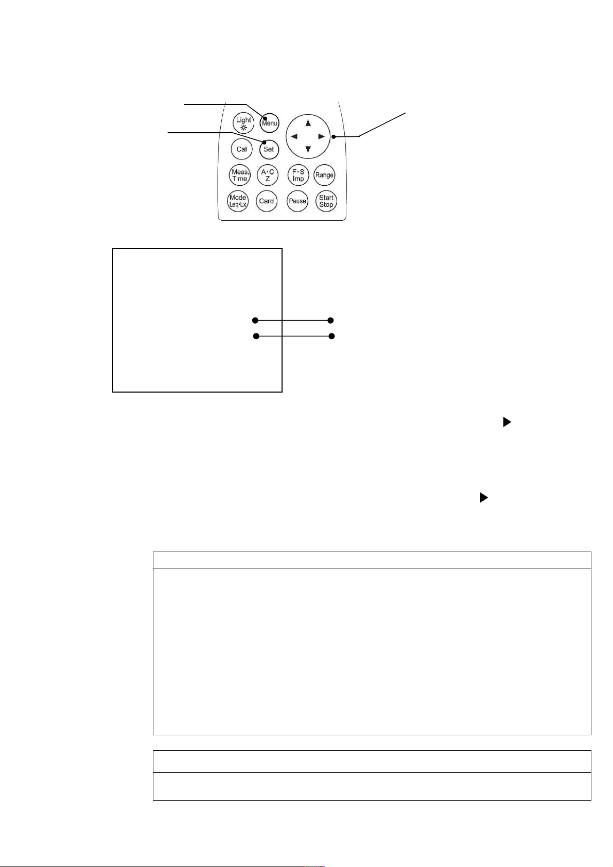
To adjust the calendar (time), operate as follows.
You can adjust calendar in the Menu mode in the same way as LCD adjustment.
When you press the [Menu] key, the following screen appears
【Calendar adjustment】
1) Select date y/m/d with Cursor key ▼, then move the cursor rightward with key.
2)Set the year/month/day with ▲▼ key, then press [Set] key to save the setting.
After pressing [Set] key, the cursor moves to leftward.
【Time adjustment】
1) Select time with Cursor key ▼, then move the cursor rightward with key.
2)Set the hour:minute:second with ▲▼ key, then press [Set] key to save the setting.
After pressing [Set] key, the cursor moves leftward.
3)If you want to go back to the measurement mode, press [Set] key.
[Menu] key
[Set] key
<System>
<System>
<System><System>
Mode
Mode ::::Normal
ModeMode
Data delet
Data delet ::::off
Data deletData delet
LCD cont
LCD cont :***
LCD contLCD cont
Date
Date y/m/d
y/m/d ::::00/00/00
DateDate
y/m/d y/m/d
Time
Time h/m/s
TimeTime
Printer(pc)set
Printer(pc)set ::::9600
Printer(pc)set Printer(pc)set
USB out
USB out ::::OFF
USB out USB out
1. If you want to go back to the measurement mode, press [Set]key.
h/m/s ::::00:00:00
h/m/sh/m/s
Be sure to enter the date (date y/m/d) in the order of “year → month → day.”
Input any figure of; y(year): 00 – 99, m(month):01 – 12, and d(day): 01 – 31.
Ex.) For November 30, 2003
Correct) 03/11/30
Incorrect) 11/30/03 30 has been entered for m(month). Input any figure of
Be sure to enter the time in the order of “hour → minute → second.”
Input any figure of; h(hour): 00 – 24, m(minute): 00 – 59, s (second) 00 – 59.
Ex.) For 23:58:32
Correct) 23/58/32
Incorrect) 32/58/23 32 has been entered for h(hour). Input any figure of
Normal
Normal Normal
off
offoff
:***
:***:***
00/00/00
00/00/0000/00/00
00:00:00
00:00:0000:00:00
9600
96009600
OFF
OFFOFF
1/3
1/3
1/31/3
01 through 12.
00 through 24.
Date adjustment
Time adjustment
NOTE
Cursor key
NOTE
You are recommended to set the built-in IC timer right before measurement,
since it could show the wrong time.
Page 22
21
Calibration
94
9494
94
....
0000
dB
dBdB
dB
You need to calibrate the instrument regularly before you start taking measurements.
There are two types of calibration. One is the way using the internal generator, the other is the way
using the pistonphone. Note that calibration is disabled when “Peak measurement” is selected
Calibration using internal generator
You can calibrate the instrument using the internal generator (1kHz, sine wave)
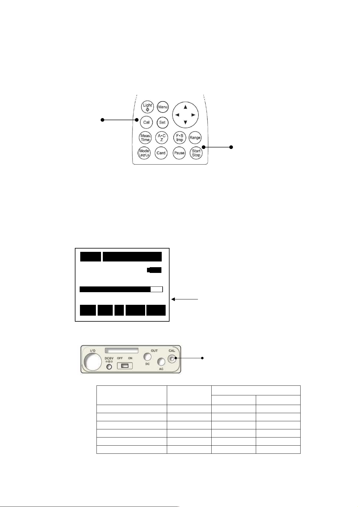
[Cal] key
[Range] key
1) Turn on the POWER.
2) Press [Cal] key.
3) Press [Range] key, and choose ‘100dB’ by cursor keys ▲▼, and press [Range] key again to
register.
4) Adjust the calibration potentiometer on the side panel until the display shows 94dB.
5) If [Cal] key is pressed once again, the calibration is completed.
<<<< Calibration display >>>>
<<<< Side panel >>>>
<<<< Reference>>>> Full scale range and Cal(the display shows)
10
10mmmm
000
1010
20
20
2020
Stp
Stp
StpStp
000hhhh00
000000
Cal
AAAA Fast
00mmmm05
05ssss
0000
0505
Cal 100
Cal Cal
Fast L
Fast Fast
Full scale range
(dB)
80 74.0 0.500 2,350
90 84.0 0.500 2,350
100 94.0 0.500 2,350
110 104.0 0.500 2,350
120 114.0 0.500 2,350
130 124.0 0.500 2,350
100
100100
LA
LL
Cal flashes on and off
A
AA
Calibration potentiometer
CAL
(dB)
OUTPUT(V)
AC OUT DC OUT
Page 23
22
Pistonphone ( MODEL 2124 A) or Calibration using Sound Calibrator ( MODEL 2127 )
Lp
LpLp
Lp
LLLL
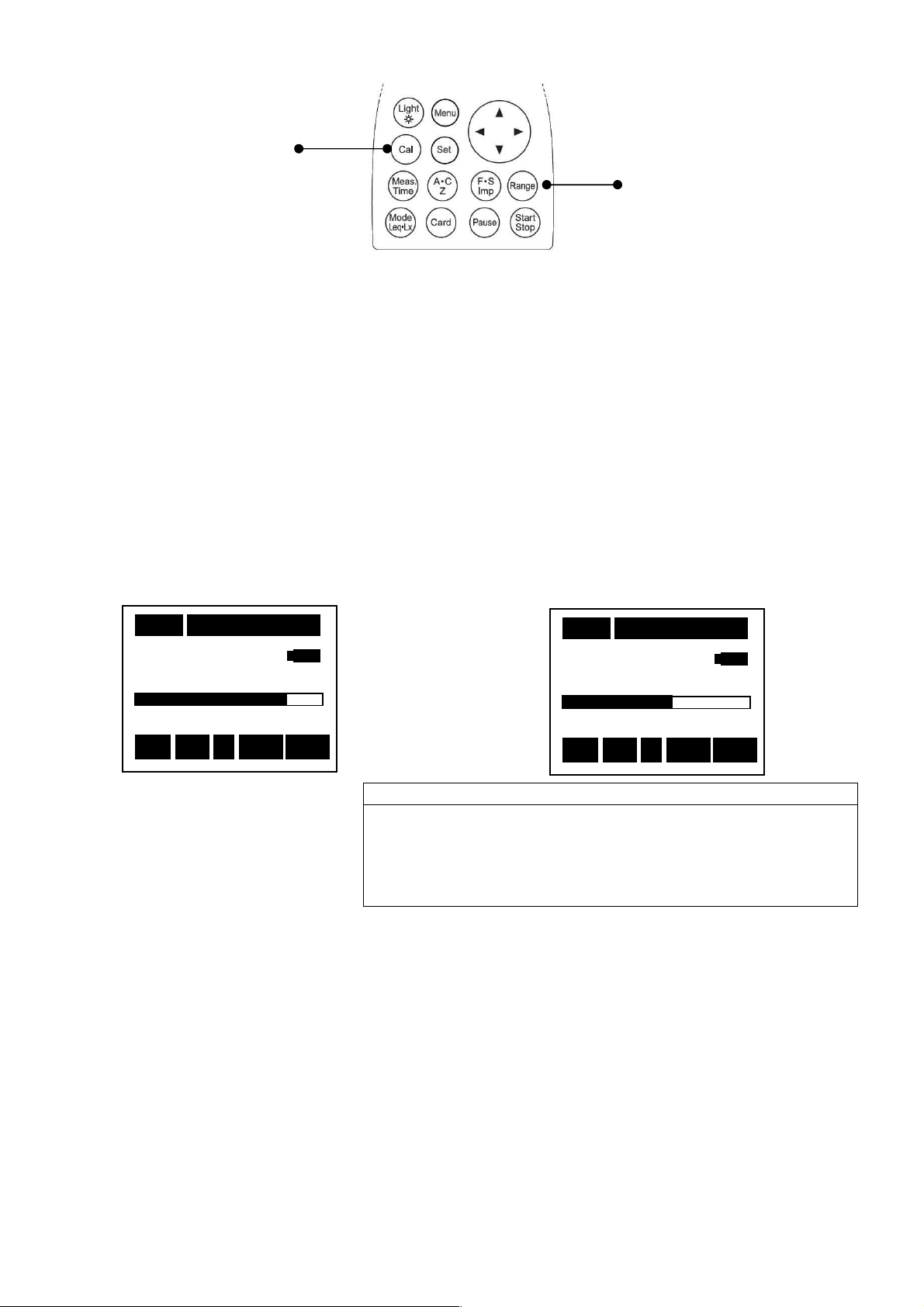
1) Turn off the POWER of Pistonphone (MODEL 2124A) or Sound Calibrator (MODEL 2127).
2) Turn on the POWER of this equipment
3) For the Pistonphone, Set the frequency weighting to Z with Frequency weighting key, set
the time weighting to Fast with Time weighting key and set the range to 40~130dB with
[Range] key.
For the Sound Calibrator, Set the frequency weighting to Z with Frequency weighting key,
set the time weighting to Fast with Time weighting key and set the range to 20~100dB
with [Range] key.
4) Insert microphone of this equipment to Pistonphone ( MODEL 2124A ) or Sound Calibrator
( MODEL 2127 ).
5) Switch on the Pistonphone ( MODEL 2124A ) or Sound Calibrator ( MODEL 2127 ).
6) Adjust the calibration potentiometer on the side panel until the display shows a output
level of the pistonphone (standard value is 124dB) and a output level of the sound
Calibration (standard value is 94dB).
<<<<Pistonphone in use>>>> <<<< Sound Calibrator in use >>>>
1111ssss
124
124....0
124124
40
40
4040
Stp
Stp ZZZZ Fast
StpStp
CAL key
000
000hhhh00
000000
00mmmm00
00ssss
0000
0000
0 d
00
dddBBB
130
Fast
Fast Fast
B
130
130130
Range key
1111ssss
000
000hhhh00
00mmmm00
000000
99994444....0
22220000
Fast
AAAA
Insertion and extraction of the microphone to/from the
sound calibrator should be made slowly and softly. Rapid
insertion and extraction may cause strong force to the
diaphragm of the microphone due the air pressure change,
which may then give a severe damage to the microphone.
Stp
Stp
StpStp
NOTE
00ssss
0000
0000
0 d
00
1
Fast
Fast Fast
B
dddBBB
1110000000
0
AAAA
Page 24
23
Menu screen
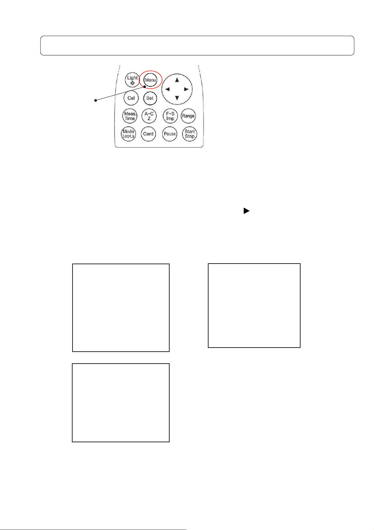
<System>1/3 → <Memory> 2/3 → <View Mode> 3/3 → <System> 1/3 → <Memory> 2/3 ・・・
Menu key
With [Menu] key pressed, the following Menu screen appears. (Under the situation with
[Start/Stop] key not pressed).
・・・
・・・・・・
Each [Menu] key pressed, you can select one of three screens as above, and return to the
measurement setting screen. .
Select an item with cursor keys ▲ ▼, start the input with , and fix the change with [Set]
key. Move to the item to change and return to the measurement
setting screen with [Set] key again.
In the use of option card (filter card), additional setting screen appears.
Please refer to the manual of each option card for the details .
<Memory>
<Memory>
<System>
<System>
<System><System>
Mode
Mode ::::Normal
ModeMode
Data delet
Data delet ::::off
Data deletData delet
LCD c
LCD cont
ont :***
LCD cLCD c
ontont
DDDDate
ate y/m/d
y/m/d ::::01/01/01
ateate
y/m/d y/m/d
Time
Time h/m/s
h/m/s ::::00:00:00
TimeTime
h/m/s h/m/s
Printer(pc)set
Printer(pc)set ::::9600
Printer(pc)set Printer(pc)set
USB out
USB out ::::OFF
USB out USB out
<View Mode>
<View Mode>
<View Mode><View Mode>
Lp
Lp ::::INST
Lp Lp
(A)View
(A)View LA05
(A)View (A)View
LAeq
LAeq ::::ON
LAeq LAeq
LAE
LAE ::::OFF LA50
LAE LAE
LLLLAAAAmin
LLLLAAAAmax
Each change made with various key operations are registered and reproduced on next
Power ON operation.
INST
INST INST
ON LA10
ON ON
OFF LA50 ::::OFF
OFF LA50 OFF LA50
min::::ON
ON LA90
minmin
ON ON
max::::ON
ON LA95
maxmax
ONON
1/3
Normal
Normal Normal
off
offoff
:***
:***:***
01/01/01
01/01/0101/01/01
00:00:00
00:00:0000:00:00
9600
96009600
OFF
OFFOFF
3/3
LA05 ::::OFF
LA05 LA05
LA10 ::::OFF
LA10 LA10
LA90 ::::OFF
LA90 LA90
LA95 ::::OFF
LA95 LA95
1/3
1/31/3
3/3
3/33/3
OFF
OFFOFF
OFF
OFFOFF
OFF
OFFOFF
OFF
OFFOFF
OFF
OFF OFF
<Memory><Memory>
Mode
Mode ::::Normal
ModeMode
Interval
Interval ::::Single
IntervalInterval
2/3
Normal
Normal Normal
Single
SingleSingle
2/3
2/32/3
Page 25

24
<System> (1/3)
<System>
<System>
<System><System>
Mode
Mode ::::Normal
ModeMode
Data delet
Data delet ::::off
Data deletData delet
LCD cont
LCD cont :***
LCD contLCD cont
Date
Date y/m/d
y/m/d ::::01/01/01
DateDate
y/m/d y/m/d
Time
Time h/m/s
h/m/s ::::00:00:00
TimeTime
h/m/s h/m/s
Printer(pc)set
Printer(pc)set::::9600
Printer(pc)setPrinter(pc)set
USB out
USB out ::::OFF
USB out USB out
1/3
Normal
NormalNormal
off
offoff
:***
:***:***
01/01/01
01/01/0101/01/01
00:00:00
00:00:0000:00:00
9600
96009600
OFF
OFFOFF
1/3
1/31/3
Item Default Contents
● Meas Mode :Normal :Normal :Normal measurement
Print :Print
PC out :Data management
Memory Call :Display recorded data
L
:Tact-max sound pressure level (STD card)
Atm5
Remote U :Communicate mode(USB)
Remote R :Communicate mode(RS-232C)
● Data delet :Off :Data deletion mode setting
Off :Date deletion is disabled
Fixed to OFF in Peak mode
3sec :Data in past 3 sec is deleted when [Pause] key is
pressed during the measurement.
5sec :Data in past 5 sec is deleted when [Pause] key
is pressed during the measurement .
※The function is disabled for Meas Time 1, 3 or 5 sec,.
● LCD cont : ***** :Adjustment of LCD contrast
See “LCD adjustment” section for the details.
● Date y/m/d :00/01/01 :Calendar setting (date: 2000/01/01)
See “Calendar adjustment” for the details.
● Time h/m/s : 00:00:00 :Time setting
See the “Calendar adjustment” for the details.
● Printer(PC) set : 9600 :Baud rate setting
USB Communicate:9600、19200
RS-232C Communicate(remote communication)
:9600、19200、38400
RS-232C Communicate
(When automatic power supply ON measurement starts)
:4800、9600、38400
● USB out :Digital data output setting
OFF → Lp → LpB → Wave
(Outputs data from USB out in parallel with the
measurement.)
OFF ;USB output is disabled.
Lp ;Outputs instantaneous value in each second
LpB ;Outputs level data in each band when the octave
filter is used.
The 1/1, 1/3 Oct real-time analysis card(NA-0038)
is necessary.
Wave ;Outputs level data in each band at sampling
rate 48kHz when the octave filter is used.
Page 26
25
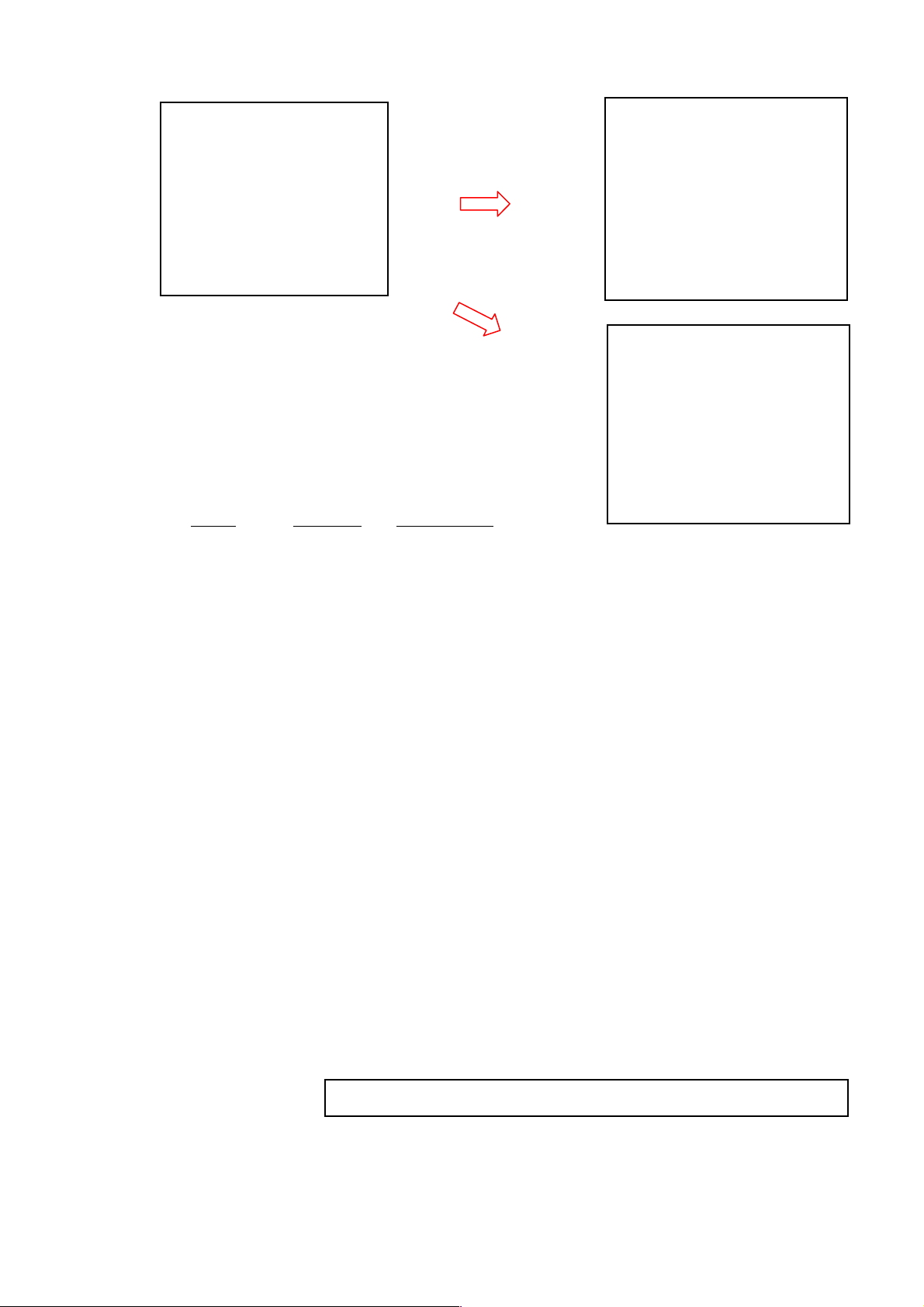
<<<<Memory>>>>(2/3)
<Memory>
<Memory>
<Memory><Memory>
Mode
Mode ::::Normal
ModeMode
Interval
Interval
IntervalInterval
::::Single
2/3
Normal
Normal Normal
Single
SingleSingle
2/3
2/32/3
Select to
Mode:Auto
<Memory>
<Memory><Memory>
Mode
Mode ::::Auto
ModeMode
Interval
Interval ::::Single
IntervalInterval
I/O
I/O ::::OFF
I/O I/O
Level
Level ::::65dB
Level Level
Samp Time
Samp Time ::::Meas Time
Samp Time Samp Time
Sta
Sta::::08/10/10
08/10/10 18:16:00
StaSta
08/10/10 08/10/10
Stp
Stp::::08/10/12 20:16:00
08/10/12 20:16:00
StpStp
08/10/12 20:16:0008/10/12 20:16:00
2/3
Auto
Auto Auto
Single
SingleSingle
OFF
OFFOFF
65dB
65dB65dB
Meas Time
Meas TimeMeas Time
18:16:00
18:16:0018:16:00
2/3
2/32/3
<Memory>
Select to
Mode:Start
<Memory>
<Memory>
<Memory><Memory>
Mode
Mode ::::Start
ModeMode
Interval
Interval ::::Repeat
IntervalInterval
I/O out
I/O out ::::232C
I/O out I/O out
2/3
Start
StartStart
Repeat
RepeatRepeat
232C
232C232C
2/3
2/32/3
Items Default Explanation
● Mode :Normal :Normal:Basic setting
Auto :Automatic measurement, where the following
items are available.
Start :Start of power supply ON automatic measuring
system.
(It records on the memory card simultaneously)
● Interval :Single :Measuring interval setting
Single :The measurement starts with [Start/Stop] key
and is terminated at Meas Time selected .
Repeat :The measurement starts with [Start/Stop] key and
is repeated in every Meas Time selected until
[Start/Stop] key is pressed.
【When Mode:Auto is selected, the following items can be specified】
● I/O :OFF :External output setting
OFF :Default (Data output is disabled).
ON :Outputs data for one second when the data
mory mode is active.
● Level :65dB :65dB :Threshold level is registered (when the level
exceeds it, recording starts), within the range
20-130dB at resolution 1dB
● Samp Time :Meas Time:Meas Time:sampled at interval equal to Meas time.
100ms :sampled at interval 100ms (0.1s).
200ms :sampled at interval 200ms (0.2s).
1s :sampled at interval 1s
** Meas Time is time set with [Meas Time] key (1s~-・・・).
* Select 10s or more in L
Fixed to Mease Time, when when RSR card is installed.
measurement.
Atm5
● Sta : Registers the starting time for recording (YY/MM/DD HH/MM/SS)
(Year/Month/Date, date time/minute/second).
● Stp : Registers the stop time for recording (YY/MM/DD HH/MM/SS)
(Year/Month/Date, date time/minute/second).
Page 27
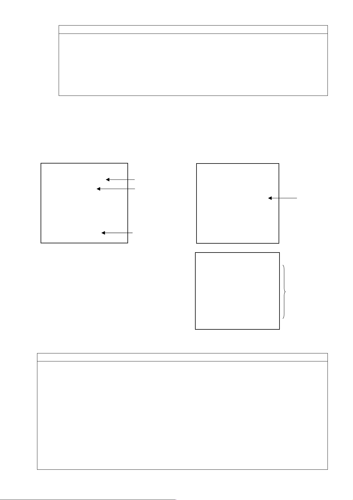
26
NOTE
Measurement starts when the selected level is exceeded after the time specified with
Sta Time, In the following example :
:When the level exceeds 65dB after 18:16 October 10,
Recording starts and the measurement is made once during
the time specified with Meas Time.
Recording is continued, in Interval Repeat mode, until the
level falls or until 20:16 October 12,.
Data is shown according to System Mode.
【When Mode:Start is selected, the following items can be specified】
● I/O :232C :Selection of interface.
232C :RS-232C
USB :USB
※The following items become fixation (It is not possible to change).
<System>
<System>
<System><System>
Mode
Mode ::::Normal
ModeMode
Data delete
Data delete ::::off
Data deleteData delete
LCD cont
LCD cont :*****
LCD contLCD cont
Date
Date y/m/d
y/m/d ::::01/01/01
DateDate
y/m/d y/m/d
Tim
Time h/m/s
e h/m/s ::::00000:00:00
TimTim
e h/m/se h/m/s
Printer
Printer(pc)set
PrinterPrinter
USB out
USB out ::::OFF
USB out USB out
(pc)set::::4800
(pc)set(pc)set
1/3
0:00:00
0:00:000:00:00
1/3
1/31/3
Normal
Normal Normal
off
offoff
:*****
:*****:*****
01/01/01
01/01/0101/01/01
4800
48004800
OFF
OFFOFF
Fixation
Fixation
Fixation
<Memory>
<Memory>
<Memory><Memory>
2/3
2/3
2/32/3
Mode
Mode ::::Start
ModeMode
Interval
Interval ::::Repeat
IntervalInterval
I/O out
I/O out ::::232C
I/O out I/O out
Start
StartStart
Repeat
RepeatRepeat
232C
232C232C
Fixation
●Level Range :20~100dB (Fixation)
<View Mode>
<View Mode><View Mode>
Lp
Lp ::::INST
LpLp
(A)View
(A)View LA05
(A)View(A)View
LAeq
LAeq ::::ON
LAeq LAeq
LAE
LAE ::::OFF
LAE LAE
LAmin
LAmin::::ON
LAminLAmin
LAmax
LAmax::::ON
LAmaxLAmax
3/3
INST
INST INST
LA05 ::::OF
LA05 LA05
ON LA10
LA10 ::::OFF
ONON
LA10 LA10
OFF LA50
LA50 ::::OFF
OFFOFF
LA50 LA50
ON LA90
LA90 ::::OFF
ONON
LA90 LA90
ON LA95
LA95 ::::OFF
ONON
LA95 LA95
3/3
3/33/3
OFFFFF
OFOF
OFF
OFFOFF
OFF
OFFOFF
OFF
OFFOFF
OFF
OFFOFF
Fixation
<View Mode>
●Time weighting :Fast (Fixation)
●Frequency weighting :A (Fixation)
NOTE
・ When Start is selected, it becomes a measurement beginning in[[[[Start/Stop]]]]key input or
power supply ON of this equipment.
・ When Start is selected, the operation result is recorded on the memory card every set time
of "Meas.Time".
・ When Start is selected, cards other than the memory card cannot be used. Please change to
modes other than Start when you use other cards.
When optional card is inserted after this power supply ON of this equipment
:[[[[Card]]]]key invalid operation
At this equipment power supply ON after inserting an optional card
:[[[[Card]]]]key invalid operation or ”Card ERR”is displayed.
・ The RS-232C/USB output is continuously output though the card record stops at that time
when the record of the memory card becomes FULL while measuring it. In this case, please
copy data in the memory card to the personal computer etc. once, and execute the deletion
of the data file of the memory card from this equipment.
Page 28
27
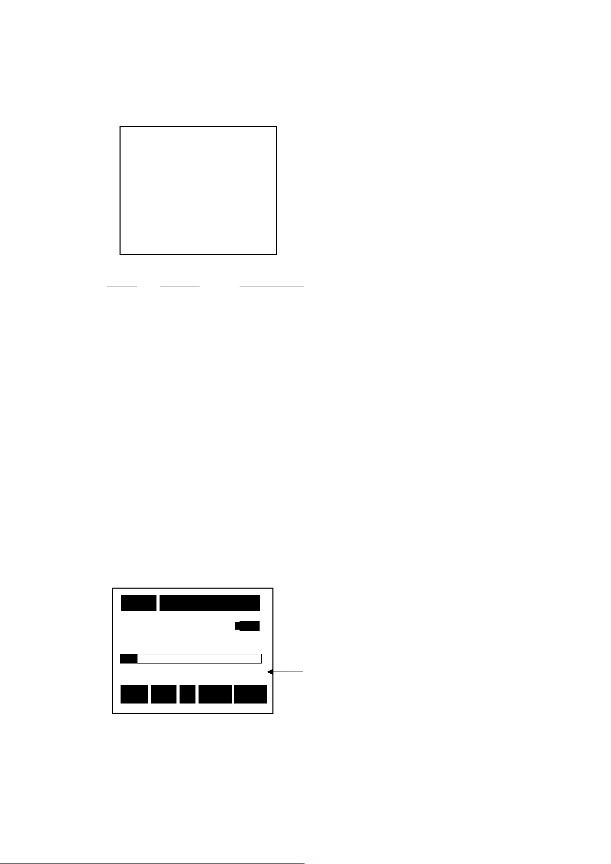
Lp
:I
nstantaneous value
<<<<View Mode>>>> 3/3
63.5 dB
63.5 dB
Select the category of displayed data.
The data registered here is displayed in the standard screen, one by one with [Mode] key pressed
on the main body.
<View Mode>
<View Mode>
・ When TACT is selected for Lp, [LaT] is displayed in display mode.
<Display> When Lp is TACT
<View Mode><View Mode>
Lp
Lp ::::INST
LpLp
(A)View
(A)View LA05
(A)View(A)View
LAeq
LAeq ::::ON
LAeq LAeq
LAE
LAE ::::OFF
LAE LAE
LAmin
LAmin::::ON
LAminLAmin
LAmax
LAmax::::ON
LAmaxLAmax
Items Default Explanation
● L :INST :INST :Data is displayed in each second
TACT :The maximum level is displayed in one second.
In each [Mode] key pushed in the measurement screen, display changes as follows :
・ LA→Leq→LE→Lmin→Lmax→L05→L10→L50→L90→L95
10
10mmmm 000
1010
40
40
130
4040
Stp
Stp
StpStp
Z
3/3
INST
INST INST
LA05 ::::OFF
LA05 LA05
ON LA10
LA10 ::::OFF
ONON
LA10 LA10
OFF LA50
LA50 ::::OFF
OFFOFF
LA50 LA50
ON LA90
LA90 ::::OFF
ONON
LA90 LA90
ON LA95
LA95 ::::OFF
ONON
LA95 LA95
Leq :Equivalent continuous A-weighted sound
LE :Single event sound exposure level
Lmin :Minimum A-weighted sound pressure
Lmax :Maximum A-weighted sound pressure
Lpeak :Peak sound pressure level
000hhhh00
000000
00mmmm00000000ssss
0000
130
130 130
Z Fast L
Fast LA
Z Z
Fast L Fast L
3/3
3/33/3
OFF
OFFOFF
OFF
OFFOFF
OFF
OFFOFF
OFF
OFFOFF
OFF
OFFOFF
(TACT MAX)
pressure level
level
level
AT
T
AA
TT
Display mode
In the case of Lp:TACT
Z:LPT
A:LAT
C:LCT
Page 29
28
63.5 dB
63.5 dB
Measurement Procedure
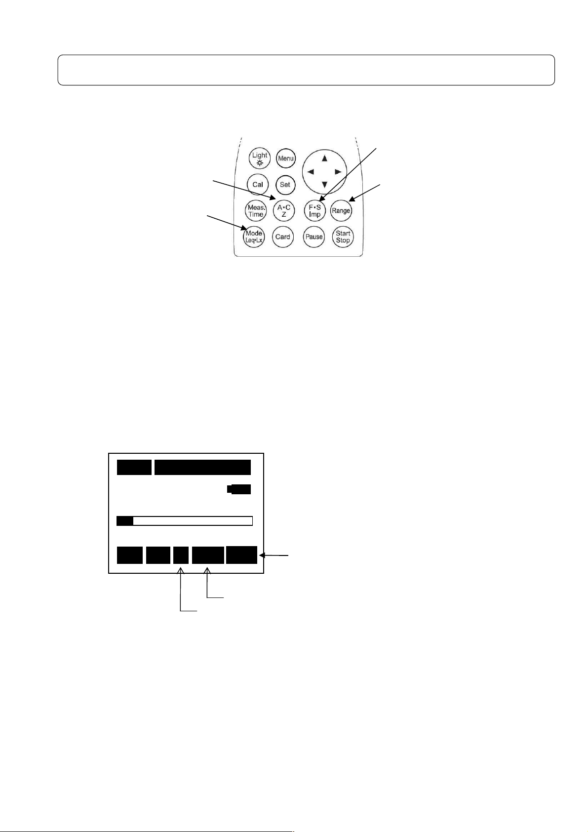
Sound pressure level ((((Lp)))) measurement::::Frequency weighting key Z
①Frequency weighting key
②Display mode key
<<<< Parameter setting >>>>
①Frequency weighting key :Z
③Time weighting key :F, S or Imp
【Method of selecting RangeKey】
Press [Range] key, and choose by cursor keys▲▼, and press [Range] key
again to register.
<<<< Display >>>>
(A・C, Z)
Measure ment is made according to the following procedure.
②Display mode key :Lp
④Range key :Select a range where the bar graph indicates
approximately 2/3 of the full scale.
③Time weighting key
(F:Fast, S:Slow, Imp: Impulse
④[[[[Range] key
1111ssss
000
000hhhh00
000000
00mmmm00000000ssss
0000
40
40
130
4040
130
130 130
Stp
Stp
StpStp
Z
Z Fast Lp
Z Z
Fast Lp
Fast Lp Fast Lp
Time weighting key:Fast, Slow or Imp
Frequency weighting key :Z(Flat)
Display mode
Lp
Page 30
29
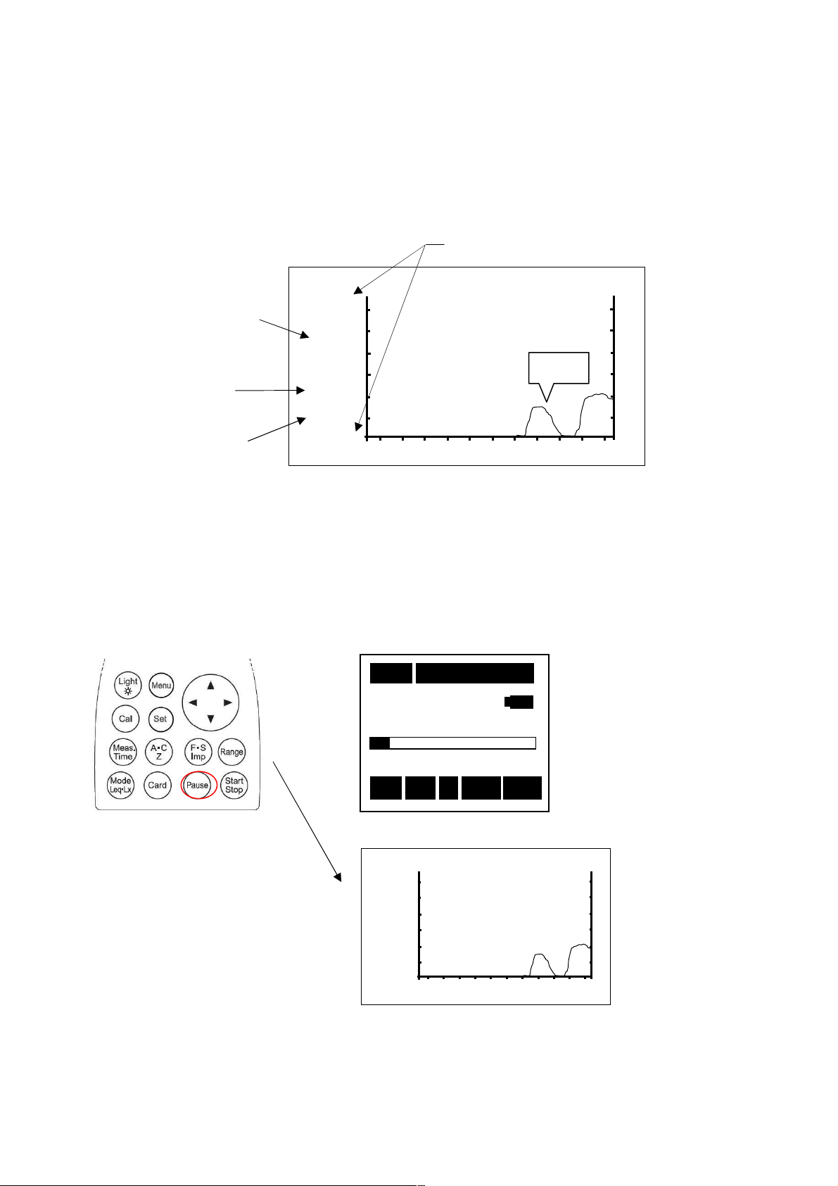
Temporal level display of Sound pressure level (Lp)
Fast
38.6
Fast
63.5
<<<< Parameter setting >:
The temporal level is displayed at each contiguous push (1.5s) of [Mode] key as follows,
returning to the standard display screen when the key is pushed again.
The key operation is similar to the measurement of sound pressure level (Lp).
<<<< Display >>>>
③Instantaneous level:
Per second display
②Frequency
weighting key:
Fast, Slow or Imp
④Display mode key
The instantaneous level is displayed at each about 300ms from right to left.
Data hold
By pushing the [Pause] key, the blinking letter “Pause“ is displayed at the center of the bar
graph, displaying the present instantaneous level. Note that the bar graph itself doesn't pause.
<Standard display>
Pause
→→→
<Temporal level display>
・By pushing the [Pause] key is pushed again, it is released.
>:
>:>:
80dB
dB
Lp
20
①Range
10
10mmmm 000
1010
Stp
Stp
StpStp
130dB
000hhhh00
00mmmm05
000000
0000
63.5 dB
63.5 dB
63.5 dB63.5 dB
Pause
Pause
40
40
4040
PausePause
130
Z
130
130 130
Z Fast
Fast Lp
Z Z
Fast Fast
Pause
dB
Lp
60
05ssss
0505
Lp
Lp Lp
Data
Page 31
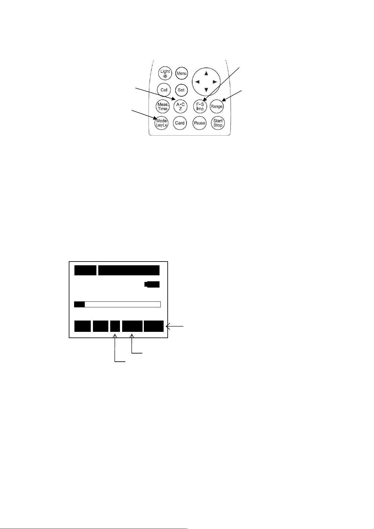
30
A-weighted sound pressure level (LA/LC) measurement:
63.5 dB
63.5 dB
:
::
Frequency weighting key A, C
①Frequency weighting key
②Display mode key
<<<< Parameter setting >>>>
① Frequency weighting key :A or C
③ Time weighting key :F, S or Imp
【Method of selecting [Range] key】
Press [Range] key, and choose by cursor keys▲▼, and press [Range] key
again to register.
<<<< Display >>>>
(A・C, Z)
Measurement is mede according to the following procedure
② Display mode key :L
④ Range key :Select a range where the bar graph indicates
, L
A
C
approximately 2/3 of the full scale.
③Time weighting key
(F:Fast, S:Slow, Imp: Impulse
④[Range] key
1111ssss
000
000hhhh00
000000
00mmmm00
00ssss
0000
0000
40
40
130
4040
130
130 130
Stp
Stp
StpStp
A
A Fast L
A A
Fast LA
Fast L Fast L
A
AA
Time weighting:Fast, Slow or Imp
Frequency weighting:A or C
Display mode
L
or L
A
C
Page 32
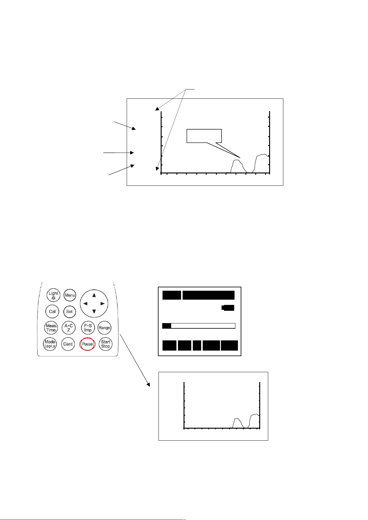
31
Time level display of A-weighted sound pressure level (LA/LC)
Fast
63.5
Fast
63.5
<<<< Parameter setting >>>>
The key operation is similar to the measurement of A-weighted sound pressure level (LA/LC).
<<<< Display >>>>
Instantaneous value:
Per second display
③Time weighting key:
Fast, Slow or Imp
②Display mode key
The instantaneous level is displayed at each about 300ms from right to left.
130dB
dB
LA
40
Data hold
By pushing the [Pause] key, the blinking letter “Pause“ is displayed at the center of the bar
graph, displaying the present instantaneous level. Note that the bar graph itself doesn’t
pause.
<Standard display>
Pause
→→→
<Temporal level display>
・By pushing the [Pause] key again, it is released.
1111ssss
000
63.5 dB
63.5 dB
63.5 dB63.5 dB
40
40
130
4040
Stp
Stp
StpStp
130dB
dB
LA
40
①Range
Data
000hhhh00
000000
Pause
Pause
PausePause
A
A Fast
A A
Pause
00mmmm00
00ssss
0000
0000
130
130 130
Fast L
LA
L L
A
AA
Fast Fast
Page 33
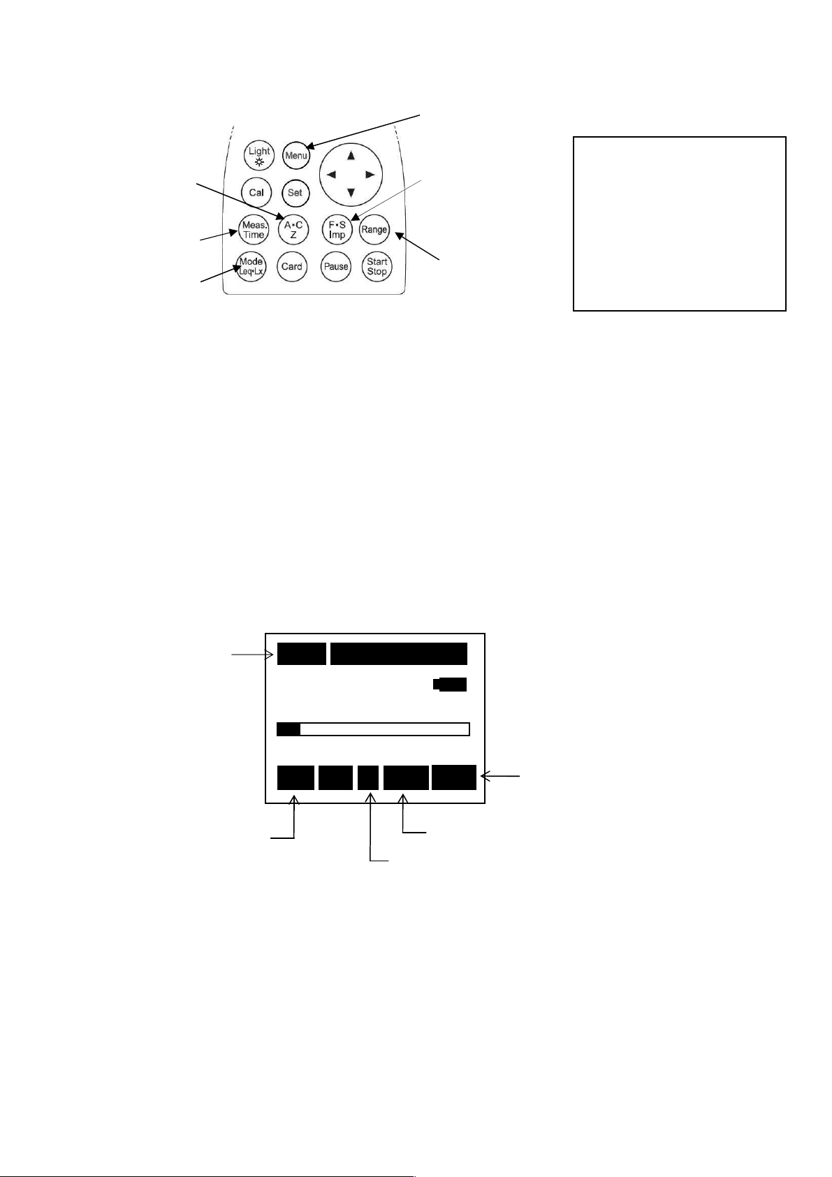
32
Equivalent continuous A-weighted sound pressure level (LAeq)
mode key
63.5 dB
63.5 dB63.5 dB
63.5 dB
measurement
①Frequency
weighting key
(A・C, Z)
⑤Measuring
time key
②Display
<<<< Parameter setting >>>>
1)The key operation is similar to the measurement of A-weighted sound pressure level (LA)
except that it needs [Start/Stop] key input for starting the measurement
(automatic calculation).
2)To display the value Leq, keep the "LAeq” key ON in advance in the <View Mode> 3/3
screen.
① Frequency weighting key :A
② Display mode key :Leq
③ Time weighting key :F or S
④ Range key :Select a range where the bar graph indicates
approximately 2/3 of the full scale.
【Method of selecting [Range] Key】
Press [Range] key, and choose by cursor keys▲▼, and press [Range] key
again to register.
⑤ Measurement time key :1s、3s、5s、10s、1m、5m、10m、15m、30m、1h、8h、24h
and ***(until the [Start/Stop]
<<<< Display >>>>
1s
1s
00
Measurement
1s 1s
000000hhhh00
0000
00mmmm00
0000
2) [Menu] key
③Time weighting
key
(F:Fast, S:Slow)
④[Range] key
00ssss
0000
<<<<Menu>>>>
<View Mode> 3/3
Lp :INST
(A)View LA05 :OFF
LAeq
LAeq ::::ON
LAeq LAeq
LAE :OFF LA50 :OFF
LAmin:OFF LA90 :OFF
LAmax:OFF LA95 :OFF
Stop] key pushed again)
Stop]Stop]
ON LA10 :OFF
ONON
Rec:Blinking during
recording
Stp: Holding state
・ Measurement starts with [Start/Stop] key pushed, and ends up automatically at the
measurement time. Digital display indicates the halfway result at the current point of
time. ( Display “ Rec “ blinks while the measurement.)
・When Interval is set to Repeat in <Memory> 2/3 screen, the measurement is repeated in every
measurement time. (This is used when continuous measurement is needed.)
・By pushing [Start/Stop] key in course of the measurement, calculation is done using the data
so far.
・By pushing [Pause] key in course of the measurement, the calculation can be done without
using the data in the latest 3 or 5 seconds.
・To set this function, see the description of data delete in “Section 4 Menu 2.Menu(1/2) ” .
This function can be set in the Data delete in the <System> 1/3 screen.
・When *** is selected, the final data is calculated and displayed only when [Start/Stop] key is
pushed or 199 hours have gone through.
・All the keys do not respond during the measurement : [Start/Stop], [Mode], [Light]
60
60
130
6060
Stp
Stp
StpStp
130
130 130
A
A Fast Leq
A A
Fast Leq
Fast Leq Fast Leq
Frequency weighting:A
Time weighting:Any of F, S or Imp (doesn't
Display mode
Leq
influence the measurement.)
Page 34
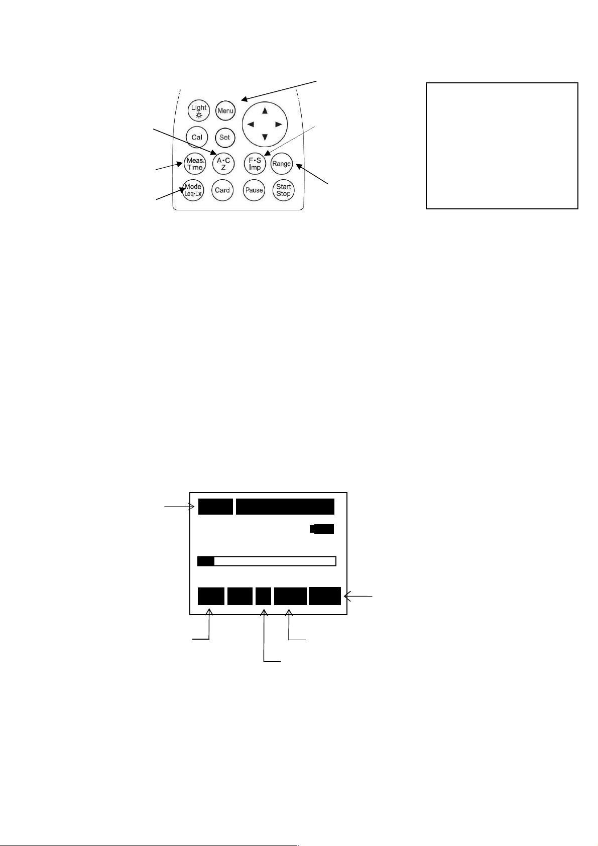
33
Single event sound exposure level((((LAE))))measurement
63.5 dB
63.5 dB
mode key
①Frequency
weighting key
(A・C, Z)
⑤Measuring
time key
①Frequency weighting key :A
【Method of selecting [Range] key】
Press [Range] key, and choose by cursor keys ▲▼, and press [Range] key
again to register.
②Display
<<<< Parameter setting >>>>
1) The key operation is similar to the measurement of A-weighted sound pressure level
(LA) except that it needs [Start/Stop] key input for starting the measurement
(automatic calculation).
2)To display measurements of LE, input ON to "LAE" beforehand by the Menu item.
②Display mode key :LE
③Time weighting key :Any of
④[Range] key :Select a range where the bar graph indicates
approximately 2/3 of the full scale.
⑤Measurement time key :1s、3s、5s、10s、1m、5m、10m、15m、30m、1h、8h、24h
and ***(to the [Start/Stop] key)
<<<< Display >>>>
2) [Menu] key
③Time weighting
key
(F:Fast, S:Slow,
Imp: I mpulse)
④[Range] key
F, S or Imp (doesn't influence the measurement.)
<<<<Menu>>>>
<View Mode> 3/3
Lp :INST
(A)View LA05:OFF
LAeq :OFF LA10:OFF
LLLLAAAAE
E ::::ON
E E
LAmin :OFF LA90:OFF
LAmax :OFF LA95:OFF
ON LA50:OFF
ONON
Measuring time
1s
1s
000
1s 1s
000hhhh00
000000
00mmmm00
0000
00ssss
0000
40
40
130
4040
Stp
Stp
StpStp
130
130 130
A
A Fast L
A A
Fast LE
Fast L Fast L
E
EE
Display mode
LE
Rec:Blinks during
recording
Stp: Holding state
Frequency weighting :A
Time weighting:Any of F, S or Imp (doesn't
influence the measurement.)
・The measurement is similar to the equivalent continuous A-weighted sound pressure level
(L
).
Aeq
Page 35
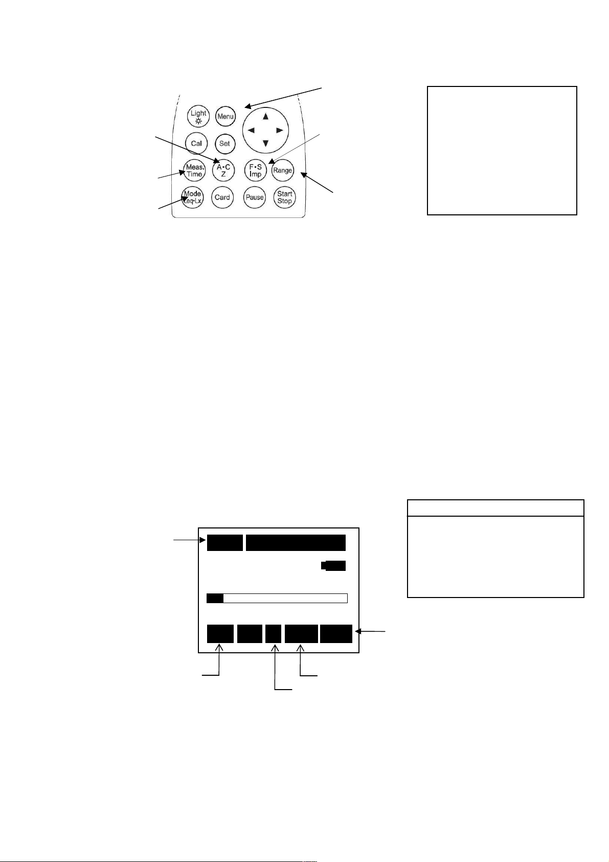
34
Maximum A-weighted Sound pressure Level (L
mode key
63.5 dB
63.5 dB63.5 dB
63.5 dB
time
max/LAmin) Measurement
A
①Frequency
weighting key
(A・C, Z)
⑤Measuring
time key
②Display
2) [Menu] key
③Time weighting
key
(F:Fast, S:Slow,
Imp: I mpulse)
④[Range] key
<<<<Menu>>>>
<View Mode>
<View Mode>
<View Mode><View Mode>
Lp :INST
Lp :INST
Lp :INST Lp :INST
(A)View
(A)View LA05 :OFF
(A)View(A)View
LAeq :OFF LA10 :OFF
LAE :OFF LA50 :OFF
LAmin
LAmin::::ON
LAminLAmin
LAmax
LAmax::::ON
LAmaxLAmax
3/3
ON LA90 :OFF
ONON
ON LA95 :OFF
ONON
<<<< Parameter setting >>>>
1) The key operation is similar to the measurement of A-weighted sound pressure level
(L
)
Aeq
To display measurements of L
the <View Mode> 3/3 screen item.
( similar in L
①Frequency weighting key :A
②Display mode key :L
③Time weighting key :Fast or Slow
④Range key :Select a range where the bar graph indicates
【Method of selecting [Range] key】
Press [Range] key, and choose by cursor keys▲▼, and press [Range] key
again to register.
⑤Measurement time key :1s、3s、5s、10s,1m,5m,10m,15m、30m,1h、8h、24h
<<<< Display >>>>
measurement.)
min
and***(to the [Start/Stop] key)
, input ON to "LAmax" beforehand by
max
or L
max
approximately 2/3 of the full scale.
min
3/3
3/33/3
Measurement
Rec:Blinks during
recording
Stp: Holding state
1s
1s
000
1s 1s
40
40
4040
Stp
Stp
StpStp
000hhhh00
000000
130
A
00mmmm00
0000
130
130 130
A Fast
Fast Lmax
A A
Fast Fast
Frequency weighting :A
00ssss
0000
Display mode
Lmax
LmaxLmax
Time weighting:Fast, Slow
L
or L
max
min
Page 36
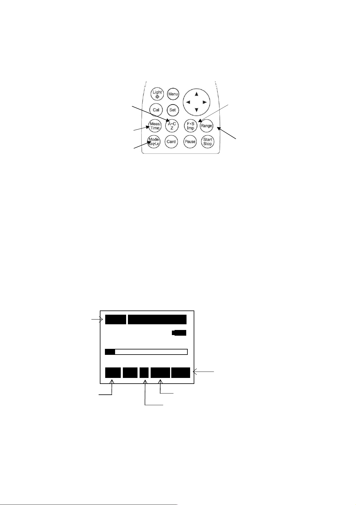
35
Percentile level (LAN) measurement
The L
computation is made
mode key
63.5 dB
63.5 dB63.5 dB
63.5 dB
<<<<Menu>>>>
①Frequency
weighting key
(A・C, Z)
⑤Measuring
time key
①Frequency weighting key :A
③Time weighting key :Fast or Slow
【Method of selecting [Range] Key】
Press [Range] key, and choose by cursor keys▲▼, and press [Range] key
again to register.
⑤Measurement time key :1s、3s、5s、10s,1m,5m,10m,15m、30m,1h、8h、24h
②Display
<<<< Parameter setting >>>>
1)The key operation is similar to the measurement of A-weighted sound pressure level (LAeq)
2)To display the value Lmax, keep the "LA05 ,LA10 ,LA50 ,LA90 ,LA95" key ON in
advance in the <View Mode> 3/3 screen.
②Display mode key :L
④Range key :Select a range where the bar graph indicates
<<<< Display >>>>
Measuring time
Rec:Blinks during
recording
Stp: Halting state
and***(input to the [Start/Stop] key)
10
10mmmm 000
1010
40
40
4040
Stp
Stp
StpStp
000hhhh00
000000
130
A
(To display the Percentile level (L
N
Measurement.)
approximately 2/3 of the full scale.
00mmmm05
0000
130
130 130
A Fast
Fast L05
A A
Fast Fast
2) [Menu] key
<View Mode>
<View Mode>
<View Mode><View Mode>
Lp :INST
Lp :INST
Lp :INST Lp :INST
③Time weighting
key
(F:Fast, S:Slow,
Imp: I mpulse)
④[Range] key
05ssss
0505
Display mode
L05
L05L05
Time weighting:Fast, Slow
Frequency weighting :A
L05 ,L10 ,L50 ,L90 ,L95
(A)View
(A)View
(A)View (A)View
LAeq :OFF LA10
LAE :OFF LA50
LAmin:OFF LA90
LAmax:OFF LA95
at sampling rate 100msec,
which tends to influence the
acculacy in the condition of
measureing time less than
10sec.
LA05
)
N
NOTE
N
3/3
3/3
3/33/3
ON
ONON
ON
ONON
ON
ONON
ON
ONON
ON
ONON
LA05 ::::ON
LA05 LA05
LA10 ::::ON
LA10 LA10
LA50 ::::ON
LA50 LA50
LA90 ::::ON
LA90 LA90
LA95 ::::ON
LA95 LA95
Page 37
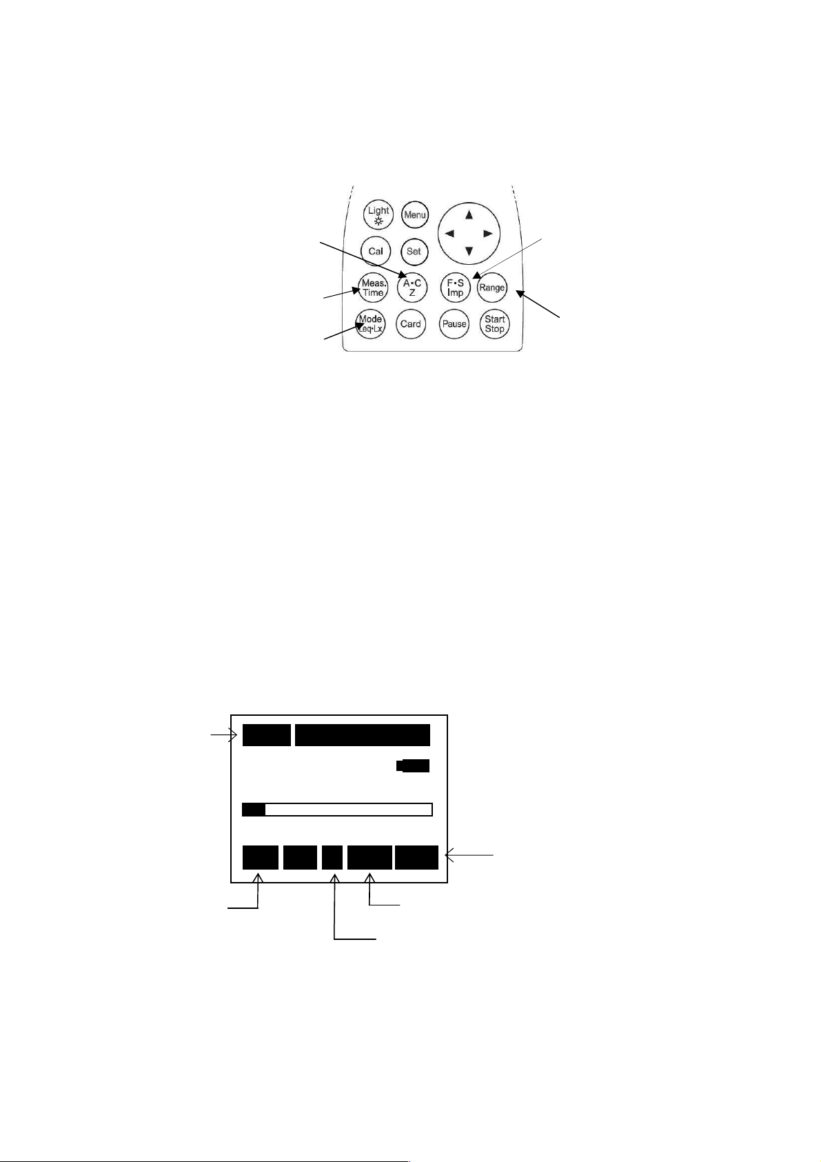
36
Peak sound pressure level (L
63.5 dB
63.5 dB63.5 dB
63.5 dB
mode ke
y
The peak sound pressure level is peak sound pressure level of the sound wave before
smoothed with the time weighting characteristics.
L
is peak sound level for Z characteristics.
peak
<<<< Parameter setting >>>>
Measurement is mede according to the following procedure
① Frequency weighting key :Z
② Display mode key :Peak
③ Time weighting key :F, S or Imp
④ Range key :Select a range where the bar graph indicates
【Method of selecting [Range] key】
Press [Range] key, and choose by cursor keys▲▼, and press [Range] key
again to register.
⑤ Measurement time key :1s、3s、5s、10s,1m,5m,10m,15m、30m,1h、8h、24 h
⑥ and***(input to the [Start/Stop] key)
<<<< Display >>>>
Measuring time
Rec:Blinks during
recording
Stp: Holding state
①Frequency
weighting key
(A・C, Z)
⑤Measuring
time key
②Display
10
10mmmm 000
1010
40
40
130
4040
Stp
Stp
StpStp
000hhhh00
000000
Z
Z Fast Peak
Z Z
) measurment
peak
approximately 2/3 of the full scale.
00mmmm05
05ssss
0000
0505
130
130 130
Fast Peak
Fast PeakFast Peak
Frequency weighting :Z
③Time weighting
key
(F:Fast, S:Slow,
Imp: I mpulse)
④[Range] key
Time weighting:Fast, Slow, Imp
Display mode
Peak
Page 38
37
C-weighted peak sound pressure level (L
63.5 dB
63.5 dB63.5 dB
63.5 dB
(do
esn't influence the measurement.
)
mode key
The peak sound level is peak sound pressure level before smoothed with the time weighting
characteristics.
Lcpeak is wavy peak level of C characteristic.
<<<< Parameter setting >>>>
【Method of selecting [Range] key】
Press [Range] key, and choose by cursor keys▲▼, and press [Range] key
again to register.
Measuring time
Rec:Blinks during
recording
Stp: Holding state
① Frequency weighting
key (A・C, Z)
⑤Measuring
time key
②Display
Measurement is mede according to the following procedure
① Frequency weighting key :C
② Display mode key :Fixed to Peak
③ Time weighting key :Any of
(doesn't influence the measurement.)
④ Range key :Select a range where the bar graph indicates
approximately 2/3 of the full scale.
⑤ Measurement time key :1s、3s、5s、10s,1m,5m,10m,15m、30m,1h、8h、24h
and***(input to the [Start/Stop] key)
The measurement starts with [Start/Stop] key.
<<<< Display >>>>
10
10mmmm 000
1010
40
40
4040
Stp
Stp
StpStp
・ Measurement starts with [Start/Stop] key pushed, and ends up automatically at the
measurement time. Digital display indicates the halfway result at the current point of time.
( Display “ Rec “ blinks while the measurement.)
・By pushing [Start/Stop] key in course of the measurement, calculation is done using the data
so far.
・When *** is selected, the final data is calculated and displayed only when [Start/Stop] is
pushed or 199 hours have gone through.
000hhhh00
000000
130
C
00mmmm05
05ssss
0000
0505
130
130 130
C Fas
Fast Peak
C C
t Peak
FasFas
t Peakt Peak
Frequency weighting :C
Time weighting:Any of F, S or Imp
) measurement
Cpeak
F, S or Imp
Display mode
Peak
③Time weighting
key
(F:Fast, S:Slow,
Imp: I mpulse)
④[Range] key
Page 39
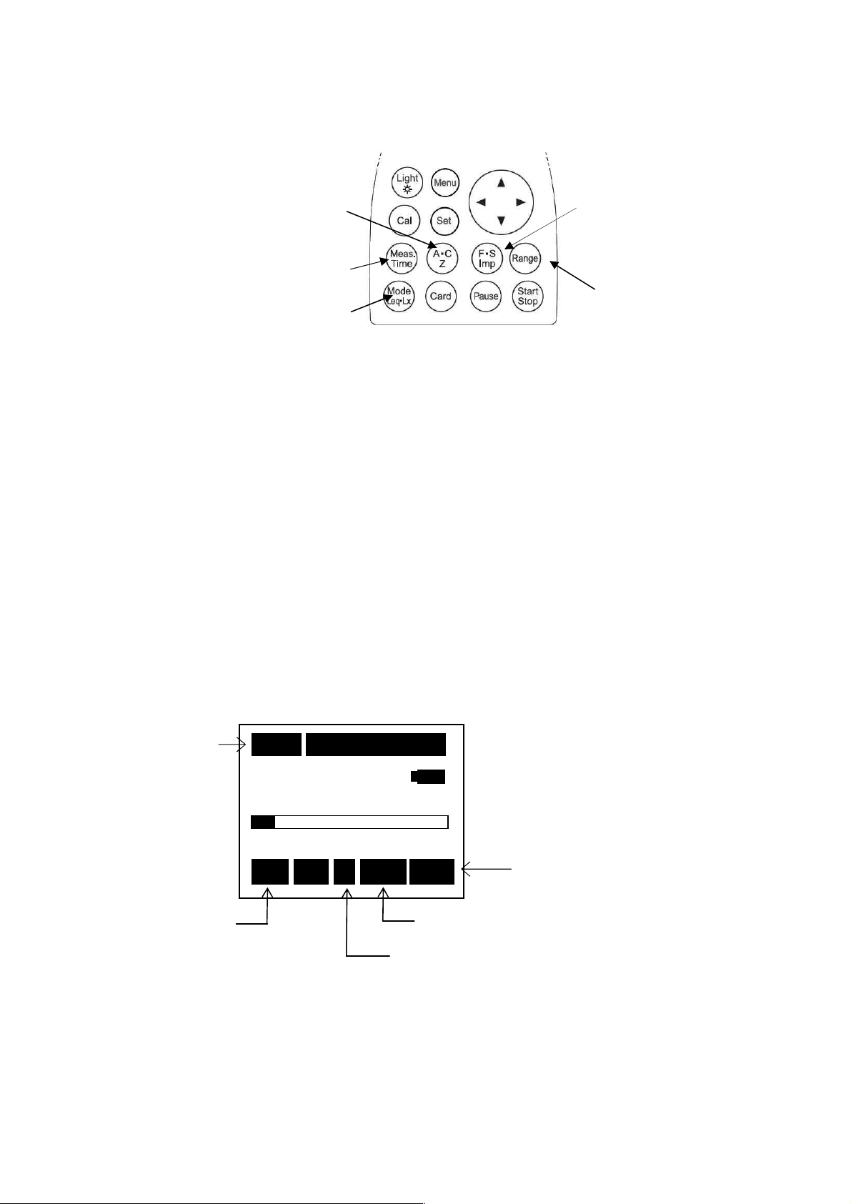
38
C-weighted equivalent continuous sound pressure level (L
63.5 dB
63.5 dB
Lceq is C-weighted equivalent continuous sound pressure level.
<<<< Parameter setting >>>>
【Method of selecting [Range] key】
Press [Range] key, and choose by cursor keys▲▼, and press [Range] key
again to register.
<<<< Display >>>>
Measuring time
Rec:Blinks during
recording
Stp: Holding state
①Frequency weighting
key (A・C, Z)
⑤Measuring time key
②Display mode key
Measurement is mede according to the following procedure
① Frequency weighting key :C
② Display mode key :Leq
③ Time weighting key :F or S
④ Range key :Select a range where the bar graph indicates
approximately 2/3 of the full scale.
⑤ Measurement time key :1s、3s、5s、10s,1m,5m,10m,15m、30m,1h、8h、24h
and***(input to the [Start/Stop] key)
The measurement starts with [Start/Stop] key.
10
10mmmm 000
1010
40
40
4040
Stp
Stp
StpStp
000hhhh00
000000
130
C
00mmmm05
05ssss
0000
0505
130
130 130
C Fast
Fast
C C
Fast Fast
Frequency weighting :C
Leq
Leq
LeqLeq
Time weighting: F or S
Display mode
Leq
③Time weighting
key
(F:Fast, S:Slow,
Imp: I mpulse)
④[Range] key
) measurement
Ceq
Page 40
39
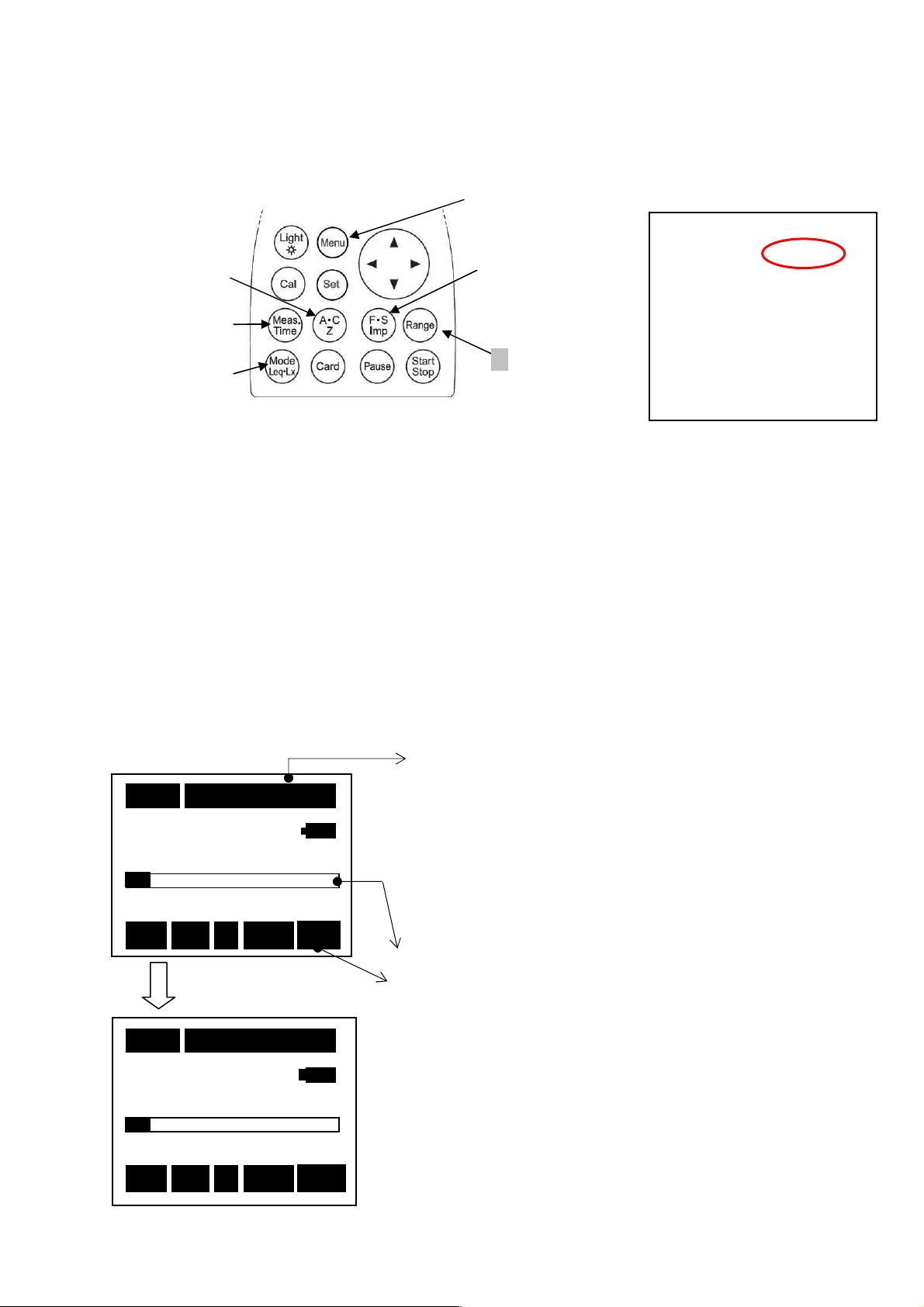
Power average value of the maximum sound pressure level in a given
M
easurement time 10s (second)
display
63
6363
63
....
5555
dB
dBdB
dB
interval (L
Power average value of the maximum sound pressure level in a given interval (L
average of the maximum value of A-weighted sound pressure level in successive 5-sec intervals.
It can be measured only when A characteristics is selected in the standard screen.
①Frequency
Weighting
④Measurement
【Method of selecting[Range] key】
Press [Range] key, and choose by cursor keys▲▼, and press [Range]] key
again to register.
key
②Display
<<<< Parameter setting >>>>
<<<< Display >>>>
key
mode
Mode: Normal in < System>1/3 screen is changed to Mode:L
Menu screen. The screen for power average of the maximum value appears when the
Measurement is mede according to the following procedure
① Frequency weighting key :A
② Display mode key :LA or tm5
③ Time weighting key :F or S
④ Range key :Select a range where the bar graph indicates
⑤ Measurement time key :1s, 3s, 5s, 10s, 1m, 5m, 10m, 15m, 30m, 1h, 8h, 24h
The measurement starts with [Start] key.
) measurement
Atm5
1) [Menu] key
③Time weighting key
(F:Fast,
S:Slow,
Imp: I mpulse)
④[Range] key
change is fixed and resisted with [Set] key.
approximately 2/3 of the full scale.
and***(input to the [Start/Stop] key)
) is power
Atm5
<<<<Menu>>>>
<System>
<System>
<System><System>
Mode
Mode ::::LAtm5
ModeMode
Data delet
Data delet ::::off
Data deletData delet
LCD cont
LCD cont :***
LCD contLCD cont
Date
Date y/m/d
y/m/d ::::01/01/01
DateDate
y/m/d y/m/d
TTTTime h/m/s
ime h/m/s ::::00:00:00
ime h/m/sime h/m/s
Printer(pc)set
Printer(pc)set ::::9600
Printer(pc)set Printer(pc)set
USB out
USB out ::::OFF
USB out USB out
with the ▲▼key in
Atm5
1/3
LAtm5
LAtm5LAtm5
off
offoff
:***
:***:***
01/01/01
01/01/0101/01/01
00:00:00
00:00:0000:00:00
9600
96009600
OFF
OFFOFF
1/3
1/31/3
1111
10
10mmmm
000
000hhhh00
00mmmm00
1010
000000
0000
00ssss
0000
--.-
--.-
Bar: Displays the current instantaneous level.
LA or tm5
Press[[[[Start/Stop Set]]]]key
--.---.-
40
40
4040
Stp
Stp
A
Stp Stp
10
10mmmm
000
1010
000hhhh00
000000
40
40
4040
Rec
Rec
A
RecRec
↑
.
The Rec blinks with [Start/Stop] key input
dB
dB
dBdB
130
A Fast
A A
130
130
130 130
Fast
FastFast
00mmmm00
0000
130
130 130
A Fast
Fast
A A
FastFast
L
LA
LL
00ssss
0000
L
A
AA
LA
A
LL
AA
00h00m00s
00h00m01s
00h00m02s
・
00h00m09s ← End in ten seconds
00h00m00s ← The following measurement
*When <Memory>2/3 screen Intr:Single is measured, it
becomes Repeat continuous work as the measurement
time display.
← Count-up timer for the measurement
← Starts with display ――. ― when the measurement
mode is tm5 .
Measurement value is displayed every five second.
← The bar displays the instantaneous level in every
0.1 second.
← L
Current level is displayed with LA selected value.
and tm5 can be changed.
A
Page 41
40
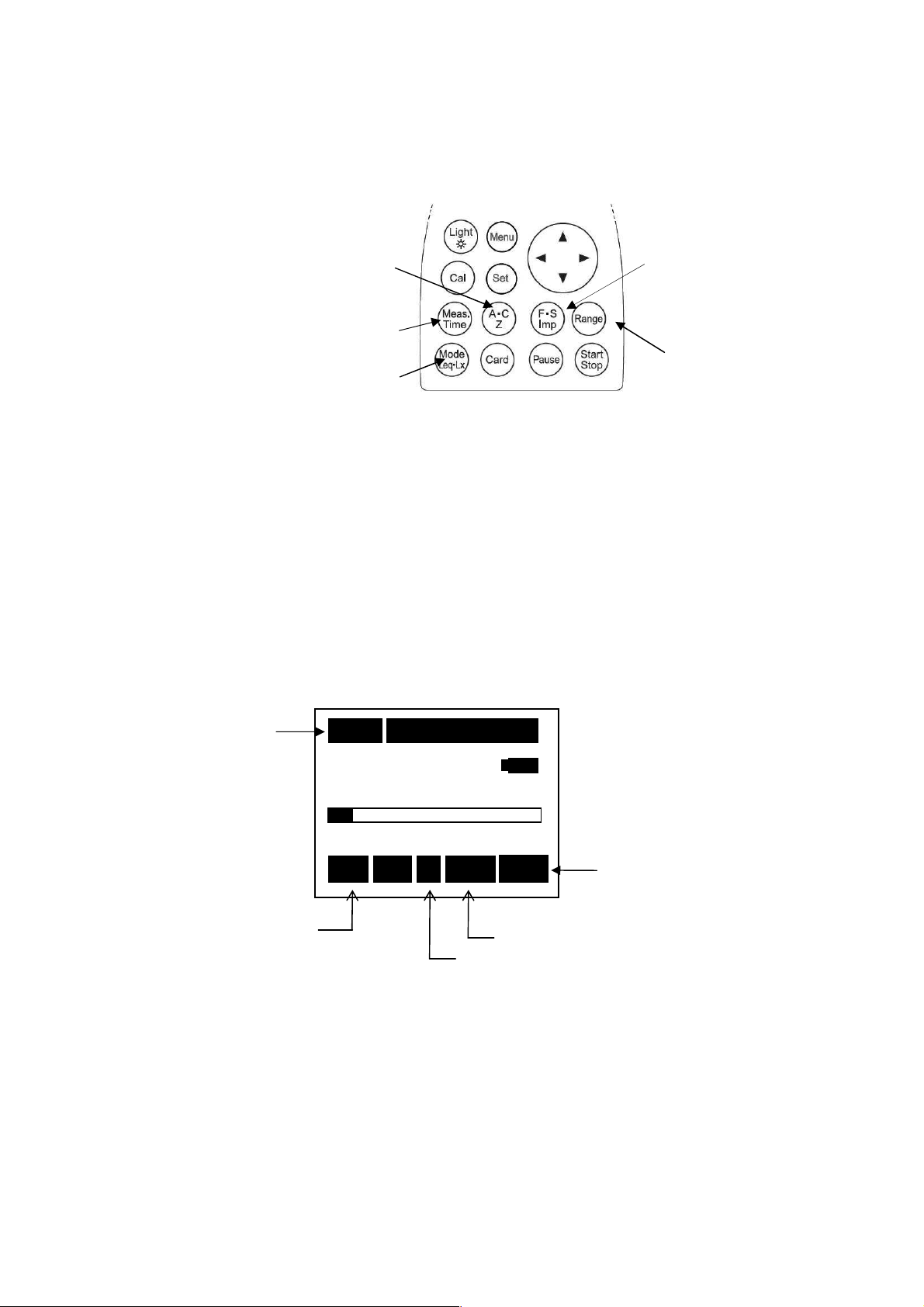
Impulse sound pressure level(LAI) measurement
63.5 d
63.5 d63.5 d
63.5 d
BBBB
Impulse sound pressure level (LAI) is A-weighted sound pressure level with time weighting
characteristics, ‘Impulse’.
It can be used only when A characteristics is selected in the default screen.
<<<< Parameter setting >>>>
【Method of selecting [Range] key】
Press [Range] key, and choose by cursor keys▲▼, and press [Range] key
again to register.
<<<< Display>>>>
Measuring time
① Frequency weighting
key (A・C, Z)
⑤Measuring time key
②Display mode key
Measurement is mede according to the following procedure
① Frequency weighting key :A
② Display mode key :L
③ Time weighting key :Imp
④ Range key :Select a range where the bar graph indicates
10
Rec:Blinks during
recording
Stp: Holding state
10mmmm 000
1010
40
40
4040
Stp
Stp
StpStp
000hhhh00
000000
130
A
A Imp L
A A
A
approximately 2/3 of the full scale.
00mmmm05
05ssss
0000
130
130 130
Imp LA
Imp LImp L
Frequency weighting :A
0505
A
AA
Time weighting: Imp
③Time weighting
key
(F:Fast, S:Slow,
Imp: I mpulse)
④[Range] key
Display mode
LA
Page 42
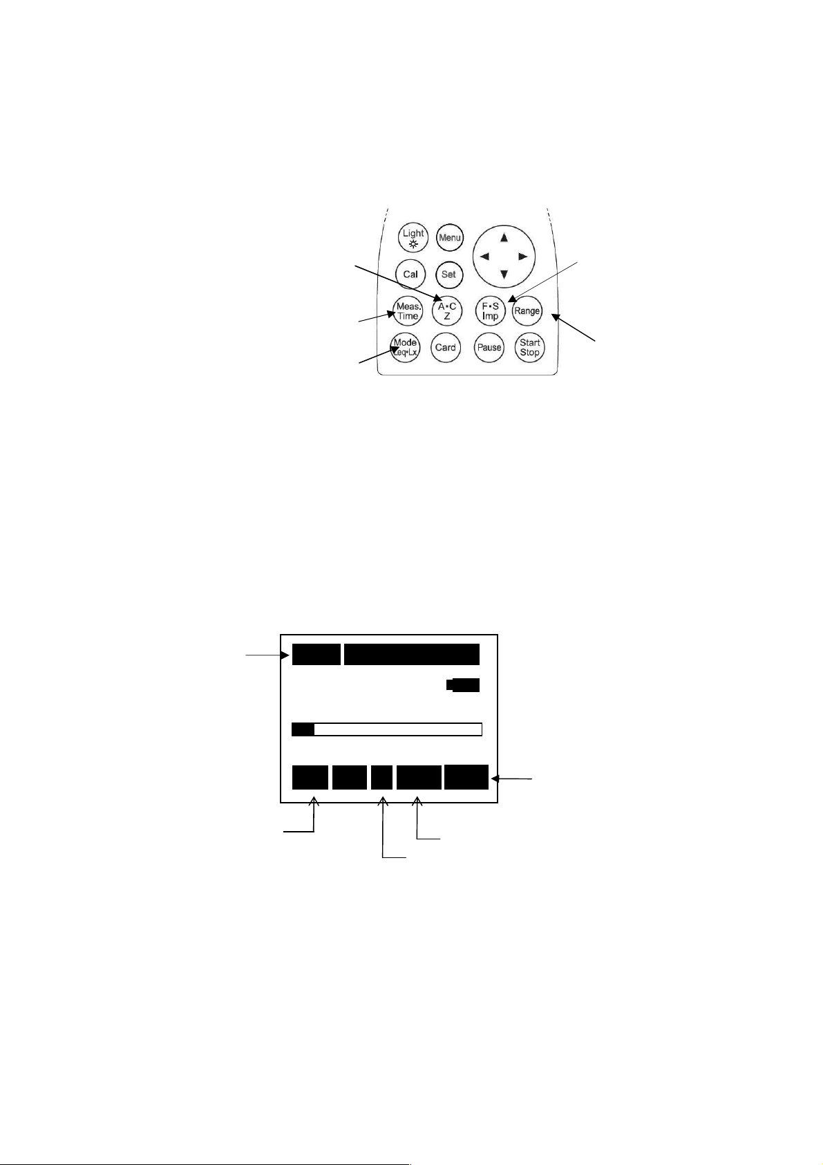
41
63.5 dB
63.5 dB
Impulse equivalent continuous A-weighted sound pressure level (L
AIeq
)
measurement
Impulse equivalent continuous A-weighted sound pressure level (L
continuous sound pressure level with time weighting characteristics, ‘Impulse’.
It can be used only when A characteristics is selected in the default screen.
<<<< Parameter setting >>>>
【Method of selecting [Range] key】
Press [Range] key, and choose by cursor keys▲▼, and press [Range] key
again to register.
<<<< Display>>>>
Measuring time
Rec:Blinks during
recording
Stp: Holding state
① Frequency weighting
key (A・C, Z)
④Measuring time key
⑤Display mode key
Measurement is mede according to the following procedure
① Frequency weighting key :A
② Display mode key :Leq
③ Time weighting key :Imp
④ Range key :Select a range where the bar graph indicates
approximately 2/3 of the full scale.
10
10mmmm 000
1010
40
40
4040
Stp
Stp
StpStp
000hhhh00
000000
130
A
A Imp Leq
A A
00mmmm05
05ssss
0000
130
130 130
Imp Leq
Imp LeqImp Leq
Frequency weighting :A
0505
Display mode
Leq
Time weighting: Imp
) is equivalent
AIeq
③Time weighting
key
(F:Fast, S:Slow,
Imp: I mpulse)
④[Range] key
Page 43
42
Record of memory
【【【【Nomal】】】】 mode
<Memory>
<Memory>
<Memory><Memory>
Mode
Mode ::::Normal
ModeMode
Interval
Interval ::::Single
IntervalInterval
Mode :Normal :Normal :Normal measurement
● Interval :Single :Measuring interval setting
2/3
2/3
2/32/3
Normal
Normal Normal
Single
SingleSingle
Memory function
Single :The measurement starts with[Start/Stop] key and
is terminated at Meas Time selected .
Repeat :The measurement starts with [Start/Stop] key and
is repeated in every Meas Time selected until
[Start/Stop] key is pressed.
Page 44
43
【【【【Auto】】】】 mode
Fixed to Mease Time, when when RSR card is installed,
<<<< Operation >>>>
By changing Mode: Normal in < Memory>2/3 of [Menu] screen to Mode: Auto with the
▲▼key , and fixing it with [Set] key, the following screen appears:
<Memory>
<Memory>
Select to
Mode:Auto
<Memory><Memory>
Mode
Mode ::::Normal
ModeMode
Interval
Interval ::::Single
IntervalInterval
2/3
Normal
Normal Normal
Single
SingleSingle
2/3
2/32/3
<Memory>
<Memory>
<Memory><Memory>
Mode
Mode ::::Auto
ModeMode
Interval
Interval ::::Single
IntervalInterval
I/O
I/O ::::OFF
I/O I/O
Level
Level ::::65dB
Level Level
Samp Time
Samp Time :Meas Time
Samp Time Samp Time
Sta : 08/10/10
Sta : 08/10/10 18:16:00
Sta : 08/10/10 Sta : 08/10/10
Stp : 08/10/12 20:16:00
Stp : 08/10/12 20:16:00
Stp : 08/10/12 20:16:00Stp : 08/10/12 20:16:00
2/3
Auto
AutoAuto
Single
SingleSingle
OFF
OFFOFF
65dB
65dB65dB
Meas Time
Meas TimeMeas Time
18:16:00
18:16:0018:16:00
2/3
2/32/3
Mode :Auto :Automatic measurement, where the following items
are available.
Interval :Single :Measuring interval setting
Single :The measurement starts with [Start/Stop] key and
is terminated at Meas Time selected .
Repeat :The measurement starts with [Start/Stop] key and
is repeated in every Meas Time selected until
[Start/Stop] key is pressed.
I/O :OFF :External output setting
OFF :Default (Data output is disabled).
ON :Outputs data for one second when the data
mory mode is active.
Level :Threshold level is registered (when the levelexceeds it, recording starts)
Samp Time :Meas Time:Meas Time:sampled at interval equal to Meas time.
100ms :sampled at interval 100ms (0.1s).
200ms :sampled at interval 200ms (0.2s).
1s :sampled at interval 1s
** Meas Time is time set with [Meas Time] key (1s~-・・・).
* Select 10s or more in L
measurement.
Atm5
Sta : Registers the starting time for recording (YY/MM/DD HH/MM/SS)
(Year/Month/Date, date time/minute/second).
Stp : Registers the stop time for recording (YY/MM/DD HH/MM/SS)
(Year/Month/Date, date time/minute/second)
<The internal SRAM and Memory Card(SD Card) The contents of the record>
Set value of
Samp Time
100ms
200ms
1s
Meas Time
Sound pressure level LA LC Lp
Equivalent continuous sound pressure level
Sound exposure level
Maximum sound pressure level
Minimum sound pressure level
Percentile (5%) sound pressure level
Percentile sound
pressure level
(LAN)
Percentile (10%) sound pressure level
Percentile (50%) sound pressure level
Percentile (90%) sound pressure level
Percentile (95%) sound pressure level
Peak sound pressure level
Style A C Z
L
LAE
L
Amax
L
Amin
L
L
L
L
L
―
Aeq
A05
A10
A50
A90
A95
L
L
Ceq
― ―
― ―
― ―
― ―
― ―
― ―
― ―
― ―
Cpeak
―
L
peak
Page 45
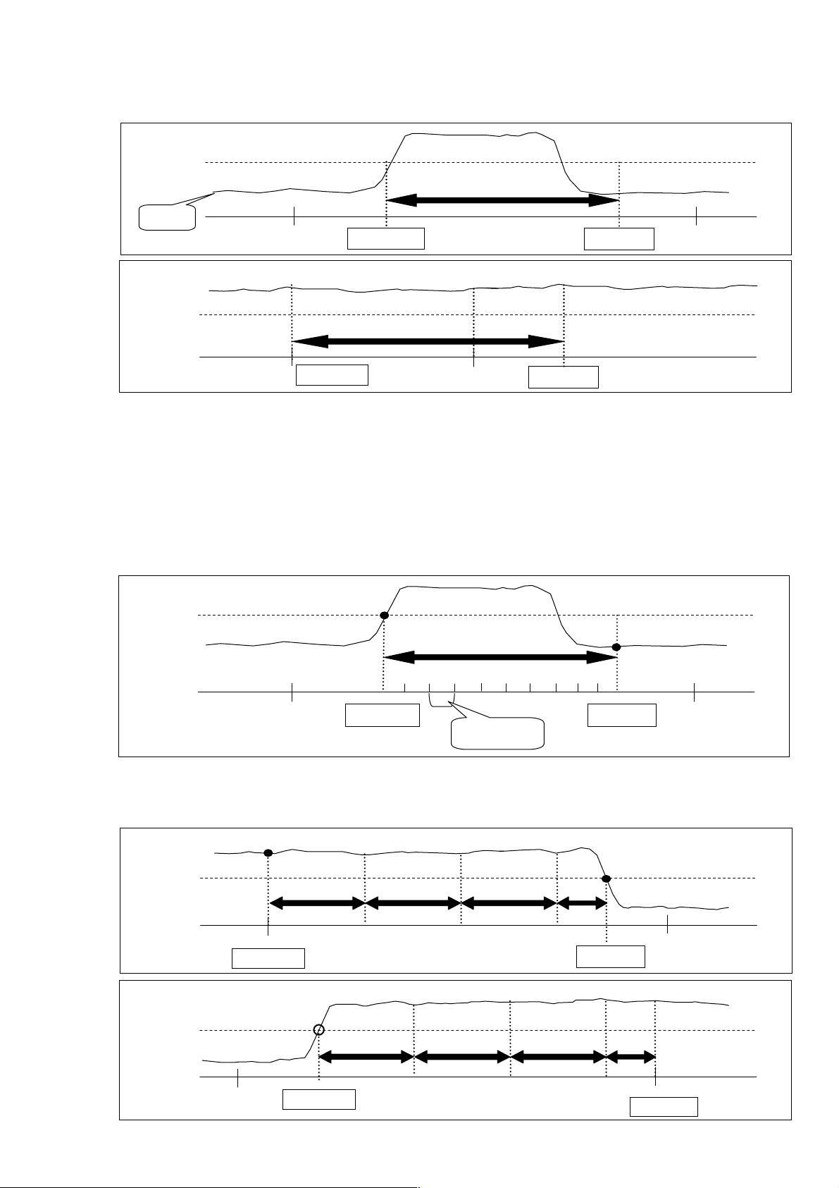
44
≪≪≪≪Interval :::: Single At time of setting≫≫≫≫
Level
3
●Samp Time : Meas.Time at time of setting
If instantaneous value is beyond a set point, I record for once of “Meas.Time”.
instantaneous
value
setting
Meas.Time
Sta
Record start
Record end
Stp
Time
Instantaneous
value
setting
Meas.Time
Sta
Record start
Stop
Record end
Time
●Samp Time :( 100ms / 200ms / 1s ) at time of setting
If instantaneous value is beyond a setting level, record it during one second by setting time of
Samp Time ( 100ms / 200ms / 1s ).
When there is no memory card (SD card): 1S and the record are one data at the measurement
time for the sampling duration of the setting.
When there is a memory card (SD card): 1S and the record are the numbers at the
measurement
time for a set sampling duration of one second.
Instantaneous
value
setting
1s
Sta
Record start
Samp Time
Record end
Stp
Time
≪≪≪≪Interval :::: Repeat At time of setting≫≫≫≫
Level of instantaneous value is less than a setting level or records it until record stop time.
Instantaneous
value
setting
Meas.Time or Samp Time
Start
Record start
1
2
3
4
Stop
Record end
Instantaneous
value
setting
Start
Meas.Time or Samp Time
Record start
1
2
4
Stop
Record end
Page 46
45
63
6363
63
....
5555
dB
dBdB
dB
63
6363
63
....
5555
dB
dBdB
dB
< Standby screen > < During a measurement >
↑
10
10mmmm 000
1010
40
40 AUTO 130
4040
Stp
Stp
StpStp
The Stp blinks when [Start Stop] Key is pressed to confirm the stand-by state.
000hhhh00
000000
AUTO 130
AUTO 130 AUTO 130
AAAA Fast
00mmmm00000000ssss
0000
Fast Lp
Fast Fast
Default screen
Lp
LpLp
10
10mmmm 000
1010
40
40
4040
Rec
Rec
RecRec
000hhhh00
000000
AUTO
AAAA Fast
00mmmm00000000ssss
0000
AUTO 130
130
AUTOAUTO
130 130
Fast Lp
Fast Fast
Lp
LpLp
Page 47
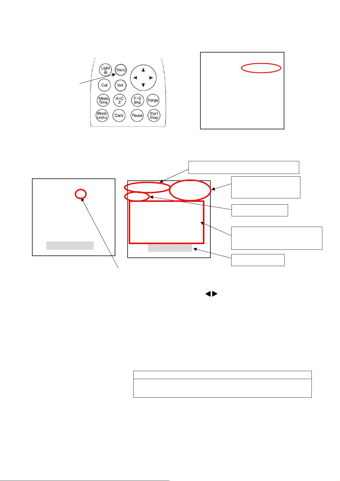
46
12:18:20
12:18:20 12:18:20
12:18:20
Data recall from the memory
Time constant
D
isplay blinks
<<<<Operation>>>>
Menu key
The Mode: Normal in <System>1/3 screen is changed to Mode: Mem call with ▲▼key,
which then leads to the memory display screen by pressing [Set] key. .
【external Memory Card (SD card)】
【internal SRAM】
Memory number, Sampling time
001/014
001/014 10
001/014001/014
FAST
FAST
FASTFAST
LLLLAeq
Aeq
AeqAeq
LAE
LAE ::::48.6
LAELAE
Lmin
Lmin ::::42.2
LminLmin
Lmax
Lmax::::77.5
LmaxLmax
10mmmm 08/10/10
1010
****11112:18:20
:
:45.3 LA05
45.3 LA05::::66.2
::
45.3 LA0545.3 LA05
48.6
48.6 48.6
42.2 LA90
42.242.2
77.5 LA95
77.5 77.5
Memor
Memory Call Ex
y Call Ex
MemorMemor
y Call Ex y Call Ex
08/10/10
08/10/1008/10/10
2:18:20
2:18:202:18:20
66.2
66.266.2
LA10
LA10::::66.2
LA10LA10
LA50
LA50::::66.2
LA50LA50
LA90::::66.2
LA90 LA90
LA95::::66.2
LA95LA95
66.2
66.266.2
66.2
66.266.2
66.2
66.266.2
66.2
66.266.2
001/014
001/014 10
001/014001/014
FAST
FAST
FAST FAST
LAeq
LAeq
LAeqLAeq
LAE
LAE ::::48.6
LAELAE
Lmin
Lmin ::::42.2
LminLmin
Lmax
Lmax::::77.5
LmaxLmax
10mmmm 08/10/10
1010
:
45.3
5.3 LA05
:::444
5.3 5.3
48.6 LA10
48.6 48.6
42.2 LA90
42.2 42.2
77.5 LA95
77.5 77.5
Memory Call IN
Memory Call IN
Memory Call INMemory Call IN
08/10/10
08/10/1008/10/10
LA05::::66.2
LA05LA05
LA10::::66.2
LA10LA10
LA50
LA50::::66.2
LA50LA50
LA90::::66.2
LA90LA90
LA95::::66.2
LA95LA95
66.2
66.266.2
66.2
66.266.2
66.2
66.266.2
66.2
66.266.2
66.2
66.266.2
"*" is displayed in Repeat of the external Memory Card (SD Card)
The first data of Repeat data are displayed.
Each data is displayed with key at Repeat.
Select the data with ▲▼ key, accelerating by keeping on pushing the cursor
On pressing Card key in the state of Memory Call, it changes to Memory Call Ex and the
data in the Card is displayed
Memory Call IN:Data stored in the internal SRAM.
Memory Call Ex:Date stored in the external Memory Card (SD Card)
[Start/Stop] key pressed starts data communication displayed data.
※※※※To return to the default screen, change Mode: Memory call in < System>1/3 screen
to Mode :Normal with ▲▼ key.
Whenever measuring it, the measurement data preserved
in an internal memory is overwrited.
<System>
<System>
<System><System>
Mode
Mode ::::Mem call
ModeMode
Data delet
Data delet ::::off
Data deletData delet
LCD cont
LCD cont :***
LCD contLCD cont
Date
Date y/m/d
y/m/d ::::01/01/01
DateDate
y/m/d y/m/d
Time
Time ::::00:00:00
TimeTime
Printer(pc)set
Printer(pc)set ::::9600
Printer(pc)set Printer(pc)set
USB out
USB out ::::OFF
USB out USB out
1/3
9600
96009600
1/3
1/31/3
Mem call
Mem callMem call
off
offoff
:***
:***:***
01/01/01
01/01/0101/01/01
00:00:00
00:00:0000:00:00
OFF
OFFOFF
Date/time of the
Measurement
Symbol *** refers to the item
which is set OFF in Menu screen.
NOTE
Page 48
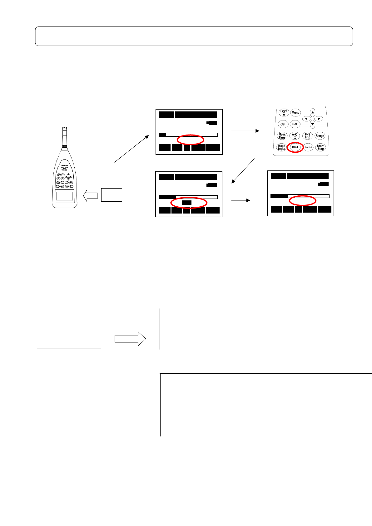
47
How to use the Memory Card ( SD Card ----Standard---- )
4400
1
1
3300
4400
1
1
3300
4400
STD
STD
13
13
00
The measured data can be stored on the memory card (SD card) to be processed by personal
computer. When the memory card (SD card) is inserted after the POWER of this equipment
supply is turned on, display【STD】blinks. The memory card (SD card) is recognized automatically,
blinks STD is a standby display on starting the measurement if the power switch is turned on with
the memory card (SD card) inserted.
Card Installation
00003s
3s 000
000hhhh00
000000
00mmmm00
0000
STD
STD
STDSTD
Fast La
Fast LaFast La
3s3s
63.5 dB
63.5 dB
63.5 dB63.5 dB
Stp
Stp A
A Fast La
StpStp
A A
00ssss
0000
① Insert the a card.
Card
After 3s
②STD lighted.
00003s
3s 000
000hhhh00
3s 3s
63.5 dB
63.5 dB
63.5 dB63.5 dB
Stp
Stp A
StpStp
00mmmm00
000000
0000
E F
E F
E FE F
A Fast L
Fast LA
A A
Fast LFast L
00ssss
0000
A
AA
④The remaining card
capacity displayed.
Measurement
③Press [Card] key.
00003s
3s 000
000hhhh00
00mmmm00
3s3s
000000
63.5 dB
63.5 dB
63.5 dB63.5 dB
Stp
Stp A
A Fast L
StpStp
A A
00ssss
0000
0000
Fast LA
Fast LFast L
A
AA
⑤Blinks STD is a standby
display on starting the
measurement.
Ref.
Measurement
Procedure
Press
[Start/Stop] key
<E.g. Acquired
Single:
Measur day time weight Range Time set LAeq LAE Lmin
2009/04/13 18:17:10 F 80dB 000h00m03s 49.8 54.6 40 …
Repeat:
easur day time weight Range Time set LAeq LAE Lmin
2009/04/13 18:17:10 F 80dB 000h00m03s 49.8 54.6 40 …
2009/04/13 18:17:13 F 80dB 000h00m03s 56.6 61.3 47.4 …
2009/04/13 18:17:16 F 80dB 000h00m03s 66 70.7 51.9 …
・ ・ ・ ・ ・ ・ ・ ・
・ ・ ・ ・ ・ ・ ・ ・
data to be stored in CSV format.>
Page 49
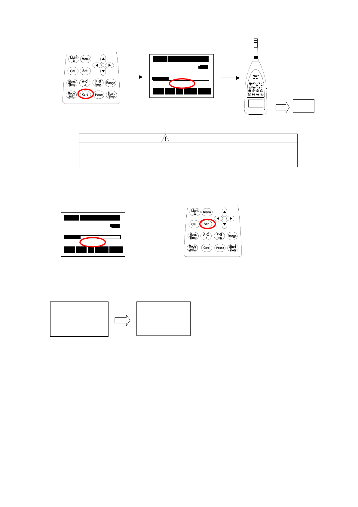
48
Eject the card
C
ard
4400
1
1
3300
4400
1
1
3300
Delete the card data
①Press Card key.
After "STD" lighting, please take out a card in a few minutes.
There is the case that "Card ERR" is displayed. In the case, the file
might be damaged.
00003s
3s 000
000hhhh00
00mmmm00
3s3s
000000
63.5 dB
63.5 dB
63.5 dB63.5 dB
STD
STD
STDSTD
Stp
Stp A
A Fast L
StpStp
A A
00ssss
0000
0000
Fast LA
Fast LFast L
A
AA
① Confirm STD blinking.
Data all Clear
Data all Clear
Data all ClearData all Clear
Yes
Yes====Start
Start
YesYes
StartStart
No
No==== Set
NoNo
Set
SetSet
③Delete all the data along the displayed flow of operation, then to return to the former
window.
00003s
3s 000
3s3s
63.5 dB
63.5 dB
63.5 dB63.5 dB
Stp
Stp A
A Fast L
StpStp
A A
②STD lighted.
SSSSure
ure????
ureure
Yes
Yes====Start
Start
YesYes
StartStart
No
No==== Set
NoNo
Set
SetSet
000hhhh00
00mmmm00
000000
STD
STD
STDSTD
00ssss
0000
0000
Fast LA
Fast LFast L
A
AA
④Eject the Card.
CAUTION
②Keep [Set] key pushed for a few seconds in the
situation with the card installed.
Page 50
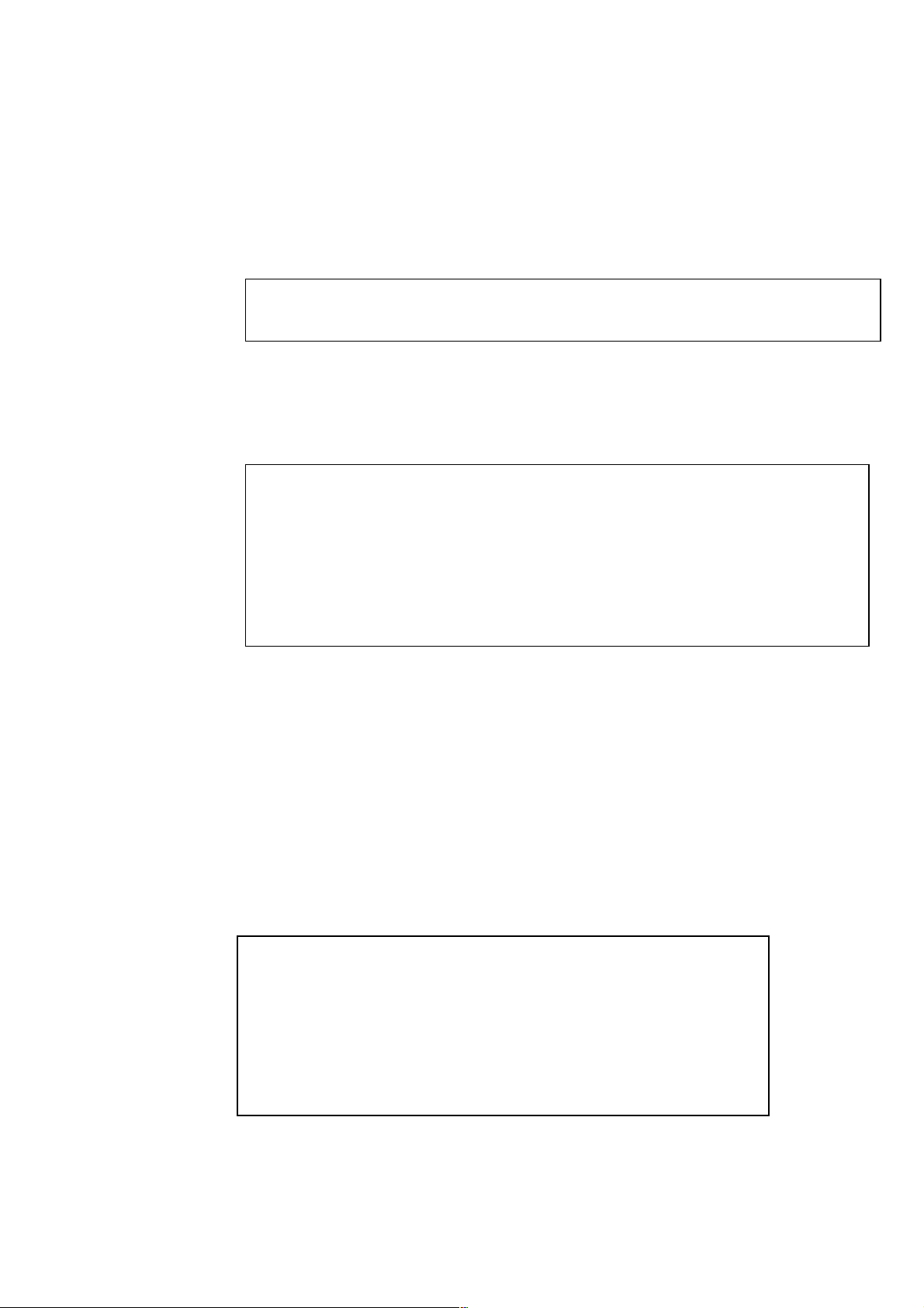
49
Example of file creation
The file is created as follows. :
When A characteristics (Time constant F and S) is selected:
・Single
001.csv ← :Whenever [Start/Stop] key is pushed, this single data line is made. (a single
data since the mode is Single. )
002.csv ↓
・
・
・Repeat
001.csv ← :Whenever [Start/Stop] key is pushed, this data line is made. (two or more
002.csv ↓
・
・
Eventually, in the card, Single and Repeat data files are created at random.
<Example>
001.csv ←:File made in single mode (1 data/ 1file)
002.csv ←:File made in single mode (1 data/ 1file)
003.csv ←:File made in repeat mode (two or more data/file)
004.csv ←:File made in single mode (1 data/ 1file)
005.csv ←:File made in repeat mode (two or more data/file)
・
・
↑ At most 999 CSV files can be made, where [Start/Stop] key is pressed 999 times..
Only LAIeq is made.
Meas…day/Meas…time/Time weight/Level Range/Time sett/LAeq/Lmin……./LA95
2009/03/2 9:54:52 F 80dB 000h…10s 48.9 42.3 43.9
data/file)
Meas…day /Meas…time/Time weight/Level Range/Time sett/LAeq/Lmin……./LA95
2009/03/2 9:54:52 F 80dB 000h…10s 48.9 42.3 43.9
2009/03/2 9:54:52 F 80dB 000h…10s 48.9 42.3 43.9
2009/03/2 9:54:52 F 80dB 000h…10s 48.9 42.3 43.9
・
・<as many data lines as indicated by Repaet>
2009/03/2 9:54:52 F 80dB 000h…10s 48.9 42.3 43.9
Meas…day /Meas…time/Time weight/Level Range/Time sett/LAIeq
2009/03/2 9:54:52 I 80dB 000h…10s 52.3
2009/03/2 9:54:52 I 80dB 000h…10s 52.3
2009/03/2 9:54:52 I 80dB 000h…10s 52.3
・.
<as many data lines as indicated by Repaet>
2009/03/2 9:54:52 I 80dB 000h…10s 52.3
Page 51
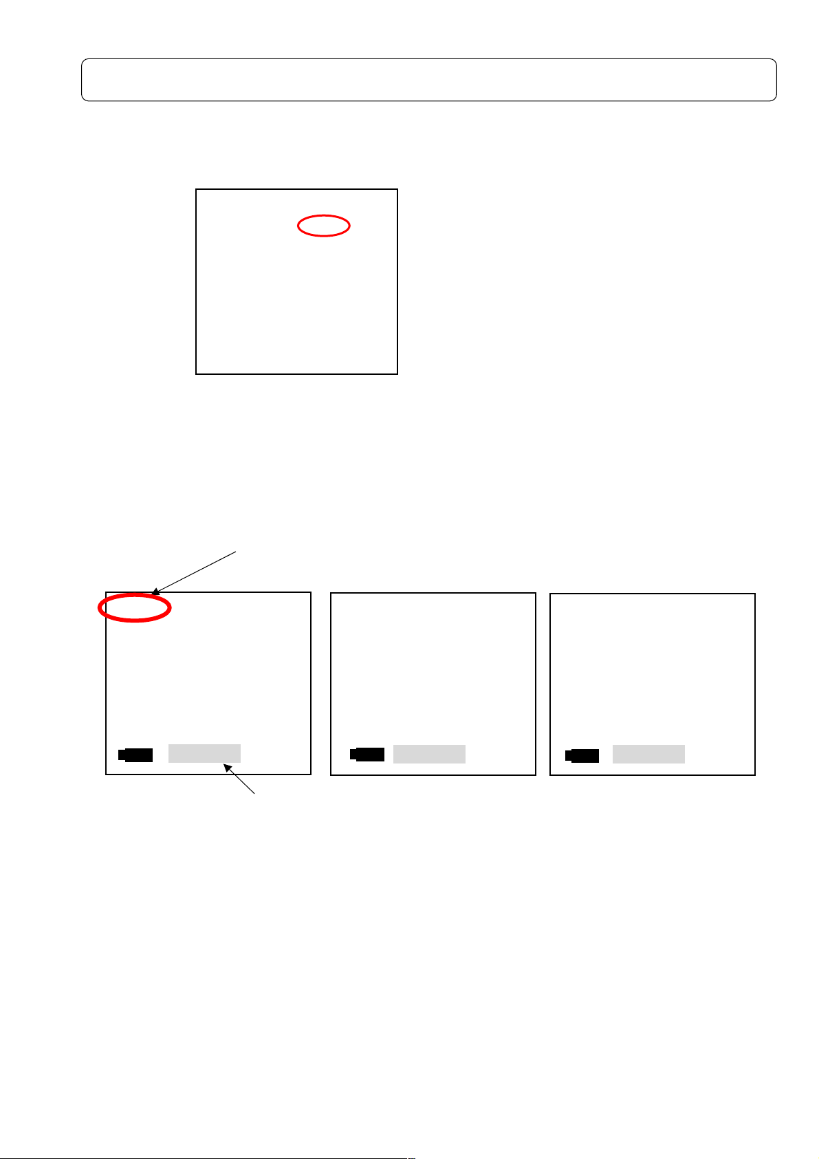
50
Print/Data management
Print
This equipment is provided with a function of printing the measured data with a specified serial
printer.
← Set to
Mode: Print
<Parameter setting>
1) Turn off POWER switch and connect the printer before turning on POWER switch
2) Select Print in [Menu] key, < System > 1/3 screen and press [Set] key.
3) Then, the following screen appears.
<Display>
A-weighting C-weighting Z-weighting
001/014
001/014 10
001/014001/014
FAST
FAST
FAST FAST
LAeq
LAeq:::: 45.3 LA05
LAeqLAeq
LAE
LAE :::: 48.6 LA10
LAE LAE
LA50
Lmin
Lmin:::: 42.2 LA90
LminLmin
Lmax
Lmax:::: 70.5
LmaxLmax
45.3 LA05 ::::***.*
45.3 LA05 45.3 LA05
48.6 LA10 :::: 66.2
48.6 LA10 48.6 LA10
42.2 LA90 ::::***.*
42.2 LA90 42.2 LA90
70.5 LA95
70.5 70.5
<Manner of operation of data>
elect the data with ▲▼key, accelerating by keeping on pushing the cursor.
On pressing [Card] key in the state of Print, it changes to Print Ex and the data in the Card is
displayed
Memory Call IN:Data stored in the internal SRAM.
Print (date communication) starts with the top of the data by pushing the [Start/Stop] key.
Printing can be paused with [Pause] key and restarted by pressing it again from the current
data line. .
The printing is canceled by pressing [Start/Stop] key and stands by at the top data display
screen.
<System>
<System>
<System><System>
Mode
Mode ::::Print
ModeMode
DDDData delet
ata delet ::::off
ata deletata delet
LCD cont
LCD cont :***
LCD contLCD cont
Date
Date y/m/d
y/m/d ::::01/01/01
DateDate
y/m/d y/m/d
Time h/m/s
Time h/m/s ::::00:00:00
Time h/m/sTime h/m/s
Printer(pc)set
Printer(pc)set ::::9600
Printer(pc)set Printer(pc)set
USB out
USB out ::::OFF
USB out USB out
1/3
Print
PrintPrint
off
offoff
:***
:***:***
01/01/01
01/01/0101/01/01
00:00:00
00:00:0000:00:00
9600
96009600
OFF
OFFOFF
1/3
1/31/3
again.
Number of data of memory numbers
10mmmm
1010
Print
Print IN
PrintPrint
08/10/10
08/10/10
08/10/1008/10/10
12:18:20
LA50 ::::***.*
LA50LA50
LA95 ::::***.*
LA95 LA95
IN
IN IN
12:18:20
12:18:2012:18:20
***.*
***.****.*
66.2
66.2 66.2
***.*
***.****.*
***.*
***.****.*
***.*
***.****.*
001/014
001/014 10
001/014001/014
FAST
FAST
FAST FAST
LLLLcccceq
eq
eqeq
LLLLcpeak
cpeak::::71.3
cpeakcpeak
10mmmm
1010
::::63.3
63.3
63.363.3
71.3
71.371.3
Print
Print IN
PrintPrint
08/10/10
12:18:20
IN
IN IN
08/10/10
08/10/1008/10/10
12:18:20
12:18:2012:18:20
001/014
001/014 10
001/014001/014
FAST
FAST
FAST FAST
LLLLpeak
peak::::77772.9
peakpeak
10mmmm
1010
2.9
2.92.9
Print
Print IN
PrintPrint
Display blinks
Memory Call Ex:Date stored in the external Memory card (SD Card)
08/10/10
08/10/10
08/10/1008/10/10
12:18:20
12:18:20
12:18:2012:18:20
IN
IN IN
Page 52
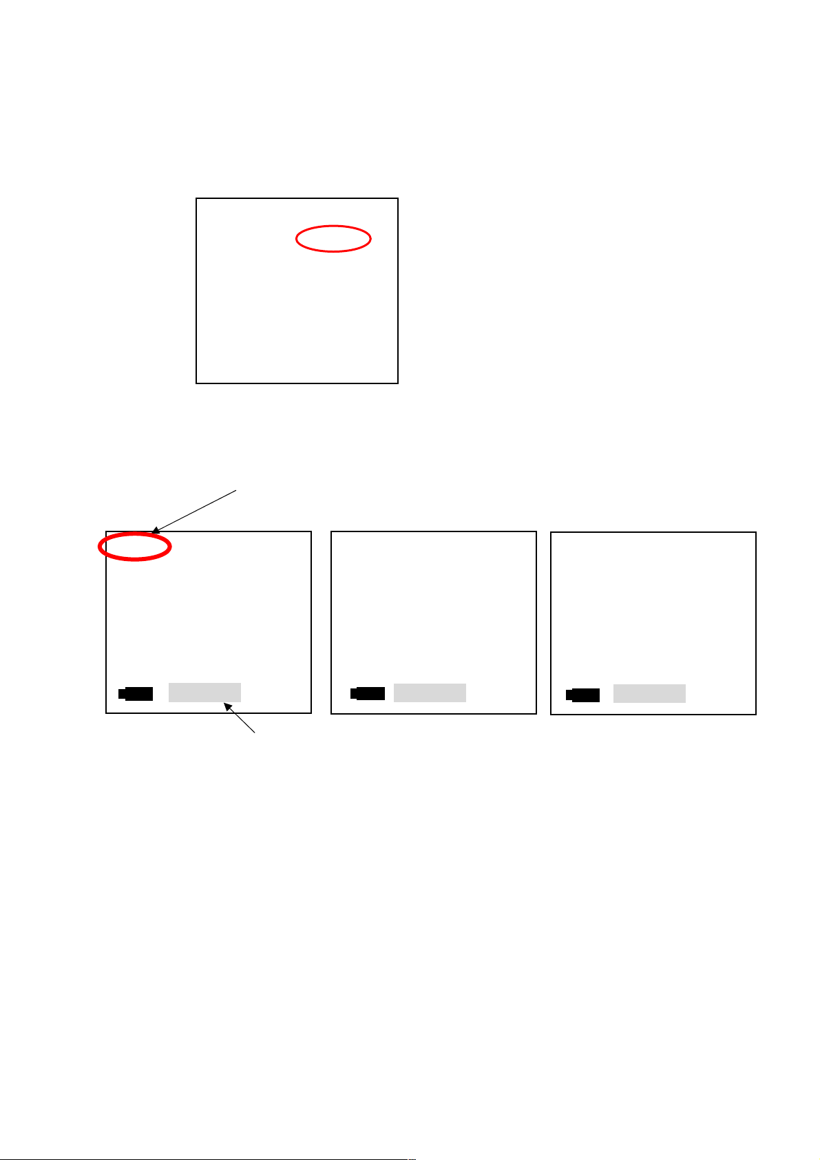
51
Saving Data to PC
This equipment is provided with data saving function using the specified data management
software.
Data management with USB port
← ← Set Mode to PC out display
<Operation>
<Display>
A-weighting C-weighting Z-weighting
001/014
001/014 10
001/014001/014
FAST
FAST
FAST FAST
LAeq
LAeq:::: 45.3 LA05
LAeqLAeq
LAE
LAE :::: 48.6 LA10
LAE LAE
LA50
Lmin
Lmin:::: 42.2 LA90
LminLmin
Lmax
Lmax:::: 70.5 LA95
LmaxLmax
45.3 LA05 ::::***
45.3 LA05 45.3 LA05
48.6 LA10 :::: 66.2
48.6 LA10 48.6 LA10
42.2 LA90 ::::***.*
42.2 LA90 42.2 LA90
70.5 LA95 ::::***.*
70.5 LA95 70.5 LA95
<Manner of operation of data>
Select the data with ▲▼key, accelerating by keeping on pushing the cursor
On pressing [Card] key in the state of Print, it changes to Print Ex and the data in the Card is
displayed
Memory Call IN:Data stored in the internal SRAM.
Date communication starts with the top of the data by pushing [Start/Stop] key.
Printing can be paused with [Pause] key and restarted by pressing it again from the current
data line. .
The printing is canceled by pressing [Start/Stop] key and stands by at the top data display
screen.
<System>
<System>
<System><System>
Mode
Mode ::::PC out
ModeMode
Data delet
Data delet ::::off
Data deletData delet
LCD cont
LCD cont :***
LCD contLCD cont
Date
Date y/m/d
y/m/d ::::01/01/01
DateDate
y/m/d y/m/d
Time
Time h/m/s
h/m/s ::::00:00:00
TimeTime
h/m/s h/m/s
Printer(pc)set
Printer(pc)set::::9600
Printer(pc)setPrinter(pc)set
USB out
USB out ::::OFF
USB out USB out
1/3
PC out
PC outPC out
off
offoff
:***
:***:***
01/01/01
01/01/0101/01/01
00:00:00
00:00:0000:00:00
9600
96009600
OFF
OFFOFF
1/3
1/31/3
Select PC out in [Menu] key, < System > 1/3 screen and press [Set] key.
Number of data of memory numbers
10mmmm
1010
Print
Print IN
PrintPrint
08/10/10
08/10/10
08/10/1008/10/10
12:18:20
LA50 ::::***.*
LA50 LA50
IN
IN IN
12:18:20
12:18:2012:18:20
***.*
******
66.2
66.2 66.2
***.*
***.****.*
***.*
***.****.*
***.*
***.****.*
.*
.*.*
001/014
001/014 10
001/014001/014
FAST
FAST
FAST FAST
LLLLcccceq
eq
eqeq
LLLLcpeak
cpeak::::71.3
cpeakcpeak
10mmmm
1010
::::63.3
63.3
63.363.3
71.3
71.371.3
Print
Print IN
PrintPrint
08/10/10
12:18:20
IN
IN IN
08/10/10
08/10/1008/10/10
12:18:20
12:18:2012:18:20
001/014
001/014 10
001/014001/014
FAST
FAST
FAST FAST
LLLLpeak
peak::::72.9
peakpeak
10mmmm
1010
12:18:20
72.9
72.972.9
Print
Print IN
PrintPrint
Display blinks
Memory Call Ex:Date stored in the external Memory Card (SD_Card)
08/10/10
08/10/10
08/10/1008/10/10
12:18:20
12:18:2012:18:20
IN
IN IN
Page 53
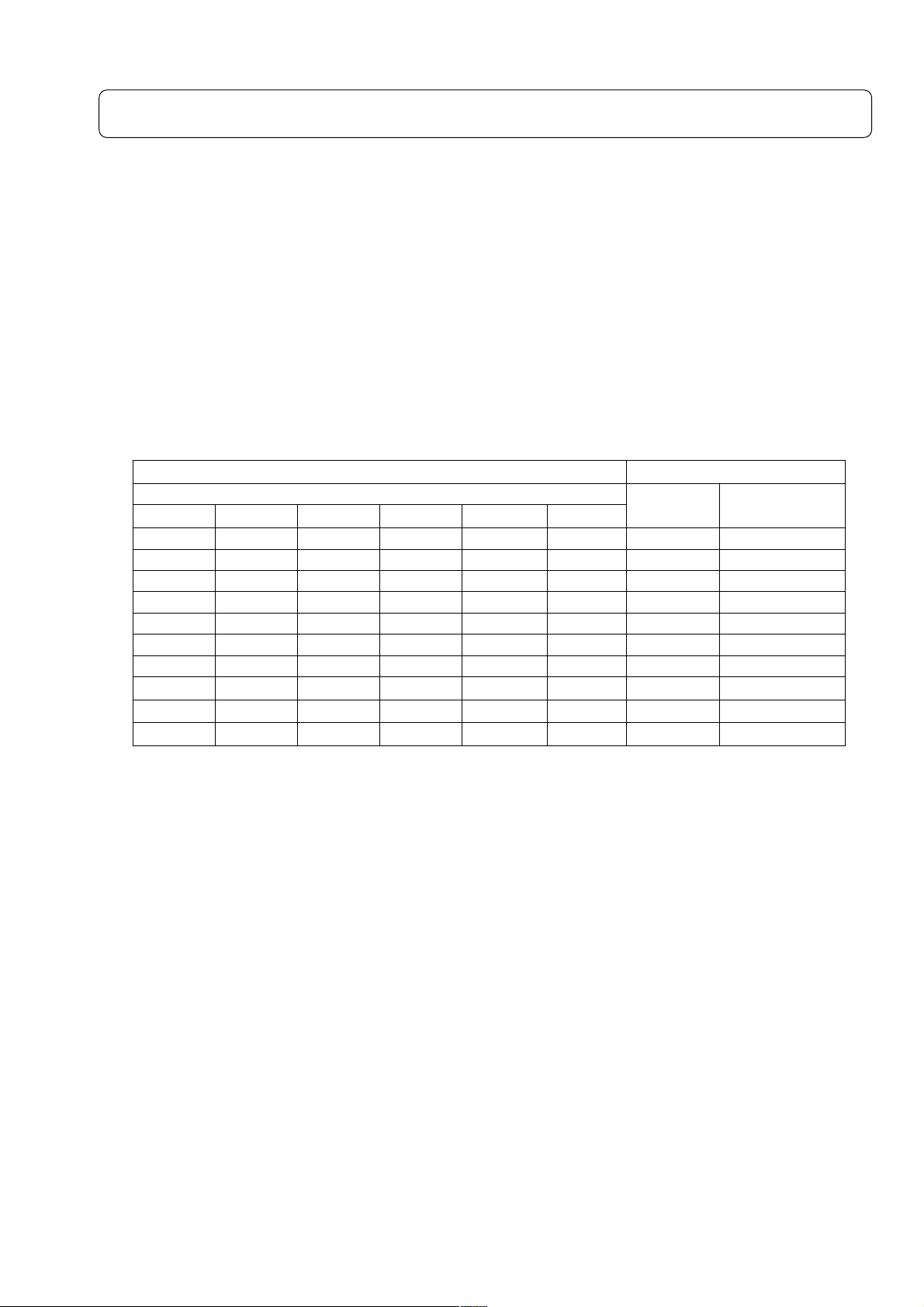
52
Output terminal
AC、、、、DC Output
AC Output
The AC Output is the frequency-weighted signal.
Output: 1Vrms (FS), Output impedance: 600Ω, Load impedance > 10kΩ
DC Output
The DC Output is the frequency-weighted, root-mean-square-detected, and then logarithmic
converted signal.
Output: 2.5V (FS), 0.25V/10dB, Output impedance: 50Ω, Load impedance > 10kΩ
Relation between the display value of each range, and output voltage
DISPLAY VALUE(dB) OUTPUT VOLTAGE(V)
RANGE
40~130 30~120 20~110 20~100 20~90 20~80
130 120 110 100 90 80 1.00000 2.50000
120 110 100 90 80 70 0.31623 2.25000
110 100 90 80 70 60 0.10000 2.00000
100 90 80 70 60 50 0.03162 1.75000
90 80 70 60 50 40 0.01000 1.50000
80 70 60 50 40 30 0.00316 1.25000
70 60 50 40 30 20 0.00100 1.00000
60 50 40 30 20
50 40 30 20
40 30 20
- - -
- -
-
AC OUT
0.00032 0.75000
0.00010 0.50000
0.00003 0.25000
DC OUT
Page 54

53
Specification
1) Type :MODEL 4431
2) Description :Sound Level Meter
3) Applicable Standards :JIS C1509-1:2005 ClassⅡ, IEC 61672-1:2002 Class Ⅱ
4) Frequency Range :20Hz~20kHz(Conforms with measurement law 20Hz~8kHz)
5) Microphone(Sensitivity) :TYPE 7052NR(-33dB, Stand-alone-31dB)
6) Level Range Control :10dB 6step
20~80dB, 20~90dB, 20~100dB, 20~110dB, 30~120dB
40~130dB
7) Measurement Level A :28~130dB
(0~80dB/0-dB measurement function in ON)
C :36~130dB
Z(FLAT) :38~130dB
C peak :55~141dB
Z(FLAT)peak:60~141dB
8) Self-noise level :The lower limit of the measurement range in dB lies 6dB
higher than self-noise level.
9) Linearity Range :100dB
10) Time weighting :Fast、Slow、Impulse
11) Frequency weighting :A, C, Z(FLAT)
12) Measurement items :Sound pressure level(Lp), A-weighted sound pressure level,
C-weighted sound pressure level(LA, LC),Equivalent
continuous A-weighted sound pressure level(L
exposure level(LAE), Maximum sound pressure level(L
Minimum sound pressure level(L
), Percentile sound
Amin
pressure level(5 freely selectable values, LAN), Peak sound
pressure level(L
(L
level(L
), C-weighted equivalent continuous sound pressure
Cpeak
)
Ceq
), C-weighted peak sound pressure level
peak
Power average of maximum sound pressure level in a
given interval(L
), Impulse sound pressure level(LAI),
Atm5
Impulse equivalent continuous sound pressure level(L
13)Measurement time :1s, 3s, 5s, 10s, 1mim, 5mim, 10mim, 15mim, 30mim,
1h, 8h, 12h, 24h, Manual(Max. 199h59m59s)
14) Sampling Time :20.8μS(Leq、L
max、Lmin
), 100ms(LN )
15) Data clear function :Pause, and a function that deletes preceding 3 or 5 sec. data.
Memory start ;Selectable Auto or Manual
16) Timer function :A marker can be set to start and stop the measurement at any
specified moments.
17) Display :Liquid crystal and Backlight(128×64 points)
Display range :4digits display
Display cycle :display Period: 1s
Bar display :display Period: 0.1s
Warning :Over ;+3dB from upper limited scale
Under;-0.6dB from lower limited scale
Battery display :5 steps display
Date :year/month/day/ hour:minute:second
), Sound
Aeq
Amax
AIeq
),
)
Page 55

54
18) Calibration signal :Electric calibration with internal oscillator
(1kHz sine wave)
19) Outputs AC output :φ2.5 Jack
Output :1Vrms (FS)
Output impedance:600Ω
Load impedance :more than 10kΩ
DC output :φ2.5 Jack
Output :2.5V (FS), 0.25V/10dB,
Output impedance :50Ω
Load impedance :more than 10kΩ
20) RMS detection circuit :True RMS detection circuit (computing type)
21) Processing :Digital
22) Pause :Normal pause function, as well as the function of
canceling the data before pausing the measurement,
are available.
23) Data Storage Functions :Sound pressure level or Processed values stored
in built-in Memory or Memory card
Manual Storage :Sound level, Calculation value, Memory time,
Store the Sampling Time to Built-in memory or
on Memory card
Auto Storage :Sampling interval 100ms, 200ms, sound level , Leq etc.
Processing Card :Storage of calculation results
24) I/O :Direct output to printer, control and output data to
computer
Digital output of real-time noise waveform with
USB interface
25) Comparator Output :Comparator Function with threshold level
26) Battery Type :Four 1.5V Alkaline cells IEC type LR6,
Optional AC adapter
Battery life :Alkaline dry cell ; Approx.9 hours
when Switch on a back light ;
Approx.1/3
Consumption current :Approx.150mA (When input 6V) at Calcutation OFF.
When AC adaptor is used ;Approx.2.6VA
27) Operating temperature :-10~50℃ 30%~90%RH(no condensation)
28) Size :86(W)×285(H)×46(D)
29) Weight :Less than Approx.450g (Including batteries)
30) Option
・1/1 and 1/3-octave Real-time Analysis Card
Applicable standards :JIS C 1514(IEC61260):Class1
Measurement mode :Sound pressure level (Lp), Equivalent continuous
Sound pressure level (Leq), Sound exposure level(LE),
Maximum sound pressure level (Lmax)
(One of the measurement modes selected as above is
displayed.)
Page 56

55
Frequency analysis band :1/1- octave filter;16Hz, 31.5 Hz, 63 Hz, 125 Hz, 250 Hz,
500Hz, 1kHz, 2kHz,4kHz, 8kHz, AP
1/3- octave filter;12.5Hz, 16Hz, 20 Hz,25 Hz,31.5Hz,40Hz,
50Hz, 63Hz, 80Hz, 100Hz, 125Hz, 160Hz,
200Hz, 250Hz, 315Hz, 400Hz, 500Hz,
630Hz, 800Hz, 1kHz, 1.25kHz, 1.6kHz,
2kHz, 2.5kHz, 3.15kHz, 4kHz, 5kHz,
6.3kHz,8kHz,10kHz ,12.5kHz, 16kHz, AP
・FFT Analysis Card
Frequency span :2kHz、5kHz、10kHz、20kHz
Time window :Rectangular、Hanning
Analysis line :400
Zoom :×1, ×2, ×4
Processing :Sound pressure level, Linear average value, Max,
・RSR card (Real sound recording card)
This card enables automatic recording with specified level and time, namely adding
the function of recording real wave data.
The data is recorded in WAVE file format (48kHz 16bit Mono), easily corresponding to
most common application software of acoustic analysis, as well as displaying its greatest
force in all kinds of acoustic analysis.
Time for continuous record:Approx.6 hours
Page 57
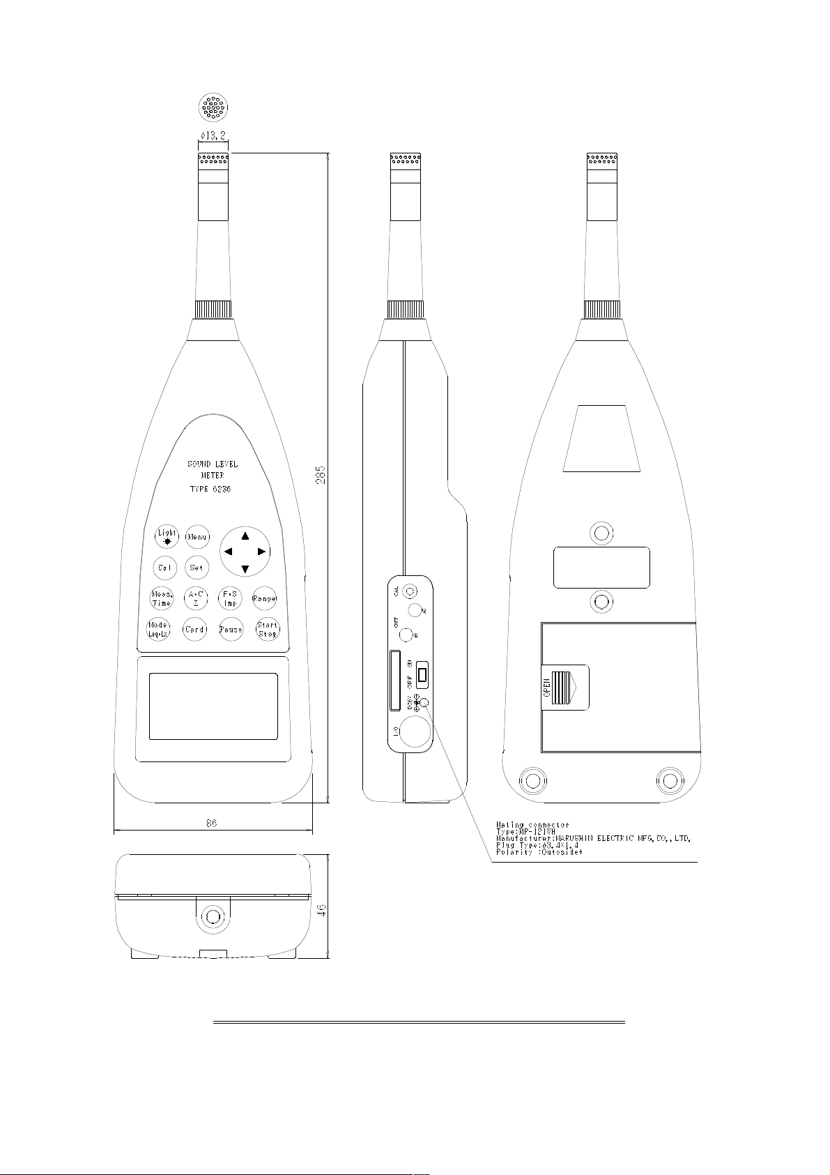
56
Appearance diagram of Sound Level Meter MODEL 4431
Page 58
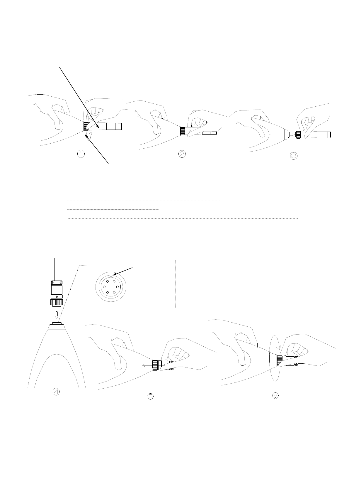
57
Pin Connections and How to Connect the Extension cable
1) Detach microphone from the body of the meter.
Microphone
① Turn the threaded reraining ring a little to the left.
② Pull out microphone as shown.
③ Repeat ① turn a left and ② pull out a little 5-8 times and you can separate.
2) Then plug the male connector of extension cable into the connector of the body.
④Mach key groove of body’s connector with the connector of extension cable and
insert.
⑤Push the connector of extension cable.
⑥Turn the threaded reraining ring a little as shown repeat ⑤ and ⑥ 5-8 times
and you can connect.
The threaded reraining ring
Mach key
Page 59
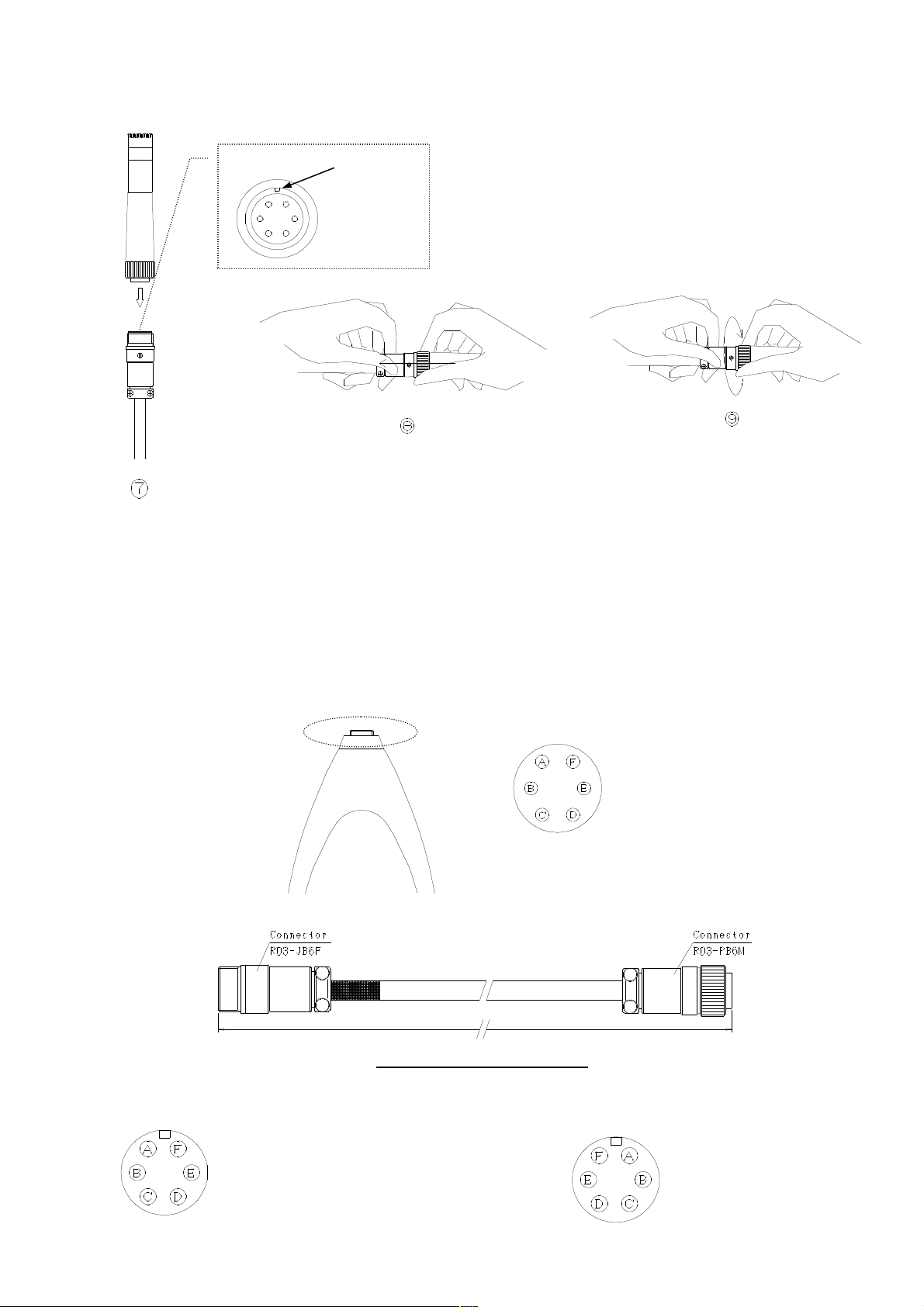
58
3) Attach microphone to the female connector of extension cable.
Mach key
⑦Mach key groove of body’s connector with the connector of extension cable and
insert.
⑧Push the connector of extension cable.
⑨Turn the threaded reraining ring a little as shown repeat ⑧ and ⑨ 5-8 times
and you can connect.
※ Note; Do not turn only the threaded reraining ring connecting.
It causes damage to the connector.
【Wiring diagram of Main body side connector】
Connector (Soket;Type R03-R6F)
【Wiring diagram of Extension cable】
A;+6.5V E;NC
B;NC F;SIG
C;-6.5V
D;GND
Connector (Pin;R03-JB6F)
A;+V D;COM
B;NC E;NC
C;-V F;SIG
Extension cable(2m~30m)
Connector (Soket;R03-PB6M)
A;+V E;NC
B;NC F;SIG
C;-V
D;COM, Shield
Page 60
59
Communication Command
CMD
DAT
CR LF
Data
Variable size
ASCII
Command
1byte
ASCII
Interface
USB: LSI FT245
Transfer Speed :9600~921600bps
Data size :8bit
Stop bit :1bit
Parity check :non
RS-232C:
Transfer Speed :9600,19200,38400bps
Data size :8bit
Stop bit :1bit
Parity check :non
Format
:
:
(
(
)
)
Page 61
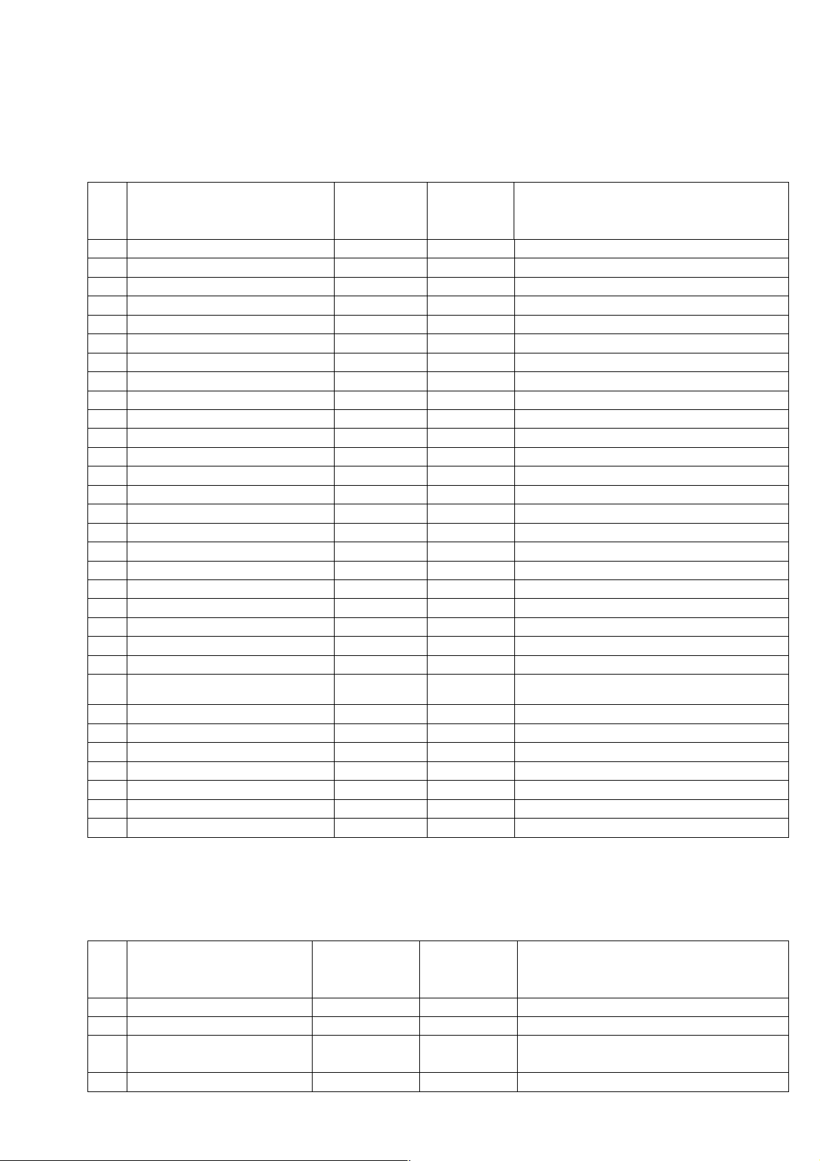
60
Command table((((CMD))))
Capital letters pertain to PC command Small letters paertain to 4431 command
Normal Command::::Nomal Sound Level Meter MODE
4431
№
Function Item
↑
PC
Time and date setting request
1
Time and date setting completed
Configuration file transfer
2
Configuration file completed
Set confirmation
3
Set forwarding
Start measurement
4
Start measurement
Stop measurement
5
Stop measurement
Data acquisition compreted
6
Data request
7
Data transfer
Calibration
8
Back light
9
Independent range setting
10
Filter setting
11
Lp-value acquisition
12
Latm5 Start command
13
LAleq Start command
14
Wave data exhaust command
15
Version acquisition
16
T
t
F
f
I
DATA
S
s
E
e
r
D
DATA
C
c
L
l
R
r
A
a
P
M
m
Q
q
W
DATA
V
DATA
【【【【Option】】】】
Filter command::::When Filter card is installed, An additional receipt is done by a usual sound level
meter command.
4431
№
Function Item
↑
PC
1 Filter mode O Filter mode setting
o
LB Exhausting special
2
command
B
LB exhaust DATA
PC
↑
4431
PC
↑
4431
Function Outline
Calendar registration
Measurement condition setting
Set reading
Set content collection
Measurement beginning command
Measurement stop command
Data has been secured
Data request command
Acquisition data collection
Calibration mode command
Only the display
LED lighting command
The return is not only in specification.
The return is not only in specification.
Data transfer
Beginning of power value at the maximum
noise level in section
Beginning of impulse equivalent noise level
Wave data exhaust beginning(USB Only)
Function Outline
Filter ber data exhaust beginning
(USB Only)
Page 62
61
【【【【Option】】】】
FFT Command::::When FFT card is installed、、、、An additional receipt is done by a usual sound level
meter command.
№
Function Item
4431
↑
PC
PC
↑
4431
Function Outline
1 Frequency span G Frequency span setting
g
2 Maes Time H Measurement time
h
3 Window function J Window function setting
j
4 Mode K Addition average or MAX
k
5 Filter Lp-value acquisition N
(USB Only)
DATA
Page 63
62
Detail of Command
and data
Normal Command::::Nomal Sound Level Meter MODE
CMD
T
t
F Transfer
f
I
Set forwarding
S Start measurement
s Start measurement
E Stop measurement
e
r Data acquisition
D
C CAL
Operation
L
Operation
R
Opration
A Filter specification
P
M Latm5 start Data division note
m Data acquisition after “r” command is received
Q LAleq start Data division note
q Measurement start Data acquisition after “r” command is received
Function Item Data Item Function Outline
Time
setting request
Time and data
setting completed
configuration file
Set confirmation
command
Data request
Data transfer
Data request
Range single
specification
Lp-value
acquisition
Data transfer ASCII(5)
ASCII(13)
ASCII(5) A B C D E
ASCII(5) Conforming of configuration file
ASCII(*)
ASCII(1)
ASCII(1)
YYMMDDHHMMSS
Data division note
A :Meas Time select(1)
0 ;*** 1 ;1s 2 ;3s
3 ;5s 4 ;10s 5 ;1m
6 ;5m 7 ;10m 8 ;15m
9 ;30m A ;1h B ;8h
C ;12h D ;24h
B :Range setting(1)
0 ;130dB 1 ;120dB
2 ;110dB 3 ;100dB
4 ; 90dB 5 ;80dB
C :Filter setting(1)
0 ;A 1 ;C 2 ;F
D :Time constant(1)
0 ;FAST 1 ;Slow 2 ;Imp
E :Interval(1)
0 ;single 1 ;repeat
Data division note
Data division note
Data division note
Data division note
Data division note
Data division note
Data division note
CAL ( It stop again by C or E )
Data division note
It turns it off by E
0:130 1:120・・・・・5:80
Data division note
0:A 1:C 2:F
Data division note
Data division note
Page 64
63
V Version request Data division note
Data transfer
W Wave out request Data division note
Data transfer
【【【【Option】】】】
Filter command::::At Filter Card setting, it is usually added to a Sound level meter command
CMD
O Filter setting ASCII(1)
o Data division note
B LB exhaust command
Data transfer
【【【【Option】】】】
FFT command::::At Filter Card setting, it is usually added to a Sound level meter command
CMD
G Frequency span ASCII(1)
g Data division note
H Mease Time
h Data division note
J Window function
j Data division note
K FFT Mode
k Data division note
N FFT Lp-value Data division note
n
Function Item Data Item Function Lutline
0:1/1 1:1/3
Data division note It stops again by E
ASCII(*)
Function Item Data Item Function Lutline
ASCII(3)
ASCII(1)
ASCII(1)
ASCII(*)
0:20kHz 1:10kHz 2:5kHz 3:2kHz
001~999
0:Mann 1:Rect
0:LIN 1:MAX
Page 65
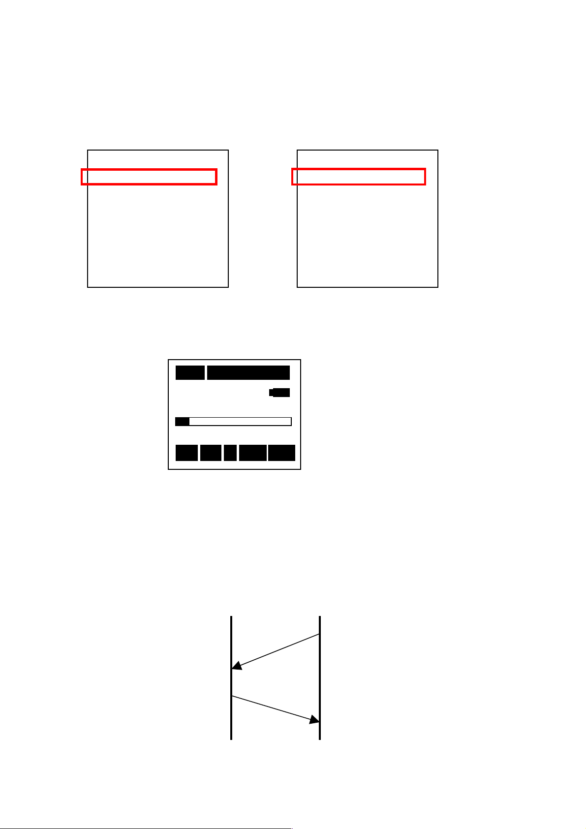
64
4431
PC
Various Command
Data and Answer
Waitin Command
Preparation((((To Remote Mode))))
1. Main body side setting and screen
Select Renote Mode manually.
<USB Communicate> <RS-232C Communicate>
<System>
<System>
<System><System>
Mode
Mode ::::Remote
ModeMode
Data delet
Data delet ::::off
Data deletData delet
LCD cont
LCD cont :***
LCD contLCD cont
Date
Date y/m/d
y/m/d ::::01/01/01
DateDate
Nest time you power on, it stars with [Remote].
To cancel it, select [Menu] in Menu.
2. Communication timing
y/m/d y/m/d
Time
Time h/m/s
h/m/s ::::00:00:00
TimeTime
h/m/s h/m/s
Printer(
Printer(PC
Printer(Printer(
USB out
USB out ::::OFF
USB out USB out
PC)set
)set ::::9600
PCPC
)set )set
1/3
Remote U
RemoteRemote
off
offoff
:***
:***:***
01/01/01
01/01/0101/01/01
00:00:00
00:00:0000:00:00
9600
96009600
OFF
OFFOFF
【Normal Screen】
10
10mmmm 000
1010
63.5 dB
Stp
Stp
StpStp
1/3
1/31/3
U
U U
000hhhh00
000000
63.5 dB
63.5 dB63.5 dB
Remote
Remote
60
60
6060
After Power ON
RemoteRemote
130
Z
Z Fast
Z Z
00mmmm05
05ssss
0000
0505
130
130 130
Fast Lp
Fast Fast
Lp
Lp Lp
<System>
<System>
<System><System>
Mode
Mode ::::Remote
ModeMode
Data delet
Data delet ::::off
Data deletData delet
LCD cont
LCD cont :***
LCD contLCD cont
Date
Date y/m/d
y/m/d ::::01/01/01
DateDate
y/m/d y/m/d
Time
Time h/m/s
h/m/s ::::00:00:00
TimeTime
h/m/s h/m/s
Remote
Remote((((PC
RemoteRemote
USB out
USB out ::::OFF
USB out USB out
PC)set
)set ::::9600
PCPC
)set )set
※Display changes int [Remote]
Inhibiting any other key access than
Memu.
1/3
Remote R
RemoteRemote
off
offoff
:***
:***:***
01/01/01
01/01/0101/01/01
00:00:00
00:00:0000:00:00
9600
96009600
OFF
OFFOFF
1/3
1/31/3
R
R R
 Loading...