

Page 1
1.Overview
PARTICLE COUNTER SOFTWARE
For Part11
Operation Manual
0
Please keep this operation manual handy for future reference.
02002
12.04
Page 2

1.Overview
1
* The operation manual is stored in Adobe PDF format, which can be read by Adobe Acrobat 4.x or higher.
* Windows 9x/NT/2000/XP/Vista/7 is a registered trademark of Microsoft Corporation.
* The unauthorized use or duplication, either whole or in part, of this Software or its Operation Manual is
strictly forbidden.
* The contents of this Operat ion Manual are subject to change for quality improvement without notice.
Page 3
1.Overview
2
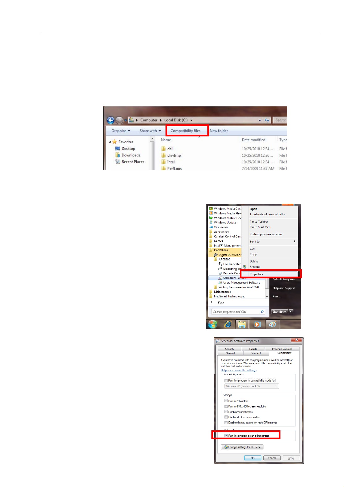
Precautions When Using Kanomax Software Products on Windows 7
Stored data may not appear in Windows Explorer if you had saved data in the C:/ folder or the folders und er the
Program Files (Program Files(x86) for 64 bit).
Click “Compatibility files” in Windows Explorer to display the data.
If you can not perform this operation, or “Compatibility files” does not appear, you need to save data in the folder
such as “My Document” which users can read or write.
When using the A irborne Particle Cou nter Software, you nee d to configure the settings for Scheduler Software.
Otherwise, schedule data will not appear and can not be transferred when using the File Transfer Software to
transfer schedule.
Click [Start] -> [(All) Programs] -> [KANOMAX].
Right-click [Scheduler Software] and click [Properties].
Click the “Compatibility” tab in the “Scheduler Software Properties”
window.
Check “Run this program as an administrator” in Privilege Level.
Click [OK] to close the window.
Page 4

1.Overview
Table of Contents
1. Overview..............................................................................................................5
1.1. Packing List............................................................................................................................5
1.2. System Overview ...................................................................................................................5
2. Installation .......................................................................................................... 6
2.1. Installation..............................................................................................................................6
2.2. Starting and Closing a Program..............................................................................................6
2.3. Uninstalling............................................................................................................................7
3. Remote Console Software.................................................................................. 8
3.1. Main Screen............................................................................................................................8
3.2. Menu List ...............................................................................................................................9
3.3. Destination Settings and Command Buttons.......................................................................... 9
3.4. How to Operate the Remote Console Software ...................................................................10
3.5. Search Function....................................................................................................................11
3
4. Scheduler Software...........................................................................................12
4.1. Main Screen..........................................................................................................................12
4.2. Menu List .............................................................................................................................12
4.3. Command Buttons................................................................................................................13
4.4. Schedule File Creation.........................................................................................................14
4.4.1. Creating a new file ...........................................................................................................................14
4.4.2. Editing an existing file .....................................................................................................................15
5. File Transfer Software .....................................................................................16
5.1. Main Screen..........................................................................................................................16
5.2. Menu List .............................................................................................................................16
5.3. Destination Settings and Command Button.........................................................................17
5.4. Downloading Measurement Data.........................................................................................19
5.5. Uploading a Schedule File ...................................................................................................20
5.6 Search Function....................................................................................................................21
6. Measuring Software......................................................................................... 22
6.1. Operation Overview ...........................................................................................................22
6.2. Screen Structure ...................................................................................................................23
6.3. Data File...............................................................................................................................24
6.3.1. File Menu........................................................................................................................................24
6.3.2. Data File List....................................................................................................................................24
6.4. Settings.................................................................................................................................25
6.4.1. LAN Settings..................................................................................................................................25
6.4.2. Measurement Parameter Settings....................................................................................................25
6.5. Remote Measurement...........................................................................................................26
6.5.1. Start/End Measurement....................................................................................................................26
6.5.2. Measurement....................................................................................................................................27
6.5.3. Measurement Data Storage...............................................................................................................27
6.6. Remote Measurement Data Display.....................................................................................28
6.6.1. Data Display Format ........................................................................................................................28
Page 5

1.Overview
6.6.2. Particle Graph...................................................................................................................................28
6.6.3. Temperature, Humidity, Air Velocity and Differential Pressure Graph............................................30
6.6.4. Data T able.........................................................................................................................................31
6.7. Other Functions....................................................................................................................32
6.7.1. Switching Languages .......................................................................................................................32
6.7.2. Windows Arrange.............................................................................................................................32
6.7.3. Software Version ..............................................................................................................................32
6.7.4. Printing Function..............................................................................................................................33
7. User Management Software............................................................................34
7.1. When You First Start Software.............................................................................................34
7.1.1. Start Screen.......................................................................................................................................34
7.1.2. Specifying Data Storage Folder and SD(MMC) Card Drive Name.................................................34
7.1.3. Registering a New Local User..........................................................................................................35
7.2. Starting Software After Registering Local Users.................................................................36
7.2.1. Starting Software..............................................................................................................................36
7.2.2. Download Button .............................................................................................................................38
7.2.3. Decrypt Button.................................................................................................................................40
7.2.4. Approval1/Approval2 Button...........................................................................................................41
7.2.5. User Management [3910 Online].....................................................................................................41
7.2.6. User Management [3910 SD Card]..................................................................................................47
7.2.7. User Management [Local]................................................................................................................48
4
8. Miscellaneous Notes ......................................................................................... 51
Page 6

1.Overview
1. Overview
1.1. Packing List
The following item is included in this package:
QTY
1. AIRBORNE PARTICLE COUNTER SOFTWARE CD-ROM 1
If the CD-ROM is missing or damaged, please contact your local distributor immediately.
1.2. System Overview
5
This software package includes four programs as follows;
- Remote Console Software
- Scheduler Software
- File Transfer Software
- Measuring Software
- User Management Software
Use the Remote Console Software to operate the Airborne Particle Counter remotely via computer.
Use the Scheduler Software to create a schedule file for use when performing a measurement.
Use the File Transfer Software to download stored measurement data from or upload a schedule file to the
Airborne Particle Counter.
Use the Measuring Software to collect particle, air velocity, humidity and differential pressure data from the
Airborne Particle Counter.
Use the User Management Software to manage users, measurement data, and log data in the instrument.
Applicable Computer Requirements:
Model: IBM PC compatible
Ethernet Connector: 1 available Ethernet port
OS English or Japanese Windows XP SP2 or higher, Windows Vista SP1 or higher,
Windows 7, .NET Framework 3.5 or higher
Network Requirements:
Your Firewall and/or Network Router settings may limit your Network connectivity while using this
software. If you experience connectivity issues, please configure the following settings:
- When using the Remote Console Software or the Measuring Software, open TCP ports “12344” and
“12346.
- When using the Search Software, open UDP port “12345”, and ensure broadcasting is available on the
network.
- When using the File Transfer Software, open FTP port “21”.
Please refer to your Firewall or Router operation manual.
If you have any questions regarding the settings or network, please contact your network administrator.
Page 7

2. Installation
2. Installation
2.1. Installation
When installing the software, be sure to log in with a user that has administrative rights and follow the
procedure below.
Insert the product CD-ROM into the CD-ROM drive.
This operation can be started from the Windows Explore menu.
(1) Using Windows Explorer, find and double-click the setup.exe file located in the “English” folder
on the product CD-ROM.
(2) Follow the instructions displayed on the screen.
(3) When the installation is completed successfully, a “KANOMAX” folder will be added to the
“(All) Programs” list in the “Start” menu.
6
2.2. Starting and Closing a Program
To Start the PARTICLE COUNTER Remote Console Software:
From the start menu, click: [(All) Programs] -> [KANOMAX] -> [LPC3910]-> [Remote Console
Software].
The main window of the software will be displayed.
To Start the PARTICLE COUNTER Scheduler Software:
From the start menu, click: [(All) Programs] -> [KANOMAX] -> [LPC3910]-> [Scheduler Software].
The main window of the software will be displayed.
To Start the PARTICLE COUNTER File Transfer Software:
From the start menu, click: [(All) Programs] -> [KANOMAX] -> [LPC3910]-> [File Transfer software].
The main window of the software will be displayed.
To Start the PARTICLE COUNTER Measuring Software:
From the start menu, click: [(All) Programs] -> [KANOMAX] -> [LPC3910]-> [Measuring Software].
The main window of the software will be displayed.
To Start the PARTICLE COUNTER User Management Software:
From the start menu, click: [(All) Programs] -> [KANOMAX] -> [LPC3910]-> [User Management
Software].
The main window of the software will be displayed
To close the software:
- From the [File] menu, select [Exit], or
- Click the [x] button located at the right end of the title bar of the main window.
Page 8

2. Installation
2.3. Uninstalling
(1) Open [My Computer] -> [Control Panel] -> [Add or Remove Programs].
(2) Select [PARTICLE COUNTER Software] from the list, and click [Remove].
7
Page 9
3. Remote Console Software
3. Remote Console Software
Use the Remote Console Software to operate the Particle Counter remotely via computer.
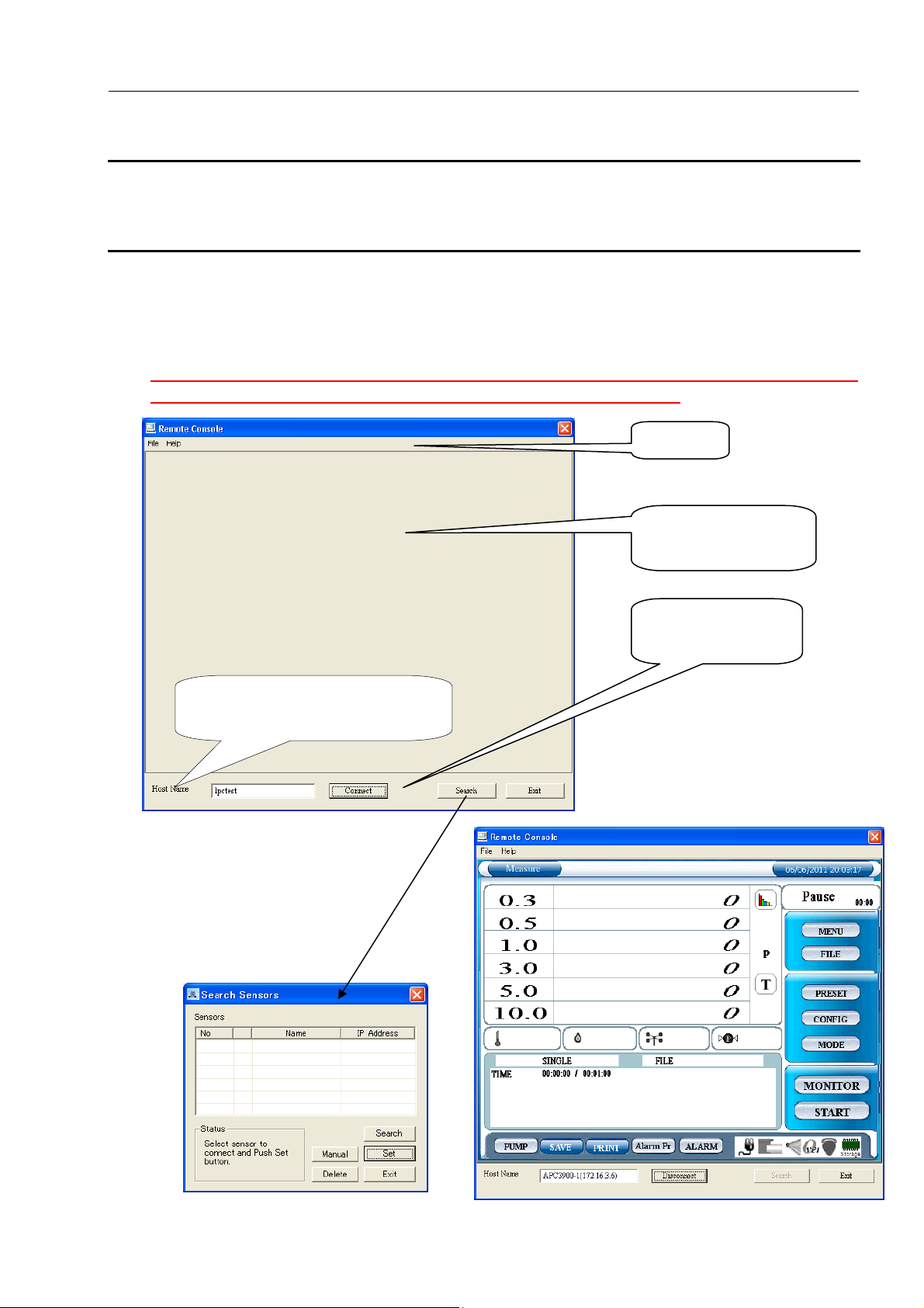
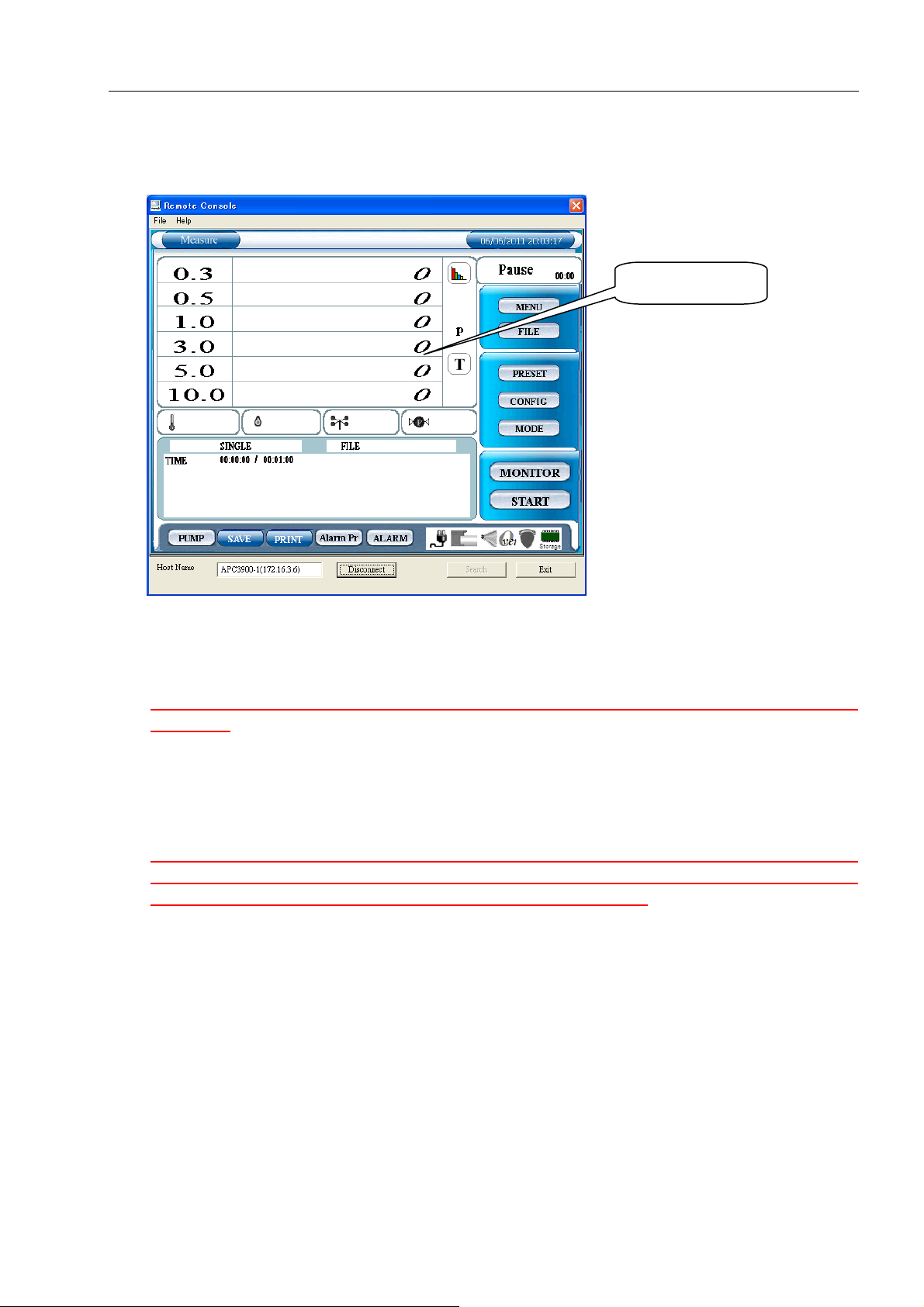
3.1. Main Screen
Both the PC running the software and the Particle Counter must be connected to the LAN and
properly configured in order to access the Particle Counter remotely via PC.
Refer to “3.3.Destination Settings
and Command Buttons”
Menu Bar
Remote Screen will be
displayed here.
Connection Settings,
Connect Buttons etc.
8
Page 10
3. Remote Console Software
3.2. Menu List
File Menu
[Exit] Closes the software.
Help Menu
[About] Views the software version information.
3.3. Destination Settings and Command Buttons
(Refer to 3.1. Main Screen.)
Host Name
Enter the Host Name for the instrument you wish to connect with. The instrument’s Host Name is
configured in the instrument’s COMMUNICATION SETTING.
You can also choose a Host Name by using [Search] which will display all the instruments currently
connected to the LAN (Refer to 3.5. Search Function
Connect
Click [Connect] to connect to the instrument config ured in Host Name.
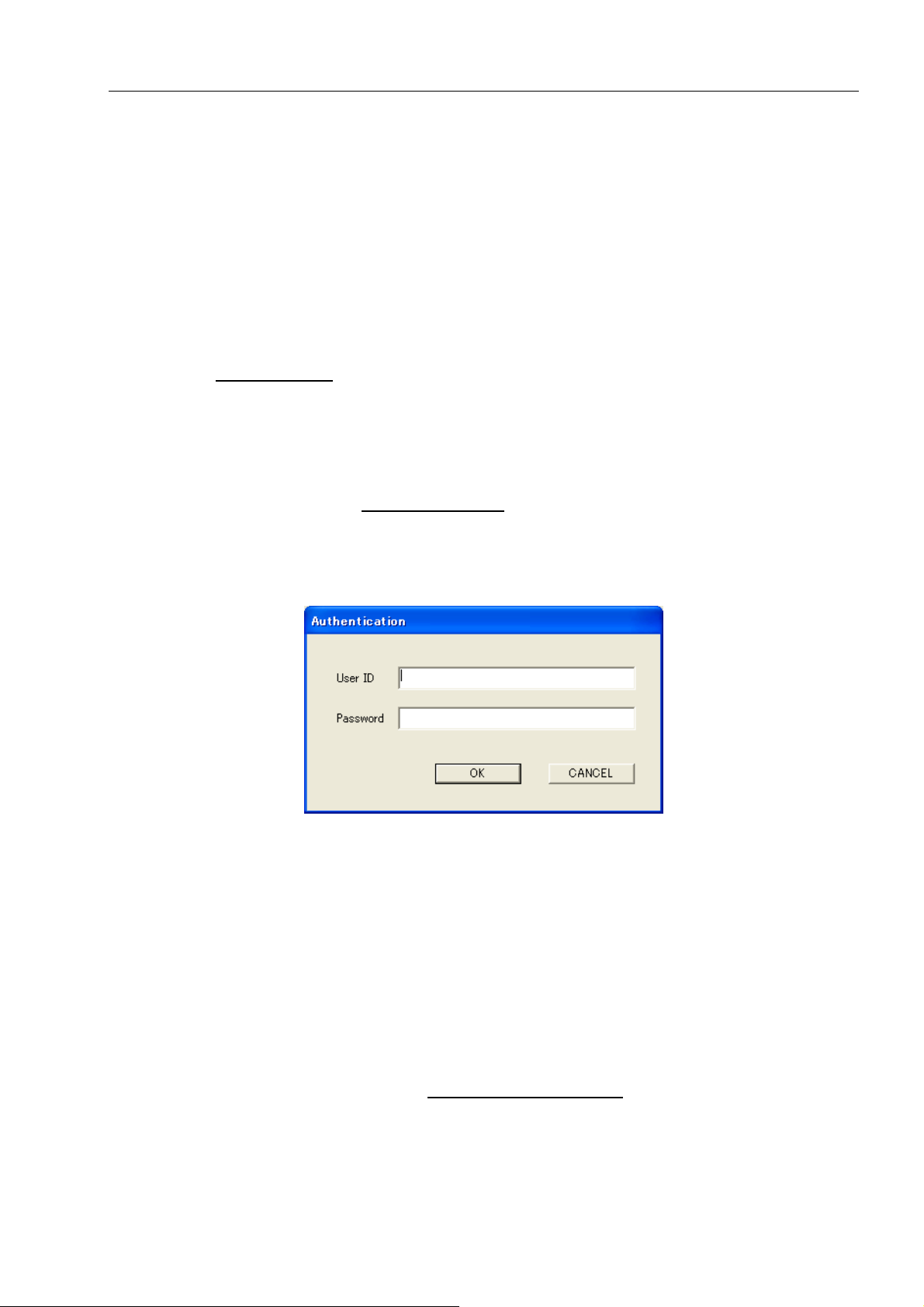
The “Authentication” window will be displayed, prompting you to enter your User ID and Password.
Enter your User ID and Password that that you use to log into the instrument and click [OK]. If the
authentication succeeds, the connection will be established.
NOTE: In order to access the instrument remotely the user mu st have [Administrator] or [Remote Control]
rights. Also, the instrument cannot be accessed remotely via PC if it is remote mode.
If the connection fails, a message will be displayed saying “The connection was ended because of a network
error.”
To reconnect to the instrument, click [Connect].
If the connection succeeds, the instrument screen will be displayed, and the [Connect] button will be
replaced by the [Disconnect] button.
Search
Starts a search for connected instruments (Refer to 3.5 Search Function
EXIT
Closes the software.
).
).
9
Page 11
3. Remote Console Software
3.4. How to Operate the Remote Console Software
.
After the computer is successfully connected to the instrument, the instrument screen will be displayed on
the computer.
Click the buttons on the display to operate the instrument as described in the instrument’s instruction
manual.
Due to LAN communication lag, there may be a slight delay before the instrument reacts to your
commands.
If the computer becomes unresponsive for a minute or longer, it may be disconnected or a problem
may have occurred with the LAN communications. If that is the case, close the software by clicking
[Exit]. Check the LAN communications and restart the software.
NOTE: If the instrument is put in remote mode while you are using the “Remote Console Software”,
communications between the instrument and PC will be terminated. The instrument should only be
placed in remote mode when using the “Measuring Software” program.
Operation Screen
10
Page 12

3. Remote Console Software
3.5. Search Function
Click [Search] to find instruments connected to the LAN.
Click [Search]
If a connected instrument is found, it will be listed in the “Search Sensors” window shown above.
Select the instrument that you want to connect with and click [Set]. The name of the instrument select ed will
be displayed on the Remote Console Software,File Transfer Software or User Management Software.
If you know the Host Name and the IP address of an instrument,
click [Manual] to open the dialog box shown on the right.
Enter the Host Name and IP address of the instrument,
and click [OK].
The instrument will be added to the “Search Sensors” window
and an “m” will appear to the left of the Host Name,
as shown below.
To delete Host Name and IP Address which were manually
input, select the instrument that you want to delete and click
[Delete].
[Manual] and [Delete] are disabled while searching. To enable
[Manual] and [Delete], click [Stop] to finish searching.
Click [Exit] to close the search function and return to the previous screen.
11
Page 13
4. Scheduler Software
4. Scheduler Software
Use the Scheduler Software to create a schedule file for use when performing a measurement.
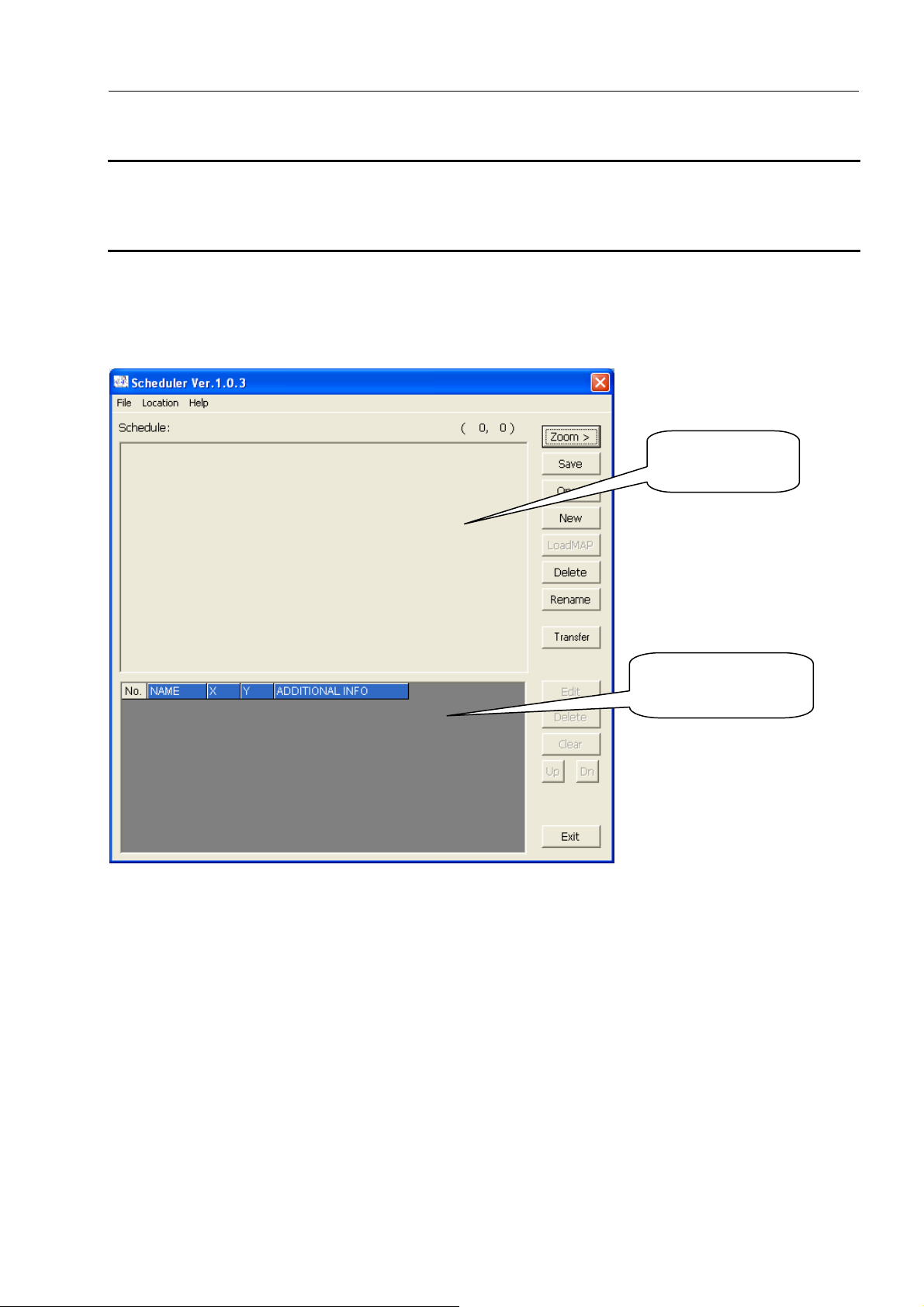
4.1. Main Screen
Map image will
be displayed here.
Location Information
will be displayed here.
12
4.2. Menu List
File Menu
For file related operations.
[New] Creates a new SCHEDULE file.
[Open] Loads a saved SCHEDULE file.
[Save] Saves a created SCHEDULE file.
[Load Map] Loads a MAP image file.
[Delete] Deletes a created SCHEDULE file.
[Rename] Renames a created SCHEDULE file.
[Exit] Closes the software.
Page 14

4. Scheduler Software
Location Menu
[Edit Location] Edits the selected Location.
[Delete Location] Deletes the selected Location.
[Clear List] Deletes all Locations.
[Up] Shifts the selected Location up one spot in the list.
[Down] Shifts the selected Location down one spot in the list.
Help Menu
[About] Shows the software version information.
4.3. Command Buttons
Zoom
Magnifies the displayed MAP.
Save
Saves the SCHEDULE that you are editing.
Open
Opens the saved SCHEDULE file.
New
Creates a new SCHEDULE file.
LoadMAP
Loads a MAP file.
The map file should be created using an image editing application beforehand.
The image must be in bitmap (.bmp) format.
Delete
Deletes a saved SCHEDULE file.
You cannot delete a file while you are editing it.
Rename
Changes the name of a saved SCHEDULE file.
You cannot change the name of a file while you are editing it.
Transfer
Transfers the saved SCHEDULE file to the instrument. When [File Transfer Software] starts,
follow procedures described in 5.File Transfer Software
Edit
Edits the selected Location.
Delete
Deletes the selected Location.
Clear
Deletes all the Locations.
Up
Shifts the selected Location up one spot in the list.
Dn
Shifts the selected Location down one spot in the list.
Exit
Closes the software.
to upload the file.
13
Page 15
4. Scheduler Software
4.4. Schedule File Creation
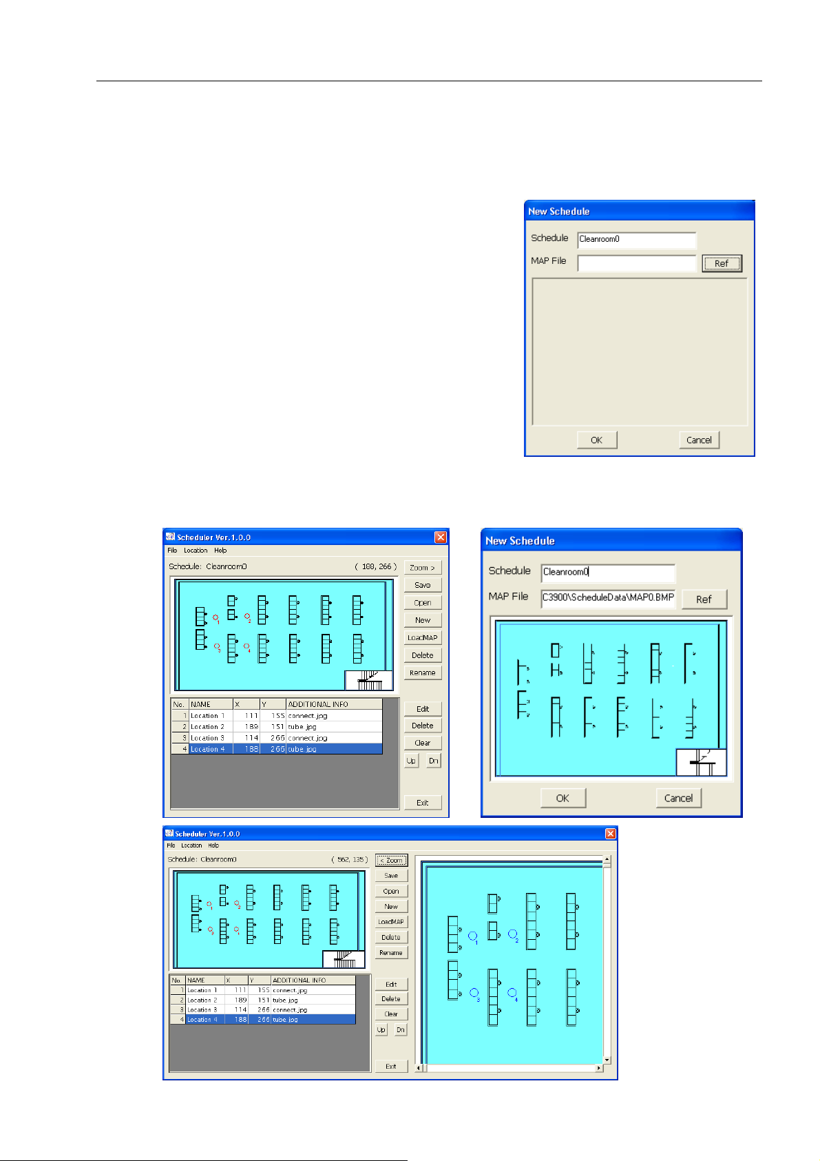
4.4.1. Creating a new file
(1) Click [File] -> [New], or
Click [New].
(2) The “New Schedule” window will be displayed.
Enter a Schedule name and specify a MAP File to load. To
select a MAP File click [Ref] to display the “Select MAP
File” window and click the file that you wish to use.
Without a MAP fi le, you cannot create a Schedule with thi s
application.
* Creating a MAP File: You may use any standard paint
program (such as MS Paint) to create a visual
representation of the measurement area(s) where you will
be using the instrument. The Scheduler Software can use
any standard bitmap (.bmp) file up to a maximum size of
1600 × 1200 pixels.
Click [OK] to return to the main screen and input the test
locations. Click [Cancel] to return to the main screen.
14
Page 16
4. Scheduler Software
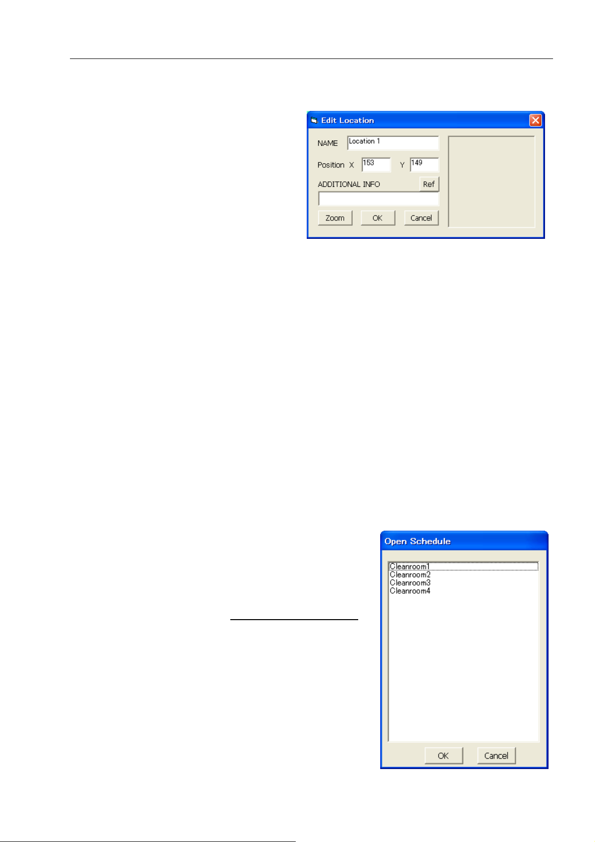
(3) To create a new measurement point click th e place on the MAP where you wish to add a location.
Then the “Edit Location” window will
open.
NAME:
Enter a Location Name.
Position:
The coordinates that you clicked are
displayed. You can edit these.
ADDITIONAL INFO:
Click on [Ref] to select an image file
for ADDITIONAL INFORMATION.
The image format should be *.jpg or *.bmp.
[Zoom] button:
Magnifies the image that was loaded in ADDITIONAL INFO.
After you complete editing, click on [OK] or [Cancel].
Click [OK] to save the edited settings.
Click [Cancel] to discard the edited settings.
Repeat this procedure to add a Location.
You can set up to 100 Locations.
(4) To edit an existing Location, select the Locatio n that you want to edit from the Location Information
list, and click [Edit]. The “Edit Location” window will be displayed and you can edit the Location
settings.
(5) To delete an existing Location, select the Location that you want to delete from the Location
Information list, and click [Delete].
(6) To delete all Locations, click [Clear].
(7) When you finish editing the Schedule, click [Save].
15
4.4.2. Editing an existing file
(1) Click [File] -> [Open], or click [Open].
(2) The “Open Schedule” window will open. Select the
Schedule file that you want to edit and click [OK].
(3) Refer to steps (3) - (7) in 4.4.1
more information on editing a file.
Creating a new file for
Page 17

play
5. File Transfer Software
16
5. File Transfer Software
Use the File Transfer Software to download stored measurement data from or upload a schedule file to the
Airborne Particle Counter.
5.1. Main Screen
Both the PC running the software and the Airborne Particle Counter must be connected to the LAN
and properly configured in order to access the Airborne Particle Counter remotely via PC.
Configure
connection settings
Files will be
dis
ed here.
5.2. Menu List
File Menu
[Exit] Closes the software.
Help Menu
[About] Shows the software version information.
Page 18

5. File Transfer Software
5.3. Destination Settings and Command Button
Host Name
Enter the Host Name of the instrument you wish to connect with. The instrument’s Host Name is
configured in the instrument’s COMMUNICATION SETTING.
You can also choose a Host Name by using [Search] which will display all the instruments currently
connected to the LAN (Refer to 3.5 Search Function
Connect
Click [Connect] to connect to the instrument config ured in Host Name.
The “Authentication” window will be displayed, prompting you to enter your User ID and Password.
Enter your User ID and Password that you use to log into the instrument and click [OK]. If the
authentication succeeds, the connection will be established.
NOTE: In order to access the instrument remotely the user must have [Administrator] or [Remote Control]
rights. Also, the instrument cannot be accessed remotely via PC if it is remote mode.
If the connection fails, a message will be displayed saying “The connection was ended because of a network
error.”
To reconnect to the instrument, click [Connect].
If the connection succeeds, the instrument screen will be displayed, and the [Connect] button will be
replaced by the [Disconnect] button.
Search
Starts a search for connected instruments (Refer to 3.5 Search Function
Measure Mode
Filters the file type that is displayed for downloading.
The files that you can select are;
Single: Single Measurement Data
Continue: Continuous Measurement Data
Inter: Interval Measurement Data
Statistic: Stats Measurement Data
ISO: ISO Mode Measurement Data
FS 209E: FS 209E Mode Measurement Data
BS 5295: BS 5295 Mode Measurement Data
EU GMP: EU GMP Mode Measurement Data
GB/T: GB/T Mode Measurement Data
ALL: All Measurement Data
).
).
17
Page 19

5. File Transfer Software
Download/Upload (Radio Button)
Toggles Upload or Download mode.
Download
Downloads the selected data file.
Upload
Uploads the selected Schedule file to the instrument.
EXIT
Closes the software.
18
Page 20

5. File Transfer Software
5.4. Downloading Measurement Data
(1) Enter “Host Name” and click [Connect] to
connect the computer with the instrument
(Refer to 5.3 Destination Settings and
Command Button).
(2) Select the [Download] radio button.
(3) Select the file that you want to download.
The selected file name will be displayed
under “File Name”.
(4) Click [Download].
(5) The “Save As” dialogue box will be
displayed. Enter a file name and click
[Save]. The file is then downloaded
from the instrument and saved to
your PC.
19
Page 21

5. File Transfer Software
5.5. Uploading a Schedule File
(1) Enter “Host Name” and click [Connect] to connect
the computer with the instrument (Refer to 5.3
Destination Settings and Command Button).
(2) Select the [Upload] radio button.
(3) Select the Schedule file that you want to upload. The
selected file name will be displayed under “File
Name”.
(4) Click [Upload]. The schedule file is then uploaded to
the instrument and the main screen will be displayed.
If the schedule name already exists in the
instrument, a message window will be
displayed asking if you want to overwrite the
file or not. Click [Yes] to overwrite the file
stored on the instrument with the file from the
PC.
If you click [No], a message window will be
displayed asking you if you want to delete the
schedule file from the instrument.
Click [Yes] to delete the Schedule file saved on
the instrument.
Click [No] to go back to the main screen.
20
Page 22

5. File Transfer Software
5.6 Search Function
Refer to 3.5 Search Function.
21
Page 23

6. Measuring Software
22
6. Measuring Software
Use the Measuring Software to collect particle, air velocity, temperature, humidity and differential pressure data
from the Airborne Particle Counter.
Start-up Operation
6.1. Operation Overview
* NOTE: The instrument must be placed in
“REMOTE MODE” when running this
program (Please refer to the instrument
manual for further directions).
(1) From the start menu, click :[(All) Programs]
-> [KANOMAX] - > [Measuring Software].
(2) The Initial Screen appears displaying the last
file that was displayed when the program was
last used.
(3) To configure LAN Settings,
go to: [Setting] -> [R LAN Setting…]
and configure the Host Name.
(Refer to 6.4.1.LAN Settings
(4) To start measuring, click [Measurement] from
the menu bar or click
(5) As shown on the right, go to [Fi le] -> [Save] to save
the data from the current measurement.
(6) To end the prog ram, go to [File] -> [Exit].
.)
Page 24

6. Measuring Software
23
6.2. Screen Structure
Menu bar and tool bar are displayed on the parent window. The menu bar and tool bar change depending on the
active window.
Tool Bar
Status Bar
Particle Graph
Window
THVP Graph
Window
Data Table Window
Program Status:
Sampling or Wait
Sampling Time
Interval
1) Toolbar
The menu items most commonly used are shown as icons on the toolbar. Click on the corresponding button to
execute the item easily.
2) Status Bar
The program status, as well as measurement status and parameters are displayed on the status bar.
No. of
Sampling
Page 25

6. Measuring Software
6.3. Data File
6.3.1. File Menu
New
Start a new file using the current configured parameters (The default file name is “NEWFILE.KRM”). (If
there is unsaved data, a dialog box appears asking if you want to save the data.)
Open…
Loads an existing file (If there is unsaved data, a dialog box appears asking if you want to save the data).
Save
Saves the current data under a file name you specify.
Print
Prints the graph or data in the active window.
Recently used documents list
Opens a recently used file.
Exit
Closes the program (If there is unsaved data, a dialog box appears asking if you want to save the data).
24
6.3.2. Data File List
The following table shows the file formats that the Measuring Software can save data as:
Measurement Data File
Data File
Excel Compatible,
CSV format or text
format
• File Name
• Format
• Contents
• File Name
• Format
• Contents
: ###.KRM
: Binary
: File information, measurement parameter, remote measurement data
: ###.CSV or ###.TXT
: Microsoft Excel compatible comma-delimited file
: measurement parameter, measurement data
Page 26

6. Measuring Software
6.4. Settings
6.4.1. LAN Settings
Click [Setting] -> [R LAN Setting…] to display the “LAN
Setting” dialog box.
Enter the Host Name of the instrument you wish to connect
with and click [OK].
You can also set the Host Name using [Search] (Refer to 3.5
Search Function).
6.4.2. Measurement Parameter Settings
Click [Setting] -> [Measurement Parameter Setting…] to
display “Measurement Parameter Setting” dialog box.
Configure the remote measurement parameter settings in the “Measurement
Parameter Setting” dialog box shown on the right. Refer to the settings table
below.
Setting Item Setting Contents
Sampling Time
Set sampling time in seconds.
Key input: Integer 6~3600
Select: 6, 8, 10, 30, 60, 300, 600, 1200
Interval Time Set interval time in minutes.
Key input: Integer 1~1440
Select: 1, 5, 10, 20, 30, 60, 120, 180
The Number of Samples Key input: Integer 1~30000
Select: 1, 10, 60, 120, 300, 600, 1200, 3000
The Unit of Particle Set the unit of particle to be used; p, p/cf or m
3
<Measurement Parameter Setting>
The Unit of Temperature Set the unit of temperature to be used;
deg C or deg F
The Unit of Velocity Set the unit of air velocity to be used;
m/s or FPM
(Please refer to your instrument manual for further information on measurement settings.)
<Measurement Parameter Explanatory Drawing>
Wait Time
Start
Measurement
Sampling Time
Interval
Sampling Time
Interval
Sampling Time
Finish
Measurement
25
The 1st Measurement The 2nd Measurement
The 20
th
Measurement
Page 27

6. Measuring Software
26
6.5. Remote Measurement
NOTE: The instrument must be placed in “REMOTE MODE” when running this program. (Please refer to the
instrument manual for further directions.)
Both the PC running the software and the Airborne Particle Counter must be connected to the LAN and
properly configured in order to access the Airborne Particle Counter remotely via PC.
6.5.1. Start/End Measurement
1) To Start a Measurement
Click [Measurement] -> [Measurement] or the
icon to start a measurement.
If the LAN is not connected properly or the HOST cannot be found after one
minute, the error message shown on the right will be displayed.
If a LAN connection error occurs, confirm the settings on the
Airborne Particle Counter and the software settings (Refer to
6.4.1. LAN settings
2) To End a Measurement
Click [Measurement] -> [Measurement Stop] or the
icon. A dialog box appears asking “Are you sure
you want to stop measurement?” Click [Yes] to stop
measurement. Data collected up to the point the
measurement was stopped will be stored.
3) To Cancel Remote Mode
Click [Measurement] -> [Remote Mode Cancel] to
cancel the remote mode on the instrument.
NOTE: If you cancel the remote mode on the instrument,
you will need to place the instrument back in remote
mode before you can begin another measurement (Please
refer to the instrument manual for further directions).
).
Page 28

6. Measuring Software
6.5.2. Measurement
Measurement Control:
During a measurement, the program performs measurement timing control, turns the Airborne Particle
Counter pump on and off, and downloads data.
Data Display:
During a measurement, you can display the time series graph and data table in real time.
(Refer to 6.6 Remote Measurement Data Display
.)
6.5.3. Measurement Data Storage
Specify the destination to save data manually after measuring.
After completing a measurement, you can spec ify a file name and destinat ion for the saved data. Data can be
saved as “.CSV (Microsoft Excel comma-delimited character file)” or “.TXT”.
For example, if you enter “Test” as a data file name and choose to save it as “.CSV”, the data is saved as
“Test.KRM” and “Test.CSV”. Also, if you choose to save it as “.TXT”, the data is saved as “Test.KRM” and
“Test.TXT”.
<If an in-progress measurement is interrupted>
If the PC is shut down unintentionally or the power goes out, data can be recovered.
Data for incomplete measurements is saved as a “temp.KRM” file in the folder where the software is stored
(Default location is: “C\:Program Files\KANOMAX\APC3900”).
You can open this file with “Measuring Software” and save it under a different name.
27
Page 29

6. Measuring Software
6.6. Remote Measurement Data Display
6.6.1. Data Display Format
The following table shows the display formats used by the Particle & THVP Graphs:
Unit Display Format Example
Particle p, p/cf, p/m3
<10000 : XXXX
≧10000 : X. XXXE + X
1.256E + 5
2568
Temperature deg C, deg F XXX. X 26.5
Humidity % XXX. X 75.3
Air Velocity m/s, FPM X. XXX 0.652
6.6.2. Particle Graph
To display the particle graph, go to [View] -> [Time Series Graph] -> [Particle] or click on the tool bar.
1) Particle Graph Window
Graphs are available with two types of vertical axis; linear and logarithm.
In the above windows, you can scroll the graph using the scroll bars. If you move the cursor over the graph it
will change to a red bar. As you position the bar over a particular time (shown on the X axis), the particle count
shown at the bottom of the graph will update to reflect the measurement data under the bar’s current location
While a measurement is in progress, the graph cursor functionality and the scroll bars are disabled.
Particle Graph (Linear) Particle Graph (Logarithm)
Data for each particle size will be
displayed in the order of
0.3µm, 0.5µm, 1µm, 3µm, 5µm and 10µm
28
Page 30

6. Measuring Software
2) Particle Graph Parameter Settings
To edit the Particle Graph Parameter Settings, click [View]
-> [Graph Parameter Edit] -> [Particle], or click on the
tool bar to display the “Particle Graph Parameter Edit”
dialog box shown on the right. Then configure the Particle
Graph Parameter Settings.
The following table lists the settings you may choose for the Particle Graph Parameters:
Setting Item Settings
Horizontal axis (time axis) range
setting
Displayed items on Vertical axis Up to 6 different particle size (0.3, 0.5, 1, 3, 5, 10 µm) can be displayed
Types of vertical axis Select Linear or Logarithm
Vertical axis display range Select a range from below;
Select a range from below:
10min, 20min, 30min, 40min, 50min, 60min
1~24 hours – on an hourly basis
1~30 days – on daily basis
on the same graph.
Linear:
10, 20, 50, 100, 200, 500, 1000, 2000, 5000,
1.00E+04, 1.00E+05, 1.00E+06, 1.00E+07, 1.00E+08, 1.00E+09
Logarithm:
10, 100, 1000,
1.00E+04, 1.00E+05, 1.00E+06, 1.00E+07, 1.00E+08, 1.00E+09
29
Page 31

play
6. Measuring Software
30
6.6.3. Temperature, Humidity, Air Velocity and Differential Pressure Graph
To display the TVHP graph, go to [View] -> [Time Series Graph] -> [Particle] or click on the tool bar.
1) THVP Graph Window
Only a linear type is available for the vertical axis for a THVP graph.
In the above window, you can scroll the graph using the scroll bars. If you move the
cursor over the graph it will change to a red bar. As you position the bar over a
particular time (shown on the X axis), the THVP count shown at the bottom of the graph
will update to reflect the measurement data under the bar’s current location.
2) THVP Graph Parameter Setting
To edit the THVP graph parameter settings, click [View] -> [Graph Parameter Edit]
-> [THVP…] to display the right dialog box, or click on the tool bar.
The following table shows the settings you may choose for the TVHP Graph Parameters:
Setting Item Settings
Horizontal axis (time axis) range setting Select a range from below:
10min, 20min, 30min, 40min, 50min, 60min
1~24 hours – on an hourly basis
1~30 days – on daily basis
Vertical axis
display range
(deg C)
Max Select: 5, 10, 15, 20, 25, 30, 35, 40, 45, 50 Te mperature
Min Select: 0, 5, 10, 15, 20, 25, 30, 35, 40, 45
Max Select: 40, 50, 60, 70, 80, 90, 100, 110, 120, 130 Te mperature
(deg F)
Min Select: 30, 40, 50, 60, 70, 80, 90, 100, 110, 120
Max Select: 10, 20, 30, 40, 50, 60, 70, 80, 90, 100 Humidity
(%)
Min Select: 0, 10, 20, 30, 40, 50, 60, 70, 80, 90
Max Select: 0.1, 0.2, 0.3, 0.4, 0.5, 0.6, 0.7, 0.8, 0.9, 1.0 Air Velocity
(m/s)
Min Select: 0.0, 0.1, 0.2, 0.3, 0.4, 0.5, 0.6, 0.7, 0.8, 0.9
Max Select: 0.1, 0.2, 0.3, 0.4, 0.5, 0.6, 0.7, 0.8, 0.9, 1.0 Air Velocity
(FPM)
Differential
Pressure (Pa)
Min Select: 0.0, 0.1, 0.2, 0.3, 0.4, 0.5, 0.6, 0.7, 0.8, 0.9
Max Select: 200, 150, 100, 50, 0, -50, -100, -150, -200
Min Select: 200, 150, 100, 50, 0, -50, -100, -150, -200
*Refer to 6.4.2 Measurement Parameter Settings if you want to change the unit of temperature or air velocity
used for measuring.
T : Temperature
H : Humidity
V : Air V elocity
P : Differential Pressure
Te mperature, Humidity, Air Velocity,
and Differential Pressure data will be
dis
ed from the left.
Page 32

6. Measuring Software
6.6.4.Data Table
Data values are listed in chronological order in the data table window. The window is resizable.
Fig. Data Tab le Window
To display the measuring data table, go to [View] -> [Data Table Display] or click on the tool bar.
31
Page 33

6. Measuring Software
32
6.7. Other Functions
6.7.1. Switching Languages
You can switch the language between English and Japanese by clicking [Option] on the menu bar.
6.7.2. Windows Arrange
Click [Windows] -> [Windows Arrange] to display the graph windows and data table window.
If [Standard Arrange] is checked, the graph and data table window will automatically resize when you change the
main window size.
If [Window Arrange] is checked the graph and data table windows will not automatically resize if the main
window size is changed.
You may check or uncheck [Measuring Data Table], [THVP Graph] and [Particle Graph] to show or hide the
respective windows.
6.7.3. Software Version
Click [Help] -> [About] to check the software version information as shown below.
Page 34

6. Measuring Software
6.7.4. Printing Function
To print the current active graph or data list, click [File] -> [Print], or click on the tool bar.
33
Page 35

7. Users Management Software
7.User Management Software
Use the User Management Software to manage users, measurement data, and log data on the instrument.
7.1. When You First Start Software
Both the PC running the software and the Airborne Particle Counter must be connected to the LAN
and properly configured in order to access the Airborne Particle Counter remotely via PC.
7.1.1. Start Screen
When the software starts, the “User Authentication”
window will be displayed.
If you are starting the software for the first
time, no user is registered.
Enter [administrator] for User ID,and [1234]
for Password.
(This user ID and password will be disabled
automatically after registering a new user.)
34
7.1.2. Specifying Data Storage Folder and SD(MMC) Card Drive Name
Select [File]->[Setting] to specify the Data storage folder, and the card drive name.
[Data storage folder]
Enter the path for the location data files will be saved to (Example: C:\Program Files\KANOMAX\3900
Data Storage), or click […] to select a folder.
[Drive Name of SD(MMC) Card]
Select a SD(MMC) card drive name from the list of drives recognized by the computer.
Page 36

7. Users Management Software
7.1.3. Registering a New Local User
When starting the software for the first time, be sure to register one or more local users
with [Manage Users] right.
To register a new local user, click [User]
->[Local], then click [Register].
In the “Information” tab, enter the following:
User Name (1 to 52 alphanumeric characters),
User ID (4 to 16 alphanumeric characters),
Password (4 to 16 alphanumeric characters),
Confirm Password,
Company/Division (up to 100 characters),
and Memo (up to 100 characters).
Passwords expire every 180 days.
If a password expires, the User ID will become
invalid until a new password is set.
In the “Qualification” tab, you may specify the
following user rights:
35
Manage Users: allows a user to register a new user,
and edit or delete registered users.
Without this right, a user can only
edit their own password.
Decrypt: allows a user to decrypt stored data.
Approval1: allows a user to give their approval as
“Approval1” to a stored data file.
Approval2: allows a user to give their approval as
“Approval2” to a stored data file.
(NOTE: If an item is checked, the user will be granted
that right.)
Page 37

7. Users Management Software
After all user information and qualifications have been entered, click [OK] to register a new user or click
[Cancel] to discard the current user data. The “User Management” window then appears, displaying a list of
all currently registered users.
If you wish to register another new user, click [Register].
You do not need to register all the users the first time you use the software. A user with [Manage Users]
rights can register a new user at any time.
7.2. Starting Software After Registering Local Users
7.2.1. Starting Software
When the software starts, the “User Authentication” window will be displayed.
Enter the User ID and Password
of a registered local user
to start the software.
When an expiration date on a password draws near, the following messages will be displayed.
It is recommended that you change an expiring password as soon as possible.
When the password will expire in 6 to 10 days When the password will expire in 5 days
When the password will expire in a day When the password has already expired
Click [OK]. If the password has not expired, the ma in screen will be displayed.
36
Page 38

7. Users Management Software
If the password has expired, the “Set Password” window will be di splayed.
Enter the current password in the “Old password” box, and a new password in the “New password”
and the “Confirm new password” boxes.
Click [OK] to check the old password and save a new
password. Then, the main screen will be displayed.
Click [Cancel] to discard changes and return to the “User
Authentication” window.
When a registered user starts the software,
the files in the [Data storage folder] are
displayed as shown on the right.
The [Decrypt], [Approval1], and
[Approval2] buttons are automatically
enabled or disabled, depending on the
user’s rights.
37
Page 39

7. Users Management Software
7.2.2. Download Button
The [Download] button transfers measurement data or log files from the instrument to the computer.
The transferred data will be saved in the folder specified in [Data storage folder] (Refer to 7.1.2 Specifying
Data Storage Folder and CF Card Drive Name).
Click [Download] to
display the “File Transfer” window.
Enter the Host Name of the instru ment
you wish to connect to, and click the
[Connect].
If you can not connect to the instru ment
by entering the Host Name, click
[Search] to check if the instrument is
connected to the LAN.
(Refer to 3.5 Search Function
.)
38
Enter the User ID and Password as
registered in the instrument.
The User ID must have administrative
rights or [Copy Files] rights
in the instrument.
Click [OK] to authenticate the user.
When the connection is completed, th e
data list in the instrument will be
displayed.
Page 40

7. Users Management Software
Under the “File Selection”,
you can switch between
[Data File] and [Log File].
Select a file to transfer, and click [Download].
When the download is finished,
the message “The file has finished
downloading” will be displayed.
Click [OK].
To transfer another file,
repeat the above procedure.
When finished, click [Close] to
exit the “File Transfer” window.
A list of transferred files will be
displayed.
39
Page 41

7. Users Management Software
7.2.3. Decrypt Button
A user with [Decrypt] rights can decrypt measurement data.
Select a file to decrypt, and click [Decrypt].
Enter a file name and click [Save].
The data will be saved in CSV format.
40
Page 42

7. Users Management Software
7.2.4. Approval1/Approval2 Button
A user with [Approval1] or [Approval2] rights can approve measurement data.
Select a file to approve, and click [Approval1] or [Approval2].
A dialog box appears
asking if you approve.
Click [OK] or [Cancel].
If you click [OK],
your approval will be registered
to the file.
If you click [Cancel],
the main screen will be displayed.
7.2.5. User Management [3910 Online]
If the software is started by a user with [Manage Users] rights,
you can register, edit, and delete users registered in the instrument.
Download the user file from the instrument to register, edit, or delete users.
After registering, editing, or deleting users, upload the user file to the instrument.
Click [User]->[3910 Online]
to open the “File Transfer” window.
Enter the Host Name of the instrument you wish to
connect with, and click [Connect].
If you can not connect to the instrument by entering
the Host Name, click [Search] to check
if the instrument is connected to the LAN.
(Refer to 3.5 Search Function
.)
41
The “User Authentication” window will be
displayed. Enter a User ID and Password
for the administrator registered in the instrument.
Click [OK] to authenticate the user.
When the connection is completed, the user
list from the instrument will be displayed.
Page 43

7. Users Management Software
・Download
Select a file, and click [Download]
to start downloading.
When the download is finished,
the message “The file has finished
downloading” will be displayed.
Click [OK].
The user list is displayed and you can
register a new user or edit existing users.
42
Page 44

7. Users Management Software
・Registering a new user
Click [Register] to register a new user.
You can specify user information
and authorization settings.
In the “Information” tab, enter:
User Name (1 to 52 alphanumeric characters),
User ID (4 to 16 alphanumeric characters),
Password (4 to 16 alphanumeric characters),
Confirm Password,
Company/Division (up to 100 characters),
Memo (up to 100 characters)
(Reminder: Passwords expire every 180 days.)
If [Administrator] is checked, the user will be
granted administrative rights. In this case, all
the Authorization settings are checked
and displayed in gray as shown below.
43
If [Administrator] is unchecked, you may specify
Page 45

7. Users Management Software
the user rights individually by checking off each
box for the right(s) you wish to assign as shown to
the right.
[Description of rights in the instrument]
Access Control Panel: The user is authorized to change settings in the control panel
Change Measurement Mode: The user is authorized to switch measurement modes
Copy Files: The user is authorized to copy measurement files and log files
Delete Files: The user is authorized to delete measurement files and log files
View logs: The user is authorized to view log files
When finished assigning rights, click [OK] to save the settings or [Cancel] to discard the changes.
44
Page 46

7. Users Management Software
・Edit
To edit an existing user, select the user name and click [Edit].
The user information will be displayed.
Edit the items as necessary, and click [OK] to save the changes or [Cancel] to discard the changes.
・Delete
To delete an existing user, select the user name and click [Edit].
The user information will be displayed.
Click [Delete] and a dialog box appears asking if you want to delete the user.
Click [OK] to delete the user or [Cancel] to leave the user
as is.
45
Page 47

7. Users Management Software
・Upload
To upload user data from a PC to an instrument click the
[X] button on the user list window, to display the “File
Transfer” window. (NOTE: The file transfer screen will
only appear if you have registered a new user or edited an
existing user. Otherwise you will be returned to the main
screen when you close the user list window.)
Enter the Host Name of the instrument you wish to
connect with, and click [Connect].
If you can not connect to the instrument by entering
the Host Name, click [Search]
to check if the instrument is connected to the LAN.
(Refer to 3.5 Search Function
.)
The “User Authentication” window will
be displayed.
Enter a User ID and Password with administrative
rights or [Copy Files] rights as registered in the
instrument.
Click [OK] to authenticate the user. When the
connection is completed, the user data list
in the PC will be displayed.
Select a file,
and click [Upload]
to start uploading.
When the upload is finished,
the message “The file has finished uploading”
will be displayed.
Click [OK].
46
Page 48

7. Users Management Software
47
7.2.6. User Management [3910 SD Card]
If the software is started by a user with [Manage Users] rights, you can register, edit, and delete user information
stored on a SD(MMC) card.
Click [User]->[3910 SD Card], a dialog box appears displaying drives specified in [Drive Name of SD(MMC)
Card ].
(Refer to 7.1.2 Specifying Data Storage Folder and SD(MMC) Card Drive Name
Select a user list file, and click [Open]. (By default this file is Users.dat located in the PARAM folder.)
When the file is open, the user list will be displayed.
You can register and edit users here just as
you would in [User]->[3910 Online].
(Refer to 7.2.5. User Management [3910
Online] for instructions on registering, editing
and deleting users.)
.)
Page 49

7. Users Management Software
48
7.2.7. User Management [Local]
If the software is started by the user with [Manage Users] right, you can register, edit, and delete users registered
in the PC.
The user without [Manage Users] right can only ch ange the password for logged-in users.
[When the user with [Manage Users] right logs in]
If you click [User]->[Local], the list of registered users will be displayed.
・Registering a new user
Please refer to 7.1.3 Registering a New Local User
.
Page 50

7. Users Management Software
・Edit
To edit an existing user, select the user name and click [Edit].
The user information will be displayed.
Edit the items as necessary, and click [OK] to save the changes or [Cancel] to discard the changes.
・Delete
To delete an existing user, select the user name and click [Edit].
The user information will be displayed.
Click [Delete] and a dialog box appear asking if you want to delete the user.
Click [OK] to delete the user or [Cancel] to leave the user as is.
・Exit
49
Page 51

7. Users Management Software
Click the [X] button to close the user list window, and the main screen will be displayed.
[When the user without [Manage Users] right logs in]
If you click [User]->[Local], the edit window of logged-in users will be displayed.
・Edit
You can only change passwords.
Change a password when the password
will expire soon.
Click [OK] to save the changes or
[Cancel] to discard the changes.
・Exit
Click [OK] or [Cancel], and the main screen will be displayed.
50
Page 52

8. Miscellaneous Notes
8. Miscellaneous Notes
If you forgot the password(s) for all local users with [Manage Users] rights, please contact us for assistance.
51
Page 53

USA & Europe
KANOMAX USA, INC.
PO Box 372, 219 Route 206, Andover, NJ 07821 U.S.A.
TEL: 1-800-247-8887 / 1-973-786-6386 FAX: 1-973-786-7586
URL: http://www.kanomax-usa.com/
E-Mail: info@kanomax-usa.com
Japan & Asia
KANOMAX JAPAN, INC.
2-1 Shimizu Suita City, Osaka 565-0805, Japan
TEL: 81-6-6877-0183 FAX: 81-6-6877-5570
URL: http://www.kanomax.co.jp/
E-Mail: sales@kanomax.co.jp
China
Shenyang Kano Scientific Instrument Co., Ltd
No. 12, 4 Jia Wencui Road Heping District
Shenyang City, PRC
TEL: 86-24-23845309 FAX: 86-24-23898417
URL: http://www.kanomax.com.cn/
E-Mail: sales@kanomax.com.cn
 Loading...