

Page 1
AIRBORNE PARTICLE COUNTER SOFTWARE
Operation Manual
Please keep this operation manual handy for future reference.
01000
08.09
Page 2

* The operation manual is stored in Adobe PDF format, which can be read by Adobe Acrobat 4.x or higher.
* Windows 9x/NT/2000/XP/Vista is a registered trademark of Microsoft Corporation.
* The unauthorized use or duplication, either whole or in part, of this Software or its Operation Manual is
strictly forbidden.
* The contents of this Operation Manual are subject to change for quality improvement without notice.
Page 3

Table of Contents
1. Overview.............................................................................................................. 1
1.1. Packing List............................................................................................................................1
1.2. System Overview ...................................................................................................................1
2. Installation .......................................................................................................... 2
2.1. Installation..............................................................................................................................2
2.2. Starting and Closing a Program..............................................................................................2
2.3. Uninstallation .........................................................................................................................2
3. Remote Console Software..................................................................................3
3.1. Main Screen............................................................................................................................3
3.2. Menu List ...............................................................................................................................4
3.3. Destination Settings and Command Buttons..........................................................................4
3.4. How to Operate remote Console Software.............................................................................5
3.5. Search Software......................................................................................................................6
4. Scheduler Software.............................................................................................7
4.1. Main Screen............................................................................................................................7
4.2. Menu List ...............................................................................................................................7
4.3. Command Button ...................................................................................................................8
4.4. Schedule File Creation ...........................................................................................................9
4.4.1. Creating a new file .............................................................................................................................9
4.4.2. When editing an existing file............................................................................................................10
4.5. Setting a Folder for Saving File ...........................................................................................11
5. File Transfer Software......................................................................................12
5.1. Main Screen..........................................................................................................................12
5.2. Menu List .............................................................................................................................12
5.3. Destination Setting and Command Button...........................................................................13
5.4. Downloading Measurement Data.........................................................................................14
5.5. Uploading Schedule File ......................................................................................................15
5.6 Search Software....................................................................................................................16
6. Measuring Software.........................................................................................17
6.1. Operation Procedure.............................................................................................................17
6.2. Screen Structure ...................................................................................................................18
6.3. Data File ...............................................................................................................................19
6.3.1. File Menu .........................................................................................................................................19
6.3.2. Data File List....................................................................................................................................19
6.4. Setting...................................................................................................................................20
6.4.1. LAN Port Setting..............................................................................................................................20
6.4.2. Measurement Parameter Setting.......................................................................................................20
6.5. Remote Measurement...........................................................................................................21
6.5.1. Start/End Measurement ....................................................................................................................21
6.5.2. Measurement ....................................................................................................................................22
Page 4

6.5.3. Measurement Data Storage...............................................................................................................22
6.6. Remote Measurement Data Display.....................................................................................23
6.6.1. Data Display Format ........................................................................................................................23
6.6.2. Particle Graph...................................................................................................................................23
6.6.3. Temperature, Humidity, Air Velocity and Differential Pressure Graph............................................25
6.6.4. Data Table.........................................................................................................................................26
6.7. Other Functions ....................................................................................................................27
6.7.1. Switching Languages .......................................................................................................................27
6.7.2. Windows Arrange............................................................................................................................. 27
6.7.3. Software Version ..............................................................................................................................27
6.7.4. Printing Function..............................................................................................................................28
7. Troubleshooting................................................................................................29
Page 5

1. Overview
1. Overview
1.1. Packing List
The following item is included in this package.
QTY
1. AIRBORNE PARTICLE COUNTER SOFTWARE CD-ROM 1
If the CD-ROM is missing or damaged, please contact your local distributor immediately.
1.2. System Overview
1
This software package includes four programs as follows;
- Remote Console Software
- Scheduler Software
- File Transfer Software
- Measuring Software
Use the Remote Console Software to operate the Airborne Particle Counter remotely via computer.
Use the Scheduler Software to create a schedule file for use when performing a measurement.
Use the File Transfer Software to download stored measurement data from or upload a schedule file to the
Airborne Particle Counter.
Use the Measuring Software to collect particle, air velocity, humidity and differential pressure data from the
Airborne Particle Counter.
Applicable Computer Requirements:
Model: IBM PC compatible
USB Port: At least 2 available USB ports
Ethernet Connector: 1 available Ethernet port
OS English or Japanese Windows 2000 SP4 or higher, Windows XP SP1 or higher,
Windows Vista SP1 or higher
Network Requirements:
Your Firewall and/or Network Router settings may limit your Network connectivity while using this
software. If you experience connectivity issues, please configure the following settings.
- When using the Remote Console Software or the Measuring Software, open TCP port “12344” and “12346.
- When using the Search Software, open UDP port “12345”.
- When using the File Transfer Software, open FTP port “21”.
Please refer to your Firewall or Router operation manual.
If you have any questions regarding the settings or network, please contact your network administrator.
Page 6

2. Installation
2. Installation
2.1. Installation
When installing the software, be sure to log in with a user having administrative rights and follow the
procedure below.
Insert the product CD-ROM into the CD-ROM drive. The installer will start automatically and the
installation will begin. Follow the instructions displayed on the screen.
If the installer does not start automatically, follow the directions below to install the software.
* This operation can be started from the Windows Explore menu.
(1) Execute the “Setup.exe” file stored on the product CD-ROM.
(2) Follow the instructions displayed on the screen.
(3) When the installation is completed successfully, a “KANOMAX” folder will be added to the “All
Program” list of the “Start” menu.
2
2.2. Starting and Closing a Program
To Start the AIRBORNE PARTICLE COUNTER Remote Console Software:
From the start menu, click: [All Programs] -> [KANOMAX] -> [Remote Console Software].
The main window of the software will be displayed.
To Start the AIRBORNE PARTICLE COUNTER Scheduler Software:
From the start menu, click: [All Programs] -> [KANOMAX] -> [Scheduler Software].
The main window of the software will be displayed.
To Start the AIRBORNE PARTICLE COUNTER File Transfer Software:
From the start menu, click: [All Programs] -> [KANOMAX] -> [File Transfer software].
The main window of the software will be displayed.
To Start the AIRBORNE PARTICLE COUNTER Measuring Software:
From the start menu, click: [All Programs] -> [KANOMAX] -> [Measuring Software].
The main window of the software will be displayed.
To close the software:
- From the [File] menu, select [Exit], or
- Click the [x] button located at the right end of the title bar of the main window.
2.3. Uninstallation
(1) Open [My Computer] -> [Control Panel] -> [Add or Remove Programs].
(2) Select [AIRBORNE PARTICLE COUNTER Software] from the list, and click [Remove] button.
Page 7

3. Remote Console Software
3. Remote Console Software
3.1. Main Screen
You need to connect LAN cable to the Ethernet connector when using this program.
Menu Bar
Remote Screen will be
displayed here.
Connection Settings,
Connect Buttons etc.
3
Page 8

3. Remote Console Software
3.2. Menu List
File Menu
For file related operations.
[Exit] To close the software.
Help Menu
[About] To view the software version information.
3.3. Destination Settings and Command Buttons
Host Name
Enter the Host Name for the instrument you wish to connect with. The instrument’s Host Name is
configured in the instrument’s COMMUNICATION SETTING.
You can also set the Host Name using the Search command which will display all instruments currently
connected to the LAN.
When you know the IP address of the instrument you wish to connect with, you can enter the IP address.
Connect
Click “Connect” to connect to the instrument configured in Host Name.
When the computer cannot connect to the instrument successfully, a message will be displayed saying “The
connection was ended because of a network error. This application should be restarted.”
Before attempting to connect to the instrument again, shut down the software, check the cable connections
and the settings and restart the software.
When the computer is connected to the instrument successfully, the instrument’s screen will be displayed on
the computer. The [Connect] button will become [Disconnect] button.
Search
Starts a search for connected instruments.
EXIT
Closes the software.
4
Page 9

3. Remote Console Software
3.4. How to Operate Remote Console Software
After the computer is successfully connected to the instrument, the same screen shown on the instrument
will be displayed on the computer.
Click a button on the display to operate in the same manner as you operate the instrument.
Due to LAN communication lag you may notice a delay in reaction to your commands.
If the computer becomes unresponsive for a minute or longer, the computer may be disconnected or a
problem may be occurring with the LAN communication. If that is the case, close the software by
clicking [Exit]. Check the LAN communications and start the software.
NOTE: If you select [MENU] -> [REMOTE] while using the “Remote Console Software”, this will
put the instrument in remote mode and the communication link between the instrument and PC will
be terminated. The instrument should only be placed in remote mode for connectivity when using the
“Measuring Software” program.
Operation Screen
5
Page 10
3. Remote Console Software
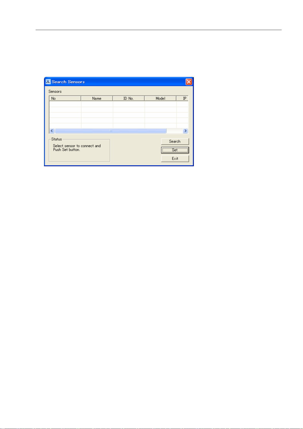
3.5.Search Software
Click [Search] to activate the Airborne Particle Counter Search Software.
Click [Search] to search for instruments connected on the LAN.
When a connected instrument is found, it will be listed in the [Search Sensors] window shown above.
Select the instrument that you want to connect with and click [Set]. The name of the instrument selected will
be displayed on the Remote Console Software or File Transfer Software.
Click [Exit] to close the software.
6
Page 11
4. Scheduler Software
4. Scheduler Software
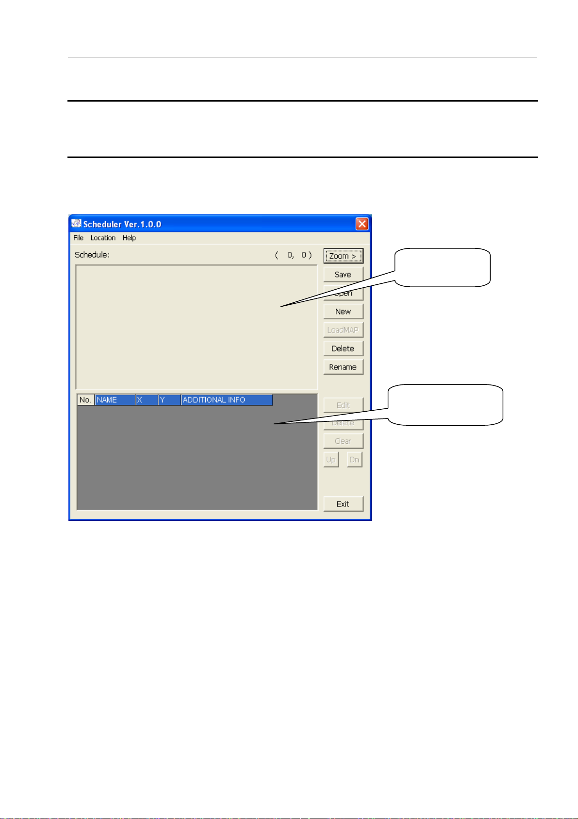
4.1. Main Screen
Map image will
be displayed here.
Location Information
will be displayed here.
7
4.2. Menu List
File Menu
For file related operations.
[New] To create a new SCHEDULE file.
[Open] To load a saved SCHEDULE file.
[Save] To save a created SCHEDULE file.
[Load Map] To load MAP image file.
[Delete] To delete a created SCHEDULE file.
[Rename] To rename a created SCHEDULE file.
[Option] To select a folder to save SCHEDULE file.
[Exit] To close the software.
Page 12

4. Scheduler Software
Location Menu
[Edit Location] To edit the selected Location.
[Delete Location] To delete the selected Location.
[Clear List] To delete all Locations.
[Up] Move the cursor up in the Location Information list.
[Down] Move the cursor down in the Location Information list.
Help Menu
[About] To show the software version information.
4.3. Command Button
[File]
Zoom >
To magnify the displayed MAP.
Save
To save the SCHEDULE that you are editing.
Open
To open the saved SCHEDULE file.
New
To create new SCHEDULE file.
LoadMAP
To load MAP file.
Map file should be created using an image editing application beforehand.
The image must be in bitmap format.
Delete
To delete the saved SCHEDULE file.
You cannot delete a file while you are editing it.
Rename
To change the name of the saved SCHEDULE file.
You cannot change the name of the file while you are editing it.
[Edit Location]
Edit
To edit the selected Location.
Delete
To delete the selected Location.
Clear
To delete all the Locations.
Up
To move the cursor up in the Location Information list.
Dn
To move the cursor down in the Location Information list.
Exit
To close the software.
8
Page 13

4. Scheduler Software
4.4. Schedule File Creation
4.4.1. Creating a new file
(1) Click [File] -> [New], or
Click [New].
(2) The “New Schedule” window will be displayed.
Enter a Schedule name and specify a MAP File to load. To
select a MAP File click [Ref] to display the “Select MAP
File” window and click the file that you wish to use.
* Creating a MAP File:
Use a graphics painting program such as MS Paint to
create a layout of the measurement area, and save it in
BMP format. Without a MAP file, you cannot create a
Schedule in this application.
The maximum usable image size is 1600 × 1200 dot.
Click [OK] to return to the main screen and input test
locations. Click [Cancel] to return to the main screen.
9
Page 14

4. Scheduler Software
(3) Click on a measurement point on the displayed MAP.
Then “Edit Location” window will open.
NAME:
Enter Location Name.
Position:
The coordinates that you clicked are
displayed. You can edit these.
ADDITIONAL INFO:
Click on [Ref] button to select an
image file for ADDITIONAL
INFORMATION.
The image format should be *.jpg or *.bmp.
[Zoom] button:
To magnify the image that was loaded in ADDITIONAL INFO.
After you complete editing, click on [OK] or [Cancel].
Click [OK] to save the edited settings.
Click [Cancel] to discard the edited settings.
Repeat this procedure to add a Location.
You can set up to 100 Locations.
(4) To edit the configured Location, select the Location that you want to edit from the Location
Information list, and click [Edit]. “Edit Location” window will be displayed and you can edit the
Location.
(5) To delete the selected Location, select the Location that you want to delete from the Location
Information list, and click [Delete].
(6) To delete all Locations, click [Clear].
(7) When you finish editing Schedule, click [Save].
The edited Schedule will be saved in the folder configured by [File] -> [Option].
10
4.4.2. When editing an existing file
(1) Click [File] -> [Open], or
Click [Open] button.
(2) “Open Schedule” window will open. Select a Schedule file
that you want to edit and click [OK].
(3) Edit the file referring to (3), (4), (5), (6) and (7) in
4.4.1
Creating a new file.
Page 15

4. Scheduler Software
4.5. Setting a Folder for Saving File
To set a folder, go to [File] -> [Option].
“Browse for Folder” window will open. The currently selected folder is indicated in blue.
To change the folder for saving data, select the folder and set it.
[NOTE]:
Do not perform this operation while creating Schedule data as the data you are working on may
be discarded. When creating shedule data, save the data first before setting a folder for saving the
file.
11
Page 16

play
5. File Transfer Software
5. File Transfer Software
5.1. Main Screen
You need to connect LAN cable to the Ethernet connector when using this program.
Configure
connection setting
File will be
dis
ed here.
12
5.2. Menu List
File Menu
For file related operations.
[Exit] To close the software.
Help Menu
[About] To show the software version information.
Page 17

5. File Transfer Software
5.3. Destination Setting and Command Button
Host Name
Enter the Host Name of the instrument you wish to connect with. The instrument’s Host Name is
configured in the instrument’s COMMUNICATION SETTING.
You can also set the HOST NAME using the Search command which will display all instruments currently
connected to the LAN.
When you know the IP address of the instrument you wish to connect with, you can enter the IP address.
Connect
To connect to the instrument configured in Host Name.
When the computer is connected with the instrument successfully, the Download or Upload button will be
activated.
After the computer is connected with the instrument, “Connect” button will become “Disconnect” button.
Search
Starts a search for connected instruments.
Measure Mode
Select the file type that is displayed when downloading.
The files that you can select are;
Single: Single Measurement Data
Sequential: Sequential Measurement Data
Inter: Interval Measurement Data
Statistic: Stat Measurement Data
ISO: ISO Mode Measurement Data
FS 209E: FS 209E Mode Measurement Data
BS 5295: BS 5295 Mode Measurement Data
EC GMP: EC GMP Mode Measurement Data
GB/T: GB/T Mode Measurement Data
ALL: All Measurement Data
Download/Upload (Radio Button)
Select Download or Upload.
Select Download and connect the computer to the instrument. Then measurement data stored on the
instrument will be displayed.
Click [Upload] to display the SCHEDULE file saved in 4. Scheduler Software
Download
To download the selected data file.
Upload
To upload the selected Schedule file to the instrument.
EXIT
To close the software.
13
Page 18

5. File Transfer Software
5.4. Downloading Measurement Data
(1) Enter “Host Name” and click [Connect] to
connect the computer with the instrument.
(2) Choose the radio button [Download].
(3) Select the file that you want to download. The
selected file name will be displayed in the
“File Name”.
(4) Click [Download].
(5) “Save As” dialogue box will be
displayed. Enter the file name and
click [Save].
(6) After the file is downloaded from
the instrument, it will be saved.
14
Page 19

5. File Transfer Software
5.5. Uploading Schedule File
(1) Enter “Host Name” and click [Connect] to connect
the computer with the instrument.
(2) Choose the radio button [Upload].
(3) Select the Schedule file that you want to upload. The
selected file name will be displayed in the “File
Name”.
(4) Click [Upload].
(5) After the data is uploaded to the instrument, the data
will be saved and the main screen will be displayed.
If the same Schedule name already exists, a
message window will be displayed asking if
you want to overwrite the file or not.
Click [Yes] to overwrite the file and upload it.
If you click [No], a message window will be
displayed asking you if you want to delete the
same name of the Schedule file which is already
saved.
Click [Yes] to delete the Schedule file saved on
the instrument.
Click [No] to go back to the main screen.
15
Page 20

5. File Transfer Software
5.6 Search Software
Refer to 3.5 Search Software.
16
Page 21

6. Measuring Software
6. Measuring Software
17
6.1. Operation Procedure
* NOTE: The instrument must be placed in
“REMOTE MODE” for connectivity when
running this program.
(1) Start the program.
(2) Initial Screen
The last file used before closing the program
will be displayed.
(3) LAN Setting
Go to: [Setting] -> [R LAN Setting…]
to configure the LAN Port and HOST
Name.
(4) Start Measuring
(5) As shown on the right, go to [File] -> [Save] to save
data.
(6) To end the program, go to [File] -> [Exit].
Start-up Operation
(Executable File: AirborneParticleCounter.EXE)
Remote Measurement
Click [Measurement] from the menu bar or click
the icon
to start a measurement.
Page 22

6. Measuring Software
18
6.2. Screen Structure
Menu bar and tool bar are displayed on the parent window. The menu bar and tool bar change depending on the
active child window.
Particle Graph
Status Bar
Program Status:
Sampling or Wait
1) Toolbar
The menu items most commonly used are shown as icons on the toolbar. Click on the corresponding button to
execute the item easily.
2) Status Bar
The program status, data status and measurement parameters are displayed on the status bar.
Tool Bar
Window
Data Table Window
Sampling Time
Interval
THVP Graph
Window
No. of
Sampling
Page 23

6. Measuring Software
6.3. Data File
6.3.1. File Menu
1) New Document
Click [New] to execute the following:
(1) If there is unsaved data in the memory, a dialogue box appears asking if you want to save the data.
Choose whether to save the data or not.
(2) A new file will be displayed with the file name of “NEWFILE.KRM”. The previous data will be cleared
but the configured parameters are kept.
2) Open
Click [Open] to execute the following:
(1) If there is unsaved data in the memory, a dialog box appears asking if you want to save the data.
Choose whether to save the data or not.
(2) “Open” dialog box shows up to open an existing file.
3) Save
Click [Save] to display “Save as …” dialog box and you can save the data with a specified file name.
4) Print
Click [Print] to print out the graph or data list on the active child window.
5) Recently used documents
Open the files recently used.
6) Exit
Click [Exit] to perform the following:
(1) If there is unsaved data in the memory, a dialog box appears asking if you want to save the data.
Choose whether to save the data or not.
(2) Exit the program.
19
6.3.2. Data File List
Measurement Data File
• File Name
• Format
• Contents
Data File
Excel Compatible,
CSV format or text
format
• File Name
• Format
• Contents
: ###.KRM
: Binary
: File information, measurement parameter, remote measurement data
: ###.CSV or ###.TXT
: Microsoft Excel comma-delimited file
: Remote Measurement: measurement parameter, measurement data
Dump : dump data
Page 24

6. Measuring Software
6.4. Setting
6.4.1. LAN Port Setting
Click [Setting] -> [R LAN Setting…] to display
“LAN Setting” dialog box.
Specify port (ID configured in the REMOTE MODE setting on the
main instrument to be connected) and HOST name (Host Name
configured in Communication setting on the main instrument to be
connected) in the combo box.
6.4.2. Measurement Parameter Setting
Click [Setting] -> [Measurement Parameter Setting…] to
display “Measurement Parameter Setting” dialog box.
Configure the remote measurement parameter settings in
the “Measurement Parameter Setting” dialog box shown
on the right. Refer to the setting table below.
Setting Item Setting Contents
Sampling Time
Set sampling time in seconds.
Key input: Integer 6~3600
Select: 6, 8, 10, 30, 60, 300, 600, 1200
Interval Time Set interval time in minutes.
Key input: Integer 1~1440
No. of Samples
Select: 1, 5, 10, 20, 30, 60, 120, 180
Key input: Integer 1~30000
Select: 1, 10, 60, 120, 300, 600, 1200, 3000
<Measurement Parameter Explanatory Drawing>
Wait Time
Start
Measurement
Sampling Time
Interval
Sampling Time
Interval
Sampling Time
Finish
Measurement
20
The 1st Measurement The 2nd Measurement
The 20
th
Measurement
Page 25

6. Measuring Software
6.5. Remote Measurement
To perform remote measurement, select REMOTE MODE on the Airborne Particle Counter by selecting:
[MENU] -> [REMOTE].
You need to connect LAN cable to the Ethernet connector when using this program.
6.5.1. Start/End Measurement
1) Start Measurement
Click [Measurement] -> [Measurement] or
button to display “Measurement Parameter
Setting” dialog box. Configure the settings and
click [Measure] to start a measurement.
When LAN is not connected properly or HOST cannot be found for one
minute, the error message shown on the right will be displayed.
When a LAN connection error occurs, confirm the setting on the
Airborne Particle Counter and the software setting as shown on
the right. Also, check if the network environment is established.
2) End Measurement
Click [Measurement] -> [Measurement Stop] or
button. A dialog box appears asking “Are you sure
you want to stop measurement?” Click [Yes] to stop
measurement. Data collected until the measurement
was stopped will be stored. The number of data will
be the actual number of the data collected.
21
Page 26

6. Measuring Software
6.5.2. Measurement
1) Measurement Control
During a measurement, this program performs measurement timing control, turns ON/OFF the pump of the
Airborne Particle Counter, and downloads data.
2) Data Display
During a measurement, you can display the time series graph and data table in real time.
For details, refer to 6.2 Screen Structure
.
6.5.3. Measurement Data Storage
Specify the destination to save data manually after measuring.
Before starting a measurement, specify the file name and the destination to save. Data is saved as “.CSV
(Microsoft Excel comma-delimited character file)”.
For example, if you enter “Test” as a data file name and choose to save it as “.TXT”, the data is saved as
“Test.KRM” and Test.CSV”.
<When the PC in use for measurement is forcibly terminated>
Even if the PC is shut down unintentionally, the data can be recovered.
Data for uncompleted measurements are saved as “temp.KRM” file in the folder where the software is stored
(Normally “C:Program Files¥KANOMAX¥APC3900”).
Open this file in the “Airborne Particle Counter Measuring Software” and save it as an arbitrary name.
22
Page 27

6. Measuring Software
6.6. Remote Measurement Data Display
6.6.1. Data Display Format
Unit Display Format Example
Particle CNT <10000 : XXXX
≧10000 : X. XXXE + X
1.256E + 5
2568
Temperature deg C XXX. X 26.5
Humidity % XXX. X 75.3
Air Velocity m/s X. XXX 0.652
6.6.2. Particle Graph
1) Particle Graph Window
Graphs are available with two types of vertical axis; linear and logarithmic
In the above windows, you can scroll the graph, move the cursor, and display the data the cursor is on.
During a measurement, the graph cursor disappears and the scroll bar is disabled.
To display the particle graph, go to [View] -> [Time Series Graph] -> [Particle] or click on the tool bar.
Particle Graph (Linear) Particle Graph (Logarithm)
Data for each particle size will be
displayed in the order of
0.3μm, 0.5μm, 1μm, 3μm, 5μm and 10μm
23
Page 28

6. Measuring Software
2) Particle Graph Parameter Setting
Click [View] -> [Graph Parameter Edit] -> [Particle] to
display the “Particle Graph Parameter Edit” dialog box
shown on the right. Then configure the Particle Graph
Parameter Settings.
You can also click on the tool bar to display the
“Particle Graph Parameter Edit” dialog box.
Settings:
Setting Item Settings
Horizontal axis (time axis) range
setting
Displayed items on Vertical axis 6 different particle size (0.3, 0.5, 1, 3, 5, 10 μm) data are displayed in the
Types of vertical axis Select Linear or Logarithm
Vertical axis display range Select a range from below;
Select a range from below:
10min, 20min, 30min, 40min, 50min, 60min
1~24 hours – on an hourly basis
1~30 days – on daily basis
same pane.
Linear:
10, 20, 50, 100, 200, 500, 1000, 2000, 5000,
1.00E+04, 1.00E+05, 1.00E+06, 1.00E+07, 1.00E+08, 1.00E+09
Logarithm:
10, 100, 1000,
1.00E+04, 1.00E+05, 1.00E+06, 1.00E+07, 1.00E+08, 1.00E+09
24
Page 29

play
6. Measuring Software
6.6.3. Temperature, Humidity, Air Velocity and Differential Pressure Graph
1) THVP Graph Window
Only linear type is available for the horizontal axis for THVP graph.
In the above window, you can scroll the graph, move the cursor, and display the data the cursor is on.
To display the particle graph, go to [View] -> [Time Series Graph] -> [Particle] or click on the tool bar.
2) THVP Graph Parameter Setting
Click [View] -> [Graph Parameter Edit] -> [THVP…] to display the right dialog box.
Then configure the THVP graph parameter settings.
You can also click on the tool bar to display the “Particle Graph Parameter Edit”
dialog box.
Settings:
Setting Item Settings
Horizontal axis (time axis) range setting Select a range from below:
10min, 20min, 30min, 40min, 50min, 60min
1~24 hours – on an hourly basis
1~30 days – on daily basis
Vertical axis
display range
(deg C)
Max Select: 5, 10, 15, 20, 25, 30, 35, 40, 45, 50 Temperature
Min Select: 0, 5, 10, 15, 20, 25, 30, 35, 40, 45
Max Select: 10, 20, 30, 40, 50, 60, 70, 80, 90, 100 Humidity (%)
Min Select: 0, 10, 20, 30, 40, 50, 60, 70, 80, 90
Max Select: 0.1, 0.2, 0.3, 0.4, 0.5, 0.6, 0.7, 0.8, 0.9, 1.0 Air Velocity
(m/s)
Differential
Pressure (Pa)
Min Select: 0.0, 0.1, 0.2, 0.3, 0.4, 0.5, 0.6, 0.7, 0.8, 0.9
Max Select: 200, 150, 100, 50, 0, -50, -100, -150, -200
Min Select: 200, 150, 100, 50, 0, -50, -100, -150, -200
T : Temperature
H : Humidity
V : Air Velocity
P : Differential Pressure
Temperature, Humidity, Air Velocity,
and Differential Pressure data will be
dis
ed from the left.
25
Page 30

6. Measuring Software
6.6.4. Data Table
Data values are listed in chronological order in data table window. The window size is resizable.
Fig. Data Table Window
To display the measuring data table, go to [View] -> [Data Table Display] or click on the tool bar.
26
Page 31

6. Measuring Software
27
6.7. Other Functions
6.7.1. Switching Languages
You can switch the language between English and Japanese by clicking [Option] on the menu bar.
6.7.2. Windows Arrange
Click [Windows] -> [Windows Arrange] to display the graph windows and data table window.
If [Standard Arrange] is checked, when you change the parent window size, the child window will be arranged
automatically.
6.7.3. Software Version
Click [Help] -> [About] to check the software version information as shown below.
Page 32

6. Measuring Software
6.7.4. Printing Function
This program outputs graphs and data list to a printer.
1) Printing a Graph
Display the graph to be printed in the Graph Window.
When the Graph Window is active, click [File] -> [Print] to output the graph to the printer.
2) Printing a Time Series Data List
After activating the data table, click [File] -> [Print] to output the data to the printer.
28
Page 33

7. Troubleshooting
7. Troubleshooting
Operation failure under Windows 9x or Windows NT
The operation of this software is guaranteed only for running under Windows 2000/XP/Vista.
Please prepare an English or Japanese Windows 2000/XP/Vista computer for proper use.
29
Page 34

USA & Europe
KANOMAX USA, INC.
PO Box 372, 219 Route 206, Andover, NJ 07821 U.S.A.
TEL: 1-800-247-8887 / 1-973-786-6386 FAX: 1-973-786-7586
URL: http://www.kanomax-usa.com/
E-Mail: info@kanomax-usa.com
Japan & Asia
KANOMAX JAPAN, INC.
2-1 Shimizu Suita City, Osaka 565-0805, Japan
TEL: 81-6-6877-0183 FAX: 81-6-6877-5570
URL: http://www.kanomax.co.jp/
E-Mail: sales@kanomax.co.jp
China
Shenyang Kano Scientific Instrument Co., Ltd
No. 12, 4 Jia Wencui Road Heping District
Shenyang City, PRC
TEL: 86-24-23845309 FAX: 86-24-23898417
URL: http://www.kanomax.com.cn/
E-Mail: sales@kanomax.com.cn
 Loading...