

Kaco Powador 2500xi, Powador 3600xi, Powador 4000xi, Powador 4500xi, Powador 5000xi Operating Instructions Manual
Powador 2500xi
3600xi | 4000xi
4500xi | 5000xi
The next generation of transformerless inverters with
an integrated DC disconnector.
Operating instructions
Operator
Skilled and authorised electrician

Operating Instructions Powador 2500xi / 3600xi / 4000xi / 4500xi / 5000xi_EN Page 3
Intended for use by the operator
Operating Instructions
Powador 2500xi / 3600xi / 4000xi / 4500xi / 5000xi
General Notes ..........................................................4
1 About This Documentation ........................................4
1.1 Retention of documents .............................................4
1.2 Symbols used in this document ..................................4
1.3 CE marking................................................................4
1.4 Name plate ...............................................................4
2 Safety Instructions and Regulations ..........................5
3 Notes on Installation and Operation ...........................5
3.1 Intended use .............................................................5
3.2 Factory warranty and liability .....................................5
3.3 Service ......................................................................6
4 Operation ..................................................................6
4.1 Overview of controls and displays .............................6
4.2 LED displays ..............................................................6
4.3 Keys “1” and “2” ......................................................7
4.4 Level 1 menu - Display menu .....................................8
4.5 Level 2 menu - Confi guration mode ...........................9
4.6 DC disconnector ......................................................10
4.7 Night start-up key....................................................10
4.8 The serial RS232 interface .......................................10
4.9 The RS485 interface ............................................ 11
4.10 Display ................................................................ 11
5 Troubleshooting .................................................. 15
6 Recycling and Disposal ........................................ 17
The installation instructions for authorised electricians begin after the operating instructions
Page 4 Operating Instructions Powador 2500xi / 3600xi / 4000xi / 4500xi / 5000xi_EN
General Notes
By purchasing an inverter from KACO new energy GmbH,
you have opted for a reliable, high-performance technology
and will profi t from KACO new energy GmbH’s many years
of experience in the fi eld of current inverter technology and
power electronics.
The Powador 2500xi, 3600xi, 4000xi, 4500xi and 5000xi
inverters are transformerless, fanless, robust, high-effi ciency
inverters. Using the illuminated display and intuitive menu
navigation, you can display the most important information
pertaining to the inverter’s grid feed. The mounting plate that
is included provides for optimal and simple installation on a
wall. The inverter’s data can be transmitted over the serial
interface to a PC, where it can then be visualised.
With protection class IP54, the units are ready for operation in
all ambient conditions. The inverters can also be used without
hesitation in agriculture and industry.
1 About This Documentation
The following notes guide you through all of the documentation. Additional documents are applicable in conjunction with
these operating and installation instructions.
We assume no liability for any damage caused by failure to
observe these instructions.
Other applicable documents
When installing the inverters, be sure to observe all assembly
and installation instructions for components and other parts of
the system. These instructions are delivered together with the
respective components and additional parts of the system.
1.1 Retention of documents
Please pass these operating and installation instructions on to
the plant operator. These documents must be stored next to
the system and must be available at all times.
1.2 Symbols used in this document
When installing the inverter, observe the safety instructions
provided in these installation instructions.
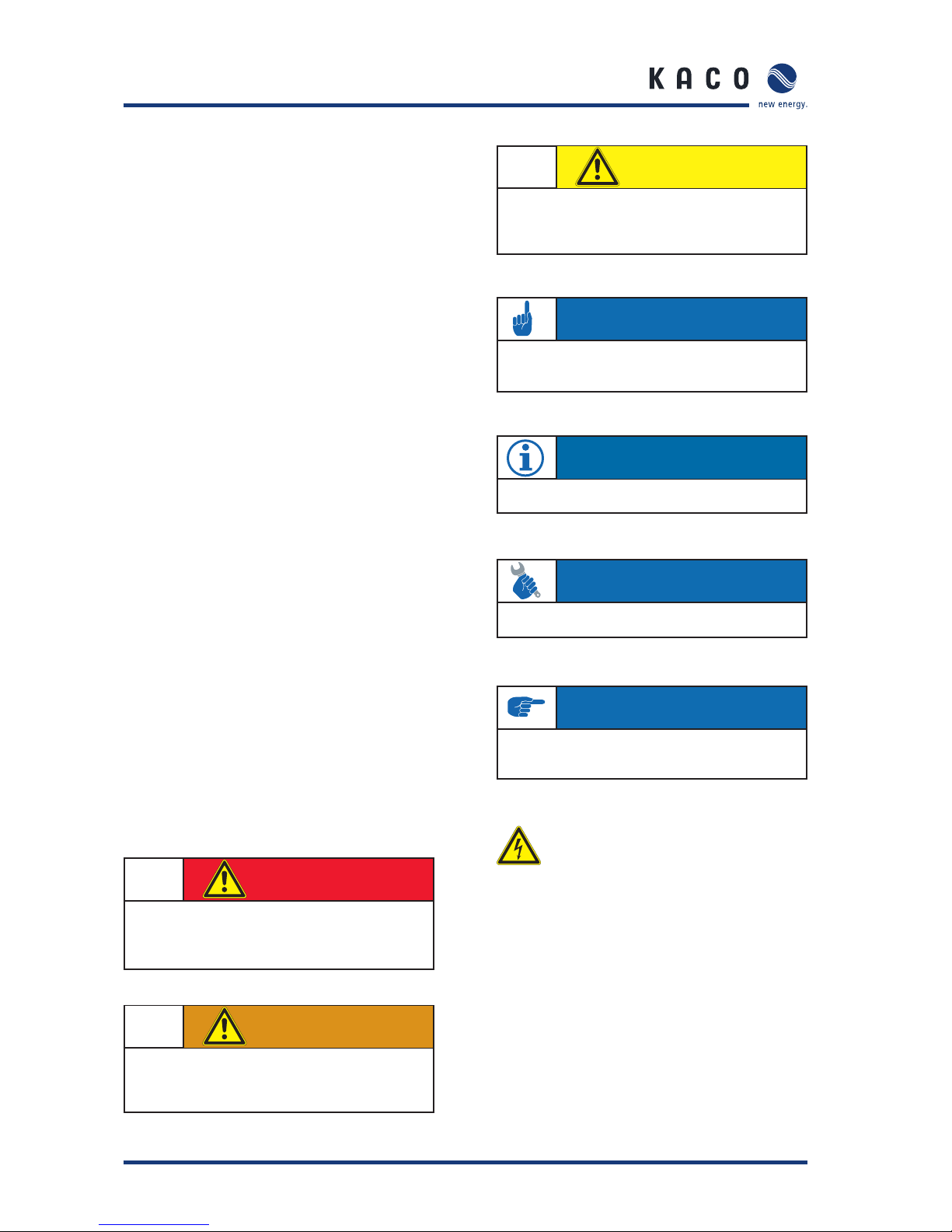
Danger due to lethal voltages.
1.3 CE marking
The CE marking is used to document that the Powador inverter
shown on the name plate fulfi lls the fundamental requirements of the following relevant directives:
Directive concerning electromagnetic compatibility
(Council Directive 2004/108/EC)
Low Voltage Directive
(Council Directive 2006/95/EC).
1.4 Name plate
The name plate showing the exact designation of the unit is
located on the support plate on the underside of the housing.
Section 1 · About This Documentation
DANGER
Failure to observe a warning indicated in this
manner will directly lead to serious bodily injury
or death.
Failure to observe a warning indicated in this
manner may directly lead to serious bodily injury
or death.
WARNING
CAUTION
Failure to observe a warning indicated in this
manner may lead to minor or moderate bodily
injury or to serious damage to property.
AT TE NT I ON
Failure to observe a warning indicated in this manner may
lead to damage to property.
NOTE
Useful information and notes.
AC TI ON
This symbol indicates that a certain action is required.
IMPORTANT
Failure to observe this information may result in reduced
convenience or impaired functionality.
Operating Instructions Powador 2500xi / 3600xi / 4000xi / 4500xi / 5000xi_EN Page 5
2 Safety Instructions
and Regulations
Accident prevention regulations
The inverter must be installed by an authorised electrician,
who is responsible for observing existing standards and regulations.
The proper and safe operation of this unit requires proper
transportation, storage, assembly and installation, as well as
careful operation and maintenance.
The inverter may only be operated by persons who have read
and understood the operating instructions.
Modifi cations
Modifi cations to the inverter are generally prohibited. Always
consult an authorised electrician for modifi cations to the surroundings of the inverter, as they are qualifi ed to undertake
such work.
Transportation
The inverter is subjected to extensive testing and inspections
in our test fi eld. This is how we ensure the high quality of our
products. Our inverters leave our factory in proper electrical
and mechanical condition. Special packaging provides for a
safe and careful transportation. However, transport damage
may still occur. The shipping company is responsible in such
cases.
Thoroughly inspect the inverter upon delivery. If you discover any damage to the packaging which indicates that the
inverter may have been damaged, or if you discover any visible
damage to the inverter, notify the responsible shipping company immediately.
If necessary, your solar installer or KACO new energy GmbH
will assist you. Damage reports must be received by the shipping company in writing within six days of receipt of the
goods.
When transporting the inverter, the original or equivalent
packaging is to be used, as this ensures safe transport.
3 Notes on Installation
and Operation
3.1 Intended use
The unit converts the DC voltage generated by the photovoltaic (PV) modules into AC voltage and feeds this into the
power grid.
Powador inverters are built according to the state of the art
and recognised safety rules. However, improper use may cause
lethal hazards for the operator or third parties, or may result in
damage to the units and other property.
The inverter may only be operated with a permanent connection to the public power grid.
The inverter is not intended for mobile use.
Any other or additional use is not considered the intended use.
The manufacturer/supplier is not liable for damage caused by
such unintended use. Damage caused by such unintended use
is at the sole risk of the operator.
Intended use also includes adherence to the operating and
installation instructions. Your authorised electrician undertakes the registration with your power supply company and
obtains approval for your photovoltaic installation from the
supply grid operator on your behalf. Some of the documents
that you require in order to register your photovoltaic installation and have it approved are included in the installation
instructions.
3.2 Factory warranty and liability
KACO new energy GmbH issues a warranty of seven years on
the Powador inverter starting from the date of installation,
but at most 90 months after shipment by KACO new energy
GmbH.
During this time, KACO new energy GmbH guarantees the
proper operation of the units and to undertake repairs at the
factory free of charge in the event of a defect for which we
are responsible.
Section 2 · Safety Instructions and Regulations
Section 3 · Notes on Installation and Operation
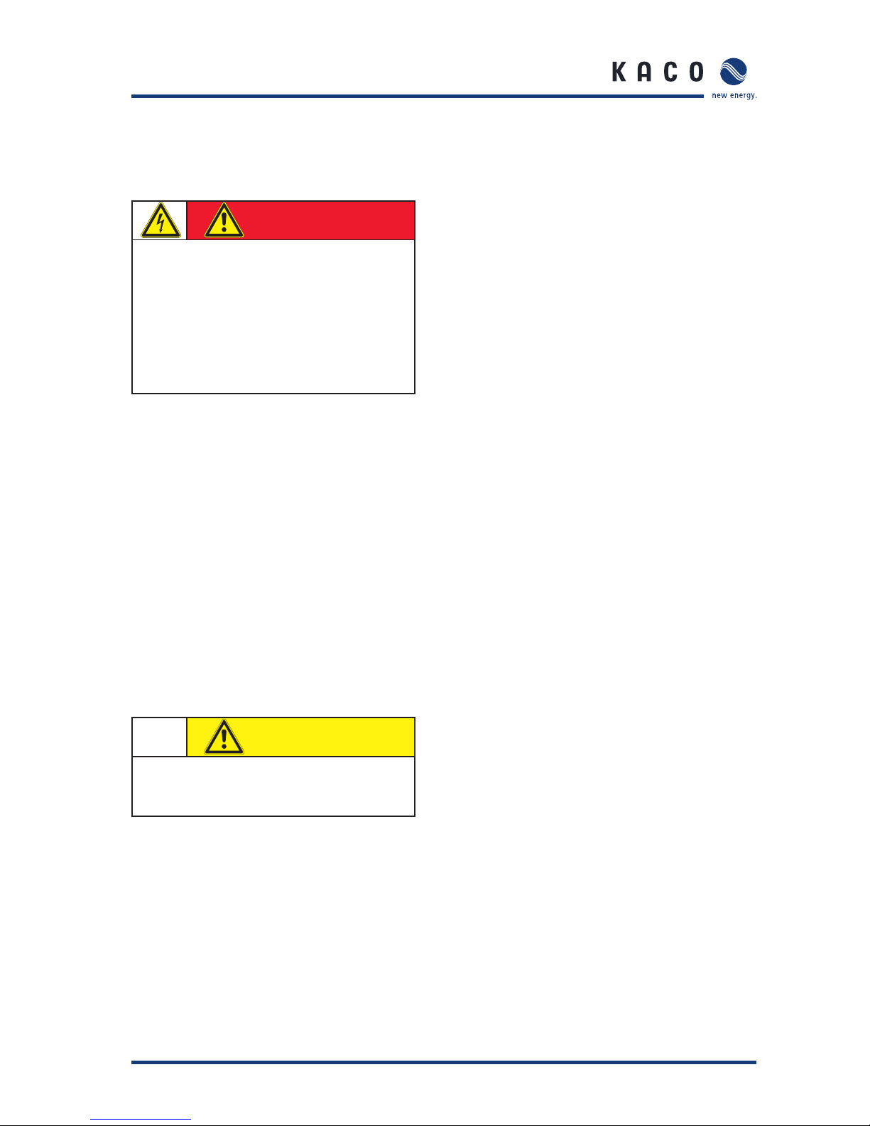
DANGER
Danger due to lethal voltages.
Lethal voltages are present within the unit and
on the power supply lines. Therefore, only skilled
and authorised electricians may install and open
the unit.
Even when the unit is switched off, high contact
voltages may still be present inside the unit.
CAUTION
Risk of damage due to improper modifi cations.
Never modify or manipulate the inverter or other
components of the system.

Page 6 Operating Instructions Powador 2500xi / 3600xi / 4000xi / 4500xi / 5000xi_EN
Contact your specialty dealer or installer if your unit exhibits a
defect or fault during the warranty period.
Warranty claims are excluded in the following cases:
– Use of the units in ways not intended
– Improper installation and installation that does not comply
with standards
– Improper operation
– Operation of units with defective protective equipment
– Unauthorised modifi cations to the units or repair attempts
– Infl uence of foreign objects and force majeure (lightning,
overvoltage, severe weather, fi re)
– Insuffi cient ventilation of the unit
– Failure to observe the relevant safety regulations
– Transport damage.
All warranty claims must be handled at the premises of KACO
new energy GmbH. The unit must, where possible, be returned
in its original or equivalent packaging. The costs for these
services cannot be borne by KACO new energy GmbH.
KACO new energy GmbH will only perform warranty services
if the defective unit is returned to KACO new energy GmbH
together with a copy of the invoice which was issued to the
user by the dealer. The name plate on the unit must be fully
legible. If these requirements are not fulfi lled, KACO new
energy GmbH reserves the right to deny warranty services.
The warranty period for repairs or replacement deliveries is six
months after delivery. However, it continues at least until the
end of the original warranty period for the delivery item.
3.3 Service
We place special emphasis on the quality and longevity of our
inverters, starting with the product development phase. More
than 60 years of experience in the fi eld of current inverters
support us in this philosophy.
However, despite all quality assurance measures, faults may
occur in exceptional cases. In such cases, KACO new energy
GmbH will provide you with the maximum possible support.
KACO new energy GmbH will make every effort to remedy
such faults in an expeditious manner and without a great deal
of bureaucracy. In such cases, contact our service department
directly by telephone at
+49 (0)7132-3818-660
4 Operation
The grid feed process begins in the morning when suffi cient
light is available, and, therefore, when a certain minimum
voltage is present at the inverter. The inverter enables grid
feed after a country-specifi c start-up time (see Installation
Manual, section 4, “Technical Data”).
If, as nightfall approaches, the voltage drops below the
minimum voltage, the grid feed mode ends and the inverter
switches off.
4.1 Overview of controls and displays
Figure 4.1: Overview of the Powador
Legend
1 Display
Displays measured values and confi guration
parameters
2 LED displays
Display the operating status
3 Control keys
Switch between the display and confi guration
of parameters
4 Cable fi tting for AC connection
5 Night start-up button
For activating the display after nightfall
6 DC disconnector
7 RS232 interface
8 Cable feedthrough for RS485 interface cable
9 Cable feedthrough for DC connection
4.2 LED displays
During normal operation, the photovoltaic modules generate
voltage as soon as the insolation is suffi cient. If this voltage is
present in the inverter at a certain level for a certain time, the
inverter begins to feed into the grid.
The inverter is equipped with three LEDs, which give information about the various operating statuses as follows.
Section 3 · Notes on Installation and Operation
Section 4 · Operation
3
2
1
6
7
9
8
5
4
CAUTION
Incorrect use is prohibited.

Operating Instructions Powador 2500xi / 3600xi / 4000xi / 4500xi / 5000xi_EN Page 7
1
2
3
!
ok
Figure 4.2: LED displays
LED (1) (green):
The LED begins to light up beginning with a photovoltaic
module voltage of approx. 300 V and goes out again if the
module voltage is lower than 250 V.
The “OK” LED indicates that the inverter and the inverter control are active. If this LED is not lit, the inverter cannot feed
into the grid.
In normal mode, the LED begins to light up in the morning (if there is enough sunlight) and goes out as nightfall
approaches.
LED (2) (green):
The LED lights up every time the inverter feeds into the grid. For
this to happen, the photovoltaic module voltage must exceed
400 V (factory setting) and suffi cient power must be provided
by the PV generator. If the grid feed is interrupted because the
power is too low, the inverter waits for a country-specifi c length
of time before it begins feeding into the grid once again. LED (2)
can, therefore, light up only when LED (1) is already lit.
In a normal state, the inverter begins feeding into the grid
in the morning and stops feeding into the grid as it becomes
increasingly darker. On cloudy days and in the winter months,
the grid feed can - depending on the PV generator and the
current grid feed power - be temporarily interrupted and subsequently re-started. This process can repeat itself several
times, especially in the morning and evening. This is in no way
an indication of defective operation, but instead constitutes
normal operating behaviour.
LED (3) (red):
The LED indicates that the grid feed was stopped due to a
fault.
The following faults activate the LED (3):
– Grid overvoltage or undervoltage on one of the three
phases
– Failure of one of the phases L2 or L3
– Generator power is too high
– Shutdown due to the temperature being too high
– Fault in the unit
– Leakage current is too high (RCD type B)
– Overfrequency or underfrequency
– Insulation fault
– Communication error
– Fault in the DC grid feed
– Fault in the voltage transformer
– Selftest fault
– Fault in the RCD type B module.
Wait approx. 10 minutes to see if the fault is only temporary
in nature. If this is not the case, notify your authorised electrician.
If the fault is cleared, the grid feed begins once again after a
country-specifi c waiting period (see Installation Instructions,
Section 4, “Technical Data”).
Check whether the fault in question relates to a general power
failure or whether the fuse between the meter and the inverter
has failed. If the fuse has failed, notify your authorised technician. If there was a power failure, simply wait until the fault
has been cleared. The system automatically re-starts.
4.3 Keys “1” and “2”
Figure 4.3: Powador control keys
Key “1” is used to switch between the various displays for
measured values and data. With key “2”, settings such as
those relating to the shutdown value can be confi gured. Here,
menu navigation is divided into two levels. In level 1 (display
mode), measured values such as the solar generator voltage
and yields can be read. Here, only key “1” is activated. In confi guration mode, key “1” is also used to navigate through the
individual displays, and settings are confi gured with key “2”.
Section 4 · Operation
IMPORTANT
If the grid feed phase fails (power failure on the public
grid), LED (3) does not light up. If this happens, all LEDs
and the display go out. The inverter is shut down completely.
The inverter can only resume its normal operation when
the grid feed phase is available once again.
AC TI ON
By pressing key “1” for approx. 1 second, you can choose
which measured value is to be displayed.
The menus are continuous, which means that when you
arrive at the last entry in a menu, the fi rst entry is displayed
once again the next time key “1” is pressed (see Figure
4.4).

Page 8 Operating Instructions Powador 2500xi / 3600xi / 4000xi / 4500xi / 5000xi_EN
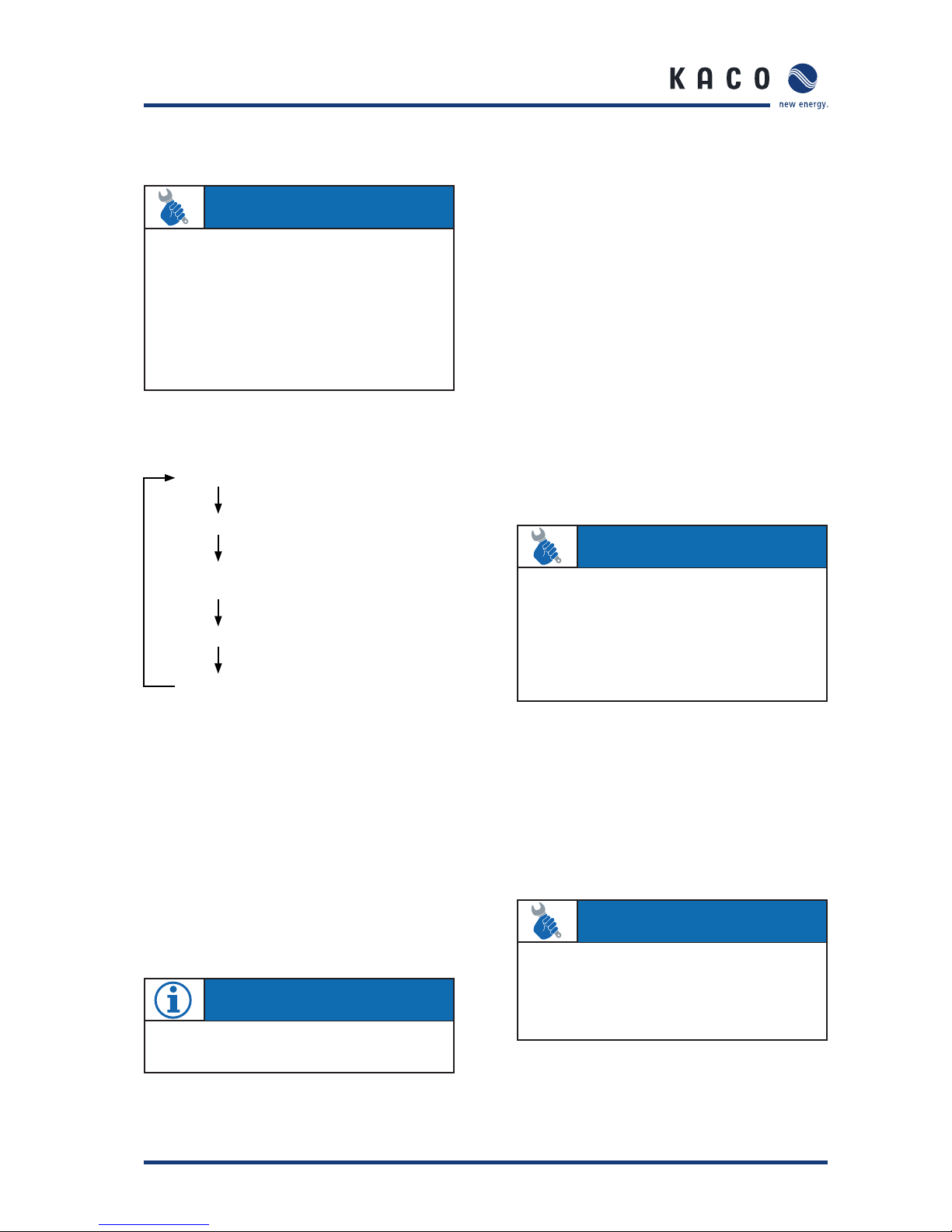
4.4 Level 1 menu - Display menu
The display menu is displayed once the Powador inverter has
started up. Measured values and all of the meters are displayed here. Key “1” is used to navigate through the individual
menu items.
Inverter type display
Start at 410V
Generator voltage (V) and current (A)
Line voltage (V), current (A) and power (W)
Daily peak capacity
Tem perature inside
Counter yield (clear using key “2”)
Yield today
Tot al yield
(Total) economy of CO
2
Counter oper. hours (clear with key “2”)
Operating hours today
Total operating hours
Figure 4.4: Display mode menu
Powador 2500xi / 3600xi / 4000xi / 4500xi / 5000xi
The inverter waits until the voltage exceeds 410 V. One minute later,
the grid feed begins.
The current voltage and current of the solar generator connected to
the inverter.
The current line voltage, line current and the power that is currently
being fed into the grid.
The current day’s peak power (in watts) that was fed into the grid
over a short time.
A display of the current temperature inside the unit, in °C. The
inverter limits the grid feed power depending on the temperature of
the semiconductors.
This meter totals all yields until it is reset again. The customer can
confi gure the time periods for this meter, e.g. as a monthly meter.
The power that has been fed into the grid on the current day in watthours (Wh).
The power that has been fed into the grid since start-up of the
inverter.
Shows the CO
2
savings of this PV installation compared to the
German electricity mix. The CO
2
savings are calculated from the total
yield meter and can also be cleared with this meter.
The customer can confi gure the time periods for this meter, e.g. as
a monthly meter. The procedure for resetting meters is explained at
the bottom of the page.
Today’s hours of operation. As soon as the inverter is in standby
mode (i.e. when LED (1) lights up), the running time is added up.
Hours of operation since start-up of the inverter. As soon as the
inverter is in standby mode (i.e. when LED (1) lights up), the running
time is added up.
Explanation of the menu items in display mode
Section 4 · Operation
“Counter yield” and “Counter oper. hours” can be cleared separately from the other meters. When “Counter yield” or “Counter
oper. hours” is displayed, you can reach the “Clear counter?” display by pressing key “2”. Key “2” must now be used to select “yes”. Press
key “1” to confi rm the clearing. The display jumps back to the meter that was cleared. “Counter yield” and the “Counter oper. hours”
are always cleared together. Therefore, clearing one meter suffi ces to clear both.
Operating Instructions Powador 2500xi / 3600xi / 4000xi / 4500xi / 5000xi_EN Page 9
4.5 Level 2 menu - Confi guration mode
Software version
Clear the grid feed meter
Select the interface and confi guration of
the RS485 address
S0 interface pulse rate
Immediate start
Figure 4.5: Confi guration mode menu
Clearing the grid feed meter
When the grid feed meter is cleared, all meters (“Counter
yield”, “Yield today”, “Total yield”, “Economy of CO
2
”, “Dail y
peak capacity”, “Counter oper. hours”, “Operating hours
today”, “Total operating hours”) are reset to zero.
To clear the meters, select “Yes” with key “2”, and confi rm
your selection by pressing key “1”. The required code is “2”
and is entered using key “2”. By means of an additional confi rmation with key “1”, all meters are cleared. A display indicating that the grid feed counters have been cleared confi rms
this action.
Choice of interface and address setting
Using the menu item “Interface”, you can use key “2” to
switch between the RS232 and RS485 interfaces.
If the RS485 interface is activated, you can reach the address
setting by pressing key “1”. By pressing key “2”, the address
can be set in a consecutive manner from 1 to 32.
The address then jumps back to 1. The RS485 interface is used
to communicate with the Powador-proLOG. When several
inverters are connected to a Powador-proLOG, each address
may only be used once. It is, therefore, possible to monitor 32
Powador inverters with one Powador-proLOG.
S0 interface pulse rate
The S0 interface is designed as a galvanically isolated transistor output. This interface is designed according to “DIN 43864
- Current interface for transmitting pulses from a pulsing meter
to a tariff metering device”.
The S0 interface pulse rate can be chosen in three unit intervals: 500, 1000 and 2000 pulses/kWh. Due to these tolerances, the emitted pulse yield may deviate from the values
on your supply grid operator’s grid feed meter by up to 15 %.
Immediate start
The inverter can also be started up without any waiting period
for the purpose of testing or for the purpose of acceptance by
your power supply company.
If the inverter is already feeding into the grid, this menu item
is not available.
Section 4 · Operation
AC TI ON
To switch to confi guration mode, keep key “1” pressed
down while at the same time pressing key “2”, until the
software version is displayed in the confi guration mode.
Pressing key “1” now switches to the next menu item,
and changes can be made in the respective menu item by
pressing key “2”. The set value increases each time key
“2” is pressed. If the maximum value has been reached,
the value jumps to the minimum setting choice. The various settings are highlighted in fi gure 4.5.
NOTE
Meters can only be cleared.It is not possible to set the
meters.
AC TI ON
Settings are saved only upon exiting confi guration mode.
If 2 minutes elapse without a key being pressed, the confi guration mode is automatically exited. The confi guration mode can also be immediately exited by pressing
both keys. As a confi rmation, “Settings saved” appears
on the display for 4 seconds. The settings are now permanently saved in the Powador inverter.
AC TI ON
Keep key “2” pressed down for a short time until the
inverter switches on (relays switch audibly) and the green
grid feed LED (2) lights up. If there is insuffi cient solar
generator power, the inverter stops feeding into the grid
after a short period of time.

Page 10 Operating Instructions Powador 2500xi / 3600xi / 4000xi / 4500xi / 5000xi_EN
4.6 DC disconnector
Figure 4.6: Underside of the Powador
The inverters include an internal DC disconnector, which
allows for the inverter to be disconnected from the photovoltaic generator in case of repair or fault.
To disconnect the inverter from the photovoltaic generator,
turn the internal DC disconnector on the underside of the
inverter from the ON (1) position to the OFF (0) position (see
fi gure 4.6).
When delivered, the inverter’s internal DC disconnector is in
the OFF (0) position.
4.7 Night start-up key
The unit switches off in the evening as nightfall approaches.
The display is no longer shown. In order to retrieve the values
from the current day, (daily yield, daily hours of operation and
max. grid feed power) after the display switches off, the unit
can also be activated during the night by pressing the night
start-up key on the underside of the inverter.
You can now scroll through the menu and retrieve the saved
values. If over one minute elapses without a key being pressed,
the unit switches off automatically once again.
The “Counter oper. hours ”, “Total operating hours”, “Counter yield”, and “Total yield” data are permanently saved and
totaled. This data remains in memory even if the inverter is
switched off for a long time.
The daily yield, daily hours of operation and the max. daily grid
feed power are available until the following morning and are
cleared when PV generator voltage is present again.
4.8 The serial RS232 interface
Operating data can be transmitted to a computer (e.g. notebook)
over a galvanically isolated serial interface (see fi gure 4.6 - (7))
from where it can then be individually processed further using
standard spreadsheet software.
A standard serial 1:1 interface cable is all that is required for
connecting the inverter to the computer. The cable length
should not exceed 20 metres.
The data from the inverter is sent unidirectionally as pure
ASCII text over the serial interface. The data is not checked
for errors.
Tab le 4.1: RS232 interface pin assignment
The RS232 interface has the following parameters:
Baud rate Data bits Parity Stop bits Protocol
9600 baud 8 none 1 none
Figure 4.7 shows, as an example, a few of lines of transmission via the RS232 interface.
Data can be received with any terminal emulator, which comes
with every operating system, or with the KACO-viso visualisation tool.
Together with the Powador inverter, KACO-viso takes over the
role of a data logger. It saves the data from the inverter and
displays it in various diagram types as a daily or monthly representation.
The PC, however, must also run continuously. Because of the
amount of energy used, this type of monitoring only makes
sense over limited periods, such as during a fault analysis. For
permanent monitoring, we recommend the optional accessories (see section 5).
Section 4 · Operation
6
5
7
Powador Sub-D
male 9-polig
Bedeutung PC Sub-D
female 9-polig
2TXD 2
3RXD3
4RTS 4
5GND5
Signifi cation
male 9-pole female 9-pole
AC TI ON
To do this, press the “night start-up” key (see fi gure 4.6
- (6)) on the underside of the unit for approx. 5 seconds
until a display appears.
NOTE
The KACO-viso visualisation software can be downloaded from
http://www.kaco-newenergy.de
NOTE
With the optional accessories (see section 5), you can
also implement wireless data transmission over long distances between the inverter and your PC.
Operating Instructions Powador 2500xi / 3600xi / 4000xi / 4500xi / 5000xi_EN Page 11
Section 4 · Operation
Tab le 4. 2: Explanation of the individual columns
Figure 4.7: Excerpt from the protocol of a transmission via the RS232 interface
The interface of the PC or laptop that is connected must
comply with the standard for RS232 interfaces. Some computer manufacturers do not fully adhere to the standard. In such
cases, problems may occur during data transmissions.
4.9 The RS485 interface
Powador inverters are also equipped with an RS485 interface
(see Installation Instructions, fi gure 6.7) in order to enable
remote monitoring of your photovoltaic installation. Several
inverters can be monitored over this interface at the same
time. Using the Powador-proLOG series, you can receive yield
and operating data as well as error messages by SMS (text
message) or e-mail. This monitoring option is especially recommended for situations where you are unable to check the
functionality of the installation on-site at regular intervals,
e.g. if you live far away from the installation site.
In addition, you can use the Powador link within your installation to bridge long distances between several inverters or
between an inverter and the Powador-proLOG by means of a
wireless radio transmission. Contact your installer if you wish
to integrate remote monitoring into your system.
4.10 Display
Inverters in the Powador xi series are equipped with a backlit LCD (see fi gure 4.1 - (1)) which displays measured values
and data.
In normal mode, the backlighting is switched off. As soon
as you press one of the keys, the backlighting is activated.
If approx. 1 minute elapses without a key being pressed, it
switches off once again.
Spalte 1 2 3 4 5 6 7 8 9 10
00.00.0000 00:05:30 4 363.8 0.37 134 226.1 0.53 103 23
00.00.0000 00:05:40 4 366.0 0.39 142 226.1 0.53 112 23
00.00.0000 00:05:50 4 359.5 0.41 147 226.1 0.53 116 23
00.00.0000 00:06:00 4 369.8 0.42 155 226.1 0.58 118 23
00.00.0000 00:06:10 4 377.0 0.43 162 226.1 0.63 131 23
00.00.0000 00:06:20 4 373.6 0.45 168 226.1 0.63 133 23
00.00.0000 00:06:30 4 364.0 0.48 174 226.1 0.68 146 23
00.00.0000 00:06:40 4 364.3 0.49 178 226.1 0.68 146 23
Column
NOTE
The measured data for current and voltage istainted with
the specifi ed tolerances (see Installation Instructions).This
data is not suitable for measuring effi ciency or compiling
yield data.Its sole purpose is to monitor the basic operation of the system.
IMPORTANT
Due to measuring tolerances, the measured values may
not always correspond to the actual values. The inverter’s
measuring elements have been selected to ensure maximum solar yields.
Due to these tolerances, the daily yields displayed on the
inverter may deviate from the values on your supply grid
operator’s grid feed meter by up to 15 %.
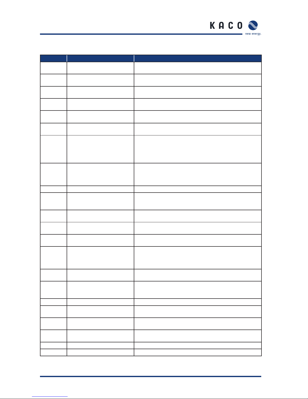
Column Explanation Column Explanation
1 Not in use 6 Generator power in W
2 Daily operating time 7 Grid voltage in V
3 Operating mode (see table 4.3) 8 Grid current, delivered current in A
4 Generator voltage in V 9 Grid-feeding power in W
5 Generator current in A 10 Device temperature in °C
Page 12 Operating Instructions Powador 2500xi / 3600xi / 4000xi / 4500xi / 5000xi_EN
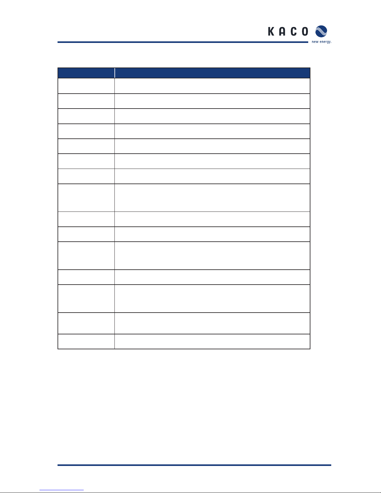
Operating statuses
Status Explanation Comment
0 Inverter has just switched on Only for a brief time after the inverter fi rst switches on in the
morning.
1 Waiting to start Selftest is complete, the Powador will switch to grid feed mode in a
few seconds.
2 Waiting to switch off Generator voltage and power is too low. The status before it changes
over to night shutdown mode.
3 Constant voltage regulator When the grid feed begins, a constant generator voltage is fed in
(80 % of the measured no-load voltage) for a short period.
4 MPP regulator, constant search
movement
In cases of low insolation, the grid is fed into while the MPP regulator is searching.
5 MPP regulator, without search
movement
In cases of high insolation, the grid is fed into while the MPP regulator is stationary so as to maximise yields.
6 Wait mode before grid feed, test-
ing the grid and solar voltage
The inverter has stopped the grid feed because the power of the PV
modules is too low (e.g. twilight). If the generator voltage is higher
than the switch-on threshold (410 V), the inverter begins the grid feed
once again after a country-specifi c waiting period (see Installation
Instructions, section 4, Technical Data).
7 Wait mode before selftest, testing
the line and solar voltage
The inverter waits until the generator voltage exceeds the switch-on
threshold and begins the selftest of the relays after a country-specifi cwaiting period (see Installation Instructions, section 4, Technical
Data).
8 Selftest of the relays Testing line relays prior to beginning grid feed.
10 Overtemperature shutdown If the inverter overheats (heat sink temperature >85 °C) due to the
ambient temperature being too high and inadequate air circulation,
the inverter switches off.
11 Power limitation Protective function of the inverter when too much generator power
is supplied or the heat sink of the unit exceeds 75 °C.
12 Overload shutdown Protective function of the inverter when too much generator power
is supplied.
13 Overvoltage shutdown Protective function of the inverter when the line voltage L1 is too
high.
14 Line failure (3-phase monitoring) Protective function of the inverter when the measured values of one
of the three grid phases are beyond the permitted tolerance.
Reasons for line failures are: undervoltage, overvoltage, underfrequency, overfrequency, a fault in the phase conductor.
15 Changing over to night shutdown
mode
Inverter switches from stand-by to night shutdown mode.
18 RCD type B shutdown Residual current is too high, the integrated AC/DC-sensitive residual
current circuit breaker has registered an unduly high leakage current
to the PE.
19 Insulation resistance too low Insulation resistance from PV-/PV+ to PE <1.2 MOhm.
30 Fault in the voltage transformer The current and voltage measurements in the inverter are not plau-
sible.
31 Fault in the RCD type B module A fault has occurred in the AC/DC-sensitive residual current circuit
breaker.
32 Selftest error An error has occurred during the line relay test, a line relay is not
functioning correctly.
33 Fault in the DC grid feed The DC feed into the grid was too large.
34 Communication error An error has occurred in the internal data transmission.
Tab le 4. 3: Explanation of the operating states
Section 4 · Operation
Operating Instructions Powador 2500xi / 3600xi / 4000xi / 4500xi / 5000xi_EN Page 13
Section 4 · Operation
Display Explanation
Line failure
Undervoltage Lx
The voltage of a grid phase is too low, the grid cannot be fed into. The phase in which
the fault occurs (undervoltage) is displayed in each case.
Line failure
Overvoltage Lx
The voltage of a grid phase is too high, the grid cannot be fed into. The phase in
which the fault occurs (overvoltage) is displayed in each case.
Line failure
Phase conductor
The phase shifts of the phase voltages are incorrect. A proper three-phase supply
network is not present.
Line error
overvoltage L1
Overvoltage shutdown due to a voltage boost caused by increased line impedance of
the grid connection L1.
Line failure
Underfrequency
The line frequency is too low.
Line failure
Overfrequency
The line frequency is too high.
Error
DC grid feeding
The DC feed into the grid has exceeded the permitted limit value. This grid feed can
be impressed from the grid on the Powador inverter so that no inverter fault exists.
Error current
switch-off
The current and voltage measurements in the inverter are not plausible. This can be
caused by very dynamic weather conditions, if there are quick changes between low
grid feed power (e.g. 200 W) and high grid feed power (e.g. the inverter’s maximum
grid feed power).
Error
RCD module
An operational fault has occurred in the AC/DC-sensitive residual current circuit
breaker.
Error
Selftest
The internal grid separation relay test has failed.
Error
Measurement
The current and voltage measurements in the inverter are not plausible. This can be
caused by very dynamic weather conditions if there are quick changes between low
grid feed power (e.g. 200 W) and high grid feed power (e.g. the maximum grid feed
power).
Error isolation
generator
The insulation resistance on the DC side is <1.2 MOhm. The grid cannot be fed into.
The insulation resistance of the PV modules must be tested.
Temperature to o
high inside
The temperature in the unit has become too high (>85 °C). Starting from an internal
temperature of 75 °C, the inverter limits the power and levels off between 75 °C
and 80 °C.An internal temperature of 85 °C is only achieved if convection cooling is
impeded by external factors, e.g. by covering the cooling fi ns.
Failure
PV overvoltage
The power of the modules was too high for a short time. This can occur during times
of very dynamic weather conditions. The power limiter usually prevents too much
power at the input of the inverter so that the inverter does not shut down.
Line failure
Average voltage
The average line voltage measurement over a 10 minute period according to EN
50160 has exceeded the maximum permitted limit value.
Tab le 4. 4:
Fault signals
Fault signals
Page 14 Operating Instructions Powador 2500xi / 3600xi / 4000xi / 4500xi / 5000xi_EN
Fault signals
When these error messages are displayed, the grid feed is
interrupted, the red LED (3) lights up, and the fault signal relay
has switched. This error correction takes a country-specifi c
length of time (see Installation Instructions, section 4, Technical Data). Afterwards the red fault LED (3) goes out, the
fault signal relay drops out again, and the display signals that
it is ready to feed into the grid once again. If the fault is no
longer present, the Powador inverter begins feeding into the
grid once again after a preset waiting period (see Installation
Instructions, section 4, Technical Data).
Many of these fault signals point to a fault in the grid, and are,
therefore, not an operational fault on the part of the Powador inverter. The minimum triggering levels are determined
by applicable standards (e.g. VDE0126-1-1), and the inverter
must switch off if the permitted values are exceeded.
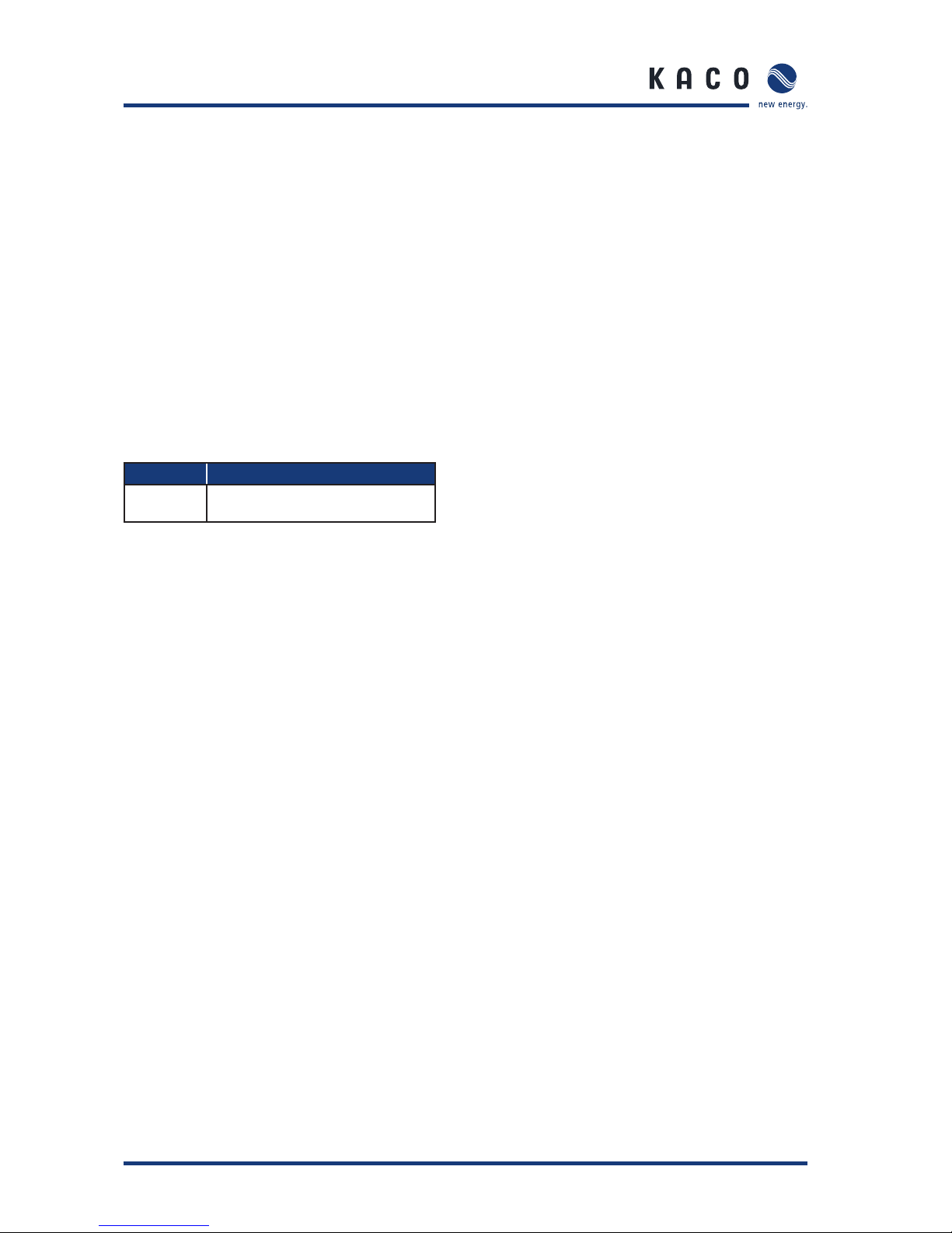
Automatic display during operation
Tab le 4.5: Display
Display Explanation
Selftest
in progress
The grid separation relays are tested
for proper operation.
Section 4 · Operation
 Loading...