

Page 1
SERVICE MANUAL
MB665<Rev.004>20089SERVICE MANUAL
UX-G300B, UX-G300E, UX-G300EN, UX-G300EV,
UX-G303E, UX-G303EN, UX-G303EV, UX-G305E,
UX-G305EN, UX-G305EV, UX-G300A, UX-G300US,
MICRO COMPONENT SYSTEM
UX-G300UF, UX-G300UT, UX-G300UW,
UX-G300UG, UX-G300UN, UX-G305UT
CA-UXG300
SP-UXG300
COPYRIGHT © 2008 Victor Company of Japan, Limited
Lead free solder used in the board (material : Sn-Ag-Cu, melting point : 219 Centigrade)
Lead free solder used in the board (material : Sn-Cu, melting point : 230 Centigrade)
SP-UXG300
UX-G300EV
UX-G303EV
UX-G305EV
1 PRECAUTION. . . . . . . . . . . . . . . . . . . . . . . . . . . . . . . . . . . . . . . . . . . . . . . . . . . . . . . . . . . . . . . . . . . . . . . . . 1-4
2 SPECIFIC SERVICE INSTRUCTIONS . . . . . . . . . . . . . . . . . . . . . . . . . . . . . . . . . . . . . . . . . . . . . . . . . . . . . . 1-7
3 DISASSEMBLY . . . . . . . . . . . . . . . . . . . . . . . . . . . . . . . . . . . . . . . . . . . . . . . . . . . . . . . . . . . . . . . . . . . . . . . 1-7
4 ADJUSTMENT . . . . . . . . . . . . . . . . . . . . . . . . . . . . . . . . . . . . . . . . . . . . . . . . . . . . . . . . . . . . . . . . . . . . . . . 1-20
5 TROUBLESHOOTING . . . . . . . . . . . . . . . . . . . . . . . . . . . . . . . . . . . . . . . . . . . . . . . . . . . . . . . . . . . . . . . . . 1-21
COPYRIGHT © 2008 Victor Company of Japan, Limited
TABLE OF CONTENTS
No.MB665<Rev.004>
2008/9
Page 2

SPECIFICATION
UX-G300 B/E/EN/EV
UX-G303 E/EN/EV
UX-G305 E/EN/EV
Amplifier section
OUTPUT POWER 60 W (30 W + 30 W) at 4 Ω (10% THD)
Speakers/Impedance 4 Ω - 16 Ω
Audio input AUDIO IN 500 mV/47 kΩ (at “IN LVL1”)
250 mV/47 kΩ (at “IN LVL2”)
125 mV/47 kΩ (at “IN LVL3”)
Digital input USB MEMORY
Tuner section
FM tuning range 87.50 MHz - 108.00 MHz
AM (MW) tuning range 522 kHz - 1 629 kHz
CD player section
Dynamic range 88 dB
Signal-to-noise ratio 85 dB
Wow and flutter Immeasurable
USB storage
USB specification Compatible with USB 2.0 Full Speed
Compatible device Mass storage class
Compatible file system "FAT16,FAT32"
Bus power supply Max. 500 mA
Speakers
Speaker units 10 cm cone x 1
Impedance 4 Ω
Dimensions (approx.) 160 mm x 250 mm x 150 mm (W/H/D)
Mass (approx.) 1.6 kg each
General
Power requirements "AC 230~,50 Hz"
Power supply to USB mass storage class device DC 5 V =500 mA
Power consumption 20 W (power on)
6.5 W (standby mode)
1 W or less (Save Mode)
Dimensions (W x H x D) 165 mm x 251 mm x 269 mm
Mass 2.6 kg
Specifications and appearance are subject to change without prior notice.
1-2 (No.MB665<Rev.004>)
Page 3

UX-G300 US/UN/UB/UG/A/UW/UF/UT
UX-G305UT
Amplifier section
OUTPUT POWER 60 W (30 W + 30 W) at 4 Ω (10% THD)
Speakers/Impedance 4 Ω - 16 Ω
Audio input AUDIO IN 500 mV/47 kΩ (at “IN LVL1”)
250 mV/47 kΩ (at “IN LVL2”)
125 mV/47 kΩ (at “IN LVL3”)
Digital input USB MEMORY
Tuner section
FM tuning range 87.50 MHz - 108.00 MHz
AM (MW) tuning range 530 kHz - 1 710 kHz (in 10 kHz spacing)
531 kHz - 1 710 kHz (in 9 kHz spacing)
CD player section
Dynamic range 88 dB
Signal-to-noise ratio 85 dB
Wow and flutter Immeasurable
USB storage
USB specification Compatible with USB 2.0 Full Speed
Compatible device Mass storage class
Compatible file system FAT16, FAT32
Bus power supply Max. 500 mA
Speakers
Speaker units 10 cm cone x 1
Impedance 4 Ω
Dimensions (approx.) 160 mm x 250 mm x 150 mm (W/H/D)
Mass (approx.) 1.6 kg each
General
Power requirements AC 110 V - AC 240 V , 50/60 Hz
AC 240 V , 50 Hz (only Australia)
AC 220 V , 50 Hz (only Hong Kong)
Power supply to USB mass storage class device DC 5 V =500 mA
Power consumption 20 W (power on)
6.5 W (standby mode)
1 W or less (Save Mode)
Dimensions (W x H x D) 165 mm x 251 mm x 269 mm
Mass 2.6 kg
Specifications and appearance are subject to change without prior notice.
(No.MB665<Rev.004>)1-3
Page 4
SECTION 1
PRECAUTION
1.1 Safety Precautions
(1) This design of this product contains special hardware and
many circuits and components specially for safety purposes. For continued protection, no changes should be made
to the original design unless authorized in writing by the
manufacturer. Replacement parts must be identical to
those used in the original circuits. Services should be performed by qualified personnel only.
(2) Alterations of the design or circuitry of the product should
not be made. Any design alterations of the product should
not be made. Any design alterations or additions will void
the manufacturers warranty and will further relieve the
manufacture of responsibility for personal injury or property
damage resulting therefrom.
(3) Many electrical and mechanical parts in the products have
special safety-related characteristics. These characteristics are often not evident from visual inspection nor can the
protection afforded by them necessarily be obtained by using replacement components rated for higher voltage, wattage, etc. Replacement parts which have these special
safety characteristics are identified in the Parts List of Service Manual. Electrical components having such features
are identified by shading on the schematics and by ( ) on
the Parts List in the Service Manual. The use of a substitute
replacement which does not have the same safety characteristics as the recommended replacement parts shown in
the Parts List of Service Manual may create shock, fire, or
other hazards.
(4) The leads in the products are routed and dressed with ties,
clamps, tubings, barriers and the like to be separated from
live parts, high temperature parts, moving parts and/or
sharp edges for the prevention of electric shock and fire
hazard. When service is required, the original lead routing
and dress should be observed, and it should be confirmed
that they have been returned to normal, after reassembling.
(5) Leakage shock hazard testing
After reassembling the product, always perform an isolation check on the exposed metal parts of the product (antenna terminals, knobs, metal cabinet, screw heads,
headphone jack, control shafts, etc.) to be sure the product
is safe to operate without danger of electrical shock.Do not
use a line isolation transformer during this check.
• Plug the AC line cord directly into the AC outlet. Using a
"Leakage Current Tester", measure the leakage current
from each exposed metal parts of the cabinet, particularly any exposed metal part having a return path to the
chassis, to a known good earth ground. Any leakage current must not exceed 0.5mA AC (r.m.s.).
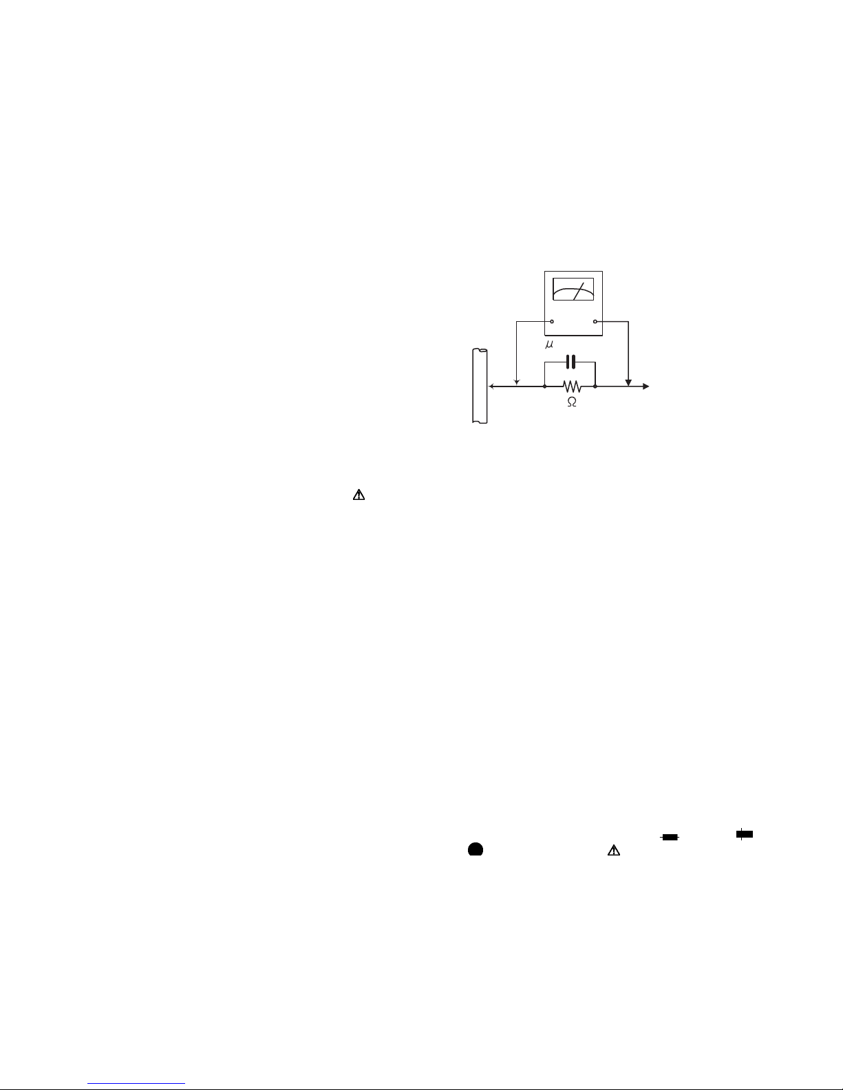
• Alternate check method
Plug the AC line cord directly into the AC outlet. Use an
AC voltmeter having, 1,000Ω per volt or more sensitivity
in the following manner. Connect a 1,500Ω 10W resistor
paralleled by a 0.15µF AC-type capacitor between an ex-
posed metal part and a known good earth ground.
Measure the AC voltage across the resistor with the AC
voltmeter.
Move the resistor connection to each exposed metal
part, particularly any exposed metal part having a return
path to the chassis, and measure the AC voltage across
the resistor. Now, reverse the plug in the AC outlet and
repeat each measurement. Voltage measured any must
not exceed 0.75 V AC (r.m.s.). This corresponds to 0.5
mA AC (r.m.s.).
AC VOLTMETER
(Having 1000
ohms/volts,
or more sensitivity)
0.15 F AC TYPE
Place this
probe on
1500 10W
Good earth ground
1.2 Warning
(1) This equipment has been designed and manufactured to
meet international safety standards.
(2) It is the legal responsibility of the repairer to ensure that
these safety standards are maintained.
(3) Repairs must be made in accordance with the relevant
safety standards.
(4) It is essential that safety critical components are replaced
by approved parts.
(5) If mains voltage selector is provided, check setting for local
voltage.
1.3 Caution
Burrs formed during molding may be left over on some parts
of the chassis.
Therefore, pay attention to such burrs in the case of preforming repair of this system.
1.4 Critical parts for safety
In regard with component parts appearing on the silk-screen
printed side (parts side) of the PWB diagrams, the parts that are
printed over with black such as the resistor ( ), diode ( )
and ICP ( ) or identified by the " " mark nearby are critical
for safety. When replacing them, be sure to use the parts of the
same type and rating as specified by the manufacturer.
(This regulation dose not Except the J and C version)
each exposed
metal part.
1-4 (No.MB665<Rev.004>)
Page 5
1.5 Preventing static electricity
Electrostatic discharge (ESD), which occurs when static electricity stored in the body, fabric, etc. is discharged, can destroy the laser
diode in the traverse unit (optical pickup). Take care to prevent this when performing repairs.
1.5.1 Grounding to prevent damage by static electricity
Static electricity in the work area can destroy the optical pickup (laser diode) in devices such as laser products.
Be careful to use proper grounding in the area where repairs are being performed.
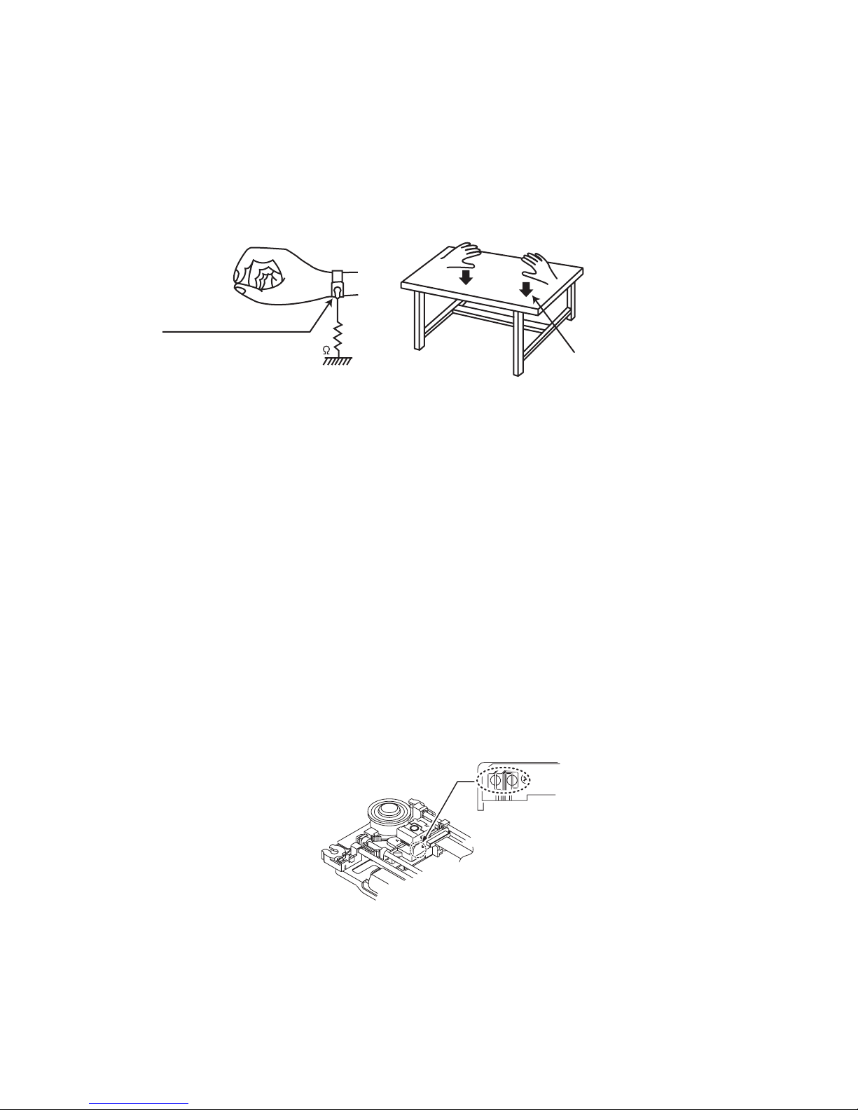
(1) Ground the workbench
Ground the workbench by laying conductive material (such as a conductive sheet) or an iron plate over it before placing the
traverse unit (optical pickup) on it.
(2) Ground yourself
Use an anti-static wrist strap to release any static electricity built up in your body.
(caption)
Anti-static wrist strap
1M
Conductive material
(conductive sheet) or iron palate
(3) Handling the optical pickup
• In order to maintain quality during transport and before installation, both sides of the laser diode on the replacement optical
pickup are shorted. After replacement, return the shorted parts to their original condition.
(Refer to the text.)
• Do not use a tester to check the condition of the laser diode in the optical pickup. The tester's internal power source can easily
destroy the laser diode.
1.6 Handling the traverse unit (optical pickup)
(1) Do not subject the traverse unit (optical pickup) to strong shocks, as it is a sensitive, complex unit.
(2) Cut off the shorted part of the flexible cable using nippers, etc. after replacing the optical pickup. For specific details, refer to the
replacement procedure in the text. Remove the anti-static pin when replacing the traverse unit. Be careful not to take too long a
time when attaching it to the connector.
(3) Handle the flexible cable carefully as it may break when subjected to strong force.
(4) I t is not possible to adjust the semi-fixed resistor that adjusts the laser power. Do not turn it.
1.7 Attention when traverse unit is decomposed
*Please refer to "Disassembly method" in the text for the pickup unit.
• Apply solder to the short land sections before the card wire is disconnected from the connecto on the servo board. (If the card wire
is disconnected without applying solder, the pickup may be destroyed by static electricity.)
• In the assembly, be sure to remove solder from the short land sections after connecting the card wire.
Solder short land section
(No.MB665<Rev.004>)1-5
Page 6
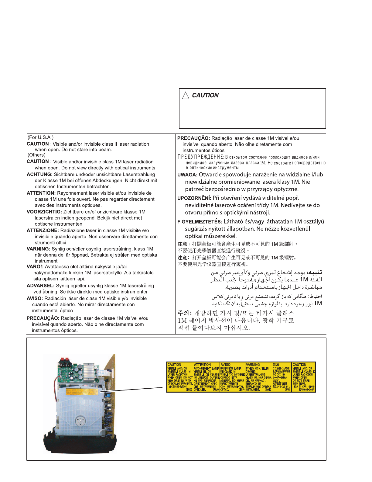
1.8 Important for laser products
1.CLASS 1 LASER PRODUCT
2.CAUTION :
(For U.S.A.) Visible and/or invisible class II laser radiation
when open. Do not stare into beam.
(Others) Visible and/or invisible class 1M laser radiation
when open. Do not view directly with optical instruments.
3.CAUTION : Visible and/or invisible laser radiation when
open and inter lock failed or defeated. Avoid direct
exposure to beam.
4.CAUTION : This laser product uses visible and/or invisible
laser radiation and is equipped with safety switches which
prevent emission of radiation when the drawer is open and
the safety interlocks have failed or are defeated. It is
dangerous to defeat the safety switches.
5.CAUTION : If safety switches malfunction, the laser is able
to function.
6.CAUTION : Use of controls, adjustments or performance of
procedures other than those specified here in may result in
hazardous radiation exposure.
!
Please use enough caution not to
see the beam directly or touch it
in case of an adjustment or operation
check.
REPRODUCTION AND POSITION OF LABELS and PRINT
WARNING LABEL and PRINT
1-6 (No.MB665<Rev.004>)
Page 7
SECTION 2
A
A
SPECIFIC SERVICE INSTRUCTIONS
New CD mechanism was added.
In a model using new CD mechanism for, it stick a blue label for identification on the back side.
When it repair the CD mechanism of an article sticking this label on, please use a parts list of FMU-VK1-2M.
label for identification
SECTION 3
DISASSEMBLY
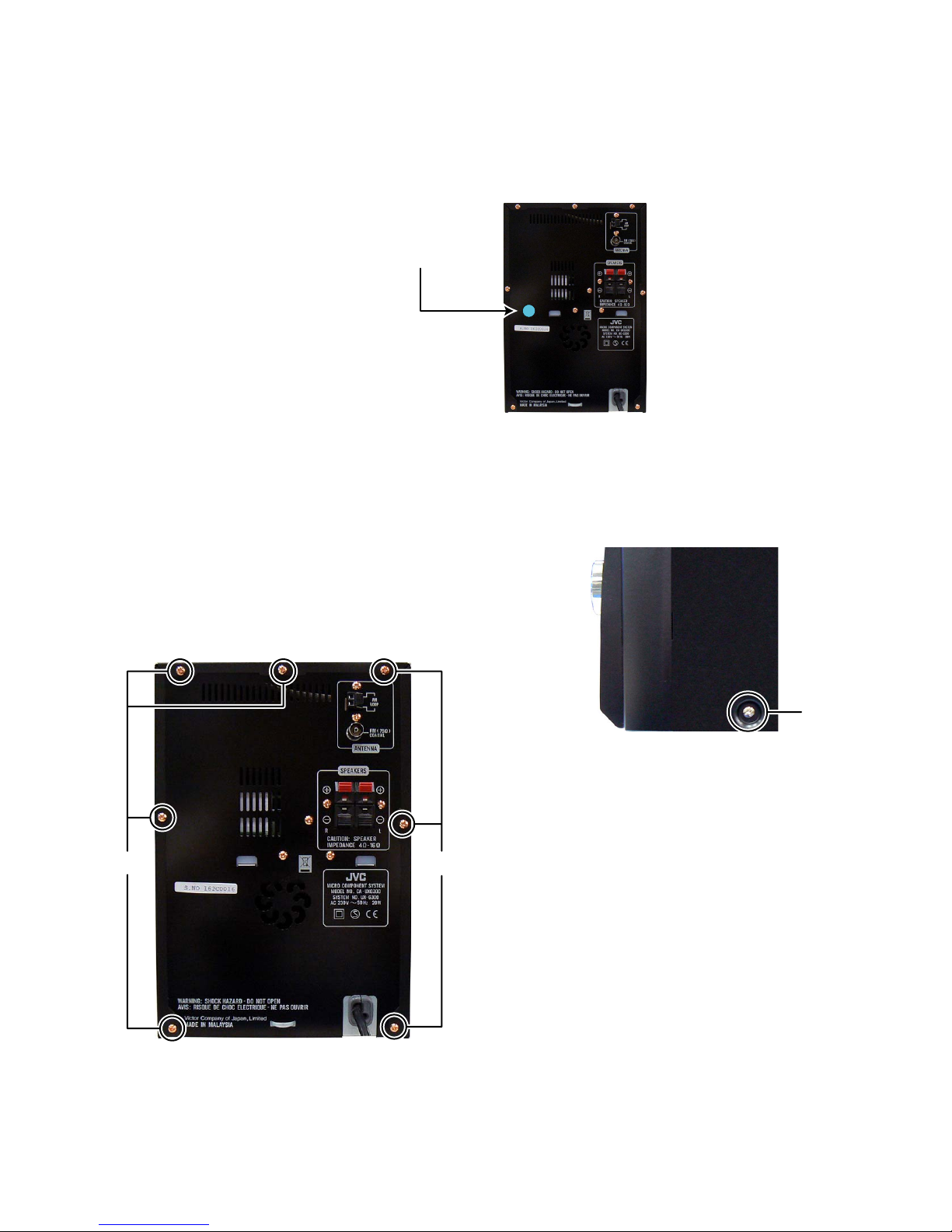
3.1 Main body (Used figure are UX-G300E)
3.1.1 Removing the Metal Cover (See Fig.1, 2)
(1) Remove the seven screws A attaching the Metal cover.
(See Fig.1)
(2) Remove the two screws B attaching the both side of the
Metal cover. (See Fig.2)
A
B
Fig.2
Fig.1
(No.MB665<Rev.004>)1-7
Page 8
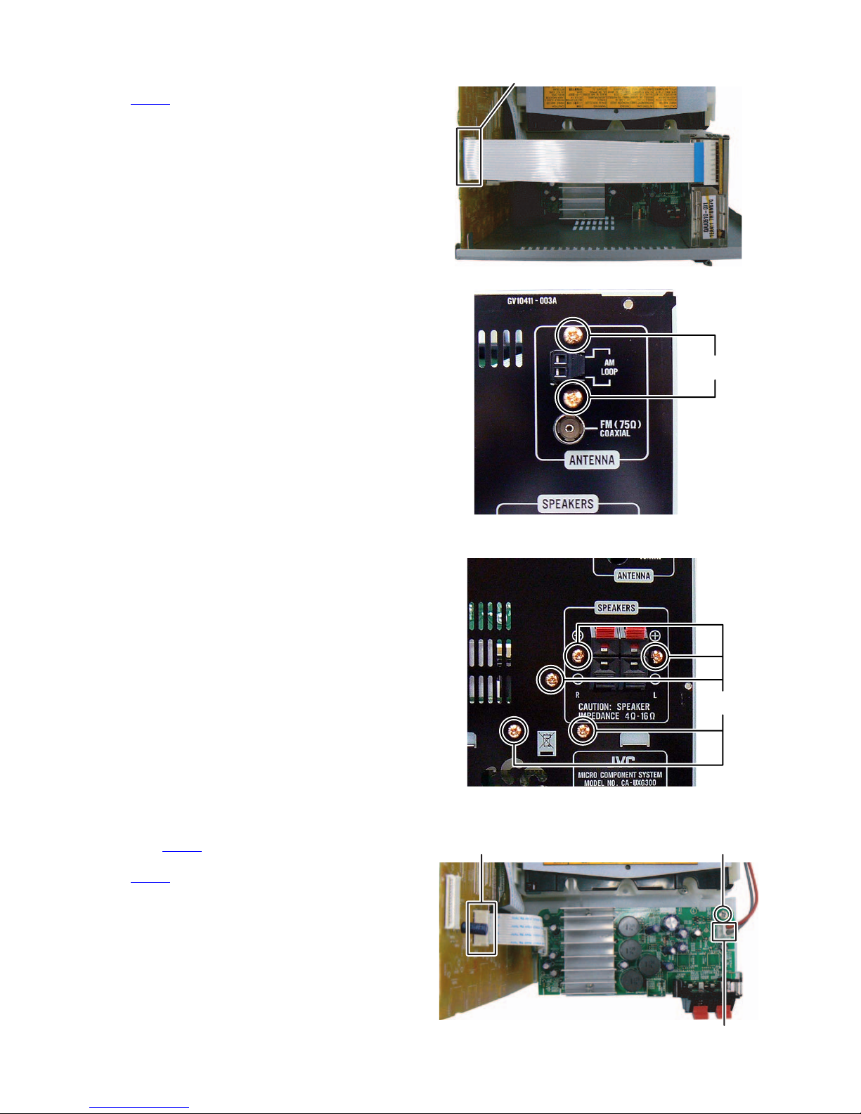
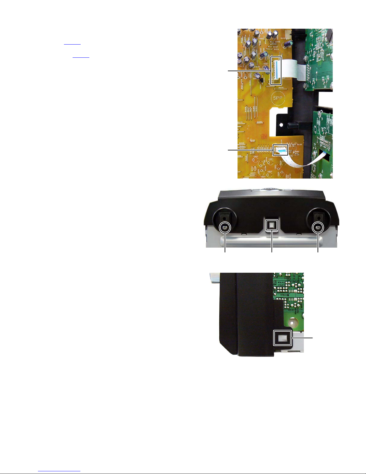
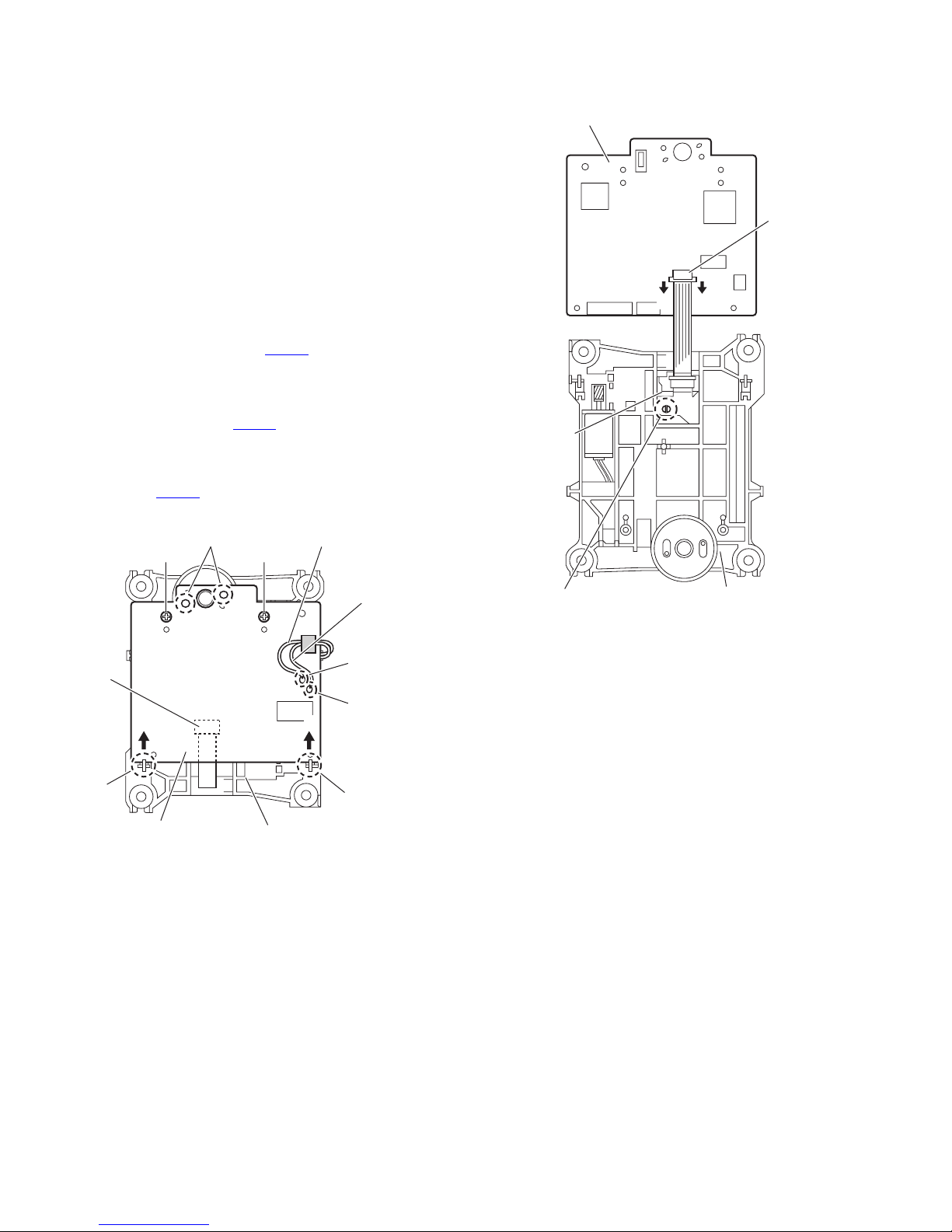
3.1.2 Removing the Tuner pack (See Fig.3, 4)
(1) Disconnect the card wire from Tuner pack connected to
connector CN306
(2) Remove the two screws C attaching the Tuner pack. (See
Fig.4)
of the Micom board. (See Fig.3)
CN306
Fig.3
C
3.1.3 Removing the Rear panel (See Fig.5)
(1) Remove the five screws D attaching the Rear panel.
3.1.4 Removing the Amp board (See Fig.6)
(1) Disconnect the connector wire from Power board connect-
ed to connector CN640
(2) Disconnect the card wire from Amp board connected to
connector CN520 of the Micom board.
(3) Remove the one screw E attaching the Amp board.
of the Amp board.
CN520
Fig.4
D
Fig.5
E
1-8 (No.MB665<Rev.004>)
CN640
Fig.6
Page 9
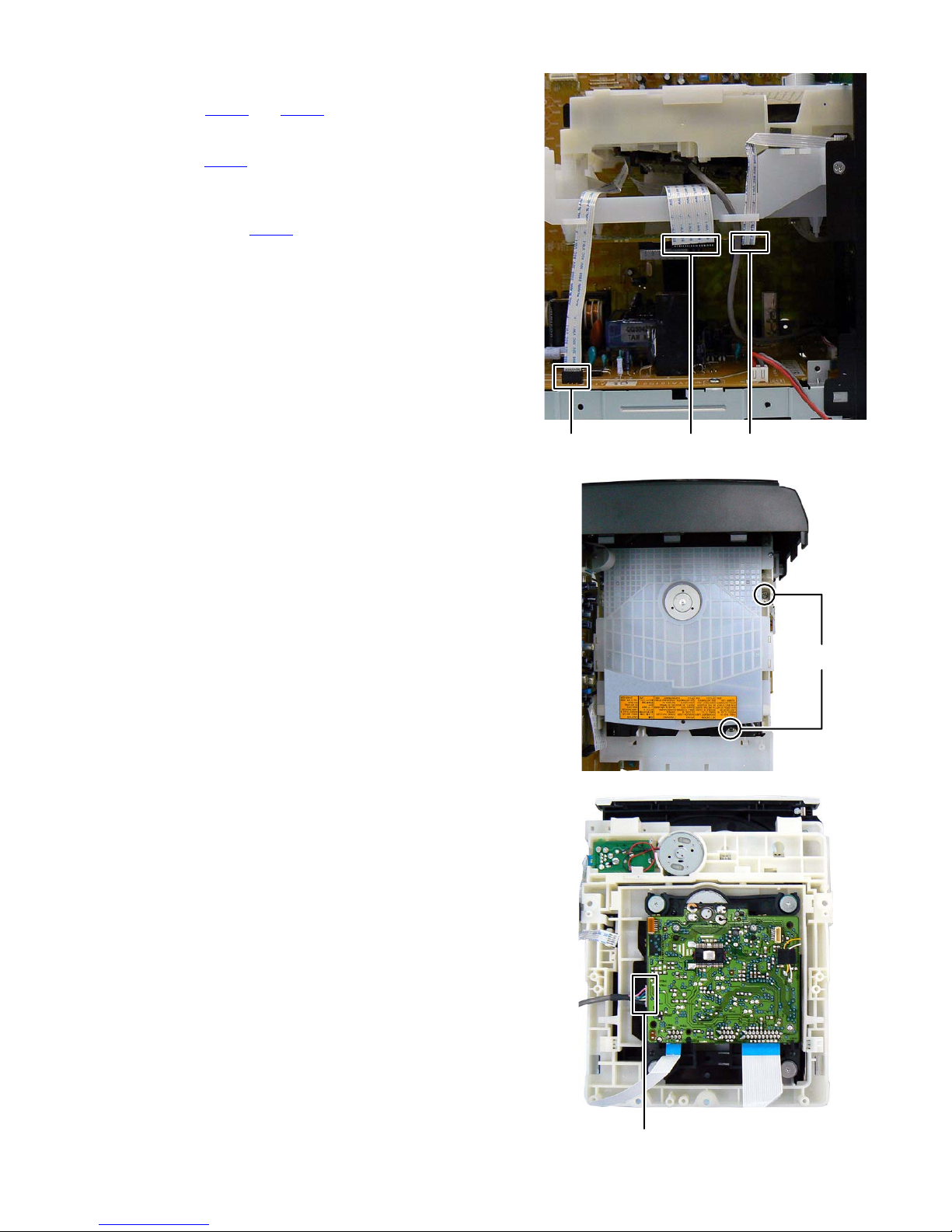
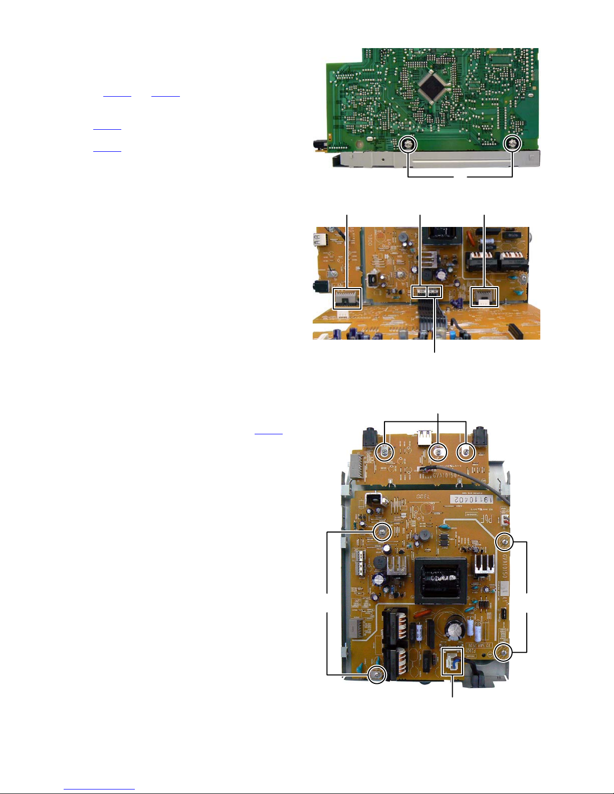
3.1.5 Removing the CD mechanism (See Fig.7 to 9)
(1) Disconnect the card wire from CD mechanism connected
to connector CN360
(See Fig.7)
(2) Disconnect the card wire from CD mechanism connected
to connector CN205
(3) Remove the two screws F attaching the CD mechanism.
(See Fig.8)
(4) Disconnect the connector wire from USB jack board con-
nected to connector CN802
(See Fig.9)
and CN362 of the Connection board.
of the Power board. (See Fig.7)
of the CD servo control board.
CN360CN362CN205
Fig.7
Fig.8
F
CN802
Fig.9
(No.MB665<Rev.004>)1-9
Page 10
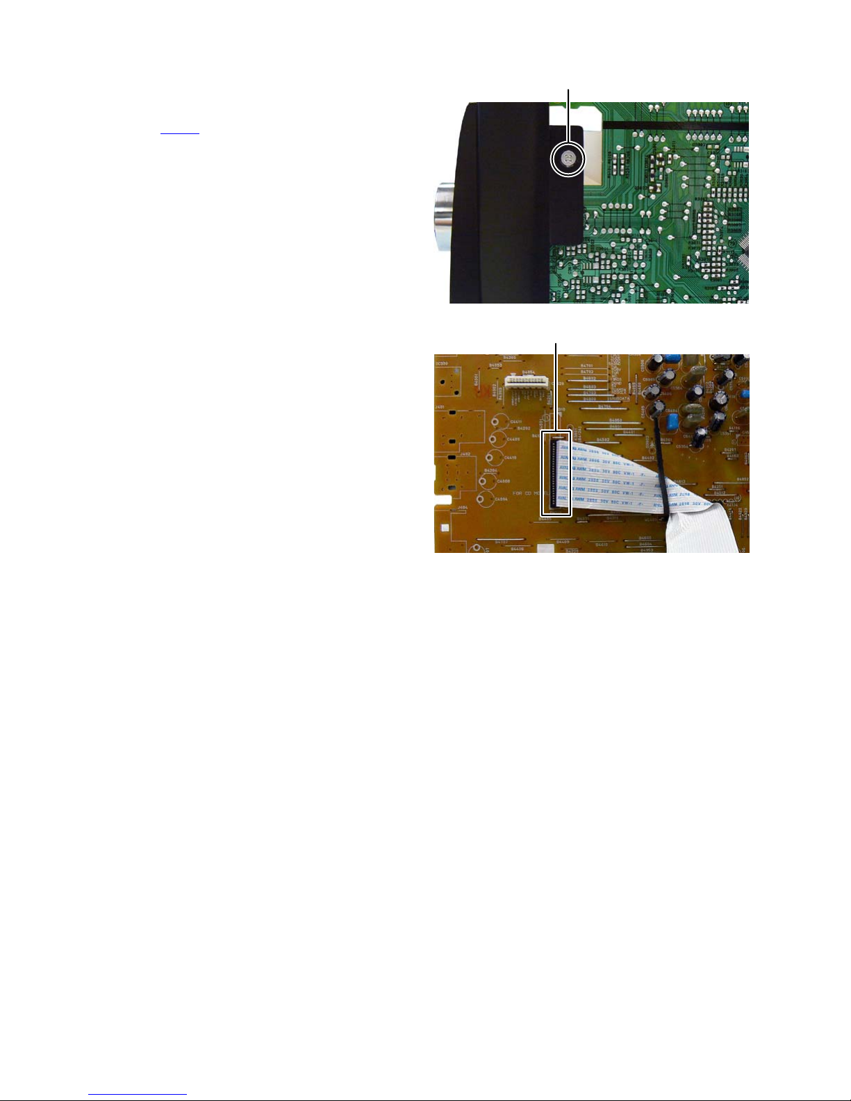
3.1.6 Removing the Mecha chassis (See Fig.10, 11)
(1) Remove the two screws G attaching the both side of the
Front panel. (See Fig.10)
(2) Disconnect the card wire from Connection board connect-
ed to connector CN311
of the Micom board. (See Fig.11)
G
Fig.10
CN311
Fig.11
1-10 (No.MB665<Rev.004>)
Page 11
3.1.7 Removing the Front panel (See Fig.12 to 14)
(1) Disconnect the card wire from FL board connected to con-
nector CN304
(2) Disconnect the card wire from Volume board connected to
connector CN303
(3) Remove the two screws H attaching the Front panel. (See
Fig.13)
(4) Disengage two hooks a engaged both side of the Front
panel. (See Fig.14)
(5) Disengage one hook b engaged bottom side of the Front
panel. (See Fig.13)
of the Micom board. (See Fig.12)
of the Micom board. (see Fig.12)
CN304
CN303
Fig.12
HH
hook b
Fig.13
hook a
Fig.14
(No.MB665<Rev.004>)1-11
Page 12
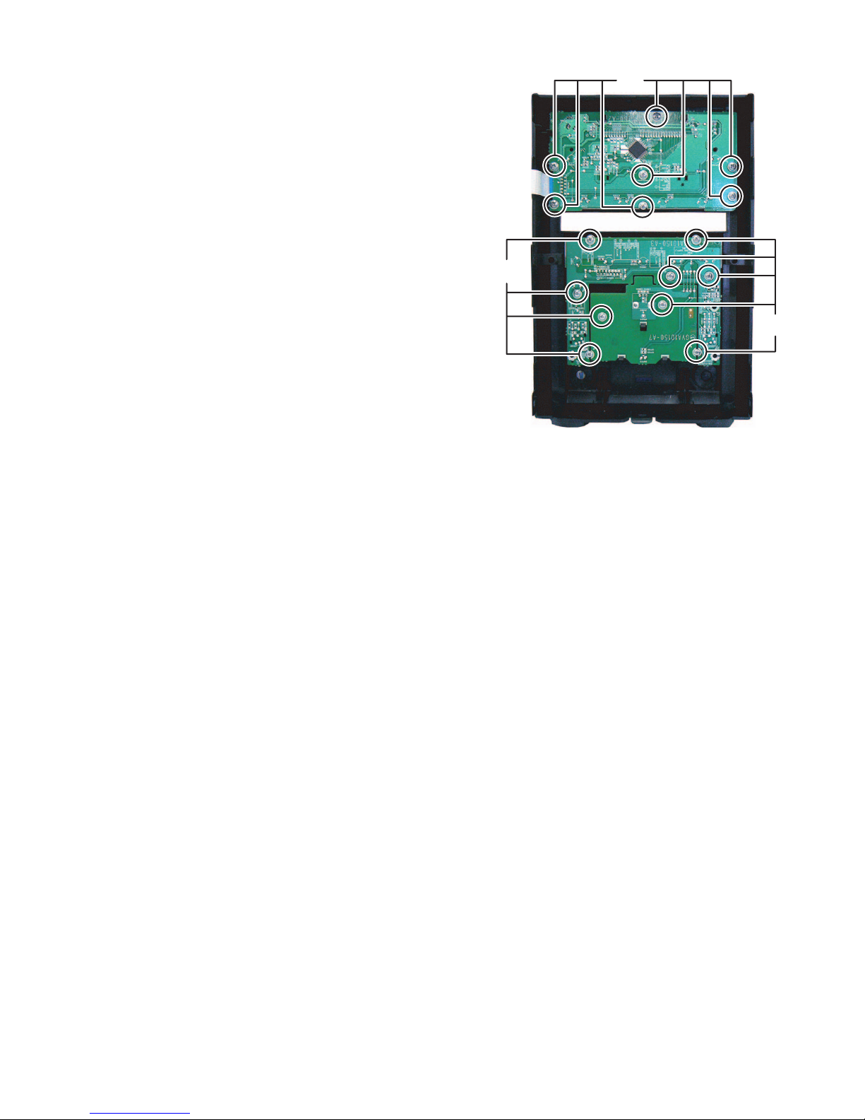
3.1.8 Removing the Micom board (See Fig.15, 16)
(1) Remove the two screws J attaching the Micom board. (See
Fig.15)
(2) Disconnect the flat cable wire from Micom board connected
to connector CN201
Fig.16)
(3) Disconnect the board to board connector connected to
connector CN204
(4) Disconnect the board to board connector connected to
connector CN803 of the USB jack board. (See Fig.16)
and CN203 of the Power board. (See
of the Power board. (See Fig.16)
J
Fig.15
CN204CN803 CN203
3.1.9 Removing the USB jack board (See Fig.17)
(1) Remove the three screws K attaching the USB jack board.
3.1.10 Removing the Power board (See Fig.17)
(1) Disconnect the power cord connected to connector CN200
of the Power board.
(2) Remove the four screws L attaching the Power board.
CN201
Fig.16
K
LL
1-12 (No.MB665<Rev.004>)
CN200
Fig.17
Page 13
3.1.11 Removing the FL board (See Fig.18)
(1) Remove the seven screws M attaching the FL board.
3.1.12 Removing the Volume board (See Fig.18)
(1) Remove the volume knob.
(2) Remove the nine screws N attaching the Volume board.
M
N
N
Fig.18
(No.MB665<Rev.004>)1-13
Page 14
3.2 CD mechanism assembly
• Remove the CD mechanism assembly from main body.
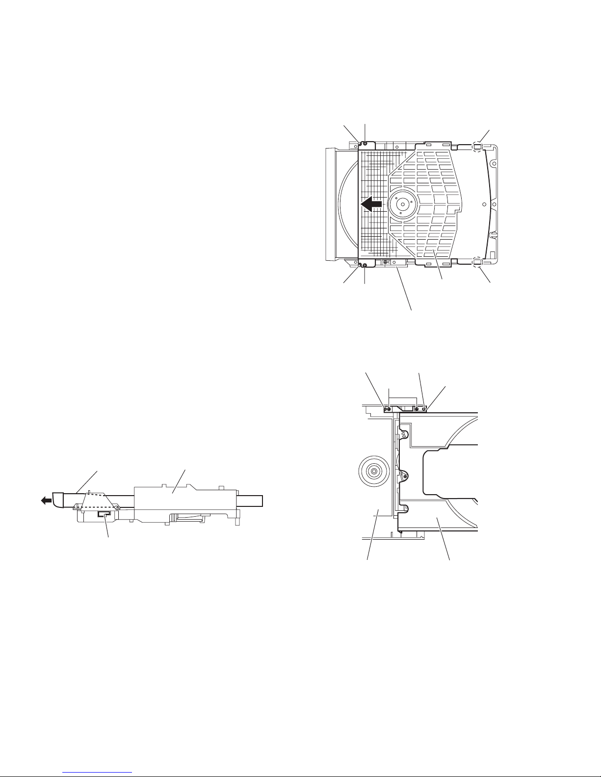
3.2.1 Removing the CD cover
(See Fig.1)
(1) Remove the two screws A attaching the CD cover from bot-
tom side of CD mechanism assembly.
(2) Lift up the CD cover from disengage boss a of the CD
mechanism assembly.
(3) Slide the CD cover to direction of the arrow and remove the
CD cover from fixing part of b.
(4) Remove the CD cover.
Boss a
A
Fixing part b
3.2.2 Removing the tray assembly
(See Fig.2 and 3)
• Remove the CD cover.
(1) Press slide cam and pull out the tray assembly to direction
of the arrow from right side of CD mechanism assembly.
(See Fig.2)
(2) Remove the two screws B attaching the tray assembly
from upper side of CD mechanism. (See Fig.3)
(3) Remove the bussing of the tray assembly from boss c of
the CD mechanism assembly and remove the tray assembly. (See Fig.3)
Tray assembly CD mechanism assembly
Slide cam
Fig.2
Boss a
A
CD mechanism assembly
Fig.1
Boss c
Boss c
B
Fig.3
CD cover
Bussing
Tray assemblyCD mechanism assembly
Fixing part b
1-14 (No.MB665<Rev.004>)
Page 15

3.2.3 Removing the traverse mechanism assembly
(See Fig.4)
(1) Remove the four screws C attaching the traverse mecha-
nism assembly from bottom side of CD mechanism assembly.
(2) Disconnect the card wire from connector CN602
servo board and then take out the traverse mechanism assembly and CD servo board together.
Reference:
When reattaching the traverse mechanism assembly, the card
wire should through the part d.
of the CD
Card wire
d
CD mechanism assembly
CD servo board
C
Traverse mechanism assembly
Fig.4
C
CN602
(No.MB665<Rev.004>)1-15
Page 16
3.2.4 Removing the CD servo board
(See Fig.5 and 6)
• Remove the traverse mechanism assembly.
(1) Remove the two screws D attaching the CD servo board
from bottom side of traverse mechanism assembly. (See
Fig.5)
(2) Remove the solder from solder part e of the CD servo
board. (See Fig.5)
(3) Remove the yellow wire from solder part f of the CD servo
board. (See Fig.5)
(4) Remove the white wire from solder part g of the CD servo
board. (See Fig.5)
(5) Remove the CD servo board to upper side, disengage the
hook c to direction of the arrow 1 then turn over the CD ser-
vo board. (See Fig.5)
(6) Solder to short land part j of pickup. (See Fig.6)
(7) Release the lock of connector CN601
row 2 and disengage the card wire. (See Fig.6)
Caution:
• Solder to short land part j of the pickup then disconnect the
card wire from connector CN601
disconnect the card wire before soldering, pickup is make
sure destroyed by static electricity. (See Fig.6)
• When reattaching the CD servo board, connect the card wire
to connector CN601 and then remove the solder of short
land part j of the pickup.
Solder part e
to direction of the ar-
of the CD servo board. If
Yellow wire
DD
CD servo board
CN601
22
Pickup
CN601
Hook c
White wire
Solder
part f
Solder
part g
1
Traverse mechanism assemblyCD servo board
Fig.5
1
Hook c
Short land part j
Traverse mechanism assembly
Fig.6
1-16 (No.MB665<Rev.004>)
Page 17
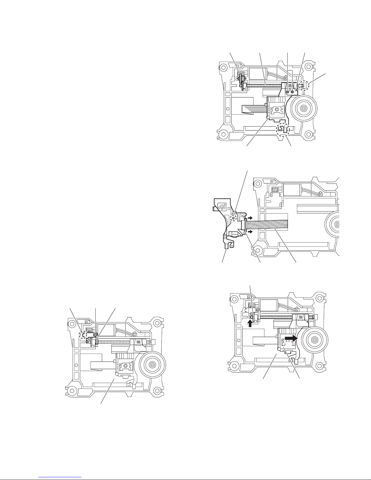
3.2.5 Removing the pickup
(See Fig.7 to 9)
• Remove the traverse mechanism assembly.
(1) Remove the one screw E attaching the plate from upper
side of traverse mechanism assembly. (See Fig.7)
(2) Remove the plate from fixing part k then take out the plate.
(See Fig.7)
(3) Remove the two screws F attaching the LEAD spring and
then take out the LEAD spring. (See Fig.8)
(4) Take out the feed gear, and then remove the shaft of pick-
up from part m of the traverse mechanism assembly. (See
Fig.8)
(5) Remove the pickup from part n of the traverse mechanism
assembly and then take out pickup with shaft. (See Fig.8)
(6) Release the shaft from pickup. (See Fig.8)
(7) Solder the short land part p of the pickup. (See Fig.9)
(8) Release the lock of the connector to direction of the arrow,
and then disconnect the card wire. (See Fig9)
Caution:
• Solder to short land part p of the pickup then disconnect the
card wire from connector. If disconnect the card wire before
soldering, pickup is make sure destroyed by static electricity.
(See Fig.9)
• When reattaching the pickup, connect the card wire to con-
nector and then remove the solder from short land part p.
(See Fig.9)
Feed gear Shaft LEAD spring
Pickup
Short land part
p
F
Part n
Fig.8
Part m
3.2.6 Attaching the pickup
(See Fig.7 to 10)
• Please refer the "Removing the pickup".
(1) Connect the card wire to connector of pickup, and then re-
move the solder from short land part p of the pickup. (See
Fig.9)
(2) Attach the shaft to pickup. (See Fig.8)
(3) Fit the pickup to part n of the traverse mechanism and then
attach the end of the shaft to part k. (See Fig.8)
(4) Attach the LEAD spring and feed gear. (See Fig.8)
(5) Attach the plate. (See Fig. 7)
(6) One turn the LEAD gear to direction of the arrow 1 and fully
shift to direction of the arrow 2. (See Fig.10)
Plate
Fixing part k
E
Pickup Connector Card wire
Fig.9
LEAD gear
1
2
Traverse mechanism assembly
Fig.10
Pickup
Traverse mechanism assembly
Fig.7
(No.MB665<Rev.004>)1-17
Page 18
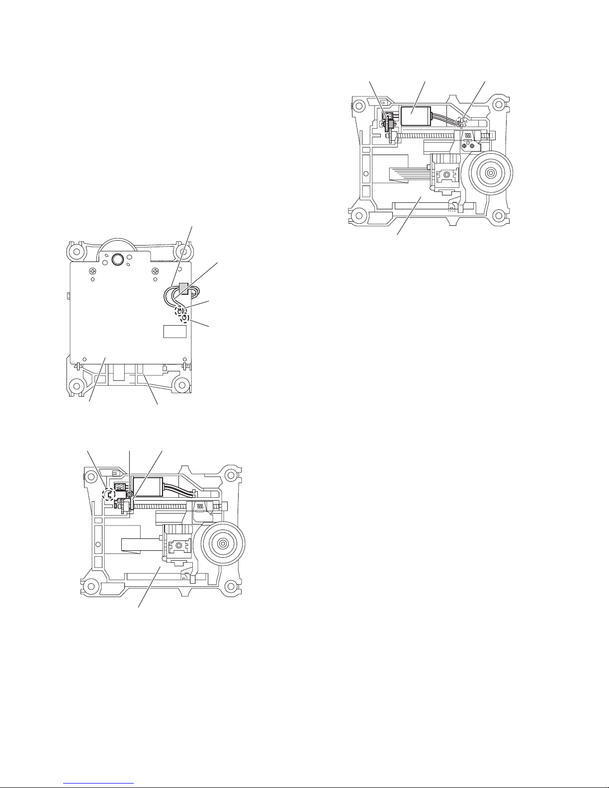
3.2.7 Removing the feed motor
(See Fig.11 to 13)
• Remove the traverse mechanism.
(1) Remove the yellow wire from solder part q of the CD servo
board from upper side of traverse mechanism. (See Fig.11)
(2) Remove the white wire from solder part r of the CD servo
board. (See Fig.11)
(3) Remove the one screw G attaching the plate. (See Fig.12)
(4) Disengage the plate from fixing part s and take out the
plate. (See Fig.12)
(5) Remove the feed gear and take out the feed motor. (See
Fig13)
Reference:
When attaching the feed motor, the wire has to through the
part t of the traverse mechanism assembly. (See Fig.13)
Yellow wire
White wire
Soldered part q
Soldered part r
Feed gear Feed motor
Traverse mechanism assembly
Fig.13
part
t
Fixing part s
Traverse mechanism assembly
G
Traverse mechanism assemblyCD servo board
Fig.11
Plate
Fig.12
1-18 (No.MB665<Rev.004>)
Page 19

3.2.8 Removing the switch board
(See Fig.14)
(1) Disconnect the card wire from CN1
from bottom side of CD mechanism assembly.
(2) Remove the wire from solder part u of the switch board.
(3) Remove the one screw H attaching the switch board to CD
mechanism assembly.
(4) Lift up the switch board by pushing the hook v of CD mech-
anism assembly and take out it from part w.
Reference:
• After attach the switch board to CD mechanism assembly,
wire hooked to part x.
•Hook u of the CD mechanism assembly, it have to bond
lock.
3.2.9 Removing the motor
(See Fig.14 and 15)
• Remove the tray assembly.
(1) Remove the wire from solder part u of the switch board
from bottom side of CD mechanism assembly.
(2) Remove the belt of motor pulley from upper side of CD
mechanism assembly. (See Fig.15)
Caution:
Belt should not apply grease.
(3) Remove the two screws J attaching the motor to CD mech-
anism assembly and take out the motor from bottom side
of CD mechanism assembly. (See Fig.15)
Reference:
After motor attached to CD mechanism assembly, wire should
hook to part w. (See Fog.14)
Switch board Wire
Hook v
of the switch board
CD mechanism assembly
J
Belt
Motor pulley
Fig.15
Solder
part u
Part w
CN1
H
Part x
CD mechanism assembly
Fig.14
(No.MB665<Rev.004>)1-19
Page 20

4.1 Outline
4.2 How to go CD TEST MODE
[STOP] + [CD] + AC in
4.3 Function specification
SECTION 4
ADJUSTMENT
CD TEST MODE
C1 error display
Function
CD TEST MODE
C1 error display
C1 error display
Return to CD TEST MODE
4.4 C1 error history
When 8 key is pressed, syscon send C1 err display command (0x9C 0x01 0x00).
If syscon receive C1 error display status (0xAA 0x01 0x00 ** **), it displays C1 error.
Syscon convert 2byte hex data to decimal data (00000-65635).
4.5 Special mode
[POWER] + [SET] + [REPEAT]: COLD SET
[POWER] + [SET] + [S.TURBO]: FL DISPLAY turn on all segment
[POWER] + [SET] + [BASS/TRE]:Micon version display
press again and again Syscon version
CD version
USB version
Destination
Model name
Key Operation FL display
CD TESTT
>>|
CANCEL
Remocon
Remocon After receive data
Remocon
INITIAL
Er
CD TESTT
*****
1-20 (No.MB665<Rev.004>)
Page 21

SECTION 5
TROUBLESHOOTING
This service manual does not describe TROUBLESHOOTING.
(No.MB665<Rev.004>)1-21
Page 22

Victor Company of Japan, Limited
Audio/Video Systems Division 10-1,1chome,Ohwatari-machi,Maebashi-city,371-8543,Japan
(No.MB665<Rev.004>)
Printed in Japan
VPT
Page 23

SCHEMATIC DIAGRAMS
MICRO COMPONENT SYSTEM
UX-G300B,UX-G300E,UX-G300EN,UX-G300EV
UX-G303E,UX-G303EN,UX-G303EV,UX-G305E
UX-G305EN,UX-G305EV,UX-G300A,UX-G300US
UX-G300UF,UX-G300UT,UX-G300UW,UX-G300UG
UX-G300UN,UX-G305UT
DVD-ROM No.SML2008Q2
CA-UXG300
0
SP-UXG3
Lead free solder used in the board (material : Sn-Ag-Cu, melting point : 219 Centigrade)
Lead free solder used in the board (material : Sn-Cu, melting point : 230 Centigrade)
Contents
Block diagrams
Standard schematic diagrams
Printed circuit boards
0
SP-UXG300
UX-G300EV
UX-G303EV
UX-G305EV
2-1
2-2
2-10 to 12
COPYRIGHT 2008 Victor Company of Japan, Limited.
No.MB665SCH<Rev.004>
2008/9
Page 24

In regard with component parts appearing on the silk-screen printed side (parts side) of the PWB diagrams, the
parts that are printed over with black such as the resistor ( ), diode ( ) and ICP ( ) or identified by the " "
mark nearby are critical for safety.
Page 25

2-1
Block diagram
CN101
CN803
J8000
CN802
W800
CN801
CN205
CN701
CN362
CN306
J6001
CN605
CN520
CN704 CN904
IC201
CD
DRIVER
IC801
USB
CONTROL
IC802,Q801
5V REG.
IC360
MOTOR
DRIVER
IC301
Q301
CPU/CD RF
&
SERVO/DSP
IC600
Q6001
POWER AMP.
D6402,D6601
LEVEL DETECTION
/ AHB CONTROL
S7100 to S7105
KEY MATRIX
IC720
LCD
DRIVER
FL720
LCD DISPLAY
IC700
REMOCON
D7000
STANDBY LED
JS960
ENCODER
CD servo control section
System control section
AUX/HP/USB Jack
LCD,Key switch,LED & Remocon
Key switch & Encoder
Primary & Regulator section
Power amp section
VF1, VF2
VT1, VT2
LD, MD
FM+/-
F+/T+/-
D+/-
HPSW
HPL/R
HPL/R
AUXINL/R
AUXINL/R
USBD+/-
TRAY+/-
TOPEN
TCLOSE
OPENSW, CLOSESW
OPENSW
CLOSESW
TOPEN
TCLOSE
UCS
SCS
SCLK
U2SDT
S2UDT
CPURST
LRMUTE
TU_CE
TU_CK
S2TDT
T2SDT
TUAMSW
RDSCLK
RDSDATA
TUL/R
FLDATA
FLLATCH
FLCLK
FLDATA
FLLATCH
FLCLK
STBYLED
REMOCON
KEY1
KEY1
REMOCON
STBYLED
JOG+/-
GR1 to 10
SG1 to 18
SW601
REST SW
PSW
TRVP, SPOUT
TRP, FOP
MUTE
UCS, SCS, UCLK
U2SDT, S2UDT
NRST, LRMUTE
UCS, SCS, SCLK
U2SDT, S2UDT
CPURST, LRMUTE
CDL, CDR CDL, CDR
CDL, CDR
SCL
SDA
USB_IN
USB_SW
(FDVD5V)
J8300J8100
S9500 to S9504
KEY MATRIX
KEY2
KEY2
JOG+/-
X301
16.9344MHz
IC302
EEPROM
X801
12MHz
USB
HEAD
PHONE
AUX IN
AHB_CTL
LIN
RIN
PROT, DC_DET
MUTE, STBY
AMBEATCUT
LEVEL_DET
PROT
DC_DET
MUTE
STBY
AMBEATCUT
AHB_CTL
LEVEL_DET
VOLCLK
VOLDATA
VOLLATCH
CN364
CN311
Connection section
CN360
CN1
CN312CN304 CN303
TO
SPEAKER
L+/R+/-
TUNER
PAC K
Q3801
RIPPLE FILTER
IC260
US6V REG.
IC211
Q2100,Q2103
SW10V REG.
Q2125 to Q2127
Q2303,Q2131,Q2132
FL SW
A9V
TU9V
Q2304
US3.3V REG.
US3.3V
US3.3V
+18V
SW6V,USB6V
S10V
IC300
MICON
X3001
8MHz
Q3802
SAFETY
REG.
RST
Q3301
RESET
USB5V
USB5V
F+/-
USB6V
USB6V
USB6V
S1
TRAY SWITCH
LOADING MOTOR
Loader
section
M
-VDISP
F+/-
-VDISP
D2151
CN200
CN201 CN203
FW301
T2000
POWER
TRANS.
IC201,IC210, Q2160,Q2161
SW REG.CONTROL
AC IN
D2001
DIODE
BRIDGE
+18V
+18V
+18V
+18V
+18V
S10V
D2131
-VDISP
-VDISP
D2121
F+/-
F+/-
-VDISP
F+/-
CN302
CN204 W2000
CN640
Front panel section
M
M
FEED
MOTOR
SPINDLE
MOTOR
CD
traverse
& pickup
mechanism
IC304
3.3V
REG.
D4V3.3V
SW6V
S10V
+18V
HPSW
SM+/-
USBNPP
STREQ, STIN, STCLK
CS, USBTX, USBRX
USB_IN, USB_NRST
PDOWN
SAFETY1
ECO
FREQCTL
FSW10V
FDVD5V
ECO
PDOWN
FREQCTL
FSW10V
IC500
VOLUME
IC502
Q5301
Q5351
Q5401
AHB
AHB
OUTL
OUTR
HPMUTE
IC503,IC504,IC505
HEADPHONE AMP./MUTE
LOUT
ROUT
Page 26

2-2
Standard schematic diagrams
0V
0V
3.1V
15.3V
0V
0.44V
2.48V
15.2V
271.4V
3.3V
2.7V
OF
ALL INDUCTANCE VALUES ARE IN H(m=mH)
/RATED VOLTAGE (V).
ALL E.CAPACITORS ARE SHOWN IN THE FORM
ALL CAPACITANCE VALUES ARE IN F(P=pF).
IN OHM( ).ALL RESISTANCE VALUES ARE
CAPACITANCE( F)
ALL DIODES ARE MA111-X
VOLT METER
CARBON FILM RESISTOR
MYLAR CAPACITOR.
UNLESS OTHERWISE SPECIFIED.
NOTES
OR
ALL CAPACITORS ARE
1/4W
CERAMIC CAPACITOR
VOLTAGES ARE DC-MEASURED WITH A DIGITAL
3. NI=NO INSERT
2.
4. "0"= SHORT BY PATTERN
1.
CD STOP MODE
ALL RESISTORS ARE
OR OSCILLOSCOPE WITHOUT INPUT SIGNAL.
5%
CONDITION ---
OR 0.063W 5% THICK FILM CHIP RESISTOR
0V
0V
0.6V
18.5V
0V
3.3V
0V
0V
0V
6V
6V
0V
3.1V
0V
3.3V
9.8V
6V
18.5V
6V
0V
0V
0V
-29.3V
-27.1V
-24.2V
18.5V
0V
0.9V
1.2V
0.6V
0.5V
2.7V
11.5V
18.5V
9.9V
0V8.3V 6.0V
-24.2V
3.1V
-24.1V
-24.7V
-24.8V
-24.7V
-24.3V-24.1V
0V
3.1V3.1V
15.7V
3.9V
3.3V
-29.6V
3.1V
-29.6V
-29.2V
-29.6V
-29.1V
3.1V
3.3V0V
11.1V
0V
0V
0V 13V
2.5V
277V
0V
15.3V
0V
1.43V
0.58V
RT1P441C-X
R2
RT1N141C-X
47K
10K
10K
KRA104S-X
47K
10K
R1
R1
RT1P141C-X
R2
R2
KRA102S-X
10K
KRC104S-X
R1
47K
R1
KRC102S-X
R2
RT1N441C-X
47K
& UX-GP5)
(UX-G500V, UX-GP7V)
US UN UG UX UH UJ UT UW
J/C
B E EN EV EE UF UP UY A UB
220/400V
220/200V
100/400V
*
FOR C2008:
*
(UX-G300/303/305
(UX-G500V, UX-GP7V)
FOR DVD MODEL ONLY
SW10V
CD + USB DVD + IPODCD + IPODDVD + USB REC
KIA7806API NINIKIA7806API
NINI
BD9305AFVM-WBD9305AFVM-W
IC212
*
NINIQGF1040C1-05QGF1040C1-07CN205
UX-GP7VUX-GP5/GP9DUX-G500VUX-G300/G800D
IC260
SW6V
FOR DVD MODEL ONLY
*
FOR CD MODEL ONLY
*
US6V
6V
10V
*
QQS0422-001
T2000
GVA10150-A1
US3.3V
17V
ECO
-VDISP
F-
F+
FL SW
!
AC
!
EP201
QNZ0136-001Z
2
EP200
QNZ0136-001Z
!
!
!
!
!
!
!!
!
!
!
!
!
!
!
! !
!
!
sure to use the specified one.
When replacing those parts make
Parts are safety assurance parts.!
NI
B2000
0
R2107
NI
R2117
R2009
NI
C2107
NI
C2117
NI
C2157
NI
C2156
0.1/50
KRC104S-X
Q2127
150
R2125
MA8033-X
D2125
150
R2126
MA111-X
D2126
C2125
0.01/50
KTC3265/Y/-X
Q2126
KTA1505/G/-X
Q2125
NI
B2012
MA8062/M/-X
D2012
KRA102S-X
Q2161
KRC102S-X
Q2160
MA8047/M/-X
D2160
NI
B2118
NI
B2108
MA8075/M/-X
D2011
MA8056/M/-X D2010
0.22/1W
R2108
R2118
0.22/1W
QAD0141-4R0
TH201
VCC
5
GND
6
COMP
7
FB
8
GD
4
ENB
3
CT
2
RT
1
BD9305AFVM-W
IC211
1K
R2106
C2106
470P
18K
R2100
5.1K
R2102
100/16
C2105
20K
R2101
C2103
200P/50
MA22D23-X
D2103
C2102
0.01
NI
C2104
KRC102S-X
Q2100
RSR025P03-X
Q2103
47
QQL28AK-470
L2103
82K
R2104
12K
R2105
B2124
MA8043/M/-X
D2302
R2301
2.4K
MA8039-X
D2301
KTC3203/OY/-T
Q2304
1N4003S-T5
D2600
1N4003S-T5
D2601
FR 1/4W
R2300
100
OUT3GND2IN
1
!
KIA7806API
IC260
100/16
C2601
47/25
C2600
B2110
NI
CP210
CP
NI
D2500
C2110
0.1/50
C2113
220P/50
C2112
0.01
MA22D23-X
D2113
C2116
470P
1K
R2116
18K
R2115
68K
R2114
RSR025P03-X
Q2113
20K
R2111
5.1K
R2112
20K
R2110
KRC102S-X
Q2110
VCC
5
GND
6
COMP
7
FB
8
GD
4
ENB
3
CT
2
RT
1
BD9305AFVM-W
IC212
0.1/50
C2114
47
QQL28AK-470
L2113
100/16
C2115
47/25
C2111
47/25
C2101
C2100
0.1/50
2
KRA104S-X
Q2303
3
NI
B2132
C2019
NI
D2134
MA8024-X
C2121
470/10
R2170
1K
R2015
3.9K
4 1
23
!
PC202
PC123Y22FZ
B2151
NI
B2121
NI
B2001
3
4 1
2
QQR1790-001
LF202
10/50
C2301
NI
K2151
T2.5AH/250V
QMFZ059-2R5-E
F2001
ICP-N10-T
CP211
CP
FR 1/4W
10
R2131
MTZJ11B-T2
D2007
RG1C-LFA1
D2003
C2018
470P/50
NI
C2151
NI
R2151
B2004
R2004
NI
C2011
NI
C2133
0.022/50
2.2K
R2121
NI
R2124
R2134
22k
R2133
3.3K
KTA1504/YG/-X
Q2131
D2132
NI
C2132
NI
D2135
MA8300/M/-X
KRC104S-X
Q2132
C2155
330/25
QQLZ043-120
L2151
C2152
NI
C2131
39/50
D2131
400V/1A
FR104S-A175-T5
D2121
400V/1A
R2165
10K
C2160
0.1/50
R2162
10K
R2163
62K
R2164
2.2K
R2161
2.2K
R2160
1.5K
C2012
10/50
C2020
0.0022/AC250V
FMX-G22S
D2151
200V/10A
C2153
2200/25
MA8220/M/-X
D2008
R2008
12K
D2005
FR104S-A175-T5
400V/1A
C2017
0.001/50
R2007
1.8K
AL01Z-T4
D2006
400V/1A
FR104S-A175-T5
D2004
400V/1A
R2006
68
4 1
23
PC201
PC123Y22FZ
!
R2005
150K/3W
AL01Z-T4
D2009
R2013
1K
C2016
0.01/50
C2015
1/50
R2012
220
R2011 0.39/1W
R2010
0.39/1W
C2013
220P/50
QCZ0136-221Z
C2014
220P/1K
OCP
7
FB
6
SS
5
VCC
4
S
3
NC
2
D
1
!
IC201
STR-W6765N
R2003
220K/3W
R2002
220K/3W
4
3 2
1
LF201
QQR1790-001
C2009
330P/1000
C2001
0.15/AC275V
C2003
100p/AC250V
R2001
3.3M
C2006
NI
C2004
100p/AC250V
NI
VA201
C2007
0.068/AC275V
C2002
NI
100/400
C2008
C2010
0.0047/1000
C2005
NI
RG1C-LFA1
D2002
1342
D2001
KBJ4J
NC7
USB_SW6
DGND5
DGND4
DGND3
USB6V2
USB6V1
QGF1040C1-07
CN205
12
13
11
10
14
15
16
9
6
7
1
2
4
1
2
3
4
QGD2504C1-04Z
CN203
PDOWN6
FDVD5V5
ECO4
FSW10V3
FREQCTL2
US3.3V1
QGB2510K2-06
CN204
DVD5V
1
+18V2
S10V3
SW6V4
AGND5
NI
QGD2504C1-05Z
CN202
MGND1
DGND2
-VDISP3
F-4
F+5
QGD2504C1-05Z
CN201
+18V1
PGND2
QJK015-022202-E
W2000
32
1
KIA431A-T
IC210
21
CN200
QGA7901C1-02
Regulator section
Page 27

2-3
Micom section
FOR DVD MODEL ONLY
FOR UX-GP5/GP7V ONLY
8.9V
9.6V
9.8V
3.3V
3.3V
0V
0V
0V
0V
0V
3.3V
3.3V
3.3V
3.3V
3.3V
0V
0V
0V
0V
3.3V
0V
3.3V
3.3V
0V
0V
0.9V
3.3V
3.8V
3.3V
3.3V0V0V0V0V0V0V0V0V0V0V
3.3V
3.3V
3.3V
0.9V0V0V
3.3V0V0.9V
0V
0V
3.3V
0V0V0V
3.3V
3.3V
3.3V
0V0V0V
1.6V
1.6V
0V0V0V0V0V
2.7V
3.1V0V0.9V
0V
3.3V
0.8V
1.3V
0.9V
0V
3.3V
3.3V
0V
0V
0V
0V
3.3V
0.9V
3.3V
0.9V
0.9V
3.3V
3.1V
3.3V
0.3V
3.3V
3.3V
0V
0.9V
0.9V
0V0V3.1V
3.3V
3.3V
0V
3.3V
0V
0V
0V
0V
3.3V
1.6V
0V
1.6V
0V
0V
3.3V
3.3V
0V
3.3V
0V
3.3V
0V
3.3V
3.3V
3.3V
0V
0V
9.8V
9.8V
6V
6V
0V
0V
0V
0V
0.9V
0.9V
3.3V
4.8V
0V
0V
8.9V
0V
0V
3.8V
3.3V
3.3V
0V
-26.8V
-29.0V
-24.1V
3.3V
3.3V
3.3V
3.1V
3.3V
3.3V0V3.3V
9.8V
3.3V
3.3V
3.3V
0V
0V
0V0V0V0V0V
0V
0.3V
0V
3.3V
3.1V
2.7V0V3.3V
6V
18.5V
9.8V
6V0V0V
0V
-29.3V
-27.1V
-24.2V
* *
*
* *
*
*
*
*
*
*
*
*
*
*
*
6.8K
UX-G300/
U3
3.3K10K
PULL DOWN
NI
NI
DOM
MODEL
30K
IPOD)
UP,UT
UX-GP5
RT1N141C-X
13K
IPOD)
(DVD &
10K
UX-G800D
10K
10K
KRC102S-X
10K
R2
NI
R1
10K
RT1N430C-X
DOM)
10K
4.7K
GP5
R2
&
NI
G303/G305
(DAB
R1
NI
NI
UX-G800D
KRC110S-X
U2
NI
IPOD
*CD MODEL MICON PIN
(UX
U4
NI
J/C DOM
R1(R3198)
VERSION
NI
10K
&
1K
R2(R3098)
USB)
R3090
NI
10K
DETECTION)
* R3070
10K
(NO MODEL
1K
NI
6.8K
1K
1K
30K
1K
NI
R3097
NI
NI
UX-G300/
13K
1K
R3080
UX,UGB,E,EN,EV,
(J/C ONLY)
UW,UY,UJJ,C
10K
R3179
US,UN,UF,
NI
EE
UX-GP5
R3180
3.3K
10K
10K
(CD
R3001
UX-GP7V
R3096
(DAB
NI
NI
10K
R3197
R3079
UT
1K
USB)
UB,A,UP,
R3002
(CD &
NI
UX-G500V
MODEL
R3196
NI
&
R3078
UX-G500V
1K
USB
10K
IPOD)
(CD & USB)
NI
&
NI
(DAB
1K
10K
*PARTS LIST
R2(R3099)
DETECTION)
MODEL
R2(R3092)
USB)(DVD &
E U1
(DVD
UX-GP7V
R1(R3192)
30K13K
(NO MODEL
10K
UX-GP9D
10K
6.8K
PULL DOWN
10K
10K
10K
3.3K
&
USB)
R1(R3199)
JAPAN
10K
(CD &
10K
&
HI POWER)
UX-GP5
10K
&
BLUETOOTH)
G303/G305
10K
FOR UX-GP7V ONLY
Pb
Pr
Py
/ Y
/ Pr
/ Pb
CD + DAB + IPOD
DVD + SCART + IPOD
CD + IPOD
CD + DAB
DVD + SCART
CD
UX-GP9D
UX-GP7V
UX-GP5
UX-G800D
UX-G500V
UX-G300
FOR CD MODEL ONLY
***
OPTICAL OUT
DABR
DABL
For UX-G ONLY
QGF1208C1-05
QGF1208C1-13
For UX-G ONLY
For UX-GP ONLY
1/2VCC
ROM CORRECTION/ERROR HISTORY
GVA10151-A1(1/3)
DABR
DABL
RIPPLE FILTER
ONLYE VERSION
SAFETY REG
TO IPOD DOCK
FLASH MICON
TO DAB UNIT
/RATED VOLTAGE (V).
1/4W
CERAMIC CAPACITOR
VOLTAGES ARE DC-MEASURED WITH A DIGITAL
ALL RESISTORS ARE 5%
CONDITION ---
1.
IN OHM( ).ALL RESISTANCE VALUES ARE
CD STOP MODE
UNLESS OTHERWISE SPECIFIED.
OR
CARBON FILM RESISTOR
MYLAR CAPACITOR.
NOTES
CAPACITANCE( F)
ALL DIODES ARE MA111-X
OR 0.063W 5% THICK FILM CHIP RESISTOR
ALL CAPACITANCE VALUES ARE IN F(P=pF).
ALL E.CAPACITORS ARE SHOWN IN THE FORM
OR OSCILLOSCOPE WITHOUT INPUT SIGNAL.
ALL CAPACITORS ARE
ALL INDUCTANCE VALUES ARE IN H(m=mH).
VOLT METER
2.
3. NI=NO INSERT
OF
4. "0"= SHORT BY PATTERN
DVDPWRON
SAFETY1
AUXINR
DVDPWRON
AGND
DATA
RST
CLK
READY
RST
DATA
CLK
READY
DVDPWRON
IPOD_COUT
TOPEN
OPENSW
TCLOSE
CLOSESW
TUL
TUR
FIPOD
IPDSAFETY
BLANK_CTRL
FSW9V
ECO
DGSENSE
BKLED
REMOCON
FIPOD
LRMUTE
SCS
DVDPWRON
S2UDT
FANON
U2SDT
FANDET
SCLK
CPURST
UCS
CROUT
CBOUT
YGOUT
YOUT
COUT
TX
TOPEN
TCLOSE
UCS
CROUT
CBOUT
YGOUT
YOUT
COUT
VMUTE
VIDEORGB
IPOD_CV
VIDEOSW_C
IPOD_YOUT
IPOD_COUT
BLANK_CTRL
VS3
VS1
VIDEOIP
FTU
TU_CE
HPL
HPR
AUXINL
HPSW
KEY3
SWMUTE
DVDPWRON
IPDSAFETY
STBYLED
CLOSESW
VOLCLK
TCLOSE
SAFETY2
PROT
LRMUTE
LRMUTE
IPOD_TX
DGSENSE
IPOD_RX
FLDATA
FLCLK
FREQ_CTRL
IPOD_CV
TX
RDSDATA
RDSCLK
TUAMSW
FDABANT
S2TDT
TU_CK
T2SDT
FLLATCH
SAFETY1
VOLDATA
LEVEL_DET
JOG+
JOG-
TU_CE
T2SDT
MUTE
DC_DET
SCS
FANDET
OPENSW
VIDEORGB
IPOD_RX
FREQ_BEAT
LEVEL_DET
STBY
MUTE
DC_DET
PROT
IPODL
IPODR
CDL
CDR
TUL
TUR
AUXINL
AUXINR
HPL
HPR
SWMUTE
SMUTE
HPMUTE
VOLLATCH
VOLDATA
VOLCLK
AHB
SCLK
U2SDT
OPENSW
S2UDT
CLOSESW
SCS
CPURST
CDL
CDR
FANON
FANDET
RDSDATA
TUAMSW
TU_CK
FDAB
USBLEDB
S2UDT
KEY3
KEY2
KEY1
VMUTE
IPOD_TX
RDSCLK
HPSW
AHB
USBLEDB
BKLED
DABRST
HPMUTE
VOLLATCH
SMUTE
FDAB
DABRST
FDABANT
FTU
UCS
CPURST
VIDEOSW_C
S2TDT
FANON
STBY
FREQ_BEAT
TOPEN
SCLK
U2SDT
D2SDT
S2DDT
VIDEOIP
IPOD_YOUT
VS1
VS3
SAFETY2
FDAB
FREQ_CTRL
FSW9V
ECO
REMOCON
FLLATCH
FLCLK
FLDATA
STBYLED
KEY1
JOG+
JOG-
KEY2
IPODR
IPODL
S2DDT
D2SDT
DGND
DVDPWRON
VGND
VGND
YOUT
VGND
CBOUT
YGOUT
VGND
COUT
CROUT
+17V
VMUTE
VIDEORGB
DVD5V
IPOD_CV
IPOD_COUT
VIDEOSW_C
VS1
BLANK_CTRL
VIDEOIP
IPOD_YOUT
VS3
AGND
LRMUTE
EP360
QNZ0136-001Z
US3.3V
FREQ_BEAT
LEVEL_DET
STBY
MUTE
DC_DET
PROT
AHB
AGND
SWMUTE
A9V
HPMUTE
VOLCLK
VOLDATA
VOLLATCH
SMUTE
HPR
HPL
AUXINR
AUXINL
TUR
TUL
CDR
CDL
IPODR
IPODL
820
R3952
NI
B4121
NI
C3008
0.001/50
C3715
NI
D3001
0.01/50
C3007
NI
D3002
D3806
NI
R3088
NI
R3086
NI
R3077
NI
R3076
NI
C3714
0.1/16
C3713 0.01/50
K3500
NI
R3046
NI
R3002
R3001
NI
R3752
NI
C3408
NI
R3753
NI
C3409
NI
R3751
NI
C3751
NI
C3755
NI
C3753
NI
R3754
NI
C3752
NIC3754
B4251
NI
C3904
NI
C3804
NI
C3712NIC3711
NI
D3807
R3090
KRC102S-X
Q3802
NI
D3805
UDZW6.8B-X
D3803
UDZW11B-X
D3804
R3007
1K
R3005
1K
R3107
680
R3105
680
R3197
NI
R3350
NI
D3351
NI
R3804
2
R3187
10K
B4108
B4120
B4109
NI
D3902
NC
1
VDD
2
VOUT
3
NC4NC
5
GND
6
CE
7
NC
8
NI
IC380
NIC3852
VSS
3
VDD
2TX1
IC330
NI
R3074
1K
39K
R3611
39KR3711
51K
R3610
51KR3710
NI
R3904
NI
R3803
NI
R3903
R3075
NI
R3123
NI
R3064
1K
R3038
1K
R3192
10K
AD_POWER100
MODEL99
VERSION98
DGSENSE97
KEY396
KEY295
KEY194
LEVEL_DET93
MODEL292
VSS91
FIPOD_CHARGE90
VDD589
IPOD_DATA88
REM87
IPOD_RST86
RDSCLK85
FLCLK84
FLLATCH83
FLDATA82
HPSW81
JOG-80
JOG+79
USBLEDB/IPODLED78
IPOD_CLK77
IPOD_READY76
NTSCRGBSEL
75
CBTEST
74NC73NC72
STBYLED
71
BKLED
70
HPMUTE
69NC68
SAFETY267SAFETY1
66
VOLDATA
65
VOLCLK
64
VSS
63
VOLLATCH
62
AHB
61
EEPDATA
60
EEPCLK
59
SMUTE
58NC57
FDAB
56
DABRST
55
FDABANT
54
TU_CE
53
T2SDT
52
TU_CK
51
S2TDT 50
TUAMSW 49
RDSDATA 48
FTU 47
SWMUTE 46
PRT 45
DC_DET 44
MUTE 43
STBY 42
FREQ_BEAT 41
TOPEN 40
GND 39
TCLOSE 38
VDD18 37
SCLK 36
U2SDT 35
S2UDT 34
SCS 33
D2SDT 32
S2DDT 31
FANDET 30
FANON 29
DVDPWRON 28
CPURST 27
UCS 26
CLOSESW25OPENSW24USB-IN23VIDEOSW_C22VIDEORGB21VIDEOIP20RST19VDD1818VDD17NC16XI15GND14OSC113OSC212MMOD11VMUTE10VS19VS38IPDSAFETY7BLANKCTRL6FSW9V5ECO4FREQ_CTRL3IPODRX2IPODTX
1
MN101EF16KXW
IC300
NI
K3608
0
K3607
0
K3606
0
K3605
NI
K3604
NI
K3603
NI
K3602
0
K3601
0
K3600
R3003
1K
NI
K3609
C3851
NI
R3092
R3166
10K
R3167
NI
R3198
10K
R3097
R3093
1K
R3179
R3180
R3160
NI
R3059NIR30531KR3052
1K
R3145
10K
R3144
10K
R3045
1K
R3125
10K
R3124
10K
A0
1
A1
2
A2
3
GND4SDA
5
SCL
6
WP
7
Vcc
8
IC310
NI
C3005 NI
C3006 NI
NI
D3901
NI
C3902
NI
R3901
NIC3903
NI
C3901
NI
R3902
NI
Q3902
NI
Q3901
QUY158-050Y
B4124
R3021
NI
B4056
NI
Q3702
NI
Q3701
NI
R3701
NI
Q3951
NI
Q3950
NI
R3951
R3199
10K
3
2
1
MC2836-X
D3801
R3049
1K
C3802
100/16
R3801
470
Q3801
KTC3203/OY/-T
C3801
NI
R3702
820
47/6.3
C3701
MA8033/M/-X
D3701
R3011
2.2K
R3196
R3195
10K
R3194
10K
R3181
10K
R3022
NI
R3098
1K
R3095
1K
R3099
1K
R3094
1K
R3096
R3080
R3079
R3081
1K
R3085
1K
R3087
1K
R3078
R3062
1K
R3071
0
R3175
NI
R3067NIR3070
R30661KR30691KR30651KR3060NIR30611KR3058NIR3054NIR3056NIR30511KR3055
NI
R3044
1K
R3040
1K
R3050
1K
R3048
1K
R3043
1K
R3042
1K
R3041
1K
R3047
NI
R3036
1K
R3035
1K
R3034
1K
R3033
1K
R3032
NI
R3031
NI
R3030
NI
R3029
NI
R3027
1K
R3028
NI
R3024
1K
R3023
1K
R3020
NI
C3003
0.1/16
R3010
NI
C3004 0.1/16
R3026
1K
R3025
1K
D3802
NI
NI
C3615
33kR3554
QQL25CK-221Z
NI
L3601
22k
R3552
22k
R3502
NIR3405
33kR3555
NI
C3603
NI
C3407
NI
R3603
0.1/16
C3604
NI
C3455
100p
C3605
33k
R3504
10/50
C3551
NI
C3406
10/50
C3552
100p
C3607
NIC3454
33k
R3505
0.1/50
C3610
NI
C3601
470R3609
NI
C3451
0.001/50
C3606
NI
C3456
10/50
C3501
NIC3611
NI
R3402
NCB31CK-104X
C3100
NIR3608
10k
R3607
NI
R3454
NI
R3452
NIR3404
NIR3403
NI
D3601
100/16
C3613
NI
C3452
NI
C3453
NI
C3402
10/50
C3502
NI
D3602
10k
R3606
100pC3553
NI
C3457
100pC3554
100k
R3501
NI
C3405
NI
C3403
22k
R3503
100pC3505
0.047C3616
NI
C3401
NI
R3401
NI
R3451
22k
R3553
NIC3612
100/16
C3614
100k
R3551
10/50
C3555
10p
C3225
NI
R3453
NIC3404
NI
R3602
NI
C3602
10p
C3503
100p
C3504
10/50
C3506
K3801
NI
C3350
NI
C3001 18P/50
C3002 33P/50
8MHz
X3001
QAX0711-002Z
NI
B4122
NQR0627-002X
K3501
D3301
MA111-X
C3303
0.1/16
RESET
KRC110S-X
Q3301
100/16
C3304
C3301 4.7/50
B4123
R3301
10K
L3001 NI
R3303
1K
R3302
10K
C3302
47/50
RST 15
DATA 14
CLK 13
READY 12
Y 11
C 10
CV 9
OUTR 8
AUDIO_RETURN 7
OUTL 6
DG_SENSE 5
USB_POWER 4
TX 3
RX 2
DGND 1
QGA2001C1-08
CN309
7
5
6
NI
IC370
+
-
4
8
1
3
2
IC370
+
-
JOG+15
JOG-14
KEY213
LED_ILLUMI12
DGND11
USBLEDB10
S9V9
KEY38
AUXINR7
AGND6
AUXINL5
HPSW4
HPL3
AGND2
HPR1
QGF1208C1-13
CN303
TOPEN25
OPENSW24
TCLOSE23
CLOSESW22
DVD5V21
DVD5V20
M9V19
M9V18
MGND17
MGND16
UCS15
CPURST14
SCLK13
FANDET 12
U2SDT11
FANON 10
S2UDT9
NC8
SCS7
LRMUTE6
DGND5
DGND4
CDR3
AGND2
CDL1
QGF1036C1-25
CN311
S10V13
US3.3V12
NC11
DGND10
STBYLED9
FLDATA8
FLLATCH7
FLCLK6
REMOCON5
KEY14
F+3
-VDISP2
F-1
QGF1208C1-13
CN304
LRMUTE31
SCS30
DVDPWR29
S2UDT28
FANON27
U2SDT26
FANDET25
SCLK24
CPURST23
UCS22
MGND21
MGND20
M9V19
M9V18
DVD5V17
DVD5V16
CLOSESW15
TCLOSE14
OPENSW13
TOPEN12
TX11
DGND10
ROUT9
DGND8
BOUT7
DGND6
GOUT5
DGND4
YOUT3
DGND2
COUT1
NI
CN310
HPR1
AGND2
HPL3NC4AUXINL5AGND6
AUXINR7
HPSW8
QGB1214J1-08S
CN312
PDOWN6
FDVD5V5
ECO4
FSW10V3
FREQ_CTRL2
US3.3V1
QGB2510J1-06
CN302
DVD5V10
+18V9
S10V8
SW6V7
AGND6
MGND5
DGND4
-VDISP3
F-2
F+1
QUM159-13DGZ4P1
FW301
4
8
7
5
6
NJM4565E-X
IC350
+
-
1
3
2
+
-
4
8
7
5
6
IC340
+
-
1
3
2
NI
+
-
CLOCK 6
CE 5
DATA 4
VDD 3
RESET 2
VSS 1
QGF1210G1-06
CN308
5V13
DGND12
ANT-PWR11
DABR10
AGND9
DABL8
DGND7
DABTX6
3.3V5
DABRX4
DABON3
DAB-RST2
DGND1
NI
CN305
RDSDATA15
RDSCLK14
TUAMSW13
5V12
DGND11
RDS10
NC9
TU-R8
TU9V7
TU-L6
AGND5
TU-DO4
TU-CK3
TU-DI2
TU-CE1
QGF1208F1-15
CN306
Page 28

2-4
Audio amp section
1.5V
0V0V
1.5V
0V
0V
0V
1.5V
0V
0V0V3.3V
/RATED VOLTAGE (V).
IN OHM( ).ALL RESISTANCE VALUES ARE
CAPACITANCE( F)
ALL DIODES ARE MA111-X
ALL CAPACITANCE VALUES ARE IN F(P=pF).
ALL E.CAPACITORS ARE SHOWN IN THE FORM
ALL INDUCTANCE VALUES ARE IN H(m=mH).
OF
1/4W
CERAMIC CAPACITOR
VOLTAGES ARE DC-MEASURED WITH A DIGITA L
ALL RESISTORS ARE 5%
CONDITION ---
1.
UNLESS OTHERWISE SPECIFIED.
OR
CARBON FILM RESISTO R
MYLAR CAPACITOR.
NOTES
OR 0.063W 5% THICK FILM CHIP RESISTOR
OR OSCILLOSCOPE WITHOUT INPUT SIGNAL.
ALL CAPACITORS ARE
CD STOP MODE
VOLT METER
2.
3. NI=NO INSERT
4. "0"= SHORT BY PATTERN
FOR DVD MODEL ONLY
3.3V
3.3V
0V
0V
0V
3.3V
0V
0V
0V
0V
0V
0.6V 0.6V
0V
0V0V
0V
0V
0.8V 8.9V
4.4V
4.4V
4.4V
0V
8.8V
4.4V
4.4V
4.4V
8.8V
4.6V
4.5V
3.9V
4.6V
4.5V
3.9V
0V
3.9V
3.9V
3.9V
3.9V
3.9V
3.9V
3.9V
3.9V
3.9V
3.9V
3.9V
3.9V
3.9V
8.8V
8.8V
0V
3.9V
3.9V
3.9V
3.9V
3.9V
3.9V
3.9V
3.9V
3.9V
3.9V
3.9V
3.9V0V0V
3.3V
3.3V
GVA10151-A1(2/3)
DABR
DABL
DABR
DABL
DABL
DABR
LR MUTE
AHB
VOLUME IC
SMUTE
S.W.OUT
HEADPHONE AMP
AHB
AUXINL
SMUTE
ROUT
LOUT
SWMUTE
HPL
HPR
HPMUTE
DC_DET
PROT
FR
FL
SWOUTL
LRMUTE
TUR
FR
IPODR
AUXINR
TUL
FL
IPODL
AUXINL
ROUT
LOUT
CDR
CDL
SWOUTR
SWOUTL
CDL
CDR
SWOUTR
FREQ_BEAT
LEVEL_DET
AHB_CTL
STBY
MUTE
ROUT
LOUT
FREQ_BEAT
LEVEL_DET
STBY
MUTE
DC_DET
PROT
AHB_CTL
SMUTE
SWMUTE
IPODL
IPODR
TUL
TUR
AUXINR
VOLLATCH
HPMUTE
VOLCLK
VOLDATA
AHB
OUTL
OUTR
OUTL
VOLDATA
VOLCLK
OUTR
VOLLATCH
LRMUTE
US3.3V
FREQ_BEAT
LEVEL_DET
DC_DET
PROT
STBY
MUTE
SMUTE
SWMUTE
AGND
HPL
HPR
AGND
A9V
CDL
CDR
AUXINR
IPODL
TUR
AUXINL
IPODR
TUL
HPMUTE
AHB
VOLLATCH
VOLDATA
VOLCLK
K5701
B/W
K5702
NI
6 5 4
321
NI
IC509
6 5 4
321
NI
IC506
123
4 5 6
RT3X99M-X
IC505
6 5 4
321
RT3Y97M-X
IC503
6 5 4
321
NI
IC508
+
-
+
-
+
-
+
-
C5506 47/16
3
B4128
B4127
B4126
B4125
24K
R5104
43K
R5105
43K
R5205
24K
R5204
C5509
0.1/16
C5313
NI
C5702
NI
C5306
10/63
C5406
10/63
R5412
NI
R5312
NI
R5313
0
R5413
0
R5902
NI
R5803
NI
R5802
NI
R5801
680
C5802
NI
C5902
NI
C5803
NI
C5801
NI
K5801
B/W
R5901
680
C5901
NI
R5751
NI
Q5701
NI
R5701
NI
C5703
NI
C5706
NI
NI
D5702
C5704
NI
NI
D5701
C5705
NI
R5704
NI
R5703
NI
R5705 NI
NI
C5002
NI
C5601
NI
C5501
NIC5204
AUXINR32IPODR31CDR30TUR29NC28RSELO27RVRIN26RTRE25RBASS124RBASS223RSURR22ROUT21VREF20V+ANA19V+DIGI18VOLLATCH
17
VOLCLK
16
VOLDATA
15
GND14GND
13
LOUT
12
LSURR
11
LBASS210LBASS1
9
LTRE
8
LVRIN
7
LSELO
6NC5
TUL
4
CDL
3
IPODL
2
AUXINL
1
NJU7391V-X
IC500
4 3 2 1
5 6 7 8
NJM4565E-X
IC504
R5505
11K
R5502
10K
R5506
22
C5502
2.2/50
R5602
10K
C5507
22/50
R5507
2.2K
C5604
100P
C5603
150P
R5605
11K
C5505
100/16
R5603
56K
R5503
56K
C5602
2.2/50
R5601
1.2K
R5604
6.8K
C5508
330P
R5607
2.2K
R5504
6.8K
C5504
100P
R5508
10K
C5605
100/16
R5509
10K
D5501
NI
R5501
1.2K
R5606
22
C5608
330P
C5503
150P
18K
R5101
9.1k
R5102
4.7/50
C5105
4.7/50
C5107
3300P
C5106
9.1k
R5202
18k
R5201
4.7/50
C5205
4.7/50
C5207
3300P
C5206
100/16
C5001
10/63
C5212
10/50
C5101
4700P
C5208
0.22
C5210
4700P
C5108
10/50
C5103
4700P
C5211
10/63
C5112
10/50
C5201
0.047
C5109
4.7/50
C5003
4700P
C5111
10/63
C5202
5.6k
R5103
NI
C5104
10/50
C5203
5.6k
R5203
0.047
C5209
0.22
C5110
10/63
C5102
MA111- X
D5351
R5301
1.8K
R5410
1K
R5401
1.8K
R5355
47K
R5307
47K
R5409
470K
R5305
20K
R5310
1K
R5403
1.8K
R5311
10K
R5303
1.8K
C5352
100/16
R5352
270
R5306
2K
R5408
2.4K
R5411
10K
C5353
NI
C5402
0.56
C5354
1/50
C5305
10/63
R5308
2.4K
R5405
20K
R5353
100K
4 3 2 1
5 6 7 8
NJM4565E-X
IC502
C5355
220/10
R5309
470K
R5357
4.7K
R5304
1K
KTC3875/YG/-X
Q5351
C5405
10/63
C5403
0.068
C5304
0.068
R5351
51K
R5354
1.2K
C5404
0.068
C5302
0.56
R5402
NI
KTC3875/YG/-X
Q5301
R5406
2K
R5356
4.7K
R5407
47K
C5351
10/50
C5303
0.068
R5404
1K
KTC3875/YG/-X
Q5401
R5302
NI
R3
R3
R3
R3
R2
R2
R2
R2
R1
R1
R1
R1
Q3
Q3
Q3
Q3
Q2
Q2
Q2
Q2
Q1
Q1
Q1
Q1
AMBEATCUT 1
LEVEL_DET 2
AHB_CTL 3
NC 4
STBY 5
MUTE 6
RIN 7
AGND 8
LIN 9
DC_DET 10
PROT 11
QGF1208C1-11CN520
A9V 1
FAOUTR 2
AGND 3
FAOUTL 4
LRMUTE 5
QGF1036C2-05
CN510
1
2
QNN0780-001
J5001
Page 29

2-5
Digital amp section
*
NIINSERTC6008
INSERT
INSERT
INSERT
NI
NI
NI
NIINSERT
C6217
C6117
C6207
UT ONLY OTHERS
C6107
**
**
*
*
QUY158-050Y
FOR L6301/L6302:
OTHER VERSION
UT/J ONLYQQR0797-002
*
0V
18.5V
0V
0V
2.3V
0V
9.3V
9.3V
9.2V
9.2V
0V
2.5V
0V
0V
3.3V
0V
0V
18.5V
18.5V
18.5V
0V
2.1V
9.3V
9.3V
2.1V
0V
18.5V
18.5V
18.5V
0V0V0V
2.4V
0V
18.5V
9.8V 0V
0V0V0V
0V
0V0V18.5V
18.5V
18.5V
2.2V
9.3V
9.3V0V2.2V
0V
18.5V
18.5V
18.5V
0V0V3.3V
3.3V
2.5V
2.5V
4.9V
0V
0V
0V
0V
3.3V
0V
0V
0V
0V
3.3V
3.3V
KRC110S-X
R2
R1
RT1N430C-X
4.7KR2NI
R1
36dB NINI
32dB OROXNI
R6003
OROX
R6004
20dB
NI26dB
OROXOROX
GVA10152-A1
4."0"= SHORT BY PATTERN
DETECTION
LEVEL
L+
SPKOUT
R+
R+
R-
R-
L+
L-
L-
1/4W
CD STOP MODE
VOLTAGES ARE DC-MEASURED WITH A DIGITA L
NI STANDS FOR NOT INSERTED PARTS.
CERAMIC CAPACITOR
3.
CARBON FILM RESISTORALL RESISTORS ARE
IN OHM( ).
OR OSCILLOSCOPE WITHOUT INPUT SIGNAL.
ALL RESISTANCE VALUES ARE
UNLESS OTHERWISE SPECIFIED.
VOLT METER
CAPACITANCE( F)
5% ALL INDUCTANCE VALUES ARE IN H(m=mH).
ALL CAPACITORS ARE SHOWN IN THE FORM
/RATED VOLTAGE (V).
1.
2.
OR
MYLAR CAPACITOR.
OF
CONDITION ---
ALL CAPACITANCE VALUES ARE IN F(P=pF).
ALL CAPACITORS ARE
NI
PP601
NI
W6000
E409182-001SM
W6001
NI
EP601
NI
C6009
B6312
0
B6311
0
B6303
0
B6304
0
B6313
0
B6314
0
B6302
0
B6301
0
R6604
820
C6612
NI
C6613
0.1/50
R6216
NI
R6215
NI
R6116NIR6115
NI
C6118
NI
C6218
NI
R6114
NI
R6214
NI
C6114
0.47/16
C6104
0.47/16
C6214
0.47/16
C6204
0.47/16
KRC110S-X
Q6001
10/63
C6052
10/63
C6152
NI
C6151
NI
C6051
10K
R6152
10K
R6052
8.2K
R6151
8.2K
R6051
AGND1RIN2MUTEL3CLK4STBY5VSA16VSA17OUTA18OUTA19VDA110SUB11SPIA112HBA113HBB114SPIB115SUB16VDB117OUTB118OUTB119VSB120VSB121NC22ROSC23ROC24VD25DVDD
26
AGND27CPRO
28
GAIN129GAIN2
30NC31
VSB232VSB2
33
OUTB234OUTB2
35
VDB2
36
SUB
37
SPIB2
38
HBB239HBA2
40
SPIA2
41
SUB
42
VDA2
43
OUTA244OUTA2
45
VSA246VSA2
47
PROT
48
OFFSET_DET
49
VREF
50
LIN
51
AVCC
52
R2A15108SP-X
IC600
R60040R6003
NI
470/25
C6001
C6008
R6007
180K
NI
K6004
R6006 39K
R6005
18K
C6006
47/25
0.1/50
C6007
NI
K6000
C6002
47/25
C6003
47/25
0.1/16C6004
C6005
0.33/16
C6210
10/25
C6110
10/25
R6111
330K
C6101
0.47/25
L6111
12
C6105
NI
L6101
12
C6115
NI
R6113
100K
C6112
0.47/16
R6101
330K
C6103
1/16
C6102
0.47/16
C6111
0.47/25
C6113
1/16
R6103
100K
R6112
NI
R6102
NI
C6205
NI
R6202
NI
C6215
NI
R6212
NI
C6213
1/16
R6213
100K
R6211
330K
L6211
12
C6211
0.47/25
C6212
0.47/16
R6203
100K
3
2
1
MC2838-X
D6402
-
R6602
4.7K
3
2
1
D6601
MC2838-X
-
C6611
1/50
R6612
4.7K
C6601
1/50
MA8033-X
D6602
C6602
2.2/50
R6603
51K
R6201
330K
C6412
NI
C6116
NI
C6402
NI
C6109
NI
C6207
C6208
NI
C6217
R6511
12K
L6201
12
R6411
NI
C6411
NI
4
31
6
L6302
C6202
0.47/16
C6117
R6502
NI
R6402
12K
3
2
1
D6403
NI
-
C6201
0.47/25
C6106
NI
C6216
NI
C6512
NI
C6108
NI
C6203
1/16
C6401
10/63
R6512
12K
C6501NIC6511
10/63
C6107
3
2
1
D6401
NI
-
R6401
12K
C6206
NI
C6502
NI
R6412
NI
R6501
NI
4
31
6
L6301
C6209
NI
AMBEATCUT 11
LEVEL_DET 10
AHB_CTL 9
AGND1 8
STBY 7
MUTE 6
RIN 5
AGND1 4
LIN 3
DC_DET 2
PROT 1
QGF1208C1-11
CN605
+18V 1
PGND 2
QGA3901C1-02
CN640
2
1
3
4
5
J6001
QNB0303-001
Page 30

2-6
Front section
-24.2V
-24.2V
-26.5V
-26.5V
-28.5V
-26.1V
-26.1V
-26.1V
-26.1V
-26.1V
-25.8V
-26.1V
-26.1V
-26.1V
-28.7V
-28.7V
-25.8V
-25.8V
-20.5V
-25.8V
-28.5V
-28.4V
-26.2V
-23.1V
-28.4V
-28.4V
-25.8V
-25.8V
-25.8V
-23.1V
-23.1V
-28.4V
0V
0V
3.3V
3.3V
3.3V
0V
0V
0V
0V
0V
0V
0V
0.3V
-26.8V
-29.0V
-24.1V
3.3V
3.3V
3.3V
3.1V
3.3V
3.3V
0V0V3.3V
9.8V
3.3V0V3.3V
-26.1V
-26.1V
-26.1V
-25.8V
-26.1V
-26.1V
-26.1V
-26.1V
-26.1V
3.3V
0V
-26.2V
-28.7V
-28.7V
-29.0V
-28.5V
-28.5V
-25.8V
-25.8V
-20.5V
-28.4V
-25.8V
-28.4V
-28.4V
-25.8V
-28.4V
-25.8V
-25.8V
-23.1V
-23.1V
-23.1V
3.3V
0V
0V
0V
3.3V
3.3V
3.3V
0V
1.9V
0V
0V
0V
0V
E/UP SERIES ONLY
UX-G500V SERIES ONLY
QGF1208F1-07
CN905
QGF1208F1-13
CN903
UX-G300 SERIES ONLY
UX-GP SERIES ONLY
QGF1208F1-05
CN904
FOR UX-GP SERIES
FOR UX-G SERIES
* UX-G500V ONLY
* UX-GP SERIES ONLY
HP
-
+
* UX-G SERIES ONLY
0V
0V
-
5V
0V
GVA10150-A4
+
USB
0V
AUX IN
IPOD BLUE ILLUMINATION
GVA10150-A3
* FOR K9801-K9808
USE NRSA63J-0R0X
GVA10150-A5
GVA10161-A1
GVA10150-A2
* UX-G DVD & UX-GP CD/DVD MODEL ONLY
USB LED DRIVER
* UX-GP SERIES ONLY
* UX-GP SERIES ONLY
SOURCE ILLUMI.
* UX-G SERIES ONLY
VOLUME
ENCODER
VOL-
VOL+
3) AM 9K/10K switch = FF or FR + Standby
2) Tray Lock = Stop + Standby
1) DVD Test Mode = Stop + Play
Double Key Operation:
SOUND TURBO
EJECT
STOP
FF
FR
DIMMER
STANDBY
FM/AM
AUX
USB
DVD/CD
HP
AUX IN
IPOD
SG3/KS3
SG9/KS9
SG8/KS8
LED4
DI-DT
SG21/GR8
SG11/KS11
SG19/GR10
SG17/KS17
NC
OSC
SG5/KS5
OUT
VSS
SG18/KS18
GR4
SG24/GR5
K1
SG16/KS16
DI-CS
K2
SG2/KS2
SG7/KS7
SG6/KS6
VDD
GNDVCC
STANDBY
VEE
GR1
SG15/KS15
GR2
VSS
GR3
SG1/KS1
VDD
SG14/KS14
4.DIGITAL TRANSISTOR
=
47K
LED2
DI-CLK
22K
LED3
SG20/GR9
3.NI MEANS NO INSERT
SG13/KS13
SG23/GR6
SG22/GR7
SG10/KS10
SG12/KD12
LED1
SG4/KS4
VOLTAGES ARE DC-MEASURED WITH A DIGITAL
ALL FERRITE BEADS ARE QQR0621-001Z
CONDITION ---
/RATED VOLTAGE (V).
1.
NOTES
CAPACITANCE( F)
IN OHM( ).ALL RESISTANCE VALUES ARE
MYLAR CAPACITOR.
CERAMIC CAPACITOR
CARBON FILM RESISTO R5%1/4W
DVD STOP MODE
OF
ALL E.CAPACITORS ARE SHOWN IN THE FORM
ALL CAPACITANCE VALUES ARE IN F(P=pF).
ALL RESISTORS ARE
ORALL CAPACITORS ARE
ALL INDUCTANCE VALUES ARE IN H(m=mH).
UNLESS OTHERWISE SPECIFIED.2.
OR OSCILLOSCOPE WITHOUT INPUT SIGNAL.
ALL DIODES ARE MA111-X
OR 0.063W 5% THICK FILM CHIP RESISTOR
VOLT METER
US3.3V
DGND
FLDATA
SG7
-VDISP
OUTR
AUDIO_RETURN
OUTL
DG_DENSE
TX
DGND
USB_POWER
RX
KEY1
SG1
SG2
SG3
SG4
SG5
SG6
SG7
SG8
SG9
SG10
SG11
SG12
SG13
SG14
SG15
SG16
GR1
GR2
GR3
GR4
GR5
GR6
GR7
GR8
GR9
GR10
SG17
SG18
SG17
SG18
REMOCON
FLCLK
FLLATCH
GR3
SG10
SG4
GR6SG6
SG11
SG5
SG3
SG8
SG2
SG9
GR7
SG15
GR9
SG1
GR2
GR5
SG12
SG14
GR4
SG16
GR8
GR1
GR10
SG13
GND
EP801
QNZ0136-001Z
EP800
QNZ0136-001Z
EP810
QNZ0136-001Z
NI
W9000
GND
K8003
NI
K8004
NI
B9059
B9058
C9601
NI
NI
D9600
NI
D9601
NI
B9057
K9600
NQR0022-002X
C9603
0.1/50
JOG+15
JOG-14
KEY213
LED_ILLUMI12
DGND11
LEDB/USBLEDR10
9V9
KEY38
AUXINR7
AGND6
AUXINL5
HPSW4
HPL3
AGND2
HPR1
NI
R9704
560
R9705
NI
R7304
820
R7305
820
R7302
560
R9701
D7200
NI
R7204
NI
R7205
NI
B7205
NI
B7200
KRC102S-X
Q7301
KRC102S-X
Q7300
2.7K
R7301
0.01/50
C9700
100K
R9703
KRC102S-X
Q9701
4.7K
R9700
KRC102S-X
Q9700
2
2
2
K8400
NI
NI
D8001
C8004 10P
C8105
NI
B8104
K8000
NI
R8102
NI
NI
R8201
K8101
NI
NI
B8103
R8104
NI
R8103
NI
R8400
1K
C8102
NI
K8201
NI
NI
D8002
R8200
0
2
3
1
STZC6.8N-X
D8000
B8400
NI
B8001
C8400
0.1/50
C8200
330P/50
C8002
15p/50
B8003
K8001
NQR0627-002X
B8300
B8201
B8401
C8000
15p/50
C8104
0.1/50
B8102
C8201
NI
NI
D8100
K8100
NI
NI
R8101
K8103
NI
K8300
NI
B8202
C8300
0.1/50
B8200
R8202
NI
NI
D8101
R8100
0
K8102
NI
VEE
4 3 2 1
5 6 7
VCC
8
IC810
NI
B8100
C8402
0.01/50
C8106
NI
C8101
NI
B8000
B8101
C8401
0.01/50
K8200
NI
C8001
100P/50
C8202
NI
C8100
330P/50
K8002
NQR0627-002X
K8401
NI
C9701
0.01/50
D9703
SLR-343VC-T
D9702
SELT1E54CM-S
100K
R9702
K9300
NI
K9400
NI
K9201
NI
K9101
NI
K9802
K9803
K9805
K9806
K9807
K9808
K9804
K9801
560K
R9805
51K
R9802
75K
R9804
75K
R9803
51K
R9801
NI
C9802
NI
C9801
C7202
NI
C7200
NI
0.01/50
C7301
D7301
SELT1E54CM-S
100KR7303
0.01/50
C7300
D7300
SELT1E54CM-S
100K
R7300
2 1
QSW0683-001Z
S9505
2 1
QSW0683-001Z
S9506
R9504
2K
R9400
1K
C9401
0.01/50
C7208 NI
C7207 NI
R7203 100
R7202
100
R7201
100
C7203NIC7204
NI
2 1
QSW0683-001Z
S9504
2 1
QSW0683-001Z
S7105
R9503
2K
2 1
QSW0683-001Z
S9501
R9500
11K
R9501
5.6K
2 1
QSW0683-001Z
S9500
R9502
3.3K
2 1
QSW0683-001Z
S9503
2 1
QSW0683-001Z
S9502
R7100
36K
2 1
QSW0683-001Z
S7100
R7104
2K
2 1
QSW0683-001Z
S7102
R7101
11K
R7102
5.6K
2 1
QSW0683-001Z
S7101
R7103
3.3K
2 1
QSW0683-001Z
S7104
2 1
QSW0683-001Z
S7103
C9200
330p/50
NI
D9101
B9100
B9104
C9100
330p/50
C9104
0.1/50
NI
D9100
C9300
0.1/50
C9402
0.01/50
B9200
K9102
NI
B9400
C9400
0.1/50
B9300
K9401
NI
B9401
C7205
NI
R7000
680
C7000
100/6.3
C7201
0.1/50
C7206 NI
KRA101S-X
RT1N44HC-X
4443424140393837363534
3332313029282726252423
2221201918171615141312
11 10 9 8 7 6 5 4 3 2 1
IC720
PT6315
C7209
0.1/16
C9600
0.01/50
C7210
0.022/50
C9602
0.01/50
D7000
SLI-343U8RC-T
F-41F-40P137P2
36
F+1F+210G59G68G77G86G95G104G113G122G131G14P1820P1721P1622P1523P1424P1325P1226P1127P1028P929P830P731P632P533P434P3
35
QLF0194-001
FL720
C7001
NI
R7200 82K
OUTR8
AUDIO_RETURN7
OUTL6
DG_SENSE5
USB_POWER4
TX3
RX2
DGND1
QGA1002F1-08X
CN914
3
2
1
FW970
ILLUMI 3
LEDB_SUPPLY 2
NC 1
QUM023-07Z4Z491
FW970
HPSW8
AUXINR7
AGND6
AUXINL5
A9V4
HPL3
AGND2
HPR1
QGB1214K1-08S
CN803
5V5
D-4
D+3
GND2
GND1
WJP0094-006A-E
W8000
B8002
B8002
65
GND 4
D+ 3
D- 2
5V 1
QNZ0851-001
J8000
5
4
7
3
1
6
2
QNS0188-001
J8100
5
4
7
3
1
6
2
QNS0188-001
J8300
30
29
28
27
26
25
24
23
22
21
20
19
18
17
16
15
14
13
12
11
10
9
8
7
6
5
4
3
2
1
NNZ0186-001
CN912
F- 13
12
F+ 11
10
987
6
STBYLED 5
4
NC 3
2
S10V 1
QGF1208F1-13
CN704
5
4
2 3 1
GP1UE271XKC1
IC700
7
5
6
4
1
3
2
QNS0289-001
J9100
7
5
6
4
1
3
2
QNS0289-001
J9300
54
231
JS960
QSW1060-001
Page 31

2-7
Connection section Loader section
OF
ALL INDUCTANCE VALUES ARE IN H(m=mH)
/RATED VOLTAGE (V).
ALL E.CAPACITORS ARE SHOWN IN THE FORM
ALL CAPACITANCE VALUES ARE IN F(P=pF).
IN OHM( ).ALL RESISTANCE VALUES ARE
CAPACITANCE( F)
ALL DIODES ARE MA111-X
VOLT METER
CARBON FILM RESISTOR
MYLAR CAPACITOR.
UNLESS OTHERWISE SPECIFIED.
NOTES
OR
ALL CAPACITORS ARE
1/4W
CERAMIC CAPACITOR
VOLTAGES ARE DC-MEASURED WITH A DIGITAL
3. NI=NO INSERT
2.
4. "0"= SHORT BY PATTERN
1.
CD STOP MODE
ALL RESISTORS ARE
OR OSCILLOSCOPE WITHOUT INPUT SIGNAL.
5%
CONDITION ---
OR 0.063W 5% THICK FILM CHIP RESISTOR
1.6V
0V
1.6V
0V
0V
3.3V
3.3V
0V
3.3V
0V
3.3V
0V
3.3V
3.3V
3.3V
0V
0V
9.8V
9.8V
6V
6V
0V
0V
0V
0V
0.6V
0.8V
9.8V
9.8V
0V
0V
0.8V
0.8V
0.6V
0V
0V
0V
0V
0.6V
0.6V
3.3V
3.3V
3.3V
3.3V
3.3V
3.3V
9.1V
9.1V
0V
0V
0V
4.5V
4.5V
0V
0V
1.6V
0V
1.6V
3.3V
(UX-G300/303/305 & UX-GP5)
** FOR CD MODEL ONLY
(UX-G500V, UX-GP7V)
** FOR DVD MODEL ONLY
FMU-MJ4-2M - UX-GP5
(UX-G500V & UC-GP7V)
(UX-G500V & UC-GP7V)(UX-G300/303/305 & UC-GP5)
GVA10150-A6
FMU-MB6-71M
FMU-MJ4-1M - UX-G300/303/305
FOR CD MODEL ONLY
FOR DVD MODEL ONLY
FAN DRIVER
MOTOR DRIVER
CDL
CDR
LRMUTE
CLOSESW
TCLOSE
OPENSW
TOPEN
SCS
S2UDT
FANON
U2SDT
FANDET
SCLK
CPURST
UCS
LRMUTE
SCS
DVDPWR
FANDET
FANON
SCLK
UCS
CLOSESW
TOPEN
R_OUT
B_OUT
G_OUT
Y_OUT
CPURST
U2SDT
S2UDT
TCLOSE
OPENSW
TX
C_OUT
CDR
CDL
LRMUTE
CPURST
UCS
SCS
SCLK
S2UDT
U2SDT
R_OUT
B_OUT
G_OUT
Y_OUT
C_OUT
TX
DVDPWR
U2SDT
S2UDT
SCLK
SCS
UCS
CPURST
CLOSESW
OPENSW
TOPEN
TCLOSE
FANON
FANDET
1N4003S-T5
D3658
2A02-M
D3655
B3064
K3652
NI
NI
L3650
NI
Q3651
NI
R3650
NI
Q3650
NI
R3651
K3654 NI
C3657
NI
C3659
NI
K3655
NI
B3060
B3063
NI
C3660
1N4003S-T5
D3657
C3656
NI
C3658
100/16
L3651
1N4003S-T5
B3061
1N4003S-T5
D3656
B3065
K3653
NI
C3653
100/16
C3655
100/16
K3651
NI
1N4003S-T5
D3654
0.1/16
C3651
B3067
0.1/16
C3650
1N4003S-T5
D3653
OUT210P29VCC28VCC17IN26IN15VZ4P13OUT12GND
1
LB1641
IC360
B3062
B3066
K3650
NI
MA8047/M/-X
D3650
C3654
100/16
C3652
100/16
CDL1
AGND2
CDR3
DGND4
DGND5
LRMUTE6
SCS7
NC8
S2UDT9
FANON10
U2SDT11
FANDET12
SCLK13
CPURST14
UCS15
MGND16
MGND17
M9V18
M9V19
DVD5V20
DVD5V21
CLOSESW22
TCLOSE23
OPENSW24
TOPEN25
QGF1040C1-25
CN364
LRMUTE31
SCS30
DVDPWR29
S2UDT28
FANON27
U2SDT26
FANDET25
SCLK24
CPURST23
UCS22
MGND21
MGND20
M9V19
M9V18
DVD5V17
DVD5V16
CLOSESW15
TCLOSE14
OPENSW13
TOPEN12
TX11
DGND10
ROUT9
DGND8
BOUT7
DGND6
GOUT5
DGND4
YOUT3
DGND2
COUT1
QGF1040C1-31
CN363
CDRESET 19
UCS 18
SCS 17
UCLK 16
S2UDT 15
U2SDT 14
M9V 13
M9V 12
MGND 11
MGND 10
NC
9
D4V
8
D4V
7
DGND
6
DGND
5
CDR
4
AGND
3
CDL
2
LRMUTE
1
QGF1040F1-19
CN362
MGND3
FAN-ST2
FAN1
NI
CN365
CPURST 25
UCS 24
SCS 23
SCLK 22
S2UDT 21
U2SDT 20
DVDPWR 19
M9V 18
M5V 17
RX 16
MGND 15
MGND 14
TX(SPDIF) 13
D2V 12
D2V 11
D4V 10
C_OUT 9
S5V 8
Y_OUT 7
VGND 6
Y/G_OUT 5
VGND 4
B-Y/B_OUT 3
VGND 2
R-Y/R_OUT 1
CN361
QGF1040F1-25
CLOSESW 5
OPENSW 4
MGND 3
TRAY- 2
TRAY+ 1
QGF1040F1-05
CN360
MOTORLOADING
LVA10530-01A
CLOSEDET
OPENDET
DGND
LM-
LM+
QAR0197-001
- +
5
4
3
2
1
CN1
QGF1016F3-05
S1
QSW1074-001
Page 32

2-8
CD section
MN66F27971FLASH ROM
MASK ROM
(dummy)
(dummy)
(dummy)
(dummy)
USB CONTROL
FOR MEDIA MICON
FLASH WRIGHTER
FOR USB
DEVICE
FOR SYSTEM
or RIPPING
FOR MD
FOR SYSTEM
FLASH WRIGHTER
FOR MN66F27971
LVA10826-401A
16.9344MHz
5V REG
MOTOR
SPINDLE
+
-
MOTOR
+
FEED
-
OPTIMA-727A
TRA
PICKUP
ASS'YMECHA
A'SSY
CD DRIVER
CPU/CD RF & SERVO/DSP
USB_IN
CDLDCUR
CDINDEX
CDTNO
VF1
VF2
PSW
UCS
CDR
CDL
SPOUT
FOP
NRST
TRPTRP
VF2
CDLDCUR
TRVP
NRST
NRST
UCLK
U2SDT
USB_TX
USB_RX
SCS
S2UDT
CDCOPY
CDEMP
BCLK
SRDATA
LRCK
LRMUTE
CDL
CDR
TX
U2SDT
S2UDT
UCLK
SCS
UCS
CS
USB_NRST
MUTE
LRMUTE
SRDATA
LRCK
BCLK
CDEMP
CDCOPY
CDTNO
CDINDEX
STCLK
STIN
STREQ
TRP
FOP
VT2
VT1
MD
LD
TRVP
SPOUT
TX
USB_IN
USB_NRST
USB_IN
STIN
STCLK
USB_RX
USB_TXCSSTREQ
MUTE
F-
T-
FM+
SM-T+F+
SM+
FM-
SM+
SM-
FM-
FM+
PSW
VF1
VT2
VT1
T-
T+
F+
F-
LD
MD
TP816
TP712
R348 100
C205
0.0012
TP111
R221
1k
C382
NI
NI
D802
TP728
CDMLD64
NC63
VDD162
STIN61
NC60
STCLK59
CDMDATA58
CDSTAT57
CDMCCLK56
CS55
STREQ54
VSS53
NC52
NC51
NC50
VDD549
SDA
48
REQ
47
SCL
46
NC
45
NC
44
NC
43
VDD1
42
NC
41
VSS
40
NC
39
VDD3
38
NC
37
NC
36
NC
35
NC
34
NC
33
NC 32
NC 31
NC 30
NC 29
NC 28
NC 27
NC 26
USBIN 25
P01NC 24
NC 23
NC 22
NC 21
NC 20
OCD_SCL 19
OCD_SDA 18
VPP 17
MMOD1
16
MMOD0
15
NRST
14
VSS
13
OSC0
12
OSC1
11
VDD1/VOUT
10
VDD3
9
CD_NRST
8
AVDD
7
USBD+
6
Vss
5
USBD-
4
USBNPP
3
USBNOC
2
IRO_USB
1
MN103SFB5KWM1
IC801
TP709
DGND
TP703
NRSA02J-0R0X
L801
TP717
R205
15k
C333
47/6.3
Vin
7
Sub
6
Cont5Cn
4
GND
3
NC
2
Vout
1
MM1565AF-X
IC802
R821
0
TP309
GND
29
GND
30
VIN1-A1VIN1+A2VCCP13VO1+4VO1-5VO2+6VO2-7VO3+8VO3-9VO4+10VO4-11VCCP212VIN413VIN4G
14
VIN3
15
VIN3G
16
VIN2
17
VIN2G
18
REG-IN
19
REG-OUT
20
VCC-S
21
VREFIN
22
MUTE
23
VIN-SW
24
S-GND
25
VIN1+B
26
VIN1-B
27
VIN1
28
LA6242H-X
IC201
C314
0.15
TP723
C338
47/6.3
R330 10
100
R360
TP601
TP817
R223
1k
TP304
C211
68p
R301
56k
R323
2.7k
0.1
C803
TP716
R319
0
C329
0.015
UCS128
DVDD2127
IRQ1126
IRQ0125
SCS124
USBRX123
USBTX/TSUBUYAKI122
OCDSEL121
SBT(FLASH_DO)120
SBD(FLASH_DI)119
UCLK118
S2UDT117
U2SDT116
MXSEL115
IOVDD3114
MX2113
MX1112
DVSS2111
X2110
X1109
IOVDD2108
NRST107
SEQMODE106
SRVMONON105
PWMSEL104
CSEL103
TEST102
OUTR101
AVDD1100
AVREF99
AVSS198
OUTL97
VCOF
96
PLLFO
95
PLLF
94
IREF
93
DSLF
92
ARFIN
91
ARFFB
90
ARFOUT
89
ARFDC
88
AVDD2
87
RFIN
86
RFOUT
85
REENV
84
CENV
83
LD
82
PD
81
A
80
C
79
B
78
D
77
F
76
E
75
VREF
74
CTRCRS
73
OSCIN
72
AVSS2
71
PSW
70
FOP
69
SDA
68
TRP
67
SCL
66
NC
65
VPP 64
NC 63
TRVP 62
NC 61
SPOUT 60
REGON 59
DVSS1 58
FVDD 57
DVDD1 56
IOVDD1 55
VSSIC 54
A10 53
A0 52
A1 51
A2 50
A3 49
NRAS 48
NCAS 47
NWE 46
A4 45
A5 44
A6 43
A7 42
A8 41
A9 40
A11 39
SDRCK 38
NC 37
NC 36
NC 35
NC 34
TX 33
STIN
32
STCLK
31
STREQ
30
NC
29
NC
28
NC
27
NC
26
CDINDEX
25
CDTNO
24
CDCOPY
23
CDEMP
22
BCLK
21
LRCK
20
SRDATA
19
NRFDET
18
REGON2
17
REGVDD
16
REGOUT
15
SRAMVDD
14
DVSS3
13
NPWDOWN
12
NPWDOWN_OUT
11
BDO
10
SRVMON0(FE/TBAL)
9
SRVMON1(TE/FBAL)
8
MUTE
7
CS
6
USB_NRST
5
TSUBUYAKI_SW
4
CUR3.3V
3
CDLDCUP
2
LRMUTE
1
MN6627971DA
IC301
R358
1M
R209
5.6k
R336
10
C811
0.1
K706
0
F
0.1
C101
47kR341
ARF
TP311
C807
0.1
TP114
C341
0.1
K705
0
R322
820
C316
0.1
C315
47/6.3
1kR351
TP721
R214
4.7k
TP811
R310
220
470
R381
C218
220/10
R331 10
TP801
TP113
TP719
0
R369
RF
21
QSW1047-002
SW601
NQR0360-002X
K802
12.000MHz
QAX0724-001Z
X801
R311 1k
TP301
TP102
TP722
F
0.1
C102
C207
6800p
TP109
1k
R315
R329
NI
NC
1
NC
2
A2
3
GND4SDA
5
SCL
6
WP
7
Vcc
8
S-24CS16A0I-G-X
IC302
SPO
TP172
NI
C202NIC201
22k
R801
MA2SD31-X
D302
TP303
R312 100
TP101
TP103
0.1
C804
56k
R819
0.1
C806
C219
0.1
RT1N141C-X
Q801
R309
220
C377
0.1
C332 0.022
K701
0
NAX0375-001X
X301
R367
56k
C344
27p
TP824
30P
C801
TP302
R377
10k
470
R382
R333
NI
R207
6.8k
C321
0.1
C310
0.1
R204
27k
C309
0.1
R338 10k
NQR0022-002X
K709
TVP
R208
10k
NI
R384
4.7k
R364
K703
0
R203
1k
R325
47k
C814
2.2
C322 680p
NI
C204
TP115
R211
15k
R324
82k
C816
470p
C334
47/6.3
0
R807
TP707
C342
0.1
20R802
R202
15k
R206
5.6k
TP310
TP104
R308
220
0.1
C702
220/6.3
C815
10k
R350
0.1
C805
C221
0.1
C328
0.1
C326
0.082
0.1
C701
TP171
R102
150
47k
R820
TP714
1kR809
C361
0.1
TP173
C312
0.1
1k
R368
NI
D801
TP306
FOP
NQR0022-002X
K707
C324
0.33
TP108
C301
0.1
4.7k
R363
F
0.1
C103
TP813
NQR0360-002X
K801
TP825
2.2
C305
C809
10
R210
15k
R376
10k
VREF
TP724
C817 1
1kR810
TP718
1k
R814
TP726
R701 1k
R352
10k
TP704
1
C306
R224
0
ISA1530AC1/QR/X
Q301
NQR0022-002X
K708
K702
0
NI
D301
R222
1k
TP174
15kR816
R212
5.6k
C330
4.7
C304
0.1
R313 100
R343
10k
R359
220
C320
0.1
TP725
TRP
TP341
C327
1000p
R320
0
R213
10k
3.3k
R806
TP701
NI
C203
TP823
TP105
1k
R101
C343
27p
R346 100
C319 0.33
R357 10k
27P
C802
C376
0.22
TP822
C339
47/6.3
TP305
R314 100
R356 10k
C381
NI
TP710
C208
2200p
47k
R803
C220
0.1
33kR303
C337
0.1
10k
R383
K704
0
C325
1000p
R321
0
C340
0.1
TP702
TP727
47kR339
TP715
0
R808
C821
NI
R353
10k
R201
68k
150
R805
TP821
56kR304
20
R815
15k
R817
NC
1
VDD
2
Vo
3
NC4NC
5
GND
6
CE
7
NC
8
MM3233DF-X
IC304
TP107
TP705
C331
3300p
C206
1800p
VF2 15
Vcc 14
VT2 13
GND 12
VT1 11
Vc 10
VF1 9
VR 8
MD 7
GND 6
LD 5
F- 4
F+ 3
T+ 2
T- 1
QGF0501F8-15X
CN101
GND6
N.C.5
OCD-SDA4
OCD-SCL3
NRST2
VDD31
NI
CN803
+5V5
USBD-4
USBD+3
DGND2
DGND1
QGA2001F6-05X
CN802
USB6V7
USB6V6
DGND5
DGND4
DGND3
USB_IN2
N.C.1
QGF1036F2-07
CN801
CDINDEX8
CDTNO7
CDCOPY6
LRCK5
CDEMP4
SRDATA3
DGND2
BCLK1
QGF1036F2-08
CN702
GND 6
OCDSEL 5
SDATA 4
SCLK 3
NRST 2
VCC 1
NI
CN301
CDRESET19
UCS18
SCS17
UCLK16
S2UDT15
U2SDT14
M9V13
M9V12
MGND11
MGND10
TX9
D4V8
D4V7
DGND6
DGND5
CDR4
AGND3
CDL2
LRMUTE1
QGF1036F2-19
CN701
Page 33

2-9
CD section (FMU-VK1-1M)
Loader section (FMU-VK1-1M)
REG3.3V
2.UNLESS OTHERWISE SPECIFIED.
RT1N141C-X
TRAYDISCCD THE AND MODEA IN
ALL INDUCTANCE VALUES ARE IN uH
USB DEVICE IS NONE.
STOP
ALL RESISTOR ARE 1/16W 5% METAL GLAZE RESISTOR.
/RATED VOLTAGE (V).ALL E.CAPACITORS ARE SHOWN IN THE FORM OF CAPACITANCE(uF)
ALL CAPACITANCE VALUES ARE IN uF(P=pF).
1.VOLTAGES ARE DC-MEASURED WITH A DIGITAL VOLT METER
CONDITION:
10K
3.DIGI Tr
ALL RESISTANCE VALUES ARE IN OHM( ).
NOTES
10K
A'SSY
(SF-P101VZ)
TRA
PICKUP
ASS'Y
QAL1105-001
MECHA
(DA11VZ)
USB CONTROL
LVA10828-02A
16.9344MHz
5V REG
CD DRIVER
CPU/CD RF & SERVO/DSP
F-
F+
T+
T-
FM-
FM+
SM-
SM+
VT1
VT2
CDR
CDL
LRMUTE
CDINDEX
CDTNO
USB_IN
USB_IN
VT2
D
A
B
C
VT1
LD
MD
C
D
A
B
PSW
UCS
CDR
CDL
SPOUT
FOP
NRST
TRPTRP
TRVP
NRST
NRST
UCLK
U2SDT
USB_TX
USB_RX
SCS
S2UDT
CDCOPY
CDEMP
BCLK
SRDATA
LRCK
TX
U2SDT
S2UDT
UCLK
SCS
UCS
CS
USB_NRST
MUTE
LRMUTE
SRDATA
LRCK
BCLK
CDEMP
CDCOPY
CDTNO
CDINDEX
STCLK
STIN
STREQ
TRP
FOP
MD
LD
TRVP
SPOUT
TX
USB_NRST
USB_IN
STIN
STCLK
USB_RX
USB_TXCSSTREQ
MUTE
F-
T-
FM+
SM-T+F+
SM+
FM-
PSW
NI
R811
NI
C204
NI
C203
NI
C201
NI
C202
NI
K803
NI
K804
C317NIC318
NI
C808
NI
NIR804
R328
0
R329
0
TP115
TP114
TP116
TP109
TP121
R326
0
R327
0
F
0.1
C101
F
0.1
C102
F
0.1
C103
TP126
TP125
TP124
TP123
TP719
TP718
TP728
TP727
NI
R803
NI
R801
R224
0
R321
0
R320
0
VREF
NI
L801
C315
47/6.3
C338
47/6.3
TP722
TP813
TP821
C821
NI
R821
NI
TP817
R325
47k
47kR341
47k
R384
NI
R383
C337
0.1
C382
NI
NI
R807
NI
R808
C381
NI
470
R382
470
R381
R336
10
TP341
NC
1
NC
2
A2
3
GND4SDA
5
SCL
6
WP
7
Vcc
8
S-24CS16A0I-G-X
IC302
NI
X801
NAX0375-001X
X301
DGND
TP825
TP824
TP823
TP822
TP801
TP811
TVP
TP816
TP707
TP705
TP113
TRP
FOP SPO
ARF
RF
TP107
TP106
TP309
TP105
TP104
TP103
TP306
TP122
TP102
TP101
TP305
TP112
TP110
TP304
TP303
TP701
TP302
TP301
TP702
TP703
TP111
TP714
TP715
TP716
TP717
TP721
TP723
TP724
TP725
TP726
TP709
TP712
TP710
TP704
TP310
TP311
56kR304
NI
R815
NIR802
NIR810
NIR809
NI
R806
100
R360
R353
10k
R377
10k
R376
10k
R352
10k
10k
R350
R102
0
NI
R805
NIR351
R348 100
R346 100
R357 10k
1k
R368
R367
56k
R301
NI
33kR303
R356 10k
NIR816
R359
220
R358
1M
R308
NI
R309
NI
R310
NI
R311 NI
R312 NI
R313 NI
R314 NI
NI
R315
4.7k
R364
4.7k
R363
NI
R817
47kR339
1k
R101
R338 10k
R343
10k
R319
0
NI
R820
NI
R814
NI
R819
R201
27k
R202
15k
R322
820
R324
82k
R203
1k
R207
6.8k
R208
10k
R209
5.6k
R205
10k
R204
10k
R206
5.6k
R323
2.7k
R214
4.7k
R212
5.6k
R210
15k
R701 1k
R221
1k
R211
15k
R331 10
R330 10
R222
1k
R333
NI
R223
1k
R213
10k
NI
Q801
ISA1530AC1/QR/X
Q301
NI
K801
NI
K708
K705
0
NI
K802
NI
K709
K706
0
NI
K707
K701
0
K704
0
K703
0
K702
0
UCS128
DVDD2127
IRQ1126
IRQ0125
SCS124
USBRX123
USBTX/TSUBUYAKI122
OCDSEL121
SBT(FLASH_DO)120
SBD(FLASH_DI)119
UCLK118
S2UDT117
U2SDT116
MXSEL115
IOVDD3114
MX2113
MX1112
DVSS2111
X2110
X1109
IOVDD2108
NRST107
SEQMODE106
SRVMONON105
PWMSEL104
CSEL103
TEST102
OUTR101
AVDD1100
AVREF99
AVSS198
OUTL97
VCOF
96
PLLFO
95
PLLF
94
IREF
93
DSLF
92
ARFIN
91
ARFFB
90
ARFOUT
89
ARFDC
88
AVDD2
87
RFIN
86
RFOUT
85
REENV
84
CENV
83
LD
82
PD
81
A
80
C
79
B
78
D
77
F
76
E
75
VREF
74
CTRCRS
73
OSCIN
72
AVSS2
71
PSW
70
FOP
69
SDA
68
TRP
67
SCL
66
NC
65
VPP 64
NC 63
TRVP 62
NC 61
SPOUT 60
REGON 59
DVSS1 58
FVDD 57
DVDD1 56
IOVDD1 55
VSSIC 54
A10 53
A0 52
A1 51
A2 50
A3 49
NRAS 48
NCAS 47
NWE 46
A4 45
A5 44
A6 43
A7 42
A8 41
A9 40
A11 39
SDRCK 38
NC 37
NC 36
NC 35
NC 34
TX 33
STIN
32
STCLK
31
STREQ
30
NC
29
NC
28
NC
27
NC
26
CDINDEX
25
CDTNO
24
CDCOPY
23
CDEMP
22
BCLK
21
LRCK
20
SRDATA
19
NRFDET
18
REGON2
17
REGVDD
16
REGOUT
15
SRAMVDD
14
DVSS3
13
NPWDOWN
12
NPWDOWN_OUT
11
BDO
10
SRVMON0(FE/TBAL)
9
SRVMON1(TE/FBAL)
8
MUTE
7
CS
6
USB_NRST
5
TSUBUYAKI_SW
4
CUR3.3V
3
CDLDCUP
2
LRMUTE
1
MN6627971DB
IC301
CDMLD64
NC63
VDD162
STIN61
NC60
STCLK59
CDMDATA58
CDSTAT57
CDMCCLK56
CS55
STREQ54
VSS53
NC52
NC51
NC50
VDD549
SDA
48
REQ
47
SCL
46
NC
45
NC
44
NC
43
VDD1
42
NC
41
VSS
40
NC
39
VDD3
38
NC
37
NC
36
NC
35
NC
34
NC
33
NC 32
NC 31
NC 30
NC 29
NC 28
NC 27
NC 26
USBIN 25
P01NC 24
NC 23
NC 22
NC 21
NC 20
OCD_SCL 19
OCD_SDA 18
VPP 17
MMOD1
16
MMOD0
15
NRST
14
VSS
13
OSC0
12
OSC1
11
VDD1/VOUT
10
VDD3
9
CD_NRST
8
AVDD
7
USBD+
6
Vss
5
USBD-
4
USBNPP
3
USBNOC
2
IRO_USB
1
NI
IC801
GND
29
GND
30
VIN1-A1VIN1+A2VCCP13VO1+4VO1-5VO2+6VO2-7VO3+8VO3-9VO4+10VO4-11VCCP212VIN413VIN4G
14
VIN3
15
VIN3G
16
VIN2
17
VIN2G
18
REG-IN
19
REG-OUT
20
VCC-S
21
VREFIN
22
MUTE
23
VIN-SW
24
S-GND
25
VIN1+B
26
VIN1-B
27
VIN1
28
LA6242H-X
IC201
NC
1
VDD
2
Vo
3
NC4NC
5
GND
6
CE
7
NC
8
MM3233DF-X
IC304
Vin
7
Sub
6
Cont5Cn
4
GND
3
NC
2
Vout
1
IC802
NI
NI
D801NID802
NI
D301
NI
D302
C218
100/16
C339
47/6.3
C333
47/6.3
C334
47/6.3
NI
C815
C809
NI
NI
C804
NI
C803
C816
NI
C817 NI
C219
0.1
NI
C805
C309
0.1
C312
0.1
NI
C806
C208
2200p
C814
NI
C324
0.33
C325
1000p
C211
68p
C326
0.082
C206
1800p
C327
1000p
C328
0.1
C329
0.015
C207
6800p
C330
4.7
C331
3300p
C332 0.022
C205
0.0015
C322 680p
C321
0.1
C319 0.33
C376
0.22
C314
0.15
C807
NI
C316
0.1
C361
0.1
2.2
C305
1
C306
NI
C801
0.1
C702
0.1
C701
C320
0.1
C344
27p
C343
27p
NI
C802
C811
NI
C340
0.1
C341
0.1
C342
0.1
C301
0.1
C310
0.1
C304
0.1
C377
0.1
C220
0.1
C221
0.1
GND6
N.C.5
OCD-SDA4
OCD-SCL3
NRST2
VDD31
NI
CN803
SW 6
SW 5
FM- 4
FM+ 3
SM- 2
SM+ 1
QGA2001F6-06X
CN102
N.C.7
USB_IN6
DGND5
DGND4
DGND3
USB6V2
USB6V1
NI
CN801
BCLK8
DGND7
SRDATA6
CDEMP5
LRCK4
CDCOPY3
CDTNO2
CDINDEX1
NI
CN702
LRMUTE19
CDL18
AGND17
CDR16
DGND15
DGND14
D4V13
D4V12
TX11
MGND10
MGND9
M8V8
M8V7
U2SDT6
S2UDT5
UCLK4
SCS3
UCS2
CDRESET1
QGF1016F8-19W
CN701
Vc 16
VCC 15
E 14
D 13
A 12
B 11
C 10
F 9
GND 8
LD 7
VR 6
MD 5
F+ 4
T- 3
T+ 2
F- 1
QGF1016F8-16W
CN101
GND
6
OCDSEL
5
SDATA
4
SCLK 3
NRST 2
VCC
1
NI
CN301
+5V5
USBD-4
USBD+3
DGND2
DGND1
NI
CN802
CN362
To Connection section
CN205
To Regulator section
W8000
To Front section
MOTORLOADING
LVA10530-01A
CLOSEDET
OPENDET
DGND
LM-
LM+
QAR0197-001
- +
5
4
3
2
1
CN1
QGF1016F3-05
S1
QSW1074-001
CN360
To Connection section
Page 34

2-10
Power board
Printed circuit boards
Lead free solder used in the board (material : Sn-Ag-Cu, melting point : 219 Centigrade)
Lead free solder used in the board (material : Sn-Cu, melting point : 230 Centigrade)
P1B
18V
18V
+18V
T1B
12
16
9
7
NC
CN205
7
1
PGND
W200
1
1
4
S9V
SW6V
AGND
CN203
AGND
SW6V
S9V
CN202
DVD5V
5
1
FSW10V
FREQCTL
SECONDARY
7
4
1
OUT
IN
GND
PRIMARY
US3.3V
ECO
PDOWN
FDVD5V
1
GVA10150-A1
1
1
1
USB6V
1
USB6V
DGND
DGND
DGND
USBSW
1
CN201
F+
F-
-VDISP
DGND-VGND
MGND
1
5
D2125
R2126
D2126
R2300
Q2304
CN202
CN201
R2112
C2125
Q2126
R2125
C2116
R2116
R2115
R2114
C2115
D2113
Q2113
Q2110
R2110
C2114
IC212
R2118
C2110
C2113
L2113
R2111
C2111
Q2127
C2112
R2102
CN204
B2012
C2106
R2106
R2105
Q2125
D2012
R2104
C2105
K2151
D2103
CN203
Q2103
W2000
Q2100
R2100
C2104
R2170
R2015
IC211
PC202
R2108
Q2161
B2132
C2100
D2500
Q2160
HS201
D2302
EP201
EP200
C2019
FC202
FC201
D2601
C2103
D2600
L2103
R2302
LF202
C2301
D2014
D2013
CP211R2131
D2007
D2003
R2301
D2301
C2018
R2101
C2101
C2601
C2600
C2151
R2151
D2152
R2004
C2011
HS251
T2000
CN205
HS260
D2160
IC260
R2117
R2107
D2011
D2010
TH201
Q2303
K2152
C2133
C2107
R2121
R2124
R2134
R2133
Q2131
C2117
C2157
D2132
C2132
D2135
C2156
Q2132
WC201
C2155
L2151
C2152
IC210
C2131
C2121
D2131
D2121
D2134
C2102
R2165
C2160
R2162
R2163
R2164
R2161 R2160
C2012
C2020
D2151
C2153
D2008
R2008
D2005
C2017
R2007
D2006
D2004
R2006
PC201
R2005
D2009
R2013
C2016
R2009
C2015
R2012
R2011
R2010
C2013
C2014
IC201
R2003
R2002
LF201
C2009
C2001
C2003
R2001
CN200
C2006
C2004
VA201
C2007
C2002
C2008
C2010
C2005
D2002
D2001
P1B
T1B
NC
44
34
33
23
22
12
11
1
41 1
13
1
FL-
-VDISP
FL+
KEY1
REMOCON
FLCLK
FLLATCH
FLDATA
STBYLED
DGND
US3.3V
S9V
CN704
13
1
5
10
GVA10150-A2
R7305
R7304
B7200
CN704
FL720
C7202
C7200
C7301
R7204
D7200
D7301
Q7301
R7303
Q7300
R7302
C7300
R7301
D7300
R7205
R7300
C7208
C7207
R7203
R7202
R7201
C7203
C7204
IC700
S7105
R7100
S7100
R7104
S7102
R7101
R7102
S7101
R7103
S7104S7103
C7205
R7000
C7000
C7201
C7206
IC720
C7209
C7210
D7000
C7001
R7200
P1B
P1B
T1B
T1B
W9000
CN905
CN904
13
1
CN905(G500V)9VKEY2
CN903(UX-GP)9VKEY2
CN904 (G300)
7
5
5
1
JOG+
JOG-
KEY2
LED ILLUMI
DGND
JOG+
JOG-
7
1
5
LEDB/USBLEDR
LED ILLUMI
DGND
1
LED ILLUMI
LEDB/USBLEDR
KEY3
AUXINR
AGND
AUXINL
HPSW
NC
ILLUMI
1
FW970
1
3
LEDB SUPPLY
GVA10150-A3
GVA10150-A7
3
13
10
5
1
HPR
AGND
HPL
DGND
D9601
CN903
C9601
R9701
J9100
J9300
D9703
R9703
Q9701
D9600
Q9700
R9700
R9705
R9704
S9505
S9506
R9504
C9603
R9400
C9401
S9504
R9503
S9501
R9500
R9501
S9500
R9502
S9503
S9502
C9200
D9101
K9201
C9100
K9600
C9104
D9100
C9300
C9402
K9102
K9300
K9101
C9400
K9400
K9401
FW970
C9700
C9600C9602
JS960
P1B
( )
( )
T1B
5
8
1
8
1
( )
HPSW
AUXINR
AGND
AUXINL
A9V
HPL
AGND
HPR
CN803
DGND
DGND
D+D-5V
5
( )
( )
( )
( )
1
GVA10150-A4
K8004
K8003
J8300
B8103
B8102
B8104
B8202
B8001
EP801
CN803
C8004
C8102
C8105
C8101
C8002
D8001
R8101
C8100
R8103
R8100
D8101
K8201
R8104
C8104
K8001
K8401
R8202
C8000
IC810
J8100
D8100
K8000
C8400
C8300
J8000
K8002
R8400
R8201
K8300
EP810
K8400
C8200
K8200
C8106
K8100
R8102
K8103
K8102
D8002
C8402
C8001
C8201
C8401
C8202
R8200
K8101
EP800
W8000
D8000
25
DVD5V
DVD5V
TCLOSE
CLOSESW
OPENSW
TOPEN
TX
DGND
ROUT
DGND
BOUT
DGND
GOUT
DGND
YOUT
DGND
COUT
FANON
S2UDT
DVDPWR
SCS
CPURST
SCLK
FANDET
U2SDT
MGND
MGND
UCS
M9V
M9V
T1B
31
1
AGND
1
LRMUTE
DGND
DGND
CDR
CDL
FAN-ST
MGND
19
1
25
1
GND
OUT1
P1
VZ
IN1
IN2
VCC1
VCC2
OUT2
P2
FAN
3
1
GVA10150-A6
10
1
TRAY-
CLOSESW
TRAY+
MGND
OPENSW
5
1
LRMUTE
CDL
AGND
CDR
DGND
DGND
D4V
MGND
MGND
NC
D4V
M9V
M9V
U2SDT
S2UDT
UCLK
SCS
UCS
CDRESET
CPURST
UCS
SCS
SCLK
S2UDT
U2SDT
DVDPWR
M9V
M5V
TX
D2V
RX
MGND
MGND
D2V
D4V
COUT
S5V
YOUT
VGND
GOUT
VGND
BOUT
VGND
ROUT
CN362
CN363
CN361
D3655
CN364
Q3650
CN360
K3653
CN365
Q3651
R3650
R3651
K3654
C3657
C3659
K3655
C3660
D3657
C3656
C3658
D3658
D3656
K3652
D3659
C3653
C3655
K3651
D3654
C3651
C3650
D3653
IC360
K3650
L3650
D3650
C3654
C3652
P1B
(Power board)
(Connection board)
(Volume board)
(FL board)
(Switch board)
(Front input board)
Page 35

2-11
Micom board
Lead free solder used in the board (material : Sn-Ag-Cu, melting point : 219 Centigrade)
Lead free solder used in the board (material : Sn-Cu, melting point : 230 Centigrade)
Amp board
Lead free solder used in the board (material : Sn-Ag-Cu, melting point : 219 Centigrade)
Lead free solder used in the board (material : Sn-Cu, melting point : 230 Centigrade)
P1B
/STBY
/MUTE
RIN
LIN
AGND
DABL
DGND
DABTX
3.3V
DABRX
DABON
DABRST
DNGD
UCS
MGND
TIB
1
13
AGND
1
15
8
1
CN309
IPOD_RST
IPOD_DATA
IPOD_CLK
IPOD_READY
Y
C
CV
OUTR
AUDIO-RETURN
OUTL
DG-SENSE
USB-POWER
TX
RX
DGND
LEDB
9V
TOPEN
M9V
SCLK
U2SDT
S2UDT
OPENSW
FANON
FANDET
CPURST
MGND
M9V
DVD5V
DVD5V
CLOSESW
TCLOSE
RDSDATA
RDSCLK
TUAMSW
5V
DGND
13
REMOCON
KEY1
F-
TUCE
TUDI
TUCK
TUDO
AGND
TUL
TU9V
TUR
NC
RDS
11
PROT
DC_DET
NC
AHB_CTL
LEVEL_DET
1
AMBEATCUT
100
11
1
SW6V
AGND
MGND
1
FOR CD MODEL
1
DVDPWR
LRMUTE
SCS
DGND
ROUT
BOUT
GOUT
YOUT
COUT
DGND
DGND
DGND
DGND
DGND
TX
DGND
AGND
CDL
CDR
HPR
AGND
HPL
NC
AUXINL
AGND
AUXINR
HPSW
8
FOR DVD MODEL
1
DVD5V
S9V
F+
F-
-VDISP
DGND
10
6
1
CE
CLK
DATA
VDD
RESET
VSS
US3.3V
PDOWN
FDVD5V
ECO
FSW9V
FSW6V
HPL
AGND
HPR
+17V
LED_ILLUMI
JOG+
JOG-
KEY2
DGND
KEY3
AUXINR
AGND
AUXINL
HPSW
10
1
15
1
D5V
DGND
ANT_POWER
DABR
1
5
1
25
26
51
75
76
50
15
1
1
6
1
S9V
D3.3V
BKLED
DGND
STBYLED
FLDATA
FLLATCH
FLCLK
F+
-VDISP
Q3950
Q3952
R3955
R3954
R3953
K5802
R3905
K4003
R3952
K4001
K4005
K4008
K5804
K5803
K5806
K5807
B4014
B4013
B4012
B4011
K4009
K4007
K4004
K4006
D3903
C3008
D4001
D4002
C4010
C4011
K5702
K5701
R4008
R4007
K4002
C4305
IC403
L4500
R5105R5104
R3610
R3611
R5205
R5204
R3804
R3904
R3903
R3710
R3711
R3076
B4003
IC506
IC509
R5701
R5751
IC380
R3077
R3123
C3715
CN305
WC403
R3086
CN520
CN302
FW301
IC503
IC505
B4007
C3852
R3088
C3713
CN309
B4008
R3023
C3409
C3408
R3187
C3754
C3755
C3753
R3753
CN304
R3754
R5401
R3192
D3002
D3001
C3007
R3751
R3752
K3501
R5301
C3714
C3752
C3615
B4009
C3751
IC370
EP360
K3608
R3803
R3007
D3806
EP301
IC402
CN303
B4010
CN310
C3712
C3711
WC401
C4302
WC400
CN311
B4006
B4002
B4004
C4312
Q3802
D3805
D3803 D3804
D3807
C3904
R3075
R3175
CN306
C3804
D3351
R3350
D3902
J401
R4300
R4301
R4302
Q4300
Q4301
Q4303
Q4302
R4203
R4103
R4202
R4102
C4202
C4102
C4107
R4201
R4101
C4201
C4101
C4106
C4105
C4104
C4103
C4100
R4109
R4108
R4107
R4106
R4105
R4104
R4200
R4100
J404
C4009
C4008
R4006
J402
C4410
C4004
R4004
R4005
C4005 C4006
C4007
C4003
C4002
C4001
R4003
R4002
R4001
C4400
C4409
C4411
C4402
R4401
R4400
C4408
C4407
C4406
C4405
C4404
C4307
C4401
IC401
B4005
R4508
R4506
C5004
R4504
R3956
R4502
R4500
C5509
C5313
C5702
C5306
C5406
R5412
R5312
R5313
R5413
IC508
R5902
R5803
R5802
R5801
C5802
C5902
CN510
C5803
C5801
K5801
R5901
C5901
CN312
Q5701
C5703
C5706
D5702
C5704
J5001
D5701
C5705
R5704
R5703
R5705
C5002
C5601
C5501
C5201
IC500
IC504
R5505
R5502
R5506
C5502
R5602
C5507
R5507
C5604
C5603
R5605
C5505
R5603
C5506
R5503
C5602
R5601
R5604
C5508
R5504
C5504
R5508
R5509
D5501
R5501
C5608
C5503
R5101
R5102
C5105
C5107
C5106
R5202
R5201
C5205
C5207
C5206
C5001
C5212
C5104
C5208
C5210
C5108
C5103
C5211
C5112
C5204
C5109
C5003
C5111
C5202
R5103
C5101
C5203
R5203
C5209
C5110
C5102
D5351
R5410
C4306
R5355
R5307
R5409
R5305
R5310
R5403
R5311
R5303
C5352
R5352
R5306
R5408
R5411
C5353
C5402
C5354
C5305
R5308
R5405
R5353
IC502
C5355
R5309
R5357
R5304
Q5351
C5405
C5403
C5304
R5351
R5354
C5404
C5302
R5402
Q5301
R5406
R5356
R5407
C5351
C5303
R5404
Q5401
R5302
R3105 R3107
R3197
K3607
K3606
K3605
K3604
K3602
K3601
K3600
C4403
K3609
C3851
C3610
R3092
R3167
R3166
R3198
R3097
R3093
R3179
R3180
R3160
R3065
R3047
R3053
R3144
R3145
R3046
R3125
R3124
IC310
C3005
C3006
R3002
D3901
C5605
C3902
R3901
C3903
C3901
R3902
Q3902
Q3901
R5607
C4303
R5606
Q3702
Q3701
R3701
Q3951
R3951
R3199
D3801
R3052
CN308
C3802
R3801
Q3801
C3801
R3702
C3701
D3701
R3011
R3196
R3195
R3194
R3181
C4412
R3040
R3098
R3003
R3005
R3095
R3099
R3094
R3096
R3080
R3079
R3081
R3085
R3087
R3078
R3061
R3071
R3060
R3059
R3070
R3067
R3069
R3066
R3074
R3064
R3062
R3058
R3054
R3056
R3051
R3055
R3045
R3041
R3050
R3049
R3044
R3043
R3042
R3048
R3036
R3035
R3034
R3033
R3032
R3031
R3028
R3029
R3027
R3030
R3024
R3038
C3003
R3022
R3021
R3020
R3010
R3001
C3004
R3026
R3025
D3802
R3554
L3601
R3552
R3502
R3405
R3555
C3603
C3407
R3603
C3604
C3455
C3605
R3504
C3551
C3406
C3552
C3607
C3454
R3505
C3601
R3609
C3451
IC350
C3606
K3603
C3456
C3501
C3611
R3402
C3100
R3608
R3607
R3454 R3452
R3404
R3403
D3601
C3613
C3452
C4304
C3453
C3402
C3502
D3602
R3606
C3553
C3457
C3554
R3501
C3405 C3403
R3503
C3505
C3616
C3401
R3401
R3451
IC340
R3553
C3612
C3614
R3551
C3555
C3225
R3453
C3404
R3602
C3602
C3503
C3504
C3506
R3090
K3801
C3350
IC330
C3001
C3002
X3001
B4001
K3500
D3301
C3303
Q3301
C3304
C3301
R3301
L3001
R3303
R3302
C3302
IC300
F1A
+17V
PGND
B
B
A
A
STAMPING GROUP NO.
GVA10152-A1
S1A
L+
L-
R+
R-
1
PROT
DCDET
LIN
AGND
RIN
MUTE
STBY
AGND
AHBCTL
LEV_DET
AMBEAT
1
1
B6314
C6009
R6604
W6001
J6001
MARK
UL
R6216
R6215
R6116
R6115
W6000
PbF
C6118
C6218
R6214
R6114
C6613
EP600
EP601
CN605
C6114
C6104
C6214
C6204
B6313
B6312
Q6001
C6052
C6152
C6151
C6051
R6152
R6052
R6151
R6051
IC600
B6311
R6004
R6003
C6001
C6008
R6007
K6004
R6006
R6005
C6006
C6007
K6000
C6002
C6003
C6004
C6005
C6210
N
C6110
N
CN640
R6111
C6101
L6111
C6105
L6101
C6115
R6113
C6112
R6101
C6103
C6102
C6111
C6113
R6103
R6112
R6102
C6205
R6202
C6215
R6212
C6213
R6213
R6211
L6211
C6211
C6212
R6203
D6402
R6602
D6601
C6611
R6612
C6601
D6602
C6602
R6603
R6201
C6412
C6116
C6402
C6109
C6207
C6208
C6217
R6511
L6201
B6304
R6411
C6411
L6302
B6303
C6202
C6117
R6502
R6402
D6403
C6201
C6106
C6216
C6512
C6108
C6203
C6401
B6302
R6512
C6501
C6612
C6511
C6107
B6301
D6401
R6401
C6206
C6502
R6412
R6501
L6301
C6209
P1A
T1A
R-
R+
L-
L+
1
PROT
DCDET
LIN
AGND
RIN
MUTE
STBY
AGND
AHBCTL
LEV_DET
AMBEAT
1
1
+17V
PGND
W6001
J6001
HEAT PROOF FLUX
W6000
EP600
EP601
CN605
C6052
C6152
C6001
C6006
C6002
C6003
C6210
C6110
CN640
L6111
L6101
L6211
C6611
C6601
C6602
L6201
C6411
L6302
C6401
C6501
C6511
L6301
reverse side
forward side side
Page 36

2-12
CD servo control board
Lead free solder used in the board (material : Sn-Ag-Cu, melting point : 219 Centigrade)
Lead free solder used in the board (material : Sn-Cu, melting point : 230 Centigrade)
Loader board
Lead free solder used in the board (material : Sn-Ag-Cu, melting point : 219 Centigrade)
Lead free solder used in the board (material : Sn-Cu, melting point : 230 Centigrade)
forward side
reverse side
P1A
T1A
+
-
CN1
S1
F1A
S1A
2
33
97
64
1
128
96
32
6
7
65
1
8
7
2
1
MARK
UL
PbF
CN701
L801
R384
R383
C382
R807
R808
C381 R382
R381
IC302
IC302
X801
X301
X301
R224
R803
R701
R304
R801
R810
R809
R806
SW601
R360
R377
R376
R350
R357
R367
R303
R356
R359 R358
R308
R309
R310
R311
R312
R313
R314
R364
R363
R325
R339
R821
R101
R820
R329
C821
R819
R201
R202
R322
R324
R203
R207
R208
R209
R205
R204
R206
R323
R214
R212
R210
R221
R211
R331
R330
R222
R333
R223
R213
Q301
Q301
K705
K707
CN702
K701
K704
K703
K702
IC301
IC301
IC801
IC801
IC304
IC304
IC802
IC802
CN101
CN101
CN801
CN802
CN802
C804
C803
C816
C817
C805
C309
C312
C208
C814
C324
C325
C326
C206
C327
C328
C329
C207
C330
C331
C332
C205
C202
C376C314
C807
C316
C361
C305
C103
C102
C101
C320
C344
C343
C337
C811
C301
C304
C377
C221
P1A
A1
T1A
LVA10826-
7
-
7
8
2
8
1
18
1
19
+
2
1
CN701
TP341
TP115
TP108
TP107
TP105
CN803
CN803
TP303
X801
TP824
TP823
TP821
TP707
TP109
TP305
TP114
R369
TP817
TP816
TP111
TP601
TP304
TP302
TP301
TP701
TP113
TP310
TP702
TP703
TP714
TP715
TP716
TP717
TP721 TP723
TP724
TP725
TP726
TP709
TP712
TP710
TP704
TP171
TP173
TP174
TP172
TP311
R815
R802
SW601
R353
R352
R102
R805
R351
TP813
R348
R346
R368
R301
TP811
R816
R336
R315
TP822
R817
R341
R338
R343
R319
R814
R321
Q801
Q801
K801
K708
K802
K709
K706
CN702
IC201
IC201
D801
D802
D301
D302
CN801
CN301
CN301
R320
C809
C219
C806
C211
C322
C321
C204
C203
C201
C319
C306
C801
C702
C701
C802
C340
C341
C342
C310
C220
CD servo control board
Lead free solder used in the board (material : Sn-Ag-Cu, melting point : 219 Centigrade)
Lead free solder used in the board (material : Sn-Cu, melting point : 230 Centigrade)
Loader board
Lead free solder used in the board (material : Sn-Ag-Cu, melting point : 219 Centigrade)
Lead free solder used in the board (material : Sn-Cu, melting point : 230 Centigrade)
forward side
reverse side
P1A
T1A
+
-
CN1
S1
(FMU-VK1-1M)
(FMU-VK1-1M)
F1A
F
S1A
S
MARK
UL
R804
C808
K803
PbF
R224
L801
C203
C315
C338
C821
R821
C337
R807
R808
R336
IC302
X801
X301
CN102
R810
R809
R806
R353
R377
R376
R352
R805
R348
R346R359R358
R308
R309
R310
R311
R312
R313
R314
R315
R364
R363
R339
R814
R201
R202
R322
R324
R203
R207
R208
R209
R205
R204
R206
R323
R214
R212
R210
R701
R211
R331
R330
R333
Q301
K705
K707
K701
K704
K703
K702
IC301
IC801
IC304
IC802
D302
CN101
CN802
C218
C339
C333
C334
C815
C804C803
C816
C817
C805
C309 C312
C806
C208
C814
C324
C325
C326
C206
C327
C328
C329
C207
C330
C331
C332
C205
C204
C202
C314
C807
C316
C361
C305
C306
C103
C801
C102
C344
C343
C802
C811
C340
C301
C377
C220
CN801
CN702
CN701
R811
P1A
T1A
LVA10828
-A1
C317
TP116
TP115
TP114
TP113
TP126
R326
K804
R327
TP719
TP718
TP728
TP727
R803
R801
R383
R321
R320
VREF
TP722
TP813
TP821
TP817
R325
R341
R384
C382C381
R382
R381
TP341
DGND
TP825
TP824
TP823
TP822
TP801
TP811
TVP
TP816
TP707
TP705
TP112
TRP
FOP
SPO
ARF
RF
TP111
TP110
TP309
TP109
R328
TP107
TP306
TP125
TP106
TP105
TP104
TP305
TP103
TP102
TP304
TP303
TP701
TP302
TP301
TP702
TP703
TP101
TP714
TP715
TP716
TP717
TP721
TP723
TP724
TP725
TP726
TP709
TP712
TP710
TP704
TP124
TP123
TP122
TP121
TP310
TP311
R304
R815
R802
R360
R350
R102
R351
R357
R368
R367
R301
R303
R356
R816
R817
R101
R338
R343
R319
R820
R329
R819
R221
R222
R223
R213
Q801
K801
K708
K802
K709
K706
IC201
D801
D802
D301
CN301
C809
C219
C211
C322
C321
C201
C319
C376
C101
C702
C701
C320
C341
C342
C310
C304
C221
CN803
C318
Page 37

< MEMO >
Page 38

Victor Company of Japan, Limited
Audio/Video Systems Division 10-1,1chome,Ohwatari-machi,Maebashi-city,371-8543,Japan
(No.MB665SCH<Rev.004>)
Printed in Japan
VPT
Page 39

PARTS LIST
UX-G300B,UX-G300E, UX-G300EN,UX-G300EV
UX-G303E,UX-G303EN,UX-G303EV,UX-G305E
UX-G305EN,UX-G305EV,UX-G300A,UX-G300US
UX-G300UF,UX-G300UT,UX-G300UW,UX-G300UG
UX-G300UN,UX-G305UT
* All printed circuit boards and its assemblies are not available as service parts.
- Contents -
Exploded view of general assembly and parts list (Block No.M1)
CD mechanism assembly and parts list (Block No.MB)
CD loading base assembly and parts list (Block No.MD) FLM-J6-2M
CD loading base assembly and parts list (Block No.MW) FMU-VK1-1M
Electrical parts list (Block No.01~05 )
Packing materials and accessories parts list (Block No.M3)
MB665PAR<Rev.004>
FMU-MJ4-1M
3- 2
3- 6
3- 8
3-10
3-12
3-20
3-1
Page 40

Exploded view of general assembly and parts list
P
2
P
Block No.
M MM1
20
5
1
10
10
20
Q
P
4
4
38
6
38
C
44
43
D
FL board
7
7
7
7
8
K
8
8
12
16
J
46
O
18
12
R
M
50
47
8
8
Switch board
8
8
25
25
L
52
Front View
Power board
54
24
53
2
J
C
F
A
25
9
K
M
B
40
48
G
H
K
49
3
42
D
41
17
Main board
A
19
27
27
26
3-2
Page 41

MM
36
46
O
18
12
Only G300UF,G300UT,G305UT ver.
J
50
37
M
39
R
50
wer board
54
A
25
K
N
37
47
K
M
N
58
39
E
37
37
57
47
Q
R
11
22
25
L
52
P
13
45
F
L
30
37
25
14
G
AMP board
Connection
board
21
31
32
34
33
35
M
51
B
25
14
O
N
9
B
H
15
29
19
23
27
27
28
28
Only UX-G300B
E
Only UF ver.
Only UT ver.
The parts without symbol number are not service.
59
56
55
3-3
Page 42

General Assembly
Symbol No. Part No. Part Name Description Local
Block No. [M][1][M][M]
1 GV10404-007 A FRONT PANEL 300B,300E,3 00EN,300EV,300A,300US,3 00UF,3
1 GV10404-008 A FRONT PANEL 303E,303EN,3 03EV,305E,305EN,305EV,305UT
2 GV20500-001 A FRONT LEN S 300B,300E,3 00EN,300EV,300A,300US,3 00UF,3
2 GV20500-002A FRONT LEN S 303E,303EN ,303EV
2 GV20500-003 A FRONT LENS 305E,305EN ,3 05EV,305UT
3 GV31136-005A USB LENS 300B,300E,3 00EN,300EV,300A,300US,300UF,3
3 GV31136-006A USB LENS 303E,303EN,3 03EV,305E,305EN,305EV,305UT
4 GV40764-001A FOOT SPACER (x2)
5 GV31130-001A F.BUTTON ASSY
6 GV20502-001A BUTTON 300B,300E,300EN,300EV,300A,300US,300UF,3
6 GV20502-002A BUTTON 303E,303EN,303EV,305E,305EN,305EV,305UT
7 QYSDSF2608ZA TA P SC R EW M2.6 x 8mm(x6 )
8 QYSDSF2608ZA TA P SC R EW M2.6 x 8mm(x9 )
9 QYSDSG3008ZA TAP SCREW M3 x 8mm
10 GV30349- 091A SPAC ER (x2)
11 GV10405-001A MECHA HOLDER
12 QYSBSF3010ZA TAP SCREW M3 x 10mm(x2)
13 QYSDSG3008ZA TAP SCREW M3 x 8mm
14 LV44209-001A WASHER SCREW (x3)
15 LV44209-001A WASHER SCREW
16 GV30349- 048A SPAC ER
17 GV30349- 014A SPAC ER
18 GV30349- 092A SPAC ER
19 GV30349- 076A SPAC ER (x2)
20 QYSSSF3010ZA TAP SCREW M3 x 10mm(x2)
21 QYSDSG3008ZA TAP SCREW M3 x 8mm(x2)
22 GV31137-00 1A HEAT SIN K
23 GV10406- 001A BOTTOM CHASSI S
24 QYSDSG3006ZA TAP SCREW M3 x 6mm(x3)
25 QYSDSG3006ZA TAP SCREW M3 x 6mm(x5)
26 QYSDSG3006ZA TAP SCREW M3 x 6mm(x2)
27 GV40764- 001A FOOT SPACER (x 2)
28 QMPN150-200-JC POWER CORD(EK) 2m BLACK 300B
28 QMPK200-200-JD POWER CORD 2m BLACK 300E,300EN,300EV,303E,303EN,303EV ,305E,3
28 QMPG150-244-JC POWER CORD(AST) 2.44m BLACK 300A
28 QMPR480-200-JC POWER CORD(EU) 2m BLACK 300UF
28 QMPR600-200-JD POWER CORD 2m BLACK 300UT,305UT
29 QZW0033-001 STRAIN RELIEF
30 QAU0510-001 TUNER 300B,300E,300EN,300EV,303E,303EN,303EV,3
30 QAU0509-001 TUNER 300A,300US,300UF,300UT,300UW,300UG,300U
31 GV10411-003A REAR PANEL 300B,300E , 300EN
31 GV10411-004A REAR PANEL 300EV
31 GV10411-010A REAR PANEL 303E,303E N
31 GV10411-011A REAR PANEL 303EV
31 GV10411-013A REAR PANEL 305E,305E N
31 GV10411-014A REAR PANEL 305EV
31 GV10411-006A REAR PANEL 300A
31 GV10411-001A REAR PANEL 300US,300UW,300UG,300UN
31 GV10411-008A REAR PANEL 300UF
31 GV10411-007A REAR PANEL 300UT
31 GV10411-033A REAR PANEL 305UT
32 QYSBSGY3008EA TAP SCREW M3 x 8mm(x2)
33 QYSBSGY3008EA TAP SCREW M3 x 8mm
34 QYSBSGY3008EA TAP SCREW M3 x 8mm(x2)
35 QYSBSGY3008EA TAP SCREW M3 x 8mm(x2)
36 GV10407-001A/S/ METAL COVER 300B,300E,300EN,300EV,300A,300US,300UF,3
36 GV10407-002A/S/ METAL COVER 303E,303EN,303EV,305E,305EN,305EV,305UT
37 QYSBSGY3008EA TAP SCREW M3 x 8mm(x6)
38 QYSDSG3008ZA TAP SCREW M3 x 8mm(x2)
39 QYSDSG3008NA TAP SCREW M3 x 8mm(x2)
40 GV31134-006A TRAY FITTING 300B,30 0E , 300EN,300EV
40 GV31134-008A TRAY FITTING 303E,303EN,303EV,305E,305EN,305EV
40 GV31134-007A TRAY FITTING 300A,30 0U S,300UF,300UT, 300UW,300UG,300U
40 GV31134-009A TRAY FITTING 305UT
41 GV40613- 002A SPACER
42 GV31135-002A VOL KNOB
00UT,300UW,300UG,300UN
00UT,300UW,300UG,300UN
00UT,300UW,300UG,300UN
00UT,300UW,300UG,300UN
05EN,305EV,300US,300UW,300UG,300UN
05E,305EN,305EV
N,305UT
00UT,300UW,300UG,300UN
N
3-4
Page 43

Symbol No. Part No. Part Name Description Local
43 QUQU12- 0508BJ-E FFC WI RE FC 303
44 QUQU12- 1308AJ-E FFC WI RE FC 304
45 QUQU12- 1514AJ-E FFC WIRE FC 306 300B,300E,300EN,300EV,303E,303EN,30 3EV,3
45 QUQU12- 1114AJ-E FFC WIRE FC 306 300A,30 0U S,300UF,300UT, 30 0U W,300U G,300U
46 QUR110-0512AJ-E FFC WIRE FC 360
47 QUR110-1918AJ-E FFC WIRE F C 362 3 00B,300E,300EN , 3 00EV,303E,303EN,303EV,3
47 QUR110-1922AJ-E FFC WIRE FC 362 300UF,300UT,305U T
48 QUR110-2520AJ-E FFC WIRE FC 364
49 QUQU12- 1107AJ-E FFC WIRE FC 60 5
50 QUR110-0718AJ-E FFC WIRE F C 205 3 00B,300E,300EN , 3 00EV,303E,303EN,303EV,3
50 QUR110-0716AJ-E FFC WIRE FC 205 300UF,300UT,305U T
51 QMFZ059-2R5-E FUSE F 2001
52 QYSDSG3008ZA TAP SCREW SC 201
53 QYSDSG3008ZA TAP SCREW SC 260
54 QYSDSG3008ZA TAP SCREW SC 251
55 GV30759- 020A UT LABE L 300UT
55 GV30759- 023A UT LABE L 305UT
56 GV31164-006A UF LABEL 300UF
57 GV30349 - 004A SPACER 3 00UF,300UT,305UT
58 GV30349 - 053A SPACER 3 00UF,300UT,305UT
59 GN40099-001A CCC LABEL 300UF
05E,305EN,305EV
N,305UT
05E,305EN,305EV,300A,300US,300UW,300UG,
300UN
05E,305EN,305EV,300A,300US,300UW,300UG,
300UN
3-5
Page 44

CD mechanism assembly and parts list
FMU-MJ4-1M
26
Grease
JVG-31N
JVS-1003
FL-7750E
30
29
28
27
Block No.
M MMB
< Back side >
21
21
22
25
24
a
25
14
25
24
3
3
4
2
A
23
1
20
a
25
11
5
6
8
12
19
23
18
10
15
13
7
10
A
17
9
3-6
16
The parts without symbol number are not service.
Page 45

CD mechanism(FMU-MJ4-1M)
Symbol No. Part No. Part Name Description Local
1 QAL0993-00 1 PICK UP
2 LV22529-003A RACK ARM
3 VKZ4777-012 MINI SCREW (x2)
4 LV37574-001A RACK ARM SPRING
5 LV37786-001A PS SPRING
6 QYSPSGT1425MA TAP SCREW M1.4 x 2.5mm
7 LV10855-004A TM CHASISS
8 LV43648-002A TURN TABLE
9 QAR0302-001 SPINDLE M OTOR 2.0V DC
10 VKZ4743-002 SPECIAL SCREW (x2 )
11 LV40157-001A SC REW SHAFT
12 LV43651-001A SS G EAR
13 LV43650-001A F M O TO R G EAR
14 QAR0303-001 FEED MOTOR 2.0V DC
15 LV30227-0B7A SPACER
16 QYSPSPT2030MA SCREW M2 x 3mm
17 LV34565-003A F MIDDLE GEAR
18 LV34563-002A SHAFT HOLDER
19 QYSPSFT1740ZA TAP SCREW M1.7 x 4mm
20 QUQU05- 15 06BB-E FFC WIRE 15pin 6cm
21 QYSBSF2006ZA TA P SCREW M2 x 6m m (x 2)
22 LV30225-073A SPACER
23 LV44043-001A INSULATOR (x2)
24 LV44043-002A INSULATOR (x2)
25 LV44044-001A SPECIAL SCREW (x4)
26 LV44603-003A LASER CAUTIO N
27 LV34586-002A CD CLAMPER
28 LV42930-003A MAGNET
29 LV43848-001A YOKE
30 LV43958-001A SPECIAL SCREW
Block No. [M][B][M][M]
3-7
Page 46

CD loading base assembly and parts list
Grease
JVS-1003
JCFD-4007ZY2
15
h
< Back side >
14
FLM-J6-2M
15
Block No.
2
3
11
h
11
13
1
j
MMMD
< Back side >
10
9
0.10mm
7.75mm
4
8
8
6
12
CD loading switch board
g
Backside
5
7
j
3-8
The parts without symbol number are not service.
Page 47

CD loading base(FLM-J6-2M)
Symbol No. Part No. Part Name Description Local
1 LV11065-014A LOADER SUB ASSY
2 E407140-001SS C.D ROLLER
3 E407149-001SS RUBBER TUBE
4 LV10979-003A TRAY
5 LV35499-003A SHAFT GUID E
6 LV44022-001A SHAFT
7 QYSSSF2008ZA TAP SCREW M2 x 8mm
8 QYSDSF2008ZA TAP SCREW M2 x 8mm(x2)
9 QAR0197-001 MOTOR 2.0V DC
9 or QAR0450-001 MOTO R
10 LV43844-002A MOTOR PULLEY
11 QYSPSPU1730ZA SCREW M1 .7 x 3 m m( x2 )
12 QYSDSF20 08ZA TAP SCRE W M2 x 8mm
13 LV43974-001A BELT
14 LV21852-003A C LAMPER BASE
15 QYSDSF20 08ZA TAP SCRE W M2 x 8mm(x2)
Block No. [M][D][M][M]
3-9
Page 48

CD loading base assembly and parts list
FMU-VK1-1M
17
18
30
16
Grease
JVS-1003
CFD-4007ZY2
19
Block No.
2
3
11
h
13
11
M MMW
< Back side >
29
m
29
h
14
19
j
15
10
9
7.75mm
1
0.10mm
4
8
5
7
j
6
22
21
m
26
24
n
<Back side>
26
26
25
24
20
n
23
28
28
CD module board
28
28
27
3-10
26
31
PICK COVER
REMOVE
PICK COVER
BEFORE ATTACH.
25
k
12
k
CD loading switch board
The parts without symbol number are not service.
Page 49

CD mechanism(FMU-VK1-1M)
Symbol No. Part No. Part Name Description Local
1 LV11564-001A LOADER SUB ASSY
2 E407140-001SS C.D ROLLER
3 E407149-001SS RUBBER TUBE
4 LV10979-003A TRAY
5 LV35499-003A SHAFT GUID E
6 LV44022-001A SHAFT
7 QYSSSF2008ZA TAP SCREW M2 x 8mm
8 QYSDSF2008ZA TAP SCREW M2 x 8mm(x2)
9 QAR0197-001 MOTOR 2.0V DC
9 or QAR0450-001 MOTO R
10 LV43844-002A MOTOR PULLEY
11 QYSPSPU1730ZA SCREW M1 .7 x 3 m m( x2 )
12 QYSDSF20 08ZA TAP SCRE W M2 x 8mm
13 LV43974-001A BELT
14 LV22684-001A C LAMPER BASE
15 LV22686-001A CLAMPER
16 LV42929-001A P.C.MAGNET
17 LV38206-001A C D YOKE
18 LV43958-001A SPECIAL SCREW
19 QYSDSF20 08ZA TAP SCRE W M2 x 8mm(x2)
20 WJJ0955-001A-E E-SI C WIRE C-C
21 LV22698-001A WIRE CLAMPER
22 QYSPST2006ZA TA P SCREW M2 x 6m m
23 QUR310-1606AE-E FFC WIRE
24 LV45127-001A INSULATOR (x2)
25 LV45127-002A INSULATOR (x2)
26 LV44044-001A SPECIAL SCREW (x4)
27 LV11 565-001A CB HOLDER
28 QYSBSF2608ZA TAP SCREW M2.6 x 8mm(x4)
29 LV44209-001A WASHER SCREW (x2)
30 LV44603-003A LASER CAUTIO N
31 QAL1105-001 CD TRAMEC H A
Block No. [M] [W][M][M]
3-11
Page 50

Electrical parts list
Main board
Block No. [0] [1 ]
Symbol No.
IC300 MN101EF16Z-G300 MICON IC
IC500 NJU7391V-X IC
IC502 NJM4565E-X IC
IC503 RT3Y97M-X TR ARRAY
IC504 NJM4565E-X IC
IC505 RT3X99M-X TRANSISTOR
Q3301 KRC110S-X DIGI TRANSISTOR
Q3801 KTC3203/OY/-T TRANSISTOR
Q3802 KRC102S-X DIGI TRANSISTOR
Q5301 KTC3875/YG/-X TRANSISTOR
Q5351 KTC3875/YG/-X TRANSISTOR
Q5401 KTC3875/YG/-X TRANSISTOR
D3301 MA111-X SI DIODE
D3701 MA8033-X Z DIODE 300B,300E,
D3801 M C28 36 - X DIODE
D3803 UDZW6.8B-X Z DIODE 300B,300E,
D3803 MA8068/M/-X Z DIODE 300A,300US,
D3804 UDZW11B-X Z DIODE 300B,300E,
D3804 MA8110/M/-X Z DIODE 300A,300US,
D5351 MA111-X SI DIODE
C3001 NDC31HJ-180X C CAPACITOR 18pF 50V J
C3002 NDC31HJ-330X C CAPACITOR 33pF 50V J
C3003 NCB31CK-104X C CAPACITOR 0.1uF 16V K
C3004 NCB31CK-104X C CAPACITOR 0.1uF 16V K
C3301 Q ET N1HM-475Z E CAPACITOR 4.7uF 50V M
C3302 QETN1HM-476Z E CAPACITOR 47uF 50V M
C3303 N CB3 1H K-10 3X C CAPACITOR 0.01uF 50V K
C3304 Q ETN1CM-107Z E CAPACITOR 100uF 16V M
C3610 NCB31HK-104X C CAPACITOR 0.1uF 50V K
C3701 QETN0JM-476Z E CAPACITOR 47uF 6.3V M 300B,300E,
C3713 N CB3 1H K-10 3X C CAPACITOR 0.01uF 50V K
C3714 NCB31CK-104X C CAPACITOR 0.1uF 16V K
C3802 Q ETN1CM-107Z E CAPACITOR 100uF 16V M
C5001 Q ETN1CM-107Z E CAPACITOR 100uF 16V M
C5003 Q ET N1HM-475Z E CAPACITOR 4.7uF 50V M
C5101 QETN1HM-106Z E CAPACITOR 10uF 50V M
C5102 QTE1J46-106Z E CAPACITOR 10uF 63V
C5103 QETN1HM-106Z E CAPACITOR 10uF 50V M
C5105 Q ET N1HM-475Z E CAPACITOR 4.7uF 50V M
C5106 QFNC2AJ-332Z M CAPACITOR 3300pF 100V J
C5107 Q ET N1HM-475Z E CAPACITOR 4.7uF 50V M
C5108 QFNC2AJ-472Z M CAPACITOR 4700pF 100V J
C5109 QFNC2AJ-473Z M CAPACITOR 0.047uF 100V J
C5110 Q FVC1HJ-224Z M F CAPACITOR 0.22uF 50V J
C5111 QFNC2AJ-4 72Z M CAPACITOR 4700pF 100V J
C5112 Q TE1J46-106Z E CAPACITOR 10uF 63V
C5201 QETN1HM-106Z E CAPACITOR 10uF 50V M
C5202 QTE1J46-106Z E CAPACITOR 10uF 63V
C5203 QETN1HM-106Z E CAPACITOR 10uF 50V M
C5205 Q ET N1HM-475Z E CAPACITOR 4.7uF 50V M
Part No. Part Name Description Local
300EN,300EV,
303E,303EN ,
303EV,305E,
305EN,305EV
300EN,300EV,
303E,303EN ,
303EV,305E,
305EN,305EV
300UF,300UT,
300UW,300UG,
300UN,305UT
300EN,300EV,
303E,303EN ,
303EV,305E,
305EN,305EV
300UF,300UT,
300UW,300UG,
300UN,305UT
300EN,300EV,
303E,303EN ,
303EV,305E,
305EN,305EV
Symbol No.
C5206 QFNC2AJ-332Z M CAPACITOR 3300pF 100V J
C5207 QETN 1HM -475 Z E CAPACITOR 4.7uF 50V M
C5208 QFNC2AJ-472Z M CAPACITOR 4700pF 100V J
C5209 QFNC 2AJ-47 3Z M CAPACITOR 0.047uF 100V J
C5210 QFVC1HJ-224Z MF CAPACITOR 0.22uF 50V J
C5211 QFNC2AJ-472Z M CAPACITOR 4700pF 100V J
C5212 QTE1J46-1 06Z E CAP AC I TOR 10uF 63V
C5302 QFVC1HJ-564Z MF CAPACITOR 0.56uF 50V J
C5303 QFNC 2AJ-68 3Z M CAPACITOR 0.068uF 100V J
C5304 QFNC 2AJ-68 3Z M CAPACITOR 0.068uF 100V J
C5305 QEZ0863-106Z M CAPACITOR 10uF
C5306 QEZ0863-106Z M CAPACITOR 10uF
C5351 QETN1HM-106Z E CAPACITOR 10uF 50V M
C5352 QETN1CM-107Z E CAPACITOR 100uF 16V M
C5354 QETN 1HM-105Z E CAPACITOR 1uF 50V M
C5355 QETN1AM-227Z E CAPACITOR 220uF 10V M
C5402 QFVC1HJ-564Z MF CAPACITOR 0.56uF 50V J
C5403 QFNC 2AJ-68 3Z M CAPACITOR 0.068uF 100V J
C5404 QFNC 2AJ-68 3Z M CAPACITOR 0.068uF 100V J
C5405 QEZ0863-106Z M CAPACITOR 10uF
C5406 QEZ0863-106Z M CAPACITOR 10uF
C5502 QETN 1HM -225 Z E CAPACITOR 2.2uF 50V M
C5503 NDC31HJ-151X C CAPACITOR 150pF 50V J
C5504 NDC31HJ-101X C CAPACITOR 100pF 50V J
C5505 QETN1CM-107Z E CAPACITOR 100uF 16V M
C5506 QETN1CM-476Z E CAPACITOR 47uF 16V M
C5507 QETN1HM-226Z E CAPACITOR 22uF 50V M
C5508 NDC31HJ-331X C CAPACITOR 330pF 50V J
C5509 NCB31CK -104X C CAPACITOR 0.1uF 16V K
C5602 QETN 1HM -225 Z E CAPACITOR 2.2uF 50V M
C5603 NDC31HJ-151X C CAPACITOR 150pF 50V J
C5604 NDC31HJ-101X C CAPACITOR 100pF 50V J
C5605 QETN1CM-107Z E CAPACITOR 100uF 16V M
C5608 NDC31HJ-331X C CAPACITOR 330pF 50V J
R3003 NRSA63J-102X MG RESISTOR 1k
R3005 NRSA63J-102X MG RESISTOR 1k
R3007 NRSA63J-102X MG RESISTOR 1k
R3011 NRSA63J-222X MG RESISTOR 2.2k
R3023 NRSA63J-102X MG RESISTOR 1k
R3024 NRSA63J-102X MG RESISTOR 1k
R3025 NRSA63J-102X MG RESISTOR 1k
R3026 NRSA63J-102X MG RESISTOR 1k
R3027 NRSA63J-102X MG RESISTOR 1k
R3033 NRSA63J-102X MG RESISTOR 1k
R3034 NRSA63J-102X MG RESISTOR 1k
R3035 NRSA63J-102X MG RESISTOR 1k
R3036 NRSA63J-102X MG RESISTOR 1k
R3038 NRSA63J-102X MG RESISTOR 1k
R3040 NRSA63J-102X MG RESISTOR 1k
R3041 NRSA63J-102X MG RESISTOR 1k
R3042 NRSA63J-102X MG RESISTOR 1k
R3043 NRSA63J-102X MG RESISTOR 1k
R3044 NRSA63J-102X MG RESISTOR 1k
R3045 NRSA63J-102X MG RESISTOR 1k
R3048 NRSA63J-102X MG RESISTOR 1k
R3049 NRSA63J-102X MG RESISTOR 1k
R3050 NRSA63J-102X MG RESISTOR 1k
R3051 NRSA63J-102X MG RESISTOR 1k
R3052 NRSA63J-102X MG RESISTOR 1k
R3053 NRSA63J-102X MG RESISTOR 1k
R3061 NRSA63J-102X MG RESISTOR 1k
R3062 NRSA63J-102X MG RESISTOR 1k
R3064 NRSA63J-102X MG RESISTOR 1k
R3065 NRSA63J-102X MG RESISTOR 1k
R3066 NRSA63J-102X MG RESISTOR 1k
R3069 NRSA63J-102X MG RESISTOR 1k
R3071 NRSA63J-0R0X MG RESISTOR 0
R3074 NRSA63J-102X MG RESISTOR 1k
Part No. Part Name Description Local
Ω
1/16W J
Ω
1/16W J
Ω
1/16W J
Ω
1/16W J
Ω
1/16W J
Ω
1/16W J
Ω
1/16W J
Ω
1/16W J
Ω
1/16W J
Ω
1/16W J
Ω
1/16W J
Ω
1/16W J
Ω
1/16W J
Ω
1/16W J
Ω
1/16W J
Ω
1/16W J
Ω
1/16W J
Ω
1/16W J
Ω
1/16W J
Ω
1/16W J
Ω
1/16W J 300B,300E,
Ω
1/16W J 300B,300E,
Ω
1/16W J
Ω
1/16W J
Ω
1/16W J
Ω
1/16W J
Ω
1/16W J
Ω
1/16W J
Ω
1/16W J
Ω
1/16W J
Ω
1/16W J
Ω
1/16W J
Ω
1/16W J
Ω
1/16W J
300EN,300EV,
303E,303EN,
303EV,305E,
305EN,305EV
300EN,300EV,
303E,303EN,
303EV,305E,
305EN,305EV
3-12
Page 51

Symbol No.
Part No. Part Name Description Local
Symbol No.
Part No. Part Name Description Local
R3079 NRSA63J-102 X MG RESISTOR 1kΩ 1/16W J
R3080 NRSA63J-102 X MG RESISTOR 1k
R3081 NRSA63J-102 X MG RESISTOR 1k
R3085 NRSA63J-102 X MG RESISTOR 1k
R3087 NRSA63J-102 X MG RESISTOR 1k
R3092 NRSA63J-103 X MG RESISTOR 10 k
R3093 NRSA63J-102 X MG RESISTOR 1k
R3094 NRSA63J-102 X MG RESISTOR 1k
R3095 NRSA63J-102 X MG RESISTOR 1k
R3098 NRSA63J-332 X MG RESISTOR 3.3k
R3098 NRSA63J-682 X MG RESISTOR 6.8k
R3098 NRSA63J-133 X MG RESISTOR 13 k
R3098 NRSA63J-303 X MG RESISTOR 30 k
R3099 NRSA63J-332 X MG RESISTOR 3.3k
R3105 NRSA63J-681 X MG RESISTOR 68 0
R3107 NRSA63J-681 X MG RESISTOR 68 0
R3124 NRSA63J-103 X MG RESISTOR 10 k
R3125 NRSA63J-103 X MG RESISTOR 10 k
R3144 NRSA63J-103 X MG RESISTOR 10 k
R3145 NRSA63J-103 X MG RESISTOR 10 k
R3166 NRSA63J-103 X MG RESISTOR 10 k
R3179 NRSA63J-103 X MG RESISTOR 10 k
R3180 NRSA63J-103 X MG RESISTOR 10 k
R3181 NRSA63J-103 X MG RESISTOR 10 k
R3187 NRSA63J-103 X MG RESISTOR 10 k
R3194 NRSA63J-103 X MG RESISTOR 10 k
R3195 NRSA63J-103 X MG RESISTOR 10 k
R3198 NRSA63J-103 X MG RESISTOR 10 k
R3199 NRSA63J-103 X MG RESISTOR 10 k
R3301 NRSA63J-103 X MG RESISTOR 10 k
R3302 NRSA63J-103 X MG RESISTOR 10 k
R3303 NRSA63J-102 X MG RESISTOR 1k
R3610 NRSA63J-513 X MG RESISTOR 51 k
R3611 NRSA63J-393 X MG RESISTOR 39 k
R3702 NRSA63J-821 X MG RESISTOR 82 0
R3710 NRSA63J-513 X MG RESISTOR 51 k
R3711 NRSA63J-393 X MG RESISTOR 39 k
R3801 NRSA63J-471 X MG RESISTOR 47 0
R5101 NRSA63J-183 X MG RESISTOR 18 k
R5102 NRSA63J-912 X MG RESISTOR 9.1k
R5103 NRSA63J-562 X MG RESISTOR 5.6k
R5104 NRSA63J-243 X MG RESISTOR 24 k
R5105 NRSA63J-433 X MG RESISTOR 43 k
R5201 NRSA63J-183 X MG RESISTOR 18 k
R5202 NRSA63J-912 X MG RESISTOR 9.1k
R5203 NRSA63J-562 X MG RESISTOR 5.6k
R5204 NRSA63J-243 X MG RESISTOR 24 k
R5205 NRSA63J-433 X MG RESISTOR 43 k
R5301 NRSA63J-182 X MG RESISTOR 1.8k
R5303 NRSA63J-182 X MG RESISTOR 1.8k
R5304 NRSA63J-102 X MG RESISTOR 1k
R5305 NRSA63J-203 X MG RESISTOR 20 k
R5306 NRSA63J-202 X MG RESISTOR 2k
R5307 NRSA63J-473 X MG RESISTOR 47 k
R5308 NRSA63J-242 X MG RESISTOR 2.4k
R5309 NRSA63J-474 X MG RESISTOR 470k
R5310 NRSA63J-102 X MG RESISTOR 1k
R5311 NRSA63J-103 X MG RESISTOR 10 k
R5313 NRS A6 3J -0R0X MG RES I STOR 0
R5351 NRSA63J-513 X MG RESISTOR 51 k
R5352 NRSA63J-271 X MG RESISTOR 27 0
R5353 NRSA63J-104 X MG RESISTOR 100k
R5354 NRSA63J-122 X MG RESISTOR 1.2k
R5355 NRSA63J-473 X MG RESISTOR 47 k
R5356 NRSA63J-472 X MG RESISTOR 4.7k
R5357 NRSA63J-472 X MG RESISTOR 4.7k
R5401 NRSA63J-182 X MG RESISTOR 1.8k
Ω
1/16W J
Ω
1/16W J
Ω
1/16W J 300B,300E,
Ω
1/16W J
Ω
1/16W J
Ω
1/16W J
Ω
1/16W J
Ω
1/16W J
Ω
1/16W J 300B,300E,
Ω
1/16W J 300A,300US,
Ω
1/16W J 3 00 U W
Ω
1/16W J 3 00 U G
Ω
1/16W J
Ω
1/16W J
Ω
1/16W J
Ω
1/16W J
Ω
1/16W J
Ω
1/16W J
Ω
1/16W J
Ω
1/16W J
Ω
1/16W J
Ω
1/16W J
Ω
1/16W J
Ω
1/16W J
Ω
1/16W J
Ω
1/16W J
Ω
1/16W J
Ω
1/16W J
Ω
1/16W J
Ω
1/16W J
Ω
1/16W J
Ω
1/16W J
Ω
1/16W J
Ω
1/16W J 300B,300E ,
Ω
1/16W J
Ω
1/16W J
Ω
1/16W J
Ω
1/16W J
Ω
1/16W J
Ω
1/16W J
Ω
1/16W J
Ω
1/16W J
Ω
1/16W J
Ω
1/16W J
Ω
1/16W J
Ω
1/16W J
Ω
1/16W J
Ω
1/16W J
Ω
1/16W J
Ω
1/16W J
Ω
1/16W J
Ω
1/16W J
Ω
1/16W J
Ω
1/16W J
Ω
1/16W J
Ω
1/16W J
Ω
1/16W J
Ω
1/16W J
Ω
1/16W J
Ω
1/16W J
Ω
1/16W J
Ω
1/16W J
Ω
1/16W J
Ω
1/16W J
Ω
1/16W J
Ω
1/16W J
300EN,300EV,
303E,303EN,
303EV,305E,
305EN,305EV
300EN,300EV,
303E,303EN,
303EV,305E,
305EN,305EV
300UF,300UN
300EN,300EV,
303E,303EN,
303EV,305E,
305EN,305EV
R5403 NRSA63 J-182X MG RESISTOR 1.8kΩ 1/16W J
R5404 NRSA63 J-102X MG RESISTOR 1k
R5405 NRSA63 J-203X MG RESISTOR 20k
R5406 NRSA63 J-202X MG RESISTOR 2k
R5407 NRSA63 J-473X MG RESISTOR 47k
R5408 NRSA63 J-242X MG RESISTOR 2.4k
R5409 NRSA63 J-474X MG RESISTOR 470k
R5410 NRSA63 J-102X MG RESISTOR 1k
R5411 NRSA63 J-103X MG RESISTOR 10k
R5413 NRSA63 J-0R 0X M G RESISTOR 0
R5501 NRSA63 J-122X MG RESISTOR 1.2k
R5502 NRSA63 J-103X MG RESISTOR 10k
R5503 NRSA63 J-563X MG RESISTOR 56k
R5504 NRSA63 J-682X MG RESISTOR 6.8k
R5505 NRSA63 J-113X MG RESISTOR 11k
R5506 NRSA63 J-220X MG RESISTOR 22
R5507 NRSA63 J-222X MG RESISTOR 2.2k
R5508 NRSA63 J-103X MG RESISTOR 10k
R5509 NRSA63 J-103X MG RESISTOR 10k
R5601 NRSA63 J-122X MG RESISTOR 1.2k
R5602 NRSA63 J-103X MG RESISTOR 10k
R5603 NRSA63 J-563X MG RESISTOR 56k
R5604 NRSA63 J-682X MG RESISTOR 6.8k
R5605 NRSA63 J-113X MG RESISTOR 11k
R5606 NRSA63 J-220X MG RESISTOR 22
R5607 NRSA63 J-222X MG RESISTOR 2.2k
R5801 NRSA63 J-681X MG RESISTOR 680
R5901 NRSA63 J-681X MG RESISTOR 680
CN302 QGB2510J1-06 CONNECTOR B-B (1-6)
CN303 QGF1208C1-05 CONNECTOR FFC/FPC (1-5)
CN304 QGF1208C1-13 CONNECTOR FFC/FPC (1-
CN306 QGF1208F1-15 CONNECTOR FFC/FPC (1-
CN306 QGF1208F1-11 CONNECTOR FFC/FPC (1-
CN311 QGF1040C1-25 CONNECTOR FFC/FPC (1CN312 QGB1214J1-08S CONNECTOR B-B (1-8)
CN520 QGF1208C1-11 CONNECTOR FFC/FPC (1EP360 QNZ0136-0 01 Z EARTH PLATE
K3501 NQR0627-002X FERRITE 1.5K/
K5801 NRSA63J-0R0X MG RESISTOR 0
X3001 QAX0711-002Z CRYSTAL 8.000000MHz
Ω
1/16W J
Ω
1/16W J
Ω
1/16W J
Ω
1/16W J
Ω
1/16W J
Ω
1/16W J
Ω
1/16W J
Ω
1/16W J
Ω
1/16W J
Ω
1/16W J
Ω
1/16W J
Ω
1/16W J
Ω
1/16W J
Ω
1/16W J
Ω
1/16W J
Ω
1/16W J
Ω
1/16W J
Ω
1/16W J
Ω
1/16W J
Ω
1/16W J
Ω
1/16W J
Ω
1/16W J
Ω
1/16W J
Ω
1/16W J
Ω
1/16W J
Ω
1/16W J
Ω
1/16W J
13)
15)
11)
25)
11)
100MHz200mA
0.4R
Ω
1/16W J
300B,300E,
300EN,300EV,
303E,303EN ,
303EV,305E,
305EN,305EV
300A,300US,
300UF,300UT,
300UW,300UG,
300UN,305UT
Power board
Block No. [0] [2 ]
Symbol No.
IC600 R2A15108SP-X IC
Q6001 KRC110S-X DIGI TRANSISTOR
D6402 MC2838-X DIODE
D6601 MC2838-X DIODE
D6602 MA8033-X Z DIODE
C6001 QETN1EM-477Z E CAPACITOR 470uF 25V M
C6002 QETN1EM-476Z E CAPA CITOR 47uF 25V M
C6003 QETN1EM-476Z E CAPA CITOR 47uF 25V M
C6004 NCB31C K- 104X C CAPACITOR 0.1uF 16V K
C6005 NCB31C K- 334X C CAPACITOR 0.33uF 16 V K
C6006 QETN1EM-476Z E CAPA CITOR 47uF 25V M
C6007 NCB31H K- 104X C CAPACITOR 0.1uF 50V K
C6008 NCB31C K- 104X C CAPACITOR 0.1uF 16V K 300UT,305UT
C6052 QEZ0863-106Z M CAPACITOR 10uF
Part No. Part Name Description Local
3-13
Page 52

Symbol No.
C6101 N CB2 1E K-47 4X C CAPACITOR 0.47uF 25V K
C6102 N CB3 1C K- 474X C CAPACITOR 0.47uF 16V K
C6103 N CB3 1CK-105X C CAPACITOR 1uF 16V K
C6104 N CB3 1C K- 474X C CAPACITOR 0.47uF 16V K
C6107 NCB31HK-472 X C CAPACITOR 4700pF 50V K 300UT,305UT
C6110 QENC1EM-106Z BP E CAPACITOR 10uF 25V M
C6111 NCB21EK-474X C CAPACITOR 0.47uF 25V K
C6112 N CB3 1C K- 474X C CAPACITOR 0.47uF 16V K
C6113 N CB3 1CK-105X C CAPACITOR 1uF 16V K
C6114 N CB3 1C K- 474X C CAPACITOR 0.47uF 16V K
C6117 NCB31HK-4 72X C CAPACITOR 4700pF 50V K 300UT,305UT
C6152 QEZ0863-106Z M CAPACITOR 10 uF
C6201 N CB2 1E K-47 4X C CAPACITOR 0.47uF 25V K
C6202 N CB3 1C K- 474X C CAPACITOR 0.47uF 16V K
C6203 N CB3 1CK-105X C CAPACITOR 1uF 16V K
C6204 N CB3 1C K- 474X C CAPACITOR 0.47uF 16V K
C6207 NCB31HK-472 X C CAPACITOR 4700pF 50V K 300UT,305UT
C6210 QENC1EM-106Z BP E CAPACITOR 10uF 25V M
C6211 N CB2 1E K-47 4X C CAPACITOR 0.47uF 25V K
C6212 N CB3 1C K- 474X C CAPACITOR 0.47uF 16V K
C6213 N CB3 1CK-105X C CAPACITOR 1uF 16V K
C6214 N CB3 1C K- 474X C CAPACITOR 0.47uF 16V K
C6217 NCB31HK-472 X C CAPACITOR 4700pF 50V K 300UT,305UT
C6401 QEZ0863-106Z M CAPACITOR 10 uF
C6511 QEZ0863-106Z M CAPACITOR 10 uF
C6601 Q ETN1HM-105Z E CAPACITOR 1uF 50V M
C6602 Q ET N1HM-225Z E CAPACITOR 2.2uF 5 0V M
C6611 Q ETN1HM-105Z E CAPACITOR 1uF 50V M
C6613 NCB31HK-104X C CAPACITOR 0.1uF 50V K
R6004 N RSA 63 J-0R 0X MG RESISTOR 0
R6005 N RSA 63 J-183X MG RESISTOR 18k
R6005 N RSA 63 J-153X MG RESISTOR 15k
R6006 N RSA 63 J-393X MG RESISTOR 39k
R6007 N RSA 63 J-184X MG RESISTOR 180k
R6051 N RSA 63 J-822X MG RESISTOR 8.2k
R6052 N RSA 63 J-103X MG RESISTOR 10k
R6101 N RSA 63 J-334X MG RESISTOR 330k
R6103 N RSA 63 J-104X MG RESISTOR 100k
R6111 NRSA63J-334X MG RESISTOR 330k
R6113 N RSA 63 J-104X MG RESISTOR 100k
R6151 N RSA 63 J-822X MG RESISTOR 8.2k
R6152 N RSA 63 J-103X MG RESISTOR 10k
R6201 N RSA 63 J-334X MG RESISTOR 330k
R6203 N RSA 63 J-104X MG RESISTOR 100k
R6211 N RSA 63 J-334X MG RESISTOR 330k
R6213 N RSA 63 J-104X MG RESISTOR 100k
R6401 N RSA 63 J-123X MG RESISTOR 12k
R6402 N RSA 63 J-123X MG RESISTOR 12k
R6511 N RSA 63 J-123X MG RESISTOR 12k
R6512 N RSA 63 J-123X MG RESISTOR 12k
R6602 N RSA 63 J-472X MG RESISTOR 4.7k
R6603 N RSA 63 J-513X MG RESISTOR 51k
R6604 N RSA 63 J-821X MG RESISTOR 820
R6612 N RSA 63 J-472X MG RESISTOR 4.7k
L6101 QQLZ043-120 COIL 12uH
L6111 QQLZ043-120 COIL 12uH
L6201 QQLZ043-120 COIL 12uH
L6211 QQLZ043-120 COIL 12uH
L6301 QQR0797-002 COIL 300UT,305UT
L6302 QQR0797-002 COIL 300UT,305UT
CN605 QGF1208C1-11 CONNECTOR FFC /FPC (1-11)
CN640 QGA3901C1-02 CONNECTOR W-B (1-2)
EP600 E4091 82-001SM GRAND TERMINA L
J6001 QNB0303-001 SPK JACK
Part No. Part Name Description Local
Ω
1/16W J
Ω
1/16W J 300B,300E,
Ω
1/16W J 300UF,300UT,
Ω
1/16W J
Ω
1/16W J
Ω
1/16W J
Ω
1/16W J
Ω
1/16W J
Ω
1/16W J
Ω
1/16W J
Ω
1/16W J
Ω
1/16W J
Ω
1/16W J
Ω
1/16W J
Ω
1/16W J
Ω
1/16W J
Ω
1/16W J
Ω
1/16W J
Ω
1/16W J
Ω
1/16W J
Ω
1/16W J
Ω
1/16W J
Ω
1/16W J
Ω
1/16W J
Ω
1/16W J
300EN,300EV,
303E,303EN,
303EV,305E,
305EN,305EV,
300A,300US,
300UW,300UG,
300UN
305UT
Primary board
Block No. [0][ 3 ]
Symbol No.
IC201 STR-W6765N IC
IC210 KIA431A-T IC
IC211 BD9305AFVM-W REGULATOR IC
IC260 KIA7806API IC
IC360 LB1641 IC
IC700 GP1UE271XKC1 IC
IC720 PT6315 IC
Q2100 KRC102S-X DIGI TRANSISTOR
Q2103 RSR025P03-X MOSFET
Q2125 KTA1505/G/-X CHIP TR.
Q2126 KTC3265/Y/-X TRANSISTOR
Q2127 KRC104S-X TRANSISTOR
Q2131 KTA1504/YG/-X TRANSI STOR
Q2132 KRC104S-X TRANSISTOR
Q2160 KRC102S-X DIGI TRANSISTOR
Q2161 KRA102S-X DIGI TRANSISTOR
Q2303 KRA104S-X DIGI TRANSISTOR
Q2304 KTC3203/OY/-T TRANSISTOR
D2001 K BJ4J BRIDGE DIODE
D2002 RG1C-LFA1 SI DIODE
D2003 RG1C-LFA1 SI DIODE
D2004 FR104S-T5 FR DIODE
D2005 FR104S-T5 FR DIODE
D2006 AL01Z-T4 DIODE
D2007 MTZJ11B-T2 Z DIODE
D2008 MA8220/M/-X Z DIODE
D2009 AL01Z-T4 DIODE
D2010 MA8056/M/-X Z DIODE
D2011 MA8075/M/-X Z DIODE
D2012 MA8062/M/-X Z DIODE
D2103 MA22D23-X SB DIODE
D2121 FR104S-T5 FR DIODE
D2125 MA8033-X Z DIODE
D2126 MA111-X SI DIODE
D2131 FR104S-T5 FR DIODE
D2134 MA8024-X Z DIODE
D2135 MA8300/M/-X Z DIODE
D2151 FMX-G22S DIODE
D2160 MA8047/M/-X Z DIODE
D2301 MA8039-X Z DIODE
D2302 MA8043/M/-X Z DIODE
D2600 1N4003S-T5 SI DIODE
D2601 1N4003S-T5 SI DIODE
D3650 MA8047/M/-X Z DIODE
D3656 1N4003S-T5 SI DIODE
D3657 1N4003S-T5 SI DIODE
D3658 1N4003S-T5 SI DIODE
D3659 1N4003S-T5 SI DIODE
D7000 SLI-343U8RC- T LED
D8000 STZC6.8N-X USB ESD DIODE
PC201 PC123Y22FZ PHOTO COUPLER
PC202 PC123Y22FZ PHOTO COUPLER
C2001 QFZ9073-154 MM CA PACITOR 0.15uF AC250V M
C2003 QCZ913 4-10 1 C CAPACITOR 100pF
C2004 QCZ9134-101 C CAPACITOR 100pF 300B,300E,
C2004 QCZ9134-2 21 M CAPACITOR 220pF 300UT,305UT
C2007 QFZ9073-683 MM CAPACITOR 0.068uF AC250V M
C2008 QEZ0881-107 M CAP ACITOR 1 00uF 300B,300E,
Part No. Part Name Description Local
300EN,300EV,
303E,303EN,
303EV,305E,
305EN,305EV,
300A,300US,
300UF,300UW,
300UG,300UN
300EN,300EV,
303E,303EN,
303EV,305E,
305EN,305EV,
300A,300UF
3-14
Page 53

Symbol No.
Part No. Part Name Description Local
Symbol No.
Part No. Part Name Description Local
C2008 QEZ0884-227 M CAPACITOR 2 20uF 30 0US,300UT,
C2009 QCZ0136-331Z C CAPACITOR 330pF 1kV K
C2010 QCZ0134-472 C CAPACITOR 4700pF
C2012 QET N1 HM- 106Z E CAPACITOR 10uF 50V M
C2013 NDC31HJ-221X C CAPACITOR 220pF 50V J
C2014 QCZ0136-221Z C CAPACITOR 220pF 1kV K
C2015 QETN1 HM- 105Z E CA PACITOR 1 uF 50V M
C2016 NCB 31HK- 10 3X C CAPACI TOR 0 .01 uF 5 0V K
C2017 NCB31HK-102X C CAPACITOR 1000pF 50V K
C2018 NDC31HJ-471X C CAPACITOR 470pF 50V J
C2020 QCZ9134-222 C CAPACITOR 2200pF
C2100 NCB31 HK-10 4X C CAPACITOR 0.1uF 50V K
C2101 QETN1EM-476Z E CAPACITOR 47uF 25V M
C2102 NCB 31HK- 10 3X C CAPACI TOR 0 .01 uF 5 0V K
C2103 NDC31HJ-201X C CAPACITOR 200pF 50V J
C2105 QETN1CM-107Z E CAPACITOR 100uF 16V M
C2106 NCB31HK-471X C CAPACITOR 470pF 50V K
C2121 QETN1AM-477Z E CAPACITOR 470uF 10V M
C2125 NCB 31HK- 10 3X C CAPACI TOR 0 .01 uF 5 0V K
C2131 QEZ0658-396Z E CAPACITOR 39uF 50V M
C2133 NCB31HK-223X C CAPACITOR 0.022uF 50V K
C2153 QETM1EM-228 E CAPACITOR 2200uF 25V M
C2155 QETN1EM-337Z E CAPACITOR 330uF 25V M
C2156 NCB31 HK-10 4X C CAPACITOR 0.1uF 50V K
C2160 NCB31 HK-10 4X C CAPACITOR 0.1uF 50V K
C2301 QET N1 HM- 106Z E CAPACITOR 10uF 50V M
C2600 QETN1EM-476Z E CAPACITOR 47uF 25V M
C2601 QETN1CM-107Z E CAPACITOR 100uF 16V M
C3650 NCB31 CK-10 4X C CAPACITOR 0.1uF 16V K
C3651 NCB31 CK-10 4X C CAPACITOR 0.1uF 16V K
C3652 QETN1CM-107Z E CAPACITOR 100uF 16V M
C3658 QETN1CM-107Z E CAPACITOR 100uF 16V M
C7000 QERF0JM-107Z E CAPACITOR 100uF 6. 3V M
C7201 NCB31 HK-10 4X C CAPACITOR 0.1uF 50V K
C7209 NCB31 CK-10 4X C CAPACITOR 0.1uF 16V K
C7210 NCB31HK-223X C CAPACITOR 0.022uF 50V K
C8000 NDC31HJ-150X C CAPACITOR 15pF 50V J
C8001 NDC31HJ-101X C CAPACITOR 100pF 50V J
C8002 NDC31HJ-150X C CAPACITOR 15pF 50V J
C8004 NDC31HJ-100X C CAPACITOR 10pF 50V J
C8100 NDC31HJ-331X C CAPACITOR 330pF 50V J 300B,300E,
C8104 NCB31 HK-10 4X C CAPACITOR 0.1uF 50V K
C8200 NDC31HJ-331X C CAPACITOR 330pF 50V J 300B,300E,
C8300 NCB31 HK-10 4X C CAPACITOR 0.1uF 50V K
C8400 NCB31 HK-10 4X C CAPACITOR 0.1uF 50V K
C8401 NCB 31HK- 10 3X C CAPACI TOR 0 .01 uF 5 0V K
C8402 NCB 31HK- 10 3X C CAPACI TOR 0 .01 uF 5 0V K
C9600 NCB 31HK- 10 3X C CAPACI TOR 0 .01 uF 5 0V K
C9602 NCB 31HK- 10 3X C CAPACI TOR 0 .01 uF 5 0V K
C9603 NCB31 HK-10 4X C CAPACITOR 0.1uF 50V K
R2001 QRZ9037-335 CO M P R ESISTOR 3.3MΩ 1/2W K
R2002 QRZ0255-224 UNF C RE SISTOR 220k
R2003 QRZ0255-224 UNF C RE SISTOR 220k
R2005 QRZ0255-154 UN F C RE SI 150k
R2006 NRSA63J-680X M G R ESISTOR 68Ω 1/16W J
R2007 NRSA63J-182X M G RESISTOR 1.8k
R2008 NRSA63J-123X M G R ESISTOR 12k
R2010 QRT01DJ-R39X MF RESISTOR 0.39
R2011 QRT01DJ-R39X MF RESISTOR 0.39
R2012 NRSA63J-221X M G R ESISTOR 220
R2013 NRSA63J-102X M G R ESISTOR 1k
R2015 NRSA63J-392X M G RESISTOR 3.9k
R2100 NRSA63J-183X M G R ESISTOR 18k
R2101 NRSA63J-203X M G R ESISTOR 20k
R2102 NRSA63J-512X M G RESISTOR 5.1k
R2104 NRSA63J-823X M G R ESISTOR 82k
R2105 NRSA63J-123X M G R ESISTOR 12k
R2106 NRSA63J-102X M G R ESISTOR 1k
Ω
Ω
Ω
Ω
1/16W J
Ω
1/16W J
Ω
1W J
Ω
1W J
Ω
1/16W J
Ω
1/16W J
Ω
1/16W J
Ω
1/16W J
Ω
1/16W J
Ω
1/16W J
Ω
1/16W J
Ω
1/16W J
Ω
1/16W J
300UW,300UG,
300UN,305UT
300EN,300EV,
303E,303EN,
303EV,305E,
305EN,305EV
300EN,300EV,
303E,303EN,
303EV,305E,
305EN,305EV
R2108 QRT01DJ-R22X MF RESISTOR 0.22Ω 1W J
R2121 NRSA63J-222X MG RESISTOR 2.2k
R2125 NRSA63 J-151X MG RESISTOR 150
R2126 NRSA63 J-151X MG RESISTOR 150
R2131 QRZ9015-100X FUSI RESISTOR 10
R2133 NRSA63J-332X MG RESISTOR 3.3kΩ 1/16W J
R2134 NRSA63 J-223X MG RESISTOR 22k
R2160 NRSA63J-152X MG RESISTOR 1.5k
R2161 NRSA63J-222X MG RESISTOR 2.2k
R2162 NRSA63 J-103X MG RESISTOR 10k
R2163 NRSA63 J-623X MG RESISTOR 62k
R2164 NRSA63J-222X MG RESISTOR 2.2k
R2165 NRSA63 J-103X MG RESISTOR 10k
R2170 NRSA63 J-102X MG RESISTOR 1k
R2300 QRZ900 5-1 01 X F RESISTOR 100
R2301 NRSA63J-242X MG RESISTOR 2.4kΩ 1/16W J
R7000 NRSA63 J-681X MG RESISTOR 680
R7100 NRSA63 J-363X MG RESISTOR 36k
R7101 NRSA63 J-113X MG RESISTOR 11k
R7102 NRSA63J-562X MG RESISTOR 5.6k
R7103 NRSA63J-332X MG RESISTOR 3.3k
R7104 NRSA63 J-202X MG RESISTOR 2k
R7200 NRSA63 J-823X MG RESISTOR 82k
R7201 NRSA63 J-101X MG RESISTOR 100
R7202 NRSA63 J-101X MG RESISTOR 100
R7203 NRSA63 J-101X MG RESISTOR 100
R8400 NRSA63 J-102X MG RESISTOR 1k
R9500 NRSA63 J-113X MG RESISTOR 11k
R9501 NRSA63J-562X MG RESISTOR 5.6k
R9502 NRSA63J-332X MG RESISTOR 3.3k
R9503 NRSA63 J-202X MG RESISTOR 2k
L2103 QQL28AK-470 CHOKE COIL 47uH K
L2151 QQLZ043-120 COIL 12uH
T2000 QQS0422-001 SW TRANSF
CN200 QGA7901C1-02 CONNECTOR W-B (1-2)
CN201 QGD2504C1-05Z CONNECTOR (1-5)
CN203 QGD2504C1-04Z CONNECTOR (1-4)
CN204 QGB2510K2-06 CON NECTOR B-B (1-6)
CN205 QGF1040C1-07 CONNECTOR FFC/FPC (1-7)
CN360 QGF1040F1-05 CONNECTOR FFC/FPC (1-5)
CN362 QGF1040F1-19 CONNECTOR FFC/FPC (1-19)
CN364 QGF1040C1-25 CONNECTOR FFC/FPC (1-25)
CN704 QGF1208F1-13 CONNECTOR FFC/FPC (1-13)
CN803 QGB1214K1-08SCONNECTOR B-B (1-8)
CN904 QGF1208F1-05 CONNECTOR FFC/FPC (1-5)
CP211 ICP-N10-T IC PROTECTOR 400mA
EP200 QNZ0136-001Z EARTH PLATE
EP201 QNZ0136-001Z EARTH PLATE
EP800 QNZ0136-001Z EARTH PLATE
EP801 QNZ0136-001Z EARTH PLATE
EP810 QNZ0136-001Z EARTH PLATE
FC201 QNG0003-001Z FUSE CLIP
FC202 QNG0003-001Z FUSE CLIP
FL720 QLF0194-001 FL TUBE
HS201 LV40057-004A HEAT SINK
HS251 GV40614-001A HEAT SINK
HS260 GV40606-002A HEAT SINK
J8000 QNZ0851-001 USB CONNECTOR
J8100 QNS0188-001 JACK
J8300 QNS0188-001 JACK
JS960 QSW1060-001 ROTARY SW
K8001 NQR0627-002X FERRITE
K8002 NQR0627-002X FERRITE
K9600 NQR0022-002X FERRI TE BEADS
LF201 QQR1790-0 01 LINE FILTER
LF202 QQR1790-0 01 LINE FILTER
S7100 QSW0683-001Z PUSH SW
S7101 QSW0683-001Z PUSH SW
S7102 QSW0683-001Z PUSH SW
S7103 QSW0683-001Z PUSH SW
S7104 QSW0683-001Z PUSH SW
S7105 QSW0683-001Z PUSH SW
S9500 QSW0683-001Z PUSH SW
S9501 QSW0683-001Z PUSH SW
Ω
1/16W J
Ω
1/16W J
Ω
1/16W J
Ω
Ω
1/16W J
Ω
1/16W J
Ω
1/16W J
Ω
1/16W J
Ω
1/16W J
Ω
1/16W J
Ω
1/16W J
Ω
1/16W J
Ω
Ω
1/16W J
Ω
1/16W J
Ω
1/16W J
Ω
1/16W J
Ω
1/16W J
Ω
1/16W J
Ω
1/16W J
Ω
1/16W J
Ω
1/16W J
Ω
1/16W J
Ω
1/16W J
Ω
1/16W J
Ω
1/16W J
Ω
1/16W J
Ω
1/16W J
1.5K/
100MHz200mA0.4R
1.5K/
100MHz200mA0.4R
3-15
Page 54

Symbol No.
Part No. Part Name Description Local
Symbol No.
Part No. Part Name Description Local
S9502 QSW0683-001Z PUSH SW
S9503 QSW0683-001Z PUSH SW
S9504 QSW0683-001Z PUSH SW
TH201 Q AD0143-3R9 THERMISTOR 3.9
TH201 Q AD0141-4R0 N THERMISTOR 4
WC201 QZW0112-001 WIRE CLAMP
Ω
Ω
CD servo board(FMU-MJ4-1M)
Block No. [0] [4 ]
Symbol No.
IC201 LA6242H-X IC
IC301 MN6627971DA IC
IC302 S-24CS16A0I-G-X IC
IC304 MM3233DF-X IC
IC801 MN103SFB5KWM1 IC(MCU)
IC802 MM1565AF-X IC
Q301 ISA1530AC1/QR/X TRANSISTOR
Q801 RT1N141C -X DIGI TRANSISTO R
D302 MA2 SD3 1-X SB DIODE
C101 NCF31EZ-10 4X C CA PACITOR 0.1uF 25V Z
C102 NCF31EZ-10 4X C CA PACITOR 0.1uF 25V Z
C103 NCF31EZ-10 4X C CA PACITOR 0.1uF 25V Z
C205 NCB31HK-122X C CAPACITOR 1200pF 50V K
C206 NCB31HK-182X C CAPACITOR 1800pF 50V K
C207 NCB31HK-682X C CAPACITOR 6800pF 50V K
C208 NCB31HK-222X C CAPACITOR 2200pF 50V K
C211 NDC31HJ-680X C CAPACITOR 68pF 50V J
C218 QERF 1A M-227Z E CAPACITOR 220uF 10V M
C219 NCB31CK-10 4X C CAPACITOR 0.1uF 16V K
C220 NCB31CK-10 4X C CAPACITOR 0.1uF 16V K
C221 NCB31CK-10 4X C CAPACITOR 0.1uF 16V K
C301 NCB31CK-10 4X C CAPACITOR 0.1uF 16V K
C304 NCB31CK-10 4X C CAPACITOR 0.1uF 16V K
C305 NCB21AK-225X C C APACITOR 2.2uF 10V K
C306 NCB21CK-105X C CAPACITOR 1uF 16V K
C309 NCB31CK-10 4X C CAPACITOR 0.1uF 16V K
C310 NCB31CK-10 4X C CAPACITOR 0.1uF 16V K
C312 NCB31CK-10 4X C CAPACITOR 0.1uF 16V K
C314 NCB31CK-15 4X C CAPACITOR 0.15uF 16V K
C315 QEKJ0JM-47 6Z E CAPACITOR 47uF 6.3V M
C316 NCB31CK-10 4X C CAPACITOR 0.1uF 16V K
C319 NCB31CK-33 4X C CAPACITOR 0.33uF 16V K
C320 NCB31CK-10 4X C CAPACITOR 0.1uF 16V K
C321 NCB31CK-10 4X C CAPACITOR 0.1uF 16V K
C322 NCB31HK-68 1X C CAPACITOR 680pF 50V K
C324 NCB31CK-33 4X C CAPACITOR 0.33uF 16V K
C325 NCB31HK-102X C CAPACITOR 1000pF 50V K
C326 NCB31CK-823X C CAPACITOR 0.082uF 16V K
C327 NCB31HK-102X C CAPACITOR 1000pF 50V K
C328 NCB31CK-10 4X C CAPACITOR 0.1uF 16V K
C329 NCB31HK-153X C CAPACITOR 0.015uF 50V K
C330 NCB20JK-475X C CAPACITOR 4.7uF 6.3V K
C331 NCB31HK-332X C CAPACITOR 3300pF 50V K
C332 NCB31HK-223X C CAPACITOR 0.022uF 50V K
C333 QEKJ0JM-47 6Z E CAPACITOR 47uF 6.3V M
C334 QEKJ0JM-47 6Z E CAPACITOR 47uF 6.3V M
C337 NCB31CK-10 4X C CAPACITOR 0.1uF 16V K
C338 QEKJ0JM-47 6Z E CAPACITOR 47uF 6.3V M
C339 QEKJ0JM-47 6Z E CAPACITOR 47uF 6.3V M
C340 NCB31CK-10 4X C CAPACITOR 0.1uF 16V K
C341 NCB31CK-10 4X C CAPACITOR 0.1uF 16V K
C342 NCB31CK-10 4X C CAPACITOR 0.1uF 16V K
C343 NDC31HJ-270X C CAPACITOR 27pF 50V J
Part No. Part Name Description Local
300B,300E,
300EN,300EV,
303E,303EN,
303EV,305E,
305EN,305EV,
300A,300UF
300US,300UT,
300UW,300UG,
300UN,305UT
C344 N DC 31HJ-270X C CAPACITOR 27pF 50V J
C361 NCB31CK-104X C CAPACITOR 0.1uF 16V K
C376 NCB31CK-224X C CAPACITOR 0.22uF 16V K
C377 NCB31CK-104X C CAPACITOR 0.1uF 16V K
C701 NCB31CK-104X C CAPACITOR 0.1uF 16V K
C702 NCB31CK-104X C CAPACITOR 0.1uF 16V K
C801 N DC 31HJ-300X C CAPACITOR 30pF 50V J
C802 N DC 31HJ-270X C CAPACITOR 27pF 50V J
C803 NCB31CK-104X C CAPACITOR 0.1uF 16V K
C804 NCB31CK-104X C CAPACITOR 0.1uF 16V K
C805 NCB31CK-104X C CAPACITOR 0.1uF 16V K
C806 NCB31CK-104X C CAPACITOR 0.1uF 16V K
C807 NCB31CK-104X C CAPACITOR 0.1uF 16V K
C809 N CB20JK-106X C CAPA CI TOR 10uF 6.3V K
C811 NCB31CK-104X C CAPACITOR 0.1uF 16V K
C814 NCB21AK-225X C CAPACITOR 2.2uF 10V K
C815 QEKJ0JM-227Z E CAPACITOR 220uF 6.3V M
C816 N D C31HJ-471X C CAPACITOR 470pF 50V J
C817 N CB21CK-105X C CAPACITOR 1uF 16V K
Ω
R101 NRSA63J-102X MG RESISTOR 1k
R102 NRSA63J-151X MG RESISTOR 150
R201 NRSA63J-683X MG RESISTOR 68k
R202 NRSA63J-153X MG RESISTOR 15k
R203 NRSA63J-102X MG RESISTOR 1k
R204 NRSA63J-273X MG RESISTOR 27k
R205 NRSA63J-153X MG RESISTOR 15k
R206 NRSA63J-562X MG RESISTOR 5.6k
R207 NRSA63J-682X MG RESISTOR 6.8k
R208 NRSA63J-103X MG RESISTOR 10k
R209 NRSA63J-562X MG RESISTOR 5.6k
R210 NRSA63J-153X MG RESISTOR 15k
R211 NRSA63J-153X MG RESISTOR 15k
R212 NRSA63J-562X MG RESISTOR 5.6k
R213 NRSA63J-103X MG RESISTOR 10k
R214 NRSA63J-472X MG RESISTOR 4.7k
R221 NRSA63J-102X MG RESISTOR 1k
R222 NRSA63J-102X MG RESISTOR 1k
R223 NRSA63J-102X MG RESISTOR 1k
R224 NRS181J-0R0X MG RESISTOR 0
R301 NRSA63J-563X MG RESISTOR 56k
R303 NRSA63J-333X MG RESISTOR 33k
R304 NRSA63J-563X MG RESISTOR 56k
R308 NRSA63J-221X MG RESISTOR 220
R309 NRSA63J-221X MG RESISTOR 220
R310 NRSA63J-221X MG RESISTOR 220
R311 NRSA63J-102X MG RESISTOR 1k
R312 NRSA63J-101X MG RESISTOR 100
R313 NRSA63J-101X MG RESISTOR 100
R314 NRSA63J-101X MG RESISTOR 100
R315 NRSA63J-102X MG RESISTOR 1k
R319 NRSA63J-0R0X MG RESISTOR 0
R320 NRSA63J-0R0X MG RESISTOR 0
R321 NRSA63J-0R0X MG RESISTOR 0
R322 NRSA63J-821X MG RESISTOR 820
R323 NRSA63J-272X MG RESISTOR 2.7k
R324 NRSA63J-823X MG RESISTOR 82k
R325 NRSA63J-473X MG RESISTOR 47k
R330 NRSA02F-100X MG RESISTOR 10
R331 NRSA02F-100X MG RESISTOR 10
R336 NRSA63J-100X MG RESISTOR 10
R338 NRSA63J-103X MG RESISTOR 10k
R339 NRSA63J-473X MG RESISTOR 47k
R341 NRSA63J-473X MG RESISTOR 47k
R343 NRSA63J-103X MG RESISTOR 10k
R346 NRSA63J-101X MG RESISTOR 100
R348 NRSA63J-101X MG RESISTOR 100
R350 NRSA63J-103X MG RESISTOR 10k
R351 NRSA63J-102X MG RESISTOR 1k
R352 NRSA63J-103X MG RESISTOR 10k
R353 NRSA63J-103X MG RESISTOR 10k
R356 NRSA63J-103X MG RESISTOR 10k
R357 NRSA63J-103X MG RESISTOR 10k
R358 NRSA63J-105X MG RESISTOR 1M
R359 NRSA63J-221X MG RESISTOR 220
R360 NRSA63J-101X MG RESISTOR 100
R363 NRSA63J-472X MG RESISTOR 4.7k
R364 NRSA63J-472X MG RESISTOR 4.7k
1/16W J
Ω
1/16W J
Ω
1/16W J
Ω
1/16W J
Ω
1/16W J
Ω
1/16W J
Ω
1/16W J
Ω
Ω
Ω
1/16W J
Ω
Ω
1/16W J
Ω
1/16W J
Ω
Ω
1/16W J
Ω
Ω
1/16W J
Ω
1/16W J
Ω
1/16W J
Ω
1/8W J
Ω
1/16W J
Ω
1/16W J
Ω
1/16W J
Ω
1/16W J
Ω
1/16W J
Ω
1/16W J
Ω
1/16W J
Ω
1/16W J
Ω
1/16W J
Ω
1/16W J
Ω
1/16W J
Ω
1/16W J
Ω
1/16W J
Ω
1/16W J
Ω
1/16W J
Ω
Ω
1/16W J
Ω
1/16W J
Ω
1/10W F
Ω
1/10W F
Ω
1/16W J
Ω
1/16W J
Ω
1/16W J
Ω
1/16W J
Ω
1/16W J
Ω
1/16W J
Ω
1/16W J
Ω
1/16W J
Ω
1/16W J
Ω
1/16W J
Ω
1/16W J
Ω
1/16W J
Ω
1/16W J
Ω
1/16W J
Ω
1/16W J
Ω
1/16W J
Ω
Ω
1/16W J
1/16W J
1/16W J
1/16W J
1/16W J
1/16W J
1/16W J
1/16W J
3-16
Page 55

Symbol No.
Part No. Part Name De scription Local
Symbol No.
Part No. Part N am e Description Loc al
R367 N RSA63J-563X MG RESISTOR 56kΩ 1/16W J
R368 N RSA63J-102X MG RESISTOR 1k
R369 NRSA6 3J -0R0X MG RESISTOR 0
R376 N RSA63J-103X MG RESISTOR 10k
R377 N RSA63J-103X MG RESISTOR 10k
R381 N RSA63J-471X MG RESISTOR 470
R382 N RSA63J-471X MG RESISTOR 470
R383 N RSA63J-103X MG RESISTOR 10k
R701 N RSA63J-102X MG RESISTOR 1k
R801 N RSA63J-223X MG RESISTOR 22k
R802 N RSA63J-200X MG RESISTOR 20
R803 N RSA63J-473X MG RESISTOR 47k
R805 N RSA63J-151X MG RESISTOR 150
R806 N RSA63J-332X MG RESISTOR 3. 3k
R807 NRSA6 3J -0R0X MG RESISTOR 0
R808 NRSA6 3J -0R0X MG RESISTOR 0
R809 N RSA63J-102X MG RESISTOR 1k
R810 N RSA63J-102X MG RESISTOR 1k
R814 N RSA63J-102X MG RESISTOR 1k
R815 N RSA63J-200X MG RESISTOR 20
R816 N RSA63J-153X MG RESISTOR 15k
R817 N RSA63J-153X MG RESISTOR 15k
R819 N RSA63J-563X MG RESISTOR 56k
R820 N RSA63J-473X MG RESISTOR 47k
R821 NRSA6 3J -0R0X MG RESISTOR 0
L801 NRSA02J -0R0X MG RESISTOR 0
CN101 QGF0501F8-15X CONNECTOR FFC/FPC (1-15)
CN701 QGF1036F2-19 CONNECTOR FFC/FPC (1-19)
CN702 QGF1036F2-08 CONNECTOR FFC/FPC (1-8)
CN801 QGF1036F2-07 CONNECTOR FFC/FPC (1-7)
CN802 QG A2001F6-05X CONNECTOR W-B (1-5)
K701 NRSA63J-0R0X MG RESISTOR 0
K702 NRSA63J-0R0X MG RESISTOR 0
K703 NRSA63J-0R0X MG RESISTOR 0
K704 NRSA63J-0R0X MG RESISTOR 0
K705 NRSA63J-0R0X MG RESISTOR 0
K706 NRSA63J-0R0X MG RESISTOR 0
K707 NQR0022-002X FERRITE BEADS
K708 NQR0022-002X FERRITE BEADS
K709 NQR0022-002X FERRITE BEADS
K801 NQR0360-002X COIL
K802 NQR0360-002X COIL
SW601 QSW1047-002 PUSH SWITCH
X301 NAX0375-001X CRYSTAL 16.9344MHz
X801 QAX0724-001Z CRYSTAL 12.000000MHz
Ω
1/16W J
Ω
1/16W J
Ω
1/16W J
Ω
1/16W J
Ω
1/16W J
Ω
1/16W J
Ω
1/16W J
Ω
1/16W J
Ω
1/16W J
Ω
1/16W J
Ω
1/16W J
Ω
1/16W J
Ω
1/16W J
Ω
1/16W J
Ω
1/16W J
Ω
1/16W J
Ω
1/16W J
Ω
1/16W J
Ω
1/16W J
Ω
1/16W J
Ω
1/16W J
Ω
1/16W J
Ω
1/16W J
Ω
1/16W J
Ω
1/10W J
Ω
1/16W J
Ω
1/16W J
Ω
1/16W J
Ω
1/16W J
Ω
1/16W J
Ω
1/16W J
Loader board(FLM-J6-2M)
Block No. [0][5]
Symbol No.
CN1 QGF1016F9-05 CONNECTOR FFC/FPC (1-5)
S1 QSW1074-002 DETECT SWITCH
Part No. Part Name De scription Local
CD servo board(FMU-VK1-1M)
Block No. [0][6]
Symbol No.
IC201 LA6242H-X IC
IC301 MN6627971DB IC
IC302 S-24CS16A0I-G-X IC
IC304 MM3233DF-X IC
IC801 MN103SFB5K W M2 IC(MCU)
IC802 MM1565AF-X IC
Q301 ISA1530AC1/QR/X TRANSISTOR
Q801 RT 1N 141C-X DIGI TRANSISTOR
Part No. Part Name De scription Local
D302 MA2SD31-X SB DIODE
C101 NCF31EZ-10 4X C CAPACITOR 0.1uF 25V Z
C102 NCF31EZ-10 4X C CAPACITOR 0.1uF 25V Z
C103 NCF31EZ-10 4X C CAPACITOR 0.1uF 25V Z
C205 NCB31HK-1 52X C CAPAC I TOR 1500pF 50V K
C206 NCB31HK-1 82X C CAPAC I TOR 1800pF 50V K
C207 NCB31HK-6 82X C CAPAC I TOR 6800pF 50V K
C208 NCB31HK-2 22X C CAPAC I TOR 2200pF 50V K
C211 NDC31HJ-680X C CAPACITOR 68pF 50V J
C218 N EAF1CM-107X E CAPACITOR 100uF 16V M
C219 NCB31CK-10 4X C CAPACITOR 0.1uF 16V K
C220 NCB31CK-10 4X C CAPACITOR 0.1uF 16V K
C221 NCB31CK-10 4X C CAPACITOR 0.1uF 16V K
C301 NCB31CK-10 4X C CAPACITOR 0.1uF 16V K
C304 NCB31CK-10 4X C CAPACITOR 0.1uF 16V K
C305 NCB21AK-22 5X C CAPACITOR 2.2uF 10V K
C306 NCB21CK- 105X C CAPACITOR 1uF 16V K
C309 NCB31CK-10 4X C CAPACITOR 0.1uF 16V K
C310 NCB31CK-10 4X C CAPACITOR 0.1uF 16V K
C312 NCB31CK-10 4X C CAPACITOR 0.1uF 16V K
C314 NCB31CK-15 4X C CAPACITOR 0.15uF 16V K
C315 N EAF0JM-476X E CAPACITOR 47uF 6. 3V M
C316 NCB31CK-10 4X C CAPACITOR 0.1uF 16V K
C319 NCB31CK-33 4X C CAPACITOR 0.33uF 16V K
C320 NCB31CK-10 4X C CAPACITOR 0.1uF 16V K
C321 NCB31CK-10 4X C CAPACITOR 0.1uF 16V K
C322 NCB31HK- 681X C CAPACITOR 680pF 50V K
C324 NCB31CK-33 4X C CAPACITOR 0.33uF 16V K
C325 NCB31HK-1 02X C CAPAC I TOR 1000pF 50V K
C326 NCB31C K-82 3X C CAPACITOR 0.082uF 16V K
C327 NCB31HK-1 02X C CAPAC I TOR 1000pF 50V K
C328 NCB31CK-10 4X C CAPACITOR 0.1uF 16V K
C329 NCB31H K-15 3X C CAPACITOR 0.015uF 50V K
C330 NCB20JK-475X C CAPACITOR 4.7uF 6.3V K
C331 NCB31HK-3 32X C CAPAC I TOR 3300pF 50V K
C332 NCB31H K-22 3X C CAPACITOR 0.022uF 50V K
C333 N EAF0JM-476X E CAPACITOR 47uF 6. 3V M
C334 N EAF0JM-476X E CAPACITOR 47uF 6. 3V M
C337 NCB31CK-10 4X C CAPACITOR 0.1uF 16V K
C338 N EAF0JM-476X E CAPACITOR 47uF 6. 3V M
C339 N EAF0JM-476X E CAPACITOR 47uF 6. 3V M
C340 NCB31CK-10 4X C CAPACITOR 0.1uF 16V K
C341 NCB31CK-10 4X C CAPACITOR 0.1uF 16V K
C342 NCB31CK-10 4X C CAPACITOR 0.1uF 16V K
C343 NDC31HJ-270X C CAPACITOR 27pF 50V J
C344 NDC31HJ-270X C CAPACITOR 27pF 50V J
C361 NCB31CK-10 4X C CAPACITOR 0.1uF 16V K
C376 NCB31CK-22 4X C CAPACITOR 0.22uF 16V K
C377 NCB31CK-10 4X C CAPACITOR 0.1uF 16V K
C701 NCB31CK-10 4X C CAPACITOR 0.1uF 16V K
C702 NCB31CK-10 4X C CAPACITOR 0.1uF 16V K
C801 NDC31HJ-300X C CAPACITOR 30pF 50V J
C802 NDC31HJ-270X C CAPACITOR 27pF 50V J
C803 NCB31CK-10 4X C CAPACITOR 0.1uF 16V K
C804 NCB31CK-10 4X C CAPACITOR 0.1uF 16V K
C805 NCB31CK-10 4X C CAPACITOR 0.1uF 16V K
C806 NCB31CK-10 4X C CAPACITOR 0.1uF 16V K
C807 NCB31CK-10 4X C CAPACITOR 0.1uF 16V K
C809 NCB20JK-106X C CAPACITOR 10uF 6.3V K
C811 NCB31CK-10 4X C CAPACITOR 0.1uF 16V K
C814 NCB21AK-22 5X C CAPACITOR 2.2uF 10V K
C815 N EAF0JM-227X E CAPACITOR 220uF 6.3V M
C816 NDC31HJ-47 1X C CAPACITOR 470pF 50V J
C817 NCB21CK- 105X C CAPACITOR 1uF 16V K
Ω
R101 NRSA63J-102X MG RESISTOR 1k
R102 NRSA63J-0R 0X MG RESISTOR 0
R201 NRSA63J-273X MG RESISTOR 27k
R202 NRSA63J-153X MG RESISTOR 15k
R203 NRSA63J-102X MG RESISTOR 1k
R204 NRSA63J-103X MG RESISTOR 10k
R205 NRSA63J-103X MG RESISTOR 10k
R206 NRSA63J-562X MG RESISTOR 5.6k
R207 NRSA63J-682X MG RESISTOR 6.8k
R208 NRSA63J-103X MG RESISTOR 10k
R209 NRSA63J-562X MG RESISTOR 5.6k
1/16W J
Ω
1/16W J
Ω
1/16W J
Ω
1/16W J
Ω
1/16W J
Ω
1/16W J
Ω
1/16W J
Ω
Ω
Ω
1/16W J
Ω
1/16W J
1/16W J
1/16W J
3-17
Page 56

Symbol No.
Part No. Part Name Description Local
Symbol No.
Part No. Part Name Description Local
R210 NRSA63J-153X MG RE SISTOR 15kΩ 1/16W J
R211 NRSA63J-15 3X MG RESISTOR 15k
R212 NRSA63J-562X MG RE SISTOR 5.6k
R213 NRSA63J-103X MG RE SISTOR 10k
R214 NRSA63J-472X MG RE SISTOR 4.7k
R221 NRSA63J-102X MG RE SISTOR 1k
R222 NRSA63J-102X MG RE SISTOR 1k
R223 NRSA63J-102X MG RE SISTOR 1k
R224 NRS181J-0 R 0X MG R ESISTOR 0
R301 NRSA63J-563X MG RE SISTOR 56k
R303 NRSA63J-333X MG RE SISTOR 33k
R304 NRSA63J-563X MG RE SISTOR 56k
R315 NRSA63J-102X MG RE SISTOR 1k
R319 NRSA63J-0R0X MG RESISTOR 0
R320 NRSA63J-0R0X MG RESISTOR 0
R321 NRSA63J-0R0X MG RESISTOR 0
R322 NRSA63J-821X MG RE SISTOR 820
R323 NRSA63J-272X MG RE SISTOR 2.7k
R324 NRSA63J-823X MG RE SISTOR 82k
R325 NRSA63J-473X MG RE SISTOR 47k
R326 NRSA63J-0R0X MG RESISTOR 0
R327 NRSA63J-0R0X MG RESISTOR 0
R328 NRSA63J-0R0X MG RESISTOR 0
R329 NRSA63J-0R0X MG RESISTOR 0
R330 NRSA02F-10 0X MG RESISTOR 10
R331 NRSA02F-10 0X MG RESISTOR 10
R336 NRSA63J-100X MG RE SISTOR 10
R338 NRSA63J-103X MG RE SISTOR 10k
R339 NRSA63J-473X MG RE SISTOR 47k
R341 NRSA63J-473X MG RE SISTOR 47k
R343 NRSA63J-103X MG RE SISTOR 10k
R346 NRSA63J-101X MG RE SISTOR 100
R348 NRSA63J-101X MG RE SISTOR 100
R350 NRSA63J-103X MG RE SISTOR 10k
R351 NRSA63J-102X MG RE SISTOR 1k
R352 NRSA63J-103X MG RE SISTOR 10k
R353 NRSA63J-103X MG RE SISTOR 10k
R356 NRSA63J-103X MG RE SISTOR 10k
R357 NRSA63J-103X MG RE SISTOR 10k
R358 NRSA63J-105X MG RE SISTOR 1M
R359 NRSA63J-221X MG RE SISTOR 220
R360 NRSA63J-101X MG RE SISTOR 100
R363 NRSA63J-472X MG RE SISTOR 4.7k
R364 NRSA63J-472X MG RE SISTOR 4.7k
R367 NRSA63J-563X MG RE SISTOR 56k
R368 NRSA63J-102X MG RE SISTOR 1k
R376 NRSA63J-103X MG RE SISTOR 10k
R377 NRSA63J-103X MG RE SISTOR 10k
R381 NRSA63J-471X MG RE SISTOR 470
R382 NRSA63J-471X MG RE SISTOR 470
R383 NRSA63J-103X MG RE SISTOR 10k
R701 NRSA63J-102X MG RE SISTOR 1k
R801 NRSA63J-223X MG RE SISTOR 22k
R802 NRSA63J-200X MG RE SISTOR 20
R803 NRSA63J-473X MG RE SISTOR 47k
R804 NRSA63J-0R0X MG RESISTOR 0
R805 NRSA63J-151X MG RE SISTOR 150
R806 NRSA63J-332X MG RE SISTOR 3.3k
R807 NRSA63J-0R0X MG RESISTOR 0
R808 NRSA63J-0R0X MG RESISTOR 0
R809 NRSA63J-102X MG RE SISTOR 1k
R810 NRSA63J-102X MG RE SISTOR 1k
R814 NRSA63J-102X MG RE SISTOR 1k
R815 NRSA63J-200X MG RE SISTOR 20
R816 NRSA63J-153X MG RE SISTOR 15k
R817 NRSA63J-153X MG RE SISTOR 15k
R819 NRSA63J-563X MG RE SISTOR 56k
R820 NRSA63J-473X MG RE SISTOR 47k
R821 NRSA63J-0R0X MG RESISTOR 0
CN101 Q GF1016F8-16W CONNECTOR FFC/FPC (1-16)
CN102 Q GA2001F6-06X CONNECTOR W-B (1-6)
CN701 Q GF1016F8-19W CONNECTOR FFC/FPC (1-19)
CN801 Q GF1016F8-07W CONNECTOR FFC/FPC (1-7)
CN802 Q GA2001F6-05X CONNECTOR W-B (1-5)
K701 NRSA63J-0R0X M G R ESISTOR 0
K702 NRSA63J-0R0X M G R ESISTOR 0
K703 NRSA63J-0R0X M G R ESISTOR 0
Ω
1/16W J
Ω
1/16W J
Ω
1/16W J
Ω
1/16W J
Ω
1/16W J
Ω
1/16W J
Ω
1/16W J
Ω
1/8W J
Ω
1/16W J
Ω
1/16W J
Ω
1/16W J
Ω
1/16W J
Ω
1/16W J
Ω
1/16W J
Ω
1/16W J
Ω
1/16W J
Ω
1/16W J
Ω
1/16W J
Ω
1/16W J
Ω
1/16W J
Ω
1/16W J
Ω
1/16W J
Ω
1/16W J
Ω
1/10W F
Ω
1/10W F
Ω
1/16W J
Ω
1/16W J
Ω
1/16W J
Ω
1/16W J
Ω
1/16W J
Ω
1/16W J
Ω
1/16W J
Ω
1/16W J
Ω
1/16W J
Ω
1/16W J
Ω
1/16W J
Ω
1/16W J
Ω
1/16W J
Ω
1/16W J
Ω
1/16W J
Ω
1/16W J
Ω
1/16W J
Ω
1/16W J
Ω
1/16W J
Ω
1/16W J
Ω
1/16W J
Ω
1/16W J
Ω
1/16W J
Ω
1/16W J
Ω
1/16W J
Ω
1/16W J
Ω
1/16W J
Ω
1/16W J
Ω
1/16W J
Ω
1/16W J
Ω
1/16W J
Ω
1/16W J
Ω
1/16W J
Ω
1/16W J
Ω
1/16W J
Ω
1/16W J
Ω
1/16W J
Ω
1/16W J
Ω
1/16W J
Ω
1/16W J
Ω
1/16W J
Ω
1/16W J
Ω
1/16W J
Ω
1/16W J
Ω
1/16W J
Ω
1/16W J
K704 NRSA63J-0R0X MG RESISTOR 0Ω 1/16W J
K705 NRSA63J-0R0X MG RESISTOR 0
K706 NRSA63J-0R0X MG RESISTOR 0
K801 NQR0360-002X COIL
K802 NQR0360-002X COIL
K803 NRSA63J-0R0X MG RESISTOR 0
K804 NRSA63J-0R0X MG RESISTOR 0
X301 NAX0375-001X CRYSTAL 16.9344MHz
X801 NAX0832-001X CRYSTAL
Ω
1/16W J
Ω
1/16W J
Ω
1/16W J
Ω
1/16W J
Loader board(FMU-VK1-1M)
Block No. [0][ 7 ]
Symbol No.
CN1 QGF1040F1-05 CONNECTOR FFC/FPC (1-5)
CN1 or QGF1036F2-05 CONNECTOR FFC/FPC (1-5)
S1 QSW1074-002 DETECT SWITCH
Part No. Part Name Description Local
3-18
Page 57

<MEMO>
3-19
Page 58

Packing materials and accessories parts list
No additional / supplemental order of WARRANTY CARDs are available.
E,EN,EV ver. UF ver. UT ver.
Only EN ver.
A12
Block No.
M
3
M
M
A1,A2,A7,A9,A10,
A11
B ver.
A1,A2,A3,A7
A ver.
A1,A2,A7,A16
US ver.
UG ver.
A1,A7,A9,A10
UN ver.
A1,A7,A9,A17
Only UF ver.
A1,A2,A7,A18 A1,A7
Only
B,E,EN,EV ver.
A4
P6
P8
P5
P4
A5,A6,A8
P2
Only UF ver.
A19
P7
P3
A20
A1,A7,A9
A13
UW ver.
A14
A1,A7,A9,A10,
A17
3-20
P9
P1
A15
The parts without symbol number are not service.
Page 59

Packing and Accessories
Block No. [M][3][M][M]
Symbol No. Part No. Part Name Description Local
A 1 GVT0241-001A INST BOO K ENG 300B
A 1 GVT0241-002B INST BOO K GER 300E,303E, 30 5E
A 1 GVT0241-006B INST BOOK SPA 300EN,303EN,305EN
A 1 GVT0241-011A INST BOOK RUS 300EV,303EV,305EV
A 1 GVT0241-015A INST BOO K ENG 300A,300US, 300UW,300UG,300UN
A 1 GVT0241-019A INST BOOK CHI(PEKIN) 300UF
A 1 GVT0241-020A INST BOOK CHI(PEKIN) 300UT,305UT
A 2 ------------ WARRANTY CARD BT-54032-1 300B,300E,300EN,300EV,303E,303EN,303EV,305E,
A 2 ------------ WARRANTY CARD BT-56017-1 300A
A 2 ------------ WARANTY CARD BT-59029-1 300UF
A 3 VNA3000-204 REGIST CARD 300B
A 4 QQR1834-001 NOISE FILTER 300B,300E,300EN,300EV,303E,303EN,303EV,305E,
A 5 QAL0476-003 AM LOOP ANT 300B,30 0E,300EN,300EV,303E,303EN ,303EV,305E,
A 5 or QAL0014-003 AM LOOP ANT
A 5 QAL1123-001 AM LO OP ANT 300UF,300UT,305 UT
A 6 QAL0457-001 ANT.WIR E
A 7 GVT0252-001A CAUTION SHEET 300B,300A,300UW
A 7 GVT0252-002A CAUTION SHEET 300E,300EN,303E,303EN,305E,305EN
A 7 GVT02 52-003A CAUTION SHEET 300 EV,303EV,305EV
A 7 GVT0252-004A CAUTION SHEET 300US,300UF,300UT,300UG,300UN,305UT
A 8 RM-SUXG300R REMOC ON 300B,300E, 30 0EN,300EV,303E,303EN,303EV,305E,
A 8 RM-SUXG300U REMOC O N 300A,300US,300UF,300UT,300U W,300UG,300UN,30
A 9 GVT0241-003B INST BOO K FRE 300E,303E,305E
A 9 GVT0241-007B INST BOOK SWE 300EN,303EN, 305EN
A 9 GVT0241-012A INST BOOK POL 300EV,303EV,305EV
A 9 GVT0241-018A INST BOOK CHI(PEKIN) 300US,300UN
A 9 GVT0241-016A INST BOO K SPA 300UW
A 9 GVT0241-021A INST BOO K ARA 300UG
A 10 GVT0241-004 B INST BOOK DU T 300E,303E , 305E
A 10 GVT0241-008B INST BOOK FIN 300EN,303EN, 305EN
A 10 GVT0241-013A INST BOOK H UN 300EV,303EV,305EV
A 10 GVT0241-017 A INST BOOK POR 300 U W
A 10 GVT0241-022 A INST BOOK PER 300UG
A 11 GVT0241-005B INST BOOK ITA 300 E, 30 3E,305E
A 11 GVT0241-009B INST BOOK DAN 300EN,303EN,305EN
A 11 GVT0241-014A INST BOOK CZE 3 00EV,303EV,305 EV
A 12 GVT0241-010B INST BOOK PO R 300EN,303EN,305EN
A 13 SPUXG300-SPBOX SPK WITH BOX (x2) 300B,300E,300EN,300EV,303E,303EN,303EV,300A,
A 13 SPUXG305-SPBOX SPK WITH BOX (x2) 305E,305EN, 305EV,305UT
A 14 J201-G30001B-50 SPK NET ASSY (x2) 300B,300E,300EN,300EV,303E,303EN,303EV,300A,
A 14 J201-G30501X-50 SPK NET ASSY (x2) 305E,305EN,305EV,305UT
A 15 441-910102- 00 RUBBER CUSHION (x8)
A 16 ------------ WARRANTY CARD BT-56016-1 300A
A 17 QAM0112-002 CONVERSION PLUG 300UW,300UN
A 18 BT-59021-9 SVC CENTER LIST 300UF
A 19 LV44928-201A RECYCLE MARK 300UF
A 20 LV44927-201A RECYCLE LABEL (x2) 300 UF
P 1 GV31146-012A CARTON BOX 300 B, 30 0E,300EN,300EV
P 1 GV31146-004A CARTON BO X 3 03E,303EN,303EV
P 1 GV31146-006A CARTON BO X 3 05E,305EN,305EV
P 1 GV31146-013A CARTON BO X 3 00A,300US,300UT, 300UW,300UG,300UN
P 1 GV31146-014A CARTON BOX 300UF
P 1 GV31146-015A CARTON BOX 305UT
P 2 GV10419-001A CUSHION TOP
P 3 GV10420-001A CUSHION BOTTOM
P 4 QPC 05006515PB POLY BAG 50cm x 65cm
P 5 QPC 02503515PB POLY BAG 25cm x 35cm
P 6 QPC 02503515PB POLY BAG 25cm x 35cm
P 7 GV40437-007A CLOTH
P 8 720-XG300T-00 TOP CUSH ION
P 9 720-XG300B-00 BOTTOM CUSHION
305EN,305EV
305EN,305EV
305EN,305EV,300A,300US,300UW,300UG,300UN
305EN,305EV
5UT
300US,300UF,300UT,300UW,300UG,300UN
300US,300UF,300UT,300UW,300UG,300UN
3-21
 Loading...