

Page 1
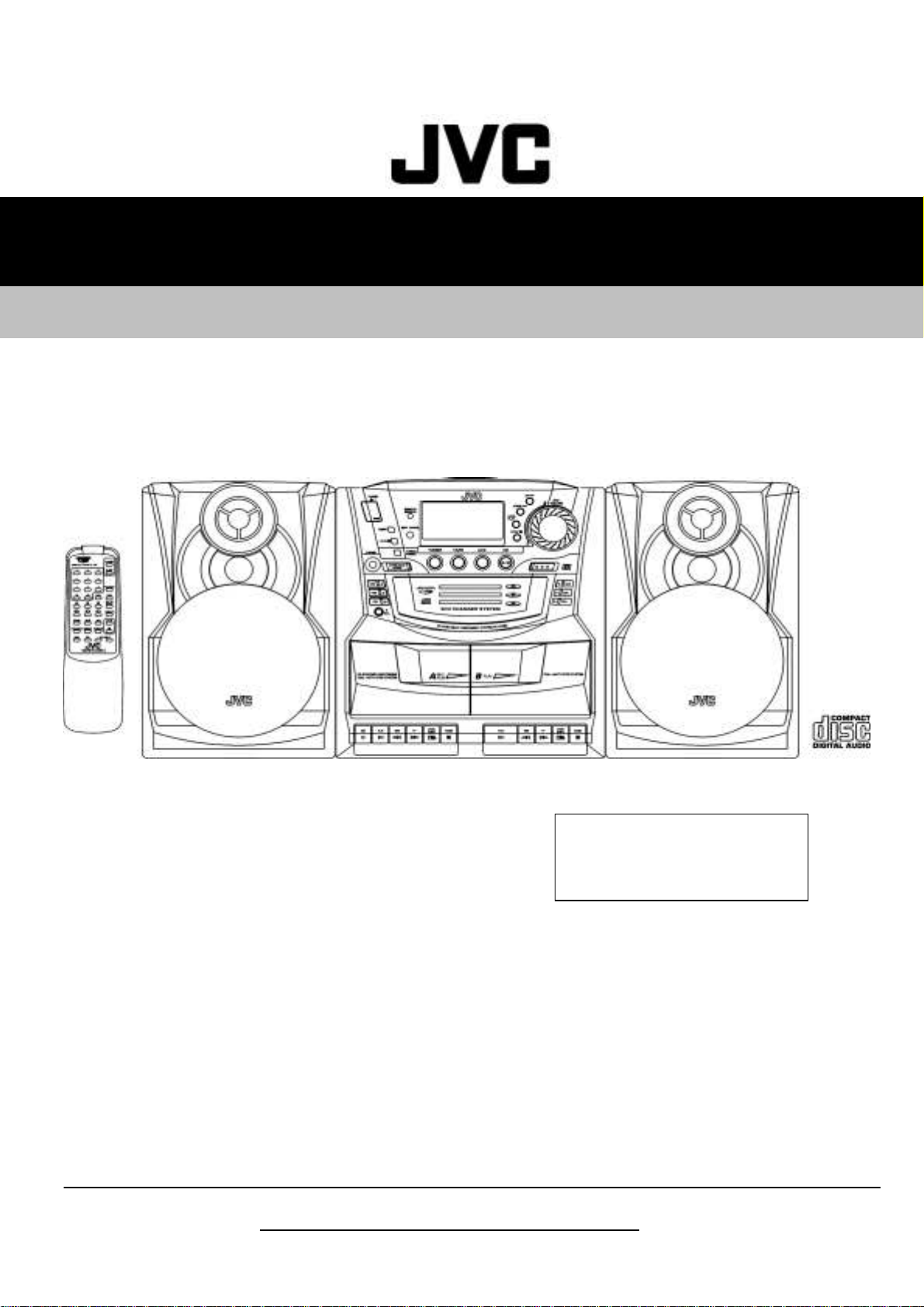
PC-XC350
SERVICE MANUAL
CD PORTABLE COMPONEMT SYSTEM
PC-XC350
Unit No.
SP-PCXC350
contents
Safety precaution ------------------ 1-2 Block/Wiring Diagram ----------------- 1-16
Disassembly method -------------- 1-4 Circuit Diagram ------------------------- 1-18
Adjustment method ---------------- 1-6 PCB drawing ---------------------------- 1-20
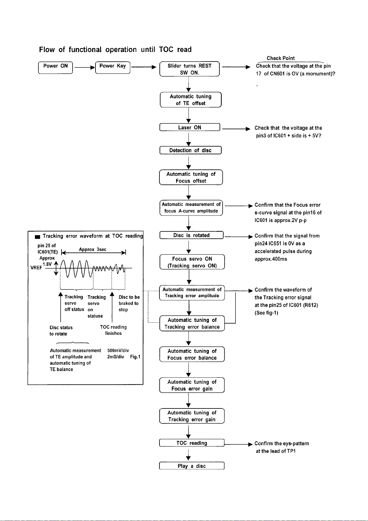
TOC read ---------------------------- 1-11 Assembly -------------------------------- 1-22
Major IC Description ---------------1-12 Packing ----------------------------------- 1-32
COPYRIGHT © 2001 VICTOR COMPANY OF JAPAN,LTD (By JCA)
Unit No.
SP-PCXC350
Area Suffix
J-----USA
C-----CANADA
Unit No.
SP-PCXC350
No. xxxxx
OCT 2001
Page 2
PC-XC350
Safety Precautions
1. This design of this product contains special hardware and many circuits and components specially for
safety purposes. For continued protection, no changes should be made ti the original design unless
authorised in writing by the manufacturer. Replacement parts must be identical to those used in the
original circuits. Services should be performed by qualified personel only.
2. Alterations of the design or circuitry of the product should not be made. Any design alterations of the
product should not be made. Any design alterations or additions will void the manufacturer's warranty
and will further relieve the manufacturer of responsibility for personal injury or property damage
resulting therefrom.
3. Many eletrical and mechanical parts in the products have special safety-related characteristics.
These characteristics are often not evident from visual inspection nor can the protection afforded by
them necessarily be obtain by using replaement components rated for higher voltage, the Parts
List of Service manual. Electrical components having such features ate identified by the shading on the
schematics and by ( ) on the parts List in the Service Manual. The use of a substitute
repalcement which does not have the same safety characteristics as the recommended replacement
parts shown in the Parts List of Service manual may create shock, fire, or other hazards.
4. The leads in the products are routed and dressed with ties, clamps, tubing's, barriers and the like to
be separated from live parts, high temperatures parts, moving parts and/or sharp edges for the
prevention of electric shcok and fire hazard. When service is required, the original leat routing and
dress should be observed, and it should be confirmed that they have been returned to normal, after
re-assembling.
5. Leakage current check (Electrical Shock hazard testing)
After re-assembling the product, always perform an isolation check on the exposed metap Parts of the
product (antenna terminals, knobs, metal cabinet, screw heads, headphone jack, control shafts, etc.)
to be sure the product is safe to operate without danger of electrical shock.
Do not use a line isloation transformer during this check.
Plug the AC line cord directly into the AC outlet. Using a "Leakage Current Tester", measure the
leakage current from each ecposed metal parts of the cabinet, particularly and exposed metal
part having a return path to the chassis, to a known good earth ground. Any leakage current must
not exceed 0.5mA AC (r.m.s.)
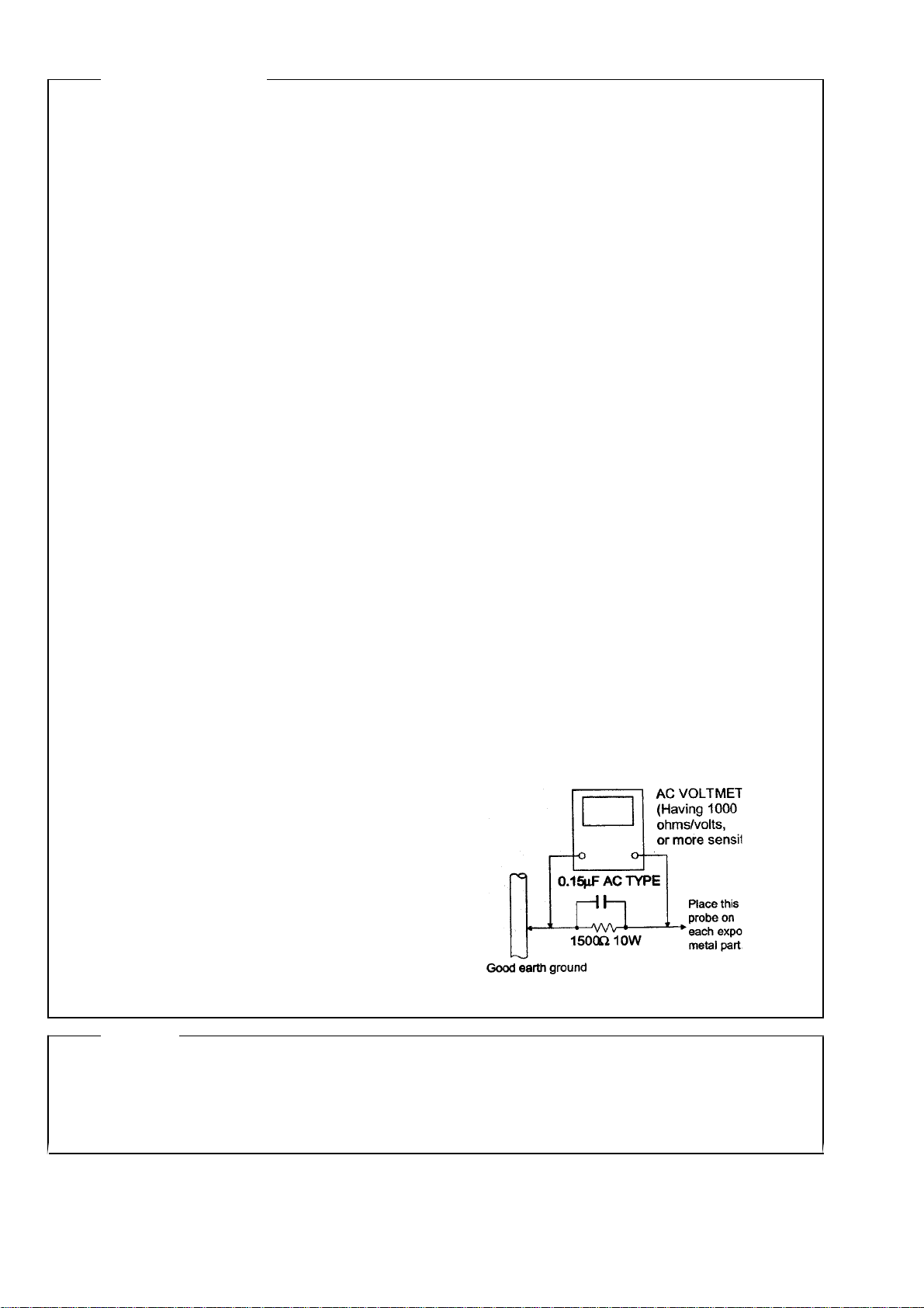
Alternate check method
Plug the AC line cord directly into the AC outlet. Use an AC voltmeter having, 1,000 ohms per
volt or more sensitvity in the following manner. Connect a 1,500 ohm 10W resistor paralleled by a
0.15uF AC-type capacitor between an exposed
metal part and a known good earth ground.
Measure the AC voltage across the resistor with
the AC voltmeter.
Move the resistor connection to each exposed
metal part, particularly and exposed metal part
having a return path to te chassis and
measure the AC voltage across the resistor. Now,
reverse the plug in the AC outlet and repeat
each measurement. Voltage measured Any must
not exceed 0.75 V AC (r.m.s.). This corresponds
to 0.5 mA AC (r.m.s.).
Warning
1. This equipment has been designed and manufactured to meet international safety standards.
2. It is the legal responsibility of the repairer to ensure that these safety standards are maintained.
3. repairs must be made in accordance with the relevant safety standards.
4. It is essential that safety critical components are replaced by approved parts.
5. It mains voltage selector is provided, check setting for local voltage.
CAUTION Burrs formed during moulding may be left over on some parts of the chassis. Therefore,
pay attention to such burrs in the case of performing repair of this system.
1 - 2
Page 3
PC-XC350
Preventing static electricity
Electrostatic discharge (ESD), which occurs when static electricity stored in the body, fabric, etc. is discharged,
can destroy the laser diode in the traverse unit (optical pcikup). Take care to prevent this when performing repairs.
1.1. Grounding to prevent damage by static electricity
Static electricity in the work area can destroy the optical pickup (laser diode) in devicessuch as DVD players.
Be careful to use proper grounding in the area where repairs are being performed.
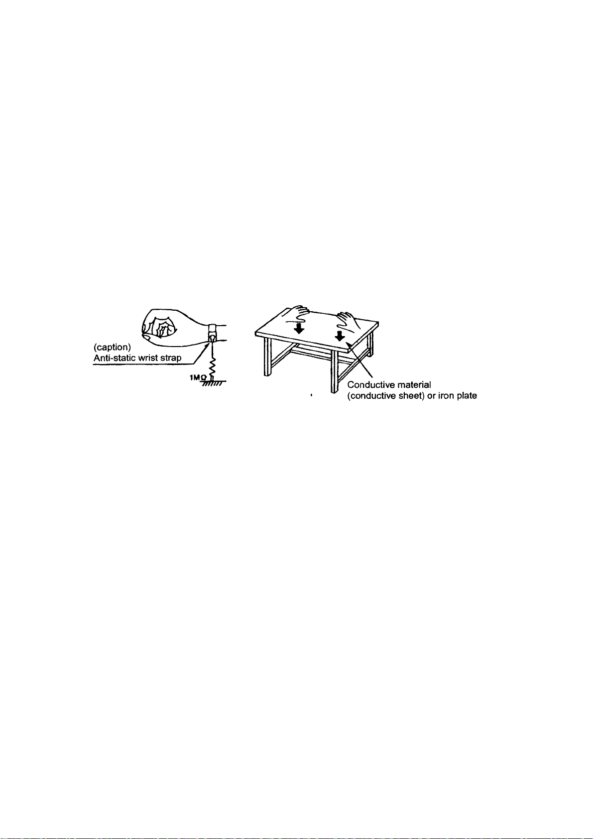
1.1.1. Gound the workbench
1. Ground the workbench by laying conductive material (such as a conductive sheet) or an iron plate over
it before placing the traverse unit (optical pickup) on it.
1.1.2. Ground yourself
1. Use an anti-static wrist starp to release and static electricity built up in your body.
1.1.3. Handling the optical pcikup
1. In order to maintain quality during transport and before installation, both sides of the laser diode on the
replacement optical pickup are storted. After replacement, return the shorted parts to their original condition.
(Refer to the text.)
2. Do not use a tester to check the condition of the laserdiode in the optical pickup. The tester's internal power
source can easily destory the laser diode.
1.2. Handling the traverse unit (optical pickup)
1. Do not subject the traverse unit (optical pcikup) to strong shocks, as it is a sensitive, complex unit.
Cut off the shorted part of the flexible cable using nippers, etc. after replacing the optical pickup. For specific
2.
details, refer to the replacement procdeure in the text. Remove the anti-static pin when replacing the traverse
unit. Be careful not to take too long a time when attaching itto the connector.
3. Handle the flexible cable carefully as it may break when subjected to strong force.
It is not possible to adjust the semi-fixed resistor that adjusts the laser power. Do not return it.
4.
1 - 3
Page 4
PC-XC350
Screw B.
Disaeesmbly method
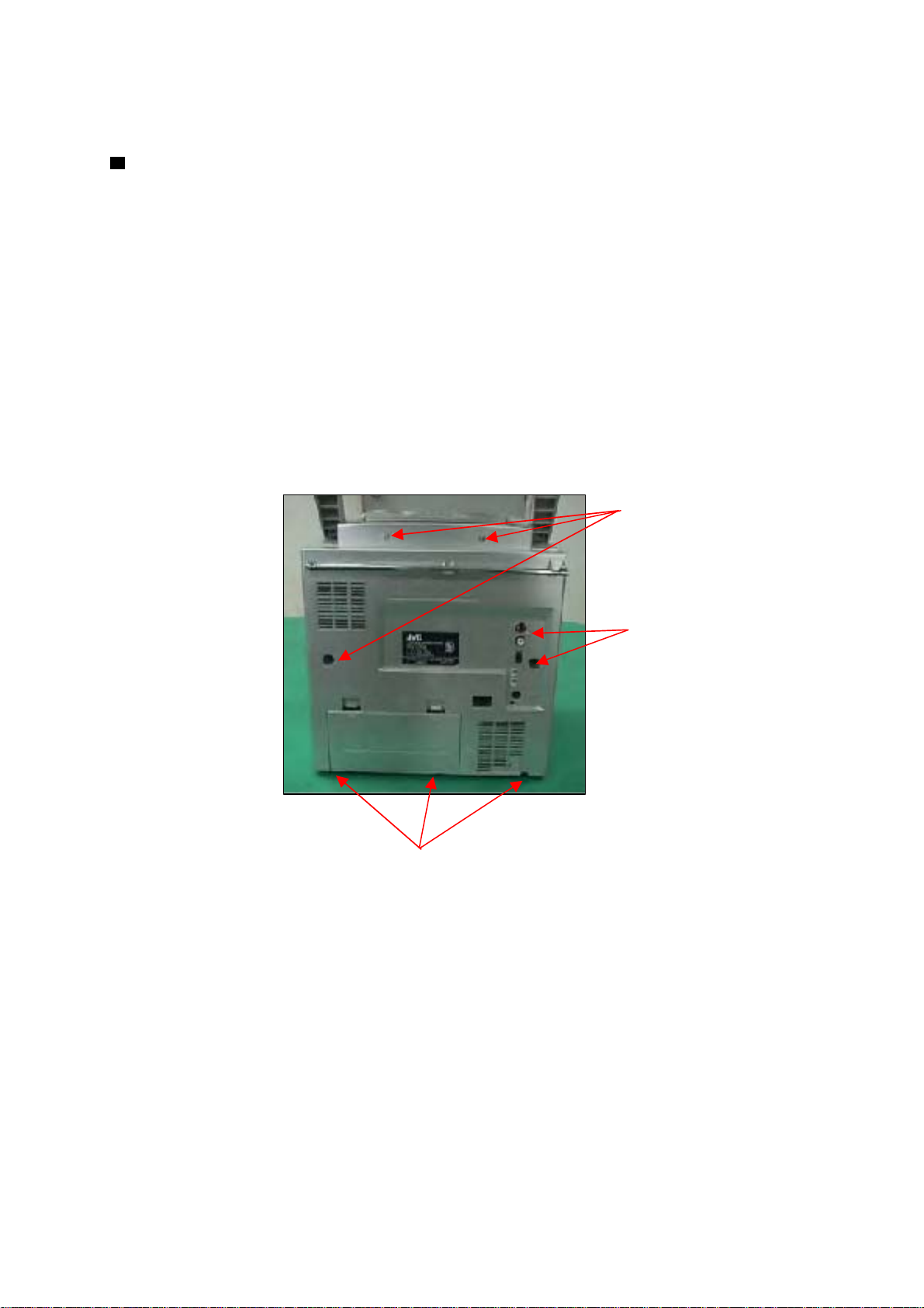
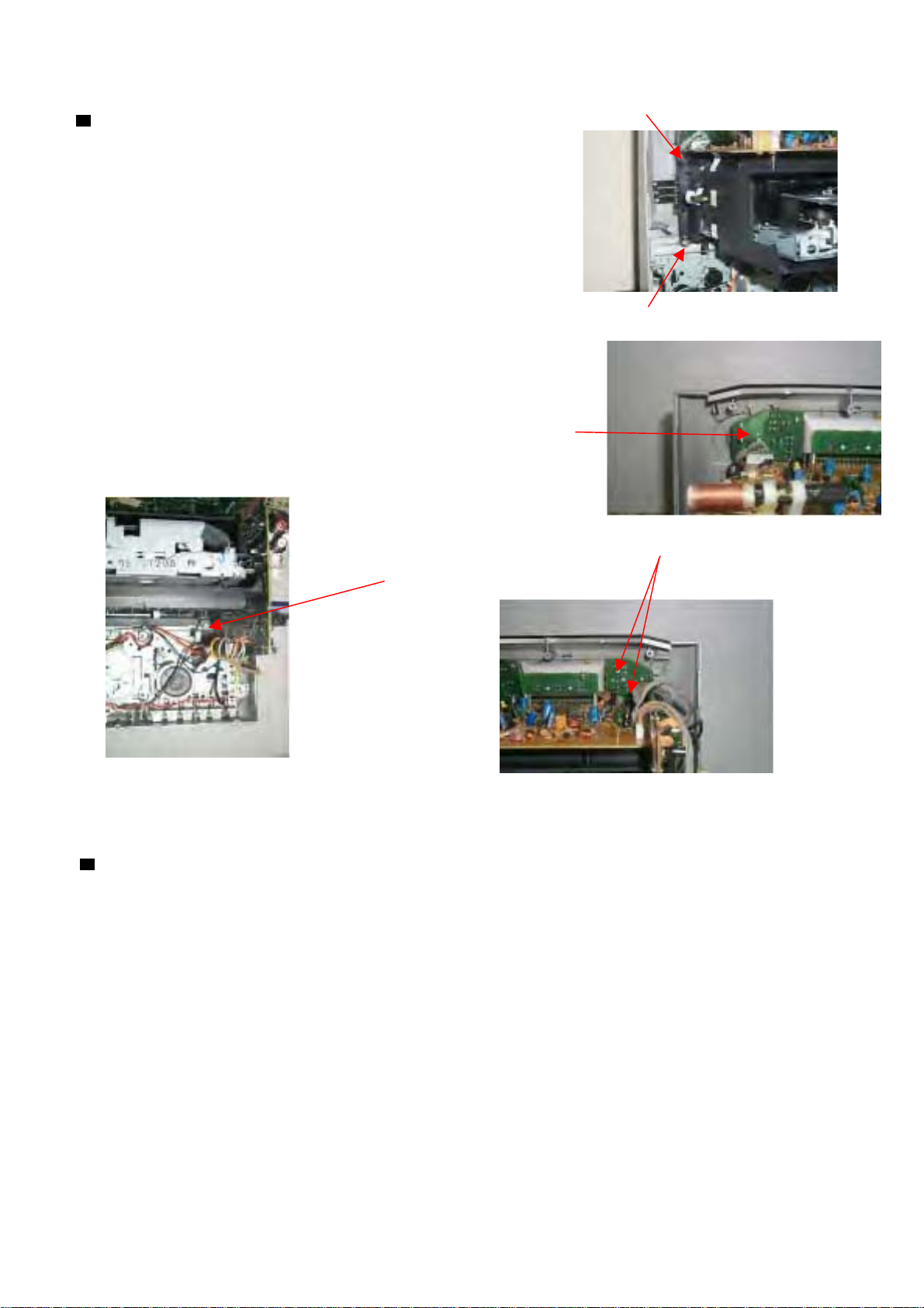
Removing the rear panel
1. From behind the body, remove the eight screws A
retaining the rear panel.
2. Then remove the two screws B retaining the rear panel.
3. Take out the rear panel from the body.
Note:
Be careful of the FM antenna white wire, it is connection with the tuner PCB up side.
You can directly take out from the tuner PCB.
When you re-assembly the product, plug the FM antenna white wire into the Tuner PCB's
"FM ANT" position.
Screw A.
Screw A.
1 - 4
Page 5
PC-XC350
Removing the CD mechanism
1. Remove the rear panel
2. Removing the two screws E retaing the 3CD
mechanism cover.
3. Removing the crew F retaing the control PCB
left side.
4. Remove the srews G retaing on the 3CD mechanism cover
& the two screws H retaining on the control PCB
F
E
E
G
H
Removing the Main PCB
1. Remove rear panel
2. Remove the 3CD mechanism
3. Remove the four screws attaching the
main PCB.
1 - 5
Page 6
PC-XC350
Adjustment method
Measurement instruments required for Tuner section
adjustment
Voltage applied to tuner ----- +B:DC 5.7V
1. Low frequency oscillator VT: FM 2~5v / am 1.5~7.5v
This oscillator should have a capacity to output Reference measurement ----- 26.1mV(0.866/3
0dB to 600 at an oscillation frequency of output
50Hz-20KHz Input positions ----- AM : Standard loop antenna
FM : TP1 (hot) and TP2 (GND)
2. Electronic voltmeter
3. Distorion meter
4. Frequency counter Standard measurement position of volumett
5. Wow & flutter meter
6. Test tape Bass ---------------------- Off
TCC-112: tape speed and running unevenness (3KHz) EQ ----------------------- Flat
TCC-140: Reference level (1KHz) UP and down adjustment of volume ----- Vol : 16
TCC-182A: Head angle (8KHz), playback frequency
characteristics (1KHz) and dubbing frequency Precautions for measurement
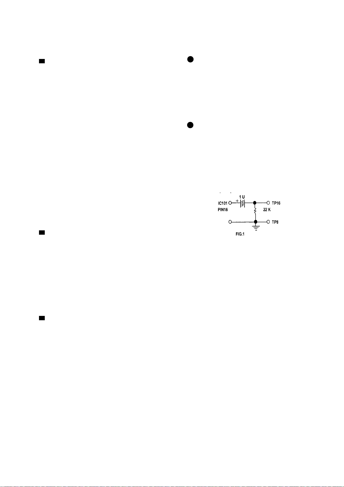
charateristics (125Hz and 8KHz) 1. Direct connect to the IF sweeper output
side and 1 UF and 22 Kohm connect to the
7. Black tape sweeper input side. Same as FIG. 1.
TYPE I : TDK-D60
8. Torque gauge : For play and tension
FWD(CT-120m), and FF/REW(CT-F)
Measurement conditions
Power supply voltage----------AC 120V (60Hz)
Reference output----------Speaker : 0.866V/3 2. The IF sweeper output level should be made as
Headphone : 0.245V/32 low as possible within the adjusttable range.
Reference frequency and -----1KHz, AUX : 450mV 3. Since the IF sweeper is a fixed device, there is no
input level need to adjust this sweeper.
Input for confirming recording and-----CD : -10dB 4. Since a ceramic oscillator is used, there is no need
playback characteristics to perform and MIX adjustment.
Measurement output terminal-----Speaker CN301 5. Since a fixed coil is used, there is no need to
*Load resistance----------------------3 adjust the FM tracking.
6. The input and output earth systems are separated.
In case of simuitaneously measuring the voltage in
Radio Input signal both of the input and output systems with an
electronic voltmeter for two channels, therefore, the
AM frequency ----------------400Hz earth should be connected particularly carefully.
AM modulation-----------------30% 7. In the case of BTL connection amp., the minus
FM frequency -----------------1 KHz terminal of speaker is not for earthing. Therefore, be
FM frequency deviation --------22.5KHz sure not to connect any other earth terminal to this
terminal. This system is of an BTL system.
8. For connecting a dummy resistor when measuring
the output, use the wire with a greater code sze.
9. Whenever any mixed tape is used, use the band
pass filter (DV-12V)
1 - 6
Page 7
TUNER ADJUSTMENT
use a plastic screews driver for adjustments.
Adjust the intermediate frequency of AM and FM to the frequency of cermic filter.
Supply voltage: DC 12.0V
Speaker impedance: 3 OHMS
Function switch: RADIO
PC-XC350
a. AM adjustment BAND SELECT SWITCH : AM
ste Adjusting Tuning Adjustment
circuit Frequency Measurement input Measurement output parts
1 IF 1000 KHz AM Sweep Loop VTVM TP16 (H) T103
(450 KHz) Generator ANT Oscilloscope TP 8 (E)
2 Tuning 530 KHz Digital TP16 (H) T102
3 Coverage 1710 KHz Voltmeter TP 8 (E)
4 Tracking 600 KHz Am signal Loop VTVM TP12 (L) MW COIL
5 1500 KHz Generator ANT Oscilloscope TP11 (R) CT102
b. FM Adjustment BAND SELECT SWITCH : FM FM Dummy Antenna : 75 ohm unbalance
ste Adjusting Tuning Adjustment
circuit Frequency Measurement input Measurement output parts
1 IF FM Sweep TP4 (H) VTVM TP16 (H)
(10.7 MHz) 98.0 MHz Generator TP8 (E) Oscilloscope TP8(E) T104
2 Tuning 87.5 MHz Digital TP16 (H)
3 Coversage 108 MHz -- -- Voltmeter TP8(E) L104
4 Tracking 90.0 MHz FM Signal FM ANT VTVM TP12 (L) L103
5 106.0 MHz Generator TP1(E) Oscilloscope TP11 (R)
Input Connection Output Connection VTVM Oscilloscope
Output ConnectionInput Connection VTVM Oscilloscope
1.2+/-0.05V
Confirm 7.0+/-0.5V
Maximum
Confirm 1.4+/-0.1V
5.6+/-0.5V
Confirm with being
near by effective
sensitvity
1 - 7
Page 8
PC-XC350
ARRANGEMENT OF ADJUSTMENTS POSITION
1 - 8
Page 9
PC-XC350
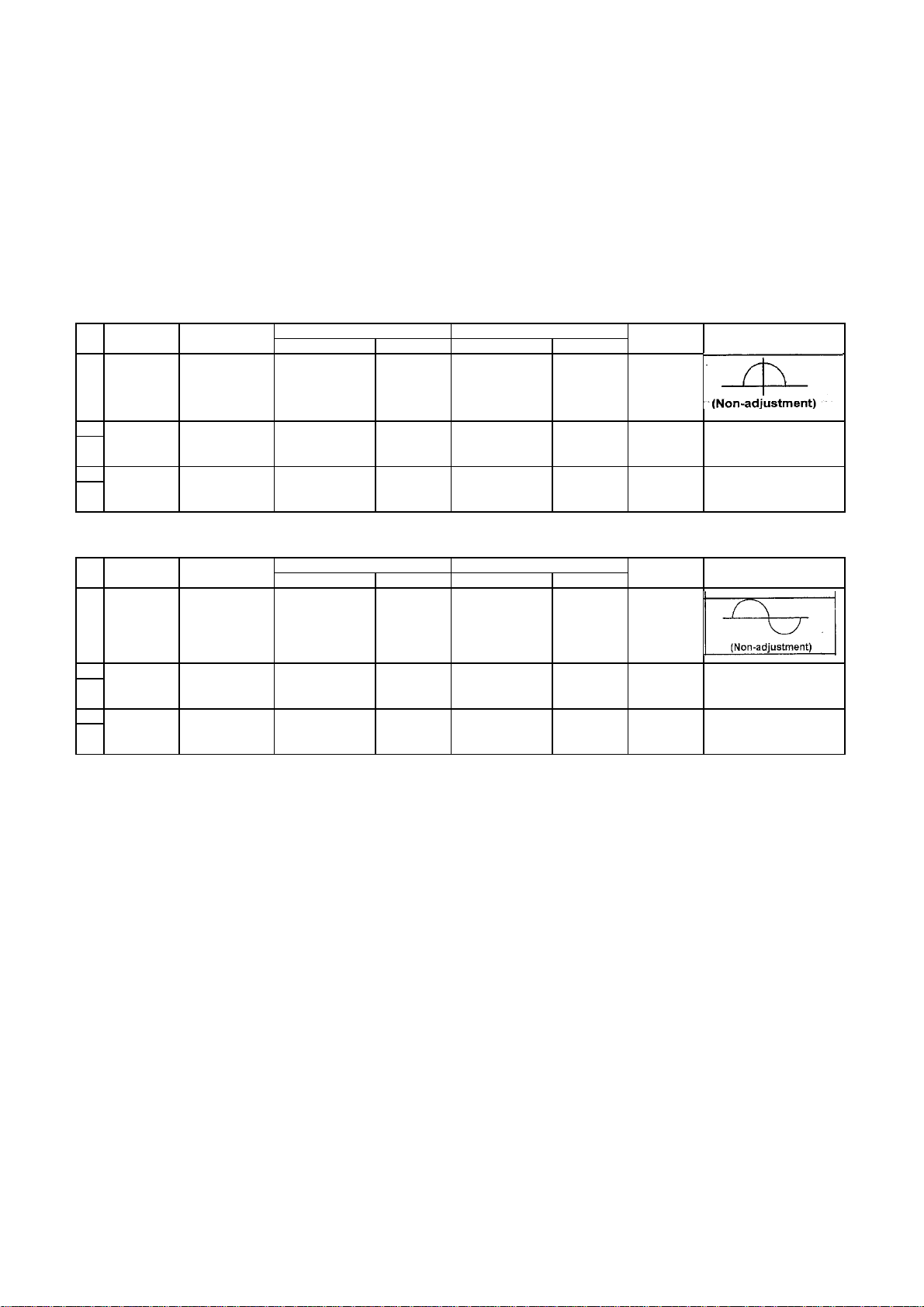
Tape recorder section
Items Measurement Measurement method Standard Adjusting
conditions Values position
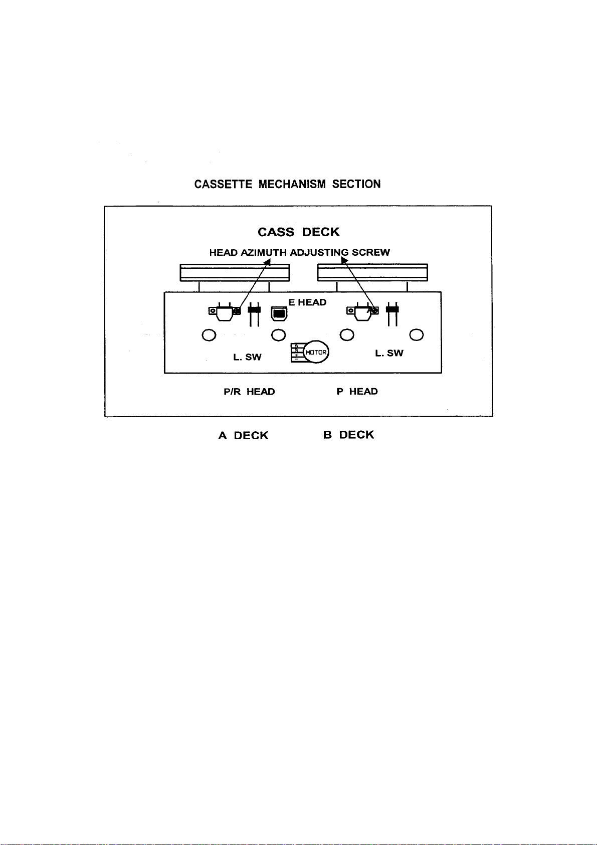
Confirmation Test tape 1 Playback the test tape TCC-182A (8KHz) Maximum Adjust the head
of head angle : TCC-182A(8KHz) 2 With the recording & playback mechanism, output azimuth screw
Confirmation Test tape Adjust VR401 so that the frequency counter Tape speed VR401
of tape speed : TCC-112 (3KHz) reading becomes 3,010Hz +/-15Hz when of deck
Measurement output adjust the head azimuth screw so that the only
terminal left and right output leavers become
: Speaker terminal maximum, After adjustment, lock the head
Speaker R/L azimuth at least by half turn.
(Load resistance: 3
: Headphone terminal
playing back the test tape TCC-112 (3KHz) with :3,010Hz
playback and recording mechanism after +/-15Hz
Measurement output ending forward winding of the tape.
terminal
: Headphone terminal
Referemce Values for Confirmation Items
Items Measurement
conditions Values position
Wow & flutter Test tape When the test tape TCC-112 (3KHz) has been 0.25% or
:TCC-112(3KHz) played back with the recording and playback less
mechanism at the beginning of forward (WRMS)
winding, the frequency counter reading of
Measurement output wow & flutter should be 0.25% or less
terminal (WRMS).
:Headphone terminal
Measurement method
Standard Adjusting
1 - 9
Page 10
PC-XC350
Electrical Performance
Items Measurement Measurement method Standard Adjusting
conditions Values position
Adjustment of Mode: Playback 1 With the recording and playback
recording blas mode mechanism, load the test tapes TDK-D60
current Recording mode TDK-D60, and set the mechanism to the 4.5 u A
(Reference Test tape recording and pausing condition in advance. +/-0.5u A
Value) TDK-D60
Adjustment of Reference frequency 1 with the recording and playback Output
recording and :1KHz and 8KHz mechanism, load the test tapes (TDK-D60) deviation
palyback (REF.:-10dB) and set the mechanism to the between
frequency Test tape recording and pausing condition in 1KHz and
characteristics TDK-D60 advance 8KHz
Measurement output 2 After connecting 100 in series to the
terminal recorder head, measure the blas current
: Both recording and with a valve voltmeter at both of the
headphone terminals terminals
Measurement input 2 While repetitively inputting the reference :-1dB +/-2dB
terminal frequency signal of 1KHz and 8KHz from
: OSC IN OSC IN, record andplayback the tape.
3 While recording and playback the test tape
Lch and Rch so that the output
deviation between 1KHz and 8KHz from
-1dB +/-2dB
Reference Values for Electrical Function Confirmation Items
Items Measurement Measurement method Standard Adjusting
conditions Values position
Recording Playback 1 While changing over t and form BIAS 1 64KHz T201
blas Test tape and 2, confirm that the frequency is +/-6KHz
frequency TDK-D60 changed.
Measurement 2 With the recording and playback
terminal : BIAS TP on mechanism, load the test tape.
P.C. board (TDK-D60), and set the
mechanism to the recording and pausing
condition in advance.
3 Confirm that the BIAS TP frequency on the
P.C. board is 64KHz +/-6KHz
1-10
Page 11
PC-XC350
1-11
Page 12
PC-XC350
DESCRIPTION OF MAJOR IC
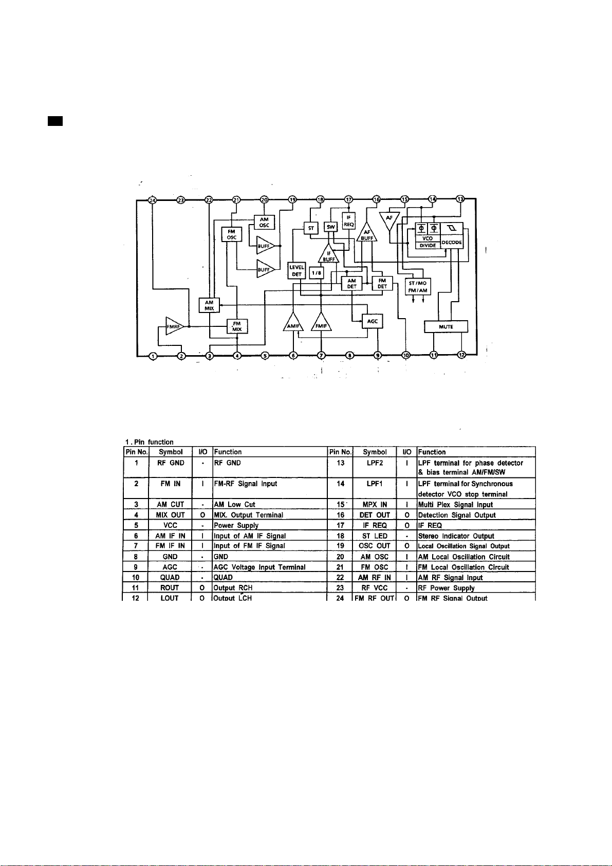
TA2104BN (IC101) AM/FM 1 CHIP TUNER
Block Diagram
1-12
Page 13
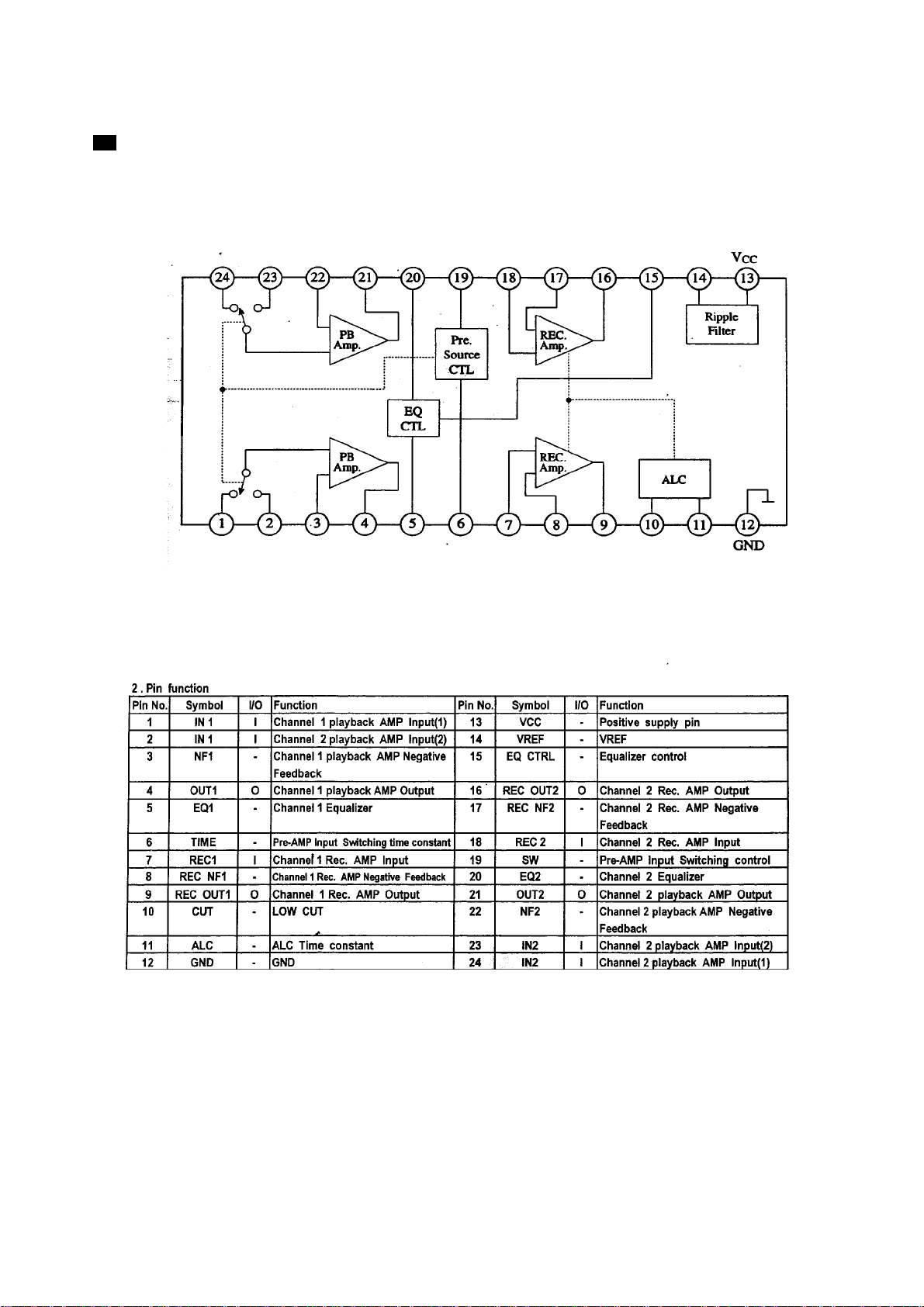
AN7345K (IC201) DUAL RECORD/PLAYBACK PRE-AMPLIFIER
Block Diagram
PC-XC350
1-13
Page 14
PC-XC350
1 - 14
Page 15

PC-XC350
1 - 15
Page 16

PC-XC350
BLOCK DIAGRAM
1 - 16
Page 17

WIRING DIAGRAM
PC-XC350
1-17
Page 18

PC-XC350
R431
C223
R217
C217
54123
GND
P/R CONT
R/B(+)-CONT
CN501
TO AUDIO BOARD
1 - 18
Q207
10K
470U
22K
332M
MU(1)-I/P
R516
9014
C242
R233
C213
MU(2)-I/P
100K
153M
220
222M
1
2
3
4
5
6
7
8
9
10
11
12
IC302 BA5417
13
14
15
IC301 BA15218N
VOL
153M
22K
R207
22
4U7
C219
BASS
560
1
2
3
4
5
6
7
8
TREBLE
1K5
R503
R231
C237
Circuit Diagram- 1
JACK2
JK301
L/SP.
7123654
R
120
R341
C319
2200U/16V
C318
47U
270
R323
4U7
C311
27k
R313
1U
C337
R517
100K
R515
150K
R510
R512
L
120
R342
C320
C321
154M
2200U/16V
4.7
R327
C317
47U
270
R324
C314
500P
220
R317
Q303
1936
R315
10K
47U
C339
1U
C305
1U
C306
180K
R307
R308
180K
C302
C304
823M
823M
15K
R347
1.5K
R345
2K2
R519
1U
C519
13
14
0.47U
15
C520
16
0.1U
C521
C514
17
103M
18
19
C512
683M
20
21
C510
683M
22
0.1U
C508
4K7
23
24
10K
10U
C516
C506
102M
GND
2
1
C322
154M
R328 4.7
R329 22K
R330 22K
R326 10K
1U
C324
47U
C315
500P
C313
4U7
C312
220
R318
Q304
1936
27k
R314
R303
C303
823M
R349
10K
R301
1.8K
1.8k
R302
C301
823M
47U
C340
10K
2K2
R348
R304
R309 100
470U
C307
R518
2K2
12
11
R514
100K
10
9
8
7
BH3852SIC502
6
5
4
3
0.1U
C507
2
1
C323
R310
L.SPK
220U
C515
GND
R.SPK
R/SP.
2
1
!
Q401
1U
R331
470K
C325 104M
D302
IN4148
4U7
C329
104
C402
47U
C316
47U
C334
9014
Q306
10K
R333
R316
10K
D303
IN4148
2K2
R305
1K
15K
R346
1.5K
R344
100U
C513
103M
C511
683M
C509
683M
C505
102M
R312
10k
R311
C308 47U
10k
R306
9014
Q301
4V3
D301
1U
C338
4U7
C518
C517 473M
9014
Q307
100
R513
4K7
R509
10K
R511
22K
C326
R325
D305
9014
Q309
IN4148
2K7
R332
22K
R335
22K
R334
Q302
4K7
4K7
R438
R343
100K
2K2
R339
R340 10
9015
Q305
C327
9014
D304
IN4148
3K9
R336
33K
R337
R338
150K
R439 100
330
C418
8050
Q416
Q308
10K
R478
9014
Q415
10K
R459
4U7
10U
C429
Q421
9014
D424
IN4148
D426
IN4148
C426 22U
C428
0.47U
22U
C427
R452
10K
R457
10K
10K
R455
C410
6V8
D409
470U/25V
100U
D412
IN4148
B764
9015
C404
100U/25V
D427
IN4148
10K
R464
D425
IN4148
R456
10K
R466
10K
10K
0.47U
R458
C415
47K
R449
Q424
9014
10K
R453
2K2
R454
R419
4.7 1/2W
13
!
2
IC401
KIA7808
R450
10 1/2W
10K
R442
10V
D411
9015
Q419
56K
R451
D407
IN4148
8050
Q420
D419
IN4148
Q403
9014
150
R401
R405
4.7U
C331
103
C330
D310
IN4148
R418
10 1/2W
C408
330
R448
8050
Q408
!
B764
Q409
Q413
330
R430
560P
R429
C416
10K
R428
R434
9014
Q414
1U
22K
R435
C417
C424 100U/25V
10K
R443
220U
C411
120
R447
D420
120
R445
C421
47U
C422
100U
C423
C401
4700U/25V
27K
R404
103
22K
C406
1K
R407
100U
9.1V
D403
R420
2.2 1/2W
9014
27K
22K
R446 1K5
6V8
47U
R421
Q423 9015
D418 IN4148
10
C412
100U/25V
R426
Q411
R430
4.71/4W
1K
R436
10K
R425
47K
R462
D417
IN4148
D421 5V1
10K
9014
Q501
5K6
R230
C214
1U
C602
0.1U
C501
C225 102M
D201 IN4148
1K5
R209
1U
C209
R205 3K3
R203
100U
C203
332M
102M
332M
18K
R215
R213
1936
Q201
A
A
R437
9014
Q206
4K7
R505
10K
R463
R507
120K
100K
0.1U
C211
3K9
R201
C205
333M
C201
R227 100
12
13
22U
C221
R237
22U
C215
220P
C207
11
14
10
15
9
16
8
17
7
18
6
19
5
20
4
21
IC201 AN7345K
3
22
2
23
1
24
C239
CN201
BA3126NIC202
3 PIN
L/CH
P/B HEAD
9
8
7
6
5
4
3
2
1
470
R/CH
P/B HEAD
B DECK
4K7
R506
Q502
R433 10K
C503
4.7U
220
R234
C243
153M
393M
C222
22U
C216
0.1U
C502
0.1U
C212
3K9
R202
220P
C208
C206
333M
332M
220
R219
C230
100U
R/CH
R/P HEAD
22U
102M
C226
5K6
10U
C218
1K5
R210
1U
C210
100U
C204
22
C238
102M
C202
R226
R216 18K
8050
Q203
1K
R221
1K
R220
5PIN
CN202
L/CH
R/P HEAD
A DECK
1K5
R504
9014
120K
R218 33K
C227
C244 153M
R235 560
R502
22K
R208
3K3
R206
R204
R508
8
332M
C224
C241
222M
7
6
5
4
3
IC501 BA15218N
2
1
C240 332M
1936
390P(NPO)
500P
500P
Q202
R214
104
C236
4U7
C220
1K
C232
C229
C228
D414 IN4148
4.7U
C504
R533 100
C527
100K
R530
R531
470
3K3
R222
R225
T201
100U
15P
10K
47U
R532
C526
C525
R534
10K
1U
C522
15P
100K
C524
C523 1U
R212 6.8K
R211 6.8K
10K
R470
10U
C420
4.7
R224
8050
Q204
10K
R223
C234
103M
C233
223M
10
3630
C246
C235
220U
C231
472M
R237
CN203
TO R/P SW. BOARD
R440
Q417
D416
IN4148
10U
22K
R228
560
54123
GND
P/R CONT
R/B(+)-CONT
2K7
8050
9015
Q205
MU(1)-I/P
MU(2)-I/P
100U
C419
5V6
D410
22K
R441
CN502
68K
68K
6.8K
R521 6.8K
R536
R520
R535
47K
R537
47K
R538
12345
P-GND
TU-RCH
TU-LCH
CD-LCH
TO TUNER BOARD
678
TU-5V
CD-RCH
CD-5V
D406
8V
560
8050
C413
C413
IN4148
9
GND(1)
100U/25V
D413
100U/16V
D415
VR401
10K
10GND(2)
11
LP-SW.
Q412
IN4148
!
DC 12V
!
DC
223
*FS1101
C1101
T2.5A L 125V
!
D1101
IN5401
D1103
IN5401
!
223
C1103
!
D1102
D1104
C1105 6800U/25V
CN1101
!!
!
IN5401
IN5401
T1101
EI-48 POWER TF.
223
C1102
223
C1104
AC
123
GND
AC-(+)12V
DC-12V
GND
AC-(+)12V
DC-12V
123
10K
R422
C414
100U/25V
6V8
D405
6V2
D404
R423
100K
103
C425
9014
68K
R424
47K
R539
IN4148
5K6
R417
R523 8.2K
R522 8.2K
R526 30K
R527 30K
CONT.B+ 12
JK501
LEAF SW. (B DECK)
9014
Q505
R525
R524 2K2
9014
Q503
47K
R528
PHOLEJACK2
MM+
A
MT1
B
DS-M
6
(+)12V
M(+)
5
GND
4
A
3
B
R468
VOL
TRE
BASS
150P
C528
2K2
9014
Q504
R529 47K
2
1
8
7
6
5
4
3
2
1
CD SIGNAL
AUX SIGNAL
2.2 1/2W
6
5
4
3
2
1
9
8
7
6
5
4
3
2
1
CN402
L.S.(B)
TO MAIN BOARD
GND
SAFETY
PWR.OUT
FUN.CD
BATT.
AC/DC
CN403
DC 6V
DC 12V
TO MI-COM BOARD
A DECK SIGNAL
B DECK SIGNAL
REC SIGNAL
MAIN SIGNAL
TUNER SIGNAL
TAPE MAIN SIGNAL
(+)12V
M(+)
GND
CN402
A
B
TO CASSETTE DECK
L.S.(B)
SMUTE
AHB
FUN.AUX
FUN.TU
REC B+
TRE
CN404
VOL
BASS
TO MI-COM BOARD
SW8V
HAVE CRITICAL
!
3). COMPONENTS MARKED WITH
1).DISCONNECT POWER CORD BEFORE SERVING.
2). RECOMMEND THE UNIT BE OPERATED BY DC 12 VOLTS DURING TROUBLE SHOOTING.
CHARACTERISTICS. ONLY REPLACE WITH THE COMPONENT OF THE SAME TYPE NUMBER.
4). SUBJECT TO CHANGE WITHOUT NOTICE.
Page 19

Circuit Diagram- 2
PC-XC350
1 - 19
Page 20

PC-XC350
Printed Circuit Board- 1
1 - 20
Page 21

PC-XC350
Assembly- 1
09
S4
01
05
S3
02
04
S2
06
08
S5
07
S1
03
1 - 22
Page 22

Assembly- 1
PC-XC350
ITEM Q'TY
!
01 535-026800-000 REMOTE RECEIVER BRACKET 1
02 248-350003-103 CONTROL BOARD 1
03 357-000033-123 CD DECK 1
04 408-146395-150 HEAT SINK 1
05 454-000030-050 NUT M3 1
06 248-350001-104 TUNER BOARD 4
07 535-147000-000 CD TRAY 1
08 248-350008-100 LIGHT BOARD 1
09 535-131064-000 DISPLAY BRACKET 1
S1 238-130150-602 SCREW 3 x 15 PB 7 FROM CD TRAY TO FRONT CABINET
S2 238-230080-203 SCREW 3x8BM 4 FIX THE TUNER BOARD
S3 238-130086-202 SCREW 3 X 8 BB ( HARD ) 1 FIX HEAT SINK
S4 238-130080-602 SCREW 3 X 8 PB 4 FIX THE TUNER BOARD
S5 238-130100-602 SCREW 3 x 10 PB 4 FROM CD DECK TO CD TRAY
PARTS NAME DESCRIPTION/LOCALITYPART NO.
1 - 23
Page 23

PC-XC350
Assembly- 2
S9
S8
31
25
26
27
28
24
S7
30
29
S5
22
S6
20
12
23
17
S3
21
19
S1
S4
16
05
18
S2
07
08
15
14
13
04
1 - 24
06
11
01
03
09
02
10
Page 24

R
Assembly- 2
PC-XC350
ITEM Q'TY
!
PARTS NUMBER PARTS NAME DESCRIPTION/LOCALITY
01 525-073030-011 RIGHT CASS DOOR LENS 1
02 525-072030-011 LEFT CASS DOOR LENS 1
03 525-0030S3-012 LEFT CASS DOOR 1
04 525-0130S3-012 RIGHT CASS DOOR 1
05 766-250000-000 LEFT CASS DOOR SPRING 1
06 525-029300-000 LEFT CASS TAPE BRACKET 1
07 766-250000-000 RIGHT CASS DOOR SPRING 1
08 525-029300-000 RIGHT CASS TAPE BRACKET 1
09 525-080400-013 CD DISPLAY LENS 1
10 500-810200-011 "JVC" NAME PLATE 1
11 535-145430-012 DISPLAY PANEL 1
12 535-1010S3-012 FRONT CABINET 1
13 535-149017-012 CD DOOR 1
14 535-1803S3-000 CD DOOR LENS 1
15 535-1074S3-000 VOLUME KNOB 1
16 539-121200-000 LEFT CASS DOOR GEAR HOLDER 1
17 539-121100-000 LEFT CASS DOOR GEAR 1
18 539-121200-000 RIGHT CASS DOOR GEAR HOLDE
19 539-121100-000 RIGHT CASS DOOR GEAR 1
20 525-0102S3-012 LEFT CASS KNOB 1
21 525-0108S3-012 RIGHT CASS KNOB 1
22 463-380000-000 LEFT CASS KNOB PLATE 1
23 463-380000-000 RIGHT CASS KNOB PLATE 1
24 535-150417-012 CD DOOR OPEN KNOB 4pcs/KIT
25 535-1510S3-000 POWER KNOB 1
26 535-1520S3-000 TIMER CONTROL KNOB 4pcs/KIT
27 535-1516S3-013 FUNCTION KNOB 6pcs/KIT
28 535-1060S3-000 TURNER CONTROL KNOB 4pcs/KIT
29 535-150317-011 CD PLAY KNOB 3pcs/KIT
30 248-250813-000 RECORDING BOARD 1
31 156-255609-254 CASS DECK 1
S1 238-120060-602 SCREW 2 X 6 PB 1 FIX LEFT TAPE BRACKET
S2 238-120060-602 SCREW 2 X 6 PB 1 FIX RIGHT TAPE BRACKET
S3 238-130080-632 SCREW 3 X 8 PWB 1 FIX LEFT CASS DOOR GEAR
S4 238-130080-632 SCREW 3 X 8 PWB 1 FIX RIGHT CASS DOOR GEAR
S5 238-130060-602 SCREW 3 X 6 PB 3 FIX LEFT CASS KNOB PLATE
S6 238-130060-602 SCREW 3 X 6 PB 3 FIX RIGHT CASS KNOB PLATE
S7 238-220050-903 SCREW 2 X 5 MC 2 FIX THE RECORDING BOARD
S8 238-130100-602 SCREW 3 X 10 PB 6 FIX CASS DECK
S9 238-130100-632 SCREW 3 X 10 PWB 4 CD DOOR TRAY TO FRONT CABINET
1
1 - 25
Page 25

PC-XC350
Assemly- 3
S2
S3
02
04
01
S1
03
05
S4
12
08
S5
07
13
06
11
09
10
1 - 26
Page 26

Assembly- 3
PC-XC350
ITEM Q'TY
!
!
!
!
01 158-000117-622 AC SOCKET 1
02 500-025100-000 AC SOCKET COVER 1
03 152-112560-225 POWER TRANSFORMER 1
04 248-250812-100 RECTIFIER BOARD 1
05 525-0020S3-012 BACK CABINET 1
06 763-250000-000 BATTERY SPRING ( +/-- ) 1
07 764-701300-000 BATTERY SPRING ( +) 1
08 765-901000-000 BATTERY SPRING ( -- ) 1
09 763-455000-000 BATTERY SPRING ( +/-- ) 1
10 763-331800-000 BATTERY SPRING ( +/-- ) 1
11 525-0040S3-000 BATTERY DOOR 1
12 466-756350-050 1 COVER THE VOLTAGE SELECTOR HOLE
PART NO.
PARTS NAME DESCRIPTION/LOCALITY
PVC PLATE FOR VOLTAGE
SELECTOR HOLE
13 155-420026-238 RADIO ANTENNA 1
S1 238-130200-632 SCREW 3 X 20 PWB 2 FIX POWER TRANSFORMER
S2 238-128120-602 SCREW 2.8 X 12 PB 2 FIX AC SOCKET COVER
S3 238-130080-602 SCREW 3 X 8 PB 1 FIX RECTIFIER BOARD
S4 238-128120-602 SCREW 3 X 10 PB 1 FIX AUX JACK
S5 238-130100-203 SCREW 3 X 10 BM ( BLACK ) 1 FIX RADIO ANTENNA
1 - 27
Page 27

PC-XC350
Assembly- 4
01
S2
S1
1 - 28
Page 28

Assembly- 4
PC-XC350
ITEM Q'TY
!
1 525-0050S3-000 HANDLE 1
S1 238-130250-602 SCREW 3 X 25 PB 8 FROM FRONT CABINET TO BACK CABINET
S2 238-130100-602 SCREW 3 X 10 PB 1 FIX THE AUX JACK
PARTS NAME DESCRIPTION/LOCALITYPART NO.
1 - 29
Page 29

PC-XC350
Assembly- 5
02
S1
07
04
S2
03
06
S3
01
Assembly- 6
05
1- -30
Page 30

Assembly- 5
FOR RIGHT SPEAKER BOX ASSEMBLY
PC-XC350
ITEM Q'TY
!
01 500-810200-011 "JVC" NAME PLATE 1
02 525-040000-000 SPEAKER NET HOLDER 1
03 525-0410S3-010 SPEAKER BOX PANEL 1
04 154-178450-329 LOUD SPEAKER 1
05 154-508380-609 SPEAKER 1
06 525-026900-000 SPEAKER CORD HOLDER 1
07 525-0390S3-008 RIGHT SPEAKER BOX BACK 1
S1 238-130300-602 SCREW 3 X 30 PB 6
S2 238-130080-632 SCREW 3 X 8 PWB 4 FIX THE SPEAKER
S3 238-130080-632 SCREW 3 X 8 PWB 2
FOR LEFT SPEAKER BOX ASSEMBLY
ITEM Q'TY
!
01 500-810200-011 "JVC" NAME PLATE 1
PART NO.
PART NO. PARTS NAME DESCRIPTION/LOCALITY
NAME DESCRIPTION/LOCALITY
PARTS
FROM SPEAKER PANEL TO SPEAKER BOX BACK
FIX THE LOUD SPEAKER
02 525-040000-000 SPEAKER NET HOLDER 1
03 525-0410S3-010 SPEAKER BOX PANEL 1
04 154-508380-609 SPEAKER 1
05 154-178450-329 LOUD SPEAKER 1
06 525-026900-000 SPEAKER CORD HOLDER 1
07 525-0390S3-002 LEFT SPEAKER BOX BACK 1
S1 238-130300-602 SCREW 3 X 30 PB 6
S2 238-130080-632 SCREW 3 X 8 PWB 4 FIX THE SPEAKER
S3 238-130080-632 SCREW 3 X 8 PWB 2
FROM SPEAKER PANEL TO SPEAKER BOX BACK
FIX THE LOUD SPEAKER
1 - 31
Page 31

PC-XC350
Packing
MADE IN CHINA
P.14
P.15
P.2
P.1
P.12
P.13
P.3
P.4
P.5
P.6
P.7
P.11P.10
P.8
P.9
P.16
P.17
P.18
1 - 32
P.20
P.19
P.21
P.22
Page 32

Packing List
Item Part's Name Parts No.
PC-XC350
P.1 Poly Bag
RC37-400S3-010
P.2 Remote Control Unit
P.3 Instruction Manual
P.4 Warranty Card
P.5
Registration card
601-351000-010
602-700339-000
602-700337-000
P.6 Safety Instruction Sheet 602-900276-000
P.7 Poly Bag 676-070100-040
P.8 Poly Bag 676-040130-040
P.9 Power Cord Set 151-117117-612
P.10 Poly Form, Top Left
875-351000-000
P.11 Poly Form, Top Right
P.12 Poly Bag 676-215240-040
P.13 Main Unit
-
P.14 Speaker Unit, Left AS00-25002
P.15 Poly Bag 676-180240-040
P.16 Speaker Unit, Right AS00-25008
P.17 Poly Bag 676-180240-040
POP Label-Left
629-080097-000
P.18
POP Label-Right
629-080096-000
P.19 Poly Form, Bottom Right
875-351000-000
P.20 Poly Form, Bottom Left
P.21 Gift Box 891-351100-010
P.22 Bar Code Label 612-080132-000
1-33
Page 33

PC-XC350
VICTOR COMPANY OF JAPAN, LIMITED. (By JCA)
AUDIO & COMMUNICATION BUSINESS DIVISION (By JCA)
PERSONAL & MOBILE NETWORK BUSINESS UNIT. 10-1, 1 Chome, Ohwatari-machi, Maebashi-city, 371-8543, Japan. (By JCA)
No. 28xxx
Page 34

PC-XC350
PARTS LIST
[ PC-XC350 ]
* All printed circuit boards and its assemblies are not available as service parts.
Area suffix
J ------------------------------- USA
C -------------------------- Canada
- Contents -
Electrical Parts List (Tuner circuit pcb)
Electrical Parts List (Audio circuit pcb)
Electrical Parts List (Rectifier circuit pcb)
Electrical Parts List (Control circuit pcb)
2 - 2
2 - 5
2 - 10
2 - 11
2 - 1
Page 35

y
PC-XC350
Position
R738,R739,R760,R779,R780
R737,R741,R742,R743,R753,R754,R756,R757,R758,R777
R729,R730,R731,R732,R733,R734,R709,R710,R711,R712,R713,R714,
R715,R744,R745,R769,R774,R775,R778
Tuner pcb
Parts No. Material Qt
199-741005-000 GOLD CAP DX-5R5H104 0.1 F/5.5V 1 PCS C725
201-000220-125 RESISTOR 2.2 OHM +-5% 1/2W 1 PCS R427
201-001000-185 RESISTOR 10 OHM +-5% 1/8W 1 PCS R136
201-004700-185 RESISTOR 47 OHM +-5% 1/8W 1 PCS R113
201-011000-185 RESISTOR 100 OHM +-5% 1/8W 3 PCS R122,R123,R701
201-013300-185 RESISTOR 330 OHM +-5% 1/8W 6 PCS R116,R120,R428,R429,R430,R431
201-016800-185 RESISTOR 680 OHM +-5% 1/8W 2 PCS R748,R751
201-021000-185 RESISTOR 1 KOHM +-5% 1/8W 17 PCS R104,R106,R117,R119,R121,R128,R129,R130,R133,R134,R735,R736,
201-022200-185 RESISTOR 2.2 KOHM +-5% 1/8W 22 PCS R105,R126,R703,R704,R705,R706,R707,R708,R725,R726,R727,R728,
201-023300-185 RESISTOR 3.3 KOHM +-5% 1/8W 3 PCS R118,R124,R721
201-024700-185 RESISTOR 4.7 KOHM +-5% 1/8W 2 PCS R125,R764
201-026800-185 RESISTOR 6.8 KOHM +-5% 1/8W 1 PCS R723
201-028200-185 RESISTOR 8.2 KOHM +-5% 1/8W 2 PCS R749,R750
201-031000-185 RESISTOR 10 KOHM +-5% 1/8W 31 PCS R114,R131,R132,R135,R761,R762,R763,R765,R752,R755,R759,R722,
201-032200-185 RESISTOR 22 KOHM +-5% 1/8W 2 PCS R719,R720
201-033000-185 RESISTOR 30 KOHM +-5% 1/8W 1 PCS R776
201-033300-185 RESISTOR 33 KOHM +-5% 1/8W 1 PCS R768
201-034700-185 RESISTOR 47 KOHM +-5% 1/8W 4 PCS R101,R102,R127,R767
201-036800-185 RESISTOR 68 KOHM +-5% 1/8W 1 PCS R770
201-038200-185 RESISTOR 82 KOHM +-5% 1/8W 1 PCS R777
201-041000-185 RESISTOR 100 KOHM +-5% 1/8W 9 PCS R110,R112,R137,R716,R717,R718,R740,R746,R766
201-041500-185 RESISTOR 150 KOHM +-5% 1/8W 2 PCS R301,R724
201-042200-185 RESISTOR 220 KOHM +-5% 1/8W 1 PCS R747
201-043300-185 RESISTOR 330 KOHM +-5% 1/8W 1 PCS R771
202-101205-505 I CERAMIC CAP 12 PF/50V SL 2 PCS C139,C140
202-101805-505 G CERAMIC CAP 18 PF/50V SL 1 PCS C101
202-102005-505 H CERAMIC CAP 20 PF/50V SL 1 PCS C125
202-102205-505 I CERAMIC CAP 22 PF/50V SL 2 PCS C714,C715
202-102405-505 A CERAMIC CAP 24 PF/50V SL 2 PCS C716,C719
202-103005-505 H CERAMIC CAP 30 PF/50V SL 3 PCS C102,C103,C109
202-104705-505 H CERAMIC CAP 47 PF/50V SL 3 PCS C119,C717,C718
202-211005-101 G CERAMIC CAP 100 PF/50V 5 PCS C153,C706,C707,C708,C709
202-211505-101 A CERAMIC CAP 150 PF/50V 11 PCS C720,C721,C723,C724,C732,C152,C712,C713,C711,C710,C740
202-221005-802 G CERAMIC CAP 0.001 UF/50V B 7 PCS C107,C120,C130,C131,C132,C137,C156
2 - 2
Page 36

(
(
)
(
)
(
)
PC-XC350
1 PCS
Y5V 5 PCS C110,C155,C701,C702,C733
#7318. 2 PCS VD101,VD102
#7318. 2 PCS VD104,VD106
ROHM
TOSHIBA
TOSHIBA
Tuner pcb
202-500505-505 G CERAMIC CAP 5 PF/50V NPO 1 PCS C108
202-501005-505 I CERAMIC CAP 10 PF/50V NPO 1 PCS C117
203-041050-202 ELECT CAP 0.1 UF/50V +-20% 3 PCS C123,C144,C145
203-042250-202 ELECT CAP 0.22 UF/50V +-20% 1 PCS C122
203-044750-202 ELECT CAP 0.47 UF/50V +-20% 2 PCS C124,C128
203-051050-202 ELECT CAP 1 UF/50V +-20% 1 PCS C726
203-052250-202 ELECT CAP 2.2 UF/50V +-20% 1 PCS C134
203-053350-202 ELECT CAP 3.3 UF/50V +-20% 1 PCS C133
203-054750-202 ELECT CAP 4.7 UF/50V +-20% 2 PCS C121,C126
203-061050-202 ELECT CAP 10 UF/50V +-20% 4 PCS C703,C704,C705,C727
203-064710-202 ELECT CAP 47 UF/10V +-20% 1 PCS C728
203-071010-202 ELECT CAP 100 UF/10V +-20% 4 PCS C138,C150,C151,C413
203-072210-202 ELECT CAP 220 UF/10V +-20% 1 PCS C729
204-022299-101 MYLAR CAP 0.0022 UF/100V +-10% 3 PCS C135,C146,C147
204-023399-101 MYLAR CAP 0.0033 UF/100V +-10% 2 PCS C142,C143
204-031599-101 MYLAR CAP 0.015 UF/100V +-10% 2 PCS C148,C149
205-013950-505 POLY CAP 390 PF/50V +-5% 1 PCS C118
202-631002-802 G CERAMIC CAP 0.01 UF/25V F 9 PCS C106,C112,C114,C127,C136,C141,C154,C156,C730
202-632202-802 G CERAMIC CAP 0.022 UF/25V F 1 PCS C113
202-634702-802 G CERAMIC CAP 0.047 UF/25V F 1 PCS C129
202-641002-802 G CERAMIC CAP 0.1 UF/25V F
206-100101-000 DIODE ISV101
206-200051-102 ZENER 5.1V 1/2W #73/AMR209.309 1 PCS D704
206-200082-102 ZENER 8.2V 1/2W #CD32.42.72.76 1 PCS D407
207-000114-009 TRANSISTOR DTC-114TS #DS802/ 1 PCS Q707
207-000114-059 260X TRANSISTROR DTC-114ES 1 PCS Q704
207-000114-109 TRANSISTOR DTA-114TS CD9788 1 PCS Q701
207-008550-020 TRANSISTOR 8550B/C #38/39/4630 1 PCS Q412
207-009014-030 TRANSISTOR 9014C #38/39/4630/ 7 PCS Q103,Q411,Q702,Q703,Q705,Q706,Q708
207-009015-030 TRANSISTOR 9015C #38/39/4630/ 1 PCS Q709
207-009018-080 TRANSISTOR 9018-H 38/39/63/731 1 PCS Q104
207-182159-050 TRANSISTOR 2SD-2159E 1 PCS Q410
208-010730-018 CERAMIC FILTER 10.7 MHz 3 PINS 1 PCS CF102
208-045030-400 CERAMIC FILTER 450 KHz 3 PINS 1 PCS CF101
209-160380-010 I.F.T. IF 0380 PINK 10 mm 1 PCS T104
206-100149-000 DIODE ISV149
206-104148-000 DIODE IN-4148 38.39.4630.63. 8 PCS D101,D102,D103,D104,D701,D702,D703,D705
206-106938-000 DIODE RPM-6938-V4
209-181612-010 I.F.T. OSC 1A612R RED 10 mm MW 1 PCS T101
2 - 3
209-252070-010 I.F.T. IF 2070 YELLOW 10 mm 1 PCS T103
210-002104-014 I.C. TOSHIBA TA2104AN CHP-38 1 PCS IC101
Page 37

p
(
)
PC-XC350
W713,JW714,JW715,JW716,JW717,JW718,JW719,JW720
cs CF103
1 PCS CF701
HOORAY
3 PCS LAMP701-LAMP703
BLUE
Tuner pcb
210-072136-000 I.C. SANYO LC-72136N NSX2700 1 PCS IC102
210-171603-086 B I.C. SANYO MN171603Hz CHP-38 1 PCS IC701
212-065025-100 AM COIL 65:25T WIRE 4 x 100mm 1 PCS
213-035045-070 FM COIL 3.5T 4.5 x 0.7 mm 1 PCS L104
213-045045-070 FM COIL 4.5T 4.5 x 0.7 mm 1 PCS L103
213-055045-070 FM COIL 5.5T 4.5 x 0.7 mm 2 PCS L101,L102
216-000010-018 TRIMMER 10 PF RED 1 PCS TC101
220-207634-281 LCD DISPLAY 76x34.5 mm 28 PINS 1 PCS
222-010070-000 FERRITE BAR 10 x 70 mm 1 PCS
226-010000-000 CHOKE COIL 100 uH #38.7017.801 2 PCS L701,L702
226-393000-000 CHOKE COIL 39 mH 2 PCS L105,L106
227-020302-860 LIGHT BULB 8V 60 mA DIA=3 mm 3 PCS LAMP701,LAMP702,LAMP703
2 - 4
229-327680-200 CRYSTAL 32.768KHz 20PPM
228-041900-002 B RESONATOR 4.19 MHz 2 PINS 1 PCS CF702
229-000075-000 CRYSTAL 2C 75KHz 20PF +-20PM 1
232-070130-110 FFC HEADER 7 PINS 1.0mm R- 1 PCS CN703
232-110130-210 I FFC HEADER 11 PINS 1.0mm R 1 PCS CN708
233-020200-025 HEADER 2 PINS "JST" 2.5mm V 1 PCS CN707
233-030200-020 HEADER 3 PINS "JST" 2.0mm V 1 PCS CN704
233-080200-020 HEADER 8 PINS "JST" 2.0mm V 1 PCS CN705
233-090200-020 HEADER 9 PINS "JST" 2.0 mm V 2 PCS CN702,CN706
233-120200-020 I HEADER 12 PINS "JST" 2.0 mm 1 PCS CN101
248-350001-104 I P.C.B. PC-X350 TUNER BD. W/ 1 PCS
403-000050-000 COPPER JUMPER WIRE 5 mm 6 PCS JW712,JW722,JW724,JW104,JW708
401-101045-000 ANTENNA BAR HOLDER H=45 mm 2 PCS
402-030070-021 LIGHT BULB COVER 3 mm
403-000075-000 COPPER JUMPER WIRE 7.5 mm 4 PCS JW710,JW709,JW704,JW729
403-000100-000 COPPER JUMPER WIRE 10 mm 17 PCS JW102,JW103,JW104,JW701,JW702,JW703,JW705,JW706,JW711,J
410-100000-001 CONTACT PIN RT-01T-1.0B 1mm 1 PCS FM ANT.
Page 38

0
PC-XC350
1-
R414,R422,R425,R427,R428,R431,R432,R433,R437,R44
3,R452,R453,R455-
R461,R463,R464,R466,R520,R521,R523,R532,R534,R54
Parts No. Material Qty Circuit ID
Audio pcb
200-000220-125 FUSE RESISTOR 2.2OHM 1/2W +-5% 1 PCS R420
201-000470-125 RESISTOR 4.7 OHM +-5% 1/2W 1 PCS R419
201-000470-185 RESISTOR 4.7 OHM +-5% 1/8W 2 PCS R327,R328
201-000560-185 RESISTOR 5.6 OHM +-5% 1/8W 1 PCS R224
201-001000-125 RESISTOR 10 OHM +-5% 1/2W 2 PCS R418,R450
201-001000-185 RESISTOR 10 OHM +-5% 1/8W 2 PCS R340,R421
201-002200-185 RESISTOR 22 OHM +-5% 1/8W 2 PCS R203,R204
201-004700-185 RESISTOR 47 OHM +-5% 1/8W 1 PCS R225
201-011000-185 RESISTOR 100 OHM +-5% 1/8W 6 PCS R227,R309,R409,R439,R513,R533
201-011200-185 RESISTOR 120 OHM +-5% 1/8W 4 PCS R341,R342,R445,R447
201-011500-185 RESISTOR 150 OHM +-5% 1/8W 1 PCS R401
201-012200-185 RESISTOR 220 OHM +-5% 1/8W 5 PCS R219,R233,R234,R323,R324
201-013300-185 RESISTOR 330 OHM +-5% 1/8W 3 PCS R430,R438,R448
201-015600-185 RESISTOR 560 OHM +-5% 1/8W 1 PCS R426
201-021000-185 RESISTOR 1 KOHM +-5% 1/8W 8 PCS R220,R221,R226,R310,R407,R416,R436,R444
201-021200-185 RESISTOR 1.2 KOHM +-5% 1/8W 2 PCS R231,R235
201-021500-185 RESISTOR 1.5 KOHM +-5% 1/8W 7 PCS R209,R210,R301,R302,R446,R503,R504
201-021800-185 RESISTOR 1.8 KOHM +-5% 1/8W 2 PCS R303,R304
201-022200-185 RESISTOR 2.2 KOHM +-5% 1/8W 8 PCS R305,R306,R339,R454,R518,R519,R524,R525
201-022700-185 RESISTOR 2.7 KOHM +-5% 1/8W 2 PCS R332,R440
201-023300-185 RESISTOR 3.3 KOHM +-5% 1/8W 8 PCS R205,R206,R213,R214,R222,R232,R236,R410
201-023900-185 RESISTOR 3.9 KOHM +-5% 1/8W 3 PCS R201,R202,R336
201-024700-185 RESISTOR 4.7 KOHM +-5% 1/8W 9 PCS R311,R312,R317,R318,R408,R505,R506,R509,R510
201-025600-185 RESISTOR 5.6 KOHM +-5% 1/8W 5 PCS R417,R501,R502,R511,R512
201-026800-185 RESISTOR 6.8 KOHM +-5% 1/8W 2 PCS R321,R322
201-031000-185 RESISTOR 10 KOHM +-5% 1/8W 41 PCS R211,R212,R223,R229,R230,R319,R320,R326,R333,R41
2 - 5
Page 39

PC-XC350
5,R434,R435,R441,R442,R465
3,C504,C507,C508,C518
Audio pcb
201-031200-185 RESISTOR 12 KOHM +-5% 1/8W 2 PCS R329,R330
201-031800-185 RESISTOR 18 KOHM +-5% 1/8W 4 PCS R215,R216,R313,R314
2 - 6
201-032200-185 RESISTOR 22 KOHM +-5% 1/8W 15 PCS R207,R208,R217,R228,R315,R316,R325,R334,R335,R40
201-032700-185 RESISTOR 27 KOHM +-5% 1/8W 2 PCS R404,R429
201-033300-185 RESISTOR 33 KOHM +-5% 1/8W 2 PCS R218,R337
201-034700-185 RESISTOR 47 KOHM +-5% 1/8W 7 PCS R449,R462,R528,R529,R537,R538,R539
201-035600-185 RESISTOR 56 KOHM +-5% 1/8W 2 PCS R507,R508
201-036800-185 RESISTOR 68 KOHM +-5% 1/8W 4 PCS R424,R451,R535,R536
201-041000-185 RESISTOR 100 KOHM +-5% 1/8W 8 PCS R343,R415,R423,R514,R516,R517,R530,R531
201-041200-185 RESISTOR 120 KOHM +-5% 1/8W 2 PCS R526,R527
201-041500-185 RESISTOR 150 KOHM +-5% 1/8W 2 PCS R338,R515
201-041800-185 RESISTOR 180 KOHM +-5% 1/8W 2 PCS R307,R308
201-044700-185 RESISTOR 470 KOHM +-5% 1/8W 1 PCS R331
202-101505-505 H CERAMIC CAP 15 PF/50V SL 2 PCS C524,C525
202-211505-101 A CERAMIC CAP 150 PF/50V B(X7R 1 PCS C528
202-212205-101 I CERAMIC CAP 220 PF/50V B(X7R 2 PCS C207,C208
202-213305-101 G CERAMIC CAP 330 PF/50V B(X7R 2 PCS C228,C229
202-215005-101 H CERAMIC CAP 500 PF/50V B(X7R 2 PCS C313,C314
202-215605-101 I CERAMIC CAP 560 PF/50V B(X7R 2 PCS C407,C416
202-631002-802 G CERAMIC CAP 0.01 UF/25V F 2 PCS C406,C425
202-641002-802 G CERAMIC CAP 0.1 UF/25V F(Y5V 2 PCS C236,C402
203-041050-202 ELECT CAP 0.1 UF/50V +-20% 3 PCS C211,C212,C403
203-051050-202 ELECT CAP 1 UF/50V +-20% 9 PCS C209,C210,C324,C326,C405,C417,C519,C520,C521
203-054750-202 ELECT CAP 4.7 UF/50V +-20% 14 PCS C219,C220,C311,C312,C327,C328,C329,C501,C502,C50
203-061016-202 ELECT CAP 10 UF/16V +-20% 8 PCS C215,C216,C218,C420,C516,C522,C523,C540
203-062210-202 ELECT CAP 22 UF/10V +-20% 4 PCS C221,C227,C305,C306
203-064710-202 ELECT CAP 47 UF/10V +-20% 9 PCS C308,C315,C316,C415,C422,C426,C427,C428,C526
Page 40

PC-XC350
3,C515,C527
5,C506
D418,D423-D427
Audio pcb
203-071010-202 ELECT CAP 100 UF/10V +-20% 12 PCS C203,C204,C230,C235,C408,C411,C414,C418,C419,C42
203-071016-202 ELECT CAP 100 UF/16V +-20% 1 PCS C413
203-071025-202 ELECT CAP 100 UF/25V +-20% 3 PCS C404,C412,C424
203-072210-202 ELECT CAP 220 UF/10V +-20% 3 PCS C317,C318,C323
203-073310-202 ELECT CAP 330 UF/10V +-20% 1 PCS C421
203-074710-202 ELECT CAP 470 UF/10V +-20% 2 PCS C223,C307
203-074725-202 ELECT CAP 470 UF/25V +-20% 1 PCS C410
203-082216-202 ELECT CAP 2200 UF/16V +-20% 2 PCS C319,C320
203-084725-202 ELECT CAP 4700 UF/25V +-20% 1 PCS C401
204-021099-101 MYLAR CAP 0.001 UF/100V +-10% 11 PCS C201,C202,C225,C226,C232,C237,C238,C239,C240,C50
204-022299-101 MYLAR CAP 0.0022 UF/100V +-10% 2 PCS C213,C241
204-023399-101 MYLAR CAP 0.0033 UF/100V +-10% 2 PCS C217,C224
204-024799-101 MYLAR CAP 0.0047 UF/100V +-10% 1 PCS C231
204-031099-101 MYLAR CAP 0.01 UF/100V +-10% 3 PCS C234,C513,C514
204-031599-101 MYLAR CAP 0.015 UF/100V +-10% 4 PCS C214,C242,C243,C244
204-032299-101 MYLAR CAP 0.022 UF/100V +-10% 1 PCS C233
204-033399-101 MYLAR CAP 0.033 UF/100V +-10% 2 PCS C205,C206
204-033950-101 MYLAR CAP 0.039 UF/50V +-10% 1 PCS C222
204-034799-101 MYLAR CAP 0.047 UF/100V +-10% 1 PCS C517
204-036899-101 MYLAR CAP 0.068 UF/100V +-10% 4 PCS C509,C510,C511,C512
204-038299-101 MYLAR CAP 0.082 UF/100V +-10% 4 PCS C301,C302,C303,C304
204-041099-101 MYLAR CAP 0.1 UF/100V +-10% 3 PCS C309,C310,C325
204-041599-101 MYLAR CAP 0.15 UF/100V +-10% 2 PCS C321,C322
206-104148-000 DIODE IN-4148 38.39.4630.63. 22 PCS D201,D202,D302-D305,D401,D406,D407,D412-
206-200043-102 ZENER 4.3V 1/2W CH818RC 1 PCS D301
2 - 7
206-200051-102 ZENER 5.1V 1/2W #73/AMR209.309 1 PCS D421
206-200056-102 ZENER 5.6V 1/2W CD82/CD978/CH 1 PCS D410
Page 41

PC-XC350
Q304,Q306,Q307,Q309,Q402-Q404,Q410-
Q412,Q415,Q421,Q422,Q424,Q501-Q505
Audio pcb
206-200062-102 ZENER 6.2V 1/2W #826/AMR209. 2 PCS D404,D405
206-200068-102 ZENER 6.8V 1/2W #38/39/63/7013 2 PCS D409,D420
2 - 8
206-200082-102 ZENER 8.2V 1/2W #CD32.42.72.76 1 PCS D403
206-200100-102 ZENER 10V 1/2W CD46.82.86.96. 2 PCS D402,D411
206-305401-000 RECTIFIER IN-5401 #AMR209.309L 1 PCS D422
207-008050-030 TRANSISTOR 8050C/D #38/39/63/ 6 PCS Q204,Q408,Q411,Q416,Q417,Q420
207-009014-030 TRANSISTOR 9014C #38/39/4630/ 28 PCS Q201-Q203,Q207-Q208,Q210,Q301-
207-009015-030 TRANSISTOR 9015C #38/39/4630/ 6 PCS Q205,Q305,Q308,Q318,Q419,Q423
207-190764-040 TRANSISTOR 2SB-764-D CD85.97 2 PCS Q401,Q409
209-223630-010 I.F.T. AC BIAS 3630 BLACK 10mm 1 PCS T201
210-003126-014 G I.C. ROHM BA3126N PC-X250 1 PCS IC202
210-003852-019 I.C. ROHM BH-3852S CHP-38 1 PCS IC502
210-005417-000 I.C. ROHM BA-5417 AMR209/M9010 1 PCS IC302
210-007345-011 I I.C. AN7345K PANASONIC PC350 1 PCS IC201
210-007808-000 I.C. KEC KIA-7808P CD32.72.84. 1 PCS IC401
210-015218-014 I.C. ROHM BA-15218N CHP-38 2 PCS IC301,IC501
215-810000-000 SEMI-FIXED FRB-085-10 KOHM 1 PCS VR401
217-040707-000 TACT SWITCH H=4mm W=7x7mm V 1 PCS SW501
219-122335-506 SLIDE SW. SK22F03G6 0306 1 PCS SW201
233-020200-020 HEADER 2 PINS "JST" 2.0mm V 1 PCS CN504
233-020200-025 HEADER 2 PINS "JST" 2.5mm V 2 PCS CN301,CN302
233-030200-025 3 3 PCS CN201,CN401,CN503
233-050200-025 HEADER 5 PINS "JST" 2.5mm V 1 PCS CN202
233-060200-025 HEADER 6 PINS "JST" 2.5 mm V 1 PCS CN402
237-260050-080 JUMPER WIRE #26 50 mm RED 1 PCS Q421 "B" PIN Q415 "C" PIN
240-004000-000 DC JACK DC-400 1 PCS JK401
240-035200-902 STEREO EARPHONE JACK MSJ2000 1 PCS JK301
241-000252-638 G RCA JACK MSP-252V-04 NI PC-X 1 PCS JK501
Page 42

P435
PC-XC350
P422,JP440,JP442,JP444,JP470
P306,JP307,JP308,JP412,JP418,JP427,JP436
P421,JP423,JP433,JP437,JP438,JP439
Audio pcb
243-000032-098 DIGITAL OUT JACK GPIF-32T 1 PCS JK502
248-350002-117 I P.C.B. PC-X350 AUDIO BD. 1 PCS
403-000050-000 COPPER JUMPER WIRE 5 mm 13 PCS JP208,JP213,JP219,JP302,JP416,JP417,JP419,JP420,J
403-000075-000 COPPER JUMPER WIRE 7.5 mm 15 PCS JP201,JP209,JP211,JP214,JP301,JP303,JP304,JP305,J
403-000100-000 COPPER JUMPER WIRE 10 mm 14 PCS JP204,JP205,JP206,JP207,JP403,JP404,JP411,JP415,J
403-000150-000 COPPER JUMPER WIRE 15 mm 3 PCS JP407,JP409,JP410
403-000125-000 COPPER JUMPER WIRE 12.5 mm 9 PCS JP202,JP203,JP210,JP212,JP401,JP413,JP414,JP430,J
2 - 9
Page 43

PC-XC350
Parts No. Material Qty Position / ECN
202-632202-802 G CERAMIC CAP 0.022 UF/25V F 4 PCS C1101-C1104
Rectifier pcb
206-305401-000 RECTIFIER IN-5401 #AMR209.309L 4 PCS D1101-D1104
2 - 10
231-220000-250 GLASS TUBE FUSE 2A 250V 5T 1 PCS FUSE1101
233-030200-025 HEADER 3 PINS"JST" 2.5mm V 1 PCS CN1101
248-350012-100 I P.C.B. PC-X350 RECTIFIER BD. 1 PCS
405-002040-000 EYELET 2 x 4 mm 7 PCS
406-050090-000 FUSE HOLDER 5 x 9 mm MW1010K 2 PCS FUSE1101
Page 44

PC-XC350
LOCK,TUNING/PRESET,DISK3/EJECT,DISK2/EJECT,DISK1/EJECT,ALL/EJ
ECT,LONG/PLAY,SEARCH/DOWN,SEARCH/UP,PRESET
EQ,DISK3,DISK2,DISK1
TACT SWITCH H=5mm W=6x6mm 22 PCS TIMER,SUPER/BASS,POWER,CD,STOP,TAPE,TUNER,MONO/ST(BEAT),C
Control pcb
Parts No. Material Qty Circuit ID
201-021000-185RESISTOR 1 KOHM +-5% 1/8W 6 PCS R769,R770,R771,R772,R780,R781
201-021200-185RESISTOR 1.2 KOHM +-5% 1/8W 2 PCS R773,R782
201-021500-185RESISTOR 1.5 KOHM +-5% 1/8W 2 PCS R774,R783
201-022200-185RESISTOR 2.2 KOHM +-5% 1/8W 4 PCS R711,R712,R775,R784
201-022700-185RESISTOR 2.7 KOHM +-5% 1/8W 2 PCS R776,R785
201-023900-185RESISTOR 3.9 KOHM +-5% 1/8W 2 PCS R777,R786
201-025600-185RESISTOR 5.6 KOHM +-5% 1/8W 2 PCS R778,R787
201-031000-185RESISTOR 10 KOHM +-5% 1/8W 1 PCS R779
201-034700-185RESISTOR 47 KOHM +-5% 1/8W 1 PCS R714
201-041000-185RESISTOR 100 KOHM +-5% 1/8W 1 PCS R762
201-042700-185RESISTOR 270 KOHM +-5% 1/8W 1 PCS R763
203-051050-202ELECT CAP 1 UF/50V +-20% 1 PCS C728
203-054750-202ELECT CAP 4.7 UF/50V +-20% 1 PCS C731
207-009014-030TRANSISTOR 9014C #38/39/4630/ 2 PCS Q708,Q710
217-060650-
450
270-162012-122ROTARY ENCODER R162EC-AD1- 1 PCS VR701
2 - 11
 Loading...