

Page 1
SERVICE MANUAL
COMPACT COMPONENT CDR SYSTEM
NX-CDR7R
Supplement
Area Suffix
B
Continental Europe
E
EN
Northern Europe
NX-CDR7R
U.K.
Substitute the page 1-2 on this supplement for the page 1-3 on the original manual
(A drawing for "1-2 Handling the traverse unit"was missing.
Substitute the page 1-3,4,5 on this supplement for the page 1-29,30,31 on the original
manual.
The CDR unit (Parts No.EMU-R7-11M) can be replaced as unit basis.
Please make sure if the CDR unit is surely faulty with SYSTEM AGING 1
described on page 1-4 of this supplement.
Contents
Preventing static electricty-------------------------1-2
Adjustment method-----------------------------------1-3
Confirm method of operation-----------------------1-4
Check mode
Service menu1
Service menu2------------------------------1-5
COPYRIGHT 2001 VICTOR COMPANY OF JAPAN, LTD.
No.21030B
Nov. 2001
Page 2
NX-CDR7
Preventing static electricity
Electrostatic discharge (ESD), which occurs when static electricity stored in the body, fabric, etc. is discharged,
can destroy the laser diode in the traverse unit (optical pickup). Take care to prevent this when performing repairs.
1.1. Grounding to prevent damage by static electricity
Static electricity in the work area can destroy the optical pickup (laser diode) in devices such as DVD players.
Be careful to use proper grounding in the area where repairs are being performed.
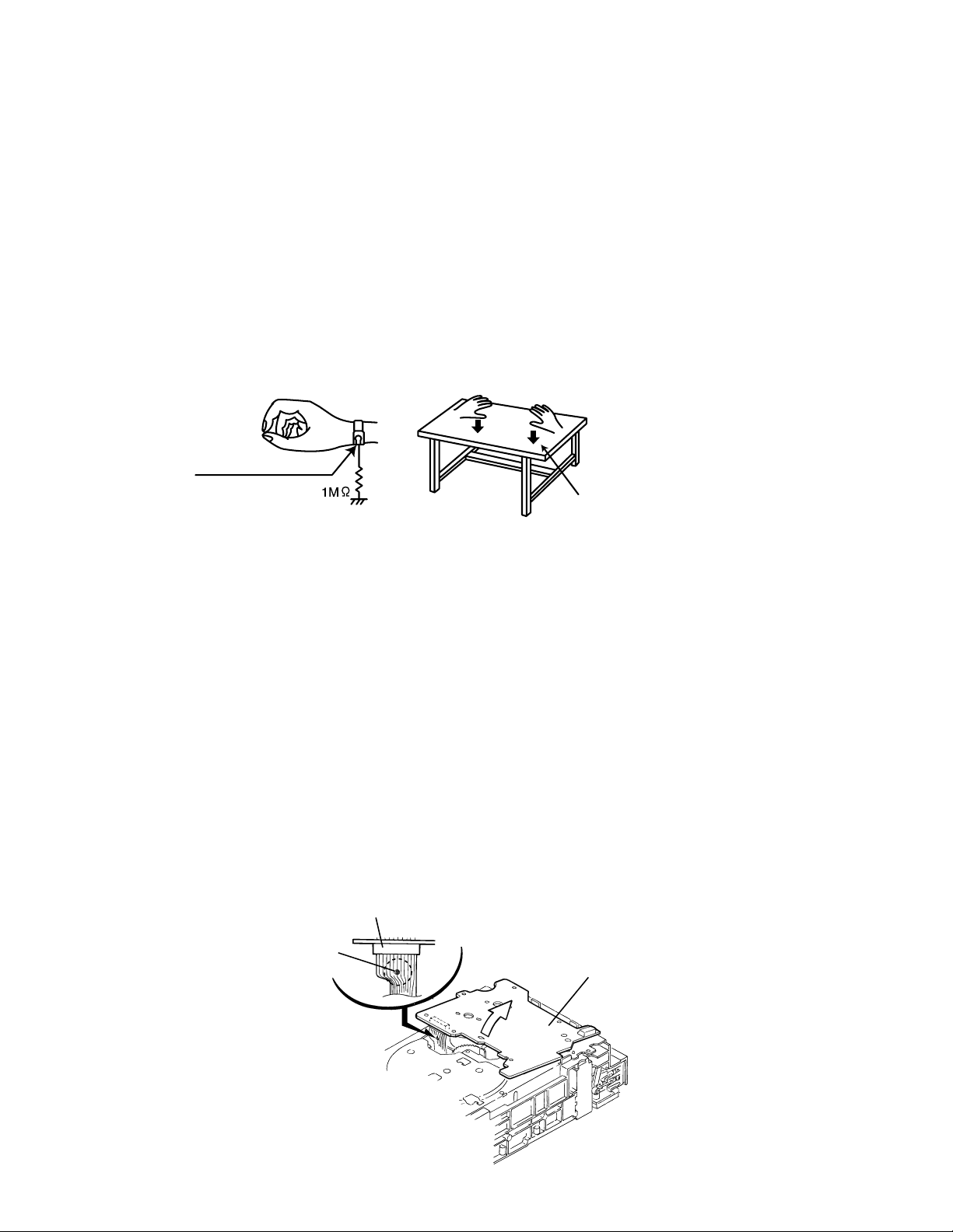
1.1.1. Ground the workbench
1. Ground the workbench by laying conductive material (such as a conductive sheet) or an iron plate over
it before placing the traverse unit (optical pickup) on it.
1.1.2. Ground yourself
1. Use an anti-static wrist strap to release any static electricity built up in your body.
(caption)
Anti-static wrist strap
Conductive material
(conductive sheet) or iron plate
1.1.3. Handling the optical pickup
1. In order to maintain quality during transport and before installation, both sides of the laser diode on the
replacement optical pickup are shorted. After replacement, return the shorted parts to their original condition.
(Refer to the text.)
2. Do not use a tester to check the condition of the laser diode in the optical pickup. The tester's internal power
source can easily destroy the laser diode.
1.2. Handling the traverse unit (optical pickup)
1. Do not subject the traverse unit (optical pickup) to strong shocks, as it is a sensitive, complex unit.
2. Cut off the shorted part of the flexible cable using nippers, etc. after replacing the optical pickup. For specific
details, refer to the replacement procedure in the text. Remove the anti-static pin when replacing the traverse
unit. Be careful not to take too long a time when attaching it to the connector.
3. Handle the flexible cable carefully as it may break when subjected to strong force.
4. It is not possible to adjust the semi-fixed resistor that adjusts the laser power. Do not turn it
CN601
Solder part
Servo control board
1-2
Page 3

Adjustment method
Measurement instruments required
for adjustment
1. Low frequency oscillator,
This oscillator should have a capacity to output 0dBs
to 600ohm at an oscillation frequency of 50Hz-20kHz.
2. Attenuator impedance : 600ohm
3. Electronic voltmeter
4. Frequency counter
5. Test disc
: CTS-1000(12cm),CRG-1211(8cm)
Measurement conditions
Power supply voltage
AC120V(60Hz)
Measurement
output terminal : Speaker out
: Dummy load 6ohm
NX-CDR7
Radio input signal
AM modulation frequency : 400Hz
Modulation factor : 30%
FM modulation frequency : 400Hz
Frequency displacement : 22.5kHz
Frequency Range
AM 531kHz~1710kHz
FM 87.5MHz~108MHz
Standard measurement positions of volume
and switch
Power : Standby (Light STANDBY Indicator)
Sub woofer VOL. : Minimum
Sound mode : OFF
Main VOL. : Minimum
Traverse mecha set position : Disc 1
Precautions for measurement
1. Apply 30pF and 33kohm to the IF sweeper output
side and 0.082 F and 100kohm in series to
the sweeper input side.
2. The IF sweeper output level should be made as
low as possible within the adjustable range.
3. Since the IF sweeper is a fixed device, there is
no need to adjust this sweeper.
4. Since a ceramic oscillator is used, there is no need
to perform any MPX adjustment.
5. Since a fixed coil is used, there is no need to adjust
the FM tracking.
6. The input and output earth systems are separated.
In case of simultaneously measuring the voltage
in both of the input and output systems with an
electronic voltmeter for two channels, therefore,
the earth should be connected particularly.
7. In the case of BTL connection amplifier, the minus
terminal of speaker is not for earthing. Therefore,
be sure not to connect any other earth terminal
to this terminal. This system is of an OTL system.
1-3
Page 4

NX-CDR7
Confirm method of operation
Chec
k mode
1.All lighting FL display
2.Reducing time operation of clock
3.Service menu 1
4.SErvice menu 2
<How to set on TEST MODE 1>
Plug AC power cord into AC outret while pressing "REC MUTE" and "B.SKIP" button simultaneously.
<Setting method of TEST MODE 2>
Plug AC power cord into AC outret while pressing "REC MUTE" and "F.SKIP" button simultaneously.
<How to release TEST MODE>
Unplug AC power cord from AC outret.
TEST MODE 1
TEST MODE 2
Service menu 1
Set TEST MODE 1(As described above)
Press F.SKIP + POWER key simultaneously =
Set STOP mode on 3CD or CDR
Each time MENU is pressed and mode will be changed as below
R E A D I D C O D E
E N G S E T U P
Note:This indication is nothing to with service
3 C D F C A D J
Note:This indication is nothing to with service
3 C D T R A D J
Note:This indication is nothing to with service
POWER ON
The FL display will be
TEST
.
Press SET key
Maker code Type code Unit code
MODE2
The power on will turn on and the FL display
will go back to normal
The following will be displayed for 5sec
J V C C A 0 1 0 8 9 2 3 1
1-4
S Y S T E M A G I N G 1
S Y S T E M A G I N G 2
Durig aging operation,press anykey to stop.
Durig aging operation,press "STOP" key or "ERROR" to stop then the following will be displayed.
Error unit error code Last time operation How many times aging
CD or CDR Hexadecimal 2 dedits COPY or PLAY or ERASE
R E A D V E R S I O N
Press SET key
Press SET key
1 1 1 1 3 3 2 7 8
Main CPU
The following functions will be repeated
1 Disc dubbing(copy)
CDR playing untill read out area
CDR disc erasing
1 Disc dubbing(copy)
CDR disc erasing
4 dedits decimal
CDR CPU
3CD CPU
Page 5

Service menu 2
Set TEST MODE 2(Refer to page 1-4)
NX-CDR7
E
T
T
S
MODE2
Press F.SKIP + POWER key simultaneously =
Set STOP mode on 3CD or CDR
Each time MENU is pressed and mode will be changed as below
Unfinaiize area playing on dsic
P M A S K I P P L A Y
T R A C K U N S K I P
1.Press Set key
U N S K I P X X
2.The head SKIP track is indicated by blink on DISC
of a CD-RW unit at a display and the beginning.
The power on will turn on and the FL display
will go back to normal.
Setting the unfinalize area playing on dsic(CDR)
Press Set key
Writing the unskip information
(Writing the skip track on PMA area of disc)
P M A S K I P O N
Changing by F.SKIP
and B.SKIP key
P M A S K I P O F F
D C E R A S E
3.Choose a SKIP track by the F. SKIP/B.SKIP key.
4.It cannot choose except a SKIP track.
The following indication is given when there is no SKIP track.
N O S K I P T R
A display is displayed for 3 seconds and it escapes
from menu mode.
The SET key is pushed after SKIP track selection and
UNSKIP track information is recorded on PMA area of
disc.
W R I T E U N S K I P
The same character display as the time of writing is performed at
the time of record.
It considers as STOP mode by completion.
Turn off the power supply when writing in SKIP track information,
after track elimination is completed then power off.
Set key on
DISC ERASE operation is started and it eliminates
from the inner side of the circumference PCA area
in DISC.
After the elimination,a DISC is ejected.
2sec lighting, 0.5sec
blink displays.
2sec lighting, 0.5sec
blink displays.
1-5
Page 6

NX-CDR7R
VICTOR COMPANY OF JAPAN, LIMITED
AUDIO & COMUNICATION BUSINESS DIVISION
PERSONAL & MOBILE NETWORK BUSINESS UNIT. 10-1,1chome,Ohwatari-machi,Maebashi-city,371-8543,Japan
(No.20912B)
Printed in Japan
200111(V)
 Loading...