

Page 1
SERVICE MANUAL
LCD INTEGRATED DIGITAL TELEVISION
YA50920074SERVICE MANUAL
LT-26A80SU, LT-26A80ZU, LT-26DA8BJ,
LT-26DA8SJ, LT-26DA8SU, LT-26DA8ZU,
LT-26DT8ZJ, LT-32A80SU, LT-32A80ZU,
LT-32DA8BJ, LT-32DA8SJ, LT-32DA8SU,
LT-32DA8ZU, LT-32DT8ZJ
BASIC CHASSIS
FT3
[A80 series]
COPYRIGHT © 2007 Victor Company of Japan, Limited
1 PRECAUTION. . . . . . . . . . . . . . . . . . . . . . . . . . . . . . . . . . . . . . . . . . . . . . . . . . . . . . . . . . . . . . . . . . . . . . . . . 1-4
2 SPECIFIC SERVICE INSTRUCTIONS . . . . . . . . . . . . . . . . . . . . . . . . . . . . . . . . . . . . . . . . . . . . . . . . . . . . . . 1-8
3 DISASSEMBLY . . . . . . . . . . . . . . . . . . . . . . . . . . . . . . . . . . . . . . . . . . . . . . . . . . . . . . . . . . . . . . . . . . . . . . 1-13
4 ADJUSTMENT . . . . . . . . . . . . . . . . . . . . . . . . . . . . . . . . . . . . . . . . . . . . . . . . . . . . . . . . . . . . . . . . . . . . . . . 1-18
5 TROUBLESHOOTING . . . . . . . . . . . . . . . . . . . . . . . . . . . . . . . . . . . . . . . . . . . . . . . . . . . . . . . . . . . . . . . . . 1-22
[DA8 series]
[DT8 series]
TABLE OF CONTENTS
COPYRIGHT © 2007 Victor Company of Japan, Limited
No.YA509
2007/4
Page 2
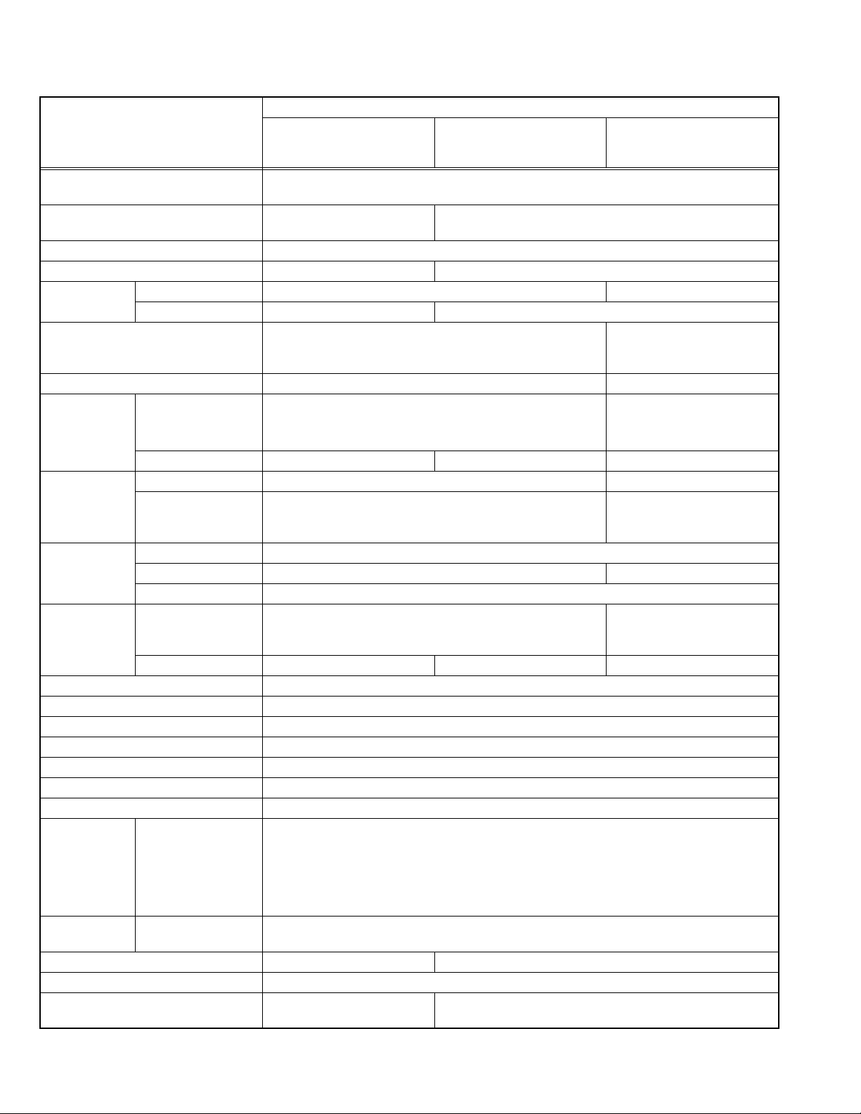
SPECIFICATION
Contents
Items
Dimensions ( W × H × D ) 67.2 cm × 51.9 cm × 23.0 cm [Included stand]
67.2 cm × 47.1 cm × 10.7 cm [TV only]
Mass 11.2 kg [Included stand]
10.4 kg [TV only]
Power Input AC220V - AC240 V, 50 Hz
Power Consumption 105 W (Standby: 1.6 W) 116 W (Standby: 1.6 W)
TV RF System Analog CCIR (B/G, I, D/K, L) CCIR (I)
Digital --- DVB-T
Colour System PAL,
SECAM,
NTSC 3.58/4.43 [EXT only]
Stereo System NICAM (B/G, I, D/K, L), A2 (B/G, D/K) NICAM (I)
Receiving
Frequency
Intermediate
Frequency
Colour Sub
Carrier
Frequency
Teletext System Analog FLOF (Fastext level 2.5)
LCD panel 26V-inch wide aspect (16 : 9)
Screen Size Diagonal : 66 cm (H: 57.6 cm × V: 32.4 cm)
Display Pixels Horizontal : 1366 dots × Vertical : 768 dots (W-XGA)
Audio Power Output 6 W + 6 W
Speaker 5.0 cm × 12.0 cm, oval type × 2
Aerial terminal (VHF/UHF) 75 Ω unbalanced, coaxial
EXT-1 / EXT-2 (Input / Output) 21-pin Euro connector (SCART socket ) × 2
EXT-3 (Input) Component Video
625p / 525p / 625i / 525i
EXT-4 / EXT-5
(HDMI Input)
Digital Audio Optical Output --- Digital SPDIF × 1
Headphone 3.5 mm stereo mini jack × 1
Remote Control Unit RM-C1508
Design & specifications are subject to change without notice.
Analog VHF: 47MHz - 470MHz
UHF: 470 MHz - 862 MHz
CATV: 116MHz - 172MHz / 220MHz - 469MHz
Digital --- UHF:
VIF 38.9MHz (B/G, I, D/K, L) 38.9MHz (I)
SIF 33.4MHz (5.5MHz :B/G)
32.9MHz (6.0MHz :I)
32.4MHz (6.5MHz :D/K)
PAL 4.43MHz
SECAM 4.40625MHz / 4.25MHz ---
NTSC 3.58MHz / 4.43MHz
TOP
WST(World Standard system)
Digital --- EBU TEXT MHEG 5 UK profile
RCA pin jack × 3
750p / 1125i
Video/Audio HDMI 2-row 19pin connector × 2
Y : 1 V (p-p) (Sync signal: ±0.35V(p-p), 3-value sync.), 75Ω
Pb/Pr : ±0.35V(p-p), 75 Ω
Y : 1 V (p-p), Positive (Negative sync.), 75 Ω
Cb/Cr : 0.7V(p-p), 75 Ω
Audio
500 mV(rms) (-4dBs), high impedance, RCA pin jack × 2
(Digital-input terminal is not compatible with picture signals of personal computer)
(AA/R6 dry cell battery × 2)
LT-26A80SU
LT-26A80ZU
LT-26DA8SU
LT-26DA8ZU
11.6 kg [Included stand]
10.8 kg [TV only]
177.5 MHz - 858 MHz
RM-C1821
(AA/R6 dry cell battery × 2)
PAL,
NTSC 3.58/4.43 [EXT only]
UHF: 470 MHz - 862 MHz
UHF:
474 MHz - 850 MHz
32.9MHz (6.0MHz :I)
FLOF (Fastext level 2.5)
WST(World Standard system)
LT-26DA8BJ
LT-26DA8SJ
LT-26DT8ZJ
1-2 (No.YA509)
Page 3
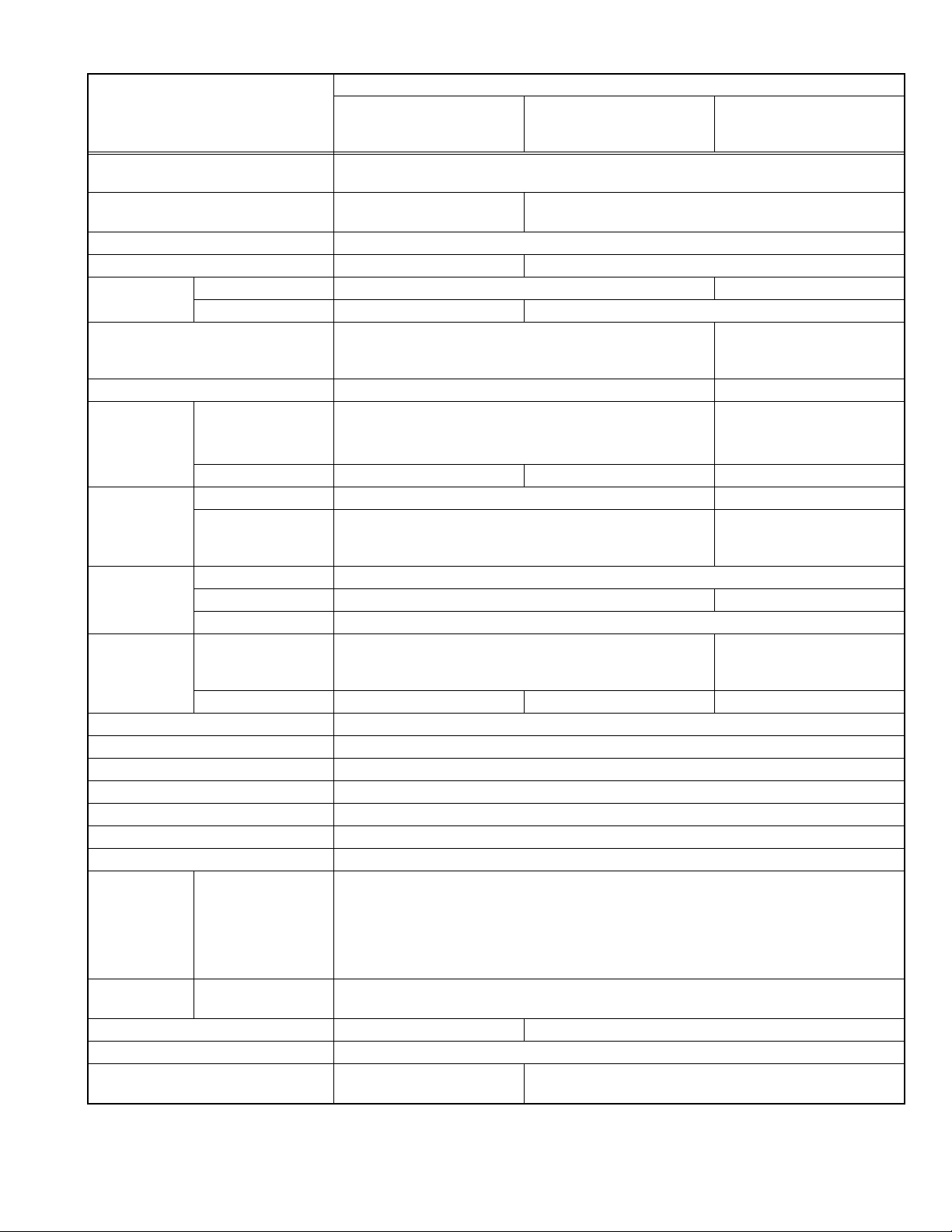
Contents
Items
Dimensions ( W × H × D ) 80.0 cm × 59.1 cm × 23.0 cm [Included stand]
80.0 cm × 54.5 cm × 9.9 cm [TV only]
Mass 13.8 kg [Included stand]
13.0 kg [TV only]
Power Input AC220V - AC240 V, 50 Hz
Power Consumption 114 W (Standby: 1.6 W) 125 W (Standby: 1.6 W)
TV RF System Analog CCIR (B/G, I, D/K, L) CCIR (I)
Digital --- DVB-T
Colour System PAL
SECAM
NTSC 3.58/4.43 [EXT only]
Stereo System NICAM (B/G, I, D/K, L), A2 (B/G, D/K) NICAM (I)
Receiving
Frequency
Intermediate
Frequency
Colour Sub
Carrier
Frequency
Teletext System Analog FLOF (Fastext level 2.5)
LCD panel 32V-inch wide aspect (16 : 9)
Screen Size Diagonal : 80 cm (H: 69.7 cm × V: 39.2 cm)
Display Pixels Horizontal : 1366 dots × Vertical : 768 dots (W-XGA)
Audio Power Output 6 W + 6 W
Speaker 5.0 cm × 12.0 cm, oval type × 2
Aerial terminal (VHF/UHF) 75 Ω unbalanced, coaxial
EXT-1 / EXT-2 (Input / Output) 21-pin Euro connector (SCART socket ) × 2
EXT-3 (Input) Component Video
625p / 525p / 625i / 525i
EXT-4 / EXT-5
(HDMI Input)
Digital Audio Optical Output --- Digital SPDIF × 1
Headphone 3.5 mm stereo mini jack × 1
Remote Control Unit RM-C1508
Analog VHF: 47MHz - 470MHz
UHF: 470 MHz - 862 MHz
CATV: 116MHz - 172MHz / 220MHz - 469MHz
Digital --- UHF:
VIF 38.9MHz (B/G, I, D/K, L) 38.9MHz (I)
SIF 33.4MHz (5.5MHz :B/G)
32.9MHz (6.0MHz :I)
32.4MHz (6.5MHz :D/K)
PAL 4.43MHz
SECAM 4.40625MHz / 4.25MHz ---
NTSC 3.58MHz / 4.43MHz
TOP
WST(World Standard system)
Digital --- EBU TEXT MHEG 5 UK profile
RCA pin jack × 3
750p / 1125i
Video/Audio HDMI 2-row 19pin connector × 2
Y : 1 V (p-p) (Sync signal: ±0.35V(p-p), 3-value sync.), 75Ω
Pb/Pr : ±0.35V(p-p), 75 Ω
Y : 1 V (p-p), Positive (Negative sync.), 75 Ω
Cb/Cr : 0.7V(p-p), 75 Ω
Audio
500 mV(rms) (-4dBs), high impedance, RCA pin jack × 2
(Digital-input terminal is not compatible with picture signals of personal computer)
(AA/R6 dry cell battery × 2)
LT-32A80SU
LT-32A80ZU
LT-32DA8SU
LT-32DA8ZU
14.3 kg [Included stand]
13.5 kg [TV only]
177.5 MHz - 858 MHz
RM-C1821
(AA/R6 dry cell battery × 2)
PAL
NTSC 3.58/4.43 [EXT only]
UHF: 470 MHz - 862 MHz
UHF:
474 MHz - 850 MHz
32.9MHz (6.0MHz :I)
FLOF (Fastext level 2.5)
WST(World Standard system)
LT-32DA8BJ
LT-32DA8SJ
LT-32DT8ZJ
Design & specifications are subject to change without notice.
(No.YA509)1-3
Page 4
SECTION 1
PRECAUTION
1.1 SAFETY PRECAUTIONS [EXCEPT FOR UK]
(1) The design of this product contains special hardware,
many circuits and components specially for safety
purposes. For continued protection, no changes should be
made to the original design unless authorized in writing by
the manufacturer. Replacement parts must be identical to
those used in the original circuits. Service should be
performed by qualified personnel only.
(2) Alterations of the design or circuitry of the products should
not be made. Any design alterations or additions will void
the manufacturer's warranty and will further relieve the
manufacturer of responsibility for personal injury or
property damage resulting therefrom.
(3) Many electrical and mechanical parts in the products have
special safety-related characteristics. These
characteristics are often not evident from visual inspection
nor can the protection afforded by them necessarily be
obtained by using replacement components rated for
higher voltage, wattage, etc. Replacement parts which
have these special safety characteristics are identified in
the parts list of Service manual. Electrical components
having such features are identified by shading on the
schematics and by ( ) on the parts list in Service
manual. The use of a substitute replacement which does
not have the same safety characteristics as the
recommended replacement part shown in the parts list of
Service manual may cause shock, fire, or other hazards.
(4) Don't short between the LIVE side ground and
ISOLATED (NEUTRAL) side ground or EARTH side
ground when repairing.
Some model's power circuit is partly different in the GND.
The difference of the GND is shown by the LIVE : ( ) side
GND, the ISOLATED (NEUTRAL) : ( ) side GND and
EARTH : ( ) side GND.
Don't short between the LIVE side GND and ISOLATED
(NEUTRAL) side GND or EARTH side GND and never
measure the LIVE side GND and ISOLATED (NEUTRAL)
side GND or EARTH side GND at the same time with a
measuring apparatus (oscilloscope etc.). If above note will
not be kept, a fuse or any parts will be broken.
(5) When service is required, observe the original lead dress.
Extra precaution should be given to assure correct lead
dress in the high voltage circuit area. Where a short circuit
has occurred, those components that indicate evidence of
overheating should be replaced. Always use the
manufacturer's replacement components.
(6) Isolation Check (Safety for Electrical Shock Hazard)
After re-assembling the product, always perform an
isolation check on the exposed metal parts of the cabinet
(antenna terminals, video/audio input and output terminals,
Control knobs, metal cabinet, screw heads, earphone jack,
control shafts, etc.) to be sure the product is safe to operate
without danger of electrical shock.
a) Dielectric Strength Test
The isolation between the AC primary circuit and all metal
parts exposed to the user, particularly any exposed metal
part having a return path to the chassis should withstand a
voltage of 3000V AC (r.m.s.) for a period of one second. (.
. . . Withstand a voltage of 1100V AC (r.m.s.) to an
appliance rated up to 120V, and 3000V AC (r.m.s.) to an
appliance rated 200V or more, for a period of one second.)
This method of test requires a test equipment not generally
found in the service trade.
b) Leakage Current Check
Plug the AC line cord directly into the AC outlet (do not use
a line isolation transformer during this check.). Using a
"Leakage Current Tester", measure the leakage current
from each exposed metal part of the cabinet, particularly
any exposed metal part having a return path to the chassis,
to a known good earth ground (water pipe, etc.). Any
leakage current must not exceed 0.5mA AC (r.m.s.).
However, in tropical area, this must not exceed 0.2mA AC
(r.m.s.).
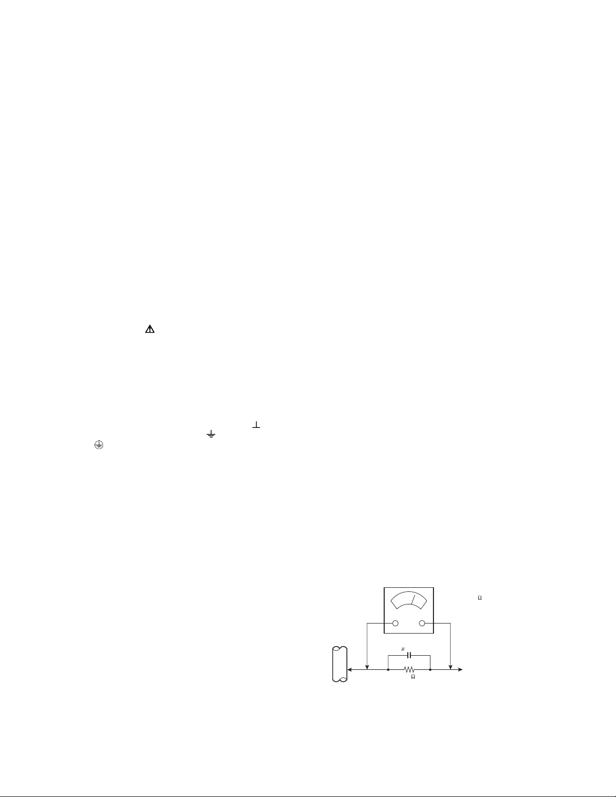
Alternate Check Method
Plug the AC line cord directly into the AC outlet (do not
use a line isolation transformer during this check.). Use
an AC voltmeter having 1000Ω per volt or more
sensitivity in the following manner. Connect a 1500Ω
10W resistor paralleled by a 0.15µF AC-type capacitor
between an exposed metal part and a known good earth
ground (water pipe, etc.). Measure the AC voltage
across the resistor with the AC voltmeter. Move the
resistor connection to each exposed metal part,
particularly any exposed metal part having a return path
to the chassis, and measure the AC voltage across the
resistor. Now, reverse the plug in the AC outlet and
repeat each measurement. Any voltage measured must
not exceed 0.75V AC (r.m.s.). This corresponds to
0.5mA AC (r.m.s.).
However, in tropical area, this must not exceed 0.3V AC
(r.m.s.). This corresponds to 0.2mA AC (r.m.s.).
AC VOLTMETER
(HAVING 1000 /V,
OR MORE SENSITIVITY)
1-4 (No.YA509)
0.15 F AC-TYPE
GOOD EARTH GROUND
1500 10W
PLACE THIS PROBE
ON EACH EXPOSED
ME TAL PAR T
Page 5

1.2 SAFETY PRECAUTIONS [FOR UK]
(1) The design of this product contains special hardware and many circuits and components specially for safety purposes. For
continued protection, no changes should be made to the original design unless authorized in writing by the manufacturer.
Replacement parts must be identical to those used in the original circuits. Service should be performed by qualified personnel
only.
(2) Alterations of the design or circuitry of the product should not be made. Any design alterations or additions will void the
manufacturer's warranty and will further relieve the manufacturer of responsibility for personal injury or property damage
resulting therefrom.
(3) Many electrical and mechanical parts in the product have special safety-related characteristics. These characteristics are often
not evident from visual inspection nor can the protection afforded by them necessary be obtained by using replacement
components rated for higher voltage, wattage, etc. Replacement parts which have these special safety characteristics are
identified in the Parts List of Service Manual. Electrical components having such features are identified by shading on the
schematics and by ( ) on the Parts List in the Service Manual. The use of a substitute replacement which does not have the
same safety characteristics as the recommended replacement part shown in the Parts List of Service Manual may cause shock,
fire, or other hazards.
(4) The leads in the products are routed and dressed with ties, clamps, tubing’s, barriers and the like to be separated from live parts,
high temperature parts, moving parts and / or sharp edges for the prevention of electric shock and fire hazard. When service is
required, the original lead routing and dress should be observed, and it should be confirmed that they have been returned to
normal, after re-assembling.
WARNING
(1) The equipment has been designed and manufactured to meet international safety standards.
(2) It is the legal responsibility of the repairer to ensure that these safety standards are maintained.
(3) Repairs must be made in accordance with the relevant safety standards.
(4) It is essential that safety critical components are replaced by approved parts.
(5) If mains voltage selector is provided, check setting for local voltage.
(No.YA509)1-5
Page 6

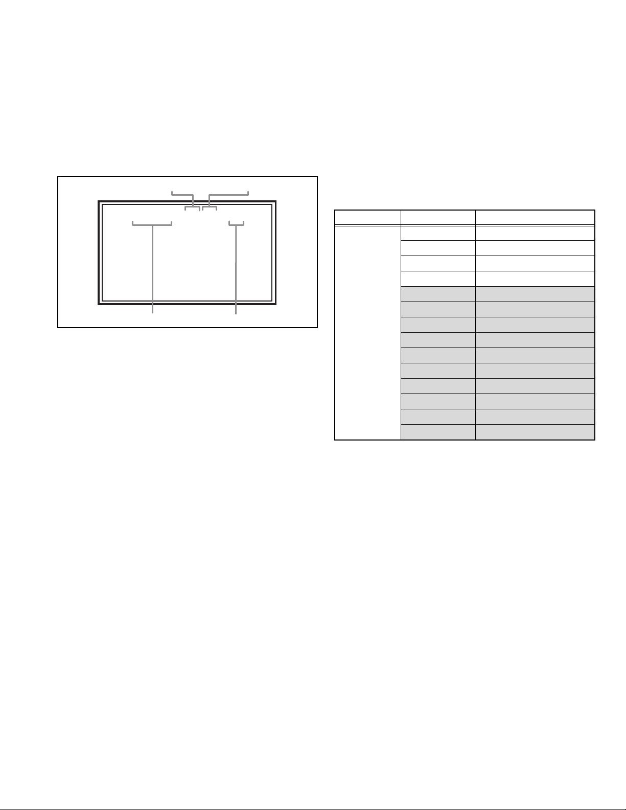
1.3 INSTALLATION
1.3.1 HEAT DISSIPATION
If the heat dissipation vent behind this unit is blocked, cooling
efficiency may deteriorate and temperature inside the unit will
rise. The temperature sensor that protects the unit will be
activated when internal temperature exceeds the pre-determined
level and power will be turned off automatically.Therefore,
please make sure pay attention not to block the heat dissipation
vent as well as the ventilation outlet behind the unit and ensure
that there is room for ventilation around it.
VENTILATION HOLE
*Diagram differs from actual appearance.
1.3.3 INSTALLATION REQUIREMENTS
To ensure safety in an emergency such as an earthquake, and
to prevent accidents, ensure that measures are taken to prevent
the TV dropping or falling over.
It fixes in a band.
TV STAND
*Diagram differs from actual appearance.
1.3.4 NOTES ON HANDLING
When taking the unit out of a packing case, do not grasp the
upper part of the unit. If you take the unit out while grasping the
upper part, the LCD PANEL may be damaged because of a
pressure. Instead of grasping the upper part, put your hands on
the lower backside or sides of the unit.
1.3.2 INSTALLATION REQUIREMENTS
Ensure that the minimal distance is maintained, as specified
below, between the unit with and the surrounding walls, as well
as the floor etc.Install the unit on stable flooring or stands.Take
precautionary measures to prevent the unit from tipping in order
to protect against accidents and earthquakes.
150 mm
*Diagram differs from actual appearance.
200 mm
POWER
150 mm
200 mm
50 mm
1-6 (No.YA509)
Page 7

1.4 HANDLING LCD PANEL
1.4.1 PRECAUTIONS FOR TRANSPORTATION
When transporting the unit, pressure exerted on the internal LCD
panel due to improper handling (such as tossing and dropping)
may cause damages even when the unit is carefully packed. To
prevent accidents from occurring during transportation, pay
careful attention before delivery, such as through explaining the
handling instructions to transporters.
Ensure that the following requirements are met during
transportation, as the LCD panel of this unit is made of glass and
therefore fragile:
(1) USE A SPECIAL PACKING CASE FOR THE LCD PANEL
When transporting the LCD panel of the unit, use a special
packing case (packing materials). A special packing case
is used when a LCD panel is supplied as a service spare
part.
(2) ATTACH PROTECTION SHEET TO THE FRONT
Since the front (display part) of the panel is vulnerable,
attach the protection sheet to the front of the LCD panel
before transportation. Protection sheet is used when a LCD
panel is supplied as a service spare part.
(3) AVOID VIBRATIONS AND IMPACTS
The unit may be broken if it is toppled sideways even when
properly packed. Continuous vibration may shift the gap of
the panel, and the unit may not be able to display images
properly. Ensure that the unit is carried by at least 2
persons and pay careful attention not to exert any vibration
or impact on it.
(4) DO NOT PLACE EQUIPMENT HORIZONTALLY
Ensure that it is placed upright and not horizontally during
transportation and storage as the LCD panel is very
vulnerable to lateral impacts and may break. During
transportation, ensure that the unit is loaded along the
traveling direction of the vehicle, and avoid stacking them
on one another. For storage, ensure that they are stacked
in 2 layers or less even when placed upright.
1.4.2 OPTICAL FILTER (ON THE FRONT OF THE LCD PANEL)
(1) Avoid placing the unit under direct sunlight over a
prolonged period of time. This may cause the optical filter
to deteriorate in quality and COLOUR.
(2) Clean the filter surface by wiping it softly and lightly with a
soft and lightly fuzz cloth (such as outing flannel).
(3) Do not use solvents such as benzene or thinner to wipe the
filter surface. This may cause the filter to deteriorate in
quality or the coating on the surface to come off. When
cleaning the filter, usually use the neutral detergent diluted
with water. When cleaning the dirty filter, use water-diluted
ethanol.
(4) Since the filter surface is fragile, do not scratch or hit it with
hard materials. Be careful enough not to touch the front
surface, especially when taking the unit out of the packing
case or during transportation.
1.4.3 PRECAUTIONS FOR REPLACEMENT OF EXTERIOR
PARTS
Take note of the following when replacing exterior parts (REAR
COVER, FRONT PANEL, etc.):
(1) Do not exert pressure on the front of the LCD panel (filter
surface). It may cause irregular COLOUR.
(2) Pay careful attention not to scratch or stain the front of the
LCD panel (filter surface) with hands.
(3) When replacing exterior parts, the front (LCD panel) should
be placed facing downward. Place a mat, etc. underneath
to avoid causing scratches to the front (filter surface).
(No.YA509)1-7
Page 8

SECTION 2
SERVICE MENU
1.ADJUST
2.SELF_CHECK
3.I2C STOP
*** SHIPPING STRAT ***
SPECIFIC SERVICE INSTRUCTIONS
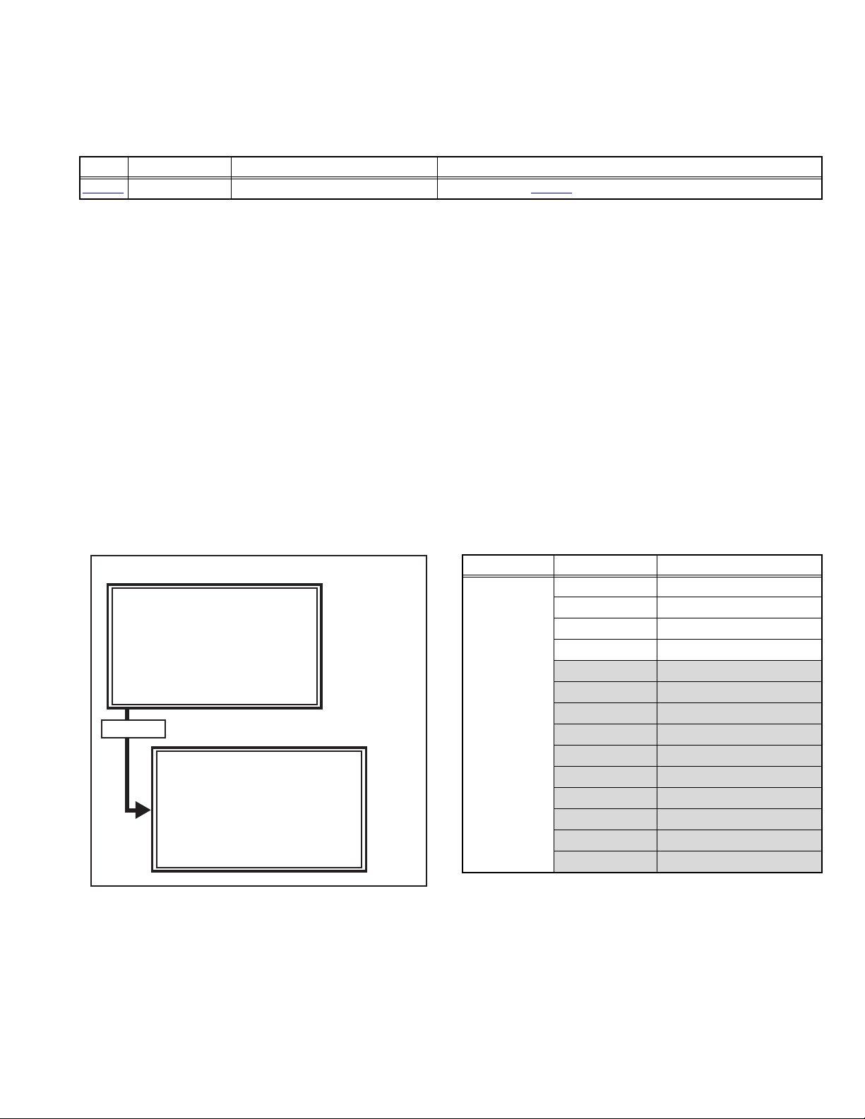
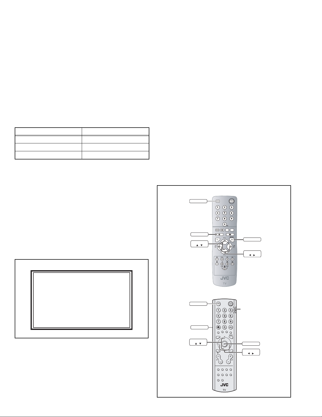
2.1 SYSTEM SETTEING
Be sure to perform the following operation at the end of the
procedure.
(1) Press the [INFORMATION] key and [MUTING] key
simultaneously, then enter the SERVICE MODE(Fig.2-1).
(2) When the Main Menu is displayed, press [9].
(3) The screen shown in Fig.2-2 is displayed, and the
SYSTEM SETTING starts.
NOTE:
When the SYSTEM SETTING is performed, all settings are
reset to the factory setting. Perform the setting again.
SERVICE MENU SCREEN
SERVICE MENU
1.ADJUST
2.SELF_CHECK
3.I2C STOP
Fig. 2-1
Press [9] key
2.2 FEATURES
DIGITAL TUNER [DA8/DT8 series only]
This TV can receive both DVB-T (Digital terrestrial broadcasting)
and Analogue terrestrial broadcasting.
HDMI INPUT
By connecting a HDMI compatible device, high definition
pictures can be displayed on your TV in their digital form.
MOVIE THEATRE
This function displays a cinema film picture more smoothly and
naturally on the screen.
DIGITAL VNR
This function cuts down the amount of noise in the original
picture.
3D Cinema Sound
You can enjoy sounds with a wider ambience.
SHIPPING SCREEN
PR List Empty
*** SHIPPING STRAT ***
Fig. 2-2
2.3 MAIN DIFFERENCE LIST
Item
Paint Color Silver Black Silver Black Silver × Black Silver Black
Digital Tuner NO ← YES ←← ← ←
Teletext (Analog) TOP/FLOF ←←←FLOF ←←
Teletext (Digital) NO ← EBU TEXT ←
Broadcasting System B/G, D/K, I, L ←←← I ←←
RF System PAL/SECAM ←←←PAL ←←
Stereo System A2/NICAM ←←←NICAM ←←
Power cord Plug Type
Indoor ANT Power Supply NO ← YES ←← ← ←
Digital Audio Optical Output NO ← YES ←← ← ←
Remote Control Unit RM-C1508-1C ← RM-C1821-1C ←← ← ←
LT-26A80SU
LT-32A80SU
EU Type (2 Pins)
LT-26A80ZU
LT-32A80ZU
←←←
LT-26DA8SU
LT-32DA8SU
LT-26DA8ZU
LT-32DA8ZU
LT-26DA8BJ
LT-32DA8BJ
MHEG 5 UK profile
UK Type (3 Pins)
LT-26DA8SJ
LT-32DA8SJ
←←
←←
LT-26DT8ZJ
LT-32DT8ZJ
1-8 (No.YA509)
Page 9
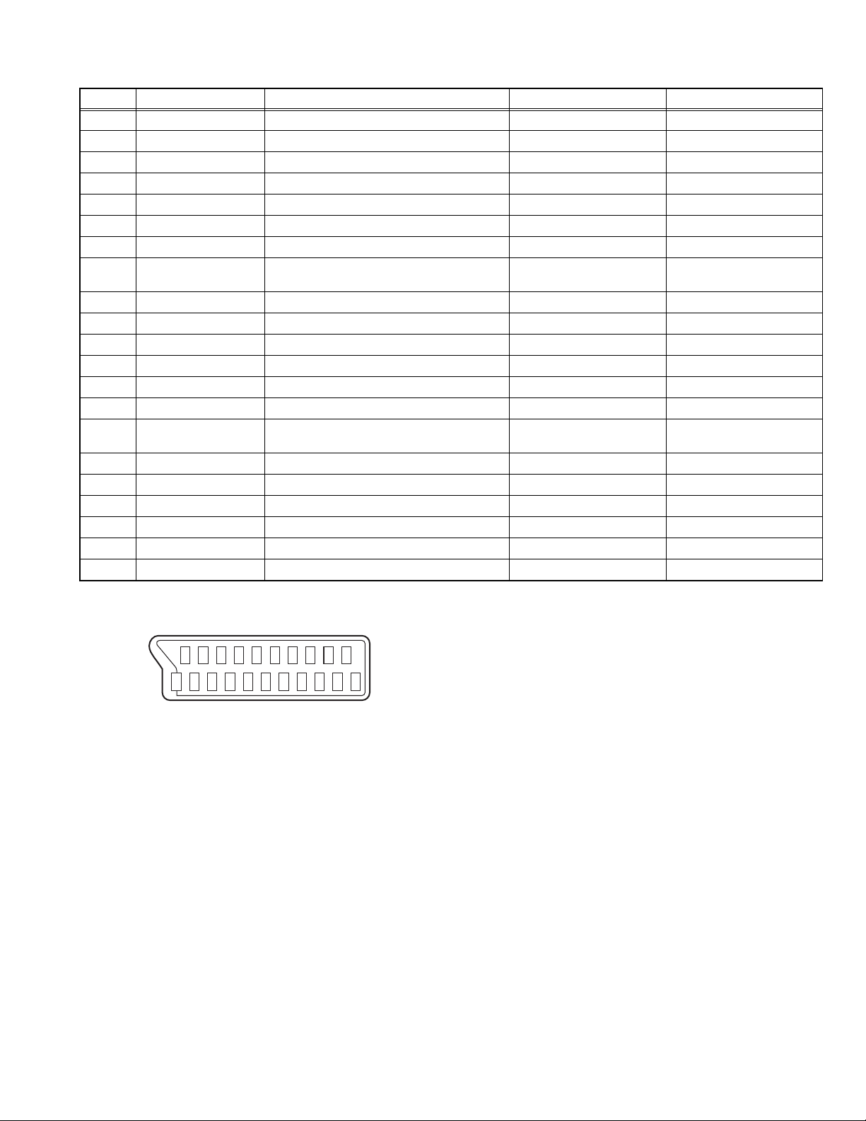
2.4 21-PIN EURO CONNECTOR (SCART) : EXT-1 / EXT-2
Pin No. Signal designation Matching value EXT-1 EXT-2
1 AUDIO R output 500mV(rms) (Nominal), Low impedance Used (TV OUT) Used (LINE OUT)
2 AUDIO R input 500mV(rms) (Nominal), High impedance Used (R1) Used (R2)
3 AUDIO L output 500mV(rms) (Nominal), Low impedance Used (TV OUT) Used (LINE OUT)
4 AUDIO GND Used Used
5 GND (B) Used Used
6 AUDIO L input 500mV(rms) (Nominal), High impedance Used (L1) Used (L2)
7 B input 700mV
8 FUNCTION SW
(SLOW SW)
Low : 0V-3V
High : 8V-12V, High impedance
, 75Ω Used Used
(B-W)
Used Used
9 GND (G) Used Used
10 SCL / T-V LINK Not used Used (SCL2 / TV-LINK)
11 G input 700mV
, 75Ω Used Used
(B-W)
12 SDA Not used Used (SDA2)
13 GND (R) Used Used
14 GND (YS) Used Not used
15 R / C input R : 700mV
C : 300mV
(B-W)
(P-P)
, 75Ω
, 75Ω
Used (R) Used (C2/R)
16 Ys input (FAST SW) Low : 0V-0.4V, High : 1V-3V, 75Ω Used Used
17 GND (VIDEO output) Used Used
18 GND (VIDEO input) Used Used
19 VIDEO output 1V
20 VIDEO / Y input 1V
(Negative sync), 75Ω Used (TV OUT) Used (LINE OUT)
(P-P)
(Negative sync), 75Ω Used Used
(P-P)
21 COMMON GND Used Used
(P-P= Peak to Peak, B-W= Blanking to white peak)
[Pin assignment]
20 18 16 14 12 10 8 6 4 2
21 19 17 15 13 11 9 7 5 3 1
(No.YA509)1-9
Page 10
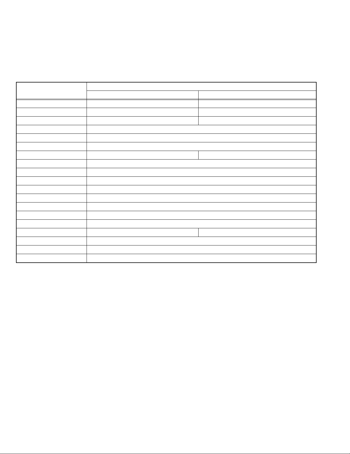
2.5 TECHNICAL INFORMATION
2.5.1 LCD PANEL
This unit uses the flat type panel LCD (Liquid Crystal Display) panel that occupies as little space as possible, instead of the
conventional CRT (Cathode Ray Tube), as a display unit.
Since the unit has the two polarizing filter that are at right angles to each other, the unit adopts "normally black" mode, where light
does not pass through the polarizing filter and the screen is black when no voltage is applied to the liquid crystals.
2.5.1.1 SPECIFICATIONS
The following table shows the specifications of this unit.
Item
Maximum dimensions ( W × H × D )
26V LCD PANEL UNIT 32V LCD PANEL UNIT
62.6 cm × 37.3 cm × 4.8 cm 76.0 cm × 45.0 cm × 4.5 cm
Specifications
Weight 4.5 kg 6.5 kg
Effective screen size Diagonal: 660 mm (H: 576 mm × V: 324 mm) Diagonal: 800 mm (H: 697 mm × V: 392 mm)
Aspect ratio 16 : 9
Drive device / system a-Si-TFT active matrix system
Resolution Horizontally 1366 × Vertically 768 × RGB <W-XGA> 3147264 dots in total
Pixel pitch (pixel size) Horizontally: 0.4215 mm, Vertically: 0.4215 mm Horizontally: 0.51075 mm, Vertically: 0.51075 mm
Displayed colour 16777216 colours 256 colours for R G and B
Brightness 500cd/m
2
Contrast ratio 1200 : 1
Response time (Tr) less than 8 ms
View angle (Horizontally) 176°
View angle (Vertically) 176°
Surface polarizer Anti-Glare type Low reflective coat
Colour filter Vertical stripe
Backlight Cold cathode fluorescent lamp × 6 (U-TYPE) Cold cathode fluorescent lamp × 12
Power supply voltage in LCD 12 V
Power supply voltage in inverter
24 V
Panel interface system LVDS (Low Voltage Differential Signaling)
2.5.1.2 PIXEL FAULT
There are three pixel faults - bright fault , dark fault and flicker fault - that are respectively defined as follows.
BRIGHT FAULT
In this pixel fault, a cell that should not light originally is lighting on and off.
For checking this pixel fault, input ALL BLACK SCREEN and find out the cell that is lighting on and off.
DARK FAULT
In this pixel fault, a cell that should light originally is not lighting or lighting with the brightness twice as brighter as originally lighting.
For checking this pixel fault, input 100% of each R/G/B colour and find out the cell that is not lighting.
FLICKER FAULT
In the pixel fault, a cell that should light originally or not light originally is flashing on and off.
For checking this pixel fault, input ALL BLACK SCREEN signal or 100% of each RGB colour and find out the cell that is flashing on
and off.
1-10 (No.YA509)
Page 11
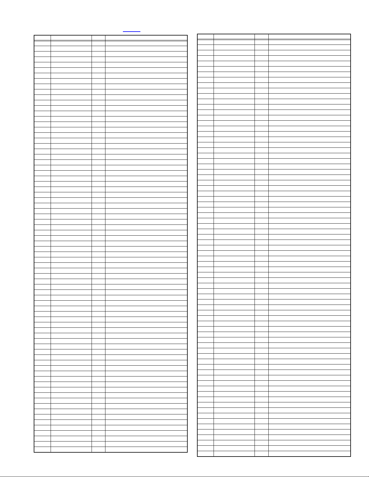
2.5.2 MAIN CPU PIN FUNCTION [IC7001
: MAIN PWB]
Pin Pin name I/O Function
1 T-V LINK_OUT O Data output for T-V LINK
2POWER_G I
3 PROTECTOR I
Not used : Low power voltage detection [NG = H]
Power abnormality detection [Emergent = H]
4 TCLK I Clock for JTAG interface
5 TDO O Data output for JTAG interface
6 TDI I Data input for JTAG interface
7 TMS I Control signal for JTAG interface
8 RESETQ I CPU reset [Reset = L]
9 E3_R I Audio input for EXT-3
10 E3_L I Audio input for EXT-3
11 DIN/D_R I Audio input for digital tuner/HDMI
12 DIN/D_L I Audio input for digital tuner/HDMI
13 E1_R I Audio input for EXT-1
14 E1_L I Audio input for EXT-1
15 E2_R I Audio input for EXT-2
16 E2_L I Audio input for EXT-2
17 VREFAU I Reference voltage setting
18 VSUP8.0AU I 8V power supply
19 GNDA - GND
20 SGND - GND
21 R2_OUT O Audio output for EXT-2
22 L2_OUT O Audio output for EXT-2
23 R_OUT O Audio output for EXT-1
24 L_OUT O Audio output for EXT-1
25 HEADPHONE_R O Audio output for headphone
26 HEADPHONE_L O Audio output for headphone
27 SPEAKER_R O Audio output for speaker
28 SPEAKER_L O Audio output for speaker
29 SUBWOOFER O Not used
30 VREFSIF I Reference voltage setting
31 SIF_IN+ I SIF for VHF/UHF tuner
32 SIF_IN- I SIF for VHF/UHF tuner
33 VSUP5.0 I 5V power supply
34 GNDA - GND
35 GND3.3DIG - GND
36 VSUP3.3DIG I 3.3V power supply
37 SPDIF_OUT O Not used
38 I2S_DA_IN I Not used
39 I2S_CL - Not used
40 I2S_WS - Not used
41 I2S_DEL_OUT O Not used
42 I2S_DEL_IN I Not used
43 I2S_DEL_CL - Not used
44 I2S_DEL_WS - Not used
45 VSUP3.3RAM I 3.3V power supply
46 GND3.3RAM - GND
47 VD_DV1 I V sync for HDMI
48 DE_DV1 I Data enable for HDMI
49 CLK_DV1 I Clock for HDMI
50 DV1_R7 I Pr input for HDMI
51 DV1_R6 I Pr input for HDMI
52 DV1_R5 I Pr input for HDMI
53 DV1_R4 I Pr input for HDMI
54 DV1_R3 I Pr input for HDMI
55 DV1_R2 I Pr input for HDMI
56 DV1_R1 I Pr input for HDMI
57 DV1_R0 I Pr input for HDMI
58 DV1_Y7 I Y input for HDMI
59 DV1_Y6 I Y input for HDMI
60 DV1_Y5 I Y input for HDMI
61 DV1_Y4 I Y input for HDMI
62 DV1_Y3 I Y input for HDMI
63 DV1_Y2 I Y input for HDMI
64 DV1_Y1 I Y input for HDMI
65 DV1_Y0 I Y input for HDMI
66 DV1_B7 I Pb input for HDMI
67 DV1_B6 I Pb input for HDMI
68 DV1_B5 I Pb input for HDMI
69 DV1_B4 I Pb input for HDMI
70 DV1_B3 I Pb input for HDMI
71 DV1_B2 I Pb input for HDMI
72 DV1_B1 I Pb input for HDMI
73 DV1_B0 I Pb input for HDMI
74 GND3.3DRI - GND
75 VSUP3.3DRI I 3.3V power supply
76 GND3.3COM - GND
Pin Pin name I/O Function
77 VSUP3.3COM I 3.3V power supply
78 X'TALIN I 20.25MHz oscillation for CPU system clock
79 X'TALOUT O 20.25MHz oscillation for CPU system clock
80 CLKOUT O Not used
81 VSO O Not used
82 HSO O Not used
83 SCL1 O Clock for I
84 SDA1 I/O Data for I
2
C bus (for HDMI)
2
C bus (for HDMI)
85 GND3.3FL - GND
86 VSUP3.3FL I 3.3V power supply
87 AFC1 I AFT voltage for VHF/UHF tuner
88 DIN_PHOTO I For digital input protection
89 A_MU O
90 PFC_POW O
Speaker/headphone output muting [Muting = H]
Not used : Power on/off control for PFC [ON = L]
91 DIN_INT I Interrupt request for HDMI
92 LCD_POW O Power on/off control for LCD drive [ON = L]
93 OSDV I Not used
94 OSDH I Not used
95 GND3.3IO1 - GND
96 VSUP3.3IO1 I 3.3V power supply
97 OSDCLK I Not used
98 OSDFSW I Not used
99 MAIN_POW O
Power on/off control for main power [ON = L]
100 IDTV_IRQ O Interrupt request for digital tuner
101 RXD I Data communication for digital tuner
102 TXD O Data communication for digital tuner
103 OSDB1 O Not used
104 OSDB0 O Not used
105 LB_POW O
Power on/off control for low bias line [ON = L]
106 REMOCON I Remote control sensor input
107 OSDG1 O Not used
108 OSDG0 O Not used
109 SDA0 I/O Data for I
110 SCL0 O Clock for I
2
C bus (for E2PROM)
2
C bus (for E2PROM)
111 OSDR1 O Not used
112 OSDR0 O Not used
113 GND3.3IO1 - GND
114 VSUP3.3IO1 I 3.3V power supply
115 DIN_HOTP O
Hotplug error detection for HDMI connector-1 [Error = L]
116 DIN_RST O Reset for HDMI [Reset = L]
117 MB_RES O Not used : Reset for MaxxBass [Reset = L]
118 PCS3 O Not used
119 POW_LED O POWER LED(green) lighting [ON = L]
120 DINHOTP2 O
Hotplug error detection for HDMI connector-2 [Error = L]
121 PCLK2 O Not used
122 PCLK1 O Not used
123 GND1.8DIG - GND
124 VSUP1.8DIG I 1.8V power supply
125 DBO1_0 O Not used
126 DBO1_1 O Not used
127 VSUP3.3LVDS I 3.3V power supply
128 LVDS_A3+ O LVDS data output for LCD panel
129 LVDS_A3- O LVDS data output for LCD panel
130 GND3.3LVDS - GND
131 LVDS_ACLK+ O LVDS clock output for LCD panel
132 LVDS_ACLK- O LVDS clock output for LCD panel
133 VSUP3.3LVDS I 3.3V power supply
134 LVDS_A2+ O LVDS data output for LCD panel
135 LVDS_A2- O LVDS data output for LCD panel
136 GND3.3LVDS - GND
137 LVDS_A1+ O LVDS data output for LCD panel
138 LVDS_A1- O LVDS data output for LCD panel
139 VSUP3.3LVDS I 3.3V power supply
140 LVDS_A0+ O LVDS data output for LCD panel
141 LVDS_A0- O LVDS data output for LCD panel
142 VSUP1.8LVDS I 1.8V power supply
143 REXT O Not used
144 GND1.8LVDS - GND
145 DGO1_8 O Not used
146 DGO1_9 O Not used
147 GND3.3LVDS - GND
148 DRO1_1 O Not used
149 LVDS_BCLK- O Not used
150 VSUP3.3LVDS I 3.3V power supply
151 DRO1_2 O Not used
152 DRO1_3 O Not used
153 GND3.3LVDS - GND
(No.YA509)1-11
Page 12
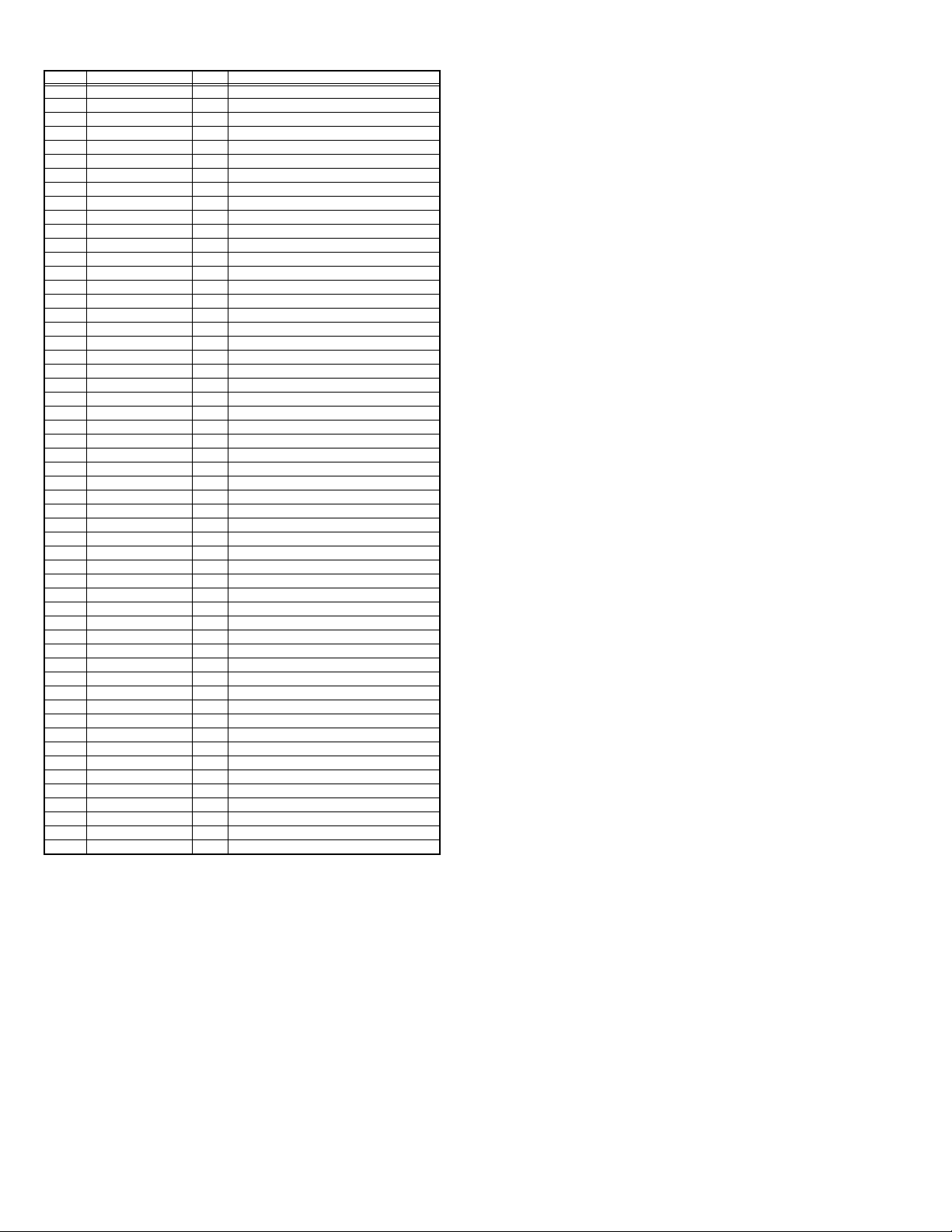
Pin Pin name I/O Function
154 DRO1_5 O Not used
155 DRO1_6 O Not used
156 VSUP3.3LVDS I 3.3V power supply
157 DRO1_8 O Not used
158 DRO1_9 O Not used
159 AGC I RF AGC voltage for VHF/UHF tuner
160 KEY1 I
161 SLOW1 I EXT-1 SLOW detection
162 SLOW2 I EXT-2 SLOW detection
163 GND3.3DAC - GND
164 VSUP3.3DAC I 3.3V power supply
165 DC_DIM O DC dimming control for back-light inverter
166 PWM_DIM O
167 DTV_SW O
168 SUB_MUTE O Audio output muting [Muting = L]
169 VSUP1.8FE I 1.8V power supply
170 VSUP3.3FE I 3.3V power supply
171 HD_DV1 I H sync for HDMI
172 SC_B1 I B input for EXT-1
173 SC_G1 I G input for EXT-1
174 SC_R1 I R input for EXT-1
175 SC_YS2 I Ys input for EXT-2
176 E3_PB I Pb input for EXT-3
177 E3_Y I Y input for EXT-3
178 E3_PR I Pr input for EXT-3
179 SC_B2 I B input for EXT-2
180 SC_G2 I G input for EXT-2
181 SC_R2/C I R/C input for EXT-2
182 D_BY I Pb input for digital tuner
183 SC_YS1 I Ys input for EXT-1
184 D_Y I Y input for digital tuner
185 VSUP1.8FE I 1.8V power supply
186 GNDA - GND
187 D_RY I Pr input for digital tuner
188 D_CV I Video input for digital tuner
189 E1_CV I Video input for EXT-1
190 E2_CV/Y I Video/Y input for EXT-2
191 TV_CV I Video input for VHF/UHF tuner
192 VSUP3.3VO I 3.3V power supply
193 VOUT3 O Not used
194 VOUT2 O Not used
195 V2_OUT O Video output for EXT-2
196 GND3.3IO3 - GND
197 VSUP3.3IO3 I 3.3V power supply
198 656I0 I Not used
199 656I1 I Not used
200 656I2 I Not used
201 656I3 I Not used
202 656I4 I Not used
203 656I5 I Not used
204 656I6 I Not used
205 656I7 I Not used
206 656CLKI I Not used
207 656CLKO O Not used
208 TV_LINK_IN I Data input from T-V LINK
Key scan for side control (POWER/CH+/CH-/MENU)
PWM dimming control for back-light inverter
Audio output select for EXT-2 [Digital tuner = H]
1-12 (No.YA509)
Page 13

SECTION 3
DISASSEMBLY
3.1 DISASSEMBLY PROCEDURE
• Be sure to perform the SYSTEM SETTEING, at the end of the procedure.
• Make sure that the power cord is disconnected from the outlet.
• Pay special attention not to break or damage the parts.
• Make sure that there is no bent or stain on the connectors before inserting, and firmly insert the connectors.
REFERENCE:
When removing each board, remove the connector if necessary. The operation is easier if you write down the connection points
(connector numbers) of the connector. For connection of each board, refer to the "WIRING DIAGRAM" of the Standard Circuit
Diagram.
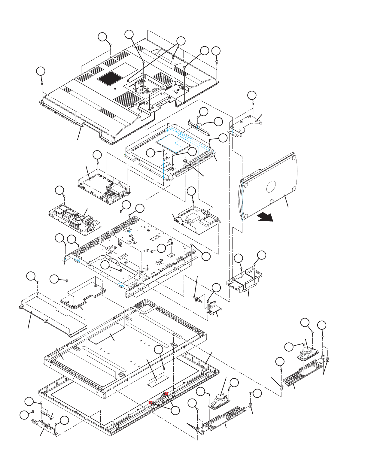
3.1.1 REMOVING THE REAR COVER (Fig.3-1)
(1) Remove the 6 screws [A], the 2 screws [B], the 5 screws
[C] and the 5 screws [D].
(2) Remove the REAR COVER.
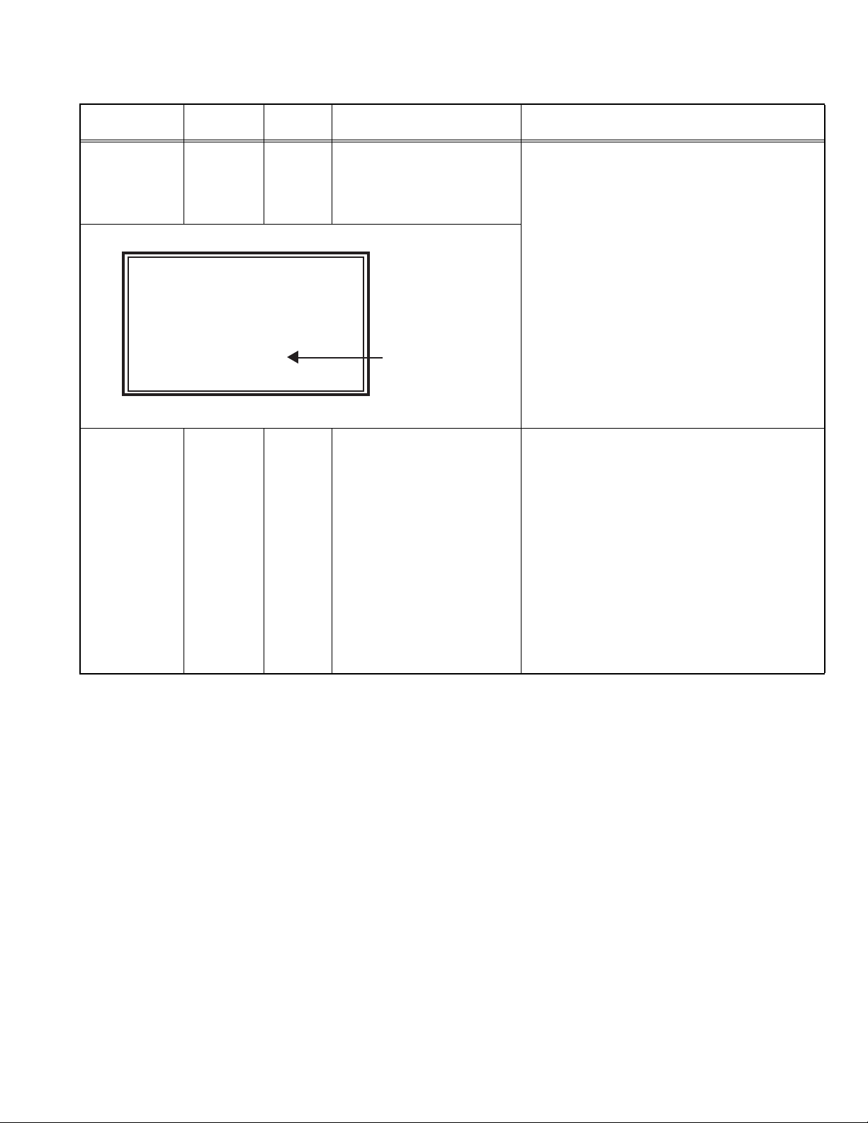
3.1.2 REMOVING THE STAND ASS’Y (Fig.3-1)
(1) Remove the 4 screws [E].
(2) Remove the STAND ASS’Y in the direction of the arrow.
3.1.3 REMOVING THE POWER PWB (Fig.3-1)
• Remove the REAR COVER.
(1) Remove the 1 screw [F].
(2) Remove the POWER CORD HOLDER.
(3) Remove the POWER CORD.
(4) Remove the 5 screws [G].
(5) Remove the POWER PWB.
3.1.4 REMOVING THE MAIN PWB (Fig.3-1)
• Remove the REAR COVER.
(1) Remove the 1 screw [H] [DA8/DT8 series only].
(2) Remove the DIGITAL BASE [DA8/DT8 series only].
(3) Remove the 2 screws [I] [DA8/DT8 series only].
(4) Remove the 7 screws [J], the 2 screws [K], 1 screw [L] and 1
nut.
(5) Remove the SHIELD COVER.
(6) Remove the 6 screws [M].
(7) Remove the MAIN PWB.
CAUTION :
Make sure to perform the "SYSTEM SETTEING", when MAIN
PWB is replaced.
3.1.5 REMOVING THE DIGITAL TUNER UNIT [DA8/DT8
series only] (Fig.3-1)
• Remove the REAR COVER.
• Remove the DIGITAL BASE.
• Remove the SHIELD COVER.
(1) Remove the 5 screws [N].
(2) Remove the DIGITAL TUNER UNIT.
3.1.6 REMOVING THE SW PWB (Fig.3-1)
• Remove the REAR COVER.
(1) Remove the 2 screws [O].
(2) Remove the SW PWB.
(3) Remove the 2 screws [P].
(4) Remove the CONTROL KNOB.
3.1.7 REMOVING THE LED PWB (Fig.3-1)
• Remove the REAR COVER.
• Remove the STAND ASS’Y.
(1) Remove the 2 screw [Q].
(2) Remove the STAND BASE COVER.
(3) Remove the 1 screw [R] and 2 screws [S].
(4) Remove the STAND BASE.
(5) Remove the 2 screws [T] and 2 hooks [a].
(6) Remove the LED PWB.
3.1.8 REMOVING THE SPEAKER HOLDER AND SPEAKER
(Fig.3-1)
• Remove the REAR COVER.
• Remove the STAND ASS’Y.
• Remove the STAND BASE COVER.
• Remove the STAND BASE.
(1) Remove the 4 screws [U].
(2) Remove the SPEKAER.
(3) Remove the 3 screws [V].
(4) Remove the SPEKAER HOLDER.
(5) Follow the same steps when removing the other hand
SPEAKER HOLDER and SPEAKER.
3.1.9 REMOVING THE LCD PANEL UNIT (Fig.3-1)
• Remove the REAR COVER.
• Remove the STAND ASS’Y.
• Remove the STAND BASE COVER.
• Remove the STAND BASE.
• Remove the POWER CORD HOLDER.
• Remove the SPEKAER HOLDER.
(1) Remove the 6 screws [W].
(2) Remove the 4 screws [X].
(3) Remove the MAIN BASE.
(4) Remove the LCD PANEL UNIT from the FRONT PANEL.
3.1.10 REMOVING THE CONTROL PWB (Fig.3-1)
• Remove the REAR COVER.
• Remove the STAND ASS’Y.
• Remove the STAND BASE COVER.
• Remove the STAND BASE.
• Remove the MIAN BASE.
(1) Remove the 4 screws [Y].
(2) Remove the CONTROL PWB COVER.
(3) Remove the CONTROL PWB.
3.1.11 REMOVING THE INVERTER PWB (Fig.3-1)
• Remove the REAR COVER.
(1) Remove the 6 screws [Z].
(2) Remove the INVERTER PWB COVER.
(3) Remove the INVERTER PWB.
(No.YA509)1-13
Page 14
B
D
C
D
A
A
Q
DIGITAL
BASE
H
STAND BASE COVER
I
J
REAR COVER
L
SHIELD
COVER
NUT
N
STAND ASS'Y
G
W
MAIN PWB
POWER PWB
X
M
W
K
DIGITAL
TUNER UNIT
X
[DA8/DT8 series]
X
W
MAIN BASE
Z
Y
X
POWER CORD
R
S
F
INVERTER PWB
COVER
INVERTER PWB
O
P
CONTROL KNOB
SW PWB
1-14 (No.YA509)
STAND BASE
CONTROL PWB
COVER
CONTROL
PWB
T
LED PWB
POWER CORD
HOLDER
FRONT PANEL
SPEAKER
U
U
V
V
SPEAKER
U
U
SPACER
V
SPACER
SPEAKER HOLDER
V
a
P
SPACER
SPEAKER HOLDER
SPACER
The illustration is LT-32DA8 series
Fig.3-1
Page 15
3.2 MEMORY IC REPLACEMENT
SERVICE MENU
1.ADJUST
2.SELF_CHECK
3.I2C STOP
ADJUST
AUTO
FUL
1.SC ADJ
14
SC DEV:+ 0
- + OK:STORE i=EXIT
• This model uses the memory IC.
• This memory IC stores data for proper operation of the video and drive circuits.
• When replacing, be sure to use an IC containing this (initial value) data.
3.2.1 MEMORY IC TABLE
Simbol Number of pins Mounting PWB Main content of data
IC7003
8-pin MAIN PWB Setting value of IC7001(MAIN CPU) is memorized.
3.2.2 MEMORY IC REPLACEMENT PROCEDURE
1. Power off
Switch off the power and disconnect the power plug from the AC outlet.
2. Replace the memory IC
Be sure to use the memory IC written with the initial setting values.
3. Power on
Connect the power plug to the AC outlet and switch on the power.
4. Receiving channel setting
Refer to the OPERATING INSTRUCTIONS and set the receive channels (Channels Preset) as described.
5. User setting
Check the user setting items according to the given in page later. Where these do not agree, refer to the OPERATING
INSTRUCTIONS and set the items as described.
6. SERVICE MODE setting
Verify what to set in the SERVICE MODE, and set whatever is necessary (Fig.3-2). Refer to the SERVICE ADJUSTMENT for
setting.
3.2.3 SERVICE MODE SETTING
SERVICE MODE SCREEN
SERVICE MODE SCREEN
SERVICE MENU
1.ADJUST
2.SELF_CHECK
3.I2C STOP
Press [1] key
1. ADJUST
ADJUST
AUTO
1.SC ADJ
- + OK:STORE i=EXIT
FUL
14
SC DEV:+ 0
Fig.3-2
SETTING ITEM
Setting mode Setting items Settings
1.ADJUST 1.SC ADJ. Adjust
2.R DRIVE Adjust
3.G DRIVE Adjust
4.B DRIVE Adjust
5.CUTOFF R Fixed [Do not adjust]
6.CUTOFF G Fixed [Do not adjust]
7.CUTOFF B Fixed [Do not adjust]
8.COLOUR Fixed [Do not adjust]
9.HUE Fixed [Do not adjust]
10.CONTRAST Fixed [Do not adjust]
11.BRIGHT Fixed [Do not adjust]
12.SHARP Fixed [Do not adjust]
13.DC EXTMD Fixed [Do not adjust]
14.PWM EXTMD Fixed [Do not adjust]
(No.YA509)1-15
Page 16
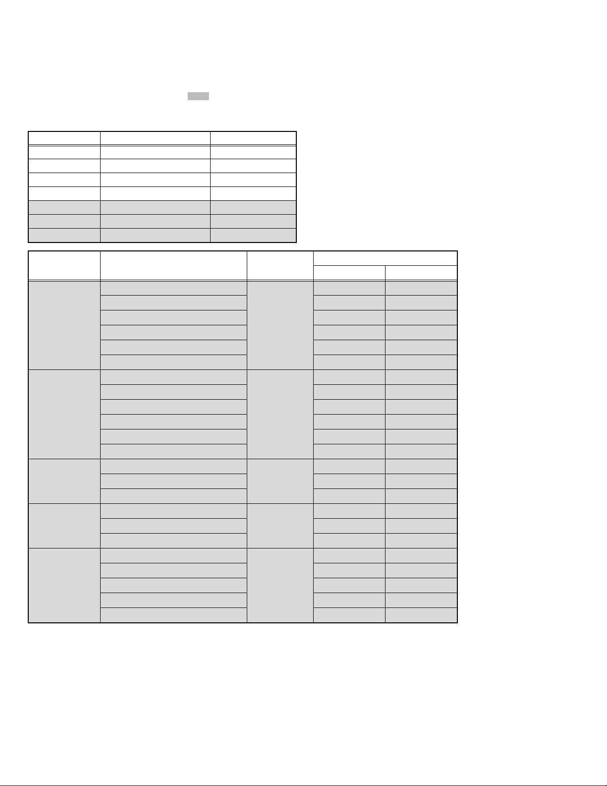
3.2.4 SETTINGS OF FACTORY SHIPMENT
3.2.4.1 BUTTON OPERATION 3.2.4.2 REMOTE CONTROL DIRECT OPERATION
Setting item Setting position
POWER Off
CHANNEL PR1
VOLUME 10
TV/AV TV
3.2.4.3 REMOTE CONTROL MENU OPERATION
(1) PICTURE
Setting item Setting position
PICTURE MODE BRIGHT
COLOUR TEMP. COOL
FEATURES
DIGITAL VNR ON
Digi Pure ON
MOVIE THEATRE OFF
COLOUR SYSTEM TV Depends on PR/CH
EXT AUTO
4:3 AUTO ASPECT PANORAMIC
(2) SOUND
Setting item Setting position
STEREO / I•II Stereo sound
BASS Centre
TREBLE Centre
BALANCE Centre
HYPER SOUND OFF
3D CINEMA SOUND
SORRUND MID
BASS BOOST MID
(4) FEATURES
Setting item Setting position
SLEEP TIMER OFF
CHILD LOCK ID NO.0000, All CH off
BLUE BACK ON
FAVOURITE SETTING Blank
APPEARANCE TYPE A
(5) SET UP
Setting item Setting position
AUTO PROGRAM TV channel automatically set
EDIT/MANUAL PRESET CH only
LANGUAGE ENGLISH
DECODER (EXT-2) OFF
EXT SETTING EXT-1
ATTENUATOR OFF [DA8/DT8 series only]
HDMI SETTING
HDMI-1 Size AUTO
Audio AUTO
HDMI-2 Size AUTO
CHANNEL PR1
VOLUME 10
ZOOM AUTO
SUB POWER OFF
(6) DTV [DA8/DT8 series only]
[For UK]
Configuration
Audio Language English
Subtitle Language English
Favourite Mode Off
Menu Lock Disable
[For Finland/Germany/Spain/Sweden]
Configuration
Country --- *
Menu Language --- *
Audio Language --- *
Subtitle Language --- *
Teletext Language --- *
EPG Language --- *
Enter PIN Code 0000
Favourite Mode Off
Maturity Rating Off
[For All country]
Setup
Digital Audio Output PCM
Banner Duration 2sec
Receiver Upgrade Auto
Common Interface ---
Antenna Power Off
Setting item Setting position
Setting item Setting position
Setting item Setting position
*It differs according to the language that the user selected.
Setting item Setting position
1-16 (No.YA509)
Page 17
3.3 REPLACEMENT OF CHIP COMPONENT
3.3.1 CAUTIONS
(1) Avoid heating for more than 3 seconds.
(2) Do not rub the electrodes and the resist parts of the pattern.
(3) When removing a chip part, melt the solder adequately.
(4) Do not reuse a chip part after removing it.
3.3.2 SOLDERING IRON
(1) Use a high insulation soldering iron with a thin pointed end of it.
(2) A 30w soldering iron is recommended for easily removing parts.
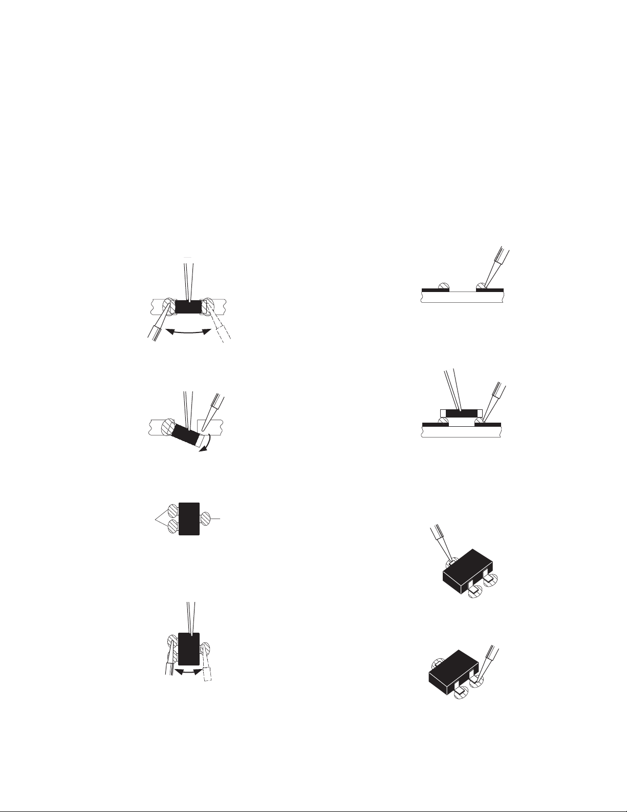
3.3.3 REPLACEMENT STEPS
1. How to remove Chip parts
2. How to install Chip parts
[Resistors, capacitors, etc.]
(1) As shown in the figure, push the part with tweezers and
alternately melt the solder at each end.
(2) Shift with the tweezers and remove the chip part.
[Transistors, diodes, variable resistors, etc.]
(1) Apply extra solder to each lead.
SOLDER
SOLDER
[Resistors, capacitors, etc.]
(1) Apply solder to the pattern as indicated in the figure.
(2) Grasp the chip part with tweezers and place it on the
solder. Then heat and melt the solder at both ends of the
chip part.
[Transistors, diodes, variable resistors, etc.]
(1) Apply solder to the pattern as indicated in the figure.
(2) Grasp the chip part with tweezers and place it on the
solder.
(3) First solder lead A as indicated in the figure.
(2) As shown in the figure, push the part with tweezers and
alternately melt the solder at each lead. Shift and remove
the chip part.
NOTE :
After removing the part, remove remaining solder from the
pattern.
A
B
C
(4) Then solder leads B and C.
A
B
C
(No.YA509)1-17
Page 18
SECTION 4
SERVICE MENU
1.ADJUST
2.SELF_CHECK
3.I2C STOP
ADJUSTMENT
4.1 ADJUSTMENT PREPARATION
(1) This TV is adjusted by using REMOTE CONTROL UNIT.
(2) The adjustment using the REMOTE CONTROL UNIT is made on the basis of the initial setting values. The setting values
which adjust the screen to the optimum condition can be different from the initial setting values.
(3) Make sure that connection is correctly made AC to AC power source.
(4) Turn on the power of the TV and measuring instruments for warming up for at least 30 minutes before starting adjustments.
(5) If the receive or input signal is not specified, use the most appropriate signal for adjustment.
(6) Never touch the parts (such as variable resistors, transformers and condensers) not shown in the adjustment items of this service
adjustment.
4.2 PRESET SETTING BEFORE ADJUSTMENTS
Unless otherwise specified in the adjustment items, preset the
following functions with the REMOTE CONTROL UNIT.
Setting item Settings position
PICTURE MODE STANDARD
PICTURE adjustments Centre
COLOUR TEMP. NORMAL
4.3 MEASURING INSTRUMENT AND FIXTURES
• Signal generator (Pattern generator)[PAL]
• Remote control unit
4.4 ADJUSTMENT ITEMS
VIDEO CIRCUIT
• COLOUR DECODER adjustment
• WHITE BALANCE (HIGH LIGHT) adjustment
4.5 BASIC OPERATION OF SERVICE MODE
4.5.1 HOW TO ENTER THE SERVICE MODE
(1) Press [INFORMATION] key and [MUTING] key on the
remote control unit simultaneously to enter the SERVICE
MODE SCREEN. (Fig.1)
4.5.3 CHANGE AND MEMORY OF SETTING VALUE
SELECTION OF SETTING ITEM
• [FUNCTION /] key.
For scrolling up / down the setting items.
CHANGE OF SETTING VALUE (DATA)
• [FUNCTION /] key.
For scrolling up / down the setting values.
MEMORY OF SETTING VALUE (DATA)
Changed setting value is memorized by pressing [OK] key.
4.5.4 SERVICE MODE SELECT KEY LOCATION
[A80 series] : RM-C1821
MUTING
INFORMATION
FUNCTION
/
OK
FUNCTION
/
SERVICE MODE SCREEN
SERVICE MENU
1.ADJUST
2.SELF_CHECK
3.I2C STOP
Fig.4-1
NOTE:
Before entering the SERVICE MODE, confirm that the setting
of VCR/TV/DVD switch is at the "TV" side. If the switches have
not been properly set, you cannot enter the SERVICE MODE.”
4.5.2 HOW TO EXIT THE SERVICE MODE
Press the [MENU] key to exit the Service mode.
1-18 (No.YA509)
[DA8/DT8 series] : RM-C1508
MUTING
INFORMATION
FUNCTION
/
VCR/TV/DVD
switch
OK
FUNCTION
/
Page 19
4.5.5 ADJUSTMENT MODE
ADJUST AUTO PAL FUL
1.SC ADJ 14
SC DEV:+ 0
- + OK:STORE i=EXIT
This mode is used to adjust the VIDEO CIRCUIT.
4.5.5.1 HOW TO ENTER THE ADJUSTMENT MODE
When the SERVICE MENU SCREEN of SERVICE MODE is displayed, press [1] key to enter the ADJUSTMENT MODE (Fig.2).
NOTE:
• When a number key other than the [1] key is pressed in the SERVICE MODE SCREEN, the other relevant screen may be
displayed.
This is not used in the adjustment procedure. Press the [MENU] key to return to the SERVICE MODE SCREEN.
4.5.5.2 DESCRIPTION OF STATUS DISPLAY
(5) SETTING ITEM NAME
SIGNAL SYSTEM
ZOOM MODE
Setting item name are displayed. The setting item numbers to
be displayed are listed below.
ADJUST AUTO PAL FUL
1.SC ADJ 14
Setting mode Setting items Settings
1.ADJUST 1.SC ADJ. Adjust
2.R DRIVE Adjust
3.G DRIVE Adjust
SC DEV:+ 0
- + OK:STORE i=EXIT
4.B DRIVE Adjust
5.CUTOFF R Fixed [Do not adjust]
6.CUTOFF G Fixed [Do not adjust]
SETTING ITEM
(1) SIGNAL SYSTEM
The signal displayed on the screen is displayed.
PAL : PAL50Hz/60Hz (Composite / S-video)
: DVB-T [Only DA8/DT8 series]
: RGB 576i
SECAM : SECAM
NTSC3.58 : NTSC3.58 / RGB 480i
NTSC4.43 : NTSC4.43
480i : 480i (Component) / HDMI 480i
480p : 480p / HDMI 480p
576i : 576i (Component) / HDMI 576i
SETTING VALUE (DATA)
7.CUTOFF B Fixed [Do not adjust]
8.COLOUR Fixed [Do not adjust]
9.HUE Fixed [Do not adjust]
10.CONTRAST Fixed [Do not adjust]
11.BRIGHT Fixed [Do not adjust]
12.SHARP Fixed [Do not adjust]
13.DC EXTMD Fixed [Do not adjust]
14.PWM EXTMD Fixed [Do not adjust]
(7) SETTING VALUE (DATA)
The SETTING VALUE is displayed.
576p : 576p / HDMI 576p
1080i50 : 1080i 50Hz / HDMI 1080i 50Hz
1080i60 : 1080i 60Hz / HDMI 1080i 60Hz
750p50 : HDMI 750p 50Hz
750p60 : HDMI 750p 60Hz
(2) ZOOM MODE
State of the ZOOM MODE is displayed.
FUL : FULL
PAN : PANORAMIC
16Z : 16:9 ZOOM
SUB : 16:9 ZOOM SUBTITLE
14Z : 14:9 ZOOM
REG : REGULAR
(No.YA509)1-19
Page 20
4.6 INITIAL SETTING VALUES IN THE SERVICE MODE
• Perform fine-tuning based on the "initial values" using the remote control when in the Service mode.
• The "initial values" serve only as an indication rough standard and therefore the values with which optimal display can be achieved
may be different from the default values.
• Never change the values of the items( ) that are not described in ADJUSTMENT PROCEDURE or in the below table as they
are fixed values.
4.6.1 ADJUSTMENT MODE
Item name Variable range Setting value
1. SC ADJ. 0 - 1023 ---
2. R DRIVE 0 - 1023 920
3. G DRIVE 0 - 1023 920
4. B DRIVE 0 - 1023 920
5. CUTOFF R 0 - 1023 0
6. CUTOFF G 0 - 1023 0
7. CUTOFF B 0 - 1023 0
Item name Input signal Variable range
8. COLOUR Other
SECAM 20 20
NTSC 33 33
480i / 480p(Component/HDMI) 41 41
576i / 576p(Component/HDMI) 40 41
720p / 1080i(Component/HDMI) 38 40
9. HUE Other
SECAM 32 32
NTSC 28 30
480i / 480p(Component/HDMI) 32 28
576i / 576p(Component/HDMI) 31 30
720p / 1080i(Component/HDMI) 32 28
10. CONTRAST Other
NTSC 43 43
Component/HDMI 37 37
11. BRIGHT Other
NTSC 263 263
Component/HDMI 268 272
12. SHARP Other
NTSC 0 0
480i / 480p(Component/HDMI) 0 0
576i / 576p(Component/HDMI) +2 +2
720p / 1080i(Component/HDMI) +3 +3
0 - 63
0 - 63
0 - 63
0 - 511
-3 - +3
Setting value
26 inch models 32 inch models
31 30
30 31
43 43
266 259
0 0
1-20 (No.YA509)
Page 21
4.7 ADJUSTMENT PROCEDURE
ADJUST AUTO PAL FUL
1.SC ADJ 14
SC DEV:+ 0
- + OK:STORE i=EXIT
4.7.1 VIDEO CIRCUIT
Item
COLOUR
DECODER
Measuring
instrument
Remote
control unit
Signal
generator
Test point Adjustment part Description
ADJUST AUTO PAL FUL
1.SC ADJ 14
[1.ADJUST]
1.SC ADJ
(1) Receive a PAL colour bar signal.
(2) Select "1.ADJUST" from the SERVICE MODE.
(3) Select <1.SC ADJ>.
(4) Adjust the value of <1.SC ADJ> to set the value
of (A) to 0±3.
NOTE:
The value of <1.SC ADJ> should be adjusted
within 7 - 24.
(5) Press the [OK] key to memoirze the set value.
WHITE
BALANCE
(HIGHLIGHT)
SC DEV:+ 0
- + OK:STORE i=EXIT
Remote
control unit
Signal
generator
[1.ADJUST]
2.R DRIVE
3.G DRIVE
4.B DRIVE
(A)
(1) Receive a PAL 75% all white signal.
(2) Set PICTURE MODE to "STANDARD".
(3) Set ZOOM to "FULL".
(4) Set COLOUR TEMP. to "NORMAL".
(5) Select "1.ADJUST" from the SERVICE MODE.
(6) Adjustment is select 1 item from <2.R DRIVE>,
<3.G DRIVE> and <4.B DRIVE> then select item
fix to "920" Other color shold be less than 920.
NOTE:
Finaly minimam more than 1 item (<2.R
DRIVE>, <3.G DRIVE> or <4.B DRIVE>)
should be "920".
(7) Must check white balance adjustment correctry
with low light to high light.
(8) Press the [OK] key to memoirze the set value.
(No.YA509)1-21
Page 22

SECTION 5
SERVICE MENU
1.ADJUST
2.SELF_CHECK
3.I2C STOP
SELF CHECK
LOB 0
MEM 0 AIO 0
TUN 0 HDM 0
????
i:EXIT
SELF CHECK
SYN OK CDN 02
ADS 30 AIO 2A
PPL 0425 LPF 01BC
VPS = 0000H (---)
PDC 8/30/1 = 0000H
= 0000H
WSS = 0000H
i:EXIT
TROUBLESHOOTING
5.1 SELF CHECK FEATURE
5.1.1 OUTLINE
This unit comes with the "Self check" feature, which checks the
operational state of the circuit and displays/saves it during
failure.Diagnosis is performed when power is turned on, and
information input to the main microcomputer is monitored at all
time.Diagnosis is displayed in 2 ways via screen display and LED
flashes. Failure detection is based on input state of I
the various control lines connected to the main microcomputer.
5.1.2 HOW TO ENTER THE SELF CHECK MODE
Before enter the SELF CHECK MODE, press the [MODE] key to
confirm that "TV" position is indicated. If it is in a wrong position,
the SELF CHECK MODE operation cannot be performed.
(1) Press the [INFORMATION] key and [MUTING] key
simultaneously, then enter the SERVICE MODE.
(2) Press the [2] key SELF CHECK MODE.
(3) Press the [RED] key to enter Page 2 of the SELF CHECK
MODE.
*Use the [GREEN] key to toggle between Page 1 and Page 2.
NOTE:
When a number key other than the [2] key is pressed in the
SERVICE MODE screen, the other relevant screen may be
displayed.
This is not used in the SELF CHECK MODE. Press the
[MENU] key to return to the MAIN MENU SCREEN.
5.1.3 HOW TO EXIT THE SELF CHECK MODE
To Save Failure History:
Turn off the power by unplugging the AC power cord plug when
in the Self check display mode.
To Clear (Reset) Failure History:
Turn off the power by pressing the [POWER] key on the remote
control unit when in the Self check display mode.
2
C bus and
SERVICE MENU SCREEN
SERVICE MENU
1.ADJUST
2.SELF_CHECK
3.I2C STOP
Press [2] key
SELF CHECK MODE SCREEN (Page 1)
SELF CHECK
Failure history
LOB 0
MEM 0 AIO 0
TUN 0 HDM 0
????
Item
i:EXIT
Press [Red] key
Press [Green] key
SELF CHECK MODE SCREEN (Page 2)
5.1.4 FAILURE HISTORY
Failure history can be counted up to 9 times for each item. When
the number exceeds 9, display will remain as 9. Failure history
will be stored in the memory unless it has been deleted.
NOTE:
5.1.5 POINTS TO NOTE WHEN USING THE SELF CHECK
In addition to circuit failures (abnormal operation), the following
cases may also be iagnosed as "Abnormal" and displayed and
counted as "NG".
Diagnosis may be impeded if a large number of items are
displayed as "NG". As such, start Self check check only after 3
seconds in the case of receivers and 5 seconds in the case of
panels upon turning on the power. If recurrences are expected,
ensure to clear (reset) the failure history and record the new
diagnosis reults.
Only SYNC (with/without sync signals) will be neither counted
nor stored.
FEATURE
(1) Temporary defective transmissions across circuits due to
pulse interruptions
(2) Misalignment in the on/off timing of power for I
when turning on/off the main power.
2
C bus (Vcc)
1-22 (No.YA509)
SELF CHECK
Item
SYN OK CDN 02
ADS 30 AIO 2A
PPL 0425 LPF 01BC
VPS = 0000H (---)
PDC 8/30/1 = 0000H
= 0000H
WSS = 0000H
i:EXIT
Fig.5-1
Page 23

5.1.6 DETAILS
Self check is performed for the following items:
<Page 1 of screen>
Detection item Display Detection content
Low bias line short
protection
LOB Confirm the operation of the low bais(5V/12V/
13.5V/14V) protection circuit.
5V: Q9201
[MAIN PWB]
12V: Q9301 [MAIN PWB]
13.5V: Q9505
14V: Q9503
MAIN MEMORY MEM Confirmation of reply of ACK signal which uses
2
C communication.
I
IC7003
[POWER PWB]
[POWER PWB]
[MAIN PWB]
Diagnosis
signal (line)
Detection timing
LB_PRO Detection starts 5 seconds after
the power is turned on. If error
continues between 200 ms the
power is turned off.
SDA If it checks whenever I
communication is performed and
no reply of ACK signal an error
will be counted.
AUDIO AIO Not used ---- ----
RF (ANALOG) TUNER TUN Confirmation of reply of ACK signal which uses
2
C communication.
I
TU1001
[MAIN PWB]
SDA If it checks whenever I
communication is performed and
no reply of ACK signal an error
will be counted.
HDMI HDM Confirmation of reply of ACK signal which uses
2
C communication.
I
SDA If it checks whenever I2C
communication is performed and
no reply of ACK signal an error
will be counted.
<Page 2 of screen> indicates items not used for services as they are for designing.
Detection item Display Detection content Detection timing
SYNC SIGNAL SYN Confirmation of presence of sync signal in
selected video signal.
The selected video input signal is always
checked and if there is the sync signal, it is
displayed as "OK", and if not as "NG".
For designing CDN - -
For designing ADS - -
For designing ADH - -
For designing PPL - -
For designing LPF - -
2
C
2
C
5.1.7 METHOD OF DISPLAY WHEN A RASTER IS NOT OUTPUT
In the state where a raster is not output by breakdown of the set, an error is displayed by blink of the POWER LED.
Type of error POWER LED flash cycle
Low bias line short protection Red turnig on and off at 1 second intervals.
MAIN CPU error detection Red turnig on and off at 2 second intervals.
< Explanation of operation >
If error is detected, the power is turned off. Shortly after the power is turned off, POWER LED will be blinked.
When the protection of low bias line short operates, the power cannot be turned on until the power cord takes out and inserts, after
the power is turned off.
(No.YA509)1-23
Page 24

Victor company of Japan, Limited
Display category 12, 3-chome, Moriya-cho, Kanagawa-ku, Yokohama-city, Kanagawa-prefecture, 221-8528, Japan
(No.YA509)
Printed in Japan
VPT
Page 25

SCHEMATIC DIAGRAMS
LCD INTEGRATED DIGITAL TELEVISION
LT-26A80SU, LT-26A80ZU, LT-26DA8BJ,
LT-26DA8SJ, LT-26DA8SU, LT-26DA8ZU,
LT-26DT8ZJ, LT-32A80SU, LT-32A80ZU,
LT-32DA8BJ, LT-32DA8SJ, LT-32DA8SU,
LT-32DA8ZU, LT-32DT8ZJ
[A80 series]
[DA8 series]
[DT8 series]
CD-ROM No.SML200704
BASIC CHASSIS
FT3
COPYRIGHT © 2007 Victor Company of Japan, Limited.
No.YA509
2007/4
Page 26

LT-26A80SU, LT-26A80ZU, LT-26DA8BJ, LT-26DA8SJ
,
LT-26DA8SU, LT-26DA8ZU, LT-26DT8ZJ, LT-32A80SU,
LT-32A80ZU
LT-32DA8ZU
,
LT-32DA8BJ, LT-32DA8SJ, LT-32DA8SU,
,
LT-32DT8ZJ
STANDARD CIRCUIT DIAGRAM
NOTE ON USING CIRCUIT DIAGRAMS
1.SAFETY
The components identified by the symbol and shading are
critical for safety. For continued safety replace safety ciritical
components only with manufactures recommended parts.
2.SPECIFIED VOLTAGE AND WAVEFORM VALUES
The voltage and waveform values have been measured under the
following conditions.
(1)Input signal : Colour bar signal
(2)Setting positions of
each knob/button and
variable resistor
(3)Internal resistance of tester
(4)Oscilloscope sweeping time
(5)Voltage values
Since the voltage values of signal circuit vary to some extent
according to adjustments, use them as reference values.
: Original setting position
when shipped
: DC 20kΩ/V
: H
: V
: Othters
: All DC voltage values
20µs / div
5ms / div
Sweeping time is
specified
3.INDICATION OF PARTS SYMBOL [EXAMPLE]
In the PW board
: R209
R209
4.INDICATIONS ON THE CIRCUIT DIAGRAM
(1)Resistors
Resistance value
No unit : [Ω]
K
M
Rated allowable power
No indication : 1/16 [W]
Others : As specified
Type
No indication
OMR
MFR
MPR
UNFR
FR
Composition resistor 1/2 [W] is specified as 1/2S or Comp.
(2)Capacitors
Capacitance value
1 or higher : [pF]
less than 1
Withstand voltage
No indication : DC50[V]
Others : DC withstand voltage [V]
AC indicated
Electrolytic Capacitors
47/50[Example]: Capacitance value [µF]/withstand voltage[V]
: [kΩ]
: [MΩ]
: Carbon resistor
: Oxide metal film resistor
: Metal film resistor
: Metal plate resistor
: Uninflammable resistor
: Fusible resistor
: [µF]
: AC withstand voltage [V]
Type
No indication
MM
PP
MPP
MF
TF
BP
TAN
(3)Coils
No unit
Others
(4)Power Supply
Respective voltage values are indicated
(5)Test point
: Test point
(6)Connecting method
(7)Ground symbol
: LIVE side ground
: ISOLATED(NEUTRAL) side ground
: EARTH ground
: DIGITAL ground
5.NOTE FOR REPAIRING SERVICE
This model's power circuit is partly different in the GND. The
difference of the GND is shown by the LIVE : ( ) side GND and the
ISOLATED(NEUTRAL) : ( ) side GND. Therefore, care must be
taken for the following points.
(1)Do not touch the LIVE side GND or the LIVE side GND and the
ISOLATED(NEUTRAL) side GND simultaneously. if the above
caution is not respected, an electric shock may be caused.
Therefore, make sure that the power cord is surely removed from
the receptacle when, for example, the chassis is pulled out.
(2)Do not short between the LIVE side GND and ISOLATED(NEUTRAL
side GND or never measure with a measuring apparatus measure
with a measuring apparatus ( oscilloscope, etc.) the LIVE side GND
and ISOLATED(NEUTRAL) side GND at the same time.
If the above precaution is not respected, a fuse or any parts will be broken.
Since the circuit diagram is a standard one, the circuit and
circuit constants may be subject to change for improvement
without any notice.
NOTE
Due improvement in performance, some part numbers show
in the circuit diagram may not agree with those indicated in
the part list.
When ordering parts, please use the numbers that appear
in the Parts List.
: Ceramic capacitor
: Metalized mylar capacitor
: Polypropylene capacitor
: Metalized polypropylene capacitor
: Metalized film capacitor
: Thin film capacitor
: Bipolar electrolytic capacitor
: Tantalum capacitor
: [µH]
: As specified
: B1
: 9V
: Only test point display
: Connector
: Receptacle
: Wrapping or soldering
: B2 (12V
: 5V
)
)
(No.YA509)2-1
Page 27

CONTENTS
SEMICONDUCTOR SHAPES ......................................................................2-2
WIRING DIAGRAM ........................................................................................2-3
BLOCK DIAGRAM ........................................................................................2-5
CIRCUIT DIAGRAMS
MAIN PWB CIRCUIT DIAGRAM ................................................................................................................ 2-7
POWER PWB CIRCUIT DIAGRAM .......................................................................................................... 2-13
LED PWB CIRCUIT DIAGRAM ................................................................................................................. 2-15
SW PWB CIRCUIT DIAGRAM ................................................................................................................. 2-17
PATTERN DIAGRAMS
MAIN PWB PATTERN .............................................................................................................................. 2-19
POWER PWB PATTERN .......................................................................................................................... 2-23
LED PWB PATTERN ................................................................................................................................ 2-24
SW PWB PATTERN ................................................................................................................................. 2-24
VOLTAGE CHARTS .................................................................................. 2-25
WAVEFORMS ............................................................................................ 2-26
USING P.W. BOARD
P.W.B ASS’Y name
MAIN P.W. BOARD
SW P.W. BOARD
LED P.W. BOARD
POWER P.W. BOARD
P.W.B ASS’Y name
MAIN P.W. BOARD
SW P.W. BOARD
LED P.W. BOARD
POWER P.W. BOARD
LT-26A80SU LT-26A80ZU
SFT-1003A-U2
SFT-7201A-U2
SFT-8901A-U2
SFT-9002A-U2
LT-32A80SU LT-32A80ZU LT-32DA8SJ LT-32DT8ZJ LT-32DA8BJ
SFT-1004A-U2
SFT-7201A-U2
SFT-8901A-U2
SFT-9002A-U2
LT-26DA8BJ LT-26DA8SJ
SFT-1001A-U2
SFT-1002A-U2
LT-26DT8ZJ LT-26DA8SU LT-26DA8ZU
SEMICONDUCTOR SHAPES
TRANSISTOR
BOTTOM VIEW FRONT VIEW TOP VIEW
E
C
B
ECB
B
(G)E(S)C(D)
ECB
ECB
IC
BOTTOM VIEW FRONT VIEW TOP VIEW
OUT
E
IN
IN OUTE
1 N
1 N
CHIP TR
1
SFT-1008A-U2
LT-32DA8SU LT-32DA8ZU
SFT-1010A-U2
C
BE
N
CHIP IC
N
1
2-2(No.YA509)
TOP VIEW
1
N
Page 28

WIRING DIAGRAM
LCD PANEL UNIT
[INVERTER PWB]
LCD PANEL UNIT
[CONTROL PWB]
TOP
TOP
1
10
1
CN900W
4
CN900P
CN900A
CN900F
TOP
1
10 1
CN101A
10
1
8
1
CN100F
8
1
CN10LR
4
1
CN100R
6
31 1
CN00LV
[DA8/DT8 SERIES ONLY]
1
CN10UD
10
CN10UU
CN10UA
CN10UV
6
1
3
1
10
1
1
7
PL103
TOP
12 1 31 15
PL207 PL200 PL107
DIGITAL TUNER
DIGITAL TUNER UNIT
SW PWB
CN700R
6
1
F9001
250V/6.3A
CN90PW
12
POWER CORD
POWER PWB
1
CN100U
5
MAIN PWB
SPEAKER(L) SPEAKER(R)
LED PWB
ANALOG TUNER
TOP
CN80U1
15
2-4(No.YA509)(No.YA509)2-3
Page 29

BLOCK DIAGRAM
[only LT-26DA8BJ/SU/ZU, LT-32DA8BJ/SU/ZU]
DIGITAL
RF
TUNER
UNIT
D_Y
D_BY
D_RY
D_CV
D_L
D_R
TXD
RXD
EXT-4
EXT-5
EXT-1
EXT-2
HDMI 1
HDMI 2
TU1001
VHF/UHF TUNER
HDMI
RECEIVE
DIN_DL/DR
VTV OUT
LTV/RTV OUT
R1
G1
B1
V1
L1/R1
V2/Y2
C2/R2
G2
B2
L2/R2
V2 OUT
L2/R2 OUT
IC1003
SIF
TV_CV
DV1_R0-7
DV1_G0-7
DV1_B0-7
AUDIO SW
IC1005
[only LT-26DA8BJ/SU/ZU,
LT-32DA8BJ/SU/ZU]
AUDIO SW
DIN/D_L
DIN/D_R
L2/R2 OUT
L_OUT/R_OUT
SC_R1
SC_G1
SC_B1
E1_CV
E1_L/R
E2_CV/Y
SC_R2/C
SC_G2
SC_B2
E2_L/R
V2 OUT
TV_CV
D_CV
D_Y
D_BY
D_RY
SIF
DEMODULATE
Y/G
Pb/B
Pr/R
CV
IC7001
MICROCOMPUTER/TELETEXT DECODE/
IF PROCESS/VIDEO PROCESS/AUDIO PROCESS/
AV SELECT/RGB PROCESS/A-D CONVERT/LVDS
RGB
MIX
SORROUND/
TONE/
VOLUME
TONE/
VOLUME
VOLUME
SCALE CONVERT/
DETAIL ENHANCEMENT/
NOISE REDUCTION
MIX
OSD COMPOSITION/
SCALE CONVERT
SOUND
A-D
CONVERT
COMPONENT
INTERFACE
3D COMB
FILTER
GRAPHIC ACCELERATE/
MEMORY BUFFER
DECODE
COLOUR
DECODE
D-A CONVERT
D-A CONVERT
D-A CONVERT
LVD S
DRIVE
TXD
RXD
M_L
M_R
HP_L
HP_R
LVDS_A0+/LVDS_A1+/LVDS_A2+/LVDS_A3+/LVDS_ACLK+/-
MAIN PWB
IC6001
AUDIO OUT
IC6011
HEADPHONE
AMP
L/R
HP_L/R
KEY
SPEAKER L
SPEAKER R
LCD PANEL
SW PWB
J7001
POWER/
CONTROL
SWITCH
S7101㨪S7104
HEADPHONE
EXT-3
[only LT-26DA8BJ/SU/ZU,
LT-32DA8BJ/SU/ZU]
Y3/PB3/PR3
L3/R3
E3_Y/PB/PR
E3_L/R
MEMORY
V OUT
CPU
(No.YA509)2-5 2-6(No.YA509)
PERIPHERAL
INTERFACE
SDA0
SCL0
IC7003
MEMORY
POWER_LED
REMOCON
LED PWB
D8905
POWER
IC8952
IR RECEIVE
Page 30

CIRCUIT DIAGRAMS
MAIN PWB CIRCUIT DIAGRAM (1/3) SHEET 1
R1305
J1003
0
Y3
J1003
PB3
J1003
EXT-3
PR3
L3
R3
J1003
J1003
EXT-1
J1001
EXT-2
J1002
NOTE : Refer to the part list for the part number of IC7003.
E3_Y
R1306
75
GND
R1307
0
E3_PB
R1308
75
GND
R1309
0
E3_PR
R1310
75
GND
R1301
2.2K
E3_L
C1306
R1302
33K
.0047
GND
R1303
2.2K
E3_R
R1304
C1307
33k
.0047
GND
C1101
10
C1102
R1101
75
75
R1102
D1101
C1106
OPEN
.0047
.0047
.0047
R1115 R1116
82k 82k
C1206
OPEN
.0047
.0047
.0047
*
GND
OPEN
R1106
18k
D1201
OPEN
R1206
R1207
R1215 R1216
82K 82K
R1104
75
R1107
12k
R1108
75
Q1103
R1204
75
18K
D1202
ZD3.612K
R1208
75
Q1203
IC1003
*
R1222
R1103
75
R1105
75
C1107
K1102
.0047
C1110
C1111
C1112
C1109
K1103
OPEN
C1108
OPEN
K1101
R1201
75
R1202
75
R1203
75
R1205
75
C1207
K1202
.0047
C1210
C1211
C1209
.0015
C1208
K1201
.0015
0
C1212
K1203
C1215
100
D1102
ZD3.6
R1111
R1112
Q1102
D1203
ZD5.6
R1211
390
R1212
390
C1214
D1221
ZD8.2
Q1202
Q1201
PNP
R1217
100k
R1221
*
*
C1219
AUDIO SW
[only LT-26DA8BJ/SU/ZU,
LT-32DA8BJ/SU/ZU]
C1216
C1218
10
10
GNDGND
C1217
*
R1109
C1113
390
10
D1103
C1114
390
ZD8.2
10
D1104
ZD8.2
Q1101
R1118
PNP
4.7k
R1117
100k
C1201
10
C1202
100
D1204
ZD5.6
R1209
C1213
D1205
OPEN
D1206
OPEN
D1222
ZD8.2
R1236
*
R1223
R1227
*
*
C1220
R1224
*
R1228
R1225
*
*
*
*
R1226
*
DIGITAL TUNER
UNIT
[DA8/DT8 SERIES ONLY]
DIGITAL TUNER
UNIT
[DA8/DT8 SERIES ONLY]
D_BY
D_CV
D_Y
D_RY
TV_LINK
R1258
R7001
0
R7002
0
R7008
R7009
D7021
OPEN
8V
0
0
Q1205
NPN
R1220
10k
C1351
*
220
D1252
ZD6.8
GND
R7092
OPEN
R7095
1K
R7006
R7007
R7102
10
C7101
.1
C7001
C7002
C7003
C7004
C7005
C7006
C7007
C7008
C7010 C7009
.1/16 3.3
L7001
C7014C7013
.001.001
5V
Q1204
NPN
R1218
10k
R1219
10k
DIN/D_R
D_R
GND
IC7002
IC1005
R1352
C1354
BUS1
9V
C1104
C1103
.1/16
10
C1105
1/16
IC1001
2.2k
R1110
2.2k
R1114
R1113
33k
33k
C1204
C1203
10
IC1002
2.2K
4.7k
AUDIO.MUTE
*
R1229
*
Q1206
*
.1/16
C1205
1/16
R1210
2.2K
R1214
R1213
33K
33K
D1209
*
D1207
DI
R1235
15K
R1231
OPEN
Q1208
PNP
D1208
56K
R1230
R1234
*
C1221
100/16
GND
Q1207
*
POWER_G
PROTECTOR
TV_CV
TCLK
TDO
E1_CV
TDI
TMS
RESET
SCL1
SC_YS1
SC_R1
SDA1
SC_G1
E3_R
SLOW1
E3_L
DIN/D_R
SC_B1
DIN/D_L
E1_R
E1_L
E1_L
E1_R
E2_R
E2_L
L_OUT
R_OUT
R2_OUT
L2_OUT
R_OUT
AUDIO.MUTE
L_OUT
HP_R
HP_L
M_R
M_L
SIF
V2_OUT
E2_CV/Y
SC_YS2
SC_R2/C
BUS1
TV_LINK
SC_G2
SLOW2
SC_B2
SDA1_5
E2_L
E2_R
L2_OUT
SCL1_5
R2_OUT
MP_SW
D_L
SUB_MUTE
DIN/D_ L
D_L
LCD5V
24V
R1232
56K
DI
R1237
OPEN
R1233
100K
GND
DTV_SW
D_R
AUDIO SW
[only LT-26DA8BJ/SU/ZU,
LT-32DA8BJ/SU/ZU]
STB5V
C1251
R1255
47
10K
R1251
D1251
GND
DI
Q1209
OPEN
OPEN
.33
.33
.33
.33
.33
.33
.33
.33
L10
L7002
L10
*
*
R1256
15K
R1254
10K
R1252
10K
GND
C7062
R7101
1K
C7102
D7001
D7002
D7003
D7004
D7005
D7006
C7012
.1/16
C1352
*
R1351
*
C1353
1
*
C1355
1
.01
ZD8.2
ZD8.2
ZD8.2
ZD8.2
ZD8.2
ZD8.2
DIN_DR
C7015
GND
.1/16
C7011
10
C7016
C7017
C7018
C7019
10/6.3
DIN_DL
Q1210
R1261
10K
GND
C7047
OPEN
10
.1
56p
.1
C7020
.1
C7021
L10
10/6.3
C7085
.1
L7003
VD_DV1
DE_DV1
CLK_DV1
DV1_R7
DV1_R6
DV1_R5
R1353
*
R1354
*
R1355
*
R1356
*
CN10UV
*
R1311
R1312
*
R1316
R1320
*
4.7k
R1253
1K
DV1_R4
R1357
*
R1358
R1359
*
*
C1356
*
Q1352
*
DIGITAL TUNER
UNIT
[DA8/DT8
SERIES ONLY]
CN10UA
*
*
*
C1305
C1304
OPEN
OPEN
R1326R1325
R1360
D_R
RA7008
DV1_Y7
*
*
DV1_Y6
DV1_Y5
L7017
L10 L10
RA7007
DV1_Y1
DV1_Y2
DV1_Y3
DV1_Y4
STB3.3V
LCD5V
**
.1
C7084
DV1_Y0
C7028
10
R7116
OPEN
D7022
OPEN
R7111
OPEN
R7112
V2_OUT
DV1_B7
R7113
OPEN
OPEN
DV1_R3
DV1_R2
DTV_SW2
R1324
DV1_R1
*
DV1_R0
Q1351
D_L
L7016
10/6.3
C7083
GND
CN10UU
R1327
*
DV1_B5
DV1_B6
*
TV_CV
E2_CV/Y
.1
C7080
C7079
.1
10/6.3
D7020
C7081
C7082
DV1_B2
DV1_B3
DV1_B4
C7022
C7023
R7114
OPEN
R7115
OPEN
Q7009
OPEN
IDTV_RST
TXD
RXD
IRQ
D_Y
D_BY
D_CV
E1_CV
.1
C7078
ZD3.6*ZD3.6
D7019
D_RY
.1
C7076
C7077
SC_B2
SC_G2
SC_YS1
SC_R2/C
1.8k
.1
.1
.1
.1
C7075
C7073
C7074
C7071
C7072
R7141
ZD3.6
ZD3.6
ZD3.6
ZD3.6
D7016
D7017
D7018
D7008
IC7001
MICROCOMPUTER/
TELETEXT DECODE/
IF PROCESS/
VIDEO PROCESS/
AUDIO PROCESS/
AV SELECT/
RGB PROCESS/
A-D CONVERT/
LVDS
10k
1k.11k
DV1_B0
DV1_B1
.1
10/6.3
L7004
L10
POWER_G
R7010
R7011
R7012
X7001
22p
22p
C7024
C7025
C7026
.1
C7027
10/6.3
L10
2.7K
2.7K
L7005
R7013
R7014
SHEET 2
DIGITAL
INPUT
BLOCK
TV_CV
HD_DV1
R7003
Q7013
TV_CV
SUB_MUT
HD_DV1
E3_Y
E3_PB
E3_PR
SC_R1
SC_YS2
1.8k
C7067
C7068
C7069
C7070
R7099
ZD3.6
ZD3.6
ZD3.6
ZD3.6
ZD3.6
D7014
D7015
D7012
D7011
D7013
C7029
.1
C7030
10/6.3
220
220
L10
R7015
R7016
L7006
SCL1
SDA1
*
SC_G1
.11k.10.1.1.1.1.1
C7066
ZD3.6
D7010
*
STB3.3V
SC_B1
.1
C7065
ZD3.6
D7009
GND
R7036
R7005
HD_DV1
R7098
R7286
.33
OPEN
L10
L7015
.1
C7064
10/6.3
C7063
10k
10k
R7024
R7025
OPEN
C7031
R7017
100k
R7018
82k
C7032
.1
AFT
DIGITAL INPUT
BLOCK
SHEET 2
STB3.3V
R7004
OPEN
R7033
*
Q7012
OPEN
GND
R7292
*
SLOW2
L10
L7014
R7077
OPEN
.1
.1
C7060
C7061
10/6.3
C7059
10k
10k
R7027
R7059
R7026
R7093
*
0
220
1.5K
R7019
R7020
R7035
DIN_PHOTO
A_MU
HP_MU
DTV_SW
SLOW1
220
R7022
DIN_INT
OPEN
C7209
0
R7094
LED PWB ASS'Y
CN80U1
(SHEET 5)
KEY
CN100U
LED_GND
C7086
OPEN
STB5V
AGC
K7001
R7088
100K
C7055 C7056 C7057
.1 .1
10k
10k
R7039
R7040
STB3.3V
STB3.3V
Q7008
LCD_POW
Q7005
Q7007
*
PFC_POW
K7006
K7005
REMOCON
R7087
1.2k
R7086
220K
10/6.3
C7052
10
C7051
.1
C7049 C7050
C7048
C7046
C7045
R7291
R7280
R7051
R7050
R7044
R7043
STB3.3V
MAIN_POW
K7003
K7004
POW_LED
LED_R
.1 10
.1
.1
.1
OPEN
10K
10k
10k
10k
10k
*
*
R7029
R7030
IRQ
RXD
CN10C1
OPEN
OPEN
C7087
*
K7002
C7054
.1
R7085
R7084
R7290
*
C7033
OPEN
R7031
C7034
TXD
OPEN
C7088
GND
C7043 C7044
.1 10/6.3
OPEN
SHEET 3
OPEN OPEN
OPEN
68k
6.8k
10K
2.7k
RA7001
C7089
TMS
TCLK
2.7k
R7052
R7053
R7055
R7054
C7038
150p
*
DB_RESET
D7026
R7091
ZD5.6
100
C7058
OPEN
SDA0
RESET
TDO
TDI
SCL0
1.8F
L7013
L4.7
L7018
OPEN
L7012
L10
1.8D
L7011
L10
RA7004
RA0
RA7003
RA0
RA7002
RA0
L7009
L7008
R7058
100
C7131
1
R7131
100
220
220
R7132
100
IC7003
MEMORY
R7041
1k
R7142
OPEN
R7042
.1
.1
10
C7036
C7035
C7037
STB3.3V
Q7010
Q7011
SCL1
SDA1
D7027
ZD5.6
R7089
OPEN
R7048
OPEN
R7045
0
0
L7007
L10
STB5V
R7121 R7122
D7028
ZD5.6
R7090
OPEN
DINHOTP2
POW_LED
REMOCON
STB3.3V
Q7001
4.7k 4.7k
GND
Q7006
OPEN
SCL1_5
SDA1_5
DIGITAL
INPUT
BLOCK
CN10C2
VD_DV1
DE_DV1
CLK_DV1
DV1_R7
DV1_R6
DV1_R5
DV1_R4
DV1_R3
DV1_R2
DV1_R1
DV1_R0
R7069
D7024
0
VCC3D
VCC3D
R7074
D7025
OPEN
DV1_Y7
DV1_Y6
DV1_Y5
DV1_Y4
DV1_Y3
DV1_Y2
D
V
1
_
Y
1
DV1_Y0
DV1_B7
DV1_B6
DV1_B5
DV1_B4
DV1_B3
DV1_B2
DV1_B1
DV1_B0
R7075
OPEN
1k
C7042
.1/16
R7070
0
C7210
C7041
OPEN
OPEN
GND
GND
GND
D7007
OPEN
C7040
C7039
.1
10
R7284
OPEN
VCC3D
LCD5V
R7081
*
R7281
OPEN
R7080
OPEN
L7010
R7079
R7049
OPEN
OPEN
STB3.3V
OPEN
R7032
R7282
OPEN
Q7015
OPEN
GND
D7030
ZD5.6
GND
D7029
ZD5.6
LCD5V
*
R7078
R7073
OPEN
R7071
10k
Q7004R7072
47k
NPN
GND
LCD5V
*
R7068
R7066
10K
R7067
Q7003
10K
NPN
LCD5V
VCC3D
10K
*
OPEN
R7060
R7061
OPEN
R7037
R7064 R7065
R7056
Q7002
NPN
GND
SCL0
SDA0
DIN_PHOTO
DIN_INT
HP_R
HP_L
AFT
AGC
SIF
PROTECTOR
M_R
M_L
AUDIO.MUTE
A_MU
DINHOTP2
LED_R
SCL1_5
SDA1_5
MP_S
SCL1
SDA1
DTV_SW2
1k 0
OPEN
OPEN
R7063
R7062
D7023
GND
VCC3D
STB3.3V
R7047
R7046
OPEN
OPEN
Q7014
OPEN
R7023
GND
STB3.3V
R7034
R7021
OPEN
0
Q7016
OPEN
GND
VD_DV1
DE_DV1
CLK_DV1
DV1_R7
DV1_R6
DV1_R5
DV1_R4
DV1_R3
DV1_R2
DV1_R1
DV1_R0
DV1_Y7
DV1_Y6
DV1_Y5
DV1_Y4
DV1_Y3
DV1_Y2
D
V
1
_
Y
1
DV1_Y0
DV1_B7
DV1_B6
DV1_B5
DV1_B4
DV1_B3
DV1_B2
DV1_B1
DV1_B0
BL_ON_L
BL_5060
R7285
OPEN
LC7001
SHEET 2
BL_5060A
BL_ON
PWM_DIM
A_DIM
CN00LV
*
OPEN
OPEN
R7083
R7082
R7283
GND
MB_RES
DIN_RST
DIN_HOTP
DIN_PHOTO
DIN_INT
HP_R
HP_L
AFT
AGC
SIF
LB_POW
PROTECTOR
M_R
M_L
AUDIO.MUTE
A_MU
DINHOTP2
LED_R
SCL1_5
SDA1_5
MP_SW
SCL1
SDA1
DTV_SW2
MAIN PWB ASS'Y(1/3)
SFT-1003A-U2
[LT-26A80SU,LT-26A80ZU]
SFT-1001A-U2
[LT-26DA8BJ,LT-26DA8SJ,
LT-26DT8ZJ]
SFT-1008A-U2
[LT-26DA8SU,LT-26DA8ZU]
SFT-1004A-U2
[LT-32A80SU,LT-32A80ZU]
SFT-1002A-U2
[LT-32DA8SJ,LT-32DT8ZJ,
LT-32DA8BJ]
SFT-1010A-U2
[LT-32DA8SU,LT-32DA8ZU]
SHEET 3
LCD PANEL UNIT
[CONTROL PWB]
SHEET 2
DIGITAL INPUT
BLOCK
SHEET 2
SHEET 3
SHEET 2,3
SHEET 2
DIGITAL INPUT
BLOCK
SHEET 2
SHEET 2,
DIGITAL INPUT
BLOCK
SHEET 2
CN10UU
CN10UV
CN10UA
IC1003
IC1005
Q1206
Q1207
D1209
DI1KOPEN
OPEN
R1221
OPEN
R1222
R1223
47K
R1224
47K
R1225
47K
R1226
47K
R1227
10K
R1228
10K
R1229
10K
R1230
C1215
C1216
C1217
C1218
C1219
C1220
Q1351
Q1352
75
R1311
75
R1312
75
R1316
75
R1320
390
R1324
10K
R1325
10K
R1326
390
R1327
OPEN
R1351
OPEN
R1352
47K
R1353
47K
R1354
47K
R1355
47K
R1356
10K
R1357
10K
R1358
10K
R1359
10K
R1360
C1351
C1352
C1354
C1356
Q7007
Q7013
K7002
RA7001
OPEN OPEN
1.5K
R7003
1K
R7029
R7030
R7031
1K
R7033
R7060
R7068
3.3K
R7073
R7081
1K
R7082
OPEN
R7093
0
OPEN
R7286
R7292
0
ggs10002001a001_0206_1/4_0.0
OPEN
OPEN
OPEN
OPEN
OPEN
OPEN
OPEN
OPEN
OPEN
OPEN
OPEN
OPEN
OPEN
OPEN
DI
OPEN
OPEN
OPEN
OPEN
OPEN
OPEN
OPEN
OPEN
OPEN
OPEN
OPEN
OPEN
OPEN
OPEN
OPEN
OPEN
OPEN
OPEN
OPEN
OPEN
OPEN
OPEN
OPEN
OPEN
OPEN
OPEN
OPEN
OPEN
OPEN
OPEN
OPEN
OPEN
OPEN
OPEN
OPEN
OPEN
OPEN
OPEN
OPEN
0
3.3K
3.3K
OPEN
OPEN
10K
OPEN
0
DI
OPEN
0
OPEN
0
47K
47K
47K
47K
10K
10K
10K
10K10K OPEN
0
0
75
0
0
75
0
75
0
75
390
10K
10K
390
OPEN
0
OPEN
0
47K
47K
47K
47K
10K
10K
10K
10K
OPEN
1.5K
1K
1K
1K
1K
1K 1K
OPEN
1K
1K
OPEN
10K
0
OPEN
0
OPEN
0
OPEN
47K
OPEN
47K
OPEN
47K
OPEN
47K
OPEN
10K
OPEN
10K
OPEN
10K
OPEN
10K
OPEN
OPEN
0
0
OPEN
OPEN
OPEN
OPEN
0
75
75
0
75
0
75
0
OPEN
390
OPEN
10K
OPEN
10K
OPEN
390
0
OPEN
0
OPEN
OPEN
47K
OPEN
47K
OPEN
47K
OPEN
47K
OPEN
10K
OPEN
10K
OPEN
10K
OPEN
10K
OPEN
OPEN
OPEN
OPEN
OPEN
OPEN
OPEN
OPEN
OPEN
1.5K
OPEN
1K
OPEN
1K
OPEN
1K
OPEN
3.3K
3.3K
3.3K
3.3K3.3K
1K
1K
OPEN
OPEN
0
OPEN
OPEN
10K
OPEN
OPEN
OPEN
OPEN
OPEN
OPEN
OPEN
OPEN
OPEN
OPEN
OPEN
OPEN
OPEN
OPEN
OPEN
OPEN
OPEN
DI
OPEN
0
0
OPEN
0
0
OPEN
OPEN
47K
OPEN
OPEN
47K
OPEN
OPEN
47K
OPEN
OPEN
47K
OPEN
OPEN
10K
OPEN
OPEN
10K
OPEN
OPEN
10K
OPEN
10K
OPEN
OPEN
OPEN
OPEN
0
0
0
0
OPEN
OPEN
OPEN
OPEN
OPEN
OPEN
OPEN
OPEN
0
75
0
0
75
0
0
0
75
0
0
75
OPEN
OPEN
390
OPEN
OPEN
10K
OPEN
OPEN
10K
OPEN
390
OPEN
OPEN
OPEN
OPEN
OPEN
OPEN
OPEN
OPEN
OPEN
OPEN
OPEN
OPEN
OPEN
OPEN
OPEN
OPEN
OPEN
OPEN
OPEN
OPEN
OPEN00
1K
1K
OPEN
1K
OPEN
10K
OPEN
0
0
OPEN
0
0
OPEN
OPEN
47K
OPEN
47K
OPEN
47K
OPEN
47K
OPEN
10K
OPEN
10K
OPEN
10K
OPEN
10K
OPEN
OPEN
OPEN
OPEN
OPEN
OPEN
OPEN
OPEN
OPEN
1.5K
OPEN
OPEN
1K
OPEN
1K
OPEN
1K
OPEN
0
1K
1K
1K
OPEN
OPEN
1K
1K
OPEN
OPEN
10K
10K
OPEN
0
2-8(No.YA509)(No.YA509)2-7
Page 31

MAIN PWB CIRCUIT DIAGRAM (2/3) SHEET 2
SHEET 1
AFT
K1001
AGC
SDA1_5
SCL1_5
SDA1_5
AFT
SCL1_5
R1021
AGC
Q1002
R1006
0
OPEN
R1007
560
GND
BT32
L1002
L10
TV_CV
SDA1_5
SCL1_5
5V
9V
C1009
10/25
C1010
.01
AFT
AGC
L1001
L22
GND
VHF/UHF
SHEET 1
SHEET 1,
DIGITAL
INPUT
BLOCK
TUNER
TU1001
*
MB_RES
SCL1
SDA1
TV_CV
TV_CV
R1005
2.2k
Q1001
PNP
GND
R1004
2.2k
C1003
OPEN
M_R
M_L
C1006
1
C1004
OPEN
C1007
.1/50
C1001
.1
R1003
R1002
C1005
OPEN
C1008
10
100
100
R1001
OPEN
C1002
100
R1009
2.2k
5V
C7201
1/10
GND
R1010
Y1001
OPEN
SG2_16
Q1003
NPN
R1012 R1013
1k
MAIN PWB ASS'Y(2/3)
DIGITAL
INPUT
BLOCK
SHEET 1,3
SHEET 1 SHEET 1SHEET 1
HP_L
BL_5060
BL_ON_L
Q7021
LED_R
MP_SW
DIN_RWSW
DTV_SW2
STB3.3V
R7212
R7213
OPEN
OPEN
GND
**OPEN
R7210
R7209
100
R7208
5V
100
R7207
R7211
10K
OPEN
IDTV_RST
SIF
IC7004
Q1005
C1017
R1020
C6776
OPEN
Q7022
*
GND
14V 24V
R6501
R6502
OPEN
56K
R6019
OPEN
100k
D6501
R6503
GND
NPN
.01
1k
R6781
OPEN
C6778
OPEN
GND
C6779
OPEN
R6782
OPEN
C6677
OPEN
C6678
R6778
OPEN
OPEN
R6667
C6679
OPEN
OPEN
C6680
R6668
OPEN
OPEN
R6779
OPEN
C6681
OPEN
C6682
OPEN
X6661
OPEN
100
R7201
680
C1011 C1012
R1011
1k
820p 47p
C1013
330
.01
100
100
R7203
R7202
C1014
L1003
GND
R7206
R7204
R7205
R6775
OPEN
OPEN
C6775
R6671
OPEN
K6662
OPEN
R1016
1k
R6780
OPEN
OPEN
OPEN
STB3.3V
K6663
OPEN
Y1003
OPEN
Q1004
NPN
R1019 C1016
270
9V
D6771
OPEN
GND
C6772
OPEN
R6674
R6675
IC6771
OPEN
IC6661
OPEN
R1017
270
R1018
47
0
0
R6771C6771 R6773
OPEN
R6774R6772
OPENOPENOPEN
0.01
OPEN
C6777
OPEN
R6669
OPEN
R1015
2.2k
L1004
R1014
180
C1018
OPEN
Y1002
OPEN
C1015
18p
47p
C6774
R6777
OPEN
C6773
OPEN
R6776
K6661
OPEN
C6671
R6661
OPEN
OPEN
R6663
C6673
OPEN
OPEN
C6674
R6664
OPEN
OPEN
R6662
C6672
C6676
OPEN
OPEN
OPEN
C6675
OPEN
C6685
R6665
OPEN
OPEN
R6666
OPEN
C6687
C6688
OPEN
OPEN
GND
100
*
HP_MU
KEY
HP_R
PROTECTOR
HEADPHONE
5V
C6502
0
C6503
0
D6504
OPEN
D6502
OPEN
Q6501
PNP
R6505
C6501
DI
47
15k
R6504
56k
GND
C6012
4.7/16
R6018
OPEN
R6017
OPEN
C6011
4.7/16
D6102
OPEN
AUDIO.MUTE
D6503
DI
R6126
D6103
OPEN
0
D6101
DI
A_MU
R6106
R6107
R6506
0
R6507
C6504
OPEN
.0022
R6509
C6505
R6513
OPEN
R6508
0
Q6502
R6510
PNP
4.7k
R6511
100k
*
R6109
C6103
OPEN
*
GND
R6108
C6102
OPEN
*
*
R6110
Q6104
OPEN
OPEN
R6111
OPEN
Q6103
OPEN
R6112
OPEN
GND
D6104
DI
R6120
2.7k
Q6106
47k
.0022
Q6503
Q6102
OPEN
R6124
22k
R6119
12k
NPN
GND
AMP
C6506
4.7/16
C6507
100/10
IC6011
C6508
4.7/16
C6509
4.7/16
C6127
22/16
C6105
4.7/16
GND
C6104
1/16
R6113
100K
STB3.3V STB5V
R6122
0
R6118
22k
*
Y6101
C6107
1/16
GND
100K
***
R6115
R6114
Y6102
GND
R6123
OPEN
C6106
4.7/16
R6116
Q6105
GND
Y6103
OPEN
R6519
OPEN
GND
GND
C6126
1
AU+12V
R6117
100K
C6510
220/4
C6511
47/16
C6512
220/4
GND
OPEN
R6125
C6125
0.22
IC6001
AUDIO OUT
.01
C6108
C6110
.22
C6109
1/16
GND
R6516
1k220.1
R6517
1k
Y6501
OPEN
GND
R6515
R6518
C6513
C6521
OPEN
K6112
K6115
K6113
C6514
.1
22
L6103
C6123
C6122
.33/25
.22/16
C6124
.22/16
.22
C6111
L6104
L6101
L6102
GND
C6121
.22/16
GND
GND
GND
AU+12V
C6120
C6118
1/16
GND
C6112
.33/25
K6103
1/16
C6119
C6117
1/16
GND
C6116
C6115
1/16
K6102 K6101
AU+12V
C6113
.22/16
C6114
.22/16
GND
GND
K6111
K6114
CN100R
HP_GND
K6104
CN10LR
SHEET 1
(No.YA509)2-9 2-10(No.YA509)
SFT-1003A-U2
[LT-26A80SU,LT-26A80ZU]
SFT-1001A-U2
[LT-26DA8BJ,LT-26DA8SJ,
LT-26DT8ZJ]
SFT-1008A-U2
[LT-26DA8SU,LT-26DA8ZU]
SFT-1004A-U2
[LT-32A80SU,LT-32A80ZU]
SFT-1002A-U2
[LT-32DA8SJ,LT-32DT8ZJ,
LT-32DA8BJ]
SFT-1010A-U2
[LT-32DA8SU,LT-32DA8ZU]
SW PWB ASS'Y
CN700R
(SHEET 6)
SPEAKER(R)
SPEAKER(L)
TU1001
1.5K
R6106
R6107
1.5K
R6108
2.7K
R6109
2.7K
OPEN
R6113
100K
R6114
Y6101
Y6102
0
Q7022
R7203
100 OPEN
100
R7204
100
R7210
1.5K
1.5K
2.7K
2.7K
OPEN
100K
OPEN
OPEN
OPEN
OPEN
OPEN
10K
10K
100K
OPEN
OPEN
100
100
1K
1K
0
1K
1K
1K
10K
10K
100K
OPEN
OPEN0
OPEN
OPEN100
OPEN
0OPEN
1K
10K
100K
OPEN
OPEN
100
100
100
1K
1K
10K
10K
100K
OPEN
OPEN
0
0
OPEN
OPEN
OPEN
OPEN
ggs10002001a002_0206_2/4_0.0
1K
1K
10K
10K
100K
OPEN
OPEN
100
100
100
1K
1K
10K10K
10K
100K
OPEN
OPEN
0
0
OPEN
OPEN
OPEN
OPEN
Page 32

MAIN PWB (DC-DC) CIRCUIT DIAGRAM (3/3) SHEET 3
SHEET 1,2
SHEET 1 SHEET 1
BL_ON
OPEN
POWER
PWB ASS'Y
CN900A
(SHEET 4)
POWER
PWB ASS'Y
CN900F
(SHEET 4)
CN100A
CN101A
*
CN100F
PWM_DIM
A_DIM
BL_5060A
*
R7153
OPEN
R7152
0
R7151
OPEN
C9702
C9701
OPEN
GND
GND
AU+12V
R7154
GND
OPEN
C9703
OPEN
24V
C9704
OPEN
STB5V
C9705
OPEN
GND
0
MAIN_POW
PROTECTOR
BT32
PFC_POW
LCD_POW
LB_POW
STB3.3V
R9102
C9105
C9106
C9101
GND
R9223
*
D9221
OPEN
R9221
*
1/10
C9102
10/16
C9221
OPEN
R9222
100k
GND
K9201
CBW
K9301
CBW
C9301
OPEN
MAIN PWB ASS'Y(3/3) [DC-DC]
SFT-1003A-U2 [LT-26A80SU,LT-26A80ZU]
SFT-1001A-U2 [LT-26DA8BJ,LT-26DA8SJ,LT-26DT8ZJ]
SFT-1008A-U2 [LT-26DA8SU,LT-26DA8ZU]
SFT-1004A-U2 [LT-32A80SU,LT-32A80ZU]
SFT-1002A-U2 [LT-32DA8SJ,LT-32DT8ZJ,LT-32DA8BJ]
SFT-1010A-U2 [LT-32DA8SU,LT-32DA8ZU]
STB3.3V
C3140 C3141 C3142 C3143 C3144
C3139
OPEN
OPEN OPEN OPEN OPEN OPEN
C3039
OPEN
C3051
C3052
OPEN
OPEN
C3091
OPEN
C3102
OPEN
C3113C3114 C3115 C3104 C3105 C3106 C3108C3107 C3109 C3110 C3111
C3112
OPEN
OPENOPEN OPEN OPEN OPEN OPEN OPENOPEN OPEN OPEN OPEN
C3078
OPEN
C3063 C3064C3054 C3055 C3056 C3057 C3058 C3060C3059
OPEN OPENOPEN OPEN OPEN OPEN OPEN OPENOPEN
1.8F
24V
C3132
OPEN
C3012 C3013 C3014 C3015
OPEN OPEN OPEN OPEN
C3040
OPEN
C3133
C3053
C3134
OPEN
OPEN
OPEN
GND
C3103
OPEN
GND
C3136
C3135
OPEN
OPEN
C3131C3128
C3079C3068 C3069 C3070 C3071 C3072 C3074C3073 C3075 C3076 C3077 C3080
OPENOPEN
OPENOPEN OPEN OPEN OPEN OPEN OPENOPEN OPEN OPEN OPEN OPEN
3.3V_D4
C3125
C3127
OPEN
OPEN
C3066 C3067
C3129
OPEN OPEN
OPEN
GND
CN100A
CN101A
CN10UD
K9203
R9221
R9223
D9303
R9303
R9304
C9303
OPEN
OPEN
150K
680K
OPEN
OPEN
OPEN
OPEN
4.7K
OPEN
OPEN
0
150K
680K
0
150K
OPEN
OPEN
OPEN
4.7K
OPEN
150K
680K
OPEN
OPEN
47K
2.2M680K
OPEN
OPEN
4.7K
OPEN
0
47K
2.2M
OPEN
47K
2.2M
OPEN
OPEN
4.7K
OPEN
0
47K
2.2M
OPEN
OPEN
OPEN
C9304
C9310
OPEN
1K
4.7K
100K
22k
10K
OPEN
OPEN
OPEN
4.7K
OPEN
0
OPEN
OPEN
OPEN
OPEN
OPEN
OPEN
OPEN
OPEN
OPEN
OPEN
OPEN
OPEN
OPEN
OPEN
IC9451
D9421
C3137
C3138
OPEN
OPEN
K9451
R9421
R9423
R9451
R9452
C9451
C9452
C9453
IC9521
R9521
R9522
R9523
R9524
R9525
R9526
C9521
C9522
OPEN
4.7K
100K
22k
10K
OPEN
OPEN
OPEN
4.7K
OPEN
0
OPEN
OPEN
1K
OPEN
OPEN
OPEN
OPEN
OPEN
OPEN
OPEN
OPEN
OPEN
OPEN
OPEN
OPEN
OPEN
4.7K
100K
22k
10K
OPEN
OPEN
OPEN
4.7K
OPEN
0
OPEN
1K
OPEN
OPEN
OPEN
OPEN
OPEN
OPEN
OPEN
OPEN
OPEN
OPEN
OPEN
OPEN
OPEN
OPEN
1K
4.7K
100K
22k
10K
OPEN
OPEN
OPEN
4.7K
OPEN
0
OPEN
OPEN
OPEN
OPEN
OPEN
OPEN
OPEN
OPEN
OPEN
OPEN
OPEN
OPEN
OPEN
OPEN
C3001 C3002 C3003 C3004 C3005 C3007C3006 C3008 C3009 C3010 C3011
OPEN OPEN OPEN OPEN OPEN OPENOPEN OPEN OPEN OPEN OPEN
C3016
C3017
C3018 C3019 C3020 C3021 C3022 C3023
OPEN
OPEN
OPEN OPEN OPEN OPEN OPEN OPEN
VCC3D
C3029 C3030 C3031 C3032 C3033 C3035C3034 C3036 C3037 C3038 C3041
OPEN OPEN OPEN OPEN OPEN OPENOPEN OPEN OPEN OPEN O PEN
C3042 C3043 C3044 C3045 C3046 C3047 C3048 C3049 C3050
OPEN OPEN OPEN OPEN OPEN OPEN OPEN OPEN OPEN
K9151
CBW
C9151
1/10
GND
IC9151
GND
IC9101
C9104
R9101
470p
C9103
.33/10
GND
C9209
.1/16
GND
R9201
C9201
3.3
GND
D9321
OPEN
R9321
4.7k
R9322
100k
GND
C9302
3.3
GND
OPEN
IC9201
GND
CBW
C9202
OPEN
D9202
C9208
GND
.01
D9201
C9321
OPEN
C9309
.1/16
GND
R9301
CBW
C9308
.01
D9301
C9152
10/16
C9205
.0022
GND
L9201
C9203
22/16
C9305
100p
IC9301 C9307
L9301
GND
GND
D9302
R9151
C9154
470p
R9305
10k
R9204
2.2M
R9205
10k
GND
K9302
R9304 D9303
*
OPEN
R9208
18k
R9206
R9207
CBW
GND
D9204
6.8k
Q9201
NPN
1.8k
GND
C9310
*
GND
*
R9209
D9203
22k
C9210
GND
1/50
GND
D9206
R9308
18k
R9306
6.8k
R9307
1.8k
D9304
Q9301
NPN
GND
K9203
*
C9153
.33/10
GND
C9206
.0033
R9202
5.6k
C9207
OPEN
C9204
R9203
22/16
47k
C9306
0.01
R9302
OPEN
10k
C9303
R9303
*
*
C9304
*
GND
1.8F
1.8D
K9202
CBW
LCD5V
C9501
33/25
C9511
33/25
5V
C3081 C3082 C3083 C3084 C3085 C3087C3086 C3088 C3089 C3090
OPEN OPEN OPEN OPEN OPEN OPENOPEN OPEN OPEN OPEN
C3092 C3093 C3094 C3095 C3096 C3097 C3098 C3099 C3100 C3101
OPEN OPEN OPEN OPEN OPEN OPEN OPEN OPEN OPEN OPEN
STB5V
GND
8V
GND
5V_B
GND
AU+12V
C3116
C3130
OPEN
5V
IC9501
GND
IC9511
GND
OPEN
GND
12V
C3026 C3027 C3028
C3024
C3025
OPEN OPEN OPEN
OPEN
OPEN
GND
8V
C9502
33/25
9V
C9512
33/25
14V
C3117 C3118
OPEN OPEN
GND
9V
VCC1.8D
C3119 C3120 C3121
OPEN OPEN OPEN
LCD5V
C3126
OPEN
UK3.3V
C3061 C3062 C3065
OPEN OPEN OPEN
C3124C3122 C3123
OPENOPEN OPEN
IC9521
R9523
*
R9524
*
R9423
*
D9421
*
R9421
*
R9422
R9452
*
GND
K9401
CBW
C9454
10/25
C9421
100k
OPEN
GND
C9409
OPEN
GND
R9401
68
C9408
.01
C9401
10/25
GND
IC9401
D9401
C9405
220p
C9406
K9451
2200p
*
R9402
10k
GND
GND
L9401
D9402
C9403
GND
C9404
K9162
K9161
R9403
27k
R9404
3.3M
R9410
R9405
10k
D9403
IC9451
*
C9451
*
GND
C9452
*
CBW
CBW
GND
R9451
C9453
*
*
GND
C9161
1/10
GND
IC9161
C9162
10/16
C9163
.33/10
GND
VCC3D
VCC1.8D
R9161
C9164
OPEN
470p
R9522
GND
R9521
*
*
C9521
*
GND
*
GND
C9522
*
GND
R9525
*
R9526
*
GND
CN10UD
*
DIGITAL TUNER UNIT
[DA8/DT8 SERIES ONLY]
GND
C9601
GND
OPEN
ggs10002001a004_0206_4/4_0.0
2-12(No.YA509)(No.YA509)2-11
Page 33

POWER PWB CIRCUIT DIAGRAM SHEET 4
Y9008
C9001
!
*
Y9009
*
LF9001 LF9002
*
Y9010
*
Y9011
*
! !
!
GND1
POWER CORD
CN90PW
VA9001
F9001
!
!
R9001
LCD PANEL UNIT
LCD PANEL UNIT
[INVERTER PWB]
CN900P CN900Q
L9501
Y9001
OPEN
!
C9002
Y9002
!
!
LF9003
Y9003
OPEN
Y9004
C9008C9007
!
CP9201
R9205
C9205
220K
C9214
OPEN
IC9201
C9222
0.01
R9229
OPEN
D9216
D9217
C9208
C9223
0.0022
OPEN
C9207
0.1
D9215
R9006
OPEN
!
L9001
*
!
Y9006
OPEN
Y9007
OPEN
!
C9003
!
C9004
!
T9202
D9203
D9204R9206
470
C9206
1/50
GND3
R9208
R9207
3.3K
470K
GND1GND3
PC9202
!
D9001
C9507
*
!
C9005
IC9501
*
D9501
D9207
C9215
C9216
47/50
GND1
D9206
OPEN
D9208
C9211
R9210
1.8K
!
D9205
R9209
!
C9209
!
47/50
L9201
R9216
OPEN
R9211
3.3K
GND1
IC9202
GND1
GND1GND1
GND1
R9215
3.3K
R9214
82
R9212C9210
5600.1
R9213
10K
GND3
R9501
C9501
0.1
C9502
2.2/50
GND3
R9507
0.27
GND3
C9217
47/50
C9212
560K
R9502
560K
Q9501
NPN
R9503
3.3K
C9503
R9504
1K
0.001
C9504
0.1/16
R9505
100
R9506
0.27
D9508
!
CP9506
R9510
R9511
560K
R9529
100K
C9506
*
K9501
D9503
*3
C9508
0.0033
K9503
K9504
OPEN
D9502
GND3
R9531
1K
D9504
C9505
.0027
OPEN
22
R9509
D9507
D9506
C9510
OPEN
D9505
C9509
100
R9512
!
C9511
OPEN
3.3K
R9508
C9512
Q9502
K9505
Y9501
OPEN
Y9502
OPEN
GND2
GND1
D9514
K9511
R9513
R9521
1.8K
GND3
GND1
!
T9501
47
!
PC9501
!
PC9502
GND3
GND1
POWER PWB ASS'Y
SFT-9002A-U2
C9514
OPEN
!
CP9501
D9509
C9516
OPEN
D9511
C9517
OPEN
1k
D9522
D9512
D9513
!
CP9505
R9514
1k
D9515
1200/35
C9519
1200/35
C9518
15/100
GND1
C9522
.1
OPEN
C9513
*
GND5
C9526
!
CP9503
!
CP9504
C9523
1800
C9520
C9521
1200/35
R9518
27K
R9519
1.5K
R9517
100K
R9520
3.3K
*
GND5
Y9504
Y9503
R9515
820
C9530
0.0022
L9503
R9528
R9524
OPEN
R9523
OPEN
[INVERTER PWB]
OPEN
R9534
47K
D9520
Q9505
*3
NPN
R9532
8.2k
R9533
1K
GND1
L9502
C9527
220/25
C9528
470/35
D9517
C9529
D9516
1/50
GND1
R9525
8.2K
R9526
1K
GND1
CN900Q
LF9001
L9001
Y9008
Y9009
Y9010
Y9011
IC9501
C9506
C9507
C9513
R9527
Q9503
CN900W
CN00W2
OPEN
R9535
OPEN
GND
CN900F
OPEN
MAIN
PWB ASS'Y(3/3)
CN100F
(SHEET 3)
CN900A
MAIN
PWB ASS'Y(3/3)
L9504
0
GND1
47K
D9518
*3
NPN
D9519
OPEN
OPEN
BW10
OPEN
OPEN
BW10
BW10
OPEN
BW10
OPEN
OPEN
CN101A
(SHEET 3)
(No.YA509)2-13 2-14(No.YA509)
ggs10003001a001_0205_1/1_0.0
Page 34

LED PWB CIRCUIT DIAGRAM SHEET 5
OPEN
CN800U
OPEN
GND
R8903 R8902
150 150
MAIN PWB
ASS'Y(1/3)
CN100U
(SHEET 1)
CN80U1
GND
OPEN
C8902
OPEN
C8903
GND
OPEN
C8904
STB5V
GND
C8901
10/10
GND
R8905
OPEN
R8904
Q8904
R8951
1K
D8903
OPEN
D8904
OPEN
D8902
C8952
OPEN
OPEN
Q8903
D8906
OPEN
GND
Q8902
C8951C8953
10/1010/10
D8901
OPEN
IC8951
OPEN
D8905
POWER
R8901
10k10k
Q8901
GND
IC8952
REMOTE
SENSOR
LED PWB ASS'Y
SFT-8901A-U2
ggs30001001a001_0205_1/1_0.0
2-16(No.YA509)(No.YA509)2-15
Page 35

SW PWB CIRCUIT DIAGRAM SHEET 6
POWER/CONTROL SWITCH
MAIN PWB ASS'Y(2/3)
CN100R
(SHEET 2)
CN700R
C7004
OPEN
C7003
GND
GND
OPEN
S7101 S7102 S7103 S7104
R7001
1K
GND
R7002
1K
S7102S7101 S7103 S7104
D7101
DI
R7103
C7001
0.1
C7002
0.1
R7003
0
R7004
0
R7101
4.7K
L7001
K7001
0
L7002
GND
R7102
2.2K
HEADPHONE
GND
J7001
GND
D7001
R7005
100
SW PWB ASS'Y
SFT-7201A-U2
ggs30002001a001_0205_1/1_0.0
(No.YA509)2-17 2-18(No.YA509)
Page 36

TO
PATTERN DIAGRAMS
MAIN PWB PATTERN [SOLDER SIDE]
C3081
C3081
D8901
C3082
C3082
D7029
CN10C2
D7029
D7030
D7030
C3002
C3002
IP10C1-1IP10C1-2IP10C1-3IP10C1-4IP10C1-5IP10C1-6IP10C1-7IP10C1-8IP10C1-9IP10C1-10
CN10C1
C3003
C3004
C3003
IP1003-8
IP1003-4
C3004
D7026
C1306
C1307
C1307
C1306
IP1003-7
R1303
IP1003-3
R1301
R1303
D7026
R1301
J1003
C3092
R1302
R1302
R1304
R1304
C7089
C7089
C3024
C7037
C7044
C7043
L7009
C7023
C9705
C7023
C7021
C3144
C7036
L7008
L7004
C7084
C3054
L7003
L7004
C3140
L7003
L7016
L7017
C7083
C7081
C7082
C7084
C7082
K8521
#PC00033
C8564
C8561
C8559
C8559
C3066
IP10UA-1 IP10UA-2 IP10UA-3
K8521
K8501
K8501
C3063
C3062
C3062
C3063
C3140
L7005
IP10UU-1 IP10UU-2 IP10UU-3 IP10UU-4 IP10UU-5
C7029
C7030
C7022
C7026
C7027
C7035
L7006
L7007
L7012
C8564
C3023
C3101
C3101
C9521
C3144
R1252
R1252
C7020
C7083
R1251
C7021
R1251
C7081
C7085
L7017
C7057
C7085
C7020
L7016
K8529
K8529
K8509
K8509
K8508
K8508
K8528
K8528
C3061
C3068
C3068
C3061
C3119
C3119
C3053
C3066
C3077
C3122
C3023
C3122
R9522
C3132
C3132
C3108
C3108
#PC00030
C3107
C3130
C3130
C3107
C9705
C3138
C3138
IP10UV-1 IP10UV-2 IP10UV-3 IP10UV-4 IP10UV-5 IP10UV-6 IP10UV-7 IP10UV-8 IP10UV-9
C3044
TP8504
J8502
J8501
TP8511
C3096
TP8513
C3050
C3096
TP8503
C3039
TP8514
C3050
C3039
C3034
TP8512
C3044
TP8514
C3037
C3034
TP8512
TP8502
C3041
C8539
C3041
C8540
C8538
C8537
C8536
C8535
TP8505
C8534
C8529
C8527
C8539
C8540
C3047
C3047
C8538
C8537
C8536
C3048
C8535
C3048
C8534
C8529
C8527
C8528
C8528
K8515
K8515
C3038
C8533
C3038
C8532
C3037
TP8502
C8531
C8530
C8525
C8526
C8544
C8545
C8548
K8503
C8547
K8523
C8543
C8541
C8542
C8546
TP8505
C8543
C8546
C8541
C8542
C8545
C8548
C8544
K8503
K8523
C8533
C8532
C8531
C8530
C8525
C8526
C8519
C8523
C8524
C8512
C8521
K8505
K8505
C8521
C8523
C8524
C3030
C3030
C8547
C8519
C8518
TP8506
TP8506
C3060
C8512
C3125
C3125
C8517
C3060
C8518
C8550
C8551
C8550
C8551
C8509
C8517
C8513
C8509
C3120
C8552
C8549
C8562
C8565
C8567
C8513
C8565
C8567
K8504
C3051
C8561
C8552
C8549
C8562
K8504
C3051
C8558
C8557
C8566
C8566
C8560
K8524
K8524
C3120
C8557
C8563
C8563
C8560
C8558
C3053
C3052
C3052
C3077
C3098
C3098
C3111
C3006
C6119
C6125
C3111
C3006
C6125
IP10LR-1IP10LR-2IP10LR-3IP10LR-4
C6116
C6110
C6110
#PC00038
CN10LR
R1021
C3049
C3040
C3033
C3040
TP8504
C3049
TP8511
C3033
TP8503
TP8513
TP8501
TP8501
C1219
R1228
R1228
C3083
C3083
R1226
R1225
C1218
D1206
C3089
C3001
C3001
C3085
C3085
R7211
C3091
R7207
R7208
C3091
R7209
R7210
C7201
C3092
IP1003-10
K1201
R1305
R1306
IP1003-9
R1305
R1306
IP1003-6
R1205
R1307
R1308
IP1003-5
R1307
R1308
IP1003-2
R1204
R1309
R1310
R1309
R1310
IP1003-1
K7006
C7086
C7087
C7088
IP100U-3
C7086
C7087
C7088
K7006
IP100U-2
IP100U-4
IP100U-5
Q7021
R1214
R1214
R1208
R1203
K7005
K7005
C3089
R7212
R7212
Q7021
R1210
R1201
IP100U-1
R1210
D1206
R7213
K1201
R7213
C1211
R1208
R1205
R1203
R1204
R1201
R1226
R1225
C1218
C1211
R7292
R7292
C3086
TU1001
IP1002-2
IP1002-4
IP1002-6
IP1002-10
IP1002-12
IP1002-16
IP1002-18
IP1002-20
R1222
Q1206
R7211
C7201
C3086
C3093
C1219
R1222
Q1206
R7207
R7208
R7209
R7210
C3093
IC1003
C1215
IC1003
#PC01446 #PC01447
R1229
R1229
C3087
C3087
#PC01136 #PC01137
C3072
C3072
K1203
J1002
K1203
IP1002-1
C1209
C1208
IP1002-3
K1202
IP1002-5
C1207
IP1002-7
IP1002-8
C1206
IP1002-9
IP1002-11
IP1002-13
IP1002-15
IP1002-17
C1207
R1209
C1206
IP1002-19
R1206
IP1002-21
Q1201
Q1202
Q1201
R1217
R1217
R1236
C3005
C1215
R1230
IC7004
IC7004
C1209
C1208
K1202
R1236
Q1207
C1212
R1215
R1212
R1209
R1206
C1210
R1216
R1211
Q1202
C1216
R1221
R1230
C1212
C1210
C3005
C1003
R1215
R1212
R1216
R1211
R1213
R1207
R1213
R1207
Q1203
C1216
R1221
C3088
Q1207
C1003
Q1203
C3084
C3088
C3084
C1004
R1112
R1115
C1112
R1116
R1111
R1113
R1107
Q1103
R1227
R1223
R1224
C1217
D1205
D1205
R7206
R7204
R7203
R7202
R7201
C1004
R1112
R1115
R1116
R1111
R1113
R1107
C1109
C1108
C1110
C1107
R1109
C1106
R1106
Q1103
CN100R
R1227
R1223
R1224
C1217
Q1004
Y1003
R1014
C1015
L1004
Y1002
C1018
R7206
R7203
R7202
R7201
C1006
R1002
C1112
C1110
R1109
R1106
R1117
R7204
R1004
C1107
K1102
Q1102
R1117
R1002
K1103
K1103
C1109
C1108
K1102
C1106
Q1102
R1017
C1010
C1007
R1003
R1017
R1013
R1003
Q1101
R1118
Q1005
Q1003
Q1101
R1118
Q1005
Q1004
Y1003
L1004
Y1002
C1018
Y1001
R1009
C1017
R1020
R1018
C1017
C1016
R1019
R1020
R1015
R1016
R1018
C1014
C1016
C1012
R1019
C1013
R1014
C1015
R1013
C1006
C1013
R1015
R1016
C1014
C1012
L1003
L1003
C1011
C1011
R1011
R1011
R1010
Q1001
R1010
R1005
R1005
C3090
Q1002
C3090
R1006
Q1002
Q1001
R1006
R1021
R1007
R1007
Q1003
Y1001
R1012
R1012
R1009
R1004
C1010
C1007
J1001
C3094
IP1001-1
IP1001-3
IP1001-5
IP1001-7
IP1001-9
IP1001-11
IP1001-13
IP1001-15
IP1001-17
IP1001-19
IP1001-21
C3094
C1111
R1110
R1110
C3095
K6111
K6111
C7007
C7005
C7006
C7008
C7071
C7065
C7072
C7066
C7073
C7067
R7099
R7141
C7079
C7078
C7069
C7002
C7068
C7001
C7070
R1114
IP100R-1
C3095
C7007
C7005
C7006
C7008
C7071
C7065
C7072
C7066
C7073
C7067
R7099
R7141
C7079
C7078
C7069
C7002
C7068
C7001
C7070
R1114
C1111
IP1001-2
K1101
IP1001-4
K1101
IP1001-6
R1108
R1108
IP1001-8
R1105
R1105
R1103
IP1001-14
R1103
IP1001-16
R1104
IP1001-18
R1104
R1102
R1102
IP1001-20
R1101
R1101
K6115
C6521
C6521
IP100R-2IP100R-3IP100R-4IP100R-5IP100R-6
K6115
CN100U
R7010
R7010
C7022
C3054
R7011
R7286
C7057
C7056
C7056
C3016
R9521
R7011
C7026
L7018
L7013
C3123
C7063
C3016
C3071
R7012
R7012
C7027
L7005
C7063
R9102
C3118
L7018
L7013
C3123
C7064
C3118
IP100F-4
IP100F-5IP100F-6IP100F-7IP100F-8
IP10UD-10
C3126
C7029
C7055
C3014
IP10UD-9
C3126
R7286
L7007
L7012
C7064
C7209
IP10UD-5
IP10UD-7
IP10UD-8
IP10UD-6
C7032
R7018
C7032
R7018
R7017
R7017
C7031
C7031
C7035
C7037
C7030
C7036
C7044
L7006
C7043
L7008
L7009
C7052
L7014
L7015
C7059
C7055
C7060
C7061
C7209
R7077
C7061
R7077
C3021
C3021
IP10UD-1
IP10UD-3
C3024
IP10UD-2
IP10UD-4
R7053
R7291
R7291
R7053
R7052
R7052
R7290
C3043
C3141
C7045
C3043
C7052
L7011
C7046
C7048
C7054
C7049
C7051
C7060
L7015
L7011
C7049
C7050
C7050
C7051
C7054
C3121
R7290
L7014
C3121
C3057
C7059
C3046
R7049
R7285
C3046
C3057
R7049
C3025
C3025
R7285
C3141
C7045
C7046
C7048
P
R7037
R7037
C3017
C3017
C3027
C3027
C3028
C3028
C3015
C3056
C3056
C3015
C3136
C3136
C3071
C3014
C9701
C9702
C3137
C3129
C3137
C3129
IP100F-1IP100F-2IP100F-3
C9703
C3012
C3012
C3011
C3011
C3010
C3010
C9704
CN100A
CN101A
C9701
C9702
IP100A-7
R7151
R7151
IP100A-1
IP100A-2IP100A-3IP100A-4IP100A-5IP100A-6
C9703
IP100A-8IP100A-9
C9704
IP100A-10
CN100F
2-20(No.YA509)(No.YA509)2-19
Page 37

OP
MAIN PWB PATTERN [PARTS SIDE]
#PC00046#PC00047 #PC00048
#PC00016
#PC00023
#PC00032
D8901
Q7006
R7090
R7091
D7028
CN10C2
CN10C2
CN10C1
D7027
CN10C1
#PC00017
#PC00015
D8517
C1008
C1101
C1105
R6509
C6505
C3112
R6518
R6517
C1104
C6508
C3112
L1002
C1102
D7005
D7003
D7004
D7006
D7016
D7009
D7017
D7010
D7018
D7011
D7012
D7008
D7020
R6508
D7002
D7013
D7015
D7014
D7001
#PC00026
C6514
C1009
C1008
C1102
D7019
C1009
D7005
D7003
D7004
D7006
D7016
D7009
D7017
D7010
D7018
D7011
D7012
D7008
D7020
D7019
D7014
D7002
D7013
D7001
D7015
CN100R
CN100R
J1001
K6112
K6112
K6113
K6113
J1001
K6114
K6114
TU1001
K1001
C1220
C1005
D1204
D1203
C1220
C1005
K1001
C1214
C1213
C1114
C1113
R1001
D1204
D1203
D1221
D1222
D1104
D1103
D1201
D1101
D1102
D1202
R1001
C8904
C8903
C8903
C8904
C8901
R8901
C8902
D8902
D8902
C8901
D8901
TU1001
R7089
R7090
C7058
R7091
Q7006
L1001
R7089
L1001
C7058
C1001
D7028
C1001
C1002
C1204
J1002
C3113
CN100U
IC1002
C1201
C1204
IC1002
C1205
C1203
J1003
C1201
R1202
J1003
K7004
K7003
K7002
K7003
K7004
C1203
J1002
C1214
D1221
D1222
C1213
C1114
D1104
D1103
C1113
D1201
C3113
D1101
C3114
D1102
C3114
D1202
CN100U
K7002
C1002
D7027
C1202
C1202
#PC00021
#PC01244
R7004
C9153
C3116
C3127
R7016
R7015
R7016
R7015
C7025
C7074
Q7012
R7033
C9153
C9154
R9521
R9526
C3127
C7074
C7075
R7033
R7004
IC7001
C7076
Q7012
C9151
C9501
IC9501
C3115
X7001
C7075
C7077
R9102
R9523
X7001
C7024
C7076
C7080
IC9151
C3135
R9223
R9423
R9525
C3115
R9221
C3116
C9601
C9601
Q7015
C7077
R1219
Q1205
Q1204
IC9151
K9151
C9501
C3135
R9525
Q7015
RA7007
C7080
R1220
R1220
K9151
R9223
R9526
D9221
C7024
#PC00025
RA7007
R1219
R1218
R1218
C9151
C3105
C3100
R9423
R9221
CN10UD
R9451
#PC00012
#PC00013
Q7002
T
Q7003
#PC01246#PC01247#PC01248#PC01249#PC01250#PC01251#PC01252#PC01253
#PC00014
#PC00010 #PC00011
#PC00034 #PC00035#PC00036#PC00037
C9452
C7028
C3026
C3058
R7060
D7007
C9106
#PC01245
CN00LV
Q7002
R7063
R7062
R7064
C7040
D7023
D7023
LC7001
LC7001
R7153
R7152
R7152
CN100A
CN101A
C9452
C7028
C3042
IC7003
R7056
R7061
R7065
R7153
D7007
C3055
IC7003
L7010
R7067
Q7003
C7039
C3018
C9102
C3055
D9321
CN101A
C9453
L7010
R7282
R7283
CN00LV
D7025
D7025
R7066
R7068
R7069
R7070
C7041
C7210
C7039
C9102
C9106
C3013
C3013
R7154
D9303
R9305
R9305
D9321
CN100A
D9304
C7131
R7083
RA7002
RA7003
C3045
C7042
D7024
R7284
C3018
C9310
R9302 R9303
R9321
R9321
C9210
#PC00020
R7282
R7283
R7083
R7082
R7082
C3045
Q7004
R7075
C7210
C9103
C9104
C9105
K9302
D9303
R9304
C9306
R9322
R9322
R7072
R7072
R7073
R7116
D7022
C9103
C9310
R9308
D9304
C9210
C7038
R7142
R7046 R7047
C3142
R7078
R7078
R7071
R7074
R7111
D7024
K9302
C9307
C9305
C9321
C9309
C9321
R9308
D9206
IC9451
Q7014
R7041
R7045
R7132
R7131
C3143
R7058
Q7005
R7112
D7022
R9101
C9309
Q9301
IC9451
R7048
R7079
R7080
R7281
R7081
R7059
R7113
R7111
IC9101
C9105
C9303
C9304
Q9301
R9209
CN10UD
C9451
Q7016
R7013
C9451
R7014
R7021
Q7016
R7034
R7093
R7005
R7003
R9151
R7035
C9101
C9303
C9304
R7026R7027
R7094
Q7008
Q7008
R9151
R7013
R7014
R7019
R7036
R7020
R7024R7025
C7025
R7092
R7095
R7098
R7098
Q7013
R7005
R7003
C9152
C9152
C9154
D9301
D9302
C9502
C9502
Q7014
Q7001
R7054
R7055
R7051
R7114
R7113
R9101
R7023
R7022
R7032
RA7001
R7040
Q7001
R7042
R7039
R7043 R7044
RA7001
R7050
R7280
RA7002
RA7003
RA7004
RA7004
R7084
R7085
Q7004
Q7005
R7086
R7087
R7115
C7062
R7088
K7001
Q7007
Q7009
Q7007
K7001
Q7009
Q7013
C3019
C3019
C9101
IC9101
R9102
L9301
L9301
D9301
D9302
IC9301
C9308
IC9301
R9307
R9306
R9208
D9204
Q9201
D9206
R9209
C9308
IC9501
#PC00019
C3117
C3117
R9206
R9206
R9207
CN100F
CN100F
#PC01231 #PC01232 #PC01233 #PC01234 #PC01235 #PC01236
C9301
C9302
Q9201
D9204
K9301
R9208
R9301
R9301
C9301
C9302
K9301
R9207
Q7022
IC7001
RA7008
R1256
D1251
D1252
C3020
C3105
R9521
C3100
D9221
R9523
R9524
Q1205
Q1204
C3069
C3036
Q7022
RA7008
Q1210
K9203
D9203
R9205
R9524
C3139
C9522
C3069
K9203
C9203
C9204
C9207
R9202
R9222
C9209
C3036
R1258
R1261
R1255
C9522
D9203
R9204
C9206
R9222
C3139
Q1209
C3106
K9202
R9203
C9205
C9221
C9209
IC9201
CN10UU
CN10UU
C3035
C3035
#PC00031
C7033
C7034
R7031
R7029
R7030
C7033
C1351
C7034
R7029
R7030
R7031
C1356
C7019
C7018
L7002
C7019
C7016
C7018
L7002
C7016
C7017
C3103
C7014
R7009
C7013
L7001
R7008
C7012
C7011
C7010
C7004
C3022
C7003
C7012
C7047
C7011
Q7010
R7002
R7007
Q7011
R7001
R7006
Q1209
R1253
Q1210
R1256
R1261
D1251
D1252
C3020
R9161
C3106
R7122
R7101
R7101
D7021
R1254
D7021
IC7002
R7102
C7101
C7102
C1251
R1255
R9161
C3128
C1251
#PC00029
C9162
C9162
C3128
C9521
C9521
R9522
IC9201
C9201
L9201
IC9521
D9201
D9202
C9202
IC9161
L9201
R9201
R9452
C9511
R9522
D9201
C9208
D9421
C3133
D9202
IC9521
K9202
C9203
C9204
K9201
C7015
C7010
C3022
Q7011
R7122
IC7002
C3124
C3064
IC9511
C1351
C1356
C7009
C3059
C3134
C3133
C3067
D9421
R1357
R1354
R1355
R1358
D8537
C7015
L7001
Q7010
#PC00027
C3124
C9163
C9164
K9451
D9403
C3009
C3080
C3080
R1360
R8576
R7121
C3104
R9410
C8585
R9405
R9421
R1358
R8573
R7121
C3104
#PC01138
C3064
D9403
R9404
C9405
R9402
R9422
CN10UA
CN10UA
#PC00028
R1324
C1354
R1360
R1357
R1354
R1355
R1356
C3032
R8574
C8522
R8570
R8571
R8572
C7009
R1356
C3032
R1325
R1352
C1355
R8569
C1304
IC1005
R8568
R8579
R8545
R8801
R8547
C1305
R1353
RA8503
RA8502
R8546
C3102
R1326
R1327
R1351
R1359
C8522
RA8501
C3102
Q1351
Q1351
C1352
C1353
Q1352
R8575
IC1005
C8555
R1359
D8537
C8585
R8573
R8576
R8571
R8570
R8572
RA8503
R8579
RA8502
RA8501
R8545
R8801
R8547
R8546
C3070
C3070
C6501
C6501
D6502
C9512
C9512
C3099
IC9401
C3076
C3099
C9409
L9401
K9401
D9401
D9402
D1207
D1209
C9161
K9161
IC9401
C3008
D6503
K9401
C9401
C3029
R1231
C3076
D6102
K9162
C3008
D6502
R1232
D6103
D9401
D6503
R1231
D1209
C9401
K9161
L9401
D9402
R6505
C1221
R1232
R1235
D1207
K9162
Q6501
D6102
C6116
C9408
C9454
C9454
C3109
R6501
R6502
R1237
R6126
R9401
Q6501
C1221
Q1208
D1208
D6103
R6123
L6102
L6102
R9401
C3059
C3134
IC9511
C9511
IC9161
C9403
C9404
R9403
C9406
C9421
R1311
D8538
C8556
IC8504
R8574
R8569
C3065
C3065
R6503
R1233
D6101
R6122
C6116
K6101
CN10LR
Q1352
D6501
R6019
R1234
Q1208
D1208
R6116
C6114
IC8504
R8568
C8514
C8516
R6504
D6101
C6109
C6112
C6113
R1312
R1311
D8538
R8575
C8555
C8556
C8554
IC8503
R8548
C8516
R6675
R6662
C6675
D6501
R6019
R6113
Y6101
Y6102
Y6103
C6108
L6101
K6102
R1312
R8549
R8550
R6675
C6676
C6771
R6114
R6115
R6117
K6101
X8501
R8551
C6671
C6672
R6661
R6662
C6676
C6778
C6011
Q6103
IC6001
CN10UV
R1316
R6663R6664
K6661
D6771
R6108
C6102
L6101
C6114
CN10LR
R1316
C3079
C8553
R8566 R8567
IC8503
C8802C8804
R6781
CN10UV
C3031
K8511
K8512
R8565
C3079
C8578
X8501
IC8506
R8564
R8563
R1320
R1320
R8562
R8578
C8575
C3031
R8578
K8511
K8512
C8575
C8578
R8582
R8581
C8579
D8536
C8576
C8577
R8583
R8584
IC8506
R8560
R8561
C8574
R8555
R8556
R8557
R8558
R8559
Q8515
D8535
Q8515
C8520
D8535
R8557
C3078
R8530
C3078
R8577
R8585
D8536
R8538
R8537
C8576
D8519
C8520
D8528
D8527
D8527
D8524
D8524
C8574
R8555
R8556
D8523
D8523
R8554
R8554
D8513
D8531
D8532
K8507
K8527
K8526
K8506
K8507
C8803
C8801
D8533
C6671
C6672
C6675
C6685
R6671
R6773
C6776
R6775
R6771
C3075
R6017
R6107
Q6103
C6107
C6115
C6117
C6111
C6112
C6113
K6102
K8527
D8531
D8532
R8552
R8553
R6665
R6666
D8533
D8534
D8534
IC6661
C6673C6674
K6663
K6662
D6771
C6775
C6775
C6105
C6106
C6104
IC6001
C6120
C6118
C6124
C6121
K6103
C6688
C6687
IC6771
L6104
L6104
C6123
C6122
C6679
R6667
IC6661
C6680
R6668
C6682
R6669
C6688
X6661
C6687
IC6771
R6780
C3074
R6782
R6774
C6777
R6776
R6772
C6774
R6777
C6773
C6012
R6018
C6773
C3110
R6106
R6109
C6103
Y6501
C6127
Q6102
Q6102
C6127
C6126
C6119
C6123
K6104
C6121
C6122
K6103
C3007
C3007
C6678
R6778
R6779
X6661
C6779
C3110
L6103
K8506
C6678
C3074
L6103
K6104
#PC01237
K8526
C6677
C6677
R6674
C6772
C6119
D8515
D8515
D8514
D8514
D8510
D8510
D8511
D8511
C8580
R8543
Q8513
D8502
C6681
C6681
C3073
C6772
C3097
Q6104
R6110
R6110
R6119
R6119
R6124
R6125
R6118
R6124
R6125
R6118
C6507
#PC00049
IC8502
D8518
D8518
R8524
Q8510
Q8509
D8519
D8528
D8529
D8526
D8512
D8508
D8501
R8530
R8537
R8533
C8505
C8580
R8508
D8501
Q8510
Q8509
R8538
D8530
D8525
D8513
D8509
R8543
Q8513
D8502
R8501
R8501
R8533
C8505
D8530
D8529
D8525
D8526
D8512
D8509
D8508
D8506
Q8506
C8503
R8513
C8501
C8501
IC8501
R8521
Q8511
D8520
R8504
IC8502
R8524
R8523
R8529
R8528
Q8511
D8520
Q8512
D8521
D8516
C8504
R8520
R8522
R8529
R8521
R8528
D8516
R8520
C8504
R8522
D8517
R8527
R8534
R8527
Q8512
Q8514
C8506
J8502
R8534
C8506
Q8514
R8544
R8544
C8581
C8581
D8521
J8502
J8501
J8501
L1002
C1103
C1103
D8505
Q8505
R8503
R8505
Q8501
D8504
D8504
IC1001
R8517
IC1001
R8518
C8502
R8512
C1104
Q8503
C1105
C1101
Q8503
R8506
Q8504
Q8504
C3131
R8511
C3131
D8503
D8503
R7205
Q8501
R7205
D8505
Q8505
D8506
Q8506
R8509
R8510
IC8501
C3073
C3097
D6104
D6104
R6111
R6111
Q6104
R6112
R6112
Q6106
Q6106
R6120
R6120
Q6105
Q6105
C6511
C6511
C6510
C6507
Q6502
C6502
IC6011
D6504
D6504
R6510
Q6502
R6510
R6511
R6511
R6513
R6513
C6502
C6503
R6506
R6507
R6508
R6509
C6503
Q6503
C6504
C6506
C6509
IC6011
C6510
Q6503
R6506
R6507
C6508
C6505
C6504
C6506
C6509
R6519
R6519
C6512
C6512
R6515
R6518
C6513
R6515
R6516
R6516
#PC01238 #PC01239 #PC01240 #PC01241 #PC01242 #PC01243
C6513
C6514
R6517
(No.YA509)2-21 2-22(No.YA509)
Page 38

POWER PWB PATTERN LED PWB PATTERN
IP22
H9502
C9502
R9504
D9507
D9506
C9509
IP23
K9501
C9513
D9513
C95
C9517
D9512
04
W9410
W9501
D9505
D9501
C9501
W9402
R9514
R9513
R9521
R9503
D9515
C9512
C9511
IP21
IP19
W9404
W9405
C9522
W9403
R9505
IP20
F9001
R9520
R9512
W9602
IP18
IP16
PC9501
D9504
C9510
W9401
D9503
C9503
IC9501
W
IP5
IP6
IP7
IP8
IP9
IP10
IP11
IP12
IP13
IP14
IP15
Q9501
C9505
W9601
R9523
IP3
IP4
H9501
P
Q
R9535
IC8951
IC8952
W2
R9524
R9519
R9518
R9517
Q9502
PC9502
IP2
R9508
IP1
SW PWB PATTERN
R9531
J7001
L70 02
TOP
A
F
D9205
R9211
R9210
C9210
IP35
IP34
C9209
PC9202
R9529
R9212
IP33
W9201
R9209
R9527
D9518
D9519
W9805
R9215
R9213
IP32
D9217
D9508
Y9006
L9504
W9604
R9214
C9217
L9201
D9216
R9229
Y9007
W9505
W9301
C9526
IP31
W9804
C9212
IP30
W9802
W9803
R9526
D9517
D9516
R9216
R9206
W9806
R9208
Q9503
C9208
C9206
R9533
R9207
R9534
R9525
IC9202
C9223
L9001
D9520
C9222
C9207
R9528
IP27
Q9505
R9532
C9527
C9529
R9515
C9211
D9215
C9004
C9518
D9204
C9528
C9216
D9206
C9005
L9503
W9411
L9502
IC9201
W9408
CP9501
C9215
C9214
D
D9208
0
9
R9006
C9523
CP9505
D9203
1
0
CP9503
W9409
IP26
T9202
0
2
9
C
C9003
C9520
C9514
R9205
5
CP9504
D9207
IP25
R9501
C9516
K9505
CP9201
IP24
W9502
D9522
D9509
Y9502
CP9506
R9502
D9514
Y9501
C9519
D9511
C9530
R9510
R9511
C9508
W9407
W9406
K9511
H9503
T9501
C9507
C9521
K9503
L9501
Y9504
Y9503
R9509
K9504
D9502
C9506
R9506
R9507
C89
R7002
R7004
K7001
C8951
C8953
R8901
CL8001
52
R8902
Q8902
C70 03
CN700R
05R70
C7002C70
C7004
01
R7001
R7003
L7001
D70
D8902
D8901
Q8903
R8903
Q8901
D8905
D8906
D8903
S7101
01
D8904
R8904
S7103
D7101
C8901
R7103
Q8904
CN80U1
CN800U
R8951
C8902
C8903
S7104
R7102
C8904
R8905
S7102
R7101
TOP
TOP
C9007
C9008
Y9003
Y9004
LF9003
C9002
R9001
Y9002
W9901
Y9001
LF9002
Y9008
Y9009
Y9010
Y9011
C9001
LF9001
PW
VA9001
2-24(No.YA509)(No.YA509)2-23
Page 39

VOLTAGE CHARTS
<MAIN PWB(1/3)>
MODE
PIN NO.
IC1001
1 4.2
2 4.5
3 8.9
4 3.2
5 0
6 8.9
IC1002
1 2.1
2 2
3 8.9
4 2.2
5 0
6 8.9
IC1003
1 4.4
2 4.4
3 4.4
4 4.4
5 7.5
6 7.5
7 0
8 4.4
9 4.4
10 4.4
11 4. 4
12 0
13 0
14 9
IC1005
1 4.4
2 4.4
3 4.4
4 4.4
5 0
6 0
7 0
8 4.4
9 4.4
10 4.4
11 4. 4
12 9
13 9
14 9
IC7001
1 0
2 0.1
3 0
4 1.5
5 NC
6 NC
7 1.6
8 3.2
9 3.6
10 3.6
11 3. 7
12 3.6
13 3.6
14 3.6
15 3.6
16 3.6
17 3.6
18 7.8
19 0
20 0
21 0
22 0
23 3.6
24 3.7
25 3.6
26 3.6
27 3.6
28 3.6
29 NC
30 0
31 1.4
32 0
33 4.9
34 0
35 0
36 3.2
37 NC
38 0
39 0
40 0
41 NC
42 0
43 NC
44 NC
45 3.2
46 0
47 0.9
48 0
49 0.9
50 1.6
51 1.6
52 1.6
DC (V
MODE
)
PIN NO.
53 1.6
54 1.6
55 1.6
56 1.6
57 1.6
58 1.6
59 1.6
60 1.6
61 1.6
62 1.1
63 1.1
64 1.1
65 1.1
66 1.1
67 1.1
68 1.1
69 1.1
70 1.1
71 1.1
72 1.1
73 1.1
74 0
75 3.2
76 0
77 3.2
78 1.6
79 1.6
80 1.4
81 0
82 0
83 1.9
84 1.7
85 0
86 3.3
87 0
88 2.3
89 0
90 0
91 3.3
92 0
93 0.2
94 0.2
95 0
96 3.2
97 0.2
98 0.2
99 0
100 3.2
101 3.2
102 3.2
103 0.2
104 0.2
105 0
106 0
107 0
108 0
109 1.8
110 1. 8
111 0. 1
112 0. 1
113 0
114 3. 2
115 0
116 0
117 0
118 2. 4
119 0
120 0
121 NC
122 NC
123 0
124 1.6
125 NC
126 NC
127 3.2
128 1.1
129 0
130 0
131 1.1
132 1.1
133 3.2
134 1.1
135 1.1
136 0
137 1.1
138 1.2
139 3.2
140 1
141 1.3
142 1.7
143 1.1
144 0
145 NC
146 NC
147 0
148 NC
149 NC
DC (V
)
MODE
DC (V
PIN NO.
150 3.2
151 NC
152 NC
153 0
154 NC
155 NC
156 3.2
157 NC
158 NC
159 1.7
160 3.2
161 0.2
162 0.2
163 0
164 3.2
165 0.4
166 3.1
167 0
168 3.1
169 1.6
170 3.2
171 0.9
172 0.9
173 0.9
174 0.9
175 0.9
176 0.9
177 0.9
178 0.9
179 0.9
180 0.9
181 0.9
182 0.9
183 0.9
184 0.9
185 1.6
186 0
187 0.9
188 0.9
189 0.9
190 0.9
191 1.2
192 3.2
193 NC
194 NC
195 0.9
196 0
197 3.2
198 0.1
199 0.1
200 0.2
201 0
202 3.2
203 0.2
204 0
205 3.2
206 0
207 NC
208 0
IC7002
1 0
2 3.2
3 0
4 3.2
IC7003
1 0
2 0
3 0
4 0
5 2
6 2
7 0
8 3.2
Q1101
E 0.2
C -1.5
B 1.1
Q1102
E 0
C 0
B -1.5
Q1103
E 0
C 0
B -1.5
Q1201
E 0.1
C -1.7
B 0.9
Q1202
E 0
C 0
B -1.7
Q1203
E 0
C 0
B -1.7
MODE
)
PIN NO.
Q1204
E 2
C 2.8
B 0
Q1205
E 3
C 2.9
B 0
Q1206
E 0
C 7.5
B 0
Q1207
E 0
C 0
B 7.5
Q1208
E 23.7
C -3.3
B 24.2
Q1209
E 0
C 2.9
B 0
Q1210
E 0
C 0
B 0.5
Q1351
E 0
C 8.9
B 0
Q1352
E 0
C 0
B 5
Q7001
E 3.2
C 3.1
B 0
Q7002
E 0
C 4.6
B 0.4
Q7003
E 0
C 0.1
B 0.6
Q7004
E 0
C 2.9
B 0
Q7005
E 3.2
C 3.2
B 0.1
Q7008
E 3.2
C 3.2
B 0
Q7010
S 2.1
D 3
G 3.2
Q7011
S 1.8
D 2.7
G 3.2
Q7013
E 0
C 0.1
B 3.1
CN10UA
1 0
2 0
3 0
CN10UU
1 3.3
2 3.2
3 0
4 3.2
5 3.2
6 NC
CN10UV
1 0
2 0
3 0
4 1.2
5 0
6 1.4
7 0
8 1.2
9 0
10 NC
DC (V
<MAIN PWB(2/3)>
MODE
)
PIN NO.
IC6001
1 0
2 1.8
3 1.8
4 0
5 1.8
6 1.8
7 2.8
8 2.8
9 0
10 2.8
11 1. 7
12 0
13 0
14 0
15 0
16 0
17 0
18 0
19 0
20 0
21 0
22 6.4
23 0
24 0
25 0
26 13.1
27 13.1
28 0
29 0
30 0
31 10.1
32 0
33 0
34 13.1
35 13.1
36 0
37 0
38 0
39 0
40 6.4
41 6.4
42 6.4
43 15.7
44 3.2
45 0
46 0
47 13.1
48 13.1
IC6011
1 2
2 4.1
3 2
4 0
5 2
6 2
7 2
8 5.1
IC7004
1 NC
2 3
3 2.6
4 5
5 0
6 0
7 0
8 0
9 0
10 0
11 NC
12 0
13 5.1
14 5.1
15 5.1
16 5.1
Q1001
E 2.6
C 0
B 2
Q1002
E 1.9
C 5.1
B 2.6
Q1003
E 2.1
C 4.5
B 2.7
Q1004
E 2.1
C 7.1
B 2.8
Q1005
E 6.4
C 9
B 7.1
DC (V
MODE
)
PIN NO.
Q6105
E 0
C 0
B 2.7
Q6106
E 0
C 2.6
B 0.2
Q6501
E 23.7
C 0.3
B 24.2
Q6502
E 0.1
C -0.6
B 0.1
Q6503
E 0
C 4.1
B -0.6
Q7022
E 0
C 3.3
B 0
TU1001
1 NC
2 NC
3 4.8
4 NC
5 NC
6 NC
7 8.3
8 3.7
9 NC
10 3
11 2. 7
12 4.3
13 0.6
14 2
15 32.5
16 NC
17 2
18 0
19 0
20 0
21 0
<MAIN PWB(3/3)>
MODE
PIN NO.
IC9101
1 1.8
2 NC
3 0
4 0.5
5 2.8
6 NC
7 NC
8 2.7
IC9151
1 1.7
2 NC
3 0
4 0.4
5 3.2
6 NC
7 NC
8 3.2
IC9161
1 1.7
2 NC
3 0
4 0.5
5 3.3
6 NC
7 NC
8 3.3
IC9201
1 0
2 23.8
3 5.1
4 0
5 0.7
6 1
7 3.1
8 0.8
IC9301
1 9.6
2 23.8
3 12
4 0
5 0.8
6 1
7 3
8 0.8
DC (V
DC (V
MODE
)
PIN NO.
IC9401
1 0
2 12.3
3 3.3
4 0
5 0.7
6 1
7 3.1
8 0
IC9451
1 3.3
2 3.3
3 2.4
4 NC
5 0
IC9501
1 12.3
2 0
3 7.8
IC9511
1 12.3
2 0
3 9
IC9521
1 2.6
2 16.6
3 0
4 11.9
5 11.9
Q9201
E 0
C 0
B 0.6
Q9301
E 0
C 0
B 0.6
CN10UD
1 2.4
2 2.4
3 32.7
4 11.9
5 0
6 0
7 5
8 5
9 3.2
10 3.2
)
<POWER PWB>
MODE
PIN NO.
IC9201
1 5.8
2 0.9
3 2.2
4 15.4
5 285
6 NC
7 0
8 0
IC9202
1 8.8
2 0
3 5
IC9501
1 285
2 0
3 0
4 19.5
5 0.1
6 1.2
7 0.7
Q9501
E 1.2
C 19.5
B 0
Q9502
E 0
C 0
B 3.2
Q9503
E 0
C 0
B 0.6
Q9505
E 0
C 0
B 0.6
PC9202
1 3
2 1.9
3 0.8
4 5.7
DC (V
DC (V
)
<LED PWB>
)
MODE
DC (V
PIN NO.
PC9501
1 21.8
2 20.7
3 3.9
4 19.5
PC9502
1 1
2 0
3 0
4 0.1
MODE
DC (V
PIN NO.
IC8952
1 2.9
2 4.9
3 0
Q8901
E 0
C 4.9
B 0
Q8902
E 4.9
C -6.5
B 4.9
Q8903
E 3
C 2
B 0
Q8904
E 0
C 0
B 3.2
WAVEFORMS
)
)
(No.YA509)2-25 2-26(No.YA509)
MAIN PWB(1/3)
IC7001-78
(1µs)
2.1 Vp-p
MAIN PWB(2/3)
TU1001-17
2.6 Vp-p
(H)
IC7001-79
2.1 Vp-p
(1µs)
IC7001-191
1.8 Vp-p
(H)
IC7001-195
1.2 Vp-p
(H)
IC1001-2
5.4 Vp-p
(H)
IC1002-2
(H)
2.4 Vp-p
Page 40

Victor Company of Japan, Limited
Display Category 12, 3-chome, Moriya-cho, kanagawa-ku, Yokohama-city, kanagawa-prefecture, 221-8528, Japan
(No.YA509)
Printed in Japan
VPT
Page 41

PARTS LIST
CAUTION
J The parts identified by the symbol are important for the safety . Whenever replacing these parts, be sure to use specified ones to secure the
safety.
J The parts not indicated in this Parts List and those which are filled with lines --- in the Parts No. columns will not be supplied.
J P.W. BOARD Ass'y will not be supplied, but those which are filled with the Parts No. in the Parts No. columns will be supplied.
ABBREVIATIONS OF RESISTORS, CAPACITORS AND TOLERANCES
RESISTORS CAPACITORS
CR Carbon Resistor C CAP. Ceramic Capacitor
FR Fusible Resistor E CAP. Electrolytic Capacitor
PR Plate Resistor M CAP. Mylar Capacitor
VR Variable Resistor CH CAP. Chip Capacitor
HV R High Voltage Resistor HV CAP. High Voltage Capacitor
MF R Metal Film Resistor MF CAP. Metalized Film Capacitor
MG R Metal Glazed Resistor MM CAP. Metalized Mylar Capacitor
MP R Metal Plate Resistor MP CAP. Metalized Polystyrol Capacitor
OM R Metal Oxide Film Resistor PP CAP. Polypropylene Capacitor
CMF R Coating Metal Film Resistor PS CAP. Polystyrol Capacitor
UNF R Non-Flammable Resistor TF CAP. Thin Film Capacitor
CH V R Chip Variable Resistor MPP CAP. Metalized Polypropylene Capacitor
CH MG R Chip Metal Glazed Resistor TAN. CAP. Tantalum Capacitor
COMP. R Composition Resistor CH C CAP. Chip Ceramic Capacitor
LPTC R Linear Positive Temperature Coefficient Resistor BP E CAP. Bi-Polar Electrolytic Capacitor
CH AL E CAP. Chip Aluminum Electrolytic Capacitor
CH AL BP CAP. Chip Aluminum Bi-Polar Capacitor
CH TAN. E CAP. Chip Tantalum Electrolytic Capacitor
CH AL BP E CAP. Chip Tantalum Bi-Polar Electrolytic Capacitor
RESISTORS
FGJ KMNRHZ P
±1% ±2% ±5% ±10% ±20% ±30%
+30%
-10%
+50%
-10%
+80%
-20%
+100%
-0%
(No.YA509)3-1
Page 42

CONTENTS
USING P.W. BOARD & REMOTE CONTROL UNIT .................................................................................................. 3-3
EXPLODED VIEW PARTS LIST ................................................................................................................................. 3-4
EXPLODED VIEW ....................................................................................................................................................... 3-5
PRINTED WIRING BOARD PARTS LIST [LT-26A80SU, LT-26A80ZU] ................................................................... 3-6
MAIN P.W. BOARD ASS'Y (SFT-1003A-U2) ..................................................................................................... 3-6
SW P.W. BOARD ASS'Y (SFT-7201A-U2) ........................................................................................................ 3-9
LED P.W. BOARD ASS'Y (SFT-8901A-U2) ....................................................................................................... 3-9
POWER P.W. BOARD ASS'Y (SFT-9002A-U2) ................................................................................................ 3-9
PRINTED WIRING BOARD PARTS LIST [LT-26DA8BJ, LT-26DA8SJ, LT-26DT8ZJ] .......................................... 3-11
MAIN P.W. BOARD ASS'Y (SFT-1001A-U2) ................................................................................................... 3-11
SW P.W. BOARD ASS'Y (SFT-7201A-U2) ...................................................................................................... 3-14
LED P.W. BOARD ASS'Y (SFT-8901A-U2) ..................................................................................................... 3-14
POWER P.W. BOARD ASS'Y (SFT-9002A-U2) .............................................................................................. 3-14
PRINTED WIRING BOARD PARTS LIST [LT-26DA8SU, LT-26DA8ZU] ................................................................ 3-15
MAIN P.W. BOARD ASS'Y (SFT-1008A-U2) ................................................................................................... 3-15
SW P.W. BOARD ASS'Y (SFT-7201A-U2) ...................................................................................................... 3-18
LED P.W. BOARD ASS'Y (SFT-8901A-U2) ..................................................................................................... 3-18
POWER P.W. BOARD ASS'Y (SFT-9002A-U2) .............................................................................................. 3-18
PRINTED WIRING BOARD PARTS LIST [LT-32A80SU, LT-32A80ZU] ................................................................. 3-19
MAIN P.W. BOARD ASS'Y (SFT-1004A-U2) ................................................................................................... 3-19
SW P.W. BOARD ASS'Y (SFT-7201A-U2) ...................................................................................................... 3-22
LED P.W. BOARD ASS'Y (SFT-8901A-U2) ..................................................................................................... 3-22
POWER P.W. BOARD ASS'Y (SFT-9002A-U2) .............................................................................................. 3-22
PRINTED WIRING BOARD PARTS LIST [LT-32DA8SJ, LT-32DT8ZJ, LT-32DA8BJ] .......................................... 3-23
MAIN P.W. BOARD ASS'Y (SFT-1002A-U2) ................................................................................................... 3-23
SW P.W. BOARD ASS'Y (SFT-7201A-U2) ...................................................................................................... 3-26
LED P.W. BOARD ASS'Y (SFT-8901A-U2) ..................................................................................................... 3-26
POWER P.W. BOARD ASS'Y (SFT-9002A-U2) .............................................................................................. 3-26
PRINTED WIRING BOARD PARTS LIST [LT-32DA8SU, LT-32DA8ZU] ................................................................ 3-27
MAIN P.W. BOARD ASS'Y (SFT-1010A-U2) ................................................................................................... 3-27
SW P.W. BOARD ASS'Y (SFT-7201A-U2) ...................................................................................................... 3-30
LED P.W. BOARD ASS'Y (SFT-8901A-U2) ..................................................................................................... 3-30
POWER P.W. BOARD ASS'Y (SFT-9002A-U2) .............................................................................................. 3-30
REMOTE CONTROL UNIT PARTS LIST (RM-C1508-1C) ....................................................................................... 3-31
REMOTE CONTROL UNIT PARTS LIST (RM-C1821-1C) ....................................................................................... 3-31
PACKING ................................................................................................................................................................... 3-32
PACKING PARTS LIST ............................................................................................................................................. 3-32
3-2(No.YA509)
Page 43

USING P.W. BOARD & REMOTE CONTROL UNIT
P.W.B ASS'Y No.
P.W.B ASS'Y name
MAIN P.W.B SFT-1003A-U2 SFT-1001A-U2 SFT-1008A-U2
SW P.W.B SFT-7201A-U2 ←←
LED P.W.B SFT-8901A-U2 ←←
POWER P.W.B SFT-9002A-U2 ←←
REMOTE CONTROL UNIT RM-C1508-1C RM-C1821-1C ←
P.W.B ASS'Y name
MAIN P.W.B SFT-1004A-U2 SFT-1002A-U2 SFT-1010A-U2
SW P.W.B SFT-7201A-U2 ←←
LED P.W.B SFT-8901A-U2 ←←
POWER P.W.B SFT-9002A-U2 ←←
REMOTE CONTROL UNIT RM-C1508-1C RM-C1821-1C ←
LT-26A80SU
LT-26A80ZU
LT-32A80SU
LT-32A80ZU
LT-26DA8BJ
LT-26DA8SJ
LT-26DT8ZJ
P.W.B ASS'Y No.
LT-32DA8SJ
LT-32DT8ZJ
LT-32DA8BJ
LT-26DA8SU
LT-26DA8ZU
LT-32DA8SU
LT-32DA8ZU
(No.YA509)3-3
Page 44

EXPLODED VIEW PARTS LIST
Ref.No. Part No. Part Name Description Local
1 LC42446-002A SCREW (x5)
2 QYSBSFG4016MA TAP SCREW M4 x 16mm(x6)
3 QYSBSF3010MA TAP SCREW M3 x 10mm(x5)
4 QYSPSPD5014MA SCREW M5 x 14mm(x4)
5 LC33651-001A-JK BACK BRACKET (x2)
6 WJZ0247-002A-E WIRE POWER-LCD PANEL
6 WJZ0248-002A-E WIRE POWER-LCD PANEL
7 QJK002-091004-E WIRE POWER-MAIN
8 QJK002-080903-E WIRE POWER-MAIN
9 QQR0490-001 NOISE FILTER
10 WJW0041-001A-E DIGITAL(LVDS)CABLE LCD PANEL-MAIN
11 WJX0044-003A-E E-COAXIAL ASSY MAIN-DIGITAL
12 QYSPSP3004ZA SCREW M3 x 4mm(x2)
13 QYSBSF3010MA TAP SCREW M3 x 10mm
14 LC42828-001A-C NUT
15 GG20176-001A-H PC SHEET
16 QNB0036-001 CONNECTOR ACCESSORY (x2)
17 LC33857-001A-U DIGITAL BASE
18 QMPK450-170-JC POWER CORD(EU) 1.7m BLACK
18 QMPN370-170-JC POWER CORD(EK) 1.7m BLACK
20 WJZ0270-001A-E WIRE
21 LC13067-001A-U SUPPORT UNIT
22 LC13068-001A-U STAND BASE
22 LC13068-002A-U STAND BASE
23 LC42759-001A-C FOOT (x6)
24 QYSBSF4012ZA TAP SCREW M4 x 12mm(x4)
24 QYSBSF4010MA TAP SCREW M4 x 10mm(x4) LT-26DA8SJ,LT-26DT8ZJ,LT-32DA8SJ,LT-32DT8ZJ
27 QLD0443-001-JUK LCD PANEL UNIT Inc.27A,27B
27 QLD0444-001-JUK LCD PANEL UNIT Inc.27A,27B
27A AU-55.26T02.055 CONTROL PWB T260 x W02 v6
27A AU-55.31T03.035 CONTROL PWB T315 x W02 v1
27B AU-19.26006.213 INVERTER PWB T260 x W02 v6
27B AU-19.26006.191 INVERTER PWB T315 x W02 v1
28 LC12642-004A-U FRONT PANEL LT-26A80ZU,LT-26DT8ZJ,LT-26DA8ZU
28 LC12642-003A-U FRONT PANEL LT-26A80SU,LT-26DA8SJ,LT-26DA8SU
28 LC12642-005A-U FRONT PANEL LT-26DA8BJ
28 LC12647-003A-U FRONT PANEL LT-32A80SU,LT-32DA8SJ,LT-32DA8SU
28 LC12647-004A-U FRONT PANEL LT-32A80ZU,LT-32DT8ZJ,LT-32DA8ZU
28 LC12647-005A-U FRONT PANEL LT-32DA8BJ
30 LC22340-004A-H INDICATE WINDOW LT-26A80ZU
30 LC22340-003A-H INDICATE WINDOW LT-26A80SU
30 LC22340-007A-H INDICATE WINDOW LT-26DA8BJ
30 LC22340-005A-H INDICATE WINDOW LT-26DA8SJ,LT-26DA8SU
30 LC22340-006A-H INDICATE WINDOW LT-26DT8ZJ,LT-26DA8ZU
30 LC22341-004A-H INDICATE WINDOW LT-32A80SU
30 LC22341-005A-H INDICATE WINDOW LT-32A80ZU
30 LC22341-006A-H INDICATE WINDOW LT-32DA8SJ,LT-32DA8SU
30 LC22341-007A-H INDICATE WINDOW LT-32DT8ZJ,LT-32DA8ZU
30 LC22341-008A-H INDICATE WINDOW LT-32DA8BJ
31 LC41458-002A TAPPING SCREW (x6)
32 LC42801-001A-C JVC MARK
33 LC40226-005A-H SPACER (x6)
35 QAS0525-001 SPEAKER (x2)
36 LC33854-001A-U CONTROL KNOB
37 LC33855-001A-U POWER CODE HOLDER
38 LC12939-002A-U REAR COVER LT-26A80ZU,LT-26A80SU
38 LC12939-001A-U REAR COVER
38 LC12942-002A-U REAR COVER LT-32A80SU,LT-32A80ZU
38 LC12942-001A-U REAR COVER
39 QYSDSF3016MA TAP SCREW M3 x 16mm(x2)
40 LC22406-001A-H SPEAKER HOLDER
40 LC22406-001B-HK SPEAKER HOLDER LT-26DA8BJ,LT-26DA8ZU,LT-32A80SU
40 LC22334-001A-U SPEAKER HOLDER
41 LC22406-002A-H SPEAKER HOLDER
41 LC22406-002B-HK SPEAKER HOLDER LT-26DA8BJ,LT-26DA8ZU,LT-32A80SU
41 LC22334-002A-U SPEAKER HOLDER
42 QQR0490-001 NOISE FILTER
43 WJZ0279-001A-E WIRE
43 WJZ0279-002A-E WIRE
44 QNZ0901-001 RF CONNECTOR
201 SFT-9002A-U2 POWER PWB
202 SFT-1003A-U2 MAIN PWB LT-26A80ZU,LT-26A80SU
202 SFT-1001A-U2 MAIN PWB LT-26DA8BJ,LT-26DA8SJ,LT-26DT8ZJ
202 SFT-1008A-U2 MAIN PWB LT-26DA8SU,LT-26DA8ZU
202 SFT-1004A-U2 MAIN PWB LT-32A80SU,LT-32A80ZU
202 SFT-1002A-U2 MAIN PWB LT-32DA8SJ,LT-32DT8ZJ,LT-32DA8BJ
202 SFT-1010A-U2 MAIN PWB LT-32DA8SU,LT-32DA8ZU
203 SFT-7201A-U2 SW PWB
204 SFT-8901A-U2 LED PWB
LT-26A80ZU,LT-26A80SU,LT-26DA8BJ,LT-26DA8SJ,LT-26DT8ZJ,LT-26DA8SU,LT-26DA8ZU
LT-32A80SU,LT-32A80ZU,LT-32DA8SJ,LT-32DT8ZJ,LT-32DA8BJ,LT-32DA8SU,LT-32DA8ZU
LT-26DA8BJ,LT-26DA8SJ,LT-26DT8ZJ,LT-26DA8SU,LT-26DA8ZU,LT-32DA8SJ,LT-32DT8ZJ,LT-32DA8BJ,LT-32DA8SU,LT-32DA8ZU
LT-26DA8BJ,LT-26DA8SJ,LT-26DT8ZJ,LT-26DA8SU,LT-26DA8ZU,LT-32DA8SJ,LT-32DT8ZJ,LT-32DA8BJ,LT-32DA8SU,LT-32DA8ZU
LT-26DA8BJ,LT-26DA8SJ,LT-26DT8ZJ,LT-26DA8SU,LT-26DA8ZU,LT-32DA8SJ,LT-32DT8ZJ,LT-32DA8BJ,LT-32DA8SU,LT-32DA8ZU
LT-26DA8BJ,LT-26DA8SJ,LT-26DT8ZJ,LT-26DA8SU,LT-26DA8ZU,LT-32DA8SJ,LT-32DT8ZJ,LT-32DA8BJ,LT-32DA8SU,LT-32DA8ZU
LT-26A80ZU,LT-26A80SU,LT-26DA8SU,LT-26DA8ZU,LT-32A80SU,LT-32A80ZU,LT-32DA8SU,LT-32DA8ZU
LT-26DA8BJ,LT-26DA8SJ,LT-26DT8ZJ,LT-32DA8SJ,LT-32DT8ZJ,LT-32DA8BJ
LT-26DA8BJ,LT-26DA8SJ,LT-26DT8ZJ,LT-26DA8SU,LT-26DA8ZU,LT-32DA8SJ,LT-32DT8ZJ,LT-32DA8BJ,LT-32DA8SU,LT-32DA8ZU
LT-26A80ZU,LT-26DT8ZJ,LT-26DA8ZU,LT-32A80ZU,LT-32DT8ZJ,LT-32DA8ZU
LT-26A80SU,LT-26DA8BJ,LT-26DA8SJ,LT-26DA8SU,LT-32A80SU,LT-32DA8SJ,LT-32DA8BJ,LT-32DA8SU
LT-26A80ZU,LT-26A80SU,LT-26DA8BJ,LT-26DA8SU,LT-26DA8ZU,LT-32A80SU,LT-32A80ZU,LT-32DA8BJ,LT-32DA8SU,LT-32DA8ZU
LT-26A80ZU,LT-26A80SU,LT-26DA8BJ,LT-26DA8SJ,LT-26DT8ZJ,LT-26DA8SU,LT-26DA8ZU
LT-32A80SU,LT-32A80ZU,LT-32DA8SJ,LT-32DT8ZJ,LT-32DA8BJ,LT-32DA8SU,LT-32DA8ZU
LT-26A80ZU,LT-26A80SU,LT-26DA8BJ,LT-26DA8SJ,LT-26DT8ZJ,LT-26DA8SU,LT-26DA8ZU
LT-32A80SU,LT-32A80ZU,LT-32DA8SJ,LT-32DT8ZJ,LT-32DA8BJ,LT-32DA8SU,LT-32DA8ZU
LT-26A80ZU,LT-26A80SU,LT-26DA8BJ,LT-26DA8SJ,LT-26DT8ZJ,LT-26DA8SU,LT-26DA8ZU
LT-32A80SU,LT-32A80ZU,LT-32DA8SJ,LT-32DT8ZJ,LT-32DA8BJ,LT-32DA8SU,LT-32DA8ZU
LT-26DA8BJ,LT-26DA8SJ,LT-26DT8ZJ,LT-26DA8SU,LT-26DA8ZU
LT-32DA8SJ,LT-32DT8ZJ,LT-32DA8BJ,LT-32DA8SU,LT-32DA8ZU
LT-26A80ZU,LT-26A80SU,LT-32A80ZU,LT-32DA8BJ,LT-32DA8ZU
LT-26DA8SJ,LT-26DT8ZJ,LT-26DA8SU,LT-32DA8SJ,LT-32DT8ZJ,LT-32DA8SU
LT-26A80ZU,LT-26A80SU,LT-32A80ZU,LT-32DA8BJ,LT-32DA8ZU
LT-26DA8SJ,LT-26DT8ZJ,LT-26DA8SU,LT-32DA8SJ,LT-32DT8ZJ,LT-32DA8SU
LT-26A80ZU,LT-26A80SU,LT-26DA8BJ,LT-26DA8SJ,LT-26DT8ZJ,LT-26DA8SU,LT-26DA8ZU
LT-26A80ZU,LT-26A80SU,LT-26DA8BJ,LT-26DA8SJ,LT-26DT8ZJ,LT-26DA8SU,LT-26DA8ZU
LT-32A80ZU,LT-32DA8SJ,LT-32DT8ZJ,LT-32DA8BJ,LT-32DA8SU,LT-32DA8ZU
3-4(No.YA509)
Page 45

EXPLODED VIEW
39
RATING LABEL
3
1
1
4
[FRONT SIDE]
5
2
2
38
15
16
STAND BASE COVER
17
10
8
7
6
9
43
11
202
12
44
13
SHIELD
COVER
14
DIGITAL
TUNER UNIT
[DA8/DT8 series]
20
21
23
INVERTER PWB
COVER
27B
203
201
MAIN BASE
CONTROL PWB
COVER
28
42
27A
204
32
31
18
27
37
STAND BASE
35
40
24
22
23
31
35
41
31
31
33
36
30
33
(No.YA509)3-5
Page 46

PRINTED WIRING BOARD PARTS LIST [LT-26A80SU, LT-26A80ZU]
MAIN P.W. BOARD ASS'Y (SFT-1003A-U2)
Ref No. Part No. Part Name Description Local
IC1001 MM1510XN-X IC
IC1002 MM1510XN-X IC
IC6001 TPA3100D2PHP-W IC
IC6011 BH3547F-X IC
IC7001 VCT6973GFAB3000 IC
IC7002 S-80928CLNB-G-W IC
IC7003 ATE256-26A80 IC (SERVICE)
IC7004 M62320FP-X IC
IC9101 MM1661JH-X IC
IC9151 MM1661JH-X IC
IC9161 MM1661JH-X IC
IC9201 MP2363DN-X IC
IC9301 MP2363DN-X IC
IC9401 MP2363DN-X IC
IC9501 S7808D-W IC
IC9511 S7809D-W IC
Q1001 2SA812A/5-6/-X SI TRANSISTOR
Q1002 2SC5477-X TRANSISTOR
Q1003 2SC1623A/5-6/-X SI TRANSISTOR
Q1004 2SC1623A/5-6/-X SI TRANSISTOR
Q1005 2SC1623A/5-6/-X SI TRANSISTOR
Q1101 2SA812A/5-6/-X SI TRANSISTOR
Q1102 RT4N430C-X DIGI TRANSISTOR
Q1103 RT4N430C-X DIGI TRANSISTOR
Q1201 2SA812A/5-6/-X SI TRANSISTOR
Q1202 RT4N430C-X DIGI TRANSISTOR
Q1203 RT4N430C-X DIGI TRANSISTOR
Q1204 2SC1623A/5-6/-X SI TRANSISTOR
Q1205 2SC1623A/5-6/-X SI TRANSISTOR
Q1208 2SA812A/5-6/-X SI TRANSISTOR
Q1209 2SC3928A/QR/-X TRANSISTOR
Q1210 2SC3928A/QR/-X TRANSISTOR
Q6105 RT1N441C-X TRANSISTOR
Q6106 2SC1623A/5-6/-X SI TRANSISTOR
Q6501 2SA812A/5-6/-X SI TRANSISTOR
Q6502 2SA812A/5-6/-X SI TRANSISTOR
Q6503 RT4N430C-X DIGI TRANSISTOR
Q7001 RT1P441C-X DIGI TRANSISTOR
Q7002 2SC1623A/5-6/-X SI TRANSISTOR
Q7003 2SC1623A/5-6/-X SI TRANSISTOR
Q7004 2SC1623A/5-6/-X SI TRANSISTOR
Q7005 RT1P441C-X DIGI TRANSISTOR
Q7008 RT1P441C-X DIGI TRANSISTOR
Q7010 2SK3019-X MOS FET
Q7011 2SK3019-X MOS FET
Q9201 2SC1623A/5-6/-X SI TRANSISTOR
Q9301 2SC1623A/5-6/-X SI TRANSISTOR
D1102 UDZW3.6B-X Z DIODE
D1103 UDZW8.2B-X Z DIODE
D1104 UDZW8.2B-X Z DIODE
D1202 UDZW3.6B-X Z DIODE
D1203 UDZW5.6B-X Z DIODE
D1204 UDZW5.6B-X Z DIODE
D1207 1SS355W-X DIODE
D1208 1SS355W-X DIODE
D1221 UDZW8.2B-X Z DIODE
D1222 UDZW8.2B-X Z DIODE
D1251 1SS355W-X DIODE
D1252 UDZW6.8B-X Z DIODE
D6101 1SS355W-X DIODE
D6104 1SS355W-X DIODE
D6501 1SS355W-X DIODE
D6503 1SS355W-X DIODE
D7001 UDZW8.2B-X Z DIODE
D7002 UDZW8.2B-X Z DIODE
D7003 UDZW8.2B-X Z DIODE
D7004 UDZW8.2B-X Z DIODE
D7005 UDZW8.2B-X Z DIODE
D7006 UDZW8.2B-X Z DIODE
D7008 UDZW3.6B-X Z DIODE
D7009 UDZW3.6B-X Z DIODE
D7010 UDZW3.6B-X Z DIODE
D7011 UDZW3.6B-X Z DIODE
D7012 UDZW3.6B-X Z DIODE
D7013 UDZW3.6B-X Z DIODE
D7014 UDZW3.6B-X Z DIODE
D7015 UDZW3.6B-X Z DIODE
D7016 UDZW3.6B-X Z DIODE
D7017 UDZW3.6B-X Z DIODE
D7018 UDZW3.6B-X Z DIODE
D7019 UDZW3.6B-X Z DIODE
D7020 UDZW3.6B-X Z DIODE
D7023 UDZS3.3B-X Z DIODE
Ref No. Part No. Part Name Description Local
D7024 UDZS3.3B-X Z DIODE
D7025 UDZS3.3B-X Z DIODE
D7026 UDZW5.6B-X Z DIODE
D7027 UDZW5.6B-X Z DIODE
D7028 UDZW5.6B-X Z DIODE
D7029 UDZW5.6B-X Z DIODE
D7030 UDZW5.6B-X Z DIODE
D9201 RB055L-40-X SB DIODE
D9202 RB055L-40-X SB DIODE
D9203 PTZ6.8B-X Z DIODE
D9204 1SS355W-X DIODE
D9206 UDZW3.0B-X Z DIODE
D9301 RB055L-40-X SB DIODE
D9302 RB055L-40-X SB DIODE
D9303 PTZ6.8B-X Z DIODE
D9304 1SS355W-X DIODE
D9401 RB055L-40-X SB DIODE
D9402 RB055L-40-X SB DIODE
D9403 PTZ3.9B-X Z DIODE
C1001 NCB31CK-104X C CAPACITOR 0.1uF 16V K
C1002 NEHL1AM-107X E CAPACITOR 100uF 10V M
C1006 NCF31AZ-105X C CAPACITOR 1uF 10V Z
C1007 NCB31HK-104X C CAPACITOR 0.1uF 50V K
C1008 NEHL1HM-106X E CAPACITOR 10uF 50V M
C1009 NEHL1EM-106X E CAPACITOR 10uF 25V M
C1010 NCB31HK-103X C CAPACITOR 0.01uF 50V K
C1011 NCB31HK-821X C CAPACITOR 820pF 50V K
C1012 NDC31HJ-470X C CAPACITOR 47pF 50V J
C1013 NCB31HK-103X C CAPACITOR 0.01uF 50V K
C1014 NDC31HJ-470X C CAPACITOR 47pF 50V J
C1015 NDC31HJ-180X C CAPACITOR 18pF 50V J
C1016 NCB31HK-103X C CAPACITOR 0.01uF 50V K
C1017 NCB31HK-103X C CAPACITOR 0.01uF 50V K
C1101 NEHL1CM-106X E CAPACITOR 10uF 16V M
C1102 NEHL1AM-107X E CAPACITOR 100uF 10V M
C1103 NEHL1CM-106X E CAPACITOR 10uF 16V M
C1104 NCB31CK-104X C CAPACITOR 0.1uF 16V K
C1105 NCB31CK-105X C CAPACITOR 1uF 16V K
C1107 NCB31HK-472X C CAPACITOR 4700pF 50V K
C1110 NCB31HK-472X C CAPACITOR 4700pF 50V K
C1111 NCB 31 HK- 472X C CAPACITOR 4700pF 50V K
C1112 NCB31HK-472X C CAPACITOR 4700pF 50V K
C1113 NEHL1CM-106X E CAPACITOR 10uF 16V M
C1114 NEHL1CM-106X E CAPACITOR 10uF 16V M
C1201 NEHL1CM-106X E CAPACITOR 10uF 16V M
C1202 NEHL1AM-107X E CAPACITOR 100uF 10V M
C1203 NEHL1CM-106X E CAPACITOR 10uF 16V M
C1204 NCB31CK-104X C CAPACITOR 0.1uF 16V K
C1205 NCB31CK-105X C CAPACITOR 1uF 16V K
C1207 NCB31HK-472X C CAPACITOR 4700pF 50V K
C1208 NCB31HK-152X C CAPACITOR 1500pF 50V K
C1209 NCB31HK-152X C CAPACITOR 1500pF 50V K
C1210 NCB31HK-472X C CAPACITOR 4700pF 50V K
C1211 NCB31HK-472X C CAPACITOR 4700pF 50V K
C1212 NCB31HK-472X C CAPACITOR 4700pF 50V K
C1213 NEHL1CM-106X E CAPACITOR 10uF 16V M
C1214 NEHL1CM-106X E CAPACITOR 10uF 16V M
C1217 NRSA63J-0R0X MG RESISTOR 0
C1218 NRSA63J-0R0X MG RESISTOR 0
C1221 NEHL1CM-107X E CAPACITOR 100uF 16V M
C1251 NEHL1CM-476X E CAPACITOR 47uF 16V M
C1306 NCB31HK-472X C CAPACITOR 4700pF 50V K
C1307 NCB31HK-472X C CAPACITOR 4700pF 50V K
C1353 NCB31CK-105X C CAPACITOR 1uF 16V K
C1355 NCB31CK-105X C CAPACITOR 1uF 16V K
C6011 NCJ21CK-475X-R C CAPACITOR 4.7uF 16V K
C6012 NCJ21CK-475X-R C CAPACITOR 4.7uF 16V K
C6104 NCB31CK-105X C CAPACITOR 1uF 16V K
C6105 NCJ21CK-475X-R C CAPACITOR 4.7uF 16V K
C6106 NCJ21CK-475X-R C CAPACITOR 4.7uF 16V K
C6107 NCB31CK-105X C CAPACITOR 1uF 16V K
C6108 NCB31HK-103X C CAPACITOR 0.01uF 50V K
C6109 NCB31CK-105X C CAPACITOR 1uF 16V K
C6110 NCB31CK-224X C CAPACITOR 0.22uF 16V K
C6111 NCB31CK-224X C CAPACITOR 0.22uF 16V K
C6112 NCB21EK-334X C CAPACITOR 0.33uF 25V K
C6113 NCB31CK-224X C CAPACITOR 0.22uF 16V K
C6114 NCB31CK-224X C CAPACITOR 0.22uF 16V K
C6115 NCB31CK-105X C CAPACITOR 1uF 16V K
C6116 QEHQ1HM-227 E CAPACITOR 220uF 50V M
C6117 NCB31CK-105X C CAPACITOR 1uF 16V K
C6118 NCB31CK-105X C CAPACITOR 1uF 16V K
C6119 QEHQ1HM-227 E CAPACITOR 220uF 50V M
C6120 NCB31CK-105X C CAPACITOR 1uF 16V K
C6121 NCB31CK-224X C CAPACITOR 0.22uF 16V K
C6122 NCB31CK-224X C CAPACITOR 0.22uF 16V K
Ω
1/16W J
Ω
1/16W J
3-6(No.YA509)
Page 47

Ref No. Part No. Part Name Description Local
Ref No. Part No. Part Name Description Local
C6123 NCB21EK-334X C CAPACITOR 0.33uF 25V K
C6124 NCB31CK-224X C CAPACITOR 0.22uF 16V K
C6125 NCB31CK-224X C CAPACITOR 0.22uF 16V K
C6126 NCB31CK-105X C CAPACITOR 1uF 16V K
C6127 NEHL1CM-226X E CAPACITOR 22uF 16V M
C6501 NEHL1CM-476X E CAPACITOR 47uF 16V M
C6502 NRSA63J-0R0X MG RESISTOR 0Ω 1/16W J
C6503 NRSA63J-0R0X MG RESISTOR 0Ω 1/16W J
C6504 NCB31HK-222X C CAPACITOR 2200pF 50V K
C6505 NCB31HK-222X C CAPACITOR 2200pF 50V K
C6506 NCJ21CK-475X-R C CAPACITOR 4.7uF 16V K
C6507 NEHL1AM-107X E CAPACITOR 100uF 10V M
C6508 NCJ21CK-475X-R C CAPACITOR 4.7uF 16V K
C6509 NCJ21CK-475X-R C CAPACITOR 4.7uF 16V K
C6510 NEHL0GM-227X E CAPACITOR 220uF 4V M
C6511 NEHL1CM-476X E CAPACITOR 47uF 16V M
C6512 NEHL0GM-227X E CAPACITOR 220uF 4V M
C6513 NCB31HK-104X C CAPACITOR 0.1uF 50V K
C6514 NCB31HK-104X C CAPACITOR 0.1uF 50V K
C7001 NCB31AK-334X C CAPACITOR 0.33uF 10V K
C7002 NCB31AK-334X C CAPACITOR 0.33uF 10V K
C7003 NCB31AK-334X C CAPACITOR 0.33uF 10V K
C7004 NCB31AK-334X C CAPACITOR 0.33uF 10V K
C7005 NCB31AK-334X C CAPACITOR 0.33uF 10V K
C7006 NCB31AK-334X C CAPACITOR 0.33uF 10V K
C7007 NCB31AK-334X C CAPACITOR 0.33uF 10V K
C7008 NCB31AK-334X C CAPACITOR 0.33uF 10V K
C7009 NEHL1HM-335X E CAPACITOR 3.3uF 50V M
C7010 NCB31CK-104X C CAPACITOR 0.1uF 16V K
C7011 NEHL1CM-106X E CAPACITOR 10uF 16V M
C7012 NCB31CK-104X C CAPACITOR 0.1uF 16V K
C7013 NDC31HJ-102X C CAPACITOR 1000pF 50V J
C7014 NDC31HJ-102X C CAPACITOR 1000pF 50V J
C7015 NEHL1CM-106X E CAPACITOR 10uF 16V M
C7016 NCB31CK-104X C CAPACITOR 0.1uF 16V K
C7017 NDC31HJ-560X C CAPACITOR 56pF 50V J
C7018 NCB31CK-104X C CAPACITOR 0.1uF 16V K
C7019 NCB10JK-106X C CAPACITOR 10uF 6.3V K
C7020 NCB31CK-104X C CAPACITOR 0.1uF 16V K
C7021 NCB10JK-106X C CAPACITOR 10uF 6.3V K
C7022 NCB31CK-104X C CAPACITOR 0.1uF 16V K
C7023 NCB10JK-106X C CAPACITOR 10uF 6.3V K
C7024 NDC31HJ-220X C CAPACITOR 22pF 50V J
C7025 NDC31HJ-220X C CAPACITOR 22pF 50V J
C7026 NCB31CK-104X C CAPACITOR 0.1uF 16V K
C7027 NCB10JK-106X C CAPACITOR 10uF 6.3V K
C7028 NEHL1CM-106X E CAPACITOR 10uF 16V M
C7029 NCB31CK-104X C CAPACITOR 0.1uF 16V K
C7030 NCB10JK-106X C CAPACITOR 10uF 6.3V K
C7031 NCB31AK-334X C CAPACITOR 0.33uF 10V K
C7032 NCB31CK-104X C CAPACITOR 0.1uF 16V K
C7035 NCB31CK-104X C CAPACITOR 0.1uF 16V K
C7036 NCB31CK-104X C CAPACITOR 0.1uF 16V K
C7037 NCB10JK-106X C CAPACITOR 10uF 6.3V K
C7038 NDC31HJ-151X C CAPACITOR 150pF 50V J
C7039 NCB10JK-106X C CAPACITOR 10uF 6.3V K
C7040 NCB31CK-104X C CAPACITOR 0.1uF 16V K
C7042 NCB31CK-104X C CAPACITOR 0.1uF 16V K
C7043 NCB31CK-104X C CAPACITOR 0.1uF 16V K
C7044 NCB10JK-106X C CAPACITOR 10uF 6.3V K
C7045 NCB31CK-104X C CAPACITOR 0.1uF 16V K
C7046 NCB31CK-104X C CAPACITOR 0.1uF 16V K
C7048 NCB31CK-104X C CAPACITOR 0.1uF 16V K
C7049 NCB31CK-104X C CAPACITOR 0.1uF 16V K
C7050 NCB10JK-106X C CAPACITOR 10uF 6.3V K
C7051 NCB31CK-104X C CAPACITOR 0.1uF 16V K
C7052 NCB10JK-106X C CAPACITOR 10uF 6.3V K
C7054 NCB31CK-104X C CAPACITOR 0.1uF 16V K
C7055 NCB31CK-104X C CAPACITOR 0.1uF 16V K
C7056 NCB31CK-104X C CAPACITOR 0.1uF 16V K
C7057 NCB10JK-106X C CAPACITOR 10uF 6.3V K
C7059 NCB10JK-106X C CAPACITOR 10uF 6.3V K
C7060 NCB31CK-104X C CAPACITOR 0.1uF 16V K
C7061 NCB31CK-104X C CAPACITOR 0.1uF 16V K
C7062 NCB31CK-104X C CAPACITOR 0.1uF 16V K
C7063 NCB10JK-106X C CAPACITOR 10uF 6.3V K
C7064 NCB31CK-104X C CAPACITOR 0.1uF 16V K
C7065 NCB31CK-104X C CAPACITOR 0.1uF 16V K
C7066 NCB31CK-104X C CAPACITOR 0.1uF 16V K
C7067 NCB31CK-104X C CAPACITOR 0.1uF 16V K
C7068 NCB31CK-104X C CAPACITOR 0.1uF 16V K
C7069 NCB31CK-104X C CAPACITOR 0.1uF 16V K
C7070 NCB31CK-104X C CAPACITOR 0.1uF 16V K
C7071 NCB31CK-104X C CAPACITOR 0.1uF 16V K
C7072 NCB31CK-104X C CAPACITOR 0.1uF 16V K
C7073 NCB31CK-104X C CAPACITOR 0.1uF 16V K
C7074 NCB31CK-104X C CAPACITOR 0.1uF 16V K
C7075 NCB31CK-104X C CAPACITOR 0.1uF 16V K
C7076 NCB31CK-104X C CAPACITOR 0.1uF 16V K
C7077 NCB31CK-104X C CAPACITOR 0.1uF 16V K
C7078 NCB31CK-104X C CAPACITOR 0.1uF 16V K
C7079 NCB31CK-104X C CAPACITOR 0.1uF 16V K
C7080 NCB31CK-104X C CAPACITOR 0.1uF 16V K
C7081 NCB10JK-106X C CAPACITOR 10uF 6.3V K
C7082 NCB31CK-104X C CAPACITOR 0.1uF 16V K
C7083 NCB10JK-106X C CAPACITOR 10uF 6.3V K
C7084 NCB31CK-104X C CAPACITOR 0.1uF 16V K
C7085 NCB31CK-104X C CAPACITOR 0.1uF 16V K
C7101 NCB31CK-104X C CAPACITOR 0.1uF 16V K
C7102 NCB31HK-103X C CAPACITOR 0.01uF 50V K
C7131 NCB31AK-105X C CAPACITOR 1uF 10V K
C7201 NCB31AK-105X C CAPACITOR 1uF 10V K
C9101 NCB31AK-105X C CAPACITOR 1uF 10V K
C9102 NEHM1CM-106X E CAPACITOR 10uF 16V M
C9103 NCB31AK-334X C CAPACITOR 0.33uF 10V K
C9104 NDC31HJ-471X C CAPACITOR 470pF 50V J
C9105 NEZ0034-157X E CAPACITOR 150uF
C9106 NCJ41CK-226X-U C CAPACITOR 22mF 16V K
C9151 NCB31AK-105X C CAPACITOR 1uF 10V K
C9152 NEHM1CM-106X E CAPACITOR 10uF 16V M
C9153 NCB31AK-334X C CAPACITOR 0.33uF 10V K
C9154 NDC31HJ-471X C CAPACITOR 470pF 50V J
C9161 NCB31AK-105X C CAPACITOR 1uF 10V K
C9162 NEHM1CM-106X E CAPACITOR 10uF 16V M
C9163 NCB31AK-334X C CAPACITOR 0.33uF 10V K
C9164 NDC31HJ-471X C CAPACITOR 470pF 50V J
C9201 NCJ41HK-335X-U C CAPACITOR 3.3uF 50V K
C9203 NCJ41CK-226X-U C CAPACITOR 22mF 16V K
C9204 NCJ41CK-226X-U C CAPACITOR 22mF 16V K
C9205 NCB31HK-222X C CAPACITOR 2200pF 50V K
C9206 NCB31HK-332X C CAPACITOR 3300pF 50V K
C9208 NCB31HK-103X C CAPACITOR 0.01uF 50V K
C9209 NCB31CK-104X C CAPACITOR 0.1uF 16V K
C9210 NEHM1HM-105X E CAPACITOR 1uF 50V M
C9302 NCJ41HK-335X-U C CAPACITOR 3.3uF 50V K
C9303 NCJ41CK-226X-U C CAPACITOR 22mF 16V K
C9304 NCJ41CK-226X-U C CAPACITOR 22mF 16V K
C9305 NDC31HJ-101X C CAPACITOR 100pF 50V J
C9306 NCB31HK-103X C CAPACITOR 0.01uF 50V K
C9308 NCB31HK-103X C CAPACITOR 0.01uF 50V K
C9309 NCB31CK-104X C CAPACITOR 0.1uF 16V K
C9310 NCJ41CK-226X-U C CAPACITOR 22mF 16V K
C9401 NCJ41EK-106X-U C CAPACITOR 10mF 25V K
C9403 NCJ41CK-226X-U C CAPACITOR 22mF 16V K
C9404 NCJ41CK-226X-U C CAPACITOR 22mF 16V K
C9405 NDC31HJ-221X C CAPACITOR 220pF 50V J
C9406 NCB31HK-222X C CAPACITOR 2200pF 50V K
C9408 NCB31HK-103X C CAPACITOR 0.01uF 50V K
C9454 NCJ41EK-106X-U C CAPACITOR 10mF 25V K
C9501 NEHM1EM-336X E CAPACITOR 33uF 25V M
C9502 NEHM1EM-336X E CAPACITOR 33uF 25V M
C9511 NEHM1EM-336X E CAPACITOR 33uF 25V M
C9512 NEHM1EM-336X E CAPACITOR 33uF 25V M
R1002 NRSA63J-101X MG RESISTOR 100Ω 1/16W J
R1003 NRSA63J-101X MG RESISTOR 100Ω 1/16W J
R1004 NRSA63J-222X MG RESISTOR 2.2kΩ 1/16W J
R1005 NRSA63J-222X MG RESISTOR 2.2kΩ 1/16W J
R1006 NRSA63J-0R0X MG RESISTOR 0
R1007 NRSA63J-561X MG RESISTOR 560Ω 1/16W J
R1009 NRSA63J-222X MG RESISTOR 2.2k
R1010 NRSA63J-681X MG RESISTOR 680
R1011 NRSA63J-102X MG RESISTOR 1kΩ 1/16W J
R1012 NRSA63J-102X MG RESISTOR 1kΩ 1/16W J
R1013 NRSA63J-331X MG RESISTOR 330
R1014 NRSA63J-181X MG RESISTOR 180
R1015 NRSA63J-222X MG RESISTOR 2.2k
R1016 NRSA63J-102X MG RESISTOR 1k
R1017 NRSA63J-271X MG RESISTOR 270
R1018 NRSA63J-470X MG RESISTOR 47
R1019 NRSA63J-271X MG RESISTOR 270
R1020 NRSA63J-102X MG RESISTOR 1k
R1101 NRSA63J-750X MG RESISTOR 75Ω 1/16W J
R1102 NRSA63J-750X MG RESISTOR 75Ω 1/16W J
R1103 NRSA63J-750X MG RESISTOR 75
R1104 NRSA63J-750X MG RESISTOR 75Ω 1/16W J
R1105 NRSA63J-750X MG RESISTOR 75
R1106 NRSA63J-183X MG RESISTOR 18k
R1107 NRSA63J-123X MG RESISTOR 12kΩ 1/16W J
R1108 NRSA63J-750X MG RESISTOR 75Ω 1/16W J
R1109 NRSA63J-222X MG RESISTOR 2.2k
R1110 NRSA63J-222X MG RESISTOR 2.2kΩ 1/16W J
R1111 NRSA 63J- 391X MG RESISTOR 390
R1112 NRSA63J-391X MG RESISTOR 390Ω 1/16W J
R1113 NRSA63J-333X MG RESISTOR 33k
R1114 NRSA63J-333X MG RESISTOR 33k
R1115 NRSA63J-823X MG RESISTOR 82kΩ 1/16W J
R1116 NRSA63J-823X MG RESISTOR 82k
R1117 NRSA63J-104X MG RESISTOR 100kΩ 1/16W J
R1118 NRSA63J-472X MG RESISTOR 4.7k
Ω
1/16W J
Ω
1/16W J
Ω
1/16W J
Ω
1/16W J
Ω
1/16W J
Ω
1/16W J
Ω
1/16W J
Ω
1/16W J
Ω
1/16W J
Ω
1/16W J
Ω
1/16W J
Ω
1/16W J
Ω
1/16W J
Ω
1/16W J
Ω
1/16W J
Ω
1/16W J
Ω
1/16W J
Ω
1/16W J
Ω
1/16W J
Ω
1/16W J
(No.YA509)3-7
Page 48

Ref No. Part No. Part Name Description Local
Ref No. Part No. Part Name Description Local
R1201 NRSA63J-750X MG RESISTOR 75Ω 1/16W J
R1202 NRSA63J-750X MG RESISTOR 75Ω 1/16W J
R1203 NRSA63J-750X MG RESISTOR 75
R1204 NRSA63J-750X MG RESISTOR 75
R1205 NRSA63J-750X MG RESISTOR 75Ω 1/16W J
R1206 NRSA63J-183X MG RESISTOR 18kΩ 1/16W J
R1207 NRSA63J-123X MG RESISTOR 12kΩ 1/16W J
R1208 NRSA63J-750X MG RESISTOR 75Ω 1/16W J
R1209 NRSA63J-222X MG RESISTOR 2.2kΩ 1/16W J
R1210 NRSA63J-222X MG RESISTOR 2.2k
R1211 NRSA63J-391X MG RESISTOR 390Ω 1/16W J
R1212 NRSA63J-391X MG RESISTOR 390
R1213 NRSA63J-333X MG RESISTOR 33kΩ 1/16W J
R1214 NRSA63J-333X MG RESISTOR 33kΩ 1/16W J
R1215 NRSA63J-823X MG RESISTOR 82kΩ 1/16W J
R1216 NRSA63J-823X MG RESISTOR 82kΩ 1/16W J
R1217 NRSA63J-104X MG RESISTOR 100kΩ 1/16W J
R1218 NRSA63J-103X MG RESISTOR 10k
R1219 NRSA63J-103X MG RESISTOR 10k
R1220 NRSA63J-103X MG RESISTOR 10kΩ 1/16W J
R1221 NRSA63J-0R0X MG RESISTOR 0Ω 1/16W J
R1222 NRSA63J-0R0X MG RESISTOR 0Ω 1/16W J
R1232 NRSA63J-563X MG RESISTOR 56kΩ 1/16W J
R1233 NRSA63J-104X MG RESISTOR 100kΩ 1/16W J
R1234 NRSA63J-563X MG RESISTOR 56k
R1235 NRSA63J-153X MG RESISTOR 15kΩ 1/16W J
R1236 NRSA63J-472X MG RESISTOR 4.7k
R1251 NRSA63J-472X MG RESISTOR 4.7kΩ 1/16W J
R1252 NRSA63J-103X MG RESISTOR 10kΩ 1/16W J
R1253 NRSA63J-102X MG RESISTOR 1kΩ 1/16W J
R1254 NRSA63J-103X MG RESISTOR 10kΩ 1/16W J
R1255 NRSA63J-103X MG RESISTOR 10k
R1256 NRSA63J-153X MG RESISTOR 15k
R1258 NRSA63J-221X MG RESISTOR 220Ω 1/16W J
R1261 NRSA63J-103X MG RESISTOR 10kΩ 1/16W J
R1301 NRSA63J-222X MG RESISTOR 2.2kΩ 1/16W J
R1302 NRSA63J-333X MG RESISTOR 33kΩ 1/16W J
R1303 NRSA63J-222X MG RESISTOR 2.2kΩ 1/16W J
R1304 NRSA63J-333X MG RESISTOR 33kΩ 1/16W J
R1305 NRSA63J-0R0X MG RESISTOR 0Ω 1/16W J
R1306 NRSA63J-750X MG RESISTOR 75Ω 1/16W J
R1307 NRSA63J-0R0X MG RESISTOR 0Ω 1/16W J
R1308 NRSA63J-750X MG RESISTOR 75Ω 1/16W J
R1309 NRSA63J-0R0X MG RESISTOR 0Ω 1/16W J
R1310 NRSA63J-750X MG RESISTOR 75Ω 1/16W J
R1311 NRSA63J-0R0X MG RESISTOR 0Ω 1/16W J
R1312 NRSA63J-0R0X MG RESISTOR 0Ω 1/16W J
R1316 NRSA63J-0R0X MG RESISTOR 0Ω 1/16W J
R1320 NRSA63J-0R0X MG RESISTOR 0Ω 1/16W J
R1351 NRSA63J-0R0X MG RESISTOR 0Ω 1/16W J
R1352 NRSA63J-0R0X MG RESISTOR 0Ω 1/16W J
R6106 NRSA63J-102X MG RESISTOR 1kΩ 1/16W J
R6107 NRSA63J-102X MG RESISTOR 1kΩ 1/16W J
R6108 NRSA63J-103X MG RESISTOR 10kΩ 1/16W J
R6109 NRSA63J-103X MG RESISTOR 10kΩ 1/16W J
R6113 NRSA63J-104X MG RESISTOR 100kΩ 1/16W J
R6115 NRSA63J-104X MG RESISTOR 100kΩ 1/16W J
R6116 NRSA63J-104X MG RESISTOR 100kΩ 1/16W J
R6117 NRSA63J-104X MG RESISTOR 100k
R6118 NRSA63J-223X MG RESISTOR 22kΩ 1/16W J
R6119 NRSA63J-123X MG RESISTOR 12k
R6120 NRSA63J-272X MG RESISTOR 2.7k
R6122 NRSA63J-0R0X MG RESISTOR 0Ω 1/16W J
R6124 NRSA63J-223X MG RESISTOR 22kΩ 1/16W J
R6126 NRSA63J-0R0X MG RESISTOR 0
R6502 NRSA63J-563X MG RESISTOR 56k
R6503 NRSA63J-104X MG RESISTOR 100k
R6504 NRSA63J-563X MG RESISTOR 56k
R6505 NRSA63J-153X MG RESISTOR 15k
R6506 NRSA63J-0R0X MG RESISTOR 0
R6508 NRSA63J-0R0X MG RESISTOR 0
R6510 NRSA63J-472X MG RESISTOR 4.7k
R6511 NRSA63J-104X MG RESISTOR 100kΩ 1/16W J
R6513 NRSA63J-473X MG RESISTOR 47kΩ 1/16W J
R6515 NRSA63J-220X MG RESISTOR 22
R6516 NRSA63J-102X MG RESISTOR 1kΩ 1/16W J
R6517 NRSA63J-102X MG RESISTOR 1k
R6518 NRSA63J-220X MG RESISTOR 22
R6674 NRSA63J-0R0X MG RESISTOR 0Ω 1/16W J
R6675 NRSA63J-0R0X MG RESISTOR 0Ω 1/16W J
R7001 NRSA63J-0R0X MG RESISTOR 0
R7002 NRSA63J-0R0X MG RESISTOR 0Ω 1/16W J
R7008 NRSA63J-0R0X MG RESISTOR 0
R7009 NRSA63J-0R0X MG RESISTOR 0Ω 1/16W J
R7010 NRSA63J-103X MG RESISTOR 10k
R7011 NRSA63J-102X MG RESISTOR 1k
R7012 NRSA63J-102X MG RESISTOR 1kΩ 1/16W J
R7013 NRSA63J-272X MG RESISTOR 2.7k
R7014 NRSA63J-272X MG RESISTOR 2.7kΩ 1/16W J
R7015 NRSA63J-221X MG RESISTOR 220
Ω
1/16W J
Ω
1/16W J
Ω
1/16W J
Ω
1/16W J
Ω
1/16W J
Ω
1/16W J
Ω
1/16W J
Ω
1/16W J
Ω
1/16W J
Ω
1/16W J
Ω
1/16W J
Ω
1/16W J
Ω
1/16W J
Ω
1/16W J
Ω
1/16W J
Ω
1/16W J
Ω
1/16W J
Ω
1/16W J
Ω
1/16W J
Ω
1/16W J
Ω
1/16W J
Ω
1/16W J
Ω
1/16W J
Ω
1/16W J
Ω
1/16W J
Ω
1/16W J
Ω
1/16W J
Ω
1/16W J
Ω
1/16W J
Ω
1/16W J
R7016 NRSA63J-221X MG RESISTOR 220Ω 1/16W J
R7017 NRSA63J-104X MG RESISTOR 100kΩ 1/16W J
R7018 NRSA63J-823X MG RESISTOR 82k
R7019 NRSA63J-0R0X MG RESISTOR 0
R7020 NRSA63J-221X MG RESISTOR 220Ω 1/16W J
R7021 NRSA63J-0R0X MG RESISTOR 0Ω 1/16W J
R7022 NRSA63J-221X MG RESISTOR 220Ω 1/16W J
R7023 NRSA63J-0R0X MG RESISTOR 0Ω 1/16W J
R7024 NRSA63J-103X MG RESISTOR 10kΩ 1/16W J
R7025 NRSA63J-103X MG RESISTOR 10k
R7026 NRSA63J-103X MG RESISTOR 10kΩ 1/16W J
R7027 NRSA63J-103X MG RESISTOR 10k
R7035 NRSA63J-152X MG RESISTOR 1.5kΩ 1/16W J
R7039 NRSA63J-103X MG RESISTOR 10kΩ 1/16W J
R7040 NRSA63J-103X MG RESISTOR 10kΩ 1/16W J
R7041 NRSA63J-102X MG RESISTOR 1kΩ 1/16W J
R7042 NRSA63J-0R0X MG RESISTOR 0Ω 1/16W J
R7043 NRSA63J-103X MG RESISTOR 10k
R7044 NRSA63J-103X MG RESISTOR 10k
R7045 NRSA63J-0R0X MG RESISTOR 0Ω 1/16W J
R7050 NRSA63J-103X MG RESISTOR 10kΩ 1/16W J
R7051 NRSA63J-103X MG RESISTOR 10kΩ 1/16W J
R7052 NRSA63J-272X MG RESISTOR 2.7kΩ 1/16W J
R7053 NRSA63J-272X MG RESISTOR 2.7kΩ 1/16W J
R7054 NRSA63J-221X MG RESISTOR 220
R7055 NRSA63J-221X MG RESISTOR 220Ω 1/16W J
R7056 NRSA63J-103X MG RESISTOR 10k
R7058 NRSA63J-101X MG RESISTOR 100Ω 1/16W J
R7059 NRSA63J-102X MG RESISTOR 1kΩ 1/16W J
R7060 NRSA02J-331X MG RESISTOR 330Ω 1/10W J
R7064 NRSA63J-102X MG RESISTOR 1kΩ 1/16W J
R7065 NRSA63J-0R0X MG RESISTOR 0
R7066 NRSA63J-103X MG RESISTOR 10k
R7067 NRSA63J-103X MG RESISTOR 10kΩ 1/16W J
R7068 NRSA63J-102X MG RESISTOR 1kΩ 1/16W J
R7070 NRSA63J-0R0X MG RESISTOR 0Ω 1/16W J
R7071 NRSA63J-103X MG RESISTOR 10kΩ 1/16W J
R7072 NRSA63J-473X MG RESISTOR 47kΩ 1/16W J
R7073 NRSA63J-102X MG RESISTOR 1kΩ 1/16W J
R7075 NRSA63J-102X MG RESISTOR 1kΩ 1/16W J
R7082 NRSA63J-102X MG RESISTOR 1kΩ 1/16W J
R7084 NRSA63J-682X MG RESISTOR 6.8kΩ 1/16W J
R7085 NRSA63J-683X MG RESISTOR 68kΩ 1/16W J
R7086 NRSA63J-224X MG RESISTOR 220kΩ 1/16W J
R7087 NRSA63J-122X MG RESISTOR 1.2kΩ 1/16W J
R7088 NRSA63J-104X MG RESISTOR 100kΩ 1/16W J
R7091 NRSA63J-101X MG RESISTOR 100Ω 1/16W J
R7094 NRSA63J-0R0X MG RESISTOR 0Ω 1/16W J
R7095 NRSA63J-102X MG RESISTOR 1kΩ 1/16W J
R7098 NRSA63J-0R0X MG RESISTOR 0Ω 1/16W J
R7099 NRSA63J-182X MG RESISTOR 1.8kΩ 1/16W J
R7101 NRSA63J-102X MG RESISTOR 1kΩ 1/16W J
R7102 NRSA63J-100X MG RESISTOR 10Ω 1/16W J
R7121 NRSA63J-472X MG RESISTOR 4.7kΩ 1/16W J
R7122 NRSA63J-472X MG RESISTOR 4.7kΩ 1/16W J
R7131 NRSA63J-101X MG RESISTOR 100Ω 1/16W J
R7132 NRSA63J-101X MG RESISTOR 100Ω 1/16W J
R7141 NRSA63J-182X MG RESISTOR 1.8kΩ 1/16W J
R7152 NRSA63J-0R0X MG RESISTOR 0
R7154 NRSA63J-0R0X MG RESISTOR 0Ω 1/16W J
R7201 NRSA63J-101X MG RESISTOR 100
R7202 NRSA63J-101X MG RESISTOR 100
R7205 NRSA63J-101X MG RESISTOR 100Ω 1/16W J
R7206 NRSA63J-101X MG RESISTOR 100Ω 1/16W J
R7207 NRSA63J-101X MG RESISTOR 100
R7208 NRSA63J-101X MG RESISTOR 100
R7211 NRSA63J-103X MG RESISTOR 10k
R7280 NRSA63J-103X MG RESISTOR 10k
R7286 NRSA63J-103X MG RESISTOR 10k
R7290 NRSA63J-103X MG RESISTOR 10k
R9102 QRX01GJ-1R0 MF RESISTOR 1
R9201 NRSA02J-0R0X MG RESISTOR 0
R9202 NRSA63J-562X MG RESISTOR 5.6kΩ 1/16W J
R9203 NRSA63D-473X MG RESISTOR 47kΩ 1/16W D
R9204 NRSA63J-225X MG RESISTOR 2.2M
R9205 NRSA63D-103X MG RESISTOR 10kΩ 1/16W D
R9206 NRSA63J-682X MG RESISTOR 6.8k
R9207 NRSA63J-182X MG RESISTOR 1.8k
R9208 NRSA63J-183X MG RESISTOR 18kΩ 1/16W J
R9209 NRSA63J-223X MG RESISTOR 22kΩ 1/16W J
R9221 NRSA63J-472X MG RESISTOR 4.7k
R9222 NRSA63J-104X MG RESISTOR 100kΩ 1/16W J
R9301 NRSA02J-0R0X MG RESISTOR 0
R9302 NRSA63J-103X MG RESISTOR 10kΩ 1/16W J
R9303 NRSA63D-473X MG RESISTOR 47k
R9304 NRSA63J-225X MG RESISTOR 2.2M
R9305 NRSA63D-103X MG RESISTOR 10kΩ 1/16W D
R9306 NRSA63J-682X MG RESISTOR 6.8k
R9307 NRSA63J-182X MG RESISTOR 1.8kΩ 1/16W J
R9308 NRSA63J-183X MG RESISTOR 18k
Ω
1/16W J
Ω
1/16W J
Ω
1/16W J
Ω
1/16W J
Ω
1/16W J
Ω
1/16W J
Ω
1/16W J
Ω
1/16W J
Ω
1/16W J
Ω
1/16W J
Ω
1/16W J
Ω
1/16W J
Ω
1/16W J
Ω
1/16W J
Ω
1/16W J
Ω
1/16W J
Ω
1/16W J
Ω
1/16W J
Ω
1/16W J
Ω
1W J
Ω
1/10W J
Ω
1/16W J
Ω
1/16W J
Ω
1/16W J
Ω
1/16W J
Ω
1/10W J
Ω
1/16W D
Ω
1/16W J
Ω
1/16W J
Ω
1/16W J
3-8(No.YA509)
Page 49

Ref No. Part No. Part Name Description Local
R9321 NRSA63J-472X MG RESISTOR 4.7kΩ 1/16W J
R9322 NRSA63J-104X MG RESISTOR 100kΩ 1/16W J
R9401 NRSA02J-680X MG RESISTOR 68
R9402 NRSA63J-103X MG RESISTOR 10k
R9403 NRSA63D-273X MG RESISTOR 27kΩ 1/16W D
R9404 NRSA63J-335X MG RESISTOR 3.3MΩ 1/16W J
R9405 NRSA63D-103X MG RESISTOR 10kΩ 1/16W D
R9410 NRS181J-181X MG RESISTOR 180Ω 1/8W J
R9421 NRSA63J-472X MG RESISTOR 4.7kΩ 1/16W J
R9422 NRSA63J-104X MG RESISTOR 100k
RA7001 NRZ0034-103W NET RESISTOR 10kΩ 1/32W J x4
RA7002 NRZ0034-0R0W NET RESISTOR 0
RA7003 NRZ0034-0R0W NET RESISTOR 0Ω 1/32W J x4
RA7004 NRZ0034-0R0W NET RESISTOR 0Ω 1/32W J x4
RA7007 NRZ0034-103W NET RESISTOR 10kΩ 1/32W J x4
RA7008 NRZ0034-103W NET RESISTOR 10kΩ 1/32W J x4
L1001 NQL79GM-220X COIL 22uH M
L1002 NQL79GM-100X COIL 10uH M
L1003 NQL093M-220X COIL 22uH M
L1004 NQL093M-180X COIL 18uH M
L6101 NQLF3EM-330X COIL 33uH M
L6102 NQLF3EM-330X COIL 33uH M
L6103 NQLF3EM-330X COIL 33uH M
L6104 NQLF3EM-330X COIL 33uH M
L7001 NQL79GM-100X COIL 10uH M
L7002 NQL79GM-100X COIL 10uH M
L7003 NQL79GM-100X COIL 10uH M
L7004 NQL79GM-100X COIL 10uH M
L7005 NQL79GM-100X COIL 10uH M
L7006 NQL79GM-100X COIL 10uH M
L7007 NQL79GM-100X COIL 10uH M
L7008 NQL79GM-2R2X COIL 2.2uH M
L7009 NQL79GM-2R2X COIL 2.2uH M
L7010 NRSA02J-0R0X MG RESISTOR 0Ω 1/10W J
L7011 NQL79GM-100X COIL 10uH M
L7012 NQL79GM-100X COIL 10uH M
L7013 NQL79GM-4R7X COIL 4.7uH M
L7014 NQL79GM-100X COIL 10uH M
L7015 NQL79GM-100X COIL 10uH M
L7016 NQL79GM-100X COIL 10uH M
L7017 NQL79GM-100X COIL 10uH M
L9201 NQLD7EM-150X COIL 15uH M
L9301 NQL98EM-150X COIL 15uH M
L9401 NQL98EM-150X COIL 15uH M
J1001 QNZ0419-001 21P CONNECTOR EXT-1
J1002 QNZ0419-001 21P CONNECTOR EXT-2
J1003 QNN0801-001 PIN JACK EXT-3
J8501 QNZ0900-001 HDMI CONNECTOR EXT-4
J8502 QNZ0900-001 HDMI CONNECTOR EXT-5
K1001 NQR0389-003X FERRITE BEADS
K1101 NQR0599-004X FERRITE BEADS
K1102 NQR0389-003X FERRITE BEADS
K1103 NQR0389-003X FERRITE BEADS
K1201 NRSA63J-0R0X MG RESISTOR 0Ω 1/16W J
K1202 NQR0389-003X FERRITE BEADS
K1203 NQR0389-003X FERRITE BEADS
K6101 NRSA02J-0R0X MG RESISTOR 0
K6102 NRSA02J-0R0X MG RESISTOR 0Ω 1/10W J
K6103 NRSA02J-0R0X MG RESISTOR 0
K6104 NRSA02J-0R0X MG RESISTOR 0
K6111 NRSA02J-0R0X MG RESISTOR 0Ω 1/10W J
K6112 NRSA02J-0R0X MG RESISTOR 0Ω 1/10W J
K6113 NRSA02J-0R0X MG RESISTOR 0
K6114 NRSA02J-0R0X MG RESISTOR 0
K6115 NRSA02J-0R0X MG RESISTOR 0
K7001 NQR0389-003X FERRITE BEADS
K7003 NRSA02J-0R0X MG RESISTOR 0Ω 1/10W J
K7004 NRSA02J-0R0X MG RESISTOR 0
K7005 NRSA02J-0R0X MG RESISTOR 0
K7006 NRSA02J-0R0X MG RESISTOR 0
K9151 NRSA02J-0R0X MG RESISTOR 0Ω 1/10W J
K9161 NRSA02J-0R0X MG RESISTOR 0Ω 1/10W J
K9162 NRSA02J-0R0X MG RESISTOR 0
K9201 NRSA02J-0R0X MG RESISTOR 0Ω 1/10W J
K9202 NRSA02J-0R0X MG RESISTOR 0
K9301 NRSA02J-0R0X MG RESISTOR 0
K9302 NRSA02J-0R0X MG RESISTOR 0Ω 1/10W J
K9401 NRSA02J-0R0X MG RESISTOR 0Ω 1/10W J
LC7001 NQR0479-001X EMI FILTER
OT1 LC42056-001A SHADE SPACER
TU1001 QAU0488-002 TUNER
X7001 NAX0661-001X CRYSTAL 20.2MHz
Ω
1/10W J
Ω
1/16W J
Ω
1/16W J
Ω
1/32W J x4
Ω
1/10W J
Ω
1/10W J
Ω
1/10W J
Ω
1/10W J
Ω
1/10W J
Ω
1/10W J
Ω
1/10W J
Ω
1/10W J
Ω
1/10W J
Ω
1/10W J
Ω
1/10W J
Ω
1/10W J
SW P.W. BOARD ASS'Y (SFT-7201A-U2)
Ref No. Part No. Part Name Description Local
D7001 UDZW6.2B-X Z DIODE
D7101 1SS355W-X DIODE
C7001 NCB31HK-104X C CAPACITOR 0.1uF 50V K
C7002 NCB31HK-104X C CAPACITOR 0.1uF 50V K
R7001 NRSA63J-102X MG RESISTOR 1kΩ 1/16W J
R7002 NRSA63J-102X MG RESISTOR 1kΩ 1/16W J
R7003 NRSA63J-0R0X MG RESISTOR 0Ω 1/16W J
R7004 NRSA63J-0R0X MG RESISTOR 0
R7005 NRSA63J-101X MG RESISTOR 100Ω 1/16W J
R7101 NRSA63J-472X MG RESISTOR 4.7k
R7102 NRSA63J-222X MG RESISTOR 2.2kΩ 1/16W J
R7103 NRSA02J-123X MG RESISTOR 12kΩ 1/10W J
L7001 NRSA02J-0R0X MG RESISTOR 0Ω 1/10W J
L7002 NRSA02J-0R0X MG RESISTOR 0Ω 1/10W J
J7001 QNS0097-001 HEADPHONE JACK
K7001 NRSA63J-0R0X MG RESISTOR 0Ω 1/16W J
S7101 QSW1131-001Z TACT SWITCH POWER
S7102 QSW1131-001Z TACT SWITCH MENU
S7103 QSW1131-001Z TACT SWITCH CHS7104 QSW1131-001Z TACT SWITCH CH+
Ω
1/16W J
Ω
1/16W J
LED P.W. BOARD ASS'Y (SFT-8901A-U2)
Ref No. Part No. Part Name Description Local
IC8952 GP1UM261RK IR DETECT UNIT
Q8901 RT1N241C-X DIGI TRANSISTOR
Q8902 RT1P440C-X DIGI TRANSISTOR
Q8903 RT1P440C-X DIGI TRANSISTOR
Q8904 RT1N241C-X DIGI TRANSISTOR
D8905 SML72420C-T LED POWER
C8901 NCB11AK-106X C CAPACITOR 10uF 10V K
C8951 NCB11AK-106X C CAPACITOR 10uF 10V K
C8953 NCB11AK-106X C CAPACITOR 10uF 10V K
R8901 NRSA63J-103X MG RESISTOR 10kΩ 1/16W J
R8902 NRSA63J-151X MG RESISTOR 150Ω 1/16W J
R8903 NRSA63J-151X MG RESISTOR 150Ω 1/16W J
R8904 NRSA63J-103X MG RESISTOR 10kΩ 1/16W J
R8951 NRSA63J-102X MG RESISTOR 1kΩ 1/16W J
POWER P.W. BOARD ASS'Y (SFT-9002A-U2)
Ref No. Part No. Part Name Description Local
IC9201 MIP2F30MSSCF IC
IC9202 S7805D-W IC
IC9501 STR-X6768N-F2 IC
Q9501 2SC1623A/5-6/-X SI TRANSISTOR
Q9502 RT1N241C-X DIGI TRANSISTOR
Q9503 2SC1623A/5-6/-X SI TRANSISTOR
Q9505 2SC1623A/5-6/-X SI TRANSISTOR
D9001 TS25P05G-C2 BRIDGE DIODE
D9203 EG01C-T2 SI DIODE
D9204 SSPX-66-W SI DIODE
D9205 TL431/A/-T IC
D9207 EC21QS10-X SB DIODE
D9208 FCH20A10 SB DIODE
D9215 MA8330/M/-X Z DIODE
D9216 MA8150/M/-X Z DIODE
D9217 MA8150/M/-X Z DIODE
D9501 UDZW5.1B-X SB DIODE
D9502 MTZJ33B-T2 Z DIODE
D9503 1SS355W-X DIODE
D9504 RF101L2S-X SI DIODE
D9505 RF101L2S-X SI DIODE
D9506 SARS01-T2 FR DIODE
D9507 SARS01-T2 FR DIODE
D9508 FR105GT-T3 SI DIODE
D9509 RL2Z-LFC4 SI DIODE
D9511 FMX-G22S SI DIODE
D9512 FMX-G22S SI DIODE
D9513 FMX-G22S SI DIODE
(No.YA509)3-9
Page 50

Ref No. Part No. Part Name Description Local
D9514 FR105GT-T3 SI DIODE
D9515 TL431/A/-T IC
D9516 MTZJ16B-T2 Z DIODE
D9517 MTZJ16B-T2 Z DIODE
D9518 1SS355W-X DIODE
D9519 UDZW3.0B-X Z DIODE
D9520 1SS355W-X DIODE
D9522 FMX-G22S SI DIODE
C9001 QFZ9084-224 MPP CAPACITOR 0.22uF
C9002 QFZ9084-224 MPP CAPACITOR 0.22uF
C9003 QCZ9078-222 C CAPACITOR 2200pF AC250V M
C9004 QCZ9078-222 C CAPACITOR 2200pF AC250V M
C9005 QCZ9078-222 C CAPACITOR 2200pF AC250V M
C9007 QCZ9071-102 C CAPACITOR 1000pF AC400V M
C9008 QCZ9071-102 C CAPACITOR 1000pF AC400V M
C9205 QCB32HK-103 C CAPACITOR 0.01uF 500V K
C9206 QEHR1HM-105Z E CAPACITOR 1uF 50V M
C9207 NCB31HK-104X C CAPACITOR 0.1uF 50V K
C9208 NCB31HK-222X C CAPACITOR 2200pF 50V K
C9209 QCZ9071-471 C CAPACITOR 470pF AC400V K
C9210 NCB31HK-104X C CAPACITOR 0.1uF 50V K
C9211 QECR1AM-128Z E CAPACITOR 1200uF 10V M
C9212 QECR1AM-477Z E CAPACITOR 470uF 10V M
C9215 QEHR1HM-476Z E CAPACITOR 47uF 50V M
C9216 QEHR1HM-476Z E CAPACITOR 47uF 50V M
C9217 QEHR1HM-476Z E CAPACITOR 47uF 50V M
C9222 NCB31HK-103X C CAPACITOR 0.01uF 50V K
C9501 NCB31HK-104X C CAPACITOR 0.1uF 50V K
C9502 QEHR1HM-225Z E CAPACITOR 2.2uF 50V M
C9503 NCB31HK-102X C CAPACITOR 1000pF 50V K
C9504 NCB31HK-104X C CAPACITOR 0.1uF 50V K
C9505 NCB31HK-272X C CAPACITOR 2700pF 50V K
C9506 QCZ0340-821 C CAPACITOR 820pF 2kV K
C9507 QEZ0866-227 E CAPACITOR 220uF
C9508 QFP32JK-332 PP CAPACITOR 3300pF 630V K
C9509 QEHR1HM-107Z E CAPACITOR 100uF 50V M
C9512 QCZ9071-471 C CAPACITOR 470pF AC400V K
C9518 QECR2AM-156Z E CAPACITOR 15uF 100V M
C9519 QEZ0849-128 E CAPACITOR 1200uF
C9520 QEZ0849-128 E CAPACITOR 1200uF
C9521 QEZ0849-128 E CAPACITOR 1200uF
C9522 NCB31HK-104X C CAPACITOR 0.1uF 50V K
C9523 QEZ0848-188 E CAPACITOR 1800uF
C9526 QECQ1EM-228 E CAPACITOR 2200uF 25V M
C9527 QECR1EM-227Z E CAPACITOR 220uF 25V M
C9528 QECR1VM-477Z E CAPACITOR 470uF 35V M
C9529 QEHR1HM-105Z E CAPACITOR 1uF 50V M
C9530 NCB31HK-222X C CAPACITOR 2200pF 50V K
R9001 QRZ0107-474Z C RESISTOR 470kΩ 1/2W K
R9205 QRE121J-224Y C RESISTOR 220kΩ 1/2W J
R9206 QRE121J-471Y C RESISTOR 470Ω 1/2W J
R9207 NRSA63J-474X MG RESISTOR 470kΩ 1/16W J
R9208 NRSA63J-332X MG RESISTOR 3.3kΩ 1/16W J
R9209 QRZ9046-825Z C RESISTOR 8.2MΩ 1/2W K
R9210 NRSA63J-182X MG RESISTOR 1.8kΩ 1/16W J
R9211 NRSA63J-332X MG RESISTOR 3.3kΩ 1/16W J
R9212 NRSA63J-561X MG RESISTOR 560
R9213 NRSA63D-103X MG RESISTOR 10kΩ 1/16W D
R9214 NRSA63J-820X MG RESISTOR 82
R9215 NRSA63D-332X MG RESISTOR 3.3k
R9501 NRS12BJ-564W MG RESISTOR 560kΩ 1/2W J
R9502 NRS12BJ-564W MG RESISTOR 560kΩ 1/2W J
R9503 NRSA63J-332X MG RESISTOR 3.3k
R9504 NRSA63J-0R0X MG RESISTOR 0
R9505 QRK126J-101X UNF C RESISTOR 100
R9506 QRT029J-R27 MF RESISTOR 0.27
R9507 QRT029J-R27 MF RESISTOR 0.27
R9508 NRSA63J-332X MG RESISTOR 3.3k
R9509 QRL039J-220 OMF RESISTOR 22
R9510 QRE121J-564Y C RESISTOR 560k
R9512 QRE121J-220Y C RESISTOR 22Ω 1/2W J
R9513 NRSA63J-332X MG RESISTOR 3.3kΩ 1/16W J
R9514 NRSA63J-102X MG RESISTOR 1k
R9515 QRG01GJ-821 OMF RESISTOR 820Ω 1W J
R9517 NRSA63J-104X MG RESISTOR 100k
R9518 NRSA63D-273X MG RESISTOR 27k
R9519 NRSA63J-152X MG RESISTOR 1.5kΩ 1/16W J
R9520 NRSA63D-332X MG RESISTOR 3.3kΩ 1/16W D
R9521 NRSA63J-182X MG RESISTOR 1.8k
R9525 NRSA63J-822X MG RESISTOR 8.2kΩ 1/16W J
R9526 NRSA63J-102X MG RESISTOR 1k
R9527 NRSA63J-473X MG RESISTOR 47kΩ 1/16W J
R9528 QRL029J-182 OMF RESISTOR 1.8k
R9529 QRL029J-104 OMF RESISTOR 100k
R9531 NRS12BJ-102W MG RESISTOR 1kΩ 1/2W J
R9532 NRSA63J-822X MG RESISTOR 8.2k
R9533 NRSA63J-102X MG RESISTOR 1kΩ 1/16W J
R9534 NRSA63J-473X MG RESISTOR 47k
Ω
1/16W J
Ω
1/16W J
Ω
1/16W D
Ω
1/16W J
Ω
1/16W J
Ω
1/2W J
Ω
2W J
Ω
2W J
Ω
1/16W J
Ω
3W J
Ω
1/2W J
Ω
1/16W J
Ω
1/16W J
Ω
1/16W D
Ω
1/16W J
Ω
1/16W J
Ω
2W J
Ω
2W J
Ω
1/16W J
Ω
1/16W J
Ref No. Part No. Part Name Description Local
L9001 QQR1764-001 CHOKE COIL
L9201 QQL26AM-5R6Z CHOKE COIL 5.6uH M
L9502 QQL26AM-5R6Z CHOKE COIL 5.6uH M
L9503 QQL26AM-5R6Z CHOKE COIL 5.6uH M
L9504 NRSA02J-0R0X MG RESISTOR 0Ω 1/10W J
T9202 QQS0394-001 SW TRANSF
T9501 QQS0391-001 SW TRANSF
CP9201 QMFZ052-2R0Z-E FUSE 2A
CP9501 QMFZ049-5R0Z-E FUSE 5A 125V
CP9503 ICP-N70-T IC PROTECTOR 2.5A
CP9504 ICP-N70-T IC PROTECTOR 2.5A
CP9505 ICP-N70-T IC PROTECTOR 2.5A
CP9506 QMFZ043-5R0Z-J1 FUSE 5A AC250V
F9001 QMF5AD2-6R3-J1 FUSE 6.3A AC250V
LF9002 QQR1281-004 LINE FILTER
LF9003 QQR1514-001 LINE FILTER
PC9202 PS2581AL1/QW/ PHOTO COUPLER
PC9501 PS2581AL1/QW/ PHOTO COUPLER
PC9502 PS2581AL1/QW/ PHOTO COUPLER
VA9001 QAF0060-621 VARISTOR 620V
3-10(No.YA509)
Page 51

PRINTED WIRING BOARD PARTS LIST [LT-26DA8BJ, LT-26DA8SJ, LT-26DT8ZJ]
MAIN P.W. BOARD ASS'Y (SFT-1001A-U2)
Ref No. Part No. Part Name Description Local
IC1001 MM1510XN-X IC
IC1002 MM1510XN-X IC
IC1003 TC4066BF/N/-XE IC
IC1005 TC4066BF/N/-XE IC
IC6001 TPA3100D2PHP-W IC
IC6011 BH3547F-X IC
IC7001 VCT6973GFAB3000 IC
IC7002 S-80928CLNB-G-W IC
IC7003 ATE256-26DA8 IC (SERVICE)
IC7004 M62320FP-X IC
IC9101 MM1661JH-X IC
IC9151 MM1661JH-X IC
IC9161 MM1661JH-X IC
IC9201 MP2363DN-X IC
IC9301 MP2363DN-X IC
IC9401 MP2363DN-X IC
IC9451 PQ025EN01Z-X IC
IC9501 S7808D-W IC
IC9511 S7809D-W IC
IC9521 BAJ2CC0WFP-X IC
Q1001 2SA812A/5-6/-X SI TRANSISTOR
Q1002 2SC5477-X TRANSISTOR
Q1003 2SC1623A/5-6/-X SI TRANSISTOR
Q1004 2SC1623A/5-6/-X SI TRANSISTOR
Q1005 2SC1623A/5-6/-X SI TRANSISTOR
Q1101 2SA812A/5-6/-X SI TRANSISTOR
Q1102 RT4N430C-X DIGI TRANSISTOR
Q1103 RT4N430C-X DIGI TRANSISTOR
Q1201 2SA812A/5-6/-X SI TRANSISTOR
Q1202 RT4N430C-X DIGI TRANSISTOR
Q1203 RT4N430C-X DIGI TRANSISTOR
Q1204 2SC1623A/5-6/-X SI TRANSISTOR
Q1205 2SC1623A/5-6/-X SI TRANSISTOR
Q1206 RT1N441C-X TRANSISTOR
Q1207 RT1N441C-X TRANSISTOR
Q1208 2SA812A/5-6/-X SI TRANSISTOR
Q1209 2SC3928A/QR/-X TRANSISTOR
Q1210 2SC3928A/QR/-X TRANSISTOR
Q1351 RT1N441C-X TRANSISTOR
Q1352 RT1N441C-X TRANSISTOR
Q6105 RT1N441C-X TRANSISTOR
Q6106 2SC1623A/5-6/-X SI TRANSISTOR
Q6501 2SA812A/5-6/-X SI TRANSISTOR
Q6502 2SA812A/5-6/-X SI TRANSISTOR
Q6503 RT4N430C-X DIGI TRANSISTOR
Q7001 RT1P441C-X DIGI TRANSISTOR
Q7002 2SC1623A/5-6/-X SI TRANSISTOR
Q7003 2SC1623A/5-6/-X SI TRANSISTOR
Q7004 2SC1623A/5-6/-X SI TRANSISTOR
Q7005 RT1P441C-X DIGI TRANSISTOR
Q7008 RT1P441C-X DIGI TRANSISTOR
Q7010 2SK3019-X MOS FET
Q7011 2SK3019-X MOS FET
Q7013 RT1N441C-X TRANSISTOR
Q7022 RT1N441C-X TRANSISTOR
Q9201 2SC1623A/5-6/-X SI TRANSISTOR
Q9301 2SC1623A/5-6/-X SI TRANSISTOR
D1102 UDZW3.6B-X Z DIODE
D1103 UDZW8.2B-X Z DIODE
D1104 UDZW8.2B-X Z DIODE
D1202 UDZW3.6B-X Z DIODE
D1203 UDZW5.6B-X Z DIODE
D1204 UDZW5.6B-X Z DIODE
D1207 1SS355W-X DIODE
D1208 1SS355W-X DIODE
D1209 1SS355W-X DIODE
D1221 UDZW8.2B-X Z DIODE
D1222 UDZW8.2B-X Z DIODE
D1251 1SS355W-X DIODE
D1252 UDZW6.8B-X Z DIODE
D6101 1SS355W-X DIODE
D6104 1SS355W-X DIODE
D6501 1SS355W-X DIODE
D6503 1SS355W-X DIODE
D7001 UDZW8.2B-X Z DIODE
D7002 UDZW8.2B-X Z DIODE
D7003 UDZW8.2B-X Z DIODE
D7004 UDZW8.2B-X Z DIODE
D7005 UDZW8.2B-X Z DIODE
D7006 UDZW8.2B-X Z DIODE
D7008 UDZW3.6B-X Z DIODE
D7009 UDZW3.6B-X Z DIODE
D7010 UDZW3.6B-X Z DIODE
Ref No. Part No. Part Name Description Local
D7011 UDZW3.6B-X Z DIODE
D7012 UDZW3.6B-X Z DIODE
D7013 UDZW3.6B-X Z DIODE
D7014 UDZW3.6B-X Z DIODE
D7015 UDZW3.6B-X Z DIODE
D7016 UDZW3.6B-X Z DIODE
D7017 UDZW3.6B-X Z DIODE
D7018 UDZW3.6B-X Z DIODE
D7019 UDZW3.6B-X Z DIODE
D7020 UDZW3.6B-X Z DIODE
D7023 UDZS3.3B-X Z DIODE
D7024 UDZS3.3B-X Z DIODE
D7025 UDZS3.3B-X Z DIODE
D7026 UDZW5.6B-X Z DIODE
D7027 UDZW5.6B-X Z DIODE
D7028 UDZW5.6B-X Z DIODE
D7029 UDZW5.6B-X Z DIODE
D7030 UDZW5.6B-X Z DIODE
D9201 RB055L-40-X SB DIODE
D9202 RB055L-40-X SB DIODE
D9203 PTZ6.8B-X Z DIODE
D9204 1SS355W-X DIODE
D9206 UDZW3.0B-X Z DIODE
D9301 RB055L-40-X SB DIODE
D9302 RB055L-40-X SB DIODE
D9303 PTZ6.8B-X Z DIODE
D9304 1SS355W-X DIODE
D9401 RB055L-40-X SB DIODE
D9402 RB055L-40-X SB DIODE
D9403 PTZ3.9B-X Z DIODE
D9421 RB501V-40-X SB DIODE
C1001 NCB31CK-104X C CAPACITOR 0.1uF 16V K
C1002 NEHL1AM-107X E CAPACITOR 100uF 10V M
C1006 NCF31AZ-105X C CAPACITOR 1uF 10V Z
C1007 NCB31HK-104X C CAPACITOR 0.1uF 50V K
C1008 NEHL1HM-106X E CAPACITOR 10uF 50V M
C1009 NEHL1EM-106X E CAPACITOR 10uF 25V M
C1010 NCB31HK-103X C CAPACITOR 0.01uF 50V K
C1011 NCB31HK-821X C CAPACITOR 820pF 50V K
C1012 NDC31HJ-470X C CAPACITOR 47pF 50V J
C1013 NCB31HK-103X C CAPACITOR 0.01uF 50V K
C1014 NDC31HJ-470X C CAPACITOR 47pF 50V J
C1015 NDC31HJ-180X C CAPACITOR 18pF 50V J
C1016 NCB31HK-103X C CAPACITOR 0.01uF 50V K
C1017 NCB31HK-103X C CAPACITOR 0.01uF 50V K
C1101 NEHL1CM-106X E CAPACITOR 10uF 16V M
C1102 NEHL1AM-107X E CAPACITOR 100uF 10V M
C1103 NEHL1CM-106X E CAPACITOR 10uF 16V M
C1104 NCB31CK-104X C CAPACITOR 0.1uF 16V K
C1105 NCB31CK-105X C CAPACITOR 1uF 16V K
C1107 NCB31HK-472X C CAPACITOR 4700pF 50V K
C1110 NCB31HK-472X C CAPACITOR 4700pF 50V K
C1111 NCB3 1HK- 472X C CAPACITOR 4700pF 50V K
C1112 NCB31HK-472X C CAPACITOR 4700pF 50V K
C1113 NEHL1CM-106X E CAPACITOR 10uF 16V M
C1114 NEHL1CM-106X E CAPACITOR 10uF 16V M
C1201 NEHL1CM-106X E CAPACITOR 10uF 16V M
C1202 NEHL1AM-107X E CAPACITOR 100uF 10V M
C1203 NEHL1CM-106X E CAPACITOR 10uF 16V M
C1204 NCB31CK-104X C CAPACITOR 0.1uF 16V K
C1205 NCB31CK-105X C CAPACITOR 1uF 16V K
C1207 NCB31HK-472X C CAPACITOR 4700pF 50V K
C1208 NCB31HK-152X C CAPACITOR 1500pF 50V K
C1209 NCB31HK-152X C CAPACITOR 1500pF 50V K
C1210 NCB31HK-472X C CAPACITOR 4700pF 50V K
C1211 NCB31HK-472X C CAPACITOR 4700pF 50V K
C1212 NCB31HK-472X C CAPACITOR 4700pF 50V K
C1213 NEHL1CM-106X E CAPACITOR 10uF 16V M
C1214 NEHL1CM-106X E CAPACITOR 10uF 16V M
C1215 NCB11CK-475X C CAPACITOR 4.7uF 16V K
C1216 NCB31CK-105X C CAPACITOR 1uF 16V K
C1217 NCB31CK-105X C CAPACITOR 1uF 16V K
C1218 NCB31CK-105X C CAPACITOR 1uF 16V K
C1219 NCB31CK-105X C CAPACITOR 1uF 16V K
C1220 NEHL1CM-106X E CAPACITOR 10uF 16V M
C1221 NEHL1CM-107X E CAPACITOR 100uF 16V M
C1251 NEHL1CM-476X E CAPACITOR 47uF 16V M
C1306 NCB31HK-472X C CAPACITOR 4700pF 50V K
C1307 NCB31HK-472X C CAPACITOR 4700pF 50V K
C1351 NEHL1CM-106X E CAPACITOR 10uF 16V M
C1352 NCB31CK-105X C CAPACITOR 1uF 16V K
C1353 NCB31CK-105X C CAPACITOR 1uF 16V K
C1354 NCB31CK-105X C CAPACITOR 1uF 16V K
C1355 NCB31CK-105X C CAPACITOR 1uF 16V K
C1356 NEHL1CM-106X E CAPACITOR 10uF 16V M
C6011 NCJ21CK-475X-R C CAPACITOR 4.7uF 16V K
(No.YA509)3-11
Page 52

Ref No. Part No. Part Name Description Local
Ref No. Part No. Part Name Description Local
C6012 NCJ21CK-475X-R C CAPACITOR 4.7uF 16V K
C6104 NCB31CK-105X C CAPACITOR 1uF 16V K
C6105 NCJ21CK-475X-R C CAPACITOR 4.7uF 16V K
C6106 NCJ21CK-475X-R C CAPACITOR 4.7uF 16V K
C6107 NCB31CK-105X C CAPACITOR 1uF 16V K
C6108 NCB31HK-103X C CAPACITOR 0.01uF 50V K
C6109 NCB31CK-105X C CAPACITOR 1uF 16V K
C6110 NCB31CK-224X C CAPACITOR 0.22uF 16V K
C6111 NCB31CK-224X C CAPACITOR 0.22uF 16V K
C6112 NCB21EK-334X C CAPACITOR 0.33uF 25V K
C6113 NCB31CK-224X C CAPACITOR 0.22uF 16V K
C6114 NCB31CK-224X C CAPACITOR 0.22uF 16V K
C6115 NCB31CK-105X C CAPACITOR 1uF 16V K
C6116 QEHQ1HM-227 E CAPACITOR 220uF 50V M
C6117 NCB31CK-105X C CAPACITOR 1uF 16V K
C6118 NCB31CK-105X C CAPACITOR 1uF 16V K
C6119 QEHQ1HM-227 E CAPACITOR 220uF 50V M
C6120 NCB31CK-105X C CAPACITOR 1uF 16V K
C6121 NCB31CK-224X C CAPACITOR 0.22uF 16V K
C6122 NCB31CK-224X C CAPACITOR 0.22uF 16V K
C6123 NCB21EK-334X C CAPACITOR 0.33uF 25V K
C6124 NCB31CK-224X C CAPACITOR 0.22uF 16V K
C6125 NCB31CK-224X C CAPACITOR 0.22uF 16V K
C6126 NCB31CK-105X C CAPACITOR 1uF 16V K
C6127 NEHL1CM-226X E CAPACITOR 22uF 16V M
C6501 NEHL1CM-476X E CAPACITOR 47uF 16V M
C6502 NRSA63J-0R0X MG RESISTOR 0Ω 1/16W J
C6503 NRSA63J-0R0X MG RESISTOR 0Ω 1/16W J
C6504 NCB31HK-222X C CAPACITOR 2200pF 50V K
C6505 NCB31HK-222X C CAPACITOR 2200pF 50V K
C6506 NCJ21CK-475X-R C CAPACITOR 4.7uF 16V K
C6507 NEHL1AM-107X E CAPACITOR 100uF 10V M
C6508 NCJ21CK-475X-R C CAPACITOR 4.7uF 16V K
C6509 NCJ21CK-475X-R C CAPACITOR 4.7uF 16V K
C6510 NEHL0GM-227X E CAPACITOR 220uF 4V M
C6511 NEHL1CM-476X E CAPACITOR 47uF 16V M
C6512 NEHL0GM-227X E CAPACITOR 220uF 4V M
C6513 NCB31HK-104X C CAPACITOR 0.1uF 50V K
C6514 NCB31HK-104X C CAPACITOR 0.1uF 50V K
C7001 NCB31AK-334X C CAPACITOR 0.33uF 10V K
C7002 NCB31AK-334X C CAPACITOR 0.33uF 10V K
C7003 NCB31AK-334X C CAPACITOR 0.33uF 10V K
C7004 NCB31AK-334X C CAPACITOR 0.33uF 10V K
C7005 NCB31AK-334X C CAPACITOR 0.33uF 10V K
C7006 NCB31AK-334X C CAPACITOR 0.33uF 10V K
C7007 NCB31AK-334X C CAPACITOR 0.33uF 10V K
C7008 NCB31AK-334X C CAPACITOR 0.33uF 10V K
C7009 NEHL1HM-335X E CAPACITOR 3.3uF 50V M
C7010 NCB31CK-104X C CAPACITOR 0.1uF 16V K
C7011 NEHL1CM-106X E CAPACITOR 10uF 16V M
C7012 NCB31CK-104X C CAPACITOR 0.1uF 16V K
C7013 NDC31HJ-102X C CAPACITOR 1000pF 50V J
C7014 NDC31HJ-102X C CAPACITOR 1000pF 50V J
C7015 NEHL1CM-106X E CAPACITOR 10uF 16V M
C7016 NCB31CK-104X C CAPACITOR 0.1uF 16V K
C7017 NDC31HJ-560X C CAPACITOR 56pF 50V J
C7018 NCB31CK-104X C CAPACITOR 0.1uF 16V K
C7019 NCB10JK-106X C CAPACITOR 10uF 6.3V K
C7020 NCB31CK-104X C CAPACITOR 0.1uF 16V K
C7021 NCB10JK-106X C CAPACITOR 10uF 6.3V K
C7022 NCB31CK-104X C CAPACITOR 0.1uF 16V K
C7023 NCB10JK-106X C CAPACITOR 10uF 6.3V K
C7024 NDC31HJ-220X C CAPACITOR 22pF 50V J
C7025 NDC31HJ-220X C CAPACITOR 22pF 50V J
C7026 NCB31CK-104X C CAPACITOR 0.1uF 16V K
C7027 NCB10JK-106X C CAPACITOR 10uF 6.3V K
C7028 NEHL1CM-106X E CAPACITOR 10uF 16V M
C7029 NCB31CK-104X C CAPACITOR 0.1uF 16V K
C7030 NCB10JK-106X C CAPACITOR 10uF 6.3V K
C7031 NCB31AK-334X C CAPACITOR 0.33uF 10V K
C7032 NCB31CK-104X C CAPACITOR 0.1uF 16V K
C7035 NCB31CK-104X C CAPACITOR 0.1uF 16V K
C7036 NCB31CK-104X C CAPACITOR 0.1uF 16V K
C7037 NCB10JK-106X C CAPACITOR 10uF 6.3V K
C7038 NDC31HJ-151X C CAPACITOR 150pF 50V J
C7039 NCB10JK-106X C CAPACITOR 10uF 6.3V K
C7040 NCB31CK-104X C CAPACITOR 0.1uF 16V K
C7042 NCB31CK-104X C CAPACITOR 0.1uF 16V K
C7043 NCB31CK-104X C CAPACITOR 0.1uF 16V K
C7044 NCB10JK-106X C CAPACITOR 10uF 6.3V K
C7045 NCB31CK-104X C CAPACITOR 0.1uF 16V K
C7046 NCB31CK-104X C CAPACITOR 0.1uF 16V K
C7048 NCB31CK-104X C CAPACITOR 0.1uF 16V K
C7049 NCB31CK-104X C CAPACITOR 0.1uF 16V K
C7050 NCB10JK-106X C CAPACITOR 10uF 6.3V K
C7051 NCB31CK-104X C CAPACITOR 0.1uF 16V K
C7052 NCB10JK-106X C CAPACITOR 10uF 6.3V K
C7054 NCB31CK-104X C CAPACITOR 0.1uF 16V K
C7055 NCB31CK-104X C CAPACITOR 0.1uF 16V K
C7056 NCB31CK-104X C CAPACITOR 0.1uF 16V K
C7057 NCB10JK-106X C CAPACITOR 10uF 6.3V K
C7059 NCB10JK-106X C CAPACITOR 10uF 6.3V K
C7060 NCB31CK-104X C CAPACITOR 0.1uF 16V K
C7061 NCB31CK-104X C CAPACITOR 0.1uF 16V K
C7062 NCB31CK-104X C CAPACITOR 0.1uF 16V K
C7063 NCB10JK-106X C CAPACITOR 10uF 6.3V K
C7064 NCB31CK-104X C CAPACITOR 0.1uF 16V K
C7065 NCB31CK-104X C CAPACITOR 0.1uF 16V K
C7066 NCB31CK-104X C CAPACITOR 0.1uF 16V K
C7067 NCB31CK-104X C CAPACITOR 0.1uF 16V K
C7068 NCB31CK-104X C CAPACITOR 0.1uF 16V K
C7069 NCB31CK-104X C CAPACITOR 0.1uF 16V K
C7070 NCB31CK-104X C CAPACITOR 0.1uF 16V K
C7071 NCB31CK-104X C CAPACITOR 0.1uF 16V K
C7072 NCB31CK-104X C CAPACITOR 0.1uF 16V K
C7073 NCB31CK-104X C CAPACITOR 0.1uF 16V K
C7074 NCB31CK-104X C CAPACITOR 0.1uF 16V K
C7075 NCB31CK-104X C CAPACITOR 0.1uF 16V K
C7076 NCB31CK-104X C CAPACITOR 0.1uF 16V K
C7077 NCB31CK-104X C CAPACITOR 0.1uF 16V K
C7078 NCB31CK-104X C CAPACITOR 0.1uF 16V K
C7079 NCB31CK-104X C CAPACITOR 0.1uF 16V K
C7080 NCB31CK-104X C CAPACITOR 0.1uF 16V K
C7081 NCB10JK-106X C CAPACITOR 10uF 6.3V K
C7082 NCB31CK-104X C CAPACITOR 0.1uF 16V K
C7083 NCB10JK-106X C CAPACITOR 10uF 6.3V K
C7084 NCB31CK-104X C CAPACITOR 0.1uF 16V K
C7085 NCB31CK-104X C CAPACITOR 0.1uF 16V K
C7101 NCB31CK-104X C CAPACITOR 0.1uF 16V K
C7102 NCB31HK-103X C CAPACITOR 0.01uF 50V K
C7131 NCB31AK-105X C CAPACITOR 1uF 10V K
C7201 NCB31AK-105X C CAPACITOR 1uF 10V K
C9101 NCB31AK-105X C CAPACITOR 1uF 10V K
C9102 NEHM1CM-106X E CAPACITOR 10uF 16V M
C9103 NCB31AK-334X C CAPACITOR 0.33uF 10V K
C9104 NDC31HJ-471X C CAPACITOR 470pF 50V J
C9105 NEZ0034-157X E CAPACITOR 150uF
C9106 NCJ41CK-226X-U C CAPACITOR 22mF 16V K
C9151 NCB31AK-105X C CAPACITOR 1uF 10V K
C9152 NEHM1CM-106X E CAPACITOR 10uF 16V M
C9153 NCB31AK-334X C CAPACITOR 0.33uF 10V K
C9154 NDC31HJ-471X C CAPACITOR 470pF 50V J
C9161 NCB31AK-105X C CAPACITOR 1uF 10V K
C9162 NEHM1CM-106X E CAPACITOR 10uF 16V M
C9163 NCB31AK-334X C CAPACITOR 0.33uF 10V K
C9164 NDC31HJ-471X C CAPACITOR 470pF 50V J
C9201 NCJ41HK-335X-U C CAPACITOR 3.3uF 50V K
C9203 NCJ41CK-226X-U C CAPACITOR 22mF 16V K
C9204 NCJ41CK-226X-U C CAPACITOR 22mF 16V K
C9205 NCB31HK-222X C CAPACITOR 2200pF 50V K
C9206 NCB31HK-332X C CAPACITOR 3300pF 50V K
C9208 NCB31HK-103X C CAPACITOR 0.01uF 50V K
C9209 NCB31CK-104X C CAPACITOR 0.1uF 16V K
C9210 NEHM1HM-105X E CAPACITOR 1uF 50V M
C9302 NCJ41HK-335X-U C CAPACITOR 3.3uF 50V K
C9303 NCJ41CK-226X-U C CAPACITOR 22mF 16V K
C9304 NCJ41CK-226X-U C CAPACITOR 22mF 16V K
C9305 NDC31HJ-101X C CAPACITOR 100pF 50V J
C9306 NCB31HK-103X C CAPACITOR 0.01uF 50V K
C9308 NCB31HK-103X C CAPACITOR 0.01uF 50V K
C9309 NCB31CK-104X C CAPACITOR 0.1uF 16V K
C9310 NCJ41CK-226X-U C CAPACITOR 22mF 16V K
C9401 NCJ41EK-106X-U C CAPACITOR 10mF 25V K
C9403 NCJ41CK-226X-U C CAPACITOR 22mF 16V K
C9404 NCJ41CK-226X-U C CAPACITOR 22mF 16V K
C9405 NDC31HJ-221X C CAPACITOR 220pF 50V J
C9406 NCB31HK-222X C CAPACITOR 2200pF 50V K
C9408 NCB31HK-103X C CAPACITOR 0.01uF 50V K
C9451 NCB31AK-105X C CAPACITOR 1uF 10V K
C9452 NEHM0GM-476X E CAPACITOR 47uF 4V M
C9453 NCB31AK-334X C CAPACITOR 0.33uF 10V K
C9454 NCJ41EK-106X-U C CAPACITOR 10mF 25V K
C9501 NEHM1EM-336X E CAPACITOR 33uF 25V M
C9502 NEHM1EM-336X E CAPACITOR 33uF 25V M
C9511 NEHM1EM-336X E CAPACITOR 33uF 25V M
C9512 NEHM1EM-336X E CAPACITOR 33uF 25V M
C9521 QEZ0860-477Z E CAPACITOR 470uF
C9522 NEHM1EM-336X E CAPACITOR 33uF 25V M
R1002 NRSA63J-101X MG RESISTOR 100Ω 1/16W J
R1003 NRSA63J-101X MG RESISTOR 100
R1004 NRSA63J-222X MG RESISTOR 2.2kΩ 1/16W J
R1005 NRSA63J-222X MG RESISTOR 2.2k
R1006 NRSA63J-0R0X MG RESISTOR 0Ω 1/16W J
R1007 NRSA63J-561X MG RESISTOR 560
R1009 NRSA63J-222X MG RESISTOR 2.2k
R1010 NRSA63J-681X MG RESISTOR 680Ω 1/16W J
R1011 NRSA63J-102X MG RESISTOR 1k
R1012 NRSA63J-102X MG RESISTOR 1kΩ 1/16W J
R1013 NRSA63J-331X MG RESISTOR 330
Ω
1/16W J
Ω
1/16W J
Ω
1/16W J
Ω
1/16W J
Ω
1/16W J
Ω
1/16W J
3-12(No.YA509)
Page 53

Ref No. Part No. Part Name Description Local
Ref No. Part No. Part Name Description Local
R1014 NRSA63J-181X MG RESISTOR 180Ω 1/16W J
R1015 NRSA63J-222X MG RESISTOR 2.2kΩ 1/16W J
R1016 NRSA63J-102X MG RESISTOR 1k
R1017 NRSA63J-271X MG RESISTOR 270
R1018 NRSA63J-470X MG RESISTOR 47Ω 1/16W J
R1019 NRSA63J-271X MG RESISTOR 270Ω 1/16W J
R1020 NRSA63J-102X MG RESISTOR 1kΩ 1/16W J
R1101 NRSA63J-750X MG RESISTOR 75Ω 1/16W J
R1102 NRSA63J-750X MG RESISTOR 75Ω 1/16W J
R1103 NRSA63J-750X MG RESISTOR 75
R1104 NRSA63J-750X MG RESISTOR 75Ω 1/16W J
R1105 NRSA63J-750X MG RESISTOR 75
R1106 NRSA63J-183X MG RESISTOR 18kΩ 1/16W J
R1107 NRSA63J-123X MG RESISTOR 12kΩ 1/16W J
R1108 NRSA63J-750X MG RESISTOR 75Ω 1/16W J
R1109 NRSA63J-222X MG RESISTOR 2.2kΩ 1/16W J
R1110 NRSA63J-222X MG RESISTOR 2.2kΩ 1/16W J
R1111 NRSA 63J- 391X MG RESISTOR 390
R1112 NRSA63J-391X MG RESISTOR 390
R1113 NRSA63J-333X MG RESISTOR 33kΩ 1/16W J
R1114 NRSA63J-333X MG RESISTOR 33kΩ 1/16W J
R1115 NRSA63J-823X MG RESISTOR 82kΩ 1/16W J
R1116 NRSA63J-823X MG RESISTOR 82kΩ 1/16W J
R1117 NRSA63J-104X MG RESISTOR 100kΩ 1/16W J
R1118 NRSA63J-472X MG RESISTOR 4.7k
R1201 NRSA63J-750X MG RESISTOR 75Ω 1/16W J
R1202 NRSA63J-750X MG RESISTOR 75
R1203 NRSA63J-750X MG RESISTOR 75Ω 1/16W J
R1204 NRSA63J-750X MG RESISTOR 75Ω 1/16W J
R1205 NRSA63J-750X MG RESISTOR 75Ω 1/16W J
R1206 NRSA63J-183X MG RESISTOR 18kΩ 1/16W J
R1207 NRSA63J-123X MG RESISTOR 12k
R1208 NRSA63J-750X MG RESISTOR 75
R1209 NRSA63J-222X MG RESISTOR 2.2kΩ 1/16W J
R1210 NRSA63J-222X MG RESISTOR 2.2kΩ 1/16W J
R1211 NRSA63J-391X MG RESISTOR 390Ω 1/16W J
R1212 NRSA63J-391X MG RESISTOR 390Ω 1/16W J
R1213 NRSA63J-333X MG RESISTOR 33kΩ 1/16W J
R1214 NRSA63J-333X MG RESISTOR 33kΩ 1/16W J
R1215 NRSA63J-823X MG RESISTOR 82kΩ 1/16W J
R1216 NRSA63J-823X MG RESISTOR 82kΩ 1/16W J
R1217 NRSA63J-104X MG RESISTOR 100kΩ 1/16W J
R1218 NRSA63J-103X MG RESISTOR 10kΩ 1/16W J
R1219 NRSA63J-103X MG RESISTOR 10kΩ 1/16W J
R1220 NRSA63J-103X MG RESISTOR 10kΩ 1/16W J
R1223 NRSA63J-473X MG RESISTOR 47kΩ 1/16W J
R1224 NRSA63J-473X MG RESISTOR 47kΩ 1/16W J
R1225 NRSA63J-473X MG RESISTOR 47kΩ 1/16W J
R1226 NRSA63J-473X MG RESISTOR 47kΩ 1/16W J
R1227 NRSA63J-103X MG RESISTOR 10kΩ 1/16W J
R1228 NRSA63J-103X MG RESISTOR 10kΩ 1/16W J
R1229 NRSA63J-103X MG RESISTOR 10kΩ 1/16W J
R1230 NRSA63J-103X MG RESISTOR 10kΩ 1/16W J
R1232 NRSA63J-563X MG RESISTOR 56kΩ 1/16W J
R1233 NRSA63J-104X MG RESISTOR 100kΩ 1/16W J
R1234 NRSA63J-563X MG RESISTOR 56kΩ 1/16W J
R1235 NRSA63J-153X MG RESISTOR 15kΩ 1/16W J
R1236 NRSA63J-472X MG RESISTOR 4.7kΩ 1/16W J
R1251 NRSA63J-472X MG RESISTOR 4.7k
R1252 NRSA63J-103X MG RESISTOR 10kΩ 1/16W J
R1253 NRSA63J-102X MG RESISTOR 1k
R1254 NRSA63J-103X MG RESISTOR 10k
R1255 NRSA63J-103X MG RESISTOR 10kΩ 1/16W J
R1256 NRSA63J-153X MG RESISTOR 15kΩ 1/16W J
R1258 NRSA63J-221X MG RESISTOR 220
R1261 NRSA63J-103X MG RESISTOR 10k
R1301 NRSA63J-222X MG RESISTOR 2.2k
R1302 NRSA63J-333X MG RESISTOR 33k
R1303 NRSA63J-222X MG RESISTOR 2.2k
R1304 NRSA63J-333X MG RESISTOR 33k
R1305 NRSA63J-0R0X MG RESISTOR 0
R1306 NRSA63J-750X MG RESISTOR 75
R1307 NRSA63J-0R0X MG RESISTOR 0Ω 1/16W J
R1308 NRSA63J-750X MG RESISTOR 75Ω 1/16W J
R1309 NRSA63J-0R0X MG RESISTOR 0
R1310 NRSA63J-750X MG RESISTOR 75Ω 1/16W J
R1311 NRSA63J-750X MG RESISTOR 75
R1312 NRSA63J-750X MG RESISTOR 75
R1316 NRSA63J-750X MG RESISTOR 75Ω 1/16W J
R1320 NRSA63J-750X MG RESISTOR 75Ω 1/16W J
R1324 NRSA63J-391X MG RESISTOR 390
R1325 NRSA63J-103X MG RESISTOR 10kΩ 1/16W J
R1326 NRSA63J-103X MG RESISTOR 10k
R1327 NRSA63J-391X MG RESISTOR 390Ω 1/16W J
R1353 NRSA63J-473X MG RESISTOR 47k
R1354 NRSA63J-473X MG RESISTOR 47k
R1355 NRSA63J-473X MG RESISTOR 47kΩ 1/16W J
R1356 NRSA63J-473X MG RESISTOR 47k
R1357 NRSA63J-103X MG RESISTOR 10kΩ 1/16W J
R1358 NRSA63J-103X MG RESISTOR 10k
Ω
1/16W J
Ω
1/16W J
Ω
1/16W J
Ω
1/16W J
Ω
1/16W J
Ω
1/16W J
Ω
1/16W J
Ω
1/16W J
Ω
1/16W J
Ω
1/16W J
Ω
1/16W J
Ω
1/16W J
Ω
1/16W J
Ω
1/16W J
Ω
1/16W J
Ω
1/16W J
Ω
1/16W J
Ω
1/16W J
Ω
1/16W J
Ω
1/16W J
Ω
1/16W J
Ω
1/16W J
Ω
1/16W J
Ω
1/16W J
Ω
1/16W J
Ω
1/16W J
Ω
1/16W J
Ω
1/16W J
Ω
1/16W J
Ω
1/16W J
R1359 NRSA63J-103X MG RESISTOR 10kΩ 1/16W J
R1360 NRSA63J-103X MG RESISTOR 10kΩ 1/16W J
R6106 NRSA63J-102X MG RESISTOR 1k
R6107 NRSA63J-102X MG RESISTOR 1k
R6108 NRSA63J-103X MG RESISTOR 10kΩ 1/16W J
R6109 NRSA63J-103X MG RESISTOR 10kΩ 1/16W J
R6113 NRSA63J-104X MG RESISTOR 100kΩ 1/16W J
R6115 NRSA63J-104X MG RESISTOR 100kΩ 1/16W J
R6116 NRSA63J-104X MG RESISTOR 100kΩ 1/16W J
R6117 NRSA63J-104X MG RESISTOR 100k
R6118 NRSA63J-223X MG RESISTOR 22kΩ 1/16W J
R6119 NRSA63J-123X MG RESISTOR 12k
R6120 NRSA63J-272X MG RESISTOR 2.7kΩ 1/16W J
R6122 NRSA63J-0R0X MG RESISTOR 0Ω 1/16W J
R6124 NRSA63J-223X MG RESISTOR 22kΩ 1/16W J
R6126 NRSA63J-0R0X MG RESISTOR 0Ω 1/16W J
R6502 NRSA63J-563X MG RESISTOR 56kΩ 1/16W J
R6503 NRSA63J-104X MG RESISTOR 100k
R6504 NRSA63J-563X MG RESISTOR 56k
R6505 NRSA63J-153X MG RESISTOR 15kΩ 1/16W J
R6506 NRSA63J-0R0X MG RESISTOR 0Ω 1/16W J
R6508 NRSA63J-0R0X MG RESISTOR 0Ω 1/16W J
R6510 NRSA63J-472X MG RESISTOR 4.7kΩ 1/16W J
R6511 NRSA63J-104X MG RESISTOR 100kΩ 1/16W J
R6513 NRSA63J-473X MG RESISTOR 47k
R6515 NRSA63J-220X MG RESISTOR 22Ω 1/16W J
R6516 NRSA63J-102X MG RESISTOR 1k
R6517 NRSA63J-102X MG RESISTOR 1kΩ 1/16W J
R6518 NRSA63J-220X MG RESISTOR 22Ω 1/16W J
R6674 NRSA63J-0R0X MG RESISTOR 0Ω 1/16W J
R6675 NRSA63J-0R0X MG RESISTOR 0Ω 1/16W J
R7001 NRSA63J-0R0X MG RESISTOR 0
R7002 NRSA63J-0R0X MG RESISTOR 0
R7003 NRSA63J-152X MG RESISTOR 1.5kΩ 1/16W J
R7008 NRSA63J-0R0X MG RESISTOR 0Ω 1/16W J
R7009 NRSA63J-0R0X MG RESISTOR 0Ω 1/16W J
R7010 NRSA63J-103X MG RESISTOR 10kΩ 1/16W J
R7011 NRSA63J-102X MG RESISTOR 1kΩ 1/16W J
R7012 NRSA63J-102X MG RESISTOR 1kΩ 1/16W J
R7013 NRSA63J-272X MG RESISTOR 2.7kΩ 1/16W J
R7014 NRSA63J-272X MG RESISTOR 2.7kΩ 1/16W J
R7015 NRSA63J-221X MG RESISTOR 220Ω 1/16W J
R7016 NRSA63J-221X MG RESISTOR 220Ω 1/16W J
R7017 NRSA63J-104X MG RESISTOR 100kΩ 1/16W J
R7018 NRSA63J-823X MG RESISTOR 82kΩ 1/16W J
R7019 NRSA63J-0R0X MG RESISTOR 0Ω 1/16W J
R7020 NRSA63J-221X MG RESISTOR 220Ω 1/16W J
R7021 NRSA63J-0R0X MG RESISTOR 0Ω 1/16W J
R7022 NRSA63J-221X MG RESISTOR 220Ω 1/16W J
R7023 NRSA63J-0R0X MG RESISTOR 0Ω 1/16W J
R7024 NRSA63J-103X MG RESISTOR 10kΩ 1/16W J
R7025 NRSA63J-103X MG RESISTOR 10kΩ 1/16W J
R7026 NRSA63J-103X MG RESISTOR 10kΩ 1/16W J
R7027 NRSA63J-103X MG RESISTOR 10kΩ 1/16W J
R7029 NRSA63J-102X MG RESISTOR 1kΩ 1/16W J
R7030 NRSA63J-102X MG RESISTOR 1kΩ 1/16W J
R7031 NRSA63J-102X MG RESISTOR 1kΩ 1/16W J
R7033 NRSA63J-0R0X MG RESISTOR 0Ω 1/16W J
R7035 NRSA63J-152X MG RESISTOR 1.5k
R7039 NRSA63J-103X MG RESISTOR 10kΩ 1/16W J
R7040 NRSA63J-103X MG RESISTOR 10k
R7041 NRSA63J-102X MG RESISTOR 1k
R7042 NRSA63J-0R0X MG RESISTOR 0Ω 1/16W J
R7043 NRSA63J-103X MG RESISTOR 10kΩ 1/16W J
R7044 NRSA63J-103X MG RESISTOR 10k
R7045 NRSA63J-0R0X MG RESISTOR 0
R7050 NRSA63J-103X MG RESISTOR 10k
R7051 NRSA63J-103X MG RESISTOR 10k
R7052 NRSA63J-272X MG RESISTOR 2.7k
R7053 NRSA63J-272X MG RESISTOR 2.7k
R7054 NRSA63J-221X MG RESISTOR 220
R7055 NRSA63J-221X MG RESISTOR 220
R7056 NRSA63J-103X MG RESISTOR 10kΩ 1/16W J
R7058 NRSA63J-101X MG RESISTOR 100Ω 1/16W J
R7059 NRSA63J-102X MG RESISTOR 1k
R7060 NRSA02J-331X MG RESISTOR 330Ω 1/10W J
R7064 NRSA63J-102X MG RESISTOR 1k
R7065 NRSA63J-0R0X MG RESISTOR 0
R7066 NRSA63J-103X MG RESISTOR 10kΩ 1/16W J
R7067 NRSA63J-103X MG RESISTOR 10kΩ 1/16W J
R7068 NRSA63J-102X MG RESISTOR 1k
R7070 NRSA63J-0R0X MG RESISTOR 0Ω 1/16W J
R7071 NRSA63J-103X MG RESISTOR 10k
R7072 NRSA63J-473X MG RESISTOR 47kΩ 1/16W J
R7073 NRSA63J-102X MG RESISTOR 1k
R7075 NRSA63J-102X MG RESISTOR 1k
R7082 NRSA63J-102X MG RESISTOR 1kΩ 1/16W J
R7084 NRSA63J-682X MG RESISTOR 6.8k
R7085 NRSA63J-683X MG RESISTOR 68kΩ 1/16W J
R7086 NRSA63J-224X MG RESISTOR 220k
Ω
1/16W J
Ω
1/16W J
Ω
1/16W J
Ω
1/16W J
Ω
1/16W J
Ω
1/16W J
Ω
1/16W J
Ω
1/16W J
Ω
1/16W J
Ω
1/16W J
Ω
1/16W J
Ω
1/16W J
Ω
1/16W J
Ω
1/16W J
Ω
1/16W J
Ω
1/16W J
Ω
1/16W J
Ω
1/16W J
Ω
1/16W J
Ω
1/16W J
Ω
1/16W J
Ω
1/16W J
Ω
1/16W J
Ω
1/16W J
Ω
1/16W J
Ω
1/16W J
Ω
1/16W J
Ω
1/16W J
Ω
1/16W J
Ω
1/16W J
(No.YA509)3-13
Page 54

Ref No. Part No. Part Name Description Local
Ref No. Part No. Part Name Description Local
R7087 NRSA63J-122X MG RESISTOR 1.2kΩ 1/16W J
R7088 NRSA63J-104X MG RESISTOR 100kΩ 1/16W J
R7091 NRSA63J-101X MG RESISTOR 100
R7094 NRSA63J-0R0X MG RESISTOR 0
R7095 NRSA63J-102X MG RESISTOR 1kΩ 1/16W J
R7098 NRSA63J-0R0X MG RESISTOR 0Ω 1/16W J
R7099 NRSA63J-182X MG RESISTOR 1.8kΩ 1/16W J
R7101 NRSA63J-102X MG RESISTOR 1kΩ 1/16W J
R7102 NRSA63J-100X MG RESISTOR 10Ω 1/16W J
R7121 NRSA63J-472X MG RESISTOR 4.7k
R7122 NRSA63J-472X MG RESISTOR 4.7kΩ 1/16W J
R7131 NRSA63J-101X MG RESISTOR 100
R7132 NRSA63J-101X MG RESISTOR 100Ω 1/16W J
R7141 NRSA63J-182X MG RESISTOR 1.8kΩ 1/16W J
R7152 NRSA63J-0R0X MG RESISTOR 0Ω 1/16W J
R7154 NRSA63J-0R0X MG RESISTOR 0Ω 1/16W J
R7201 NRSA63J-101X MG RESISTOR 100Ω 1/16W J
R7202 NRSA63J-101X MG RESISTOR 100
R7203 NRSA63J-101X MG RESISTOR 100
R7204 NRSA63J-101X MG RESISTOR 100Ω 1/16W J
R7205 NRSA63J-101X MG RESISTOR 100Ω 1/16W J
R7206 NRSA63J-101X MG RESISTOR 100Ω 1/16W J
R7207 NRSA63J-101X MG RESISTOR 100Ω 1/16W J
R7208 NRSA63J-101X MG RESISTOR 100Ω 1/16W J
R7210 NRSA63J-101X MG RESISTOR 100
R7211 NRSA63J-103X MG RESISTOR 10kΩ 1/16W J
R7280 NRSA63J-103X MG RESISTOR 10k
R7286 NRSA63J-103X MG RESISTOR 10kΩ 1/16W J
R7290 NRSA63J-103X MG RESISTOR 10kΩ 1/16W J
R7292 NRSA63J-0R0X MG RESISTOR 0Ω 1/16W J
R9102 QRX01GJ-1R0 MF RESISTOR 1Ω 1W J
R9201 NRSA02J-0R0X MG RESISTOR 0
R9202 NRSA63J-562X MG RESISTOR 5.6k
R9203 NRSA63D-473X MG RESISTOR 47kΩ 1/16W D
R9204 NRSA63J-225X MG RESISTOR 2.2MΩ 1/16W J
R9205 NRSA63D-103X MG RESISTOR 10kΩ 1/16W D
R9206 NRSA63J-682X MG RESISTOR 6.8kΩ 1/16W J
R9207 NRSA63J-182X MG RESISTOR 1.8kΩ 1/16W J
R9208 NRSA63J-183X MG RESISTOR 18kΩ 1/16W J
R9209 NRSA63J-223X MG RESISTOR 22kΩ 1/16W J
R9222 NRSA63J-104X MG RESISTOR 100kΩ 1/16W J
R9223 NRSA63J-0R0X MG RESISTOR 0Ω 1/16W J
R9301 NRSA02J-0R0X MG RESISTOR 0Ω 1/10W J
R9302 NRSA63J-103X MG RESISTOR 10kΩ 1/16W J
R9303 NRSA63D-473X MG RESISTOR 47kΩ 1/16W D
R9304 NRSA63J-225X MG RESISTOR 2.2MΩ 1/16W J
R9305 NRSA63D-103X MG RESISTOR 10kΩ 1/16W D
R9306 NRSA63J-682X MG RESISTOR 6.8kΩ 1/16W J
R9307 NRSA63J-182X MG RESISTOR 1.8kΩ 1/16W J
R9308 NRSA63J-183X MG RESISTOR 18kΩ 1/16W J
R9321 NRSA63J-472X MG RESISTOR 4.7kΩ 1/16W J
R9322 NRSA63J-104X MG RESISTOR 100kΩ 1/16W J
R9401 NRSA02J-680X MG RESISTOR 68Ω 1/10W J
R9402 NRSA63J-103X MG RESISTOR 10kΩ 1/16W J
R9403 NRSA63D-273X MG RESISTOR 27kΩ 1/16W D
R9404 NRSA63J-335X MG RESISTOR 3.3MΩ 1/16W J
R9405 NRSA63D-103X MG RESISTOR 10kΩ 1/16W D
R9410 NRS181J-181X MG RESISTOR 180Ω 1/8W J
R9422 NRSA63J-104X MG RESISTOR 100k
R9423 NRSA63J-0R0X MG RESISTOR 0Ω 1/16W J
R9451 NRS181J-181X MG RESISTOR 180
R9452 NRSA63J-102X MG RESISTOR 1k
R9521 QRL029J-220 OMF RESISTOR 22Ω 2W J
R9522 QRL029J-220 OMF RESISTOR 22Ω 2W J
R9523 NRSA63J-472X MG RESISTOR 4.7k
R9524 NRSA63J-104X MG RESISTOR 100k
R9525 NRSA63J-223X MG RESISTOR 22k
R9526 NRSA63J-103X MG RESISTOR 10k
RA7002 NRZ0034-0R0W NET RESISTOR 0
RA7003 NRZ0034-0R0W NET RESISTOR 0
RA7004 NRZ0034-0R0W NET RESISTOR 0
RA7007 NRZ0034-103W NET RESISTOR 10k
RA7008 NRZ0034-103W NET RESISTOR 10kΩ 1/32W J x4
L1001 NQL79GM-220X COIL 22uH M
L1002 NQL79GM-100X COIL 10uH M
L1003 NQL093M-220X COIL 22uH M
L1004 NQL093M-180X COIL 18uH M
L6101 NQLF3EM-330X COIL 33uH M
L6102 NQLF3EM-330X COIL 33uH M
L6103 NQLF3EM-330X COIL 33uH M
L6104 NQLF3EM-330X COIL 33uH M
L7001 NQL79GM-100X COIL 10uH M
L7002 NQL79GM-100X COIL 10uH M
L7003 NQL79GM-100X COIL 10uH M
L7004 NQL79GM-100X COIL 10uH M
L7005 NQL79GM-100X COIL 10uH M
L7006 NQL79GM-100X COIL 10uH M
L7007 NQL79GM-100X COIL 10uH M
L7008 NQL79GM-2R2X COIL 2.2uH M
Ω
1/16W J
Ω
1/16W J
Ω
1/16W J
Ω
1/16W J
Ω
1/16W J
Ω
1/16W J
Ω
1/16W J
Ω
1/16W J
Ω
1/10W J
Ω
1/16W J
Ω
1/16W J
Ω
1/8W J
Ω
1/16W J
Ω
1/16W J
Ω
1/16W J
Ω
1/16W J
Ω
1/16W J
Ω
1/32W J x4
Ω
1/32W J x4
Ω
1/32W J x4
Ω
1/32W J x4
L7009 NQL79GM-2R2X COIL 2.2uH M
L7010 NRSA02J-0R0X MG RESISTOR 0Ω 1/10W J
L7011 NQL79GM-100X COIL 10uH M
L7012 NQL79GM-100X COIL 10uH M
L7013 NQL79GM-4R7X COIL 4.7uH M
L7014 NQL79GM-100X COIL 10uH M
L7015 NQL79GM-100X COIL 10uH M
L7016 NQL79GM-100X COIL 10uH M
L7017 NQL79GM-100X COIL 10uH M
L9201 NQLD7EM-150X COIL 15uH M
L9301 NQL98EM-150X COIL 15uH M
L9401 NQL98EM-150X COIL 15uH M
J1001 QNZ0419-001 21P CONNECTOR EXT-1
J1002 QNZ0419-001 21P CONNECTOR EXT-2
J1003 QNN0801-001 PIN JACK EXT-3
J8501 QNZ0900-001 HDMI CONNECTOR EXT-4
J8502 QNZ0900-001 HDMI CONNECTOR EXT-5
K1001 NQR0389-003X FERRITE BEADS
K1101 NQR0599-004X FERRITE BEADS
K1102 NQR0389-003X FERRITE BEADS
K1103 NQR0389-003X FERRITE BEADS
K1201 NRSA63J-0R0X MG RESISTOR 0Ω 1/16W J
K1202 NQR0389-003X FERRITE BEADS
K1203 NQR0389-003X FERRITE BEADS
K6101 NRSA02J-0R0X MG RESISTOR 0
K6102 NRSA02J-0R0X MG RESISTOR 0
K6103 NRSA02J-0R0X MG RESISTOR 0Ω 1/10W J
K6104 NRSA02J-0R0X MG RESISTOR 0Ω 1/10W J
K6111 NRSA02J-0R0X MG RESISTOR 0Ω 1/10W J
K6112 NRSA02J-0R0X MG RESISTOR 0Ω 1/10W J
K6113 NRSA02J-0R0X MG RESISTOR 0
K6114 NRSA02J-0R0X MG RESISTOR 0
K6115 NRSA02J-0R0X MG RESISTOR 0Ω 1/10W J
K7001 NQR0389-003X FERRITE BEADS
K7002 NRSA02J-0R0X MG RESISTOR 0Ω 1/10W J
K7003 NRSA02J-0R0X MG RESISTOR 0Ω 1/10W J
K7004 NRSA02J-0R0X MG RESISTOR 0Ω 1/10W J
K7005 NRSA02J-0R0X MG RESISTOR 0Ω 1/10W J
K7006 NRSA02J-0R0X MG RESISTOR 0Ω 1/10W J
K9151 NRSA02J-0R0X MG RESISTOR 0Ω 1/10W J
K9161 NRSA02J-0R0X MG RESISTOR 0Ω 1/10W J
K9162 NRSA02J-0R0X MG RESISTOR 0Ω 1/10W J
K9201 NRSA02J-0R0X MG RESISTOR 0Ω 1/10W J
K9202 NRSA02J-0R0X MG RESISTOR 0Ω 1/10W J
K9203 NRSA02J-0R0X MG RESISTOR 0Ω 1/10W J
K9301 NRSA02J-0R0X MG RESISTOR 0Ω 1/10W J
K9302 NRSA02J-0R0X MG RESISTOR 0Ω 1/10W J
K9401 NRSA02J-0R0X MG RESISTOR 0Ω 1/10W J
K9451 NRSA02J-0R0X MG RESISTOR 0Ω 1/10W J
LC7001 NQR0479-001X EMI FILTER
OT1 LC42056-001A SHADE SPACER
TU1001 QAU0489-001 TUNER
X7001 NAX0661-001X CRYSTAL 20.2MHz
Ω
1/10W J
Ω
1/10W J
Ω
1/10W J
Ω
1/10W J
SW P.W. BOARD ASS'Y (SFT-7201A-U2)
REFER TO PARTS LIST IN PAGE 3-9 FOR THIS P.W. BOARD.
LED P.W. BOARD ASS'Y (SFT-8901A-U2)
REFER TO PARTS LIST IN PAGE 3-9 FOR THIS P.W. BOARD.
POWER P.W. BOARD ASS'Y (SFT-9002A-U2)
REFER TO PARTS LIST IN PAGE 3-9 FOR THIS P.W. BOARD.
3-14(No.YA509)
Page 55

PRINTED WIRING BOARD PARTS LIST [LT-26DA8SU, LT-26DA8ZU]
MAIN P.W. BOARD ASS'Y (SFT-1008A-U2)
Ref No. Part No. Part Name Description Local
IC1001 MM1510XN-X IC
IC1002 MM1510XN-X IC
IC1003 TC4066BF/N/-XE IC
IC1005 TC4066BF/N/-XE IC
IC6001 TPA3100D2PHP-W IC
IC6011 BH3547F-X IC
IC7001 VCT6973GFAB3000 IC
IC7002 S-80928CLNB-G-W IC
IC7003 ATE256-26DA8 IC (SERVICE)
IC7004 M62320FP-X IC
IC9101 MM1661JH-X IC
IC9151 MM1661JH-X IC
IC9161 MM1661JH-X IC
IC9201 MP2363DN-X IC
IC9301 MP2363DN-X IC
IC9401 MP2363DN-X IC
IC9451 PQ025EN01Z-X IC
IC9501 S7808D-W IC
IC9511 S7809D-W IC
IC9521 BAJ2CC0WFP-X IC
Q1001 2SA812A/5-6/-X SI TRANSISTOR
Q1002 2SC5477-X TRANSISTOR
Q1003 2SC1623A/5-6/-X SI TRANSISTOR
Q1004 2SC1623A/5-6/-X SI TRANSISTOR
Q1005 2SC1623A/5-6/-X SI TRANSISTOR
Q1101 2SA812A/5-6/-X SI TRANSISTOR
Q1102 RT4N430C-X DIGI TRANSISTOR
Q1103 RT4N430C-X DIGI TRANSISTOR
Q1201 2SA812A/5-6/-X SI TRANSISTOR
Q1202 RT4N430C-X DIGI TRANSISTOR
Q1203 RT4N430C-X DIGI TRANSISTOR
Q1204 2SC1623A/5-6/-X SI TRANSISTOR
Q1205 2SC1623A/5-6/-X SI TRANSISTOR
Q1206 RT1N441C-X TRANSISTOR
Q1207 RT1N441C-X TRANSISTOR
Q1208 2SA812A/5-6/-X SI TRANSISTOR
Q1209 2SC3928A/QR/-X TRANSISTOR
Q1210 2SC3928A/QR/-X TRANSISTOR
Q1351 RT1N441C-X TRANSISTOR
Q1352 RT1N441C-X TRANSISTOR
Q6105 RT1N441C-X TRANSISTOR
Q6106 2SC1623A/5-6/-X SI TRANSISTOR
Q6501 2SA812A/5-6/-X SI TRANSISTOR
Q6502 2SA812A/5-6/-X SI TRANSISTOR
Q6503 RT4N430C-X DIGI TRANSISTOR
Q7001 RT1P441C-X DIGI TRANSISTOR
Q7002 2SC1623A/5-6/-X SI TRANSISTOR
Q7003 2SC1623A/5-6/-X SI TRANSISTOR
Q7004 2SC1623A/5-6/-X SI TRANSISTOR
Q7005 RT1P441C-X DIGI TRANSISTOR
Q7008 RT1P441C-X DIGI TRANSISTOR
Q7010 2SK3019-X MOS FET
Q7011 2SK3019-X MOS FET
Q7013 RT1N441C-X TRANSISTOR
Q7022 RT1N441C-X TRANSISTOR
Q9201 2SC1623A/5-6/-X SI TRANSISTOR
Q9301 2SC1623A/5-6/-X SI TRANSISTOR
D1102 UDZW3.6B-X Z DIODE
D1103 UDZW8.2B-X Z DIODE
D1104 UDZW8.2B-X Z DIODE
D1202 UDZW3.6B-X Z DIODE
D1203 UDZW5.6B-X Z DIODE
D1204 UDZW5.6B-X Z DIODE
D1207 1SS355W-X DIODE
D1208 1SS355W-X DIODE
D1209 1SS355W-X DIODE
D1221 UDZW8.2B-X Z DIODE
D1222 UDZW8.2B-X Z DIODE
D1251 1SS355W-X DIODE
D1252 UDZW6.8B-X Z DIODE
D6101 1SS355W-X DIODE
D6104 1SS355W-X DIODE
D6501 1SS355W-X DIODE
D6503 1SS355W-X DIODE
D7001 UDZW8.2B-X Z DIODE
D7002 UDZW8.2B-X Z DIODE
D7003 UDZW8.2B-X Z DIODE
D7004 UDZW8.2B-X Z DIODE
D7005 UDZW8.2B-X Z DIODE
D7006 UDZW8.2B-X Z DIODE
D7008 UDZW3.6B-X Z DIODE
D7009 UDZW3.6B-X Z DIODE
D7010 UDZW3.6B-X Z DIODE
Ref No. Part No. Part Name Description Local
D7011 UDZW3.6B-X Z DIODE
D7012 UDZW3.6B-X Z DIODE
D7013 UDZW3.6B-X Z DIODE
D7014 UDZW3.6B-X Z DIODE
D7015 UDZW3.6B-X Z DIODE
D7016 UDZW3.6B-X Z DIODE
D7017 UDZW3.6B-X Z DIODE
D7018 UDZW3.6B-X Z DIODE
D7019 UDZW3.6B-X Z DIODE
D7020 UDZW3.6B-X Z DIODE
D7023 UDZS3.3B-X Z DIODE
D7024 UDZS3.3B-X Z DIODE
D7025 UDZS3.3B-X Z DIODE
D7026 UDZW5.6B-X Z DIODE
D7027 UDZW5.6B-X Z DIODE
D7028 UDZW5.6B-X Z DIODE
D7029 UDZW5.6B-X Z DIODE
D7030 UDZW5.6B-X Z DIODE
D9201 RB055L-40-X SB DIODE
D9202 RB055L-40-X SB DIODE
D9203 PTZ6.8B-X Z DIODE
D9204 1SS355W-X DIODE
D9206 UDZW3.0B-X Z DIODE
D9301 RB055L-40-X SB DIODE
D9302 RB055L-40-X SB DIODE
D9303 PTZ6.8B-X Z DIODE
D9304 1SS355W-X DIODE
D9401 RB055L-40-X SB DIODE
D9402 RB055L-40-X SB DIODE
D9403 PTZ3.9B-X Z DIODE
D9421 RB501V-40-X SB DIODE
C1001 NCB31CK-104X C CAPACITOR 0.1uF 16V K
C1002 NEHL1AM-107X E CAPACITOR 100uF 10V M
C1006 NCF31AZ-105X C CAPACITOR 1uF 10V Z
C1007 NCB31HK-104X C CAPACITOR 0.1uF 50V K
C1008 NEHL1HM-106X E CAPACITOR 10uF 50V M
C1009 NEHL1EM-106X E CAPACITOR 10uF 25V M
C1010 NCB31HK-103X C CAPACITOR 0.01uF 50V K
C1011 NCB31HK-821X C CAPACITOR 820pF 50V K
C1012 NDC31HJ-470X C CAPACITOR 47pF 50V J
C1013 NCB31HK-103X C CAPACITOR 0.01uF 50V K
C1014 NDC31HJ-470X C CAPACITOR 47pF 50V J
C1015 NDC31HJ-180X C CAPACITOR 18pF 50V J
C1016 NCB31HK-103X C CAPACITOR 0.01uF 50V K
C1017 NCB31HK-103X C CAPACITOR 0.01uF 50V K
C1101 NEHL1CM-106X E CAPACITOR 10uF 16V M
C1102 NEHL1AM-107X E CAPACITOR 100uF 10V M
C1103 NEHL1CM-106X E CAPACITOR 10uF 16V M
C1104 NCB31CK-104X C CAPACITOR 0.1uF 16V K
C1105 NCB31CK-105X C CAPACITOR 1uF 16V K
C1107 NCB31HK-472X C CAPACITOR 4700pF 50V K
C1110 NCB31HK-472X C CAPACITOR 4700pF 50V K
C1111 NCB3 1HK- 472X C CAPACITOR 4700pF 50V K
C1112 NCB31HK-472X C CAPACITOR 4700pF 50V K
C1113 NEHL1CM-106X E CAPACITOR 10uF 16V M
C1114 NEHL1CM-106X E CAPACITOR 10uF 16V M
C1201 NEHL1CM-106X E CAPACITOR 10uF 16V M
C1202 NEHL1AM-107X E CAPACITOR 100uF 10V M
C1203 NEHL1CM-106X E CAPACITOR 10uF 16V M
C1204 NCB31CK-104X C CAPACITOR 0.1uF 16V K
C1205 NCB31CK-105X C CAPACITOR 1uF 16V K
C1207 NCB31HK-472X C CAPACITOR 4700pF 50V K
C1208 NCB31HK-152X C CAPACITOR 1500pF 50V K
C1209 NCB31HK-152X C CAPACITOR 1500pF 50V K
C1210 NCB31HK-472X C CAPACITOR 4700pF 50V K
C1211 NCB31HK-472X C CAPACITOR 4700pF 50V K
C1212 NCB31HK-472X C CAPACITOR 4700pF 50V K
C1213 NEHL1CM-106X E CAPACITOR 10uF 16V M
C1214 NEHL1CM-106X E CAPACITOR 10uF 16V M
C1215 NCB11CK-475X C CAPACITOR 4.7uF 16V K
C1216 NCB31CK-105X C CAPACITOR 1uF 16V K
C1217 NCB31CK-105X C CAPACITOR 1uF 16V K
C1218 NCB31CK-105X C CAPACITOR 1uF 16V K
C1219 NCB31CK-105X C CAPACITOR 1uF 16V K
C1220 NEHL1CM-106X E CAPACITOR 10uF 16V M
C1221 NEHL1CM-107X E CAPACITOR 100uF 16V M
C1251 NEHL1CM-476X E CAPACITOR 47uF 16V M
C1306 NCB31HK-472X C CAPACITOR 4700pF 50V K
C1307 NCB31HK-472X C CAPACITOR 4700pF 50V K
C1351 NEHL1CM-106X E CAPACITOR 10uF 16V M
C1352 NCB31CK-105X C CAPACITOR 1uF 16V K
C1353 NCB31CK-105X C CAPACITOR 1uF 16V K
C1354 NCB31CK-105X C CAPACITOR 1uF 16V K
C1355 NCB31CK-105X C CAPACITOR 1uF 16V K
C1356 NEHL1CM-106X E CAPACITOR 10uF 16V M
C6011 NCJ21CK-475X-R C CAPACITOR 4.7uF 16V K
(No.YA509)3-15
Page 56

Ref No. Part No. Part Name Description Local
Ref No. Part No. Part Name Description Local
C6012 NCJ21CK-475X-R C CAPACITOR 4.7uF 16V K
C6104 NCB31CK-105X C CAPACITOR 1uF 16V K
C6105 NCJ21CK-475X-R C CAPACITOR 4.7uF 16V K
C6106 NCJ21CK-475X-R C CAPACITOR 4.7uF 16V K
C6107 NCB31CK-105X C CAPACITOR 1uF 16V K
C6108 NCB31HK-103X C CAPACITOR 0.01uF 50V K
C6109 NCB31CK-105X C CAPACITOR 1uF 16V K
C6110 NCB31CK-224X C CAPACITOR 0.22uF 16V K
C6111 NCB31CK-224X C CAPACITOR 0.22uF 16V K
C6112 NCB21EK-334X C CAPACITOR 0.33uF 25V K
C6113 NCB31CK-224X C CAPACITOR 0.22uF 16V K
C6114 NCB31CK-224X C CAPACITOR 0.22uF 16V K
C6115 NCB31CK-105X C CAPACITOR 1uF 16V K
C6116 QEHQ1HM-227 E CAPACITOR 220uF 50V M
C6117 NCB31CK-105X C CAPACITOR 1uF 16V K
C6118 NCB31CK-105X C CAPACITOR 1uF 16V K
C6119 QEHQ1HM-227 E CAPACITOR 220uF 50V M
C6120 NCB31CK-105X C CAPACITOR 1uF 16V K
C6121 NCB31CK-224X C CAPACITOR 0.22uF 16V K
C6122 NCB31CK-224X C CAPACITOR 0.22uF 16V K
C6123 NCB21EK-334X C CAPACITOR 0.33uF 25V K
C6124 NCB31CK-224X C CAPACITOR 0.22uF 16V K
C6125 NCB31CK-224X C CAPACITOR 0.22uF 16V K
C6126 NCB31CK-105X C CAPACITOR 1uF 16V K
C6127 NEHL1CM-226X E CAPACITOR 22uF 16V M
C6501 NEHL1CM-476X E CAPACITOR 47uF 16V M
C6502 NRSA63J-0R0X MG RESISTOR 0Ω 1/16W J
C6503 NRSA63J-0R0X MG RESISTOR 0Ω 1/16W J
C6504 NCB31HK-222X C CAPACITOR 2200pF 50V K
C6505 NCB31HK-222X C CAPACITOR 2200pF 50V K
C6506 NCJ21CK-475X-R C CAPACITOR 4.7uF 16V K
C6507 NEHL1AM-107X E CAPACITOR 100uF 10V M
C6508 NCJ21CK-475X-R C CAPACITOR 4.7uF 16V K
C6509 NCJ21CK-475X-R C CAPACITOR 4.7uF 16V K
C6510 NEHL0GM-227X E CAPACITOR 220uF 4V M
C6511 NEHL1CM-476X E CAPACITOR 47uF 16V M
C6512 NEHL0GM-227X E CAPACITOR 220uF 4V M
C6513 NCB31HK-104X C CAPACITOR 0.1uF 50V K
C6514 NCB31HK-104X C CAPACITOR 0.1uF 50V K
C7001 NCB31AK-334X C CAPACITOR 0.33uF 10V K
C7002 NCB31AK-334X C CAPACITOR 0.33uF 10V K
C7003 NCB31AK-334X C CAPACITOR 0.33uF 10V K
C7004 NCB31AK-334X C CAPACITOR 0.33uF 10V K
C7005 NCB31AK-334X C CAPACITOR 0.33uF 10V K
C7006 NCB31AK-334X C CAPACITOR 0.33uF 10V K
C7007 NCB31AK-334X C CAPACITOR 0.33uF 10V K
C7008 NCB31AK-334X C CAPACITOR 0.33uF 10V K
C7009 NEHL1HM-335X E CAPACITOR 3.3uF 50V M
C7010 NCB31CK-104X C CAPACITOR 0.1uF 16V K
C7011 NEHL1CM-106X E CAPACITOR 10uF 16V M
C7012 NCB31CK-104X C CAPACITOR 0.1uF 16V K
C7013 NDC31HJ-102X C CAPACITOR 1000pF 50V J
C7014 NDC31HJ-102X C CAPACITOR 1000pF 50V J
C7015 NEHL1CM-106X E CAPACITOR 10uF 16V M
C7016 NCB31CK-104X C CAPACITOR 0.1uF 16V K
C7017 NDC31HJ-560X C CAPACITOR 56pF 50V J
C7018 NCB31CK-104X C CAPACITOR 0.1uF 16V K
C7019 NCB10JK-106X C CAPACITOR 10uF 6.3V K
C7020 NCB31CK-104X C CAPACITOR 0.1uF 16V K
C7021 NCB10JK-106X C CAPACITOR 10uF 6.3V K
C7022 NCB31CK-104X C CAPACITOR 0.1uF 16V K
C7023 NCB10JK-106X C CAPACITOR 10uF 6.3V K
C7024 NDC31HJ-220X C CAPACITOR 22pF 50V J
C7025 NDC31HJ-220X C CAPACITOR 22pF 50V J
C7026 NCB31CK-104X C CAPACITOR 0.1uF 16V K
C7027 NCB10JK-106X C CAPACITOR 10uF 6.3V K
C7028 NEHL1CM-106X E CAPACITOR 10uF 16V M
C7029 NCB31CK-104X C CAPACITOR 0.1uF 16V K
C7030 NCB10JK-106X C CAPACITOR 10uF 6.3V K
C7031 NCB31AK-334X C CAPACITOR 0.33uF 10V K
C7032 NCB31CK-104X C CAPACITOR 0.1uF 16V K
C7035 NCB31CK-104X C CAPACITOR 0.1uF 16V K
C7036 NCB31CK-104X C CAPACITOR 0.1uF 16V K
C7037 NCB10JK-106X C CAPACITOR 10uF 6.3V K
C7038 NDC31HJ-151X C CAPACITOR 150pF 50V J
C7039 NCB10JK-106X C CAPACITOR 10uF 6.3V K
C7040 NCB31CK-104X C CAPACITOR 0.1uF 16V K
C7042 NCB31CK-104X C CAPACITOR 0.1uF 16V K
C7043 NCB31CK-104X C CAPACITOR 0.1uF 16V K
C7044 NCB10JK-106X C CAPACITOR 10uF 6.3V K
C7045 NCB31CK-104X C CAPACITOR 0.1uF 16V K
C7046 NCB31CK-104X C CAPACITOR 0.1uF 16V K
C7048 NCB31CK-104X C CAPACITOR 0.1uF 16V K
C7049 NCB31CK-104X C CAPACITOR 0.1uF 16V K
C7050 NCB10JK-106X C CAPACITOR 10uF 6.3V K
C7051 NCB31CK-104X C CAPACITOR 0.1uF 16V K
C7052 NCB10JK-106X C CAPACITOR 10uF 6.3V K
C7054 NCB31CK-104X C CAPACITOR 0.1uF 16V K
C7055 NCB31CK-104X C CAPACITOR 0.1uF 16V K
C7056 NCB31CK-104X C CAPACITOR 0.1uF 16V K
C7057 NCB10JK-106X C CAPACITOR 10uF 6.3V K
C7059 NCB10JK-106X C CAPACITOR 10uF 6.3V K
C7060 NCB31CK-104X C CAPACITOR 0.1uF 16V K
C7061 NCB31CK-104X C CAPACITOR 0.1uF 16V K
C7062 NCB31CK-104X C CAPACITOR 0.1uF 16V K
C7063 NCB10JK-106X C CAPACITOR 10uF 6.3V K
C7064 NCB31CK-104X C CAPACITOR 0.1uF 16V K
C7065 NCB31CK-104X C CAPACITOR 0.1uF 16V K
C7066 NCB31CK-104X C CAPACITOR 0.1uF 16V K
C7067 NCB31CK-104X C CAPACITOR 0.1uF 16V K
C7068 NCB31CK-104X C CAPACITOR 0.1uF 16V K
C7069 NCB31CK-104X C CAPACITOR 0.1uF 16V K
C7070 NCB31CK-104X C CAPACITOR 0.1uF 16V K
C7071 NCB31CK-104X C CAPACITOR 0.1uF 16V K
C7072 NCB31CK-104X C CAPACITOR 0.1uF 16V K
C7073 NCB31CK-104X C CAPACITOR 0.1uF 16V K
C7074 NCB31CK-104X C CAPACITOR 0.1uF 16V K
C7075 NCB31CK-104X C CAPACITOR 0.1uF 16V K
C7076 NCB31CK-104X C CAPACITOR 0.1uF 16V K
C7077 NCB31CK-104X C CAPACITOR 0.1uF 16V K
C7078 NCB31CK-104X C CAPACITOR 0.1uF 16V K
C7079 NCB31CK-104X C CAPACITOR 0.1uF 16V K
C7080 NCB31CK-104X C CAPACITOR 0.1uF 16V K
C7081 NCB10JK-106X C CAPACITOR 10uF 6.3V K
C7082 NCB31CK-104X C CAPACITOR 0.1uF 16V K
C7083 NCB10JK-106X C CAPACITOR 10uF 6.3V K
C7084 NCB31CK-104X C CAPACITOR 0.1uF 16V K
C7085 NCB31CK-104X C CAPACITOR 0.1uF 16V K
C7101 NCB31CK-104X C CAPACITOR 0.1uF 16V K
C7102 NCB31HK-103X C CAPACITOR 0.01uF 50V K
C7131 NCB31AK-105X C CAPACITOR 1uF 10V K
C7201 NCB31AK-105X C CAPACITOR 1uF 10V K
C9101 NCB31AK-105X C CAPACITOR 1uF 10V K
C9102 NEHM1CM-106X E CAPACITOR 10uF 16V M
C9103 NCB31AK-334X C CAPACITOR 0.33uF 10V K
C9104 NDC31HJ-471X C CAPACITOR 470pF 50V J
C9105 NEZ0034-157X E CAPACITOR 150uF
C9106 NCJ41CM-226X-U C CAPACITOR 22uF 16V M
C9151 NCB31AK-105X C CAPACITOR 1uF 10V K
C9152 NEHM1CM-106X E CAPACITOR 10uF 16V M
C9153 NCB31AK-334X C CAPACITOR 0.33uF 10V K
C9154 NDC31HJ-471X C CAPACITOR 470pF 50V J
C9161 NCB31AK-105X C CAPACITOR 1uF 10V K
C9162 NEHM1CM-106X E CAPACITOR 10uF 16V M
C9163 NCB31AK-334X C CAPACITOR 0.33uF 10V K
C9164 NDC31HJ-471X C CAPACITOR 470pF 50V J
C9201 NCJ41HK-335X-U C CAPACITOR 3.3uF 50V K
C9203 NCJ41CM-226X-U C CAPACITOR 22uF 16V M
C9204 NCJ41CM-226X-U C CAPACITOR 22uF 16V M
C9205 NCB31HK-222X C CAPACITOR 2200pF 50V K
C9206 NCB31HK-332X C CAPACITOR 3300pF 50V K
C9208 NCB31HK-103X C CAPACITOR 0.01uF 50V K
C9209 NCB31CK-104X C CAPACITOR 0.1uF 16V K
C9210 NEHM1HM-105X E CAPACITOR 1uF 50V M
C9302 NCJ41HK-335X-U C CAPACITOR 3.3uF 50V K
C9303 NCJ41CM-226X-U C CAPACITOR 22uF 16V M
C9304 NCJ41CM-226X-U C CAPACITOR 22uF 16V M
C9305 NDC31HJ-101X C CAPACITOR 100pF 50V J
C9306 NCB31HK-103X C CAPACITOR 0.01uF 50V K
C9308 NCB31HK-103X C CAPACITOR 0.01uF 50V K
C9309 NCB31CK-104X C CAPACITOR 0.1uF 16V K
C9310 NCJ41CM-226X-U C CAPACITOR 22uF 16V M
C9401 NCJ41EK-106X-U C CAPACITOR 10mF 25V K
C9403 NCJ41CM-226X-U C CAPACITOR 22uF 16V M
C9404 NCJ41CM-226X-U C CAPACITOR 22uF 16V M
C9405 NDC31HJ-221X C CAPACITOR 220pF 50V J
C9406 NCB31HK-222X C CAPACITOR 2200pF 50V K
C9408 NCB31HK-103X C CAPACITOR 0.01uF 50V K
C9451 NCB31AK-105X C CAPACITOR 1uF 10V K
C9452 NEHM0GM-476X E CAPACITOR 47uF 4V M
C9453 NCB31AK-334X C CAPACITOR 0.33uF 10V K
C9454 NCJ41EK-106X-U C CAPACITOR 10mF 25V K
C9501 NEHM1EM-336X E CAPACITOR 33uF 25V M
C9502 NEHM1EM-336X E CAPACITOR 33uF 25V M
C9511 NEHM1EM-336X E CAPACITOR 33uF 25V M
C9512 NEHM1EM-336X E CAPACITOR 33uF 25V M
C9521 QEZ0860-477Z E CAPACITOR 470uF
C9522 NEHM1EM-336X E CAPACITOR 33uF 25V M
R1002 NRSA63J-101X MG RESISTOR 100Ω 1/16W J
R1003 NRSA63J-101X MG RESISTOR 100
R1004 NRSA63J-222X MG RESISTOR 2.2kΩ 1/16W J
R1005 NRSA63J-222X MG RESISTOR 2.2k
R1006 NRSA63J-0R0X MG RESISTOR 0Ω 1/16W J
R1007 NRSA63J-561X MG RESISTOR 560
R1009 NRSA63J-222X MG RESISTOR 2.2k
R1010 NRSA63J-681X MG RESISTOR 680Ω 1/16W J
R1011 NRSA63J-102X MG RESISTOR 1k
R1012 NRSA63J-102X MG RESISTOR 1kΩ 1/16W J
R1013 NRSA63J-331X MG RESISTOR 330
Ω
1/16W J
Ω
1/16W J
Ω
1/16W J
Ω
1/16W J
Ω
1/16W J
Ω
1/16W J
3-16(No.YA509)
Page 57

Ref No. Part No. Part Name Description Local
Ref No. Part No. Part Name Description Local
R1014 NRSA63J-181X MG RESISTOR 180Ω 1/16W J
R1015 NRSA63J-222X MG RESISTOR 2.2kΩ 1/16W J
R1016 NRSA63J-102X MG RESISTOR 1k
R1017 NRSA63J-271X MG RESISTOR 270
R1018 NRSA63J-470X MG RESISTOR 47Ω 1/16W J
R1019 NRSA63J-271X MG RESISTOR 270Ω 1/16W J
R1020 NRSA63J-102X MG RESISTOR 1kΩ 1/16W J
R1101 NRSA63J-750X MG RESISTOR 75Ω 1/16W J
R1102 NRSA63J-750X MG RESISTOR 75Ω 1/16W J
R1103 NRSA63J-750X MG RESISTOR 75
R1104 NRSA63J-750X MG RESISTOR 75Ω 1/16W J
R1105 NRSA63J-750X MG RESISTOR 75
R1106 NRSA63J-183X MG RESISTOR 18kΩ 1/16W J
R1107 NRSA63J-123X MG RESISTOR 12kΩ 1/16W J
R1108 NRSA63J-750X MG RESISTOR 75Ω 1/16W J
R1109 NRSA63J-222X MG RESISTOR 2.2kΩ 1/16W J
R1110 NRSA63J-222X MG RESISTOR 2.2kΩ 1/16W J
R1111 NRSA 63J- 391X MG RESISTOR 390
R1112 NRSA63J-391X MG RESISTOR 390
R1113 NRSA63J-333X MG RESISTOR 33kΩ 1/16W J
R1114 NRSA63J-333X MG RESISTOR 33kΩ 1/16W J
R1115 NRSA63J-823X MG RESISTOR 82kΩ 1/16W J
R1116 NRSA63J-823X MG RESISTOR 82kΩ 1/16W J
R1117 NRSA63J-104X MG RESISTOR 100kΩ 1/16W J
R1118 NRSA63J-472X MG RESISTOR 4.7k
R1201 NRSA63J-750X MG RESISTOR 75Ω 1/16W J
R1202 NRSA63J-750X MG RESISTOR 75
R1203 NRSA63J-750X MG RESISTOR 75Ω 1/16W J
R1204 NRSA63J-750X MG RESISTOR 75Ω 1/16W J
R1205 NRSA63J-750X MG RESISTOR 75Ω 1/16W J
R1206 NRSA63J-183X MG RESISTOR 18kΩ 1/16W J
R1207 NRSA63J-123X MG RESISTOR 12k
R1208 NRSA63J-750X MG RESISTOR 75
R1209 NRSA63J-222X MG RESISTOR 2.2kΩ 1/16W J
R1210 NRSA63J-222X MG RESISTOR 2.2kΩ 1/16W J
R1211 NRSA63J-391X MG RESISTOR 390Ω 1/16W J
R1212 NRSA63J-391X MG RESISTOR 390Ω 1/16W J
R1213 NRSA63J-333X MG RESISTOR 33kΩ 1/16W J
R1214 NRSA63J-333X MG RESISTOR 33kΩ 1/16W J
R1215 NRSA63J-823X MG RESISTOR 82kΩ 1/16W J
R1216 NRSA63J-823X MG RESISTOR 82kΩ 1/16W J
R1217 NRSA63J-104X MG RESISTOR 100kΩ 1/16W J
R1218 NRSA63J-103X MG RESISTOR 10kΩ 1/16W J
R1219 NRSA63J-103X MG RESISTOR 10kΩ 1/16W J
R1220 NRSA63J-103X MG RESISTOR 10kΩ 1/16W J
R1223 NRSA63J-473X MG RESISTOR 47kΩ 1/16W J
R1224 NRSA63J-473X MG RESISTOR 47kΩ 1/16W J
R1225 NRSA63J-473X MG RESISTOR 47kΩ 1/16W J
R1226 NRSA63J-473X MG RESISTOR 47kΩ 1/16W J
R1227 NRSA63J-103X MG RESISTOR 10kΩ 1/16W J
R1228 NRSA63J-103X MG RESISTOR 10kΩ 1/16W J
R1229 NRSA63J-103X MG RESISTOR 10kΩ 1/16W J
R1230 NRSA63J-103X MG RESISTOR 10kΩ 1/16W J
R1232 NRSA63J-563X MG RESISTOR 56kΩ 1/16W J
R1233 NRSA63J-104X MG RESISTOR 100kΩ 1/16W J
R1234 NRSA63J-563X MG RESISTOR 56kΩ 1/16W J
R1235 NRSA63J-153X MG RESISTOR 15kΩ 1/16W J
R1236 NRSA63J-472X MG RESISTOR 4.7kΩ 1/16W J
R1251 NRSA63J-472X MG RESISTOR 4.7k
R1252 NRSA63J-103X MG RESISTOR 10kΩ 1/16W J
R1253 NRSA63J-102X MG RESISTOR 1k
R1254 NRSA63J-103X MG RESISTOR 10k
R1255 NRSA63J-103X MG RESISTOR 10kΩ 1/16W J
R1256 NRSA63J-153X MG RESISTOR 15kΩ 1/16W J
R1258 NRSA63J-221X MG RESISTOR 220
R1261 NRSA63J-103X MG RESISTOR 10k
R1301 NRSA63J-222X MG RESISTOR 2.2k
R1302 NRSA63J-333X MG RESISTOR 33k
R1303 NRSA63J-222X MG RESISTOR 2.2k
R1304 NRSA63J-333X MG RESISTOR 33k
R1305 NRSA63J-0R0X MG RESISTOR 0
R1306 NRSA63J-750X MG RESISTOR 75
R1307 NRSA63J-0R0X MG RESISTOR 0Ω 1/16W J
R1308 NRSA63J-750X MG RESISTOR 75Ω 1/16W J
R1309 NRSA63J-0R0X MG RESISTOR 0
R1310 NRSA63J-750X MG RESISTOR 75Ω 1/16W J
R1311 NRSA63J-750X MG RESISTOR 75
R1312 NRSA63J-750X MG RESISTOR 75
R1316 NRSA63J-750X MG RESISTOR 75Ω 1/16W J
R1320 NRSA63J-750X MG RESISTOR 75Ω 1/16W J
R1324 NRSA63J-391X MG RESISTOR 390
R1325 NRSA63J-103X MG RESISTOR 10kΩ 1/16W J
R1326 NRSA63J-103X MG RESISTOR 10k
R1327 NRSA63J-391X MG RESISTOR 390Ω 1/16W J
R1353 NRSA63J-473X MG RESISTOR 47k
R1354 NRSA63J-473X MG RESISTOR 47k
R1355 NRSA63J-473X MG RESISTOR 47kΩ 1/16W J
R1356 NRSA63J-473X MG RESISTOR 47k
R1357 NRSA63J-103X MG RESISTOR 10kΩ 1/16W J
R1358 NRSA63J-103X MG RESISTOR 10k
Ω
1/16W J
Ω
1/16W J
Ω
1/16W J
Ω
1/16W J
Ω
1/16W J
Ω
1/16W J
Ω
1/16W J
Ω
1/16W J
Ω
1/16W J
Ω
1/16W J
Ω
1/16W J
Ω
1/16W J
Ω
1/16W J
Ω
1/16W J
Ω
1/16W J
Ω
1/16W J
Ω
1/16W J
Ω
1/16W J
Ω
1/16W J
Ω
1/16W J
Ω
1/16W J
Ω
1/16W J
Ω
1/16W J
Ω
1/16W J
Ω
1/16W J
Ω
1/16W J
Ω
1/16W J
Ω
1/16W J
Ω
1/16W J
Ω
1/16W J
R1359 NRSA63J-103X MG RESISTOR 10kΩ 1/16W J
R1360 NRSA63J-103X MG RESISTOR 10kΩ 1/16W J
R6106 NRSA63J-102X MG RESISTOR 1k
R6107 NRSA63J-102X MG RESISTOR 1k
R6108 NRSA63J-103X MG RESISTOR 10kΩ 1/16W J
R6109 NRSA63J-103X MG RESISTOR 10kΩ 1/16W J
R6113 NRSA63J-104X MG RESISTOR 100kΩ 1/16W J
R6115 NRSA63J-104X MG RESISTOR 100kΩ 1/16W J
R6116 NRSA63J-104X MG RESISTOR 100kΩ 1/16W J
R6117 NRSA63J-104X MG RESISTOR 100k
R6118 NRSA63J-223X MG RESISTOR 22kΩ 1/16W J
R6119 NRSA63J-123X MG RESISTOR 12k
R6120 NRSA63J-272X MG RESISTOR 2.7kΩ 1/16W J
R6122 NRSA63J-0R0X MG RESISTOR 0Ω 1/16W J
R6124 NRSA63J-223X MG RESISTOR 22kΩ 1/16W J
R6126 NRSA63J-0R0X MG RESISTOR 0Ω 1/16W J
R6502 NRSA63J-563X MG RESISTOR 56kΩ 1/16W J
R6503 NRSA63J-104X MG RESISTOR 100k
R6504 NRSA63J-563X MG RESISTOR 56k
R6505 NRSA63J-153X MG RESISTOR 15kΩ 1/16W J
R6506 NRSA63J-0R0X MG RESISTOR 0Ω 1/16W J
R6508 NRSA63J-0R0X MG RESISTOR 0Ω 1/16W J
R6510 NRSA63J-472X MG RESISTOR 4.7kΩ 1/16W J
R6511 NRSA63J-104X MG RESISTOR 100kΩ 1/16W J
R6513 NRSA63J-473X MG RESISTOR 47k
R6515 NRSA63J-220X MG RESISTOR 22Ω 1/16W J
R6516 NRSA63J-102X MG RESISTOR 1k
R6517 NRSA63J-102X MG RESISTOR 1kΩ 1/16W J
R6518 NRSA63J-220X MG RESISTOR 22Ω 1/16W J
R6674 NRSA63J-0R0X MG RESISTOR 0Ω 1/16W J
R6675 NRSA63J-0R0X MG RESISTOR 0Ω 1/16W J
R7001 NRSA63J-0R0X MG RESISTOR 0
R7002 NRSA63J-0R0X MG RESISTOR 0
R7003 NRSA63J-152X MG RESISTOR 1.5kΩ 1/16W J
R7008 NRSA63J-0R0X MG RESISTOR 0Ω 1/16W J
R7009 NRSA63J-0R0X MG RESISTOR 0Ω 1/16W J
R7010 NRSA63J-103X MG RESISTOR 10kΩ 1/16W J
R7011 NRSA63J-102X MG RESISTOR 1kΩ 1/16W J
R7012 NRSA63J-102X MG RESISTOR 1kΩ 1/16W J
R7013 NRSA63J-272X MG RESISTOR 2.7kΩ 1/16W J
R7014 NRSA63J-272X MG RESISTOR 2.7kΩ 1/16W J
R7015 NRSA63J-221X MG RESISTOR 220Ω 1/16W J
R7016 NRSA63J-221X MG RESISTOR 220Ω 1/16W J
R7017 NRSA63J-104X MG RESISTOR 100kΩ 1/16W J
R7018 NRSA63J-823X MG RESISTOR 82kΩ 1/16W J
R7019 NRSA63J-0R0X MG RESISTOR 0Ω 1/16W J
R7020 NRSA63J-221X MG RESISTOR 220Ω 1/16W J
R7021 NRSA63J-0R0X MG RESISTOR 0Ω 1/16W J
R7022 NRSA63J-221X MG RESISTOR 220Ω 1/16W J
R7023 NRSA63J-0R0X MG RESISTOR 0Ω 1/16W J
R7024 NRSA63J-103X MG RESISTOR 10kΩ 1/16W J
R7025 NRSA63J-103X MG RESISTOR 10kΩ 1/16W J
R7026 NRSA63J-103X MG RESISTOR 10kΩ 1/16W J
R7027 NRSA63J-103X MG RESISTOR 10kΩ 1/16W J
R7029 NRSA63J-102X MG RESISTOR 1kΩ 1/16W J
R7030 NRSA63J-102X MG RESISTOR 1kΩ 1/16W J
R7031 NRSA63J-102X MG RESISTOR 1kΩ 1/16W J
R7033 NRSA63J-0R0X MG RESISTOR 0Ω 1/16W J
R7035 NRSA63J-152X MG RESISTOR 1.5k
R7039 NRSA63J-103X MG RESISTOR 10kΩ 1/16W J
R7040 NRSA63J-103X MG RESISTOR 10k
R7041 NRSA63J-102X MG RESISTOR 1k
R7042 NRSA63J-0R0X MG RESISTOR 0Ω 1/16W J
R7043 NRSA63J-103X MG RESISTOR 10kΩ 1/16W J
R7044 NRSA63J-103X MG RESISTOR 10k
R7045 NRSA63J-0R0X MG RESISTOR 0
R7050 NRSA63J-103X MG RESISTOR 10k
R7051 NRSA63J-103X MG RESISTOR 10k
R7052 NRSA63J-272X MG RESISTOR 2.7k
R7053 NRSA63J-272X MG RESISTOR 2.7k
R7054 NRSA63J-221X MG RESISTOR 220
R7055 NRSA63J-221X MG RESISTOR 220
R7056 NRSA63J-103X MG RESISTOR 10kΩ 1/16W J
R7058 NRSA63J-101X MG RESISTOR 100Ω 1/16W J
R7059 NRSA63J-102X MG RESISTOR 1k
R7060 NRSA02J-331X MG RESISTOR 330Ω 1/10W J
R7064 NRSA63J-102X MG RESISTOR 1k
R7065 NRSA63J-0R0X MG RESISTOR 0
R7066 NRSA63J-103X MG RESISTOR 10kΩ 1/16W J
R7067 NRSA63J-103X MG RESISTOR 10kΩ 1/16W J
R7068 NRSA63J-102X MG RESISTOR 1k
R7070 NRSA63J-0R0X MG RESISTOR 0Ω 1/16W J
R7071 NRSA63J-103X MG RESISTOR 10k
R7072 NRSA63J-473X MG RESISTOR 47kΩ 1/16W J
R7073 NRSA63J-102X MG RESISTOR 1k
R7075 NRSA63J-102X MG RESISTOR 1k
R7082 NRSA63J-102X MG RESISTOR 1kΩ 1/16W J
R7084 NRSA63J-682X MG RESISTOR 6.8k
R7085 NRSA63J-683X MG RESISTOR 68kΩ 1/16W J
R7086 NRSA63J-224X MG RESISTOR 220k
Ω
1/16W J
Ω
1/16W J
Ω
1/16W J
Ω
1/16W J
Ω
1/16W J
Ω
1/16W J
Ω
1/16W J
Ω
1/16W J
Ω
1/16W J
Ω
1/16W J
Ω
1/16W J
Ω
1/16W J
Ω
1/16W J
Ω
1/16W J
Ω
1/16W J
Ω
1/16W J
Ω
1/16W J
Ω
1/16W J
Ω
1/16W J
Ω
1/16W J
Ω
1/16W J
Ω
1/16W J
Ω
1/16W J
Ω
1/16W J
Ω
1/16W J
Ω
1/16W J
Ω
1/16W J
Ω
1/16W J
Ω
1/16W J
Ω
1/16W J
(No.YA509)3-17
Page 58

Ref No. Part No. Part Name Description Local
Ref No. Part No. Part Name Description Local
R7087 NRSA63J-122X MG RESISTOR 1.2kΩ 1/16W J
R7088 NRSA63J-104X MG RESISTOR 100kΩ 1/16W J
R7091 NRSA63J-101X MG RESISTOR 100
R7094 NRSA63J-0R0X MG RESISTOR 0
R7095 NRSA63J-102X MG RESISTOR 1kΩ 1/16W J
R7098 NRSA63J-0R0X MG RESISTOR 0Ω 1/16W J
R7099 NRSA63J-182X MG RESISTOR 1.8kΩ 1/16W J
R7101 NRSA63J-102X MG RESISTOR 1kΩ 1/16W J
R7102 NRSA63J-100X MG RESISTOR 10Ω 1/16W J
R7121 NRSA63J-472X MG RESISTOR 4.7k
R7122 NRSA63J-472X MG RESISTOR 4.7kΩ 1/16W J
R7131 NRSA63J-101X MG RESISTOR 100
R7132 NRSA63J-101X MG RESISTOR 100Ω 1/16W J
R7141 NRSA63J-182X MG RESISTOR 1.8kΩ 1/16W J
R7152 NRSA63J-0R0X MG RESISTOR 0Ω 1/16W J
R7154 NRSA63J-0R0X MG RESISTOR 0Ω 1/16W J
R7201 NRSA63J-101X MG RESISTOR 100Ω 1/16W J
R7202 NRSA63J-101X MG RESISTOR 100
R7203 NRSA63J-101X MG RESISTOR 100
R7204 NRSA63J-101X MG RESISTOR 100Ω 1/16W J
R7205 NRSA63J-101X MG RESISTOR 100Ω 1/16W J
R7206 NRSA63J-101X MG RESISTOR 100Ω 1/16W J
R7207 NRSA63J-101X MG RESISTOR 100Ω 1/16W J
R7208 NRSA63J-101X MG RESISTOR 100Ω 1/16W J
R7210 NRSA63J-101X MG RESISTOR 100
R7211 NRSA63J-103X MG RESISTOR 10kΩ 1/16W J
R7280 NRSA63J-103X MG RESISTOR 10k
R7286 NRSA63J-103X MG RESISTOR 10kΩ 1/16W J
R7290 NRSA63J-103X MG RESISTOR 10kΩ 1/16W J
R7292 NRSA63J-0R0X MG RESISTOR 0Ω 1/16W J
R9102 QRX01GJ-1R0 MF RESISTOR 1Ω 1W J
R9201 NRSA02J-0R0X MG RESISTOR 0
R9202 NRSA63J-562X MG RESISTOR 5.6k
R9203 NRSA63D-473X MG RESISTOR 47kΩ 1/16W D
R9204 NRSA63J-225X MG RESISTOR 2.2MΩ 1/16W J
R9205 NRSA63D-103X MG RESISTOR 10kΩ 1/16W D
R9206 NRSA63J-682X MG RESISTOR 6.8kΩ 1/16W J
R9207 NRSA63J-182X MG RESISTOR 1.8kΩ 1/16W J
R9208 NRSA63J-183X MG RESISTOR 18kΩ 1/16W J
R9209 NRSA63J-223X MG RESISTOR 22kΩ 1/16W J
R9222 NRSA63J-104X MG RESISTOR 100kΩ 1/16W J
R9223 NRSA63J-0R0X MG RESISTOR 0Ω 1/16W J
R9301 NRSA02J-0R0X MG RESISTOR 0Ω 1/10W J
R9302 NRSA63J-103X MG RESISTOR 10kΩ 1/16W J
R9303 NRSA63D-473X MG RESISTOR 47kΩ 1/16W D
R9304 NRSA63J-225X MG RESISTOR 2.2MΩ 1/16W J
R9305 NRSA63D-103X MG RESISTOR 10kΩ 1/16W D
R9306 NRSA63J-682X MG RESISTOR 6.8kΩ 1/16W J
R9307 NRSA63J-182X MG RESISTOR 1.8kΩ 1/16W J
R9308 NRSA63J-183X MG RESISTOR 18kΩ 1/16W J
R9321 NRSA63J-472X MG RESISTOR 4.7kΩ 1/16W J
R9322 NRSA63J-104X MG RESISTOR 100kΩ 1/16W J
R9401 NRSA02J-680X MG RESISTOR 68Ω 1/10W J
R9402 NRSA63J-103X MG RESISTOR 10kΩ 1/16W J
R9403 NRSA63D-273X MG RESISTOR 27kΩ 1/16W D
R9404 NRSA63J-335X MG RESISTOR 3.3MΩ 1/16W J
R9405 NRSA63D-103X MG RESISTOR 10kΩ 1/16W D
R9410 NRS181J-181X MG RESISTOR 180Ω 1/8W J
R9422 NRSA63J-104X MG RESISTOR 100k
R9423 NRSA63J-0R0X MG RESISTOR 0Ω 1/16W J
R9451 NRS181J-181X MG RESISTOR 180
R9452 NRSA63J-102X MG RESISTOR 1k
R9521 QRL029J-220 OMF RESISTOR 22Ω 2W J
R9522 QRL029J-220 OMF RESISTOR 22Ω 2W J
R9523 NRSA63J-472X MG RESISTOR 4.7k
R9524 NRSA63J-104X MG RESISTOR 100k
R9525 NRSA63J-223X MG RESISTOR 22k
R9526 NRSA63J-103X MG RESISTOR 10k
RA7002 NRZ0034-0R0W NET RESISTOR 0
RA7003 NRZ0034-0R0W NET RESISTOR 0
RA7004 NRZ0034-0R0W NET RESISTOR 0
RA7007 NRZ0034-103W NET RESISTOR 10k
RA7008 NRZ0034-103W NET RESISTOR 10kΩ 1/32W J x4
L1001 NQL79GM-220X COIL 22uH M
L1002 NQL79GM-100X COIL 10uH M
L1003 NQL093M-220X COIL 22uH M
L1004 NQL093M-180X COIL 18uH M
L6101 NQLF3EM-330X COIL 33uH M
L6102 NQLF3EM-330X COIL 33uH M
L6103 NQLF3EM-330X COIL 33uH M
L6104 NQLF3EM-330X COIL 33uH M
L7001 NQL79GM-100X COIL 10uH M
L7002 NQL79GM-100X COIL 10uH M
L7003 NQL79GM-100X COIL 10uH M
L7004 NQL79GM-100X COIL 10uH M
L7005 NQL79GM-100X COIL 10uH M
L7006 NQL79GM-100X COIL 10uH M
L7007 NQL79GM-100X COIL 10uH M
L7008 NQL79GM-2R2X COIL 2.2uH M
Ω
1/16W J
Ω
1/16W J
Ω
1/16W J
Ω
1/16W J
Ω
1/16W J
Ω
1/16W J
Ω
1/16W J
Ω
1/16W J
Ω
1/10W J
Ω
1/16W J
Ω
1/16W J
Ω
1/8W J
Ω
1/16W J
Ω
1/16W J
Ω
1/16W J
Ω
1/16W J
Ω
1/16W J
Ω
1/32W J x4
Ω
1/32W J x4
Ω
1/32W J x4
Ω
1/32W J x4
L7009 NQL79GM-2R2X COIL 2.2uH M
L7010 NRSA02J-0R0X MG RESISTOR 0Ω 1/10W J
L7011 NQL79GM-100X COIL 10uH M
L7012 NQL79GM-100X COIL 10uH M
L7013 NQL79GM-4R7X COIL 4.7uH M
L7014 NQL79GM-100X COIL 10uH M
L7015 NQL79GM-100X COIL 10uH M
L7016 NQL79GM-100X COIL 10uH M
L7017 NQL79GM-100X COIL 10uH M
L9201 NQLD7EM-150X COIL 15uH M
L9301 NQL98EM-150X COIL 15uH M
L9401 NQL98EM-150X COIL 15uH M
J1001 QNZ0419-001 21P CONNECTOR EXT-1
J1002 QNZ0419-001 21P CONNECTOR EXT-2
J1003 QNN0801-001 PIN JACK EXT-3
J8501 QNZ0900-001 HDMI CONNECTOR EXT-4
J8502 QNZ0900-001 HDMI CONNECTOR EXT-5
K1001 NQR0389-003X FERRITE BEADS
K1101 NQR0599-004X FERRITE BEADS
K1102 NQR0389-003X FERRITE BEADS
K1103 NQR0389-003X FERRITE BEADS
K1201 NRSA63J-0R0X MG RESISTOR 0Ω 1/16W J
K1202 NQR0389-003X FERRITE BEADS
K1203 NQR0389-003X FERRITE BEADS
K6101 NRSA02J-0R0X MG RESISTOR 0
K6102 NRSA02J-0R0X MG RESISTOR 0
K6103 NRSA02J-0R0X MG RESISTOR 0Ω 1/10W J
K6104 NRSA02J-0R0X MG RESISTOR 0Ω 1/10W J
K6111 NRSA02J-0R0X MG RESISTOR 0Ω 1/10W J
K6112 NRSA02J-0R0X MG RESISTOR 0Ω 1/10W J
K6113 NRSA02J-0R0X MG RESISTOR 0
K6114 NRSA02J-0R0X MG RESISTOR 0
K6115 NRSA02J-0R0X MG RESISTOR 0Ω 1/10W J
K7001 NQR0389-003X FERRITE BEADS
K7002 NRSA02J-0R0X MG RESISTOR 0Ω 1/10W J
K7003 NRSA02J-0R0X MG RESISTOR 0Ω 1/10W J
K7004 NRSA02J-0R0X MG RESISTOR 0Ω 1/10W J
K7005 NRSA02J-0R0X MG RESISTOR 0Ω 1/10W J
K7006 NRSA02J-0R0X MG RESISTOR 0Ω 1/10W J
K9151 NRSA02J-0R0X MG RESISTOR 0Ω 1/10W J
K9161 NRSA02J-0R0X MG RESISTOR 0Ω 1/10W J
K9162 NRSA02J-0R0X MG RESISTOR 0Ω 1/10W J
K9201 NRSA02J-0R0X MG RESISTOR 0Ω 1/10W J
K9202 NRSA02J-0R0X MG RESISTOR 0Ω 1/10W J
K9203 NRSA02J-0R0X MG RESISTOR 0Ω 1/10W J
K9301 NRSA02J-0R0X MG RESISTOR 0Ω 1/10W J
K9302 NRSA02J-0R0X MG RESISTOR 0Ω 1/10W J
K9401 NRSA02J-0R0X MG RESISTOR 0Ω 1/10W J
K9451 NRSA02J-0R0X MG RESISTOR 0Ω 1/10W J
LC7001 NQR0479-001X EMI FILTER
OT1 LC42056-004A SHADE SPACER
TU1001 QAU0489-001 TUNER
X7001 NAX0661-001X CRYSTAL 20.2MHz
Ω
1/10W J
Ω
1/10W J
Ω
1/10W J
Ω
1/10W J
SW P.W. BOARD ASS'Y (SFT-7201A-U2)
REFER TO PARTS LIST IN PAGE 3-9 FOR THIS P.W. BOARD.
LED P.W. BOARD ASS'Y (SFT-8901A-U2)
REFER TO PARTS LIST IN PAGE 3-9 FOR THIS P.W. BOARD.
POWER P.W. BOARD ASS'Y (SFT-9002A-U2)
REFER TO PARTS LIST IN PAGE 3-9 FOR THIS P.W. BOARD.
3-18(No.YA509)
Page 59

PRINTED WIRING BOARD PARTS LIST [LT-32A80SU, LT-32A80ZU]
MAIN P.W. BOARD ASS'Y (SFT-1004A-U2)
Ref No. Part No. Part Name Description Local
IC1001 MM1510XN-X IC
IC1002 MM1510XN-X IC
IC6001 TPA3100D2PHP-W IC
IC6011 BH3547F-X IC
IC7001 VCT6973GFAB3000 IC
IC7002 S-80928CLNB-G-W IC
IC7003 ATE256-32A80 IC (SERVICE)
IC7004 M62320FP-X IC
IC9101 MM1661JH-X IC
IC9151 MM1661JH-X IC
IC9161 MM1661JH-X IC
IC9201 MP2363DN-X IC
IC9301 MP2363DN-X IC
IC9401 MP2363DN-X IC
IC9501 S7808D-W IC
IC9511 S7809D-W IC
Q1001 2SA812A/5-6/-X SI TRANSISTOR
Q1002 2SC5477-X TRANSISTOR
Q1003 2SC1623A/5-6/-X SI TRANSISTOR
Q1004 2SC1623A/5-6/-X SI TRANSISTOR
Q1005 2SC1623A/5-6/-X SI TRANSISTOR
Q1101 2SA812A/5-6/-X SI TRANSISTOR
Q1102 RT4N430C-X DIGI TRANSISTOR
Q1103 RT4N430C-X DIGI TRANSISTOR
Q1201 2SA812A/5-6/-X SI TRANSISTOR
Q1202 RT4N430C-X DIGI TRANSISTOR
Q1203 RT4N430C-X DIGI TRANSISTOR
Q1204 2SC1623A/5-6/-X SI TRANSISTOR
Q1205 2SC1623A/5-6/-X SI TRANSISTOR
Q1208 2SA812A/5-6/-X SI TRANSISTOR
Q1209 2SC3928A/QR/-X TRANSISTOR
Q1210 2SC3928A/QR/-X TRANSISTOR
Q6105 RT1N441C-X TRANSISTOR
Q6106 2SC1623A/5-6/-X SI TRANSISTOR
Q6501 2SA812A/5-6/-X SI TRANSISTOR
Q6502 2SA812A/5-6/-X SI TRANSISTOR
Q6503 RT4N430C-X DIGI TRANSISTOR
Q7001 RT1P441C-X DIGI TRANSISTOR
Q7002 2SC1623A/5-6/-X SI TRANSISTOR
Q7003 2SC1623A/5-6/-X SI TRANSISTOR
Q7004 2SC1623A/5-6/-X SI TRANSISTOR
Q7005 RT1P441C-X DIGI TRANSISTOR
Q7008 RT1P441C-X DIGI TRANSISTOR
Q7010 2SK3019-X MOS FET
Q7011 2SK3019-X MOS FET
Q9201 2SC1623A/5-6/-X SI TRANSISTOR
Q9301 2SC1623A/5-6/-X SI TRANSISTOR
D1102 UDZW3.6B-X Z DIODE
D1103 UDZW8.2B-X Z DIODE
D1104 UDZW8.2B-X Z DIODE
D1202 UDZW3.6B-X Z DIODE
D1203 UDZW5.6B-X Z DIODE
D1204 UDZW5.6B-X Z DIODE
D1207 1SS355W-X DIODE
D1208 1SS355W-X DIODE
D1221 UDZW8.2B-X Z DIODE
D1222 UDZW8.2B-X Z DIODE
D1251 1SS355W-X DIODE
D1252 UDZW6.8B-X Z DIODE
D6101 1SS355W-X DIODE
D6104 1SS355W-X DIODE
D6501 1SS355W-X DIODE
D6503 1SS355W-X DIODE
D7001 UDZW8.2B-X Z DIODE
D7002 UDZW8.2B-X Z DIODE
D7003 UDZW8.2B-X Z DIODE
D7004 UDZW8.2B-X Z DIODE
D7005 UDZW8.2B-X Z DIODE
D7006 UDZW8.2B-X Z DIODE
D7008 UDZW3.6B-X Z DIODE
D7009 UDZW3.6B-X Z DIODE
D7010 UDZW3.6B-X Z DIODE
D7011 UDZW3.6B-X Z DIODE
D7012 UDZW3.6B-X Z DIODE
D7013 UDZW3.6B-X Z DIODE
D7014 UDZW3.6B-X Z DIODE
D7015 UDZW3.6B-X Z DIODE
D7016 UDZW3.6B-X Z DIODE
D7017 UDZW3.6B-X Z DIODE
D7018 UDZW3.6B-X Z DIODE
D7019 UDZW3.6B-X Z DIODE
D7020 UDZW3.6B-X Z DIODE
D7023 UDZS3.3B-X Z DIODE
Ref No. Part No. Part Name Description Local
D7024 UDZS3.3B-X Z DIODE
D7025 UDZS3.3B-X Z DIODE
D7026 UDZW5.6B-X Z DIODE
D7027 UDZW5.6B-X Z DIODE
D7028 UDZW5.6B-X Z DIODE
D7029 UDZW5.6B-X Z DIODE
D7030 UDZW5.6B-X Z DIODE
D9201 RB055L-40-X SB DIODE
D9202 RB055L-40-X SB DIODE
D9203 PTZ6.8B-X Z DIODE
D9204 1SS355W-X DIODE
D9206 UDZW3.0B-X Z DIODE
D9301 RB055L-40-X SB DIODE
D9302 RB055L-40-X SB DIODE
D9303 PTZ6.8B-X Z DIODE
D9304 1SS355W-X DIODE
D9401 RB055L-40-X SB DIODE
D9402 RB055L-40-X SB DIODE
D9403 PTZ3.9B-X Z DIODE
C1001 NCB31CK-104X C CAPACITOR 0.1uF 16V K
C1002 NEHL1AM-107X E CAPACITOR 100uF 10V M
C1006 NCF31AZ-105X C CAPACITOR 1uF 10V Z
C1007 NCB31HK-104X C CAPACITOR 0.1uF 50V K
C1008 NEHL1HM-106X E CAPACITOR 10uF 50V M
C1009 NEHL1EM-106X E CAPACITOR 10uF 25V M
C1010 NCB31HK-103X C CAPACITOR 0.01uF 50V K
C1011 NCB31HK-821X C CAPACITOR 820pF 50V K
C1012 NDC31HJ-470X C CAPACITOR 47pF 50V J
C1013 NCB31HK-103X C CAPACITOR 0.01uF 50V K
C1014 NDC31HJ-470X C CAPACITOR 47pF 50V J
C1015 NDC31HJ-180X C CAPACITOR 18pF 50V J
C1016 NCB31HK-103X C CAPACITOR 0.01uF 50V K
C1017 NCB31HK-103X C CAPACITOR 0.01uF 50V K
C1101 NEHL1CM-106X E CAPACITOR 10uF 16V M
C1102 NEHL1AM-107X E CAPACITOR 100uF 10V M
C1103 NEHL1CM-106X E CAPACITOR 10uF 16V M
C1104 NCB31CK-104X C CAPACITOR 0.1uF 16V K
C1105 NCB31CK-105X C CAPACITOR 1uF 16V K
C1107 NCB31HK-472X C CAPACITOR 4700pF 50V K
C1110 NCB31HK-472X C CAPACITOR 4700pF 50V K
C1111 NCB3 1HK- 472X C CAPACITOR 4700pF 50V K
C1112 NCB31HK-472X C CAPACITOR 4700pF 50V K
C1113 NEHL1CM-106X E CAPACITOR 10uF 16V M
C1114 NEHL1CM-106X E CAPACITOR 10uF 16V M
C1201 NEHL1CM-106X E CAPACITOR 10uF 16V M
C1202 NEHL1AM-107X E CAPACITOR 100uF 10V M
C1203 NEHL1CM-106X E CAPACITOR 10uF 16V M
C1204 NCB31CK-104X C CAPACITOR 0.1uF 16V K
C1205 NCB31CK-105X C CAPACITOR 1uF 16V K
C1207 NCB31HK-472X C CAPACITOR 4700pF 50V K
C1208 NCB31HK-152X C CAPACITOR 1500pF 50V K
C1209 NCB31HK-152X C CAPACITOR 1500pF 50V K
C1210 NCB31HK-472X C CAPACITOR 4700pF 50V K
C1211 NCB31HK-472X C CAPACITOR 4700pF 50V K
C1212 NCB31HK-472X C CAPACITOR 4700pF 50V K
C1213 NEHL1CM-106X E CAPACITOR 10uF 16V M
C1214 NEHL1CM-106X E CAPACITOR 10uF 16V M
C1217 NRSA63J-0R0X MG RESISTOR 0
C1218 NRSA63J-0R0X MG RESISTOR 0
C1221 NEHL1CM-107X E CAPACITOR 100uF 16V M
C1251 NEHL1CM-476X E CAPACITOR 47uF 16V M
C1306 NCB31HK-472X C CAPACITOR 4700pF 50V K
C1307 NCB31HK-472X C CAPACITOR 4700pF 50V K
C1353 NCB31CK-105X C CAPACITOR 1uF 16V K
C1355 NCB31CK-105X C CAPACITOR 1uF 16V K
C6011 NCJ21CK-475X-R C CAPACITOR 4.7uF 16V K
C6012 NCJ21CK-475X-R C CAPACITOR 4.7uF 16V K
C6104 NCB31CK-105X C CAPACITOR 1uF 16V K
C6105 NCJ21CK-475X-R C CAPACITOR 4.7uF 16V K
C6106 NCJ21CK-475X-R C CAPACITOR 4.7uF 16V K
C6107 NCB31CK-105X C CAPACITOR 1uF 16V K
C6108 NCB31HK-103X C CAPACITOR 0.01uF 50V K
C6109 NCB31CK-105X C CAPACITOR 1uF 16V K
C6110 NCB31CK-224X C CAPACITOR 0.22uF 16V K
C6111 NCB31CK-224X C CAPACITOR 0.22uF 16V K
C6112 NCB21EK-334X C CAPACITOR 0.33uF 25V K
C6113 NCB31CK-224X C CAPACITOR 0.22uF 16V K
C6114 NCB31CK-224X C CAPACITOR 0.22uF 16V K
C6115 NCB31CK-105X C CAPACITOR 1uF 16V K
C6116 QEHQ1HM-227 E CAPACITOR 220uF 50V M
C6117 NCB31CK-105X C CAPACITOR 1uF 16V K
C6118 NCB31CK-105X C CAPACITOR 1uF 16V K
C6119 QEHQ1HM-227 E CAPACITOR 220uF 50V M
C6120 NCB31CK-105X C CAPACITOR 1uF 16V K
C6121 NCB31CK-224X C CAPACITOR 0.22uF 16V K
C6122 NCB31CK-224X C CAPACITOR 0.22uF 16V K
Ω
1/16W J
Ω
1/16W J
(No.YA509)3-19
Page 60

Ref No. Part No. Part Name Description Local
Ref No. Part No. Part Name Description Local
C6123 NCB21EK-334X C CAPACITOR 0.33uF 25V K
C6124 NCB31CK-224X C CAPACITOR 0.22uF 16V K
C6125 NCB31CK-224X C CAPACITOR 0.22uF 16V K
C6126 NCB31CK-105X C CAPACITOR 1uF 16V K
C6127 NEHL1CM-226X E CAPACITOR 22uF 16V M
C6501 NEHL1CM-476X E CAPACITOR 47uF 16V M
C6502 NRSA63J-0R0X MG RESISTOR 0Ω 1/16W J
C6503 NRSA63J-0R0X MG RESISTOR 0Ω 1/16W J
C6504 NCB31HK-222X C CAPACITOR 2200pF 50V K
C6505 NCB31HK-222X C CAPACITOR 2200pF 50V K
C6506 NCJ21CK-475X-R C CAPACITOR 4.7uF 16V K
C6507 NEHL1AM-107X E CAPACITOR 100uF 10V M
C6508 NCJ21CK-475X-R C CAPACITOR 4.7uF 16V K
C6509 NCJ21CK-475X-R C CAPACITOR 4.7uF 16V K
C6510 NEHL0GM-227X E CAPACITOR 220uF 4V M
C6511 NEHL1CM-476X E CAPACITOR 47uF 16V M
C6512 NEHL0GM-227X E CAPACITOR 220uF 4V M
C6513 NCB31HK-104X C CAPACITOR 0.1uF 50V K
C6514 NCB31HK-104X C CAPACITOR 0.1uF 50V K
C7001 NCB31AK-334X C CAPACITOR 0.33uF 10V K
C7002 NCB31AK-334X C CAPACITOR 0.33uF 10V K
C7003 NCB31AK-334X C CAPACITOR 0.33uF 10V K
C7004 NCB31AK-334X C CAPACITOR 0.33uF 10V K
C7005 NCB31AK-334X C CAPACITOR 0.33uF 10V K
C7006 NCB31AK-334X C CAPACITOR 0.33uF 10V K
C7007 NCB31AK-334X C CAPACITOR 0.33uF 10V K
C7008 NCB31AK-334X C CAPACITOR 0.33uF 10V K
C7009 NEHL1HM-335X E CAPACITOR 3.3uF 50V M
C7010 NCB31CK-104X C CAPACITOR 0.1uF 16V K
C7011 NEHL1CM-106X E CAPACITOR 10uF 16V M
C7012 NCB31CK-104X C CAPACITOR 0.1uF 16V K
C7013 NDC31HJ-102X C CAPACITOR 1000pF 50V J
C7014 NDC31HJ-102X C CAPACITOR 1000pF 50V J
C7015 NEHL1CM-106X E CAPACITOR 10uF 16V M
C7016 NCB31CK-104X C CAPACITOR 0.1uF 16V K
C7017 NDC31HJ-560X C CAPACITOR 56pF 50V J
C7018 NCB31CK-104X C CAPACITOR 0.1uF 16V K
C7019 NCB10JK-106X C CAPACITOR 10uF 6.3V K
C7020 NCB31CK-104X C CAPACITOR 0.1uF 16V K
C7021 NCB10JK-106X C CAPACITOR 10uF 6.3V K
C7022 NCB31CK-104X C CAPACITOR 0.1uF 16V K
C7023 NCB10JK-106X C CAPACITOR 10uF 6.3V K
C7024 NDC31HJ-220X C CAPACITOR 22pF 50V J
C7025 NDC31HJ-220X C CAPACITOR 22pF 50V J
C7026 NCB31CK-104X C CAPACITOR 0.1uF 16V K
C7027 NCB10JK-106X C CAPACITOR 10uF 6.3V K
C7028 NEHL1CM-106X E CAPACITOR 10uF 16V M
C7029 NCB31CK-104X C CAPACITOR 0.1uF 16V K
C7030 NCB10JK-106X C CAPACITOR 10uF 6.3V K
C7031 NCB31AK-334X C CAPACITOR 0.33uF 10V K
C7032 NCB31CK-104X C CAPACITOR 0.1uF 16V K
C7035 NCB31CK-104X C CAPACITOR 0.1uF 16V K
C7036 NCB31CK-104X C CAPACITOR 0.1uF 16V K
C7037 NCB10JK-106X C CAPACITOR 10uF 6.3V K
C7038 NDC31HJ-151X C CAPACITOR 150pF 50V J
C7039 NCB10JK-106X C CAPACITOR 10uF 6.3V K
C7040 NCB31CK-104X C CAPACITOR 0.1uF 16V K
C7042 NCB31CK-104X C CAPACITOR 0.1uF 16V K
C7043 NCB31CK-104X C CAPACITOR 0.1uF 16V K
C7044 NCB10JK-106X C CAPACITOR 10uF 6.3V K
C7045 NCB31CK-104X C CAPACITOR 0.1uF 16V K
C7046 NCB31CK-104X C CAPACITOR 0.1uF 16V K
C7048 NCB31CK-104X C CAPACITOR 0.1uF 16V K
C7049 NCB31CK-104X C CAPACITOR 0.1uF 16V K
C7050 NCB10JK-106X C CAPACITOR 10uF 6.3V K
C7051 NCB31CK-104X C CAPACITOR 0.1uF 16V K
C7052 NCB10JK-106X C CAPACITOR 10uF 6.3V K
C7054 NCB31CK-104X C CAPACITOR 0.1uF 16V K
C7055 NCB31CK-104X C CAPACITOR 0.1uF 16V K
C7056 NCB31CK-104X C CAPACITOR 0.1uF 16V K
C7057 NCB10JK-106X C CAPACITOR 10uF 6.3V K
C7059 NCB10JK-106X C CAPACITOR 10uF 6.3V K
C7060 NCB31CK-104X C CAPACITOR 0.1uF 16V K
C7061 NCB31CK-104X C CAPACITOR 0.1uF 16V K
C7062 NCB31CK-104X C CAPACITOR 0.1uF 16V K
C7063 NCB10JK-106X C CAPACITOR 10uF 6.3V K
C7064 NCB31CK-104X C CAPACITOR 0.1uF 16V K
C7065 NCB31CK-104X C CAPACITOR 0.1uF 16V K
C7066 NCB31CK-104X C CAPACITOR 0.1uF 16V K
C7067 NCB31CK-104X C CAPACITOR 0.1uF 16V K
C7068 NCB31CK-104X C CAPACITOR 0.1uF 16V K
C7069 NCB31CK-104X C CAPACITOR 0.1uF 16V K
C7070 NCB31CK-104X C CAPACITOR 0.1uF 16V K
C7071 NCB31CK-104X C CAPACITOR 0.1uF 16V K
C7072 NCB31CK-104X C CAPACITOR 0.1uF 16V K
C7073 NCB31CK-104X C CAPACITOR 0.1uF 16V K
C7074 NCB31CK-104X C CAPACITOR 0.1uF 16V K
C7075 NCB31CK-104X C CAPACITOR 0.1uF 16V K
C7076 NCB31CK-104X C CAPACITOR 0.1uF 16V K
C7077 NCB31CK-104X C CAPACITOR 0.1uF 16V K
C7078 NCB31CK-104X C CAPACITOR 0.1uF 16V K
C7079 NCB31CK-104X C CAPACITOR 0.1uF 16V K
C7080 NCB31CK-104X C CAPACITOR 0.1uF 16V K
C7081 NCB10JK-106X C CAPACITOR 10uF 6.3V K
C7082 NCB31CK-104X C CAPACITOR 0.1uF 16V K
C7083 NCB10JK-106X C CAPACITOR 10uF 6.3V K
C7084 NCB31CK-104X C CAPACITOR 0.1uF 16V K
C7085 NCB31CK-104X C CAPACITOR 0.1uF 16V K
C7101 NCB31CK-104X C CAPACITOR 0.1uF 16V K
C7102 NCB31HK-103X C CAPACITOR 0.01uF 50V K
C7131 NCB31AK-105X C CAPACITOR 1uF 10V K
C7201 NCB31AK-105X C CAPACITOR 1uF 10V K
C9101 NCB31AK-105X C CAPACITOR 1uF 10V K
C9102 NEHM1CM-106X E CAPACITOR 10uF 16V M
C9103 NCB31AK-334X C CAPACITOR 0.33uF 10V K
C9104 NDC31HJ-471X C CAPACITOR 470pF 50V J
C9105 NEZ0034-157X E CAPACITOR 150uF
C9106 NCJ41CK-226X-U C CAPACITOR 22mF 16V K
C9151 NCB31AK-105X C CAPACITOR 1uF 10V K
C9152 NEHM1CM-106X E CAPACITOR 10uF 16V M
C9153 NCB31AK-334X C CAPACITOR 0.33uF 10V K
C9154 NDC31HJ-471X C CAPACITOR 470pF 50V J
C9161 NCB31AK-105X C CAPACITOR 1uF 10V K
C9162 NEHM1CM-106X E CAPACITOR 10uF 16V M
C9163 NCB31AK-334X C CAPACITOR 0.33uF 10V K
C9164 NDC31HJ-471X C CAPACITOR 470pF 50V J
C9201 NCJ41HK-335X-U C CAPACITOR 3.3uF 50V K
C9203 NCJ41CK-226X-U C CAPACITOR 22mF 16V K
C9204 NCJ41CK-226X-U C CAPACITOR 22mF 16V K
C9205 NCB31HK-222X C CAPACITOR 2200pF 50V K
C9206 NCB31HK-332X C CAPACITOR 3300pF 50V K
C9208 NCB31HK-103X C CAPACITOR 0.01uF 50V K
C9209 NCB31CK-104X C CAPACITOR 0.1uF 16V K
C9210 NEHM1HM-105X E CAPACITOR 1uF 50V M
C9302 NCJ41HK-335X-U C CAPACITOR 3.3uF 50V K
C9303 NCJ41CK-226X-U C CAPACITOR 22mF 16V K
C9304 NCJ41CK-226X-U C CAPACITOR 22mF 16V K
C9305 NDC31HJ-101X C CAPACITOR 100pF 50V J
C9306 NCB31HK-103X C CAPACITOR 0.01uF 50V K
C9308 NCB31HK-103X C CAPACITOR 0.01uF 50V K
C9309 NCB31CK-104X C CAPACITOR 0.1uF 16V K
C9310 NCJ41CK-226X-U C CAPACITOR 22mF 16V K
C9401 NCJ41EK-106X-U C CAPACITOR 10mF 25V K
C9403 NCJ41CK-226X-U C CAPACITOR 22mF 16V K
C9404 NCJ41CK-226X-U C CAPACITOR 22mF 16V K
C9405 NDC31HJ-221X C CAPACITOR 220pF 50V J
C9406 NCB31HK-222X C CAPACITOR 2200pF 50V K
C9408 NCB31HK-103X C CAPACITOR 0.01uF 50V K
C9454 NCJ41EK-106X-U C CAPACITOR 10mF 25V K
C9501 NEHM1EM-336X E CAPACITOR 33uF 25V M
C9502 NEHM1EM-336X E CAPACITOR 33uF 25V M
C9511 NEHM1EM-336X E CAPACITOR 33uF 25V M
C9512 NEHM1EM-336X E CAPACITOR 33uF 25V M
R1002 NRSA63J-101X MG RESISTOR 100Ω 1/16W J
R1003 NRSA63J-101X MG RESISTOR 100Ω 1/16W J
R1004 NRSA63J-222X MG RESISTOR 2.2kΩ 1/16W J
R1005 NRSA63J-222X MG RESISTOR 2.2kΩ 1/16W J
R1006 NRSA63J-0R0X MG RESISTOR 0
R1007 NRSA63J-561X MG RESISTOR 560Ω 1/16W J
R1009 NRSA63J-222X MG RESISTOR 2.2k
R1010 NRSA63J-681X MG RESISTOR 680
R1011 NRSA63J-102X MG RESISTOR 1kΩ 1/16W J
R1012 NRSA63J-102X MG RESISTOR 1kΩ 1/16W J
R1013 NRSA63J-331X MG RESISTOR 330
R1014 NRSA63J-181X MG RESISTOR 180
R1015 NRSA63J-222X MG RESISTOR 2.2k
R1016 NRSA63J-102X MG RESISTOR 1k
R1017 NRSA63J-271X MG RESISTOR 270
R1018 NRSA63J-470X MG RESISTOR 47
R1019 NRSA63J-271X MG RESISTOR 270
R1020 NRSA63J-102X MG RESISTOR 1k
R1101 NRSA63J-750X MG RESISTOR 75Ω 1/16W J
R1102 NRSA63J-750X MG RESISTOR 75Ω 1/16W J
R1103 NRSA63J-750X MG RESISTOR 75
R1104 NRSA63J-750X MG RESISTOR 75Ω 1/16W J
R1105 NRSA63J-750X MG RESISTOR 75
R1106 NRSA63J-183X MG RESISTOR 18k
R1107 NRSA63J-123X MG RESISTOR 12kΩ 1/16W J
R1108 NRSA63J-750X MG RESISTOR 75Ω 1/16W J
R1109 NRSA63J-222X MG RESISTOR 2.2k
R1110 NRSA63J-222X MG RESISTOR 2.2kΩ 1/16W J
R1111 NRS A6 3J- 391X MG RESISTOR 390
R1112 NRSA63J-391X MG RESISTOR 390Ω 1/16W J
R1113 NRSA63J-333X MG RESISTOR 33k
R1114 NRSA63J-333X MG RESISTOR 33k
R1115 NRSA63J-823X MG RESISTOR 82kΩ 1/16W J
R1116 NRSA63J-823X MG RESISTOR 82k
R1117 NRSA63J-104X MG RESISTOR 100kΩ 1/16W J
R1118 NRSA63J-472X MG RESISTOR 4.7k
Ω
1/16W J
Ω
1/16W J
Ω
1/16W J
Ω
1/16W J
Ω
1/16W J
Ω
1/16W J
Ω
1/16W J
Ω
1/16W J
Ω
1/16W J
Ω
1/16W J
Ω
1/16W J
Ω
1/16W J
Ω
1/16W J
Ω
1/16W J
Ω
1/16W J
Ω
1/16W J
Ω
1/16W J
Ω
1/16W J
Ω
1/16W J
Ω
1/16W J
3-20(No.YA509)
Page 61

Ref No. Part No. Part Name Description Local
Ref No. Part No. Part Name Description Local
R1201 NRSA63J-750X MG RESISTOR 75Ω 1/16W J
R1202 NRSA63J-750X MG RESISTOR 75Ω 1/16W J
R1203 NRSA63J-750X MG RESISTOR 75
R1204 NRSA63J-750X MG RESISTOR 75
R1205 NRSA63J-750X MG RESISTOR 75Ω 1/16W J
R1206 NRSA63J-183X MG RESISTOR 18kΩ 1/16W J
R1207 NRSA63J-123X MG RESISTOR 12kΩ 1/16W J
R1208 NRSA63J-750X MG RESISTOR 75Ω 1/16W J
R1209 NRSA63J-222X MG RESISTOR 2.2kΩ 1/16W J
R1210 NRSA63J-222X MG RESISTOR 2.2k
R1211 NRSA63J-391X MG RESISTOR 390Ω 1/16W J
R1212 NRSA63J-391X MG RESISTOR 390
R1213 NRSA63J-333X MG RESISTOR 33kΩ 1/16W J
R1214 NRSA63J-333X MG RESISTOR 33kΩ 1/16W J
R1215 NRSA63J-823X MG RESISTOR 82kΩ 1/16W J
R1216 NRSA63J-823X MG RESISTOR 82kΩ 1/16W J
R1217 NRSA63J-104X MG RESISTOR 100kΩ 1/16W J
R1218 NRSA63J-103X MG RESISTOR 10k
R1219 NRSA63J-103X MG RESISTOR 10k
R1220 NRSA63J-103X MG RESISTOR 10kΩ 1/16W J
R1221 NRSA63J-0R0X MG RESISTOR 0Ω 1/16W J
R1222 NRSA63J-0R0X MG RESISTOR 0Ω 1/16W J
R1232 NRSA63J-563X MG RESISTOR 56kΩ 1/16W J
R1233 NRSA63J-104X MG RESISTOR 100kΩ 1/16W J
R1234 NRSA63J-563X MG RESISTOR 56k
R1235 NRSA63J-153X MG RESISTOR 15kΩ 1/16W J
R1236 NRSA63J-472X MG RESISTOR 4.7k
R1251 NRSA63J-472X MG RESISTOR 4.7kΩ 1/16W J
R1252 NRSA63J-103X MG RESISTOR 10kΩ 1/16W J
R1253 NRSA63J-102X MG RESISTOR 1kΩ 1/16W J
R1254 NRSA63J-103X MG RESISTOR 10kΩ 1/16W J
R1255 NRSA63J-103X MG RESISTOR 10k
R1256 NRSA63J-153X MG RESISTOR 15k
R1258 NRSA63J-221X MG RESISTOR 220Ω 1/16W J
R1261 NRSA63J-103X MG RESISTOR 10kΩ 1/16W J
R1301 NRSA63J-222X MG RESISTOR 2.2kΩ 1/16W J
R1302 NRSA63J-333X MG RESISTOR 33kΩ 1/16W J
R1303 NRSA63J-222X MG RESISTOR 2.2kΩ 1/16W J
R1304 NRSA63J-333X MG RESISTOR 33kΩ 1/16W J
R1305 NRSA63J-0R0X MG RESISTOR 0Ω 1/16W J
R1306 NRSA63J-750X MG RESISTOR 75Ω 1/16W J
R1307 NRSA63J-0R0X MG RESISTOR 0Ω 1/16W J
R1308 NRSA63J-750X MG RESISTOR 75Ω 1/16W J
R1309 NRSA63J-0R0X MG RESISTOR 0Ω 1/16W J
R1310 NRSA63J-750X MG RESISTOR 75Ω 1/16W J
R1311 NRSA63J-0R0X MG RESISTOR 0Ω 1/16W J
R1312 NRSA63J-0R0X MG RESISTOR 0Ω 1/16W J
R1316 NRSA63J-0R0X MG RESISTOR 0Ω 1/16W J
R1320 NRSA63J-0R0X MG RESISTOR 0Ω 1/16W J
R1351 NRSA63J-0R0X MG RESISTOR 0Ω 1/16W J
R1352 NRSA63J-0R0X MG RESISTOR 0Ω 1/16W J
R6106 NRSA63J-102X MG RESISTOR 1kΩ 1/16W J
R6107 NRSA63J-102X MG RESISTOR 1kΩ 1/16W J
R6108 NRSA63J-103X MG RESISTOR 10kΩ 1/16W J
R6109 NRSA63J-103X MG RESISTOR 10kΩ 1/16W J
R6113 NRSA63J-104X MG RESISTOR 100kΩ 1/16W J
R6115 NRSA63J-104X MG RESISTOR 100kΩ 1/16W J
R6116 NRSA63J-104X MG RESISTOR 100kΩ 1/16W J
R6117 NRSA63J-104X MG RESISTOR 100k
R6118 NRSA63J-223X MG RESISTOR 22kΩ 1/16W J
R6119 NRSA63J-123X MG RESISTOR 12k
R6120 NRSA63J-272X MG RESISTOR 2.7k
R6122 NRSA63J-0R0X MG RESISTOR 0Ω 1/16W J
R6124 NRSA63J-223X MG RESISTOR 22kΩ 1/16W J
R6126 NRSA63J-0R0X MG RESISTOR 0
R6502 NRSA63J-563X MG RESISTOR 56k
R6503 NRSA63J-104X MG RESISTOR 100k
R6504 NRSA63J-563X MG RESISTOR 56k
R6505 NRSA63J-153X MG RESISTOR 15k
R6506 NRSA63J-0R0X MG RESISTOR 0
R6508 NRSA63J-0R0X MG RESISTOR 0
R6510 NRSA63J-472X MG RESISTOR 4.7k
R6511 NRSA63J-104X MG RESISTOR 100kΩ 1/16W J
R6513 NRSA63J-473X MG RESISTOR 47kΩ 1/16W J
R6515 NRSA63J-220X MG RESISTOR 22
R6516 NRSA63J-102X MG RESISTOR 1kΩ 1/16W J
R6517 NRSA63J-102X MG RESISTOR 1k
R6518 NRSA63J-220X MG RESISTOR 22
R6674 NRSA63J-0R0X MG RESISTOR 0Ω 1/16W J
R6675 NRSA63J-0R0X MG RESISTOR 0Ω 1/16W J
R7001 NRSA63J-0R0X MG RESISTOR 0
R7002 NRSA63J-0R0X MG RESISTOR 0Ω 1/16W J
R7008 NRSA63J-0R0X MG RESISTOR 0
R7009 NRSA63J-0R0X MG RESISTOR 0Ω 1/16W J
R7010 NRSA63J-103X MG RESISTOR 10k
R7011 NRSA63J-102X MG RESISTOR 1k
R7012 NRSA63J-102X MG RESISTOR 1kΩ 1/16W J
R7013 NRSA63J-272X MG RESISTOR 2.7k
R7014 NRSA63J-272X MG RESISTOR 2.7kΩ 1/16W J
R7015 NRSA63J-221X MG RESISTOR 220
Ω
1/16W J
Ω
1/16W J
Ω
1/16W J
Ω
1/16W J
Ω
1/16W J
Ω
1/16W J
Ω
1/16W J
Ω
1/16W J
Ω
1/16W J
Ω
1/16W J
Ω
1/16W J
Ω
1/16W J
Ω
1/16W J
Ω
1/16W J
Ω
1/16W J
Ω
1/16W J
Ω
1/16W J
Ω
1/16W J
Ω
1/16W J
Ω
1/16W J
Ω
1/16W J
Ω
1/16W J
Ω
1/16W J
Ω
1/16W J
Ω
1/16W J
Ω
1/16W J
Ω
1/16W J
Ω
1/16W J
Ω
1/16W J
Ω
1/16W J
R7016 NRSA63J-221X MG RESISTOR 220Ω 1/16W J
R7017 NRSA63J-104X MG RESISTOR 100kΩ 1/16W J
R7018 NRSA63J-823X MG RESISTOR 82k
R7019 NRSA63J-0R0X MG RESISTOR 0
R7020 NRSA63J-221X MG RESISTOR 220Ω 1/16W J
R7021 NRSA63J-0R0X MG RESISTOR 0Ω 1/16W J
R7022 NRSA63J-221X MG RESISTOR 220Ω 1/16W J
R7023 NRSA63J-0R0X MG RESISTOR 0Ω 1/16W J
R7024 NRSA63J-103X MG RESISTOR 10kΩ 1/16W J
R7025 NRSA63J-103X MG RESISTOR 10k
R7026 NRSA63J-103X MG RESISTOR 10kΩ 1/16W J
R7027 NRSA63J-103X MG RESISTOR 10k
R7035 NRSA63J-152X MG RESISTOR 1.5kΩ 1/16W J
R7039 NRSA63J-103X MG RESISTOR 10kΩ 1/16W J
R7040 NRSA63J-103X MG RESISTOR 10kΩ 1/16W J
R7041 NRSA63J-102X MG RESISTOR 1kΩ 1/16W J
R7042 NRSA63J-0R0X MG RESISTOR 0Ω 1/16W J
R7043 NRSA63J-103X MG RESISTOR 10k
R7044 NRSA63J-103X MG RESISTOR 10k
R7045 NRSA63J-0R0X MG RESISTOR 0Ω 1/16W J
R7050 NRSA63J-103X MG RESISTOR 10kΩ 1/16W J
R7051 NRSA63J-103X MG RESISTOR 10kΩ 1/16W J
R7052 NRSA63J-272X MG RESISTOR 2.7kΩ 1/16W J
R7053 NRSA63J-272X MG RESISTOR 2.7kΩ 1/16W J
R7054 NRSA63J-221X MG RESISTOR 220
R7055 NRSA63J-221X MG RESISTOR 220Ω 1/16W J
R7056 NRSA63J-103X MG RESISTOR 10k
R7058 NRSA63J-101X MG RESISTOR 100Ω 1/16W J
R7059 NRSA63J-102X MG RESISTOR 1kΩ 1/16W J
R7060 NRSA02J-331X MG RESISTOR 330Ω 1/10W J
R7064 NRSA63J-102X MG RESISTOR 1kΩ 1/16W J
R7065 NRSA63J-0R0X MG RESISTOR 0
R7066 NRSA63J-103X MG RESISTOR 10k
R7067 NRSA63J-103X MG RESISTOR 10kΩ 1/16W J
R7068 NRSA63J-102X MG RESISTOR 1kΩ 1/16W J
R7070 NRSA63J-0R0X MG RESISTOR 0Ω 1/16W J
R7071 NRSA63J-103X MG RESISTOR 10kΩ 1/16W J
R7072 NRSA63J-473X MG RESISTOR 47kΩ 1/16W J
R7073 NRSA63J-102X MG RESISTOR 1kΩ 1/16W J
R7075 NRSA63J-102X MG RESISTOR 1kΩ 1/16W J
R7082 NRSA63J-102X MG RESISTOR 1kΩ 1/16W J
R7084 NRSA63J-682X MG RESISTOR 6.8kΩ 1/16W J
R7085 NRSA63J-683X MG RESISTOR 68kΩ 1/16W J
R7086 NRSA63J-224X MG RESISTOR 220kΩ 1/16W J
R7087 NRSA63J-122X MG RESISTOR 1.2kΩ 1/16W J
R7088 NRSA63J-104X MG RESISTOR 100kΩ 1/16W J
R7091 NRSA63J-101X MG RESISTOR 100Ω 1/16W J
R7094 NRSA63J-0R0X MG RESISTOR 0Ω 1/16W J
R7095 NRSA63J-102X MG RESISTOR 1kΩ 1/16W J
R7098 NRSA63J-0R0X MG RESISTOR 0Ω 1/16W J
R7099 NRSA63J-182X MG RESISTOR 1.8kΩ 1/16W J
R7101 NRSA63J-102X MG RESISTOR 1kΩ 1/16W J
R7102 NRSA63J-100X MG RESISTOR 10Ω 1/16W J
R7121 NRSA63J-472X MG RESISTOR 4.7kΩ 1/16W J
R7122 NRSA63J-472X MG RESISTOR 4.7kΩ 1/16W J
R7131 NRSA63J-101X MG RESISTOR 100Ω 1/16W J
R7132 NRSA63J-101X MG RESISTOR 100Ω 1/16W J
R7141 NRSA63J-182X MG RESISTOR 1.8kΩ 1/16W J
R7152 NRSA63J-0R0X MG RESISTOR 0
R7154 NRSA63J-0R0X MG RESISTOR 0Ω 1/16W J
R7201 NRSA63J-101X MG RESISTOR 100
R7202 NRSA63J-101X MG RESISTOR 100
R7205 NRSA63J-101X MG RESISTOR 100Ω 1/16W J
R7206 NRSA63J-101X MG RESISTOR 100Ω 1/16W J
R7207 NRSA63J-101X MG RESISTOR 100
R7208 NRSA63J-101X MG RESISTOR 100
R7211 NRSA63J-103X MG RESISTOR 10k
R7280 NRSA63J-103X MG RESISTOR 10k
R7286 NRSA63J-103X MG RESISTOR 10k
R7290 NRSA63J-103X MG RESISTOR 10k
R9102 QRX01GJ-1R0 MF RESISTOR 1
R9201 NRSA02J-0R0X MG RESISTOR 0
R9202 NRSA63J-562X MG RESISTOR 5.6kΩ 1/16W J
R9203 NRSA63D-473X MG RESISTOR 47kΩ 1/16W D
R9204 NRSA63J-225X MG RESISTOR 2.2M
R9205 NRSA63D-103X MG RESISTOR 10kΩ 1/16W D
R9206 NRSA63J-682X MG RESISTOR 6.8k
R9207 NRSA63J-182X MG RESISTOR 1.8k
R9208 NRSA63J-183X MG RESISTOR 18kΩ 1/16W J
R9209 NRSA63J-223X MG RESISTOR 22kΩ 1/16W J
R9221 NRSA63J-472X MG RESISTOR 4.7k
R9222 NRSA63J-104X MG RESISTOR 100kΩ 1/16W J
R9301 NRSA02J-0R0X MG RESISTOR 0
R9302 NRSA63J-103X MG RESISTOR 10kΩ 1/16W J
R9303 NRSA63D-473X MG RESISTOR 47k
R9304 NRSA63J-225X MG RESISTOR 2.2M
R9305 NRSA63D-103X MG RESISTOR 10kΩ 1/16W D
R9306 NRSA63J-682X MG RESISTOR 6.8k
R9307 NRSA63J-182X MG RESISTOR 1.8kΩ 1/16W J
R9308 NRSA63J-183X MG RESISTOR 18k
Ω
1/16W J
Ω
1/16W J
Ω
1/16W J
Ω
1/16W J
Ω
1/16W J
Ω
1/16W J
Ω
1/16W J
Ω
1/16W J
Ω
1/16W J
Ω
1/16W J
Ω
1/16W J
Ω
1/16W J
Ω
1/16W J
Ω
1/16W J
Ω
1/16W J
Ω
1/16W J
Ω
1/16W J
Ω
1/16W J
Ω
1/16W J
Ω
1W J
Ω
1/10W J
Ω
1/16W J
Ω
1/16W J
Ω
1/16W J
Ω
1/16W J
Ω
1/10W J
Ω
1/16W D
Ω
1/16W J
Ω
1/16W J
Ω
1/16W J
(No.YA509)3-21
Page 62

Ref No. Part No. Part Name Description Local
R9321 NRSA63J-472X MG RESISTOR 4.7kΩ 1/16W J
R9322 NRSA63J-104X MG RESISTOR 100kΩ 1/16W J
R9401 NRSA02J-680X MG RESISTOR 68
R9402 NRSA63J-103X MG RESISTOR 10k
R9403 NRSA63D-273X MG RESISTOR 27kΩ 1/16W D
R9404 NRSA63J-335X MG RESISTOR 3.3MΩ 1/16W J
R9405 NRSA63D-103X MG RESISTOR 10kΩ 1/16W D
R9410 NRS181J-181X MG RESISTOR 180Ω 1/8W J
R9421 NRSA63J-472X MG RESISTOR 4.7kΩ 1/16W J
R9422 NRSA63J-104X MG RESISTOR 100k
RA7001 NRZ0034-103W NET RESISTOR 10kΩ 1/32W J x4
RA7002 NRZ0034-0R0W NET RESISTOR 0
RA7003 NRZ0034-0R0W NET RESISTOR 0Ω 1/32W J x4
RA7004 NRZ0034-0R0W NET RESISTOR 0Ω 1/32W J x4
RA7007 NRZ0034-103W NET RESISTOR 10kΩ 1/32W J x4
RA7008 NRZ0034-103W NET RESISTOR 10kΩ 1/32W J x4
L1001 NQL79GM-220X COIL 22uH M
L1002 NQL79GM-100X COIL 10uH M
L1003 NQL093M-220X COIL 22uH M
L1004 NQL093M-180X COIL 18uH M
L6101 NQLF3EM-330X COIL 33uH M
L6102 NQLF3EM-330X COIL 33uH M
L6103 NQLF3EM-330X COIL 33uH M
L6104 NQLF3EM-330X COIL 33uH M
L7001 NQL79GM-100X COIL 10uH M
L7002 NQL79GM-100X COIL 10uH M
L7003 NQL79GM-100X COIL 10uH M
L7004 NQL79GM-100X COIL 10uH M
L7005 NQL79GM-100X COIL 10uH M
L7006 NQL79GM-100X COIL 10uH M
L7007 NQL79GM-100X COIL 10uH M
L7008 NQL79GM-2R2X COIL 2.2uH M
L7009 NQL79GM-2R2X COIL 2.2uH M
L7010 NRSA02J-0R0X MG RESISTOR 0Ω 1/10W J
L7011 NQL79GM-100X COIL 10uH M
L7012 NQL79GM-100X COIL 10uH M
L7013 NQL79GM-4R7X COIL 4.7uH M
L7014 NQL79GM-100X COIL 10uH M
L7015 NQL79GM-100X COIL 10uH M
L7016 NQL79GM-100X COIL 10uH M
L7017 NQL79GM-100X COIL 10uH M
L9201 NQLD7EM-150X COIL 15uH M
L9301 NQL98EM-150X COIL 15uH M
L9401 NQL98EM-150X COIL 15uH M
J1001 QNZ0419-001 21P CONNECTOR EXT-1
J1002 QNZ0419-001 21P CONNECTOR EXT-2
J1003 QNN0801-001 PIN JACK EXT-3
J8501 QNZ0900-001 HDMI CONNECTOR EXT-4
J8502 QNZ0900-001 HDMI CONNECTOR EXT-5
K1001 NQR0389-003X FERRITE BEADS
K1101 NQR0599-004X FERRITE BEADS
K1102 NQR0389-003X FERRITE BEADS
K1103 NQR0389-003X FERRITE BEADS
K1201 NRSA63J-0R0X MG RESISTOR 0Ω 1/16W J
K1202 NQR0389-003X FERRITE BEADS
K1203 NQR0389-003X FERRITE BEADS
K6101 NRSA02J-0R0X MG RESISTOR 0
K6102 NRSA02J-0R0X MG RESISTOR 0Ω 1/10W J
K6103 NRSA02J-0R0X MG RESISTOR 0
K6104 NRSA02J-0R0X MG RESISTOR 0
K6111 NRSA02J-0R0X MG RESISTOR 0Ω 1/10W J
K6112 NRSA02J-0R0X MG RESISTOR 0Ω 1/10W J
K6113 NRSA02J-0R0X MG RESISTOR 0
K6114 NRSA02J-0R0X MG RESISTOR 0
K6115 NRSA02J-0R0X MG RESISTOR 0
K7001 NQR0389-003X FERRITE BEADS
K7003 NRSA02J-0R0X MG RESISTOR 0Ω 1/10W J
K7004 NRSA02J-0R0X MG RESISTOR 0
K7005 NRSA02J-0R0X MG RESISTOR 0
K7006 NRSA02J-0R0X MG RESISTOR 0
K9151 NRSA02J-0R0X MG RESISTOR 0Ω 1/10W J
K9161 NRSA02J-0R0X MG RESISTOR 0Ω 1/10W J
K9162 NRSA02J-0R0X MG RESISTOR 0
K9201 NRSA02J-0R0X MG RESISTOR 0Ω 1/10W J
K9202 NRSA02J-0R0X MG RESISTOR 0
K9301 NRSA02J-0R0X MG RESISTOR 0
K9302 NRSA02J-0R0X MG RESISTOR 0Ω 1/10W J
K9401 NRSA02J-0R0X MG RESISTOR 0Ω 1/10W J
LC7001 NQR0479-001X EMI FILTER
OT1 LC42056-001A SHADE SPACER
TU1001 QAU0488-002 TUNER
X7001 NAX0661-001X CRYSTAL 20.2MHz
Ω
1/10W J
Ω
1/16W J
Ω
1/16W J
Ω
1/32W J x4
Ω
1/10W J
Ω
1/10W J
Ω
1/10W J
Ω
1/10W J
Ω
1/10W J
Ω
1/10W J
Ω
1/10W J
Ω
1/10W J
Ω
1/10W J
Ω
1/10W J
Ω
1/10W J
Ω
1/10W J
SW P.W. BOARD ASS'Y (SFT-7201A-U2)
REFER TO PARTS LIST IN PAGE 3-9 FOR THIS P.W. BOARD.
LED P.W. BOARD ASS'Y (SFT-8901A-U2)
REFER TO PARTS LIST IN PAGE 3-9 FOR THIS P.W. BOARD.
POWER P.W. BOARD ASS'Y (SFT-9002A-U2)
REFER TO PARTS LIST IN PAGE 3-9 FOR THIS P.W. BOARD.
3-22(No.YA509)
Page 63

PRINTED WIRING BOARD PARTS LIST [LT-32DA8SJ, LT-32DT8ZJ, LT-32DA8BJ]
MAIN P.W. BOARD ASS'Y (SFT-1002A-U2)
Ref No. Part No. Part Name Description Local
IC1001 MM1510XN-X IC
IC1002 MM1510XN-X IC
IC1003 TC4066BF/N/-XE IC
IC1005 TC4066BF/N/-XE IC
IC6001 TPA3100D2PHP-W IC
IC6011 BH3547F-X IC
IC7001 VCT6973GFAB3000 IC
IC7002 S-80928CLNB-G-W IC
IC7003 ATE256-32DA8 IC (SERVICE)
IC7004 M62320FP-X IC
IC9101 MM1661JH-X IC
IC9151 MM1661JH-X IC
IC9161 MM1661JH-X IC
IC9201 MP2363DN-X IC
IC9301 MP2363DN-X IC
IC9401 MP2363DN-X IC
IC9451 PQ025EN01Z-X IC
IC9501 S7808D-W IC
IC9511 S7809D-W IC
IC9521 BAJ2CC0WFP-X IC
Q1001 2SA812A/5-6/-X SI TRANSISTOR
Q1002 2SC5477-X TRANSISTOR
Q1003 2SC1623A/5-6/-X SI TRANSISTOR
Q1004 2SC1623A/5-6/-X SI TRANSISTOR
Q1005 2SC1623A/5-6/-X SI TRANSISTOR
Q1101 2SA812A/5-6/-X SI TRANSISTOR
Q1102 RT4N430C-X DIGI TRANSISTOR
Q1103 RT4N430C-X DIGI TRANSISTOR
Q1201 2SA812A/5-6/-X SI TRANSISTOR
Q1202 RT4N430C-X DIGI TRANSISTOR
Q1203 RT4N430C-X DIGI TRANSISTOR
Q1204 2SC1623A/5-6/-X SI TRANSISTOR
Q1205 2SC1623A/5-6/-X SI TRANSISTOR
Q1206 RT1N441C-X TRANSISTOR
Q1207 RT1N441C-X TRANSISTOR
Q1208 2SA812A/5-6/-X SI TRANSISTOR
Q1209 2SC3928A/QR/-X TRANSISTOR
Q1210 2SC3928A/QR/-X TRANSISTOR
Q1351 RT1N441C-X TRANSISTOR
Q1352 RT1N441C-X TRANSISTOR
Q6105 RT1N441C-X TRANSISTOR
Q6106 2SC1623A/5-6/-X SI TRANSISTOR
Q6501 2SA812A/5-6/-X SI TRANSISTOR
Q6502 2SA812A/5-6/-X SI TRANSISTOR
Q6503 RT4N430C-X DIGI TRANSISTOR
Q7001 RT1P441C-X DIGI TRANSISTOR
Q7002 2SC1623A/5-6/-X SI TRANSISTOR
Q7003 2SC1623A/5-6/-X SI TRANSISTOR
Q7004 2SC1623A/5-6/-X SI TRANSISTOR
Q7005 RT1P441C-X DIGI TRANSISTOR
Q7008 RT1P441C-X DIGI TRANSISTOR
Q7010 2SK3019-X MOS FET
Q7011 2SK3019-X MOS FET
Q7013 RT1N441C-X TRANSISTOR
Q7022 RT1N441C-X TRANSISTOR
Q9201 2SC1623A/5-6/-X SI TRANSISTOR
Q9301 2SC1623A/5-6/-X SI TRANSISTOR
D1102 UDZW3.6B-X Z DIODE
D1103 UDZW8.2B-X Z DIODE
D1104 UDZW8.2B-X Z DIODE
D1202 UDZW3.6B-X Z DIODE
D1203 UDZW5.6B-X Z DIODE
D1204 UDZW5.6B-X Z DIODE
D1207 1SS355W-X DIODE
D1208 1SS355W-X DIODE
D1209 1SS355W-X DIODE
D1221 UDZW8.2B-X Z DIODE
D1222 UDZW8.2B-X Z DIODE
D1251 1SS355W-X DIODE
D1252 UDZW6.8B-X Z DIODE
D6101 1SS355W-X DIODE
D6104 1SS355W-X DIODE
D6501 1SS355W-X DIODE
D6503 1SS355W-X DIODE
D7001 UDZW8.2B-X Z DIODE
D7002 UDZW8.2B-X Z DIODE
D7003 UDZW8.2B-X Z DIODE
D7004 UDZW8.2B-X Z DIODE
D7005 UDZW8.2B-X Z DIODE
D7006 UDZW8.2B-X Z DIODE
D7008 UDZW3.6B-X Z DIODE
D7009 UDZW3.6B-X Z DIODE
D7010 UDZW3.6B-X Z DIODE
Ref No. Part No. Part Name Description Local
D7011 UDZW3.6B-X Z DIODE
D7012 UDZW3.6B-X Z DIODE
D7013 UDZW3.6B-X Z DIODE
D7014 UDZW3.6B-X Z DIODE
D7015 UDZW3.6B-X Z DIODE
D7016 UDZW3.6B-X Z DIODE
D7017 UDZW3.6B-X Z DIODE
D7018 UDZW3.6B-X Z DIODE
D7019 UDZW3.6B-X Z DIODE
D7020 UDZW3.6B-X Z DIODE
D7023 UDZS3.3B-X Z DIODE
D7024 UDZS3.3B-X Z DIODE
D7025 UDZS3.3B-X Z DIODE
D7026 UDZW5.6B-X Z DIODE
D7027 UDZW5.6B-X Z DIODE
D7028 UDZW5.6B-X Z DIODE
D7029 UDZW5.6B-X Z DIODE
D7030 UDZW5.6B-X Z DIODE
D9201 RB055L-40-X SB DIODE
D9202 RB055L-40-X SB DIODE
D9203 PTZ6.8B-X Z DIODE
D9204 1SS355W-X DIODE
D9206 UDZW3.0B-X Z DIODE
D9301 RB055L-40-X SB DIODE
D9302 RB055L-40-X SB DIODE
D9303 PTZ6.8B-X Z DIODE
D9304 1SS355W-X DIODE
D9401 RB055L-40-X SB DIODE
D9402 RB055L-40-X SB DIODE
D9403 PTZ3.9B-X Z DIODE
D9421 RB501V-40-X SB DIODE
C1001 NCB31CK-104X C CAPACITOR 0.1uF 16V K
C1002 NEHL1AM-107X E CAPACITOR 100uF 10V M
C1006 NCF31AZ-105X C CAPACITOR 1uF 10V Z
C1007 NCB31HK-104X C CAPACITOR 0.1uF 50V K
C1008 NEHL1HM-106X E CAPACITOR 10uF 50V M
C1009 NEHL1EM-106X E CAPACITOR 10uF 25V M
C1010 NCB31HK-103X C CAPACITOR 0.01uF 50V K
C1011 NCB31HK-821X C CAPACITOR 820pF 50V K
C1012 NDC31HJ-470X C CAPACITOR 47pF 50V J
C1013 NCB31HK-103X C CAPACITOR 0.01uF 50V K
C1014 NDC31HJ-470X C CAPACITOR 47pF 50V J
C1015 NDC31HJ-180X C CAPACITOR 18pF 50V J
C1016 NCB31HK-103X C CAPACITOR 0.01uF 50V K
C1017 NCB31HK-103X C CAPACITOR 0.01uF 50V K
C1101 NEHL1CM-106X E CAPACITOR 10uF 16V M
C1102 NEHL1AM-107X E CAPACITOR 100uF 10V M
C1103 NEHL1CM-106X E CAPACITOR 10uF 16V M
C1104 NCB31CK-104X C CAPACITOR 0.1uF 16V K
C1105 NCB31CK-105X C CAPACITOR 1uF 16V K
C1107 NCB31HK-472X C CAPACITOR 4700pF 50V K
C1110 NCB31HK-472X C CAPACITOR 4700pF 50V K
C1111 NCB3 1HK- 472X C CAPACITOR 4700pF 50V K
C1112 NCB31HK-472X C CAPACITOR 4700pF 50V K
C1113 NEHL1CM-106X E CAPACITOR 10uF 16V M
C1114 NEHL1CM-106X E CAPACITOR 10uF 16V M
C1201 NEHL1CM-106X E CAPACITOR 10uF 16V M
C1202 NEHL1AM-107X E CAPACITOR 100uF 10V M
C1203 NEHL1CM-106X E CAPACITOR 10uF 16V M
C1204 NCB31CK-104X C CAPACITOR 0.1uF 16V K
C1205 NCB31CK-105X C CAPACITOR 1uF 16V K
C1207 NCB31HK-472X C CAPACITOR 4700pF 50V K
C1208 NCB31HK-152X C CAPACITOR 1500pF 50V K
C1209 NCB31HK-152X C CAPACITOR 1500pF 50V K
C1210 NCB31HK-472X C CAPACITOR 4700pF 50V K
C1211 NCB31HK-472X C CAPACITOR 4700pF 50V K
C1212 NCB31HK-472X C CAPACITOR 4700pF 50V K
C1213 NEHL1CM-106X E CAPACITOR 10uF 16V M
C1214 NEHL1CM-106X E CAPACITOR 10uF 16V M
C1215 NCB11CK-475X C CAPACITOR 4.7uF 16V K
C1216 NCB31CK-105X C CAPACITOR 1uF 16V K
C1217 NCB31CK-105X C CAPACITOR 1uF 16V K
C1218 NCB31CK-105X C CAPACITOR 1uF 16V K
C1219 NCB31CK-105X C CAPACITOR 1uF 16V K
C1220 NEHL1CM-106X E CAPACITOR 10uF 16V M
C1221 NEHL1CM-107X E CAPACITOR 100uF 16V M
C1251 NEHL1CM-476X E CAPACITOR 47uF 16V M
C1306 NCB31HK-472X C CAPACITOR 4700pF 50V K
C1307 NCB31HK-472X C CAPACITOR 4700pF 50V K
C1351 NEHL1CM-106X E CAPACITOR 10uF 16V M
C1352 NCB31CK-105X C CAPACITOR 1uF 16V K
C1353 NCB31CK-105X C CAPACITOR 1uF 16V K
C1354 NCB31CK-105X C CAPACITOR 1uF 16V K
C1355 NCB31CK-105X C CAPACITOR 1uF 16V K
C1356 NEHL1CM-106X E CAPACITOR 10uF 16V M
C6011 NCJ21CK-475X-R C CAPACITOR 4.7uF 16V K
(No.YA509)3-23
Page 64

Ref No. Part No. Part Name Description Local
Ref No. Part No. Part Name Description Local
C6012 NCJ21CK-475X-R C CAPACITOR 4.7uF 16V K
C6104 NCB31CK-105X C CAPACITOR 1uF 16V K
C6105 NCJ21CK-475X-R C CAPACITOR 4.7uF 16V K
C6106 NCJ21CK-475X-R C CAPACITOR 4.7uF 16V K
C6107 NCB31CK-105X C CAPACITOR 1uF 16V K
C6108 NCB31HK-103X C CAPACITOR 0.01uF 50V K
C6109 NCB31CK-105X C CAPACITOR 1uF 16V K
C6110 NCB31CK-224X C CAPACITOR 0.22uF 16V K
C6111 NCB31CK-224X C CAPACITOR 0.22uF 16V K
C6112 NCB21EK-334X C CAPACITOR 0.33uF 25V K
C6113 NCB31CK-224X C CAPACITOR 0.22uF 16V K
C6114 NCB31CK-224X C CAPACITOR 0.22uF 16V K
C6115 NCB31CK-105X C CAPACITOR 1uF 16V K
C6116 QEHQ1HM-227 E CAPACITOR 220uF 50V M
C6117 NCB31CK-105X C CAPACITOR 1uF 16V K
C6118 NCB31CK-105X C CAPACITOR 1uF 16V K
C6119 QEHQ1HM-227 E CAPACITOR 220uF 50V M
C6120 NCB31CK-105X C CAPACITOR 1uF 16V K
C6121 NCB31CK-224X C CAPACITOR 0.22uF 16V K
C6122 NCB31CK-224X C CAPACITOR 0.22uF 16V K
C6123 NCB21EK-334X C CAPACITOR 0.33uF 25V K
C6124 NCB31CK-224X C CAPACITOR 0.22uF 16V K
C6125 NCB31CK-224X C CAPACITOR 0.22uF 16V K
C6126 NCB31CK-105X C CAPACITOR 1uF 16V K
C6127 NEHL1CM-226X E CAPACITOR 22uF 16V M
C6501 NEHL1CM-476X E CAPACITOR 47uF 16V M
C6502 NRSA63J-0R0X MG RESISTOR 0Ω 1/16W J
C6503 NRSA63J-0R0X MG RESISTOR 0Ω 1/16W J
C6504 NCB31HK-222X C CAPACITOR 2200pF 50V K
C6505 NCB31HK-222X C CAPACITOR 2200pF 50V K
C6506 NCJ21CK-475X-R C CAPACITOR 4.7uF 16V K
C6507 NEHL1AM-107X E CAPACITOR 100uF 10V M
C6508 NCJ21CK-475X-R C CAPACITOR 4.7uF 16V K
C6509 NCJ21CK-475X-R C CAPACITOR 4.7uF 16V K
C6510 NEHL0GM-227X E CAPACITOR 220uF 4V M
C6511 NEHL1CM-476X E CAPACITOR 47uF 16V M
C6512 NEHL0GM-227X E CAPACITOR 220uF 4V M
C6513 NCB31HK-104X C CAPACITOR 0.1uF 50V K
C6514 NCB31HK-104X C CAPACITOR 0.1uF 50V K
C7001 NCB31AK-334X C CAPACITOR 0.33uF 10V K
C7002 NCB31AK-334X C CAPACITOR 0.33uF 10V K
C7003 NCB31AK-334X C CAPACITOR 0.33uF 10V K
C7004 NCB31AK-334X C CAPACITOR 0.33uF 10V K
C7005 NCB31AK-334X C CAPACITOR 0.33uF 10V K
C7006 NCB31AK-334X C CAPACITOR 0.33uF 10V K
C7007 NCB31AK-334X C CAPACITOR 0.33uF 10V K
C7008 NCB31AK-334X C CAPACITOR 0.33uF 10V K
C7009 NEHL1HM-335X E CAPACITOR 3.3uF 50V M
C7010 NCB31CK-104X C CAPACITOR 0.1uF 16V K
C7011 NEHL1CM-106X E CAPACITOR 10uF 16V M
C7012 NCB31CK-104X C CAPACITOR 0.1uF 16V K
C7013 NDC31HJ-102X C CAPACITOR 1000pF 50V J
C7014 NDC31HJ-102X C CAPACITOR 1000pF 50V J
C7015 NEHL1CM-106X E CAPACITOR 10uF 16V M
C7016 NCB31CK-104X C CAPACITOR 0.1uF 16V K
C7017 NDC31HJ-560X C CAPACITOR 56pF 50V J
C7018 NCB31CK-104X C CAPACITOR 0.1uF 16V K
C7019 NCB10JK-106X C CAPACITOR 10uF 6.3V K
C7020 NCB31CK-104X C CAPACITOR 0.1uF 16V K
C7021 NCB10JK-106X C CAPACITOR 10uF 6.3V K
C7022 NCB31CK-104X C CAPACITOR 0.1uF 16V K
C7023 NCB10JK-106X C CAPACITOR 10uF 6.3V K
C7024 NDC31HJ-220X C CAPACITOR 22pF 50V J
C7025 NDC31HJ-220X C CAPACITOR 22pF 50V J
C7026 NCB31CK-104X C CAPACITOR 0.1uF 16V K
C7027 NCB10JK-106X C CAPACITOR 10uF 6.3V K
C7028 NEHL1CM-106X E CAPACITOR 10uF 16V M
C7029 NCB31CK-104X C CAPACITOR 0.1uF 16V K
C7030 NCB10JK-106X C CAPACITOR 10uF 6.3V K
C7031 NCB31AK-334X C CAPACITOR 0.33uF 10V K
C7032 NCB31CK-104X C CAPACITOR 0.1uF 16V K
C7035 NCB31CK-104X C CAPACITOR 0.1uF 16V K
C7036 NCB31CK-104X C CAPACITOR 0.1uF 16V K
C7037 NCB10JK-106X C CAPACITOR 10uF 6.3V K
C7038 NDC31HJ-151X C CAPACITOR 150pF 50V J
C7039 NCB10JK-106X C CAPACITOR 10uF 6.3V K
C7040 NCB31CK-104X C CAPACITOR 0.1uF 16V K
C7042 NCB31CK-104X C CAPACITOR 0.1uF 16V K
C7043 NCB31CK-104X C CAPACITOR 0.1uF 16V K
C7044 NCB10JK-106X C CAPACITOR 10uF 6.3V K
C7045 NCB31CK-104X C CAPACITOR 0.1uF 16V K
C7046 NCB31CK-104X C CAPACITOR 0.1uF 16V K
C7048 NCB31CK-104X C CAPACITOR 0.1uF 16V K
C7049 NCB31CK-104X C CAPACITOR 0.1uF 16V K
C7050 NCB10JK-106X C CAPACITOR 10uF 6.3V K
C7051 NCB31CK-104X C CAPACITOR 0.1uF 16V K
C7052 NCB10JK-106X C CAPACITOR 10uF 6.3V K
C7054 NCB31CK-104X C CAPACITOR 0.1uF 16V K
C7055 NCB31CK-104X C CAPACITOR 0.1uF 16V K
C7056 NCB31CK-104X C CAPACITOR 0.1uF 16V K
C7057 NCB10JK-106X C CAPACITOR 10uF 6.3V K
C7059 NCB10JK-106X C CAPACITOR 10uF 6.3V K
C7060 NCB31CK-104X C CAPACITOR 0.1uF 16V K
C7061 NCB31CK-104X C CAPACITOR 0.1uF 16V K
C7062 NCB31CK-104X C CAPACITOR 0.1uF 16V K
C7063 NCB10JK-106X C CAPACITOR 10uF 6.3V K
C7064 NCB31CK-104X C CAPACITOR 0.1uF 16V K
C7065 NCB31CK-104X C CAPACITOR 0.1uF 16V K
C7066 NCB31CK-104X C CAPACITOR 0.1uF 16V K
C7067 NCB31CK-104X C CAPACITOR 0.1uF 16V K
C7068 NCB31CK-104X C CAPACITOR 0.1uF 16V K
C7069 NCB31CK-104X C CAPACITOR 0.1uF 16V K
C7070 NCB31CK-104X C CAPACITOR 0.1uF 16V K
C7071 NCB31CK-104X C CAPACITOR 0.1uF 16V K
C7072 NCB31CK-104X C CAPACITOR 0.1uF 16V K
C7073 NCB31CK-104X C CAPACITOR 0.1uF 16V K
C7074 NCB31CK-104X C CAPACITOR 0.1uF 16V K
C7075 NCB31CK-104X C CAPACITOR 0.1uF 16V K
C7076 NCB31CK-104X C CAPACITOR 0.1uF 16V K
C7077 NCB31CK-104X C CAPACITOR 0.1uF 16V K
C7078 NCB31CK-104X C CAPACITOR 0.1uF 16V K
C7079 NCB31CK-104X C CAPACITOR 0.1uF 16V K
C7080 NCB31CK-104X C CAPACITOR 0.1uF 16V K
C7081 NCB10JK-106X C CAPACITOR 10uF 6.3V K
C7082 NCB31CK-104X C CAPACITOR 0.1uF 16V K
C7083 NCB10JK-106X C CAPACITOR 10uF 6.3V K
C7084 NCB31CK-104X C CAPACITOR 0.1uF 16V K
C7085 NCB31CK-104X C CAPACITOR 0.1uF 16V K
C7101 NCB31CK-104X C CAPACITOR 0.1uF 16V K
C7102 NCB31HK-103X C CAPACITOR 0.01uF 50V K
C7131 NCB31AK-105X C CAPACITOR 1uF 10V K
C7201 NCB31AK-105X C CAPACITOR 1uF 10V K
C9101 NCB31AK-105X C CAPACITOR 1uF 10V K
C9102 NEHM1CM-106X E CAPACITOR 10uF 16V M
C9103 NCB31AK-334X C CAPACITOR 0.33uF 10V K
C9104 NDC31HJ-471X C CAPACITOR 470pF 50V J
C9105 NEZ0034-157X E CAPACITOR 150uF
C9106 NCJ41CM-226X-U C CAPACITOR 22uF 16V M
C9151 NCB31AK-105X C CAPACITOR 1uF 10V K
C9152 NEHM1CM-106X E CAPACITOR 10uF 16V M
C9153 NCB31AK-334X C CAPACITOR 0.33uF 10V K
C9154 NDC31HJ-471X C CAPACITOR 470pF 50V J
C9161 NCB31AK-105X C CAPACITOR 1uF 10V K
C9162 NEHM1CM-106X E CAPACITOR 10uF 16V M
C9163 NCB31AK-334X C CAPACITOR 0.33uF 10V K
C9164 NDC31HJ-471X C CAPACITOR 470pF 50V J
C9201 NCJ41HK-335X-U C CAPACITOR 3.3uF 50V K
C9203 NCJ41CM-226X-U C CAPACITOR 22uF 16V M
C9204 NCJ41CM-226X-U C CAPACITOR 22uF 16V M
C9205 NCB31HK-222X C CAPACITOR 2200pF 50V K
C9206 NCB31HK-332X C CAPACITOR 3300pF 50V K
C9208 NCB31HK-103X C CAPACITOR 0.01uF 50V K
C9209 NCB31CK-104X C CAPACITOR 0.1uF 16V K
C9210 NEHM1HM-105X E CAPACITOR 1uF 50V M
C9302 NCJ41HK-335X-U C CAPACITOR 3.3uF 50V K
C9303 NCJ41CM-226X-U C CAPACITOR 22uF 16V M
C9304 NCJ41CM-226X-U C CAPACITOR 22uF 16V M
C9305 NDC31HJ-101X C CAPACITOR 100pF 50V J
C9306 NCB31HK-103X C CAPACITOR 0.01uF 50V K
C9308 NCB31HK-103X C CAPACITOR 0.01uF 50V K
C9309 NCB31CK-104X C CAPACITOR 0.1uF 16V K
C9310 NCJ41CM-226X-U C CAPACITOR 22uF 16V M
C9401 NCJ41EK-106X-U C CAPACITOR 10mF 25V K
C9403 NCJ41CM-226X-U C CAPACITOR 22uF 16V M
C9404 NCJ41CM-226X-U C CAPACITOR 22uF 16V M
C9405 NDC31HJ-221X C CAPACITOR 220pF 50V J
C9406 NCB31HK-222X C CAPACITOR 2200pF 50V K
C9408 NCB31HK-103X C CAPACITOR 0.01uF 50V K
C9451 NCB31AK-105X C CAPACITOR 1uF 10V K
C9452 NEHM0GM-476X E CAPACITOR 47uF 4V M
C9453 NCB31AK-334X C CAPACITOR 0.33uF 10V K
C9454 NCJ41EK-106X-U C CAPACITOR 10mF 25V K
C9501 NEHM1EM-336X E CAPACITOR 33uF 25V M
C9502 NEHM1EM-336X E CAPACITOR 33uF 25V M
C9511 NEHM1EM-336X E CAPACITOR 33uF 25V M
C9512 NEHM1EM-336X E CAPACITOR 33uF 25V M
C9521 QEZ0860-477Z E CAPACITOR 470uF
C9522 NEHM1EM-336X E CAPACITOR 33uF 25V M
R1002 NRSA63J-101X MG RESISTOR 100Ω 1/16W J
R1003 NRSA63J-101X MG RESISTOR 100
R1004 NRSA63J-222X MG RESISTOR 2.2kΩ 1/16W J
R1005 NRSA63J-222X MG RESISTOR 2.2k
R1006 NRSA63J-0R0X MG RESISTOR 0Ω 1/16W J
R1007 NRSA63J-561X MG RESISTOR 560
R1009 NRSA63J-222X MG RESISTOR 2.2k
R1010 NRSA63J-681X MG RESISTOR 680Ω 1/16W J
R1011 NRSA63J-102X MG RESISTOR 1k
R1012 NRSA63J-102X MG RESISTOR 1kΩ 1/16W J
R1013 NRSA63J-331X MG RESISTOR 330
Ω
1/16W J
Ω
1/16W J
Ω
1/16W J
Ω
1/16W J
Ω
1/16W J
Ω
1/16W J
3-24(No.YA509)
Page 65

Ref No. Part No. Part Name Description Local
Ref No. Part No. Part Name Description Local
R1014 NRSA63J-181X MG RESISTOR 180Ω 1/16W J
R1015 NRSA63J-222X MG RESISTOR 2.2kΩ 1/16W J
R1016 NRSA63J-102X MG RESISTOR 1k
R1017 NRSA63J-271X MG RESISTOR 270
R1018 NRSA63J-470X MG RESISTOR 47Ω 1/16W J
R1019 NRSA63J-271X MG RESISTOR 270Ω 1/16W J
R1020 NRSA63J-102X MG RESISTOR 1kΩ 1/16W J
R1101 NRSA63J-750X MG RESISTOR 75Ω 1/16W J
R1102 NRSA63J-750X MG RESISTOR 75Ω 1/16W J
R1103 NRSA63J-750X MG RESISTOR 75
R1104 NRSA63J-750X MG RESISTOR 75Ω 1/16W J
R1105 NRSA63J-750X MG RESISTOR 75
R1106 NRSA63J-183X MG RESISTOR 18kΩ 1/16W J
R1107 NRSA63J-123X MG RESISTOR 12kΩ 1/16W J
R1108 NRSA63J-750X MG RESISTOR 75Ω 1/16W J
R1109 NRSA63J-222X MG RESISTOR 2.2kΩ 1/16W J
R1110 NRSA63J-222X MG RESISTOR 2.2kΩ 1/16W J
R1111 NRSA 63J- 391X MG RESISTOR 390
R1112 NRSA63J-391X MG RESISTOR 390
R1113 NRSA63J-333X MG RESISTOR 33kΩ 1/16W J
R1114 NRSA63J-333X MG RESISTOR 33kΩ 1/16W J
R1115 NRSA63J-823X MG RESISTOR 82kΩ 1/16W J
R1116 NRSA63J-823X MG RESISTOR 82kΩ 1/16W J
R1117 NRSA63J-104X MG RESISTOR 100kΩ 1/16W J
R1118 NRSA63J-472X MG RESISTOR 4.7k
R1201 NRSA63J-750X MG RESISTOR 75Ω 1/16W J
R1202 NRSA63J-750X MG RESISTOR 75
R1203 NRSA63J-750X MG RESISTOR 75Ω 1/16W J
R1204 NRSA63J-750X MG RESISTOR 75Ω 1/16W J
R1205 NRSA63J-750X MG RESISTOR 75Ω 1/16W J
R1206 NRSA63J-183X MG RESISTOR 18kΩ 1/16W J
R1207 NRSA63J-123X MG RESISTOR 12k
R1208 NRSA63J-750X MG RESISTOR 75
R1209 NRSA63J-222X MG RESISTOR 2.2kΩ 1/16W J
R1210 NRSA63J-222X MG RESISTOR 2.2kΩ 1/16W J
R1211 NRSA63J-391X MG RESISTOR 390Ω 1/16W J
R1212 NRSA63J-391X MG RESISTOR 390Ω 1/16W J
R1213 NRSA63J-333X MG RESISTOR 33kΩ 1/16W J
R1214 NRSA63J-333X MG RESISTOR 33kΩ 1/16W J
R1215 NRSA63J-823X MG RESISTOR 82kΩ 1/16W J
R1216 NRSA63J-823X MG RESISTOR 82kΩ 1/16W J
R1217 NRSA63J-104X MG RESISTOR 100kΩ 1/16W J
R1218 NRSA63J-103X MG RESISTOR 10kΩ 1/16W J
R1219 NRSA63J-103X MG RESISTOR 10kΩ 1/16W J
R1220 NRSA63J-103X MG RESISTOR 10kΩ 1/16W J
R1223 NRSA63J-473X MG RESISTOR 47kΩ 1/16W J
R1224 NRSA63J-473X MG RESISTOR 47kΩ 1/16W J
R1225 NRSA63J-473X MG RESISTOR 47kΩ 1/16W J
R1226 NRSA63J-473X MG RESISTOR 47kΩ 1/16W J
R1227 NRSA63J-103X MG RESISTOR 10kΩ 1/16W J
R1228 NRSA63J-103X MG RESISTOR 10kΩ 1/16W J
R1229 NRSA63J-103X MG RESISTOR 10kΩ 1/16W J
R1230 NRSA63J-103X MG RESISTOR 10kΩ 1/16W J
R1232 NRSA63J-563X MG RESISTOR 56kΩ 1/16W J
R1233 NRSA63J-104X MG RESISTOR 100kΩ 1/16W J
R1234 NRSA63J-563X MG RESISTOR 56kΩ 1/16W J
R1235 NRSA63J-153X MG RESISTOR 15kΩ 1/16W J
R1236 NRSA63J-472X MG RESISTOR 4.7kΩ 1/16W J
R1251 NRSA63J-472X MG RESISTOR 4.7k
R1252 NRSA63J-103X MG RESISTOR 10kΩ 1/16W J
R1253 NRSA63J-102X MG RESISTOR 1k
R1254 NRSA63J-103X MG RESISTOR 10k
R1255 NRSA63J-103X MG RESISTOR 10kΩ 1/16W J
R1256 NRSA63J-153X MG RESISTOR 15kΩ 1/16W J
R1258 NRSA63J-221X MG RESISTOR 220
R1261 NRSA63J-103X MG RESISTOR 10k
R1301 NRSA63J-222X MG RESISTOR 2.2k
R1302 NRSA63J-333X MG RESISTOR 33k
R1303 NRSA63J-222X MG RESISTOR 2.2k
R1304 NRSA63J-333X MG RESISTOR 33k
R1305 NRSA63J-0R0X MG RESISTOR 0
R1306 NRSA63J-750X MG RESISTOR 75
R1307 NRSA63J-0R0X MG RESISTOR 0Ω 1/16W J
R1308 NRSA63J-750X MG RESISTOR 75Ω 1/16W J
R1309 NRSA63J-0R0X MG RESISTOR 0
R1310 NRSA63J-750X MG RESISTOR 75Ω 1/16W J
R1311 NRSA63J-750X MG RESISTOR 75
R1312 NRSA63J-750X MG RESISTOR 75
R1316 NRSA63J-750X MG RESISTOR 75Ω 1/16W J
R1320 NRSA63J-750X MG RESISTOR 75Ω 1/16W J
R1324 NRSA63J-391X MG RESISTOR 390
R1325 NRSA63J-103X MG RESISTOR 10kΩ 1/16W J
R1326 NRSA63J-103X MG RESISTOR 10k
R1327 NRSA63J-391X MG RESISTOR 390Ω 1/16W J
R1353 NRSA63J-473X MG RESISTOR 47k
R1354 NRSA63J-473X MG RESISTOR 47k
R1355 NRSA63J-473X MG RESISTOR 47kΩ 1/16W J
R1356 NRSA63J-473X MG RESISTOR 47k
R1357 NRSA63J-103X MG RESISTOR 10kΩ 1/16W J
R1358 NRSA63J-103X MG RESISTOR 10k
Ω
1/16W J
Ω
1/16W J
Ω
1/16W J
Ω
1/16W J
Ω
1/16W J
Ω
1/16W J
Ω
1/16W J
Ω
1/16W J
Ω
1/16W J
Ω
1/16W J
Ω
1/16W J
Ω
1/16W J
Ω
1/16W J
Ω
1/16W J
Ω
1/16W J
Ω
1/16W J
Ω
1/16W J
Ω
1/16W J
Ω
1/16W J
Ω
1/16W J
Ω
1/16W J
Ω
1/16W J
Ω
1/16W J
Ω
1/16W J
Ω
1/16W J
Ω
1/16W J
Ω
1/16W J
Ω
1/16W J
Ω
1/16W J
Ω
1/16W J
R1359 NRSA63J-103X MG RESISTOR 10kΩ 1/16W J
R1360 NRSA63J-103X MG RESISTOR 10kΩ 1/16W J
R6106 NRSA63J-102X MG RESISTOR 1k
R6107 NRSA63J-102X MG RESISTOR 1k
R6108 NRSA63J-103X MG RESISTOR 10kΩ 1/16W J
R6109 NRSA63J-103X MG RESISTOR 10kΩ 1/16W J
R6113 NRSA63J-104X MG RESISTOR 100kΩ 1/16W J
R6115 NRSA63J-104X MG RESISTOR 100kΩ 1/16W J
R6116 NRSA63J-104X MG RESISTOR 100kΩ 1/16W J
R6117 NRSA63J-104X MG RESISTOR 100k
R6118 NRSA63J-223X MG RESISTOR 22kΩ 1/16W J
R6119 NRSA63J-123X MG RESISTOR 12k
R6120 NRSA63J-272X MG RESISTOR 2.7kΩ 1/16W J
R6122 NRSA63J-0R0X MG RESISTOR 0Ω 1/16W J
R6124 NRSA63J-223X MG RESISTOR 22kΩ 1/16W J
R6126 NRSA63J-0R0X MG RESISTOR 0Ω 1/16W J
R6502 NRSA63J-563X MG RESISTOR 56kΩ 1/16W J
R6503 NRSA63J-104X MG RESISTOR 100k
R6504 NRSA63J-563X MG RESISTOR 56k
R6505 NRSA63J-153X MG RESISTOR 15kΩ 1/16W J
R6506 NRSA63J-0R0X MG RESISTOR 0Ω 1/16W J
R6508 NRSA63J-0R0X MG RESISTOR 0Ω 1/16W J
R6510 NRSA63J-472X MG RESISTOR 4.7kΩ 1/16W J
R6511 NRSA63J-104X MG RESISTOR 100kΩ 1/16W J
R6513 NRSA63J-473X MG RESISTOR 47k
R6515 NRSA63J-220X MG RESISTOR 22Ω 1/16W J
R6516 NRSA63J-102X MG RESISTOR 1k
R6517 NRSA63J-102X MG RESISTOR 1kΩ 1/16W J
R6518 NRSA63J-220X MG RESISTOR 22Ω 1/16W J
R6674 NRSA63J-0R0X MG RESISTOR 0Ω 1/16W J
R6675 NRSA63J-0R0X MG RESISTOR 0Ω 1/16W J
R7001 NRSA63J-0R0X MG RESISTOR 0
R7002 NRSA63J-0R0X MG RESISTOR 0
R7003 NRSA63J-152X MG RESISTOR 1.5kΩ 1/16W J
R7008 NRSA63J-0R0X MG RESISTOR 0Ω 1/16W J
R7009 NRSA63J-0R0X MG RESISTOR 0Ω 1/16W J
R7010 NRSA63J-103X MG RESISTOR 10kΩ 1/16W J
R7011 NRSA63J-102X MG RESISTOR 1kΩ 1/16W J
R7012 NRSA63J-102X MG RESISTOR 1kΩ 1/16W J
R7013 NRSA63J-272X MG RESISTOR 2.7kΩ 1/16W J
R7014 NRSA63J-272X MG RESISTOR 2.7kΩ 1/16W J
R7015 NRSA63J-221X MG RESISTOR 220Ω 1/16W J
R7016 NRSA63J-221X MG RESISTOR 220Ω 1/16W J
R7017 NRSA63J-104X MG RESISTOR 100kΩ 1/16W J
R7018 NRSA63J-823X MG RESISTOR 82kΩ 1/16W J
R7019 NRSA63J-0R0X MG RESISTOR 0Ω 1/16W J
R7020 NRSA63J-221X MG RESISTOR 220Ω 1/16W J
R7021 NRSA63J-0R0X MG RESISTOR 0Ω 1/16W J
R7022 NRSA63J-221X MG RESISTOR 220Ω 1/16W J
R7023 NRSA63J-0R0X MG RESISTOR 0Ω 1/16W J
R7024 NRSA63J-103X MG RESISTOR 10kΩ 1/16W J
R7025 NRSA63J-103X MG RESISTOR 10kΩ 1/16W J
R7026 NRSA63J-103X MG RESISTOR 10kΩ 1/16W J
R7027 NRSA63J-103X MG RESISTOR 10kΩ 1/16W J
R7029 NRSA63J-102X MG RESISTOR 1kΩ 1/16W J
R7030 NRSA63J-102X MG RESISTOR 1kΩ 1/16W J
R7031 NRSA63J-102X MG RESISTOR 1kΩ 1/16W J
R7033 NRSA63J-0R0X MG RESISTOR 0Ω 1/16W J
R7035 NRSA63J-152X MG RESISTOR 1.5k
R7039 NRSA63J-103X MG RESISTOR 10kΩ 1/16W J
R7040 NRSA63J-103X MG RESISTOR 10k
R7041 NRSA63J-102X MG RESISTOR 1k
R7042 NRSA63J-0R0X MG RESISTOR 0Ω 1/16W J
R7043 NRSA63J-103X MG RESISTOR 10kΩ 1/16W J
R7044 NRSA63J-103X MG RESISTOR 10k
R7045 NRSA63J-0R0X MG RESISTOR 0
R7050 NRSA63J-103X MG RESISTOR 10k
R7051 NRSA63J-103X MG RESISTOR 10k
R7052 NRSA63J-272X MG RESISTOR 2.7k
R7053 NRSA63J-272X MG RESISTOR 2.7k
R7054 NRSA63J-221X MG RESISTOR 220
R7055 NRSA63J-221X MG RESISTOR 220
R7056 NRSA63J-103X MG RESISTOR 10kΩ 1/16W J
R7058 NRSA63J-101X MG RESISTOR 100Ω 1/16W J
R7059 NRSA63J-102X MG RESISTOR 1k
R7060 NRSA02J-331X MG RESISTOR 330Ω 1/10W J
R7064 NRSA63J-102X MG RESISTOR 1k
R7065 NRSA63J-0R0X MG RESISTOR 0
R7066 NRSA63J-103X MG RESISTOR 10kΩ 1/16W J
R7067 NRSA63J-103X MG RESISTOR 10kΩ 1/16W J
R7068 NRSA63J-102X MG RESISTOR 1k
R7070 NRSA63J-0R0X MG RESISTOR 0Ω 1/16W J
R7071 NRSA63J-103X MG RESISTOR 10k
R7072 NRSA63J-473X MG RESISTOR 47kΩ 1/16W J
R7073 NRSA63J-102X MG RESISTOR 1k
R7075 NRSA63J-102X MG RESISTOR 1k
R7082 NRSA63J-102X MG RESISTOR 1kΩ 1/16W J
R7084 NRSA63J-682X MG RESISTOR 6.8k
R7085 NRSA63J-683X MG RESISTOR 68kΩ 1/16W J
R7086 NRSA63J-224X MG RESISTOR 220k
Ω
1/16W J
Ω
1/16W J
Ω
1/16W J
Ω
1/16W J
Ω
1/16W J
Ω
1/16W J
Ω
1/16W J
Ω
1/16W J
Ω
1/16W J
Ω
1/16W J
Ω
1/16W J
Ω
1/16W J
Ω
1/16W J
Ω
1/16W J
Ω
1/16W J
Ω
1/16W J
Ω
1/16W J
Ω
1/16W J
Ω
1/16W J
Ω
1/16W J
Ω
1/16W J
Ω
1/16W J
Ω
1/16W J
Ω
1/16W J
Ω
1/16W J
Ω
1/16W J
Ω
1/16W J
Ω
1/16W J
Ω
1/16W J
Ω
1/16W J
(No.YA509)3-25
Page 66

Ref No. Part No. Part Name Description Local
Ref No. Part No. Part Name Description Local
R7087 NRSA63J-122X MG RESISTOR 1.2kΩ 1/16W J
R7088 NRSA63J-104X MG RESISTOR 100kΩ 1/16W J
R7091 NRSA63J-101X MG RESISTOR 100
R7094 NRSA63J-0R0X MG RESISTOR 0
R7095 NRSA63J-102X MG RESISTOR 1kΩ 1/16W J
R7098 NRSA63J-0R0X MG RESISTOR 0Ω 1/16W J
R7099 NRSA63J-182X MG RESISTOR 1.8kΩ 1/16W J
R7101 NRSA63J-102X MG RESISTOR 1kΩ 1/16W J
R7102 NRSA63J-100X MG RESISTOR 10Ω 1/16W J
R7121 NRSA63J-472X MG RESISTOR 4.7k
R7122 NRSA63J-472X MG RESISTOR 4.7kΩ 1/16W J
R7131 NRSA63J-101X MG RESISTOR 100
R7132 NRSA63J-101X MG RESISTOR 100Ω 1/16W J
R7141 NRSA63J-182X MG RESISTOR 1.8kΩ 1/16W J
R7152 NRSA63J-0R0X MG RESISTOR 0Ω 1/16W J
R7154 NRSA63J-0R0X MG RESISTOR 0Ω 1/16W J
R7201 NRSA63J-101X MG RESISTOR 100Ω 1/16W J
R7202 NRSA63J-101X MG RESISTOR 100
R7203 NRSA63J-101X MG RESISTOR 100
R7204 NRSA63J-101X MG RESISTOR 100Ω 1/16W J
R7205 NRSA63J-101X MG RESISTOR 100Ω 1/16W J
R7206 NRSA63J-101X MG RESISTOR 100Ω 1/16W J
R7207 NRSA63J-101X MG RESISTOR 100Ω 1/16W J
R7208 NRSA63J-101X MG RESISTOR 100Ω 1/16W J
R7210 NRSA63J-101X MG RESISTOR 100
R7211 NRSA63J-103X MG RESISTOR 10kΩ 1/16W J
R7280 NRSA63J-103X MG RESISTOR 10k
R7286 NRSA63J-103X MG RESISTOR 10kΩ 1/16W J
R7290 NRSA63J-103X MG RESISTOR 10kΩ 1/16W J
R7292 NRSA63J-0R0X MG RESISTOR 0Ω 1/16W J
R9102 QRX01GJ-1R0 MF RESISTOR 1Ω 1W J
R9201 NRSA02J-0R0X MG RESISTOR 0
R9202 NRSA63J-562X MG RESISTOR 5.6k
R9203 NRSA63D-473X MG RESISTOR 47kΩ 1/16W D
R9204 NRSA63J-225X MG RESISTOR 2.2MΩ 1/16W J
R9205 NRSA63D-103X MG RESISTOR 10kΩ 1/16W D
R9206 NRSA63J-682X MG RESISTOR 6.8kΩ 1/16W J
R9207 NRSA63J-182X MG RESISTOR 1.8kΩ 1/16W J
R9208 NRSA63J-183X MG RESISTOR 18kΩ 1/16W J
R9209 NRSA63J-223X MG RESISTOR 22kΩ 1/16W J
R9222 NRSA63J-104X MG RESISTOR 100kΩ 1/16W J
R9223 NRSA63J-0R0X MG RESISTOR 0Ω 1/16W J
R9301 NRSA02J-0R0X MG RESISTOR 0Ω 1/10W J
R9302 NRSA63J-103X MG RESISTOR 10kΩ 1/16W J
R9303 NRSA63D-473X MG RESISTOR 47kΩ 1/16W D
R9304 NRSA63J-225X MG RESISTOR 2.2MΩ 1/16W J
R9305 NRSA63D-103X MG RESISTOR 10kΩ 1/16W D
R9306 NRSA63J-682X MG RESISTOR 6.8kΩ 1/16W J
R9307 NRSA63J-182X MG RESISTOR 1.8kΩ 1/16W J
R9308 NRSA63J-183X MG RESISTOR 18kΩ 1/16W J
R9321 NRSA63J-472X MG RESISTOR 4.7kΩ 1/16W J
R9322 NRSA63J-104X MG RESISTOR 100kΩ 1/16W J
R9401 NRSA02J-680X MG RESISTOR 68Ω 1/10W J
R9402 NRSA63J-103X MG RESISTOR 10kΩ 1/16W J
R9403 NRSA63D-273X MG RESISTOR 27kΩ 1/16W D
R9404 NRSA63J-335X MG RESISTOR 3.3MΩ 1/16W J
R9405 NRSA63D-103X MG RESISTOR 10kΩ 1/16W D
R9410 NRS181J-181X MG RESISTOR 180Ω 1/8W J
R9422 NRSA63J-104X MG RESISTOR 100k
R9423 NRSA63J-0R0X MG RESISTOR 0Ω 1/16W J
R9451 NRS181J-181X MG RESISTOR 180
R9452 NRSA63J-102X MG RESISTOR 1k
R9521 QRL029J-220 OMF RESISTOR 22Ω 2W J
R9522 QRL029J-220 OMF RESISTOR 22Ω 2W J
R9523 NRSA63J-472X MG RESISTOR 4.7k
R9524 NRSA63J-104X MG RESISTOR 100k
R9525 NRSA63J-223X MG RESISTOR 22k
R9526 NRSA63J-103X MG RESISTOR 10k
RA7002 NRZ0034-0R0W NET RESISTOR 0
RA7003 NRZ0034-0R0W NET RESISTOR 0
RA7004 NRZ0034-0R0W NET RESISTOR 0
RA7007 NRZ0034-103W NET RESISTOR 10k
RA7008 NRZ0034-103W NET RESISTOR 10kΩ 1/32W J x4
L1001 NQL79GM-220X COIL 22uH M
L1002 NQL79GM-100X COIL 10uH M
L1003 NQL093M-220X COIL 22uH M
L1004 NQL093M-180X COIL 18uH M
L6101 NQLF3EM-330X COIL 33uH M
L6102 NQLF3EM-330X COIL 33uH M
L6103 NQLF3EM-330X COIL 33uH M
L6104 NQLF3EM-330X COIL 33uH M
L7001 NQL79GM-100X COIL 10uH M
L7002 NQL79GM-100X COIL 10uH M
L7003 NQL79GM-100X COIL 10uH M
L7004 NQL79GM-100X COIL 10uH M
L7005 NQL79GM-100X COIL 10uH M
L7006 NQL79GM-100X COIL 10uH M
L7007 NQL79GM-100X COIL 10uH M
L7008 NQL79GM-2R2X COIL 2.2uH M
Ω
1/16W J
Ω
1/16W J
Ω
1/16W J
Ω
1/16W J
Ω
1/16W J
Ω
1/16W J
Ω
1/16W J
Ω
1/16W J
Ω
1/10W J
Ω
1/16W J
Ω
1/16W J
Ω
1/8W J
Ω
1/16W J
Ω
1/16W J
Ω
1/16W J
Ω
1/16W J
Ω
1/16W J
Ω
1/32W J x4
Ω
1/32W J x4
Ω
1/32W J x4
Ω
1/32W J x4
L7009 NQL79GM-2R2X COIL 2.2uH M
L7010 NRSA02J-0R0X MG RESISTOR 0Ω 1/10W J
L7011 NQL79GM-100X COIL 10uH M
L7012 NQL79GM-100X COIL 10uH M
L7013 NQL79GM-4R7X COIL 4.7uH M
L7014 NQL79GM-100X COIL 10uH M
L7015 NQL79GM-100X COIL 10uH M
L7016 NQL79GM-100X COIL 10uH M
L7017 NQL79GM-100X COIL 10uH M
L9201 NQLD7EM-150X COIL 15uH M
L9301 NQL98EM-150X COIL 15uH M
L9401 NQL98EM-150X COIL 15uH M
J1001 QNZ0419-001 21P CONNECTOR EXT-1
J1002 QNZ0419-001 21P CONNECTOR EXT-2
J1003 QNN0801-001 PIN JACK EXT-3
J8501 QNZ0900-001 HDMI CONNECTOR EXT-4
J8502 QNZ0900-001 HDMI CONNECTOR EXT-5
K1001 NQR0389-003X FERRITE BEADS
K1101 NQR0599-004X FERRITE BEADS
K1102 NQR0389-003X FERRITE BEADS
K1103 NQR0389-003X FERRITE BEADS
K1201 NRSA63J-0R0X MG RESISTOR 0Ω 1/16W J
K1202 NQR0389-003X FERRITE BEADS
K1203 NQR0389-003X FERRITE BEADS
K6101 NRSA02J-0R0X MG RESISTOR 0
K6102 NRSA02J-0R0X MG RESISTOR 0
K6103 NRSA02J-0R0X MG RESISTOR 0Ω 1/10W J
K6104 NRSA02J-0R0X MG RESISTOR 0Ω 1/10W J
K6111 NRSA02J-0R0X MG RESISTOR 0Ω 1/10W J
K6112 NRSA02J-0R0X MG RESISTOR 0Ω 1/10W J
K6113 NRSA02J-0R0X MG RESISTOR 0
K6114 NRSA02J-0R0X MG RESISTOR 0
K6115 NRSA02J-0R0X MG RESISTOR 0Ω 1/10W J
K7001 NQR0389-003X FERRITE BEADS
K7002 NRSA02J-0R0X MG RESISTOR 0Ω 1/10W J
K7003 NRSA02J-0R0X MG RESISTOR 0Ω 1/10W J
K7004 NRSA02J-0R0X MG RESISTOR 0Ω 1/10W J
K7005 NRSA02J-0R0X MG RESISTOR 0Ω 1/10W J
K7006 NRSA02J-0R0X MG RESISTOR 0Ω 1/10W J
K9151 NRSA02J-0R0X MG RESISTOR 0Ω 1/10W J
K9161 NRSA02J-0R0X MG RESISTOR 0Ω 1/10W J
K9162 NRSA02J-0R0X MG RESISTOR 0Ω 1/10W J
K9201 NRSA02J-0R0X MG RESISTOR 0Ω 1/10W J
K9202 NRSA02J-0R0X MG RESISTOR 0Ω 1/10W J
K9203 NRSA02J-0R0X MG RESISTOR 0Ω 1/10W J
K9301 NRSA02J-0R0X MG RESISTOR 0Ω 1/10W J
K9302 NRSA02J-0R0X MG RESISTOR 0Ω 1/10W J
K9401 NRSA02J-0R0X MG RESISTOR 0Ω 1/10W J
K9451 NRSA02J-0R0X MG RESISTOR 0Ω 1/10W J
LC7001 NQR0479-001X EMI FILTER
OT1 LC42056-004A SHADE SPACER
TU1001 QAU0489-001 TUNER
X7001 NAX0661-001X CRYSTAL 20.2MHz
Ω
1/10W J
Ω
1/10W J
Ω
1/10W J
Ω
1/10W J
SW P.W. BOARD ASS'Y (SFT-7201A-U2)
REFER TO PARTS LIST IN PAGE 3-9 FOR THIS P.W. BOARD.
LED P.W. BOARD ASS'Y (SFT-8901A-U2)
REFER TO PARTS LIST IN PAGE 3-9 FOR THIS P.W. BOARD.
POWER P.W. BOARD ASS'Y (SFT-9002A-U2)
REFER TO PARTS LIST IN PAGE 3-9 FOR THIS P.W. BOARD.
3-26(No.YA509)
Page 67

PRINTED WIRING BOARD PARTS LIST [LT-32DA8SU, LT-32DA8ZU]
MAIN P.W. BOARD ASS'Y (SFT-1010A-U2)
Ref No. Part No. Part Name Description Local
IC1001 MM1510XN-X IC
IC1002 MM1510XN-X IC
IC1003 TC4066BF/N/-XE IC
IC1005 TC4066BF/N/-XE IC
IC6001 TPA3100D2PHP-W IC
IC6011 BH3547F-X IC
IC7001 VCT6973GFAB3000 IC
IC7002 S-80928CLNB-G-W IC
IC7003 ATE256-32DA8 IC (SERVICE)
IC7004 M62320FP-X IC
IC9101 MM1661JH-X IC
IC9151 MM1661JH-X IC
IC9161 MM1661JH-X IC
IC9201 MP2363DN-X IC
IC9301 MP2363DN-X IC
IC9401 MP2363DN-X IC
IC9451 PQ025EN01Z-X IC
IC9501 S7808D-W IC
IC9511 S7809D-W IC
IC9521 BAJ2CC0WFP-X IC
Q1001 2SA812A/5-6/-X SI TRANSISTOR
Q1002 2SC5477-X TRANSISTOR
Q1003 2SC1623A/5-6/-X SI TRANSISTOR
Q1004 2SC1623A/5-6/-X SI TRANSISTOR
Q1005 2SC1623A/5-6/-X SI TRANSISTOR
Q1101 2SA812A/5-6/-X SI TRANSISTOR
Q1102 RT4N430C-X DIGI TRANSISTOR
Q1103 RT4N430C-X DIGI TRANSISTOR
Q1201 2SA812A/5-6/-X SI TRANSISTOR
Q1202 RT4N430C-X DIGI TRANSISTOR
Q1203 RT4N430C-X DIGI TRANSISTOR
Q1204 2SC1623A/5-6/-X SI TRANSISTOR
Q1205 2SC1623A/5-6/-X SI TRANSISTOR
Q1206 RT1N441C-X TRANSISTOR
Q1207 RT1N441C-X TRANSISTOR
Q1208 2SA812A/5-6/-X SI TRANSISTOR
Q1209 2SC3928A/QR/-X TRANSISTOR
Q1210 2SC3928A/QR/-X TRANSISTOR
Q1351 RT1N441C-X TRANSISTOR
Q1352 RT1N441C-X TRANSISTOR
Q6105 RT1N441C-X TRANSISTOR
Q6106 2SC1623A/5-6/-X SI TRANSISTOR
Q6501 2SA812A/5-6/-X SI TRANSISTOR
Q6502 2SA812A/5-6/-X SI TRANSISTOR
Q6503 RT4N430C-X DIGI TRANSISTOR
Q7001 RT1P441C-X DIGI TRANSISTOR
Q7002 2SC1623A/5-6/-X SI TRANSISTOR
Q7003 2SC1623A/5-6/-X SI TRANSISTOR
Q7004 2SC1623A/5-6/-X SI TRANSISTOR
Q7005 RT1P441C-X DIGI TRANSISTOR
Q7008 RT1P441C-X DIGI TRANSISTOR
Q7010 2SK3019-X MOS FET
Q7011 2SK3019-X MOS FET
Q7013 RT1N441C-X TRANSISTOR
Q7022 RT1N441C-X TRANSISTOR
Q9201 2SC1623A/5-6/-X SI TRANSISTOR
Q9301 2SC1623A/5-6/-X SI TRANSISTOR
D1102 UDZW3.6B-X Z DIODE
D1103 UDZW8.2B-X Z DIODE
D1104 UDZW8.2B-X Z DIODE
D1202 UDZW3.6B-X Z DIODE
D1203 UDZW5.6B-X Z DIODE
D1204 UDZW5.6B-X Z DIODE
D1207 1SS355W-X DIODE
D1208 1SS355W-X DIODE
D1209 1SS355W-X DIODE
D1221 UDZW8.2B-X Z DIODE
D1222 UDZW8.2B-X Z DIODE
D1251 1SS355W-X DIODE
D1252 UDZW6.8B-X Z DIODE
D6101 1SS355W-X DIODE
D6104 1SS355W-X DIODE
D6501 1SS355W-X DIODE
D6503 1SS355W-X DIODE
D7001 UDZW8.2B-X Z DIODE
D7002 UDZW8.2B-X Z DIODE
D7003 UDZW8.2B-X Z DIODE
D7004 UDZW8.2B-X Z DIODE
D7005 UDZW8.2B-X Z DIODE
D7006 UDZW8.2B-X Z DIODE
D7008 UDZW3.6B-X Z DIODE
D7009 UDZW3.6B-X Z DIODE
D7010 UDZW3.6B-X Z DIODE
Ref No. Part No. Part Name Description Local
D7011 UDZW3.6B-X Z DIODE
D7012 UDZW3.6B-X Z DIODE
D7013 UDZW3.6B-X Z DIODE
D7014 UDZW3.6B-X Z DIODE
D7015 UDZW3.6B-X Z DIODE
D7016 UDZW3.6B-X Z DIODE
D7017 UDZW3.6B-X Z DIODE
D7018 UDZW3.6B-X Z DIODE
D7019 UDZW3.6B-X Z DIODE
D7020 UDZW3.6B-X Z DIODE
D7023 UDZS3.3B-X Z DIODE
D7024 UDZS3.3B-X Z DIODE
D7025 UDZS3.3B-X Z DIODE
D7026 UDZW5.6B-X Z DIODE
D7027 UDZW5.6B-X Z DIODE
D7028 UDZW5.6B-X Z DIODE
D7029 UDZW5.6B-X Z DIODE
D7030 UDZW5.6B-X Z DIODE
D9201 RB055L-40-X SB DIODE
D9202 RB055L-40-X SB DIODE
D9203 PTZ6.8B-X Z DIODE
D9204 1SS355W-X DIODE
D9206 UDZW3.0B-X Z DIODE
D9301 RB055L-40-X SB DIODE
D9302 RB055L-40-X SB DIODE
D9303 PTZ6.8B-X Z DIODE
D9304 1SS355W-X DIODE
D9401 RB055L-40-X SB DIODE
D9402 RB055L-40-X SB DIODE
D9403 PTZ3.9B-X Z DIODE
D9421 RB501V-40-X SB DIODE
C1001 NCB31CK-104X C CAPACITOR 0.1uF 16V K
C1002 NEHL1AM-107X E CAPACITOR 100uF 10V M
C1006 NCF31AZ-105X C CAPACITOR 1uF 10V Z
C1007 NCB31HK-104X C CAPACITOR 0.1uF 50V K
C1008 NEHL1HM-106X E CAPACITOR 10uF 50V M
C1009 NEHL1EM-106X E CAPACITOR 10uF 25V M
C1010 NCB31HK-103X C CAPACITOR 0.01uF 50V K
C1011 NCB31HK-821X C CAPACITOR 820pF 50V K
C1012 NDC31HJ-470X C CAPACITOR 47pF 50V J
C1013 NCB31HK-103X C CAPACITOR 0.01uF 50V K
C1014 NDC31HJ-470X C CAPACITOR 47pF 50V J
C1015 NDC31HJ-180X C CAPACITOR 18pF 50V J
C1016 NCB31HK-103X C CAPACITOR 0.01uF 50V K
C1017 NCB31HK-103X C CAPACITOR 0.01uF 50V K
C1101 NEHL1CM-106X E CAPACITOR 10uF 16V M
C1102 NEHL1AM-107X E CAPACITOR 100uF 10V M
C1103 NEHL1CM-106X E CAPACITOR 10uF 16V M
C1104 NCB31CK-104X C CAPACITOR 0.1uF 16V K
C1105 NCB31CK-105X C CAPACITOR 1uF 16V K
C1107 NCB31HK-472X C CAPACITOR 4700pF 50V K
C1110 NCB31HK-472X C CAPACITOR 4700pF 50V K
C1111 NCB3 1HK- 472X C CAPACITOR 4700pF 50V K
C1112 NCB31HK-472X C CAPACITOR 4700pF 50V K
C1113 NEHL1CM-106X E CAPACITOR 10uF 16V M
C1114 NEHL1CM-106X E CAPACITOR 10uF 16V M
C1201 NEHL1CM-106X E CAPACITOR 10uF 16V M
C1202 NEHL1AM-107X E CAPACITOR 100uF 10V M
C1203 NEHL1CM-106X E CAPACITOR 10uF 16V M
C1204 NCB31CK-104X C CAPACITOR 0.1uF 16V K
C1205 NCB31CK-105X C CAPACITOR 1uF 16V K
C1207 NCB31HK-472X C CAPACITOR 4700pF 50V K
C1208 NCB31HK-152X C CAPACITOR 1500pF 50V K
C1209 NCB31HK-152X C CAPACITOR 1500pF 50V K
C1210 NCB31HK-472X C CAPACITOR 4700pF 50V K
C1211 NCB31HK-472X C CAPACITOR 4700pF 50V K
C1212 NCB31HK-472X C CAPACITOR 4700pF 50V K
C1213 NEHL1CM-106X E CAPACITOR 10uF 16V M
C1214 NEHL1CM-106X E CAPACITOR 10uF 16V M
C1215 NCB11CK-475X C CAPACITOR 4.7uF 16V K
C1216 NCB31CK-105X C CAPACITOR 1uF 16V K
C1217 NCB31CK-105X C CAPACITOR 1uF 16V K
C1218 NCB31CK-105X C CAPACITOR 1uF 16V K
C1219 NCB31CK-105X C CAPACITOR 1uF 16V K
C1220 NEHL1CM-106X E CAPACITOR 10uF 16V M
C1221 NEHL1CM-107X E CAPACITOR 100uF 16V M
C1251 NEHL1CM-476X E CAPACITOR 47uF 16V M
C1306 NCB31HK-472X C CAPACITOR 4700pF 50V K
C1307 NCB31HK-472X C CAPACITOR 4700pF 50V K
C1351 NEHL1CM-106X E CAPACITOR 10uF 16V M
C1352 NCB31CK-105X C CAPACITOR 1uF 16V K
C1353 NCB31CK-105X C CAPACITOR 1uF 16V K
C1354 NCB31CK-105X C CAPACITOR 1uF 16V K
C1355 NCB31CK-105X C CAPACITOR 1uF 16V K
C1356 NEHL1CM-106X E CAPACITOR 10uF 16V M
C6011 NCJ21CK-475X-R C CAPACITOR 4.7uF 16V K
(No.YA509)3-27
Page 68

Ref No. Part No. Part Name Description Local
Ref No. Part No. Part Name Description Local
C6012 NCJ21CK-475X-R C CAPACITOR 4.7uF 16V K
C6104 NCB31CK-105X C CAPACITOR 1uF 16V K
C6105 NCJ21CK-475X-R C CAPACITOR 4.7uF 16V K
C6106 NCJ21CK-475X-R C CAPACITOR 4.7uF 16V K
C6107 NCB31CK-105X C CAPACITOR 1uF 16V K
C6108 NCB31HK-103X C CAPACITOR 0.01uF 50V K
C6109 NCB31CK-105X C CAPACITOR 1uF 16V K
C6110 NCB31CK-224X C CAPACITOR 0.22uF 16V K
C6111 NCB31CK-224X C CAPACITOR 0.22uF 16V K
C6112 NCB21EK-334X C CAPACITOR 0.33uF 25V K
C6113 NCB31CK-224X C CAPACITOR 0.22uF 16V K
C6114 NCB31CK-224X C CAPACITOR 0.22uF 16V K
C6115 NCB31CK-105X C CAPACITOR 1uF 16V K
C6116 QEHQ1HM-227 E CAPACITOR 220uF 50V M
C6117 NCB31CK-105X C CAPACITOR 1uF 16V K
C6118 NCB31CK-105X C CAPACITOR 1uF 16V K
C6119 QEHQ1HM-227 E CAPACITOR 220uF 50V M
C6120 NCB31CK-105X C CAPACITOR 1uF 16V K
C6121 NCB31CK-224X C CAPACITOR 0.22uF 16V K
C6122 NCB31CK-224X C CAPACITOR 0.22uF 16V K
C6123 NCB21EK-334X C CAPACITOR 0.33uF 25V K
C6124 NCB31CK-224X C CAPACITOR 0.22uF 16V K
C6125 NCB31CK-224X C CAPACITOR 0.22uF 16V K
C6126 NCB31CK-105X C CAPACITOR 1uF 16V K
C6127 NEHL1CM-226X E CAPACITOR 22uF 16V M
C6501 NEHL1CM-476X E CAPACITOR 47uF 16V M
C6502 NRSA63J-0R0X MG RESISTOR 0Ω 1/16W J
C6503 NRSA63J-0R0X MG RESISTOR 0Ω 1/16W J
C6504 NCB31HK-222X C CAPACITOR 2200pF 50V K
C6505 NCB31HK-222X C CAPACITOR 2200pF 50V K
C6506 NCJ21CK-475X-R C CAPACITOR 4.7uF 16V K
C6507 NEHL1AM-107X E CAPACITOR 100uF 10V M
C6508 NCJ21CK-475X-R C CAPACITOR 4.7uF 16V K
C6509 NCJ21CK-475X-R C CAPACITOR 4.7uF 16V K
C6510 NEHL0GM-227X E CAPACITOR 220uF 4V M
C6511 NEHL1CM-476X E CAPACITOR 47uF 16V M
C6512 NEHL0GM-227X E CAPACITOR 220uF 4V M
C6513 NCB31HK-104X C CAPACITOR 0.1uF 50V K
C6514 NCB31HK-104X C CAPACITOR 0.1uF 50V K
C7001 NCB31AK-334X C CAPACITOR 0.33uF 10V K
C7002 NCB31AK-334X C CAPACITOR 0.33uF 10V K
C7003 NCB31AK-334X C CAPACITOR 0.33uF 10V K
C7004 NCB31AK-334X C CAPACITOR 0.33uF 10V K
C7005 NCB31AK-334X C CAPACITOR 0.33uF 10V K
C7006 NCB31AK-334X C CAPACITOR 0.33uF 10V K
C7007 NCB31AK-334X C CAPACITOR 0.33uF 10V K
C7008 NCB31AK-334X C CAPACITOR 0.33uF 10V K
C7009 NEHL1HM-335X E CAPACITOR 3.3uF 50V M
C7010 NCB31CK-104X C CAPACITOR 0.1uF 16V K
C7011 NEHL1CM-106X E CAPACITOR 10uF 16V M
C7012 NCB31CK-104X C CAPACITOR 0.1uF 16V K
C7013 NDC31HJ-102X C CAPACITOR 1000pF 50V J
C7014 NDC31HJ-102X C CAPACITOR 1000pF 50V J
C7015 NEHL1CM-106X E CAPACITOR 10uF 16V M
C7016 NCB31CK-104X C CAPACITOR 0.1uF 16V K
C7017 NDC31HJ-560X C CAPACITOR 56pF 50V J
C7018 NCB31CK-104X C CAPACITOR 0.1uF 16V K
C7019 NCB10JK-106X C CAPACITOR 10uF 6.3V K
C7020 NCB31CK-104X C CAPACITOR 0.1uF 16V K
C7021 NCB10JK-106X C CAPACITOR 10uF 6.3V K
C7022 NCB31CK-104X C CAPACITOR 0.1uF 16V K
C7023 NCB10JK-106X C CAPACITOR 10uF 6.3V K
C7024 NDC31HJ-220X C CAPACITOR 22pF 50V J
C7025 NDC31HJ-220X C CAPACITOR 22pF 50V J
C7026 NCB31CK-104X C CAPACITOR 0.1uF 16V K
C7027 NCB10JK-106X C CAPACITOR 10uF 6.3V K
C7028 NEHL1CM-106X E CAPACITOR 10uF 16V M
C7029 NCB31CK-104X C CAPACITOR 0.1uF 16V K
C7030 NCB10JK-106X C CAPACITOR 10uF 6.3V K
C7031 NCB31AK-334X C CAPACITOR 0.33uF 10V K
C7032 NCB31CK-104X C CAPACITOR 0.1uF 16V K
C7035 NCB31CK-104X C CAPACITOR 0.1uF 16V K
C7036 NCB31CK-104X C CAPACITOR 0.1uF 16V K
C7037 NCB10JK-106X C CAPACITOR 10uF 6.3V K
C7038 NDC31HJ-151X C CAPACITOR 150pF 50V J
C7039 NCB10JK-106X C CAPACITOR 10uF 6.3V K
C7040 NCB31CK-104X C CAPACITOR 0.1uF 16V K
C7042 NCB31CK-104X C CAPACITOR 0.1uF 16V K
C7043 NCB31CK-104X C CAPACITOR 0.1uF 16V K
C7044 NCB10JK-106X C CAPACITOR 10uF 6.3V K
C7045 NCB31CK-104X C CAPACITOR 0.1uF 16V K
C7046 NCB31CK-104X C CAPACITOR 0.1uF 16V K
C7048 NCB31CK-104X C CAPACITOR 0.1uF 16V K
C7049 NCB31CK-104X C CAPACITOR 0.1uF 16V K
C7050 NCB10JK-106X C CAPACITOR 10uF 6.3V K
C7051 NCB31CK-104X C CAPACITOR 0.1uF 16V K
C7052 NCB10JK-106X C CAPACITOR 10uF 6.3V K
C7054 NCB31CK-104X C CAPACITOR 0.1uF 16V K
C7055 NCB31CK-104X C CAPACITOR 0.1uF 16V K
C7056 NCB31CK-104X C CAPACITOR 0.1uF 16V K
C7057 NCB10JK-106X C CAPACITOR 10uF 6.3V K
C7059 NCB10JK-106X C CAPACITOR 10uF 6.3V K
C7060 NCB31CK-104X C CAPACITOR 0.1uF 16V K
C7061 NCB31CK-104X C CAPACITOR 0.1uF 16V K
C7062 NCB31CK-104X C CAPACITOR 0.1uF 16V K
C7063 NCB10JK-106X C CAPACITOR 10uF 6.3V K
C7064 NCB31CK-104X C CAPACITOR 0.1uF 16V K
C7065 NCB31CK-104X C CAPACITOR 0.1uF 16V K
C7066 NCB31CK-104X C CAPACITOR 0.1uF 16V K
C7067 NCB31CK-104X C CAPACITOR 0.1uF 16V K
C7068 NCB31CK-104X C CAPACITOR 0.1uF 16V K
C7069 NCB31CK-104X C CAPACITOR 0.1uF 16V K
C7070 NCB31CK-104X C CAPACITOR 0.1uF 16V K
C7071 NCB31CK-104X C CAPACITOR 0.1uF 16V K
C7072 NCB31CK-104X C CAPACITOR 0.1uF 16V K
C7073 NCB31CK-104X C CAPACITOR 0.1uF 16V K
C7074 NCB31CK-104X C CAPACITOR 0.1uF 16V K
C7075 NCB31CK-104X C CAPACITOR 0.1uF 16V K
C7076 NCB31CK-104X C CAPACITOR 0.1uF 16V K
C7077 NCB31CK-104X C CAPACITOR 0.1uF 16V K
C7078 NCB31CK-104X C CAPACITOR 0.1uF 16V K
C7079 NCB31CK-104X C CAPACITOR 0.1uF 16V K
C7080 NCB31CK-104X C CAPACITOR 0.1uF 16V K
C7081 NCB10JK-106X C CAPACITOR 10uF 6.3V K
C7082 NCB31CK-104X C CAPACITOR 0.1uF 16V K
C7083 NCB10JK-106X C CAPACITOR 10uF 6.3V K
C7084 NCB31CK-104X C CAPACITOR 0.1uF 16V K
C7085 NCB31CK-104X C CAPACITOR 0.1uF 16V K
C7101 NCB31CK-104X C CAPACITOR 0.1uF 16V K
C7102 NCB31HK-103X C CAPACITOR 0.01uF 50V K
C7131 NCB31AK-105X C CAPACITOR 1uF 10V K
C7201 NCB31AK-105X C CAPACITOR 1uF 10V K
C9101 NCB31AK-105X C CAPACITOR 1uF 10V K
C9102 NEHM1CM-106X E CAPACITOR 10uF 16V M
C9103 NCB31AK-334X C CAPACITOR 0.33uF 10V K
C9104 NDC31HJ-471X C CAPACITOR 470pF 50V J
C9105 NEZ0034-157X E CAPACITOR 150uF
C9106 NCJ41CM-226X-U C CAPACITOR 22uF 16V M
C9151 NCB31AK-105X C CAPACITOR 1uF 10V K
C9152 NEHM1CM-106X E CAPACITOR 10uF 16V M
C9153 NCB31AK-334X C CAPACITOR 0.33uF 10V K
C9154 NDC31HJ-471X C CAPACITOR 470pF 50V J
C9161 NCB31AK-105X C CAPACITOR 1uF 10V K
C9162 NEHM1CM-106X E CAPACITOR 10uF 16V M
C9163 NCB31AK-334X C CAPACITOR 0.33uF 10V K
C9164 NDC31HJ-471X C CAPACITOR 470pF 50V J
C9201 NCJ41HK-335X-U C CAPACITOR 3.3uF 50V K
C9203 NCJ41CM-226X-U C CAPACITOR 22uF 16V M
C9204 NCJ41CM-226X-U C CAPACITOR 22uF 16V M
C9205 NCB31HK-222X C CAPACITOR 2200pF 50V K
C9206 NCB31HK-332X C CAPACITOR 3300pF 50V K
C9208 NCB31HK-103X C CAPACITOR 0.01uF 50V K
C9209 NCB31CK-104X C CAPACITOR 0.1uF 16V K
C9210 NEHM1HM-105X E CAPACITOR 1uF 50V M
C9302 NCJ41HK-335X-U C CAPACITOR 3.3uF 50V K
C9303 NCJ41CM-226X-U C CAPACITOR 22uF 16V M
C9304 NCJ41CM-226X-U C CAPACITOR 22uF 16V M
C9305 NDC31HJ-101X C CAPACITOR 100pF 50V J
C9306 NCB31HK-103X C CAPACITOR 0.01uF 50V K
C9308 NCB31HK-103X C CAPACITOR 0.01uF 50V K
C9309 NCB31CK-104X C CAPACITOR 0.1uF 16V K
C9310 NCJ41CM-226X-U C CAPACITOR 22uF 16V M
C9401 NCJ41EK-106X-U C CAPACITOR 10mF 25V K
C9403 NCJ41CM-226X-U C CAPACITOR 22uF 16V M
C9404 NCJ41CM-226X-U C CAPACITOR 22uF 16V M
C9405 NDC31HJ-221X C CAPACITOR 220pF 50V J
C9406 NCB31HK-222X C CAPACITOR 2200pF 50V K
C9408 NCB31HK-103X C CAPACITOR 0.01uF 50V K
C9451 NCB31AK-105X C CAPACITOR 1uF 10V K
C9452 NEHM0GM-476X E CAPACITOR 47uF 4V M
C9453 NCB31AK-334X C CAPACITOR 0.33uF 10V K
C9454 NCJ41EK-106X-U C CAPACITOR 10mF 25V K
C9501 NEHM1EM-336X E CAPACITOR 33uF 25V M
C9502 NEHM1EM-336X E CAPACITOR 33uF 25V M
C9511 NEHM1EM-336X E CAPACITOR 33uF 25V M
C9512 NEHM1EM-336X E CAPACITOR 33uF 25V M
C9521 QEZ0860-477Z E CAPACITOR 470uF
C9522 NEHM1EM-336X E CAPACITOR 33uF 25V M
R1002 NRSA63J-101X MG RESISTOR 100Ω 1/16W J
R1003 NRSA63J-101X MG RESISTOR 100
R1004 NRSA63J-222X MG RESISTOR 2.2kΩ 1/16W J
R1005 NRSA63J-222X MG RESISTOR 2.2k
R1006 NRSA63J-0R0X MG RESISTOR 0Ω 1/16W J
R1007 NRSA63J-561X MG RESISTOR 560
R1009 NRSA63J-222X MG RESISTOR 2.2k
R1010 NRSA63J-681X MG RESISTOR 680Ω 1/16W J
R1011 NRSA63J-102X MG RESISTOR 1k
R1012 NRSA63J-102X MG RESISTOR 1kΩ 1/16W J
R1013 NRSA63J-331X MG RESISTOR 330
Ω
1/16W J
Ω
1/16W J
Ω
1/16W J
Ω
1/16W J
Ω
1/16W J
Ω
1/16W J
3-28(No.YA509)
Page 69

Ref No. Part No. Part Name Description Local
Ref No. Part No. Part Name Description Local
R1014 NRSA63J-181X MG RESISTOR 180Ω 1/16W J
R1015 NRSA63J-222X MG RESISTOR 2.2kΩ 1/16W J
R1016 NRSA63J-102X MG RESISTOR 1k
R1017 NRSA63J-271X MG RESISTOR 270
R1018 NRSA63J-470X MG RESISTOR 47Ω 1/16W J
R1019 NRSA63J-271X MG RESISTOR 270Ω 1/16W J
R1020 NRSA63J-102X MG RESISTOR 1kΩ 1/16W J
R1101 NRSA63J-750X MG RESISTOR 75Ω 1/16W J
R1102 NRSA63J-750X MG RESISTOR 75Ω 1/16W J
R1103 NRSA63J-750X MG RESISTOR 75
R1104 NRSA63J-750X MG RESISTOR 75Ω 1/16W J
R1105 NRSA63J-750X MG RESISTOR 75
R1106 NRSA63J-183X MG RESISTOR 18kΩ 1/16W J
R1107 NRSA63J-123X MG RESISTOR 12kΩ 1/16W J
R1108 NRSA63J-750X MG RESISTOR 75Ω 1/16W J
R1109 NRSA63J-222X MG RESISTOR 2.2kΩ 1/16W J
R1110 NRSA63J-222X MG RESISTOR 2.2kΩ 1/16W J
R1111 NRSA 63J- 391X MG RESISTOR 390
R1112 NRSA63J-391X MG RESISTOR 390
R1113 NRSA63J-333X MG RESISTOR 33kΩ 1/16W J
R1114 NRSA63J-333X MG RESISTOR 33kΩ 1/16W J
R1115 NRSA63J-823X MG RESISTOR 82kΩ 1/16W J
R1116 NRSA63J-823X MG RESISTOR 82kΩ 1/16W J
R1117 NRSA63J-104X MG RESISTOR 100kΩ 1/16W J
R1118 NRSA63J-472X MG RESISTOR 4.7k
R1201 NRSA63J-750X MG RESISTOR 75Ω 1/16W J
R1202 NRSA63J-750X MG RESISTOR 75
R1203 NRSA63J-750X MG RESISTOR 75Ω 1/16W J
R1204 NRSA63J-750X MG RESISTOR 75Ω 1/16W J
R1205 NRSA63J-750X MG RESISTOR 75Ω 1/16W J
R1206 NRSA63J-183X MG RESISTOR 18kΩ 1/16W J
R1207 NRSA63J-123X MG RESISTOR 12k
R1208 NRSA63J-750X MG RESISTOR 75
R1209 NRSA63J-222X MG RESISTOR 2.2kΩ 1/16W J
R1210 NRSA63J-222X MG RESISTOR 2.2kΩ 1/16W J
R1211 NRSA63J-391X MG RESISTOR 390Ω 1/16W J
R1212 NRSA63J-391X MG RESISTOR 390Ω 1/16W J
R1213 NRSA63J-333X MG RESISTOR 33kΩ 1/16W J
R1214 NRSA63J-333X MG RESISTOR 33kΩ 1/16W J
R1215 NRSA63J-823X MG RESISTOR 82kΩ 1/16W J
R1216 NRSA63J-823X MG RESISTOR 82kΩ 1/16W J
R1217 NRSA63J-104X MG RESISTOR 100kΩ 1/16W J
R1218 NRSA63J-103X MG RESISTOR 10kΩ 1/16W J
R1219 NRSA63J-103X MG RESISTOR 10kΩ 1/16W J
R1220 NRSA63J-103X MG RESISTOR 10kΩ 1/16W J
R1223 NRSA63J-473X MG RESISTOR 47kΩ 1/16W J
R1224 NRSA63J-473X MG RESISTOR 47kΩ 1/16W J
R1225 NRSA63J-473X MG RESISTOR 47kΩ 1/16W J
R1226 NRSA63J-473X MG RESISTOR 47kΩ 1/16W J
R1227 NRSA63J-103X MG RESISTOR 10kΩ 1/16W J
R1228 NRSA63J-103X MG RESISTOR 10kΩ 1/16W J
R1229 NRSA63J-103X MG RESISTOR 10kΩ 1/16W J
R1230 NRSA63J-103X MG RESISTOR 10kΩ 1/16W J
R1232 NRSA63J-563X MG RESISTOR 56kΩ 1/16W J
R1233 NRSA63J-104X MG RESISTOR 100kΩ 1/16W J
R1234 NRSA63J-563X MG RESISTOR 56kΩ 1/16W J
R1235 NRSA63J-153X MG RESISTOR 15kΩ 1/16W J
R1236 NRSA63J-472X MG RESISTOR 4.7kΩ 1/16W J
R1251 NRSA63J-472X MG RESISTOR 4.7k
R1252 NRSA63J-103X MG RESISTOR 10kΩ 1/16W J
R1253 NRSA63J-102X MG RESISTOR 1k
R1254 NRSA63J-103X MG RESISTOR 10k
R1255 NRSA63J-103X MG RESISTOR 10kΩ 1/16W J
R1256 NRSA63J-153X MG RESISTOR 15kΩ 1/16W J
R1258 NRSA63J-221X MG RESISTOR 220
R1261 NRSA63J-103X MG RESISTOR 10k
R1301 NRSA63J-222X MG RESISTOR 2.2k
R1302 NRSA63J-333X MG RESISTOR 33k
R1303 NRSA63J-222X MG RESISTOR 2.2k
R1304 NRSA63J-333X MG RESISTOR 33k
R1305 NRSA63J-0R0X MG RESISTOR 0
R1306 NRSA63J-750X MG RESISTOR 75
R1307 NRSA63J-0R0X MG RESISTOR 0Ω 1/16W J
R1308 NRSA63J-750X MG RESISTOR 75Ω 1/16W J
R1309 NRSA63J-0R0X MG RESISTOR 0
R1310 NRSA63J-750X MG RESISTOR 75Ω 1/16W J
R1311 NRSA63J-750X MG RESISTOR 75
R1312 NRSA63J-750X MG RESISTOR 75
R1316 NRSA63J-750X MG RESISTOR 75Ω 1/16W J
R1320 NRSA63J-750X MG RESISTOR 75Ω 1/16W J
R1324 NRSA63J-391X MG RESISTOR 390
R1325 NRSA63J-103X MG RESISTOR 10kΩ 1/16W J
R1326 NRSA63J-103X MG RESISTOR 10k
R1327 NRSA63J-391X MG RESISTOR 390Ω 1/16W J
R1353 NRSA63J-473X MG RESISTOR 47k
R1354 NRSA63J-473X MG RESISTOR 47k
R1355 NRSA63J-473X MG RESISTOR 47kΩ 1/16W J
R1356 NRSA63J-473X MG RESISTOR 47k
R1357 NRSA63J-103X MG RESISTOR 10kΩ 1/16W J
R1358 NRSA63J-103X MG RESISTOR 10k
Ω
1/16W J
Ω
1/16W J
Ω
1/16W J
Ω
1/16W J
Ω
1/16W J
Ω
1/16W J
Ω
1/16W J
Ω
1/16W J
Ω
1/16W J
Ω
1/16W J
Ω
1/16W J
Ω
1/16W J
Ω
1/16W J
Ω
1/16W J
Ω
1/16W J
Ω
1/16W J
Ω
1/16W J
Ω
1/16W J
Ω
1/16W J
Ω
1/16W J
Ω
1/16W J
Ω
1/16W J
Ω
1/16W J
Ω
1/16W J
Ω
1/16W J
Ω
1/16W J
Ω
1/16W J
Ω
1/16W J
Ω
1/16W J
Ω
1/16W J
R1359 NRSA63J-103X MG RESISTOR 10kΩ 1/16W J
R1360 NRSA63J-103X MG RESISTOR 10kΩ 1/16W J
R6106 NRSA63J-102X MG RESISTOR 1k
R6107 NRSA63J-102X MG RESISTOR 1k
R6108 NRSA63J-103X MG RESISTOR 10kΩ 1/16W J
R6109 NRSA63J-103X MG RESISTOR 10kΩ 1/16W J
R6113 NRSA63J-104X MG RESISTOR 100kΩ 1/16W J
R6115 NRSA63J-104X MG RESISTOR 100kΩ 1/16W J
R6116 NRSA63J-104X MG RESISTOR 100kΩ 1/16W J
R6117 NRSA63J-104X MG RESISTOR 100k
R6118 NRSA63J-223X MG RESISTOR 22kΩ 1/16W J
R6119 NRSA63J-123X MG RESISTOR 12k
R6120 NRSA63J-272X MG RESISTOR 2.7kΩ 1/16W J
R6122 NRSA63J-0R0X MG RESISTOR 0Ω 1/16W J
R6124 NRSA63J-223X MG RESISTOR 22kΩ 1/16W J
R6126 NRSA63J-0R0X MG RESISTOR 0Ω 1/16W J
R6502 NRSA63J-563X MG RESISTOR 56kΩ 1/16W J
R6503 NRSA63J-104X MG RESISTOR 100k
R6504 NRSA63J-563X MG RESISTOR 56k
R6505 NRSA63J-153X MG RESISTOR 15kΩ 1/16W J
R6506 NRSA63J-0R0X MG RESISTOR 0Ω 1/16W J
R6508 NRSA63J-0R0X MG RESISTOR 0Ω 1/16W J
R6510 NRSA63J-472X MG RESISTOR 4.7kΩ 1/16W J
R6511 NRSA63J-104X MG RESISTOR 100kΩ 1/16W J
R6513 NRSA63J-473X MG RESISTOR 47k
R6515 NRSA63J-220X MG RESISTOR 22Ω 1/16W J
R6516 NRSA63J-102X MG RESISTOR 1k
R6517 NRSA63J-102X MG RESISTOR 1kΩ 1/16W J
R6518 NRSA63J-220X MG RESISTOR 22Ω 1/16W J
R6674 NRSA63J-0R0X MG RESISTOR 0Ω 1/16W J
R6675 NRSA63J-0R0X MG RESISTOR 0Ω 1/16W J
R7001 NRSA63J-0R0X MG RESISTOR 0
R7002 NRSA63J-0R0X MG RESISTOR 0
R7003 NRSA63J-152X MG RESISTOR 1.5kΩ 1/16W J
R7008 NRSA63J-0R0X MG RESISTOR 0Ω 1/16W J
R7009 NRSA63J-0R0X MG RESISTOR 0Ω 1/16W J
R7010 NRSA63J-103X MG RESISTOR 10kΩ 1/16W J
R7011 NRSA63J-102X MG RESISTOR 1kΩ 1/16W J
R7012 NRSA63J-102X MG RESISTOR 1kΩ 1/16W J
R7013 NRSA63J-272X MG RESISTOR 2.7kΩ 1/16W J
R7014 NRSA63J-272X MG RESISTOR 2.7kΩ 1/16W J
R7015 NRSA63J-221X MG RESISTOR 220Ω 1/16W J
R7016 NRSA63J-221X MG RESISTOR 220Ω 1/16W J
R7017 NRSA63J-104X MG RESISTOR 100kΩ 1/16W J
R7018 NRSA63J-823X MG RESISTOR 82kΩ 1/16W J
R7019 NRSA63J-0R0X MG RESISTOR 0Ω 1/16W J
R7020 NRSA63J-221X MG RESISTOR 220Ω 1/16W J
R7021 NRSA63J-0R0X MG RESISTOR 0Ω 1/16W J
R7022 NRSA63J-221X MG RESISTOR 220Ω 1/16W J
R7023 NRSA63J-0R0X MG RESISTOR 0Ω 1/16W J
R7024 NRSA63J-103X MG RESISTOR 10kΩ 1/16W J
R7025 NRSA63J-103X MG RESISTOR 10kΩ 1/16W J
R7026 NRSA63J-103X MG RESISTOR 10kΩ 1/16W J
R7027 NRSA63J-103X MG RESISTOR 10kΩ 1/16W J
R7029 NRSA63J-102X MG RESISTOR 1kΩ 1/16W J
R7030 NRSA63J-102X MG RESISTOR 1kΩ 1/16W J
R7031 NRSA63J-102X MG RESISTOR 1kΩ 1/16W J
R7033 NRSA63J-0R0X MG RESISTOR 0Ω 1/16W J
R7035 NRSA63J-152X MG RESISTOR 1.5k
R7039 NRSA63J-103X MG RESISTOR 10kΩ 1/16W J
R7040 NRSA63J-103X MG RESISTOR 10k
R7041 NRSA63J-102X MG RESISTOR 1k
R7042 NRSA63J-0R0X MG RESISTOR 0Ω 1/16W J
R7043 NRSA63J-103X MG RESISTOR 10kΩ 1/16W J
R7044 NRSA63J-103X MG RESISTOR 10k
R7045 NRSA63J-0R0X MG RESISTOR 0
R7050 NRSA63J-103X MG RESISTOR 10k
R7051 NRSA63J-103X MG RESISTOR 10k
R7052 NRSA63J-272X MG RESISTOR 2.7k
R7053 NRSA63J-272X MG RESISTOR 2.7k
R7054 NRSA63J-221X MG RESISTOR 220
R7055 NRSA63J-221X MG RESISTOR 220
R7056 NRSA63J-103X MG RESISTOR 10kΩ 1/16W J
R7058 NRSA63J-101X MG RESISTOR 100Ω 1/16W J
R7059 NRSA63J-102X MG RESISTOR 1k
R7060 NRSA02J-331X MG RESISTOR 330Ω 1/10W J
R7064 NRSA63J-102X MG RESISTOR 1k
R7065 NRSA63J-0R0X MG RESISTOR 0
R7066 NRSA63J-103X MG RESISTOR 10kΩ 1/16W J
R7067 NRSA63J-103X MG RESISTOR 10kΩ 1/16W J
R7068 NRSA63J-102X MG RESISTOR 1k
R7070 NRSA63J-0R0X MG RESISTOR 0Ω 1/16W J
R7071 NRSA63J-103X MG RESISTOR 10k
R7072 NRSA63J-473X MG RESISTOR 47kΩ 1/16W J
R7073 NRSA63J-102X MG RESISTOR 1k
R7075 NRSA63J-102X MG RESISTOR 1k
R7082 NRSA63J-102X MG RESISTOR 1kΩ 1/16W J
R7084 NRSA63J-682X MG RESISTOR 6.8k
R7085 NRSA63J-683X MG RESISTOR 68kΩ 1/16W J
R7086 NRSA63J-224X MG RESISTOR 220k
Ω
1/16W J
Ω
1/16W J
Ω
1/16W J
Ω
1/16W J
Ω
1/16W J
Ω
1/16W J
Ω
1/16W J
Ω
1/16W J
Ω
1/16W J
Ω
1/16W J
Ω
1/16W J
Ω
1/16W J
Ω
1/16W J
Ω
1/16W J
Ω
1/16W J
Ω
1/16W J
Ω
1/16W J
Ω
1/16W J
Ω
1/16W J
Ω
1/16W J
Ω
1/16W J
Ω
1/16W J
Ω
1/16W J
Ω
1/16W J
Ω
1/16W J
Ω
1/16W J
Ω
1/16W J
Ω
1/16W J
Ω
1/16W J
Ω
1/16W J
(No.YA509)3-29
Page 70

Ref No. Part No. Part Name Description Local
Ref No. Part No. Part Name Description Local
R7087 NRSA63J-122X MG RESISTOR 1.2kΩ 1/16W J
R7088 NRSA63J-104X MG RESISTOR 100kΩ 1/16W J
R7091 NRSA63J-101X MG RESISTOR 100
R7094 NRSA63J-0R0X MG RESISTOR 0
R7095 NRSA63J-102X MG RESISTOR 1kΩ 1/16W J
R7098 NRSA63J-0R0X MG RESISTOR 0Ω 1/16W J
R7099 NRSA63J-182X MG RESISTOR 1.8kΩ 1/16W J
R7101 NRSA63J-102X MG RESISTOR 1kΩ 1/16W J
R7102 NRSA63J-100X MG RESISTOR 10Ω 1/16W J
R7121 NRSA63J-472X MG RESISTOR 4.7k
R7122 NRSA63J-472X MG RESISTOR 4.7kΩ 1/16W J
R7131 NRSA63J-101X MG RESISTOR 100
R7132 NRSA63J-101X MG RESISTOR 100Ω 1/16W J
R7141 NRSA63J-182X MG RESISTOR 1.8kΩ 1/16W J
R7152 NRSA63J-0R0X MG RESISTOR 0Ω 1/16W J
R7154 NRSA63J-0R0X MG RESISTOR 0Ω 1/16W J
R7201 NRSA63J-101X MG RESISTOR 100Ω 1/16W J
R7202 NRSA63J-101X MG RESISTOR 100
R7203 NRSA63J-101X MG RESISTOR 100
R7204 NRSA63J-101X MG RESISTOR 100Ω 1/16W J
R7205 NRSA63J-101X MG RESISTOR 100Ω 1/16W J
R7206 NRSA63J-101X MG RESISTOR 100Ω 1/16W J
R7207 NRSA63J-101X MG RESISTOR 100Ω 1/16W J
R7208 NRSA63J-101X MG RESISTOR 100Ω 1/16W J
R7210 NRSA63J-101X MG RESISTOR 100
R7211 NRSA63J-103X MG RESISTOR 10kΩ 1/16W J
R7280 NRSA63J-103X MG RESISTOR 10k
R7286 NRSA63J-103X MG RESISTOR 10kΩ 1/16W J
R7290 NRSA63J-103X MG RESISTOR 10kΩ 1/16W J
R7292 NRSA63J-0R0X MG RESISTOR 0Ω 1/16W J
R9102 QRX01GJ-1R0 MF RESISTOR 1Ω 1W J
R9201 NRSA02J-0R0X MG RESISTOR 0
R9202 NRSA63J-562X MG RESISTOR 5.6k
R9203 NRSA63D-473X MG RESISTOR 47kΩ 1/16W D
R9204 NRSA63J-225X MG RESISTOR 2.2MΩ 1/16W J
R9205 NRSA63D-103X MG RESISTOR 10kΩ 1/16W D
R9206 NRSA63J-682X MG RESISTOR 6.8kΩ 1/16W J
R9207 NRSA63J-182X MG RESISTOR 1.8kΩ 1/16W J
R9208 NRSA63J-183X MG RESISTOR 18kΩ 1/16W J
R9209 NRSA63J-223X MG RESISTOR 22kΩ 1/16W J
R9222 NRSA63J-104X MG RESISTOR 100kΩ 1/16W J
R9223 NRSA63J-0R0X MG RESISTOR 0Ω 1/16W J
R9301 NRSA02J-0R0X MG RESISTOR 0Ω 1/10W J
R9302 NRSA63J-103X MG RESISTOR 10kΩ 1/16W J
R9303 NRSA63D-473X MG RESISTOR 47kΩ 1/16W D
R9304 NRSA63J-225X MG RESISTOR 2.2MΩ 1/16W J
R9305 NRSA63D-103X MG RESISTOR 10kΩ 1/16W D
R9306 NRSA63J-682X MG RESISTOR 6.8kΩ 1/16W J
R9307 NRSA63J-182X MG RESISTOR 1.8kΩ 1/16W J
R9308 NRSA63J-183X MG RESISTOR 18kΩ 1/16W J
R9321 NRSA63J-472X MG RESISTOR 4.7kΩ 1/16W J
R9322 NRSA63J-104X MG RESISTOR 100kΩ 1/16W J
R9401 NRSA02J-680X MG RESISTOR 68Ω 1/10W J
R9402 NRSA63J-103X MG RESISTOR 10kΩ 1/16W J
R9403 NRSA63D-273X MG RESISTOR 27kΩ 1/16W D
R9404 NRSA63J-335X MG RESISTOR 3.3MΩ 1/16W J
R9405 NRSA63D-103X MG RESISTOR 10kΩ 1/16W D
R9410 NRS181J-181X MG RESISTOR 180Ω 1/8W J
R9422 NRSA63J-104X MG RESISTOR 100k
R9423 NRSA63J-0R0X MG RESISTOR 0Ω 1/16W J
R9451 NRS181J-181X MG RESISTOR 180
R9452 NRSA63J-102X MG RESISTOR 1k
R9521 QRL029J-220 OMF RESISTOR 22Ω 2W J
R9522 QRL029J-220 OMF RESISTOR 22Ω 2W J
R9523 NRSA63J-472X MG RESISTOR 4.7k
R9524 NRSA63J-104X MG RESISTOR 100k
R9525 NRSA63J-223X MG RESISTOR 22k
R9526 NRSA63J-103X MG RESISTOR 10k
RA7002 NRZ0034-0R0W NET RESISTOR 0
RA7003 NRZ0034-0R0W NET RESISTOR 0
RA7004 NRZ0034-0R0W NET RESISTOR 0
RA7007 NRZ0034-103W NET RESISTOR 10k
RA7008 NRZ0034-103W NET RESISTOR 10kΩ 1/32W J x4
L1001 NQL79GM-220X COIL 22uH M
L1002 NQL79GM-100X COIL 10uH M
L1003 NQL093M-220X COIL 22uH M
L1004 NQL093M-180X COIL 18uH M
L6101 NQLF3EM-330X COIL 33uH M
L6102 NQLF3EM-330X COIL 33uH M
L6103 NQLF3EM-330X COIL 33uH M
L6104 NQLF3EM-330X COIL 33uH M
L7001 NQL79GM-100X COIL 10uH M
L7002 NQL79GM-100X COIL 10uH M
L7003 NQL79GM-100X COIL 10uH M
L7004 NQL79GM-100X COIL 10uH M
L7005 NQL79GM-100X COIL 10uH M
L7006 NQL79GM-100X COIL 10uH M
L7007 NQL79GM-100X COIL 10uH M
L7008 NQL79GM-2R2X COIL 2.2uH M
Ω
1/16W J
Ω
1/16W J
Ω
1/16W J
Ω
1/16W J
Ω
1/16W J
Ω
1/16W J
Ω
1/16W J
Ω
1/16W J
Ω
1/10W J
Ω
1/16W J
Ω
1/16W J
Ω
1/8W J
Ω
1/16W J
Ω
1/16W J
Ω
1/16W J
Ω
1/16W J
Ω
1/16W J
Ω
1/32W J x4
Ω
1/32W J x4
Ω
1/32W J x4
Ω
1/32W J x4
L7009 NQL79GM-2R2X COIL 2.2uH M
L7010 NRSA02J-0R0X MG RESISTOR 0Ω 1/10W J
L7011 NQL79GM-100X COIL 10uH M
L7012 NQL79GM-100X COIL 10uH M
L7013 NQL79GM-4R7X COIL 4.7uH M
L7014 NQL79GM-100X COIL 10uH M
L7015 NQL79GM-100X COIL 10uH M
L7016 NQL79GM-100X COIL 10uH M
L7017 NQL79GM-100X COIL 10uH M
L9201 NQLD7EM-150X COIL 15uH M
L9301 NQL98EM-150X COIL 15uH M
L9401 NQL98EM-150X COIL 15uH M
J1001 QNZ0419-001 21P CONNECTOR EXT-1
J1002 QNZ0419-001 21P CONNECTOR EXT-2
J1003 QNN0801-001 PIN JACK EXT-3
J8501 QNZ0900-001 HDMI CONNECTOR EXT-4
J8502 QNZ0900-001 HDMI CONNECTOR EXT-5
K1001 NQR0389-003X FERRITE BEADS
K1101 NQR0599-004X FERRITE BEADS
K1102 NQR0389-003X FERRITE BEADS
K1103 NQR0389-003X FERRITE BEADS
K1201 NRSA63J-0R0X MG RESISTOR 0Ω 1/16W J
K1202 NQR0389-003X FERRITE BEADS
K1203 NQR0389-003X FERRITE BEADS
K6101 NRSA02J-0R0X MG RESISTOR 0
K6102 NRSA02J-0R0X MG RESISTOR 0
K6103 NRSA02J-0R0X MG RESISTOR 0Ω 1/10W J
K6104 NRSA02J-0R0X MG RESISTOR 0Ω 1/10W J
K6111 NRSA02J-0R0X MG RESISTOR 0Ω 1/10W J
K6112 NRSA02J-0R0X MG RESISTOR 0Ω 1/10W J
K6113 NRSA02J-0R0X MG RESISTOR 0
K6114 NRSA02J-0R0X MG RESISTOR 0
K6115 NRSA02J-0R0X MG RESISTOR 0Ω 1/10W J
K7001 NQR0389-003X FERRITE BEADS
K7002 NRSA02J-0R0X MG RESISTOR 0Ω 1/10W J
K7003 NRSA02J-0R0X MG RESISTOR 0Ω 1/10W J
K7004 NRSA02J-0R0X MG RESISTOR 0Ω 1/10W J
K7005 NRSA02J-0R0X MG RESISTOR 0Ω 1/10W J
K7006 NRSA02J-0R0X MG RESISTOR 0Ω 1/10W J
K9151 NRSA02J-0R0X MG RESISTOR 0Ω 1/10W J
K9161 NRSA02J-0R0X MG RESISTOR 0Ω 1/10W J
K9162 NRSA02J-0R0X MG RESISTOR 0Ω 1/10W J
K9201 NRSA02J-0R0X MG RESISTOR 0Ω 1/10W J
K9202 NRSA02J-0R0X MG RESISTOR 0Ω 1/10W J
K9203 NRSA02J-0R0X MG RESISTOR 0Ω 1/10W J
K9301 NRSA02J-0R0X MG RESISTOR 0Ω 1/10W J
K9302 NRSA02J-0R0X MG RESISTOR 0Ω 1/10W J
K9401 NRSA02J-0R0X MG RESISTOR 0Ω 1/10W J
K9451 NRSA02J-0R0X MG RESISTOR 0Ω 1/10W J
LC7001 NQR0479-001X EMI FILTER
OT1 LC42056-004A SHADE SPACER
TU1001 QAU0489-001 TUNER
X7001 NAX0661-001X CRYSTAL 20.2MHz
Ω
1/10W J
Ω
1/10W J
Ω
1/10W J
Ω
1/10W J
SW P.W. BOARD ASS'Y (SFT-7201A-U2)
REFER TO PARTS LIST IN PAGE 3-9 FOR THIS P.W. BOARD.
LED P.W. BOARD ASS'Y (SFT-8901A-U2)
REFER TO PARTS LIST IN PAGE 3-9 FOR THIS P.W. BOARD.
POWER P.W. BOARD ASS'Y (SFT-9002A-U2)
REFER TO PARTS LIST IN PAGE 3-9 FOR THIS P.W. BOARD.
3-30(No.YA509)
Page 71

REMOTE CONTROL UNIT PARTS LIST (RM-C1508-1C)
Ref.No. Part No. Part Name Description Local
000-105200020 BATTERY COVER LT-26A80ZU,LT-26A80SU,LT-32A80SU,LT-32A80ZU
REMOTE CONTROL UNIT PARTS LIST (RM-C1821-1C)
Ref.No. Part No. Part Name Description Local
2AA070311 BATTERY COVER
LT-26DA8BJ,LT-26DA8SJ,LT-26DT8ZJ,LT-26DA8SU,LT-26DA8ZU,LT-32DA8SJ,LT-32DT8ZJ,LT-32DA8BJ,LT-32DA8SU,LT-32DA8ZU
(No.YA509)3-31
Page 72

PACKING
12
6
2
5 11
9 13
8
1014
2
3
1
2
PACKING PARTS LIST
Ref.No. Part No. Part Name Description Local
FRONT
4
1 GA10002-096A-U PACKING CASE
1 GA10002-097A-U PACKING CASE
2 GA10282-001A-U CUSHION ASSY
2 GA10283-001A-U CUSHION ASSY
3 GA10165-003A-U FOAM SHEET
3 GG30181-001A-H FOAM SHEET
4 GA10272-079A-U EURO LABEL LT-26A80ZU
4 GA10272-078A-U EURO LABEL LT-26A80SU
4 GA10272-084A-U EURO LABEL LT-26DA8BJ
4 GA10281-039A-U EURO LABEL LT-26DA8SJ
4 GA10281-036A-U EURO LABEL LT-26DT8ZJ
4 GA10272-080A-U EURO LABEL LT-26DA8SU
4 GA10272-082A-U EURO LABEL LT-26DA8ZU
4 GA10272-085A-U EURO LABEL LT-32A80SU
4 GA10272-086A-U EURO LABEL LT-32A80ZU
4 GA10281-040A-U EURO LABEL LT-32DA8SJ
4 GA10281-037A-U EURO LABEL LT-32DT8ZJ
4 GA10272-091A-U EURO LABEL LT-32DA8BJ
4 GA10272-087A-U EURO LABEL LT-32DA8SU
4 GA10272-089A-U EURO LABEL LT-32DA8ZU
5 ------------ WARRANTY CARD BT-54031-1
6 GA30007-001A-U DOCUMENT BAGS
8 ------------ BATTERY AA/R6(x2)
9 LCT2208-001A-U INST BOOK
9 LCT2206-001A-U INST BOOK English
9 LCT2207-001A-U INST BOOK
10 LCT2209-001A-U INST BOOK Danish/Finn/Norwegian/Swedish LT-26A80ZU,LT-26A80SU,LT-32A80SU,LT-32A80ZU
11 LCT2210-001A-U INST BOOK Ukrainian/Czech/Russian/Polish LT-26A80ZU,LT-26A80SU,LT-32A80SU,LT-32A80ZU
12 RM-C1508-1C
12 RM-C1821-1C
13 LCT2278-001A-U SHEET(CORRECT) LT-26DA8SJ,LT-26DT8ZJ,LT-32DA8SJ,LT-32DT8ZJ
13 LCT2277-001A-U SHEET(CORRECT) LT-26DA8SU,LT-26DA8ZU,LT-32DA8SU,LT-32DA8ZU
14 LCT2283-001A-U SHEET(DA8SJ) LT-26DA8SJ,LT-32DA8SJ
14 LCT2282-001A-U SHEET(DT8ZJ) LT-26DT8ZJ,LT-32DT8ZJ
REMOTE CONTROL UNIT
REMOTE CONTROL UNIT
Spanish/English/Italian/German/Portuguese/Dutch/French
English/German/French/Spanish/Finn/Swedish
LT-26A80ZU,LT-26A80SU,LT-26DA8BJ,LT-26DA8SJ,LT-26DT8ZJ,LT-26DA8SU,LT-26DA8ZU
LT-32A80SU,LT-32A80ZU,LT-32DA8SJ,LT-32DT8ZJ,LT-32DA8BJ,LT-32DA8SU,LT-32DA8ZU
LT-26A80ZU,LT-26A80SU,LT-26DA8BJ,LT-26DA8SJ,LT-26DT8ZJ,LT-26DA8SU,LT-26DA8ZU
LT-32A80SU,LT-32A80ZU,LT-32DA8SJ,LT-32DT8ZJ,LT-32DA8BJ,LT-32DA8SU,LT-32DA8ZU
LT-26A80ZU,LT-26A80SU,LT-26DA8BJ,LT-26DA8ZU,LT-32A80SU,LT-32A80ZU,LT-32DA8BJ,LT-32DA8ZU
LT-26DA8SJ,LT-26DT8ZJ,LT-26DA8SU,LT-32DA8SJ,LT-32DT8ZJ,LT-32DA8SU
LT-26A80ZU,LT-26A80SU,LT-32A80SU,LT-32A80ZU
LT-26DA8BJ,LT-26DA8SJ,LT-26DT8ZJ,LT-32DA8SJ,LT-32DT8ZJ,LT-32DA8BJ
LT-26DA8SU,LT-26DA8ZU,LT-32DA8SU,LT-32DA8ZU
LT-26A80ZU,LT-26A80SU,LT-32A80SU,LT-32A80ZU
LT-26DA8BJ,LT-26DA8SJ,LT-26DT8ZJ,LT-26DA8SU,LT-26DA8ZU,LT-32DA8SJ,LT-32DT8ZJ,LT-32DA8BJ,LT-32DA8SU,LT-32DA8ZU
3-32(No.YA509)
 Loading...