

Page 1

SERVICE MANUAL
WIDE LCD PANEL TELEVISION
YA492200611SERVICE MANUAL
LT-26A70BJ, LT-26A70BU, LT-26A70SJ,
LT-26A70SU, LT-32A70BJ, LT-32A70BU,
LT-32A70GU, LT-32A70SJ, LT-32A70SU
BASIC CHASSIS
FT2
COPYRIGHT © 2006 Victor Company of Japan, Limited
TABLE OF CONTENTS
1 PRECAUTION. . . . . . . . . . . . . . . . . . . . . . . . . . . . . . . . . . . . . . . . . . . . . . . . . . . . . . . . . . . . . . . . . . . . . . . . . 1-3
2 SPECIFIC SERVICE INSTRUCTIONS . . . . . . . . . . . . . . . . . . . . . . . . . . . . . . . . . . . . . . . . . . . . . . . . . . . . . . 1-7
3 DISASSEMBLY . . . . . . . . . . . . . . . . . . . . . . . . . . . . . . . . . . . . . . . . . . . . . . . . . . . . . . . . . . . . . . . . . . . . . . 1-11
4 ADJUSTMENT . . . . . . . . . . . . . . . . . . . . . . . . . . . . . . . . . . . . . . . . . . . . . . . . . . . . . . . . . . . . . . . . . . . . . . . 1-16
5 TROUBLESHOOTING . . . . . . . . . . . . . . . . . . . . . . . . . . . . . . . . . . . . . . . . . . . . . . . . . . . . . . . . . . . . . . . . . 1-21
COPYRIGHT © 2006 Victor Company of Japan, Limited
No.YA492
2006/11
Page 2
SPECIFICATION
Contents
Items
Dimensions ( W × H × D ) 68.6 cm × 51.4 cm × 24.4 cm [Included stand]
Mass 11.6 kg [Included stand]
Power Input AC220 V - AC240 V, 50 Hz
Power Consumption 106 W (Standby: 0.7 W) 114 W (Standby: 0.7 W)
TV RF System CCIR (I) CCIR (B/G, I, D/K, L) CCIR (I) CCIR (B/G, I, D/K, L)
Colour System
Stereo System NICAM (I) NICAM (B/G, I, D/K, L)
Teletext System
Receiving Frequency
Intermediate
Frequency
Colour Sub
Carrier
Frequency
LCD panel 26V-inch wide aspect (16 : 9) 32V-inch wide aspect (16 : 9)
Screen Size
Display Pixels Horizontal : 1366 dots × Vertical : 768 dots (W-XGA)
Audio Power Output 5 W + 5 W
Speaker 12 cm × 12, oval type × 2
Aerial terminal (VHF/UHF) 75 Ω unbalanced, coaxial
EXT-1 / EXT-2 (Input / Output) 21-pin Euro connector (SCART socket ) × 2
EXT-3 (Input) S-Video Mini-DIN 4 pin × 1
EXT-4 (Input)
HDMI Video HDMI 2-row 19pin connector × 1
Headphone 3.5 mm stereo mini jack × 1
Remote Control Unit RM-C1816S (AA/R6 dry cell battery × 2)
Design & specifications are subject to change without notice.
Component Video
1125i/750p
625p / 525p / 625i / 525i
VIF 38.9MHz (I)
SIF 32.9MHz (6.0MHz :I) 33.4MHz (5.5MHz :B/G)
PAL 4.43MHz
SECAM ---- 4.40625MHz / 4.25MHz ---- 4.40625MHz / 4.25MHz
NTSC 3.58MHz / 4.43MHz
Video 1 V (p-p), Positive (Negative sync provided), 75 Ω, RCA pin jack × 1
Audio 500 mV (rms), High impedance, RCA pin jack × 2
Video 1 V (p-p), Positive (Negative sync provided), 75 Ω, RCA pin jack × 1
Audio 500 mV (rms), High impedance, RCA pin jack × 2
Audio Digital: HDMI 2-row 19pin connector × 1
LT-26A70BJ
LT-26A70SJ
68.6 cm × 47.4 cm × 12.2 cm [TV only]
9.6 kg [TV only]
PAL, NTSC 3.58/4.43 [EXT only]
FLOF (Fastext)
WST(World Standard system)
UHF: 470MHz - 862MHz VHF: 47MHz - 470MHz
Diagonal : 66 cm (H: 57.6 cm × V: 32.4 cm) Diagonal : 80 cm (H: 69.7 cm × V: 39.2 cm)
Y: 1 V (p-p), Positive (Negative sync provided), 75 Ω
C: 0.286 V (p-p) (Burst signal), 75 Ω
RCA pin jack × 3
Y : 1 V (p-p) (Sync signal: ±0.35V(p-p), 3-value sync.), 75Ω , Pb/Pr : ±0.35V(p-p), 75 Ω
Y : 1 V (p-p), Positive (Negative sync provided), 75 Ω, Cb/Cr : 0.7V(p-p), 75 Ω
(Digital-input terminal is not compatible with picture signals of personal computer)
LT-26A70BU
LT-26A70SU
PAL, SECAM, NTSC 3.58/4.43 [EXT only]
A2 (B/G, D/K)
FLOF (Fastext)
TOP
WST(World Standard system)
UHF: 470MHz - 862MHz
38.9MHz (B/G, I, D/K, L)
32.9MHz (6.0MHz :I)
32.4MHz (6.5MHz :D/K)
LT-32A70BJ
LT-32A70SJ
82.0 cm × 58.8 cm × 24.4 cm [Included stand]
82.0 cm × 55.1 cm × 12.7 cm [TV only]
14.6 kg [Included stand]
12.6 kg [TV only]
PAL, NTSC 3.58/4.43 [EXT only]
NICAM (I) NICAM (B/G, I, D/K, L)
FLOF (Fastext)
WST(World Standard system)
UHF: 470MHz - 862MHz VHF: 47MHz - 470MHz
38.9MHz (I)
32.9MHz (6.0MHz :I) 33.4MHz (5.5MHz :B/G)
LT-32A70BU
LT-32A70GU
LT-32A70SU
PAL, SECAM, NTSC 3.58/4.43 [EXT only]
A2 (B/G, D/K)
FLOF (Fastext)
TOP
WST(World Standard system)
UHF: 470MHz - 862MHz
38.9MHz (B/G, I, D/K, L)
32.9MHz (6.0MHz :I)
32.4MHz (6.5MHz :D/K)
1-2 (No.YA492)
Page 3
SECTION 1
PRECAUTION
1.1 SAFETY PRECAUTIONS [EXCEPT FOR UK]
(1) The design of this product contains special hardware,
many circuits and components specially for safety
purposes. For continued protection, no changes should be
made to the original design unless authorized in writing by
the manufacturer. Replacement parts must be identical to
those used in the original circuits. Service should be
performed by qualified personnel only.
(2) Alterations of the design or circuitry of the products should
not be made. Any design alterations or additions will void
the manufacturer's warranty and will further relieve the
manufacturer of responsibility for personal injury or
property damage resulting therefrom.
(3) Many electrical and mechanical parts in the products have
special safety-related characteristics. These
characteristics are often not evident from visual inspection
nor can the protection afforded by them necessarily be
obtained by using replacement components rated for
higher voltage, wattage, etc. Replacement parts which
have these special safety characteristics are identified in
the parts list of Service manual. Electrical components
having such features are identified by shading on the
schematics and by ( ) on the parts list in Service
manual. The use of a substitute replacement which does
not have the same safety characteristics as the
recommended replacement part shown in the parts list of
Service manual may cause shock, fire, or other hazards.
(4) Don't short between the LIVE side ground and
ISOLATED (NEUTRAL) side ground or EARTH side
ground when repairing.
Some model's power circuit is partly different in the GND.
The difference of the GND is shown by the LIVE : ( ) side
GND, the ISOLATED (NEUTRAL) : ( ) side GND and
EARTH : ( ) side GND.
Don't short between the LIVE side GND and ISOLATED
(NEUTRAL) side GND or EARTH side GND and never
measure the LIVE side GND and ISOLATED (NEUTRAL)
side GND or EARTH side GND at the same time with a
measuring apparatus (oscilloscope etc.). If above note will
not be kept, a fuse or any parts will be broken.
(5) When service is required, observe the original lead dress.
Extra precaution should be given to assure correct lead
dress in the high voltage circuit area. Where a short circuit
has occurred, those components that indicate evidence of
overheating should be replaced. Always use the
manufacturer's replacement components.
(6) Isolation Check (Safety for Electrical Shock Hazard)
After re-assembling the product, always perform an
isolation check on the exposed metal parts of the cabinet
(antenna terminals, video/audio input and output terminals,
Control knobs, metal cabinet, screw heads, earphone jack,
control shafts, etc.) to be sure the product is safe to operate
without danger of electrical shock.
a) Dielectric Strength Test
The isolation between the AC primary circuit and all metal
parts exposed to the user, particularly any exposed metal
part having a return path to the chassis should withstand a
voltage of 3000V AC (r.m.s.) for a period of one second. (.
. . . Withstand a voltage of 1100V AC (r.m.s.) to an
appliance rated up to 120V, and 3000V AC (r.m.s.) to an
appliance rated 200V or more, for a period of one second.)
This method of test requires a test equipment not generally
found in the service trade.
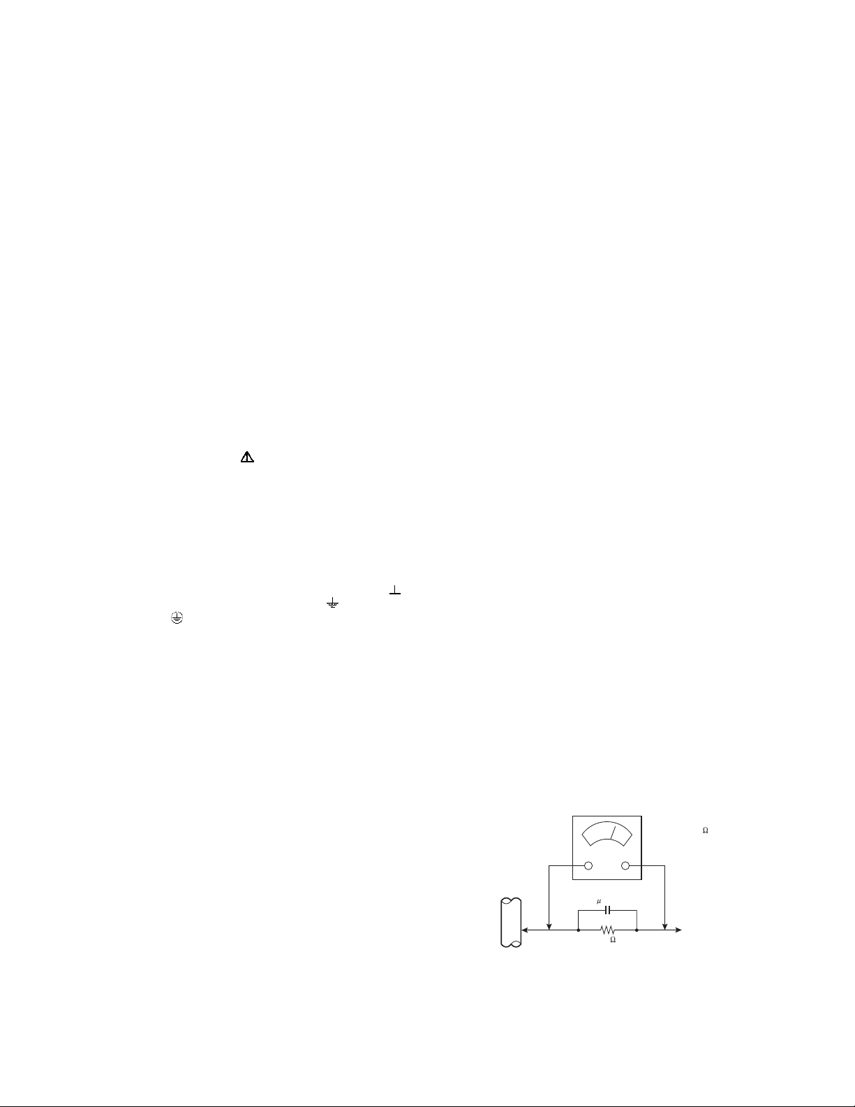
b) Leakage Current Check
Plug the AC line cord directly into the AC outlet (do not use
a line isolation transformer during this check.). Using a
"Leakage Current Tester", measure the leakage current
from each exposed metal part of the cabinet, particularly
any exposed metal part having a return path to the chassis,
to a known good earth ground (water pipe, etc.). Any
leakage current must not exceed 0.5mA AC (r.m.s.).
However, in tropical area, this must not exceed 0.2mA AC
(r.m.s.).
Alternate Check Method
Plug the AC line cord directly into the AC outlet (do not
use a line isolation transformer during this check.). Use
an AC voltmeter having 1000Ω per volt or more
sensitivity in the following manner. Connect a 1500Ω
10W resistor paralleled by a 0.15µF AC-type capacitor
between an exposed metal part and a known good earth
ground (water pipe, etc.). Measure the AC voltage
across the resistor with the AC voltmeter. Move the
resistor connection to each exposed metal part,
particularly any exposed metal part having a return path
to the chassis, and measure the AC voltage across the
resistor. Now, reverse the plug in the AC outlet and
repeat each measurement. Any voltage measured must
not exceed 0.75V AC (r.m.s.). This corresponds to
0.5mA AC (r.m.s.).
However, in tropical area, this must not exceed 0.3V AC
(r.m.s.). This corresponds to 0.2mA AC (r.m.s.).
AC VOLTMETER
(HAVING 1000 /V,
OR MORE SENSITIVITY)
0.15 F AC-TYPE
GOOD EARTH GROUND
1500 10W
PLACE THIS PROBE
ON EACH EXPOSED
ME TAL PAR T
(No.YA492)1-3
Page 4

1.2 SAFETY PRECAUTIONS [FOR UK]
(1) The design of this product contains special hardware and many circuits and components specially for safety purposes. For
continued protection, no changes should be made to the original design unless authorized in writing by the manufacturer.
Replacement parts must be identical to those used in the original circuits. Service should be performed by qualified personnel
only.
(2) Alterations of the design or circuitry of the product should not be made. Any design alterations or additions will void the
manufacturer's warranty and will further relieve the manufacturer of responsibility for personal injury or property damage
resulting therefrom.
(3) Many electrical and mechanical parts in the product have special safety-related characteristics. These characteristics are often
not evident from visual inspection nor can the protection afforded by them necessary be obtained by using replacement
components rated for higher voltage, wattage, etc. Replacement parts which have these special safety characteristics are
identified in the Parts List of Service Manual. Electrical components having such features are identified by shading on the
schematics and by ( ) on the Parts List in the Service Manual. The use of a substitute replacement which does not have the
same safety characteristics as the recommended replacement part shown in the Parts List of Service Manual may cause shock,
fire, or other hazards.
(4) The leads in the products are routed and dressed with ties, clamps, tubing’s, barriers and the like to be separated from live parts,
high temperature parts, moving parts and / or sharp edges for the prevention of electric shock and fire hazard. When service is
required, the original lead routing and dress should be observed, and it should be confirmed that they have been returned to
normal, after re-assembling.
WARNING
(1) The equipment has been designed and manufactured to meet international safety standards.
(2) It is the legal responsibility of the repairer to ensure that these safety standards are maintained.
(3) Repairs must be made in accordance with the relevant safety standards.
(4) It is essential that safety critical components are replaced by approved parts.
(5) If mains voltage selector is provided, check setting for local voltage.
1-4 (No.YA492)
Page 5
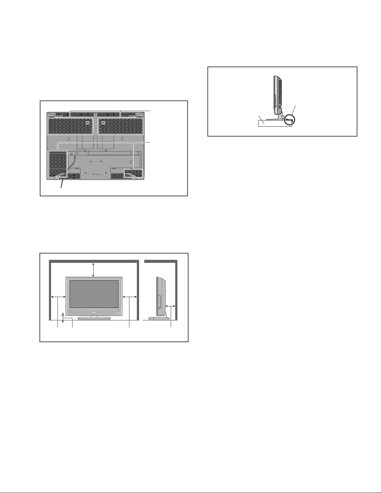
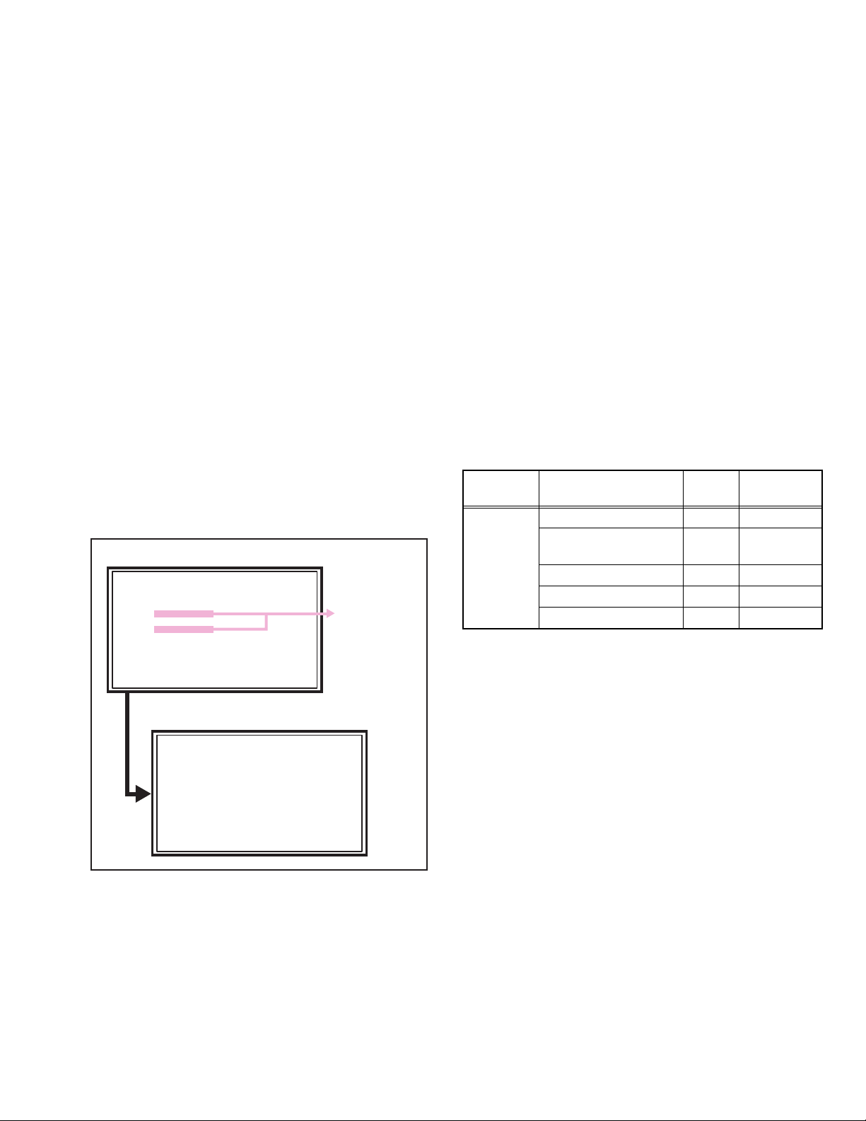
1.3 INSTALLATION
1.3.1 HEAT DISSIPATION
If the heat dissipation vent behind this unit is blocked, cooling
efficiency may deteriorate and temperature inside the unit will
rise. The temperature sensor that protects the unit will be
activated when internal temperature exceeds the pre-determined
level and power will be turned off automatically.Therefore,
please make sure pay attention not to block the heat dissipation
vent as well as the ventilation outlet behind the unit and ensure
that there is room for ventilation around it.
Ventilation hole
Ventilation hole
*Diagram differs from actual appearance.
1.3.2 INSTALLATION REQUIREMENTS
Ensure that the minimal distance is maintained, as specified
below, between the unit with and the surrounding walls, as well
as the floor etc.Install the unit on stable flooring or stands.Take
precautionary measures to prevent the unit from tipping in order
to protect against accidents and earthquakes.
1.3.3 INSTALLATION REQUIREMENTS
To ensure safety in an emergency such as an earthquake, and
to prevent accidents, ensure that measures are taken to prevent
the TV dropping or falling over.
It fixes in a band.
TV Stand
*Diagram differs from actual appearance.
1.3.4 NOTES ON HANDLING
(1) WHEN TAKING UNIT OUT OF A PACKING CASE
When taking the unit out of a packing case, do not grasp
the upper part of the unit. If you take the unit out while
grasping the upper part, the LCD PANEL may be damaged
because of a pressure. Instead of grasping the upper part,
put your hands on the lower backside or sides of the unit.
(2) AS FOR PRESSING OR TOUCHING A SPEAKER
Be careful not to press the opening of the speaker in the
lower part of the unit and around them since the decorative
sheet on the surface of the openings may be deformed.
200 mm
150 mm 50 mm
*Diagram differs from actual appearance.
150 mm 50 mm
(No.YA492)1-5
Page 6

1.4 HANDLING LCD PANEL
1.4.1 PRECAUTIONS FOR TRANSPORTATION
When transporting the unit, pressure exerted on the internal LCD
panel due to improper handling (such as tossing and dropping)
may cause damages even when the unit is carefully packed. To
prevent accidents from occurring during transportation, pay
careful attention before delivery, such as through explaining the
handling instructions to transporters.
Ensure that the following requirements are met during
transportation, as the LCD panel of this unit is made of glass and
therefore fragile:
(1) USE A SPECIAL PACKING CASE FOR THE LCD PANEL
When transporting the LCD panel of the unit, use a special
packing case (packing materials). A special packing case
is used when a LCD panel is supplied as a service spare
part.
(2) ATTACH PROTECTION SHEET TO THE FRONT
Since the front (display part) of the panel is vulnerable,
attach the protection sheet to the front of the LCD panel
before transportation. Protection sheet is used when a LCD
panel is supplied as a service spare part.
(3) AVOID VIBRATIONS AND IMPACTS
The unit may be broken if it is toppled sideways even when
properly packed. Continuous vibration may shift the gap of
the panel, and the unit may not be able to display images
properly. Ensure that the unit is carried by at least 2
persons and pay careful attention not to exert any vibration
or impact on it.
(4) DO NOT PLACE EQUIPMENT HORIZONTALLY
Ensure that it is placed upright and not horizontally during
transportation and storage as the LCD panel is very
vulnerable to lateral impacts and may break. During
transportation, ensure that the unit is loaded along the
traveling direction of the vehicle, and avoid stacking them
on one another. For storage, ensure that they are stacked
in 2 layers or less even when placed upright.
1.4.2 OPTICAL FILTER (ON THE FRONT OF THE LCD PANEL)
(1) Avoid placing the unit under direct sunlight over a
prolonged period of time. This may cause the optical filter
to deteriorate in quality and COLOUR.
(2) Clean the filter surface by wiping it softly and lightly with a
soft and lightly fuzz cloth (such as outing flannel).
(3) Do not use solvents such as benzene or thinner to wipe the
filter surface. This may cause the filter to deteriorate in
quality or the coating on the surface to come off. When
cleaning the filter, usually use the neutral detergent diluted
with water. When cleaning the dirty filter, use water-diluted
ethanol.
(4) Since the filter surface is fragile, do not scratch or hit it with
hard materials. Be careful enough not to touch the front
surface, especially when taking the unit out of the packing
case or during transportation.
1.4.3 PRECAUTIONS FOR REPLACEMENT OF EXTERIOR
PARTS
Take note of the following when replacing exterior parts (REAR
COVER, FRONT PANEL, etc.):
(1) Do not exert pressure on the front of the LCD panel (filter
surface). It may cause irregular COLOUR.
(2) Pay careful attention not to scratch or stain the front of the
LCD panel (filter surface) with hands.
(3) When replacing exterior parts, the front (LCD panel) should
be placed facing downward. Place a mat, etc. underneath
to avoid causing scratches to the front (filter surface).
1-6 (No.YA492)
Page 7
SECTION 2
SPECIFIC SERVICE INSTRUCTIONS
2.1 FEATURES
T-V LINK
When you have a T-V LINK compatible VCR connected to the
EXT-2 Terminal on the TV, it is easier to set up the VCR and
to view videos.
PICTURE MODE
This function can adjust the picture settings automatically.
2.2 MAIN DIFFERENCE LIST
Item LT-26A70BJ LT-26A70SJ LT-26A70BU LT-26A70SU
Paint Color Black Silver Black Silver
Broadcasting System I (UHF / VHF)
RF System PAL
Video System PAL, NTSC
Teletext FLOF / WST
Plug Type UK Type (3 Pins)
Item LT-32A70SJ LT-32A70BJ LT-32A70SU LT-32A70BU LT-32A70GU
Paint Color Black Silver Black Silver Titanium
Broadcasting System I (UHF / VHF)
RF System PAL
Video System PAL, NTSC
Teletext FLOF / WST
Plug Type UK Type (3 Pins)
←
←
←
←
←
←
←
←
←
←
ZOOM
This function can change the screen size according to the
picture aspect ratio.
DIGITAL VNR
This function cuts down the amount of noise in the original
picture.
B/G, D/K, I, L
PAL,SECAM
PAL, SECAM, NTSC
FLOF / TOP / WST
EU Type (2 Pins)
B/G, D/K, I, L
PAL,SECAM
PAL, SECAM, NTSC
FLOF / TOP / WST
EU Type (2 Pins)
←
←
←
←
←
←←
←←
←←
←←
←←
(No.YA492)1-7
Page 8
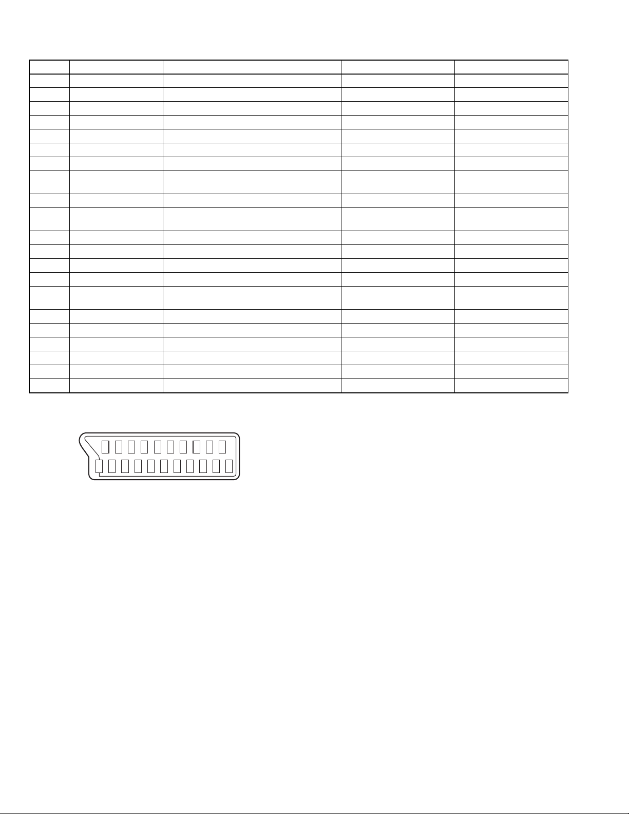
2.3 21-PIN EURO CONNECTOR (SCART) : EXT-1 / EXT-2
Pin No. Signal designation Matching value EXT-1 EXT-2
1 AUDIO R output 500mV(rms) (Nominal), Low impedance Used (TV OUT) Used (LINE OUT)
2 AUDIO R input 500mV(rms) (Nominal), High impedance Used (R1) Used (R2)
3 AUDIO L output 500mV(rms) (Nominal), Low impedance Used (TV OUT) Used (LINE OUT)
4 AUDIO GND Used Used
5 GND (B) Used Used
6 AUDIO L input 500mV(rms) (Nominal), High impedance Used (L1) Used (L2)
7 B input 700mV
8 FUNCTION SW
(SLOW SW)
Low : 0V-3V
High : 8V-12V, High impedance
, 75Ω Used Used
(B-W)
Used Used
9 GND (G) Used Used
10 SCL / T-V LINK Not used Used
(SCL2 / TV-LINK)
11 G input 700mV
, 75Ω Used Used
(B-W)
12 SDA Not used Used (SDA2)
13 GND (R) Used Used
14 GND (YS) Used Not used
15 R / C input R : 700mV
C : 300mV
(B-W)
(P-P)
, 75Ω
, 75Ω
Used (R) Used (C2/R)
16 Ys input (FAST SW) Low : 0V-0.4V, High : 1V-3V, 75Ω Used Used
17 GND (VIDEO output) Used Used
18 GND (VIDEO input) Used Used
19 VIDEO output 1V
20 VIDEO / Y input 1V
(Negative sync), 75Ω Used (TV OUT) Used (LINE OUT)
(P-P)
(Negative sync), 75Ω Used Used
(P-P)
21 COMMON GND Used Used
(P-P= Peak to Peak, B-W= Blanking to white peak)
[Pin assignment]
20 18 16 14 12 10 8 6 4 2
21 19 17 15 13 11 9 7 5 3 1
1-8 (No.YA492)
Page 9
2.4 TECHNICAL INFORMATION
2.4.1 LCD PANEL
This unit uses the flat type panel LCD (Liquid Crystal Display) panel that occupies as little space as possible, instead of the
conventional CRT (Cathode Ray Tube), as a display unit.
Since the unit has the two polarizing filter that are at right angles to each other, the unit adopts "normally black" mode, where light
does not pass through the polarizing filter and the screen is black when no voltage is applied to the liquid crystals.
2.4.1.1 SPECIFICATIONS
The following table shows the specifications of this unit.
Item
Maximum dimensions ( W × H × D )
Weight 4.5 kg 6.9 kg
Effective screen size Diagonal: 660 mm (H: 576 mm × V: 324 mm) Diagonal: 800 mm (H: 697 mm × V: 392 mm)
Aspect ratio 16 : 9
Drive device / system a-Si-TFT active matrix system
Resolution Horizontally 1366 × Vertically 768 × RGB < W-XGA > 3147264 dots in total
Pixel pitch (pixel size) Horizontally: 0.4215 mm, Vertically: 0.4215 mm Horizontally: 0.51075 mm, Vertically: 0.51075 mm
Displayed colour 16777216 colours 256 colours for R G and B
Brightness 500cd/m2
Contrast ratio 1200 : 1
Response time (Tr) less than 8 ms
View angle (Horizontally) 176°
View angle (Vertically) 176°
Surface polarizer Anti-Glare type Low reflective coat
Colour filter Vertical stripe
Backlight Cold cathode fluorescent lamp × 6 Cold cathode fluorescent lamp × 12
Power supply voltage in LCD 5 V
Power supply voltage in inverter
Panel interface system LVDS (Low Voltage Differential Signaling)
62.6 cm × 37.3 cm × 4.8 cm 76.0 cm × 45.0 cm × 4.5 cm
24 V
26V LCD PANEL UNIT 32V LCD PANEL UNIT
Specifications
2.4.1.2 PIXEL FAULT
There are three pixel faults - bright fault , dark fault and flicker fault - that are respectively defined as follows.
BRIGHT FAULT
In this pixel fault, a cell that should not light originally is lighting on and off.
For checking this pixel fault, input ALL BLACK SCREEN and find out the cell that is lighting on and off.
DARK FAULT
In this pixel fault, a cell that should light originally is not lighting or lighting with the brightness twice as brighter as originally lighting.
For checking this pixel fault, input 100% of each R/G/B colour and find out the cell that is not lighting.
FLICKER FAULT
In the pixel fault, a cell that should light originally or not light originally is flashing on and off.
For checking this pixel fault, input ALL BLACK SCREEN signal or 100% of each RGB colour and find out the cell that is flashing on
and off.
(No.YA492)1-9
Page 10

2.4.2 MAIN CPU PIN FUNCTION [IC3
Pin Pin name I/O Function Pin Pin name I/O Function
1 P9_4 O PANEL_POWER_CONTROL 51 A17 O Program ROM address for CPU
2 P9_3 O POWER 52 A16 O Program ROM address for CPU
3 P9_2 O SC_RGB_CONTROL 53 A15 O Program ROM address for CPU
4 P9_1 O SOUNDAMP_POWER 54 A14 O Program ROM address for CPU
5 HP_DET I HEADPHONE_DETECT 55 A13 O Program ROM address for CPU
6 BYTE I BYTE 56 A12 O Program ROM address for CPU
7 CNVSS I CNVSS 57 A11 O Program ROM address for CPU
8 XCIN - Not used 58 A10 O Program ROM address for CPU
9 XCOUT - Not used 59 A9 O Program ROM address for CPU
10 CPU_RESET I /RESET 60 VCC2 I 3.3V
11 XOUT O XOUT 61 A8 O Program ROM address for CPU
12 VSS - VSS 62 VSS - VSS
13 XIN I XIN 63 A7 O Program ROM address for CPU
14 VCC1 I 3.3V 64 A6 O Program ROM address for CPU
15 P8_5 - Not used 65 A5 O Program ROM address for CPU
16 P8_4 - Not used 66 A4 O Program ROM address for CPU
17 /INT1 I PX_INT# 67 A3 O Program ROM address for CPU
18 /INT0 I REMOCON 68 A2 O Program ROM address for CPU
19 P8_1 - Not used 69 A1 O Program ROM address for CPU
20 P8_0 O LED_ON 70 A0 O Program ROM address for CPU
21 P7_7 O HDMI_DETECT 71 P1_7 - Not used
22 P7_6 O SOUNDAMP MUTE 72 P1_6 - Not used
23 P7_5 I DEBUG 73 P1_5 I TV_LINK_IN
24 P7_4 O BACKLIGHT_CONTROL 74 P1_4 O EDID_WP
25 P7_3 O HDMI_DAC_MUTE 75 P1_3 - Not used
26 P7_2 - Not used 76 P1_2 O TV_LINK_CONTROL
27 P7_1 I/O SCL_EEP 77 P1_1 O TV_LINK_OUT
28 P7_0 I/O SDA_EEP 78 P1_0 I HDMI_PICTURE_SIGNAL_INDICATON
29 P6_7 I/O TX 79 D7 I/O Program ROM data for CPU
30 P6_6 I/O RX 80 D6 I/O Program ROM data for CPU
31 P6_5 I/O DEBUG3 81 D5 I/O Program ROM data for CPU
32 P6_4 I/O DEBUG2 82 D4 I/O Program ROM data for CPU
33 P6_3 I/O SDA_DEVICE 83 D3 I/O Program ROM data for CPU
34 P6_2 I/O SCL_DEVICE 84 D2 I/O Program ROM data for CPU
35 P6_1 O RESET_for_PX 85 D1 I/O Program ROM data for CPU
36 P6_0 O RESET_for_MSP 86 D0 I/O Program ROM data for CPU
37 P5_7 - Not used 87 AN7 I TUNER AGC
38 ALE O PX,FLASH_ALE 88 AN6 I TUNER AFT
39 P5_5 I/O DEBUG6 89 AN5 I LOW VOLTAGE_PROTECTION
40 P5_4 - Not used 90 AN4 I HDMI_PROTECTION
41 P5_3 - Not used 91 AN3 I POWER_DET
42 /RD O PX,FLASH_RD# 92 AN2 I KEYA
43 /WRH /BHE O RY_BY 93 AN1 I KEYB
44 /WR O PX,FLASH_WR# 94 VSS - VSS
45 /CS3 - Not used 95 AN0 - Not used
46 /CS2 O PX_CHIPSELECT# 96 VREF I 3.3V
47 /CS1 - Not used 97 AVCC I 3.3V
48 /CS0 O FLASH_CHIPSELECT# 98 P9_7 O AUDIO_MUTE
49 A19 O Program ROM address for CPU 99 P9_6 O BACKLIGHT_POWER
50 A18 O Program ROM address for CPU 100 P9_5 O EEP_WP
: MAIN PWB]
1-10 (No.YA492)
Page 11

SECTION 3
DISASSEMBLY
3.1 DISASSEMBLY PROCEDURE
CAUTION AT DISASSEMBLY:
• Make sure that the power cord is disconnected from the outlet.
• Pay special attention not to break or damage the parts.
• When removing each board, remove the connectors as required. Taking notes of the connecting points (connector numbers)
makes service procedure manageable.
• Make sure that there is no bent or stain on the connectors before inserting, and firmly insert the connectors.
3.1.1 REMOVING THE STAND
(1) Remove the 4 screws [A], then remove the STAND ASS'Y.
3.1.2 REMOVING THE REAR COVER AND BACK BRACKET
• Remove the STAND.
(1) Remove the 8 screws [B], 3 screw [C].
(2) Remove the REAR COVER.
(3) Remove the 4 screws [D].
(4) Remove the BACK BRACKET.
3.1.3 REMOVING THE POWER PWB
• Remove the STAND.
• Remove the REAR COVER.
• Remove the POWER CORD.
(1) Remove the 4 screws [E].
(2) Remove the POWER PWB.
3.1.4 REMOVING THE MAIN PWB
• Remove the STAND.
• Remove the REAR COVER.
(1) Remove the 3 screws [F] and 2 screws [G].
(2) Remove the TERMINAL BASE.
(3) Remove the 8 screws [H] and 1 screw [J].
(4) Remove the SHIELD COVER.
(5) Remove the 4 screws [K] .
(6) Remove the MAIN PWB.
3.1.6 REMOVING THE IR PWB
• Remove the STAND.
• Remove the REAR COVER.
(1) Remove the 2 screws [M].
(2) Remove the IR PWB.
3.1.7 REMOVING THE SPEAKER HOLDER AND SPEAKER
• Remove the STAND.
• Remove the REAR COVER.
(1) Remove the 2 screws [P].
(2) Remove the SPEAKER with the SPEAKER HOLDER.
(3) Remove the 4 screws [N].
(4) Remove the SPEAKER.
(5) The other SPEAKER HOLDER AND SPEAKER are
removed according to similar procedure.
3.1.8 REMOVING THE LCD PANEL UNIT
• Remove the STAND.
• Remove the REAR COVER.
• Remove the TERMINAL BASE.
(1) Remove the 2 screws [Q] and 1 screw [R].
(2) Remove the STAND BRACKET.
(3) Remove the 4 screws [S].
(4) Remove the MAIN BASE.
(5) Remove the 6 screws [T].
(6) Remove the LCD PANEL UNIT.
3.1.5 REMOVING THE CONTROL KNOB ASS'Y AND
CONTROL PWB
• Remove the STAND.
• Remove the REAR COVER.
(1) Remove the 2 screws [L].
(2) Remove the CONTROL PWB with the CONTROL KNOB
ASS'Y.
(3) Remove the CONTROL PWB from the CONTROL KNOB
ASS'Y.
(No.YA492)1-11
Page 12
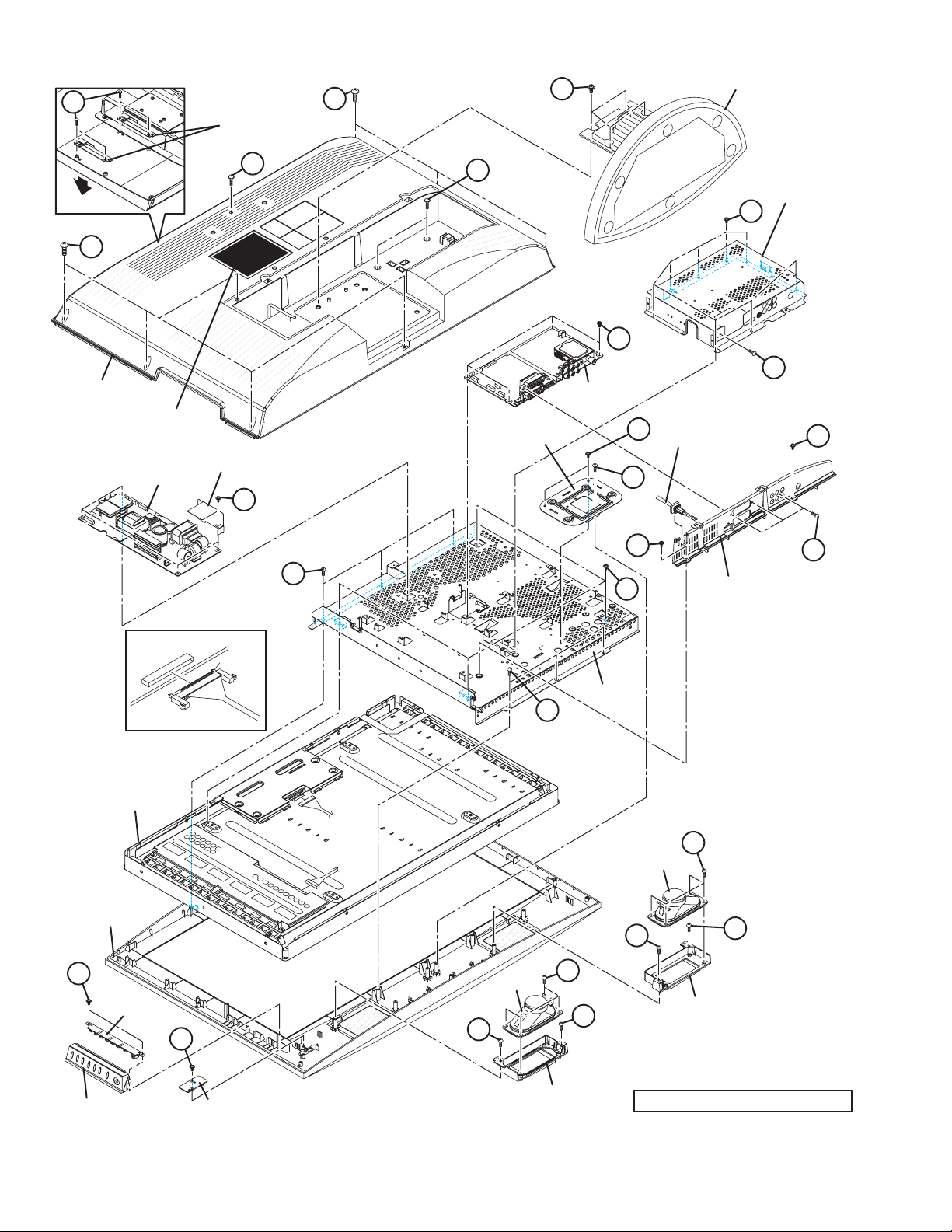
D
BACK BRACKET
B
A
STAND ASS'Y
REAR SIDE
B
REAR COVER
RATING LABEL
POWER PWB
INSULATOR
E
C
C
SHIELD COVER
H
K
J
MAIN PWB
STNAD
BRACKET
Q
POWER CORD
G
R
G
F
T
S
TERMINAL BASE
LCD PANEL UNIT
FRONT BASE
L
CONTROL PWB
The terminal of a connector is turned up and connected.
+PUGTVCPFNQEMUWTGN[
terminal side
Check that connector is inserted completly.
(Don't insert aslant)
M
SPEAKER
P
T
MAIN BASE
N
P
SPEAKER
P
N
P
SPEAKER
HOLDER
CONTROL KNOB ASS'Y IR PWB
1-12 (No.YA492)
Fig.1
SPEAKER
HOLDER
This illustration is LT-32A70 series.
Page 13
3.2 MEMORY IC REPLACEMENT
S001 5I R OF 126
PAL50 FULL STD H
SERVICE MENU
1.ADJUST
2.SELF_CHECK
3.I2C STOP
4.OPTION
• This model uses the memory IC.
• This memory IC stores data for proper operation of the video and drive circuits.
• When replacing, be sure to use an IC containing this (initial value) data.
3.2.1 MEMORY IC REPLACEMENT PROCEDURE
1. Power off
Switch off the power and disconnect the power plug from the AC outlet.
2. Replace the memory IC
Be sure to use the memory IC written with the initial setting values.
3. Power on
Connect the power plug to the AC outlet and switch on the power.
4. Receiving channel setting
Refer to the OPERATING INSTRUCTIONS and set the receive channels (Channels Preset) as described.
5. User setting
Check the user setting items according to the given in page later. Where these do not agree, refer to the OPERATING
INSTRUCTIONS and set the items as described.
6. SERVICE MODE setting
Verify what to set in the SERVICE MODE, and set whatever is necessary (Fig.1). Refer to the SERVICE ADJUSTMENT for setting.
3.2.2 SERVICE MODE SETTING
SERVICE MODE SCREEN
NOTE:
As self check feature is not used in this TV,
"2.SELF_CHECK" and "4.OPTION" cannot be selected
(screen display only).
SETTING ITEM
Setting
items
Setting items Settings Item No.
1.ADJUST Video system setting -1 Adjust S001 - S096
Video system setting -2 Fixed D001 - D020
SERVICE MODE SCREEN
D031 - D099
Audio System Setting -1 Fixed A001 - A003
SERVICE MENU
1.ADJUST
2.SELF_CHECK
3.I2C STOP
4.OPTION
Not used
(Display only)
Audio system setting -2 Fixed SD10 - SD15
Option Setting Fixed O001 - O004
1. ADJUST
S001 5I R OF 126
PAL50 FULL STD H
Fig.1
(No.YA492)1-13
Page 14
3.2.3 SETTINGS OF FACTORY SHIPMENT
3.2.3.1 BUTTON OPERATION 3.2.3.2 REMOTE CONTROL DIRECT OPERATION
Setting item Setting position
POWER Off
CHANNEL PR1
VOLUME 10
TV/AV TV
3.2.3.3 REMOTE CONTROL MENU OPERATION
(1) PICTURE
Setting item Setting position
PICTURE MODE BRIGHT
COLOUR TEMP. COOL
FEATURES
DIGITAL VNR AUTO (LOW)
COLOUR SYSTEM TV Depends on PR/CH
EXT AUTO
4:3 AUTO ASPECT PANORAMIC
(2) SOUND
Setting item Setting position
STEREO / I•II Stereo sound
BASS Centre
TREBLE Centre
BALANCE Centre
3D SOUND OFF
CHANNEL PR1
VOLUME 10
ZOOM AUTO
3D SOUND OFF
SUB POWER OFF
(4) FEATURES
SLEEP TIMER OFF
CHILD LOCK ID NO.0000, All CH off
APPEARANCE TYPE A
BLUE BACK ON
FAVOURITE SETTING Reset
(5) SET UP
AUTO PROGRAM TV channel automatically set
EDIT/MANUAL PRESET CH only
LANGUAGE ENGLISH
DECODER (EXT-2) OFF
EXT SETTING
S-IN BLANK
ID BLANK
DUBBING EXT-1 → EXT-2
Setting item Setting position
Setting item Setting position
Setting item Setting position
1-14 (No.YA492)
Page 15
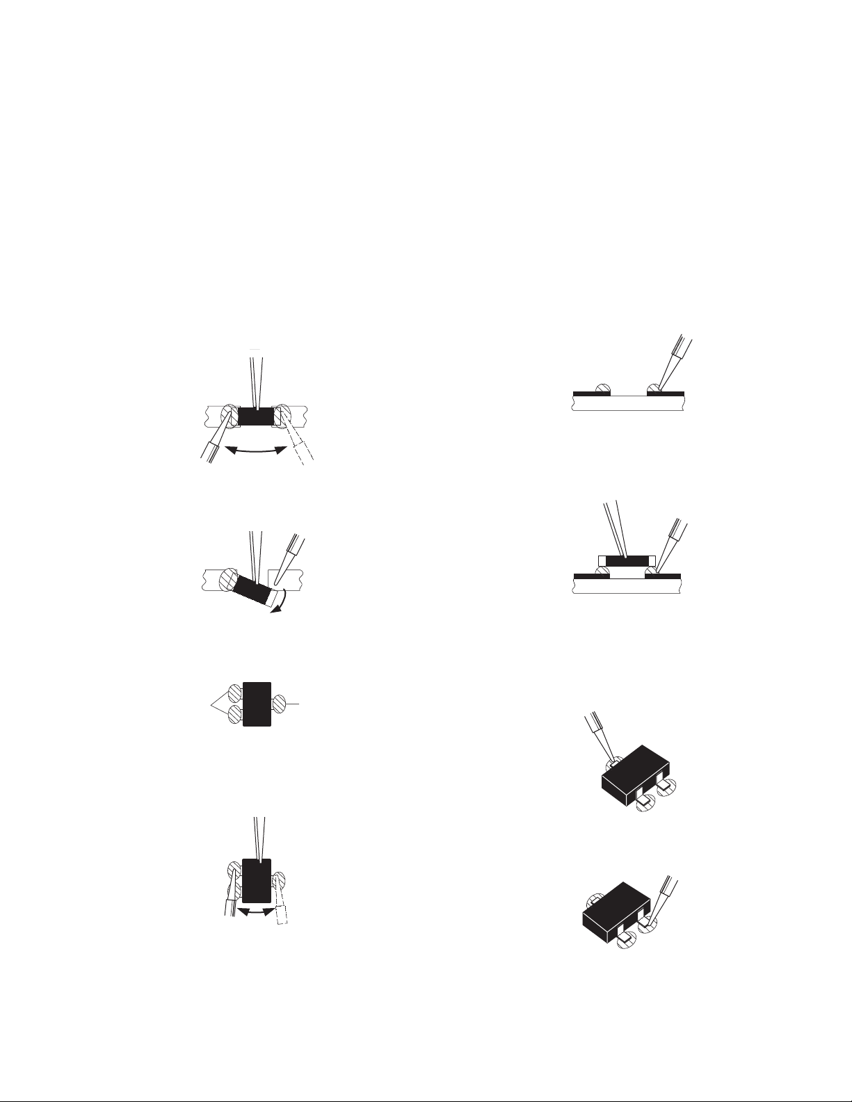
3.3 REPLACEMENT OF CHIP COMPONENT
3.3.1 CAUTIONS
(1) Avoid heating for more than 3 seconds.
(2) Do not rub the electrodes and the resist parts of the pattern.
(3) When removing a chip part, melt the solder adequately.
(4) Do not reuse a chip part after removing it.
3.3.2 SOLDERING IRON
(1) Use a high insulation soldering iron with a thin pointed end of it.
(2) A 30w soldering iron is recommended for easily removing parts.
3.3.3 REPLACEMENT STEPS
1. How to remove Chip parts
2. How to install Chip parts
[Resistors, capacitors, etc.]
(1) As shown in the figure, push the part with tweezers and
alternately melt the solder at each end.
(2) Shift with the tweezers and remove the chip part.
[Transistors, diodes, variable resistors, etc.]
(1) Apply extra solder to each lead.
SOLDER
SOLDER
[Resistors, capacitors, etc.]
(1) Apply solder to the pattern as indicated in the figure.
(2) Grasp the chip part with tweezers and place it on the
solder. Then heat and melt the solder at both ends of the
chip part.
[Transistors, diodes, variable resistors, etc.]
(1) Apply solder to the pattern as indicated in the figure.
(2) Grasp the chip part with tweezers and place it on the
solder.
(3) First solder lead A as indicated in the figure.
(2) As shown in the figure, push the part with tweezers and
alternately melt the solder at each lead. Shift and remove
the chip part.
NOTE :
After removing the part, remove remaining solder from the
pattern.
A
B
C
(4) Then solder leads B and C.
A
B
C
(No.YA492)1-15
Page 16
SECTION 4
SERVICE MENU
1.ADJUST
2.SELF_CHECK
3.I2C STOP
4.OPTION
ADJUSTMENT
4.1 ADJUSTMENT PREPARATION
(1) The adjustment using the REMOTE CONTROL UNIT is
made on the basis of the initial setting values. The
setting values which adjust the screen to the optimum
condition can be different from the initial setting
values.
(2) Make sure that connection is correctly made AC to AC
power source.
(3) Turn on the power of the TV and measuring instruments for
warming up for at least 30 minutes before starting
adjustments.
(4) If the receive or input signal is not specified, use the most
appropriate signal for adjustment.
(5) Never touch the parts (such as variable resistors,
transformers and condensers) not shown in the adjustment
items of this service adjustment.
4.2 PRESET SETTING BEFORE ADJUSTMENTS
Unless otherwise specified in the adjustment items, preset the
following functions with the REMOTE CONTROL UNIT.
Setting item Settings position
PICTURE MODE STANDARD
PICTURE adjustments Centre
COLOUR TEMP. NORMAL
4.3 MEASURING INSTRUMENT AND FIXTURES
• Signal generator (Pattern generator)[PAL]
• Remote control unit
4.4 ADJUSTMENT ITEMS
VIDEO CIRCUIT
• WHITE BALANCE (HIGH LIGHT) adjustment
4.5 BASIC OPERATION OF SERVICE MODE
4.5.1 SERVICE MODE SELECT KEY LOCATION
MUTING
NUMBER
INFORMATION
FUNCTION /
VCR/TV/DVD
switch
MENU
FUNCTION /
4.5.2 HOW TO ENTER THE SERVICE MODE
(1) Press [INFORMATION] key and [MUTING] key on the
remote control unit simultaneously to enter the SERVICE
MODE SCREEN. (Fig.1)
SERVICE MODE SCREEN
SERVICE MENU
1.ADJUST
2.SELF_CHECK
3.I2C STOP
4.OPTION
Not used
(Display only)
Fig.1
NOTE:
• As self check feature is not used in this TV,
"2.SELF_CHECK" and "4.OPTION"cannot be selected
(screen display only).
• Before entering the SERVICE MODE, confirm that the
setting of VCR/TV/DVD switch is at the "TV" side. If the
switches have not been properly set, you cannot enter the
SERVICE MODE.”
4.5.3 HOW TO EXIT THE SERVICE MODE
Press the [MENU] key to exit the Service mode.
4.5.4 CHANGE AND MEMORY OF SETTING VALUE
SELECTION OF SETTING ITEM
• [FUNCTION /] key.
For scrolling up / down the setting items.
CHANGE OF SETTING VALUE (DATA)
• [FUNCTION /] key.
For scrolling up / down the setting values.
MEMORY OF SETTING VALUE (DATA)
Changed setting value is memorized by pressing [MUTING]
key.
4.5.5 ADJUSTMENT MODE
This mode is used to adjust the VIDEO CIRCUIT.
4.5.5.1 HOW TO ENTER THE ADJUSTMENT MODE
When the SERVICE MENU SCREEN of SERVICE MODE is
displayed, press [1] key to enter the ADJUSTMENT MODE
(Fig.2).
NOTE:
• When a number key other than the [1] key is pressed in the
SERVICE MODE SCREEN, the other relevant screen may
be displayed.
This is not used in the adjustment procedure. Press the
[MENU] key to return to the SERVICE MODE SCREEN.
1-16 (No.YA492)
Page 17
4.5.5.2 DESCRIPTION OF STATUS DISPLAY
S001 5I R OF 126
PAL50 FULL STD H
SETTING VALUE (DATA)SETTINGITEM No. SETTING ITEM
S001 5I R OF 126
PAL50 FULL STD H
SIGNAL SYSTEM
ZOOM MODE
PICTURE MODE
(1) SIGNAL SYSTEM
The signal displayed on the screen is displayed.
PAL50 : PAL50Hz
PAL60 : PAL60Hz
SECAM : SECAM
NTSC3 : NTSC3.58
NTSC4 : NTSC4.43
H525I : 525i(Component/HDMI)
H625I : 625i(Component/HDMI)
H525P : 525p(Component/HDMI)
H625P : 625p(Component/HDMI)
H750P : 750p(Component/HDMI)
H125I : 1125i(Component/HDMI)
VGA : VGA(HDMI)
COLOUR TEMP.
(4) WHITE BALANCE
State of the colour temperature is displayed.
NOTE:
In ADJUSTMENT MODE, the colour temperature can be set
only to "NORMAL". When it is entered to ADJUSTMENT
MODE, it is automatically changed to "NORMAL", even if
the setting is in other colour temperature.
(5) SETTING ITEM NAME
Setting item name are displayed. The setting item numbers to
be displayed are listed below.
Item No. Setting item
S001 - S043 Video system setting -1
D001 - D020
Video system setting -2 [Do not adjust]
D031 - D099
A001 - A003 Audio system setting -1 [Do not adjust]
SD10 - SD15 Audio system setting -2 [Do not adjust]
O001 - O004 Option data setting [Not used]
(6) SETTING ITEM NO.
Setting item numbers are displayed. For the setting item
names to be displayed, refer to "INITIAL SETTING VALUES
IN THE SERVICE MODE".
(7) SETTING VALUE (DATA)
The SETTING VALUE is displayed.
(2) ZOOM MODE
State of the screen mode is displayed.
NOTE:
In ADJUSTMENT MODE, the screen mode can be set only
to "FULL". When it is entered to ADJUSTMENT MODE, it is
automatically changed to "FULL", even if the setting is in
other screen mode.
(3) PICTURE MODE
State of the picture mode is displayed.
NOTE:
In ADJUSTMENT MODE, the picture mode can be set only
to "STANDARD". When it is entered to ADJUSTMENT
MODE, it is automatically changed to "STANDARD", even
if the setting is in other picture mode.
(No.YA492)1-17
Page 18

4.6 INITIAL SETTING VALUES IN THE SERVICE MODE
• Perform fine-tuning based on the "initial values" using the remote control when in the Service mode.
• The "initial values" serve only as an indication rough standard and therefore the values with which optimal display can be achieved
may be different from the default values. But, don't change the values that are not written in "ADJUSTMENT PROCEDURE". They
are fixed values.
4.6.1 ADJUSTMENT MODE
4.6.1.1 VIDEO SYSTEM SETTING-1
Item No. Item name Variable range Setting value
S001 CVBS R OF 0 - 255 130
S002 CVBS G OF 0 - 255 130
S003 CVBS B OF 0 - 255 129
S004 5I R OF 0 - 255 0
S005 5I G OF 0 - 255 0
S006 5I B OF 0 - 255 0
S007 5P R OF 0 - 255 0
S008 5P G OF 0 - 255 0
S009 5P B OF 0 - 255 0
S010 HD75 R OF 0 - 255 0
S011 HD75 G OF 0 - 255 0
S012 HD75 B OF 0 - 255 0
S013 HD25 R OF 0 - 255 0
S014 HD25 G OF 0 - 255 0
S015 HD25 B OF 0 - 255 0
S016 HDMI5I R OF 0 - 255 0
S017 HDMI5I G OF 0 - 255 0
S018 HDMI5I B OF 0 - 255 0
S019 HDMI5P R OF 0 - 255 0
S020 HDMI5P G OF 0 - 255 0
S021 HDMI5P B OF 0 - 255 0
S022 HDMI75 R OF 0 - 255 0
S023 HDMI75 G OF 0 - 255 0
S024 HDMI75 B OF 0 - 255 0
S025 HDMI25 R OF 0 - 255 0
S026 HDMI25 G OF 0 - 255 0
S027 HDMI25 B OF 0 - 255 0
S028 HDMIPC R OF 0 - 255 0
S029 HDMIPC G OF 0 - 255 2
S030 HDMIPC B OF 0 - 255 0
S031 CVBS R DR 0 - 255 131
S032 CVBS G DR 0 - 255 146
S033 CVBS B DR 0 - 255 127
S034 5I R DR 0 - 255 0
S035 5I G DR 0 - 255 0
S036 5I B DR 0 - 255 0
S037 5P R DR 0 - 255 0
S038 5P G DR 0 - 255 0
S039 5P B DR 0 - 255 0
S040 HD75 R DR 0 - 255 0
S041 HD75 G DR 0 - 255 0
S042 HD75 B DR 0 - 255 0
S043 HD25 R DR 0 - 255 0
Item No. Item name Variable range Setting value
S044 HD25 G DR 0 - 255 0
S045 HD25 B DR 0 - 255 0
S046 HDMI5I R DR 0 - 255 0
S047 HDMI5I G DR 0 - 255 0
S048 HDMI5I B DR 0 - 255 0
S049 HDMI5P R DR 0 - 255 0
S050 HDMI5P G DR 0 - 255 0
S051 HDMI5P B DR 0 - 255 0
S052 HDMI75 R DR 0 - 255 0
S053 HDMI75 G DR 0 - 255 0
S054 HDMI75 B DR 0 - 255 0
S055 HDMI25 R DR 0 - 255 0
S056 HDMI25 G DR 0 - 255 0
S057 HDMI25 B DR 0 - 255 0
S058 HDMIPC R DR 0 - 255 0
S059 HDMIPC G DR 0 - 255 0
S060 HDMIPC B DR 0 - 255 0
S061 CVBS CL R OF 0 - 255 0
S062 CVBS CL G OF 0 - 255 0
S063 CVBS CL B OF 0 - 255 0
S064 CVBS WM R OF 0 - 255 0
S065 CVBS WM G OF 0 - 255 0
S066 CVBS WM B OF 0 - 255 0
S067 HD CL R OF 0 - 255 0
S068 HD CL G OF 0 - 255 0
S069 HD CL B OF 0 - 255 0
S070 HD WM R OF 0 - 255 0
S071 HD WM G OF 0 - 255 0
S072 HD WM B OF 0 - 255 0
S073 HDMI CL R OF 0 - 255 0
S074 HDMI CL G OF 0 - 255 0
S075 HDMI CL B OF 0 - 255 0
S076 HDMI WM R OF 0 - 255 0
S077 HDMI WM G OF 0 - 255 0
S078 HDMI WM B OF 0 - 255 0
S079 CVBS CL R DR 0 - 255 255
S080 CVBS CL G DR 0 - 255 0
S081 CVBS CL B DR 0 - 255 3
S082 CVBS WM R DR 0 - 255 8
S083 CVBS WM G DR 0 - 255 0
S084 CVBS WM B DR 0 - 255 242
S085 HD CL R DR 0 - 255 255
S086 HD CL G DR 0 - 255 0
S087 HD CL B DR 0 - 255 3
1-18 (No.YA492)
Page 19

Item No. Item name Variable range Setting value
S088 HD WM R DR 0 - 255 6
S089 HD WM G DR 0 - 255 0
S090 HD WM B DR 0 - 255 233
S091 HDMI CL R DR 0 - 255 255
S092 HDMI CL G DR 0 - 255 0
S093 HDMI CL B DR 0 - 255 3
S094 HDMI WM R DR 0 - 255 8
S095 HDMI WM G DR 0 - 255 0
S096 HDMI WM B DR 0 - 255 242
4.6.1.2 VIDEO SYSTEM SETTING-2
Item No. Item name Variable range Setting value
D001 CVBS NTSC CON 0 - 255 0
D002 CVBS NTSC BRI 0 - 255 0
D003 CVBS NTSC SHA 0 - 255 0
D004 CVBS NTSC COL 0 - 255 0
D005 CVBS NTSC TIN 0 - 255 0
D006 CVBS PAL CON 0 - 255 0
D007 CVBS PAL BRI 0 - 255 0
D008 CVBS PAL SHA 0 - 255 0
D009 CVBS PAL COL 0 - 255 0
D010 CVBS PAL TIN 0 - 255 0
D011 CVBS SECAM CON 0 - 255 0
D012 CVBS SECAM BRI 0 - 255 0
D013
D014 CVBS SECAM COL 0 - 255 0
D015 CVBS SECAM TIN 0 - 255 0
D016 TV PAL CON 0 - 255 0
D017 TV PAL BRI 0 - 255 0
D018 TV PAL SHA 0 - 255 0
D019 TV PAL COL 0 - 255 0
D020 TV PAL TIN 0 - 255 0
D031 TV SECAM CON 0 - 255 0
D032 TV SECAM BRI 0 - 255 0
D033 TV SECAM SHA 0 - 255 0
D034 TV SECAM COL 0 - 255 0
D035 TV SECAM TIN 0 - 255 0
D036 5I S CON 0 - 255 0
D037 5I S BRI 0 - 255 0
D038 5I S SHA 0 - 255 0
D039 5I S COL 0 - 255 0
D040 5I S TIN 0 - 255 0
D041 5P S CON 0 - 255 0
D042 5P S BRI 0 - 255 0
D043 5P S SHA 0 - 255 0
D044 5P S COL 0 - 255 0
D045 5P S TIN 0 - 255 0
D046 HD75 S CON 0 - 255 0
D047 HD75 S BRI 0 - 255 0
CVBS SECAML SHA
0 - 255 0
Item No. Item name Variable range Setting value
D048 HD75 S SHA 0 - 255 0
D049 HD75 S COL 0 - 255 0
D050 HD75 S TIN 0 - 255 0
D051 HD25 S CON 0 - 255 0
D052 HD25 S BRI 0 - 255 0
D053 HD25 S SHA 0 - 255 0
D054 HD25 S COL 0 - 255 0
D055 HD25 S TIN 0 - 255 0
D056 HDMI5I S CON 0 - 255 0
D057 HDMI5I S BRI 0 - 255 0
D058 HDMI5I S SHA 0 - 255 0
D059 HDMI5I S COL 0 - 255 0
D060 HDMI5I S TIN 0 - 255 0
D061 HDMI5P S CON 0 - 255 0
D062 HDMI5P S BRI 0 - 255 0
D063 HDMI5P S SHA 0 - 255 0
D064 HDMI5P S COL 0 - 255 0
D065 HDMI5P S TIN 0 - 255 0
D066 HDMI75 S CON 0 - 255 0
D067 HDMI75 S BRI 0 - 255 0
D068 HDMI75 S SHA 0 - 255 0
D069 HDMI75 S COL 0 - 255 0
D070 HDMI75 S TIN 0 - 255 0
D071 HDMI25 S CON 0 - 255 0
D072 HDMI25 S BRI 0 - 255 0
D073 HDMI25 S SHA 0 - 255 0
D074 HDMI25 S COL 0 - 255 0
D075 HDMI25 S TIN 0 - 255 0
D076 HDMIPC S CON 0 - 255 0
D077 HDMIPC S BRI 0 - 255 0
D078 HDMIPC S SHA 0 - 255 0
D079 HDMIPC S COL 0 - 255 0
D080 HDMIPC S TIN 0 - 255 0
D081 STD BRI1 0 - 255 0
D082 STD CON 0 - 255 8
D083 STD BRI2 0 - 255 247
D084 STD SHA 0 - 255 20
D085 STD COL 0 - 255 245
D086 STD TIN 0 - 255 0
D087 SFT BRI1 0 - 255 245
D088 SFT CON 0 - 255 8
D089 SFT BRI2 0 - 255 249
D090 SFT SHA 0 - 255 20
D091 SFT COL 0 - 255 245
D092 SFT TIN 0 - 255 0
D093 BRI BRI1 0 - 255 10
D094 BRI CON 0 - 255 18
D095 BRI BRI2 0 - 255 249
D096 BRI SHA 0 - 255 25
D097 BRI COL 0 - 255 250
(No.YA492)1-19
Page 20

Item No. Item name Variable range Setting value
D098 BRI TIN 0 - 255 0
D099 PWM 0 - 255 114
4.6.1.3 AUDIO SYSTEM SETTING-1
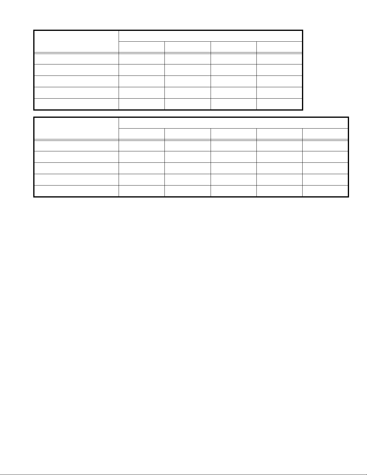
Item No. Item name Variable range Setting value
A001 S BASS 0 - 255 114
A002 S TRE 0 - 255 114
A003 3D LEVEL 0 - 255 114
4.6.1.4 AUDIO SYSTEM SETTING-2
Item No. Item name Variable range Setting value
SD10 S BASS 0 - 255 0
SD11 S TRE 0 - 255 0
SD12 3D LEVEL1 0 - 255 127
SD13 3D LEVEL2 0 - 255 53
SD14 3D LEVEL3 0 - 255 127
SD15 NICAM LEVEL 0 - 255 32
4.6.1.5 OPTION SETTING
Item No. Item name Variable range Setting value
O001 G T 0 - 5 0
O002 D 0 - 2 0
O003 HPD SW 0 - 1 0
O004 HPD D 0 - 255 0
1-20 (No.YA492)
Page 21

4.7 ADJUSTMENT PROCEDURE
4.7.1 VIDEO CIRCUIT
Item
WHITE
BALANCE
(HIGHLIGHT)
Measuring
instrument
Remote
control unit
Signal
generator
Test point Adjustment part Description
[1.ADJUST]
S031: CVBS R DR (Red drive)
S032: CVBS G DR (Green drive)
S033: CVBS B DR (Blue drive)
(1) Receive a PAL 75% all white signal.
(2) Set PICTURE MODE to "STANDARD".
(3) Set ZOOM to "FULL".
(4) Set COLOUR TEMP. to "NORMAL".
(5) Select "1.ADJUST" from the SERVICE MODE.
(6) Adjust to Keep one of <S031> (Red drive),
<S032> (Green drive) or <S033> (Blue drive)
unchanged, then lower the other two so that the
all-white screen is equally white throughout.
NOTE:
Set one or more of <S031>, <S032>, and
<S033> to "137".
(7) Check that white balance is properly tracked
from low light to high light. If the white balance
tracking is deviated, adjust to correct it.
(8) Press the [MUTING] key to memorize the set
value.
SECTION 5
TROUBLESHOOTING
This service manual does not describe TROUBLESHOOTING.
(No.YA492)1-21
Page 22

Victor company of Japn, Limited
Display category 12, 3-chome, Moriya-cho, Kanagawa-ku, Yokohama-city, Kanagawa-prefecture, 221-8528, Japan
(No.YA492)
Printed in Japan
VPT
Page 23

PARTS LIST
CAUTION
J The parts identified by the symbol are important for the safety . Whenever replacing these parts, be sure to use specified ones to secure the
safety.
J The parts not indicated in this Parts List and those which are filled with lines --- in the Parts No. columns will not be supplied.
J P.W. BOARD Ass'y will not be supplied, but those which are filled with the Parts No. in the Parts No. columns will be supplied.
ABBREVIATIONS OF RESISTORS, CAPACITORS AND TOLERANCES
RESISTORS CAPACITORS
CR Carbon Resistor C CAP. Ceramic Capacitor
FR Fusible Resistor E CAP. Electrolytic Capacitor
PR Plate Resistor M CAP. Mylar Capacitor
VR Variable Resistor CH CAP. Chip Capacitor
HV R High Voltage Resistor HV CAP. High Voltage Capacitor
MF R Metal Film Resistor MF CAP. Metalized Film Capacitor
MG R Metal Glazed Resistor MM CAP. Metalized Mylar Capacitor
MP R Metal Plate Resistor MP CAP. Metalized Polystyrol Capacitor
OM R Metal Oxide Film Resistor PP CAP. Polypropylene Capacitor
CMF R Coating Metal Film Resistor PS CAP. Polystyrol Capacitor
UNF R Non-Flammable Resistor TF CAP. Thin Film Capacitor
CH V R Chip Variable Resistor MPP CAP. Metalized Polypropylene Capacitor
CH MG R Chip Metal Glazed Resistor TAN. CAP. Tantalum Capacitor
COMP. R Composition Resistor CH C CAP. Chip Ceramic Capacitor
LPTC R Linear Positive Temperature Coefficient Resistor BP E CAP. Bi-Polar Electrolytic Capacitor
CH AL E CAP. Chip Aluminum Electrolytic Capacitor
CH AL BP CAP. Chip Aluminum Bi-Polar Capacitor
CH TAN. E CAP. Chip Tantalum Electrolytic Capacitor
CH AL BP E CAP. Chip Tantalum Bi-Polar Electrolytic Capacitor
RESISTORS
FGJ KMNRHZ P
±1% ±2% ±5% ±10% ±20% ±30%
+30%
-10%
+50%
-10%
+80%
-20%
+100%
-0%
(No.YA492)3-1
Page 24

CONTENTS
USING P.W. BOARD & REMOTE CONTROL UNIT ............................................................................................................3-3
EXPLODED VIEW PARTS LIST ............................................................................................................................................3-4
EXPLODED VIEW ..................................................................................................................................................................3-5
PRINTED WIRING BOARD PARTS LIST [LT-26A70BJ, LT-26A70BU, LT-26A70SJ, LT-26A70SU] ................................3-6
MAIN P.W. BOARD ASS'Y (SFT-1051A-U2) ...............................................................................................................3-6
CONTROL P.W. BOARD ASS'Y (SFT-7251A-U2) ....................................................................................................3-10
IR P.W. BOARD ASS'Y (SFT-8951A-U2) ..................................................................................................................3-11
POWER P.W. BOARD ASS'Y (SFT-9051A-U2) .......................................................................................................3-11
PRINTED WIRING BOARD PARTS LIST [LT-32A70BJ, LT-32A70BU, LT-32A70GU, LT-32A70SJ, LT-32A70SU] ......3-12
MAIN P.W. BOARD ASS'Y (SFT-1052A-U2) ............................................................................................................3-12
CONTROL P.W. BOARD ASS'Y (SFT-7251A-U2) ....................................................................................................3-16
IR P.W. BOARD ASS'Y (SFT-8951A-U2) ..................................................................................................................3-16
POWER P.W. BOARD ASS'Y (SFT-9051A-U2) ........................................................................................................3-16
REMOTE CONTROL UNIT PARTS LIST (RM-C1816S-2C) ...............................................................................................3-17
PACKING [LT-26A70BJ, LT-26A70BU, LT-26A70SJ, LT-26A70SU] ................................................................................3-17
PACKING PARTS LIST [LT-26A70BJ, LT-26A70BU, LT-26A70SJ, LT-26A70SU]...........................................................3-17
PACKING [LT-32A70BJ, LT-32A70BU, LT-32A70GU, LT-32A70SJ, LT-32A70SU] ........................................................3-18
PACKING PARTS LIST [LT-32A70BJ, LT-32A70BU, LT-32A70GU, LT-32A70SJ, LT-32A70SU] ...................................3-18
3-2(No.YA492)
Page 25
USING P.W. BOARD & REMOTE CONTROL UNIT
P.W.B ASS'Y name
LT-26A70BJ LT-26A70BU LT-26A70SJ LT-26A70SU
MAIN P.W.B SFT-1051A-U2 ←←←
CONTROL P.W.B SFT-7251A-U2 ←←←
IR P.W.B SFT-8951A-U2 ←←←
POWER P.W.B SFT-9051A-U2 ←←←
REMOTE CONTROL UNIT RM-C1816S-2C ←←←
P.W.B ASS'Y name
LT-32A70BJ LT-32A70BU LT-32A70GU LT-32A70SJ LT-32A70SU
MAIN P.W.B SFT-1052A-U2 ←←←←
CONTROL P.W.B SFT-7251A-U2 ←←←←
IR P.W.B SFT-8951A-U2 ←←←←
POWER P.W.B SFT-9051A-U2 ←←←←
REMOTE CONTROL UNIT RM-C1816S-2C ←←←←
P.W.B ASS'Y No.
P.W.B ASS'Y No.
(No.YA492)3-3
Page 26

EXPLODED VIEW PARTS LIST
Ref.No. Part No. Part Name Description Local
1 GA10276-002A-U STAND ASSY
1 GA10276-001A-U STAND ASSY
1 GA10176-003A-U STAND ASSY
2 QYSPSPD5020ZA SCREW M5 x 20mm(x4)
3 LC12341-008A-U REAR COVER
3 LC12396-008A-U REAR COVER
4 QYSBSF4012ZA TAP SCREW M4 x 12mm(x8)
5 LC42446-001A SCREW (x3)
6 WJZ0247-001A-E E-HARNESS ASSY POWER P/W-LCD PANEL UNIT
6 WJZ0248-001A-E E-HARNESS ASSY POWER P/W-LCD PANEL UNIT
7 WJZ0249-001A-E E-HARNESS ASSY
8 LC33650-001A-HK INSULATOR
9 QYSBSF3010ZA TAP SCREW M3 x 10mm(x3)
10 LC42446-001A SCREW (x2)
11 LC13020-002A-U TERMINAL BASE
12 QMPN370-170-JC POWER CORD(EK) 1.7m BLACK
12 QMPK450-170-JC POWER CORD(EU) 1.7m BLACK
13 WJW0056-001A-E DIGITAL(LVDS) CABLE
13 WJW0056-002A-E DIGITAL(LVDS) CABLE
14 QLD0443-001-JUK LCD PANEL UNIT
14 QLD0444-001-JUK LCD PANEL UNIT
15 LC12340-006B-U FRONT PANEL
15 LC12340-006A-U FRONT PANEL
15 LC12340-005B-U FRONT PANEL
15 LC12340-005A-U FRONT PANEL
15 LC12395-006B-U FRONT PANEL
15 LC12395-006A-U FRONT PANEL
15 LC12395-007B-U FRONT PANEL
15 LC12395-005B-U FRONT PANEL
15 LC12395-005A-U FRONT PANEL
16 LC12467-004A-U KNOB ASSY
16 LC12467-003A-U KNOB ASSY
17 WJZ0250-001A-E E-HARNESS ASSY
18 LC42247-007A LED PLATE
19 LC41852-001B JVC MARK ASSY
20 QAS0489-001 SPEAKER (x2)
21 LC22243-001A-U SPEAKER HOLDER
22 LC22243-002A-U SPEAKER HOLDER
23 LC33649-001A-JK BACK BRACKET (x2)
50 SFT-1051A-U2 MAIN PWB
50 SFT-1052A-U2 MAIN PWB
51 SFT-9051A-U2 POWER PWB
52 SFT-7251A-U2 CONTROL PWB
53 SFT-8951A-U2 IR PWB
POWER A/F-MAIN CN00A/CN00F
LCD PANEL UNIT-MAIN CN0LV2
LCD PANEL UNIT-MAIN CN0LV2
CONTROL R/IR U-MAIN CN00R/CN00U
LT-26A70BJ,LT-26A70BU,LT-32A70BJ,LT-32A70BU
LT-26A70SJ,LT-26A70SU,LT-32A70SJ,LT-32A70SU
LT-32A70GU
LT-26A70BJ,LT-26A70BU,LT-26A70SJ,LT-26A70SU
LT-32A70BJ,LT-32A70BU,LT-32A70GU,LT-32A70SJ,LT-32A70SU
LT-26A70BJ,LT-26A70BU,LT-26A70SJ,LT-26A70SU
LT-32A70BJ,LT-32A70BU,LT-32A70GU,LT-32A70SJ,LT-32A70SU
LT-26A70BJ,LT-26A70SJ,LT-32A70BJ,LT-32A70SJ
LT-26A70BU,LT-26A70SU,LT-32A70BU,LT-32A70GU,LT-32A70SU
LT-26A70BJ,LT-26A70BU,LT-26A70SJ,LT-26A70SU
LT-32A70BJ,LT-32A70BU,LT-32A70GU,LT-32A70SJ,LT-32A70SU
LT-26A70BJ,LT-26A70BU,LT-26A70SJ,LT-26A70SU
LT-32A70BJ,LT-32A70BU,LT-32A70GU,LT-32A70SJ,LT-32A70SU
LT-26A70BJ
LT-26A70BU
LT-26A70SJ
LT-26A70SU
LT-32A70BJ
LT-32A70BU
LT-32A70GU
LT-32A70SJ
LT-32A70SU
LT-26A70BJ,LT-26A70SJ,LT-32A70BJ,LT-32A70GU,LT-32A70SJ
LT-26A70BU,LT-26A70SU,LT-32A70BU,LT-32A70SU
LT-26A70BJ,LT-26A70BU,LT-26A70SJ,LT-26A70SU
LT-32A70BJ,LT-32A70BU,LT-32A70GU,LT-32A70SJ,LT-32A70SU
3-4(No.YA492)
Page 27

EXPLODED VIEW
REAR SIDE
4
6
51
RATING LABEL
7
23
4
2
1
5
5
SHIELD COVER
3
STNAD
BRACKET
50
10
12
8
10
9
11
16
15
14
52
53
17
MAIN BASE
13
20
22
20
19
21
18
(No.YA492)3-5
Page 28

PRINTED WIRING BOARD PARTS LIST [LT-26A70BJ, LT-26A70BU, LT-26A70SJ, LT-26A70SU]
MAIN P.W. BOARD ASS'Y (SFT-1051A-U2)
Ref No. Part No. Part Name Description Local
IC2 EDD1232AABH-6B IC
IC3 M30620SPGP-U5C IC(MCU)
IC5 39VF16827CEKD03 IC(MICRO C ROM)
IC6 S-80829CNNB-G-W IC
IC7 ATE64-26A70BJ IC (SERVICE)
IC8 ATF02-26A70BJ IC (SERVICE)
IC9 BA7657F-X IC
IC11 MSP3410GQAB8V3 IC
IC13 BH3547F-X IC
IC14 MP2363DN-X IC
IC15 MM1661JH-X IC
IC16 MM1663DH-X IC
IC17 MM1663DH-X IC
IC18 PQ025EN02Z-X IC
IC19 MM1663DH-X IC
IC20 BA80BC0FP-X IC
IC21 UDA1334BT/N2-X Z DIODE
IC22 MP2363DN-X IC
IC23 MP2363DN-X IC
IC601 TPA3100D2PHP-W IC
Q1 SSM3K17FU-X MOS FET
Q2 RT1N441C-X TRANSISTOR
Q3 RT1N441C-X TRANSISTOR
Q4 2SK1228-X MOS FET
Q5 2SK1228-X MOS FET
Q6 SSM3K17FU-X MOS FET
Q7 SSM3K17FU-X MOS FET
Q8 RT1N441C-X TRANSISTOR
Q9 2SC3928A/QR/-X TRANSISTOR
Q10 2SC3928A/QR/-X TRANSISTOR
Q11 2SC3928A/QR/-X TRANSISTOR
Q12 2SC3928A/QR/-X TRANSISTOR
Q13 2SC3928A/QR/-X TRANSISTOR
Q14 2SC3928A/QR/-X TRANSISTOR
Q15 2SC3928A/QR/-X TRANSISTOR
Q16 2SC3928A/QR/-X TRANSISTOR
Q17 2SC3928A/QR/-X TRANSISTOR
Q18 2SC3928A/QR/-X TRANSISTOR
Q21 RT1N140C-X DIGI TRANSISTOR
Q22 2SA1530A/QR/-X TRANSISTOR
Q26 2SC3928A/QR/-X TRANSISTOR
Q27 2SC3928A/QR/-X TRANSISTOR
Q28 2SC3928A/QR/-X TRANSISTOR
Q29 RT1P441C-X DIGI TRANSISTOR
Q30 SSM3K17FU-X MOS FET
Q31 RT4N430C-X DIGI TRANSISTOR
Q32 RT4N430C-X DIGI TRANSISTOR
Q33 2SA1530A/QR/-X TRANSISTOR
Q34 RT4N430C-X DIGI TRANSISTOR
Q35 RT4N430C-X DIGI TRANSISTOR
Q36 2SA1530A/QR/-X TRANSISTOR
Q37 2SA1530A/QR/-X TRANSISTOR
Q38 RT1N430C-X TRANSISTOR
Q39 2SA1530A/QR/-X TRANSISTOR
Q603 2SC3928A/QR/-X TRANSISTOR
Q604 2SC3928A/QR/-X TRANSISTOR
Q605 2SC3928A/QR/-X TRANSISTOR
Q607 2SA1530A/QR/-X TRANSISTOR
D1 1SS355W-X DIODE
D2 UDZW4.7B-X Z DIODE
D3 UDZW4.7B-X Z DIODE
D4 UDZW4.7B-X Z DIODE
D5 UDZW4.7B-X Z DIODE
D6 UDZW8.2B-X Z DIODE
D7 UDZW8.2B-X Z DIODE
D8 UDZW4.7B-X Z DIODE
D9 UDZW4.7B-X Z DIODE
D10 UDZW10B-X Z DIODE
D11 UDZW5.6B-X Z DIODE
D12 UDZW5.6B-X Z DIODE
D13 UDZW5.6B-X Z DIODE
D14 UDZW8.2B-X Z DIODE
D15 UDZW8.2B-X Z DIODE
D16 UDZW4.7B-X Z DIODE
D17 UDZW4.7B-X Z DIODE
D18 UDZW10B-X Z DIODE
D19 UDZW5.6B-X Z DIODE
D20 UDZW5.6B-X Z DIODE
D21 UDZW5.6B-X Z DIODE
D22 UDZW8.2B-X Z DIODE
D23 UDZW8.2B-X Z DIODE
D24 UDZW8.2B-X Z DIODE
D25 UDZW8.2B-X Z DIODE
Ref No. Part No. Part Name Description Local
D26 UDZW8.2B-X Z DIODE
D27 UDZW8.2B-X Z DIODE
D28 UDZW5.6B-X Z DIODE
D29 UDZW5.6B-X Z DIODE
D30 UDZW4.7B-X Z DIODE
D31 UDZW4.7B-X Z DIODE
D32 UDZW5.6B-X Z DIODE
D42 1SS355W-X DIODE
D43 1SS355W-X DIODE
D44 1SS355W-X DIODE
D45 EC31QS04-X SB DIODE
D50 1SS355W-X DIODE
D53 EC31QS04-X SB DIODE
D54 RB501V-40-X SB DIODE
D55 1SS355W-X DIODE
D56 1SS355W-X DIODE
D58 EC31QS04-X SB DIODE
D59 EC31QS04-X SB DIODE
D60 RB501V-40-X SB DIODE
D63 1SS355W-X DIODE
D65 EC21QS10-X SB DIODE
D66 EC21QS10-X SB DIODE
D301 1SS355W-X DIODE
D302 1SS355W-X DIODE
D303 1SS355W-X DIODE
D601 1SS355W-X DIODE
D602 1SS355W-X DIODE
D603 1SS355W-X DIODE
D604 1SS355W-X DIODE
C1 NDC31HJ-2R0X C CAPACITOR 2pF 50V J
C2 NDC31HJ-2R0X C CAPACITOR 2pF 50V J
C9 NCB31CK-104X C CAPACITOR 0.1uF 16V K
C10 NCB31CK-104X C CAPACITOR 0.1uF 16V K
C11 NCB31CK-104X C CAPACITOR 0.1uF 16V K
C12 NCB31CK-104X C CAPACITOR 0.1uF 16V K
C14 NCB31CK-104X C CAPACITOR 0.1uF 16V K
C15 NCB31CK-104X C CAPACITOR 0.1uF 16V K
C16 NCB31CK-104X C CAPACITOR 0.1uF 16V K
C17 NCB31CK-104X C CAPACITOR 0.1uF 16V K
C18 NCB31CK-104X C CAPACITOR 0.1uF 16V K
C19 NCB31CK-104X C CAPACITOR 0.1uF 16V K
C20 NCB31CK-104X C CAPACITOR 0.1uF 16V K
C21 NCB31CK-104X C CAPACITOR 0.1uF 16V K
C22 NCB31CK-104X C CAPACITOR 0.1uF 16V K
C23 NCB31CK-104X C CAPACITOR 0.1uF 16V K
C24 NCB31CK-104X C CAPACITOR 0.1uF 16V K
C25 NCB31CK-104X C CAPACITOR 0.1uF 16V K
C26 NCB31CK-104X C CAPACITOR 0.1uF 16V K
C27 NCB31CK-104X C CAPACITOR 0.1uF 16V K
C28 NCB31CK-104X C CAPACITOR 0.1uF 16V K
C29 NCB31CK-104X C CAPACITOR 0.1uF 16V K
C30 NCB31CK-104X C CAPACITOR 0.1uF 16V K
C31 NCB31CK-104X C CAPACITOR 0.1uF 16V K
C32 NCB31CK-104X C CAPACITOR 0.1uF 16V K
C33 NCB31CK-104X C CAPACITOR 0.1uF 16V K
C34 NCB31CK-104X C CAPACITOR 0.1uF 16V K
C35 NCB31CK-104X C CAPACITOR 0.1uF 16V K
C36 NCB31CK-104X C CAPACITOR 0.1uF 16V K
C37 NCB31CK-104X C CAPACITOR 0.1uF 16V K
C38 NCB31CK-104X C CAPACITOR 0.1uF 16V K
C39 NCB31CK-104X C CAPACITOR 0.1uF 16V K
C40 NCB31CK-104X C CAPACITOR 0.1uF 16V K
C41 NCB31CK-104X C CAPACITOR 0.1uF 16V K
C42 NCB31CK-104X C CAPACITOR 0.1uF 16V K
C43 NCB31CK-104X C CAPACITOR 0.1uF 16V K
C44 NCB31CK-104X C CAPACITOR 0.1uF 16V K
C45 NCB31CK-104X C CAPACITOR 0.1uF 16V K
C46 NCB31CK-104X C CAPACITOR 0.1uF 16V K
C47 NCB31CK-104X C CAPACITOR 0.1uF 16V K
C48 NCB31CK-104X C CAPACITOR 0.1uF 16V K
C49 NCB31CK-104X C CAPACITOR 0.1uF 16V K
C50 NCB31CK-104X C CAPACITOR 0.1uF 16V K
C51 NCB31CK-104X C CAPACITOR 0.1uF 16V K
C52 NCB31CK-104X C CAPACITOR 0.1uF 16V K
C53 NCB31CK-104X C CAPACITOR 0.1uF 16V K
C54 NCB31CK-104X C CAPACITOR 0.1uF 16V K
C55 NCB31CK-104X C CAPACITOR 0.1uF 16V K
C56 NCB31CK-104X C CAPACITOR 0.1uF 16V K
C58 NDC31HJ-101X C CAPACITOR 100pF 50V J
C59 NCB31CK-104X C CAPACITOR 0.1uF 16V K
C60 NCB31CK-104X C CAPACITOR 0.1uF 16V K
C61 NCB31CK-104X C CAPACITOR 0.1uF 16V K
C62 NCB31CK-104X C CAPACITOR 0.1uF 16V K
C63 NCB31CK-104X C CAPACITOR 0.1uF 16V K
C64 NCB31CK-104X C CAPACITOR 0.1uF 16V K
C65 NCB31CK-104X C CAPACITOR 0.1uF 16V K
3-6(No.YA492)
Page 29

Ref No. Part No. Part Name Description Local
Ref No. Part No. Part Name Description Local
C66 NCB31CK-104X C CAPACITOR 0.1uF 16V K
C67 NCB31CK-104X C CAPACITOR 0.1uF 16V K
C68 NCB31CK-104X C CAPACITOR 0.1uF 16V K
C69 NCB31CK-104X C CAPACITOR 0.1uF 16V K
C70 NCB31CK-104X C CAPACITOR 0.1uF 16V K
C71 NCB31CK-104X C CAPACITOR 0.1uF 16V K
C72 NCB31CK-104X C CAPACITOR 0.1uF 16V K
C73 NCB31CK-104X C CAPACITOR 0.1uF 16V K
C74 NCB31CK-104X C CAPACITOR 0.1uF 16V K
C75 NCB31CK-104X C CAPACITOR 0.1uF 16V K
C76 NCB31CK-104X C CAPACITOR 0.1uF 16V K
C77 NCB31CK-104X C CAPACITOR 0.1uF 16V K
C78 NCB31CK-104X C CAPACITOR 0.1uF 16V K
C79 NCB31CK-104X C CAPACITOR 0.1uF 16V K
C80 NCB31CK-104X C CAPACITOR 0.1uF 16V K
C81 NCB31CK-104X C CAPACITOR 0.1uF 16V K
C85 NCB31CK-104X C CAPACITOR 0.1uF 16V K
C86 NDC31HJ-101X C CAPACITOR 100pF 50V J
C87 NCB31HK-104X C CAPACITOR 0.1uF 50V K
C88 NCB31CK-104X C CAPACITOR 0.1uF 16V K
C89 NCB31CK-104X C CAPACITOR 0.1uF 16V K
C90 NCB31CK-104X C CAPACITOR 0.1uF 16V K
C91 NCB31CK-104X C CAPACITOR 0.1uF 16V K
C92 NCB31CK-104X C CAPACITOR 0.1uF 16V K
C94 NEHL1HM-106X E CAPACITOR 10uF 50V M
C96 NCB31AK-334X C CAPACITOR 0.33uF 10V K
C97 NCB31AK-334X C CAPACITOR 0.33uF 10V K
C98 NCB31CK-104X C CAPACITOR 0.1uF 16V K
C99 NCB31CK-104X C CAPACITOR 0.1uF 16V K
C100 NCB31AK-334X C CAPACITOR 0.33uF 10V K
C101 NBE21AM-226X TA E CAPACITOR 22uF 10V M
C102 NCB31CK-104X C CAPACITOR 0.1uF 16V K
C103 NCB31CK-104X C CAPACITOR 0.1uF 16V K
C104 NCB31CK-104X C CAPACITOR 0.1uF 16V K
C105 NCB31AK-334X C CAPACITOR 0.33uF 10V K
C106 NCB31CK-104X C CAPACITOR 0.1uF 16V K
C107 NCB31CK-103X C CAPACITOR 0.01uF 16V K
C109 NCB31CK-103X C CAPACITOR 0.01uF 16V K
C110 NCB31CK-103X C CAPACITOR 0.01uF 16V K
C111 NCB31CK-103X C CAPACITOR 0.01uF 16V K
C112 NCB31CK-103X C CAPACITOR 0.01uF 16V K
C113 NCB31CK-103X C CAPACITOR 0.01uF 16V K
C114 NCB31CK-103X C CAPACITOR 0.01uF 16V K
C115 NCB31CK-103X C CAPACITOR 0.01uF 16V K
C116 NCB31CK-103X C CAPACITOR 0.01uF 16V K
C117 NCB31CK-103X C CAPACITOR 0.01uF 16V K
C118 NCB31CK-103X C CAPACITOR 0.01uF 16V K
C119 NCB31CK-103X C CAPACITOR 0.01uF 16V K
C120 NCB31CK-103X C CAPACITOR 0.01uF 16V K
C121 NCB31CK-103X C CAPACITOR 0.01uF 16V K
C122 NCB31CK-103X C CAPACITOR 0.01uF 16V K
C123 NCB31CK-103X C CAPACITOR 0.01uF 16V K
C124 NCB31CK-103X C CAPACITOR 0.01uF 16V K
C125 NCB31CK-103X C CAPACITOR 0.01uF 16V K
C126 NCB31CK-103X C CAPACITOR 0.01uF 16V K
C127 NCB31CK-103X C CAPACITOR 0.01uF 16V K
C128 NCB31CK-103X C CAPACITOR 0.01uF 16V K
C129 NCB31CK-103X C CAPACITOR 0.01uF 16V K
C130 NCB31CK-103X C CAPACITOR 0.01uF 16V K
C131 NCB31CK-103X C CAPACITOR 0.01uF 16V K
C132 NCB31CK-103X C CAPACITOR 0.01uF 16V K
C133 NCB31CK-103X C CAPACITOR 0.01uF 16V K
C134 NCB31CK-105X C CAPACITOR 1uF 16V K
C136 NCB31CK-105X C CAPACITOR 1uF 16V K
C137 NCB31CK-105X C CAPACITOR 1uF 16V K
C138 NCB31CK-105X C CAPACITOR 1uF 16V K
C139 NCB31CK-105X C CAPACITOR 1uF 16V K
C140 NCB31CK-105X C CAPACITOR 1uF 16V K
C141 NCB31CK-105X C CAPACITOR 1uF 16V K
C142 NCB31CK-105X C CAPACITOR 1uF 16V K
C143 NCB31CK-105X C CAPACITOR 1uF 16V K
C144 NCB31CK-105X C CAPACITOR 1uF 16V K
C145 NCB31CK-105X C CAPACITOR 1uF 16V K
C146 NCB31AK-105X C CAPACITOR 1uF 10V K
C147 NCB31AK-105X C CAPACITOR 1uF 10V K
C148 NEAF1CM-107X E CAPACITOR 100uF 16V M
C149 NEAF1CM-107X E CAPACITOR 100uF 16V M
C150 NEAF1CM-107X E CAPACITOR 100uF 16V M
C151 NEHL0GM-227X E CAPACITOR 220uF 4V M
C152 NEHL0GM-227X E CAPACITOR 220uF 4V M
C153 NEAF1CM-107X E CAPACITOR 100uF 16V M
C156 NEAF1CM-226X E CAPACITOR 22uF 16V M
C157 NEAF1CM-226X E CAPACITOR 22uF 16V M
C158 NEAF1CM-226X E CAPACITOR 22uF 16V M
C159 NCJ21CK-106X-R C CAPACITOR 10uF 16V K
C160 NCJ21CK-106X-R C CAPACITOR 10uF 16V K
C161 NCJ21CK-106X-R C CAPACITOR 10uF 16V K
C162 NCJ21CK-106X-R C CAPACITOR 10uF 16V K
C163 NCJ21CK-106X-R C CAPACITOR 10uF 16V K
C164 NCJ21CK-106X-R C CAPACITOR 10uF 16V K
C165 NCJ21CK-106X-R C CAPACITOR 10uF 16V K
C166 NCJ21CK-106X-R C CAPACITOR 10uF 16V K
C167 NCJ21CK-106X-R C CAPACITOR 10uF 16V K
C168 NCJ21CK-106X-R C CAPACITOR 10uF 16V K
C169 NCJ21CK-106X-R C CAPACITOR 10uF 16V K
C170 NCJ21CK-106X-R C CAPACITOR 10uF 16V K
C171 NCJ21CK-106X-R C CAPACITOR 10uF 16V K
C172 NEAF1CM-226X E CAPACITOR 22uF 16V M
C173 NEAF1CM-226X E CAPACITOR 22uF 16V M
C174 NEAF1CM-226X E CAPACITOR 22uF 16V M
C175 NEAF1CM-226X E CAPACITOR 22uF 16V M
C176 NEAF1CM-226X E CAPACITOR 22uF 16V M
C178 NCB31HK-272X C CAPACITOR 2700pF 50V K
C179 NCB31HK-272X C CAPACITOR 2700pF 50V K
C180 NCB31CK-472X C CAPACITOR 4700pF 16V K
C181 NCB31CK-472X C CAPACITOR 4700pF 16V K
C182 NCB31CK-472X C CAPACITOR 4700pF 16V K
C183 NCB31CK-472X C CAPACITOR 4700pF 16V K
C184 NDC31HJ-150X C CAPACITOR 15pF 50V J
C185 NDC31HJ-150X C CAPACITOR 15pF 50V J
C186 NCJ21CK-106X-R C CAPACITOR 10uF 16V K
C187 NDC31HJ-101X C CAPACITOR 100pF 50V J
C188 NDC31HJ-101X C CAPACITOR 100pF 50V J
C189 NCB31CK-104X C CAPACITOR 0.1uF 16V K
C190 NCB31CK-102X C CAPACITOR 1000pF 16V K
C191 NCJ21CK-106X-R C CAPACITOR 10uF 16V K
C192 NCJ21CK-106X-R C CAPACITOR 10uF 16V K
C193 NCJ21CK-106X-R C CAPACITOR 10uF 16V K
C194 NEAF1CM-106X E CAPACITOR 10uF 16V M
C195 NEAF1CM-106X E CAPACITOR 10uF 16V M
C196 NEAF1CM-106X E CAPACITOR 10uF 16V M
C197 NEAF1CM-106X E CAPACITOR 10uF 16V M
C198 NCB31CK-105X C CAPACITOR 1uF 16V K
C199 NCB31CK-105X C CAPACITOR 1uF 16V K
C200 NCJ21CK-106X-R C CAPACITOR 10uF 16V K
C201 NCJ21CK-106X-R C CAPACITOR 10uF 16V K
C202 NCJ21CK-106X-R C CAPACITOR 10uF 16V K
C203 NCJ21CK-106X-R C CAPACITOR 10uF 16V K
C204 NEAF1CM-106X E CAPACITOR 10uF 16V M
C205 NEAF1CM-106X E CAPACITOR 10uF 16V M
C206 NEAF1CM-106X E CAPACITOR 10uF 16V M
C207 NCB31HK-103X C CAPACITOR 0.01uF 50V K
C208 NCB31HK-471X C CAPACITOR 470pF 50V K
C209 NCB31HK-103X C CAPACITOR 0.01uF 50V K
C210 NCB31HK-471X C CAPACITOR 470pF 50V K
C212 NCB31HK-471X C CAPACITOR 470pF 50V K
C213 NDC31HJ-100X C CAPACITOR 10pF 50V J
C214 NCB31HK-471X C CAPACITOR 470pF 50V K
C215 NCB31HK-471X C CAPACITOR 470pF 50V K
C216 NCB31HK-103X C CAPACITOR 0.01uF 50V K
C217 NCB31HK-471X C CAPACITOR 470pF 50V K
C218 NCB31HK-103X C CAPACITOR 0.01uF 50V K
C219 NCB31HK-471X C CAPACITOR 470pF 50V K
C221 NCB31HK-471X C CAPACITOR 470pF 50V K
C222 NDC31HJ-100X C CAPACITOR 10pF 50V J
C223 NDC31HJ-100X C CAPACITOR 10pF 50V J
C224 NCB31HK-471X C CAPACITOR 470pF 50V K
C228 NCB31HK-331X C CAPACITOR 330pF 50V K
C229 NCB31HK-331X C CAPACITOR 330pF 50V K
C230 NCB31HK-331X C CAPACITOR 330pF 50V K
C231 NCB31HK-331X C CAPACITOR 330pF 50V K
C232 QEKC1CM-227Z E CAPACITOR 220uF 16V M
C233 QEKC1CM-227Z E CAPACITOR 220uF 16V M
C234 NEAF1CM-476X E CAPACITOR 47uF 16V M
C235 NEAF1CM-476X E CAPACITOR 47uF 16V M
C236 NCB31CK-104X C CAPACITOR 0.1uF 16V K
C237 NCB31EK-562X C CAPACITOR 5600pF 25V K
C238 NEAF1CM-107X E CAPACITOR 100uF 16V M
C239 NCB31CK-105X C CAPACITOR 1uF 16V K
C240 NCB31CK-105X C CAPACITOR 1uF 16V K
C241 NCB31CK-105X C CAPACITOR 1uF 16V K
C245 NCB31CK-104X C CAPACITOR 0.1uF 16V K
C246 NCB31CK-104X C CAPACITOR 0.1uF 16V K
C248 NCB31CK-104X C CAPACITOR 0.1uF 16V K
C249 NCJ21CK-106X-R C CAPACITOR 10uF 16V K
C250 NCJ21CK-106X-R C CAPACITOR 10uF 16V K
C251 NCB31CK-105X C CAPACITOR 1uF 16V K
C252 NDC31HJ-180X C CAPACITOR 18pF 50V J
C255 NCB31CK-103X C CAPACITOR 0.01uF 16V K
C256 NCB31CK-103X C CAPACITOR 0.01uF 16V K
C257 NDC31HJ-470X C CAPACITOR 47pF 50V J
C258 NDC31HJ-470X C CAPACITOR 47pF 50V J
C259 NDC31HJ-1R0X C CAPACITOR 1pF 50V J
C260 NDC31HJ-1R0X C CAPACITOR 1pF 50V J
C261 NDC31HJ-330X C CAPACITOR 33pF 50V J
C262 NDC31HJ-330X C CAPACITOR 33pF 50V J
C263 NCB31EK-682X C CAPACITOR 6800pF 25V K
C264 NCB31EK-682X C CAPACITOR 6800pF 25V K
C265 NCB31HK-392X C CAPACITOR 3900pF 50V K
C266 NCB31HK-392X C CAPACITOR 3900pF 50V K
(No.YA492)3-7
Page 30

Ref No. Part No. Part Name Description Local
Ref No. Part No. Part Name Description Local
C272 NCB31HK-104X C CAPACITOR 0.1uF 50V K
C273 NCB31HK-104X C CAPACITOR 0.1uF 50V K
C274 NCB31AK-105X C CAPACITOR 1uF 10V K
C275 NCB31AK-105X C CAPACITOR 1uF 10V K
C276 NCB31AK-105X C CAPACITOR 1uF 10V K
C277 NEAF1CM-226X E CAPACITOR 22uF 16V M
C278 NEAF1CM-226X E CAPACITOR 22uF 16V M
C279 NEAF1CM-226X E CAPACITOR 22uF 16V M
C280 NEAF0JM-476X E CAPACITOR 47uF 6.3V M
C281 NEX50JM-476X E CAPACITOR 47uF 6.3V M
C282 NCB31AK-105X C CAPACITOR 1uF 10V K
C283 NEAF0JM-476X E CAPACITOR 47uF 6.3V M
C284 NEAF0JM-476X E CAPACITOR 47uF 6.3V M
C285 NCB31CK-103X C CAPACITOR 0.01uF 16V K
C286 NEAF0JM-476X E CAPACITOR 47uF 6.3V M
C287 NEAF1CM-226X E CAPACITOR 22uF 16V M
C288 NEHM1CM-476X E CAPACITOR 47uF 16V M
C289 NCB31CK-103X C CAPACITOR 0.01uF 16V K
C290 NCB31CK-103X C CAPACITOR 0.01uF 16V K
C291 NDC31HJ-470X C CAPACITOR 47pF 50V J
C292 NDC31HJ-470X C CAPACITOR 47pF 50V J
C293 NCB31CK-105X C CAPACITOR 1uF 16V K
C296 NCB31HK-471X C CAPACITOR 470pF 50V K
C297 NEAF1CM-226X E CAPACITOR 22uF 16V M
C298 NDC31HJ-101X C CAPACITOR 100pF 50V J
C299 NDC31HJ-101X C CAPACITOR 100pF 50V J
C300 NDC31HJ-101X C CAPACITOR 100pF 50V J
C301 NDC31HJ-101X C CAPACITOR 100pF 50V J
C302 NDC31HJ-101X C CAPACITOR 100pF 50V J
C303 NDC31HJ-101X C CAPACITOR 100pF 50V J
C304 NCB31HK-821X C CAPACITOR 820pF 50V K
C305 NEHL1HM-106X E CAPACITOR 10uF 50V M
C306 NCB31CK-104X C CAPACITOR 0.1uF 16V K
C307 NCB31CK-104X C CAPACITOR 0.1uF 16V K
C308 NCB31CK-104X C CAPACITOR 0.1uF 16V K
C309 NBXJ0JM-106X TA E CAPACITOR 10uF 6.3V M
C310 NBXJ0JM-106X TA E CAPACITOR 10uF 6.3V M
C311 NBXJ0JM-106X TA E CAPACITOR 10uF 6.3V M
C312 NCB31CK-105X C CAPACITOR 1uF 16V K
C313 NCB31CK-105X C CAPACITOR 1uF 16V K
C315 QETN1CM-107Z E CAPACITOR 100uF 16V M
C317 NCB31HK-272X C CAPACITOR 2700pF 50V K
C319 NCB31HK-104X C CAPACITOR 0.1uF 50V K
C320 NCB31CK-104X C CAPACITOR 0.1uF 16V K
C321 NCB31CK-103X C CAPACITOR 0.01uF 16V K
C322 NCB31HK-471X C CAPACITOR 470pF 50V K
C327 NCB31CK-103X C CAPACITOR 0.01uF 16V K
C328 NCB31EK-562X C CAPACITOR 5600pF 25V K
C329 NCB31EK-562X C CAPACITOR 5600pF 25V K
C330 QEX61FM-475Z E CAPACITOR 4.7uF 30V M
C331 NEX51DM-226X E CAPACITOR 22uF 20V M
C332 NBE21AM-226X TA E CAPACITOR 22uF 10V M
C333 NBE21AM-226X TA E CAPACITOR 22uF 10V M
C334 NCB31HK-471X C CAPACITOR 470pF 50V K
C335 NCB31HK-471X C CAPACITOR 470pF 50V K
C336 NCB31HK-471X C CAPACITOR 470pF 50V K
C337 NEAF1CM-476X E CAPACITOR 47uF 16V M
C338 NCB31AK-105X C CAPACITOR 1uF 10V K
C339 NCB31HK-222X C CAPACITOR 2200pF 50V K
C340 NCB31HK-222X C CAPACITOR 2200pF 50V K
C342 NEAF1CM-107X E CAPACITOR 100uF 16V M
C601 NDC31HJ-101X C CAPACITOR 100pF 50V J
C602 NDC31HJ-101X C CAPACITOR 100pF 50V J
C603 NCB31CK-105X C CAPACITOR 1uF 16V K
C604 NCB31CK-105X C CAPACITOR 1uF 16V K
C605 NCB31CK-105X C CAPACITOR 1uF 16V K
C606 NCB31CK-105X C CAPACITOR 1uF 16V K
C607 NCB31HK-103X C CAPACITOR 0.01uF 50V K
C608 NCB31CK-105X C CAPACITOR 1uF 16V K
C609 NCB31CK-224X C CAPACITOR 0.22uF 16V K
C610 NCB31CK-224X C CAPACITOR 0.22uF 16V K
C611 NCB21EK-334X C CAPACITOR 0.33uF 25V K
C612 NCB31CK-224X C CAPACITOR 0.22uF 16V K
C613 NCB31CK-224X C CAPACITOR 0.22uF 16V K
C614 NCB11EK-105X C CAPACITOR 1uF 25V K
C615 QEKC1CM-227Z E CAPACITOR 220uF 16V M
C616 NCB31CK-105X C CAPACITOR 1uF 16V K
C617 NCB31CK-105X C CAPACITOR 1uF 16V K
C618 QEKC1CM-227Z E CAPACITOR 220uF 16V M
C619 NCB11EK-105X C CAPACITOR 1uF 25V K
C620 NCB31CK-224X C CAPACITOR 0.22uF 16V K
C621 NCB31CK-224X C CAPACITOR 0.22uF 16V K
C622 NCB21EK-334X C CAPACITOR 0.33uF 25V K
C623 NCB31CK-224X C CAPACITOR 0.22uF 16V K
C624 NCB31CK-224X C CAPACITOR 0.22uF 16V K
C625 NCB31EK-104X C CAPACITOR 0.1uF 25V K
C626 QETN1EM-226Z E CAPACITOR 22uF 25V M
C627 QETN1CM-107Z E CAPACITOR 100uF 16V M
C753 NCB31HK-104X C CAPACITOR 0.1uF 50V K
C754 NCB31HK-104X C CAPACITOR 0.1uF 50V K
C755 NCB31HK-104X C CAPACITOR 0.1uF 50V K
C756 NCB31HK-104X C CAPACITOR 0.1uF 50V K
C757 NCB31HK-104X C CAPACITOR 0.1uF 50V K
C758 NCB31HK-104X C CAPACITOR 0.1uF 50V K
C759 NCB31HK-104X C CAPACITOR 0.1uF 50V K
C760 NCB31HK-104X C CAPACITOR 0.1uF 50V K
C761 NCB31HK-104X C CAPACITOR 0.1uF 50V K
C762 NCB31HK-104X C CAPACITOR 0.1uF 50V K
Ω
R1 NRSA63J-0R0X MG RESISTOR 0
R3 NRSA63J-0R0X MG RESISTOR 0Ω 1/16W J
R4 NRSA63J-0R0X MG RESISTOR 0
R5 NRSA63J-0R0X MG RESISTOR 0Ω 1/16W J
R6 NRSA63J-101X MG RESISTOR 100Ω 1/16W J
R8 NRSA63J-224X MG RESISTOR 220kΩ 1/16W J
R9 NRSA63J-0R0X MG RESISTOR 0Ω 1/16W J
R10 NRSA63J-0R0X MG RESISTOR 0Ω 1/16W J
R14 NRSA63J-0R0X MG RESISTOR 0
R15 NRSA63J-0R0X MG RESISTOR 0
R16 NRSA63J-0R0X MG RESISTOR 0Ω 1/16W J
R17 NRSA63J-0R0X MG RESISTOR 0Ω 1/16W J
R18 NRSA63J-103X MG RESISTOR 10kΩ 1/16W J
R19 NRSA63J-103X MG RESISTOR 10kΩ 1/16W J
R20 NRSA63J-101X MG RESISTOR 100Ω 1/16W J
R21 NRSA63J-105X MG RESISTOR 1M
R23 NRSA63J-0R0X MG RESISTOR 0Ω 1/16W J
R27 NRSA63J-104X MG RESISTOR 100k
R28 NRSA63F-103X MG RESISTOR 10kΩ 1/16W F
R29 NRSA63F-103X MG RESISTOR 10kΩ 1/16W F
R35 NRSA63J-0R0X MG RESISTOR 0Ω 1/16W J
R36 NRSA63J-0R0X MG RESISTOR 0Ω 1/16W J
R38 NRSA63F-103X MG RESISTOR 10k
R39 NRSA63J-392X MG RESISTOR 3.9k
R41 NRSA63J-273X MG RESISTOR 27kΩ 1/16W J
R43 NRSA63J-102X MG RESISTOR 1kΩ 1/16W J
R44 NRSA63J-102X MG RESISTOR 1kΩ 1/16W J
R45 NRSA63J-101X MG RESISTOR 100Ω 1/16W J
R46 NRSA63J-103X MG RESISTOR 10kΩ 1/16W J
R47 NRSA63J-103X MG RESISTOR 10kΩ 1/16W J
R48 NRSA63J-103X MG RESISTOR 10kΩ 1/16W J
R49 NRSA63J-103X MG RESISTOR 10kΩ 1/16W J
R50 NRSA63J-103X MG RESISTOR 10kΩ 1/16W J
R51 NRSA63J-103X MG RESISTOR 10kΩ 1/16W J
R52 NRSA63J-103X MG RESISTOR 10kΩ 1/16W J
R53 NRSA63J-103X MG RESISTOR 10kΩ 1/16W J
R56 NRSA63J-100X MG RESISTOR 10Ω 1/16W J
R57 NRSA63J-100X MG RESISTOR 10Ω 1/16W J
R58 NRSA63J-100X MG RESISTOR 10Ω 1/16W J
R59 NRSA63J-100X MG RESISTOR 10Ω 1/16W J
R61 NRSA63J-472X MG RESISTOR 4.7kΩ 1/16W J
R62 NRSA63J-472X MG RESISTOR 4.7kΩ 1/16W J
R63 NRSA63J-473X MG RESISTOR 47kΩ 1/16W J
R64 NRSA63D-822X MG RESISTOR 8.2kΩ 1/16W D
R65 NRSA63D-152X MG RESISTOR 1.5kΩ 1/16W D
R66 NRSA63J-750X MG RESISTOR 75Ω 1/16W J
R67 NRSA63J-102X MG RESISTOR 1kΩ 1/16W J
R68 NRSA63J-102X MG RESISTOR 1kΩ 1/16W J
R69 NRSA63J-102X MG RESISTOR 1kΩ 1/16W J
R70 NRSA63J-102X MG RESISTOR 1k
R71 NRSA63J-102X MG RESISTOR 1kΩ 1/16W J
R72 NRSA63J-102X MG RESISTOR 1k
R73 NRSA63J-102X MG RESISTOR 1k
R74 NRSA63J-102X MG RESISTOR 1kΩ 1/16W J
R75 NRSA63J-102X MG RESISTOR 1kΩ 1/16W J
R76 NRSA63J-102X MG RESISTOR 1k
R77 NRSA63J-102X MG RESISTOR 1k
R78 NRSA63J-102X MG RESISTOR 1k
R79 NRSA63J-102X MG RESISTOR 1k
R80 NRSA63J-102X MG RESISTOR 1k
R81 NRSA63J-102X MG RESISTOR 1k
R82 NRSA63J-102X MG RESISTOR 1k
R83 NRSA63J-102X MG RESISTOR 1k
R88 NRSA63J-102X MG RESISTOR 1kΩ 1/16W J
R89 NRSA63J-102X MG RESISTOR 1kΩ 1/16W J
R90 NRSA63J-102X MG RESISTOR 1k
R94 NRSA63J-102X MG RESISTOR 1kΩ 1/16W J
R95 NRSA63J-102X MG RESISTOR 1k
R96 NRSA63J-102X MG RESISTOR 1k
R97 NRSA63J-101X MG RESISTOR 100Ω 1/16W J
R98 NRSA63J-472X MG RESISTOR 4.7kΩ 1/16W J
R99 NRSA63J-472X MG RESISTOR 4.7k
R100 NRSA63J-472X MG RESISTOR 4.7kΩ 1/16W J
R102 NRSA63J-472X MG RESISTOR 4.7k
R103 NRSA63J-472X MG RESISTOR 4.7kΩ 1/16W J
R104 NRSA63J-332X MG RESISTOR 3.3k
R105 NRSA63J-332X MG RESISTOR 3.3k
R106 NRSA63J-750X MG RESISTOR 75Ω 1/16W J
R108 NRSA63J-330X MG RESISTOR 33
R109 NRSA63J-472X MG RESISTOR 4.7kΩ 1/16W J
R110 NRSA63J-472X MG RESISTOR 4.7k
1/16W J
Ω
1/16W J
Ω
1/16W J
Ω
1/16W J
Ω
1/16W J
Ω
1/16W J
Ω
1/16W F
Ω
1/16W J
Ω
1/16W J
Ω
1/16W J
Ω
1/16W J
Ω
1/16W J
Ω
1/16W J
Ω
1/16W J
Ω
1/16W J
Ω
1/16W J
Ω
1/16W J
Ω
1/16W J
Ω
1/16W J
Ω
1/16W J
Ω
1/16W J
Ω
1/16W J
Ω
1/16W J
Ω
1/16W J
Ω
1/16W J
Ω
1/16W J
Ω
1/16W J
Ω
1/16W J
3-8(No.YA492)
Page 31

Ref No. Part No. Part Name Description Local
Ref No. Part No. Part Name Description Local
R111 NRSA63J-330X MG RESISTOR 33Ω 1/16W J
R112 NRSA63J-330X MG RESISTOR 33Ω 1/16W J
R113 NRSA63J-472X MG RESISTOR 4.7k
R114 NRSA63J-472X MG RESISTOR 4.7k
R115 NRSA63J-330X MG RESISTOR 33Ω 1/16W J
R116 NRSA63J-101X MG RESISTOR 100Ω 1/16W J
R117 NRSA63J-472X MG RESISTOR 4.7kΩ 1/16W J
R118 NRSA63J-101X MG RESISTOR 100Ω 1/16W J
R119 NRSA63J-472X MG RESISTOR 4.7kΩ 1/16W J
R120 NRSA63J-101X MG RESISTOR 100
R121 NRSA63J-472X MG RESISTOR 4.7kΩ 1/16W J
R122 NRSA63J-101X MG RESISTOR 100
R123 NRSA63J-750X MG RESISTOR 75Ω 1/16W J
R124 NRSA63J-104X MG RESISTOR 100kΩ 1/16W J
R125 NRSA63J-472X MG RESISTOR 4.7kΩ 1/16W J
R126 NRSA63J-472X MG RESISTOR 4.7kΩ 1/16W J
R127 NRSA63J-472X MG RESISTOR 4.7kΩ 1/16W J
R128 NRSA63J-472X MG RESISTOR 4.7k
R129 NRSA63J-472X MG RESISTOR 4.7k
R131 NRSA63J-472X MG RESISTOR 4.7kΩ 1/16W J
R132 NRSA63J-472X MG RESISTOR 4.7kΩ 1/16W J
R133 NRSA63J-472X MG RESISTOR 4.7kΩ 1/16W J
R136 NRSA63J-474X MG RESISTOR 470kΩ 1/16W J
R137 NRSA63J-474X MG RESISTOR 470kΩ 1/16W J
R138 NRSA63J-472X MG RESISTOR 4.7k
R139 NRSA63J-472X MG RESISTOR 4.7kΩ 1/16W J
R140 NRSA63J-472X MG RESISTOR 4.7k
R143 NRSA63J-0R0X MG RESISTOR 0Ω 1/16W J
R144 NRSA63J-103X MG RESISTOR 10kΩ 1/16W J
R145 NRSA63J-220X MG RESISTOR 22Ω 1/16W J
R146 NRSA63J-220X MG RESISTOR 22Ω 1/16W J
R147 NRSA63J-332X MG RESISTOR 3.3k
R148 NRSA63J-220X MG RESISTOR 22
R150 NRSA63J-220X MG RESISTOR 22Ω 1/16W J
R151 NRSA63J-220X MG RESISTOR 22Ω 1/16W J
R158 NRSA63J-472X MG RESISTOR 4.7kΩ 1/16W J
R159 NRSA63J-472X MG RESISTOR 4.7kΩ 1/16W J
R160 NRSA63J-102X MG RESISTOR 1kΩ 1/16W J
R162 NRSA63J-101X MG RESISTOR 100Ω 1/16W J
R163 NRSA63J-473X MG RESISTOR 47kΩ 1/16W J
R164 NRSA63J-103X MG RESISTOR 10kΩ 1/16W J
R165 NRSA63J-103X MG RESISTOR 10kΩ 1/16W J
R166 NRSA63J-103X MG RESISTOR 10kΩ 1/16W J
R167 NRSA63J-103X MG RESISTOR 10kΩ 1/16W J
R168 NRSA63J-103X MG RESISTOR 10kΩ 1/16W J
R169 NRSA63J-103X MG RESISTOR 10kΩ 1/16W J
R170 NRSA63J-103X MG RESISTOR 10kΩ 1/16W J
R171 NRSA63J-0R0X MG RESISTOR 0Ω 1/16W J
R172 NRSA63J-104X MG RESISTOR 100kΩ 1/16W J
R173 NRSA63J-0R0X MG RESISTOR 0Ω 1/16W J
R174 NRSA63J-104X MG RESISTOR 100kΩ 1/16W J
R178 NRSA63J-150X MG RESISTOR 15Ω 1/16W J
R179 NRSA63J-150X MG RESISTOR 15Ω 1/16W J
R180 NRSA63J-330X MG RESISTOR 33Ω 1/16W J
R181 NRSA63J-330X MG RESISTOR 33Ω 1/16W J
R182 NRSA63J-150X MG RESISTOR 15Ω 1/16W J
R183 NRSA63J-150X MG RESISTOR 15Ω 1/16W J
R184 NRSA63J-330X MG RESISTOR 33Ω 1/16W J
R185 NRSA63J-330X MG RESISTOR 33
R186 NRSA63J-150X MG RESISTOR 15Ω 1/16W J
R187 NRSA63J-150X MG RESISTOR 15
R188 NRSA63J-150X MG RESISTOR 15
R189 NRSA63J-101X MG RESISTOR 100Ω 1/16W J
R190 NRSA63J-101X MG RESISTOR 100Ω 1/16W J
R191 NRSA63J-101X MG RESISTOR 100
R192 NRSA63J-224X MG RESISTOR 220k
R193 NRSA63J-472X MG RESISTOR 4.7k
R194 NRSA63J-101X MG RESISTOR 100
R195 NRSA63J-101X MG RESISTOR 100
R196 NRSA63J-472X MG RESISTOR 4.7k
R197 NRSA63J-0R0X MG RESISTOR 0
R198 NRSA63J-101X MG RESISTOR 100
R199 NRSA63J-101X MG RESISTOR 100Ω 1/16W J
R200 NRSA63J-101X MG RESISTOR 100Ω 1/16W J
R201 NRSA63J-101X MG RESISTOR 100
R202 NRSA63J-101X MG RESISTOR 100Ω 1/16W J
R203 NRSA63J-101X MG RESISTOR 100
R204 NRSA63J-101X MG RESISTOR 100
R205 NRSA63J-101X MG RESISTOR 100Ω 1/16W J
R207 NRSA63J-101X MG RESISTOR 100Ω 1/16W J
R208 NRSA63J-101X MG RESISTOR 100
R210 NRSA63J-101X MG RESISTOR 100Ω 1/16W J
R211 NRSA63J-472X MG RESISTOR 4.7k
R212 NRSA63J-102X MG RESISTOR 1kΩ 1/16W J
R213 NRSA63J-472X MG RESISTOR 4.7k
R214 NRSA63J-101X MG RESISTOR 100
R216 NRSA63F-393X MG RESISTOR 39kΩ 1/16W F
R217 NRSA63J-101X MG RESISTOR 100
R218 NRSA63F-393X MG RESISTOR 39kΩ 1/16W F
R219 NRSA63J-392X MG RESISTOR 3.9k
Ω
1/16W J
Ω
1/16W J
Ω
1/16W J
Ω
1/16W J
Ω
1/16W J
Ω
1/16W J
Ω
1/16W J
Ω
1/16W J
Ω
1/16W J
Ω
1/16W J
Ω
1/16W J
Ω
1/16W J
Ω
1/16W J
Ω
1/16W J
Ω
1/16W J
Ω
1/16W J
Ω
1/16W J
Ω
1/16W J
Ω
1/16W J
Ω
1/16W J
Ω
1/16W J
Ω
1/16W J
Ω
1/16W J
Ω
1/16W J
Ω
1/16W J
Ω
1/16W J
Ω
1/16W J
Ω
1/16W J
Ω
1/16W J
Ω
1/16W J
R220 NRSA63J-392X MG RESISTOR 3.9kΩ 1/16W J
R221 NRSA63F-562X MG RESISTOR 5.6kΩ 1/16W F
R222 NRSA63F-562X MG RESISTOR 5.6k
R224 NRSA63J-101X MG RESISTOR 100
R225 NRSA63J-101X MG RESISTOR 100Ω 1/16W J
R226 NRSA63J-101X MG RESISTOR 100Ω 1/16W J
R227 NRSA63J-101X MG RESISTOR 100Ω 1/16W J
R228 NRSA63J-101X MG RESISTOR 100Ω 1/16W J
R231 NRSA63J-101X MG RESISTOR 100Ω 1/16W J
R232 NRSA63J-101X MG RESISTOR 100
R233 NRSA63J-101X MG RESISTOR 100Ω 1/16W J
R234 NRSA63J-101X MG RESISTOR 100
R235 NRSA63J-101X MG RESISTOR 100Ω 1/16W J
R236 NRSA63J-101X MG RESISTOR 100Ω 1/16W J
R237 NRSA63J-101X MG RESISTOR 100Ω 1/16W J
R238 NRSA63J-101X MG RESISTOR 100Ω 1/16W J
R239 NRSA63J-101X MG RESISTOR 100Ω 1/16W J
R240 NRSA63J-0R0X MG RESISTOR 0
R241 NRSA63J-101X MG RESISTOR 100
R242 NRSA63J-101X MG RESISTOR 100Ω 1/16W J
R245 NRSA63J-101X MG RESISTOR 100Ω 1/16W J
R246 NRSA63J-101X MG RESISTOR 100Ω 1/16W J
R247 NRSA63J-101X MG RESISTOR 100Ω 1/16W J
R248 NRSA63J-101X MG RESISTOR 100Ω 1/16W J
R249 NRSA63J-472X MG RESISTOR 4.7k
R250 NRSA63J-0R0X MG RESISTOR 0Ω 1/16W J
R252 NRSA63J-0R0X MG RESISTOR 0
R254 NRSA63J-101X MG RESISTOR 100Ω 1/16W J
R255 NRSA63J-330X MG RESISTOR 33Ω 1/16W J
R256 NRSA63J-0R0X MG RESISTOR 0Ω 1/16W J
R257 NRSA63J-101X MG RESISTOR 100Ω 1/16W J
R258 NRSA63J-103X MG RESISTOR 10k
R259 NRSA63J-104X MG RESISTOR 100k
R260 NRSA63J-750X MG RESISTOR 75Ω 1/16W J
R261 NRSA63J-750X MG RESISTOR 75Ω 1/16W J
R262 NRSA63J-750X MG RESISTOR 75Ω 1/16W J
R263 NRSA63J-750X MG RESISTOR 75Ω 1/16W J
R264 NRSA63J-750X MG RESISTOR 75Ω 1/16W J
R265 NRSA63J-750X MG RESISTOR 75Ω 1/16W J
R266 NRSA63J-750X MG RESISTOR 75Ω 1/16W J
R267 NRSA63J-750X MG RESISTOR 75Ω 1/16W J
R268 NRSA63J-750X MG RESISTOR 75Ω 1/16W J
R269 NRSA63J-750X MG RESISTOR 75Ω 1/16W J
R270 NRSA63J-750X MG RESISTOR 75Ω 1/16W J
R271 NRSA63J-750X MG RESISTOR 75Ω 1/16W J
R272 NRSA63J-750X MG RESISTOR 75Ω 1/16W J
R273 NRSA63J-750X MG RESISTOR 75Ω 1/16W J
R274 NRSA63J-750X MG RESISTOR 75Ω 1/16W J
R275 NRSA63J-750X MG RESISTOR 75Ω 1/16W J
R277 NRSA63J-562X MG RESISTOR 5.6kΩ 1/16W J
R279 NRSA63J-103X MG RESISTOR 10kΩ 1/16W J
R282 NRSA63J-822X MG RESISTOR 8.2kΩ 1/16W J
R283 NRSA63J-822X MG RESISTOR 8.2kΩ 1/16W J
R284 NRSA63J-0R0X MG RESISTOR 0Ω 1/16W J
R285 NRSA63J-0R0X MG RESISTOR 0Ω 1/16W J
R286 NRSA63J-331X MG RESISTOR 330Ω 1/16W J
R287 NRSA63J-331X MG RESISTOR 330Ω 1/16W J
R288 NRSA63J-221X MG RESISTOR 220Ω 1/16W J
R289 NRSA63J-272X MG RESISTOR 2.7k
R290 NRSA63J-152X MG RESISTOR 1.5kΩ 1/16W J
R292 NRSA63J-102X MG RESISTOR 1k
R293 NRSA63J-104X MG RESISTOR 100k
R296 NRSA63J-0R0X MG RESISTOR 0Ω 1/16W J
R297 NRSA63J-821X MG RESISTOR 820Ω 1/16W J
R302 NRSA63J-220X MG RESISTOR 22
R303 NRSA63J-220X MG RESISTOR 22
R308 NRSA63J-104X MG RESISTOR 100k
R310 NRSA63J-331X MG RESISTOR 330
R312 NRSA63J-222X MG RESISTOR 2.2k
R313 NRSA63J-222X MG RESISTOR 2.2k
R314 NRSA63J-681X MG RESISTOR 680
R315 NRSA63J-271X MG RESISTOR 270
R316 NRSA63J-271X MG RESISTOR 270Ω 1/16W J
R317 NRSA63J-470X MG RESISTOR 47Ω 1/16W J
R318 NRSA63J-103X MG RESISTOR 10k
R319 NRSA63J-101X MG RESISTOR 100Ω 1/16W J
R320 NRSA63J-0R0X MG RESISTOR 0
R321 NRSA63J-0R0X MG RESISTOR 0
R322 NRSA63J-0R0X MG RESISTOR 0Ω 1/16W J
R323 NRSA63J-103X MG RESISTOR 10kΩ 1/16W J
R324 NRSA63J-103X MG RESISTOR 10k
R326 NRSA63J-181X MG RESISTOR 180Ω 1/16W J
R327 NRSA63J-0R0X MG RESISTOR 0
R328 NRSA63J-473X MG RESISTOR 47kΩ 1/16W J
R329 NRSA63J-104X MG RESISTOR 100k
R330 NRSA63J-0R0X MG RESISTOR 0
R331 NRSA63J-104X MG RESISTOR 100kΩ 1/16W J
R332 NRSA63J-823X MG RESISTOR 82k
R333 NRSA63J-391X MG RESISTOR 390Ω 1/16W J
R334 NRSA63J-471X MG RESISTOR 470
Ω
1/16W F
Ω
1/16W J
Ω
1/16W J
Ω
1/16W J
Ω
1/16W J
Ω
1/16W J
Ω
1/16W J
Ω
1/16W J
Ω
1/16W J
Ω
1/16W J
Ω
1/16W J
Ω
1/16W J
Ω
1/16W J
Ω
1/16W J
Ω
1/16W J
Ω
1/16W J
Ω
1/16W J
Ω
1/16W J
Ω
1/16W J
Ω
1/16W J
Ω
1/16W J
Ω
1/16W J
Ω
1/16W J
Ω
1/16W J
Ω
1/16W J
Ω
1/16W J
Ω
1/16W J
Ω
1/16W J
Ω
1/16W J
Ω
1/16W J
(No.YA492)3-9
Page 32

Ref No. Part No. Part Name Description Local
Ref No. Part No. Part Name Description Local
R335 NRSA63J-823X MG RESISTOR 82kΩ 1/16W J
R336 NRSA63J-391X MG RESISTOR 390Ω 1/16W J
R337 NRSA63J-471X MG RESISTOR 470
R338 NRSA63J-823X MG RESISTOR 82k
R339 NRSA63J-391X MG RESISTOR 390Ω 1/16W J
R340 NRSA63J-471X MG RESISTOR 470Ω 1/16W J
R341 NRSA63J-823X MG RESISTOR 82kΩ 1/16W J
R342 NRSA63J-391X MG RESISTOR 390Ω 1/16W J
R343 NRSA63J-471X MG RESISTOR 470Ω 1/16W J
R344 NRSA63J-563X MG RESISTOR 56k
R601 NRSA63J-102X MG RESISTOR 1kΩ 1/16W J
R602 NRSA63J-102X MG RESISTOR 1k
R603 NRSA63J-333X MG RESISTOR 33kΩ 1/16W J
R604 NRSA63J-333X MG RESISTOR 33kΩ 1/16W J
R607 NRSA63J-104X MG RESISTOR 100kΩ 1/16W J
R608 NRSA63J-104X MG RESISTOR 100kΩ 1/16W J
R609 NRSA63J-104X MG RESISTOR 100kΩ 1/16W J
R610 NRSA63J-104X MG RESISTOR 100k
R611 NRSA63J-104X MG RESISTOR 100k
R612 NRSA63J-104X MG RESISTOR 100kΩ 1/16W J
R613 NRSA63J-123X MG RESISTOR 12kΩ 1/16W J
R614 NRSA63J-272X MG RESISTOR 2.7kΩ 1/16W J
R615 NRSA63J-272X MG RESISTOR 2.7kΩ 1/16W J
R616 NRSA63J-104X MG RESISTOR 100kΩ 1/16W J
R618 NRSA63J-103X MG RESISTOR 10k
R626 NRSA63J-563X MG RESISTOR 56kΩ 1/16W J
RA92 NRZ0065-101X NET RESISTOR 100
RA93 NRZ0065-101X NET RESISTOR 100Ω 1/16W J
RA166 NRZ0052-150W NET RESISTOR 15Ω 1/32W J
RA167 NRZ0052-150W NET RESISTOR 15Ω 1/32W J
RA168 NRZ0052-150W NET RESISTOR 15Ω 1/32W J
RA169 NRZ0052-330W NET RESISTOR 33
RA170 NRZ0052-150W NET RESISTOR 15
RA171 NRZ0052-330W NET RESISTOR 33Ω 1/32W J
RA172 NRZ0052-150W NET RESISTOR 15Ω 1/32W J
RA173 NRZ0052-150W NET RESISTOR 15Ω 1/32W J
RA174 NRZ0052-150W NET RESISTOR 15Ω 1/32W J
RA175 NRZ0052-150W NET RESISTOR 15Ω 1/32W J
RA176 NRZ0052-150W NET RESISTOR 15Ω 1/32W J
RA177 NRZ0052-150W NET RESISTOR 15Ω 1/32W J
RA253 NRZ0065-101X NET RESISTOR 100Ω 1/16W J
RA254 NRZ0065-101X NET RESISTOR 100Ω 1/16W J
L1 NQR0383-002X CHOKE COIL
L2 NQR0383-002X CHOKE COIL
L3 NQR0383-002X CHOKE COIL
L4 NQR0383-002X CHOKE COIL
L5 NQR0383-002X CHOKE COIL
L7 NQL382M-2R2X COIL 2.2uH M
L8 NQL382M-2R2X COIL 2.2uH M
L9 NQL382M-2R2X COIL 2.2uH M
L10 NQL382M-2R2X COIL 2.2uH M
L11 NQL382M-2R2X COIL 2.2uH M
L12 NQL382M-2R2X COIL 2.2uH M
L13 NQLE82M-1R0X COIL 1uH M
L14 NQLE82M-100X COIL 10uH M
L15 NQLE82M-100X COIL 10uH M
L16 NQLE82M-100X COIL 10uH M
L17 NQLE82M-100X COIL 10uH M
L18 NRSA63J-0R0X MG RESISTOR 0
L19 NQL953J-3R3X COIL 3.3uH J
L20 NQL953J-3R3X COIL 3.3uH J
L21 NQL953J-3R3X COIL 3.3uH J
L22 NQL953J-3R3X COIL 3.3uH J
L23 NQL953J-3R3X COIL 3.3uH J
L24 NQL953J-3R3X COIL 3.3uH J
L25 NQL953J-3R3X COIL 3.3uH J
L26 NQL953J-3R3X COIL 3.3uH J
L27 NQL953J-3R3X COIL 3.3uH J
L28 NQL953J-3R3X COIL 3.3uH J
L32 NRSA63J-0R0X MG RESISTOR 0
L33 NQL71EM-150X COIL 15uH M
L36 NRSA63J-0R0X MG RESISTOR 0
L37 NQL093M-220X COIL 22uH M
L38 NQL093M-180X COIL 18uH M
L39 NQLE82M-100X COIL 10uH M
L40 NQL71EM-150X COIL 15uH M
L41 NQL71EM-150X COIL 15uH M
L601 NQLF3EM-330X COIL 33uH M
L602 NQLF3EM-330X COIL 33uH M
L603 NQLF3EM-330X COIL 33uH M
L604 NQLF3EM-330X COIL 33uH M
FB1 NQR0155-003X FERRITE CORE
FB2 NQR0155-003X FERRITE CORE
FB3 NQR0155-003X FERRITE CORE
FB4 NQR0155-003X FERRITE CORE
FB5 NQR0155-003X FERRITE CORE
FB6 NQR0155-003X FERRITE CORE
FB7 NQR0155-003X FERRITE CORE
Ω
1/16W J
Ω
1/16W J
Ω
1/16W J
Ω
1/16W J
Ω
1/16W J
Ω
1/16W J
Ω
1/16W J
Ω
1/16W J
Ω
1/32W J
Ω
1/32W J
Ω
1/16W J
Ω
1/16W J
Ω
1/16W J
FB8 NQR0155-003X FERRITE CORE
FB10 NRSA02J-0R0X MG RESISTOR 0Ω 1/10W J
FB12 NQR0155-003X FERRITE CORE
FB13 NQR0413-002X FERRITE BEADS
FB14 NQR0413-003X FERRITE BEADS
FB15 NQR0413-003X FERRITE BEADS
FB16 NQR0413-003X FERRITE BEADS
FB17 NQR0413-003X FERRITE BEADS
FB18 NQR0413-003X FERRITE BEADS
FB19 NQR0155-003X FERRITE CORE
FB20 NQR0155-003X FERRITE CORE
FB21 NQR0155-003X FERRITE CORE
FB22 NQR0155-003X FERRITE CORE
FB23 NQR0155-003X FERRITE CORE
FB24 NQR0155-003X FERRITE CORE
FB25 NQR0413-002X FERRITE BEADS
FB26 NQR0413-003X FERRITE BEADS
FB27 NQR0413-003X FERRITE BEADS
FB28 NQR0413-003X FERRITE BEADS
FB29 NQR0413-003X FERRITE BEADS
FB30 NQR0413-003X FERRITE BEADS
FB31 NQR0155-003X FERRITE CORE
FB32 NQR0413-003X FERRITE BEADS
FB33 NQR0413-003X FERRITE BEADS
FB34 NQR0413-003X FERRITE BEADS
FB35 NQR0413-003X FERRITE BEADS
FB36 NQR0413-003X FERRITE BEADS
FB37 NQR0413-003X FERRITE BEADS
FB38 NQR0155-003X FERRITE CORE
FB39 NRSA02J-0R0X MG RESISTOR 0Ω 1/10W J
FB40 NRSA02J-0R0X MG RESISTOR 0Ω 1/10W J
FB41 NQR0155-003X FERRITE CORE
FB43 NQR0413-003X FERRITE BEADS
FB44 NQR0413-003X FERRITE BEADS
FB45 NQR0413-003X FERRITE BEADS
FB46 NRSA02J-0R0X MG RESISTOR 0Ω 1/10W J
FB50 NRSA02J-0R0X MG RESISTOR 0Ω 1/10W J
FB52 NQR0413-003X FERRITE BEADS
FB54 NQR0599-004X FERRITE BEADS
FB55 NQR0599-004X FERRITE BEADS
FB61 NRSA02J-0R0X MG RESISTOR 0Ω 1/10W J
FB62 NRSA02J-0R0X MG RESISTOR 0Ω 1/10W J
FB63 NRSA02J-0R0X MG RESISTOR 0Ω 1/10W J
FB64 NRSA02J-0R0X MG RESISTOR 0Ω 1/10W J
FB65 NRSA02J-0R0X MG RESISTOR 0Ω 1/10W J
J1 QNZ0465-001 21P CONNECTOR EXT-1/EXT-2
J3 QNN0798-001 PIN JACK EXT-3/EXT-4
J5 NNZ0117-001 CONNECTOR DIGITAL IN
TU1 QAU0488-001 TUNER
X1 NAX0920-001X CRYSTAL 28.322000MHz
X2 QAX0532-001 CRYSTAL 10.000MHz
X3 QAX0918-001Z CRYSTAL 18.432MHz
CONTROL P.W. BOARD ASS'Y (SFT-7251A-U2)
Ref No. Part No. Part Name Description Local
D7001 UDZW5.6B-X Z DIODE
D7002 UDZW5.6B-X Z DIODE
D7003 UDZW5.6B-X Z DIODE
C7001 NCB31HK-104X C CAPACITOR 0.1uF 50V K
C7002 NCB31HK-104X C CAPACITOR 0.1uF 50V K
Ω
R7001 NRSA63J-330X MG RESISTOR 33
R7002 NRSA63J-681X MG RESISTOR 680Ω 1/16W J
R7003 NRSA63J-122X MG RESISTOR 1.2k
R7004 NRSA63J-681X MG RESISTOR 680
R7005 NRSA63J-122X MG RESISTOR 1.2k
R7006 NRSA63J-222X MG RESISTOR 2.2k
J7001 QNS0097-001 HEADPHONE JACK HEADPHONE
K7008 NRSA02J-0R0X MG RESISTOR 0
S7001 QSW1131-001Z TACT SWITCH POWER
S7002 QSW1131-001Z TACT SWITCH TV/AV
S7003 QSW1131-001Z TACT SWITCH MENU/OK
S7004 QSW1131-001Z TACT SWITCH VOL+
S7005 QSW1131-001Z TACT SWITCH VOLS7006 QSW1131-001Z TACT SWITCH CH+
S7007 QSW1131-001Z TACT SWITCH CH-
1/16W J
Ω
1/16W J
Ω
1/16W J
Ω
1/16W J
Ω
1/16W J
Ω
1/10W J
3-10(No.YA492)
Page 33

IR P.W. BOARD ASS'Y (SFT-8951A-U2)
Ref No. Part No. Part Name Description Local
IC8001 KSM-2013TC2EL IR DETECT UNIT
Q8001 2SC3928A/QR/-X TRANSISTOR
D8001 HLMP-NS30-J0000 LED POWER
D8002 UDZW5.6B-X Z DIODE
C8001 NCB31CK-102X C CAPACITOR 1000pF 16V K
C8002 QEKJ1CM-476Z E CAPACITOR 47uF 16V M
C8003 NCB31CK-104X C CAPACITOR 0.1uF 16V K
R8001 NRSA63J-102X MG RESISTOR 1kΩ 1/16W J
R8002 NRSA63J-100X MG RESISTOR 10Ω 1/16W J
R8003 NRSA63J-103X MG RESISTOR 10kΩ 1/16W J
R8004 NRSA63J-681X MG RESISTOR 680Ω 1/16W J
K8001 NRSA63J-0R0X MG RESISTOR 0Ω 1/16W J
K8002 NRSA63J-0R0X MG RESISTOR 0
K8003 NRSA63J-0R0X MG RESISTOR 0
K8004 NRSA63J-0R0X MG RESISTOR 0Ω 1/16W J
Ω
1/16W J
Ω
1/16W J
POWER P.W. BOARD ASS'Y (SFT-9051A-U2)
Ref No. Part No. Part Name Description Local
IC9201 MIP2C20MSSCF IC
IC9501 STR-X6768N-F2 IC
Q9501 2SC3928A/QR/-X TRANSISTOR
Q9502 RT1N241C-X DIGI TRANSISTOR
Q9503 2SC3928A/QR/-X TRANSISTOR
Q9505 2SC3928A/QR/-X TRANSISTOR
D9001 TS25P05G-C2 BRIDGE DIODE
D9203 EG01C-T2 SI DIODE
D9204 SSPX-66-W SI DIODE
D9205 UTCTL431-T IC
D9206 EC21QS10-X SB DIODE
D9215 MA8330/M/-X Z DIODE
D9216 MA8150/M/-X Z DIODE
D9217 MA8150/M/-X Z DIODE
D9501 UDZW5.1B-X SB DIODE
D9502 MTZJ33B-T2 Z DIODE
D9503 1SS355W-X DIODE
D9504 RF101L2S-X SI DIODE
D9505 RF101L2S-X SI DIODE
D9506 SARS01-T2 FR DIODE
D9507 SARS01-T2 FR DIODE
D9508 FR105GT-T3 SI DIODE
D9509 RL2Z-LFC4 SI DIODE
D9511 FMX-G22S SI DIODE
D9512 FMX-G22S SI DIODE
D9513 FMX-G22S SI DIODE
D9514 FR105GT-T3 SI DIODE
D9515 UTCTL431-T IC
D9516 MTZJ16B-T2 Z DIODE
D9517 MTZJ16B-T2 Z DIODE
D9518 1SS355W-X DIODE
D9519 UDZW3.0B-X Z DIODE
D9520 1SS355W-X DIODE
D9522 FMX-G22S SI DIODE
C9001 QFZ9084-105 MPP CAPACITOR 1uF
C9002 QFZ9084-105 MPP CAPACITOR 1uF
C9003 QCZ9078-222 C CAPACITOR 2200pF AC250V M
C9004 QCZ9078-222 C CAPACITOR 2200pF AC250V M
C9005 QCZ9078-222 C CAPACITOR 2200pF AC250V M
C9007 QCZ9071-102 C CAPACITOR 1000pF AC400V M
C9008 QCZ9071-102 C CAPACITOR 1000pF AC400V M
C9205 QFP32JK-222 PP CAPACITOR 2200pF 630V K
C9206 QEHR1HM-105Z E CAPACITOR 1uF 50V M
C9207 NCB31HK-104X C CAPACITOR 0.1uF 50V K
C9208 NCB31HK-222X C CAPACITOR 2200pF 50V K
C9209 QCZ9071-102 C CAPACITOR 1000pF AC400V M
C9210 NCB31HK-104X C CAPACITOR 0.1uF 50V K
C9211 QECR1VM-477Z E CAPACITOR 470uF 35V M
C9212 QEHR1AM-337Z E CAPACITOR 330uF 10V M
C9501 NCB31HK-104X C CAPACITOR 0.1uF 50V K
C9502 QEHR1HM-225Z E CAPACITOR 2.2uF 50V M
C9503 NCB31HK-102X C CAPACITOR 1000pF 50V K
C9504 NCB31HK-104X C CAPACITOR 0.1uF 50V K
C9505 NCB31HK-272X C CAPACITOR 2700pF 50V K
C9506 QCZ0340-821 C CAPACITOR 820pF 2kV K
C9507 QEZ0739-337 E CAPACITOR 330uF
C9508 QFP32JK-332 PP CAPACITOR 3300pF 630V K
Ref No. Part No. Part Name Description Local
C9509 QEHR1HM-336Z E CAPACITOR 33uF 50V M
C9512 QCZ9071-471 C CAPACITOR 470pF AC400V K
C9514 QCB31HK-471Z C CAPACITOR 470pF 50V K
C9518 QECR2AM-156Z E CAPACITOR 15uF 100V M
C9519 QEZ0849-128 E CAPACITOR 1200uF
C9520 QEZ0849-128 E CAPACITOR 1200uF
C9521 QEZ0849-128 E CAPACITOR 1200uF
C9522 NCB31HK-104X C CAPACITOR 0.1uF 50V K
C9523 QEZ0848-188 E CAPACITOR 1800uF
C9526 QECR1EM-687Z E CAPACITOR 680uF 25V M
C9527 QECR1EM-227Z E CAPACITOR 220uF 25V M
C9528 QECR1VM-227Z E CAPACITOR 220uF 35V M
C9529 QEHR1HM-105Z E CAPACITOR 1uF 50V M
C9530 NCB31HK-222X C CAPACITOR 2200pF 50V K
R9001 QRZ0107-474Z C RESISTOR 470kΩ 1/2W K
R9205 QRE121J-224Y C RESISTOR 220kΩ 1/2W J
R9206 QRE121J-101Y C RESISTOR 100
R9207 NRSA63J-394X MG RESISTOR 390k
R9208 NRSA63J-332X MG RESISTOR 3.3kΩ 1/16W J
R9209 QRZ9046-685Z C RESISTOR 6.8MΩ 1/2W K
R9210 NRSA63J-470X MG RESISTOR 47Ω 1/16W J
R9211 NRSA63J-332X MG RESISTOR 3.3kΩ 1/16W J
R9212 NRSA63J-102X MG RESISTOR 1kΩ 1/16W J
R9213 NRSA63D-103X MG RESISTOR 10k
R9214 NRSA63J-471X MG RESISTOR 470Ω 1/16W J
R9215 NRSA63D-103X MG RESISTOR 10k
R9216 NRS12BJ-221W MG RESISTOR 220Ω 1/2W J
R9501 NRS12BJ-564W MG RESISTOR 560kΩ 1/2W J
R9502 NRS12BJ-564W MG RESISTOR 560kΩ 1/2W J
R9503 NRSA63J-332X MG RESISTOR 3.3kΩ 1/16W J
R9504 NRSA63J-102X MG RESISTOR 1k
R9505 QRK126J-101X UNF C RESISTOR 100
R9506 QRT029J-R27 MF RESISTOR 0.27Ω 2W J
R9507 QRT029J-R27 MF RESISTOR 0.27Ω 2W J
R9508 NRSA63J-332X MG RESISTOR 3.3kΩ 1/16W J
R9509 QRL039J-220 OMF RESISTOR 22Ω 3W J
R9510 QRE121J-564Y C RESISTOR 560kΩ 1/2W J
R9512 QRE121J-220Y C RESISTOR 22Ω 1/2W J
R9513 NRSA63J-102X MG RESISTOR 1kΩ 1/16W J
R9514 NRSA63J-102X MG RESISTOR 1kΩ 1/16W J
R9515 QRG01GJ-821 OMF RESISTOR 820Ω 1W J
R9517 NRSA63J-123X MG RESISTOR 12kΩ 1/16W J
R9518 NRSA63D-273X MG RESISTOR 27kΩ 1/16W D
R9519 NRSA63J-152X MG RESISTOR 1.5kΩ 1/16W J
R9520 NRSA63D-332X MG RESISTOR 3.3kΩ 1/16W D
R9521 NRSA63J-182X MG RESISTOR 1.8kΩ 1/16W J
R9525 NRSA63J-822X MG RESISTOR 8.2kΩ 1/16W J
R9526 NRSA63J-102X MG RESISTOR 1kΩ 1/16W J
R9527 NRSA63J-473X MG RESISTOR 47kΩ 1/16W J
R9528 QRL029J-182 OMF RESISTOR 1.8kΩ 2W J
R9529 QRL029J-104 OMF RESISTOR 100kΩ 2W J
R9531 NRS12BJ-102W MG RESISTOR 1kΩ 1/2W J
R9532 NRSA63J-822X MG RESISTOR 8.2kΩ 1/16W J
R9533 NRSA63J-102X MG RESISTOR 1kΩ 1/16W J
R9534 NRSA63J-473X MG RESISTOR 47kΩ 1/16W J
L9001 QQR1764-001 CHOKE COIL
L9201 QQL26AM-5R6Z CHOKE COIL 5.6uH M
L9502 QQL26AM-5R6Z CHOKE COIL 5.6uH M
L9503 QQL26AM-5R6Z CHOKE COIL 5.6uH M
L9504 NRSA02J-0R0X MG RESISTOR 0
T9202 QQS0381-001 SW TRANSF
T9501 QQS0391-001 SW TRANSF
CP9201 QMFZ052-2R0Z-E FUSE 2A
CP9501 QMFZ049-5R0Z-E FUSE 5A 125V
CP9503 ICP-N70-T IC PROTECTOR 2.5A
CP9504 ICP-N70-T IC PROTECTOR 2.5A
CP9505 ICP-N70-T IC PROTECTOR 2.5A
CP9506 QMFZ043-5R0Z-J1 FUSE 5A AC250V
F9001 QMF5AD2-6R3-J1 FUSE 6.3A AC250V
K9512 NRSA02J-0R0X MG RESISTOR 0Ω 1/10W J
K9513 NRSA02J-0R0X MG RESISTOR 0Ω 1/10W J
K9514 NRSA02J-0R0X MG RESISTOR 0
K9515 NRSA02J-0R0X MG RESISTOR 0Ω 1/10W J
LF9001 QQR1514-001 LINE FILTER
LF9002 QQR1281-004 LINE FILTER
LF9003 QQR1514-001 LINE FILTER
PC9202 PS2581AL1/QW/ PHOTO COUPLER
PC9501 PS2581AL1/QW/ PHOTO COUPLER
PC9502 PS2581AL1/QW/ PHOTO COUPLER
VA9001 QAF0060-621 VARISTOR 620V
Ω
1/2W J
Ω
1/16W J
Ω
1/16W D
Ω
1/16W D
Ω
1/16W J
Ω
1/2W J
Ω
1/10W J
Ω
1/10W J
(No.YA492)3-11
Page 34

PRINTED WIRING BOARD PARTS LIST [LT-32A70BJ, LT-32A70BU, LT-32A70GU, LT-32A70SJ, LT-32A70SU]
MAIN P.W. BOARD ASS'Y (SFT-1052A-U2)
Ref No. Part No. Part Name Description Local
IC2 EDD1232AABH-6B IC
IC3 M30620SPGP-U5C IC(MCU)
IC5 39VF16827CEKD03 IC(MICRO C ROM)
IC6 S-80829CNNB-G-W IC
IC7 ATE64-32A70BJ IC (SERVICE)
IC8 ATF02-26A70BJ IC (SERVICE)
IC9 BA7657F-X IC
IC11 MSP3410GQAB8V3 IC
IC13 BH3547F-X IC
IC14 MP2363DN-X IC
IC15 MM1661JH-X IC
IC16 MM1663DH-X IC
IC17 MM1663DH-X IC
IC18 PQ025EN02Z-X IC
IC19 MM1663DH-X IC
IC20 BA80BC0FP-X IC
IC21 UDA1334BT/N2-X Z DIODE
IC22 MP2363DN-X IC
IC23 MP2363DN-X IC
IC601 TPA3100D2PHP-W IC
Q1 SSM3K17FU-X MOS FET
Q2 RT1N441C-X TRANSISTOR
Q3 RT1N441C-X TRANSISTOR
Q4 2SK1228-X MOS FET
Q5 2SK1228-X MOS FET
Q6 SSM3K17FU-X MOS FET
Q7 SSM3K17FU-X MOS FET
Q8 RT1N441C-X TRANSISTOR
Q9 2SC3928A/QR/-X TRANSISTOR
Q10 2SC3928A/QR/-X TRANSISTOR
Q11 2SC3928A/QR/-X TRANSISTOR
Q12 2SC3928A/QR/-X TRANSISTOR
Q13 2SC3928A/QR/-X TRANSISTOR
Q14 2SC3928A/QR/-X TRANSISTOR
Q15 2SC3928A/QR/-X TRANSISTOR
Q16 2SC3928A/QR/-X TRANSISTOR
Q17 2SC3928A/QR/-X TRANSISTOR
Q18 2SC3928A/QR/-X TRANSISTOR
Q21 RT1N140C-X DIGI TRANSISTOR
Q22 2SA1530A/QR/-X TRANSISTOR
Q26 2SC3928A/QR/-X TRANSISTOR
Q27 2SC3928A/QR/-X TRANSISTOR
Q28 2SC3928A/QR/-X TRANSISTOR
Q29 RT1P441C-X DIGI TRANSISTOR
Q30 SSM3K17FU-X MOS FET
Q31 RT4N430C-X DIGI TRANSISTOR
Q32 RT4N430C-X DIGI TRANSISTOR
Q33 2SA1530A/QR/-X TRANSISTOR
Q34 RT4N430C-X DIGI TRANSISTOR
Q35 RT4N430C-X DIGI TRANSISTOR
Q36 2SA1530A/QR/-X TRANSISTOR
Q37 2SA1530A/QR/-X TRANSISTOR
Q38 RT1N430C-X TRANSISTOR
Q39 2SA1530A/QR/-X TRANSISTOR
Q603 2SC3928A/QR/-X TRANSISTOR
Q604 2SC3928A/QR/-X TRANSISTOR
Q605 2SC3928A/QR/-X TRANSISTOR
Q607 2SA1530A/QR/-X TRANSISTOR
D1 1SS355W-X DIODE
D2 UDZW4.7B-X Z DIODE
D3 UDZW4.7B-X Z DIODE
D4 UDZW4.7B-X Z DIODE
D5 UDZW4.7B-X Z DIODE
D6 UDZW8.2B-X Z DIODE
D7 UDZW8.2B-X Z DIODE
D8 UDZW4.7B-X Z DIODE
D9 UDZW4.7B-X Z DIODE
D10 UDZW10B-X Z DIODE
D11 UDZW5.6B-X Z DIODE
D12 UDZW5.6B-X Z DIODE
D13 UDZW5.6B-X Z DIODE
D14 UDZW8.2B-X Z DIODE
D15 UDZW8.2B-X Z DIODE
D16 UDZW4.7B-X Z DIODE
D17 UDZW4.7B-X Z DIODE
D18 UDZW10B-X Z DIODE
D19 UDZW5.6B-X Z DIODE
D20 UDZW5.6B-X Z DIODE
D21 UDZW5.6B-X Z DIODE
D22 UDZW8.2B-X Z DIODE
D23 UDZW8.2B-X Z DIODE
D24 UDZW8.2B-X Z DIODE
D25 UDZW8.2B-X Z DIODE
Ref No. Part No. Part Name Description Local
D26 UDZW8.2B-X Z DIODE
D27 UDZW8.2B-X Z DIODE
D28 UDZW5.6B-X Z DIODE
D29 UDZW5.6B-X Z DIODE
D30 UDZW4.7B-X Z DIODE
D31 UDZW4.7B-X Z DIODE
D32 UDZW5.6B-X Z DIODE
D42 1SS355W-X DIODE
D43 1SS355W-X DIODE
D44 1SS355W-X DIODE
D45 EC31QS04-X SB DIODE
D50 1SS355W-X DIODE
D53 EC31QS04-X SB DIODE
D54 RB501V-40-X SB DIODE
D55 1SS355W-X DIODE
D56 1SS355W-X DIODE
D58 EC31QS04-X SB DIODE
D59 EC31QS04-X SB DIODE
D60 RB501V-40-X SB DIODE
D63 1SS355W-X DIODE
D65 EC21QS10-X SB DIODE
D66 EC21QS10-X SB DIODE
D301 1SS355W-X DIODE
D302 1SS355W-X DIODE
D303 1SS355W-X DIODE
D601 1SS355W-X DIODE
D602 1SS355W-X DIODE
D603 1SS355W-X DIODE
D604 1SS355W-X DIODE
C1 NDC31HJ-2R0X C CAPACITOR 2pF 50V J
C2 NDC31HJ-2R0X C CAPACITOR 2pF 50V J
C9 NCB31CK-104X C CAPACITOR 0.1uF 16V K
C10 NCB31CK-104X C CAPACITOR 0.1uF 16V K
C11 NCB31CK-104X C CAPACITOR 0.1uF 16V K
C12 NCB31CK-104X C CAPACITOR 0.1uF 16V K
C14 NCB31CK-104X C CAPACITOR 0.1uF 16V K
C15 NCB31CK-104X C CAPACITOR 0.1uF 16V K
C16 NCB31CK-104X C CAPACITOR 0.1uF 16V K
C17 NCB31CK-104X C CAPACITOR 0.1uF 16V K
C18 NCB31CK-104X C CAPACITOR 0.1uF 16V K
C19 NCB31CK-104X C CAPACITOR 0.1uF 16V K
C20 NCB31CK-104X C CAPACITOR 0.1uF 16V K
C21 NCB31CK-104X C CAPACITOR 0.1uF 16V K
C22 NCB31CK-104X C CAPACITOR 0.1uF 16V K
C23 NCB31CK-104X C CAPACITOR 0.1uF 16V K
C24 NCB31CK-104X C CAPACITOR 0.1uF 16V K
C25 NCB31CK-104X C CAPACITOR 0.1uF 16V K
C26 NCB31CK-104X C CAPACITOR 0.1uF 16V K
C27 NCB31CK-104X C CAPACITOR 0.1uF 16V K
C28 NCB31CK-104X C CAPACITOR 0.1uF 16V K
C29 NCB31CK-104X C CAPACITOR 0.1uF 16V K
C30 NCB31CK-104X C CAPACITOR 0.1uF 16V K
C31 NCB31CK-104X C CAPACITOR 0.1uF 16V K
C32 NCB31CK-104X C CAPACITOR 0.1uF 16V K
C33 NCB31CK-104X C CAPACITOR 0.1uF 16V K
C34 NCB31CK-104X C CAPACITOR 0.1uF 16V K
C35 NCB31CK-104X C CAPACITOR 0.1uF 16V K
C36 NCB31CK-104X C CAPACITOR 0.1uF 16V K
C37 NCB31CK-104X C CAPACITOR 0.1uF 16V K
C38 NCB31CK-104X C CAPACITOR 0.1uF 16V K
C39 NCB31CK-104X C CAPACITOR 0.1uF 16V K
C40 NCB31CK-104X C CAPACITOR 0.1uF 16V K
C41 NCB31CK-104X C CAPACITOR 0.1uF 16V K
C42 NCB31CK-104X C CAPACITOR 0.1uF 16V K
C43 NCB31CK-104X C CAPACITOR 0.1uF 16V K
C44 NCB31CK-104X C CAPACITOR 0.1uF 16V K
C45 NCB31CK-104X C CAPACITOR 0.1uF 16V K
C46 NCB31CK-104X C CAPACITOR 0.1uF 16V K
C47 NCB31CK-104X C CAPACITOR 0.1uF 16V K
C48 NCB31CK-104X C CAPACITOR 0.1uF 16V K
C49 NCB31CK-104X C CAPACITOR 0.1uF 16V K
C50 NCB31CK-104X C CAPACITOR 0.1uF 16V K
C51 NCB31CK-104X C CAPACITOR 0.1uF 16V K
C52 NCB31CK-104X C CAPACITOR 0.1uF 16V K
C53 NCB31CK-104X C CAPACITOR 0.1uF 16V K
C54 NCB31CK-104X C CAPACITOR 0.1uF 16V K
C55 NCB31CK-104X C CAPACITOR 0.1uF 16V K
C56 NCB31CK-104X C CAPACITOR 0.1uF 16V K
C58 NDC31HJ-101X C CAPACITOR 100pF 50V J
C59 NCB31CK-104X C CAPACITOR 0.1uF 16V K
C60 NCB31CK-104X C CAPACITOR 0.1uF 16V K
C61 NCB31CK-104X C CAPACITOR 0.1uF 16V K
C62 NCB31CK-104X C CAPACITOR 0.1uF 16V K
C63 NCB31CK-104X C CAPACITOR 0.1uF 16V K
C64 NCB31CK-104X C CAPACITOR 0.1uF 16V K
C65 NCB31CK-104X C CAPACITOR 0.1uF 16V K
3-12(No.YA492)
Page 35

Ref No. Part No. Part Name Description Local
Ref No. Part No. Part Name Description Local
C66 NCB31CK-104X C CAPACITOR 0.1uF 16V K
C67 NCB31CK-104X C CAPACITOR 0.1uF 16V K
C68 NCB31CK-104X C CAPACITOR 0.1uF 16V K
C69 NCB31CK-104X C CAPACITOR 0.1uF 16V K
C70 NCB31CK-104X C CAPACITOR 0.1uF 16V K
C71 NCB31CK-104X C CAPACITOR 0.1uF 16V K
C72 NCB31CK-104X C CAPACITOR 0.1uF 16V K
C73 NCB31CK-104X C CAPACITOR 0.1uF 16V K
C74 NCB31CK-104X C CAPACITOR 0.1uF 16V K
C75 NCB31CK-104X C CAPACITOR 0.1uF 16V K
C76 NCB31CK-104X C CAPACITOR 0.1uF 16V K
C77 NCB31CK-104X C CAPACITOR 0.1uF 16V K
C78 NCB31CK-104X C CAPACITOR 0.1uF 16V K
C79 NCB31CK-104X C CAPACITOR 0.1uF 16V K
C80 NCB31CK-104X C CAPACITOR 0.1uF 16V K
C81 NCB31CK-104X C CAPACITOR 0.1uF 16V K
C85 NCB31CK-104X C CAPACITOR 0.1uF 16V K
C86 NDC31HJ-101X C CAPACITOR 100pF 50V J
C87 NCB31HK-104X C CAPACITOR 0.1uF 50V K
C88 NCB31CK-104X C CAPACITOR 0.1uF 16V K
C89 NCB31CK-104X C CAPACITOR 0.1uF 16V K
C90 NCB31CK-104X C CAPACITOR 0.1uF 16V K
C91 NCB31CK-104X C CAPACITOR 0.1uF 16V K
C92 NCB31CK-104X C CAPACITOR 0.1uF 16V K
C94 NEHL1HM-106X E CAPACITOR 10uF 50V M
C96 NCB31AK-334X C CAPACITOR 0.33uF 10V K
C97 NCB31AK-334X C CAPACITOR 0.33uF 10V K
C98 NCB31CK-104X C CAPACITOR 0.1uF 16V K
C99 NCB31CK-104X C CAPACITOR 0.1uF 16V K
C100 NCB31AK-334X C CAPACITOR 0.33uF 10V K
C101 NBE21AM-226X TA E CAPACITOR 22uF 10V M
C102 NCB31CK-104X C CAPACITOR 0.1uF 16V K
C103 NCB31CK-104X C CAPACITOR 0.1uF 16V K
C104 NCB31CK-104X C CAPACITOR 0.1uF 16V K
C105 NCB31AK-334X C CAPACITOR 0.33uF 10V K
C106 NCB31CK-104X C CAPACITOR 0.1uF 16V K
C107 NCB31CK-103X C CAPACITOR 0.01uF 16V K
C109 NCB31CK-103X C CAPACITOR 0.01uF 16V K
C110 NCB31CK-103X C CAPACITOR 0.01uF 16V K
C111 NCB31CK-103X C CAPACITOR 0.01uF 16V K
C112 NCB31CK-103X C CAPACITOR 0.01uF 16V K
C113 NCB31CK-103X C CAPACITOR 0.01uF 16V K
C114 NCB31CK-103X C CAPACITOR 0.01uF 16V K
C115 NCB31CK-103X C CAPACITOR 0.01uF 16V K
C116 NCB31CK-103X C CAPACITOR 0.01uF 16V K
C117 NCB31CK-103X C CAPACITOR 0.01uF 16V K
C118 NCB31CK-103X C CAPACITOR 0.01uF 16V K
C119 NCB31CK-103X C CAPACITOR 0.01uF 16V K
C120 NCB31CK-103X C CAPACITOR 0.01uF 16V K
C121 NCB31CK-103X C CAPACITOR 0.01uF 16V K
C122 NCB31CK-103X C CAPACITOR 0.01uF 16V K
C123 NCB31CK-103X C CAPACITOR 0.01uF 16V K
C124 NCB31CK-103X C CAPACITOR 0.01uF 16V K
C125 NCB31CK-103X C CAPACITOR 0.01uF 16V K
C126 NCB31CK-103X C CAPACITOR 0.01uF 16V K
C127 NCB31CK-103X C CAPACITOR 0.01uF 16V K
C128 NCB31CK-103X C CAPACITOR 0.01uF 16V K
C129 NCB31CK-103X C CAPACITOR 0.01uF 16V K
C130 NCB31CK-103X C CAPACITOR 0.01uF 16V K
C131 NCB31CK-103X C CAPACITOR 0.01uF 16V K
C132 NCB31CK-103X C CAPACITOR 0.01uF 16V K
C133 NCB31CK-103X C CAPACITOR 0.01uF 16V K
C134 NCB31CK-105X C CAPACITOR 1uF 16V K
C136 NCB31CK-105X C CAPACITOR 1uF 16V K
C137 NCB31CK-105X C CAPACITOR 1uF 16V K
C138 NCB31CK-105X C CAPACITOR 1uF 16V K
C139 NCB31CK-105X C CAPACITOR 1uF 16V K
C140 NCB31CK-105X C CAPACITOR 1uF 16V K
C141 NCB31CK-105X C CAPACITOR 1uF 16V K
C142 NCB31CK-105X C CAPACITOR 1uF 16V K
C143 NCB31CK-105X C CAPACITOR 1uF 16V K
C144 NCB31CK-105X C CAPACITOR 1uF 16V K
C145 NCB31CK-105X C CAPACITOR 1uF 16V K
C146 NCB31AK-105X C CAPACITOR 1uF 10V K
C147 NCB31AK-105X C CAPACITOR 1uF 10V K
C148 NEAF1CM-107X E CAPACITOR 100uF 16V M
C149 NEAF1CM-107X E CAPACITOR 100uF 16V M
C150 NEAF1CM-107X E CAPACITOR 100uF 16V M
C151 NEHL0GM-227X E CAPACITOR 220uF 4V M
C152 NEHL0GM-227X E CAPACITOR 220uF 4V M
C153 NEAF1CM-107X E CAPACITOR 100uF 16V M
C156 NEAF1CM-226X E CAPACITOR 22uF 16V M
C157 NEAF1CM-226X E CAPACITOR 22uF 16V M
C158 NEAF1CM-226X E CAPACITOR 22uF 16V M
C159 NCJ21CK-106X-R C CAPACITOR 10uF 16V K
C160 NCJ21CK-106X-R C CAPACITOR 10uF 16V K
C161 NCJ21CK-106X-R C CAPACITOR 10uF 16V K
C162 NCJ21CK-106X-R C CAPACITOR 10uF 16V K
C163 NCJ21CK-106X-R C CAPACITOR 10uF 16V K
C164 NCJ21CK-106X-R C CAPACITOR 10uF 16V K
C165 NCJ21CK-106X-R C CAPACITOR 10uF 16V K
C166 NCJ21CK-106X-R C CAPACITOR 10uF 16V K
C167 NCJ21CK-106X-R C CAPACITOR 10uF 16V K
C168 NCJ21CK-106X-R C CAPACITOR 10uF 16V K
C169 NCJ21CK-106X-R C CAPACITOR 10uF 16V K
C170 NCJ21CK-106X-R C CAPACITOR 10uF 16V K
C171 NCJ21CK-106X-R C CAPACITOR 10uF 16V K
C172 NEAF1CM-226X E CAPACITOR 22uF 16V M
C173 NEAF1CM-226X E CAPACITOR 22uF 16V M
C174 NEAF1CM-226X E CAPACITOR 22uF 16V M
C175 NEAF1CM-226X E CAPACITOR 22uF 16V M
C176 NEAF1CM-226X E CAPACITOR 22uF 16V M
C178 NCB31HK-272X C CAPACITOR 2700pF 50V K
C179 NCB31HK-272X C CAPACITOR 2700pF 50V K
C180 NCB31CK-472X C CAPACITOR 4700pF 16V K
C181 NCB31CK-472X C CAPACITOR 4700pF 16V K
C182 NCB31CK-472X C CAPACITOR 4700pF 16V K
C183 NCB31CK-472X C CAPACITOR 4700pF 16V K
C184 NDC31HJ-150X C CAPACITOR 15pF 50V J
C185 NDC31HJ-150X C CAPACITOR 15pF 50V J
C186 NCJ21CK-106X-R C CAPACITOR 10uF 16V K
C187 NDC31HJ-101X C CAPACITOR 100pF 50V J
C188 NDC31HJ-101X C CAPACITOR 100pF 50V J
C189 NCB31CK-104X C CAPACITOR 0.1uF 16V K
C190 NCB31CK-102X C CAPACITOR 1000pF 16V K
C191 NCJ21CK-106X-R C CAPACITOR 10uF 16V K
C192 NCJ21CK-106X-R C CAPACITOR 10uF 16V K
C193 NCJ21CK-106X-R C CAPACITOR 10uF 16V K
C194 NEAF1CM-106X E CAPACITOR 10uF 16V M
C195 NEAF1CM-106X E CAPACITOR 10uF 16V M
C196 NEAF1CM-106X E CAPACITOR 10uF 16V M
C197 NEAF1CM-106X E CAPACITOR 10uF 16V M
C198 NCB31CK-105X C CAPACITOR 1uF 16V K
C199 NCB31CK-105X C CAPACITOR 1uF 16V K
C200 NCJ21CK-106X-R C CAPACITOR 10uF 16V K
C201 NCJ21CK-106X-R C CAPACITOR 10uF 16V K
C202 NCJ21CK-106X-R C CAPACITOR 10uF 16V K
C203 NCJ21CK-106X-R C CAPACITOR 10uF 16V K
C204 NEAF1CM-106X E CAPACITOR 10uF 16V M
C205 NEAF1CM-106X E CAPACITOR 10uF 16V M
C206 NEAF1CM-106X E CAPACITOR 10uF 16V M
C207 NCB31HK-103X C CAPACITOR 0.01uF 50V K
C208 NCB31HK-471X C CAPACITOR 470pF 50V K
C209 NCB31HK-103X C CAPACITOR 0.01uF 50V K
C210 NCB31HK-471X C CAPACITOR 470pF 50V K
C212 NCB31HK-471X C CAPACITOR 470pF 50V K
C213 NDC31HJ-100X C CAPACITOR 10pF 50V J
C214 NCB31HK-471X C CAPACITOR 470pF 50V K
C215 NCB31HK-471X C CAPACITOR 470pF 50V K
C216 NCB31HK-103X C CAPACITOR 0.01uF 50V K
C217 NCB31HK-471X C CAPACITOR 470pF 50V K
C218 NCB31HK-103X C CAPACITOR 0.01uF 50V K
C219 NCB31HK-471X C CAPACITOR 470pF 50V K
C221 NCB31HK-471X C CAPACITOR 470pF 50V K
C222 NDC31HJ-100X C CAPACITOR 10pF 50V J
C223 NDC31HJ-100X C CAPACITOR 10pF 50V J
C224 NCB31HK-471X C CAPACITOR 470pF 50V K
C228 NCB31HK-331X C CAPACITOR 330pF 50V K
C229 NCB31HK-331X C CAPACITOR 330pF 50V K
C230 NCB31HK-331X C CAPACITOR 330pF 50V K
C231 NCB31HK-331X C CAPACITOR 330pF 50V K
C232 QEKC1CM-227Z E CAPACITOR 220uF 16V M
C233 QEKC1CM-227Z E CAPACITOR 220uF 16V M
C234 NEAF1CM-476X E CAPACITOR 47uF 16V M
C235 NEAF1CM-476X E CAPACITOR 47uF 16V M
C236 NCB31CK-104X C CAPACITOR 0.1uF 16V K
C237 NCB31EK-562X C CAPACITOR 5600pF 25V K
C238 NEAF1CM-107X E CAPACITOR 100uF 16V M
C239 NCB31CK-105X C CAPACITOR 1uF 16V K
C240 NCB31CK-105X C CAPACITOR 1uF 16V K
C241 NCB31CK-105X C CAPACITOR 1uF 16V K
C245 NCB31CK-104X C CAPACITOR 0.1uF 16V K
C246 NCB31CK-104X C CAPACITOR 0.1uF 16V K
C248 NCB31CK-104X C CAPACITOR 0.1uF 16V K
C249 NCJ21CK-106X-R C CAPACITOR 10uF 16V K
C250 NCJ21CK-106X-R C CAPACITOR 10uF 16V K
C251 NCB31CK-105X C CAPACITOR 1uF 16V K
C252 NDC31HJ-180X C CAPACITOR 18pF 50V J
C255 NCB31CK-103X C CAPACITOR 0.01uF 16V K
C256 NCB31CK-103X C CAPACITOR 0.01uF 16V K
C257 NDC31HJ-470X C CAPACITOR 47pF 50V J
C258 NDC31HJ-470X C CAPACITOR 47pF 50V J
C259 NDC31HJ-1R0X C CAPACITOR 1pF 50V J
C260 NDC31HJ-1R0X C CAPACITOR 1pF 50V J
C261 NDC31HJ-330X C CAPACITOR 33pF 50V J
C262 NDC31HJ-330X C CAPACITOR 33pF 50V J
C263 NCB31EK-682X C CAPACITOR 6800pF 25V K
C264 NCB31EK-682X C CAPACITOR 6800pF 25V K
C265 NCB31HK-392X C CAPACITOR 3900pF 50V K
C266 NCB31HK-392X C CAPACITOR 3900pF 50V K
(No.YA492)3-13
Page 36

Ref No. Part No. Part Name Description Local
Ref No. Part No. Part Name Description Local
C272 NCB31HK-104X C CAPACITOR 0.1uF 50V K
C273 NCB31HK-104X C CAPACITOR 0.1uF 50V K
C274 NCB31AK-105X C CAPACITOR 1uF 10V K
C275 NCB31AK-105X C CAPACITOR 1uF 10V K
C276 NCB31AK-105X C CAPACITOR 1uF 10V K
C277 NEAF1CM-226X E CAPACITOR 22uF 16V M
C278 NEAF1CM-226X E CAPACITOR 22uF 16V M
C279 NEAF1CM-226X E CAPACITOR 22uF 16V M
C280 NEAF0JM-476X E CAPACITOR 47uF 6.3V M
C281 NEX50JM-476X E CAPACITOR 47uF 6.3V M
C282 NCB31AK-105X C CAPACITOR 1uF 10V K
C283 NEAF0JM-476X E CAPACITOR 47uF 6.3V M
C284 NEAF0JM-476X E CAPACITOR 47uF 6.3V M
C285 NCB31CK-103X C CAPACITOR 0.01uF 16V K
C286 NEAF0JM-476X E CAPACITOR 47uF 6.3V M
C287 NEAF1CM-226X E CAPACITOR 22uF 16V M
C288 NEHM1CM-476X E CAPACITOR 47uF 16V M
C289 NCB31CK-103X C CAPACITOR 0.01uF 16V K
C290 NCB31CK-103X C CAPACITOR 0.01uF 16V K
C291 NDC31HJ-470X C CAPACITOR 47pF 50V J
C292 NDC31HJ-470X C CAPACITOR 47pF 50V J
C293 NCB31CK-105X C CAPACITOR 1uF 16V K
C296 NCB31HK-471X C CAPACITOR 470pF 50V K
C297 NEAF1CM-226X E CAPACITOR 22uF 16V M
C298 NDC31HJ-101X C CAPACITOR 100pF 50V J
C299 NDC31HJ-101X C CAPACITOR 100pF 50V J
C300 NDC31HJ-101X C CAPACITOR 100pF 50V J
C301 NDC31HJ-101X C CAPACITOR 100pF 50V J
C302 NDC31HJ-101X C CAPACITOR 100pF 50V J
C303 NDC31HJ-101X C CAPACITOR 100pF 50V J
C304 NCB31HK-821X C CAPACITOR 820pF 50V K
C305 NEHL1HM-106X E CAPACITOR 10uF 50V M
C306 NCB31CK-104X C CAPACITOR 0.1uF 16V K
C307 NCB31CK-104X C CAPACITOR 0.1uF 16V K
C308 NCB31CK-104X C CAPACITOR 0.1uF 16V K
C309 NBXJ0JM-106X TA E CAPACITOR 10uF 6.3V M
C310 NBXJ0JM-106X TA E CAPACITOR 10uF 6.3V M
C311 NBXJ0JM-106X TA E CAPACITOR 10uF 6.3V M
C312 NCB31CK-105X C CAPACITOR 1uF 16V K
C313 NCB31CK-105X C CAPACITOR 1uF 16V K
C315 QETN1CM-107Z E CAPACITOR 100uF 16V M
C317 NCB31HK-272X C CAPACITOR 2700pF 50V K
C319 NCB31HK-104X C CAPACITOR 0.1uF 50V K
C320 NCB31CK-104X C CAPACITOR 0.1uF 16V K
C321 NCB31CK-103X C CAPACITOR 0.01uF 16V K
C322 NCB31HK-471X C CAPACITOR 470pF 50V K
C327 NCB31CK-103X C CAPACITOR 0.01uF 16V K
C328 NCB31EK-562X C CAPACITOR 5600pF 25V K
C329 NCB31EK-562X C CAPACITOR 5600pF 25V K
C330 QEX61FM-475Z E CAPACITOR 4.7uF 30V M
C331 NEX51DM-226X E CAPACITOR 22uF 20V M
C332 NBE21AM-226X TA E CAPACITOR 22uF 10V M
C333 NBE21AM-226X TA E CAPACITOR 22uF 10V M
C334 NCB31HK-471X C CAPACITOR 470pF 50V K
C335 NCB31HK-471X C CAPACITOR 470pF 50V K
C336 NCB31HK-471X C CAPACITOR 470pF 50V K
C337 NEAF1CM-476X E CAPACITOR 47uF 16V M
C338 NCB31AK-105X C CAPACITOR 1uF 10V K
C339 NCB31HK-222X C CAPACITOR 2200pF 50V K
C340 NCB31HK-222X C CAPACITOR 2200pF 50V K
C342 NEAF1CM-107X E CAPACITOR 100uF 16V M
C601 NDC31HJ-101X C CAPACITOR 100pF 50V J
C602 NDC31HJ-101X C CAPACITOR 100pF 50V J
C603 NCB31CK-105X C CAPACITOR 1uF 16V K
C604 NCB31CK-105X C CAPACITOR 1uF 16V K
C605 NCB31CK-105X C CAPACITOR 1uF 16V K
C606 NCB31CK-105X C CAPACITOR 1uF 16V K
C607 NCB31HK-103X C CAPACITOR 0.01uF 50V K
C608 NCB31CK-105X C CAPACITOR 1uF 16V K
C609 NCB31CK-224X C CAPACITOR 0.22uF 16V K
C610 NCB31CK-224X C CAPACITOR 0.22uF 16V K
C611 NCB21EK-334X C CAPACITOR 0.33uF 25V K
C612 NCB31CK-224X C CAPACITOR 0.22uF 16V K
C613 NCB31CK-224X C CAPACITOR 0.22uF 16V K
C614 NCB11EK-105X C CAPACITOR 1uF 25V K
C615 QEKC1CM-227Z E CAPACITOR 220uF 16V M
C616 NCB31CK-105X C CAPACITOR 1uF 16V K
C617 NCB31CK-105X C CAPACITOR 1uF 16V K
C618 QEKC1CM-227Z E CAPACITOR 220uF 16V M
C619 NCB11EK-105X C CAPACITOR 1uF 25V K
C620 NCB31CK-224X C CAPACITOR 0.22uF 16V K
C621 NCB31CK-224X C CAPACITOR 0.22uF 16V K
C622 NCB21EK-334X C CAPACITOR 0.33uF 25V K
C623 NCB31CK-224X C CAPACITOR 0.22uF 16V K
C624 NCB31CK-224X C CAPACITOR 0.22uF 16V K
C625 NCB31EK-104X C CAPACITOR 0.1uF 25V K
C626 QETN1EM-226Z E CAPACITOR 22uF 25V M
C627 QETN1CM-107Z E CAPACITOR 100uF 16V M
C753 NCB31HK-104X C CAPACITOR 0.1uF 50V K
C754 NCB31HK-104X C CAPACITOR 0.1uF 50V K
C755 NCB31HK-104X C CAPACITOR 0.1uF 50V K
C756 NCB31HK-104X C CAPACITOR 0.1uF 50V K
C757 NCB31HK-104X C CAPACITOR 0.1uF 50V K
C758 NCB31HK-104X C CAPACITOR 0.1uF 50V K
C759 NCB31HK-104X C CAPACITOR 0.1uF 50V K
C760 NCB31HK-104X C CAPACITOR 0.1uF 50V K
C761 NCB31HK-104X C CAPACITOR 0.1uF 50V K
C762 NCB31HK-104X C CAPACITOR 0.1uF 50V K
Ω
R1 NRSA63J-0R0X MG RESISTOR 0
R3 NRSA63J-0R0X MG RESISTOR 0Ω 1/16W J
R4 NRSA63J-0R0X MG RESISTOR 0
R5 NRSA63J-0R0X MG RESISTOR 0Ω 1/16W J
R6 NRSA63J-101X MG RESISTOR 100Ω 1/16W J
R8 NRSA63J-224X MG RESISTOR 220kΩ 1/16W J
R9 NRSA63J-0R0X MG RESISTOR 0Ω 1/16W J
R10 NRSA63J-0R0X MG RESISTOR 0Ω 1/16W J
R14 NRSA63J-0R0X MG RESISTOR 0
R15 NRSA63J-0R0X MG RESISTOR 0
R16 NRSA63J-0R0X MG RESISTOR 0Ω 1/16W J
R17 NRSA63J-0R0X MG RESISTOR 0Ω 1/16W J
R18 NRSA63J-103X MG RESISTOR 10kΩ 1/16W J
R19 NRSA63J-103X MG RESISTOR 10kΩ 1/16W J
R20 NRSA63J-101X MG RESISTOR 100Ω 1/16W J
R21 NRSA63J-105X MG RESISTOR 1M
R23 NRSA63J-0R0X MG RESISTOR 0Ω 1/16W J
R27 NRSA63J-104X MG RESISTOR 100k
R28 NRSA63F-103X MG RESISTOR 10kΩ 1/16W F
R29 NRSA63F-103X MG RESISTOR 10kΩ 1/16W F
R35 NRSA63J-0R0X MG RESISTOR 0Ω 1/16W J
R36 NRSA63J-0R0X MG RESISTOR 0Ω 1/16W J
R38 NRSA63F-103X MG RESISTOR 10k
R39 NRSA63J-392X MG RESISTOR 3.9k
R41 NRSA63J-273X MG RESISTOR 27kΩ 1/16W J
R43 NRSA63J-102X MG RESISTOR 1kΩ 1/16W J
R44 NRSA63J-102X MG RESISTOR 1kΩ 1/16W J
R45 NRSA63J-101X MG RESISTOR 100Ω 1/16W J
R46 NRSA63J-103X MG RESISTOR 10kΩ 1/16W J
R47 NRSA63J-103X MG RESISTOR 10kΩ 1/16W J
R48 NRSA63J-103X MG RESISTOR 10kΩ 1/16W J
R49 NRSA63J-103X MG RESISTOR 10kΩ 1/16W J
R50 NRSA63J-103X MG RESISTOR 10kΩ 1/16W J
R51 NRSA63J-103X MG RESISTOR 10kΩ 1/16W J
R52 NRSA63J-103X MG RESISTOR 10kΩ 1/16W J
R53 NRSA63J-103X MG RESISTOR 10kΩ 1/16W J
R56 NRSA63J-100X MG RESISTOR 10Ω 1/16W J
R57 NRSA63J-100X MG RESISTOR 10Ω 1/16W J
R58 NRSA63J-100X MG RESISTOR 10Ω 1/16W J
R59 NRSA63J-100X MG RESISTOR 10Ω 1/16W J
R61 NRSA63J-472X MG RESISTOR 4.7kΩ 1/16W J
R62 NRSA63J-472X MG RESISTOR 4.7kΩ 1/16W J
R63 NRSA63J-473X MG RESISTOR 47kΩ 1/16W J
R64 NRSA63D-822X MG RESISTOR 8.2kΩ 1/16W D
R65 NRSA63D-152X MG RESISTOR 1.5kΩ 1/16W D
R66 NRSA63J-750X MG RESISTOR 75Ω 1/16W J
R67 NRSA63J-102X MG RESISTOR 1kΩ 1/16W J
R68 NRSA63J-102X MG RESISTOR 1kΩ 1/16W J
R69 NRSA63J-102X MG RESISTOR 1kΩ 1/16W J
R70 NRSA63J-102X MG RESISTOR 1k
R71 NRSA63J-102X MG RESISTOR 1kΩ 1/16W J
R72 NRSA63J-102X MG RESISTOR 1k
R73 NRSA63J-102X MG RESISTOR 1k
R74 NRSA63J-102X MG RESISTOR 1kΩ 1/16W J
R75 NRSA63J-102X MG RESISTOR 1kΩ 1/16W J
R76 NRSA63J-102X MG RESISTOR 1k
R77 NRSA63J-102X MG RESISTOR 1k
R78 NRSA63J-102X MG RESISTOR 1k
R79 NRSA63J-102X MG RESISTOR 1k
R80 NRSA63J-102X MG RESISTOR 1k
R81 NRSA63J-102X MG RESISTOR 1k
R82 NRSA63J-102X MG RESISTOR 1k
R83 NRSA63J-102X MG RESISTOR 1k
R88 NRSA63J-102X MG RESISTOR 1kΩ 1/16W J
R89 NRSA63J-102X MG RESISTOR 1kΩ 1/16W J
R90 NRSA63J-102X MG RESISTOR 1k
R94 NRSA63J-102X MG RESISTOR 1kΩ 1/16W J
R95 NRSA63J-102X MG RESISTOR 1k
R96 NRSA63J-102X MG RESISTOR 1k
R97 NRSA63J-101X MG RESISTOR 100Ω 1/16W J
R98 NRSA63J-472X MG RESISTOR 4.7kΩ 1/16W J
R99 NRSA63J-472X MG RESISTOR 4.7k
R100 NRSA63J-472X MG RESISTOR 4.7kΩ 1/16W J
R102 NRSA63J-472X MG RESISTOR 4.7k
R103 NRSA63J-472X MG RESISTOR 4.7kΩ 1/16W J
R104 NRSA63J-332X MG RESISTOR 3.3k
R105 NRSA63J-332X MG RESISTOR 3.3k
R106 NRSA63J-750X MG RESISTOR 75Ω 1/16W J
R108 NRSA63J-330X MG RESISTOR 33
R109 NRSA63J-472X MG RESISTOR 4.7kΩ 1/16W J
R110 NRSA63J-472X MG RESISTOR 4.7k
1/16W J
Ω
1/16W J
Ω
1/16W J
Ω
1/16W J
Ω
1/16W J
Ω
1/16W J
Ω
1/16W F
Ω
1/16W J
Ω
1/16W J
Ω
1/16W J
Ω
1/16W J
Ω
1/16W J
Ω
1/16W J
Ω
1/16W J
Ω
1/16W J
Ω
1/16W J
Ω
1/16W J
Ω
1/16W J
Ω
1/16W J
Ω
1/16W J
Ω
1/16W J
Ω
1/16W J
Ω
1/16W J
Ω
1/16W J
Ω
1/16W J
Ω
1/16W J
Ω
1/16W J
Ω
1/16W J
3-14(No.YA492)
Page 37

Ref No. Part No. Part Name Description Local
Ref No. Part No. Part Name Description Local
R111 NRSA63J-330X MG RESISTOR 33Ω 1/16W J
R112 NRSA63J-330X MG RESISTOR 33Ω 1/16W J
R113 NRSA63J-472X MG RESISTOR 4.7k
R114 NRSA63J-472X MG RESISTOR 4.7k
R115 NRSA63J-330X MG RESISTOR 33Ω 1/16W J
R116 NRSA63J-101X MG RESISTOR 100Ω 1/16W J
R117 NRSA63J-472X MG RESISTOR 4.7kΩ 1/16W J
R118 NRSA63J-101X MG RESISTOR 100Ω 1/16W J
R119 NRSA63J-472X MG RESISTOR 4.7kΩ 1/16W J
R120 NRSA63J-101X MG RESISTOR 100
R121 NRSA63J-472X MG RESISTOR 4.7kΩ 1/16W J
R122 NRSA63J-101X MG RESISTOR 100
R123 NRSA63J-750X MG RESISTOR 75Ω 1/16W J
R124 NRSA63J-104X MG RESISTOR 100kΩ 1/16W J
R125 NRSA63J-472X MG RESISTOR 4.7kΩ 1/16W J
R126 NRSA63J-472X MG RESISTOR 4.7kΩ 1/16W J
R127 NRSA63J-472X MG RESISTOR 4.7kΩ 1/16W J
R128 NRSA63J-472X MG RESISTOR 4.7k
R129 NRSA63J-472X MG RESISTOR 4.7k
R131 NRSA63J-472X MG RESISTOR 4.7kΩ 1/16W J
R132 NRSA63J-472X MG RESISTOR 4.7kΩ 1/16W J
R133 NRSA63J-472X MG RESISTOR 4.7kΩ 1/16W J
R136 NRSA63J-474X MG RESISTOR 470kΩ 1/16W J
R137 NRSA63J-474X MG RESISTOR 470kΩ 1/16W J
R138 NRSA63J-472X MG RESISTOR 4.7k
R139 NRSA63J-472X MG RESISTOR 4.7kΩ 1/16W J
R140 NRSA63J-472X MG RESISTOR 4.7k
R143 NRSA63J-0R0X MG RESISTOR 0Ω 1/16W J
R144 NRSA63J-103X MG RESISTOR 10kΩ 1/16W J
R145 NRSA63J-220X MG RESISTOR 22Ω 1/16W J
R146 NRSA63J-220X MG RESISTOR 22Ω 1/16W J
R147 NRSA63J-332X MG RESISTOR 3.3k
R148 NRSA63J-220X MG RESISTOR 22
R150 NRSA63J-220X MG RESISTOR 22Ω 1/16W J
R151 NRSA63J-220X MG RESISTOR 22Ω 1/16W J
R158 NRSA63J-472X MG RESISTOR 4.7kΩ 1/16W J
R159 NRSA63J-472X MG RESISTOR 4.7kΩ 1/16W J
R160 NRSA63J-102X MG RESISTOR 1kΩ 1/16W J
R162 NRSA63J-101X MG RESISTOR 100Ω 1/16W J
R163 NRSA63J-473X MG RESISTOR 47kΩ 1/16W J
R164 NRSA63J-103X MG RESISTOR 10kΩ 1/16W J
R165 NRSA63J-103X MG RESISTOR 10kΩ 1/16W J
R166 NRSA63J-103X MG RESISTOR 10kΩ 1/16W J
R167 NRSA63J-103X MG RESISTOR 10kΩ 1/16W J
R168 NRSA63J-103X MG RESISTOR 10kΩ 1/16W J
R169 NRSA63J-103X MG RESISTOR 10kΩ 1/16W J
R170 NRSA63J-103X MG RESISTOR 10kΩ 1/16W J
R171 NRSA63J-0R0X MG RESISTOR 0Ω 1/16W J
R172 NRSA63J-104X MG RESISTOR 100kΩ 1/16W J
R173 NRSA63J-0R0X MG RESISTOR 0Ω 1/16W J
R174 NRSA63J-104X MG RESISTOR 100kΩ 1/16W J
R178 NRSA63J-150X MG RESISTOR 15Ω 1/16W J
R179 NRSA63J-150X MG RESISTOR 15Ω 1/16W J
R180 NRSA63J-330X MG RESISTOR 33Ω 1/16W J
R181 NRSA63J-330X MG RESISTOR 33Ω 1/16W J
R182 NRSA63J-150X MG RESISTOR 15Ω 1/16W J
R183 NRSA63J-150X MG RESISTOR 15Ω 1/16W J
R184 NRSA63J-330X MG RESISTOR 33Ω 1/16W J
R185 NRSA63J-330X MG RESISTOR 33
R186 NRSA63J-150X MG RESISTOR 15Ω 1/16W J
R187 NRSA63J-150X MG RESISTOR 15
R188 NRSA63J-150X MG RESISTOR 15
R189 NRSA63J-101X MG RESISTOR 100Ω 1/16W J
R190 NRSA63J-101X MG RESISTOR 100Ω 1/16W J
R191 NRSA63J-101X MG RESISTOR 100
R192 NRSA63J-224X MG RESISTOR 220k
R193 NRSA63J-472X MG RESISTOR 4.7k
R194 NRSA63J-101X MG RESISTOR 100
R195 NRSA63J-101X MG RESISTOR 100
R196 NRSA63J-472X MG RESISTOR 4.7k
R197 NRSA63J-0R0X MG RESISTOR 0
R198 NRSA63J-101X MG RESISTOR 100
R199 NRSA63J-101X MG RESISTOR 100Ω 1/16W J
R200 NRSA63J-101X MG RESISTOR 100Ω 1/16W J
R201 NRSA63J-101X MG RESISTOR 100
R202 NRSA63J-101X MG RESISTOR 100Ω 1/16W J
R203 NRSA63J-101X MG RESISTOR 100
R204 NRSA63J-101X MG RESISTOR 100
R205 NRSA63J-101X MG RESISTOR 100Ω 1/16W J
R207 NRSA63J-101X MG RESISTOR 100Ω 1/16W J
R208 NRSA63J-101X MG RESISTOR 100
R210 NRSA63J-101X MG RESISTOR 100Ω 1/16W J
R211 NRSA63J-472X MG RESISTOR 4.7k
R212 NRSA63J-102X MG RESISTOR 1kΩ 1/16W J
R213 NRSA63J-472X MG RESISTOR 4.7k
R214 NRSA63J-101X MG RESISTOR 100
R216 NRSA63F-393X MG RESISTOR 39kΩ 1/16W F
R217 NRSA63J-101X MG RESISTOR 100
R218 NRSA63F-393X MG RESISTOR 39kΩ 1/16W F
R219 NRSA63J-392X MG RESISTOR 3.9k
Ω
1/16W J
Ω
1/16W J
Ω
1/16W J
Ω
1/16W J
Ω
1/16W J
Ω
1/16W J
Ω
1/16W J
Ω
1/16W J
Ω
1/16W J
Ω
1/16W J
Ω
1/16W J
Ω
1/16W J
Ω
1/16W J
Ω
1/16W J
Ω
1/16W J
Ω
1/16W J
Ω
1/16W J
Ω
1/16W J
Ω
1/16W J
Ω
1/16W J
Ω
1/16W J
Ω
1/16W J
Ω
1/16W J
Ω
1/16W J
Ω
1/16W J
Ω
1/16W J
Ω
1/16W J
Ω
1/16W J
Ω
1/16W J
Ω
1/16W J
R220 NRSA63J-392X MG RESISTOR 3.9kΩ 1/16W J
R221 NRSA63F-562X MG RESISTOR 5.6kΩ 1/16W F
R222 NRSA63F-562X MG RESISTOR 5.6k
R224 NRSA63J-101X MG RESISTOR 100
R225 NRSA63J-101X MG RESISTOR 100Ω 1/16W J
R226 NRSA63J-101X MG RESISTOR 100Ω 1/16W J
R227 NRSA63J-101X MG RESISTOR 100Ω 1/16W J
R228 NRSA63J-101X MG RESISTOR 100Ω 1/16W J
R231 NRSA63J-101X MG RESISTOR 100Ω 1/16W J
R232 NRSA63J-101X MG RESISTOR 100
R233 NRSA63J-101X MG RESISTOR 100Ω 1/16W J
R234 NRSA63J-101X MG RESISTOR 100
R235 NRSA63J-101X MG RESISTOR 100Ω 1/16W J
R236 NRSA63J-101X MG RESISTOR 100Ω 1/16W J
R237 NRSA63J-101X MG RESISTOR 100Ω 1/16W J
R238 NRSA63J-101X MG RESISTOR 100Ω 1/16W J
R239 NRSA63J-101X MG RESISTOR 100Ω 1/16W J
R240 NRSA63J-0R0X MG RESISTOR 0
R241 NRSA63J-101X MG RESISTOR 100
R242 NRSA63J-101X MG RESISTOR 100Ω 1/16W J
R245 NRSA63J-101X MG RESISTOR 100Ω 1/16W J
R246 NRSA63J-101X MG RESISTOR 100Ω 1/16W J
R247 NRSA63J-101X MG RESISTOR 100Ω 1/16W J
R248 NRSA63J-101X MG RESISTOR 100Ω 1/16W J
R249 NRSA63J-472X MG RESISTOR 4.7k
R250 NRSA63J-0R0X MG RESISTOR 0Ω 1/16W J
R252 NRSA63J-0R0X MG RESISTOR 0
R254 NRSA63J-101X MG RESISTOR 100Ω 1/16W J
R255 NRSA63J-330X MG RESISTOR 33Ω 1/16W J
R256 NRSA63J-0R0X MG RESISTOR 0Ω 1/16W J
R257 NRSA63J-101X MG RESISTOR 100Ω 1/16W J
R258 NRSA63J-103X MG RESISTOR 10k
R259 NRSA63J-104X MG RESISTOR 100k
R260 NRSA63J-750X MG RESISTOR 75Ω 1/16W J
R261 NRSA63J-750X MG RESISTOR 75Ω 1/16W J
R262 NRSA63J-750X MG RESISTOR 75Ω 1/16W J
R263 NRSA63J-750X MG RESISTOR 75Ω 1/16W J
R264 NRSA63J-750X MG RESISTOR 75Ω 1/16W J
R265 NRSA63J-750X MG RESISTOR 75Ω 1/16W J
R266 NRSA63J-750X MG RESISTOR 75Ω 1/16W J
R267 NRSA63J-750X MG RESISTOR 75Ω 1/16W J
R268 NRSA63J-750X MG RESISTOR 75Ω 1/16W J
R269 NRSA63J-750X MG RESISTOR 75Ω 1/16W J
R270 NRSA63J-750X MG RESISTOR 75Ω 1/16W J
R271 NRSA63J-750X MG RESISTOR 75Ω 1/16W J
R272 NRSA63J-750X MG RESISTOR 75Ω 1/16W J
R273 NRSA63J-750X MG RESISTOR 75Ω 1/16W J
R274 NRSA63J-750X MG RESISTOR 75Ω 1/16W J
R275 NRSA63J-750X MG RESISTOR 75Ω 1/16W J
R277 NRSA63J-562X MG RESISTOR 5.6kΩ 1/16W J
R279 NRSA63J-103X MG RESISTOR 10kΩ 1/16W J
R282 NRSA63J-822X MG RESISTOR 8.2kΩ 1/16W J
R283 NRSA63J-822X MG RESISTOR 8.2kΩ 1/16W J
R284 NRSA63J-0R0X MG RESISTOR 0Ω 1/16W J
R285 NRSA63J-0R0X MG RESISTOR 0Ω 1/16W J
R286 NRSA63J-331X MG RESISTOR 330Ω 1/16W J
R287 NRSA63J-331X MG RESISTOR 330Ω 1/16W J
R288 NRSA63J-221X MG RESISTOR 220Ω 1/16W J
R289 NRSA63J-272X MG RESISTOR 2.7k
R290 NRSA63J-152X MG RESISTOR 1.5kΩ 1/16W J
R292 NRSA63J-102X MG RESISTOR 1k
R293 NRSA63J-104X MG RESISTOR 100k
R296 NRSA63J-0R0X MG RESISTOR 0Ω 1/16W J
R297 NRSA63J-821X MG RESISTOR 820Ω 1/16W J
R302 NRSA63J-220X MG RESISTOR 22
R303 NRSA63J-220X MG RESISTOR 22
R308 NRSA63J-104X MG RESISTOR 100k
R310 NRSA63J-331X MG RESISTOR 330
R312 NRSA63J-222X MG RESISTOR 2.2k
R313 NRSA63J-222X MG RESISTOR 2.2k
R314 NRSA63J-681X MG RESISTOR 680
R315 NRSA63J-271X MG RESISTOR 270
R316 NRSA63J-271X MG RESISTOR 270Ω 1/16W J
R317 NRSA63J-470X MG RESISTOR 47Ω 1/16W J
R318 NRSA63J-103X MG RESISTOR 10k
R319 NRSA63J-101X MG RESISTOR 100Ω 1/16W J
R320 NRSA63J-0R0X MG RESISTOR 0
R321 NRSA63J-0R0X MG RESISTOR 0
R322 NRSA63J-0R0X MG RESISTOR 0Ω 1/16W J
R323 NRSA63J-103X MG RESISTOR 10kΩ 1/16W J
R324 NRSA63J-103X MG RESISTOR 10k
R326 NRSA63J-181X MG RESISTOR 180Ω 1/16W J
R327 NRSA63J-0R0X MG RESISTOR 0
R328 NRSA63J-473X MG RESISTOR 47kΩ 1/16W J
R329 NRSA63J-104X MG RESISTOR 100k
R330 NRSA63J-0R0X MG RESISTOR 0
R331 NRSA63J-104X MG RESISTOR 100kΩ 1/16W J
R332 NRSA63J-823X MG RESISTOR 82k
R333 NRSA63J-391X MG RESISTOR 390Ω 1/16W J
R334 NRSA63J-471X MG RESISTOR 470
Ω
1/16W F
Ω
1/16W J
Ω
1/16W J
Ω
1/16W J
Ω
1/16W J
Ω
1/16W J
Ω
1/16W J
Ω
1/16W J
Ω
1/16W J
Ω
1/16W J
Ω
1/16W J
Ω
1/16W J
Ω
1/16W J
Ω
1/16W J
Ω
1/16W J
Ω
1/16W J
Ω
1/16W J
Ω
1/16W J
Ω
1/16W J
Ω
1/16W J
Ω
1/16W J
Ω
1/16W J
Ω
1/16W J
Ω
1/16W J
Ω
1/16W J
Ω
1/16W J
Ω
1/16W J
Ω
1/16W J
Ω
1/16W J
Ω
1/16W J
(No.YA492)3-15
Page 38

Ref No. Part No. Part Name Description Local
Ref No. Part No. Part Name Description Local
R335 NRSA63J-823X MG RESISTOR 82kΩ 1/16W J
R336 NRSA63J-391X MG RESISTOR 390Ω 1/16W J
R337 NRSA63J-471X MG RESISTOR 470
R338 NRSA63J-823X MG RESISTOR 82k
R339 NRSA63J-391X MG RESISTOR 390Ω 1/16W J
R340 NRSA63J-471X MG RESISTOR 470Ω 1/16W J
R341 NRSA63J-823X MG RESISTOR 82kΩ 1/16W J
R342 NRSA63J-391X MG RESISTOR 390Ω 1/16W J
R343 NRSA63J-471X MG RESISTOR 470Ω 1/16W J
R344 NRSA63J-563X MG RESISTOR 56k
R601 NRSA63J-102X MG RESISTOR 1kΩ 1/16W J
R602 NRSA63J-102X MG RESISTOR 1k
R603 NRSA63J-333X MG RESISTOR 33kΩ 1/16W J
R604 NRSA63J-333X MG RESISTOR 33kΩ 1/16W J
R607 NRSA63J-104X MG RESISTOR 100kΩ 1/16W J
R608 NRSA63J-104X MG RESISTOR 100kΩ 1/16W J
R609 NRSA63J-104X MG RESISTOR 100kΩ 1/16W J
R610 NRSA63J-104X MG RESISTOR 100k
R611 NRSA63J-104X MG RESISTOR 100k
R612 NRSA63J-104X MG RESISTOR 100kΩ 1/16W J
R613 NRSA63J-123X MG RESISTOR 12kΩ 1/16W J
R614 NRSA63J-272X MG RESISTOR 2.7kΩ 1/16W J
R615 NRSA63J-272X MG RESISTOR 2.7kΩ 1/16W J
R616 NRSA63J-104X MG RESISTOR 100kΩ 1/16W J
R618 NRSA63J-103X MG RESISTOR 10k
R626 NRSA63J-563X MG RESISTOR 56kΩ 1/16W J
RA92 NRZ0065-101X NET RESISTOR 100
RA93 NRZ0065-101X NET RESISTOR 100Ω 1/16W J
RA166 NRZ0052-150W NET RESISTOR 15Ω 1/32W J
RA167 NRZ0052-150W NET RESISTOR 15Ω 1/32W J
RA168 NRZ0052-150W NET RESISTOR 15Ω 1/32W J
RA169 NRZ0052-330W NET RESISTOR 33
RA170 NRZ0052-150W NET RESISTOR 15
RA171 NRZ0052-330W NET RESISTOR 33Ω 1/32W J
RA172 NRZ0052-150W NET RESISTOR 15Ω 1/32W J
RA173 NRZ0052-150W NET RESISTOR 15Ω 1/32W J
RA174 NRZ0052-150W NET RESISTOR 15Ω 1/32W J
RA175 NRZ0052-150W NET RESISTOR 15Ω 1/32W J
RA176 NRZ0052-150W NET RESISTOR 15Ω 1/32W J
RA177 NRZ0052-150W NET RESISTOR 15Ω 1/32W J
RA253 NRZ0065-101X NET RESISTOR 100Ω 1/16W J
RA254 NRZ0065-101X NET RESISTOR 100Ω 1/16W J
L1 NQR0383-002X CHOKE COIL
L2 NQR0383-002X CHOKE COIL
L3 NQR0383-002X CHOKE COIL
L4 NQR0383-002X CHOKE COIL
L5 NQR0383-002X CHOKE COIL
L7 NQL382M-2R2X COIL 2.2uH M
L8 NQL382M-2R2X COIL 2.2uH M
L9 NQL382M-2R2X COIL 2.2uH M
L10 NQL382M-2R2X COIL 2.2uH M
L11 NQL382M-2R2X COIL 2.2uH M
L12 NQL382M-2R2X COIL 2.2uH M
L13 NQLE82M-1R0X COIL 1uH M
L14 NQLE82M-100X COIL 10uH M
L15 NQLE82M-100X COIL 10uH M
L16 NQLE82M-100X COIL 10uH M
L17 NQLE82M-100X COIL 10uH M
L18 NRSA63J-0R0X MG RESISTOR 0
L19 NQL953J-3R3X COIL 3.3uH J
L20 NQL953J-3R3X COIL 3.3uH J
L21 NQL953J-3R3X COIL 3.3uH J
L22 NQL953J-3R3X COIL 3.3uH J
L23 NQL953J-3R3X COIL 3.3uH J
L24 NQL953J-3R3X COIL 3.3uH J
L25 NQL953J-3R3X COIL 3.3uH J
L26 NQL953J-3R3X COIL 3.3uH J
L27 NQL953J-3R3X COIL 3.3uH J
L28 NQL953J-3R3X COIL 3.3uH J
L32 NRSA63J-0R0X MG RESISTOR 0
L33 NQL71EM-150X COIL 15uH M
L36 NRSA63J-0R0X MG RESISTOR 0
L37 NQL093M-220X COIL 22uH M
L38 NQL093M-180X COIL 18uH M
L39 NQLE82M-100X COIL 10uH M
L40 NQL71EM-150X COIL 15uH M
L41 NQL71EM-150X COIL 15uH M
L601 NQLF3EM-330X COIL 33uH M
L602 NQLF3EM-330X COIL 33uH M
L603 NQLF3EM-330X COIL 33uH M
L604 NQLF3EM-330X COIL 33uH M
FB1 NQR0155-003X FERRITE CORE
FB2 NQR0155-003X FERRITE CORE
FB3 NQR0155-003X FERRITE CORE
FB4 NQR0155-003X FERRITE CORE
FB5 NQR0155-003X FERRITE CORE
FB6 NQR0155-003X FERRITE CORE
FB7 NQR0155-003X FERRITE CORE
Ω
1/16W J
Ω
1/16W J
Ω
1/16W J
Ω
1/16W J
Ω
1/16W J
Ω
1/16W J
Ω
1/16W J
Ω
1/16W J
Ω
1/32W J
Ω
1/32W J
Ω
1/16W J
Ω
1/16W J
Ω
1/16W J
FB8 NQR0155-003X FERRITE CORE
FB10 NRSA02J-0R0X MG RESISTOR 0Ω 1/10W J
FB12 NQR0155-003X FERRITE CORE
FB13 NQR0413-002X FERRITE BEADS
FB14 NQR0413-003X FERRITE BEADS
FB15 NQR0413-003X FERRITE BEADS
FB16 NQR0413-003X FERRITE BEADS
FB17 NQR0413-003X FERRITE BEADS
FB18 NQR0413-003X FERRITE BEADS
FB19 NQR0155-003X FERRITE CORE
FB20 NQR0155-003X FERRITE CORE
FB21 NQR0155-003X FERRITE CORE
FB22 NQR0155-003X FERRITE CORE
FB23 NQR0155-003X FERRITE CORE
FB24 NQR0155-003X FERRITE CORE
FB25 NQR0413-002X FERRITE BEADS
FB26 NQR0413-003X FERRITE BEADS
FB27 NQR0413-003X FERRITE BEADS
FB28 NQR0413-003X FERRITE BEADS
FB29 NQR0413-003X FERRITE BEADS
FB30 NQR0413-003X FERRITE BEADS
FB31 NQR0155-003X FERRITE CORE
FB32 NQR0413-003X FERRITE BEADS
FB33 NQR0413-003X FERRITE BEADS
FB34 NQR0413-003X FERRITE BEADS
FB35 NQR0413-003X FERRITE BEADS
FB36 NQR0413-003X FERRITE BEADS
FB37 NQR0413-003X FERRITE BEADS
FB38 NQR0155-003X FERRITE CORE
FB39 NRSA02J-0R0X MG RESISTOR 0Ω 1/10W J
FB40 NRSA02J-0R0X MG RESISTOR 0Ω 1/10W J
FB41 NQR0155-003X FERRITE CORE
FB43 NQR0413-003X FERRITE BEADS
FB44 NQR0413-003X FERRITE BEADS
FB45 NQR0413-003X FERRITE BEADS
FB46 NRSA02J-0R0X MG RESISTOR 0Ω 1/10W J
FB50 NRSA02J-0R0X MG RESISTOR 0Ω 1/10W J
FB52 NQR0413-003X FERRITE BEADS
FB54 NQR0599-004X FERRITE BEADS
FB55 NQR0599-004X FERRITE BEADS
FB61 NRSA02J-0R0X MG RESISTOR 0Ω 1/10W J
FB62 NRSA02J-0R0X MG RESISTOR 0Ω 1/10W J
FB63 NRSA02J-0R0X MG RESISTOR 0Ω 1/10W J
FB64 NRSA02J-0R0X MG RESISTOR 0Ω 1/10W J
FB65 NRSA02J-0R0X MG RESISTOR 0Ω 1/10W J
J1 QNZ0465-001 21P CONNECTOR EXT-1/EXT-2
J3 QNN0798-001 PIN JACK EXT-3/EXT-4
J5 NNZ0117-001 CONNECTOR DIGITAL IN
TU1 QAU0488-001 TUNER
X1 NAX0920-001X CRYSTAL 28.322000MHz
X2 QAX0532-001 CRYSTAL 10.000MHz
X3 QAX0918-001Z CRYSTAL 18.432MHz
CONTROL P.W. BOARD ASS'Y (SFT-7251A-U2)
REFER TO PARTS LIST IN PAGE 3-10 FOR THIS P.W. BOARD.
IR P.W. BOARD ASS'Y (SFT-8951A-U2)
REFER TO PARTS LIST IN PAGE 3-11 FOR THIS P.W. BOARD.
POWER P.W. BOARD ASS'Y (SFT-9051A-U2)
REFER TO PARTS LIST IN PAGE 3-11 FOR THIS P.W. BOARD.
3-16(No.YA492)
Page 39
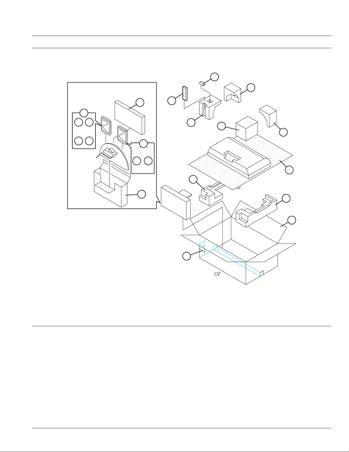
REMOTE CONTROL UNIT PARTS LIST (RM-C1816S-2C)
Ref.No. Part No. Part Name Description Local
2AA070311 BATTERY COVER
PACKING [LT-26A70BJ, LT-26A70BU, LT-26A70SJ, LT-26A70SU]
5
3
8
9 10
11 12
STAND ASS'Y
7
13
14 15
16
6
3
3
3
4
3
3
1
2
FRONT
PACKING PARTS LIST [LT-26A70BJ, LT-26A70BU, LT-26A70SJ, LT-26A70SU]
Ref.No. Part No. Part Name Description Local
1 GA10002-095A-U PACKING CASE
2 GA10180-081A-U EURO LABEL LT-26A70BJ
2 GA10180-078A-U EURO LABEL LT-26A70BU
2 GA10180-080A-U EURO LABEL LT-26A70SJ
2 GA10180-076A-U EURO LABEL LT-26A70SU
3 GA10162-002B-U CUSHION ASSY 6pcs in 1set LT-26A70BJ,LT-26A70SJ
3 GA10162-002A-U CUSHION ASSY 6pcs in 1set LT-26A70BU,LT-26A70SU
4 GA10165-001A-U FOAM SHEET
5 ------------ BATTERY R6P/AA(x2)
6 RM-C1816S-2C REMOTE CONTROL UNIT
7 GA30118-001A-U SPACER PAD
8 GA30007-001A-U DOCUMENT BAGS
9 LCT1504-001A-U CAUTION SHEET LT-26A70BJ,LT-26A70SJ
9 LCT1504-002A-U CAUTION SHEET LT-26A70BU,LT-26A70SU
10 ------------ WARRANTY CARD BT-54030-1
11 LCT2174-001A-U INST BOOK English LT-26A70BJ,LT-26A70SJ
11 LCT2175-001A-U INST BOOK English/French/German/Spanish/Dutch /Italian/Portuguese LT-26A70BU,LT-26A70SU
12 GA30011-001A-U REGISTRATION CARD LT-26A70BJ,LT-26A70SJ
13 GA30007-001A-U DOCUMENT BAGS LT-26A70BU,LT-26A70SU
14 LCT2176-001A-U INST BOOK Swedish/Finn/Danish/Norwegian LT-26A70BU,LT-26A70SU
15 LCT2177-001A-U INST BOOK Russian/Romanian/Hungarian/Czech/Bulgarian/Polish/Ukrainian LT-26A70BU,LT-26A70SU
16 GA30119-001A-U STAND BOX
(No.YA492)3-17
Page 40

PACKING [LT-32A70BJ, LT-32A70BU, LT-32A70GU, LT-32A70SJ, LT-32A70SU]
7
5
STAND ASS'Y
3
6
8 9 10 11
12
13 14
3
3
4
3
3
2
FRONT
1
PACKING PARTS LIST [LT-32A70BJ, LT-32A70BU, LT-32A70GU, LT-32A70SJ, LT-32A70SU]
Ref.No. Part No. Part Name Description Local
1 GA10002-087B-U PACKING CASE
2 GA10180-087A-U EURO LABEL LT-32A70BJ
2 GA10180-084A-U EURO LABEL LT-32A70BU
2 GA10272-074A-U EURO LABEL LT-32A70GU
2 GA10180-086A-U EURO LABEL LT-32A70SJ
2 GA10180-082A-U EURO LABEL LT-32A70SU
3 GA10273-002B-U CUSHION ASSY 5pcs in 1set LT-32A70BJ,LT-32A70GU,LT-32A70SJ
3 GA10273-002A-U CUSHION ASSY 5pcs in 1set LT-32A70BU,LT-32A70SU
4 GA10165-002A-U FOAM SHEET
5 ------------ BATTERY R6P/AA(x2)
6 RM-C1816S-2C REMOTE CONTROL UNIT
7 GA30007-001A-U DOCUMENT BAGS
8 LCT1504-001A-U CAUTION SHEET LT-32A70BJ,LT-32A70SJ
8 LCT1504-002A-U CAUTION SHEET LT-32A70BU,LT-32A70GU,LT-32A70SU
9 ------------ WARRANTY CARD BT-54030-1
10 LCT2174-001A-U INST BOOK English LT-32A70BJ,LT-32A70SJ
10 LCT2175-001A-U INST BOOK English/French/German/Spanish/Dutch /Italian/Portuguese LT-32A70BU,LT-32A70SU
11 GA30011-001A-U REGISTRATION CARD LT-32A70BJ,LT-32A70SJ
12 GA30007-001A-U DOCUMENT BAGS LT-32A70BU,LT-32A70GU,LT-32A70SU
13 LCT2176-001A-U INST BOOK Swedish/Finn/Danish/Norwegian LT-32A70BU,LT-32A70GU,LT-32A70SU
14 LCT2177-001A-U INST BOOK Russian/Romanian/Hungarian/Czech/Bulgarian/Polish/Ukrainian LT-32A70BU,LT-32A70GU,LT-32A70SU
3-18(No.YA492)
Page 41

SCHEMATIC DIAGRAMS
WIDE LCD PANEL TELEVISION
LT-26A70BJ, LT-26A70BU, LT-26A70SJ,
LT-26A70SU, LT-32A70BJ, LT-32A70BU,
LT-32A70GU, LT-32A70SJ, LT-32A70SU
CD-ROM No.SML200611
BASIC CHASSIS
FT2
COPYRIGHT © 2006 Victor Company of Japan, Limited.
No.YA492
2006/11
Page 42

LT-26A70BJ, LT-26A70BU, LT-26A70SJ, LT-26A70SU, LT-32A70BJ
LT-32A70BU
,
LT-32A70GU, LT-32A70SJ, LT-32A70SU
STANDARD CIRCUIT DIAGRAM
NOTE ON USING CIRCUIT DIAGRAMS
1.SAFETY
The components identified by the symbol and shading are
critical for safety. For continued safety replace safety ciritical
components only with manufactures recommended parts.
2.SPECIFIED VOLTAGE AND WAVEFORM VALUES
The voltage and waveform values have been measured under the
following conditions.
(1)Input signal : Colour bar signal
(2)Setting positions of
each knob/button and
variable resistor
(3)Internal resistance of tester
(4)Oscilloscope sweeping time
(5)Voltage values
Since the voltage values of signal circuit vary to some extent
according to adjustments, use them as reference values.
: Original setting position
when shipped
: DC 20kΩ/V
: H
: V
: Othters
: All DC voltage values
20µs / div
5ms / div
Sweeping time is
specified
3.INDICATION OF PARTS SYMBOL [EXAMPLE]
In the PW board
: R1209
R209
Type
No indication
MM
PP
MPP
MF
TF
BP
TAN
(3)Coils
No unit
Others
(4)Power Supply
Respective voltage values are indicated
(5)Test point
: Test point
(6)Connecting method
: Ceramic capacitor
: Metalized mylar capacitor
: Polypropylene capacitor
: Metalized polypropylene capacitor
: Metalized film capacitor
: Thin film capacitor
: Bipolar electrolytic capacitor
: Tantalum capacitor
: [µH]
: As specified
: B1
: 9V
: Only test point display
: Connector
: Receptacle
: Wrapping or soldering
: B2 (12V
: 5V
)
4.INDICATIONS ON THE CIRCUIT DIAGRAM
(1)Resistors
Resistance value
No unit : [Ω]
K
M
Rated allowable power
No indication : 1/16 [W]
Others : As specified
Type
No indication
OMR
MFR
MPR
UNFR
FR
Composition resistor 1/2 [W] is specified as 1/2S or Comp.
(2)Capacitors
Capacitance value
1 or higher : [pF]
less than 1
Withstand voltage
No indication : DC50[V]
Others : DC withstand voltage [V]
AC indicated
Electrolytic Capacitors
47/50[Example]: Capacitance value [µF]/withstand voltage[V]
: [kΩ]
: [MΩ]
: Carbon resistor
: Oxide metal film resistor
: Metal film resistor
: Metal plate resistor
: Uninflammable resistor
: Fusible resistor
: [µF]
: AC withstand voltage [V]
(7)Ground symbol
: LIVE side ground
: ISOLATED(NEUTRAL) side ground
: EARTH ground
: DIGITAL ground
5.NOTE FOR REPAIRING SERVICE
This model's power circuit is partly different in the GND. The
difference of the GND is shown by the LIVE : ( ) side GND and the
ISOLATED(NEUTRAL) : ( ) side GND. Therefore, care must be
taken for the following points.
(1)Do not touch the LIVE side GND or the LIVE side GND and the
ISOLATED(NEUTRAL) side GND simultaneously. if the above
caution is not respected, an electric shock may be caused.
Therefore, make sure that the power cord is surely removed from
the receptacle when, for example, the chassis is pulled out.
(2)Do not short between the LIVE side GND and ISOLATED(NEUTRAL
side GND or never measure with a measuring apparatus measure
with a measuring apparatus ( oscilloscope, etc.) the LIVE side GND
and ISOLATED(NEUTRAL) side GND at the same time.
If the above precaution is not respected, a fuse or any parts will be broken.
Since the circuit diagram is a standard one, the circuit and
circuit constants may be subject to change for improvement
without any notice.
NOTE
Due improvement in performance, some part numbers show
in the circuit diagram may not agree with those indicated in
the part list.
When ordering parts, please use the numbers that appear
in the Parts List.
(No.YA492)2-1
)
Page 43

CONTENTS
SEMICONDUCTOR SHAPES ......................................................................2-2
WIRING DIAGRAM ........................................................................................2-3
BLOCK DIAGRAM ........................................................................................ 2-5
CIRCUIT DIAGRAMS .................................................................................... 2-7
MAIN PWB CIRCUIT DIAGRAM ................................................................................................................ 2-7
POWER PWB CIRCUIT DIAGRAM .......................................................................................................... 2-15
CONTROL PWB CIRCUIT DIAGRAM ...................................................................................................... 2-17
IR PWB CIRCUIT DIAGRAM .................................................................................................................... 2-18
PATTERN DIAGRAMS .............................................................................. 2-19
MAIN PWB PATTERN .............................................................................................................................. 2-19
POWER PWB PATTERN .......................................................................................................................... 2-23
CONTROL PWB PATTERN ...................................................................................................................... 2-24
IR PWB PATTERN .................................................................................................................................... 2-24
VOLTAGE CHARTS .................................................................................. 2-25
WAVEFORMS ............................................................................................ 2-26
USING P.W. BOARD
PWB ASS'Y name LT-26A70BJ LT-26A70BU LT-26A70SJ LT-26A70SU
MAIN P.W. BOARD SFT-1051A-U2
CONTROL P.W. BOARD SFT-7251A-U2
IR P.W. BOARD SFT-8951A-U2
POWER P.W. BOARD SFT-9051A-U2
PWB ASS'Y name LT-32A70BJ LT-32A70BU LT-32A70GU LT-32A70SJ LT-32A70SU
MAIN P.W. BOARD SFT-1052A-U2
CONTROL P.W. BOARD SFT-7251A-U2
IR P.W. BOARD SFT-8951A-U2
POWER P.W. BOARD SFT-9051A-U2
㸠㸠㸠
㸠㸠㸠
㸠㸠㸠
㸠㸠㸠
㸠㸠㸠
㸠㸠㸠㸠
㸠㸠㸠㸠
㸠㸠㸠㸠
SFT-1052A-U2
SEMICONDUCTOR SHAPES
TRANSISTOR
BOTTOM VIEW FRONT VIEW TOP VIEW
CHIP TR
E
C
B
ECB
IC
BOTTOM VIEW FRONT VIEW TOP VIEW
OUT
E
IN
IN OUTE
B
(G)E(S)C(D)
1 N
ECB
ECB
1
1 N
C
BE
N
CHIP IC
2-2(No.YA492)
TOP VIEW
N
N
N
1
N
1
N
Page 44

WIRING DIAGRAM
LCD PANEL UNIT
[INVERTER PWB:CN1]
TOP
LCD PANEL UNIT
[CONTROL PWB: J1]
TOP
TOP
1
W
4
1
10
P
1
A
9
1
F
7
9131
1
CN00F
7
CN00R
1
1
CN00U
4
7
1
CN0LR
5
1
CN0LV2CN00A
U/V TUNER
7
1
R
CONTROL
PWB
TOP
F9001 250V/6.3A
1
POWER CORD
IR PWB
MAIN PWB
2
PW
SPEAKER (L) SPEAKER (R)
POWER PWB
14
U
2-4(No.YA492)(No.YA492)2-3
Page 45

BLOCK DIAGRAM
EXT-1
V1_IN
VTV_OUT
YS_IN
R_IN
G_IN
B_IN
L1/R1_IN
LTV/RTV_OUT
EXT-2
V2/Y2_IN
VSEL_OUT
YS_IN
R_IN
G_IN
B_IN
L2/R2_IN
LSEL/RSEL_OUT
MAIN PWB
TU1
U/V
TUNER
SC1_CVBS_IN
SC1_CVBS_OUT
㪪㪚㪈㪶㪝㪙
SC2_R,G,B
SC1_AL/AR_IN
SC1_AL/AR_OUT
SC2_CVBS_IN
SC2_CVBS_OUT
㪪㪚㪉㪶㪝㪙
SC2_R,G,B
SC2_AL/AR_IN
SC2_AL/AR_OUT
TU_CVBS
AUDIO OUT
SIF OUT
IC9
RGB
SW
SC_R
SC_G
SC_B
CVBS1
Y_G3
CVBS_OUT1
FB1
PB_B3
CVBS_OUT2
PR_R2
Y_G2
PB_B2
FB2
Y_G1
/PR_R1
/PB_B1
IC1
VIDEO
SIGNAL
SELECT
&
DSP
IC2
SDRAM
IC8
EEP
ROM
(for HDMI)
IC3
MICOM
(CPU)
LCD PANEL
IC7
㪜㪜㪧
ROM
(SETTING
DATA)
IC5
FLASH
ROM
HDMI CONN.
DIGITAL IN
Y
Pb
Pr
V
EXT-3
L/R
AC220-240V
50Hz
Y/PUB/PR_IN
CVBS_IN
AVL/AVR_IN
F9001
LF9001
LF9002
LF9003
L9001
POWER PWB
D9001
CP9506
CP
T9501
T9202
VOLTAGE
FEED BACK
IC9501
PC9501
PC9502
PC9202
VOLTAGE
FEED BACK
CP9501
CP
CP9503
CP9504
CP
CP9005
CP
Q9505
SW
LB_PRO
Q9503
SW
LB_PRO
RGB_RX
PR_R3
AU_
+13.5V
24V
14V
BT_32V
STB-5V
/STB-3.3V
IC11
AUDIO
SIGNAL
SELECT
&
DSP
HDMI_AL_IN
/HDMI_AR_IN
SP_L/R LN,LP/RN,RP
HP_L/R
IC21
D-A
CONV.
IC13
HP AMP
IC601
POWER
AMP
PWR_LED
RMT
KEY1,2
S7001-S7007
㪡㪎㪇㪇㪈
CONTROL PWB
IR PWB
㪠㪚㪏㪇㪇㪈
D8001
POWER
LED
IR
RECEIVE
SPEAKER
(Lch)
SPEAKER
(Rch)
HEADPHONE
(No.YA492)2-5 2-6(No.YA492)
Page 46

CIRCUIT DIAGRAMS
MAIN PWB CIRCUIT DIAGRAM (1/4) SHEET1
MAIN PWB ASS'Y(1/4)
SFT-1051A-U2 [LT-26A70BJ, LT-26A70BU, LT-26A70SJ, LT-26A70SU]
SFT-1052A-U2 [LT-32A70BJ, LT-32A70BU, LT-32A70GU, LT-32A70SJ, LT-32A70SU]
SHEET 3
SHEET 3
SHEET 4
SHEET 3
SHEET 3,4
SHEET 3,4
SHEET 2,3,4
TU_AGC
TU_AFT
TU_CVBS
RESET_L
SP_VCC
C625
.1/25
C603
1/16
C604 C606
1/16 1/16
100K
R609
SP.GNDSP.GND
R607
100K
R328
47k
Q38
C146
1/10
IC13
C147
1/10
POWER AMP
C605
1/16
GND
C626
IC601
SP.GND
GND
100K
R610
SP.GND
Y603Y602Y601
OPENOPENOPEN
SP.GND
R327
0
C338
1/10
C337
47/16
GND
TU U/V TUNER1
GND
R27
C253
TU_AGC
TU_AFT
TU_CVBS
SCL3
SDA3
SCL5
SDA5
100k
OPEN
OPEN
R8
C200
220k
GND
5V0
L39
C149 C130
5V0
Q17
C88
.1/16
.1/16
R297
820
SCL3
SDA3
NPN
GND
C92
GND
R37
OPEN
R296
GND
0
C305
OPEN
C254
R309
GND
.01/16
GND
R238
100
C256
.01/16
8V0
R240
0
R312 R314
2.2k 680
JP3
OPEN
R90 R310
1k 330
GND
OPEN
C8
GND GND
100
R235
R293
100k
OPEN
C7
R308
100k OPEN
100
GND
R236
C304 C291 L38
R94
820p 47p
1k
Q27
NPN
C289
.01/16
L37
R140
4.7k
BT32V
OPEN
0.1
D57
C87
R311
C94
GND
R313 R316
2.2k 270
JP1
OPEN
Q28
NPN
R326
180
JP2
OPEN
C343
OPEN
47p
C292
Q7
Q6
R317
47
270
18p
1k
R95
C252
R315
5V0_SB3V3_SB
R211
4.7k
5V0_SB3V3_SB
R213R139
4.7k4.7k
Q26
NPN
C290 R292
.01/16 1k
RESET_L
SDA5
SCL5
5V0
R59
10
R237
100
Q18
NPN
R239
100
R82
1k
C203
C255
.01/16
SIF
RESET_L
SCL5
SDA5
SCL5
SDA5
SCL5
SDA5
C91
.1/16
C257
47p
C258
47p
C259
1p
C260
1p
X3
GND
R83
1k
GND
GND
GND
GND
GND
GND
C150
100/16
C89
.1/16
C183
4700p
5V0
L16
R20
100
R138
4.7k
R241
100
C261
33p
R242
100
C262
33p
GND
GND
TP1
OPEN
GND GND
FB50
SP.GND
FB40
SP.GND
FB46
SP.GND
FB10
SP.GND
FB39
SP.GND
C202
C133
.01/16
TP2
OPEN
FB61
GND
FB62
GND
FB63
GND
FB64
GND
FB65
GND
AVL_IN
AVR_IN
SC2_AL_IN
SC2_AR_IN
SC1_AL_IN
SC1_AR_IN
IC11
AUDIO
SIGNAL
SELECT
&
DSP
L15 C131 C235
.01/16 47/16
5V0
GND
SP.GND
SP.GND
SP.GND
SP.GND
SP.GND
GND
HDMI_AL_IN
HDMI_AR_IN
R601
1K
R602
1K
33K
33K
100p
5V0_SB
R603
R604
C602
R621R619
OPENOPEN
R622
OPEN
Q608
OPEN
R626
56k
SC1_AL_OUT
SC1_AR_OUT
SC2_AL_OUT
SC2_AR_OUT
Q607
PNP
SP_L
SP_R
HP_L
HP_R
HP_SW
Q609
OPEN
GND
GND
D602
5V0
D302
C342R331
100/16100k
HP_SW
HP_R
HP_L
D605
R620
OPEN
OPEN
D606
OPEN
5V0
8V0
Y607
Y608
0
OPEN
D601
R616
100k
C627
GND
SP_R
SP_L
8V0
100
100
100
100
C266
C240
C241
C265
C264
C263
C206
3900p
1/16
1/16
3900p
6800p
6800p
L17
C190 C204
1000p 10/16
C205
10/16
C231
330p10/16
C229
330p
C230
330p
C228
330p
C132
.01/16
C201
R248
R247
R246
R245
C90
.1/16
GND
100p
C601
R605
GNDGNDGND
OPEN
Q610
OPEN
R623 R617
OPEN OPEN
GND
D603
R614
2.7k
D604
R344
56k
GND
D301
Q602Q601
OPENOPEN
R606
SP.GND
OPEN
Q606
OPEN
R613
12k
GND
R615
2.7k
Q39
PNP
D303
R284
0
R285
0
R618
10k
Q604
NPN
Q603
NPN
Q605
NPN
R249 Q37
4.7k PNP
R54
OPEN
R55
OPEN
R608
100K
5V0_SB
R612
100K
GND
GND
R330
0
R329
100k
C339
.0022
C340
GND
.0022
C624
0.22
IC601
100K
0.01
1/16
C609
.22/16
C607
C608
R611
SP.GND
.1/50
.1/50
.1/50
C753
C758
C754
5V0
C152
HP AMP
C238
100/16
C151
L603
C621
.22
C622
0.33
SP.GND
L604
C623
0.22
C610
.22/16
L601
C611
.33/25
L602
.1/50
.1/50
.1/50
.1/50
.1/50
.1/50
C755
C756
C757
C759
C760
C761
R303
22
R89
1k
C273
.1/50
GND
R88
1k
C272
.1/50
R302
22
C620
.22
SP.GND
SP_VCC
C619
1/25
C617
1/16
SP_VCC
SP.GND
SP_VCC
.1/50
C762
GND
FB22
FB36
FB37
FB23
FB24
Y613
Y614
0
0
C618
C616
1/16
SP.GND
C615
C614
1/25
Y611 Y612
C612
.22/16
C613
.22/16
SP.GND
C302
100p
GND
00
C303
100p
GND
GND
C301
100p
GND
KEYA
KEYB
HP_DET
CN0LR
CN00R
S_PWR
S_MUTE
A_MUTE
KEYA
KEYB
HP_DET
SPEAKER
SHEET 3
SHEET 2,3
CONTROL PWB
CN70R
SHEET 6
SHEET 3
SC2_AL_OUT
SC2_AR_OUT
SC1_AL_OUT
SC1_AR_OUT
AVL_IN
AVR_IN
SC2_AL_IN
SC2_AR_IN
AVL_IN
AVR_IN
SC1_AR_OUT
SC1_AL_OUT
SC2_AL_IN
SC2_AR_OUT
SC2_AL_OUT
SHEET 2 SHEET 4
2-8(No.YA492)(No.YA492)2-7
SC1_AL_IN
SC2_AR_IN
SC1_AR_IN
SC1_AL_IN
SC1_AR_IN
HDMI_AL_IN
HDMI_AR_IN
HDMI_AL_IN
HDMI_AR_IN
c10496001a001_1106_1/4_0.0
Page 47

MAIN PWB CIRCUIT DIAGRAM (2/4) SHEET 2
SHEET 1 SHEET 1,3
MAIN PWB ASS'Y(2/4)
SFT-1051A-U2 [LT-26A70BJ, LT-26A70BU, LT-26A70SJ, LT-26A70SU]
OPEN
SC1_AL_IN
SC2_AL_IN
SC2_AR_IN
SC1_AR_OUT
SC1_AL_OUT
SC2_AR_OUT
Q40
OPEN
R278
OPEN
Q29
R160 R161
1k OPEN
SC1_AL_OUT
SC1_AR_OUT
SC2_AL_OUT
SC2_AR_OUT
SC2_AL_OUT
AVR_IN
AVL_IN
D61D62
OPENOPEN
C341
OPEN
GND
D44
R42
OPEN
R152
OPEN
R163
47k
Q8
C86 C246
100p .1/16
GND
D47 D48 D49
OPEN OPEN OPEN
AVR_IN
HDMI_5V0
AVL_IN
A_MUTE
A_MUTE
5V0
Y40
OPEN
PX_VD_3V3
R159
4.7k
D50
R154 R155
OPEN OPEN
CECIN
PX_VD_3V3
GND
R91
OPEN
R156
OPEN
SC1_AR_IN
SC1_FB
SC1_R
SC1_G
SC1_ID
SC1_AL_IN
SC1_AR_IN
A.MUTE
SC2_FB
SC2_R
SDA_LINK
SC2_G
SCL_LINK
SC2_ID
SC2_B
SC2_AL_IN
SC2_AL_OUT
SC2_AR_IN
A.MUTE
AVR_IN
AVL_IN
PR_IN
PB_IN
CVBS_IN
RXCLK-
RXCLK+
B_RX0-
G_RX1-
R_RX2-
R_RX2+
SC1_AR_IN
SC1_AL_IN
SC2_AR_IN
SC2_AL_IN
D63
A.MUTE
R276
OPEN
Y_IN
D30
100
D25
PX_VD_3V3
SC1_CVBS_IN
R169
10k
SC1_CVBS_OUT
C249
R167
10k
SC1_AL_OUT
SC1_AR_OUT
SC2_CVBS_IN
R170
10k
SC2_CVBS_OUT
C250
R168
10k
SC2_AR_OUT
B_RX0+
G_RX1+
L18
C64
J1
R260
R263 R69
R264
R265
L20
C208 C207
L21
FB54
R332
82k
GND
J1
D16
R269
R270
L24
C217
L25
C219
R339
FB55
R338
82k
GND
J3
J3
J3
J5
D33
OPEN
R261 C215
75 470p0OPEN
75
D8
75
75
75
470p .01
R337
R336
390
R335
82k
470p
R334R333
GND
470390
Q32
Q31
R267 C221
R266
390
GND
75 470p0OPEN
75
75
75
R271
470p
GND
R342 R343
390 470
R341
82k
470p
GND
Q35
Q34
L27
GND
L28
GND
C225 C213
OPEN 10p
GND
L29
OPEN
C227
OPEN
Y29
0
GND
L30
OPEN
C226 C223
Y30
OPEN 10p
0
L31
OPEN
Y31
0
L32
0
GND
GND
GND
R282
8.2k
470
75
R340
470
D38 D39 D40 D41
OPEN OPEN OPEN OPEN
.1/16
C211
C323
OPEN
R262
75
R18
C140
1k
R70
1k
C141
1/16
R43
C135
1k
OPEN
1k 1/16
R72 C 142
R73 C136
1k 1/16
GND
D27
L22
R71
GND
D26C210
L19
C209
.01
R171
0
Q33
PNP
R172
100k
L36
C65
.1/16
C220
C326
R268
R76 C143
R77
R44
R283
R79 C145
R80 C139
OPEN
75
R19
1k 1/16
D20
C324
OPEN
1k
1k
8.2k
1k 1/16
1k 1/16
C325
C216
.01
L26
R78 C138
1k
GND
L23
C218
.01
R173
0
Q36
PNP
R174
100k
C214
470p
R75 C198
1k 1/16
C212
470p
R74 C199
1k 1/16
R273
75
GND
C222
R274 D3
10p
75
GND
R275 D4
75
GND GND
R272
C224
75
470p
D35D34 D 36 D37
OPENOPEN OPEN OPEN
10k
GND
D9
10k
1/16
D12
D13
GND
C108
C137
1/16
D17
C233
GND
C144
1/16
D21
OPEN
1/16
D24
GND
GND
GND
GND
GNDGND GND
8V0
C76
.1/16
Q9
C232
R323
10k
D11
OPEN
GND
GND
D18
R324
10k
D19
GND
GND
GND
D7
D6
C69
C68
C67
C66
NPN
R286
D10
330
C294
OPEN
GND
GND
D15
C195
10/161k
C194
10/16
D14
8V0
C75
.1/16
Q10
NPN
R287
330
C295
OPEN
D28
R231
100
R232
D29
GND
D31
C197
10/16
D23
C196
10/16
D22
D2
.1/16
.1/16
.1/16
.1/16
D5
R153
OPEN
SFT-1052A-U2 [LT-32A70BJ, LT-32A70BU, LT-32A70GU, LT-32A70SJ, LT-32A70SU]
R36
0
RX_DSDA_1
RX_DSCL_1
5V0
L14
C234C70
47/16.1/16
R62
4.7k
IC9
RGB
SW
SC1_R
5V0
D43
C85R134R135
.1/16OPENOPEN
IC8
R165
EEP
10k
ROM
PX_VD_3V3
R164
10k
Q2
Q3
PX_VD_3V3
Q5
RX_DSDA
470p
100k
C322
R124
SC1_G
R137 R136
470k 470k
Q4
RX_DSCL
R66
75
SC1_B
R35
0
EDID_WP
HDMI_DET
SC2_R
R106
75
75
R123
R61
4.7k
GND
SC2_G
SC2_B
5V0_SB
C245
C239
.1/16
1/16
R51
10k
R133
4.7k
R81
1k
OPEN
OPEN
OPEN
OPEN
C798
C799
C800
C801
C71
C72
C73
C74
R45
100
Q22
PNP
Q16
NPN
R53R290 R49
10k1.5k 10k
R52
10k
Q14
NPN
HDMI_5V0
GND
.1/16
.1/16
.1/16
.1/16
R289
27K
D42
Q15
NPN
Q13
NPN
R50
10k
R223
OPEN
D51
OPEN
C83
OPEN
GND
SC_C
SC_R
SC_G
SC_B
SC_RGB_CNTL
SDA5
SDA5
T-V_LINK_CNTL
T-V_LINKOUT
T-V_LINKIN
SCL5
T-V_LINK_CNTL
T-V_LINKOUT
T-V_LINKIN
RX_DSDA
RX_DSCL
SDA5
SCL5
HDMI_PRO
EDID_WP
HDMI_DET
CECIN
SC_RGB_CNTL
SC_C
SC_R
SC_G
SC_B
SC1_CVBS_IN
SC1_CVBS_OUT
SC1_FB
SC1_ID
SC2_CVBS_IN
SC2_CVBS_OUT
SC2_FB
SC2_ID
PR_IN
PB_IN
Y_IN
CVBS_IN
RXCLK-
RXCLK+
B_RX0-
B_RX0+
G_RX1-
G_RX1+
R_RX2-
R_RX2+
SDA_LINK
SCL_LINK
Q11
R233
NPN
100
R288
220
D32
5V0
D52
OPEN
C84
OPEN
C82
OPEN
Q12
R234
NPN
100
R47
10k
R40
OPEN
C247
OPEN
5V0_SB
R46
10k
R48
10k
Q21
GND
R157
OPEN
HDMI_PRO
SCL5
T-V_LINK_CNTL
T-V_LINKOUT
T-V_LINKIN
RX_DSDA
RX_DSCL
HDMI_PRO
EDID_WP
HDMI_DET
CECIN
SC_RGB_CNTL
SC_C
SC_R
SC_G
SC_B
SC1_CVBS_IN
SC1_CVBS_OUT
SC1_FB
SC1_ID
SC2_CVBS_IN
SC2_CVBS_OUT
SC2_FB
SC2_ID
PR_IN
PB_IN
Y_IN
CVBS_IN
RXCLK-
RXCLK+
B_RX0-
B_RX0+
G_RX1-
G_RX1+
R_RX2-
R_RX2+
SHEET 1,3,4
SHEET 3
SHEET 4
SHEET 3
SHEET 4
NOTE : Refer to the part list for the part number of IC8.
c10496001a002_1106_2/4_0.0
(No.YA492)2-9 2-10(No.YA492)
Page 48

MAIN PWB CIRCUIT DIAGRAM (3/4) SHEET 3
FB9
OPEN
FB31
*1
FB41
*1
FB42
OPEN
FB38
*1
FB26
FB27
FB28
FB33
FB29
FB30
FB34
SP.GND
*1
*1
*1
IC19IC16IC17
C105
.33
C96
.33
IC17 IC16 IC19
C97
.33
24V 12V
SP_VCC
C315
5V0_SB
GND
FB18
R175
OPEN
PX_VD_3V3
GND
R176
C334
470p
PX_HDMI_3V3
GND
R177
C335
OPEN
470p
POWER PWB
CN900A
SHEET 5
POWER PWB
CN900F
SHEET 5
SHEET 1,2
SHEET 1
SHEET 4
SHEET 2
SHEET 1
IR PWB
SHEET 7
T-V_LINK_CNTL
CN80U
T-V_LINKIN
EDID_WP
T-V_LINKOUT
SC_RGB_CNTL
HDMI_PRO
A_MUTE
S_PWR
CECIN
TU_AGC
TU_AFT
HP_DET
CN00A
CN00F
GND
SCDT
KEYA
KEYB
CN00U
GND
C298 C299 C300
100p 100p 100p
5V0_SB
C274
1/10
5V0
FB15
C275
1/10
5V0
FB14
C276
1/10
FB19
FB20
FB21
C277
22/16
C278
22/16
C279
22/16
GND
3V3_SB
MAIN PWB ASS'Y(3/4)
SHEET 4
uP_A3
uP_A2
uP_A1
8051_AD3
4.7k
R113
8051_AD3
8051_AD4
3V3_SB
4.7k
R132
8051_AD4
8051_AD5
OPEN
R7
CNVSS
8051_AD5
8051_AD6
D58
8051_AD6
8051_AD7
GNDGND
8051_AD7
uP_A0
0
R17
15p
C185
GND
C59
.1/16
IC
MICOM
(CPU)
uP_A1
3
GND
C193
uP_A0
uP_A0
uP_A2
15p
C184
GND GND
uP_A1
3V3_SB
L40
uP_A2
uP_A3
uP_A4
uP_A3
X2
.1/16
C332
8051_CS2PX
8051_AD2
8051_AD1
8051_AD0
8051_RD#
8051_ALE
8051_WR#
PX_VD_3V3
R147
R294
3.3k
OPEN
C314
R101
OPEN
OPEN
R291
OPEN
Q41
OPEN
C248
.1/16
5V0_SB
BT32V
IC18
5V0
R279
10k
FB16
C293
C280
1/16
47/6.3
FB12
*1
R277
5.6k
IC15
IC15
C282
1/10
C100
C287
.33
22/16
5V0
FB52
C281
C236
.1/16
GND
C725
OPEN
C296
470p
IC14
IC14
C93 C237C95
OPEN 5600pOPEN
C731
OPEN
C727
OPEN
C726
OPEN
GND
47/6.3
47/6.3
C251
1/16
GND
GND
47/6.3
R253
OPEN
C285
.01/16
D45
R39
3.9k
C732
C734
C736
C738
OPEN
OPEN
OPEN
OPEN
C733
C735
C737
C739
OPEN
OPEN
OPEN
OPEN
BT32V
C794
C729
OPEN
OPEN
C728
C730
GND
OPEN
OPEN
R322
0
BKLT_PWR
R295
OPEN
C102
C284
.1/16
GND
C103
C283
.1/16
FB32
C99
C286
.1/16
FB45
GND
C98
.1/16
L33
R64
8.2k
R65
1.5k
GND
R38
10k
5V0 12V
C740
OPEN
C741
GND
OPEN
3V3_SB
C795
OPEN
C796
C797
GND
OPEN
OPEN
BKLT_CNTL
POWER
LB_PRO
T-V_LINKIN
EDID_WP
T-V_LINK_CNTL
T-V_LINKOUT
SC_RGB_CNTL
HDMI_PRO
FB43
FB44
PX_VDDMQ
C714
C715
OPEN
OPEN
C713
OPEN
C712
C711C336 C104
OPEN
OPEN470p .1/16
PX_VA_1V8
PX_VL_1V8
C780
C782
C784
OPEN
OPEN
OPEN
C779
OPEN
C781
C783
OPEN
OPEN
PX_VD_1V8
C708
OPEN
C707
C709
OPEN
OPEN
C101
C743
C745
OPEN
OPEN
C742
C744
C747
OPEN
OPEN
OPEN
C717
OPEN
C716
C718
OPEN
OPEN
A_MUTE
S_PWR
SCDT
CECIN
KEYA
KEYB
TU_AGC
TU_AFT
HP_DET
LED_ON
PX_VDDM
GND
GND
C748
OPEN
C719
OPEN
C785
OPEN
C710
OPEN
IR
C749
OPEN
C720
OPEN
T-V_LINKIN
EDID_WP
T-V_LINK_CNTL
T-V_LINKOUT
SCDT
TU_AGC
TU_AFT
LB_PRO
HDMI_PRO
KEYA
KEYB
A_MUTE
BKLT_PWR
E_PAGE
PNL_PWR
POWER
SC_RGB_CNTL
S_PWR
HP_DET
CPU_RESET
C750
OPEN
C751
OPEN
C721
OPEN
C722
OPEN
uP_AD7
uP_AD6
3V3_SB
3V3_SB
SP.GND
uP_AD5
uP_AD4
uP_AD3
uP_AD2
uP_AD1
uP_AD0
R200
R199
R198
R197
R319
R191
R204
R205
R122
R207
R208
R196
R195
R194
GND
100
100
3V3_SB
100
100
100
100
100
IC6
C330 C319
PX_VA_1V8
C62
.1/16
GND
C746
OPEN
R105 R104
3.3k 3.3k
C191
C752
OPEN
GND
5V0_SB
C723
OPEN
C724
GND
OPEN
8051_ALE
R6
100
100
R203
100
R202
100
R201
100
100
100
100
0
4.7k
100
100
OPEN
4.7k
4.7k
4.7k
R107
R193
R109
R110
C60
100k.1/16
.1
C13 C328C316
OPEN 5600pOPEN
8051_CS2PX
3V3_SB
8051_RD#
C321
.01/16
IC22
IC22
8051_WR#
D1R259
8051_AD0
4.7k
R103
3V3_SB
8051_AD1
4.7k
R102
8051_AD2
4.7k
R125
R10
0
R219
3.9k
SFT-1051A-U2 [LT-26A70BJ, LT-26A70BU, LT-26A70SJ, LT-26A70SU]
SFT-1052A-U2 [LT-32A70BJ, LT-32A70BU, LT-32A70GU, LT-32A70SJ, LT-32A70SU]
uP_A7
uP_A6
uP_A5
uP_A4
uP_A4
uP_A5
uP_A6
uP_A7
3V3_SB
IC
R255
33
R16
0
0
0
4.7k
4.7k
R128
R127
C189
.1/16
C153 C106
100/16 .1/16
OPEN
D73
D65
D66
OPEN
D69
3V3_SB
4.7k
R126
5
FLASH ROM
IC20
GND
OPEN
D72
OPEN
D67
IC
EEP
ROM
(SETTING DATA)
R96
OPEN
D71
OPEN
D68
7
C57
IC4
OPEN
OPEN
GND
R151
R150
22
22
5V0_SB
RX
GND
TX
R32
OPEN
GND
GND
C6
OPEN
LCD_VCC
C333
RESET_L
RESET_H
CN4R14
OPEN0
CECIN
CNVSS
CPU_RESET
BKLT_CNTL
S_MUTE
LED_ON
PX_INT#
HDMI_DAC_MUTE
DEBUG
HDMI_DET
SDAE
SCLE
SCL3
SDA3
IR
R13
R12
SCL5
SDA5
HDMI_DAC_MUTE
RESET_H
RESET_L
PX_INT#
HDMI_DET
SDA3
SCL3
S_MUTE
SDAE
SCLE
R280
SDA3
R281
SCL3
DEBUG
CPU_RESET
E_PAGE
SDAE
SCLE
E_PAGE
OPEN
OPEN
uP_A16
uP_A158051_WR#
uP_A14
uP_A13
uP_A13
uP_A8
uP_A12
uP_A9
uP_A11
uP_A11
uP_A10
8051_RD#
uP_A9
uP_A10
uP_A20
uP_AD7
uP_AD6
uP_AD5
CPU_RESET
uP_AD4
uP_AD3
uP_A19
uP_A18
uP_A8
3V3_SB
uP_A7
uP_A6
uP_A5
R318
10k
uP_A4
uP_A3
uP_A2 uP_A1
12V
FB17
R320
R321
OPEN
OPEN
5V0_SB
5V0
D54
D60
R225
100
R224
100
C188 C187
100p 100p
PNL_PWR
RA97
OPEN
uP_A0
uP_A1
uP_A2
uP_A3
uP_A4
uP_A5
uP_A6
uP_A7
RA96
OPEN
R250
0
R209
OPEN
R148
22
R149
OPEN
R251
OPEN
R252
0
R63
47k
R226
100
R129
4.7k
R130
OPEN
R15
0
4.7k
10k
R121
R258
R162
100
C327
.01/16
IC23
IC23
C317
2700p
10k
R144
8051_CS2PX
4.7k
4.7k
R117
R119
C329C318
5600pOPEN
R220
3.9k
8051_AD0
8051_AD1
8051_AD2
8051_AD3
8051_AD4
8051_AD5
8051_AD6
8051_AD7
uP_A18
uP_A19
uP_A20
8051_ALE
3V3_SB
OPEN
OPEN
R33
R215
uP_A14
uP_A12
uP_A7
uP_A6
uP_A5
uP_A4
uP_A3
uP_A2
uP_A1
uP_A0
uP_AD0
uP_AD1
uP_AD2
8051_WR#
8051_RD#
3V3_SB
R131
4.7k
GND
OPEN
C5
OPEN
R34
R227
100
R228
100
R212
1k
R214
100
R210
100
R217
100
R120
100
R254
100
L41
D59
R218
39k
R222
5.6k
GNDGND
R29
10k
RA254
RA253
uP_A16
uP_A15
uP_A14
uP_A13
0
R256
R97
100
Q30
FB35
C331 C320
uP_A17
uP_AD7
uP_AD6
uP_AD5
uP_AD4
uP_AD3
uP_AD2
uP_AD1
uP_AD0
5V0_SB3V3_SB
R166
10k
3V3_SB
R158
4.7k
.1/16
8051_AD7
8051_AD6
8051_AD5
8051_AD4
8051_AD3
8051_AD2
8051_AD1
8051_AD0
3V3_SB
GND
C192
C61R257
.1/16
uP_A9
uP_A8
uP_A7
uP_A6
uP_A5
4.7k
R114
C63
C58
GND
D53
uP_A12
uP_A11
uP_A10
5V0
12V24V
R216
39k
R221
5.6k
R28
10k
3V3_SB
L13
uP_A17
uP_A0
uP_AD7
uP_AD6
uP_AD5
uP_AD4
C186
uP_AD3
GND
C129
.01/16
uP_AD2
uP_AD1
uP_AD0
GND
3V3_SB
R92
1k
OPEN
R93
OPEN
GND
8V0
C702
OPEN
C701
C288
SDA5
SCL5
OPEN
GND
D70
C703
OPEN
OPEN
CN2
OPEN
GND
CN001
HDMI_DAC_MUTE
RESET_H
RESET_L
PX_INT#
HDMI_DET
SDA5
SCL5
SDA3
SCL3
S_MUTE
SHEET 4
SHEET 1
SHEET 4
SHEET 2
SHEET 1,2,4
SHEET 1,4
SHEET 1
OPEN
GND
GND
NOTE : Refer to the part list for the part number of IC7.
GND
c10496001a003_1106_3/4_0.0
2-12(No.YA492)(No.YA492)2-11
Page 49

MAIN PWB CIRCUIT DIAGRAM (4/4) SHEET 4
PX_VL_1V8
PX_VA_1V8
PX_VD_3V3
PX_VDDMQ
C180
C182
4700p
4700p
C175
22/16
GND
R189
100
C128
.01/16
R190
100
GND
C124
C126
.01/16
.01/16
C123
C125
C127
C181
4700p
.01/16
PX_MCK0
PX_MA8_1
PX_DQM2_1
PX_MD21_1
PX_MD24_1
PX_MD26_1
PX_DQM3_1
PX_MD28_1
PX_MD30_1
PX_MCK0#
PX_CLKE_1
PX_DQS2_1
PX_MD20_1
PX_MD22_1
PX_MD23_1
PX_MD25_1
PX_MD27_1
PX_DQS3_1
PX_MD29_1
PX_MD31_1
DDR_VREF
.01/16
.01/16
R145
22
R146
22
FB2
C162 C35
L9
L10
L7
L8
L11
L12
*1
FB3
*1
FB6
C56
.1/16
C55
.1/16
C159
GND
C160
GND
*1
GND
C164
C165
C166
C167
C168
C169
C170
C163
PX_MA7_1
PX_MD11_1
PX_DQS1_1
GND
GND
GND
GND
GND
GND
GND
PX_MD9_1
PX_MD8_1
PX_PAVDD1
C32
.1/16
C178
PX_PAVDD2
C33
.1/16
.1/16
PX_MD6_1
PX_MD4_1
C179
PX_DQS0_1
C37
.1/16
C38
.1/16
C39
.1/16
C40
.1/16
C42
.1/16
C43
.1/16
C41
.1/16
C36
.1/16
PX_MD2_1
PX_MLF1
2700p
PX_PLF2
2700p
PX_AVDDAPLL
PX_AVDD_ADC1
PX_AVDD_ADC2GND
PX_AVDD_ADC3
PX_AVDD_ADC4
PX_AVDD3_ADC1
PX_AVDD3_ADC2
PX_AVDD3_BG_ASS
PX_AVDD3_OUTBUF
PX_MD1_1
PX_CAS#_1
PX_MD19_1
PX_CS0#_1
PX_RAS#_1
PX_MA5_1
PX_MA6_1
IC2
SD RAM
PX_DQM1_1
PX_VL_1V8
PX_MD10_1
PX_MD7_1
PX_MD5_1
*1
FB5
C161 C34
GND
PX_MD3_1
PX_MD0_1
PX_DQM0_1
PX_WE#_1
PX_VD_1V8
PX_VD_1V8
PX_MD18_1
PX_MD17_1
.1/16
PX_MA4_1
PX_MA9_1
PX_VDDMQ
R68
1K1K.1/16
R67
GND
GND
PX_AVDDLLPLL
GND
PX_AVDDAPLL
GND
SHEET 2
RXCLK-
RXCLK+
B_RX0-
RXCLK-
RXCLK+
B_RX0-
C15
C16
.1/16
GND
PX_AVCC
PX_AVDDLLPLL
C1
C2
PX_PAVDD1
PX_PAVDD2
MAIN PWB ASS'Y(4/4)
SFT-1051A-U2 [LT-26A70BJ, LT-26A70BU, LT-26A70SJ, LT-26A70SU]
B_RX0+
G_RX1-
G_RX1+
R_RX2-
R_RX2+
B_RX0+
G_RX1-
G_RX1+
R_RX2-
R_RX2+
PX_VD_1V8
GND
DDR_VREF
PX_VDDMQ
PX_PVCC
PX_REGVCC
X1R21
1M
R1
PX_MD16_1
PX_BA0_1
GND
PX_MA11
PX_MA10
PX_MA9
PX_MA8
PX_MA7
C117
.01/16
C18C19C20
.1/16.1/16.1/16
C22C23C24
.1/16.1/16.1/16
PX_MLF1
PX_PLF2
GND
PX_MA6
PX_MA5
PX_MA4
PX_MA3
PX_MA2
C17
.1/16
PX_MA1
PX_MA0
PX_CS0#
PX_RAS#
C119C118
.01/16.01/16
C120
.01/16
PX_CAS#
PX_WE#
PX_CLKE
PX_BA0
PX_BA1
RXCLK-
RXCLK+
B_RX0-
B_RX0+
G_RX1-
G_RX1+
R_RX2-
R_RX2+
C21
GND
.1/16
PX_VDDM
C53
C121
.1/16
.01/16
C54
C122
.1/16
.01/16
GND
C176
22/16
PX_MA11_1
PX_MD15_1
PX_MA1_1
PX_MA2_1
PX_MA10_1
PX_MD14_1
PX_MD13_1
PX_MD12_1
PX_MA3_1
PX_MA0_1
PX_BA1_1
SC2_CVBS_OUT
GND
C776C777C778
OPENOPENOPEN
GND
GND
GND
GND
GND
GND
GND
GND
0
GND
GND GND GND GND
C110
.01/16
C52
.1/16
PX_MD25
PX_MD26
PX_MD27
PX_MD28
PX_MD29
PX_MD30
PX_MD31
PX_DQM3
PX_DQS3
PX_MCK0
PX_MCK0#
C3
OPEN
.1/16
TU_CVBS
SC2_ID
SC1_ID
SC2_FB
SC1_FB
C9
SC1_CVBS_OUT
PX_AVDD3_OUTBUF
GNDGND
PX_AVDD3_BG_ASS
C10
GND GND
PX_AVDD3_ADC1
PX_MD15 PX_MD15_1
PX_MD13 PX_MD13_1
PX_MD11 PX_MD11_1
PX_MD9 PX_MD9_1
PX_MD31 PX_MD31_1
PX_MD29 PX_MD29_1
PX_MD27 PX_MD27_1
PX_MD25 PX_MD25_1
PX_MD7 PX_MD7_1
PX_MD5 PX_MD5_1
PX_MD3
PX_MD1 PX_MD1_1
PX_MD0
PX_MD23 PX_MD23_1
PX_MD21 PX_MD21_1
PX_MD19 PX_MD19_1
PX_MD17 PX_MD17_1
PX_MD16
.1/16
GND GND GND
(No.YA492)2-13 2-14(No.YA492)
SFT-1052A-U2 [LT-32A70BJ, LT-32A70BU, LT-32A70GU, LT-32A70SJ, LT-32A70SU]
PX_HDMI_3V3PX_AVCC
R98R99
OPENOPEN
LCD_VCC
*1
FB7
C173
22/16
GND
*1
FB8
GND
PX_REGVCC
.1/16
SCL3
10
R58
10
R57
OPEN
R31
OPEN
R30
RESET_H
PX_INT#
SCDT
SC2_CVBS_OUT
SC1_CVBS_OUT
SC2_ID
SC1_ID
SC2_FB
SC1_FB
Y_IN
SC_G
SC1_CVBS_IN
PR_IN
SC_R
CVBS_IN
SC_C
PB_IN
SC_B
SC2_CVBS_IN
RX_DSCL
RX_DSDA
TU_CVBS
L4
L2
R22
OPEN
R2
OPEN
R24
OPEN
R25
OPEN
R23
0
R56
L6
OPEN
C134
R3
0
R4
0
R5
0
C148
100/16
SCL3
SDA3
SCL5
SDA5
CN0LV2
CN0LV2
R26
OPEN
10
1/16
GND
SHEET 1,3
SDA3
SCL5
SHEET 1,2,3
SDA5
RESET_H
PX_INT#
SHEET 3
SCDT
SC2_CVBS_OUT
SC1_CVBS_OUT
SC2_ID
SC1_ID
SC2_FB
SC1_FB
Y_IN
SC_G
SC1_CVBS_IN
PR_IN
SC_R
CVBS_IN
SC_C
PB_IN
SC_B
SC2_CVBS_IN
RX_DSCL
RX_DSDA
TU_CVBS
HDMI_AR_IN
HDMI_AL_IN
HDMI_DAC_MUTE
8051_CS2PX
8051_ALE
8051_WR#
8051_RD#
8051_AD7
8051_AD6
8051_AD5
8051_AD4
8051_AD3
8051_AD2
8051_AD1
8051_AD0
uP_A7
uP_A6
uP_A5
uP_A4
uP_A3
uP_A2
uP_A1
uP_A0
SHEET 2
SHEET 1
LCD PANEL UNIT
[INVERTER PWB:CN1]
SHEET 1
SHEET 3
c10496001a004_1106_4/4_0.0
PX_VD_1V8
GND
PX_MD24
PX_AVDD_ADC1
PX_AVDD_ADC4
RA167
RA168
RA171
RA172
RA173
RA166
RA169
RA170
C109
.01/16
PX_MD20
PX_MD21
PX_MD22
PX_MD23
.1/16
Y_IN
SC_G
SC1_CVBS_IN
C77
GND GND
C51
PX_DQS2
C4
OPEN
.1/16
C11
PX_MD14_1PX_MD14
PX_MD12_1PX_MD12
PX_MD10_1PX_MD10
PX_MD8_1PX_MD8
PX_MD30_1PX_MD30
PX_MD28_1PX_MD28
PX_MD26_1PX_MD26
PX_MD24_1PX_MD24
PX_MD6_1PX_MD6
PX_MD4_1PX_MD4
PX_MD3_1
PX_MD2_1PX_MD2
PX_MD0_1
PX_MD22_1PX_MD22
PX_MD20_1PX_MD20
PX_MD18_1PX_MD18
PX_MD16_1
.1/16
PX_DQM2
.1/16
C12
PX_AVDD_ADC2
PX_MD19
PR_IN
PX_MD18
SIGNAL
SELECT
SC_R
PX_MD17
IC1
VIDEO
DSP
CVBS_IN
GND
&
PX_MD16
.1/16
C79
SC_C
PX_MD13
PX_MD14
PX_MD15
PB_IN
GND
PX_AVDD_ADC3
PX_AVDD3_ADC2
PX_MD12
SC_B
C50
PX_DQS1
.1/16
SC2_CVBS_IN
C78
GND GNDGND
.1/16
PX_DQM1
22/16
C297
GND
PX_VD_1V8
PX_MA0_1
PX_MA1_1
PX_MA2_1
PX_MA3_1
PX_MA4_1
PX_MA5_1
PX_MA6_1
PX_MA7_1
PX_MA8_1
PX_MA9_1
PX_MA10_1
PX_MA11_1
PX_CS0#_1
PX_RAS#_1
PX_CAS#_1
PX_WE#_1
PX_CLKE_1
PX_BA0_1
PX_BA1_1
.01/16
PX_MD11
.1/16
C80
C113
Q1
.01/16.01/16
PX_MD10
.1/16
C81
RA174
RA175
RA176
RA177
C115C116
PX_MD9
GND
PX_MD8
RX_DSCL
.01/16
R186
R187
R188
PX_VD_1V8PX_VD_1V8
C107
R41
27k
RX_DSDA
3V3_SBHDMI_5V0
SCDT
PX_MD5
PX_MD6
PX_MD7
PX_VD_3V3
GND
PX_MA0
PX_MA1
PX_MA2
PX_MA3
PX_MA4
PX_MA5
PX_MA6
PX_MA7
PX_MA8
PX_MA9
PX_MA10
PX_MA11
PX_CS0#
PX_RAS#
PX_CAS#
PX_WE#
15
PX_CLKE
15
PX_BA0
15
PX_BA1
PX_VDDMQ
R143
0
C174
22/16
C49
.1/16
PX_MD3
PX_MD4
PX_DQM0
PX_DQS0
C26
C25
.1/16
.1/16
PX_VD_1V8
33
R115
33
R112
33
R111
33
R108
FB25
C344
OPEN
C309
D56
C306
.1/16 220k
D55
HDMI_DAC_MUTE
C763
OPEN
PX_MD2
GND
C764
OPEN
C156
22/16
PX_MD1
R11
OPEN
C765
OPEN
C47 C46 C48
.1/16 .1/16 .1/16
.1/16
.1/16
C29
C30
C31
.1/16
PX_MD0
*1
FB1
5V0_SB
C158
22/16
C14
.1/16
GND
4.7k
R100
0
GND
R9
.01/16
C114
.1/16
C28
RA93
RA92
C112
GND
.01/16
C111
C27
.01/16
.1/16
PX_VD_3V3
C157
22/16
IC21
R192
D-A CONV.
GND
C766
C768
C770
OPEN
OPEN
OPEN
C767
C769
OPEN
OPEN
C788
OPEN
C786
OPEN
C787
OPEN
GND
R116 C312
100 1/16
R118 C313
100 1/16
.1/16
C307
C310
GND
PX_VD_3V3
C772
C774
OPEN
OPEN
C771
C773
C775
OPEN
OPEN
OPEN
GND
PX_HDMI_3V3
C790
C792
OPEN
OPEN
C789
C791
C793
OPEN
OPEN
OPEN
GND
OPEN
C345
PX_DQM1
PX_DQM3
PX_DQM0
PX_DQM2
PX_DQS0
PX_DQS1
PX_DQS2
PX_DQS3
PX_VD_3V3
FB13
OPEN
.1/16
C346
C308
C311
15
R182
15
R183
33
R184
33
R185
15
R178
15
R179
33
R180
33
R181
GND
8051_CS2PX
8051_ALE
8051_WR#
8051_RD#
8051_AD7
8051_AD6
8051_AD5
8051_AD4
8051_AD3
8051_AD2
8051_AD1
8051_AD0
HDMI_AR_IN
HDMI_AL_IN
PX_DQM1_1
PX_DQM3_1
PX_DQM0_1
PX_DQM2_1
PX_DQS0_1
PX_DQS1_1
PX_DQS2_1
PX_DQS3_1
TCLK1-
TCLK1+
RESET_H
PX_INT#
GND
PX_VD_1V8
PX_PVCC
C45 C172
.1/16 22/16
PX_HDMI_3V3
TX0-
TX0+
TX1-
TX1+
TX2-
TX2+
TX3-
TX3+
uP_A7
uP_A6
uP_A5
uP_A4
uP_A3
uP_A2
uP_A1
uP_A0
PX_VD_1V8
TX3+
TX3-
TCLK1+
TCLK1-
TX2+
TX2-
TX1+
TX1-
TX0+
TX0-
HDMI_AR_IN
HDMI_AL_IN
HDMI_DAC_MUTE
8051_CS2PX
8051_ALE
8051_WR#
8051_RD#
8051_AD7
8051_AD6
8051_AD5
8051_AD4
8051_AD3
8051_AD2
8051_AD1
8051_AD0
uP_A7
uP_A6
uP_A5
uP_A4
uP_A3
uP_A2
uP_A1
uP_A0
PX_VD_3V3
*1
FB4
C171 C44
GND
PX_VD_3V3
C154 C155
OPEN OPEN
GND
L5
L3
L1
Page 50

POWER PWB CIRCUIT DIAGRAM SHEET 5
!
!
F9001
C9001
1
! !
LF9001 LF9002 LF9003
!
GND1
POWER
CORD
CN90PW
!
VA9001
!
R9001
!
CP9201
LCD PANEL UNIT
[INVERTER PWB:CN1]
CN900QCN900P
Y9503
R9515
820
GND5
OPEN
C9530
0.0022
L9503
R9528
R9524
OPEN
R9523
OPEN
Y9504
D9517
D9516
R9532
R9533
R9534
47k
D9520
Q9505
*3
NPN
8.2k
1k
GND1
L9502
C9527
220/25
GND1
C9528
220/35
C9529
1/50
GND1
R9525
8.2k
R9526
1k
GND1
K9512
K9513
K9514
K9515
Y9001
OPEN
!
C9002
1
Y9002
OPEN
!
Y9003
OPEN
Y9004
OPEN
!
C9008C9007
C9205
C9214
OPEN
IC9201
C9208
0.0022
D9216
C9207
D9217
D9215
0.1
R9205
220k
D9203
100
R9207
390K 3.3k
C9206
1/50
R9006
OPEN
!
L9001
!
C9512
GND1
GND3
Y9501
!
T9501
!
47
GND3
OPEN
GND2
GND5
K9511
!
PC9501
!
PC9502
R9521
1.8k
Q9502
GND1
R9208
Y9006
OPEN
Y9007
OPEN
C9506
K9501
D9508
R9529
100k
D9503
!
CP9506
R9510
R9511
GND3
D9506
C9509
33/50
C9510
OPEN
D9505
560K
R9509
D9507
R9508
3.3k
OPEN
22
C9511
OPEN
R9512
C9508
0.0033
K9503
K9504
D9502
R9531
1k
*3
C9505
.0027
D9504
!
!
C9003
C9004
!
T9202
D9204R9206
GND3
D9001
C9507
!
GND3
!
GND1GND3
!
PC9202
R9209
C9209
C9005
C9501
0.1
C9502
2.2/50
IC9501
D9501
GND3
R9507
0.27
GND3
C9216
OPEN
L9201
IC9202
OPEN
C9217
OPEN
GND1
GND1GND1GND1
C9212
330/10
GND1
R9215
10k
R9214
470
R9212C9210
1k0.1
R9213
10k
D9207
OPEN
C9215
OPEN
D9206
D9208
OPEN
C9211
470/35
R9216
R9210
47
R9211
3.3K
D9205
GND1
!
!
R9506
0.27
C9503
0.001
R9503
3.3k
R9505
100
R9501
560k
R9502
560k
Q9501
NPN
R9504
1k
C9504
0.1/16
Y9502
OPEN
D9514
GND5
K9505
C9517
R9513
OPEN
H9503
1k
GND1
R9514
C9514
!
CP9501
D9509
C9516
OPEN
D9511
H9502
D9522
D9512
D9513
C9519
1200/35
C9518
15/100
!
CP9505
GND1
1k
R9517C9522
12k.1
D9515
POWER PWB ASS'Y
SFT-9051A-U2
C9520
1200/35
CP9503
R9520
3.3k
L9501
OPEN
C9513
GND5
C9526
680/25
!
CP9504
!
C9523
1800
C9521
1200/35
R9518
27k
R9519
1.5k
R9527
47k
Q9503
NPN
L9504
0
D9519
D9518
CN900W
CN900F
MAIN PWB(3/4)
CN00F
SHEET 3
CN900A
MAIN PWB(3/4)
CN00A
SHEET 3
GND1
*3
c10497001a001_1106_1/1_0.0
2-16(No.YA492)(No.YA492)2-15
Page 51

CONTROL PWB CIRCUIT DIAGRAM SHEET 6 IR PWB CIRCUIT DIAGRAM SHEET 7
IR PWB ASS'Y
SFT-8951A-U2
CONTROL PWB ASS'Y
SFT-7251A-U2
J7001
R8004
680
MAIN PWB
(1/4)
CN00R
SHEET 1
CN70R
R7001
C7003
OPEN
33
R8003
R8001
1k
10k
C8001
1000p
D7001 D7002 D7003 C7001C7002
S7003 S7002 S7001
S7003 S7002 S7001
C7004
OPEN
S7007 S7006 S7005 S7004
S7007 S7006 S7005 S7004
0.10.1
680 1.2k
R7002 R7003
680 1.2k 2.2k
R7004 R7005 R7006
K7008
MAIN PWB
(3/4)
CN00U
SHEET 3
CN80U
K8001
K8002
K8003
K8004
0
0
0
0
D8001
Q8001
NPN
D8002
R8002
10
C8002
C8003
.1/16
IC8001
IR
RECEIVE
c30214001a001_1106_1/1_0.0 c40093001a001_1106_1/1_0.0
(No.YA492)2-17 2-18(No.YA492)
Page 52

PATTERN DIAGRAMS
TOP
MAIN PWB PATTERN [SOLDER SIDE]
IP_IC1_43
IP_J1_20
C248
C248
C773
C773
IP_J1_42
C740
C772
C772
C51
C49
IP_IC1_44
IP_IC1_45
IP_J1_41
J1
CN00A
IP_CN00A_1
IP_CN00A_2
C723
C723
C740
C51
C49
C22
C22
C793
IP_J1_21
IP_CN00A_4
IP_CN00A_3
C321
#PC00011
#PC00013
Q3
C793
R36
C774
IP_CN00A_5
C321
R134
R163
IP_J5_22
IP_CN00A_6
IP_CN00A_7
C728
C728
C739
C739
C327
C327
Q3
Q2
R135
R152
R159
C246
R153
R160
R161
IP_J5_23
IP_CN00A_9
IP_CN00A_8
IP_CN00U_1
IP_CN00U_2
IP_CN00U_3
IP_CN00U_4
R164
R164
Q2
C799
C774
C86
C801
C771
C771
CN00U
Y614
R36
C799
R159
R153
Y613
Y612
C246
C757
Y612
C757
CN00F
Y611
Y611
IP_IC8_8
R134
IP_IC8_7
C86
R161
C801
IP_CN00F_4
FB50
Y614
R163
IP_IC8_6
R160
IP_CN00F_1
IP_CN00F_2
IP_CN00F_3
IP_CN00F_6
C315
FB50
Y613
IP_CN0LR_2
C798
R135
R152
D33
IP_CN00F_5
IP_CN00F_7
IP_CN00R_1
CN00R
IP_CN00R_7
IP_CN0LR_1
IP_CN0LR_3
IP_CN0LR_4IP_CN0LR_5
C798
IP_IC8_5
D33
IP_J5_20
IP_J5_21
IP_CN00R_2
IP_CN00R_3
IP_CN00R_4
IP_CN00R_5
IP_CN00R_6
CN0LR
R124
R124
C71
C71
C764
C755
C725
C322
C322
C755
C725
D55
C232
IP_CN001_2
C782
IP_CN001_3
D56
D55
C742
C782
D56
C742
R31
R58
R58
C155
R30
R57
R167
R169
R167
R169
CN001
IP_CN001_5
IP_CN001_4
L7
C166
C39
L12
C169
C43
R31
R99
C154
R57
C789
C789
R170
R170
R280
R320
R321
IP_CN001_6
L10
C165
C38
L11
C168
C42
R100
R98
R99
R30
C724
C110
R168
R168
R281
IP_CN001_8
IP_CN001_7
L8L8L9
C167
C40
C170
C41
R9
R100
C155
R9
R98
C154
C790
C724
C790
C233
R280
IP_CN001_9
FB3
C783
C783
C29
C31
C26
C114
C114
C115
C25
C110
C17
C23
R78
C219
R321
R320
IP_CN001_10
C164
C37
FB6
C163
C36
IP_IC1_92
C25
C23
C138
C219
R281
C30
C31
C115
C29
C14
C18
C26
L25
L25
FB55
C30
C14
C18
C795
C81
C28
R78
C180
C124
C120
IP_IC1_141
C120
C21
C795
IP_IC1_91
IP_IC1_42
C81
C17
IP_IC1_50
C28
C139
R80
C217
C138
R80
L24
L24
FB54
FB55
C730
C112
C21
C139
C217
C730
C54
C80
C116
C710
FB54
C721
C721
C712
C712
C778
C111
C119
IP_IC1_148
IP_IC1_147
C112
C119
IP_IC1_140
L7
C166
C39
L12
C169
C80
C27
C27
C116
C710
C136
C137
IP_J1_22
IP_J1_1
IP_J1_2
C715
C122
C122
C54
C180
C124
C113
C118
IP_IC1_155
C778
C784
C43
IP_IC1_41
C11
C11
C12
C12
C78
C78
L21
C136
C137
IP_J1_24
C715
C56
C182
C56
C117
IP_IC1_169
IP_IC1_161
C111
IP_IC1_154
C784
IP_IC1_162
L10
C165
C38
L11
C168
C42
C4
R73
R71
C210
L21
IP_J1_23
IP_J1_3
IP_J1_5
IP_J1_4
C121
C121
C182
C4
C79
C79
C118
R73
R71
IP_J1_26
C126
C126
C127
IP_IC1_175
IP_IC1_183
C113
IP_IC1_168
IP_IC1_176
C167
C40
FB3
C170
C41
C10
C10
C77
C208
C210
IP_J1_27
IP_J1_25
IP_J1_6
C123
C55
C125
C127
IP_IC1_191
IP_IC1_182
C9
C77
IP_IC1_22
C208
L20
IP_J1_28
IP_J1_7
C117
C3
IP_IC1_11
IP_IC1_10
L20
IP_J1_29
IP_J1_8
C722
C722
C123
C55
C125
IP_IC1_195
R68
C19
C19
L9
C164
C37
FB6
C163
C36
C24
C9
C3
C791
C791
IP_IC1_9
R282
R282
IP_J1_30
IP_J1_9
IP_IC1_194
C15
C109
C52
C24
C35
IP_IC1_13
R283
R283
IP_J1_10
#PC00015
R68
R67
C16
C50
C20
C45
C46
C48
C47
C178
C294
C295
IP_J1_32
C15
C16
C50
C52
C45
C46
C48
C47
C35
C294
C295
IP_J1_11
IP_J1_12
R67
C20
C109
C162
C178
R323
R324
IP_J1_34
IP_J1_13
C162
C32
C33
R323
R324
IP_J1_35
IP_J1_14
FB2
FB2
C159
C160
C34
C34
R145
R146
IP_J1_36
IP_J1_15
C161
C161
FB5
IP_J1_37
IP_J1_16
C32
C33
IP_J1_38
IP_J1_17
C729
C729
FB5
C159
R145
C160
R146
IP_J1_39
IP_J1_18
IP_J1_40
IP_J1_19
C622
C612
C273
Q37
C621
C622
C621
C626
C759
C759
C606
C606
R608
Y601
Y601
Y602
Y603
C611
C613
C611
C612
C613
R89
R89
C273
X3
R303
R303
C146
C146
R329
R329
Q37
Y602
Y603
R610
IP_IC11_80
R83
IP_IC11_71
IP_IC11_66
R608
R609
R610
R138
R138
R83
IP_IC11_70
IP_IC11_65
R609
R607
R607
IP_IC11_11
IP_IC11_79
C258
C257
C257
C258
IP_IC11_69
IP_IC11_67
C133
C202
IP_IC11_68
IP_IC11_58
C133
C202
IP_IC11_12
IP_IC11_13
IP_IC11_54
IP_IC11_50
IP_IC11_51
IP_IC11_16
IP_IC11_45
IP_IC11_53
IP_IC11_57
IP_IC11_15
C201
C201
C132
IP_IC11_14
C132
C263
C264
C754
C754
C627
C263
C264
R246
IP_IC11_35
R247
C744
IP_IC11_21
R245
R245
IP_IC11_33
R246
IP_IC11_34
R247
IP_IC11_36
IP_IC11_37
R248
R248
C255
R292
R238
R238
C744
R37
R37
IP_TU1_17
IP_TU1_15
IP_TU1_14
C702
IP_TU1_13
C779
C779
R93
R93
R96
R96
IP_IC3_29
IP_IC3_30
IP_IC3_32
C228
C228
C230
C230
C229
C229
C231
C231
C255
R316
R316
R292
Q17
C88
C88
Q17
R297
R296
R297
C702
R296
C92
C92
R82
R82
IP_IC3_31
R131
R120
R162
R212
R215
R158
R210
R119
R131
R120
R149
R226
R148
IP_IC3_60
IP_IC3_24
IP_IC3_62
R212
R215
R121
C193
C63
R166
IP_TU1_12
IP_TU1_11
IP_TU1_10
C285
R217
R132
C743
C743
C285
R203
R6
C61
C192
C192
R210
R119
C63
IP_IC3_21
R203
R6
R7
R125
R7
R125
R217
R132
R121
C193
C61
R149
R226
R148
R162
R158
X2
R290
R290
R166
Q13
D42
Q13
D42
D32
D32
R202
R202
R102
R102
C62
IP_IC3_97
IP_IC3_17
C62
IP_IC3_20
R234
R234
R233
R233
C780
C191
C191
IP_IC3_7
R48
R46
R47
C780
R107
R205
R109
R207
IP_IC3_28
C787
C787
C731
R107
C731
R205
R109
R207
IP_IC3_27
R48
R46
R47
R123
C763
C763
C711
C711
C764
C781
C781
C796
C796
R106
R66
R106
R123
C74
R66
C74
C72
C73
C72
C73
IP_TU1_8
IP_TU1_7
TU1
C750
C750
IP_TU1_3
C106
C106
C751
C751
Y40
Y40
C620
FB40
FB40
C615
C620
C617
C617
C618
C616
TP2
C616
IP_TP2_1IP_TP2_2
D52
C734
C734
C746
C746
C338
R327
R328
R328
IP_CN4_5
IP_CN4_9
R32
R32
IP_CN4_10
IP_CN2_1
IP_CN2_2
IP_CN2_3
C338
R327
IP_CN4_1
IP_CN4_2
IP_CN4_3
IP_CN4_4
IP_CN4_6
IP_CN4_7
IP_CN4_8
R302
Q38
C753
C753
C272
R88
R88
C272
R302
C147
R249
C147
R249
Q38
R330
R330
C341
IP_J3_7
IP_J3_9
IP_J3_8
J3
IP_J3_4
IP_J3_6
IP_J3_5
IP_J3_1
IP_J3_3
IP_J3_2
IP_CN001_1
TP1
2-20(No.YA492)(No.YA492)2-19
Page 53

MAIN PWB PATTERN [PARTS SIDE]
OP
CN00F
CN00R
CN0LR
IC8
C315
C726
R201
R50
C279
D5
J3
IC5
R257
R103
R122
Q14
Q12
Q11
C276
C276
D5
R288
FB52
D45
R103
Q14
C97
C335
R204
R193
X2
IC17
FB14
C66
R272
C224
C281
FB15
FB15
FB52
C726
C719
C719
D45
IC5
RA97
RA97
R257
R208
R110
R113
C245
R133
R81
R289
C97
C786
C786
C717
C105
C335
IC17
C274
R272
C224
FB14
D4
D4
C66
C67
L31
L32
Y31
L32
C281
R17
C185
R289
C717
C239
Q15
R275
C223
C67
L31
Y31
IC14
C93
C95
R117
R258
R254
JP3
R312
R314
R38
R16
R318
Q27
IC19
D3
R318
R214
Q6
Q7
IC19
C153
C707
R214
C718
R64
R255
R150
R33
R34
R150
R250
R209
R251
R252
R227
R258
R254
C93
C95
C237
R65
C707
R16
R255
C188
R63
R15
C6
C305
R139
R140
R64
C101
C188
R129
R227
C6
C718
R39
R225
R228
R274
C68
L30
Y30
R225
R250
R209
R251
R252
R130
R139
R140
C153
C227
C732
C101
C99
R126
R33
R34
C5
C222
C222
C227
R256
C343
C286
FB45
R126
R39
C286
R127
R130
C343
C305
C150
C762
C99
IC7
R127
C5
IC20
L39
R274
FB45
C735
R224
C701
L38
FB17
C762
IC7
R224
R63
R129
R15
C735
IC20
D7
R228
D7
L27
C190
JP2
C214
C282
R128
R256
C701
C703
C149
FB17
L39
L27
C252
C292
C289
C150
C198
C282
IC15
JP1
R27
IC15
C189
C187
C204
R326
C291
C304
R8
R75
C214
C251
R277
R277
C251
C745
C287
C296
C100
C287
C296
C100
R253
R626
C733
C98
C98
FB32
FB32
R253
R616
Y607
D606
Q607
D601
C189
R128
C187
C240
C241
C240
C265
C266
C266
L17
C200
C265
C727
C205
C205
C204
C206
L17
C748
C748
Q28
Q26
Q28
Q26
R317
R317
C290
R315
D57
R310
D57
Q27
C87
R240
JP3
C256
R90
R311
R237
Q18
R308
R293
R59
R293
R236
C7
C7
C8
C8
R59
R235
C703
C253
C200
R309
R8
R27
R309
C254
C254
C288
C288
C749
C749
C130
C149
C130
R273
D2
C69
C213
R273
Y29
C213
L29
D2
C225
L29
C225
C727
C190
JP1
R313
R95
L37
R94
R312
R314
Q18
C198
R75
C745
C241
C206
D604
C733
R626
C627
Q603
D602
Y607
R618
Q604
R618
R613
R613
Q603
R614
D603
D602
D604
R616
Q607
D601
D605
R615
Q605
D605
R615
C235
C90
C90
IC11
C236
IC14
C236
L33
L33
RA96
RA96
IC3
IC3
R114
R144
C184
R117
R97
C58
Q30
Q30
R53
R51
R53
Q22
R51
Q22
Q16
Q15
Q16
R94
R49
R49
C289
Q6
R213
R213
R211
R211
Q7
C797
C797
FB18
C336
FB18
C336
C105
C277
C277
R175
R175
C274
C199
R74
C212
D6
D6
C199
D3
R275
R74
C223
C212
C68
L28
C226
L30
Y30
L28
C226
R606
R612
C131
Q606
Q604
D603
D606
R239
FB61
L603
FB61
R617
R617
R606
Q606
R623
Q610
R605
Q602
R622
R621
Q610
Q601
Q609
R619
Q601
R620
Q609
FB46
Q608
FB46
Q608
R612
Q605
L15
FB64
L15
C235
C131
IC11
FB64
C262
C261
R242
C89
C183
R239
C183
C89
R241
Q602
R601
R602
C626
C203
L603
C625
C601
C605
R604
C603
C604
R603
C602
FB65
R611
C608
C607
C608
L602
L602
C260
R20
C259
X3
C260
R20
C259
C91
C91
C747
C203
C747
L16
L16
FB63
FB63
C152
C624
C624
IC601
C609 C610
C339
R54
R284
C340
R285
R55
C152
L601
C623
C339
R40
C623
IC601
L601
IC13
C151
L604
L604
FB62
FB62
C615
C619
C619
C614
C614
C618
FB39
FB39
TP2
D52
R157
R157
R40
IC13
C151
C84
C82
R223
D51
D51
C247
C82
C247
C84
R223
C238
D301
C342
C83
C83
C337
C337
D302
D302
R331
R331
D303
D303
D301
Q39
Q39
C342
R344
R344
C94
R14
C94
CN4
R14
CN4
CN2
T
C238
CN2
TU1
C760
R291
Q41
R295
CN00A
FB41
FB41
R294
C769
#PC00012
C794
Q1
C215
R261
R295
Q41
R291
R322
R322
R56
R56
C148
R3
R4
R5
L6
RA176
RA175
RA174
RA177
R186
R187
R188
RA176
RA175
RA174
RA177
R186
R187
R188
FB4
C1
X1
R21
C2
C792
D16
D8
R18
R262
R268
C171
R19
R3
R4
R5
L6
RA171
R181
R183
RA172
RA169
R180
R185
C44
R1
CLIP2
D28
R231
C148
C134
C766
C128
R190
R190
C128
RA171
R181
R183
RA172
RA169
R180
R185
C179
D29
D30
D31
R43
R44
R232
C134
C766
R189
RA170
R262
R24
R2
R23
R25
R22
R24
R2
R23
R25
R22
R189
RA170
D8
CN0LV2
CN0LV2
L1L1L2L2L3L3L4L4L5
IC2
IC2
RA167
RA167
D16
R18
R19
R268
D28
R231
IC1
D29
R232
D31
R44
C714
C176
D30
R43
L5
R26
C767
C714
IC1
R108
R111
R108
D26
D27
D27
R112
R111
D26
C761
C761
R26
C767
CLIP1
C284
C175
C768
C102
C709
C312
R116
IC21
FB25
C158
FB1
C768
C53
C176
C181
C53
RA166
RA166
R184
R184
R178
R178
RA173
RA173
RA168
RA168
R182
R182
R179
R179
C157
RA93
RA92
C297
R115
C175
C181
C157
D12
C135
C323
RA93
RA92
R112
R115
D24
D25
D24
D25
R287
D67
D69
J1
C297
D10
D18
R286
C249
C250
C233
D68
R266
R266
D67
D68
D69
C197
C216
R341 R342
D18
R287
C250
Q10
C75
Q9
Q10
C76
C75
D66
D66
C760
C756
FB26
FB27
FB33
C330
C770
C331
D59
FB23
C302
FB24
C301
Q5
Q4
D40
FB28
FB28
C13
IC22
C319
D58
D58
IC22
C332
R28
C332
L40
L40
C320
C320
L41
FB23
C302
FB24
C301
C299
C298
R155
R156
R155
R137
Q5
R136
Q4
D41
D41
D39
D39
C317
IC23
IC23
R29
L41
C713
C174
C174
FB19
FB19
C156
C299
FB20
FB20
C300
C300
C156
FB21
FB21
C298
C173
FB7
FB7
D49
D47
D48
R42
D44
D43
D36
D38
D36
D38
D37
C65
D37
C220
L36
C221
R267
C756
C330
FB29
FB29
FB30
FB30
C752
C752
FB35
C770
FB35
FB34
FB34
C331
C758
C758
D59
FB10
FB10
FB22
C303
FB36
FB37
FB22
C303
FB36
FB37
CN00U
C775
R154
R156
C775
R154
R137
D49
D47
R136
D48
R42
D44
D43
R91
R91
C85
C85
R35
IC8
R35
R165
D40
R165
D50
D50
Q8
Q8
C800
Q29
Q29
C316
C328
R221
C713
D35
C317
C318
C329
R222
R29
C776
C173
C211
L18
C215
R261
FB38
FB42
FB31
FB9
R294
R101
R219
C314
R147
R147
C738
C738
R216
C769
R216
D53
D53
#PC00010
R220
C318
R220
C329
R222
R218
R218
C333
C333
#PC00014
R143
R143
C776
C172
C172
FB8
FB8
C777
C777
C1
FB4
C44
C171
R21
R1
X1
C179
C2
C792
C785
C785
C794
Q1
R41
R41
D34
C107
C107
D34
D17
D9
D9
D17
C64
C65
D35
C211
C220
L18
L36
C64
C221
R267
J5
FB16
FB16
C741
C293
C741
C313
R118
FB25
R279
C293
C720
IC18
C720
IC18
C284
C102
FB43
FB43
C709
FB13
C346
C346
C312
C313
FB13
C310
C311
R116
R118
C307
C308
IC21
C309
R192
C344
R11
C309
C306
C344
R11
C306
C158
R62
R62
FB1
IC9
D11
D13
D19
D20
D21
C108
C324
C325
C326
D12
D13
C135
C323
C140C141C142C143C144
R69
R70
R263
R264
R263
R69
R70
D22
D23
D22
D23
C197
L26
D10
C249
Q9
C76
C737
D65
R343
R260
R286
C218
R338 R339
Q35
D70
C196
C196
L23
R340
Q34
Q35
C232
D72
D71
D65
C345
C234
C70
R265
R279
R192
D11
R72
R332
D14
C104
C57
C70
IC9
C108
R72
D14
Q34
D73
C280
C283
C283
C104
FB44
FB44
C345
C310
C311
C307
C308
R12
R13
R151
IC4
C234
R45
D20
C326
R76
R269
R76
C194
C194
R334
L19L22
R333
Q36
R173
Q36
R174
D70
D71
D72
C195
R335
D73
C103
C103
C708
D19
R270
D15
C275
C275
C278
C280
C765
C765
C708
C57
R13
IC4
C716
C716
L14
L14
R45
D21
C324
R77
R77
D15
C195
C207 C209
R336
D62
R171
D63
IC16
C278
IC16
C96
FB12
C96
FB12
R151
R12
R319
R10
R61
R61
C788
C736
C325
C145
R271
R79
R79
D54
D54
Q32
R337
Q40
D62
R276
D61
R276
D63
D1
C145
D60
D61
C736
Q32
Q40
R176
L13
R200
R198
R259
D1
C788
D60
C186
R196
C59
C186
L13
R196
R10
R259
Q21
R176
C129
C129
RA254
RA253
C60
C60
R133
Q21
R288
Q31
Q33
Q33
R172
R278
C334
C334
R92
R92
R201
RA254
RA253
R200
R199
R197
R198
R105
R195
R104
R194
R191
R319
C59
IC6
IC6
R204
R193
R122
C239
C245
R81
R52
R50
R52
Q12
Q11
R177
R177
C279
Q31
C341
TP1
CN001
J5
(No.YA492)2-21 2-22(No.YA492)
Page 54

POWER PWB PATTERN
TOP
A
F
D9205
R9211
R9210
C9210
IP35
IP34
C9209
PC9202
R9529
R9212
IP33
W9201
R9209
R9527
D9518
W9805
R9215
R9213
IP32
D9508
Y9006
D9519
R9214
W9505
L9504
W9604
C9217
L9201
D9216
D9217
Y9007
W9804
W9301
C9526
C9212
IP30
IP31
W9802
W9803
D9517
D9516
R9216
R9206
W9806
R9208
R9526
Q9503
C9206
R9533
C9208
R9207
R9534
D9520
R9525
IC9202
IP28
IP29
C9207
L9001
R9528
IP27
Q9505
R9532
C9527
C9529
R9515
D9206
D9215
C9005
C9004
C9518
C9211
D9204
C9528
L9502
C9216
IC9201
L9503
CP9501
W9408
D9208
C9214
9
D
R9006
C9523
CP9505
001
D9203
C9205
CP9503
C9215
W9409
IP26
T9202
C9003
C9514
R9205
C9520
CP9504
D9207
IP25
R9501
C9516
K9505
CP9201
IP24
W9502
D9522
D9509
Y9502
CP9506
R9502
C9519
D9514
Y9501
D9511
C9530
C9508
R9510
R9511
W9407
W9406
K9511
H9503
C9507
T9501
C9521
K9503
L9501
Y9504
Y9503
R9509
K9504
C9506
D9502
R9506
R9507
H9502
IP23
R9504
C9513
D9507
D9506
C9509
C9502
K9501
K9514
D9513
C9517
D9512
K9512
C95
04
K9515
W9501
D9505
D9501
C9501
W9404
W9405
W9402
R9514
R9513
R9521
C9512
R9503
IP22
D9515
K9513
C9522
C9511
R9505
IP21
IP19
R9520
R9512
W9403
IP20
W9602
IP18
PC9501
D9504
C9510
W9401
D9503
C9503
IC9501
IP17
IP16
W
IP5
IP6
IP7
IP8
IP9
IP10
IP11
IP12
IP13
IP14
IP15
Q9501
C9505
W9601
R9523
IP3
IP4
H9501
CONTROL PWB PATTERN
C7002
K7008
D7002
06
K70
C7001
W7001
R7001
D7003
D7001
W7003
J7001
TOP
P
S7002
S7003
R7003
R7002
W7005
R7005
S7006
R70
04
W7002
S7007
R7006
S7004
C7004
C7003
S7005
R
W7004
K7007
S7001
Q
IR PWB PATTERN
R9524
R9519
R9518
R9517
Q9502
PC9502
IP2
R9508
IP1
R9531
Q8001
R8003
K8001
K8002
R8001
K8004
C8001
TOP
IP9
D8001
IP7
C8002
R8002
W8001
R8004
IP6
IP4
IP5
IP3
IP2
U
C8003
K8003
IP8
IC8001
D8002
IP1
C9007
C9008
Y9003
Y9004
C9002
LF9003
R9001
Y9002
W9901
Y9001
LF9002
LF9001
C9001
VA9001
F9001
PW
2-24(No.YA492)(No.YA492)2-23
Page 55

VOLTAGE CHARTS
<MAIN PWB>
[P.2-7 - P.2-8]
MODE
PIN NO.
IC11
1 0
2 5.1
3 5.1
4 2.4
5 2.4
6 0
7 0.1
8 0.1
9 0.1
10 0.1
11 4.9
12 4.8
13 4.9
14 0
15 0
16 0
17 0.1
18 0
19 0
20 0
21 3.2
22 0
23 0
24 0
25 0
26 0
27 0
28 0
29 0
30 0
31 0
32 0
33 3.7
34 3.8
35 0
36 3.7
37 3.7
38 7.1
39 8.0
40 7.1
41 0
42 0
43 0
44 0
45 3.7
46 0
47 3.7
48 3.7
49 0
50 3.7
51 3.7
52 0
53 3.7
54 3.7
55 0
56 3.7
57 3.7
58 2.6
59 0
60 3.7
61 0
62 0
63 0
64 0
65 0
66 4.9
67 0
68 1.3
69 0
70 0.1
71 2.3
72 2.3
73 0.1
74 2.5
75 0
76 0
77 4.9
78 0
79 0
80 3.3
IC13
1 1.9
2 0
3 1.9
4 0
5 1.9
6 1.9
7 0
8 4.9
IC601
1 0
2 0
3 1.2
4 0
5 1.9
6 0
DC (V
)
MODE
DC (V
PIN NO.
7 4.0
8 4.0
9 0
10 0
11 0
12 0
13 0
14 0.8
15 4.0
16 1.3
17 0
18 16.3
19 0
20 6.6
21 6.6
22 6.6
23 16.3
24 0
25 0
26 13.3
27 13.4
28 0
29 0
30 10.5
31 10.5
32 0
33 0
34 0
35 13.4
36 0
37 0
38 16.2
39 6.5
40 6.6
41 6.6
42 6.6
43 16.2
44 5
45 0
46 0
47 13.3
48 13.4
Q6
S 3.3
D 3.3
G 5.1
Q7
S 3.3
D 3.1
G 5.1
Q17
E 1.5
C 4.9
B 2.1
Q18
E 0.5
C 4.9
B 1.0
Q26
E 5.8
C 8.0
B 6.4
Q27
E 1.8
C 4.2
B 2.5
Q28
E 1.8
C 6.4
B 2.5
Q37
E 2.3
C 2.2
B 1.7
Q38
E 0
C 0
B 2.2
Q39
E 4.4
C 0
B 4.9
Q603
E 0
C 0.5
B 0
Q604
E 0
C 0
B 0.6
Q605
E 0
C 5.0
B 0
Q607
E 7.5
C 0
MODE
)
PIN NO.
B 7.9
TU1
3 0
4 0
5 0
6 0
7 0
8 0
9 0
10 4.8
11 4.7
12 2.2
13 2.3
14 0
15 32.2
16 0
17 2.1
[P.2-9 - P.2-10]
MODE
PIN NO.
IC8
1 0
2 0
3 0
4 0
5 3.0
6 2.9
7 4.6
8 4.6
IC9
1 3.5
2 0
3 3.5
4 0
5 3.5
6 0
7 0
8 0
9 0
10 0
11 0
12 0
13 0
14 0
15 2.0
16 3.2
17 0
18 2.4
19 2.0
20 4.9
21 2.0
22 0
23 0
24 0
Q2
E 0
C 4.6
B 0
Q3
E 0
C 0
B 3.2
Q4
S 3.3
D 3.1
G 3.0
Q5
S 3.3
D 3.1
G 2.9
Q8
E 0
C 2.9
B 0.6
Q9
E 3.1
C 8.0
B 3.7
Q10
E 3.1
C 8.0
B 3.7
Q11
E 0
C 5.1
B 0
Q12
E 4.7
C 5.1
B 0
Q13
E 0
C 4.7
B 0
Q14
DC (V
DC (V
MODE
)
PIN NO.
E 0
C 0
B 0
Q15
E 4.4
C 5.1
B 5.0
Q16
E 4.4
C 4.5
B 2.5
Q21
E 0
C 0
B 3.2
Q22
E 5.1
C 0
B 4.5
Q29
E 2.9
)
C 0
B 2.9
Q31
E 0
C 0
B 0
Q32
E 0
C 0
B 0
Q33
E 0
C 0
B 0
Q34
E 0
C 0
B 0
Q35
E 0
C 0
B 0
Q36
E 0
C 0
B 0
[P.2-11 - P.2-12]
MODE
PIN NO.
IC3
1 3.3
2 3.2
3 3.1
4 0
5 0
6 3.1
7 0
8 0.1
9 0.1
10 3.2
11 1.7
12 0
13 0
14 3.3
15 3.2
16 0
17 0
18 0
19 0.1
20 3.2
21 0.1
22 0
23 0
24 3.2
25 3.3
26 0
27 3.3
28 3.2
29 0
30 0
31 0
32 0
33 0
34 3.3
35 0
36 0
37 0
38 0.2
39 0.1
40 3.3
41 0.1
42 0.7
43 1.5
44 3.3
DC (V
DC (V
)
)
MODE
DC (V
PIN NO.
45 3.3
46 2.9
47 3.3
48 0.1
49 2.9
50 2.9
51 2.9
52 2.8
53 0.3
54 2.8
55 2.8
56 2.8
57 0.1
58 2.8
59 0
60 3.3
61 2.9
62 0
63 0
64 3.2
65 2.8
66 0.4
67 1.3
68 1.3
69 1.5
70 1.8
71 0
72 0
73 0
74 3.1
75 0
76 3.2
77 0.1
78 3.3
79 0.1
80 1.4
81 0.1
82 0.1
83 0.1
84 2.0
85 1.0
86 0.2
87 2.5
88 0.2
89 0.2
90 1.3
91 0.1
92 0.2
93 3.3
94 0.2
95 0.1
96 3.2
97 0.3
98 0.1
99 0.2
100 0.2
IC5
1 2.8
2 0.2
3 2.8
4 0
5 2.9
6 0.1
7 2.8
8 0.1
9 3.2
10 0
11 3.3
12 3.3
13 0
14 3.3
15 0
16 3.0
17 2.6
18 0
19 3.0
20 3.2
21 2.9
22 0.4
23 1.3
24 1.3
25 1.5
26 0
27 0.2
28 0
29 0
30 0
31 0.9
32 0
33 0.1
34 0
35 1.0
36 0
37 0
38 1.5
39 0
40 1.5
)
MODE
DC (V
PIN NO.
41 0
42 0
43 0.1
44 0
45 0
46 0
47 0
48 0
IC6
1 3.3
2 3.3
3 0
4 0
IC7
1 0
2 0
3 0
4 0
5 3.2
6 3.3
7 3.2
8 3.3
IC14
1 5.9
2 4.9
3 1.8
4 0
5 0.9
6 0
7 4.1
8 0.9
IC15
1 1.8
2 0
3 0
4 0.5
5 3.2
6 0
7 0
8 3.3
IC16
1 3.3
2 0
3 0
4 1.8
5 4.9
6 0
7 0
8 0
IC17
1 3.3
2 0
3 0
4 1.9
5 4.9
6 0
7 0
8 4.9
IC18
1 4.8
2 4.5
3 2.5
4 0
5 0
IC19
1 3.3
2 0
3 0
4 1.9
5 5.1
6 0
7 0
8 5.1
IC20
1 12.2
2 0
3 8.0
IC22
1 10.0
2 23.8
3 5.2
4 0
5 0.9
6 1.1
7 8 IC23
1 9.6
2 12.2
3 4.9
4 0
5 0
6 1.1
7 3.2
8 0.9
Q30
S 3.3
MODE
)
PIN NO.
D 3.3
G 5.1
[P.2-13 - P.2-14]
MODE
PIN NO.
IC1
1 1.1
2 2.8
3 0
4 3.3
5 3.1
6 0
7 3.3
8 0.6
9 0
10 0
11 0
12 0
13 1.4
14 0.6
15 0
16 1.8
17 1.8
18 0
19 0.2
20 0.7
21 0.5
22 0.5
23 1.3
24 0.7
25 1.7
26 0
27 0.5
28 0.6
29 0
30 0
31 0.7
32 1.8
33 0
34 3.3
35 0.1
36 0.7
37 0.1
38 0.6
39 1.8
40 0
41 1.0
42 1.3
43 1.6
44 3.1
45 3.1
46 3.3
47 0
48 0
49 0.1
50 0
51 0
52 0
53 0
54 0
55 1.8
56 0
57 2.2
58 2.3
59 2.2
60 2.2
61 0.2
62 2.2
63 2.2
64 0
65 2.2
66 2.2
67 2.2
68 2.2
69 2.2
70 2.3
71 2.2
72 2.3
73 2.2
74 0.2
75 0.2
76 3.2
77 3.3
78 0
79 1.7
80 0
81 0.2
82 0.2
83 1.6
84 1.5
85 1.3
86 1.3
87 0.4
88 3.0
89 3.2
DC (V
DC (V
)
)
MODE
DC (V
PIN NO.
90 3.2
91 3.3
92 0
93 1.3
94 0.9
95 2.0
96 1.1
97 1.6
98 1.6
99 1.6
100 1.8
101 0.7
102 3.2
103 0.4
104 3.0
105 3.3
106 3.2
107 1.8
108 0
109 3.3
110 0
111 0
112 5.1
113 0
114 3.3
115 0
116 3.3
117 0
118 0
119 1.3
120 1.3
121 1.2
122 1.2
123 1.3
124 1.3
125 1.2
126 1.3
127 1.3
128 0
129 0.3
130 3.2
131 3.2
132 3.2
133 0
134 3.2
135 0.7
136 0.6
137 0.6
138 0.5
139 1.6
140 2.5
141 0
142 0.9
143 0.6
144 0
145 0.6
146 0.5
147 1.7
148 0.3
149 0
150 0.6
151 0.6
152 0
153 0
154 2.5
155 0
156 0.9
157 0.7
158 0.5
159 0.5
160 0.6
161 1.8
162 0
163 0
164 0.6
165 0.7
166 0
167 0.1
168 1.7
169 0
170 0.9
171 0.7
172 0.1
173 0
174 0
175 1.7
176 0
177 0.6
178 0.5
179 0.7
180 0.5
181 0
182 2.5
183 0
184 0.9
185 0
186 0
)
MODE
DC (V
PIN NO.
187 0
188 0
189 1.0
190 0
191 1.8
192 0
193 0
194 1.2
195 2.4
196 0
197 0
198 0
199 0
200 0.1
201 2.5
202 0
203 0.1
204 0.1
205 0.1
206 0.1
207 0
208 1.8
209 0
210 0
211 0
212 2.0
213 2.4
214 2.4
215 2.5
216 0
217 2.1
218 2.3
219 2.5
220 0.1
221 0.1
222 0
223 3.3
224 0.1
225 3.3
226 3.3
227 3.3
228 0
229 3.3
230 3.3
231 3.3
232 0
233 3.3
234 3.3
235 3.3
236 0
237 3.3
238 3.3
239 3.3
240 0
241 1.7
242 0
243 0
244 3.3
245 1.9
246 0
247 1.8
248 0
249 0.8
250 0.8
251 0
252 0.9
253 1.7
254 0
255 0.9
256 1.7
IC2 IC21
1 0
2 0.1
3 0
4 3.2
5 0
6 0
7 0
8 2.9
9 0
10 0
11 0
12 1.5
13 1.4
14 1.2
15 0.2
16 2.0
Q1
S 3.0
D 1.6
G 3.2
CN0LV2
1 0
2 0.1
3 0.2
4 0.1
<IR PWB>
DC (V
DC (V
[P.2-17 - P.2-18]
MODE
)
PIN NO.
IC8001
1 5.0
2 5.0
3 0
4 0
5 0
Q8001
E 0
C 0
B 0.7
)
DC (V
)
MODE
)
PIN NO.
5 1.2
6 1.3
7 0.2
8 1.3
9 1.2
10 0
11 1.2
12 1.3
13 0
14 1.2
15 1.3
16 0
17 1.2
18 1.3
19 0
20 0
21 3.3
22 0
23 0
24 0
25 0
26 4.9
27 4.9
28 4.9
29 4.9
30 4.9
31 0
<POWER PWB>
[P.2-15 - P.2-16]
MODE
PIN NO.
IC9201
1 5.7
2 1.3
3 2.3
4 15.1
5 275.0
6 7 0
8 0
IC9501
1 276.9
2 0
3 0
4 18.6
5 0
6 1.2
7 0.7
Q9501
E 1.3
C 18.6
B 0
Q9502
E 0
C 0
B 3.2
Q9503
E 0
C 0
B 0.6
Q9505
E 0
C 0
B 0.6
CN900P
1 23.9
2 23.9
3 23.9
4 23.9
5 23.9
6 0
7 0
8 0
9 0
10 0
CN900W
1 3.2
2 3.3
3 3.2
4 0
(No.YA492)2-25 2-26(No.YA492)
MAIN PWB (1/4)
(SHEET1)
IC11-71
MAIN PWB (3/4)
(SHEET3)
IC3-11
MAIN PWB (4/4)
(SHEET4)
IC1-2
WAVEFORMS
1.2 Vp-p
2.6 Vp-p
0.9 Vp-p
IC11-72
(0.2µs)
IC3-13
(0.5µs)
IC1-8 IC1-19
(H)
0.8 Vp-p
1.8 Vp-p
2.0 Vp-p
(0.2µs)
(0.5µs)
(H)
TU1-17
0.8 Vp-p
0.8 Vp-p
(H)
IC1-21 IC1-27
(H)
0.8 Vp-p
(H)
0.7 Vp-p
(H)
IC1-35
0.7 Vp-p
IC1-249 IC1-250
(H)
(0.2µs)
0.7 Vp-p
(0.2µs)
0.9 Vp-p
Page 56

Victor Company of Japan, Limited
Display Category 12, 3-chome, Moriya-cho, kanagawa-ku, Yokohama-city, kanagawa-prefecture, 221-8528, Japan
(No.YA492)
Printed in Japan
VPT
 Loading...