

Page 1
Preliminary
SERVICE MANUAL
WIDE LCD PANEL TELEVISION
YA31420056
LT-26A60BU,
LT-26A60SJ,
LT-26A60SU
BASIC CHASSIS
FT
TABLE OF CONTENTS
1 PRECAUTION. . . . . . . . . . . . . . . . . . . . . . . . . . . . . . . . . . . . . . . . . . . . . . . . . . . . . . . . . . . . . . . . . . . . . . . . . 1-3
2 SPECIFIC SERVICE INSTRUCTIONS . . . . . . . . . . . . . . . . . . . . . . . . . . . . . . . . . . . . . . . . . . . . . . . . . . . . . . 1-7
3 DISASSEMBLY . . . . . . . . . . . . . . . . . . . . . . . . . . . . . . . . . . . . . . . . . . . . . . . . . . . . . . . . . . . . . . . . . . . . . . 1-10
4 ADJUSTMENT . . . . . . . . . . . . . . . . . . . . . . . . . . . . . . . . . . . . . . . . . . . . . . . . . . . . . . . . . . . . . . . . . . . . . . . 1-15
5 TROUBLESHOOTING . . . . . . . . . . . . . . . . . . . . . . . . . . . . . . . . . . . . . . . . . . . . . . . . . . . . . . . . . . . . . . . . . 1-19
COPYRIGHT © 2005 Victor Company of Japan, Limited
No.YA314
2005/6
Page 2
If you need more information on Computer and Electronic Repair, please visit these
in fact
websites to improve yourself.
http://www.fastrepairguide.com
http://www.protech2u.com
http://www.plasma-television-repair.com
http://www.lcd-television-repair.com
Happy Repairing!!
Highly Recommended Repair Ebook:
If you’re a LCD Monitor repairer, then this is the best guide for you.
Why? Because, the author revealed all his LCD Monitor Repairing
secrets for you. I think, with just few Repair tips you learned from
this guide you will get back your investment!
Click Here to read more.
This eBook will show you how to test the electronic component
correctly and accurately. Some of you may say that I don’t
need this eBook because it is too simple! Do you know that,
there is lots of testing electronic components secrets I have learned
from this guide? Do you know how to test a‘TRIAC’ correctly and
accurately? If you answer no then I guess you have to get this
EBook. Click Here to read more.
Are you tired of searching the service manuals to look for the value
of a burnt resistor? If the answer is YES, then this eBook is a ‘must
have’ guide for you. You can save a lot of time and be able to repair
customer’s Electronic equipment with burnt resistors in it.
Click here to read more.
Page 3
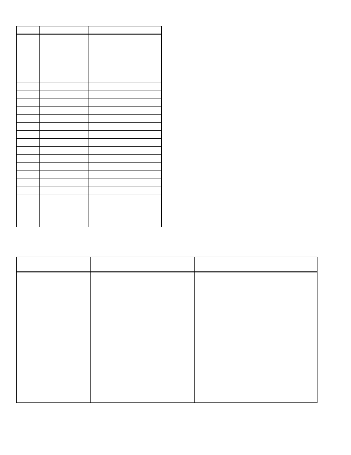
SPECIFICATION
Items Contents
Dimensions ( W × H × D ) 68.6 cm × 52.5 cm × 22.5 cm [Included stand]
68.6 cm × 47.4 cm × 12.2 cm [TV only]
Mass 15.6 kg [Included stand]
12.4 kg [TV only]
Power Input AC110V - AC240 V, 50 Hz / 60 Hz
Power Consumption 104 W (Standby: 2.0 W)
TV RF System CCIR (B/G, I, D/K, L)
Colour System PAL, SECAM, NTSC 3.58/4.43 [EXT only]
Stereo System NICAM (B/G, I, D/K, L), A2 (B/G, D/K)
Teletext System FLOF (Fastext level 2.5), TOP, WST(World Standard system)
Receiving Frequency VHF: 47MHz - 470MHz
UHF: 470MHz - 862MHz
Intermediate
Frequency
Colour Sub
Carrier Frequency
LCD panel 26V-inch wide aspect (16 : 9)
Screen Size Diagonal : 66 cm (H: 57.6 cm × V: 32.4 cm)
Display Pixels Horizontal : 1366 dots × Vertical : 768 dots (W-XGA)
Audio Power Output 10 W + 10 W
Speaker 6.6 cm, round type × 2 (Oblique corn)
Aerial terminal (VHF/UHF) 75 Ω unbalanced, coaxial
EXT-1 / EXT-2 (Input / Output) 21-pin Euro connector (SCART socket ) × 2
EXT-3 (Input) S-Video
EXT-4 (Input) Component Video
625p / 525p / 625i / 525i
PC (RGB) Input D-sub 15 pin × 1
Headphone 3.5 mm stereo mini jack × 1
Remote Control Unit RM-C1816S (AA/R6 dry cell battery × 2)
Design & specifications are subject to change without notice.
VIF 38.9MHz (B/G, I, D/K, L)
SIF 33.4MHz (5.5MHz :B/G)
32.9MHz (6.0MHz :I)
32.4MHz (6.5MHz :D/K)
PAL 4.43MHz
SECAM 4.40625MHz / 4.25MHz
NTSC 3.58MHz / 4.43MHz
Mini-DIN 4 pin × 1
Y: 1 V (p-p), Positive (Negative sync provided), 75 Ω
C: 0.286 V (p-p) (Burst signal), 75 Ω
Video
1 V (p-p), Positive (Negative sync provided), 75 Ω, RCA pin jack × 1
Audio
500 mV (rms), High impedance, RCA pin jack × 2
RCA pin jack × 3
Y : 1 V (p-p) (Sync signal: ±0.35V(p-p), 3-value sync.), 75Ω
750p
Pb/Pr : ±0.35V(p-p), 75 Ω
Y : 1 V (p-p), Positive (Negative sync provided), 75 Ω
Cb/Cr : 0.7V(p-p), 75 Ω
R/G/B : 0.7 V (p-p), 75Ω
HD / VD : 1 V (p-p) to 5 V (p-p), high impedance
< Available signal >
VGA : 640 pixels × 480 pixels (Horizontal : 31.5 kHz / Vertical : 60 Hz)
XGA : 1024 pixels × 768 pixels (Horizontal : 48.4 kHz / Vertical : 60 Hz)
1-2 (No.YA314)
Page 4

SECTION 1
PRECAUTION
1.1 SAFETY PRECAUTIONS [EXCEPT FOR UK]
(1) The design of this product contains special hardware,
many circuits and components specially for safety
purposes. For continued protection, no changes should be
made to the original design unless authorized in writing by
the manufacturer. Replacement parts must be identical to
those used in the original circuits. Service should be
performed by qualified personnel only.
(2) Alterations of the design or circuitry of the products should
not be made. Any design alterations or additions will void
the manufacturer's warranty and will further relieve the
manufacturer of responsibility for personal injury or
property damage resulting therefrom.
(3) Many electrical and mechanical parts in the products have
special safety-related characteristics. These
characteristics are often not evident from visual inspection
nor can the protection afforded by them necessarily be
obtained by using replacement components rated for
higher voltage, wattage, etc. Replacement parts which
have these special safety characteristics are identified in
the parts list of Service manual. Electrical components
having such features are identified by shading on the
schematics and by ( ) on the parts list in Service
manual. The use of a substitute replacement which does
not have the same safety characteristics as the
recommended replacement part shown in the parts list of
Service manual may cause shock, fire, or other hazards.
(4) Don't short between the LIVE side ground and
ISOLATED (NEUTRAL) side ground or EARTH side
ground when repairing.
Some model's power circuit is partly different in the GND.
The difference of the GND is shown by the LIVE : ( ) side
GND, the ISOLATED (NEUTRAL) : ( ) side GND and
EARTH : ( ) side GND.
Don't short between the LIVE side GND and ISOLATED
(NEUTRAL) side GND or EARTH side GND and never
measure the LIVE side GND and ISOLATED (NEUTRAL)
side GND or EARTH side GND at the same time with a
measuring apparatus (oscilloscope etc.). If above note will
not be kept, a fuse or any parts will be broken.
(5) When service is required, observe the original lead dress.
Extra precaution should be given to assure correct lead
dress in the high voltage circuit area. Where a short circuit
has occurred, those components that indicate evidence of
overheating should be replaced. Always use the
manufacturer's replacement components.
(6) Isolation Check (Safety for Electrical Shock Hazard)
After re-assembling the product, always perform an
isolation check on the exposed metal parts of the cabinet
(antenna terminals, video/audio input and output terminals,
Control knobs, metal cabinet, screw heads, earphone jack,
control shafts, etc.) to be sure the product is safe to operate
without danger of electrical shock.
a) Dielectric Strength Test
The isolation between the AC primary circuit and all metal
parts exposed to the user, particularly any exposed metal
part having a return path to the chassis should withstand a
voltage of 3000V AC (r.m.s.) for a period of one second. (.
. . . Withstand a voltage of 1100V AC (r.m.s.) to an
appliance rated up to 120V, and 3000V AC (r.m.s.) to an
appliance rated 200V or more, for a period of one second.)
This method of test requires a test equipment not generally
found in the service trade.
b) Leakage Current Check
Plug the AC line cord directly into the AC outlet (do not use
a line isolation transformer during this check.). Using a
"Leakage Current Tester", measure the leakage current
from each exposed metal part of the cabinet, particularly
any exposed metal part having a return path to the chassis,
to a known good earth ground (water pipe, etc.). Any
leakage current must not exceed 0.5mA AC (r.m.s.).
However, in tropical area, this must not exceed 0.2mA AC
(r.m.s.).
Alternate Check Method
Plug the AC line cord directly into the AC outlet (do not
use a line isolation transformer during this check.). Use
an AC voltmeter having 1000Ω per volt or more
sensitivity in the following manner. Connect a 1500Ω
10W resistor paralleled by a 0.15µF AC-type capacitor
between an exposed metal part and a known good earth
ground (water pipe, etc.). Measure the AC voltage
across the resistor with the AC voltmeter. Move the
resistor connection to each exposed metal part,
particularly any exposed metal part having a return path
to the chassis, and measure the AC voltage across the
resistor. Now, reverse the plug in the AC outlet and
repeat each measurement. Any voltage measured must
not exceed 0.75V AC (r.m.s.). This corresponds to
0.5mA AC (r.m.s.).
However, in tropical area, this must not exceed 0.3V AC
(r.m.s.). This corresponds to 0.2mA AC (r.m.s.).
AC VOLTMETER
(HAVING 1000 /V,
OR MORE SENSITIVITY)
0.15 F AC-TYPE
GOOD EARTH GROUND
1500 10W
PLACE THIS PROBE
ON EACH EXPOSED
ME TAL PAR T
(No.YA314)1-3
Page 5

1.2 SAFETY PRECAUTIONS [FOR UK]
(1) The design of this product contains special hardware and many circuits and components specially for safety purposes. For
continued protection, no changes should be made to the original design unless authorized in writing by the manufacturer.
Replacement parts must be identical to those used in the original circuits. Service should be performed by qualified personnel
only.
(2) Alterations of the design or circuitry of the product should not be made. Any design alterations or additions will void the
manufacturer's warranty and will further relieve the manufacturer of responsibility for personal injury or property damage
resulting therefrom.
(3) Many electrical and mechanical parts in the product have special safety-related characteristics. These characteristics are often
not evident from visual inspection nor can the protection afforded by them necessary be obtained by using replacement
components rated for higher voltage, wattage, etc. Replacement parts which have these special safety characteristics are
identified in the Parts List of Service Manual. Electrical components having such features are identified by shading on the
schematics and by ( ) on the Parts List in the Service Manual. The use of a substitute replacement which does not have the
same safety characteristics as the recommended replacement part shown in the Parts List of Service Manual may cause shock,
fire, or other hazards.
(4) The leads in the products are routed and dressed with ties, clamps, tubing’s, barriers and the like to be separated from live parts,
high temperature parts, moving parts and / or sharp edges for the prevention of electric shock and fire hazard. When service is
required, the original lead routing and dress should be observed, and it should be confirmed that they have been returned to
normal, after re-assembling.
WARNING
(1) The equipment has been designed and manufactured to meet international safety standards.
(2) It is the legal responsibility of the repairer to ensure that these safety standards are maintained.
(3) Repairs must be made in accordance with the relevant safety standards.
(4) It is essential that safety critical components are replaced by approved parts.
(5) If mains voltage selector is provided, check setting for local voltage.
1-4 (No.YA314)
Page 6
1.3 INSTALLATION
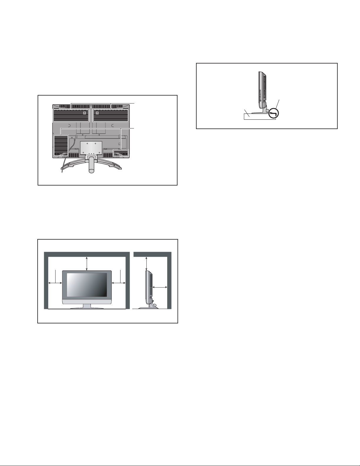
1.3.1 HEAT DISSIPATION
If the heat dissipation vent behind this unit is blocked, cooling
efficiency may deteriorate and temperature inside the unit will
rise. The temperature sensor that protects the unit will be
activated when internal temperature exceeds the pre-determined
level and power will be turned off automatically.Therefore,
please make sure pay attention not to block the heat dissipation
vent as well as the ventilation outlet behind the unit and ensure
that there is room for ventilation around it.
Ventilation hole
1.3.3 INSTALLATION REQUIREMENTS
To ensure safety in an emergency such as an earthquake, and
to prevent accidents, ensure that measures are taken to prevent
the TV dropping or falling over.
It fixes in a band.
TV Stand
Ventilation hole
*Diagram differs from actual appearance.
1.3.2 INSTALLATION REQUIREMENTS
Ensure that the minimal distance is maintained, as specified
below, between the unit with and the surrounding walls, as well
as the floor etc.Install the unit on stable flooring or stands.Take
precautionary measures to prevent the unit from tipping in order
to protect against accidents and earthquakes.
150 mm 150 mm
200 mm 200 mm
50 mm
*Diagram differs from actual appearance.
1.3.4 NOTES ON HANDLING
(1) WHEN TAKING UNIT OUT OF A PACKING CASE
When taking the unit out of a packing case, do not grasp
the upper part of the unit. If you take the unit out while
grasping the upper part, the LCD PANEL may be damaged
because of a pressure. Instead of grasping the upper part,
put your hands on the lower backside or sides of the unit.
(2) AS FOR PRESSING OR TOUCHING A SPEAKER
Be careful not to press the opening of the speaker in the
lower part of the unit and around them since the decorative
sheet on the surface of the openings may be deformed.
*Diagram differs from actual appearance.
(No.YA314)1-5
Page 7

1.4 HANDLING LCD PANEL
1.4.1 PRECAUTIONS FOR TRANSPORTATION
When transporting the unit, pressure exerted on the internal LCD
panel due to improper handling (such as tossing and dropping)
may cause damages even when the unit is carefully packed. To
prevent accidents from occurring during transportation, pay
careful attention before delivery, such as through explaining the
handling instructions to transporters.
Ensure that the following requirements are met during
transportation, as the LCD panel of this unit is made of glass and
therefore fragile:
(1) USE A SPECIAL PACKING CASE FOR THE LCD PANEL
When transporting the LCD panel of the unit, use a special
packing case (packing materials). A special packing case
is used when a LCD panel is supplied as a service spare
part.
(2) ATTACH PROTECTION SHEET TO THE FRONT
Since the front (display part) of the panel is vulnerable,
attach the protection sheet to the front of the LCD panel
before transportation. Protection sheet is used when a LCD
panel is supplied as a service spare part.
(3) AVOID VIBRATIONS AND IMPACTS
The unit may be broken if it is toppled sideways even when
properly packed. Continuous vibration may shift the gap of
the panel, and the unit may not be able to display images
properly. Ensure that the unit is carried by at least 2
persons and pay careful attention not to exert any vibration
or impact on it.
(4) DO NOT PLACE EQUIPMENT HORIZONTALLY
Ensure that it is placed upright and not horizontally during
transportation and storage as the LCD panel is very
vulnerable to lateral impacts and may break. During
transportation, ensure that the unit is loaded along the
traveling direction of the vehicle, and avoid stacking them
on one another. For storage, ensure that they are stacked
in 2 layers or less even when placed upright.
1.4.2 OPTICAL FILTER (ON THE FRONT OF THE LCD PANEL)
(1) Avoid placing the unit under direct sunlight over a
prolonged period of time. This may cause the optical filter
to deteriorate in quality and COLOUR.
(2) Clean the filter surface by wiping it softly and lightly with a
soft and lightly fuzz cloth (such as outing flannel).
(3) Do not use solvents such as benzene or thinner to wipe the
filter surface. This may cause the filter to deteriorate in
quality or the coating on the surface to come off. When
cleaning the filter, usually use the neutral detergent diluted
with water. When cleaning the dirty filter, use water-diluted
ethanol.
(4) Since the filter surface is fragile, do not scratch or hit it with
hard materials. Be careful enough not to touch the front
surface, especially when taking the unit out of the packing
case or during transportation.
1.4.3 PRECAUTIONS FOR REPLACEMENT OF EXTERIOR
PARTS
Take note of the following when replacing exterior parts (REAR
COVER, FRONT PANEL, etc.):
(1) Do not exert pressure on the front of the LCD panel (filter
surface). It may cause irregular COLOUR.
(2) Pay careful attention not to scratch or stain the front of the
LCD panel (filter surface) with hands.
(3) When replacing exterior parts, the front (LCD panel) should
be placed facing downward. Place a mat, etc. underneath
to avoid causing scratches to the front (filter surface).
1-6 (No.YA314)
Page 8
SECTION 2
SPECIFIC SERVICE INSTRUCTIONS
2.1 FEATURES
T-V LINK
When you have a T-V LINK compatible VCR connected to the
EXT-2 Terminal on the TV,it is easier to set up the VCR and to
view videos.
PICTURE MODE
This function can adjust the picture settings automatically.
ZOOM
This function can change the screen size according to the
picture aspect ratio.
2.2 MAIN DIFFERENCE LIST
Item LT-26A60BU LT-26A60SU LT-26A60SJ
FRONT PANEL COLOUR BLACK SILVER SILVER
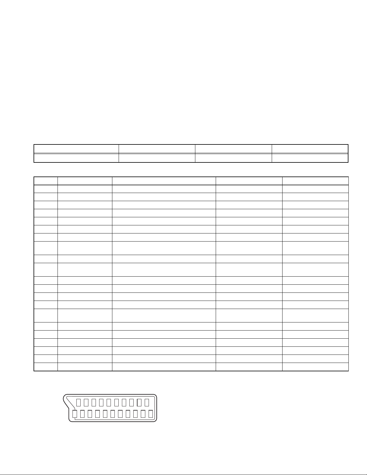
2.3 21-PIN EURO CONNECTOR (SCART) : EXT-1 / EXT-2
Pin No. Signal designation Matching value EXT-1 EXT-2
1 AUDIO R output 500mV(rms) (Nominal), Low impedance Used (TV OUT) Used (LINE OUT)
2 AUDIO R input 500mV(rms) (Nominal), High impedance Used (R1) Used (R2)
3 AUDIO L output 500mV(rms) (Nominal), Low impedance Used (TV OUT) Used (LINE OUT)
4 AUDIO GND Used Used
5 GND (B) Used Used
6 AUDIO L input 500mV(rms) (Nominal), High impedance Used (L1) Used (L2)
7 B input 700mV
8 FUNCTION SW
(SLOW SW)
Low : 0V-3V
High : 8V-12V, High impedance
, 75Ω Used Used
(B-W)
9 GND (G) Used Used
10 SCL / T-V LINK Not used Used
11 G input 700mV
, 75Ω Used Used
(B-W)
12 SDA Not used Used (SDA2)
13 GND (R) Used Used
14 GND (YS) Used Not used
15 R / C input R : 700mV
C : 300mV
(B-W)
(P-P)
, 75Ω
, 75Ω
16 Ys input (FAST SW) Low : 0V-0.4V, High : 1V-3V, 75Ω Used Used
17 GND (VIDEO output) Used Used
18 GND (VIDEO input) Used Used
19 VIDEO output 1V
20 VIDEO / Y input 1V
(Negative sync), 75Ω Used (TV OUT) Used (LINE OUT)
(P-P)
(Negative sync), 75Ω Used Used
(P-P)
21 COMMON GND Used Used
3D SOUND
This function can enjoy Surround sound with a "live" effect by
using the 3D SOUND.
DIGITAL VNR
This function cuts down the amount of noise in the original
picture.
COLOUR SYSTEM
If the picture is not clear or no colour appears, change the
current colour system to another colour system.
Used Used
(SCL2 / TV-LINK)
Used (R) Used (C2/R)
(P-P= Peak to Peak, B-W= Blanking to white peak)
[Pin assignment]
20 18 16 14 12 10 8 6 4 2
21 19 17 15 13 11 9 7 5 3 1
(No.YA314)1-7
Page 9

2.4 TECHNICAL INFORMATION
2.4.1 LCD PANEL
This unit uses the flat type panel LCD (Liquid Crystal Display) panel that occupies as little space as possible, instead of the
conventional CRT (Cathode Ray Tube), as a display unit.
Since the unit has the two polarizing filter that are at right angles to each other, the unit adopts "normally black" mode, where light
does not pass through the polarizing filter and the screen is black when no voltage is applied to the liquid crystals.
2.4.1.1 SPECIFICATIONS
The following table shows the specifications of this unit.
Item Specifications
Maximum dimensions ( W × H × D ) 626.0 mm × 373.0 mm × 51.0 mm
Weight 4.7 kg
Effective screen size Diagonal: 660 mm (H: 576 mm × V: 324 mm)
Aspect ratio 16 : 9
Drive device / system a-Si-TFT active matrix system
Resolution Horizontally 1366 × Vertically 768 × RGB < W-XGA > 3147264 dots in total
Pixel pitch (pixel size) Horizontally: 0.4215 mm Vertically: 0.4215mm
Displayed colour 16777216 colours 256 colours for R G and B
Brightness 500cd/m2
Contrast ratio 800 : 1
Response time 8ms
View angle Horizontally: 170° Vertically: 170°
Surface polarizer Anti-Glare type Low reflective coat
Colour filter Vertical stripe
Backlight U-type Cold cathode fluorescent lamp × 8
Power supply voltage in LCD 6.5 V
Power supply voltage in inverter 26.4 V
Panel interface system LVDS (Low Voltage Differential Signaling)
2.4.1.2 PIXEL FAULT
There are three pixel faults - bright fault , dark fault and flicker fault - that are respectively defined as follows.
BRIGHT FAULT
In this pixel fault, a cell that should not light originally is lighting on and off.
For checking this pixel fault, input ALL BLACK SCREEN and find out the cell that is lighting on and off.
DARK FAULT
In this pixel fault, a cell that should light originally is not lighting or lighting with the brightness twice as brighter as originally lighting.
For checking this pixel fault, input 100% of each R/G/B colour and find out the cell that is not lighting.
FLICKER FAULT
In the pixel fault, a cell that should light originally or not light originally is flashing on and off.
For checking this pixel fault, input ALL BLACK SCREEN signal or 100% of each RGB colour and find out the cell that is flashing on
and off.
1-8 (No.YA314)
Page 10

2.4.2 MAIN CPU PIN FUNCTION [U302 : MAIN PWB]
Pin Pin name I/O Function Pin Pin name I/O Function
1 D1 I/O Program ROM data for CPU 51 NC2 - Not used
2 D4 I/O Program ROM data for CPU 52 XTAL2 O 6MHz for system clock
3 D2 I/O Program ROM data for CPU 53 XTAL1 I 6MHz for system clock
4 D3 I/O Program ROM data for CPU 54 NC3 - Not used
5XROM O
6 VDD 2.5 I 2.5V 56 VDDA 2.5 I 2.5V
7 VSS - GND 57 R O R for teletext
8 VDD 3.5 I 3.5V 58 G O G for teletext
9 P0.0 I/O Address/Data for scaler IC 59 B O B for teletext
10 P0.1 I/O Address/Data for scaler IC 60
11 P0.2 I/O Address/Data for scaler IC 61 NC4 - Not used
12 P0.3 I/O Address/Data for scaler IC 62 P1.7 O Reset for Scaler IC [H=Reset]
13 P0.4 - Not used 63 NC5 - Not used
14 P0.5 O Address latch Enable 64 WR O Write for memory
15 P0.6 - Not used 65 RD O Read for memory
16 P0.7 - Not used 66 NC6 Not used
17 ENE - Not used 67 A19 O Program ROM address for CPU
18 STOP - Not used 68 A18 O Program ROM address for CPU
19 OCF - Not used 69 A16 O Program ROM address for CPU
20 EXTIF - Not used 70 A17 O Program ROM address for CPU
21 CVBS I Video for teletext 71 A15 O Program ROM address for CPU
22 VDDA 2.5 I 2.5V 72 FL_PGM - Test purpose
23 VSSA - GND 73 VDD 2.5 I 2.5V
24 P2.0 I Scart2 ID [H=Detect] 74 VSS - GND
25 P2.1 I key scan data 1 75 VDD 3.3 I 3.3V
26 P2.2 I key scan data 2 76 A14 O Program ROM address for CPU
27 P2.3 I Scaet1 ID [H=Detect] 77 A12 O Program ROM address for CPU
28 NC1 - Not used 78 A13 O Program ROM address for CPU
29 HS/SSC I Horizontal sync 79 A7 O Program ROM address for CPU
30 VS I Vertical sync 80 FL_RST - Test purpose
31 P3.0 O Data Read for Scaler IC 81 A8 O Program ROM address for CPU
32 P3.1 O Comunication for adjustment [H=TXD] 82 A6 O Program ROM address for CPU
33 P3.2 I TV-Link in 83 A9 O Program ROM address for CPU
34 P3.3 I Remote control 84 A5 O Program ROM address for CPU
35 P3.4 I/O I2C bus Data(for EEPROM) 85 A11 O Program ROM address for CPU
36 P3.5 O I2C bus Clock(for EEPROM) 86 A4 O Program ROM address for CPU
37 P3.6 O Data Write for Scaler IC 87 ALE O Address Latch Enable
38 P3.7 I Comunication for adjustment [H=RXD] 88 PSEN O Program Store Enable
39 VSS - GND 89 A3 O Program ROM address for CPU
40 VDD 3.3 I 3.3V 90 A10 O Program ROM address for CPU
41 P1.0 O RGB Select [L=SCART1, H=SCART2] 91 VSS - GND
42 P1.1 I Headphone Ident [L=Detect] 92 VDD 3.3 I 3.3V
43 P1.2 I/O I2C bus Data(for inter IC) 93 A2 O Program ROM address for CPU
44 P1.3 O I2C bus Clock(for inter IC) 94 A1 O Program ROM address for CPU
45 P1.4 O Reset for inter IC [L=Reset] 95 FL_CE - Test purpose
46 P1.5 I PC Detect [L=Detect] 96 D7 I/O Program ROM data for CPU
47 P1.6 O Memory Pack I2C S/W [L=Detect] 97 A0 O Program ROM address for CPU
48 P4.2 O Main power control [L=ON, H=OFF] 98 D6 I/O Program ROM data for CPU
49 P4.3 O TV-Link out 99 D0 I/O Program ROM data for CPU
50 RST O Reset [L=Reset] 100 D5 I/O Program ROM data for CPU
This pin must be pulled low to access external ROM.
55 VSSA - GND
BLANK/COR
O Ys for Teletext
(No.YA314)1-9
Page 11

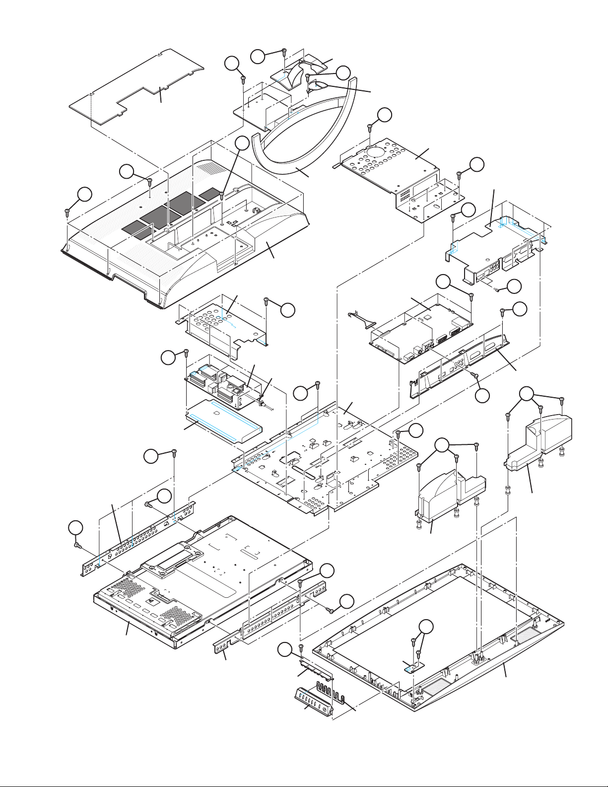
SECTION 3
DISASSEMBLY
3.1 DISASSEMBLY PROCEDURE
CAUTION AT DISASSEMBLY:
• Make sure that the power cord is disconnected from the outlet.
• Pay special attention not to break or damage the parts.
• When removing each board, remove the connectors as required. Taking notes of the connecting points (connector numbers)
makes service procedure manageable.
• Make sure that there is no bent or stain on the connectors before inserting, and firmly insert the connectors.
3.1.1 REMOVING THE STAND
(1) Remove the JACK COVER.
(2) Remove the 2 screws [A], then remove the STAND
COVER.
(3) Remove the 2 screws [W], then remove the CABLE
COVER.
(4) Remove the 4 screws [B], then remove the STAND.
3.1.2 REMOVING THE REAR COVER
• Remove the STAND.
(1) Remove the 8 screws [C], 1 screw [D] and 2 screws [E],
then remove the REAR COVER.
3.1.3 REMOVING THE POWER PWB
• Remove the STAND.
• Remove the REAR COVER.
(1) Remove the 4 screws [G] and 1 screw [H], then remove the
TERMINAL BASE.
(2) Remove the 8 screws [F], then remove the BACK
BRACKET.
(3) Remove the 6 screws [J], then remove the POWER PWB
SHIELD.
(4) Remove the 5 screws [K], then remove the POWER PWB.
3.1.4 REMOVING THE MAIN PWB
• Remove the STAND.
• Remove the REAR COVER.
• Remove the TERMINAL BASE.
• Remove the BACK BRACKET.
• Remove the POWER PWB SHIELD.
(1) Remove the 7 screws [L] and 2 screws [N], then remove
the MAIN PWB SHIELD.
(2) Remove the 6 screws [M], then remove the MAIN PWB.
3.1.6 REMOVING THE LED PWB
• Remove the STAND.
• Remove the REAR COVER.
(1) Remove the 2 screws [Q], then remove the LED PWB.
3.1.7 REMOVING THE SPEAKER
• Remove the STAND.
• Remove the REAR COVER.
(1) Remove the 6 screws [R], then remove the SPEAKER (L/
R).
CAUTION:
Please do not disassembly the SPEAKER.
When the speaker is decomposed, the performance cannot be
kept.
3.1.8 REMOVING THE LCD PANEL UNIT
• Remove the STAND.
• Remove the REAR COVER.
• Remove the TERMINAL BASE.
• Remove the BACK BRACKET.
(1) Remove the 6 screws [S], then remove the MAIN BASE.
(2) Remove the 6 screws [T], then remove the FRONT
PANEL.
(3) Remove the 2 screws [U], then remove the TOP FRAME.
(4) Remove the 2 screws [V], then remove the BOTTOM
FRAME.
3.1.5 REMOVING THE CONTROL PWB
• Remove the STAND.
• Remove the REAR COVER.
(1) Remove the 2 screws [P], then remove the CONTROL
PWB.
1-10 (No.YA314)
Page 12
JACK COVER
A
B
STAND COVER
W
CABLE COVER
F
E
D
STAND
BACK BRACKET
F
MAIN PWB SHIELD
C
L
REAR COVER
K
INSULATOR
POWER PWB SHIELD
J
POWER PWB
POWER CORD
M
MAIN PWB
S
MAIN BASE
H
S
N
G
TERMINAL BASE
R
R
T
TOP FRAME
U
LCD PANEL UNIT
U
BOTTOM FRAME
P
CONTROL PWB
KNOB BASE
SPEAKER
SPEAKER
T
V
Q
LED PWB
FRONT PANEL
CONTROL KNOB
Fig.1
(No.YA314)1-11
Page 13
3.2 MEMORY IC REPLACEMENT
SERVICE MENU
1.ADJUST
2.SELF_CHECK
3.I2C STOP
S001 5I R OF 126
PAL50 FULL STD H
• This model uses the memory IC.
• This memory IC stores data for proper operation of the video and drive circuits.
• When replacing, be sure to use an IC containing this (initial value) data.
3.2.1 MEMORY IC REPLACEMENT PROCEDURE
1. Power off
Switch off the power and disconnect the power plug from the AC outlet.
2. Replace the memory IC
Be sure to use the memory IC written with the initial setting values.
3. Power on
Connect the power plug to the AC outlet and switch on the power.
4. Receiving channel setting
Refer to the OPERATING INSTRUCTIONS and set the receive channels (Channels Preset) as described.
5. User setting
Check the user setting items according to the given in page later. Where these do not agree, refer to the OPERATING
INSTRUCTIONS and set the items as described.
6. SERVICE MODE setting
Verify what to set in the SERVICE MODE, and set whatever is necessary (Fig.1). Refer to the SERVICE ADJUSTMENT for setting.
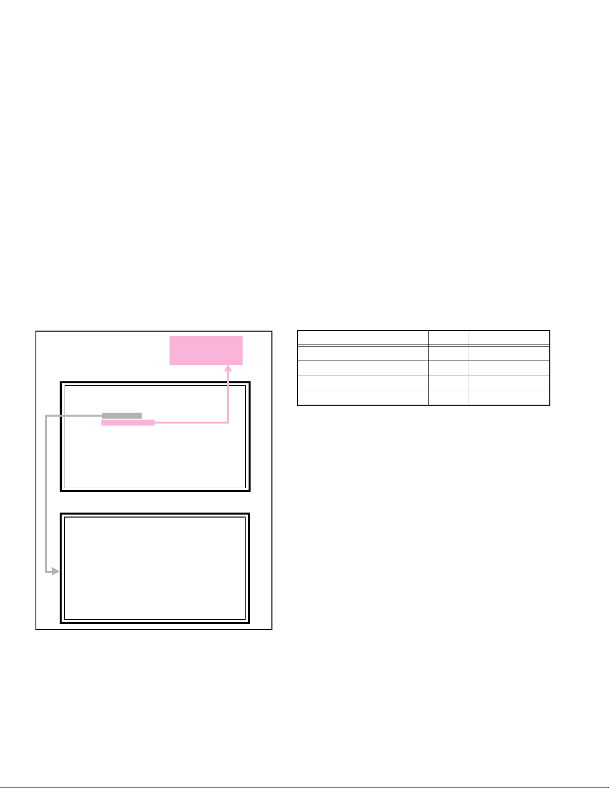
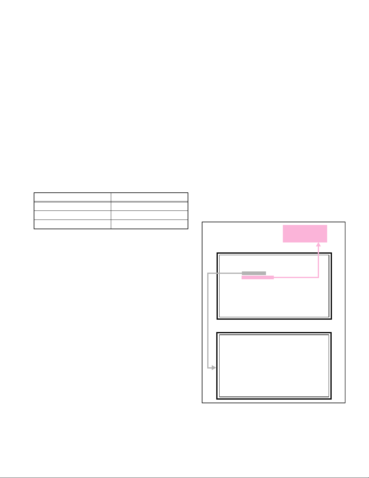
3.2.2 SERVICE MODE SETTING
SERVICE MODE SCREEN
Not used
(Display only)
SERVICE MODE SCREEN
SETTING ITEM
Setting items Settings Item No.
Video system setting -1 Adjust S001 - S043
Video system setting -2 Fixed M001 - M009
Audio System Setting Fixed A001 - A003
Video system setting -3 Fixed D001 - D051
SERVICE MENU
1.ADJUST
2.SELF_CHECK
3.I2C STOP
ADJUSTMENT MODE SCREEN
S001 5I R OF 126
PAL50 FULL STD H
Fig.1
NOTE:
As self check feature is not used in this TV,
“2.SELF_CHECK” cannot be selected (screen display
only).
1-12 (No.YA314)
Page 14
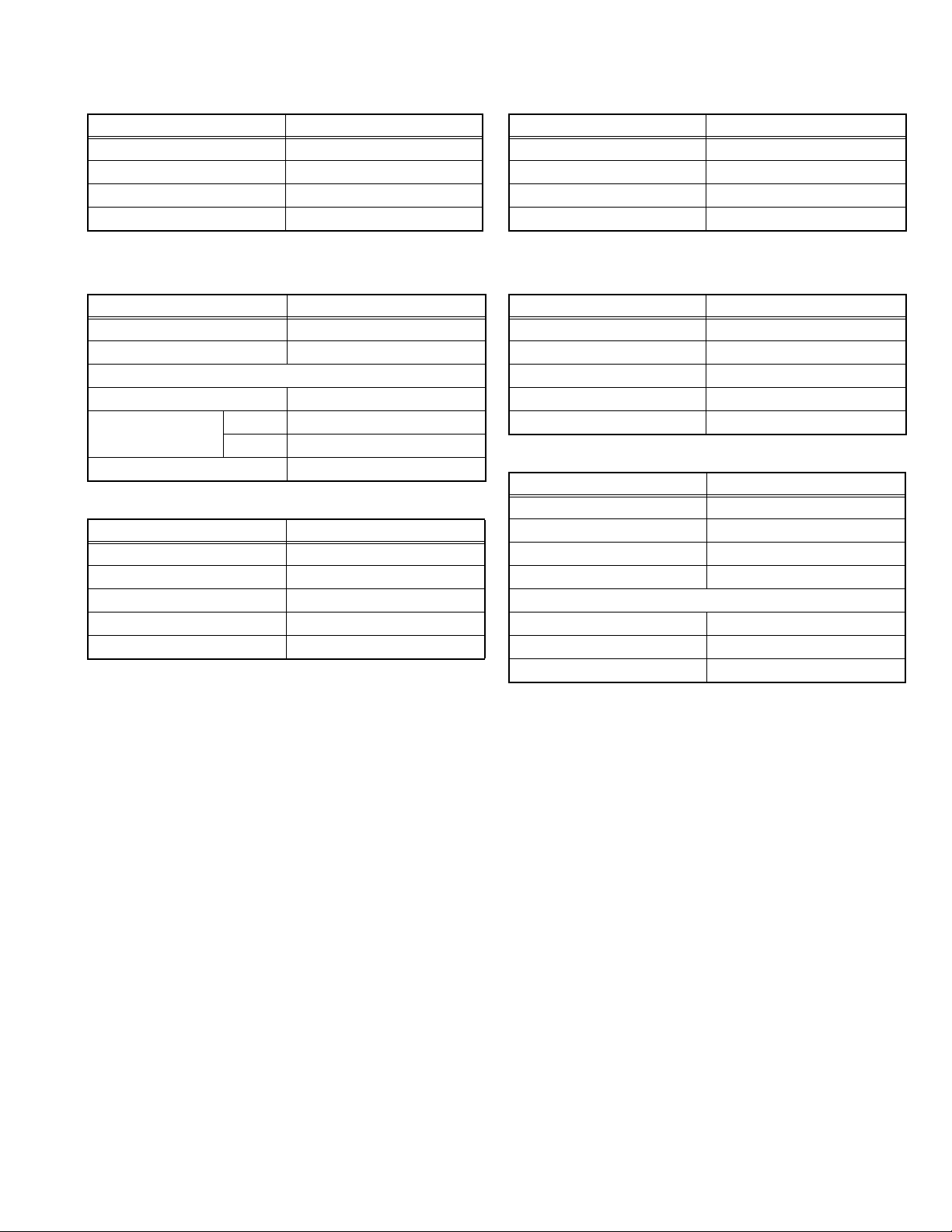
3.2.3 SETTINGS OF FACTORY SHIPMENT
3.2.3.1 BUTTON OPERATION 3.2.3.2 REMOTE CONTROL DIRECT OPERATION
Setting item Setting position
POWER Off
CHANNEL PR1
VOLUME 10
TV/AV TV
3.2.3.3 REMOTE CONTROL MENU OPERATION
(1) PICTURE
Setting item Setting position
PICTURE MODE BRIGHT
COLOUR TEMP. COOL
FEATURES
DIGITAL VNR AUTO (LOW)
COLOUR SYSTEM TV Depends on PR/CH
EXT AUTO
4:3 AUTO ASPECT PANORAMIC
(2) SOUND
Setting item Setting position
STEREO / I•II Stereo sound
BASS Centre
TREBLE Centre
BALANCE Centre
3D SOUND OFF
CHANNEL PR1
VOLUME 10
ZOOM PANORAMIC
3D SOUND OFF
(4) FEATURES
SLEEP TIMER OFF
CHILD LOCK ID NO.0000, All CH off
APPEARANCE TYPE D
BLUE BACK ON
FAVOURITE SETTING Reset
(5) SET UP
AUTO PROGRAM TV channel automatically set
EDIT/MANUAL PRESET CH only
LANGUAGE ENGLISH
DECODER (EXT-2) OFF
EXT SETTING
S-IN BLANK
ID BLANK
DUBBING EXT-1 → EXT-2
Setting item Setting position
Setting item Setting position
Setting item Setting position
(No.YA314)1-13
Page 15
3.3 REPLACEMENT OF CHIP COMPONENT
3.3.1 CAUTIONS
(1) Avoid heating for more than 3 seconds.
(2) Do not rub the electrodes and the resist parts of the pattern.
(3) When removing a chip part, melt the solder adequately.
(4) Do not reuse a chip part after removing it.
3.3.2 SOLDERING IRON
(1) Use a high insulation soldering iron with a thin pointed end of it.
(2) A 30w soldering iron is recommended for easily removing parts.
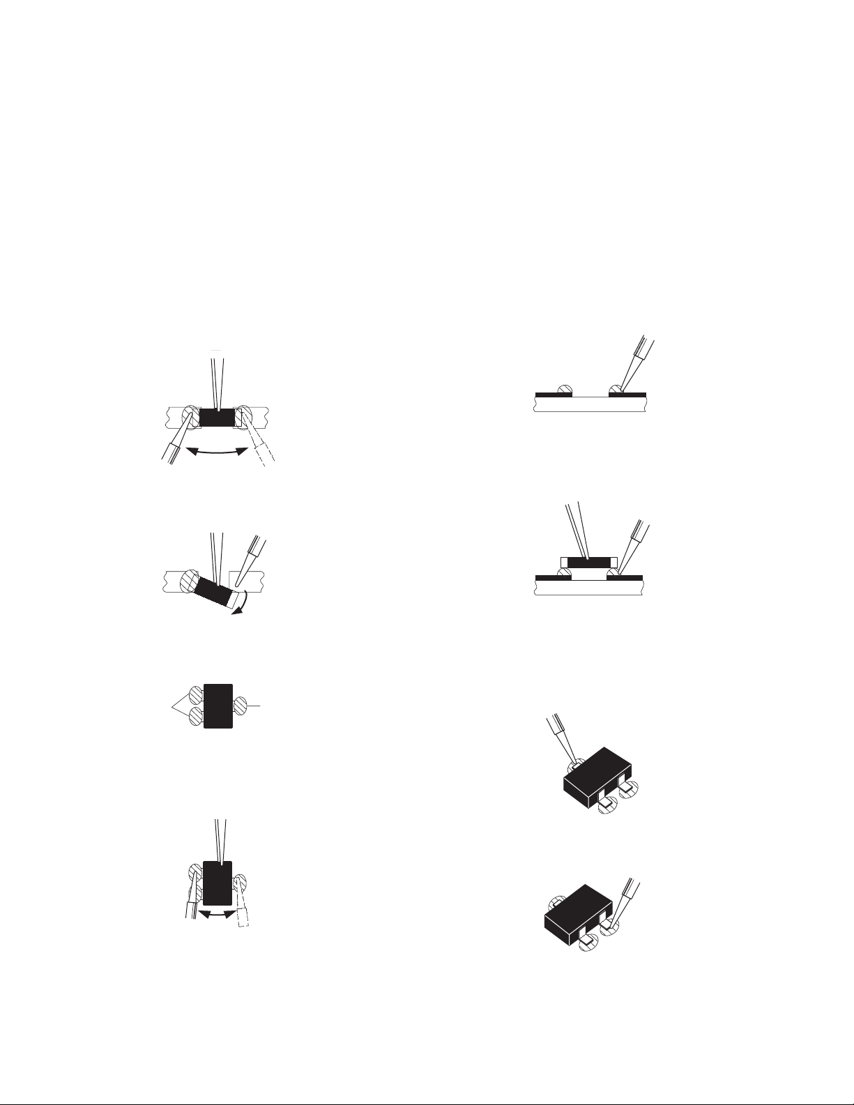
3.3.3 REPLACEMENT STEPS
1. How to remove Chip parts
2. How to install Chip parts
[Resistors, capacitors, etc.]
(1) As shown in the figure, push the part with tweezers and
alternately melt the solder at each end.
(2) Shift with the tweezers and remove the chip part.
[Transistors, diodes, variable resistors, etc.]
(1) Apply extra solder to each lead.
SOLDER
SOLDER
[Resistors, capacitors, etc.]
(1) Apply solder to the pattern as indicated in the figure.
(2) Grasp the chip part with tweezers and place it on the
solder. Then heat and melt the solder at both ends of the
chip part.
[Transistors, diodes, variable resistors, etc.]
(1) Apply solder to the pattern as indicated in the figure.
(2) Grasp the chip part with tweezers and place it on the
solder.
(3) First solder lead A as indicated in the figure.
(2) As shown in the figure, push the part with tweezers and
alternately melt the solder at each lead. Shift and remove
the chip part.
NOTE :
After removing the part, remove remaining solder from the
pattern.
1-14 (No.YA314)
A
B
C
(4) Then solder leads B and C.
A
B
C
Page 16
SECTION 4
SERVICE MENU
1.ADJUST
2.SELF_CHECK
3.I2C STOP
S001 5I R OF 126
PAL50 FULL STD H
ADJUSTMENT
4.1 ADJUSTMENT PREPARATION
(1) The adjustment using the REMOTE CONTROL UNIT is
made on the basis of the initial setting values. The
setting values which adjust the screen to the optimum
condition can be different from the initial setting
values.
(2) Make sure that connection is correctly made AC to AC
power source.
(3) Turn on the power of the TV and measuring instruments for
warming up for at least 30 minutes before starting
adjustments.
(4) If the receive or input signal is not specified, use the most
appropriate signal for adjustment.
(5) Never touch the parts (such as variable resistors,
transformers and condensers) not shown in the adjustment
items of this service adjustment.
4.2 PRESET SETTING BEFORE ADJUSTMENTS
Unless otherwise specified in the adjustment items, preset the
following functions with the REMOTE CONTROL UNIT.
Setting item Settings position
PICTURE MODE STANDARD
PICTURE adjustments Centre
COLOUR TEMP. NORMAL
4.3 MEASURING INSTRUMENT AND FIXTURES
• Signal generator (Pattern generator)[PAL]
• Remote control unit
4.4 ADJUSTMENT ITEMS
VIDEO CIRCUIT
• WHITE BALANCE (HIGH LIGHT) adjustment
4.5 BASIC OPERATION OF SERVICE MODE
4.5.1 HOW TO ENTER THE SERVICE MODE
(1) Press [INFORMATION] key and [MUTING] key on the
remote control unit simultaneously to enter the SERVICE
MODE SCREEN.
(2) In the SERVICE MENU, press the [1] key to display
ADJUSTMENT MODE SCREEN.
NOTE:
• As self check feature is not used in this TV,
“2.SELF_CHECK” cannot be selected (screen display
only).
• Before entering the SERVICE MODE, confirm that the
setting of VCR/TV/DVD switch is at the "TV" side. If the
switches have not been properly set, you cannot enter the
SERVICE MODE.
• When a number key other than the [1] key is pressed in the
SERVICE MODE SCREEN, the other relevant screen may
be displayed.
This is not used in the adjustment procedure. Press the
[MENU] key to return to the SERVICE MODE SCREEN.
Not used
(Display only)
SERVICE MODE SCREEN
SERVICE MENU
1.ADJUST
2.SELF_CHECK
3.I2C STOP
ADJUSTMENT MODE SCREEN
S001 5I R OF 126
PAL50 FULL STD H
4.5.2 HOW TO EXIT THE SERVICE MODE
Press the [MENU] key to exit the Service mode.
(No.YA314)1-15
Page 17
4.5.3 DESCRIPTION OF STATUS DISPLAY
S001 5I R OF 126
PAL50 FULL STD H
SETTING VALUE (DATA)SETTINGITEM No. SETTING ITEM
S001 5I R OF 126
PAL50 FULL STD H
SIGNAL SYSTEM
ZOOM MODE
PICTURE MODE
COLOUR TEMP.
(5) SETTING ITEM NAME
Setting item name are displayed. The setting item numbers to
be displayed are listed below.
Item No. Setting item
S001 - S043 Video system setting -1
M001 - M009 Video system setting -2
A001 - A003 Audio System Setting
D001 - D051 Video system setting -3
(6) SETTING ITEM NO.
Setting item numbers are displayed. For the setting item
names to be displayed, refer to "INITIAL SETTING VALUES
IN THE SERVICE MODE".
(1) SIGNAL SYSTEM
The signal displayed on the screen is displayed.
PAL50 : PAL50Hz (Composite / S-video)
PAL60 : PAL60Hz (Composite / S-video)
SECAM : SECAM
NTSC3 : NTSC3.58
NTSC4 : NTSC4.43
525I : 525i (Component)
525P : 525p
625I : 625i (Component)
625P : 625p
750P6 : 750p 60Hz
RGB5 : RGB 525i
RGB6 : RGB 625i
PCVGA : PC (VGA)
PCXGA : PC (XGA)
(2) ZOOM MODE
State of the screen mode is displayed.
NOTE:
In ADJUSTMENT MODE, the screen mode can be set only
to "FULL". When it is entered to ADJUSTMENT MODE, it is
automatically changed to "FULL", even if the setting is in
other screen mode.
(7) SETTING VALUE (DATA)
The SETTING VALUE is displayed.
4.5.4 CHANGE AND MEMORY OF SETTING VALUE
SELECTION OF SETTING ITEM
• [FUNCTION /] key.
For scrolling up / down the setting items.
S001... ↔ M001... ↔ A001... ↔ D001...
CHANGE OF SETTING VALUE (DATA)
• [FUNCTION /] key.
For scrolling up / down the setting values.
MEMORY OF SETTING VALUE (DATA)
Changed setting value is memorized by pressing [MUTING]
key.
4.5.5 SERVICE MODE SELECT KEY LOCATION
MUTING
NUMBER
VCR/TV/DVD
switch
(3) PICTURE MODE
State of the picture mode is displayed.
NOTE:
In ADJUSTMENT MODE, the picture mode can be set only
to "STANDARD". When it is entered to ADJUSTMENT
MODE, it is automatically changed to "STANDARD", even
if the setting is in other picture mode.
(4) COLOUR TEMP.
State of the colour temperature is displayed.
NOTE:
In ADJUSTMENT MODE, the colour temperature can be set
only to "NORMAL". When it is entered to ADJUSTMENT
MODE, it is automatically changed to "NORMAL", even if
the setting is in other colour temperature.
1-16 (No.YA314)
INFORMATION
FUNCTION /
MENU
FUNCTION /
Page 18
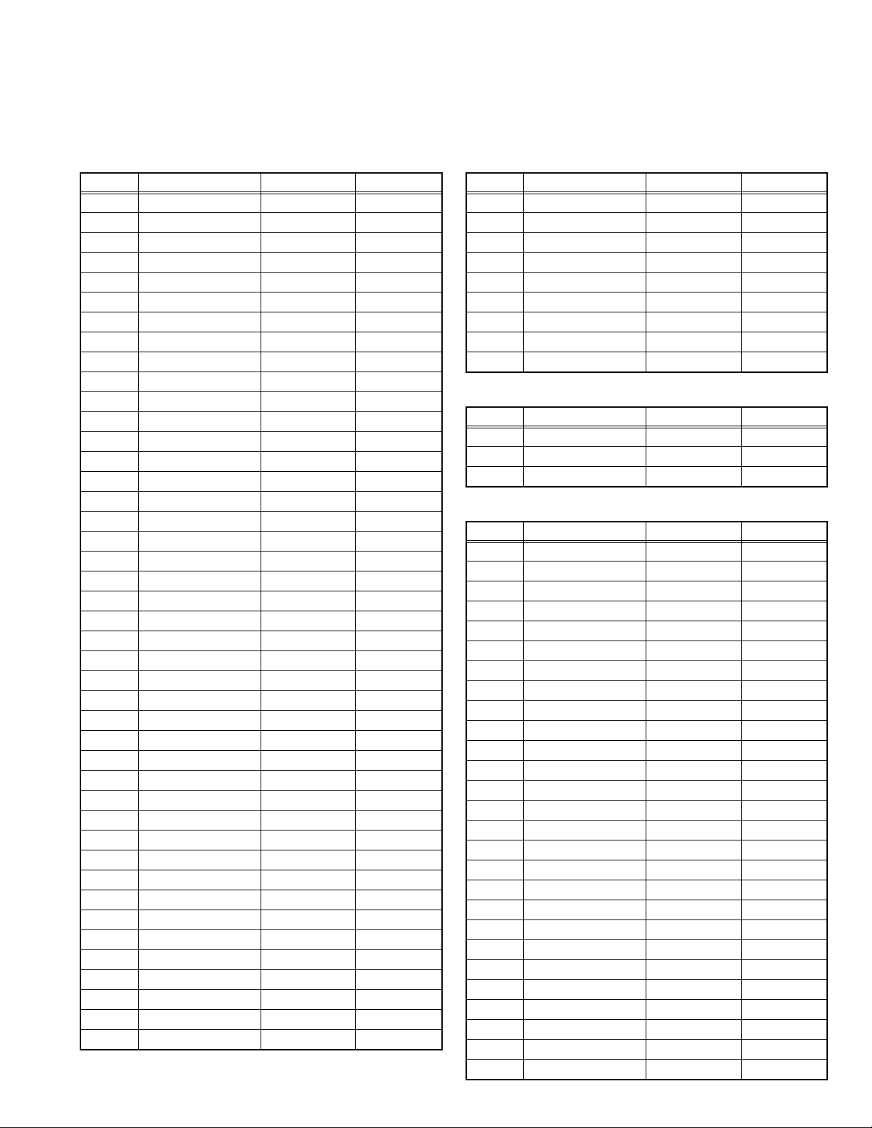
4.6 INITIAL SETTING VALUES IN THE SERVICE MODE
• Perform fine-tuning based on the "initial values" using the remote control when in the Service mode.
• The "initial values" serve only as an indication rough standard and therefore the values with which optimal display can be achieved
may be different from the default values. But, don't change the values that are not written in "ADJUSTMENT PROCEDURE". They
are fixed values.
4.6.1 VIDEO SYSTEM SETTING -1 4.6.2 VIDEO SYSTEM SETTING -2 (*Fixed values)
Item No. Item name Variable range Setting value
S001 5I R OF 000 - 255 122
S002 5I G OF 000 - 255 120
S003 5I B OF 000 - 255 122
S004 5P R OF 000 - 255 122
S005 5P G OF 000 - 255 120
S006 5P B OF 000 - 255 122
S007 HD75 R OF 000 - 255 127
S008 HD75 R OF 000 - 255 127
S009 HD75 R OF 000 - 255 127
S010 HD25 R OF 000 - 255 127
S011 HD25 R OF 000 - 255 127
S012 HD25 R OF 000 - 255 127
S013 R DRIVE 000 - 255 150
S014 G DRIVE 000 - 255 150
S015 B DRIVE 000 - 255 150
S016 HD R DR -32 - 31 -02
S017 HD G DR -32 - 31 07
S018 HD B DR -32 - 31 00
S019 CL R DR -32 - 31 00
S020 CL G DR -32 - 31 00
S021 CL B DR -32 - 31 11
S022 WM R DR -32 - 31 11
S023 WM G DR -32 - 31 00
S024 WM B DR -32 - 31 00
S025 HD CL R DR -32 - 31 00
S026 HD CL G DR -32 - 31 00
S027 HD CL B DR -32 - 31 00
S028 HD WM R DR -32 - 31 00
S029 HD WM G DR -32 - 31 00
S030 HD WM B DR -32 - 31 00
S031 PC R OF 000 - 255 133
S032 PC G OF 000 - 255 121
S033 PC B OF 000 - 255 115
S034 PC R DR -32 - 31 -15
S035 PC G DR -32 - 31 14
S036 PC B DR -32 - 31 10
S037 PC CL R DR -32 - 31 00
S038 PC CL G DR -32 - 31 00
S039 PC CL B DR -32 - 31 00
S040 PC WM R DR -32 - 31 00
S041 PC WM G DR -32 - 31 00
S042 PC WM B DR -32 - 31 00
S043 PC AUTO WB 000 - 001 000
Item No. Item name Variable range Setting value
M001 MV CON 000 - 255 104
M002 MV SHA 000 - 255 128
M003 MV COL 000 - 255 154
M004 MV TIN 000 - 255 048
M005 (Not display) 000 - 255 120
M006 CH MUTE 000 - 001 000
M007 PC R GAIN 000 - 001 097
M008 PC G GAIN 000 - 001 101
M009 PC B GAIN 000 - 001 101
4.6.3 AUDIO SYSTEM SETTING (*Fixed values)
Item No. Item name Variable range Setting value
A001 S BASS 000 - 016 008
A002 S TREBLE 000 - 016 008
A003 3D LEVEL 000 - 063 031
4.6.4 VIDEO SYSTEM SETTING -3 (*Fixed values)
Item No. Item name Variable range Setting value
D001 S CON 000 - 063 029
D002 S BRI 000 - 063 038
D003 S SHA 000 - 008 004
D004 S COL 000 - 063 032
D005 S TIN 000 - 063 032
D006 RGB S COL 000 - 127 032
D007 5I S CON 000 - 063 032
D008 5I S BRI 000 - 063 032
D009 5I S SHA 000 - 063 032
D010 5I S COL 000 - 063 032
D011 5I S TIN 000 - 063 032
D012 5P S CON 000 - 063 032
D013 5P S BRI 000 - 063 032
D014 5P S SHA 000 - 063 032
D015 5P S COL 000 - 063 032
D016 5P S TIN 000 - 063 032
D017 HD S CON 000 - 063 032
D018 HD S BRI 000 - 063 032
D019 HD S SHA 000 - 063 032
D020 HD S COL 000 - 063 032
D021 HD S TIN 000 - 063 032
D022 HD25 S CON 000 - 063 032
D023 HD25 S BRI 000 - 063 032
D024 HD25 S SHA 000 - 063 032
D025 HD25 S COL 000 - 063 032
D026 HD25 S TIN 000 - 063 032
D027 PC S CON 000 - 063 021
(No.YA314)1-17
Page 19
Item No. Item name Variable range Setting value
D028 PC S BRI 000 - 063 030
D029 TXT S CON 000 - 127 024
D030 TXT S BRI 000 - 127 016
D031 RGB S CON 000 - 127 048
D032 RGB S BRI 000 - 127 048
D033 STD BRI1 000 - 031 025
D034 STD CON 000 - 031 016
D035 STD BRI2 000 - 031 016
D036 STD SHA 000 - 031 016
D037 STD COL 000 - 031 016
D038 STD TIN 000 - 031 016
D039 SFT BRI1 000 - 031 014
D040 SFT CON 000 - 031 014
D041 SFT BRI2 000 - 031 014
D042 SFT SHA 000 - 031 014
D043 SFT COL 000 - 031 014
D044 SFT TIN 000 - 031 016
D045 BRI BRI1 000 - 031 031
D046 BRI CON 000 - 031 018
D047 BRI BRI2 000 - 031 016
D048 BRI SHA 000 - 031 018
D049 BRI COL 000 - 031 016
D050 BRI TIN 000 - 031 016
D051 PWM 000 - 031 008
4.7 ADJUSTMENT PROCEDURE
4.7.1 VIDEO CIRCUIT
Item
WHITE
BALANCE
(HIGHLIGHT)
Measuring
instrument
Remote
control unit
Signal
generator
Test point Adjustment part Description
[1.ADJUST]
S013: R DRIVE (Red drive)
S015: G DRIVE (Green drive)
S017: B DRIVE (Blue drive)
(1) Receive a PAL 75% all white signal.
(2) Set PICTURE MODE to "STANDARD".
(3) Set ZOOM to "FULL".
(4) Set COLOUR TEMP. to "NORMAL".
(5) Select "1.ADJUST" from the SERVICE MODE.
(6) Set < S013 > (R DRIVE), < S015 > (G DRIVE)
and < S017 > (B DRIVE) to "145".
(7) Adjust to Keep one of < S030 > (Red drive),
< S031 > (Green drive) or < S032 > (Blue drive)
unchanged, then lower the other two so that the
all-white screen is equally white throughout.
NOTE:
Set one or more of < S013 >, < S015 >, and
< S017 > to "145".
(8) Check that white balance is properly tracked
from low light to high light. If the white balance
tracking is deviated, adjust to correct it.
(9) Press the [MUTING] key to memoirze the set
value.
1-18 (No.YA314)
Page 20

SECTION 5
TROUBLESHOOTING
This service manual does not describe TROUBLESHOOTING.
(No.YA314)1-19
Page 21

Victor Company of Japan, Limited
AV & MULTIMEDIA COMPANY DISPLAY CATEGORY 12, 3-chome, Moriya-cho, Kanagawa-ku, Yokohama-city, Kanagawa-prefecture, 221-8528, Japan
(No.YA314)
Printed in Japan
VPT
Page 22

LT-26A60BU
LT-26A60SU
ENGLISH
DEUTSCH
FRANÇAIS
NEDERLANDS
CASTELLANO
ITALIANO
PORTUGUÊS
WIDE LCD PANEL TV
16:9 LCD TV
TELEVISEUR A ECRAN LCD PANORAMIQUE
BREEDBEELD LCD TV
TELEVISOR CON PANEL LCD PANORÁMICO
TV LCD WIDESCREEN
TELEVISOR COM ECRÃ PANORÂMICO DE
CRISTAL LÍQUIDO
INSTRUCTIONS
BEDIENUNGSANLEITUNG
MANUEL D’INSTRUCTIONS
GEBRUIKSAANWIJZING
MANUAL DE INSTRUCCIONES
ISTRUZIONI
INSTRUÇÕES
Page 23

Page 24
Thank you for buying this JVC LCD flat television.
To make sure you understand how to use your new TV, please read this manual thoroughly before you
begin. (“LCD” stands for Liquid Crystal Display.)
WARNING: TO PREVENT FIRE OR SHOCK HAZARD, DO NOT EXPOSE THIS
APPLIANCE TO RAIN OR MOISTURE.
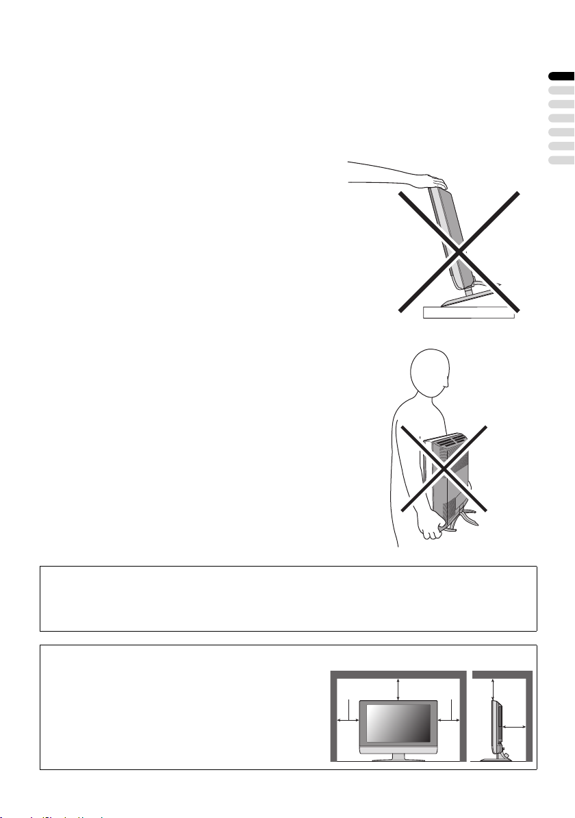
WARNING
• The TV may fall causing injuries. Hold the bottom of the
stand with your hand and tilt the TV up and down.
• Do not allow children to hang from the TV, place their
elbows on the TV or lean against the TV. Doing so may
cause the TV to fall over and lead to injuries.
CAUTION
• The TV screen may be damaged if the TV is carried as
shown in the diagram below.
The TV should always be carried by two people.
ENGLISH
Pixel defects
LCDs use collections of fine points (“pixels”) to display images. While there is no problem with
more than 99.99% of these pixels, please understand that a very small number of pixels may not
light, or may light all the time.
Distance recommendations
Avoid improper installation and never position the unit
where good ventilation is impossible.
When installing this TV, distance recommendations
must be maintained between the set and the wall, as well
as inside a tightly enclosed area or piece of furniture.
Keep to the minimum distance guidelines shown for
safe operation.
150 mm 150 mm
200 mm 200 mm
50 mm
1
Page 25

Failure to take the following precautions may cause damage to the television
or remote control.
DO NOT block the TV’s ventilation openings or holes.
(If the ventilation openings or holes are blocked by a newspaper or cloth, etc., the heat may not be
able to get out.)
DO NOT place anything on top of the TV.
(such as cosmetics or medicines, flower vases, potted plants, cups, etc.)
DO NOT allow objects or liquid into the cabinet openings.
(If water or liquid is allowed to enter this equipment, fire or electric shock may be caused.)
DO NOT place any naked flame sources, such as lighted candles, on the TV.
DO NOT subject the TV to direct sunlight.
The surface of the TV screen is easily damaged. Be very careful with it when handling the TV.
Should the TV screen become soiled, wipe it with a soft dry cloth. Never rub it forcefully.
Never use any cleaner or detergent on it.
If there is a fault, unplug the unit and call a service technician. Do not attempt to repair it yourself
or remove the rear cover.
Cleaning the screen
The screen is coated with a special thin film to reduce reflection. If this film is damaged, uneven
colors, discoloration, scratches, and other problems that cannot be repaired may occur. Pay
attention to the following when handling the screen.
• Do not use glue or adhesive tape on the screen.
• Do not write on the screen.
• Do not allow the screen to come in contact with any hard objects.
• Do not allow condensation to form on the screen.
• Do not use alcohol, thinner, benzene or other solvents on the screen.
• Do not rub the screen hard.
CAUTION:
• Operate only from the power source specified (AC 110 – 240 V, 50/60 Hz) on the unit.
• Avoid damaging the AC plug and power cord.
• When you are not using this unit for a long period of time, it is recommended that you disconnect
the power cord from the main outlet.
2
Page 26

CONTENTS
Setting up your TV ...................................4
Installation.................................................. 4
Using the stand .......................................... 4
Removing the terminal cover ..................... 5
Connecting the aerial and video cassette
recorder (VCR) ....................................... 6
Connecting the power cord to the AC
outlet....................................................... 7
Putting the batteries into the remote
control..................................................... 7
Initial settings ............................................. 7
T-V LINK functions................................... 10
TV buttons and functions......................12
Turn the TV on from standby mode ......... 12
Choose a TV channel .............................. 12
Watch images from external devices....... 12
Adjust the volume .................................... 13
Using the Menu........................................ 13
Remote control buttons and
functions..............................................14
Turn the TV on or off from standby mode
Choose a TV channel and watch images
from external devices ........................... 15
Adjust the volume .................................... 16
Information function ................................. 16
ZOOM function......................................... 17
3D SOUND function ................................. 18
Return to TV channel instantly................. 18
Favourite channel function....................... 19
Operating a JVC brand VCR or DVD
player.................................................... 20
... 14
Teletext function ....................................21
Basic operation ........................................ 21
Using the List Mode ................................. 21
Hold.......................................................... 22
Sub-page ................................................. 22
Reveal...................................................... 22
Size .......................................................... 22
Index ........................................................ 23
Cancel...................................................... 23
Using the TV’s menu..............................24
Basic operation ........................................ 24
PICTURE menu ......................................25
PICTURE MODE...................................... 25
BRIGHT-1 ................................................ 25
CONTRAST ............................................. 25
BRIGHT-2 ................................................ 25
SHARP..................................................... 25
COLOUR.................................................. 25
HUE.......................................................... 25
COLOUR TEMP....................................... 25
FEATURES .............................................. 26
SOUND menu ......................................... 28
STEREO / I • II ......................................... 28
BASS........................................................ 28
TREBLE ................................................... 28
BALANCE ................................................ 28
3D SOUND............................................... 28
FEATURES menu................................... 29
SLEEP TIMER ......................................... 29
CHILD LOCK............................................ 29
APPEARANCE......................................... 30
BLUE BACK ............................................. 30
FAVOURITE SETTING ............................ 31
SET UP menu ......................................... 32
AUTO PROGRAM.................................... 32
EDIT/MANUAL ......................................... 32
LANGUAGE ............................................. 36
DECODER (EXT-2).................................. 36
EXT SETTING.......................................... 37
Displaying a computer screen.............. 40
Connecting to the computer ..................... 40
Watching images from a computer ..........40
Table of signals for each type of
computer............................................... 40
Additional preparation .......................... 41
Connecting external equipment ...............41
CH/CC numbers ..................................... 44
Troubleshooting ....................................46
Specifications ........................................49
ENGLISH
3
Page 27
Setting up your TV
• When you install the TV on the wall, only use a JVC wall mounting unit (optional) which is
designed for this TV.
• Make sure that the TV is installed on the wall by a skilled installer.
Installation
Cautions for installation
• Install the TV in a corner on a wall or on the floor so as to keep cords out of the way.
• The TV will generate a slight amount of heat during operation. Ensure that sufficient space is
available around the TV to allow satisfactory cooling. See “Distance recommendations” on
page 1.
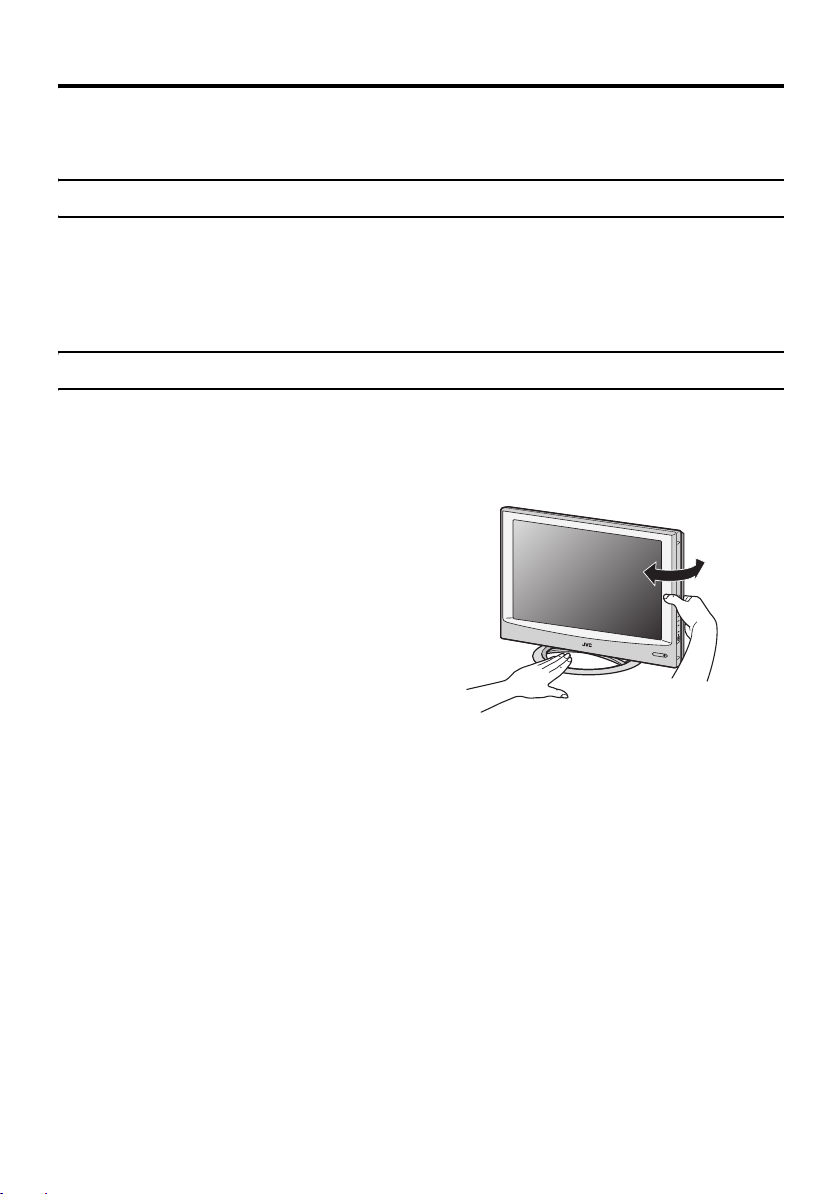
Using the stand
This TV comes with a table top stand already attached.
This stand can be used to adjust the direction of the TV screen to the left or right.
Rotate the TV to the left and right:
While holding the bottom of the stand with one
hand, use your other hand to hold the edge of
the panel and slowly adjust the direction of the
TV screen.
4
Page 28
Setting up your TV
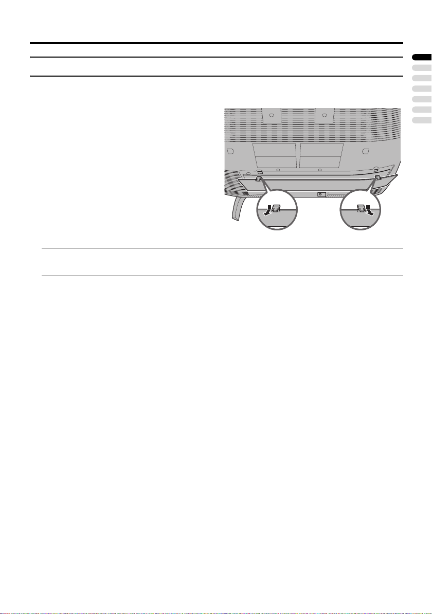
Removing the terminal cover
There are connection terminals behind the cover on the rear of the TV. Remove the cover before
connecting an antenna or VCR.
Remove the cover by removing the hooks.
When replacing the cover, place the side of the
cover against the TV and insert the hooks.
• Leave the cover off if they do not fit properly. Do not force to replace the cover. Doing so may
cause damage to the connection cables and the cover.
ENGLISH
5
Page 29
Setting up your TV
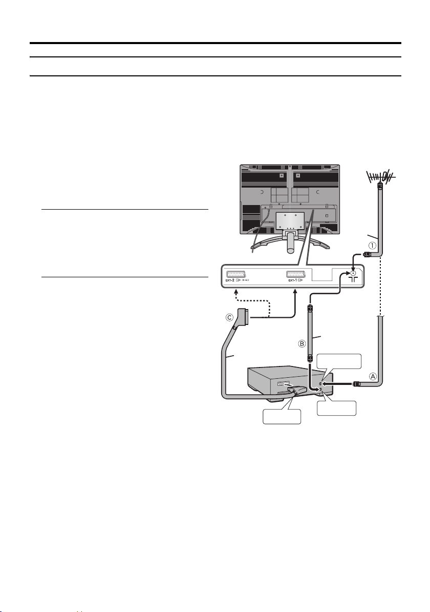
Connecting the aerial and video cassette recorder (VCR)
• The connecting cables are not provided.
• For further details, refer to the manuals provided with the devices to be connected.
Caution
• Turn off all the equipment including the TV before connecting anything.
If you are connecting a VCR,
follow A → B → C in the diagram
opposite.
If you are not connecting a VCR,
follow 1.
without terminal covers
Aerial
To use the T-V LINK functions, you must
have a T-V LINK compatible VCR
connected by a SCART cable C to the EXT2 terminal on the TV. For details about T-V
LINK functions, see “T-V LINK functions”
on page 10.
• You can watch a video using the VCR
without doing C. For details, see your
VCR instruction manual.
• To connect more equipment, please see
“Connecting external equipment” on
page 41.
• If you connect a decoder to a T-V LINK
compatible VCR, set the DECODER
(EXT-2) function to ON. For details, see
“DECODER (EXT-2)” on page 36.
Otherwise, you will not be able to watch
scrambled channels.
21-pin
SCART
Cable
VCR
AV IN/OUT
Terminal
75-ohm
Coaxial
Cable
To Aerial
Input
To Aerial
Output
75-ohm
Coaxial
Cable
6
Page 30
Setting up your TV
s
Connecting the power cord to
the AC outlet
Insert the AC plug on the power cord from
the TV into an AC outlet.
Caution
• Operate only from the power source
specified (AC 110 – 240 V, 50/60 Hz)
on the unit.
• Remove the AC plug from the outlet to
completely disconnect the TV from the
power supply.
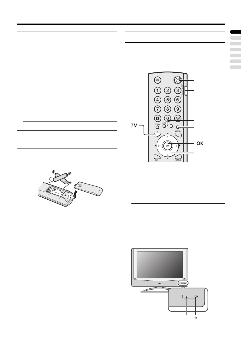
Putting the batteries into the
remote control
Use two AA/R6 dry cell batteries.
Insert the batteries from the - end, making
sure the + and - polarities are correct.
• Follow the warnings printed on the
batteries.
• Battery life is about six months to one
year, depending on how much you use the
remote control.
• The batteries we supply are only for
setting up and testing your TV, please
replace them as soon as you need to.
• If the remote control does not work
properly, replace the batteries.
Initial settings
When the TV is first turned on, it goes into
the initial settings mode, and you will see the
JVC logo. Follow the instructions on the
screen display to make the initial settings.
# button
VCR/TV/DVD
switch
Yellow button
Blue button
7 button
1 Make sure to set the VCR/TV/DVD
switch on the remote control to the
TV position
• You cannot turn the TV on when the
VCR/TV/DVD switch is set to the
VCR or DVD position.
2 Press the # button on the remote
control
The TV turns on from standby mode and
the JVC logo is displayed.
• Check that the AC plug on the power
cord from the TV is connected to AC
outlet.
ENGLISH
Remote control
sensor
Power lamp
7
Page 31

Setting up your TV
• If the JVC logo does not appear this is
because your TV has already been
turned on for the first time:
use the “LANGUAGE” and “AUTO
PROGRAM” functions to make the
initial settings. For details, see “SET
UP menu” on page 32.
3 Press the a button
The LANGUAGE menu appears.
> LANGUAGE
OK
D0002(E)-EN
4 Press the 6 buttons to choose
ENGLISH. Then press the a
button
The on-screen display will then be in
English.
The COUNTRY menu appears as a submenu of the AUTO PROGRAM function.
There are two COUNTRY menus.
Pressing the yellow button changes the
COUNTRY menu as follows:
> COUNTRY
OK
> COUNTRY
START
MORE
5 Press the 5 and 6 buttons to
choose the country where you are
6 Press the blue button to start the
AUTO PROGRAM function
The AUTO PROGRAM menu appears
and received TV channels are
automatically stored in the programme
numbers (PR).
>> AUTO PROGRAM
CH 28
14%
OK
D0004-EN
• To cancel the AUTO PROGRAM
function:
Press the b button.
After the TV channels have been
registered in the programme
numbers (PR), the EDIT menu
appears
> EDIT
D0038-EN
PR ID
AV
01
02
03
04
05
06
07
08
09
OK
MOVE
BBC1
CH/CC
CH
CH
CH
CH
CH
CH
CC
CC
CC
ID
INSERT
21
22
23
24
25
26
01
02
03
MANUAL
DELETE
• If you want to, you can now edit the
programme numbers (PR) using the
EDIT/MANUAL function. For details,
see “EDIT/MANUAL” on page 32.
• If you do not want to edit programme
numbers (PR), go to the next step.
OK
D0003-EN
START
MORE
8
Page 32

7 Press the a button to display the
T-V LINK menu
T-V LINK
DOWNLOAD TV RECORDING DEVICE
Setting up your TV
EXIT
OK
D0005
-EN
If you do not have a T-V LINK
compatible VCR connected:
Press the b button to exit the T-V LINK
menu.
The T-V LINK menu disappears.
If you have a T-V LINK compatible
VCR connected to the EXT-2
terminal:
Follow the operating procedure
“Downloading the data to VCR” on
page 10 to transmit the Programme
number (PR) data.
Now, the initial settings are complete,
and you can watch the TV
• If your TV can detect the TV channel
name from the TV channel broadcast
signal, the TV channel name is assigned
to the programme number (PR) to which
the TV channel has been set. However,
which TV channels are set to which
programme numbers (PR) will depend on
the area in which you live.
• If a TV channel you want to view is not
set to a programme number (PR), you can
set it using the MANUAL function. For
details, see “EDIT/MANUAL” on
page 32.
• The AUTO PROGRAM function does not
set the programme number PR 0 (AV) for
your video cassette recorder. You will
need to set this using the MANUAL
function.
ENGLISH
9
Page 33

Setting up your TV
Downloading the data to VCR
You can transmit to the latest Programme
numbers (PR) data to a VCR with the T-V
LINK function.
Caution
• This only works when a T-V LINK
compatible VCR is connected to the
EXT-2 terminal.
• This only works when the T-V LINK
menu is being displayed.
T-V LINK
DOWNLOAD TV RECORDING DEVICE
EXIT
OK
D0005
-EN
1 Turn on the VCR
2 Press the a button
The data transmission begins.
TV RECORDING DEVICE
TRANSFER. . . . .
D0037
-EN
The T-V LINK menu disappears once the
data transmission ends.
When the T-V LINK menu is
changed over to another menu:
The TV has finished its menu. This new
menu is operated from the VCR. See the
VCR instruction manual for what to do
next.
If “FEATURE NOT AVAILABLE”
appears at the T-V LINK menu:
Check the following three items. Then
press the 2 button to retry data
transmission.
• Has a T-V LINK compatible VCR
been connected to the EXT-2
terminal?
• Has the VCR power been turned on?
• Does the SCART cable that is
connected to the EXT-2 terminal to TV LINK compatible VCR have all its
proper connections?
T-V LINK functions
When you have a T-V LINK compatible
VCR connected to the EXT-2 Terminal on
the TV, it is easier to set up the VCR and to
view videos. T-V LINK uses the following
features:
To use T-V LINK functions:
A “T-V LINK compatible VCR” means a
JVC video cassette recorder with the T-V
LINK logo, or with one of the following
logos. However, these VCRs may support
some or all of the features described earlier.
For details, see your VCR instruction
manual.
“Q-LINK” (a trademark of Panasonic
Corporation)
“Data Logic” (a trademark of Metz
Corporation)
“Easy Link” (a trademark of Phillips
Corporation)
“Megalogic” (a trademark of Grundig
Corporation)
“SMARTLINK” (a trademark of Sony
Corporation).
10
Page 34

Setting up your TV
Pre-set download
The VCR will automatically download the
registered data on the TV channels from the
TV. This means you do not need to set up the
program channels on your VCR manually.
The preset download function automatically
begins when the initial setting is complete or
whenever you carry out the AUTO
PROGRAM or EDIT/MANUAL functions.
You can also carry out this function using
your VCR controls.
When “FEATURE NOT AVAILABLE” is
displayed:
If “FEATURE NOT AVAILABLE” is
displayed, the download was not performed
correctly. Before trying to download again,
check that:
• the VCR power is turned on
• the VCR is T-V LINK compatible
• the VCR is connected to the EXT-2
terminal
• the SCART cable is fully wired.
Direct Rec
“What You See Is What You Record”
You can easily record to VCR the images
that you are watching on the TV.
For details, read the manual for your VCR.
Use your VCR controls. “DEVICE IS
RECORDING” is displayed.
In the following situations, the VCR
will stop recording if the TV is turned
off, if the TV channel or input is
changed, or if the menu is displayed
on the TV:
• when recording images from an external
device connected to the TV (for example
a camcorder)
• when recording a TV channel after it has
been unscrambled on a decoder
• when recording a TV channel by using the
TV’s output because the VCR’s own
tuner cannot properly receive that
channel.
You cannot carry out Direct Rec using your
TV’s control.
Generally, the VCR cannot record a TV
channel that it cannot receive properly on its
own tuner, even if you can view that TV
channel on the TV. However, some VCRs
can record a TV channel by using the TV’s
output if that channel can be viewed on the
TV. For details, see your VCR instruction
manual.
When the VCR is not ready, the following
messages are displayed.
ERROR
MESSAGE
NO
RECORDING
NO
RECORDING
POSSIBLE
NO
RECORDING,
MEDIA
PROBLEM
NO
RECORDING,
DEVICE BUSY
Cause and
countermeasure
The VCR is not able to
record.
Check the VCR.
The TV input is set to EXT-4
or PC. Since the EXT-4
picture or PC picture cannot
be output to EXT-2, DIRECT
REC is not possible.
The recording device is not
ready to record. Check the
VCR tape.
The recording device cannot
record as it is recording or
playing. Check the VCR.
Refer to the VCR instruction manual.
ENGLISH
11
Page 35

TV buttons and functions
Turn the TV on from standby
mode
Press the A button or the P p
buttons to turn the TV on from
standby mode.
When the TV is turned on, the power lamp
lights blue.
To turn the TV off:
Press the A button again.
The power lamp goes off.
Caution
•The A button on the TV does not fully
isolate the TV from the AC supply. If
you are not going to use the TV for a
long period, be sure to disconnect the
AC plug from the AC socket.
Choose a TV channel
Press the P p buttons to choose a
programme number (PR) or an EXT
terminal
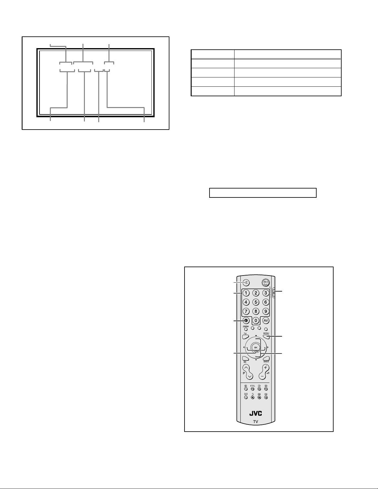
Refer to the pages in parentheses for details.
1 Remote control sensor
2 Power lamp (page 7)
3 TV/AV button (page 12)
4 MENU/OK button (pages 13, 24)
5 P p buttons (page 12)
6 r (Volume) q buttons (page 13)
7 A (Stand by) button (page 12)
8 Headphone jack (mini jack) (page 41)
12
Watch images from external
devices
Press the TV/AV button to choose an
EXT terminal
TV mode EXT modes
Last
Programme
number
or
or
Page 36

Adjust the volume
Press the r (Volume) q buttons
The volume level indicator appears.
TV buttons and functions
Using the Menu
Use the MENU/OK button
Refer to “Using the TV’s menu” (see
page 24) for details of using the menu.
ENGLISH
13
Page 37

Remote control buttons and functions
1 Muting button
2 Number buttons
3 Information button
1
2
3
4
5
6
7
8
~
!
@
#
$
%
^
4 c button
5 i button
6 b button
7 7 buttons
8 g (Text) button
9 p p buttons
0 VCR/DVD/Teletext control buttons
- p buttons
= d (Favourite) button
~ # (Standby) button
! VCR/TV/DVD switch
@ G button
# Colour buttons
$ H button
% a button
^ b button
& r (Volume) q buttons
Turn the TV on or off from
standby mode
14
9
0
=
&
Press the # (standby) button to turn
the TV on or off
When the TV is turned on, the power lamp
lights blue.
• The power can be turned on by pressing
the b button, p p buttons or Number
buttons.
To turn the TV on or off, set the VCR/TV/
DVD switch on the remote control to the
TV position and press the # button.
If the VCR/TV/DVD switch on the remote
control is set to a position other than TV,
the TV will not be turned on or off even if
the # button is pressed.
Page 38

Remote control buttons and functions
Choose a TV channel and
watch images from external
devices
Use the number buttons:
Enter the programme number (PR)
of the channel using the number
buttons.
Example:
•PR 6 → press 6
• PR 12 → press 1 and 2
Use the p p buttons:
Press the p p buttons to
choose the programme number
(PR) you want or an EXT terminal.
Use the AV button:
Press the AV button to choose an
EXT terminal.
TV mode EXT modes
Programme
numbers
PR 1 – PR 99
or
or
• Since this TV is designed to make full use
of the resolution of the original video
source, the motion may appear unnatural
when the video source is input with
progressive-scanning component signals.
If this happens, change the output setting
of the connected device to interlacescanning component signal output. See
the instructions that came with the device
for more information.
• The PC sound is the same as the EXT-3
sound.
To return to a TV channel:
Press the b button, the 6 buttons or the
number buttons.
To use the programme number PR 0
(AV):
When the TV and VCR are connected only
by the aerial cable, choosing the programme
number PR 0 (AV) allows you to view
images from the VCR. Set the VCR RF
channel to the programme number PR 0
(AV) manually. For details, see “EDIT/
MANUAL” on page 32.
Pressing the G button changes the choice as
follows:
TV mode EXT modes
Programme
numbers
PR 1 – PR 99
PR 0
EXT-1
EXT-2
or
ENGLISH
• You can choose a video input signal from
the S-VIDEO signal (Y/C signal) and
regular video signal (composite signal).
For details, see “S-IN (S-VIDEO input)”
on page 37.
• If you do not have a clear picture or no
colour appears, change the colour system
manually. See “COLOUR SYSTEM” on
page 26.
• If you choose an EXT terminal with no
input signal, the EXT terminal number
becomes fixed on the screen.
EXT-3
or
EXT-4
• The VCR sends its playback image along
the aerial cable as an RF (radio frequency)
signal.
• Also see your VCR instruction manual.
15
Page 39

Remote control buttons and functions
Adjust the volume
Press the r q buttons to adjust
the volume.
The volume level indicator appears and the
volume changes as you press the r q
buttons.
Muting the sound
Press the l (muting) button to
turn off the sound.
Pressing the l (muting) button again
restores the previous volume level.
Information function
You can see the channel number of the
programme you are watching, the current
time or the PR LIST.
From the PR LIST, you can choose a channel
or EXT terminal.
Press the h (Information) button to
display the information you want to
see.
Pressing the h (Information) button changes
the display as follows:
PR LIST
PR ID
AV
BBC1
01
02
03
04
05
06
07
OK
+8-8
D0011-EN
Channel number display:
The channel number and channel name
(when the channel name is registered) of the
programme you are watching or the EXT
terminal number is displayed.
Channel number display
12 : 00
No indication
Time display:
The current time of the teletext data is
displayed.
If the TV has not received a TV channel that
has teletext programmes since it was turned
on, the time display is blank. To view the
current time, choose a TV channel that has
teletext programmes.
• An incorrect current time is sometimes
displayed when watching videos.
PR LIST:
The programme number (PR) and EXT
terminal list is displayed.
Pressing the a button after choosing the
programme number (PR) or EXT terminal
with the 7 buttons will display the
chosen programme or EXT terminal.
• For programme numbers (PR) for which
the CHILD LOCK function is set, the n
(CHILD LOCK) mark is displayed. For
details see “CHILD LOCK” on page 29.
• For programme numbers (PR) which is
registered as a favourite channel, the d
(favourite) mark is displayed. For details
see “Favourite channel function” on
page 19.
16
Page 40

Remote control buttons and functions
ZOOM function
You can change the screen size according to
the picture aspect ratio. Choose the optimum
one from the following ZOOM modes.
• The ZOOM mode is fixed at FULL when
you are using the TV as a PC screen.
AUTO:
When a WSS (Wide Screen Signalling)
signal, which shows the aspect ratio of the
picture, is included in the broadcast signal or
the signal from an external device, the TV
automatically changes the ZOOM mode to
16:9 ZOOM mode or FULL mode according
to the WSS signal.
If a WSS signal is not included, the picture is
displayed according to the ZOOM mode set
with the 4:3 AUTO ASPECT function.
• For details of the 4:3 AUTO ASPECT
function, see “4:3 AUTO ASPECT” on
page 27.
• When the AUTO (WSS) mode does not
function correctly due to poor WSS signal
quality or when you want to change the
ZOOM mode, press the c button
and change to another ZOOM mode.
REGULAR:
Use to view a normal picture (4:3 aspect
ratio) as this is its original shape.
PANORAMIC:
This stretches the left and right sides of a
normal picture (4:3 aspect ratio) to fill the
screen, without making the picture appear
unnatural.
• The top and bottom of the picture are
slightly cut off.
14:9 ZOOM:
This zooms up the wide picture (14:9 aspect
ratio) to the upper and lower limits of the
screen.
16:9 ZOOM:
This zooms up the wide picture (16:9 aspect
ratio) to the full screen.
16:9 ZOOM SUBTITLE:
This zooms up the wide picture (16:9 aspect
ratio) with subtitles to the full screen.
FULL:
This uniformly stretches the left and right
sides of a normal picture (4:3 aspect ratio) to
fill the wide TV screen.
• For 16:9 aspect ratio pictures that have
been squeezed into a normal picture (4:3
aspect ratio), use the FULL mode to
restore the picture to its original shape.
Choose the ZOOM mode
1 Press the c button to display
the ZOOM menu
ZOOM
AUTO
REGULAR
PANORAMIC
14:9 ZOOM
16:9 ZOOM
16:9 ZOOM SUBTITLE
FULL
OK
D0009-EN
2 Press the 6 buttons to choose a
ZOOM mode. Then press the a
button
The picture expands and the chosen
ZOOM mode is displayed in about 5
seconds.
• The ZOOM mode may be
automatically changed by the control
signal from an external device. When
you want to return to the previous
ZOOM mode, choose the ZOOM
mode again.
ENGLISH
17
Page 41

Remote control buttons and functions
Adjusting the visible area of the
picture
If subtitles or the top (or bottom) of the
picture are cut off, you can adjust the visible
area of the picture manually.
1 Press the c button
The ZOOM menu appears.
2 Press the a button to display the
ZOOM mode indicator
The indicator appears.
16 : 9 ZOOM
D0010-EN
3 While it is displayed, press the 6
buttons to change the position of
the picture
• You cannot adjust the visible area in
REGULAR or FULL mode.
The visible area adjustment is saved even
after the TV channel is changed.
However, it is cancelled if the following
operations are performed.
• The power is turned off/on
• The ZOOM mode is changed
• g (Text) button is pressed
• The TV is switched between TV mode
and EXT mode
MONO:
Select the MONO mode, when you listen to
the mono sound.
You can enjoy the sound for a wider
audience similar to stereo sound.
OFF:
The 3D SOUND function switches off.
• You can choose the 3D SOUND mode
with the “SOUND menu” (see page 28).
Return to TV channel instantly
You can return to a TV channel instantly.
Press the b button
The TV returns to the TV mode and a TV
channel appears.
3D SOUND function
You can enjoy sounds with a wider
ambience.
• This function does not work for the sound
from headphones.
Press the i button to select one of
3D SOUND modes
ON:
When you listen to stereo sound, please
select ON mode.
You can enjoy sound similar to the
experience at the theatre.
18
Page 42

Remote control buttons and functions
Favourite channel function
You can register your favourite TV channels
(PR 1 – PR 99) in the number buttons 1 to 4.
After registering, the channel can be called
by pressing the d (favourite) button and a
number button 1 to 4.
Favourite channel registration
1 In the normal screen, choose a TV
channel (PR 1 – PR 99) that you
want to register
For details, refer to “Choose a TV channel
and watch images from external devices”
on page 15.
2 Press and hold the d (favourite)
button for three seconds or more
Then “SET 1-4?” appears on the screen.
3 Press one of the number buttons 1
to 4
The current channel is registered in the
pressed number button.
After “PROGRAMMED!” appears on the
screen, the favourite channel icon appears
at the top-right of the screen.
• If the channel you are trying to register
is already registered in one of the other
number buttons 1 to 4, “NOT
AVAILABLE” appears on the screen.
• Channels locked with the CHILD
LOCK function cannot be registered.
• If AUTO PROGRAM is performed,
the registered favourite channels are
reset.
Calling the favourite channel
1 In the normal screen, press the d
(favourite) button
Then “FAVORITE1-4?” appears.
2 Press one of the number buttons 1
to 4
The called favourite channel appears on
the screen.
• If a number button in which no
channel is registered is pressed, “NO
MEMORY” appears on the screen.
Setting the picture effect
When a favourite channel has been chosen
with the d (favourite) button and number
buttons 1 to 4, picture effect settings can be
memorised for each favourite channel by
setting the picture effects in the PICTURE
menu (see page 25).
The following items in the PICTURE menu
(see page 25) are memorised.
PICTURE MODE
BRIGHT-1
CONTRAST
BRIGHT-2
SHARP
COLOUR
HUE
COLOUR TEMP.
DIGITAL VNR
COLOUR SYSTEM
The last setting made for each item is
memorised.
ENGLISH
• When you want to delete a favourite
channel, delete the set channel and set
contents with FAVOURITE SETTING
(see page 31) in the FEATURES menu.
19
Page 43

Remote control buttons and functions
Operating a JVC brand VCR or
DVD player
These buttons will operate a JVC brand VCR
or DVD player. Pressing a button that looks
the same as the device’s original remote
control button has the same effect as the
original remote control.
1 Set the VCR/TV/DVD Switch to the
VCR or DVD position
VCR:
When you are operating the VCR, set the
switch to the VCR position.
• You can turn the VCR on or off with
the # (standby) button.
DVD:
When you are operating the DVD player,
set the switch to the DVD position.
• You can turn the DVD player on or off
with the # (standby) button.
• You can also press the H or
T button and display the
DVD disc menu screen, and then
operate by pressing the 7
buttons.
2 Press the VCR/DVD Control Button
to control your VCR or DVD player
• If your device is not made by JVC,
these buttons will not work.
• Even if your device is made by JVC,
some of these buttons may not work,
depending on the device you are using.
• You can use the p buttons to choose
a TV channel the VCR will receive, or
choose the chapter the DVD player
plays back.
• Some models of DVD player use the
p buttons for both operating the fast
forward/backward functions and for
choosing the chapter. In this case, the
253 buttons do not work.
You cannot turn the TV on or off when the
VCR/TV/DVD switch is set to the VCR or
DVD position.
When you turn the TV on or off, set the
VCR/TV/DVD switch to the TV position.
20
Page 44

Teletext function
VCR/TV/
DVD
4 Choose a teletext page by pressing
the p p buttons, number buttons
or colour buttons
To return to the TV mode:
Press the b button or g (Text) button.
Basic operation
1 Choose a TV channel with a teletext
broadcast
2 Set the VCR/TV/DVD switch to the
TV position
3 Press g (Text) button to display
the teletext
Pressing g (Text) button changes the
mode as follows:
TEXT
---
TEXT
---
TV mode Text mode
• If you have trouble receiving teletext
broadcasts, consult your local dealer or
the teletext station.
• The ZOOM function will not work in
the TV and text mode or Text mode.
• You cannot operate menus when
viewing a teletext programme.
• Language display depends on the
country which was set on the
COUNTRY menu. If characters on a
Teletext programme do not appear
properly, change the COUNTRY
setting to other country’s. To change
the COUNTRY setting, perform steps
1 and 2 of the “AUTO PROGRAM”
procedure on page 32 and then press
the a button.
Using the List Mode
You can store the numbers of your favourite
teletext pages in memory and call them up
quickly using the colour buttons.
To store the page numbers:
1 Press B button to go into the
List mode
The page numbers you have stored are
displayed at the bottom of the screen.
ENGLISH
21
Page 45

Teletext function
2 Press a colour button to choose a
position. Then press the number
buttons to enter the page number
3 Press and hold down the A (Store)
button
The four page numbers blink white to
show that they are stored in memory.
To call up a stored page:
1 Press the B button to enter the
List mode
2 Press a colour button having a
stored page
To exit the List mode:
Press the B button again.
Hold
You can hold a teletext page on the screen for
as long as you want, even while several other
teletext pages are being received.
Press the C (Hold) button
Hold indication
Sub-page
Some teletext pages include sub-pages that
are automatically displayed.
You can hold any sub-page, or view it at any
time.
1 Press the d (Favourite) button to
operate the Sub-page function
2 Press the Number buttons to enter
a sub-page number
Example:
• 3rd sub-page → press 0, 0, 0 and 3.
To cancel the Sub-page function:
Press the d (Favourite) button again.
Reveal
Some teletext pages include hidden text
(such as answers to a quiz).
You can display the hidden text.
Each time you press the E (Reveal)
button, text is hidden or revealed
Size
You can double the height of the teletext
display.
Press the F (Size) button
To cancel the Hold function:
Press C (Hold) button again.
22
Page 46

Index
You can return to the index page instantly.
Press the G (Index) button
Returns to page 100 or a previously specified
page.
Cancel
You can search for a teletext page while
watching TV.
1 Press the number button to enter a
page number, or press a colour
button
The TV searches for a teletext page.
2 Press H (Cancel) button
The TV programme appears. When the
TV finds the teletext page, its page
number appears in the upper left of the
screen.
3 Press H (Cancel) button to return
to a teletext page when the page
number is on the screen
• The TV mode cannot be resumed by
pressing the H (Cancel) button. To
return to the TV mode press b.
Teletext function
ENGLISH
23
Page 47

Using the TV’s menu
PICTURE
PICTURE
This TV has a number of functions you can
operate using menus. To use all your TV’s
functions, you need to understand the basic
menu operating techniques fully.
Buttons used to operate the menus
Basic operation
1 Press the H button to display
the menu bar
D0105-EN
2 Press the 5 buttons to choose
the menu you want to use and then
press the a button
Types of menu
PICTURE menu
D0106
Choose to set the screen
settings.
SOUND menu
D0107
Choose to set the sound settings.
FEATURES menu
D0108
Choose to set the sleep timer
and child lock settings.
SET UP menu
Choose to edit the channels or
D0109
set the display language
settings.
• The menu will disappear after about
one minute if no operation is
performed.
Operation with the buttons on the TV
You can also operate the menus using the
buttons on the front panel of the TV.
D1105-EN
Chosen
menu
3 Press the 6 buttons to choose
the item to be set, press the 5
buttons to set the item, and then
press the a button
If there are sub-menus, use the 7
buttons to operate them.
• Press the b button to return to
the previous menu.
• Press the b or H button to exit
from the menu.
• Some menu items may not be operated
or set depending on the TV status or
other menu item settings.
Menu items that cannot be operated or
set are displayed in grey in the menu
and cannot be chosen.
24
Chosen
menu name
TV/AV button
MENU/OK button
6 buttons
5 buttons
Page 48

PICTURE menu
PICTURE
PICTURE
STANDARD
PICTURE MODE
BRIGHT-1
CONTRAST
BRIGHT-2
SHARP
COLOUR
HUE
COLOUR TEMP.
FEATURES
OK
D0014
-EN
• While the PICTURE menu is displayed,
pressing the blue button will set the
BRIGHT-1, CONTRAST, BRIGHT-2,
SHARP, COLOUR, HUE settings to their
default settings.
• When watching the picture from EXT-1
to EXT-4 or the PC, picture effect settings
can be memorised for each external input
by setting the picture effects in the
PICTURE menu.
The following items in the PICTURE
menu are memorised.
PICTURE MODE
BRIGHT-1
CONTRAST
BRIGHT-2
SHARP
COLOUR
HUE
COLOUR TEMP.
DIGITAL VNR
COLOUR SYSTEM
The last setting made for each item is
memorised.
PICTURE MODE
You can choose one of three PICTURE
MODEs to adjust the picture settings
automatically.
BRIGHT:
Heightens contrast and sharpness.
STANDARD:
Standardizes picture adjustment.
SOFT:
Softens contrast and sharpness.
STANDARD
COOL
COOL
RESET
BRIGHT-1
You can adjust the back light.
2 : darker
3 : brighter
CONTRAST
You can adjust the picture contrast.
2 :lower
3 : higher
BRIGHT-2
You can adjust the picture brightness.
2 : darker
3 : brighter
SHARP
You can adjust the picture sharpness.
2 : softer
3 :sharper
COLOUR
You can adjust the picture colour.
2 : lighter
3 :deeper
HUE
You can adjust the picture tint.
2 : reddish
3 :greenish
• You can change the HUE setting (picture
hue) when the colour system is NTSC
3.58, or NTSC 4.43.
COLOUR TEMP.
You can select one of three COLOUR
TEMP. modes (three tones of white) to adjust
the white balance of the picture. Since white
is the colour which is used as a reference for
all the other colours, changing the COLOUR
TEMP. mode affects the appearance of all
the other colours on the screen.
ENGLISH
25
Page 49

PICTURE menu
COOL:
A bluish white. Using this mode when
watching bright pictures allows you to enjoy
a more vivid and bright picture.
NORMAL:
The normal white colour.
WARM:
A reddish white. Using this mode when
watching films allows you to enjoy colours
that are characteristic of films.
FEATURES
Choose FEATURES and press the a or 3
button to display the sub-menu.
> FEATURES
DIGITAL VNR
COLOUR SYSTEM
4:3 AUTO ASPECT
OK
D1015-EN
DIGITAL VNR
The DIGITAL VNR function cuts down the
amount of ‘noise’ (‘snow’ or interference) in
the original picture.
ON:
This function is turned on.
OFF:
This function is turned off.
AUTO(LOW)
COLOUR SYSTEM
The colour system is chosen automatically.
However, if the picture is not clear or no
colour appears, choose the colour system
manually.
1 Choose COLOUR SYSTEM. Then
press the a or 3 button
The sub-menu of the COLOUR SYSTEM
function appears.
>> COLOUR SYSTEM
AUTO
OK
D0016-EN
2 Press the 6 buttons to choose
the appropriate colour system.
Then press the a button
PAL:
PAL system
SECAM:
SECAM system
NTSC 3.58:
NTSC 3.58 MHz system
NTSC 4.43:
NTSC 4.43 MHz system
AUTO:
This function detects a colour system
from the input signal. You can only use
this when you are viewing a picture from
programme number PR 0 (AV), or an
EXT terminal.
• The AUTO function may not function
properly if you have poor signal quality.
If the picture is abnormal in the AUTO
function, choose another colour system
manually.
• When in the Programme numbers PR 0
(AV) to PR 99, you cannot choose NTSC
3.58 or NTSC 4.43.
• COLOUR SYSTEM cannot be chosen
when you are watching the PC picture.
26
Page 50

4:3 AUTO ASPECT
You can choose one of three ZOOM modes,
REGULAR, PANORAMIC or 14:9 ZOOM,
as the ZOOM mode for the normal picture
(4:3 aspect ratio).
1 Choose 4:3 AUTO ASPECT then
press the a button
>> 4:3 AUTO ASPECT
PANORAMIC
REGULAR
14:9 ZOOM
OK
D0017-EN
2 Press the 6 buttons to choose a
ZOOM mode
PICTURE menu
ENGLISH
27
Page 51

SOUND menu
SOUND
STEREO/
BASS
TREBLE
BALANCE
D0019
3D SOUND
OK
-EN
OFF
• When the headphones are connected, only
“STEREO / I • II” can be used.
STEREO / I • II
When you are viewing a bilingual broadcast
programme, you can choose the sound from
Bilingual I (Sub I) or Bilingual II (Sub II). If
you have poor reception on a stereo
broadcast, you can change from stereo to
mono sound so that you can hear the
broadcast more clearly and easily.
s: Stereo sound
v : mono sound
t : Bilingual I (sub I)
u : Bilingual II (sub II)
• The sound mode you can choose differs
depending on the TV programme.
• This function does not work in the EXT
modes.
BALANCE
You can adjust the volume balance between
the left and right speaker.
2 : turn the left speaker’s volume level up.
3 : turn the right speaker’s volume level up.
3D SOUND
You can enjoy Surround sound with a “live”
effect by using the 3D SOUND function.
• You can choose a 3D SOUND mode from
ON, MONO and OFF modes. For details,
see “3D SOUND function” on page 18.
• You can also operate the 3D SOUND
function with the i button. For details,
see “3D SOUND function” on page 18.
BASS
You can adjust the low tone of the sound.
2 : weaker
3 :strong
TREBLE
You can adjust the high tone of the sound.
2 : weaker
3 :strong
28
Page 52

FEATURES menu
FEATURES
SLEEP TIMER
CHILD LOCK
APPEARANCE
BLUE BACK
FAVOURITE SETTING
OK
D0023-EN
TYPE A
ON
SLEEP TIMER
You can set the TV to automatically turn off
after a set period of time.
1 Choose SLEEP TIMER. Then press
the a or 3 button
A Sub-menu of the SLEEP TIMER
function appears.
> SLEEP TIMER
0120
OFF
OK
D0024-EN
2 Press the 5 buttons to set the
period of time.
Then press the a button
You can set the period of time for up to
120 minutes (2 hours) in 10 minute steps.
• One minute before the SLEEP TIMER
function turns off the TV,
“GOODNIGHT!” appears.
• The SLEEP TIMER function cannot
be used to turn off the TV’s main
power.
• When the SLEEP TIMER function is
on, you can display the sub-menu of
the SLEEP TIMER function again to
confirm or change the remaining
period of time of the SLEEP TIMER
function. Press the a button to leave
the menu after confirming or changing
the remaining time.
To cancel the SLEEP TIMER
function:
Press the 2 button to set the period of
time to “OFF”.
CHILD LOCK
When there is a TV channel you do not want
your children to watch, you can use the
CHILD LOCK function to lock out the TV
channel. Even when a child chooses a
programme number (PR) for a locked TV
channel the screen will change to blue and
display n (CHILD LOCK) so the TV channel
cannot be viewed. Unless you enter a pre-set
ID number by a special operation, the lock
cannot be released and the child cannot view
the TV channel.
To set the CHILD LOCK function
1 Choose CHILD LOCK, then press
the 0 button
“SET ID NO.” (ID number setting screen)
appears.
>> SET ID NO.
040
0
OK
D0025-EN
2 Set the ID number to your liking
1 Press the 6 buttons to choose
a number.
2 Press the 5 buttons to move
the cursor.
3 Press the a button
The Sub-menu of CHILD LOCK appears.
>> CHILD LOCK
D0026-EN
PR ID
AV
01
02
03
04
05
06
07
08
09
OK
BBC1
CH/CC
CH
CH
CH
CH
CH
CH
CC
CC
CC
21
22
23
24
25
26
01
02
03
LOCK
ENGLISH
29
Page 53

FEATURES menu
4 Press the 6 buttons to choose a
TV channel
Every time you press the 6 buttons, the
Programme number (PR) changes, and the
picture of the TV channel registered in the
Programme number (PR) is displayed on
the screen.
5 Press the blue button and set the
CHILD LOCK function.
Then press the a button
n (CHILD LOCK) appears and the TV
channel is locked.
To reset the CHILD LOCK function:
Press the blue button again.
n (CHILD LOCK) disappears.
To disable easy resetting of the CHILD
LOCK function, the menu disappears if
you choose the CHILD LOCK function
and press the a button.
To view a locked TV channel
1 Choose a programme number (PR)
of a locked TV channel with the
number buttons or PR LIST
The screen changes to blue and the n
(CHILD LOCK) appears. You cannot
view the TV channel.
5
D0027-EN
2 Press the h (Information) button to
display “ID NO.” (ID No. input
screen)
5
ID NO. :
D0028-EN
3 Press the number buttons to enter
the ID number
The lock is temporarily released so you
can view the TV channel.
If you have forgotten the ID
number:
Perform step 1 of “To set the CHILD
LOCK function”. After confirming the ID
number, press the b button to exit the
menu.
• Even if you reset the lock temporarily,
it does not mean that the CHILD
LOCK function set for the TV channel
is cancelled. The next time anyone
tries to view the TV channel, it will be
locked again.
• When you want to cancel the CHILD
LOCK function, you must perform the
operation “To set the CHILD LOCK
function” again.
• To stop it being easy to choose the
programme number (PR) of a locked
TV channel, the programme number
(PR) has been set so that it cannot be
chosen with the 6 buttons or the
buttons of the TV.
• To stop it being easy to reset the lock,
“ID NO.” (ID No. input screen) is set
so that it cannot appear unless you
press the h (Information) button.
APPEARANCE
Press the 5 button and choose the format
in which the channel number is displayed
from two types: TYPE A and TYPE B.
BLUE BACK
You can set the TV to automatically change
to a blue screen and mute the sound if the
signal is weak or absent, or when there is no
input from an external device.
ON:
This function is turned on.
OFF:
This function is turned off.
30
Page 54

FAVOURITE SETTING
Chose when deleting the favourite channels
registered in the buttons 1 to 4.
1 Choose FAVOURITE SETTING,
then press the a or 3 button
The FAVOURITE SETTING menu
appears.
FAVOURITE SETTING
FEATURES menu
ENGLISH
1
2
3
4
OK
D0112-EN
PR
PR 01
PR
PR
07
01
01
RESET
2 Press the 6 buttons and chose
the favourite channel that you want
to delete
3 Press the blue button
The chosen favourite channel and set
contents are deleted.
• For details of the favourite channels, see
“Favourite channel function” on page 19.
31
Page 55

SET UP menu
SET UP
AUTO PROGRAM
EDIT/MANUAL
LANGUAGE
DECODER(EXT-2)
EXT SETTING
D0029
-EN
OK
OFF
AUTO PROGRAM
You can again perform the AUTO
PROGRAM function TV channel automatic
registration which was performed in the
“Initial settings” (page 7).
1 Choose AUTO PROGRAM, then
press the a or 3 button
The COUNTRY menu appears as a submenu of the AUTO PROGRAM function.
There are two COUNTRY menus.
Pressing the yellow button changes the
COUNTRY menu as follows:
> COUNTRY
OK
> COUNTRY
OK
D0003-EN
2 Press the 5 and 6 buttons to
choose the country where you are
START
MORE
START
MORE
EDIT/MANUAL
The EDIT/MANUAL functions are divided
into two types:
• editing the current programme numbers
(PR) (EDIT functions); and
• manually storing a TV channel you want
to view on a particular programme
number (PR) (MANUAL function).
Here are the details about these functions:
MOVE:
This function changes the programme
number (PR) of a TV channel.
ID:
This function registers a channel name (ID)
to a TV channel.
INSERT:
This function adds a new TV channel in the
current programme numbers (PR) list by
using the CH/CC number.
• You cannot use the INSERT function if
you do not know the channel number of a
TV channel. Use the MANUAL function
to register a TV channel in the programme
number (PR).
DELETE:
This function deletes a TV channel you do
not want to list.
MANUAL:
This function manually stores a new TV
channel in a programme number (PR).
Caution
• Using the MOVE, DELETE or INSERT
functions rewrites the current
programme numbers (PR) list.
Therefore, the programme numbers
(PR) of some of the TV channels will
change.
• Using the MANUAL function for a TV
channel for which the CHILD LOCK
function has been set cancels the
CHILD LOCK function for that channel.
3 Perform steps 5 and 6 of the “Initial
settings” (page 8)
32
Page 56

SET UP menu
• Using the MANUAL function for a TV
channel for which the DECODER
(EXT-2) function has been set to ON
returns the setting of the DECODER
(EXT-2) function for that channel to
OFF.
• When a TV channel has already been
registered in PR 99, using the INSERT
function deletes that TV channel.
Basic operation
1 Choose EDIT/MANUAL, then press
the a or 3 button
The EDIT menu appears.
> EDIT
PR ID
AV
01
02
03
04
05
06
07
08
09
OK
MOVE
D0038-EN
2 Follow the description for the
function you want to use
3 Press the a button to complete
the settings
The T-V LINK menu appears.
T-V LINK
DOWNLOAD TV RECORDING DEVICE
EXIT
OK
D0005
-EN
If you do not have a T-V LINK
compatible VCR connected:
Press the b button to exit the T-V LINK
menu.
The T-V LINK menu disappears.
If you have a T-V LINK compatible
VCR connected to the EXT-2 terminal:
Follow “Downloading the data to VCR” on
page 10 to transmit the programme number
(PR) data.
BBC1
CH/CC
CH
CH
CH
CH
CH
CH
CC
CC
CC
ID
INSERT
21
22
23
24
25
26
01
02
03
MANUAL
DELETE
• For programme number PR 0, “AV”
appears in the programme numbers (PR)
list.
• An EXT terminal number does not appear
in the programme numbers (PR) list.
MOVE
1 Press the 6 buttons to choose a
TV channel
2 Press the 3 button to start the
MOVE function
> EDIT
PR ID
AV
01
02
03
04
05
06
07
08
09
D0030-EN
CH/CC
21
CH
BBC1
OK
STORE
CH
CH
CH
CH
CH
CCCC02
22
23
24
25
26
03
CC
3 Press the 6 buttons to choose a
new programme number (PR)
To cancel the MOVE function:
Press the b button.
4 Press the 2 button to change the
programme number (PR) of a TV
channel to a new programme
number (PR)
DELETE
1 Press the 6 buttons to choose a
TV channel
2 Press the yellow button to delete
the TV channel
The TV channel is deleted from the
programme numbers (PR) list.
ENGLISH
01
33
Page 57

SET UP menu
ID
1 Press the 6 buttons to choose a
TV channel
2 Press the red button to start the ID
function
> EDIT
BBC1
BBC1
M
CH/CC
CH
CH
CH
CH
CH
CH
CC
CC
CC
CH/CC
CH
CH
CH
CH
CH
CH
CC
CC
CC
CH/CC
CH
CH
CH
CH
CH
CH
CC
CC
CC
21
22
23
24
25
26
01
02
03
21
22
23
24
25
26
01
02
03
21
22
23
24
25
26
01
02
03
ID LIST
ID LIST
ID LIST
M6
MBC
MCM
MDR
MOVIE
MTV
MTV1
MTV2
MTV3
PR ID
AV
01
02
03
04
05
06
07
08
09
OK
D0031-EN
3 Press the 6 buttons to choose
the first character of a channel
name (ID) you want to give the TV
channel
> EDIT
PR ID
AV
01
02
03
04
05
06
07
08
09
OK
D0032-EN
4 Press the blue button to display the
ID LIST (channel name list)
> EDIT
PR ID
AV
01
BBC1
02
03
04
05
06
07
M
08
09
OK
D0033-EN
5 Press the 6 buttons to choose
the channel name (ID)
To cancel the ID function:
Press the b button.
6 Press the a button to give a
channel name (ID) to a TV channel
• You can give your own unique channel
name (ID) to the TV channel. When
you have finished step 3, do not go to
step 4. Press the 5 buttons to move
the cursor, and press the 6 buttons
to choose each character of the channel
name (ID). Then press the a button
to register the channel name (ID) to the
TV channel.
Before performing INSERT or
MANUAL operation
• If you register the TV channel (SECAML system) from a French station, be sure
to set the COUNTRY setting to
FRANCE. If the COUNTRY setting is
not set to FRANCE, perform steps 1 and 2
of the “AUTO PROGRAM” (page 32)
procedure and set the COUNTRY setting
to FRANCE before pressing the a
button.
• A CH/CC number unique to this TV and
corresponding to the Channel number of a
TV channel is required. Find the
corresponding CH/CC number from a
table “CH/CC numbers” on page 44 based
on the Channel number of the TV
channel.
• When the COUNTRY setting is not
FRANCE, use a two-digit CH/CC
number. When the COUNTRY setting is
FRANCE, use a three-digit CH/CC
number.
34
Page 58

SET UP menu
INSERT
1 Press the 6 buttons to choose a
programme number (PR) for which
you will register a new TV channel
2 Press the green button and start
the INSERT function
> EDIT
PR ID
AV
01
02
03
04
05
06
07
08
09
OK
D0034-EN
CH/CC
To cancel the INSERT function:
Press the b button.
3 Press the 6 buttons to choose
“CH” or “CC”, then enter the
remaining CH or CC number
When the COUNTRY setting is
FRANCE:
Choose “CH1”, “CH2”, “CC1” or “CC2”.
The TV shifts to registration mode.
When the registration is completed, the
picture of the TV channel appears on the
screen.
• The CH/CC number is a number given
to each broadcast frequency that
carries a TV channel. If the TV cannot
detect the TV channel corresponding
to the broadcast frequency indicated
by the CH/CC number, a “no-signal”
picture appears.
BBC1
CH/CC
CH
CH
CH
CH
CH
CH
CC
CCCC02
0 9
21
22
23
24
25
26
03
MANUAL
1 Press the 6 buttons to choose a
programme number (PR) for a new
TV channel
2 Press the blue button to activate
the MANUAL function
At the right side following the CH/CC
number, the SYSTEM (broadcasting
system) of the TV channel appears.
> MANUAL
BBC1
CH/CC
CH
CH
CH
CH
CH
CH
CC
CC
CC
SEARCH+
SEARCH-
21
22
23
24
25
26
(
)
01
B / G
02
03
FINE-
FINE+
PR ID
AV
01
02
03
04
05
06
07
08
09
OK
SYSTEM
D0035-EN
To cancel the MANUAL function:
Press the b button.
3 Press the 3 button to choose the
SYSTEM (broadcasting system) for
a TV channel you want to register
TV channel (SECAM-L system)
from a French station:
Set the SYSTEM to “L”. If it is set to one
other than “L”, you cannot receive the TV
channel of the SECAM-L system.
Other TV channels:
If you do not know the correct
broadcasting system, set the SYSTEM to
“B/G”. If “B/G” is not correct, you will
not hear the sound normally when the TV
detects a TV channel. In this case, retry to
set the SYSTEM correctly so that no
problem arises.
ENGLISH
35
Page 59

SET UP menu
4 Press the green or red button to
search for a TV channel
Scanning stops when the TV finds a TV
channel. Then the TV channel is
displayed.
5 Press the green or red button
repeatedly until the TV channel you
want appears
If the TV channel reception is poor:
Press the blue or yellow button to finetune the TV channel.
6 Press the a button and register
the TV channel to a Programme
number (PR)
The normal EDIT menu is resumed.
LANGUAGE
The LANGUAGE setting which was
performed in the “Initial settings” (page 7)
can be changed.
1 Choose LANGUAGE, then press
the a or 3 button
A sub-menu of the LANGUAGE function
appears.
> LANGUAGE
DECODER (EXT-2)
If you have a decoder connected to a T-V
LINK compatible VCR, which in turn is
connected to the EXT-2 terminal, use the
DECODER (EXT-2) function to unscramble
the scrambled TV channels.
1 Turn on the decoder power
2 Display the scrambled TV channel
on the TV
Even if the decoder is working, a
scrambled picture appears.
3 Display the SET UP menu and
choose DECODER (EXT-2)
SET UP
AUTO PROGRAM
EDIT/MANUAL
LANGUAGE
DECODER(EXT-2)
EXT SETTING
OK
D0029
-EN
4 Press the 5 buttons to choose
ON
An unscrambled picture appears.
To cancel the DECODER (EXT-2)
function:
Press the 5 buttons to choose OFF.
OFF
OK
D0002-EN
2 Press the 5 and 6 buttons to
choose a language. Then press the
a button
36
5 Press the a button to complete
the setting
The T-V LINK menu appears.
T-V LINK
DOWNLOAD TV RECORDING DEVICE
EXIT
OK
D0005
-EN
You can send the programme numbers
data to a VCR with the T-V LINK
function.
Page 60

SET UP menu
6 Turn on the VCR, and then press
the a button to transmit the data
to VCR
The T-V LINK menu disappears once the
data transmission ends.
If the DECODER (EXT-2) function has
been set to “ON” but the TV channel
cannot be unscrambled, check the
following:
• Has the decoder been connected to the
VCR properly according to the VCR
and decoder instruction manuals?
• Has the decoder power been turned
on?
• Can the TV channel be unscrambled
with a decoder?
• Do you need to change the VCR
settings in order to connect the
decoder? Confirm that the VCR is set
properly by rechecking the VCR
instruction manual.
EXT SETTING
1 Choose EXT SETTING, then press
the a or 3 button
The EXT SETTING menu appears.
EXT SETTING
>
EXT-1
EXT-3
TV
OK
D0020-EN
2 Follow the instructions for the
function you want to use and
operate the function
S-IN:
You can enjoy the high-quality picture of
the S-VIDEO signal (Y/C signal).
ID LIST:
You can have a name for each of the
devices connected for each EXT terminal.
DUBBING:
You can choose a signal source to be
output from an EXT-2 terminal.
S-IN (S-VIDEO input)
You can connect a device (such as an S-VHS
VCR) to enjoy the high-quality picture of the
S-VIDEO signal (Y/C signal).
Preparation:
• First read the device’s instruction manual
and “Additional preparation” on page 41
to connect the device to the TV properly.
Second, follow the device’s instruction
manual to set the device so that it sends an
S-VIDEO signal (Y/C signal) to the TV.
• Do not set S-IN (S-VIDEO input) to an
EXT terminal connected to a device
which cannot output an S-VIDEO (Y/C
signal).
DUBBING
EXT-2
S-IN
ENGLISH
37
Page 61

SET UP menu
1 Press the 5 or 6 buttons to
choose an EXT terminal
EXT SETTING
>
EXT-1
EXT-3
TV
OK
D0020-EN
DUBBING
EXT-2
S-IN
2 Press the yellow button and set the
S-IN (S-VIDEO input).
Then press the a button
An S-IN (S-VIDEO input) mark is
displayed. You can view an S-VIDEO
signal (Y/C signal) instead of the regular
video signal (composite signal).
To cancel the S-IN (S-VIDEO input)
setting:
Press the yellow button and turn off S-IN (SVIDEO input) mark. The regular video
signal (composite signal) pictures are
resumed.
• Setting S-IN (S-VIDEO input) changes
the head character from “E” to “S”. When
an EXT terminal receives a normal video
signal, “E1”, “E2” or “E3” appears on the
display. This changes to “S1”, “S2” or
“S3” when it receives an S-VIDEO
signal.
• Even a device which can output an S-VIDEO
signal (Y/C signal) may output a regular
video signal (composite signal) depending on
the device setting. If a picture cannot appear
because the S-IN (S-VIDEO input) setting
has been made, read the device instruction
manual carefully again to check for the
device settings.
DUBBING
You can choose a signal source to be output
from the EXT-2 terminal.
You can do this with the output signals of the
devices connected to other EXT terminals, or
with the picture and sound from a TV
channel you are currently viewing.
1 Press the 5 buttons to choose
the arrow from the menu
> EXT SETTING
EXT-1
EXT-3
TV
OK
D0022
-EN
2 Press the 6 buttons to choose an
EXT terminal or TV.
Then press the a button
The arrow in the menu represents a signal
flow. The left side of the arrow shows a
signal source output from the EXT-2
terminal.
EXT-1/EXT-3:
The output signal of the device connected
to an EXT terminal passes through the TV
and is output from the EXT-2 terminal.
TV:
The picture and sound of the TV channel
you are currently viewing are output from
the EXT-2 terminal.
DUBBING
EXT-2
38
Page 62

• During dubbing, you cannot turn off
the TV. Turning off the TV also turns
off the output from the EXT-2
terminal.
• When you choose an EXT terminal as
an output, you can view a TV
programme or a picture from the other
EXT terminal while dubbing the
picture from a device connected to the
EXT terminal onto a VCR connected
to the EXT-2 terminal.
• The RGB signals from TV games
cannot be output. Teletext programmes
cannot be output.
SET UP menu
ENGLISH
39
Page 63

Displaying a computer screen
This TV can be used as a computer screen.
Connecting to the computer
Use a D-SUB cable to connect the TV’s PC
IN terminal to the computer’s analogue RGB
output terminal.
If you want to listen to the sound from the
computer, use an audio cable to connect the
EXT-3 L/R terminal to the computer’s sound
output terminal.
When the sound from the computer is mono,
connect to the EXT-3 L terminal.
• Refer to the computer manual for a
detailed explanation of the connections at
the computer side.
• Ensure that the connectors are facing the
correct way when connecting.
• After connecting the D-SUB cable,
tighten the two screws to fix the connector
in place.
Watching images from a
computer
After starting the computer, press the
G or p p buttons to choose “PC”
“PC” is after EXT-4.
You can listen to the sound when the
sound from the computer is connected to
the EXT-3 L/R terminal.
• When the sound from the computer is
connected to EXT-3, by choosing
external input EXT-3 the sound from
the computer can be listened to, but the
images from the computer cannot be
seen.
Table of signals for each type
of computer
Resolution Vertical
640 × 480
(VGA)
1024 × 768
(XGA)
* Only the above formats are supported.
* Even with the above formats and at
60 Hz, some problems may be
experienced depending on the quality of
the synchronous signal. (Depending on
the quality, some pictures may not be
displayed properly.)
* Apple Macintosh
supported.
When a picture is not displayed
Check the computer’s refresh rate and set it
to 60 Hz. Refer to the computer’s instruction
manual.
Computers which cannot have their refresh
rate set to 60 Hz cannot be used with this
unit.
frequency
(Hz)
60.0 31.5
60.0 42.0
*
computers are not
Horizontal
frequency
(kHz)
40
* Apple Macintosh is a registered
trademark of Apple Computer, Inc.
Page 64

Additional preparation
Connecting external equipment
Connect the equipment to the TV, making
the correct rear panel and front panel
connections.
Before connecting anything:
• Read the manuals that came with the
equipment.
Depending on the equipment, the
connection method may be different from
the diagram. Also, the equipment settings
may need to change depending on the
connection method.
• Turn off all the equipment including the
TV.
• The “Specifications” on page 49 give the
details of the EXT terminals. If you are
connecting equipment not listed in the
following connection diagram, see the
table to choose the best EXT terminal.
• Connecting cables are not supplied.
Connecting the PC
For details, see “Connecting to the computer”
on page 40.
1 VCR (composite signal)
2 VCR (composite signal/S-VIDEO signal)
3 T-V LINK compatible VCR (composite
signal/S-VIDEO signal)
4 Decoder
5 DVD player (composite signal/S-VIDEO
signal)
6 DVD player (composite signal/RGB
signal)
7 DVD player (component video signals;
Y/Pb/Pr)
8 TV game (composite signal/RGB signal)
9 TV game (composite signal/S-VIDEO
signal)
0 Headphones
- Camcorder (composite signal/S-VIDEO
signal)
= SCART cable
~ Audio cable
! Video cable
@ S-VIDEO cable
# Component cable
ENGLISH
41
Page 65

Additional preparation
without terminal covers
42
Page 66

Additional preparation
Equipment which can output the
S-VIDEO signal (Y/C signal) such
as an S-VHS VCR
Connect the equipment to an EXT terminal
other than EXT-1/EXT-4.
You can choose between an S-VIDEO signal
(Y/C signal) and a regular video signal
(composite signal). For details of how to
operate the equipment, see “S-IN (S-VIDEO
input)” on page 37.
T-V LINK compatible VCR
Be sure to connect the T-V LINK compatible
VCR to the EXT-2 terminal. If not, the T-V
LINK function will not work properly.
• When connecting a T-V LINK compatible
VCR to the EXT-2 terminal, be sure to
connect the decoder to the VCR. If not,
the T-V LINK function may not work
properly.
• When you connect the decoder to the
VCR, after you have stored TV channels
in the programme numbers (PR) list, set
the DECODER (EXT-2) function for the
programme number (PR) to ON to
unscramble a scrambled TV channel. For
details, see “DECODER (EXT-2)” on
page 36.
Connecting headphones
Connect the headphones with a stereo minijack (3.5 mm diameter) to the headphone
socket at the TV rear panel.
• No sound comes from the TV speakers
when the headphones are connected.
Video or sound signal output from
the EXT-2 terminal
You can change over the output of the video/
sound signal from the EXT-2 terminal. This
is useful when you want to dub the video/
sound from another device onto the VCR
connected to the EXT-2 terminal. For details
on how to do this, see “DUBBING” on
page 38.
• The signals from EXT-4 and PC IN
terminal cannot be output from EXT-2.
TV output from the EXT-1 terminal
The video/sound signal of a TV channel you
are viewing is always output from the EXT-1
terminal.
• Changing over a programme number (PR)
also changes over the TV output from the
EXT-1 terminal.
• The video/sound signal from an EXT
terminal cannot be output.
• Teletext programmes cannot be output.
ENGLISH
43
Page 67

CH/CC numbers
When you want to use the INSERT function on page 35, find the CH/CC number corresponding to
the Channel number of the TV channel from this table.
CH Channel
CH 02 / CH 202 E2, R1
CH 03 / CH 203 E3, ITALY A
CH 04 / CH 204 E4, ITALY B, R2
CH 05 / CH 205 E5, ITALY D, R6
CH 06 / CH 206 E6, ITALY E, R7
CH 07 / CH 207 E7, ITALY F, R8
CH 08 / CH 208 E8, R9
CH 09 / CH 209 E9, ITALY G
CH 10 / CH 210 E10, ITALY H, R10
CH 11 / CH 211
CH 12 / CH 212
CH 21 / CH 221 E21, R21
CH 22 / CH 222 E22, R22
CH 23 / CH 223 E23, R23
CH 24 / CH 224 E24, R24
CH 25 / CH 225 E25, R25
CH 26 / CH 226 E26, R26
CH 27 / CH 227 E27, R27
CH 28 / CH 228 E28, R28
CH 29 / CH 229 E29, R29
CH 30 / CH 230 E30, R30
CH 31 / CH 231 E31, R31
CH 32 / CH 232 E32, R32
CH 33 / CH 233 E33, R33
CH 34 / CH 234 E34, R34
CH 35 / CH 235 E35, R35
CH 36 / CH 236 E36, R36
CH 37 / CH 237 E37, R37
CH 38 / CH 238 E38, R38
CH 39 / CH 239 E39, R39
E11, ITALY H+1, R11
E12, ITALY H+2, R12
CH Channel
CH 40 / CH 240 E40, R40
CH 41 / CH 241 E41, R41
CH 42 / CH 242 E42, R42
CH 43 / CH 243 E43, R43
CH 44 / CH 244 E44, R44
CH 45 / CH 245 E45, R45
CH 46 / CH 246 E46, R46
CH 47 / CH 247 E47, R47
CH 48 / CH 248 E48, R48
CH 49 / CH 249 E49, R49
CH 50 / CH 250 E50, R50
CH 51 / CH 251 E51, R51
CH 52 / CH 252 E52, R52
CH 53 / CH 253 E53, R53
CH 54 / CH 254 E54, R54
CH 55 / CH 255 E55, R55
CH 56 / CH 256 E56, R56
CH 57 / CH 257 E57, R57
CH 58 / CH 258 E58, R58
CH 59 / CH 259 E59, R59
CH 60 / CH 260 E60, R60
CH 61 / CH 261 E61, R61
CH 62 / CH 262 E62, R62
CH 63 / CH 263 E63, R63
CH 64 / CH 264 E64, R64
CH 65 / CH 265 E65, R65
CH 66 / CH 266 E66, R66
CH 67 / CH 267 E67, R67
CH 68 / CH 268 E68, R68
CH 69 / CH 269 E69, R69
CC Channel
CC 01 / CC 201 S1
CC 02 / CC 202 S2
CC 03 / CC 203 S3
CC 04 / CC 204 S4
CC 05 / CC 205 S5
CC 06 / CC 206 S6
CC 07 / CC 207 S7
CC 08 / CC 208 S8
CC 09 / CC 209 S9
CC 10 / CC 210 S10
CC 11 / CC 211 S11
CC 12 / CC 212 S12
CC 13 / CC 213 S13
CC 14 / CC 214 S14
CC 15 / CC 215 S15
CC 16 / CC 216 S16
CC 17 / CC 217 S17
CC 18 / CC 218 S18
CC 19 / CC 219 S19
CC 20 / CC 220 S20
CC 21 / CC 221 S21
CC 22 / CC 222 S22
CC 23 / CC 223 S23
CC 24 / CC 224 S24
CC 25 / CC 225 S25
CC 26 / CC 226 S26
CC 27 / CC 227 S27
CC 28 / CC 228 S28
CC 29 / CC 229 S29
CC 30 / CC 230 S30
CC Channel
CC 31 / CC 231 S31
CC 32 / CC 232 S32
CC 33 / CC 233 S33
CC 34 / CC 234 S34
CC 35 / CC 235 S35
CC 36 / CC 236 S36
CC 37 / CC 237 S37
CC 38 / CC 238 S38
CC 39 / CC 239 S39
CC 40 / CC 240 S40
CC 41 / CC 241 S41
CC 75 / CC 275 X
CC 76 / CC 276 Y, R3
CC 77 / CC 277 Z, ITALY C, R4
CC 78 / CC 278 Z+1, R5
CC 79 / CC 279 Z+2
CH Channel
CH 102 F2
CH 103 F3
CH 104 F4
CH 105 F5
CH 106 F6
CH 107 F7
CH 108 F8
CH 109 F9
CH 110 F10
CH 121 F21
CH 122 F22
CH 123 F23
CH 124 F24
CH 125 F25
CH 126 F26
CH 127 F27
CH 128 F28
CH 129 F29
CH 130 F30
CH 131 F31
CH 132 F32
CH 133 F33
CH 134 F34
CH 135 F35
CH 136 F36
CH 137 F37
CH 138 F38
CH 139 F39
CH 140 F40
44
CH Channel
CH 141 F41
CH 142 F42
CH 143 F43
CH 144 F44
CH 145 F45
CH 146 F46
CH 147 F47
CH 148 F48
CH 149 F49
CH 150 F50
CH 151 F51
CH 152 F52
CH 153 F53
CH 154 F54
CH 155 F55
CH 156 F56
CH 157 F57
CH 158 F58
CH 159 F59
CH 160 F60
CH 161 F61
CH 162 F62
CH 163 F63
CH 164 F64
CH 165 F65
CH 166 F66
CH 167 F67
CH 168 F68
CH 169 F69
CC Frequency (MHz)
CC 110 116 - 124
CC 111 124 - 132
CC 112 132 - 140
CC 113 140 - 148
CC 114 148 - 156
CC 115 156 - 164
CC 116 164 - 172
CC 123 220 - 228
CC 124 228 - 236
CC 125 236 - 244
CC 126 244 - 252
CC 127 252 - 260
CC 128 260 - 268
CC 129 268 - 276
CC 130 276 - 284
CC 131 284 - 292
CC 132 292 - 300
CC 133 300 - 306
CC 141 306 - 311
CC 142 311 - 319
CC 143 319 - 327
CC 144 327 - 335
CC 145 335 - 343
CC 146 343 - 351
CC 147 351 - 359
CC 148 359 - 367
CC 149 367 - 375
CC 150 375 - 383
CC 151 383 - 391
CC Frequency ( MHz)
CC 152 391 - 399
CC 153 399 - 407
CC 154 407 - 415
CC 155 415 - 423
CC 156 423 - 431
CC 157 431 - 439
CC 158 439 - 447
CC 159 447 - 455
CC 160 455 - 463
CC 161 463 - 469
Page 68

CH/CC numbers
• When two CH/CC numbers correspond to one Channel number, choose either one according to
the current COUNTRY setting. When the COUNTRY setting is other than FRANCE, choose a
two-digit CH/CC number. When the COUNTRY setting is FRANCE, choose a three-digit CH/
CC number.
• Find the CH/CC number (CC110 to CC161) corresponding to the TV channel (SECAM-L
system) from a French cable TV station, based on the broadcast frequency of the TV channel.
When you do not know the broadcast frequency, please contact the cable TV station.
• The CH/CC numbers of CH102-CH169 and CC110-CC161 correspond to the TV channels
being broadcast by a SECAM-L system. The other CH/CC numbers correspond to the TV
channels being broadcast by a method other than a SECAM-L system.
ENGLISH
45
Page 69

Troubleshooting
If a problem arises while you are using the TV, please read this troubleshooting guide carefully
before you ask to have the TV repaired. You may be able to fix it easily by yourself. For example,
if the mains plug is disconnected from the mains outlet, or the TV aerial has problems, you may
think there is a problem with the TV itself.
Important:
• This troubleshooting guide only covers problems whose causes are not easy to decide. If you
have a question when you are operating a function, read the page(s) for that function carefully,
not this troubleshooting guide.
• If you follow the advice in this troubleshooting guide without any success, unplug the mains
plug and ask for your TV to be repaired. Do not attempt to repair the TV by yourself or to
remove the rear cover of the TV.
If you cannot turn on the TV
• Is the mains plug connected to the mains
outlet?
• Is the power lamp lit? If not, press the A
button on the TV.
• Make sure you set the VCR/TV/DVD
switch to the TV position. You cannot
turn the TV on when the VCR/TV/DVD
switch is set to the VCR or DVD position.
If you cannot turn off the TV
• Make sure you set the VCR/TV/DVD
switch to the TV position. You cannot
turn the TV off when the VCR/TV/DVD
switch is set to the VCR or DVD position.
No picture or no sound
• Have you chosen a TV channel with very
poor reception? If so, the BLUE BACK
function will be activated: the entire
screen becomes blue, and the sound is
muted. If you still want to view the TV
channel, follow the description “BLUE
BACK” on page 30 to change the BLUE
BACK function setting to OFF.
• If the SYSTEM setting for a TV channel
is incorrect, it may prevent the sound
from being issued. Follow the description
“EDIT/MANUAL” on page 32 to use the
MANUAL function to try to change the
SYSTEM setting.
Poor picture
• If noise (snow) totally blocks out the
picture, there may be a problem with the
aerial or aerial cable. Check the following
to try to solve the problem:
– Have the TV and aerial been connected
properly?
– Has the aerial cable been damaged?
– Is the aerial pointing in the right
direction?
– Is the aerial itself faulty?
• If the TV or aerial suffers interference
from other equipment, stripes or noise
may appear in the picture. Move any
equipment such as an amplifier, personal
computer, or a hair drier, that can cause
interference away from your TV. Or try
moving the TV. If the aerial suffers
interference from a radio tower or highvoltage wire, please contact your local
dealer.
• If the TV suffers interference from signals
reflecting from mountains or buildings,
double-pictures (ghosting) will occur. Try
to change the aerial’s direction or replace
it with one with better directionality.
• Are your COLOUR SYSTEM settings
correct? Follow the description
“COLOUR SYSTEM” on page 26 to try
to solve the trouble.
• Have the COLOUR and BRIGHT settings
been adjusted properly? Follow the
description “BRIGHT-2” and
“COLOUR” on page 25 to try to adjust
them properly.
46
Page 70

Troubleshooting
• Videotaping teletext is not recommended
because it may not record correctly.
• When viewing images from commercially
available video software products, or
videos from videotapes which have been
recorded improperly, the top of the image
may be distorted. This is due to the
condition of the video signal. There is
nothing wrong with the TV.
• Since this TV is designed to make full use
of the resolution of the original video
source, the motion may appear unnatural
when the video source is input with
progressive-scanning component signals.
If this occurs, change the output setting of
the connected device to interlacescanning component signal output. See
the instructions that came with the device
for more information.
Poor sound
• Have you adjusted BASS or TREBLE
properly? If not, follow the description
“BASS” or “TREBLE” on page 28.
• When TV channel reception is poor, it can
be hard to hear stereo or bilingual sound.
In this case, follow the description
“STEREO / I • II” on page 28 to hear the
sound more easily by changing it to a
mono sound.
If the TV does not respond to the
remote control
• Have the batteries of the remote control
worn out? Follow the description “Putting
the batteries into the remote control” on
page 7 and replace them with new batteries.
• Have you attempted to use the remote
control from the sides or rear of the TV or
from more than seven metres away from the
TV? Use the remote control in front of your
TV or from less than seven metres away.
• When you are viewing a teletext
programme, you cannot operate the
menus. Press the b button to return to
the ordinary TV programme, and then try
operating the menus.
• If the TV suddenly stops responding,
disconnect the power cord of the TV from
the AC outlet. Connect them to the AC
outlet again to turn on the TV. If the TV
returns to a normal state, it is not a failure.
Other issues
• When the SLEEP TIMER function
operates, the TV is automatically turned
off. If the TV suddenly turns off, try to
press the # (standby) button to turn on
the TV once again. If the TV goes back to
normal, there is no problem.
• When the TV is receiving a wide-screen
signal (WSS) or a signal from an external
device affecting the screen size, the
ZOOM mode automatically changes.
When you want to resume the previous
ZOOM mode, press the c button
again.
• It takes a short period of time from the
time an operation such as changing
channels is performed until an image is
displayed. This is not a fault. This is the
time needed for the image to stabilize
before it can be displayed.
• The TV may make a crackling sound due
to a sudden change in temperature. The
picture or sound may be normal. If you
hear crackling sounds frequently while
you are viewing the TV, there may be
other causes. As a precaution, ask your
service technician to inspect it.
ENGLISH
47
Page 71

Troubleshooting
• The top of the TV and the screen may
become hot during use but this has no
affect on the performance of the TV.
Make sure that the ventilation holes are
not blocked.
• When the picture is unstable, the screen
may become white for a moment. This
happens when the signal which drives the
liquid crystal is missing. This is not a
fault.
• When a still image has been displayed for
a long period, a faint residual image may
remain on the screen for a short time after
the power has been turned off or when
another image is displayed. This is not a
fault and the image will eventually
disappear.
48
Page 72

Specifications
Model LT-26A60BU/LT-26A60SU
Broadcasting systems CCIR B/G, I, D/K, L
Colour systems PAL, SECAM
Channels and frequencies F2-F10, F21-F69, 116-172, E2-E12, E21-E69, S1-S41, X, Y, Z, Z+1, Z+2, A-H,
Sound-multiplex systems NICAM (B/G, I, D/K, L) system, A2 (B/G, D/K) system
Teletext systems FLOF (Fastext), TOP, WST (World Standard System)
Power requirements 110 - 240 V AC, 50/60 Hz
Power consumption 125 W (Standby: 2.0 W)
Screen size Viewable area 66 cm (measured diagonally)
Audio output Rated Power output: 5 W + 5 W
Speakers 6.6 cm round × 2
EXT-1 terminal Euroconnector (21-pin, SCART)
EXT-2 terminal Euroconnector (21-pin, SCART)
EXT-3 terminal RCA connectors × 3
EXT-4 terminal RCA connectors × 3 + EXT-3 L/R
PC INPUT terminal Analog RGB D-SUB (15 pin) × 1
Headphone jack Stereo mini-jack (3.5 mm in diameter)
Dimensions (W × H × D) 686 mm × 525 mm × 225 mm
Weight 15.6 kg
Accessories Remote control unit × 1 (RM-C1816S)
We may change the design and specifications without notice.
Pictures displayed on the screen using this TV’s ZOOM functions should not be shown for any
commercial or demonstration purpose in public places (cafes, hotels, etc.) without the consent of
the owners of copyright of the original picture sources, as this would be an infringement of
copyright.
• The EXT terminals also support the NTSC 3.58/4.43 MHz system.
H+1, H+2, R1-R12, R21-R69
• French cable TV channel of broadcast frequencies 116 - 172 MHz and 220 469 MHz.
• Video input, Audio L/R inputs and RGB inputs are available.
• TV broadcast outputs (Video and Audio L/R) are available.
• Video input, S-VIDEO (Y/C) input, Audio L/R inputs and RGB inputs are available.
• Video and Audio L/R outputs are available.
• T-V LINK functions are available.
S-VIDEO connector × 1
• Video input, S-VIDEO (Y/C) input and Audio L/R inputs are available.
• Component video (Y, Pb, Pr) input and Audio L/R inputs are available.
• 625p, 525p, and 750p signals are available. 750p signal is only available for
60Hz.
• Some DVD players can output 625p, 525p and 750p signals.
• 750p are new high-definition signals.
• PC signal is available. Refer to page 40 for details of the signals which can be
input.
686 mm × 474 mm × 121.5 mm (without stand)
12.4 kg (without stand)
AA/R6 dry cell battery × 2
ENGLISH
49
Page 73

50
Page 74

LT-26A60SJ
WIDE LCD PANEL TV
INSTRUCTIONS
Page 75

Warning
DO NOT cut off the mains plug from this
equipment.
for the power points in your home or the cable
is too short to reach a power point, then obtain
an appropriate safety approved extension lead
or adaptor or consult your dealer.
If nonetheless the mains plug is cut off,
remove the fuse and dispose of the plug
immediately, to avoid a possible shock
hazard by inadvertent connection to the
mains supply.
If a new mains plug has to be fitted, then
follow the instruction given below:
Important
Do not make any connection to the larger
terminal which is marked with the letter E or
by the safety earth symbol or coloured
green or green-and-yellow.
The wires in the mains lead on this product
are coloured in accordance with the
following code:
Blue: Neutral
Brown: Live
Guidelines for safe operation
This equipment has been designed and manufactured to comply with international safety
standards. However, as with any electrical appliance, care must be taken to ensure optimal results
and operational safety.
• Before attempting to use this equipment, read the operating instructions thoroughly.
• Ensure that all electrical connections (including the mains plug, extension leads, etc.) have
been made in accordance with the manufacturer’s instructions.
• If ever in doubt about the installation, operation or safety of this equipment, consult your dealer.
• Handle all glass panels or covers with care.
• Never operate this equipment if it appears damaged or operates abnormally. Turn the power
off, disconnect the main power plug and consult your dealer.
• Never remove any affixed panels or covers. Doing so may result in electrical shock.
• Never leave this equipment operating unattended unless otherwise specifically stated that it is
designed to do so or in standby mode. Only use the designated power switch to turn off the
power and ensure that all potential users are instructed how to do so. Make special
arrangements for infirm or handicapped persons.
• Never watch TV while operating a motor vehicle. It is illegal to watch TV while driving.
• Never listen to headphones at high volume. Doing so may damage your hearing.
• Never obstruct the ventilation of this equipment. Doing so may cause overheating and result in
a malfunction or damage.
• Never use makeshift stands or attempt to affix legs with wood screws. When using a
manufacturer’s approved stand or legs, use only the fixtures provided and follow the
installation instructions.
• Never allow this equipment to be exposed to rain or moisture.
• Never allow anyone, especially children, to insert anything into an opening in the case. Doing
so may result in a fatal electrical shock.
• Never guess or take chances with electrical equipment of any kind. It is better to be safe than sorry.
If the plug fitted is not suitable
As these colours may not correspond with the
coloured marking identifying the terminals in
your plug proceed as follows:
The wire which is coloured blue must be
connected to the terminal which is marked
with the letter N or coloured black.
The wire which is coloured brown must be
connected to the terminal which is marked
with the letter L or coloured red.
When replacing the fuse, use only a correctly
rated approved type and always re-fit the fuse
cover.
If in doubt — consult a competent
electrician.
How to replace the fuse
Open the fuse
compartment with a
blade screwdriver, and
replace the fuse.
Fuse
Page 76

Thank you for buying this JVC LCD flat television.
To make sure you understand how to use your new TV, please read this manual thoroughly before you
begin. (“LCD” stands for Liquid Crystal Display.)
WARNING: TO PREVENT FIRE OR SHOCK HAZARD, DO NOT EXPOSE THIS
APPLIANCE TO RAIN OR MOISTURE.
WARNING
• The TV may fall causing injuries. Hold the bottom of the
stand with your hand and tilt the TV up and down.
• Do not allow children to hang from the TV, place their
elbows on the TV or lean against the TV. Doing so may
cause the TV to fall over and lead to injuries.
CAUTION
• The TV screen may be damaged if the TV is carried as
shown in the diagram below.
The TV should always be carried by two people.
Pixel defects
LCDs use collections of fine points (“pixels”) to display images. While there is no problem with
more than 99.99% of these pixels, please understand that a very small number of pixels may not
light, or may light all the time.
Distance recommendations
Avoid improper installation and never position the unit
where good ventilation is impossible.
When installing this TV, distance recommendations
must be maintained between the set and the wall, as well
as inside a tightly enclosed area or piece of furniture.
Keep to the minimum distance guidelines shown for
safe operation.
150 mm 150 mm
200 mm 200 mm
50 mm
1
Page 77

Failure to take the following precautions may cause damage to the television
or remote control.
DO NOT block the TV’s ventilation openings or holes.
(If the ventilation openings or holes are blocked by a newspaper or cloth, etc., the heat may not be
able to get out.)
DO NOT place anything on top of the TV.
(such as cosmetics or medicines, flower vases, potted plants, cups, etc.)
DO NOT allow objects or liquid into the cabinet openings.
(If water or liquid is allowed to enter this equipment, fire or electric shock may be caused.)
DO NOT place any naked flame sources, such as lighted candles, on the TV.
DO NOT subject the TV to direct sunlight.
The surface of the TV screen is easily damaged. Be very careful with it when handling the TV.
Should the TV screen become soiled, wipe it with a soft dry cloth. Never rub it forcefully.
Never use any cleaner or detergent on it.
If there is a fault, unplug the unit and call a service technician. Do not attempt to repair it yourself
or remove the rear cover.
Cleaning the screen
The screen is coated with a special thin film to reduce reflection. If this film is damaged, uneven
colors, discoloration, scratches, and other problems that cannot be repaired may occur. Pay
attention to the following when handling the screen.
• Do not use glue or adhesive tape on the screen.
• Do not write on the screen.
• Do not allow the screen to come in contact with any hard objects.
• Do not allow condensation to form on the screen.
• Do not use alcohol, thinner, benzene or other solvents on the screen.
• Do not rub the screen hard.
CAUTION:
• Operate only from the power source specified (AC 110 – 240 V, 50/60 Hz) on the unit.
• Avoid damaging the AC plug and power cord.
• When you are not using this unit for a long period of time, it is recommended that you disconnect
the power cord from the main outlet.
2
Page 78

CONTENTS
Setting up your TV ...................................4
Installation.................................................. 4
Using the stand .......................................... 4
Removing the terminal cover ..................... 5
Connecting the aerial and video cassette
recorder (VCR) ....................................... 6
Connecting the power cord to the AC
outlet....................................................... 7
Putting the batteries into the remote
control..................................................... 7
Initial settings ............................................. 7
T-V LINK functions................................... 10
TV buttons and functions......................12
Turn the TV on from standby mode ......... 12
Choose a TV channel .............................. 12
Watch images from external devices....... 12
Adjust the volume .................................... 13
Using the Menu........................................ 13
Remote control buttons and
functions..............................................14
Turn the TV on or off from standby mode
Choose a TV channel and watch images
from external devices ........................... 15
Adjust the volume .................................... 16
Information function ................................. 16
ZOOM function......................................... 17
3D SOUND function ................................. 18
Return to TV channel instantly................. 18
Favourite channel function....................... 19
Operating a JVC brand VCR or DVD
player.................................................... 20
... 14
Teletext function ....................................21
Basic operation ........................................ 21
Using the List Mode ................................. 21
Hold.......................................................... 22
Sub-page ................................................. 22
Reveal...................................................... 22
Size .......................................................... 22
Index ........................................................ 23
Cancel...................................................... 23
Using the TV’s menu..............................24
Basic operation ........................................ 24
PICTURE menu ......................................25
PICTURE MODE...................................... 25
BRIGHT-1 ................................................ 25
CONTRAST ............................................. 25
BRIGHT-2 ................................................ 25
SHARP..................................................... 25
COLOUR.................................................. 25
HUE.......................................................... 25
COLOUR TEMP....................................... 25
FEATURES .............................................. 26
SOUND menu ......................................... 28
STEREO / I • II ......................................... 28
BASS........................................................ 28
TREBLE ................................................... 28
BALANCE ................................................ 28
3D SOUND............................................... 28
FEATURES menu................................... 29
SLEEP TIMER ......................................... 29
CHILD LOCK............................................ 29
APPEARANCE......................................... 30
BLUE BACK ............................................. 30
FAVOURITE SETTING ............................ 31
SET UP menu ......................................... 32
AUTO PROGRAM.................................... 32
EDIT/MANUAL ......................................... 32
LANGUAGE ............................................. 36
DECODER (EXT-2).................................. 36
EXT SETTING.......................................... 37
Displaying a computer screen.............. 40
Connecting to the computer ..................... 40
Watching images from a computer ..........40
Table of signals for each type of
computer............................................... 40
Additional preparation .......................... 41
Connecting external equipment ...............41
CH/CC numbers ..................................... 44
Troubleshooting ....................................46
Specifications ........................................49
3
Page 79

Setting up your TV
• When you install the TV on the wall, only use a JVC wall mounting unit (optional) which is
designed for this TV.
• Make sure that the TV is installed on the wall by a skilled installer.
Installation
Cautions for installation
• Install the TV in a corner on a wall or on the floor so as to keep cords out of the way.
• The TV will generate a slight amount of heat during operation. Ensure that sufficient space is
available around the TV to allow satisfactory cooling. See “Distance recommendations” on
page 1.
Using the stand
This TV comes with a table top stand already attached.
This stand can be used to adjust the direction of the TV screen to the left or right.
Rotate the TV to the left and right:
While holding the bottom of the stand with one
hand, use your other hand to hold the edge of
the panel and slowly adjust the direction of the
TV screen.
4
Page 80

Setting up your TV
Removing the terminal cover
There are connection terminals behind the cover on the rear of the TV. Remove the cover before
connecting an antenna or VCR.
Remove the cover by removing the hooks.
When replacing the cover, place the side of the
cover against the TV and insert the hooks.
• Leave the cover off if they do not fit properly. Do not force to replace the cover. Doing so may
cause damage to the connection cables and the cover.
5
Page 81

Setting up your TV
Connecting the aerial and video cassette recorder (VCR)
• The connecting cables are not provided.
• For further details, refer to the manuals provided with the devices to be connected.
Caution
• Turn off all the equipment including the TV before connecting anything.
If you are connecting a VCR,
follow A → B → C in the diagram
opposite.
If you are not connecting a VCR,
follow 1.
without terminal covers
Aerial
To use the T-V LINK functions, you must
have a T-V LINK compatible VCR
connected by a SCART cable C to the EXT2 terminal on the TV. For details about T-V
LINK functions, see “T-V LINK functions”
on page 10.
• You can watch a video using the VCR
without doing C. For details, see your
VCR instruction manual.
• To connect more equipment, please see
“Connecting external equipment” on
page 41.
• If you connect a decoder to a T-V LINK
compatible VCR, set the DECODER
(EXT-2) function to ON. For details, see
“DECODER (EXT-2)” on page 36.
Otherwise, you will not be able to watch
scrambled channels.
21-pin
SCART
Cable
VCR
AV IN/OUT
Terminal
75-ohm
Coaxial
Cable
To Aerial
Input
To Aerial
Output
75-ohm
Coaxial
Cable
6
Page 82

Setting up your TV
s
Connecting the power cord to
the AC outlet
Insert the AC plug on the power cord from
the TV into an AC outlet.
Caution
• Operate only from the power source
specified (AC 110 – 240 V, 50/60 Hz)
on the unit.
• Remove the AC plug from the outlet to
completely disconnect the TV from the
power supply.
Putting the batteries into the
remote control
Use two AA/R6 dry cell batteries.
Insert the batteries from the - end, making
sure the + and - polarities are correct.
• Follow the warnings printed on the
batteries.
• Battery life is about six months to one
year, depending on how much you use the
remote control.
• The batteries we supply are only for
setting up and testing your TV, please
replace them as soon as you need to.
• If the remote control does not work
properly, replace the batteries.
Initial settings
When the TV is first turned on, it goes into
the initial settings mode, and you will see the
JVC logo. Follow the instructions on the
screen display to make the initial settings.
# button
VCR/TV/DVD
switch
Yellow button
Blue button
7 button
1 Make sure to set the VCR/TV/DVD
switch on the remote control to the
TV position
• You cannot turn the TV on when the
VCR/TV/DVD switch is set to the
VCR or DVD position.
2 Press the # button on the remote
control
The TV turns on from standby mode and
the JVC logo is displayed.
• Check that the AC plug on the power
cord from the TV is connected to AC
outlet.
Remote control
sensor
Power lamp
7
Page 83

Setting up your TV
• If the JVC logo does not appear this is
because your TV has already been
turned on for the first time:
use the “LANGUAGE” and “AUTO
PROGRAM” functions to make the
initial settings. For details, see “SET
UP menu” on page 32.
3 Press the a button
The LANGUAGE menu appears.
> LANGUAGE
OK
D0002(E)-EN
4 Press the 6 buttons to choose
ENGLISH. Then press the a
button
The on-screen display will then be in
English.
The COUNTRY menu appears as a submenu of the AUTO PROGRAM function.
There are two COUNTRY menus.
Pressing the yellow button changes the
COUNTRY menu as follows:
> COUNTRY
OK
> COUNTRY
OK
D0003-EN
START
MORE
START
MORE
5 Press the 5 and 6 buttons to
choose the country where you are
6 Press the blue button to start the
AUTO PROGRAM function
The AUTO PROGRAM menu appears
and received TV channels are
automatically stored in the programme
numbers (PR).
>> AUTO PROGRAM
CH 28
14%
OK
D0004-EN
• To cancel the AUTO PROGRAM
function:
Press the b button.
After the TV channels have been
registered in the programme
numbers (PR), the EDIT menu
appears
> EDIT
D0038-EN
PR ID
AV
01
02
03
04
05
06
07
08
09
OK
MOVE
BBC1
CH/CC
CH
CH
CH
CH
CH
CH
CC
CC
CC
INSERT
21
22
23
24
25
26
01
02
03
ID
MANUAL
DELETE
• If you want to, you can now edit the
programme numbers (PR) using the
EDIT/MANUAL function. For details,
see “EDIT/MANUAL” on page 32.
• If you do not want to edit programme
numbers (PR), go to the next step.
• When the COUNTRY setting is
UNITED KINGDOM, channels other
than CH 21 to CH 69 (E21-E69)
cannot be registered by AUTO
PROGRAM.
8
Page 84

7 Press the a button to display the
T-V LINK menu
T-V LINK
DOWNLOAD TV RECORDING DEVICE
EXIT
OK
D0005
-EN
If you do not have a T-V LINK
compatible VCR connected:
Press the b button to exit the T-V LINK
menu.
The T-V LINK menu disappears.
If you have a T-V LINK compatible
VCR connected to the EXT-2
terminal:
Follow the operating procedure
“Downloading the data to VCR” on
page 10 to transmit the Programme
number (PR) data.
Now, the initial settings are complete,
and you can watch the TV
• If your TV can detect the TV channel
name from the TV channel broadcast
signal, the TV channel name is assigned
to the programme number (PR) to which
the TV channel has been set. However,
which TV channels are set to which
programme numbers (PR) will depend on
the area in which you live.
• If a TV channel you want to view is not
set to a programme number (PR), you can
set it using the MANUAL function. For
details, see “EDIT/MANUAL” on
page 32.
• The AUTO PROGRAM function does not
set the programme number PR 0 (AV) for
your video cassette recorder. You will
need to set this using the MANUAL
function.
Setting up your TV
For users in the UK:
If you have any problems setting up your
new TV, please call the
Helpline on 0870 330 5000.
For users in the Republic of Ireland:
If you have any problems setting up your
new TV, please call the
Helpline on 1890-582500.
9
Page 85

Setting up your TV
Downloading the data to VCR
You can transmit to the latest Programme
numbers (PR) data to a VCR with the T-V
LINK function.
Caution
• This only works when a T-V LINK
compatible VCR is connected to the
EXT-2 terminal.
• This only works when the T-V LINK
menu is being displayed.
T-V LINK
DOWNLOAD TV RECORDING DEVICE
EXIT
OK
D0005
-EN
1 Turn on the VCR
2 Press the a button
The data transmission begins.
TV RECORDING DEVICE
TRANSFER. . . . .
D0037
-EN
The T-V LINK menu disappears once the
data transmission ends.
When the T-V LINK menu is
changed over to another menu:
The TV has finished its menu. This new
menu is operated from the VCR. See the
VCR instruction manual for what to do
next.
If “FEATURE NOT AVAILABLE”
appears at the T-V LINK menu:
Check the following three items. Then
press the 2 button to retry data
transmission.
• Has a T-V LINK compatible VCR
been connected to the EXT-2
terminal?
• Has the VCR power been turned on?
• Does the SCART cable that is
connected to the EXT-2 terminal to TV LINK compatible VCR have all its
proper connections?
T-V LINK functions
When you have a T-V LINK compatible
VCR connected to the EXT-2 Terminal on
the TV, it is easier to set up the VCR and to
view videos. T-V LINK uses the following
features:
To use T-V LINK functions:
A “T-V LINK compatible VCR” means a
JVC video cassette recorder with the T-V
LINK logo, or with one of the following
logos. However, these VCRs may support
some or all of the features described earlier.
For details, see your VCR instruction
manual.
“Q-LINK” (a trademark of Panasonic
Corporation)
“Data Logic” (a trademark of Metz
Corporation)
“Easy Link” (a trademark of Phillips
Corporation)
“Megalogic” (a trademark of Grundig
Corporation)
“SMARTLINK” (a trademark of Sony
Corporation).
10
Page 86

Setting up your TV
Pre-set download
The VCR will automatically download the
registered data on the TV channels from the
TV. This means you do not need to set up the
program channels on your VCR manually.
The preset download function automatically
begins when the initial setting is complete or
whenever you carry out the AUTO
PROGRAM or EDIT/MANUAL functions.
You can also carry out this function using
your VCR controls.
When “FEATURE NOT AVAILABLE” is
displayed:
If “FEATURE NOT AVAILABLE” is
displayed, the download was not performed
correctly. Before trying to download again,
check that:
• the VCR power is turned on
• the VCR is T-V LINK compatible
• the VCR is connected to the EXT-2
terminal
• the SCART cable is fully wired.
Direct Rec
“What You See Is What You Record”
You can easily record to VCR the images
that you are watching on the TV.
For details, read the manual for your VCR.
Use your VCR controls. “DEVICE IS
RECORDING” is displayed.
In the following situations, the VCR
will stop recording if the TV is turned
off, if the TV channel or input is
changed, or if the menu is displayed
on the TV:
• when recording images from an external
device connected to the TV (for example
a camcorder)
• when recording a TV channel after it has
been unscrambled on a decoder
• when recording a TV channel by using the
TV’s output because the VCR’s own
tuner cannot properly receive that
channel.
You cannot carry out Direct Rec using your
TV’s control.
Generally, the VCR cannot record a TV
channel that it cannot receive properly on its
own tuner, even if you can view that TV
channel on the TV. However, some VCRs
can record a TV channel by using the TV’s
output if that channel can be viewed on the
TV. For details, see your VCR instruction
manual.
When the VCR is not ready, the following
messages are displayed.
ERROR
MESSAGE
NO
RECORDING
NO
RECORDING
POSSIBLE
NO
RECORDING,
MEDIA
PROBLEM
NO
RECORDING,
DEVICE BUSY
Cause and
countermeasure
The VCR is not able to
record.
Check the VCR.
The TV input is set to EXT-4
or PC. Since the EXT-4
picture or PC picture cannot
be output to EXT-2, DIRECT
REC is not possible.
The recording device is not
ready to record. Check the
VCR tape.
The recording device cannot
record as it is recording or
playing. Check the VCR.
Refer to the VCR instruction manual.
11
Page 87

TV buttons and functions
Turn the TV on from standby
mode
Press the A button or the P p
buttons to turn the TV on from
standby mode.
When the TV is turned on, the power lamp
lights blue.
To turn the TV off:
Press the A button again.
The power lamp goes off.
Caution
•The A button on the TV does not fully
isolate the TV from the AC supply. If
you are not going to use the TV for a
long period, be sure to disconnect the
AC plug from the AC socket.
Choose a TV channel
Press the P p buttons to choose a
programme number (PR) or an EXT
terminal
Refer to the pages in parentheses for details.
1 Remote control sensor
2 Power lamp (page 7)
3 TV/AV button (page 12)
4 MENU/OK button (pages 13, 24)
5 P p buttons (page 12)
6 r (Volume) q buttons (page 13)
7 A (Stand by) button (page 12)
8 Headphone jack (mini jack) (page 41)
12
Watch images from external
devices
Press the TV/AV button to choose an
EXT terminal
TV mode EXT modes
Last
Programme
number
or
or
Page 88

Adjust the volume
Press the r (Volume) q buttons
The volume level indicator appears.
Using the Menu
Use the MENU/OK button
Refer to “Using the TV’s menu” (see
page 24) for details of using the menu.
TV buttons and functions
13
Page 89

Remote control buttons and functions
1 Muting button
2 Number buttons
3 Information button
1
2
3
4
5
6
7
8
~
!
@
#
$
%
^
4 c button
5 i button
6 b button
7 7 buttons
8 g (Text) button
9 p p buttons
0 VCR/DVD/Teletext control buttons
- p buttons
= d (Favourite) button
~ # (Standby) button
! VCR/TV/DVD switch
@ G button
# Colour buttons
$ H button
% a button
^ b button
& r (Volume) q buttons
Turn the TV on or off from
standby mode
14
9
0
=
&
Press the # (standby) button to turn
the TV on or off
When the TV is turned on, the power lamp
lights blue.
• The power can be turned on by pressing
the b button, p p buttons or Number
buttons.
To turn the TV on or off, set the VCR/TV/
DVD switch on the remote control to the
TV position and press the # button.
If the VCR/TV/DVD switch on the remote
control is set to a position other than TV,
the TV will not be turned on or off even if
the # button is pressed.
Page 90

Remote control buttons and functions
Choose a TV channel and
watch images from external
devices
Use the number buttons:
Enter the programme number (PR)
of the channel using the number
buttons.
Example:
•PR 6 → press 6
• PR 12 → press 1 and 2
Use the p p buttons:
Press the p p buttons to
choose the programme number
(PR) you want or an EXT terminal.
Use the AV button:
Press the AV button to choose an
EXT terminal.
TV mode EXT modes
Programme
numbers
PR 1 – PR 99
or
or
• Since this TV is designed to make full use
of the resolution of the original video
source, the motion may appear unnatural
when the video source is input with
progressive-scanning component signals.
If this happens, change the output setting
of the connected device to interlacescanning component signal output. See
the instructions that came with the device
for more information.
• The PC sound is the same as the EXT-3
sound.
To return to a TV channel:
Press the b button, the 6 buttons or the
number buttons.
To use the programme number PR 0
(AV):
When the TV and VCR are connected only
by the aerial cable, choosing the programme
number PR 0 (AV) allows you to view
images from the VCR. Set the VCR RF
channel to the programme number PR 0
(AV) manually. For details, see “EDIT/
MANUAL” on page 32.
Pressing the G button changes the choice as
follows:
TV mode EXT modes
Programme
numbers
PR 1 – PR 99
PR 0
EXT-1
EXT-2
or
• You can choose a video input signal from
the S-VIDEO signal (Y/C signal) and
regular video signal (composite signal).
For details, see “S-IN (S-VIDEO input)”
on page 37.
• If you do not have a clear picture or no
colour appears, change the colour system
manually. See “COLOUR SYSTEM” on
page 26.
• If you choose an EXT terminal with no
input signal, the EXT terminal number
becomes fixed on the screen.
EXT-3
or
EXT-4
• The VCR sends its playback image along
the aerial cable as an RF (radio frequency)
signal.
• Also see your VCR instruction manual.
15
Page 91

Remote control buttons and functions
Adjust the volume
Press the r q buttons to adjust
the volume.
The volume level indicator appears and the
volume changes as you press the r q
buttons.
Muting the sound
Press the l (muting) button to
turn off the sound.
Pressing the l (muting) button again
restores the previous volume level.
Information function
You can see the channel number of the
programme you are watching, the current
time or the PR LIST.
From the PR LIST, you can choose a channel
or EXT terminal.
Press the h (Information) button to
display the information you want to
see.
Pressing the h (Information) button changes
the display as follows:
PR LIST
PR ID
AV
BBC1
01
02
03
04
05
06
07
OK
+8-8
D0011-EN
Channel number display:
The channel number and channel name
(when the channel name is registered) of the
programme you are watching or the EXT
terminal number is displayed.
Channel number display
12 : 00
No indication
Time display:
The current time of the teletext data is
displayed.
If the TV has not received a TV channel that
has teletext programmes since it was turned
on, the time display is blank. To view the
current time, choose a TV channel that has
teletext programmes.
• An incorrect current time is sometimes
displayed when watching videos.
PR LIST:
The programme number (PR) and EXT
terminal list is displayed.
Pressing the a button after choosing the
programme number (PR) or EXT terminal
with the 7 buttons will display the
chosen programme or EXT terminal.
• For programme numbers (PR) for which
the CHILD LOCK function is set, the n
(CHILD LOCK) mark is displayed. For
details see “CHILD LOCK” on page 29.
• For programme numbers (PR) which is
registered as a favourite channel, the d
(favourite) mark is displayed. For details
see “Favourite channel function” on
page 19.
16
Page 92

Remote control buttons and functions
ZOOM function
You can change the screen size according to
the picture aspect ratio. Choose the optimum
one from the following ZOOM modes.
• The ZOOM mode is fixed at FULL when
you are using the TV as a PC screen.
AUTO:
When a WSS (Wide Screen Signalling)
signal, which shows the aspect ratio of the
picture, is included in the broadcast signal or
the signal from an external device, the TV
automatically changes the ZOOM mode to
16:9 ZOOM mode or FULL mode according
to the WSS signal.
If a WSS signal is not included, the picture is
displayed according to the ZOOM mode set
with the 4:3 AUTO ASPECT function.
• For details of the 4:3 AUTO ASPECT
function, see “4:3 AUTO ASPECT” on
page 27.
• When the AUTO (WSS) mode does not
function correctly due to poor WSS signal
quality or when you want to change the
ZOOM mode, press the c button
and change to another ZOOM mode.
REGULAR:
Use to view a normal picture (4:3 aspect
ratio) as this is its original shape.
PANORAMIC:
This stretches the left and right sides of a
normal picture (4:3 aspect ratio) to fill the
screen, without making the picture appear
unnatural.
• The top and bottom of the picture are
slightly cut off.
14:9 ZOOM:
This zooms up the wide picture (14:9 aspect
ratio) to the upper and lower limits of the
screen.
16:9 ZOOM:
This zooms up the wide picture (16:9 aspect
ratio) to the full screen.
16:9 ZOOM SUBTITLE:
This zooms up the wide picture (16:9 aspect
ratio) with subtitles to the full screen.
FULL:
This uniformly stretches the left and right
sides of a normal picture (4:3 aspect ratio) to
fill the wide TV screen.
• For 16:9 aspect ratio pictures that have
been squeezed into a normal picture (4:3
aspect ratio), use the FULL mode to
restore the picture to its original shape.
Choose the ZOOM mode
1 Press the c button to display
the ZOOM menu
ZOOM
AUTO
REGULAR
PANORAMIC
14:9 ZOOM
16:9 ZOOM
16:9 ZOOM SUBTITLE
FULL
OK
D0009-EN
2 Press the 6 buttons to choose a
ZOOM mode. Then press the a
button
The picture expands and the chosen
ZOOM mode is displayed in about 5
seconds.
• The ZOOM mode may be
automatically changed by the control
signal from an external device. When
you want to return to the previous
ZOOM mode, choose the ZOOM
mode again.
17
Page 93

Remote control buttons and functions
Adjusting the visible area of the
picture
If subtitles or the top (or bottom) of the
picture are cut off, you can adjust the visible
area of the picture manually.
1 Press the c button
The ZOOM menu appears.
2 Press the a button to display the
ZOOM mode indicator
The indicator appears.
16 : 9 ZOOM
D0010-EN
3 While it is displayed, press the 6
buttons to change the position of
the picture
• You cannot adjust the visible area in
REGULAR or FULL mode.
The visible area adjustment is saved even
after the TV channel is changed.
However, it is cancelled if the following
operations are performed.
• The power is turned off/on
• The ZOOM mode is changed
• g (Text) button is pressed
• The TV is switched between TV mode
and EXT mode
MONO:
Select the MONO mode, when you listen to
the mono sound.
You can enjoy the sound for a wider
audience similar to stereo sound.
OFF:
The 3D SOUND function switches off.
• You can choose the 3D SOUND mode
with the “SOUND menu” (see page 28).
Return to TV channel instantly
You can return to a TV channel instantly.
Press the b button
The TV returns to the TV mode and a TV
channel appears.
3D SOUND function
You can enjoy sounds with a wider
ambience.
• This function does not work for the sound
from headphones.
Press the i button to select one of
3D SOUND modes
ON:
When you listen to stereo sound, please
select ON mode.
You can enjoy sound similar to the
experience at the theatre.
18
Page 94

Remote control buttons and functions
Favourite channel function
You can register your favourite TV channels
(PR 1 – PR 99) in the number buttons 1 to 4.
After registering, the channel can be called
by pressing the d (favourite) button and a
number button 1 to 4.
Favourite channel registration
1 In the normal screen, choose a TV
channel (PR 1 – PR 99) that you
want to register
For details, refer to “Choose a TV channel
and watch images from external devices”
on page 15.
2 Press and hold the d (favourite)
button for three seconds or more
Then “SET 1-4?” appears on the screen.
3 Press one of the number buttons 1
to 4
The current channel is registered in the
pressed number button.
After “PROGRAMMED!” appears on the
screen, the favourite channel icon appears
at the top-right of the screen.
• If the channel you are trying to register
is already registered in one of the other
number buttons 1 to 4, “NOT
AVAILABLE” appears on the screen.
• Channels locked with the CHILD
LOCK function cannot be registered.
• If AUTO PROGRAM is performed,
the registered favourite channels are
reset.
Calling the favourite channel
1 In the normal screen, press the d
(favourite) button
Then “FAVORITE1-4?” appears.
2 Press one of the number buttons 1
to 4
The called favourite channel appears on
the screen.
• If a number button in which no
channel is registered is pressed, “NO
MEMORY” appears on the screen.
Setting the picture effect
When a favourite channel has been chosen
with the d (favourite) button and number
buttons 1 to 4, picture effect settings can be
memorised for each favourite channel by
setting the picture effects in the PICTURE
menu (see page 25).
The following items in the PICTURE menu
(see page 25) are memorised.
PICTURE MODE
BRIGHT-1
CONTRAST
BRIGHT-2
SHARP
COLOUR
HUE
COLOUR TEMP.
DIGITAL VNR
COLOUR SYSTEM
The last setting made for each item is
memorised.
• When you want to delete a favourite
channel, delete the set channel and set
contents with FAVOURITE SETTING
(see page 31) in the FEATURES menu.
19
Page 95

Remote control buttons and functions
Operating a JVC brand VCR or
DVD player
These buttons will operate a JVC brand VCR
or DVD player. Pressing a button that looks
the same as the device’s original remote
control button has the same effect as the
original remote control.
1 Set the VCR/TV/DVD Switch to the
VCR or DVD position
VCR:
When you are operating the VCR, set the
switch to the VCR position.
• You can turn the VCR on or off with
the # (standby) button.
DVD:
When you are operating the DVD player,
set the switch to the DVD position.
• You can turn the DVD player on or off
with the # (standby) button.
• You can also press the H or
T button and display the
DVD disc menu screen, and then
operate by pressing the 7
buttons.
2 Press the VCR/DVD Control Button
to control your VCR or DVD player
• If your device is not made by JVC,
these buttons will not work.
• Even if your device is made by JVC,
some of these buttons may not work,
depending on the device you are using.
• You can use the p buttons to choose
a TV channel the VCR will receive, or
choose the chapter the DVD player
plays back.
• Some models of DVD player use the
p buttons for both operating the fast
forward/backward functions and for
choosing the chapter. In this case, the
253 buttons do not work.
You cannot turn the TV on or off when the
VCR/TV/DVD switch is set to the VCR or
DVD position.
When you turn the TV on or off, set the
VCR/TV/DVD switch to the TV position.
20
Page 96

Teletext function
VCR/TV/
DVD
Basic operation
1 Choose a TV channel with a teletext
broadcast
2 Set the VCR/TV/DVD switch to the
TV position
4 Choose a teletext page by pressing
the p p buttons, number buttons
or colour buttons
To return to the TV mode:
Press the b button or g (Text) button.
• If you have trouble receiving teletext
broadcasts, consult your local dealer or
the teletext station.
• The ZOOM function will not work in
the TV and text mode or Text mode.
• You cannot operate menus when
viewing a teletext programme.
• Language display depends on the
country which was set on the
COUNTRY menu. If characters on a
Teletext programme do not appear
properly, change the COUNTRY
setting to other country’s. To change
the COUNTRY setting, perform steps
1 and 2 of the “AUTO PROGRAM”
procedure on page 32 and then press
the a button.
3 Press g (Text) button to display
the teletext
Pressing g (Text) button changes the
mode as follows:
TEXT
---
TEXT
---
TV mode Text mode
Using the List Mode
You can store the numbers of your favourite
teletext pages in memory and call them up
quickly using the colour buttons.
To store the page numbers:
1 Press B button to go into the
List mode
The page numbers you have stored are
displayed at the bottom of the screen.
21
Page 97

Teletext function
2 Press a colour button to choose a
position. Then press the number
buttons to enter the page number
3 Press and hold down the A (Store)
button
The four page numbers blink white to
show that they are stored in memory.
To call up a stored page:
1 Press the B button to enter the
List mode
2 Press a colour button having a
stored page
To exit the List mode:
Press the B button again.
Hold
You can hold a teletext page on the screen for
as long as you want, even while several other
teletext pages are being received.
Press the C (Hold) button
Hold indication
Sub-page
Some teletext pages include sub-pages that
are automatically displayed.
You can hold any sub-page, or view it at any
time.
1 Press the d (Favourite) button to
operate the Sub-page function
2 Press the Number buttons to enter
a sub-page number
Example:
• 3rd sub-page → press 0, 0, 0 and 3.
To cancel the Sub-page function:
Press the d (Favourite) button again.
Reveal
Some teletext pages include hidden text
(such as answers to a quiz).
You can display the hidden text.
Each time you press the E (Reveal)
button, text is hidden or revealed
Size
You can double the height of the teletext
display.
Press the F (Size) button
To cancel the Hold function:
Press C (Hold) button again.
22
Page 98

Index
You can return to the index page instantly.
Press the G (Index) button
Returns to page 100 or a previously specified
page.
Cancel
You can search for a teletext page while
watching TV.
1 Press the number button to enter a
page number, or press a colour
button
The TV searches for a teletext page.
2 Press H (Cancel) button
The TV programme appears. When the
TV finds the teletext page, its page
number appears in the upper left of the
screen.
3 Press H (Cancel) button to return
to a teletext page when the page
number is on the screen
• The TV mode cannot be resumed by
pressing the H (Cancel) button. To
return to the TV mode press b.
Teletext function
23
Page 99

Using the TV’s menu
PICTURE
PICTURE
This TV has a number of functions you can
operate using menus. To use all your TV’s
functions, you need to understand the basic
menu operating techniques fully.
Buttons used to operate the menus
Basic operation
1 Press the H button to display
the menu bar
D0105-EN
2 Press the 5 buttons to choose
the menu you want to use and then
press the a button
Types of menu
PICTURE menu
D0106
Choose to set the screen
settings.
SOUND menu
D0107
Choose to set the sound settings.
FEATURES menu
D0108
Choose to set the sleep timer
and child lock settings.
SET UP menu
Choose to edit the channels or
D0109
set the display language
settings.
• The menu will disappear after about
one minute if no operation is
performed.
Operation with the buttons on the TV
You can also operate the menus using the
buttons on the front panel of the TV.
D1105-EN
Chosen
menu
3 Press the 6 buttons to choose
the item to be set, press the 5
buttons to set the item, and then
press the a button
If there are sub-menus, use the 7
buttons to operate them.
• Press the b button to return to
the previous menu.
• Press the b or H button to exit
from the menu.
• Some menu items may not be operated
or set depending on the TV status or
other menu item settings.
Menu items that cannot be operated or
set are displayed in grey in the menu
and cannot be chosen.
24
Chosen
menu name
TV/AV button
MENU/OK button
6 buttons
5 buttons
Page 100

PICTURE menu
PICTURE
PICTURE
STANDARD
PICTURE MODE
BRIGHT-1
CONTRAST
BRIGHT-2
SHARP
COLOUR
HUE
COLOUR TEMP.
FEATURES
OK
D0014
-EN
• While the PICTURE menu is displayed,
pressing the blue button will set the
BRIGHT-1, CONTRAST, BRIGHT-2,
SHARP, COLOUR, HUE settings to their
default settings.
• When watching the picture from EXT-1
to EXT-4 or the PC, picture effect settings
can be memorised for each external input
by setting the picture effects in the
PICTURE menu.
The following items in the PICTURE
menu are memorised.
PICTURE MODE
BRIGHT-1
CONTRAST
BRIGHT-2
SHARP
COLOUR
HUE
COLOUR TEMP.
DIGITAL VNR
COLOUR SYSTEM
The last setting made for each item is
memorised.
PICTURE MODE
You can choose one of three PICTURE
MODEs to adjust the picture settings
automatically.
BRIGHT:
Heightens contrast and sharpness.
STANDARD:
Standardizes picture adjustment.
SOFT:
Softens contrast and sharpness.
STANDARD
COOL
COOL
RESET
BRIGHT-1
You can adjust the back light.
2 : darker
3 : brighter
CONTRAST
You can adjust the picture contrast.
2 :lower
3 : higher
BRIGHT-2
You can adjust the picture brightness.
2 : darker
3 : brighter
SHARP
You can adjust the picture sharpness.
2 : softer
3 :sharper
COLOUR
You can adjust the picture colour.
2 : lighter
3 :deeper
HUE
You can adjust the picture tint.
2 : reddish
3 :greenish
• You can change the HUE setting (picture
hue) when the colour system is NTSC
3.58, or NTSC 4.43.
COLOUR TEMP.
You can select one of three COLOUR
TEMP. modes (three tones of white) to adjust
the white balance of the picture. Since white
is the colour which is used as a reference for
all the other colours, changing the COLOUR
TEMP. mode affects the appearance of all
the other colours on the screen.
25
 Loading...