

Page 1
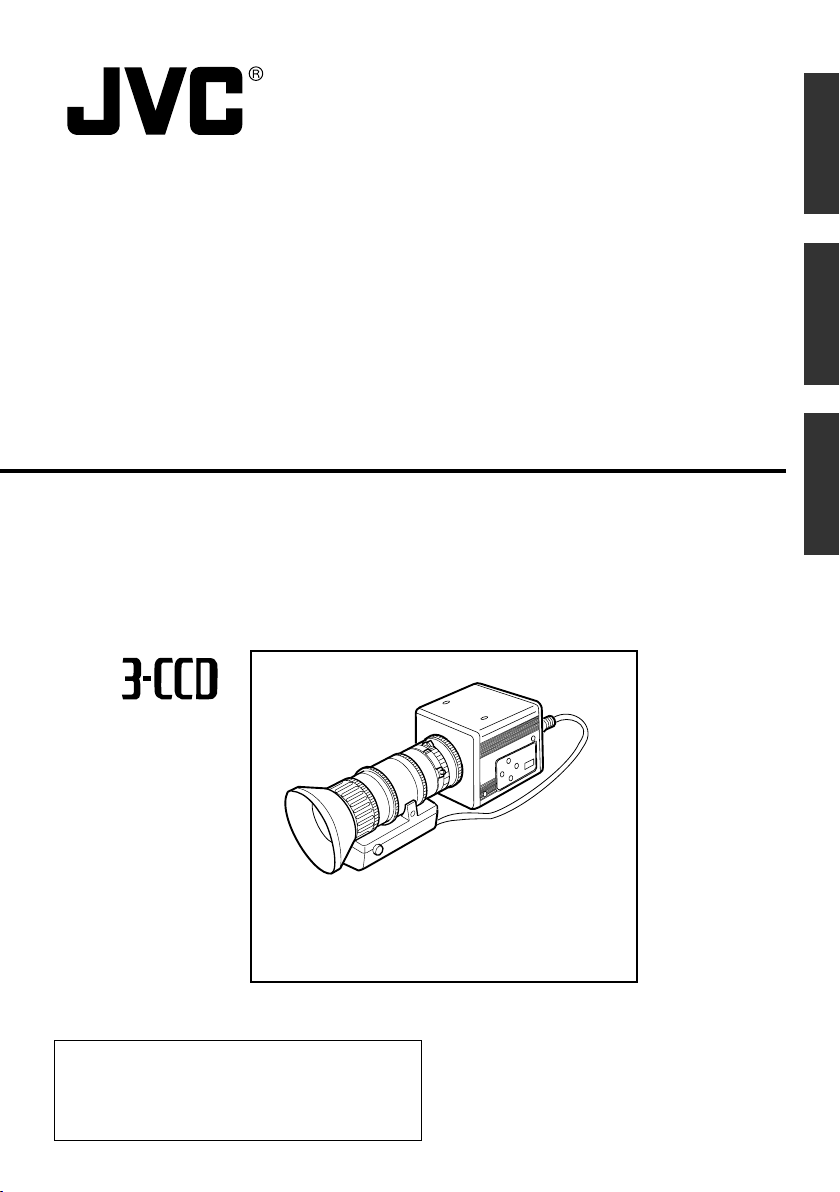
COLOUR VIDEO CAMERA
FARBVIDEOKAMERA
APPAREIL VIDEO EN COULEURS
INSTRUCTION MANUAL
KY-F550
BEDIENUNGSANLEITUNG
EnglishFrançais Deutsch
MODE D’EMPLOI
*Illustration with optional lens attachment.
*Illustration mit montiertem optionalem Objektiv.
*Illustration avec objectif optionnel.
Thank you for purchasing this JVC product.
Before operating this unit, please read the
instructions carefully to ensure the best
possible performance.
This instruction manual is made from 100%
recycled paper.
LWT0159-001B
Page 2
Français
Thank you for purchasing the JVC KY-F550 Colour Video Camera.
WILL RESULT.
LENS
SC45550-011
PROTRUDES MORE THAN
ATTACH A LENS WHICH
NEVER
MAX4mm
4mm SEVERE DAMAGE
WARNING:
BARS
MENU
SET
1
234
AW
80
93,6
0,5
66
67,5
64
These instructions are for KY-F550E.
These instructions are given in three languages: English from page E-2 to E-51
German from page G-2 to G-51
French from page F-2 to F-51
SAFETY PRECAUTIONS
This equipment is in conformity with the provisions and protection requirements of the corresponding European Directives. This equipment is designed for professional video appliances
and can be used in the following environments:
5 Residential (including both of the location type class 1 and 2 found in IEC 1000-2-5)
5 Commercial and light industrial (including, for example, theatres)
5 Urban outdoors (based on the definition of location type class 6 in IEC 1000-2-5)
In order to keep the best performance and furthermore for electromagnetic compatibility we
recommend to use cables not exceeding the following lengths:
Port Cable Length
VIDEO OUT Exclusive Cable 5 meters
RGB,Y/C,SYNC OUT Exclusive Cable 2 meters
LENS Exclusive Cable 0.4 meters
TRIGGER Exclusive Cable 5 meters
REMOTE Exclusive Cable 5 meters
DV Exclusive Cable 4.5 meters
DC IN Exclusive Cable 2 meters
Caution:
5 Where there are strong electromagnetic waves or magnetism, for example near a radio or TV
transmitter, transformer, motor, etc., the picture and sound may be disturbed. In such a case,
please keep the apparatus away from the sources of the disturbance.
WARNING:
TO REDUCE THE RISK OF FIRE OR
ELECTRIC SHOCK, DO NOT EXPOSE
THIS APPLIANCE TO RAIN OR
MOISTURE.
This unit should be used with 12 V DC
only.
CAUTION:
To prevent electric shocks and fire
hazards, do NOT use any other power
source.
Note:
The rating plate (serial number plate) is on the
bottom of the unit.
CAUTION
To prevent electric shock, do not open the
cabinet. No user serviceable parts inside. Refer
servicing to qualified service personnel.
Risk Class : 1
Type : No Applied Parts
Moisture Protection : Ordinary
AP/APG Category : No
Operation Mode : Intermit
E-2
Page 3

SAFETY PRECAUTIONS
JVC Sales Office
1. JVC Professional Europe Ltd.
Ullswater House, Kendal Avenue,
London W3 0XA U.K.
tel: +44(020)8896-6000
2. JVC Professional Europe Ltd. Frankfurt, Germany
Gruener Weg 10, 61169 Friedberg /
Hessen, Germany
tel: +49(06031)6050
3. JVC Professional Europe Ltd. Milano,
Italy
Via Cassanese 224 Palazzo Tiepolo
20090 Segrate-Milano Oltre, Italy
tel: +39(02)380501
4. JVC Professional Europe Ltd. Paris,
France
1 Avenue Eiffel 78422 Carrieres-SurSeine Cedex, France
tel: +33(01)61 04 11 11
5. JVC Professional Europe Ltd.
Barcelona, Spain
Ctra. De Rubi, 88 Ed. Can Castanyer
08190 Sant Cugat del Valles (Barcelona)
Spain
tel: +34(93)565 3220
English
8. JVC Professional Europe Ltd.
Stockholm, Sweden
Veddestavagen 15,S-175 62 Jarfalla,
Stockholm, Sweden
tel: +46(08)7950400
9. JVC Professional Europe Ltd.
Tonsberg, Norway
PO Box 2012PT, Wirgenes v5, Barkaker
N-3103 Tonberg Norway
tel: +47(333)61600
10. JVC Professional Europe Ltd.
Tastrup,Denmark
Helgeshoej Alle 30 DK-2630 Taastrup,
Denmark
tel: +45(43)509000
11. Spitzer Electronics AG
Muehlemattstrasse 13, CH-4104 Oberwill
Switzerland
tel: +41-61-405-1111
12. Oy Hedpro Ab
Lauttasaarentie 50 FIN-00200 Helsinki
Finland
tel: +358-9-6828244
6. JVC Belgium S.A./N.V.
Rue de la Petite Ile 3, Klein-Eilandstraat,
Bruxelles 1070 Brussel, Belgium
tel: +32(02)529-4211
7. JVC Professional Europe Ltd. Leiden,
Nederland
JVC Plein, De Heyderweg 2, 2314 XZ
Leiden, Nederland
tel: +31(071)545-3333
13. ILVI S.A
62,Piraeus Ave., 183 46 Moschato,
Greek
tel: +30-210-4832855
E-3
Page 4

Contents
1. Getting Started
Features ............................................................................................................................................... 6
Points to Note During Use .................................................................................................................... 7
Part Names and Functions ................................................................................................................... 8
Description of Terminals ..................................................................................................................... 12
2. Preparation Before Shooting
Connecting Through Digital Output .................................................................................................... 14
Connecting Through Analogue Output ............................................................................................... 16
Mounting the Lens .............................................................................................................................. 17
Connecting the Power Supply ............................................................................................................ 18
Mounting the Camera ......................................................................................................................... 19
Precautions to Prevent Camera From Falling .................................................................................... 20
3. Setting and Adjustment During Shooting
External Monitor Adjustment .............................................................................................................. 21
White Balance Adjustment ................................................................................................................. 22
White Shading Adjustment ................................................................................................................. 24
4. Various Modes of Shooting
Shooting the Computer Monitor .......................................................................................................... 26
Output of Negative Image ................................................................................................................... 27
White Spot Correction ........................................................................................................................ 28
E-4
Page 5

5. Setting Via the Menu Screen
Flow of Menu Screens ........................................................................................................................ 30
Setting Procedures ............................................................................................................................. 32
“EXPOSURE” Screen ......................................................................................................................... 33
“ADVANCED EXPOSURE” Screen .................................................................................................... 35
“WHITE BALANCE” Screen................................................................................................................ 36
“PROCESS (1/2)” Screen ................................................................................................................... 38
“PROCESS (2/2)” Screen ................................................................................................................... 40
“SYSTEM” Screen .............................................................................................................................. 41
“MATRIX ADJUST” Screen ................................................................................................................ 42
“CAPTURE” Screen ............................................................................................................................ 43
“FILE MANAGE” Screen ..................................................................................................................... 44
6. Others
Connecting the Remote Control Unit .................................................................................................. 46
Connecting the IEEE 1394 Cable ....................................................................................................... 48
Connecting the analogue output (D-SUB) Cable ................................................................................ 48
Technical Information ......................................................................................................................... 49
Specifications ..................................................................................................................................... 50
English
English
Notations and Symbols Used in This Manual
Caution
Note
☞
All product names in this manual are trademarks or registered trademarks of their respective companies.
Marks such as ™, ® and © are not used in this manual.
Precautions during operation are stated.
Restrictions of functions and specifications are stated for reference purposes.
Indicates the page and item to refer to.
E-5
Page 6

1. Getting Started
Features
● High quality images can be obtained through high sensitivity of 2000 lx (F11) and high resolution of
horizontal resolution at 800 lines via the newly developed 12-bit DSP.
● Miniature and Lightweight Camera that Employs C Mount
Employment of C mount and 1/3-inch colour separation optics, and compact design through high-density
mounting of the newly developed IC.
● Equipped with D-SUB terminal
Multiple types of output signals which include RGB, Y/C, composite video and composite sync signal
enable this unit to be connected directly to various types of device.
● Equipped with DV Terminal
Digital video signals can be sent to IEEE 1394 compliant devices.
● EBU-compliant Built-in Colour Bars Generator
Colour monitor can be adjusted with ease with the use of EBU colour bars.
● Variable Scan Shutter
Eliminates flicker when shooting screen pictures other than PAL, such as computer screens.
● Slow shutter
Accumulate up to 200 frames of image (approximately 8 seconds). Boosts the brightness of images during shooting for objects with insufficient illumination and little motion.
● Equipped with White Shading Function
Corrects colour shading triggered by optical characteristics.
● Black Stretch/Black Compress Feature
Stretches or compresses the gain of the dark section in an image to adjust the tone of that section.
● Negative
Used for special purposes such as shooting using films.
● AE (Automatic Exposure)
6 selectable modes in the AE area that are useful when there is a difference in brightness between the
object and its surroundings. In addition, exposure settings can also be performed according to shooting
conditions via selection of AE level adjustment or photometry detection.
● Random Trigger Correction Feature
Fast moving objects can be shot with triggering input timing.
● Freeze Correction Feature
Still images (frozen images) of the camera can be captured with triggering input timing.
● Built-in White Spot Correction Feature
● Equipped with Remote Terminal
Supports remote control via the remote control unit (sold separately).
E-6
Page 7

Points to Note During Use
● For important shootings, perform trials in advance to ensure that they are properly recorded.
● We will not compensate for contents lost due to the malfunction of this unit.
䡵 Characteristic CCD Phenomena
● Smear and Blooming
When shooting a bright light source, the CCD may induce white streaks (smear) in the vertical direction
of the light source. When the light source is extremely bright, light of the surroundings may expand
(blooming).
● Aliasing
Note that a jagged effect may occur when shooting striped patterns or lines.
● White spot
Operating this unit under a high temperature may give rise to white spots in the image. Ensure to use
this unit within the specified range (–5˚C to 40˚C). White spots may also appear when set to slow
shutter.
This unit comes with the white spot correction feature that helps to reduce this phenomenon.
☞ Page 28
䡵 Precautions During Handling
● Strong Electromagnetic Waves or Magnetism
When placed near radios or TV transmitters, or transformers and monitors that emit strong magnetism,
noise or colour change may occur in the image. Ensure that this unit is kept away from the above
during use.
● Compatible Lens ☞ Page 17 ‘Mounting the Lens’
Lens mount of this unit makes use of C mount and there are restrictions on the type of lens to be used.
Pay attention to their performance, dimensions, length of the screw portion when lenses other than
those specified are used.
This unit is not equipped with back focus adjustment function. If zoom len is to be used, please use
only lens which are equipped with back focus function.
● Cleaning the Body of this Unit (Turn off the power before cleaning.)
Wipe using a soft cloth.
Do not wipe with thinner or benzene. These may corrode or tarnish the surface.
When it is extremely dirty, wipe using a neutral detergent diluted with water, follow by wiping with a
dry cloth.
● When not in use, turn off the power of the system to reduce power consumption.
● Do not mount unit at locations that emit radiation, X-rays or corrosive gases.
English
E-7
Page 8
1. Getting Started (continued)
Part Names and Functions
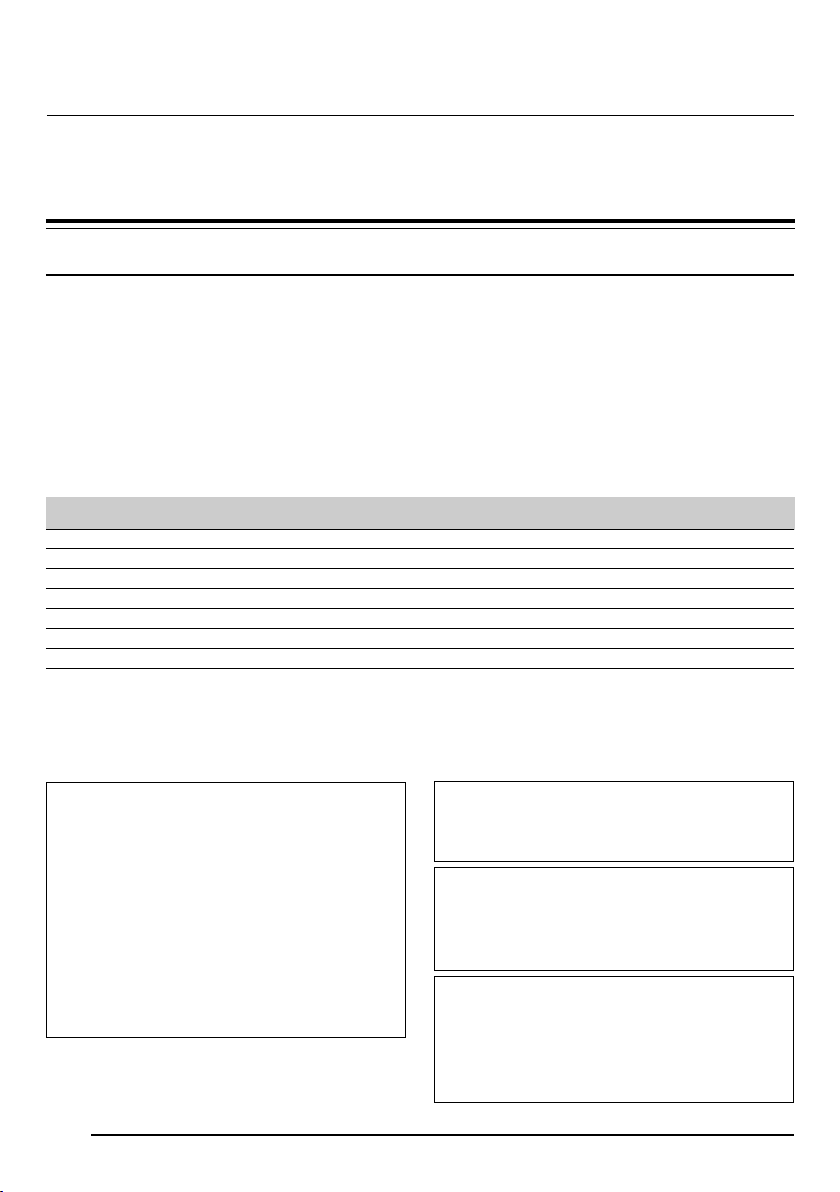
Front / Bottom
1
2
3
4
1 Lens Mount
For mounting lens. Suitable for C mount lens
meant for 3 CCDs.
☞ Page 17 ‘Mounting the Lens’
2 Camera Mounting Bracket
Supplied together with this unit. Mount it to the
top or bottom surface according to the conditions of use. Mount with the fastening screws
for the camera mounting bracket 3.
☞ Page 19 ‘Mounting the Camera’
3 Fastening Screws for Camera
Mounting Bracket
Supplied together with this unit.
(M2.6 x 6 mm, 2 pcs)
Caution
Make sure to use screws that are supplied with
this unit. Use of screws that are 6 mm or longer
in length may give rise to malfunction of the unit.
E-8
4 Camera Mounting Screw Holes (1/
4-20UNC)
Use when mounting this unit to fixer or swivel
bases.
(Use screws that are 7 mm or shorter in length. )
7mm
and
below
Page 9
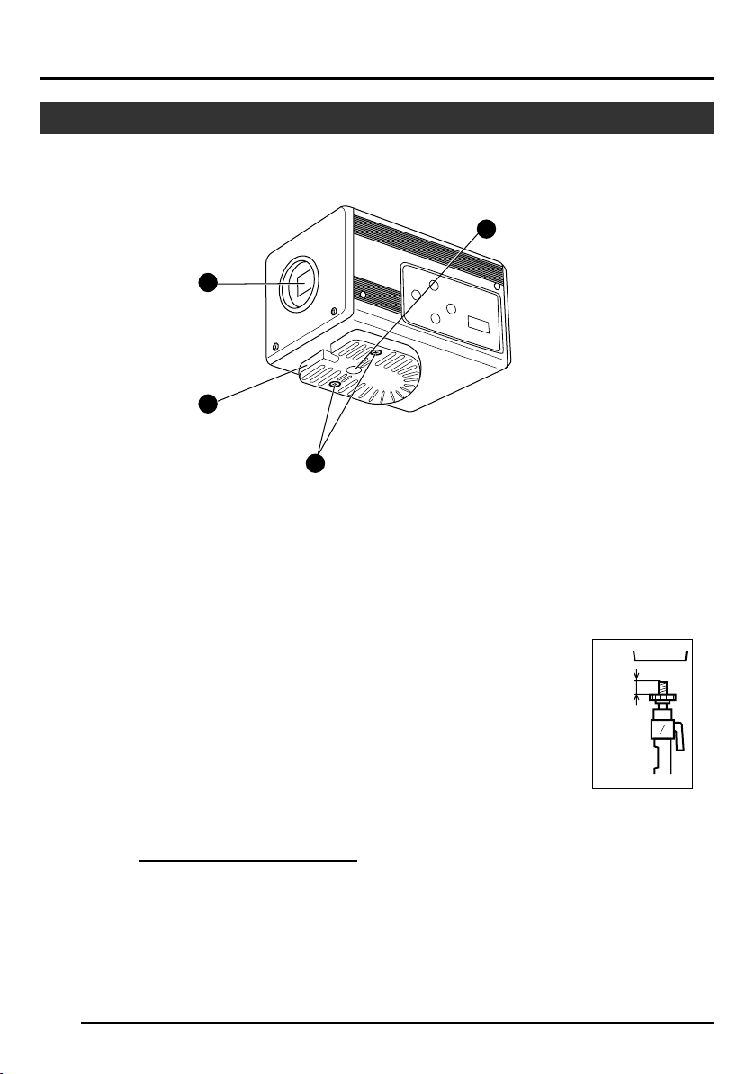
Part Names and Functions (continued)
Side
5 [MENU] Menu Button
Press this button for 1-2 seconds. Menu screen
will be output from the various output terminals.
Press the button for 1-2 seconds again to clear
the menu screen.
☞ Page 32 ‘Setting Procedures’
6 [SET] Set Button
When the menu screen is displayed, use it to
select a submenu or to confirm a selected item
or set value.
☞ Page 32 ‘Setting Procedures’
5 7 6
5 / BARS
1234
SETMENU
∞ / AW
8
7 [5/BARS] Up/Colour Bars Button
8 [∞/AW] Down/Auto White button
䡵 When menu screen is displayed
Press these buttons to move between selection
items on the menu screen.
Use the [5] button to move upwards.
Use the [∞] button to move downwards.
Used for altering the set values when an item
is being selected.
䡵 When the menu screen is off
● Press the [AW] button to adjust the white
balance.
☞ Page 22 ‘White Balance Adjustment’
● Press the [AW] button for 1-2 seconds to
adjust the white shading.
☞ Page 24 ‘White Shading Adjustment’
● Press the [BARS] button to switch between
the colour bars output and camera image
output.
Use this button when adjusting the monitor
or when recording colour bars signal.
☞ Page 21 ‘External Monitor Adjustment’
English
E-9
Page 10
1. Getting Started (continued)
Part Names and Functions (continued)
5 / BARS
1234
SETMENU
∞/ AW
Up:
Down:
ON
OFF
9
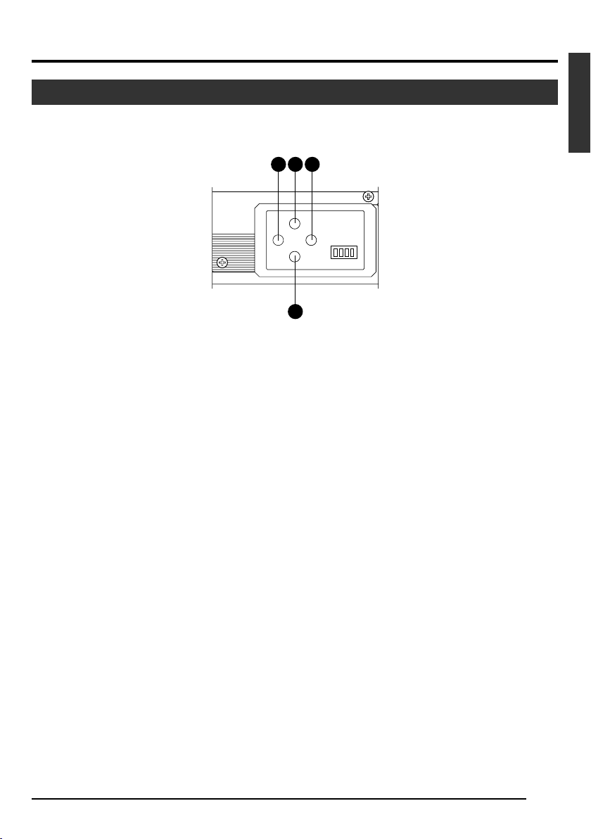
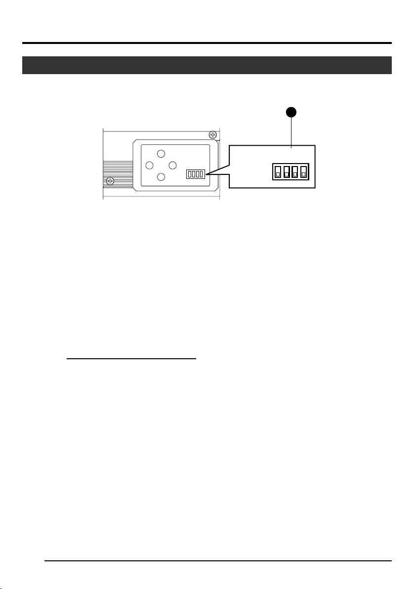
1234
9 Function Setting Switch
Use for setting the functions of this unit.
Select the switches when the unit is at power
off condition.
● Switch 1 <DV OUTPUT>
[ON] : Compressed DV signal (IEEE1394)
of the camera images will be output.
[OFF] : DV signal will not be output.
Note
If [ON] is selected, the analogue output will
exhibit the same level of horizontal resolution
(about 540 lines) as the DV output.
● Switch 2 <DSUB OUTPUT>
[ON] : Y/C signal will be output.
[OFF] : RGB signal will be output.
● Switch 3 <SYNC ON GREEN>
[ON] : Sync signal will be superimposed
onto the Green (G) channel of the
video signal output to the [RGB, Y/
C, SYNC OUT] terminal 0.
[OFF] : Sync signal will not be superim-
posed.
● Switch 4 <CONTROL MODE>
[ON] : Operate the camera via [DV] termi-
nal (IEEE1394).
Operation via [MENU], [SET], [5/
BARS], [∞/AW] buttons and the remote control unit will not function.
[OFF] : Operate the camera via the buttons
on this unit or the remote control
unit. Operation via [DV] terminal
(IEEE1394) is not functional.
E-10
Page 11
Part Names and Functions (continued)
Back
11
10
REMORT
DV
12
POWER
13
DC IN
17
RGB,
TRGGER
Y/C,
SYNC OUT
LENS
SEE INSTRUCTION MANUAL
VIDEO OUT
141516
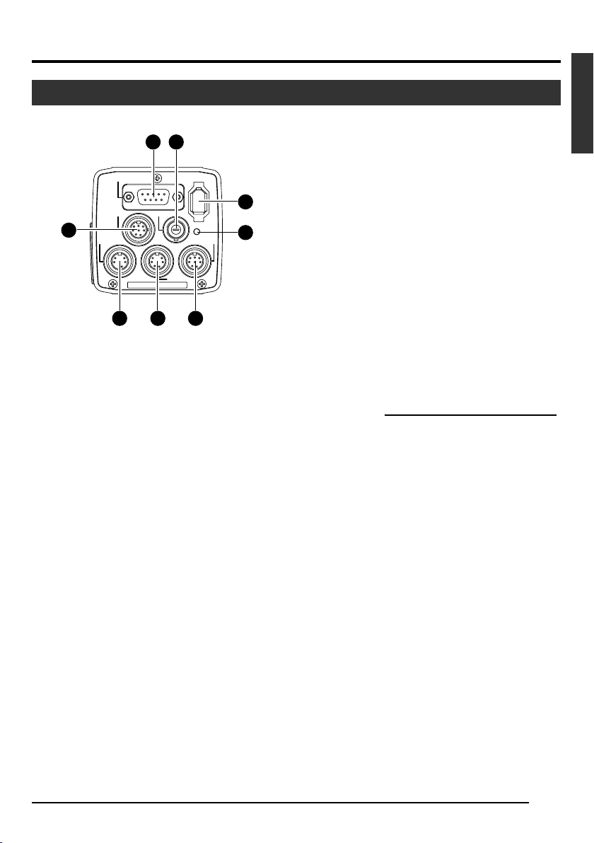
0
[RGB, Y/C, SYNC OUT] Analogue
Output Terminal
Output terminal for R/G/B, Y/C and composite
video/sync signal.
☞ Page 10 ‘9 Function Setting Switch’
☞ Page 13 ‘Description of Terminals’
☞ Page 48 ‘Connecting the analogue output (D-
SUB) Cable’
! [VIDEO OUT] Video Signal Output
Terminal
Output terminal for composite video signals.
Connect to video input terminals such as monitors or switchers.
@ [DV] Digital Output Terminal
Digital output terminal for video. Connect this
terminal to computer’s [IEEE 1394] terminal or
[DV] terminal equipped video devices.
● If this terminal is to be used, set Switch 1 located at the side of this unit to [ON].
● If this terminal is to be used to operate the
camera, set Switch 4 located at the side of
this unit to [ON].
☞ Page 10 ‘9 Function Setting Switch’
☞ Page 13 ‘Description of Terminals’
☞ Page 48 ‘Connecting the IEEE 1394 Cable’
# [POWER] Power Indicator Light
Lights up when power is supplied to this unit.
$ [DC IN] Power Input Terminal
(Mini DIN 8 Pin, Female)
Power of this unit (DC 12 V) is supplied through
this terminal.
Use an AC adaptor (AA-P700) for the power
supply.
☞ Page 12 ‘Description of Terminals’
☞ Page 18 ‘Connecting the Power Supply’
% [REMOTE] Remote Terminal
(Mini DIN 6 Pin, Female)
Terminal for connection to remote control unit
(RM-LP55 or RM-LP57, both sold separately).
☞ Page 12 ‘Description of Terminals’
☞ Page 46 ‘Connecting the Remote Control Unit’
Caution
When using this unit as medical equipment, the
remote control unit (RM-LP55 or RM-LP57 sold
separately) cannot be used.
^ [TRIGGER] Trigger Terminal
(Mini DIN 5 Pin, Female)
For inputting and outputting the various types of
timing signal when Slow Shutter or Random Trigger function is used.
☞ Page 12 ‘Description of Terminals’
☞ Page 49 ‘Technical Information’
& [LENS] Lens Connection Terminal
(Mini DIN 8 Pin, Female)
Connect the lens cable.
☞ Page 12 ‘Description of Terminals’
☞ Page 17 ‘Mounting the Lens’
E-11
English
Page 12
1. Getting Started (continued)
Description of Terminals
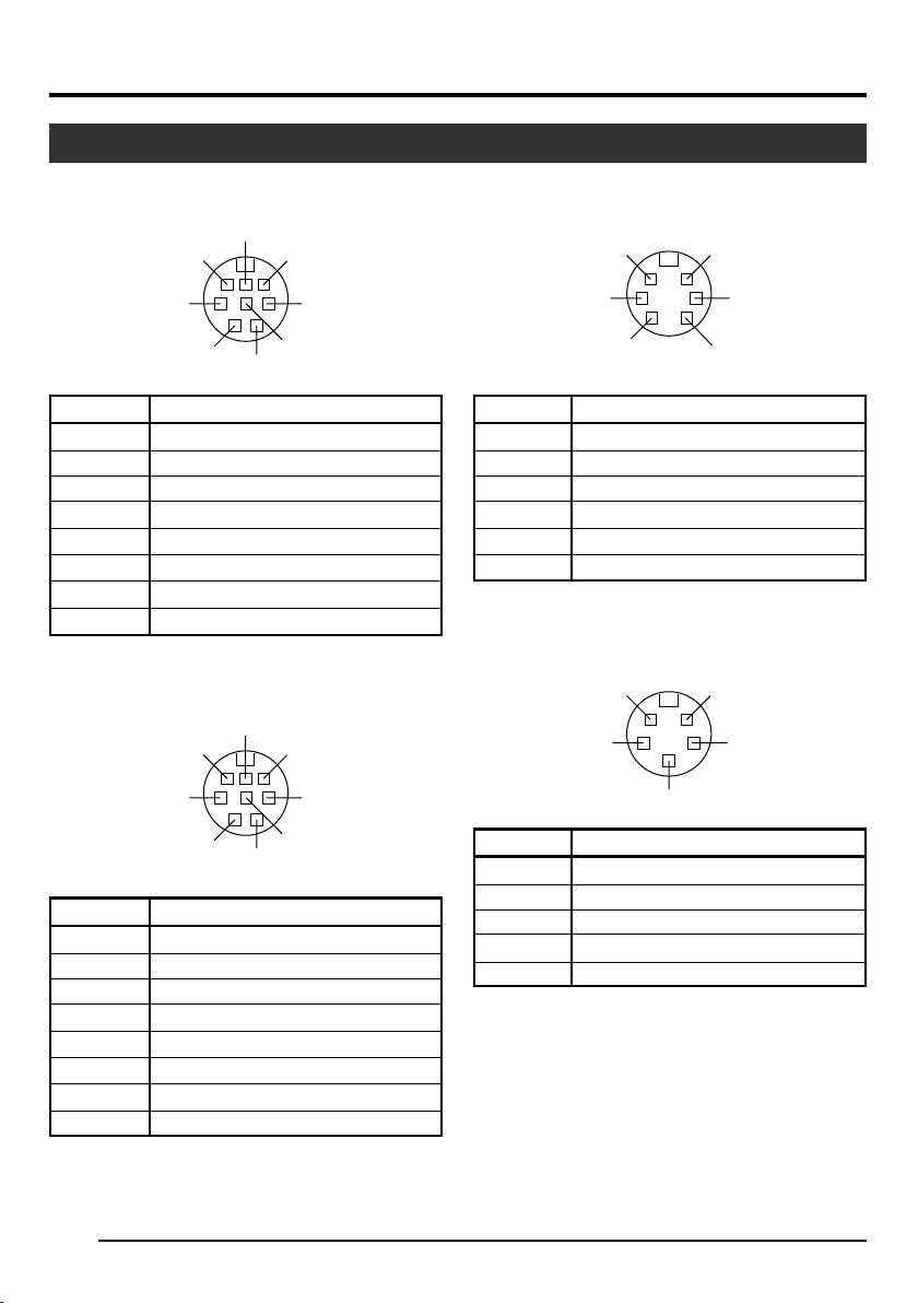
Power Input Terminal (Mini DIN 8 Pin,
Female)
Pin No.
1
2
3
4
5
6
7
8
NC
GND
NC
NC
GND
+ 12 V Input
NC
+ 12 V Input
7
8
5
2
6
3
4
1
Signal
Lens Connection Terminal (Mini DIN 8
Pin, Female)
Pin No.
1
2
3
4
5
6
7
8
LENS TYPE
GND
IRIS CONTROL
+ 12 V Output
SERVO SEL
ZOOM CONTROL
FOCUS CONTROL
Y SIGNAL OUT
7
8
5
2
6
3
4
1
Signal
Remote Terminal (Mini DIN 6 Pin, Female)
Pin No.
1
2
3
4
5
6
6
4
2
GND
OPERATE(L:ON)
GND
SID2(TX)
SID1(RX)
+ 9 V Output
5
3
1
Signal
Trigger Terminal (Mini DIN 5 Pin, Female)
(TCS7858 : Hoshiden)
5
3
Pin No.
1
2
3
4
5
Notes
● Please consult your JVC-authorized dealer on
connection of trigger terminal.
● Ensure to use cables that are shielded.
Suitable Plug: Mini DIN 5 PIN
SI Output
TRIG Input
GND
WEN Output
NC
4
2
1
Signal
E-12
Page 13
Description of Terminals (continued)
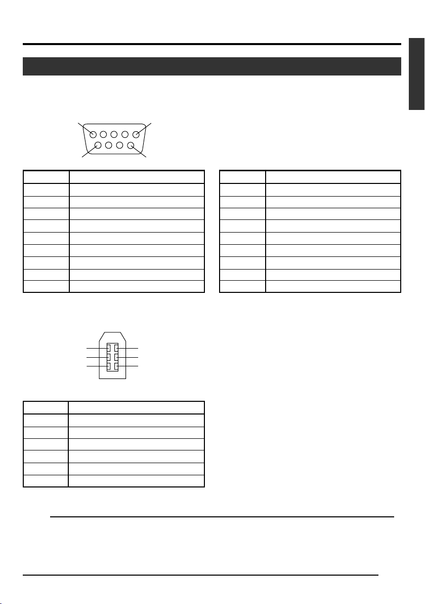
Analogue Output Terminal (D-sub 9
PIN, Female)
Pin No.
1
2
3
4
5
6
7
8
9
5
9
RGB Output
GND
GND
R OUT
G OUT
B OUT
Composite video OUT
Composite sync OUT
GND
GND
1
6
Digital Output Terminal
6
4
2
5
3
1
Notes
● Cannot be connected to computer monitor.
● Use the function setting switches located at the
side of this unit to select between RGB or Y/C
output.
Pin No.
1
2
3
4
5
6
7
8
9
GND
GND
Y OUT
C OUT
Composite video OUT
Composite Sync OUT
GND
GND
Y/C Output
English
Pin No.
1
2
3
4
5
6
VP (POWER)
VG (GND)
TPB TPB +
TPA TPA +
Signal
Note
Ensure to attach the supplied clamp filters to the cables connected to the Analogue Signal Output [RGB, Y/
C, SYNC OUT] terminal and Digital Output [DV] terminal in order to reduce unwanted electromagnetic
emissions. ☞ Page 48
E-13
Page 14
2. Preparation Before Shooting
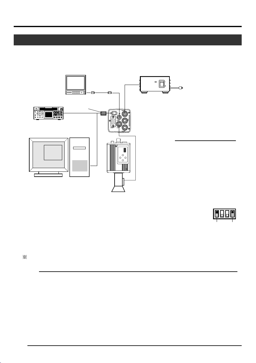
Connecting Through Digital Output
Computer can be used to control this unit remotely, record captured images on digital device or display them
on the computer or monitor. (Please pre-install the exclusive software for this unit.)
BR-DV3000
BR-DV6000
DV VTR
Exclusive Software
Computer
Monitor
Clamp filter
(accessories)
‘Connecting the
IEEE 1394 Cable’
(Page 48)
IEEE 1394
Terminal
‘Mounting the
Lens’ (Page 17)
BNC CABLE
[VIDEO OUT]
[DV]
‘Connecting the
Power Supply’
(Page 18)
DC IN
POWER
DV
VIDEO OUT
OUT
SYNC
,
Y/C
,
LENS
RGB
TRGGER
1234
SETMENU
5 / BARS
[DC IN]
REMORT
5/ AW
AA-P700
AC ADAPTER AA-P700
POWER
ON
AC IN
OFF
AC Adapter
SEE INSTRUCTION MANUAL
Notes
[LENS]
● 2 or more of this unit cannot be connected to 1 computer.
● Ensure to attach the supplied clamp
filter to the cable connected to the Digital Output [DV] terminal in order to reduce unwanted electromagnetic emissions.
1.
Connect the [DV] terminal of this unit to the computer’s DV [IEEE1394] terminal.
2.
Set the Switch 1 and Switch 4 located at the side of this unit to [ON] (upper side).
3.
Switch on the power of this unit.
4.
Set the “DV SYSTEM” under “SYSTEM” screen to “JVC”.
5.
Power on the computer and launch the software.
1234
ON
OFF
Switch 1 Switch 4
With the exclusive software provided, it is possible to select the various camera settings and operate the
camera for shooting. For details, please consult your JVC-authorized dealer.
Please refer to the software’s HELP menu for details on how it could be used.
Caution
● Perform this when the devices are off.
● When the software has been launched, do not switch on/off the power of the AC adapter or insert and
remove the IEEE 1394 cable.
● Disable the automatic standby or hibernation function of your computer before using it.
● This unit’s power can be supplied from the IEEE 1394 cable. However, use the power supply voltage
between 10.5 V - 15 V if power lens is to be used. Ensure that the supply capacity of the supply source is
adequate in meeting the total power consumptions of both this unit and the power lens used.
E-14
Page 15

Connecting Through Digital Output (continued)
䡵 Specification of Compatible Computer
● Pentium 4 2.4 GHz or higher DOS/V, PC/AT compatible machine is recommended.
● More than 256 MB RAM is recommended.
● Hard disk with a minimum 20 MB of available space.
● When video recording is performed, 7200 rpm and above IDE disk (RAID system is recommended).
● OS : Windows 2000Pro/XP
● Video card : AGP graphic card incorporated with NVIDIA GeForce4MX or GeForceFX chip (GeForce
4MX420, GeForce FX5700)
● DirectX 9.0 or later versions of Enduser Runtime
䡵 Suitable IEEE Host Adapter
● IEEE1394 host adapter card : Matrox Meteor 2-1394, Ratoc REX-CFW3
䡵 Compatible Lens
● Fujinon T14 X 5.5MD
䡵 Option
● AC Adapter : AA-P700
(Using the exclusive software with other graphic cards and under PC environment other than abovementioned might cause a drop in the display performance of the preview window or error might occur.)
For latest information, please check the following homepage.
http: //www.jvc-victor.co.jp/english/pro/prodv/download/index.html
For details, please consult your JVC-authorized dealer.
English
E-15
Page 16
2. Preparation Before Shooting (continued)
AC ADAPTER AA-P700
POWER
ALARM
SHEET
PAPER
DATA
OPEN
CP700DSA
MITSUBISHI
SETMENU
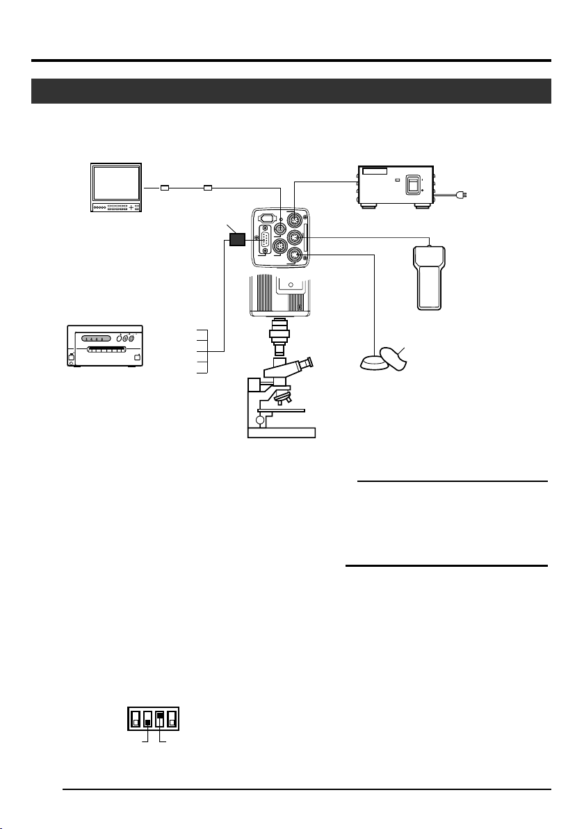
Connecting Through Analogue Output
Images taken by this unit can be output to monitor, colour video printer or other devices.
Monitor
[RGB, Y/C, SYNC OUT]
BNC CABLE
Clamp filter
(accessories)
[VIDEO OUT]
DV
OUT
SYNC
,
Y/C
,
RGB
VIDEO OUT
LENS
DC IN
POWER
TRGGER
‘Connecting the
Power Supply’
(Page 18)
[DC IN]
REMORT
[REMOTE]
SEE INSTRUCTION MANUAL
[TRIGGER]
AA-P700
AC ADAPTER AA-P700
POWER
ON
OFF
AC Adapter
AC IN
VC-451-2
CP700DSA
MITSUBISHI
]
ONLINECOPY & CUTPAPER FEED
PAPER
ALARM
SHEET
DATA
POWER
OPEN
Colour Video Printer etc.
1.
Connect device such as the Colour Video Printer
G/Y
B/C
SYNC
VBS
R
to this unit’s [RGB, Y/C, SYNC OUT] terminal.
2.
Set the switches located at the side of this unit.
● Setting Switch 2
Microscope
Adapter
Trigger Switch
Caution
● Perform this when the devices are off.
● Use the 1/3-inch, C mount adapter for the micro-
scope adapter.
REMOTE
CONTROL
UNIT
RM-LP55
RM-LP57
Set this switch to [ON] (upper side) for Y/C
output.
Set this switch to [OFF] (lower side) for RGB
output.
● Setting Switch 3
Set this switch to [ON] (upper side) if sync signal is to be superimposed onto the Green (G)
channel of the video signal.
☞ Page 10 ‘9 Function Setting Switch’
Example: During RGB output
1234
3.
Switch on the power of this unit.
ON
OFF
Switch 3Switch 2
Notes
● Connect a switch between PIN 2 (TRIG) and PIN
3 (GND) of the [TRIGGER] terminal. If this switch
is set to [ON], a trigger will freeze the input image
to the camera and capturing of images synchronized with the trigger is possible.
● Ensure to attach the supplied clamp filter to the
cable connected to the Analog Signal Output
[RGB, Y/C, SYNC OUT] terminal in order to reduce unwanted electromagnetic emissions.
☞ Page 48
E-16
Page 17

Mounting the Lens
Follow the procedures below when mounting the auto iris lens.
Refer to the ‘instruction manual’ for the lens as well.
1.
Align and press the threaded portion of the lens
mount against the threaded portion of this unit’s
lens mount and turn the mount fastening ring
clockwise slowly until the lens is firmly attached
to this unit.
Mount Fastening Ring
Camera Head
Threaded
Portion
2.
(Male)
Lock
Note
Lens
1.
Compatible Zoom Lens
T14 x 5.5MD
Caution
● Perform this when the unit is off. Connecting with
the power on may give rise to malfunction of the
unit.
● When removing the lens mount cap, ensure that
no foreign substances are inside the mount.
● Lenses are not supplied with this unit. Depending
on the lens being used, this unit may be damaged.
As such, ensure to use lens that are 4 mm or below, reference from the lens mount.
4 mm and below
To change the position of the lens rotation,
1 First, loosen the mount fastening ring by rotat-
ing it anti-clockwise by 1/4 turn as viewed from
the lens side.
2 Turn the lens gently, adjust the position and
tighten the mount fastening ring again.
2.
Plug the lens cable into the [LENS] terminal at
the back of the unit and ensure that it is locked.
Iris control is carried out from this unit.
䡵
Setting the “IRIS MODE” of the “EXPOSURE”
Screen
☞ Page 33
● If auto iris lens is to be used and iris control is to
be automatically carried out, set to “AUTO”.
● If auto iris lens is to be used and iris control is to
be fine-tuned, set to “MANUAL”.
English
E-17
Page 18

2. Preparation Before Shooting (continued)
Connecting the Power Supply
Connect the [DC IN] terminal at the back of this unit to the [TO CAMERA] terminal of the AC adaptor (AAP700) using the power cable supplied (2 m).
VIDEO OUT
REMORT
DV
POWER
DC IN
[DC IN]
Terminal
AC IN
AA-P700
AC 230 V
White Marking
Connect the end with
white marking to the
AC adaptor.
AC Adapter
DC 12V=OUTPUT
TO CAMERAS(Y/C) OUTPUT
EITHER
OUTPUT
MAX 1.25A
POW
ER
DC IN
VIDEO OUTPUT
SEE INSTRUCTION
MANUAL
[TO CAMERA] Terminal
Power Cable (2 m)
(accessories)
● Insert plug fully, turn ring and ensure
RGB,
TRGGER
Y/C,
SYNC OUT
LENS
SEE INSTRUCTION MANUAL
that it is fastened.
Ring
Plug
Notes
● Ensure to make use of AA-P700 for the power supply.
When connecting, ensure that power switch of AA-P700 is turned OFF.
Connecting with the power on may give rise to malfunction of the equipment.
● When power is supplied, it takes several seconds before this unit is operable.
When the “SHUTTER” item under “EXPOSURE” screen is set to “SLOW”, it might take even longer time.
● Allow a 10 second interval after switching off the power before turning on again. If the power switch is
turned ON and OFF too soon, malfunctioning such as startup failure may occur.
Caution
In case of medical use
Make sure to use the specified AC Adapter.
UK Market ................................... AA-P700EK
Other European Market ............. AA-P700EG
E-18
Page 19

Mounting the Camera
<Procedures for mounting camera mounting bracket>
Use the supplied camera mounting bracket and 2
fastening screws of the camera mounting bracket to
mount it to the top or bottom surface.
Caution
Make sure to use screws that are supplied with this
unit. Use of screws that are 6 mm or longer in length
may give rise to malfunction of the unit.
<Mounting Procedures>
English
Anti-rotation Hole
Camera Mounting Bracket
Screw Hole for Mounting Camera
● To mount this unit, make use of the screw holes
for mounting the camera on the camera mounting
bracket.
● When mounting this unit, make use of the antirotation hole to prevent it from falling.
E-19
Page 20

2. Preparation Before Shooting (continued)
Precautions to Prevent Camera From Falling
Safety cable to Prevent
Falling of Equipment
4 mm
1-1.5 mm
Camera Head
Caution
E-20
● Special attention is required when mounting to the wall or ceiling. Get a contractor
to perform the work and avoid doing it on your own. Unit may fall off and cause
injuries or accidents.
● Mount the unit to a secure place using safety cable to prevent it from falling. To
mount, make use of the bracket fastening screw holes on the face without the camera mounting bracket. (M2.6 x 4 mm) Pay attention also to the length of the cable.
● Strength of cable to prevent falling of unit shall be at least 10 times greater than the
total mass of the camera and lens.
Page 21

3. Setting and Adjustment During Shooting
External Monitor Adjustment
Display the built-in colour bars signal at the camera on the monitor to perform colour/contrast/brightness
adjustment.
1.
2.
[BARS]
Connect the colour video monitor to the [VIDEO OUT] of this
unit.
Make sure that the Switch 4 located at the side of this unit is
RGB,
LENS
TRGGER
5 / BARS
SETMENU
∞/ AW
Y/C,
SYNC OUT
SEE INSTRUCTION MANUAL
1234
Switch 4: [OFF]
DV
VIDEO OUT
POWER
DC IN
REMORT
1.
set to [OFF] (lower side).
2.
Press the [BARS] button to output the colour bars signal (EBUcompliant colour bars).
3.
With the colour bars displayed, turn [BLUE CHECK] at the
monitor to ON. Screen turns into a monochrome of blue and
colour bars appear as blue stripes.
4.
Turn the [CHROMA] adjustment knob on the monitor and
adjust colour bars 1 and 7 to the same brightness level.
5.
With [BLUE CHECK] in the ON mode, turn the [PHASE] adjustment knob on the monitor to adjust colour bars 3 and 5
to the same brightness level.
6.
If brightness of colour bars 1 and 7 vary upon [PHASE] adjustment, repeat chroma adjustment as in step 4..
7.
Turn [BLUE CHECK] at the monitor to OFF and return to the
normal screen (R. G. B are all displayed).
English
3.~7.
White
Yellow
Cyan
Green
Magenta
Red
Blue
Black
12345678
E-21
Page 22

3. Setting and Adjustment During Shooting (continued)
White Balance Adjustment
Colour of light (colour temperature) may vary with light sources. When light source for illumination of object
is changed, adjust white balance (AUTO WHITE) again. Do not place strong reflectors such as metals near
the object. This may cause error in achieving white balance.
[MENU] [SET]
[5]
5 / BARS
SETMENU
∞/ AW
[∞]
Switch 4: [OFF]
1234
Set ValueItem
-- ---CE-WHI TE BALAN
WH I T E
LEVEL(R)
LEVEL(B)
SHADING
LEVEL(R)
LEVEL(G )
LEVEL(B)
PAGE BACK
CEBALAN
AUTO1
0
0
TPRESE
- - - - - -
- - - - - -
- - - - - -
“WHITE BALANCE” Screen
Auto White Operation Area
WHIAUTO E1T
RATOPE ION
Auto White Operation Activated
WHAUTO TIE1
OK (3200K)
White balance adjustment includes Auto White, Full-time Auto White
(FAW), manual and preset.
䡵
Setting procedures for Auto White (“AUTO1”,
“AUTO2”)
Make sure that the Switch 4 located at the side of this unit is set to
[OFF] (lower side).
1.
Press the [MENU] button for 1-2 seconds.
The “MENU” screen will be displayed.
2.
Use the [5/∞] buttons to select “WHITE BALANCE..”, then press
the [SET] button.
The “WHITE BALANCE” screen will be displayed.
3.
Use the [5/∞] buttons to select “WHITE BALANCE”, then press
the [SET] button.
The set value displayed will start to blink.
4.
Use the [5/∞] buttons to select “AUTO1” or “AUTO2”, then press
the [SET] button.
5.
Press the [MENU] button for 1-2 seconds.
The normal screen will be displayed.
Note
Upon returning to the normal screen, place a white object with the
same illumination conditions as the object, zoom in to the white
portion at the centre of the screen (above 80% within the area).
6.
Press the [AW](Auto White) button.
● When auto white is activated, the auto white operation area
and “AUTO WHITE1,2 OPERATION” are displayed on the monitor.
● When white balance is achieved, a rough colour temperature
as well as “AUTO WHITE1,2 OK” will be displayed for about 3
seconds before returning to the normal screen.
Auto White Operation Ends
E-22
Page 23

White Balance Adjustment (continued)
O WH AUT ITE
1
G:OBNJ E CT
Object Error
O WH AUT ITE
1
R:LOERRO W L I T GH
Insufficient Illumination
O WH AUT ITE
1
R:OVERROE R L HT IG
Excessive Illumination
Error Display
When auto white adjustment is not correctly ended, the following
message will be displayed for about 3 seconds.
● “NG : OBJECT” (Object Error)
Displayed when there is little white colour in the object or when
colour temperature is not appropriate.
Change to a white object and perform procedures again to
achieve white balance.
● “ERROR : LOW LIGHT” (Insufficient Illumination)
Displayed when the illumination is too dark. Open the lens aperture or brighten the illumination and perform procedures again
to achieve white balance.
● “ERROR : OVER LIGHT” (Excessive Illumination)
Displayed when the illumination is too bright. Close the lens
aperture or darken the illumination and perform procedures
again to achieve white balance.
Caution
● When this unit is set as below, auto white cannot be activated.
• When the “SHUTTER” item under “EXPOSURE” screen is
set to “SLOW”.
• When the “MODE” item under “CAPTURE” screen is set to
“RANDOM TRG”.
• When auto white shading is being activated.
● If white balance is to be adjusted when processing frozen im-
age, return to the normal screen before activating auto white.
English
䡵 Full-time Auto White (FAW) Function
Automatic adjustment of white balance according to different illumination conditions.
This mode is useful when there is no time to readjust white balance or when camera is frequently moved
to locations with different illumination conditions.
● However, white balance cannot be properly achieved in cases that are beyond the adjustable range
of the full-time auto white function, such as when there is only one colour or little white colour in the
object.
● Precision of FAW deteriorates when compared with auto white balance.
● When power is turned on in the FAW mode, it takes about 10 seconds for the FAW automatic adjust-
ment to end.
E-23
Page 24

3. Setting and Adjustment During Shooting (continued)
White Shading Adjustment
There are cases when white balance is achieved for the centre of the screen but not for the upper and lower
ends, hence causing other colours to appear with green or magenta. This is brought about by the lens
characteristics. The process of rectifying this is known as white shading.
[MENU] [SET]
[5]
5 / BARS
SETMENU
∞/ AW
[∞]
Switch 4: [OFF]
1234
1.
--- MENU ---
EXPOSURE . .
WH I T E B ALANCE . .
PROCE SS . .
SYSTEM. .
CAPTURE . .
FILE M
EX I T
ANAGE
..
“MENU” Screen
2.
-- ---CE-WHI TE BALAN
WH I T E
LEVEL(R)
LEVEL(B)
SHADING
LEVEL(R)
LEVEL(G )
LEVEL(B)
CEBALAN
0
0
- - - - - -
- - - - - -
BACKPAGE
- - - - - -
Perform the following setting upon adjusting white balance.
☞ Page 22
䡵 Auto White Shading Adjustment
Make sure that the Switch 4 located at the side of this unit is set to
[OFF] (lower side).
1.
Press the [MENU] button for 1-2 seconds.
The “MENU” screen will be displayed.
2.
Use the [5/∞] buttons to select “WHITE BALANCE..”, then press
the [SET] button.
The “WHITE BALANCE” screen will be displayed.
3.
Use the [5/∞] buttons to select “SHADING”, then press the [SET]
button.
The set value starts blinking and adjustment is possible.
4.
Use the [5/∞] buttons to set value to “AUTO”, then press the
[SET] button.
5.
Press the [MENU] button for 1-2 seconds.
The normal screen will be displayed.
Note
LMANUA
TPRESE
After returning to normal screen, shoot a white object to the entire
screen.
In addition, pay attention to the followings for proper adjustment.
● Use an object which is evenly white.
● Adjust so that the object has an even brightness.
● Set the lens aperture from F4.
“WHITE BALANCE” Screen
3. 4.
-- ---CE-WHI TE BALAN
WH I T E
LEVEL(R)
LEVEL(B)
SHADING
LEVEL(R)
LEVEL(G )
LEVEL(B)
BACKPAGE
Blinking
CEBALAN
0
0
AUTO
- - - - - -
- - - - - -
- - - - - -
E-24
LMANUA
Page 25

White Shading Adjustment (continued)
O SHADING AUT
OPERATION
O SHADING AUT
OK
O SHADING AUT
G:OBNJ E CT
Object Error
O SHADINGAUT
R:LOERRO W L I TGH
Insufficient Illumination
O SHADINGAUT
R: OVERERRO L H TIG
6.
Press the [AW] (Auto White) button for 1-2 seconds.
● When auto shading is activated, “AUTO SHADING
OPERATION” is displayed on the monitor.
● When auto shading adjustment is achieved, “AUTO
SHADING OK” will be displayed for about 3 seconds before
returning to the normal screen.
Caution
● When this unit is set as below, auto white shading cannot be
activated.
• When the “SHUTTER” item under “EXPOSURE” screen is
set to “SLOW”.
• When the “MODE” item under “CAPTURE” screen is set to
“RANDOM TRG”.
• When auto white is being activated.
● If white shading is to be adjusted when processing frozen im-
age, return to the normal screen before activating auto white
shading.
7.
Upon completing auto white shading adjustment, perform
white balance adjustment again.
☞ Page 22 ‘White Balance Adjustment’
Error Display
When auto white shading adjustment is not correctly ended, the
following message will be displayed for about 3 seconds.
● “NG : OBJECT” (Object Error)
Displayed when the object is not evenly white.
Change to an evenly white object and perform procedures again
to achieve auto white shading.
● “ERROR : LOW LIGHT” (Insufficient Illumination)
Displayed when the illumination is too dark. Open the lens aperture or brighten the illumination and perform the procedures
again to achieve auto white shading.
● “ERROR : OVER LIGHT” (Excessive Illumination)
Displayed when the illumination is too bright. Close the lens
aperture or darken the illumination and perform the procedures
again to achieve auto white shading.
English
Excessive Illumination
E-25
Page 26

4. Various Modes of Shooting
Shooting the Computer Monitor
When shooting images of computer monitors or displays, horizontal bands will appear on the screen. To
eliminate the bands, it will be necessary to align the shutter speed with the scanning frequency of the
monitor.
Make sure that the Switch 4 located at the side of this unit is
set to [OFF] (lower side).
1.
Press the [MENU] button for 1-2 seconds.
The “MENU” screen will be displayed.
2.
Use the [5/∞] buttons to select “EXPOSURE..”, then press
the [SET] button.
3.
Use the [5/∞] buttons to select “SHUTTER”, then press the
[SET] button.
The set value starts blinking and adjustment is possible.
4.
Use the [5/∞] buttons to set value to “V. SCAN”, then press
the [SET] button.
5.
Use the [5/∞] buttons to select “LEVEL”, then press the [SET]
button.
6.
Use the [5/∞] buttons to adjust the shutter speed. Pay attention to the screen,
If black bands are visible : use the [∞] button to lower the
shutter speed
If white bands are visible : use the [5] button to increase the
shutter speed
7.
When bands are decreased to the minimum, press the [SET]
button. This will be recorded in the memory of the unit.
8.
Press the [MENU] button for 1-2 seconds.
The normal screen will be displayed.
Computer Monitor
3. 4.
--- ---EXPOSURE
IRIS MODE AU
MA LAUN
LEVEL
GA I N
ELEV L
SHUTT ER
LEVEL
EXPOSURE
ADVANCED
BACKPAGE
“EXPOSURE” Screen
5. 6.
--- ---EXPOSURE
IRIS MODE AU
MA LAUN
LEVEL
GA I N
ELEV L
SHUTT ER
LEVEL
EXPOSURE
ADVANCED
BACKPAGE
- - - - - -
STEP
STEP
NO LAMR
..
- - - - - -
STEP
V. SCAN
1/
..
Band
TO
0dB
TO
0dB
50s
Note
Vertical scanning frequency may vary with computer types and there are cases when bands may not be fully
eliminated. In addition, frequency may also differ depending on the software used.
E-26
Page 27

Output of Negative Image
It is possible to convert video signals from the various output terminals of this unit into negative images.
[MENU] [SET]
[5]
Make sure that the Switch 4 located at the side of this unit is
set to [OFF] (lower side).
1.
5 / BARS
SETMENU
∞/ AW
[∞]
Switch 4: [OFF]
1234
Press the [MENU] button for 1-2 seconds.
The “MENU” screen will be displayed.
2.
Use the [5/∞] buttons to select “SYSTEM..”, then press the
[SET] button.
The “SYSTEM” screen will be displayed.
3.
Use the [5/∞] buttons to select “NEGATIVE”, then press the
[SET] button.
2. 3.
--- ---SYSTEM
NEGA OFFTIVE
XEL COM
DV SYSTEM JVC
PAGE
PENIP
BACK
Blinking
CANCEL
The set value starts blinking and adjustment is possible.
4.
Use the [5/∞] buttons to set value to “ON”, then press the
[SET] button.
This will be recorded in the memory of this unit.
Output image will be converted to negative images.
5.
Press the [MENU] button for 1-2 seconds.
The normal screen will be displayed.
“SYSTEM” Screen
4. 5.
--- ---SYSTEM
NEGA ONTIVE
DV SYSTEM JVC
PAGE
BACK
CANCEL
PENIPXEL COM
English
“SYSTEM” Screen
E-27
Page 28

4. Various Modes of Shooting (continued)
White Spot Correction
As a peculiar common characteristic of CCD, white spots may appear on the screen when it is operated
under high temperature or when shutter speed is prolonged during use.
This unit comes with a white spot correction feature to reduce this phenomenon.
How To Use
䡵 Detection of White Spots
The quantity and size of white spots differ with the temperature and shutter speed during use. Before
using the white spot correction feature, it will thus be necessary to detect the position of the white spots
under the conditions of use.
[MENU] [SET]
[5]
5 / BARS
SETMENU
∞/ AW
[∞]
Switch 4: [OFF]
1234
2. 3.
--- ---SYSTEM
NEGA T IV E
DV SYSTEM JVC
PAGE
PENIPXEL COM
BACK
FOF
CANCEL
“SYSTEM” Screen
4. 5.
--- ---SYSTEM
NEGA T IV E
DV SYSTEM JVC
PAGE
PENIPXEL COM
BACK
“SYSTEM” Screen
E-28
FOF
EXECUTE
Blinking
Blinking
Preparation
● Set the conditions of use (ambient temperature, shutter speed,
etc.) in this unit.
● When Random Trigger or Slow Shutter function has been set,
White Spot Correction cannot be activated. Change to other
settings.
●
Turn on the power of the camera and leave it on for at least 2 hours.
● Close the lens iris to ensure that no light enters the CCD. (When
using Galvano lens, use lens cap to prevent light from entering
the CCD.)
Operation
Make sure that the Switch 4 located at the side of this unit is
set to [OFF] (lower side).
1.
Press the [MENU] button for 1-2 seconds.
The “MENU” screen will be displayed.
2.
Use the [5/∞] buttons to select “SYSTEM..”, then press the
[SET] button.
The “SYSTEM” screen will be displayed.
3.
Use the [5/∞] buttons to select “PIXEL COMPEN”, then press
the [SET] button.
The “CANCEL” value starts blinking and adjustment is possible.
4.
Use the [5/∞] buttons to select “EXECUTE” and press the
[SET] button to start the white spot detection.
Detection process may take a few minutes to complete.
5.
Upon completing detection, “Detection Completed” screen will
be displayed.
6.
Turn on the power again.
Allow a 10 seconds interval after switching off the power before turning on again.
When power is turned on, white spots will be corrected.
Page 29

COMPE
ERROR : LENS NOT CLOSED?
N
PIXEL
COMPEOKN
TURN POWER OFF
AND ON AGAIN.
PIXEL
COMPE
ERROR : COUNT OVER
N
TURN POWER OFF
AND ON AGAIN.
PIXEL
COMPE
ERROR : COUNT OVER
N
TURN POWER OFF
AND ON AGAIN.
PIXEL
White Spot Correction (continued)
䡵 White Spots Correction Messages
Detecting Screen Detection Completed Screen
COMPE
CUEXE T ING
N
PIXEL
Detection Error Screen
PIXEL
ERROR : LENS NOT CLOSED?
COMPE
N
Notes
● The white spot correction feature of this unit does not correct all white spots. Detection and correction of
white spots by this unit is performed under the following conditions. White spot correction will not be
performed under conditions beyond those stated. In cases where conditions are fulfilled, correction may
not be successfully performed depending on the nature of the white spots.
In such case, perform the detection again until white spots are detected.
Consult your JVC authorized dealer if white spots cannot be corrected.
Quantity of Detection/Correction: 32 or less
● The screen on the right may be displayed during detection of white spots
in cases when light enters the CCD during detection or depending on the
condition of white spots. In this case, check if there is light entering the
CCD.
● During white spot correction, pixel data is obtained via interpolation of
pixel information from the surroundings. Thus data may not be accurate
for fine images.
● Results of white spot detection will be stored until the next detection is
performed.
● During white spot detection, operation via the remote control will be disa-
bled.
English
E-29
Page 30

5. Setting Via the Menu Screen
Flow of Menu Screens
The menu screen is made up of multiple layers of menu screens as illustrated in the diagram below.
Select the menu screen for setting at the MAIN MENU screen according to function and usage, and perform
setting accordingly.
Cursor
EXPOSURE . .
WH I T E B ALANCE . .
PROCESS . .
SYSTEM . .
CAPTURE . .
FILE M
EX I T
MAIN MENU
--- MENU ---
..
ANAGE
Normal Screen
--- ---EXPOSURE
IRIS MODE
MA LAUN
L EVEL
GA I N
ELEV L
SHUTT ER
LEVEL
EXPOSURE
ADVANCED
BACKPAGE
-- ---CE-WHI TE BALAN
LEVEL( R)
LEVEL( B)
SHADING
LEVEL( R)
LEVEL(G )
LEVEL( B)
PAGE BACK
SAMTERBL
DETA LI
LEVEL
V/H B
FR
RESOLUT I ON
V.
HWITECL
KNEE
LEVEL
NEXT PAGE . .
PAGE BACK
NEGAT I VE
DV SYSTEM JVC
PAGE
CEBALANWH I T E
-- ---)-PROCESS( 1 / 2
ACK 0
LAACEN
EEUNQY
C
IP
--- ---SYSTEM
PENIPXEL COM
BACK
AUTO
- - - - - -
STE P
0dB
STEP
NO LAMR
..
AUTO1
0
0
PRESET
- - - - - -
- - - - - -
- - - - - -
NO
0
0
LOW
ORNALM
081%
UTAO
- - - - - -
FOF
CANCEL
☞ Page 33
☞ Page 36
☞ Page 38
☞ Page 41
E-30
☞ Page 44
--- ---
FILE MA
LOAD FI LE A
LOAD
STOREEFILE A
STOR
RESETTFILE A
RESE
BACKPAGE
NAGE
CANCEL
CANCEL
CANCEL
--- ---CAP TURE
MODE
FREEZE RGT
IMAGE YPET
RANDOM SHUT.
BACKPAGE
FREEZE
ALTERNATE
FIELD
1/50
☞ Page 43
Page 31

Flow of Menu Screens (continued)
--- ---
ADVANCED
ALC L I
EE I MIL
AE ELEV L
AE DETEC
AE
-- ---)-PROCESS ( 2/ 2
COLO MAT R I XR
ADJUST
GAMMA
LEVEL
BL ACK
FLA RE
MAS TER
FLARE(R)
FLARE(B)
PAGE BACK
BACKPAGE
MIT
AARE
..
..
IT
T
EXPOSURE
+1
NO LAMR
0
TASDARDN
ANMALU
0
ORNALM
NO
0
0
0
8
201/ 0
dB
☞ Page 35
☞ Page 35
NORMAL
☞ Page 40
● At any displayed screen, normal screen will be
restored if [MENU] button is pressed for 1-2 seconds.
● When the remote control is connected, items that
can be operated via the remote control will be displayed as “REMOTE” on the menu screen. Operation of these items via the camera unit will be
disabled.
English
☞ Page 42
--- ---
RGAIN 0
RR TATOION
GGAIN 0
GR TATOION
BGAIN 0
BR TATOION
MATR I X
BACKPAGE
A
DJUST
0
0
0
E-31
Page 32

5. Setting Via the Menu Screen (continued)
Setting Procedures
The various functions of this unit can be set using the menu screen. Settings will be stored in the memory of
this unit and will remain recorded when the power is turned off.
[MENU] [SET]
[5]
5/ BARS
SETMENU
∞/ AW
[∞]
1234
Switch 4: [OFF]
3.
--- MENU ---
EXPOSURE . .
WH I T E B ALANCE . .
PROCE SS . .
SYSTEM. .
CAPTURE . .
FILE M
EX I T
ANAGE
..
“MENU” Screen
4.
--- ---EXPOSURE
IRIS MODE AU
MA LAUN
GA I N
ELEV L
SHUTT ER
LEVEL
ADVANCED
BACKPAGE
LEVEL
EXPOSURE
..
- - - - - -
STEP
STEP
NO LAMR
TO
0dB
1.
Set the Switch 4 located at the side of this unit to [OFF] (lower
side).
1234
ON
OFF
Switch 4
2.
Switch on the power to this unit.
3.
Press the [MENU] button for 1-2 seconds.
The “MENU” screen will be displayed.
4.
Use the [5/∞] buttons to select an item, followed by pressing
the [SET] button. The submenu screen will be displayed.
5.
For the submenu screens, similarly, use the [5/∞] buttons to
select an item, then press the [SET] button.
The set value starts blinking and adjustment is possible.
6.
Use the [5/∞] buttons to alter the set value, followed by pressing the [SET] button. Set value will be confirmed and recorded
in the memory of this unit.
Note
If there is a huge difference in the magnitude of value to be
set, press and hold the [5/∞] buttons to speed up the change.
Use this when making a significant change to the set value.
7.
Press the [MENU] button for 1-2 seconds.
The normal screen will be displayed.
“EXPOSURE” Screen
(Example)
(Submenu Screen)
E-32
Page 33

“EXPOSURE” Screen
Settings in bold are factory settings
Item
“IRIS MODE”
“MANUAL
LEVEL”
“GAIN”
“LEVEL”
“SHUTTER”
Switch according to the lens in use.
“AUTO” : When using auto iris lens.
“MANUAL” : When using manual iris lens.
For setting the iris level when “IRIS MODE” is set to “MANUAL”. (Set the iris mode
switch on the lens side to “AUTO”.)
Increase value : Opens the iris.
Decrease value : Closes iris.
{Variable Values : 0 - 128 - 255}
Note
When “IRIS MODE” is set to “AUTO”, “MANUAL LEVEL” item selection will be
disabled. (Displayed as “- - - - - -”)
For switching the electric sensitivity mode.
“STEP” : Gain boost level can be altered using the “LEVEL” item.
“V. GAIN” : Gain boost level can be fine-tuned using the ”LEVEL“ item.
“ALC” : Alters gain boost level automatically according to the
Gain boost level can be altered when gain boost mode is set as “STEP” or “V.
GAIN”.
{Variable “STEP” Values: –3, 0, +3, +6, +9, +12, +15, +18dB, LOLUX}
{Variable “V. GAIN” Values: –3 - 0 - 18dB 0.2dB Step}
Note
When “GAIN” is set to “ALC”, “LEVEL” item selection will be disabled.
(Displayed as “- - - - - -”)
For switching the shutter mode.
“STEP” : Shutter speed can be altered using the “LEVEL” item.
“V. SCAN” : Align scan speed of monitor to eliminate horizontal lines that
English
Function/Variable Values
brightness.
Set the maximum value at the “ALC LIMIT” item. ☞ Page 35
appear when shooting the computer monitor. Shutter can be
fine-tuned using the “LEVEL” item.
☞ Page 26 ‘Shooting the Computer Monitor’
E-33
Page 34

5. Setting Via the Menu Screen (continued)
“EXPOSURE” Screen (continued)
Settings in bold are factory settings
Item
“SHUTTER”
“LEVEL”
“ADVANCED
EXPOSURE”
“PAGE BACK”
Function/Variable Values
“EEI” : Adjusts shutter speed automatically according to brightness
of object. (Maximum value: 1/960)
Set the maximum value at the “EEI LIMIT” item. ☞ Page 35
“SLOW” : Slow shutter speed can be fine-tuned using the “LEVEL”
item.
Accumulates up to 200 frames of image (approximately 8
seconds). Boosts the brightness of images during shooting
for objects with insufficient illumination and little motion.
Notes
● When setting to “SLOW”, set the “GAIN” item to other than “ALC”.
● When the setting is “SLOW”, the screen refresh interval will be longer if the
frame rate is increased. In addition, the change of menu setting is reflected
after the screen is refreshed.
{Variable “STEP” Values : 1/6.25, 1/12.5, 1/25, NORMAL (1/50), 1/120, 1/250,
1/500, 1/1000, 1/2000, 1/4000, 1/10000}
{“V. SCAN” variable : Approx. 1/50 - approx. 1/10000}
{Variable Values : 1 frame - 200 frame}
Notes
● When “SHUTTER” is set to “EEI”, “LEVEL” item selection will be disabled. (Dis-
played as “- - - - - -”)
● When the “SHUTTER” item is set to “SLOW” or when the “MODE” item under
“CAPTURE” screen is set to “RANDOM TRG”, the operation of auto white, auto
iris, “ALC” and “FAW” will be as follows:
Auto White : Startup of auto white is disabled.
Auto Iris : Change to “MANUAL”.
“ALC” : Change to “STEP (0 dB)”.
“FAW” : Change to “AUTO1”.
● There will be insufficient light intensity if the shutter speed is increased and
adjustment of lens iris and gain will be necessary. Attention shall be paid to the
picture quality when gain is increased as this increases the sensitivity and screen
may become grainy as a result.
Invokes the “ADVANCED EXPOSURE” screen.
☞ Page 35 ‘“ADVANCED EXPOSURE” Screen’
Press the [SET] button to return to the “MENU” screen when cursor is at this
position.
E-34
Page 35

“ADVANCED EXPOSURE” Screen
Settings in bold are factory settings
Item
“ALC LIMIT”
“EEI LIMIT”
“AE LEVEL”
“AE DETECT”
“AE AREA..”
Detection Area
For setting the maximum “ALC” value that triggers automatic switching of gain
boost level according to the brightness.
{Variable Values : +9, +12, +15, +18 dB}
For setting the maximum shutter speed when shutter mode is set to “EEI”.
1/200 : Set as 1/200 seconds.
1/400 : Set as 1/400 seconds.
1/800 : Set as 1/800 seconds.
For adjusting the image level when using auto iris, “ALC” or “EEI”.
Increase value : Increases level.
Decrease value : Decreases level.
{Variable Values: –5 - 0 - +5}
Selects the detection method of the detection area when auto iris, “ALC” or “EEI”
is used.
“NORMAL” : Normal Position
“PEAK” : Detects the maximum brightness value (peak level) to
“AVG” : Detects the average brightness value (average) to enhance
Invokes the “AE AREA” screen.
For selecting the detection area of the image level when using auto iris, “ALC” or
“EEI”.
“SQUARE”
Detection Area
Function/Variable Values
enhance visibility of objects with high luminance.
visibility of objects with high luminance.
“CIRCLE”“FULL”“SPOT”“NORMAL” “RECTANGLE”
Detection AreaDetection Area
English
Detection Area
Detection Area
“PAGE BACK”
Press the [SET] button to return to the “EXPOSURE” screen when cursor is at this
position.
Note
The “AE LEVEL”, “AE DETECT” and “AE AREA” items cannot be selected when operation of auto iris, “ALC”
and “EEI” are set as disabled.
The “AE LEVEL” and “AE DETECT” items are displayed as “- - - - - -”.
E-35
Page 36

5. Setting Via the Menu Screen (continued)
“WHITE BALANCE” Screen
Settings in bold are factory settings
Item
“WHITE
BALANCE”
“LEVEL (R)”
“LEVEL (B)”
For setting the white balance mode.
“AUTO 1” : Set to this to enable automatic adjustment of white balance.
“AUTO 2” : Equipped with 2 modes (“AUTO 1” and “AUTO 2”).
☞ Page 22 ‘White Balance Adjustment’
“LEVEL (R)” and “LEVEL (B)” items allow fine-tuning of white
colour upon achieving white balance.
“FAW” : Automatic adjustment of white balance according to different
illumination conditions.
“MANUAL” : Manual adjustment of white balance.
Can be altered using the “LEVEL (R)” and “LEVEL (B)” items.
“PRESET” : Fixes white balance at 3200 K.
For adjusting the reddishness of white balance when “WHITE BALANCE” is set to
“AUTO” or “MANUAL”.
Increase value : Increases reddishness on screen.
Decrease value : Decreases reddishness on screen.
{Variable Values During “AUTO”: –32 - 0 - +31}
{Variable Values During “MANUAL”: 0 - 128 - 255}
For adjusting the bluishness of white balance when “WHITE BALANCE” is set to
“AUTO” or “MANUAL”.
Increase value : Increases bluishness on screen.
Decrease value : Decreases bluishness on screen.
{Variable Values During “AUTO”: –32 - 0 - +31}
{Variable Values During “MANUAL”: 0 - 128 - 255}
Function/Variable Values
Notes
● Selection of “LEVEL (R)” and “LEVEL (B)” items is disabled when the “WHITE BALANCE” item is set to
“PRESET” or “FAW”. (Displayed as “- - - - - -”)
● When the “MODE” item under “CAPTURE” screen is set to “RANDOM TRG”, the “WHITE BALANCE”
item under “FAW” cannot be selected. In addition, although “AUTO1” and “AUTO2” can be selected, auto
white cannot be activated even if the [AW] button is pressed.
E-36
Page 37

“WHITE BALANCE” Screen (continued)
Settings in bold are factory settings
Item
“SHADING”
“LEVEL (R)”
“LEVEL (G)”
“LEVEL (B)”
“PAGE BACK”
For setting whether to perform white shading adjustment.
“PRESET” : Sets to factory adjustment value. Adjustment is disabled.
“MANUAL” : Performs white shading adjustment manually.
“AUTO” : Performs white shading adjustment automatically.
☞ Page 24 ‘White Shading Adjustment’
For adjusting reddishness of white shading only when the “SHADING” item is set
to “MANUAL”.
Increase value : Decreases reddishness at lower end and increases
Decrease value : Decreases reddishness at upper end and increases
{Variable Values: –128 - 0 - +127}
For adjusting greenishness of white shading only when the “SHADING” item is set
to “MANUAL”.
Increase value : Decreases greenishness at lower end and increases
Decrease value : Decreases greenishness at upper end and increases
{Variable Values: –128 - 0 - +127}
For adjusting bluishness of white shading only when the “SHADING” item is set to
“MANUAL”.
Increase value : Decreases bluishness at lower end and increases bluishness
Decrease value : Decreases bluishness at upper end and increases bluishness
{Variable Values: –128 - 0 - +127}
Press the [SET] button to return to the “MENU” screen when cursor is at this
position.
English
Function/Variable Values
reddishness at upper end of screen.
reddishness at lower end of screen.
greenishness at upper end of screen.
greenishness at lower end of screen.
at upper end of screen.
at lower end of screen.
Note
Selection of “LEVEL (R)”, “LEVEL (G)” and “LEVEL (B)” items is disabled when the “SHADING” item is set
to “PRESET” or “AUTO”. (Displayed as “- - - - - -”)
E-37
Page 38

5. Setting Via the Menu Screen (continued)
“PROCESS (1/2)” Screen
Settings in bold are factory settings
Item
“MASTER
BLACK”
“DETAIL”
“LEVEL”
“V/H BALANCE”
“FREQUENCY”
“V. RESOLUTION”
Function/Variable Values
For adjusting the pedestal level (master black), which is based on the black colour
when the lens cap is being put on. To view the black portion, increase the pedestal level to brighten the entire screen.
Increase value : Increases pedestal.
Decrease value : Decreases pedestal.
{Variable Values: –10 - 0 - +10}
For setting to highlight the contour (detail).
“ON” : Highlight of contour enabled.
“OFF” : Highlight of contour disabled.
“LEVEL”, “V/H BALANCE”, “FREQUENCY” items are
displayed as “- - - - - -”.
Caution
When “LOLUX” is activated, the adjustment feature will not work even if the menu
operation under “DETAIL” item is performed. (Displayed as “(OFF)”)
For setting highlight level of contour (detail) when “DETAIL” is set to “ON”.
Increase value : Sharpens contour.
Decrease value : Softens contour.
{Variable Values : –10 - 0 - +10}
For setting whether to emphasize the horizontal (H) or vertical (V) direction during
contour highlight (detail) when “DETAIL” is set to “ON”.
Increase value : Emphasize on H direction.
Decrease value : Emphasize on V direction.
{Variable Values : –5 - 0 - +5}
For altering the frequency for contour highlight (detail) when “DETAIL” is set to
“ON”. Set this according to the object.
“LOW” : Lowers the frequency for contour highlight.
Use this when shooting objects with large patterns.
“MIDDLE” : Sets the frequency for contour highlight to standard.
“HIGH” : Increases the frequency for contour highlight.
Use this when shooting objects with fine patterns.
For increasing the vertical resolution.
“NORMAL” : Vertical resolution of approx. 380 lines.
“V.MAX” : Vertical resolution of approx. 450 lines.
Caution
In the case of “V.MAX”, colours may be found on the brighter portions of the object
depending on its colour temperature. In addition, when the “LEVEL” item under
“SHUTTER” is set to “NORMAL”, there will be more residual images. For the
settings other than “NORMAL”, image will be darker than “NORMAL” as the sensitivity is decreased by half.
E-38
Page 39

“PROCESS (1/2)” Screen (continued)
Settings in bold are factory settings
Item
“WHITE CLIP”
“KNEE”
“LEVEL”
“NEXT PAGE”
“PAGE BACK”
For setting a white clipping point for video signals of a high luminance level.
“108%” : Enable white clipping at point where luminance level is 108%.
“100%” : Enable white clipping at point where luminance level is 100%.
For setting whether to automatically or manually perform the “KNEE” operation,
which compresses video signals that are beyond a certain level in order to show
the gradation of the highlighted portion. To double-check gradation of the bright
portion, set to “MANUAL” and adjust knee point manually.
“AUTO” : Adjusts Knee point automatically.
“MANUAL” : Knee point can be altered using the “LEVEL” item.
For setting the starting point of knee compression (knee point).
Increase value : Increases the knee point level.
Decrease value : Decreases the knee point level.
The smaller the value, the more readily visible is the gradation of high luminance
levels.
{Variable Values : 80, 85, 90, 95,100 %}
Note
When in the “AUTO” mode, the “KNEE” item is displayed as “- - - - - -”.
In addition, when the “SHUTTER” item under “EXPOSURE” screen is set to “SLOW”
or when the “MODE” item under “CAPTURE” screen is set to “RANDOM TRG”, it
will change to “MANUAL”.
Press the [SET] button to invoke the “PROCESS(2/2)” screen when the cursor is
at this position.
☞ Page 40 ‘PROCESS (2/2) Screen’
Press the [SET] button to return to the “MENU” screen when cursor is at this
position.
English
Function/Variable Values
“KNEE” Function
When aligning brightness level to the person in front of a high luminance background during shooting, the
background will blurred with white. In this case, use the knee function to obtain a clear background.
It will be effective to make use of this function under the following circumstances.
● When shooting a person indoors and view outside the window at the same time
● When shooting a person under a shade on a fine day
● When shooting a high-contrast scene
Caution
If the high-luminance section of a fast-moving body such as a car under sunlight is shot, the knee function
may cause brightness of the entire screen to change according to the motion of the object. In this case, set
the “KNEE” item to “MANUAL” during shooting.
E-39
Page 40

5. Setting Via the Menu Screen (continued)
“PROCESS (2/2)” Screen
Settings in bold are factory settings
Item
“COLOR
MATRIX”
“ADJUST..”
“GAMMA”
“LEVEL”
“BLACK”
“FLARE”
“MASTER”
Function/Variable Values
For setting colour matrix.
“OFF” : Disabled.
“STANDARD” : Sets to standard colour matrix.
“MANUAL” : Sets colour matrix to the manual adjustment mode.
This can be selected only when the “COLOR MATRIX” item is set to “MANUAL”.
Press the [SET] button to invoke the “MATRIX ADJUST” screen.
☞ Page 42 ‘MATRIX ADJUST Screen’
For adjusting the gamma curve that determines the reproducibility of black colour.
“OFF” : Disables gamma curve adjustment.
“MANUAL” : Amount of gamma curve adjustment can be altered using the
“LEVEL” item.
Gamma curve adjustment is enabled only when the “GAMMA” item is set to
“MANUAL”.
Increase value : Enhances gradation of black. However, gradation of bright
portions will deteriorate.
Decrease value : Enhances gradation of bright portions. However, gradation of
black will deteriorate.
{Variable Values : –5 - 0 - +5}
Note
Displayed as “- - - - - -” when the “GAMMA” item is set to “OFF”.
For switching gain of the dark portions. Switch via the video signals to be shot.
“NORMAL” : Standard mode
“STRETCH” : Stretches only the darker portions of the signal, thus
emphasizing the light and shade of the darker portions.
“COMPRESS” : Compresses gain of the black portion to add contrast in the
case when image shot is bright and with little contrast.
For correcting the black level when light that enters the lens reflects irregularly
and hence causing flare, where colour appears on the black portion.
“OFF” : Correction disabled.
“ON” : Correction enabled.
Note
Selection of “MASTER”, “FLARE (R)” and “FLARE (B)” items is disabled when the
“FLARE” item is set to “OFF”. (Displayed as “- - - - - -”)
Performs correction on the entire black level.
Increase value : Increases black level.
Decrease value : Reduces black level.
{Variable Values : –10 - 0 - +10}
E-40
Page 41

“PROCESS (2/2)” Screen (continued)
Settings in bold are factory settings
Item
“FLARE (R)”
“FLARE (B)”
“PAGE BACK”
For correcting Rch of black level in accordance with the luminance level when
light that enters the lens reflects irregularly, hence causing flare, where colour
appears on the black portion. Perform this together with “FLARE (B)”.
Increase value : Increases the black level of Rch to enhance the reddishness.
Decrease value : Decreases the black level of Rch to reduce the reddishness.
{Variable Values : –10 - 0 - +10}
For correcting Bch of black level in accordance with the luminance level when
light that enters the lens reflects irregularly, hence causing flare, where colour
appears on the black portion. Perform this together with “FLARE (R)”.
Increase value : Increases the black level of Bch to enhance the bluishness.
Decrease value : Decreases the black level of Bch to reduce the bluishness.
{Variable Values : –10 - 0 - +10}
Press the [SET] button to return to the “PROCESS(1/2)” screen when cursor is at
this position.
“SYSTEM” Screen
Settings in bold are factory settings
Item
“NEGATIVE”
“PIXEL
COMPEN”
“DV SYSTEM”
“PAGE BACK”
Signals from the various output terminals can be output as negative signals.
“ON” : Outputs negative signals.
“OFF” : Outputs normal video signals.
For setting whether to perform white spot correction.
“CANCEL” : Do not perform white spot correction.
“EXECUTE” : Perform white spot correction.
☞ Page 28 ‘White Spot Correction’
For setting the software to be used for remote-controlling this unit via the [DV]
terminal.
“JVC” : When using the exclusive software of this unit.
“OTHERS” : When using software other than the exclusive software.
(Setting of ‘9 Function Setting Switch’ on the side of this unit is necessary
☞ Page 10)
Press the [SET] button to return to the “MENU” screen when cursor is at this
position.
English
Function/Variable Values
Function/Variable Values
E-41
Page 42

5. Setting Via the Menu Screen (continued)
“MATRIX ADJUST” Screen
Settings in bold are factory settings
Item
“R GAIN”
“R ROTATION”
“G GAIN”
“G ROTATION”
“B GAIN”
“B ROTATION”
“PAGE BACK”
Function/Variable Values
For manually adjusting the shading of the R axis of the colour matrix (red and cyan).
Increase value : Enhances red and cyan.
Decrease value : Reduces red and cyan.
{Variable Values : –3 - 0 - +3}
For manually adjusting the colour phase of the R axis of the colour matrix (red and
cyan).
Increase value : Increases yellowishness of red colour and bluishness of cyan
colour.
Decrease value : Increases bluishness of red colour and greenishness of cyan
colour.
{Variable Values : –3 - 0 - +3}
For manually adjusting the shading of the G axis of the colour matrix (green and
magenta).
Increase value : Enhances green and magenta.
Decrease value : Reduces green and magenta.
{Variable Values : –3 - 0 - +3}
For manually adjusting the colour phase of the G axis of the colour matrix (green
and magenta).
Increase value : Increases bluishness of green colour and reddishness of
magenta colour.
Decrease value : Increases yellowishness of green colour and bluishness of
magenta colour.
{Variable Values : –3 - 0 - +3}
For manually adjusting the shading of the B axis of the colour matrix (blue and
yellow).
Increase value : Enhances blue and yellow.
Decrease value : Reduces blue and yellow.
{Variable Values : –3 - 0 - +3}
For manually adjusting the colour phase of the B axis of the colour matrix (blue and
yellow).
Increase value : Increases reddishness of blue colour and greenishness of
yellow colour.
Decrease value : Increases greenishness of blue colour and reddishness of
yellow colour.
{Variable Values : –3 - 0 - +3}
Press the [SET] button to return to the “PROCESS(2/2)” screen when cursor is at
this position.
E-42
Page 43

“CAPTURE” Screen
Settings in bold are factory settings
Item
“MODE”
“FREEZE
TRG”
“IMAGE
TYPE”
“RANDOM
SHUT. ”
“PAGE BACK”
For capturing images into the memory and output still images (frozen images) through
the various output terminals located at the back of this unit.
This function is for setting the freeze timing.
“FREEZE” : Images are captured into the memory with the triggering input
“RANDOM TRG”: For shooting fast moving objects with the triggering input timing
Notes
● Set the shutter speed under the “RANDOM SHUT.” item.
● The image is not outputted immediately after the “RANDOM TRG” is set, but until
there is a triggering input.
Setting the output signals according to the trigger inputs.
“ALTERNATE” : Alternating between freeze and release with every trigger input.
“MOMENTARY” : New frozen image is output to replace the previous one with
Note
When “MODE” item is set to “RANDOM TRG”, it is fixed to “MOMENTARY” and
“(MOMENTARY)” is displayed.
For setting the FREEZE mode.
“FIELD” : Freezes a field image.
“FRAME” : Freezes a frame image.
Note
When “MODE” item is set to “RANDOM TRG”, it is fixed to “FIELD” and “(FIELD)” is
displayed.
For setting the shutter speed of random trigger.
This setting can only be selected when “MODE” item is set to “RANDOM TRG”.
{Variable Values : 1/50, 1/120, 1/250, 1/500, 1/1000, 1/2000, 1/4000, 1/10000}
Press the [SET] button to return to the “MENU” screen when cursor is at this position.
English
Function/Variable Values
timing from the [TRIGGER] terminal located at the back of this
unit or remote control unit.
from the [TRIGGER] terminal located at the back of this unit.
every trigger input.
E-43
Page 44

5. Setting Via the Menu Screen (continued)
“FILE MANAGE” Screen
The following can be performed on the “FILE MANAGE” screen.
● Saving menu settings in 3 types of files (A, B and C).
● Retrieving stored files (A, B and C).
● Resetting menu settings to factory settings.
1. 2.
--- MENU ---
EXPOSURE . .
WH I T E B ALANCE . .
PROCE SS . .
SYSTEM. .
..
CAPTURE
FILE M
EX I T
ANAGE
..
“MENU” Screen
1. 2.
--- ---
LOAD FI LE A
LOAD
STOREEFILE A
STOR
RESETTFILE A
RESE
BACKPAGE
“FILE MANAGE” Screen
FILE MA
NAGE
3.
--- ---
FILE MA
LOAD FI LE A
LOAD
STOREEFILE A
STOR
RESETTFILE A
RESE
BACKPAGE
NAGE
CANCEL
CANCEL
CANCEL
CANCEL
CANCEL
CANCEL
Blinking
Blinking
Display the “FILE MANAGE” screen
Make sure that the Switch 4 located at the side of this unit is
set to [OFF] (lower side).
1.
Press the [MENU] button for 1-2 seconds.
The “MENU” screen will be displayed.
2.
Use the [5/∞] buttons to select “FILE MANAGE..”, then press
the [SET] button.
The “FILE MANAGE” screen will be displayed.
Save the set value
1.
Use the [5/∞] buttons to select “STORE FILE”, then press
the [SET] button.
The set value displayed will start to blink.
2.
Use the [5/∞] buttons to select “A”,“B” and “C”, then press
the [SET] button.
3.
Use the [5/∞] buttons to select “STORE”, then press the [SET]
button.
“CANCEL” will start to blink.
4.
Use the [5/∞] buttons to select “EXECUTE”, followed by pressing the [SET] button to save the menu settings in the selected
file destination.
5.
Press the [MENU] button for 1-2 seconds.
The normal screen will be displayed.
4.
--- ---
FILE MA
LOAD FI LE A
LOAD
STOREEFILE A
STOR
RESETTFILE A
RESE
BACKPAGE
E-44
Blinking
NAGE
CANCEL
EXECUTE
CANCEL
Page 45

“FILE MANAGE” Screen (continued)
1. 2.
--- ---
FILE MA
LOAD FI LE A
LOAD
STOREEFILE A
STOR
RESETTFILE A
RESE
BACKPAGE
3. 4.
--- ---
FILE MA
LOAD FI LE A
LOAD
STOREEFILE A
STOR
RESETTFILE A
RESE
BACKPAGE
1. 2.
--- ---
FILE MA
LOAD FI LE A
LOAD
STOREEFILE A
STOR
RESETTFILE A
RESE
BACKPAGE
NAGE
NAGE
NAGE
CANCEL
CANCEL
CANCEL
EXECUTE
CANCEL
CANCEL
Blinking
CANCEL
CANCEL
CANCEL
Blinking
Blinking
Retrieve file
1.
Use the [5/∞] buttons to select “LOAD FILE”, then press the
[SET] button.
The set value displayed will start to blink.
2.
Use the [5/∞] buttons to select “A”, “B” and “C”, then press
the [SET] button.
3.
Use the [5/∞] buttons to select “LOAD”, then press the [SET]
button.
“CANCEL” will start to blink.
4.
Use the [5/∞] buttons to select “EXECUTE”, followed by
pressing the [SET] button to retrieve the menu settings from
the selected file destination.
Reset the set value
1.
Use the [5/∞] buttons to select “RESET FILE”, then press
the [SET] button.
The set value displayed will start to blink.
2.
Use the [5/∞] buttons to select a file to reset, then press the
[SET] button.
“A”, “B”, “C”, “CURRENT” (Current Set Value)
3.
Use the [5/∞] buttons to select “RESET”, then press the [SET]
button.
“CANCEL” will start to blink.
4.
Use the [5/∞] buttons to select “EXECUTE” and press the
[SET] button to reset the set value.
English
3. 4.
--- ---
FILE MA
LOAD FI LE A
LOAD
STOREEFILE A
STOR
RESETTFILE A
RESE
BACKPAGE
NAGE
Blinking
CANCEL
CANCEL
EXECUTE
Note
Resetting the stored files (“A”, “B” and “C”) will not reset the current
set value.
To reset the current set value, select “CURRENT”.
E-45
Page 46

6. Others
Connecting the Remote Control Unit
Menu function of the camera can be set using the remote control unit (RM-LP55 AND RM-LP57). (Please
refer to the instruction manual of the remote control unit for details on remote control operations. )
RM-LP55
VIDEO OUT
REMORT
SEE INSTRUCTION MANUAL
[MENU §/∫]
DV
POWER
DC IN
W.PAINT
MENU
FILE
REMOTE CONTROL UNIT
FUNC 1 FUNC 2
GAIN SHUTTER IRIS MANU OPERATE
FUNC 2
FUNC 1
W.BAL GAIN
FOCUS
NEAR
SLOW
ZOOM
RM-LP55
ENTER
/SET
SHUTTER
FAR
FAST
ON
OPERATE
OFF
[FUNC2 §/∫]
[ENTER/SET]
[FAR]
TRGGER
RGB,
Y/C,
SYNC OUT
LENS
When operating the menu function
of this unit from RM-LP55
● Make sure that the Switch 4 located at the
side of this unit is set to [OFF] (lower side).
● Set the “CAMERA TYPE” setting no. of RMLP55 to “3”.
Connection
Connect cable of the remote control unit to the
[REMOTE] terminal of this unit.
Operation
1.
Press the [ENTER/SET] and [FAR] buttons at
the same time when turning the [OPERATE]
switch to [ON].
Display on LCD screen will be as shown in the
following diagram.
AUTO IRIS LEVEL
ON
2.
Use the [MENU §/∫] buttons to display the
“CAMERA TYPE” setting screen.
Display on LCD screen will be as shown in the
following diagram.
3.
Use the [FUNC2 §/∫] buttons to set the camera
type setting no. to “3”.
4.
Pressing the [ENTER/SET] button returns to the
normal mode of use after “INITIALIZE” is displayed.
Caution
● When setting the “SHUTTER” function to “SLOW”,
set the “GAIN” function to other than “ALC” and
“ALC+EEI”.
● When the function settings of RM-LP55 are as below, even if the [AW] button of this unit is pressed,
“LOW LIGHT ERROR” will be displayed on the
LCD screen and auto white will not be functional.
• When the “SHUTTER” function is “SLOW”.
• When the “RANDOM TRIGGER” function is
“ON”.
• When auto white shading is being activated
through the camera operation.
● When the ”RANDOM TRIGGER“ function is set
to “OFF”, the camera operates in FREEZE mode.
Notes
● In the case when the menu function of this unit is
identical to the remote control unit, the switch function of the local remote control will override that of
this unit.
● When connected to RM-LP55, even if the “V.
SCAN” under “SHUTTER” item is set to 1/50.0,
the camera will operate based on 1/50.1.
As such, the image level will change if the “STEP”
mode under “SHUTTER” item is changed from
NORMAL (1/50) to “V. SCAN”.
E-46
CAMERA TYPE
1
Camera Type
Setting No.
Page 47

Connecting the Remote Control Unit (continued)
List of Remote Control Unit Functions
Function
MODE
NEGA
CONTOUR
GAMMA
MASTER BLACK
IRIS
IRIS DETECT
WHITE BALANCE
WHITE PAINT
GAIN
SHUTTER
TITLE DISPLAY
TITLE DISPLAY POSITION
TITLE SETTING
DATA
FILE
ZOOM
FOCUS
HI-RESO
WHITE SHADING
RANDOM TRIGGER
SLOW SHUTTER
O ... Function available
x ... Function not available
1
... Operation is possible when connected to RM-
713MD
This unit
}
2
Operation From RM-LP55
BARS, CAM, NEGA
ON (LEVEL), OFF
LEVEL
AUTO (LEVEL), MANU
NORMAL, PEAK, AVG
AUTO1, AUTO2, FAW,
MANUAL, PRESET
AUTO1, AUTO2
–3, 0, 6, 9, 12, 18 dB,
ALC, ALC+EEI,
LOLUX
NORMAL,1/120, 1/250,
1/500, 1/1000,1/2000,
V. SCAN, EEI, SLOW
ON/OFF(1/50, 1/120,
1/250, 1/500, 1/1000,
1/2000, 1/4000, 1/10000
1- 200 frames
2
... Equivalent to V. RESOLUTION
NORMAL : HI-RESO OFF
V.MAX : HI-RESO ON
Operation From RM-LP57
CAM, BARS
ON (LEVEL), OFF
AUTO (LEVEL), MANU
AUTO1, AUTO2, FAW
AUTO1, AUTO2
0, 6, 9, 12, 18 dB,
ALC/ALC+EEI
NORMAL, 1/120, 1/250,
1/500, 1/1000, 1/2000,
EEI
1
1
English
E-47
Page 48

6. Others (continued)
Connecting the IEEE 1394 Cable
● Attach the supplied clamp filter as shown in the
diagram on the left to reduce unwanted electromagnetic emission.
● Attach the clamp filter as shown in the diagram
on the left to this unit as near as possible.
Wind Once
To [DV] Terminal
Connecting the analogue output (D-SUB) Cable
To [RGB, Y/C, SYNC
OUT] Terminal
● Set Switch 1 and Switch 4 located at the side of
this unit to [ON] (upper side).
Caution
Perform these when the unit is off.
● Attach the supplied clamp filter as shown in the
diagram on the left to reduce unwanted electromagnetic emission.
● Attach the clamp filter as shown in the diagram
on the left to this unit as near as possible.
● Set the switches located at the side of this unit.
• Setting Switch 2
Set this switch to [ON] (upper side) for Y/C
output.
Set this switch to [OFF] (lower side) for RGB
output.
• Setting Switch 3
Set this switch to [ON] (upper side) if sync signal
is to be superimposed onto the Green (G)
channel of the video signal.
☞ Page 10 ‘9 Function Setting Switch’
ON
OFF
Switch 1
1234
Switch 4
E-48
1234
ON
OFF
Caution
Perform these when the unit is off.
Switch 3Switch 2
Page 49

Technical Information
Slow Shutter Function
To brighten the images taken in dark places etc.
This function is not achieved through the method of increasing gain electronically. It is accomplished by
accumulating charges stored in the CCD imaging device. In addition, by lengthening the duration for
accumulating charges, more charges could be stored in the CCD and hence allowing high sensitivity
images to be taken under low lighting condition.
The maximum accumulation timing is up till 200 frames (approx. 8 seconds).
● SLOW SHUT 3 FRM Setting
Accumulated CCD
charges
Image output signal
WEN output signal
Caution
● Normal image level cannot be used under the auto iris mode. Please use the manual iris mode.
● Noise may increase when the number of frames increases, as such, set to an appropriate value.
Random Trigger Function
For verifying the image of a fast moving object detected.
If the trigger signal for the object detected is input, charges will start to accumulate in the CCD imaging
device at the camera. The accumulated charges will be output following the next SYNC signal while
simultaneously, the SI signal will be output as well, hence allowing the images to be stored in the memory.
1111
English
English
Trigger signal
Charges accumulated in the CCD
Image output signal
SI output signal
12
1
1
122 2
E-49
Page 50

6. Others (continued)
Specifications
Image Pickup Device : 1/3" IT CCD x 3
Scan Mode : Interlace
Effective Pixel Numbers : 440,000 Pixels (752 (H) x 582 (V))
Lens Mount : 1/3" C Mount
Colour Separation System : F1.4 3-colour Separation Prism
Aspect Ratio : 4:3
Horizontal Resolution : Y: 800 lines and above, RGB: 540 lines and above
Registration : 0.05 % (or less) of entire zone (excluding lens distortion)
Sensitivity : F11, 2000 lx
Minimum Illumination : less than 1 lx (F1.4, during LOLUX) (calculated value)
Output Signal
Composite Signal : 1 V (p-p), 75 ¸ (With Colour Bars)
RGB/YC signal (Selectable by switch)
RGB Signal : 0.7 V (p-p), 75 ¸
(1 V (p-p), 75 ¸ when SYNC ON G) (With Colour Bars)
Y Signal : 1 V (p-p), 75 ¸ (With Colour Bars)
C Signal : Burst level 0.3 V (p-p), 75 ¸
SYNC Signal : 2 V (p-p), 75 ¸
DV Signal : DV Specification
All signal types can be superimposed on characters.
Dynamic Range : 400 % and above
Gain Boost : –3/0/+3/+6/+9/+12/+15/+18 dB/ALC/LOLUX/V. GAIN
Electronic Shutter
STEP : 1/6.25, 1/12.5, 1/25, NORMAL (1/50), 1/120, 1/250, 1/500, 1/1000,
1/2000, 1/4000, 1/10000
V. SCAN : Approx. 1/50 - approx. 1/10000
SLOW : 1 - 200 frames
Frame readout : Switchable between FIELD and FRAME
Quantization : RGB 12 bits each
Contour Correction System : H/V: Effective for both
Sync System : Internal Sync
Lens Control : Iris, Zoom, Focus
(Zoom and Focus could be controlled only if T14 x 5.5MD, RM-LP55 or
RM-LP57 + RM-713MD are used. )
E-50
Page 51

Specifications (continued)
SYNC ON G : During RGB output, whether to superimpose SYNC on the G signal is
selectable.
DSUB Output : RGB, Y/C (Selectable by switch)
White Balance : AUTO1, AUTO2, FAW, MANUAL, PRESET
Compliance Range: 2300 K - 10000 K
DV Terminal : IEEE1394 6 Pin Connector (Cable with lock feature can be used)
Temperature Range During Use : –5 ˚C - 40 ˚C (Humidity of 80 % or lower)
Transport and Storage Condition
Temperature : –20 ˚C - 60 ˚C
Humidity : 85 % RH or lower
Input Supply Voltage : DC 12 V (When using AA-P700)
DC 8 V - DC 33 V (When using IEEE 1394 Cable)
Power Consumption : 12 V 0.7 A
Dimension : (W) 67.5 mm x (H) 64 mm x (D) 80.5 mm
(Does not include connector)
Mass : 380 g (only the unit)
Accessories and Attachments : Power Cord (8P, 2 m) x 1
Camera Mounting Bracket x 1
Camera Mounting Bracket Fastening Screw (M2.6 x 6 mm) x 2
Clamp Filter x 2
Wire Clamp x 2
Instruction Manual x 1
Dimensional Drawing (Unit: mm)
67.5
NEVER
WARNING:
ATTACH A LENS WHICH
PROTRUDES MORE THAN
4mm SEVERE DAMAGE
WILL RESULT.
SC45550-011
66
MAX4mm
LENS
0.5
93.6
80
English
64
BARS
234
1
MENU
SET
AW
Specifications and appearance of this unit are subject to change for further improvement without prior notice.
E-51
Page 52

Memo
..........................................................................................................
..........................................................................................................
..........................................................................................................
..........................................................................................................
..........................................................................................................
..........................................................................................................
..........................................................................................................
..........................................................................................................
..........................................................................................................
..........................................................................................................
..........................................................................................................
..........................................................................................................
..........................................................................................................
..........................................................................................................
..........................................................................................................
..........................................................................................................
..........................................................................................................
..........................................................................................................
..........................................................................................................
..........................................................................................................
..........................................................................................................
..........................................................................................................
..........................................................................................................
..........................................................................................................
..........................................................................................................
E-52
 Loading...