

JVC KW-V11U, KW-V11E, KW-V11UI, KW-V11EU, KW-V215DBTE Service Manual
...
SERVICE MANUAL
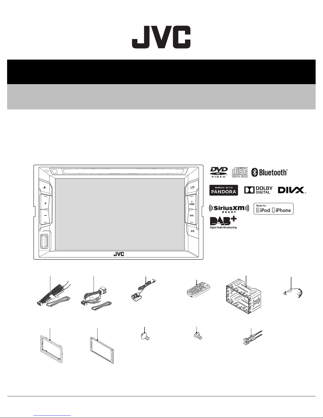
MONITOR WITH DVD RECEIVER
MA601<Rev.001>201410SERVICE MANUAL
KW-V11E, KW-V11EE, KW-V11EU, KW-V11J, KW-V11JW,
KW-V11U, KW-V11UI, KW-V215DBTE, KW-V21BTA,
KW-V21BTE, KW-V21BTEE, KW-V21BTEU, KW-V21BTJ,
KW-V21BTJW, KW-V21BTU, KW-V21BTUI
DC cord
(QAM1561-001)
Escutcheon
(B9H-0001-00)
COPYRIGHT © 2014 JVC KENWOOD Corporation
DC cord
(QAM1562-001)
Escutcheon
(B9H-0002-00)
COPYRIGHT © 2014 JVC KENWOOD Corporation
Microphone
(QAN0137-001)
(3m)
Screw (M5x8)
(QYSTSP5008ZA) x6
Lead free solder used in the board (material: Sn-Ag-Cu, melting point: 219 Centigrade)
Lead free solder used in the board (material: Sn-Cu, melting point: 230 Centigrade)
Remote control
(A7A-0006-00)
Screw (M5x8)
(QYSSSP5008ZA) x6
Mounting assy
(J2C-0006-00)
Lever
(D1A-0007-00) x2
Car cable
(QAM1419-001)
No.MA601<Rev.001>
2014/10

SPECIFICATION
For US
Monitor section
Picture Size (W × H) 6.2 inches (diagonal) wide 137.5 mm × 77.2 mm (5-7/16" × 3-1/16")
Display System Transparent TN LCD panel
Drive System TFT active matrix system
Number of Pixels 1 152 000 (800H × 480V × RGB)
Effective Pixels 99.99%
Pixel Arrangement RGB striped arrangement
Back Lighting LED
DVD player section
D/A Converter 24 bit
Audio Decoder Linear PCM/Dolby Digital/MP3/WMA/WAV
Video Decoder MPEG1/MPEG2/DivX*/JPEG
* Only for KW-V21BT Region 4/KW-V11 Region 4.
Wow & Flutter Below Measurable Limit
Frequency
Response
Total Harmonic Distortion 0.010% (1 kHz)
Signal to Noise Ratio 99 dB (DVD-Video 96 kHz)
Dynamic Range 99 dB (DVD-Video 96 kHz)
Disc Format DVD-Video/VIDEO-CD/CD-DA
Sampling frequency 44.1 kHz/48 kHz/96 kHz
Quantifying Bit Number 16/20/24 bit
USB interface section
USB Standard USB 2.0 Full Speed
Compatible Devices Mass storage class
File System FAT 12/16/32
Maximum Power Supply Current DC 5 V 1 A
D/A Converter 24 bit
Audio Decoder MP3/WMA/WAV
Video Decoder MPEG1/MPEG2/DivX*/JPEG
Bluetooth section (For KW-V21BT)
Technology Bluetooth 2.1 + EDR
Frequency 2.402 GHz - 2.480 GHz
Output Power +4 dBm (MAX), 0 dBm (AVE), Power Class2
Maximum Communication range Line of sight approx. 10 m (32.8 ft)
Audio Codec SBC
Profile HFP (Hands Free Profile) 1.5
96 kHz Sampling 20 Hz to 22 000 Hz
48 kHz Sampling 20 Hz to 22 000 Hz
44.1 kHz Sampling 20 Hz to 20 000 Hz
* Only for KW-V21BT Region 4/KW-V11 Region 4.
SPP (Serial Port Profile) 1.1
SDP (Service Discovery Profile)
A2DP (Advanced Audio Distribution Profile) 1.2
AVRCP (Audio/Video Remote Control Profile) 1.3
OPP (Object Push Profile)
PBAP (Phonebook Access Profile) 1.0
GAP (Generic Access Profile)
(No.MA601<Rev.001>)2/30

FM tuner section
Frequency Range With channel interval set to 200 kHz: 87.9 MHz to 107.9 MHz
With channel interval set to 50 kHz 87.5 MHz to 108.0 MHz
Usable Sensitivity (S/N: 30 dB Dev 22.5 kHz) 7.2 dBf (0.63 µV/75 Ω)
Quieting Sensitivity (S/N: 46 dB Dev 22.5 kHz) 15.2 dBf (1.58 µV/75 Ω)
Frequency Response (± 3.0 dB) 30 Hz - 15 kHz
Signal to Noise Ratio 68 dB (MONO)
Selectivity (± 400 kHz) ≥ 80 dB
Stereo Separation 40 dB (1 kHz)
AM tuner section
Frequency Range (10 kHz) 530 kHz to 1 700 kHz
Usable Sensitivity 29 dBµ
Video section
Color System of External Video Input NTSC/PAL
External Video Input Level (RCA/mini jack) 1 Vp-p/ 75 Ω
Video Output Level (RCA jack) 1 Vp-p/ 75 Ω
Audio section
Maximum Power (Front & Rear) 50 W × 4
Full Bandwidth Power (Front & Rear)(4 Ω, 14.4 V, 1% THD) 22 W × 4
Preout Level 4 V/10 kΩ
Preout Impedance ≤ 600 Ω
Speaker Impedance 4 Ω - 8 Ω
Parametric Equalizer (5 Band) Bass: 63 Hz, 80 Hz, 100 Hz, 125 Hz, ±10 dB
Mid Bass: 200 Hz, 250 Hz, 315 Hz, 400 Hz, ±10 dB
Mid: 0.63 kHz, 0.8 kHz, 1.0 kHz, 1.25 kHz, ±10 dB
Mid High: 2.0 kHz, 2.5 kHz, 3.15 kHz, 4.0 kHz, ±10 dB
High: 6.3 kHz, 8.0 kHz, 10.0 kHz, 12.5 kHz, ±10 dB
General
Operating Voltage 14.4 V (10.5 V - 16 V allowable)
Maximum Current Consumption 10 A
Installation Dimensions (W × H × D) 178 mm × 100 mm × 162 mm (7-1/16” × 3-15/16” × 6-7/16”) (Region 1)
182 mm × 111 mm × 160 mm (7-3/16” × 4-3/8” × 6-5/16”) (Region 4)
Operational Temperature Range -10°C to +60°C
Weight (Main Unit) 1.6 kg (3.6 lbs) (Region 1)
1.9 kg (4.2 lbs) (Region 4)
• Design and specifications are subject to change without notice.
(No.MA601<Rev.001>)3/30

SPECIFICATION
For Europe
Monitor section
Picture Size (W × H) 6.2 inches (diagonal) wide 137.5 mm × 77.2 mm
Display System Transparent TN LCD panel
Drive System TFT active matrix system
Number of Pixels 1 152 000 (800H × 480V × RGB)
Effective Pixels 99.99%
Pixel Arrangement RGB striped arrangement
Back Lighting LED
DVD player section
D/A Converter 24 bit
Audio Decoder Linear PCM/Dolby Digital/MP3/WMA/WAV
Video Decoder MPEG1/MPEG2/DivX/JPEG
Wow & Flutter Below Measurable Limit
Frequency Response 96 kHz Sampling 20 Hz - 22,000 Hz
48 kHz Sampling 20 Hz - 22,000 Hz
44.1 kHz Sampling 20 Hz - 20,000 Hz
Total Harmonic Distortion 0.010% (1 kHz)
Signal to Noise Ratio 99 dB (DVD-Video 96 kHz)
Dynamic Range 99 dB (DVD-Video 96 kHz)
Disc Format DVD-Video/VIDEO-CD/CD-DA
Sampling frequency 44.1 kHz/48 kHz/96 kHz
Quantifying Bit Number 16/20/24 bit
USB interface section
USB Standard USB 2.0 Full Speed
Compatible Devices Mass storage class
File System FAT 12/16/32
Maximum Power Supply Current DC 5 V 1 A
D/A Converter 24 bit
Audio Decoder MP3/WMA/WAV
Video Decoder MPEG1/MPEG2/DivX/JPEG
Bluetooth section (For KW-V21BT/KW-V215DBT)
Technology Bluetooth 2.1 + EDR
Frequency 2.402 GHz - 2.480 GHz
Output Power +4 dBm (MAX), 0 dBm (AVE), Power Class2
Maximum Communication Range Line of sight approx. 10 m
Audio Codec SBC
Profile HFP (Hands Free Profile) 1.5
SPP (Serial Port Profile) 1.1
SDP (Service Discovery Profile)
A2DP (Advanced Audio Distribution Profile) 1.2
AVRCP (Audio/Video Remote Control Profile) 1.3
OPP (Object Push Profile)
PBAP (Phonebook Access Profile)1.0
GAP (Generic Access Profile)
(No.MA601<Rev.001>)4/30

Digital tuner (DAB) section (For KW-V215DBT)
Frequency Range L-BAND: 1 452.960 MHz - 1 490.624 MHz
BAND III: 174.928 MHz - 239.200 MHz
Sensitivity -100 dBm
Signal to Noise Ratio 90 Db
DAB Aerial Connector Connector type: SMB
Output Voltage: 14.4 V (11 V - 16 V allowable)
Maximum Current: <100 mA
FM tuner section
Frequency Range (50 kHz) 87.5 MHz to 108.0 MHz
Usable Sensitivity (S/N: 30 dB Dev 22.5 kHz) 6.2 dBf (0.56 µV/75 Ω)
Quieting Sensitivity (S/N: 46 dB Dev 22.5 kHz) 15.2 dBf (1.58 µV/75 Ω)
Frequency Response (± 3.0 dB) 30 Hz - 15 kHz
Signal to Noise Ratio 68 dB (MONO)
Selectivity (± 400 kHz) ≥ 80 dB
Stereo Separation 40 dB (1 kHz)
LW tuner section
Frequency Range (9 kHz) 153 kHz to 279 kHz
Usable Sensitivity 45 µV
MW tuner section
Frequency Range (9 kHz) 531 kHz - 1 611 kHz
Usable Sensitivity 28.5 µV
Video section
Color System of External Video Input NTSC/PAL
External Video Input Level (RCA/mini jack) 1 Vp-p/ 75 Ω
Video Output Level (RCA jack) 1 Vp-p/ 75 Ω
Analog RGB input (Only for EU ver.) 0.7 Vp-p/75 Ω
Audio section
Maximum Power (Front & Rear) 50 W × 4
Full Bandwidth Power (Front & Rear)
(at less than 1% THD))
30 W × 4 (E Ver.)
22 W × 4 (EU Ver.)
Preout Level 4 V/10 k Ω
Preout Impedance ≤ 600 Ω
Speaker Impedance 4 Ω - 8 Ω
Parametric Equalizer (5 Band) Bass: 63 Hz, 80 Hz, 100 Hz, 125 Hz, ±10 dB
Mid Bass: 200 Hz, 250 Hz, 315 Hz, 400 Hz, ±10 dB
Mid: 0.63 kHz, 0.8 kHz, 1.0 kHz, 1.25 kHz, ±10 dB
Mid High: 2.0 kHz, 2.5 kHz, 3.15 kHz, 4.0 kHz, ±10 dB
High: 6.3 kHz, 8.0 kHz, 10.0 kHz, 12.5 kHz, ±10 dB
General
Operating Voltage 14.4 V (10.5 V - 16 V allowable)
Maximum Current Consumption 10 A
Installation Dimensions (W × H × D) 182 mm × 111 mm × 160 mm (E Ver.)
178 mm × 100 mm × 162 mm (EU Ver.)
Operational Temperature Range -10°C - +60°C
Weight (Main Unit) 1.9 kg (E Ver.)
1.6 kg (EU Ver.)
• Design and specifications are subject to change without notice.
(No.MA601<Rev.001>)5/30

SPECIFICATION
For ASIA
Monitor section
Picture Size (W × H) 6.2 inches (diagonal) wide 137.5 mm × 77.2 mm
Display System Transparent TN LCD panel
Drive System TFT active matrix system
Number of Pixels 1 152 000 (800H × 480V × RGB)
Effective Pixels 99.99%
Pixel Arrangement RGB striped arrangement
Back Lighting LED
DVD player section
D/A Converter 24 bit
Audio Decoder Linear PCM/Dolby Digital/MP3/WMA /WAV
Video Decoder MPEG1/MPEG2/DivX/JPEG
Wow & Flutter Below Measurable Limit
Frequency Response 96 kHz Sampling 20 Hz - 22 000 Hz
48 kHz Sampling 20 Hz - 22 000 Hz
44.1 kHz Sampling 20 Hz - 20 000 Hz
Total Harmonic Distortion 0.010% (1 kHz)
Signal to Noise Ratio 99 dB (DVD-Video 96 kHz)
Dynamic Range 99 dB (DVD-Video 96 kHz)
Disc Format DVD-Video/VIDEO-CD/CD-DA
Sampling frequency 44.1 kHz/48 kHz/96 kHz
Quantifying Bit Number 16/20/24 bit
USB interface section
USB Standard USB 2.0 High Speed
Compatible Devices Mass storage class
File System FAT 12/16/32
Maximum Power Supply Current DC 5 V 1 A
D/A Converter 24 bit
Audio Decoder MP3/WMA /WAV
Video Decoder MPEG1/MPEG2/DivX/JPEG
Bluetooth section (For KW-V21BT)
Technology Bluetooth 2.1 + EDR
Frequency 2.402 GHz - 2.480 GHz
Output Power +4 dBm (MAX), 0 dBm (AVE), Power Class2
Maximum Communication range Line of sight approx. 10 m
Audio Codec SBC
Profile HFP (Hands Free Profile) 1.5
SPP (Serial Port Profile) 1.1
SDP (Service Discovery Profile)
A2DP (Advanced Audio Distribution Profile) 1.2
AVRCP (Audio/Video Remote Control Profile) 1.3
OPP (Object Push Profile)
PBAP (Phonebook Access Profile) 1.0
GAP (Generic Access Profile)
(No.MA601<Rev.001>)6/30

FM tuner section
Frequency Range (50 kHz) 87.5 MHz to 108.0 MHz
Usable Sensitivity (S/N: 30 dB Dev 22.5 kHz) 6.2 dBf (0.56 µV/75 Ω)
Quieting Sensitivity (S/N: 46 dB Dev 22.5 kHz) 15.2 dBf (1.58 µV/75 Ω)
Frequency Response (± 3.0 dB) 30 Hz - 15 kHz
Signal to Noise Ratio 68 dB (MONO)
Selectivity (± 400 kHz) ≥ 80 dB
Stereo Separation 40 dB (1 kHz)
AM tuner section (For U and A Ver.)
Frequency Range (9 kHz) 531 kHz to 1 611 kHz
Usable Sensitivity 29 dBµ
LW tuner section (For UI Ver.)
Frequency Range (9 kHz) 153 kHz - 279 kHz
Usable Sensitivity 45 dBµ
MW tuner section (For UI Ver.)
Frequency Range (9 kHz) 531 kHz - 1 611 kHz
Usable Sensitivity 28.5 dBµ
Video section
Color System of External Video Input NTSC/PAL
External Video Input Level (RCA/mini jack) 1 Vp-p/ 75 Ω
Video Output Level (RCA jack) 1 Vp-p/ 75 Ω
Analog RGB input (Only for KW-V21BTU) 0.7 Vp-p/75 Ω
Audio section
Maximum Power (Front & Rear) 50 W × 4
Full Bandwidth Power (Front & Rear)
22 W × 4
(at less than 1% THD)
Preout Level 4 V/10 kΩ
Preout Impedance ≤ 600 Ω
Speaker Impedance 4 Ω - 8 Ω
Parametric Equalizer (5 Band) Bass: 63 Hz, 80 Hz, 100 Hz, 125 Hz, ±10 dB
Mid Bass: 200 Hz, 250 Hz, 315 Hz, 400 Hz, ±10 dB
Mid: 0.63 kHz, 0.8 kHz, 1.0 kHz, 1.25 kHz, ±10 dB
Mid High: 2.0 kHz, 2.5 kHz, 3.15 kHz, 4.0 kHz, ±10 dB
High: 6.3 kHz, 8.0 kHz, 10.0 kHz, 12.5 kHz, ±10 dB
General
Operating Voltage 14.4 V (10.5 V to 16 V allowable)
Maximum Current Consumption 10 A
Installation Dimensions (W × H × D) 178 mm × 100 mm × 162 mm
Operational Temperature Range -10°C - +60°C
Weight (Main Unit) 1.6 kg
• Design and specifications are subject to change without notice.
(No.MA601<Rev.001>)7/30
SECTION 1
PRECAUTION
1.1 Safety Precautions
(1) This design of this product contains special hardware and
many circuits and components specially for safety purposes. For continued protection, no changes should be made
to the original design unless authorized in writing by the
manufacturer. Replacement parts must be identical to
those used in the original circuits. Services should be performed by qualified personnel only.
(2) Alterations of the design or circuitry of the product should
not be made. Any design alterations of the product should
not be made. Any design alterations or additions will void
the manufacturers warranty and will further relieve the
manufacture of responsibility for personal injury or property
damage resulting therefrom.
(3) Many electrical and mechanical parts in the products have
special safety-related characteristics. These characteristics are often not evident from visual inspection nor can the
protection afforded by them necessarily be obtained by using replacement components rated for higher voltage, wattage, etc. Replacement parts which have these special
safety characteristics are identified in the Parts List of Service Manual. Electrical components having such features
are identified by shading on the schematics and by ( ) on
the Parts List in the Service Manual. The use of a substitute
replacement which does not have the same safety characteristics as the recommended replacement parts shown in
the Parts List of Service Manual may create shock, fire, or
other hazards.
(4) The leads in the products are routed and dressed with ties,
clamps, tubings, barriers and the like to be separated from
live parts, high temperature parts, moving parts and/or
sharp edges for the prevention of electric shock and fire
hazard. When service is required, the original lead routing
and dress should be observed, and it should be confirmed
that they have been returned to normal, after reassembling.
1.2 Warning
(1) This equipment has been designed and manufactured to
meet international safety standards.
(2) It is the legal responsibility of the repairer to ensure that
these safety standards are maintained.
(3) Repairs must be made in accordance with the relevant
safety standards.
(4) It is essential that safety critical components are replaced
by approved parts.
(5) If mains voltage selector is provided, check setting for local
voltage.
1.3 Caution
Burrs formed during molding may be left over on some parts
of the chassis.
Therefore, pay attention to such burrs in the case of preforming repair of this system.
1.4 Critical parts for safety
In regard with component parts appearing on the silk-screen
printed side (parts side) of the PWB diagrams, the parts that are
printed over with black such as the resistor ( ), diode ( )
and ICP ( ) or identified by the " " mark nearby are critical
for safety. When replacing them, be sure to use the parts of the
same type and rating as specified by the manufacturer.
(This regulation dose not Except the J and C version)
1.5 Remote control
The Lithium battery is in danger of explosion if replaced incorrectly. Replace it only with the same or equivalent type.
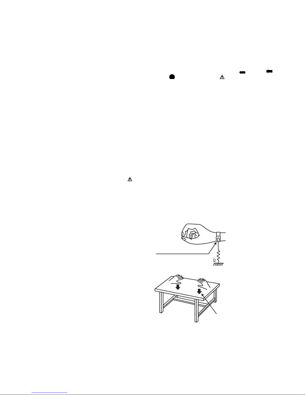
1.6 Preventing static electricity
Electrostatic discharge (ESD), which occurs when static electricity stored in the body, fabric, etc. is discharged, can destroy the
laser diode in the traverse unit (optical pickup). Take care to prevent this when performing repairs.
1.6.1 Grounding to prevent damage by static electricity
Static electricity in the work area can destroy the optical pickup
(laser diode) in devices such as laser products.
Be careful to use proper grounding in the area where repairs are
being performed.
(1) Ground the workbench
Ground the workbench by laying conductive material (such
as a conductive sheet) or an iron plate over it before placing the traverse unit (optical pickup) on it.
(2) Ground yourself
Use an anti-static wrist strap to release any static electricity
built up in your body.
(caption)
Anti-static wrist strap
1M
Conductive material
(conductive sheet) or iron plate
(3) Handling the optical pickup
• In order to maintain quality during transport and before
installation, both sides of the laser diode on the replacement optical pickup are shorted. After replacement, return the shorted parts to their original condition.
(Refer to the text.)
• Do not use a tester to check the condition of the laser diode in the optical pickup. The tester's internal power
source can easily destroy the laser diode.
(No.MA601<Rev.001>)8/30
1.7 Handling the traverse unit (optical pickup)
(1) Do not subject the traverse unit (optical pickup) to strong shocks, as it is a sensitive, complex unit.
(2) Cut off the shorted part of the flexible cable using nippers, etc. after replacing the optical pickup. For specific details, refer to the
replacement procedure in the text. Remove the anti-static pin when replacing the traverse unit. Be careful not to take too long a
time when attaching it to the connector.
(3) Handle the flexible cable carefully as it may break when subjected to strong force.
(4) I t is not possible to adjust the semi-fixed resistor that adjusts the laser power. Do not turn it.
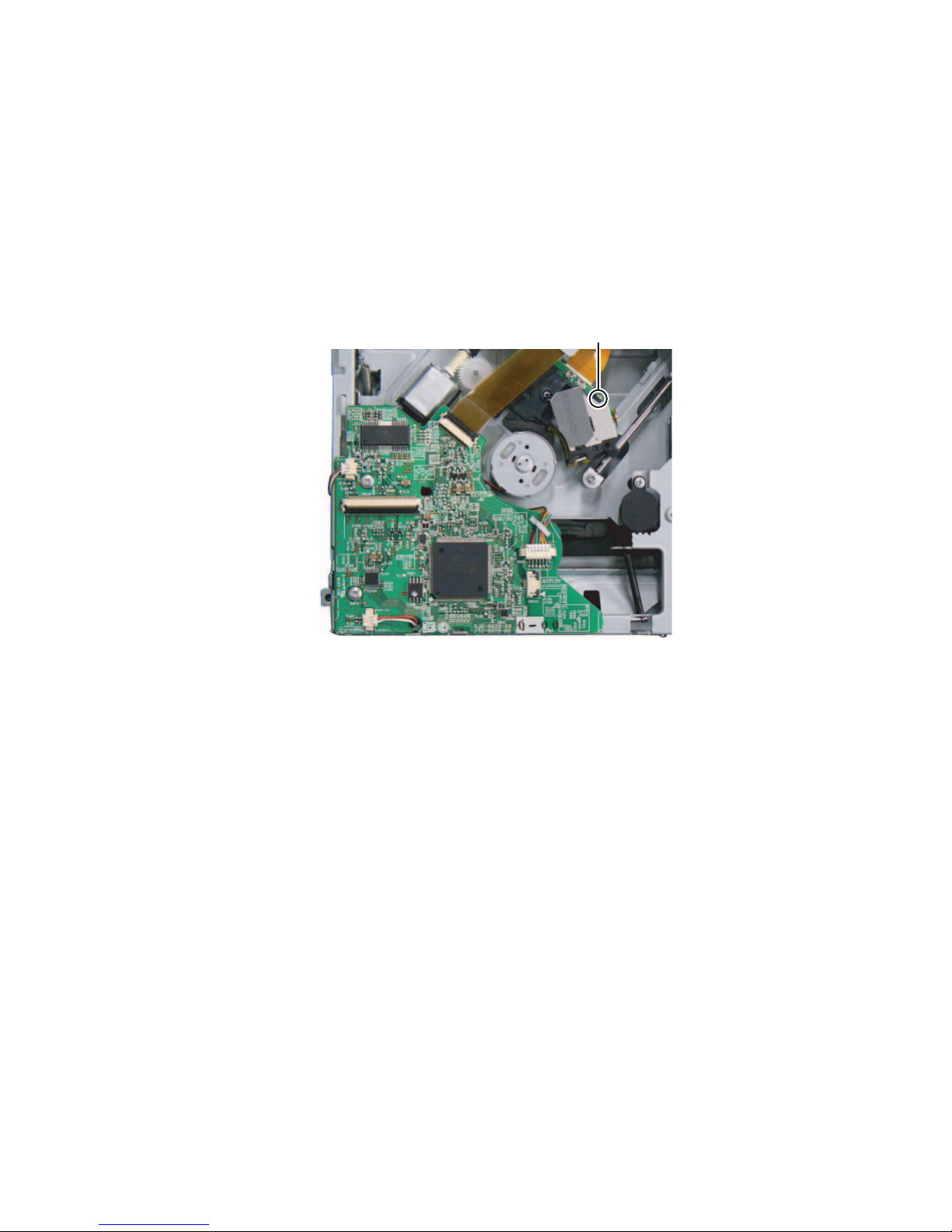
1.8 Attention when traverse unit is decomposed
*Please refer to "Disassembly method" in the text for the pickup unit.
• Apply solder to the short land sections before the FPC wire is disconnected from the connector on the DVD mecha board. (If the
FPC wire is disconnected without applying solder, the pickup may be destroyed by static electricity.)
• In the assembly, be sure to remove solder from the short land sections after connecting the FPC wire.
Short land section
(No.MA601<Rev.001>)9/30
 Loading...