

Page 1

DVD PLAYER &
VIDEO CASSETTE RECORDER
HR-XVC32SUJ
IntroductionPreparation
VCR Deck
Operations on
INSTRUCTIONS
LPT1042-001A
DVD Deck
Operations on
Advanced OperationsAdditional Information
Page 2

Enjoy Playback of DVD & Video Cassette
Enjoy Playback of DVD & Video Cassette
All in This Combo Unit
All in This Combo Unit
Region code of DVD VIDEO
This unit can play back DVD VIDEO discs whose
region code numbers include “1.”
Examples of playable DVD VIDEO discs:
2
ALL
The unit’s region code is printed on the rear of the unit.
2
1
21
1
4
3
2
1
5
4
Supplied accessories
If anything is missing, consult your dealer immediately.
• RF cable
• Remote
• “AA” battery x 2
3
6
• Conversion plug
Page 3

Introduction
SAFETY FIRST ........................................................... 4
Buttons, Connectors, and Indicators ............................ 7
Preparation
Connections
Basic Connections ................................................... 9
Component Video Connection ................................ 10
Initial Settings
Plug&Play Set .......................................................... 11
Monitor Set (DVD deck) ........................................... 12
Language Set .......................................................... 12
Clock Set ................................................................. 14
Tuner Set ................................................................. 15
.............................................................. 9
.......................................................... 11
Operations on VCR Deck
Playback on VCR Deck
Basic Playback ........................................................ 16
Playback Features ................................................... 18
Recording
................................................................. 20
Basic Recording ...................................................... 20
Recording Features ................................................. 20
Timer Recording
Express Timer Programming ................................... 21
Satellite Auto Recording .......................................... 23
............................................... 16
........................................................ 21
Operations on DVD Deck
IntroductionPreparation
VCR Deck
Operations on
Playback on DVD Deck
Basic Playback ........................................................ 24
Playback Features ................................................... 24
Menu Bar Functions
MP3/JPEG Files Playback
............................................... 24
................................................ 26
...................................... 27
Advanced Operations
Editing
...................................................................... 28
Editing with another video recorder
or a camcorder ..................................................... 28
Dubbing from DVD to VCR ...................................... 29
System Connections
Other Functions
Subsidiary Settings
Mode Set (VCR deck) .............................................. 32
Mode Set (DVD deck) .............................................. 34
................................................... 30
......................................................... 31
.................................................... 32
Additional Information
Troubleshooting
Questions & Answers
Language Code List
Specifications
List of Terms
........................................................ 36
................................................. 37
.................................................... 38
............................................................ 38
............................................................. 39
DVD Deck
Operations on
Advanced OperationsAdditional Information
3
Page 4
Dear Customer,
Thank you for purchasing the JVC DVD player & VHS
video cassette recorder. Before use, please read the
safety information and precautions to ensure safe use
of your new unit.
IMPORTANT
7 Please read the various precautions on page 4 and
5 before installing or operating the unit.
7 It may be unlawful to record or play back
copyrighted material without the consent of the
copyright owner.
SAFETY FIRST
CAUTIONS
WARNING: DANGEROUS VOLTAGE INSIDE
WARNING: TO PREVENT FIRE OR SHOCK HAZARD,
DO NOT EXPOSE THIS UNIT TO RAIN OR
MOISTURE.
The POWER
mains power from the unit, but switches operating
current on and off. “
standby and “
CAUTION:
A DVD/VCR IS A CLASS 1 LASER PRODUCT.
HOWEVER THIS DVD/VCR USES A VISIBLE
LASER BEAM WHICH COULD CAUSE
HAZARDOUS RADIATION EXPOSURE IF
DIRECTED. BE SURE TO OPERATE THE UNIT
CORRECTLY AS INSTRUCTED.
WHEN THIS DVD/VCR IS PLUGGED INTO THE
WALL OUTLET, DO NOT PLACE YOUR EYES
CLOSE TO THE OPENING OF THE DISC TRAY
AND OTHER OPENINGS TO LOOK INTO THE
INSIDE OF THIS DVD/VCR.
USE OF CONTROLS OR ADJUSTMENTS OR
PERFORMANCE OF PROCEDURES OTHER THAN
THOSE SPECIFIED HEREIN MAY RESULT IN
HAZARDOUS RADIATION EXPOSURE.
DO NOT OPEN COVERS AND DO NOT REPAIR
YOURSELF. REFER SERVICING TO QUALIFIED
PERSONNEL.
button does not completely shut off
” shows electrical power
” shows ON.
CAUTION
7 When you are not using the unit for a long period
of time, it is recommended that you disconnect the
power cord from the AC outlet.
7 Dangerous voltage inside. Refer internal servicing
to qualifi ed service personnel. To prevent electric
shock or fi re hazard, remove the power cord from
the AC outlet prior to connecting or disconnecting
any signal lead or aerial.
7 Changes or modifi cations not approved by JVC
could void user’s authority to operate the
equipment.
The rating plate and safety caution are on the rear of
the unit.
This unit is produced to comply with Standard IEC
60065.
POWER SYSTEM:
This set operates on voltage of AC 110 – 220V
50/60 Hz with automatic switching.
Use the conversion plug (provided) depending on the
type of your AC WALL outlet.
,
CLASS 1 LASER PRODUCT
REPRODUCTION OF LABELS
WARNING LABEL INSIDE OF THE UNIT
When the equipment is installed in a cabinet or a shelf, make sure that it has suffi cient space on all sides to allow for
ventilation (10 cm or more on both sides, on top and at the rear.)
When discarding batteries, environmental problems must be considered and the local rules or laws governing the
disposal of these batteries must be followed strictly.
4
Page 5
• Manufactured under license from Dolby
Laboratories. “Dolby” and the double-D symbol are
trademarks of Dolby Laboratories.
• “DTS” and “DTS 2.0 + Digital Out” are trademarks
of Digital Theater Systems, Inc.
• Cassettes marked “VHS” (or “S-VHS”) can be used
with this unit. However, S-VHS recording is not
possible with this model.
• This model is equipped with SQPB (S-VHS QUASI
PLAYBACK) that makes it possible to play back SVHS recordings with regular VHS resolution.
• HQ VHS is compatible with existing VHS
equipment.
• This product incorporates copyright protection
technology that is protected by U.S. patents and
other intellectual property rights. Use of this
copyright protection technology must be authorized
by Macrovision, and is intended for home and
other limited viewing uses only unless otherwise
authorized by Macrovision. Reverse engineering or
disassembly is prohibited.
Failure to heed the following precautions may
result in damage to the unit, Remote or video
cassette.
1. DO NOT place the unit —
– in an environment prone to extreme
temperatures or humidity.
– in direct sunlight.
– in a dusty environment.
– in an environment where strong magnetic fields
are generated.
– on a surface that is unstable or subject to
vibration.
2. DO NOT block the unit’s ventilation openings
or holes.
(If the ventilation openings or holes are blocked
by a newspaper or cloth, etc., the heat may not be
able to get out.)
3. DO NOT place heavy objects on the unit or
Remote.
4. DO NOT place anything which might spill on
top of the unit or Remote.
(If water or liquid is allowed to enter this
equipment, fi re or electric shock may be caused.)
5. DO NOT expose the apparatus to dripping or
splashing.
6. DO NOT use this equipment in a bathroom or
places with water. Also DO NOT place any
containers fi lled with water or liquids (such as
cosmetics or medicines, fl ower vases, potted
plants, cups, etc.) on top of this unit.
7. DO NOT place any naked fl ame sources, such
as lighted candles, on the apparatus.
8. AVOID violent shocks to the unit during
transport.
MOISTURE CONDENSATION
Moisture in the air will condense on the unit when
you move it from a cold place to a warm place, or
under extremely humid conditions—just as water
droplets form in the surface of a glass fi lled with
cold liquid. Moisture condensation on the head drum
will cause damage to the tape. In conditions where
condensation may occur, keep the unit turned on for
a few hours to let the moisture dry.
ATTENTION
To mobile phone users:
Using a mobile phone in the vicinity of the unit may
cause picture vibration on the TV screen or change
the screen to a blue back display.
On placing the unit:
Some TVs or other appliances generates strong
magnetic fi elds. Do not place such appliance on top
of the unit as it may cause picture disturbance.
Video heads cleaning
The heads get dirty in the following cases:
• in an environment prone to extreme temperature or
humidity
• in a dusty environment
• fl aw, dirt or mold on video tapes
• continuous usage for a long time
Use a dry cleaning cassette — ECL-3F — when:
• Rough, poor picture appears while a tape is played
back.
• The picture is unclear or no picture appears.
• “USE CLEANING CASSETTE” appears on the
screen (only with “SUPERIMPOSE” set to “ON” (
☞ pg. 32)).
BEFORE YOU INSTALL YOUR NEW UNIT . . .
. . . please read the sections/literature listed below.
• “CAUTIONS” on page 4.
HOW TO USE THIS INSTRUCTION MANUAL
• All major sections and subsections are listed in
the Table Of Contents on page 3. Use this when
searching for information on a specifi c procedure or
feature.
• Buttons, connectors, and indicators on the front and
rear panel, the front display panel, and the Remote
are illustrated on pages 7 and 8.
• The ☞ mark signals a reference to another page for
instructions or related information.
• Operation buttons necessary for the various
procedures are indicated through the use of
illustrations at the bottom of pages.
IntroductionPreparation
VCR Deck
Operations on
DVD Deck
Operations on
Advanced OperationsAdditional Information
5
Page 6

Usable cassette
Full-Size VHS
T-30 (ST-30**)
T-60 (ST-60**)
T90
T-120 (ST-120**)
T-160 (ST-160**)
ST-210**
Compact VHS*
TC-20 (ST-C20**)
TC-30 (ST-C30**)
TC-40 (ST-C40**)
* Compact VHS camcorder recordings can be played
on this unit. Simply place the recorded cassette into a
VHS Cassette Adapter and it can be used just like
any full-sized VHS cassette.
** This unit can record on regular VHS and Super VHS
cassettes. However, it will record regular VHS signals
only.
• S-VHS recording is not possible with this unit.
• This unit is equipped with SQPB (S-VHS QUASI
PLAYBACK) that lets you watch tapes recorded in
the S-VHS format with regular VHS resolution.
• SQPB does not deliver Super VHS resolution.
Playable discs
• DVD VIDEO, Audio CD, Video CD, SVCD (8 cm/12 cm
disc)
• DVD-R/-RW written in the DVD VIDEO mode
• CD-R/RW written in the SVCD, Video CD or Audio CD
format
• CD-R/RW written in MP3/JPEG in accordance with the
“ISO 9660” format
Supported Digital audio formats:
Linear PCM, Dolby Digital, DTS (Digital Theater
Systems)*
NOTES
• If a disc gets dirty, scratched or warped, or due to the disc
characteristics or recording conditions, the player may not
be able to play back such discs.
• The player can play back audio signals recorded in
MIX-MODE CD, CD-G, CD-EXTRA and CD TEXT.
• With some discs, operations may not be possible.
* To play back DTS-encoded DVD VIDEO or DTS-
encoded Audio CD discs correctly, connect the
player to an amplifier with a built-in DTS decoder.
Unplayable discs
If you try to play back discs listed below, noise may be
generated and causes damage to speakers.
• DVD-RW written in the VR mode
• DVD-ROM, DVD-RAM, DVD AUDIO, CD-ROM,
PHOTO CD, SACD
• Unfinalized discs
• Discs of irregular shape or discs with tape, seals or
paste on either the label side or playback side.
Playing back these discs may damage the player.
The Non-DVD side of a “DualDisc” does not comply with
the “Compact Disc Digital Audio” standard.
Therefore, the use of Non-DVD side of a DualDisc on
this product may not be recommended.
6
Page 7

Buttons, Connectors, and Indicators
Front View
POWER
0 EJECT
(Cassette)
VIDEO/AUDIO input connectors
Front Display Panel
Operation Mode Indicator
Cassette loading slot
Remote sensor
Multi-information window*VHS Indicator
VCR Indicator Progressive Mode Indicator
VCR/DVD 7 STOP 3 PLAYDisc tray
“Timer” Indicator
¶ REC
DVD Indicator
FF ¡
1 REW
Satellite Auto Recording
Indicator
0 OPEN/CLOSE
(Disc tray)
CH +/–
PROGRESSIVE SCAN
IntroductionPreparation
VCR Deck
Operations on
* You can change the information by pressing DISPLAY on the Remote as follows:
For VCR deck: Channel/auxiliary input/clock/tape counter information will be displayed.
For DVD deck: The current group/title/track/chapter number(s), time, and status information will be
displayed.
Rear View
Region Number Label
1
DIGITAL AUDIO OUT Connector*
* These connectors are only for DVD deck.
AUDIO/VIDEO OUTPUT ConnectorsAC Power Cord
AUDIO OUTPUT Connectors*
COMPONENT VIDEO OUT Connectors*
VHF/UHF Antenna
Input Connector
VHF/UHF Antenna
Output Connector
DVD Deck
Operations on
Advanced OperationsAdditional Information
7
Page 8
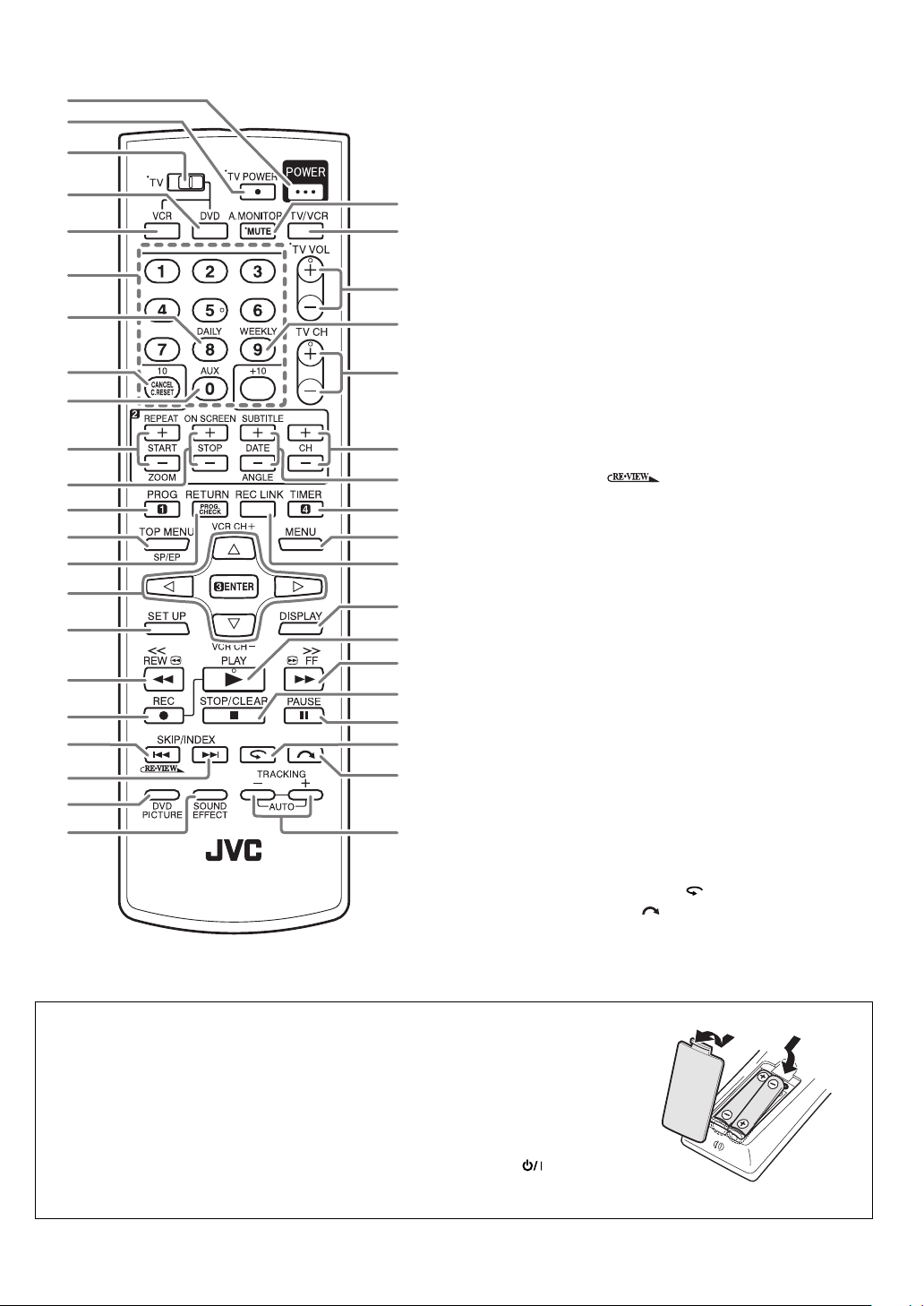
Remote
1
2
3
4
5
6
7
8
9
p
q
w
e
r
t
y
u
i
o
;
a
s
d
f
g
h
j
k
l
/
z
x
c
v
b
n
m
,
.
P
1 Power Button (POWER)
2 TV Power Button (TV POWER)
3 TV/VCR/DVD switch
4 DVD Button
5 VCR Button
6 Number Buttons
7 Daily Button (DAILY)
8 Cancel Button (CANCEL), Reset Button (C.RESET)
9 Auxiliary Button (AUX)
p Start Time Button (START +/–), Repeat Button
(REPEAT), Zooming Button (ZOOM)
q Stop Time Button (STOP +/–), On-Screen Button
(ON SCREEN)
w Programing Button (PROG)
e Top Menu Button (TOP MENU), SP/EP Button
r Program Check Button (PROG. CHECK), Return
Button (RETURN)
t @/#/%/fi Button, ENTER Button, VCR Channel
Button (VCR CH +/–)
y Set Up Button (SET UP)
u Rewind Button (1 REW)
i Record Button (¶ REC)
o Reverse Skip/Index Button (4 SKIP/INDEX),
Review Button (
; Forward Skip/Index Button (¢ SKIP/INDEX)
a DVD Picture Button (DVD PICTURE)
s Sound Effect Button (SOUND EFFECT)
d TV Muting Button (MUTE)/Audio Monitor Button
(A.MONITOR)
f TV/VCR Button
g TV Volume Button (TV VOL+/–)
h Weekly Button (WEEKLY)
j TV Channel Button (TV CH +/–)
k Channel Button (CH +/–)
l Date Button (DATE +/–), Subtitle Button (SUBTITLE),
Angle Button (ANGLE)
/ Timer Button (TIMER)
z Menu Button (MENU)
x Satellite Auto Recording Button (REC LINK)
c Display Button (DISPLAY)
v Play Button (3 PLAY)
b Fast Forward Button (FF ¡)
n Stop Button (7 STOP)/Clear Button* (CLEAR)
* Does not function with this unit.
m Pause Button (8 PAUSE)
, One Touch Replay Button (
. Skip Search Button (
P Tr acking Button (TRACKING +/–)
)
)
)
How to use the Remote
Before use, insert two AA size batteries into the Remote with the polarity (ª and ·)
matched correctly as indicated on the Remote.
• Point the Remote toward the remote sensor.
• The maximum operating distance of the Remote is about 8 m.
The Remote can operate most of your unit’s functions, as well as basic functions of
TV sets of JVC.
Buttons with a small dot on the left side of the name (TV POWER (
VOL+/–, TV CH +/–, MUTE) can also be used to operate a JVC’s TV after setting
the TV/VCR/DVD switch to the left.
), TV/VCR, TV
8
Page 9
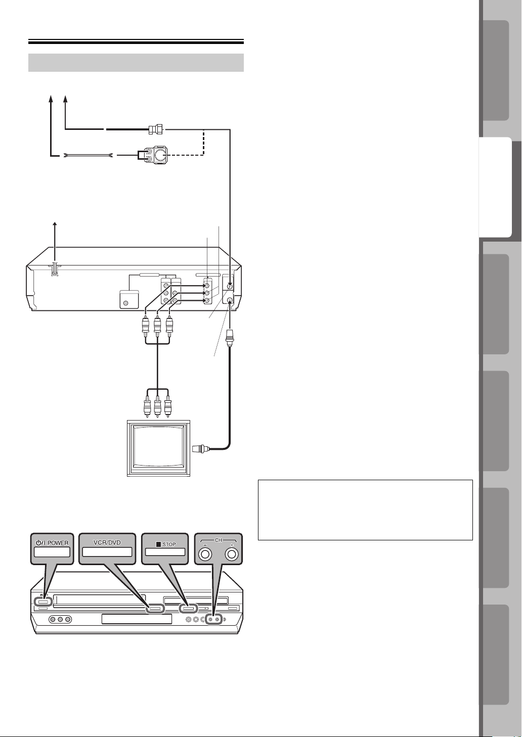
Connections
Basic Connections
Antenna or Cable
Coaxial cable
Flat feeder
AC Outlet
AC Power Cord
Back of unit
Audio/video cable
(not supplied)
To Audio/video
input connectors
Matching transformer
(not supplied)
OUTPUT
VIDEO OUTPUT
VHF/UHF
IN
VHF/UHF OUT
RF cable
(supplied)
To 75 ohm
Terminal
TV
AUDIO
~ Place the unit on a stable, horizontal surface.
Ÿ Connect the unit to TV.
RF Connection
1 Disconnect the TV antenna from the TV.
2 Connect the TV antenna cable to the VHF/UHF
IN connector on the rear panel of the unit.
3 Connect the supplied RF cable between the
VHF/UHF OUT connector on the rear panel of
the unit and the TV’s antenna terminal.
AV Connection
1 Connect the antenna, unit and TV as per “RF
Connection.”
2 Connect an optional audio/video cable between
the AUDIO/VIDEO OUTPUT connectors on the
rear panel of the unit and the TV’s audio/video
input connectors.
• Set your TV to AV mode.
! Plug the end of the AC power cord into an AC outlet.
This unit performs Plug&Play Set automatically. (☞
pg. 11)
The clock and tuner channels will automatically be
set when the antenna is connected and when the
AC power cord is connected to an AC outlet for the
first time. (If “Auto” and the channel indicator are
displayed on the front display panel before the unit is
powered on, the clock and tuner channels are being
set automatically. Wait for the time to be displayed
on the front display panel before turning on the unit.)
⁄ Set the VCR channel.
The VCR channel is the channel on which you can
watch the picture from the unit on the TV only when
using RF connection. With RF connection, set the
VCR channel to “3 CH” or “4 CH.”
• The VCR channel is preset to “3 CH.” Set to “4 CH” if
the Channel 3 is used for broadcasting in your area.
• With AV connection, set the VCR channel to “– CH”
(off).
To set the VCR channel, perform the following steps:
Before performing the following steps:
• Make sure there is no cassette inserted in the unit.
• Make sure the unit is turned on, then press
VCR/DVD on the unit so that the VHS indicator
lights up on the front display panel.
IntroductionPreparation
IntroductionPreparation
VCR Deck
VCR Deck
Operations on
Operations on
DVD Deck
DVD Deck
Operations on
Operations on
1 Press POWER on the unit to turn off the unit,
then press 7 STOP on the unit for more than 5
seconds. “3 CH” appears on the front display
panel.
2 Press CH +/– on the unit to select “3 CH,” “4 CH,”
or “– CH” (off), then press POWER on the unit.
Advanced OperationsAdditional Information
Advanced OperationsAdditional Information
9
9
Page 10

Component Video Connection
(For high-quality DVD pictures)
ATTENTION
Be sure to connect the unit’s VIDEO OUTPUT (DVD/
VCR) connector to the TV’s VIDEO input connector.
Antenna or Cable
Flat feeder
AC Outlet
AC Power Cord
COMPONENT VIDEO OUT
Back of unit
Component
Video cable
(not supplied)
To Component
Video/audio Input
connector
Coaxial cable
AUDIO OUTPUT
Audio cable
(not supplied)
TV
Matching transformer
(not supplied)
AUDIO OUTPUT
VIDEO OUTPUT
Audio/video
(not supplied)
To Audio/video
input connectors
To 75 ohm Terminal
cable
RF cable
(supplied)
VHF/UHF
IN
VHF/UHF
OUT
~ Place the unit on a stable, horizontal surface.
Ÿ Connect the unit to TV.
1 Connect the antenna, unit and TV as per “AV
Connection.” (☞ pg. 9)
2 Connect the unit’s COMPONENT VIDEO OUTPUT
connector to the TV’s component video input
connector.
! Plug the end of the AC power cord into an AC outlet.
This unit performs Plug&Play Set automatically. (☞ pg.
11)
The clock and tuner channels will automatically be set
when the antenna is connected and when the AC power
cord is connected to an AC outlet for the first time. (If
“Auto” and the channel indicator are displayed on the
front display panel before the unit is powered on, the
clock and tuner channels are being set automatically.
Wait for the time to be displayed on the front display
panel before turning on the unit.)
⁄ Set the VCR channel to off.
Before performing the following steps:
• Make sure there is no cassette inserted in the unit.
• Make sure the unit is turned on, then press
VCR/DVD on the unit so that the VHS indicator lights
up on the front display panel.
1 Press POWER on the unit to turn off the unit, then
press 7 STOP on the unit for more than 5 seconds.
“3 CH” appears on the front display panel.
2 Press CH +/– on the unit to select “3 CH,” “4 CH,” or
“– CH” (off), then press POWER on the unit.
NOTES:
• By using the component video connection, you can view
the images in the progressive mode. For switching to the
progressive mode, refer to “Scan Mode Set (DVD deck
only).” (☞ pg. 11)
• To enjoy playback of DVD with the component video
connection, set the TV’s input to the component video input.
10
Page 11
Scan Mode Set (DVD deck only)
This unit supports the progressive scan system as
well as the conventional interlaced scan system.
If your TV equipped with component video
connectors supports the progressive video input,
you can enjoy a high quality picture by setting the
progressive scan mode to active.
• Refer also to the instruction manuals supplied with
your TV.
• If your TV equipped with component video
connectors does not support the progressive
video input, do not change the scan mode to the
“PROGRESSIVE.”
• Turn on the TV and select the VCR channel (or
AV mode).
• Slide the TV/VCR/DVD switch on the Remote to
right.
~ Select the DVD deck.
Press VCR/DVD on the unit so that the DVD
indicator lights up on the front display panel.
Ÿ Switch the mode.
1 Press and hold PROGRESSIVE SCAN on the
unit for more than 3 seconds.
The current scan mode blinks on the front display
panel.
2 While the current scan mode blinks, press @ #
to select “
scan mode) or “
interlaced scan mode), then press ENTER.
• If the current scan mode stops blinking before
you make the setting, start from step 1 again.
NOTE:
When the progressive scan mode is selected, the
Progressive mode indicator ( ) lights up on the front
display panel.
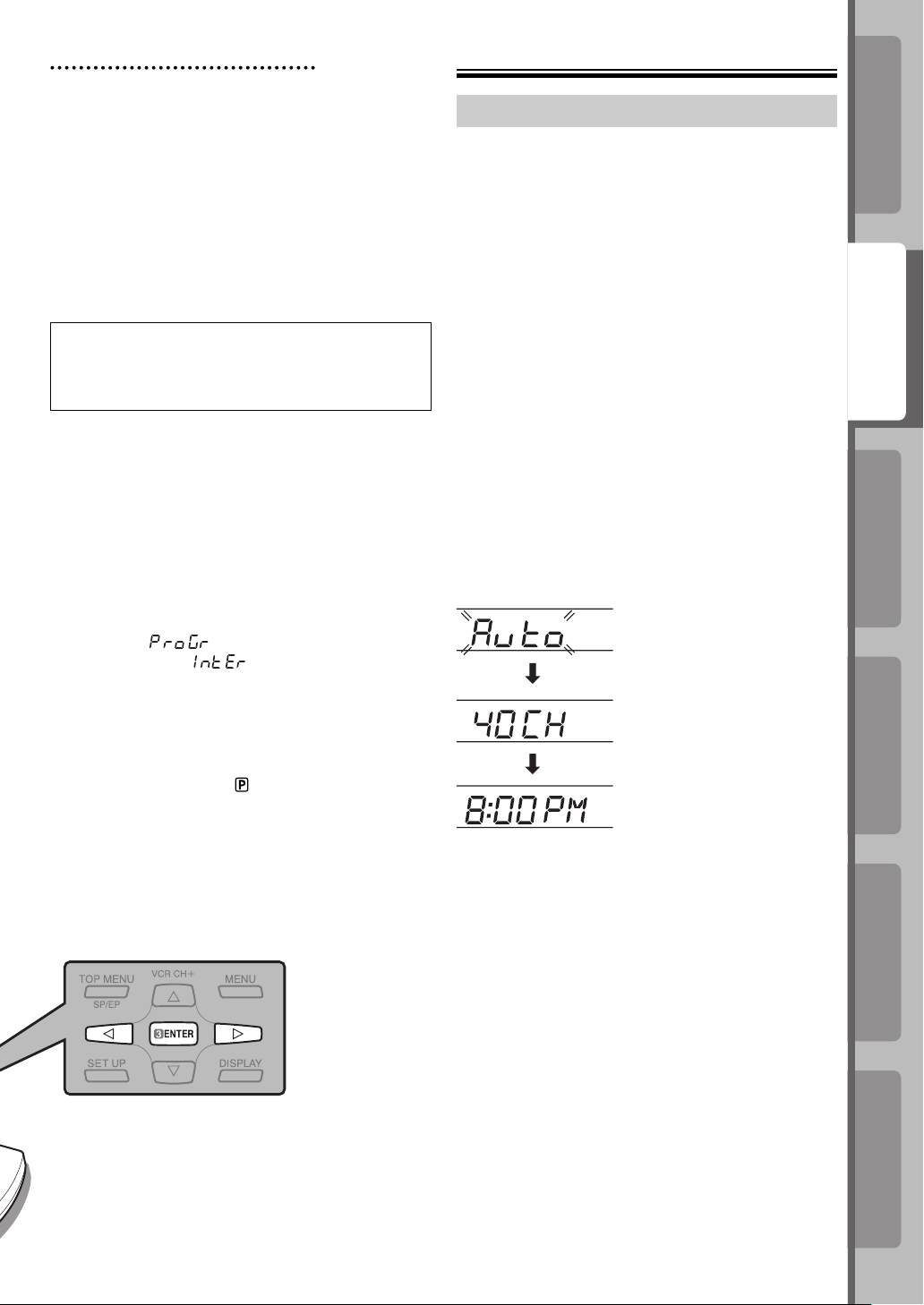
(ProGr)” (for the progressive
(IntEr)” (for the
Initial Settings
Plug&Play Set
This unit sets the clock and tuner channels
automatically when the AC power cord is connected
to an AC outlet for the first time.
The time and date can be set automatically by the
clock setting data transmitted from one of the regular
TV broadcast channels. (We call this TV channel the
“host channel” and it is a PBS channel in your area.)
• The antenna cable must be connected for
Plug&Play set. (☞ pg. 9 and 10)
NOTES
• If you use a cable box, Plug&Play will not function; set
the clock and tuner channels separately. (☞ pg. 14 and
15)
• Depending on areas or reception conditions, the unit
may not receive the Auto clock setting data from the PBS
channel. If this function is taking a considerable amount
of time, it may be necessary to perform the Semiauto or
Manual Clock Set procedure. (☞ pg. 14)
~ Perform Plug&Play set.
Connect the AC power cord to an AC outlet. Do not
turn on the unit. The clock and tuner channels will be
set automatically.
During Initial Auto Clock Set
“Auto” blinks.
During Auto Channel Set
The channel numbers
are displayed as they are
scanned and set.
Plug&Play Completed
The current time is displayed.
IntroductionPreparation
IntroductionPreparation
VCR Deck
VCR Deck
Operations on
Operations on
DVD Deck
DVD Deck
Operations on
Operations on
What to do if Plug&Play set failed
• If an incorrect time is displayed on the front display
panel, you may be receiving the clock setting data of a
PBS channel from an adjacent time zone, or an incorrect
PBS channel from a cable TV system. In this case,
perform “Semiauto Clock Set” or “Manual Clock Set” (☞
pg. 14).
• If “– : – –” appears on the front display panel, your
antenna cable may not be connected to the unit or
there may not be a Host PBS signal available in your
area. Ensure that the antenna cable is connected
correctly. Then turn on and off the unit; Plug&Play set
will be automatically reactivated. If Plug&Play set is
not performed though the antenna cable is connected
correctly, perform “Manual Clock Set” (☞ pg. 14), then
“Auto Channel Set” (☞ pg. 15) or “Manual Channel Set”
(☞ pg. 15).
Advanced OperationsAdditional Information
Advanced OperationsAdditional Information
11
11
Page 12
Initial Settings (continued)
Monitor Set (DVD deck)
You can select the monitor type depending the TV used
when you playback DVD VIDEO disc recorded for widescreen TVs.
• Turn on the TV and select the VCR channel (or AV
mode).
• Slide the TV/VCR/DVD switch on the Remote to the
right.
~ Select the DVD deck.
Press DVD on the Remote so
that the DVD indicator lights up
on the front display panel.
PICTURE
MONITOR TYPE
PICTURE SOURCE
SCREEN SAVER
FILE TYPE
4:3LB
AUTO
ON
AUDIO
Ÿ Access the DVD Set Up Menu screen.
1 Press SET UP.
2 Press @ #to select “
PICTURE.”
! Select the mode.
Press %fi to move the highlight to “MONITOR TYPE,”
then press ENTER.
⁄ Select the mode setting.
Press %fi to select the desired setting, then press
ENTER.
[16:9] (Wide television screen)
For a wide-screen (16:9) TV.
[4:3 LB] (Letter Box conversion)
For a normal (16:9) TV. Displays a widescreen picture to fi t the width of the TV
screen keeping the aspect ratio.
[4:3 PS] (Pan Scan conversion)
For a normal (16:9) TV. The picture is
zoomed up to fi lling the screen vertically
and the left and right sides of the picture
are cut off.
16:9
4:3 LB
4:3 PS
Language Set
You can change the language settings manually as
required.
• Turn on the TV and select the VCR channel (or AV
mode).
• Slide the TV/VCR/DVD switch on the Remote to the
right.
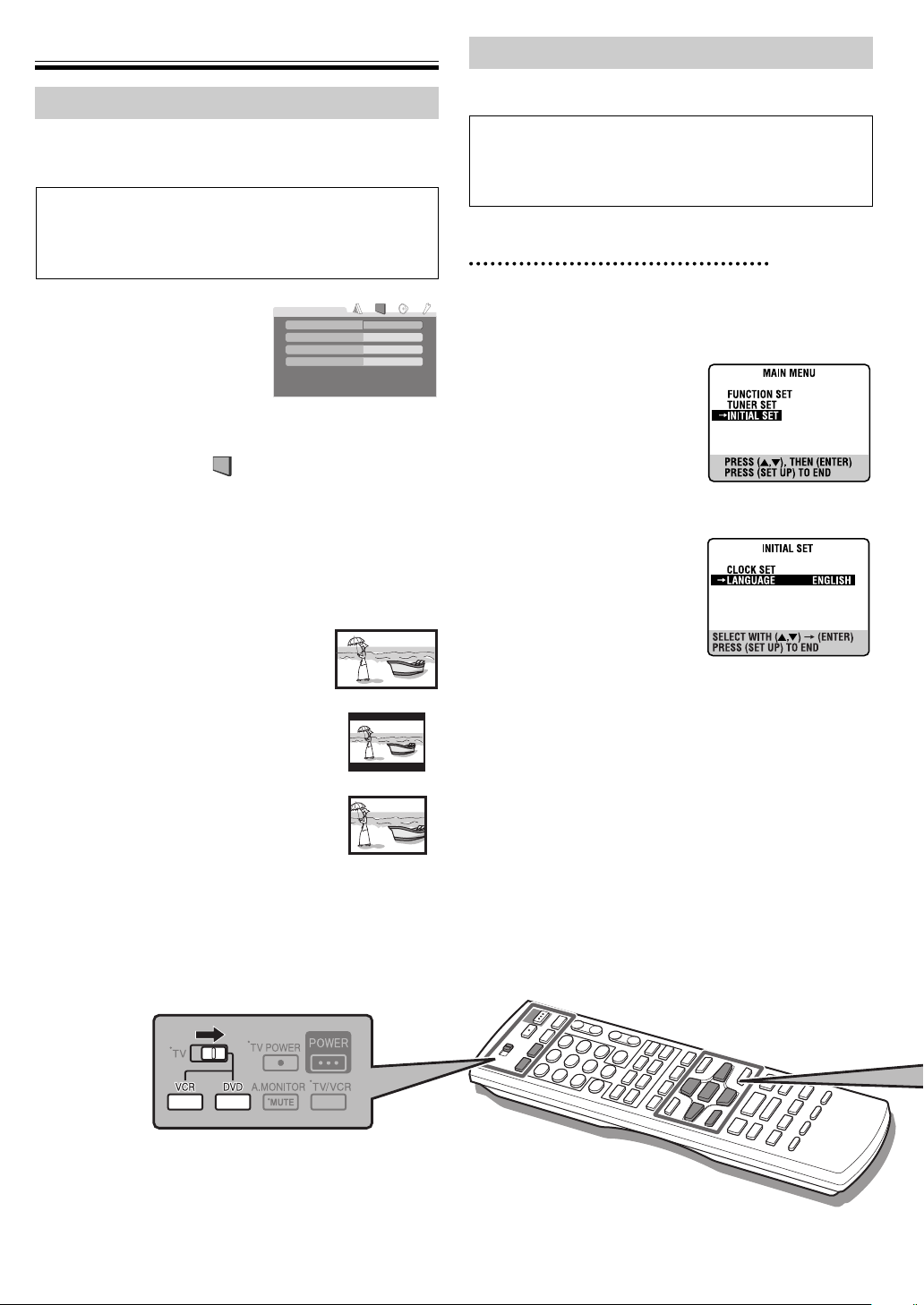
On-screen Language Set (VCR deck)
~ Select the VCR deck.
Press VCR on the Remote so that the VHS indicator
lights up on the front display panel.
Ÿ Access the Main Menu
screen, then select the
Initial Set.
1 Press SET UP to access
the Main Menu screen.
2 Press %fi to move the
highlight bar (arrow) to
“INITIAL SET,” then press ENTER.
! Select the language.
Press %fi to move the
highlight bar (arrow) to
“LANGUAGE,” then press
ENTER repeatedly until
the desired language is
selected.
⁄ Return to the normal screen.
Press SET UP.
@ Return to the normal screen.
Press SET UP.
12
Page 13

On-screen Language Set (DVD deck)
This DVD deck offers you the choice to view onscreen messages in 3 different languages.
~ Select the DVD deck.
Press DVD on the Remote so that the DVD indicator
lights up on the front display panel.
Ÿ Access the DVD Set
Up Menu screen.
1 Press SET UP.
LANGUAGE
MENU LANGUAGE
AUDIO LANGUAGE
SUBTITLE
ON SCREEN LANGUAGE
ENGLISH
ENGLISH
OFF
ENGLISH
2 Press @ # to select
“
LANGUAGE.”
! Select the mode.
Press %fi to move the
highlight to “ON SCREEN
LANGUAGE
MENU LANGUAGE
AUDIO LANGUAGE
SUBTITLE
ON SCREEN LANGUAGE
ENGLISH
ENGLISH
OFF
ENGLISH
LANGUAGE,” then press
ENTER.
⁄ Select the mode setting.
Press %fi to select the desired setting, then press
ENTER.
@ Return to the normal screen.
Press SET UP.
Menu/Audio/Subtitle Language Set
(DVD deck only)
Some DVD discs contain the DVD menu display,
audio, subtitle in the multiple language. With these
discs, you can set the default language.
~ Select the DVD deck.
Press DVD on the Remote so that the DVD indicator
lights up on the front display panel.
Ÿ Access the DVD Set
Up Menu screen.
1 Press SET UP.
LANGUAGE
MENU LANGUAGE
AUDIO LANGUAGE
SUBTITLE
ON SCREEN LANGUAGE
ENGLISH
ENGLISH
OFF
ENGLISH
2 Press @ # to select
“
LANGUAGE.”
! Select the mode.
Press %fi to move the
highlight to the mode you
LANGUAGE
MENU LANGUAGE
AUDIO LANGUAGE
SUBTITLE
ON SCREEN LANGUAGE
ENGLISH
ENGLISH
OFF
ENGLISH
want to change, then press
ENTER.
⁄ Select the mode setting.
Press %fi to select the desired setting, then press
ENTER.
• See “Language Code List.” (
pg. 38)
@ Return to the normal screen.
Press SET UP.
IntroductionPreparation
VCR Deck
Operations on
NOTE:
When the selected language is not available on the disc,
the disc’s default menu language is played back.
DVD Deck
Operations on
Advanced OperationsAdditional Information
13
Page 14

Initial Settings (continued)
Clock Set
Perform clock setting only if the clock has not been set
correctly by the Plug&Play setting.
• Turn on the TV and select the VCR channel (or AV
mode).
• Slide the TV/VCR/DVD switch on the Remote to the
right.
Preparations
~ Select the VCR deck.
Press VCR on the Remote so that the VHS indicator
lights up on the front display panel.
Ÿ Access the Main Menu screen.
Press SET UP.
! Access the Initial Set
screen.
Press %fi to move the
highlight bar (arrow) to
“INITIAL SET,” then press
ENTER.
⁄ Access the Clock Set
screen.
Press %fi to move the
highlight bar (arrow) to
“CLOCK SET,” then press
ENTER.
Manual Clock Set
~ Set the time, date, and
year.
Press %fi to set the hour, then
press ENTER.
Set the date and year in the
same way.
• Press and hold %fi to change
the time by 30 minutes or the date by 15 days.
Ÿ Select D.S.T. mode.
Press ENTER to move the
highlight bar to “D.S.T.,” then
press %fi to select the desired
setting.
ON: Adjustment will be made
by the built-in clock itself.
OFF: Select when Daylight Saving Time does not
apply to you.
! Start clock.
Press SET UP and normal screen appears.
To make corrections any time during the process
Press ENTER repeatedly until the item you want to
change blinks, then press %fi.
14
Semiauto Clock Set
You can change the host channel/D.S.T. (Daylight
Saving Time)/time zone setting manually.
NOTE:
The time set previously will be erased when “AUTO CLOCK,”
“HOST CH,” “D.S.T.,” or “TIME ZONE” setting is changed.
~ Set “AUTO CLOCK” to
“ON.”
Press ENTER repeatedly to
move the highlight bar to “AUTO
CLOCK,” then press %fi so that
“ON” is selected.
Ÿ Select the host channel.
You can either select “AUTO” or enter a PBS channel
number.
Press ENTER to move the highlight bar to “HOST CH,”
then press %fi repeatedly until “AUTO” or the desired
PBS channel number is selected.
NOTE:
Some PBS channels do not transmit clock setting data.
! Select the D.S.T. mode.
Press ENTER to move the highlight bar to “D.S.T.,”
then press %fi repeatedly until the desired setting is
selected.
AUTO: Select if you want to adjust your VCR’s clock
automatically by the incoming signal from the
host channel. Be sure to select the correct
time zone manually in step ⁄.
ON: Adjustment will be made by the built-in clock
itself.
OFF: Select when Daylight Saving Time does not
apply to you.
⁄ Select the time zone.
Press ENTER to move the highlight bar to “TIME
ZONE,” then press %fi repeatedly until “AUTO” or the
desired time zone is selected. Each time you press the
button, the time zone changes as follows:
O AUTO O ATLANTIC O EASTERN O CENTRAL
O MOUNTAIN O PACIFIC O ALASKA O HAWAII O
(back to the beginning)
@ Complete the Semiauto Clock Set.
Press SET UP to return to normal screen.
IMPORTANT
Turn off the unit after performing Semiauto Clock.
“Auto” will appear on the front display panel while the
clock is being set. The current clock time will appear
automatically when the clock setting is complete.
Page 15

Tuner Set
• Turn on the TV and select the VCR channel (or
AV mode).
• Slide the TV/VCR/DVD switch on the Remote to
the right.
Auto Channel Set
Perform Auto Channel Set only if channels have not
been set correctly by the Plug&Play setting.
~ Select the VCR deck.
Press VCR on the Remote so that the VHS indicator
lights up on the front display panel.
Ÿ Access the Main Menu
screen, then select the
Tuner Set.
1 Press SET UP.
2 Press %fi to move the
highlight bar (arrow) to
“TUNER SET,” then
press ENTER.
! Perform Auto Channel
Set.
Press %fi to move the
highlight bar (arrow) to
“AUTO CHANNEL SET,”
then press ENTER. You
can automatically set the
receivable channels in your
area in the order of their
frequencies.
• When Auto Channel Set is
complete, “SCAN
COMPLETED” appears on
the TV screen.
• If the scan was unsuccessful, “SCAN
COMPLETED-NO SIGNAL-” appears on screen.
Check the connections and start again.
⁄ Return to the normal screen.
Press SET UP.
Manual Channel Set
You can add the channels you want or delete the
channels you do not want manually.
~ Select the VCR deck.
Press VCR on the Remote so that the VHS indicator
lights up on the front display panel.
Ÿ Access the Main Menu screen, then select the
Tuner Set.
1 Press SET UP.
2 Press %fi to move the highlight bar (arrow) to
“TUNER SET,” then press ENTER.
! Access the Manual
Channel Set screen.
Press %fi to move the
highlight bar (arrow) to
“MANUAL CHANNEL SET,”
then press ENTER.
⁄ Add or skip the desired
channels.
To add channels
1 Press the number
keys to input a channel
number you want to add.
2 Press ENTER to set to
“ADD.”
3 Repeat 1 to 2 to add other channels.
To skip channels
1 Press %fi or the number buttons to select a
channel number you want to skip.
2 Press ENTER to set to “SKIP.”
3 Repeat 1 to 2 to skip other channels.
@ Return to the normal screen.
Press SET UP.
IntroductionPreparation
VCR Deck
Operations on
DVD Deck
Operations on
Advanced OperationsAdditional Information
15
Page 16

Playback on VCR Deck
Basic Playback
• Turn on the TV and select the VCR channel (or AV
mode).
• Slide the TV/VCR/DVD switch on the Remote to the
right.
Variable Speed Search (including slow-motion)
Press 1 REW or FF ¡ repeatedly.
• Press 3 PLAY to resume normal playback.
• Each time you press 1 REW or FF ¡, the playback speed
changes. To decrease the speed during picture search, press
the opposite direction button repeatedly.
Reverse Forward
Reverse search
3 steps
Slow
motion
Normal
play
Forward search
2 steps
~ Load a cassette.
Make sure the window
side is up, the rear label
side is facing you and the
arrow on the front of the cassette is pointing towards the
recorder.
• Do not apply too much pressure when inserting.
• The unit turns on, and the counter is reset
automatically.
• If the cassette’s record safety tab has been removed,
playback begins automatically.
Ÿ Select the VCR deck.
Press VCR on the Remote so that the VHS indicator
lights up on the front display panel.
! Start playback.
Press 3 PLAY.
During playback
Stop playback
Press 7 STOP on the Remote.
Pause playback and view still picture
Press 8 PAUSE.
• Press 3 PLAY to resume normal playback.
• If there is vertical jitter, press CH + or – to correct the
picture.
Pause and Frame-by-Frame playback
Press 8 PAUSE to pause, then press 8 PAUSE
repeatedly.
• Press 3 PLAY to resume normal playback.
• During still picture, holding 8 PAUSE for more than 2
seconds starts forward slow motion playback.
If you press 8 PAUSE again, still picture resumes.
• During slow motion playback, some noise may appear on the
TV screen. Press CH + or – to eliminate the noise.
When the tape is not running
Rewind/fast-forward at high speed
Press 1 REW or FF ¡.
Eject the cassette
Press 0 EJECT on the unit.
• You can also eject the cassette when the recorder is
turned off.
Turn off the unit
Press POWER.
NOTE:
In the search, still, slow-motion or frame-by-frame playback
mode,
• the picture will be distorted
• the noise bars will appear
• there will be a loss of color with an LP-recorded tape
16
Page 17

On-Screen Display (VCR deck)
If you press ON SCREEN on the Remote when “SUPERIMPOSE” is set to “ON” (☞ pg. 32), various operational
indicators appear on the TV screen.
Press ON SCREEN again to clear the display.
1
2
3
4
5
6
1
Channel Position Number/Auxiliary Input Indicator
(F-1)
2 Day/Clock Display
3 Stereo Program Indicator
4 SAP Indicator
5 Tape Position Indicator
The position of “
or “E” (end) shows the current position on the
tape.
” in relation to “B” (beginning)
7
8
9
p
q
w
6 Audio Mode Display
7 Opening Mode Indicators
8 Tape Speed (SP/EP)
9 “Cassette Loaded” Mark
p Index number
q Tape Remaining Time Indicator
w Counter Display
VCR Deck
Operations on
DVD Deck
Operations on
Advanced OperationsAdditional Information IntroductionPreparation
17
Page 18

Playback on VCR Deck (continued)
Playback Features
Skip Search
During playback, press (Skip Search) 1 to 6 times to
skip over unwanted sections.
Each press initiates a 30-second period of fast-motion
playback. Normal playback resumes automatically.
• To resume normal playback during a Skip Search,
press 3 PLAY.
Index Search
Index codes are placed on the
tape at the beginning of each
recording when recording on
this unit.
1 While the tape is not
running, press 4 INDEX
or INDEX ¢ to start search.
2 To access a recording of 2 to 9 index codes away,
press 4 INDEX or INDEX ¢ repeatedly until the
correct number is displayed.
Example:
To locate the beginning
of B from the current
position, press 4
INDEX twice.
To locate the beginning
of D from the current
position, press INDEX
¢ once.
• Playback begins automatically when the desired
recording is located.
Current position
Index number
Instant ReView
Simply by pressing a single button, the unit power
comes on, rewinds, and begins playback of the last
timer-recorded program. If you have several programs
recorded, you can easily access any of them.
NOTE:
Before starting, make sure that the unit is off and that the
Timer mode is disengaged.
Activate Instant ReView
Press
the unit searches for the index code indicating the
start of the last timer-recorded program. Once it’s
found, playback begins automatically.
• To watch the fi rst of the 3 programs, press
three times. The unit searches and begins playback
automatically. You can access a program as far as 9
index codes away from the current tape position.
(4). The unit power comes on and
Next Function Memory
The Next Function Memory “tells” the unit what to do
after rewinding. Ensure that the unit is in stop mode.
• Automatic Playback Start
Press 1 REW, then press 3 PLAY within 2
seconds.
• Automatic Power Off
Press 1 REW, then press POWER within 2
seconds.
• Automatic Timer Standby
Press 1 REW, then press TIMER within 2
seconds.
• Automatic Cassette Ejection After Tape Rewind
Press 1 REW, then press 0 EJECT within 2
seconds.
18
Page 19

Repeat Playback
During playback, press and hold 3 PLAY for more
than 5 seconds. “3” on the front display panel starts
blinking slowly. To stop playback, press 7 STOP.
NOTE:
Pressing 3 PLAY, 1 REW, FF ¡ or 8 PAUSE also
stops Repeat Playback.
One Touch Replay
Press (One Touch Replay) during playback.
Pressing
to about 7 seconds before the current position. You
can press
once moves the playback position back
up to 4 times each One Touch Replay.
Selecting Soundtrack
Your recorder is capable of recording three
soundtracks (HIFI L, HIFI R and NORM) and plays
back the one you select.
Pressing A.MONITOR changes the soundtrack as
follows:
H I-F I: Hi-Fi sound is played back
H I-F I L: Sound on the left Hi-Fi channel is played
back
H I-F I R: Sound on the right Hi-Fi channel is played
back
NORM: Sound on the normal track is played back
NORM Both sounds on the Hi-Fi track and normal
H I-F I: track are mixed and played back
Adjusting Tracking Condition
Automatic tracking adjustment
When a new cassette is loaded, the recorder enters
the automatic tracking mode.
Manual tracking adjustment
If automatic tracking cannot eliminate noises well
during playback, adjust the tracking manually.
1 Press TRACKING +/– at the same time during
playback to activate manual tracking.
2 Press TRACKING to eliminate the noises. Press
it briefly for a fine adjustment, or press and hold
for a coarse adjustment.
3 Press TRACKING +/– again to reactivate
automatic tracking.
NOTE:
Set “SUPERIMPOSE” to “ON” to display the indications on
the screen.(☞ pg. 32)
VCR Deck
Operations on
DVD Deck
Operations on
Advanced OperationsAdditional Information IntroductionPreparation
19
Page 20

Recording
Recording Features
Basic Recording
• Turn on the TV and select the VCR channel (or AV
mode).
• Slide the TV/VCR/DVD switch on the Remote to the
right.
~ Load a cassette.
Make sure the record safety tab is intact. If not, cover
the hole with adhesive tape before inserting the
cassette.
• The recorder turns on, and the counter is reset,
automatically.
Ÿ Select the VCR deck.
Press VCR on the Remote so that the VHS indicator
lights up on the front display panel.
! Select recording channel.
Press CH +/– or the number buttons.
• You can select channel in the stop mode or recording
pause mode.
⁄ Set tape speed.
Press SP/EP. The current setting for the tape speed
appears on the display panel and the screen for about
5 seconds. Press SP/EP again to change the setting
while tape speed is displayed.
@ Start recording.
On the recorder, press ¶ REC. Or on the Remote, while
holding ¶ REC, press 3 PLAY.
• If the tape reaches its end during recording, the
recording stops and “¶” and “3” on the display panel
blink.
During recording
Pause recording
Press 8 PAUSE.
• Press 3 PLAY to resume recording.
• You can select channel in the recording pause mode.
Stop recording
Press 7 STOP on the Remote.
Watching one programme while recording
another
If your recorder is connected to the TV via the AV
connection, press TV/VCR. The recorder’s VCR
indicator and the TV broadcast being recorded
disappear. Once recording is in progress, all you need
to do is to set the channel controls on the TV for the
station you wish to view.
• The programme selected with the TV’s channel
controls appears on the screen, while the one selected
with the CH +/– is recorded on the tape.
Instant Timer Recording (ITR)
During recording, press ¶ REC on the unit repeatedly
until the desired recording length appears on the display
panel. “¶” on the display panel starts blinking.
• Each time you press the button, recording length
increases in 30-minute intervals (up to 6 hours).
• The unit turns off after recording is fi nished.
Tape Remaining Time/Time Counter
Press DISPLAY repeatedly to display the tape
remaining time and time counter on the front display
panel. To reset the time counter, press C.RESET.
NOTE:
Depending on the type of tape being used, the tape remaining
time reading may not appear right away, or is not correct.
“– –:– –” may sometimes appear with “:” blinking, or the
display may blink on occasion.
Second Audio Recording
This unit’s built-in MTS decoder enables reception of
Multichannel TV Sound broadcast. To record a SAP
program received, set “2ND AUDIO RECORD” to “ON.”
(☞ pg. 33)
Accidental erasure prevention
To prevent accidental recording
on a recorded cassette, remove
its record safety tab. To record
on it later, cover the hole with
adhesive tape.
Record safety tab
20
Page 21

Timer Recording
Express Timer Programming
Select the VCR deck.
~
Press VCR on the Remote so that the VHS indicator
lights up on the front display panel.
Ÿ Access the Program
screen.
Press PROG. (If you’re just
starting out, “PROGRAM 1”
appears.)
! Enter the program
start time.
Press START +/– to enter
the time you want recording
to start.
• Press and hold START
+/– to move in 30-minute
increments, or press and release repeatedly to
move 1 minute at a time.
⁄ Enter the program stop time.
Press STOP +/– to enter the time you want recording
to stop.
• Press and hold STOP +/– to move in 30-minute
increments, or press and release repeatedly to
move 1 minute at a time.
@ Enter the program date.
Press DATE +/–.
• The current date appears on the TV screen. The
date you enter appears in its place.
¤ Enter the channel position.
Press CH +/–.
# Set the tape speed.
Press SP/EP.
‹ Return to the normal screen.
Press PROG or ENTER. “PROGRAM COMPLETED”
appears on the TV screen for about 5 seconds, then
the normal screen appears. If “PROGRAM NOT
COMPLETED PROGRAM OVERLAP” appears on
the TV screen, see page 22.
• Repeat step Ÿ to ‹ for each additional program.
$ Engage the unit’s timer mode.
Press TIMER. The unit turns off automatically and
“
” appears on the front display panel.
• To disengage the timer mode, press TIMER again.
To Timer-Record Weekly Or Daily Serials:
— anytime during steps ! through #, press
WEEKLY (number button “9”) for weekly serials
or DAILY (number button “8”) for daily serials
(Monday – Friday). Either “WEEKLY” or “DAILY”
appears on the TV screen. Pressing the button again
makes the corresponding indication disappear.
NOTES:
• You can program this unit to timer-record as many as 8
programs. If you try to program the unit to record a ninth,
“PROGRAM FULL” appears on the TV screen. To record
the extra program, you must fi rst cancel any unnecessary
programs. (☞ pg. 22)
• Programs that start after midnight must have the next
day’s date.
Cable Box or DBS Receiver Users
To timer-record a satellite broadcast using Express
Timer Programing:
1 Perform steps ~ – $. Enter “F-1” for the
channel position in step ¤.
2 Set the DBS receiver to the appropriate
channel before the selected program begins.
3 Leave the DBS receiver’s power on.
VCR Deck
Operations on
DVD Deck
Operations on
Advanced OperationsAdditional Information IntroductionPreparation
21
Page 22

Timer Recording (continued)
Check, cancel and change programs
~ Disengage the timer mode.
Press TIMER, then press POWER.
Ÿ Access the Program
Check screen.
Press PROG. CHECK.
When programs overlap each other
If “PROGRAM NOT COMPLETED PROGRAM
OVERLAP” appears, you have another program
overlapping the program you have just made.
The Program Check screen appears and conflicting
programs will start blinking.
! Access the Program
screen.
Press PROG. CHECK again to
check more information.
Each time you press PROG.
CHECK, the next program’s
information appears.
To cancel or change a program
⁄ Cancel or change a program.
Press CANCEL to cancel a program. To change
program settings, press the appropriate button: START
+/–, STOP +/–, DATE +/–, CH +/–, DAILY (number
button “8”), WEEKLY (number button “9”) and/or
SP/EP.
@ Return to the normal screen.
Press PROG. CHECK as many times as necessary.
If there are still some programs remaining, go on to
step ¤.
¤ Return to the timer mode.
Press TIMER.
Example: Program 1 (you have just made) and
Program 4 overlap each other.
~ Confirm the overlapping programs.
Overlapping programs blink on the TV screen.
Ÿ Select the program to modify.
Press %fi, then press ENTER.
• You can only select one of the overlapping programs.
NOTE:
If you do not mind this overlap, press PROG to finish the timer
program setting. The program with the lower program number
will be recorded and the other one will not be recorded
correctly. If no changes are made for approximately 1 minute,
the unit will return to the normal screen.
! Cancel or change program setting.
To cancel a program, press CANCEL when the
Program screen you do not want is shown. “PROGRAM
COMPLETED” appears on the TV screen for about 5
seconds, then the normal screen appears.
To change a program, press the appropriate button:
START +/–, STOP +/–, DATE +/–, CH +/–, DAILY
(number button “8”), WEEKLY (number button “9”)
and/or SP/EP when the Program screen on which you
want to make changes is shown, then press ENTER.
“PROGRAM COMPLETED” appears on the TV screen
for about 5 seconds, then the normal screen appears.
22
NOTE:
If the overlap is not yet solved, or another overlap occurs with
the timer program setting after making the last correction on
a program, the conflicting programs will be shown on the
Program Check screen again. Repeat the above steps again
until the overlap is solved.
Page 23

Satellite Auto Recording
This function allows you to automatically record a
satellite program which is timer-programed on your
external DBS receiver or the cable box if it has a
timer.
ATTENTION
Be sure not to turn on the DBS receiver before
the program is executed; otherwise, the unit will
start recording when the DBS receiver’s power is
turned on.
Before performing the following steps:
• Make sure the DBS receiver is connected to the
unit’s VIDEO/AUDIO input (F-1) connector.
• Program the timer on the DBS receiver.
• Insert a cassette with the safety tab in place.
• Turn on the TV and select the VCR channel (or
AV mode).
• Slide the TV/VCR/DVD switch on the Remote to
the right.
~ Select the VCR deck.
Press VCR on the Remote so that the VHS indicator
lights up on the front display panel.
Ÿ Set the tape speed.
Press SP/EP.
! Engage the Satellite Auto Recording mode.
Press and hold REC LINK for about 2 seconds. The
“
” and “ ” indicators light up and the unit turns off
automatically.
NOTES:
• Operation on the DVD deck are not possible when
the Automatic Satellite Program Recording mode is
engaged, or timer recording is in progress.
• To disengage the Satellite Auto Recording mode, press
REC LINK. The “ ” indicator goes off.
• Depending on the type of DBS receiver, the unit may not
record a slight portion of the beginning of the program or
may record slightly longer than the actual length of the
program.
VCR Deck
Operations on
DVD Deck
Operations on
Advanced OperationsAdditional Information IntroductionPreparation
23
Page 24

Playback on DVD Deck
Basic Playback
• Turn on the TV and select the VCR channel (or AV
mode).
• Slide the TV/VCR/DVD switch on the Remote to the
right.
~ Load a disc.
1 Press 0 OPEN/CLOSE on
the unit to open the disc tray.
2 Place the disc in the disc tray
with the label side up.
• To insert an 8-cm disc,
place it the inner recess.
3 Press 0 OPEN/CLOSE to close the disc tray.
• Some DVDs start playback automatically.
Ÿ Select the DVD deck.
Press DVD on the Remote so that the DVD indicator
lights up on the front display panel.
! Start playback.
Press 3 PLAY.
During playback
Playback Features
Using the disc menu
You can operate a disc—SVCD/VCD with Playback
Control* (PBC)—using the disc menu shown on the TV
screen.
* A method of controlling disc play for SVCD/VCD by
using the disc menu.
7 For DVD
1 Press TOP MENU or MENU to show the disc menu.
2 Press %fi@# to select a desired item, then press
ENTER or 3 PLAY.
• With some discs, you can also select items by entering
the number using the number buttons.
7 For SVCD/VCD
1 While stopped, press TOP MENU or 3 PLAY to
show the menu.
2 Press the numeric buttons to select a desired item.
• To move to the next or previous page of the current
menu, press SKIP ¢ or 4 SKIP.
• To return to the previous menu, press RETURN.
To play back without PBC
While stopped, press the numeric buttons instead of 3
PLAY to start playback.
To reactivate PBC
• Press TOP MENU or MENU.
• Press 7 STOP to stop playback, then 3 PLAY.
Stop playback
Press 7 STOP on the Remote.
• When “RESUME” is set to “ON” (☞ pg. 35), the unit
memorizes the position on the disc where you have
interrupted playback.
– To resume playback, press 3 PLAY.
– To stop playback completely, press 7 STOP again.
Pause and Frame-by-Frame playback
Press 8 PAUSE. Each time you press the button, the still
picture advances to the next frame.
• Press 3 PLAY to resume normal playback.
Skip chapter or track
Press SKIP ¢ or 4 SKIP.
Variable Speed Search
Press FF ¡ or 1 REW. Each time you press the button, the
playback speed changes.
• If you press and hold SKIP ¢ or 4 SKIP, the playback is
advanced/reversed at 5 times normal speed.
Slow Motion playback
Press FF ¡ or 1 REW while playback is paused. Each time
you press the button, the playback speed changes.
• Press 3 PLAY to resume normal playback.
• Reverse slow motion is available only for DVD VIDEO discs.
Zooming the picture
1 Press ZOOM.
2 Each time you press ZOOM, the magnification
changes.
• You can use %fi@# button to move the zoomed
position.
3 To return to the normal playback, select the normal
size by pressing ZOOM repeatedly.
One Touch Replay
Press while playing back a DVD VIDEO disc.
The playback position moves back about 10 seconds
before the current position (only within the same title).
24
Page 25

Changing the language, sound,
and scene angle
1 Press the corresponding button.
SUBTITLE:
select audio language for DVD VIDEO.
A.MONITOR:
select audio language for DVD VIDEO.
select audio channel for SVCD/VCD.
ANGLE:
select the view-angle.
2 Press %fi to select the desired setting, then
press ENTER.
Repeat Playback
Press REPEAT repeatedly to select the desired
repeat mode.
DVD VIDEO (during playback)
CHAP: The current chapter is played back
repeatedly.
TITLE: The current title is played back repeatedly.
OFF: Each title and chapter is played back once.
Video CD/SVCD/Audio CD
(in stop mode or during playback with PBC
deactivated)
TRACK: The current track is played back repeatedly.
ALL: All tracks are played back repeatedly.
OFF: Each track is played back once.
Changing the Sound Field
This function makes a human voice clearer.
1 Press SOUND EFFECT.
2 Each time you press SOUND EFFECT, the
Sound Effect mode changes.
• As the value becomes bigger, the Sound Effect
works stronger.
NOTE:
The Sound Effect function works correctly only for a DVD
VIDEO disc recorded in the 5.1-channel audio format.
Changing the picture tone (VFP)
The VFP (Video Fine Processor) function allows
you to adjust the picture character according to
the type of programming, picture tone or personal
preferences.
1 Press DVD PICTURE.
2 Press @# to select the desired preset.
NORMAL For watching TV in a general room.
CINEMA For watching a movie software in a
USER1
USER2
To adjust the picture tone
1 Select “USER1” or “USER2.”
2 Press %fi to select a parameter, then press
ENTER.
GAMMA Adjust this if the neutral color is bright or
BRIGHTNESS Adjust this if the picture is bright or
CONTRAST Adjust this if the far and near position is
SATURATION Adjust this if the picture is whitish or
TINT Adjust this if the appearance of fl esh
SHARPNESS Adjust this if the picture is indistinct (–8
3 Press %fi to adjust the parameter, then press
ENTER.
4 Repeat step 2 and 3 to adjust other
parameters.
5 Press DVD PICTURE to finish the setting.
room with suppressed light.
You can adjust parameters that affect
the picture character and store the
settings as a user preset. See below.
dark. The brightness of dark and bright
portion is maintained (–3 to +3).
dark on the whole (–8 (darkest) to +8
(brightest)).
unnatural (–7 to +7).
blackish (–7 (blackest) to +7 (whitest)).
tone is unnatural (–7 to +7).
to +8).
IntroductionPreparation
VCR Deck
Operations on
DVD Deck
Operations on
Advanced OperationsAdditional Information
25
Page 26

Playback on DVD Deck (continued)
Menu Bar Functions
You can use various functions from the menu bar.
To Bring Up the Menu Bar
When a disc is inserted, press ON SCREEN twice.
A menu bar for the type of disc inserted will appear
under the status bar.
Ex.: Menu bar for DVD VIDEO
Transfer
rate
To dismiss the menu bar and the status bar, press ON
SCREEN.
Title
number
Chapter
number
Playback
status
Playback time
Basic Operation Procedure
~ Press @# to select the icon you want to work
with.
Ÿ Press ENTER.
After pressing ENTER:
1 When a pull-down menu appears, press %fi to
select the setting you want, then press ENTER.
2 When a number-entry box appears, use the
number buttons to enter the number you want,
then press ENTER.
3 When changing
repeatedly to select the setting you want.
NOTES:
• The selected item on the menu bar is shown in green.
• The available functions differ depending on the player status.
Refer to the explanation below to check when you can use a
certain function.
setting, press ENTER
Menu Bar Functions
selects the time mode shown in the display
window and the status bar.
• TOTAL: Elapsed time of current title (DVD) or a disc
(CD/VCD/SVCD)
• T.REM: Remaining time of current title (DVD) or a disc
(CD/VCD/SVCD)
(Except for DVD: while stopped, disc total time)
• TIME: Elapsed time of current chapter (DVD) or track
(CD/VCD/SVCD)
• REM: Remaining time of current chapter (DVD) or track
(CD/VCD/SVCD)
(while stopped, current track total time)
selects repeat mode.
DVD: During playback
CD: In any condition
VCD/SVCD: In any condition except PBC playback
• CHAPTER: Current chapter repeat (DVD)
• TITLE: Current title repeat (DVD)
• TRACK: Current track repeat (CD/VCD/SVCD)
• ALL: All track repeat (CD/VCD/SVCD)
• A-B: A-B repeat (During playback). After
selecting A-B, press ENTER at the
beginning point of repeat, then press
ENTER again at the end point.
• OFF: Repeat mode deactivated. Select this to
quit repeat mode.
specifi es beginning point of a title (DVD) or a disc
(CD/VCD/SVCD) by the time.
DVD: In any condition
CD: In any condition except program or random
playback
VCD/SVCD: In any condition except PBC or program or
random playback
specifies a chapter to play back from (DVD only).
selects the audio language (DVD), sound track
(DVD), or audio channel (VCD/SVCD) during playback.
(SVCD) during playback.
selects the subtitle language (DVD) or subtitle
26
selects a scene angle in a multiangle part (DVD only).
Page 27

MP3/JPEG Files Playback
You can play back MP3/JPEG files on a CD/CDR/RW.
Precautions
• Use “ISO 9660” as the disc format.
• The unit does not support “packet writing (UDF format)”
discs.
• The unit supports discs recorded with up to fi ve multiple
sessions.
• The unit may be unable to play back a disc due to the
characteristics or recording conditions.
•
The unit recognizes up to 99 groups, 150 fi les per group.
If a disc includes more than the fi les above limit, the unit
stops detecting fi les when the number of detected fi les
reaches the limit and ignores the subsequent fi les. The unit
also ignores any non-MP3/JPEG fi le in the disc.
• Add the appropriate extension (“.mp3” and “.jpg”) to the fi le
name.
• MP3i and MP3 Pro are not available.
• This unit supports the JPEG fi les whose resolution is 32 to
8192 pixel in width and 32 to 7680 pixel in height.
• We recommend to record a fi le at 640 x 480 resolution. (If
a fi le has been recorded at a resolution of more than 640 x
480, it will take a longer time to be displayed.)
Control Display
The control display appears on the TV screen when
an MP3 or a JPEG disc is loaded.
Example: When an MP3 disc is loaded
Total group number on
Current group
number
Current group
* For MP3 only
Elapsed playing time of current track is only shown
during playback.
Press %fi@# to move the cursor bar to a desired
file, then press 3 PLAY.
• For JPEG fi les: when you press ENTER, only the
selected fi le is played back.
Current file
disc
number
Current file Total file number on
Total file number in
*
current group
disc
Group/File Selection
To start playback by specifying the group/file
number
1 Press the number buttons to enter the group
number.
2 Press the number buttons to enter the file
number.
Example:
To select 3: Press 3.
To select 14: Press +10, then 4.
To select 20: Press +10, then 10.
Or press +10 twice, then 0.
To select 24: Press +10, +10, then 4.
To select 110: Press +10 ten times, then 10.
For MP3 files playback
Playback starts from the file you have specified.
For JPEG files playback
• The slide-show playback starts from the fi le you
have specified.
• To display only the selected fi le, then press ENTER.
To start slide-show playback from that file, press
ENTER again.
Repeat Playback
You can repeat playback of the current group, file
(only for MP3 files), or all groups.
• While the control display is on the TV screen:
~ Select the mode.
Press REPEAT to select the desired repeat mode.
• Each time you press REPEAT, the mode changes
as follows:
For MP3 files playback
TRACK: The current file (track) is
played back repeatedly.
GROUP: All files of the current group are
played back repeatedly.
ALL: All files are played back
repeatedly.
OFF (No indication): Each file is played back once.
For JPEG files playback
GROUP: All files of the current group are
played back repeatedly.
ALL: All files are played back
repeatedly.
OFF (No indication): Each file is played back once.
Ÿ Start playback.
Press 3 PLAY.
Zooming a still picture
Press ZOOM while playing back a JPEG file.
• Each press of ZOOM changes the magnifi cation.
• To resume normal playback, press ENTER.
IntroductionPreparation
VCR Deck
Operations on
DVD Deck
Operations on
Advanced OperationsAdditional Information
27
Page 28

Editing
Editing with another video recorder or a camcorder
You can use your recorder as the source player or the
recording deck. You can use a camcorder as the source
player and your recorder as the recording deck. Refer
also to the other components’ instruction manuals for
connection and its operations.
When using the unit as the source player
TV
Source player
To AV input
Audio/video
cable
Recorder
When using the unit as the recorder
Your unit
Audio/video
cable
To AV inputTo AV output
Another recorder
~ Make connections.
Connection with another video recorder
1 When using your unit as the source player ...
... connect its AUDIO/VIDEO OUTPUT connectors on
the rear panel to the recording deck.
2 When using your unit as the recording deck ...
... connect its VIDEO/AUDIO connectors on the front
panel to the source player.
Connection with a camcorder
Connect the camcorder’s AUDIO/VIDEO OUT
connectors to the unit’s VIDEO/AUDIO connectors on
the front panel via a cable adapter.
Ÿ Select the VCR deck.
Press VCR on the Remote so that the VHS indicator
lights up on the front display panel.
! Load cassettes.
Insert the playback cassette into the source player and
the cassette to be recorded on into the recording deck.
⁄ Select input mode on recording deck.
Select the correct external input on the recording deck.
On this recorder, press AUX (number button “0”) and/or
CH +/– to select “F-1.”
@ Select edit mode.
See “PICTURE CONTROL” on page 32.
¤ Set the recorder to the record pause mode.
Locate the point where you start recording on the
source player, then operate the recorder so that
recording is paused.
# Start playback on the source player.
Audio/video
cable
To AV input
Recorder
To AV output
Another recorder
Source player
‹ Start recording on the recorder.
Your unit
Audio/video
cable
28
Page 29

Dubbing from DVD to VCR
• Turn on the TV and select the VCR channel (or
AV mode).
• Slide the TV/VCR/DVD switch on the Remote to
the right.
~ Load a cassette and place a disc.
Ÿ Prepare the VCR deck for dubbing.
1 Press VCR.
2 Press SP/EP to select recording speed.
3 Search for the point where you want to start
dubbing.
! Prepare the DVD deck for dubbing.
1 Press DVD.
2 Search for the point where you want to start
dubbing.
3 Press 8 PAUSE to pause playback.
⁄ Start dubbing.
Press and hold ¶ REC, then press 3 PLAY on the
Remote.
• “
(dub)” lights on the front display panel.
@ End dubbing.
Press 7 STOP.
• Be sure to press 7 STOP while the VCR indicator
lights up on
NOTES:
• It is not possible to dub the copy-protected disc.
• Set “ON SCREEN GUIDE” to “OFF” (☞ pg. 35) if you do
not want to record the on-screen display for DVD discs
during dubbing.
the unit.
IntroductionPreparationAdvanced Operations
VCR Deck
Operations on
DVD Deck
Operations on
Additional Information
29
Page 30

System Connections
Connecting To A Dolby Digital Decoder or
An Amplifier With A Built-in DTS
(DVD deck only)
Dolby digital
decoder or amplifier
with a built-in DTS
To Digital audio
input
Coaxial digital audio cable
(not supplied)
These instructions enable you to connect your unit to
dolby digital decoder or amplifier with a built-in DTS.
Connect the coaxial cable between the unit and the
Dolby Digital decoder or amplifier with a built-in DTS.
NOTES:
• For Dolby digital sound, set “DIGITAL AUDIO OUTPUT” to
“DOLBY DIGITAL/PCM.” (☞ pg. 35)
• For DTS sound, set “DIGITAL AUDIO OUTPUT” to “STREAM/
PCM.” (☞ pg. 35)
Your unit
DIGITAL AUDIO OUT
30
Page 31

Other Functions
Slide the TV/VCR/DVD switch on the Remote to
the right.
Remote A/B/C/D Code Switching
The Remote is capable of controlling four JVC video
units independently. Each of units can respond to
one of four codes (A, B, C or D). The preset code is
A.
On the Remote
Keep pressing VCR down during steps ~ - Ÿ.
~ Change the Remote code.
Press the number button “1” for A, “2” for B, “3” for
C or “4” for D.
Ÿ Set the Remote code.
Press ENTER to set the code.
NOTE:
Once the batteries are removed, the Remote code is back
to A.
On the unit
~ Turn off the unit.
Press POWER on the unit.
Ÿ Display the code.
Press 3 PLAY on the unit for over 5 seconds while
the unit is turned off. The code currently set appears
on the front display panel.
! Change the unit’s code.
Press 7 STOP on the unit. The code currently set on
the Remote will be applied to the unit.
NOTE:
Even if you unplug the end of the mains power cord from
the mains, the code currently set remains.
Child Lock
You can disable the unit’s operation.
~ Set the Child Lock.
Press and hold POWER on the Remote for more
than 10 seconds while the unit is turned on. The unit
turns off, and “
panel.
• To release the child lock, press and hold POWER
on the Remote until the unit turns on.
NOTE:
Timer recording programs will be performed even if the
child lock function is activated.
Tray Lock
You can lock the disc tray to prohibit the unwanted
disc ejection by children.
To lock the disc tray
While the unit is turned off, press and hold 7 STOP,
then press 0 OPEN/CLOSE on the unit.
“
(Lock)” appears on the front display panel and
the disc tray is locked.
To unlock tray
While the unit is turned off, press and hold 7 STOP,
then press 0 OPEN/CLOSE on the unit.
“
panel.
(Unlock)” appears on the front display
(CL)” appears on the front display
IntroductionPreparationAdvanced Operations
VCR Deck
Operations on
DVD Deck
Operations on
Additional Information
31
Page 32

Subsidiary Settings
Mode Set (VCR deck)
• Turn on the TV and select the VCR channel (or AV mode).
• Slide the TV/VCR/DVD switch on the Remote to the right.
You can change various mode settings on the Function Set screen.
~ Select the VCR deck.
Press VCR on the Remote so that the VHS indicator
lights up on the front display panel.
Ÿ Access the Main Menu
screen, then select the
Function Set.
1 Press SET UP to access
the Main Menu screen.
2 Press %fi to move the
highlight bar (arrow) to
“FUNCTION SET,” then press ENTER.
* The default setting is bold in the table below.
PICTURE CONTROL
NORM
EDIT
SOFT
SHARP
SUPERIMPOSE
ON
OFF
AUTO SP =EP TIMER
ON
OFF
This feature helps you to adjust the playback picture quality according to your preference. Normally
select “NORM.”
NORM: Picture quality is adjusted automatically.
EDIT: Minimizes picture degradation during editing (recording and playback).
SOFT: Reduces image coarseness when viewing overplayed tapes containing a lot of noise.
SHARP: Clearer, sharper-edged picture when viewing images with lots of flat, same-colored surfaces
such as cartoons.
NOTES:
• When you select “EDIT,” “SOFT” or “SHARP,” the selected mode will not change until you select
another mode.
• When you select “EDIT” to dub tapes, be sure to select “NORM” after you fi nish dubbing the tapes.
When this function is set to “ON,” various operational indicators appear on the TV screen. Messages
appear in the selected language. (☞ pg. 15)
NOTES:
• When you use this unit as the source player for editing, be sure to set “SUPERIMPOSE” to “OFF”
before starting.
• During playback, the operation mode indicators may be disturbed depending on the type of tape
being used.
When this function is set to “ON,” the unit automatically switches to EP mode to allow complete recording if
there is not enough tape to record the entire program while timer-recording in SP mode.
For Example:
Recording a program of 140 minutes
in length onto a 120-minute tape.
Make sure you set this function to “ON,” before the timer-recording starts.
NOTES:
• If you have programed the unit to timer-record 2 or more programs, the second program and those
thereafter may not fi t on the tape if you set “AUTO SP =EP TIMER” to “ON.” In this case, make sure the
mode is not engaged, then set the tape speed manually during timer programing.
• In order to ensure that the recording fi ts on the tape, this feature may leave a slight nonrecorded section at
the end of the tape.
• There may be some noise and sound disturbance at the point on the tape where the unit switches from SP
to EP mode.
• The Auto SP =EP Timer feature is not available during ITR (Instant Timer Recording), and the feature will
not work properly on the following tapes: T(ST)-30, T(ST)-60, T(ST)-90, and T(ST)-120.
! Select the mode.
Press %fi to move the highlight bar (arrow) to the item
you want to change.
⁄ Select the mode setting.
Press ENTER.
@ Press SET UP to return to the normal screen.
Approximately 110 minutes Approximately 30 minutes
SP mode EP mode
Total 140 minutes
32
Page 33

VIDEO STABILIZER
ON
OFF
BLUE BACK
ON
OFF
2ND AUDIO RECORD
ON
OFF
AUDIO MONITOR
HI-FI
HI-FI L
HI-FI R
NORM
MIX
AUTO POWER OFF
3H
OFF
When this function is set to “ON,” you can automatically correct vertical vibration in the picture
when playing back unstable recordings made on another recorder.
NOTES:
• When you fi nish viewing a tape, be sure to set this function to “OFF.”
• Regardless of the setting, this function has no effect during recording and during special
effects playback.
• The on-screen display may jitter vertically when this function is set to “ON.”
• To watch recordings with close-caption, set this function to “OFF.”
When this function is set to “ON,” the TV screen becomes all blue when receiving a channel not
in use.
NOTE:
When you want to receive an unstable channel with poor signals, set this function to “OFF.”
• When this function is set to “ON”;
If a SAP program is received, the SAP audio is recorded on both the normal and Hi-Fi tracks.
The main audio is not recorded.
If a non-SAP program is received, the main audio is recorded on both the Hi-Fi and normal
tracks.
• When this function is set to “OFF”; the SAP audio cannot be recorded.
NOTES:
When the channel is changed on the unit;
• The “STEREO” indicator appears on the screen for about 5 seconds if the program is a stereo
broadcast.
• The “SAP” indicator appears on the screen for about 5 seconds if the program is a SAP
broadcast.
• Both indicators appear when a stereo program is accompanied by SAP sound.
This unit can record two sound tracks simultaneously (normal and Hi-Fi) on a Hi-Fi stereo tape.
You can select the sound track(s) to listen to while playing back a Hi-Fi stereo tape. In addition,
when playing back a prerecorded tape containing two separate audio programs on the Hi-Fi
tracks, you can choose either one by selecting either “HI-FI L” or “HI-FI R.”
HI-FI: Normally select this. Hi-Fi sound is played back.
HI-FI L: Sound on the left Hi-Fi channel is played back.
HI-FI R: Sound on the right Hi-Fi channel is played back.
NORM: Sound on the normal track is played back.
MIX: Both sounds on the Hi-Fi track and normal track are mixed and played back.
NOTES:
• While playing back a monaural tape, sounds on the normal track will be heard regardless of
this setting.
• You can also use the A.MONITOR button on the Remote to select the desired monitor sound.
(☞ pg. 19)
When this function is set to “3H,” the unit is turned off automatically if no operation is done
within 3 hours. “AUTO POWER OFF IN 3 MIN” appears on the screen 3 minutes before the unit
is turned off.
IntroductionPreparationAdvanced Operations
VCR Deck
Operations on
DVD Deck
Operations on
Additional Information
33
Page 34

Subsidiary Settings (continued)
Mode Set (DVD deck)
• Turn on the TV and select the VCR channel (or AV mode).
• Slide the TV/VCR/DVD switch on the Remote to the right.
~ Select the DVD deck.
Press DVD on the Remote so that the DVD indicator
lights up on the front display panel.
Ÿ Access the DVD Set Up
Menu screen.
1 Press SET UP.
2 Press @# to select the
menu.
• Each time you press the button, the setup menus
change as follows,
LANGUAGE = PICTURE = AUDIO =
OTHERS =(Back to the beginning)
The default setting is bold in the table below.
Picture Settings
MONITOR TYPE
16:9
4:3 LB
4:3 PS
PICTURE SOURCE
AUTO
FILM
VIDEO
SCREEN SAVER
ON
OFF
You can select the monitor type depending the TV used when you play back DVD VIDEO discs
recorded for wide-screen TVs. For more details, refer to “Monitor Set (DVD deck).”
(☞ pg. 12)
You can obtain optimal picture quality by selecting whether the content on the disc is processed by field
(video source) or by frame (film source). Normally set to “AUTO.”
AUTO: Used to play back a disc containing both video and film source materials. This unit recognizes
FILM: Suitable for playing back a film or progressive source disc.
VIDEO: Suitable for playing back a video source disc with relatively a few moments.
• If the playback picture is unclear or noisy, or the oblique lines of the picture are rough, try to change to
other modes.
The TV screen may be burned out if a static picture is displayed for a long time. When this function is
set to “ON,” the unit automatically activates the screen saver function if a static picture, such as an onscreen display or menu is displayed for over 5 minutes.
OTHERS
RESUME
ON SCREEN GUIDE
the picture type (film or video source) of the current disc according to the disc information.
ON
OFF
! Select the mode.
Press %fi to move the highlight to the mode you want
to change, then press ENTER.
⁄ Select the mode setting.
Press %fi to select the desired setting, then press
ENTER.
@ Return to the normal screen.
Press SET UP.
NOTE:
About “LANGUAGE” menu, see “Language Set” on page 13.
FILE TYPE
AUDIO
STILL PICTURE
34
You can select files to play back, when both MP3 files and JPEG files are recorded on a disc.
AUDIO: Select this to play back MP3 files.
STILL PICTURE: Select this to play back JPEG files.
NOTE:
Be sure to open and close the disc tray after changing the setting. The unit reads the disc again and
the selected file type can be recognized.
Page 35

Audio Settings
DIGITAL AUDIO
OUTPUT
PCM ONLY
DOLBY DIGITAL/PCM
STREAM/PCM
DOWN MIX
DOLBY SURROUND
STEREO
D. RANGE
COMPRESSION
AUTO
ON
Set to the appropriate mode according to the type of the device connected to DIGITAL AUDIO
OUT connector on the rear of unit.
Set this item correctly according to the logo on the device.
It is not necessary to set this mode when you connect no device to DIGITAL AUDIO OUT
connector.
PCM ONLY: Select this when connecting to a device bearing neither Dolby Digital nor
DTS logo, or a digital recorder.
DOLBY DIGITAL/PCM: Suitable for playing back a film or progressive source disc.
STREAM/PCM: Select this when connecting an amplifier or a decoder bearing both Dolby
Digital and DTS logos.
Set to the appropriate mode according to your audio system when you play back a DVD VIDEO
disc recorded with surround multichannel audio. This setting affects only the analog audio
output signal from the AUDIO OUTPUT connectors (DVD) when playing back a DVD VIDEO
disc recorded with surround multichannel audio.
DOLBY SURROUND: Select this when you enjoy multichannel surround audio by connecting the
unit’s analog AUDIO OUTPUT connector (DVD) to a surround decoder.
STEREO: Select this when you enjoy conventional 2-channel stereo audio by
connecting the unit’s analog AUDIO OUTPUT connectors (DVD) to a stereo
amplifier/receiver or TV, or when you dub audio of a DVD VIDEO disc
recorded with surround audio to your MD, cassette, etc.
You can compress the dynamic range (the difference between the loudest and quietest audio
signals) of the sound when listening to the sound at a low volume or at night.
This function is available with DVD VIDEO discs recorded with the Dolby Digital format. Set to
the appropriate mode according to the number of channels recorded.
AUTO: Audio is played back with channels other than Dolby Digital channel 1 or 2 compressed.
ON: Audio is played back with all channel compressed.
IntroductionPreparationAdvanced Operations
VCR Deck
Operations on
Other Settings
RESUME
ON
OFF
ON SCREEN GUIDE
ON
OFF
When this function is set to “ON,” you can use the resume function. (☞ pg. 24)
ON: The unit resumes playback from the position where playback has been stopped.
OFF: This function is deactivated.
NOTE:
This function is not available for Audio CDs and MP3 discs.
When this function is set to “ON,” the unit can display “on-screen guide” icons or characters
which shows the conditions of the unit or disc.
DVD Deck
Operations on
Additional Information
35
Page 36

Troubleshooting
Power
SYMPTOM POSSIBLE CAUSE CORRECTIVE ACTION
No power is supplied to the unit.
The Remote does not function.
Playback
SYMPTOM POSSIBLE CAUSE CORRECTIVE ACTION
The VCR deck cannot be
operated.
The playback picture does not
appear on the TV screen.
The button do not work.
The DVD deck cannot be
operated.
“
” appears on the TV screen.
“REGION CODE ERROR!” appears
on the TV screen.
• The AC power cord is disconnected. Connect the AC power cord.
• The batteries are discharged. Replace the dead batteries with new
ones.
• The VCR deck is not selected. Press VCR/DVD on the unit or VCR on
the Remote so that the VHS indicator
lights up on the front display panel.
• If you are using the RF connection,
– the TV receiver’s channel selector is not set
to the VCR channel.
– the unit’s VCR channel has not been
correctly set.
• If you are using the AV or Component Video*
connection, the TV receiver is not set to the AV
mode.
* (DVD deck only)
• The operation is prohibited on the placed disc.
• The DVD deck is not selected. Press VCR/DVD on the unit or DVD on
• The operation is prohibited on the placed disc.
• The disc’s region number does not match that
of the unit.
If you are using the RF connection,
– set the TV receiver to the VCR
channel.
– perform “Set the VCR channel.”
(☞ pg. 9)
If you are using the AV or Component
Video* connection, set the TV to its AV
mode.
* (DVD deck only)
the Remote so that the DVD indicator
lights up on the front display panel.
Use the discs whose region number
includes “ALL” or “1.”
Recording
SYMPTOM POSSIBLE CAUSE CORRECTIVE ACTION
Recording cannot be started.
TV broadcasts cannot be
recorded.
Timer recording does not work.
Timer programing is not possible.
ATTENTION
This unit contains microcomputers. External electronic noise or interference could cause malfunctioning. In such
cases, switch the unit off and unplug the AC power cord. Then plug it in again and turn the unit on. Take out the
cassette. After checking the cassette, operate the unit as usual.
• There is no cassette loaded, or the cassette
loaded has had its record safety tab removed.
• “F-1” has been selected as the input mode. Set to the desired channel.
• The clock and/or the timer have been set
incorrectly.
• The timer is not engaged.
• Timer recording is in progress. Timer programing cannot be performed
Insert a cassette, or using adhesive
tape, cover the hole where the tab was
removed.
Re-perform the clock and/or timer
settings.
Press TIMER and confi rm that “
displayed on the front display panel.
while a timer recording is in progress.
Wait until it fi nishes.
” is
36
Page 37

Questions & Answers
PLAYBACK
Q. What happens if the end of the tape is reached during playback or search?
=A. The tape is automatically rewound to the beginning.
Q. During search, slow, still and frame-by-frame playback, I can’t hear any audio. What’s the
problem?
=A. This is normal.
Q. Can the unit indefi nitely remain in the still mode?
=A. No. It stops automatically after 5 minutes to protect the heads.
Q. When returning from search to normal playback, the picture is disturbed. Should I be concerned
about this?
=A. No, it is normal.
Q. Noise bar appear during search. What’s the problem?
=A. This is normal.
Q. Sometimes, during Index Search, the unit can’t fi nd the program I want to see. Why not?
=A. There may be index codes too close together.
RECORDING
VCR Deck
Operations on
Q. When I pause and then resume a recording, the end of the recording before the pause is
overlapped by the beginning of the continuation of recording. Why does this happen?
=A. This is normal. It reduces distortion at the pause and resume points.
Q. Can the unit indefi nitely remain in the Record-Pause mode?
=A. No. The unit goes to its Stop mode automatically after 5 minutes to protect the heads.
Q. What happens if the tape runs out during recording?
=A. The unit stops recording, and “¶” and “3” on the front display panel will not stop
blinking.
TIMER RECORDING
Q. “¶” and “ ” remain lit on the front display panel. Is there a problem?
=A. No. This is a normal condition for a timer recording in progress.
Q. Can I program the timer while I’m watching a tape or a TV broadcast?
=A. You will not see the picture as it is replaced by the on-screen menu, but the audio from
the program or tape you are viewing can be heard.
DVD Deck
Operations on
Advanced Operations IntroductionPreparationAdditional Information
37
Page 38

Language Code List
AA
Afar
AB
Abkhazian
AF
Afrikaans
AM
Ameharic
AR
Arabic
AS
Assamese
AY
Aymara
AZ
Azerbaijani
BA
Bashkir
BE
Byelorussian
BG
Bulgarian
BH
Bihari
BI
Bislama
BN
Bengali, Bangla
BO
Tibetan
BR
Breton
CA
Catalan
CO
Corsican
CS
Czech
CY
Welsh
DA
Danish
DZ
Bhutani
EL
Greek
EO
Esperanto
ET
Estonian
EU
FA
FI
FJ
FO
FY
GA
GD
GL
GN
GU
HA
HI
HR
HU
HY
IA
IE
IK
IN
IS
IW
JI
JW
KA
KK
Basque
Persian
Finnish
Fiji
Faroese
Frisian
Irish
Scots Gaelic
Galician
Guarani
Gujarati
Hausa
Hindi
Croatian
Hungarian
Armenian
Interlingua
Interlingue
Inupiak
Indonesian
Icelandic
Hebrew
Yiddish
Javanese
Georgian
Kazakh
KL
KM
KN
KO
KS
KU
KY
LA
LN
LO
LT
LV
MG
MI
MK
ML
MN
MO
MR
MS
MT
MY
NA
NE
NL
NO
Specifications
GENERAL
Power requirement : AC 110 V – 220 V , 50 Hz/60 Hz
Power consumption
Power on : 25 W
Power off : 4.0 W
Temperature
Operating : 5°C to 40°C (41°F to 104°F)
Storage : –20°C to 60°C (–4°F to140°F)
Operating position : Horizontal only
Dimensions (WxHxD) : 435 mm x 93 mm x 272 mm
Weight : 4.1 kg
Format : VHS NTSC standard
Maximum recording time
(SP) : 210 min. with T-210 video cassette
(EP) : 630 min. with T-210 video cassette
VIDEO/AUDIO (VCR deck)
Signal system : NTSC color signal and EIA
Recording system : DA4 (Double Azimuth) head helical
Signal-to-noise ratio : 45 dB
Horizontal resolution : 230 lines
Frequency range : 70 Hz to 10,000 Hz (Normal audio)
Input/Output : RCA connectors:
monochrome signal, 525 lines/60 fields
scan system
20 Hz to 20,000 Hz (Hi-Fi audio)
IN x 1, OUT x 1
Greenlandic
Cambodian
Kannada
Korean (KOR)
Kashmiri
Kurdish
Kirghiz
Latin
Lingala
Laothian
Lithuanian
Latvian, Lettish
Malagasy
Maori
Macedonian
Malayalam
Mongolian
Moldavian
Marathi
Malay (MAY)
Maltese
Burmese
Nauru
Nepali
Dutch
Norwegian
S/N Ratio : 90 dB
Harmonic distortion : 0.1%
Wow and flutter : Below Measurable Level
Dynamic range : 90 dB
Output
OC
Occitan
OM
(Afan) Oromo
OR
Oriya
PA
Panjabi
PL
Polish
PS
Pashto, Pushto
PT
Portuguese
QU
Quechua
Rhaeto-Romance
RM
Kirundi
RN
Rumanian
RO
Russian
RU
Kinyarwanda
RW
Sanskrit
SA
Sindhi
SD
Sangho
SG
Serbo-Croatian
SH
Singhalese
SI
Slovak
SK
Slovenian
SL
Samoan
SM
Shona
SN
Somali
SO
Albanian
SQ
Serbian
SR
Siswati
SS
Component-Y : (RCA) 1.0 Vp-p/75 ohm
Component-PB/PR
: (RCA) 0.7 Vp-p/75 ohm
Audio : (RCA) 2 Vrms, 1 Kohm
Digital Audio : (COAXIAL) 0.5 Vp-p/75 ohm
ST
SU
SV
SW
TA
TE
TG
TH
TI
TK
TL
TN
TO
TR
TS
TT
TW
UK
UR
UZ
VI
VO
WO
XH
YO
ZU
TUNER
Tuning system : Frequency synthesized tuner
Channel coverage
VHF : Channels 2 – 13
UHF : Channels 14 – 69
CATV : 113 Channels
RF output : Channel 3 or 4 (switchable; preset to
Channel 3 when shipped)
75 ohms, unbalanced
TIMER
Clock reference : Quartz
Program capacity : 1-year programmable timer/
8 programs
Sesotho
Sundanese
Swedish
Swahili
Tamil
Telugu
Tajik
Thai
Tigrinya
Turkmen
Tagalog
Setswana
Tonga
Turkish
Tsonga
Tatar
Twi
Ukrainian
Urdu
Uzbek
Vietnamese
Volapuk
Wolof
Xhosa
Yoruba
Zulu
VIDEO/AUDIO (DVD deck)
Signal system : NTSC
Applicable disc : DVD (12 cm, 8 cm)
CD (12 cm, 8 cm)
Audio characteristics
DVD : 4 Hz – 22 KHz
Frequency response
CD : 4 Hz – 20 KHz
38
Specifications shown are for SP mode unless otherwise
specified.
E.& O.E. Design and specifications subject to change without
notice.
Page 39

List of Terms
B
Buttons, Connectors, and Indicators
Front View ..........................................................7
Front Display Panel ............................................7
Rear View ...........................................................7
Remote ...............................................................8
C
Check, cancel and change programs ....................22
Child Lock ..............................................................31
Clock Set ...............................................................14
Connections
Basic Connections ..............................................9
Component Video Connection .........................10
Connecting To A Dolby Digital Decoder or An Amplifier
With A Built-in DTS (DVD deck only)
.................30
D
Dubbing from DVD to VCR ....................................29
E
Editing with another video recorder
or a camcorder ...................................................28
Express Timer Programming .................................21
I
Instant Timer Recording (ITR) ...............................20
M
Mode Set (VCR deck)
2ND AUDIO RECORD .....................................33
AUDIO MONITOR ............................................33
AUTO POWER OFF .........................................33
AUTO SP =EP TIMER ....................................32
BLUE BACK ....................................................33
PICTURE CONTROL .......................................32
SUPERIMPOSE ...............................................32
VIDEO STABILIZER .........................................33
Mode Set (DVD deck)
AUDIO LANGUAGE .........................................13
D. RANGE COMPRESSION ............................35
DIGITAL AUDIO OUTPUT ...............................35
DOWN MIX .......................................................35
FILE TYPE .......................................................34
MENU LANGUAGE ..........................................13
MONITOR TYPE ..............................................34
ON SCREEN GUIDE ........................................35
ON SCREEN LANGUAGE ...............................13
PICTURE SOURCE .........................................34
RESUME ..........................................................35
SCREEN SAVER .............................................34
SUBTITLE ........................................................13
Monitor Set (DVD deck) .........................................12
L
Language Code List ..............................................38
Language Set
Menu/Audio/Subtitle Language
Set (DVD deck only) .....................................13
On-screen Language Set (DVD deck) ..............13
On-screen Language Set (VCR deck) ..............12
O
On-Screen Display (VCR Deck) ............................17
P
Playable discs ..........................................................6
Playback on DVD Deck
Changing the language, sound,
and scene angle ...........................................25
Changing the picture tone (VFP) ......................25
Changing the Sound Field ................................25
Menu Bar Functions .........................................26
MP3/JPEG Files Playback ...............................27
One Touch Replay ...........................................24
Repeat Playback ..............................................25
Using the disc menu .........................................24
Zooming the picture ..........................................24
Playback on VCR Deck
Adjusting Tracking Condition ............................19
Index Search ....................................................18
Instant ReView .................................................18
Next Function Memory .....................................18
One Touch Replay ...........................................19
Repeat Playback ..............................................19
Selecting Soundtrack .......................................19
Skip Search ......................................................18
Plug&Play Set ........................................................11
Q
Questions & Answers ............................................37
R
Region code ............................................................2
Remote A/B/C/D Code Switching ..........................31
S
Satellite Auto Recording ........................................23
Scan Mode Set .....................................................11
Second Audio Recording .......................................20
Specifications ........................................................38
T
Tape Remaining Time/Time Counter ....................20
To cancel or change a program .............................22
Tray Lock ...............................................................31
Troubleshooting .....................................................36
Tuner Set
Auto Channel Set .............................................15
Manual Channel Set .........................................15
U
Unplayable discs .....................................................6
Usable cassette .......................................................6
W
Watching one programme while
recording another ...............................................20
When programs overlap each other ......................22
VCR Deck
Operations on
DVD Deck
Operations on
Advanced Operations IntroductionPreparationAdditional Information
39
Page 40

HR-XVC32SUJ
Printed in China
UJ
0505KTH-MW-BJ
 Loading...