

Page 1
SERVICE MANUAL
DVD PLAYER & VIDEO CASSETTE RECORDER
YD001200310
HR-XVC30US, HR-XVC33UC,
HR-XVC33UM, HR-XVC33US,
HR-XVS44UC, HR-XVS44UJ,
HR-XVS44US
(S-VHS model)
(VHS model)
HR-XVC30US,HR-XVC33UC,HR-XVC33UM,HR-XVC33US,HR-XVS44UC,HR-XVS44UJ,HR-XVS44US [D3PV1,D3PS1]
TABLE OF CONTENTS
1 PRECAUTION. . . . . . . . . . . . . . . . . . . . . . . . . . . . . . . . . . . . . . . . . . . . . . . . . . . . . . . . . . . . . . . . . . . . . . . . . 1-3
2 SPECIFIC SERVICE INSTRUCTIONS. . . . . . . . . . . . . . . . . . . . . . . . . . . . . . . . . . . . . . . . . . . . . . . . . . . . . . 1-7
3 DISASSEMBLY . . . . . . . . . . . . . . . . . . . . . . . . . . . . . . . . . . . . . . . . . . . . . . . . . . . . . . . . . . . . . . . . . . . . . . 1-10
4 ADJUSTMENT . . . . . . . . . . . . . . . . . . . . . . . . . . . . . . . . . . . . . . . . . . . . . . . . . . . . . . . . . . . . . . . . . . . . . . . 1-16
5 TROUBLESHOOTING . . . . . . . . . . . . . . . . . . . . . . . . . . . . . . . . . . . . . . . . . . . . . . . . . . . . . . . . . . . . . . . . . 1-25
(S-VHS model)
(VHS model)
COPYRIGHT © 2003 VICTOR COMPANY OF JAPAN, LIMITED
No.YD001
2003/10
Page 2

SPECIFICATION
HR-XVC30US,HR-XVC33US,
HR-XVC33UC
GENERAL
Power requirement AC 120 V, 60 Hz AC 110 - 120 V, 50 Hz/60 Hz AC 120 V, 60 Hz AC 110 - 120 V, 50 Hz/60 Hz
Power consumption
Power on 27 W 28 W 26 W
Power off 3.1 W 4.9 W
Temperature
Operating 5°C to 40°C (41°F to 104°F)
Storage -20°C to 60°C (-4°F to140°F)
Operating position Horizontal only
Dimensions (W × H × D) 435 mm × 93 mm × 272 mm
Weight 4.4 kg
Format VHS NTSC standard S-VHS/VHS NTSC standard
Maximum recording time
(SP) 210 min. with ST-210 video cassette
(EP) 630 min. with ST-210 video cassette
VIDEO/AUDIO (VCR deck)
Signal system NTSC colour signal and EIA monochrome signal, 525 lines/60 fields
Recording system DA4 (Double Azimuth) head helical scan system
Signal-to-noise ratio 45 dB
Horizontal resolution 230 lines 230 lines (VHS)/400 lines (S-VHS)
Frequency range 70 Hz to 10,000 Hz (Normal audio) 20 Hz to 20,000 Hz (Hi-Fi audio)
Input/Output
VIDEO/AUDIO (DVD deck)
Signal system NTSC
Applicable disc DVD (12 cm, 8 cm), CD (12 cm, 8 cm)
Audio characteristics DVD:4 Hz - 22 KHz
Frequency response CD:4 Hz - 20 KHz
S/N Ratio 90 dB
Harmonic distortion 0.1%
Wow and flutter Below Measurable Level
Dynamic range 90 dB
Output
Component-Y (RCA) 1.0 Vp-p/75 Ω
Component-PB/PR (RCA) 0.7 Vp-p/75 Ω
Digital Audio (COAXIAL) 0.5 Vp-p/75 Ω,(OPTICAL) -21 dBm to -15 dBm(peak)
TUNER
Tuning system Frequency synthesized tuner
Channel coverage VHF: Channels 2 - 13, UHF: Channels 14 - 69,CATV: 113 Channels
RF output Channel 3 or 4 (switchable; preset to Channel 3 when shipped) 75 Ω, unbalanced
TIMER
Clock reference Quartz
Program capacity 1-year programmable timer/8 programs
Memory backup time Approx. 5 seconds Approx. 3 minutes Approx. 5 seconds
ACCESSORIES
Provided accessories RF ca bl e, Inf ra re d r emo te co nt ro l
RCA connectors: IN × 1, OUT × 1 RCA connectors: IN × 2, OUT × 1 RCA connectors: IN × 2, OUT × 1
Audio (RCA) 2 Vrms, 1 KΩ
unit, "AA" battery × 2
HR-XVC33UM HR-XVS44US,HR-XVS44UC HR-XVS44UJ
S-Video connectors:IN × 2, OUT × 1
RF cable,Infrared remote control
unit, "AA" battery × 2,Conversion
plug
RF cable,S-Video cable (4-pin),
Infrared remote control unit, "AA"
battery × 2
RF cable,S-Video cable (4-pin),
Infrared remote control unit, "AA"
battery × 2,Conversion plug
• Specifications shown are for SP mode unless otherwise specified.
• E.& O.E. Design and specifications subject to change without notice.
• Manufactured under license from Dolby Laboratories. "Dolby" and the double-D symbol are trademarks of Dolby Laboratories.
• "DTS" and "DTS Digital Out" are trademarks of Digital Theater Systems, Inc.
1-2 (No.YD001)
Page 3
SECTION 1
r
e
PRECAUTION
1.1 SAFTY PRECAUTIONS
Prior to shipment from the factory, JVC products are strictly inspected to conform with the recognized product safety and electrical codes of the countries in which they are to be
sold.However,in order to maintain such compliance, it is equally
important to implement the following precautions when a set is
being serviced.
1.1.1 Precautions during Servicing
(1) Locations requiring special cauti on are denoted by labels
and inscriptions on the cabinet, chassis and certain parts of
the product.When performing service, be sure to read and
comply with these and other cautionary notices appearing
in the operation and service manuals.
(2) Parts identified by the symbol and shaded ( ) parts
are critical for safety.
Replace only with specified part numbers.
NOTE :
Parts in this category also include those specified to
comply with X-ray emission standards for products
using cathode ray tubes and those specified for
compliance with various regulations regarding spurious radiation emission.
(3) Fuse replacement caution notice.
Caution for continued protection against fire hazard.
Replace only with same type and rated fuse(s) as specified.
(4) Use specified internal wiring. Note especially:
• Wires covered with PVC tubing
• Double insulated wires
• High voltage leads
(5) Use specified insulating materials for hazardous live parts.
Note especially:
• Insulation Tape
• PVC tubing
•Spacers
• Insulation sheets for transistors
•Barrier
(6) When replacing AC primary side compon ents (transformers,
power cords, noise blocking capacitors, etc.) wrap ends of
wires securely about the terminals before soldering.
Consequently, when servicing these products, replace the
cathode ray tubes and other parts with only the specified
parts. Under no circumstances attempt to modify these circuits.Unauthorized modification can increase the high voltage value and cause X-ray emission from the cathode ray
tube.
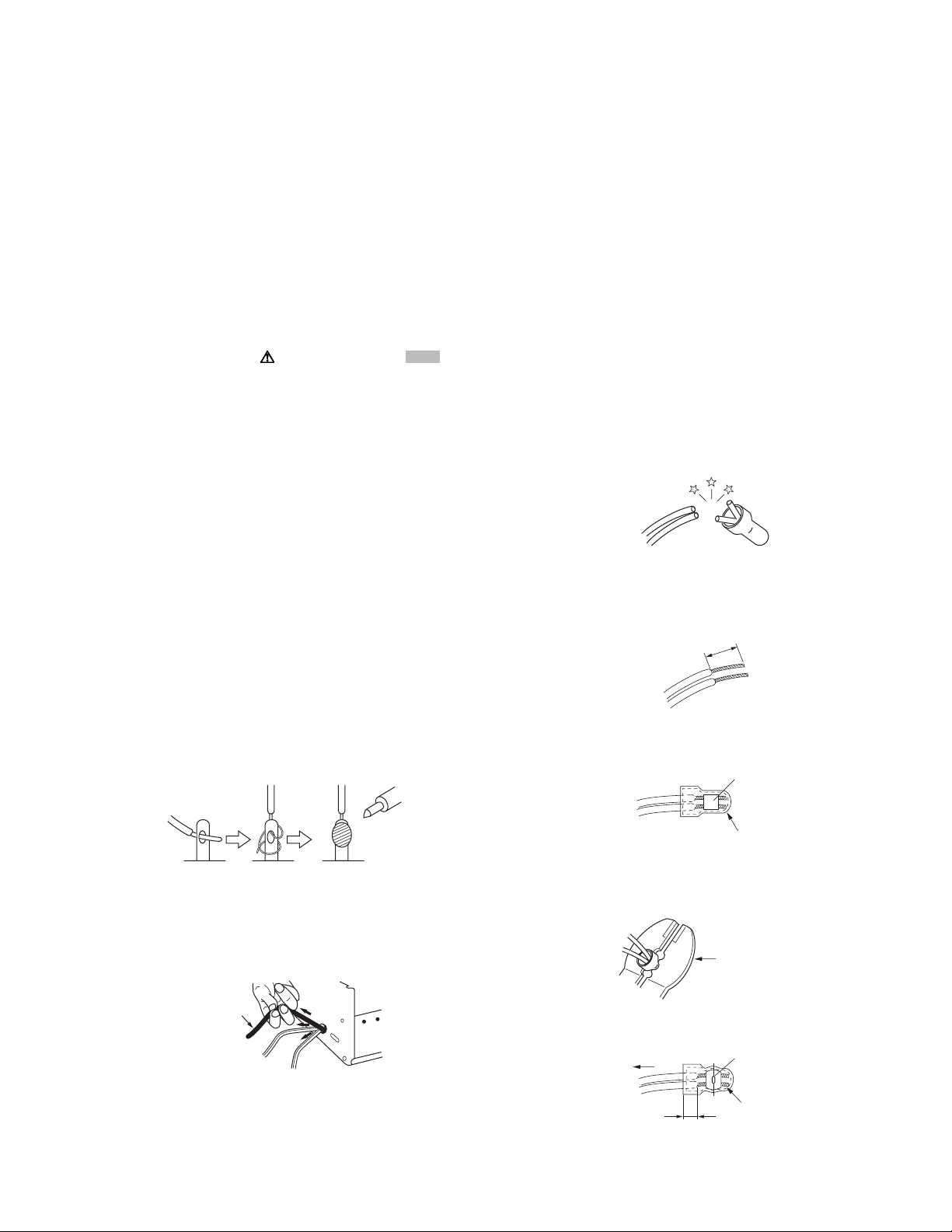
(12) Crimp type wire connectorIn such cases as when replacing
the power transformer in sets where the connections between the power cord and power trans former primary lead
wires are performed using crimp type connectors, if replacing the connectors is unavoidable, in order to prevent safety hazards, perform carefully and precisely according to the
following steps.
• Connector part number :E03830-001
• Required tool : Connector crimping tool of the proper
type which will not damage insulated parts.
• Replacement procedure
a) Remove the old connector by cutting the wires at a
point close to the connector.Important : Do not reuse a connector (discard it).
cut close to connector
Fig.1-1-3
b) Strip about 15 mm of the insulati on from the ends
of the wires. If the wires are stranded, twist the
strands to avoid frayed conductors.
15 mm
Fig.1-1-4
c) Align the lengths of the wires to be connected. In-
sert the wires fully into the connector.
Metal sleeve
Fig.1-1-1
(7) Observe that wires do not contact heat producing parts
(heatsinks, oxide metal film resistors, fusible resistors, etc.)
(8) Check that replaced wires do not contact sharp edged or
pointed parts.
(9) When a power cord has been replaced, check that 10-15
kg of force in any direction will not loosen it.
Power cord
Fig.1-1-2
(10) Also check areas surrounding repaired locations.
(11) Products using cathode ray tubes (CRTs)In regard to such
products, the cathode ray tubes themselves, the high voltage circuits, and related circuits are specified for compliance with recognized codes pertaining to X-ray emission.
Connector
Fig.1-1-5
d) As shown in Fig.1-1-6, use the crimping tool to crimp
the metal sleeve at the center position. Be sure to
crimp fully to the complete closure of the tool.
1.2
5
2
.0
5.5
Crimping tool
Fig.1-1-6
e) Check the four points noted in Fig.1-1-7.
Not easily pulled free
Wire insulation recessed
more than 4 mm
Crimped at approx. cente
of metal sleev
Conductors extended
Fig.1-1-7
(No.YD001)1-3
Page 4
1.1.2 Safety Check after Servicing
Examine the area surrounding the repaired location for d amage
or deterioration. Observe that screws, parts and wires have been
returned to original positions, Afterwards, perform the following
tests and confirm the specified values in order to verify compliance with safety standards.
(1) Insulation resistance test
Confirm the specified insulation resistance or greater between power cord plug prongs and externally exposed
parts of the set (RF terminals, antenna terminals, video and
audio input and output terminals, microphone jacks, earphone jacks, etc.).See table 1 below.
(2) Dielectric strength test
Confirm specified dielectric strength or greater between
power cord plug prongs and exposed accessible parts of
the set (RF terminals, antenna terminals, video and audio
input and output terminals, microphone jacks, earphone
jacks, etc.). See Fig.1-1-11 below.
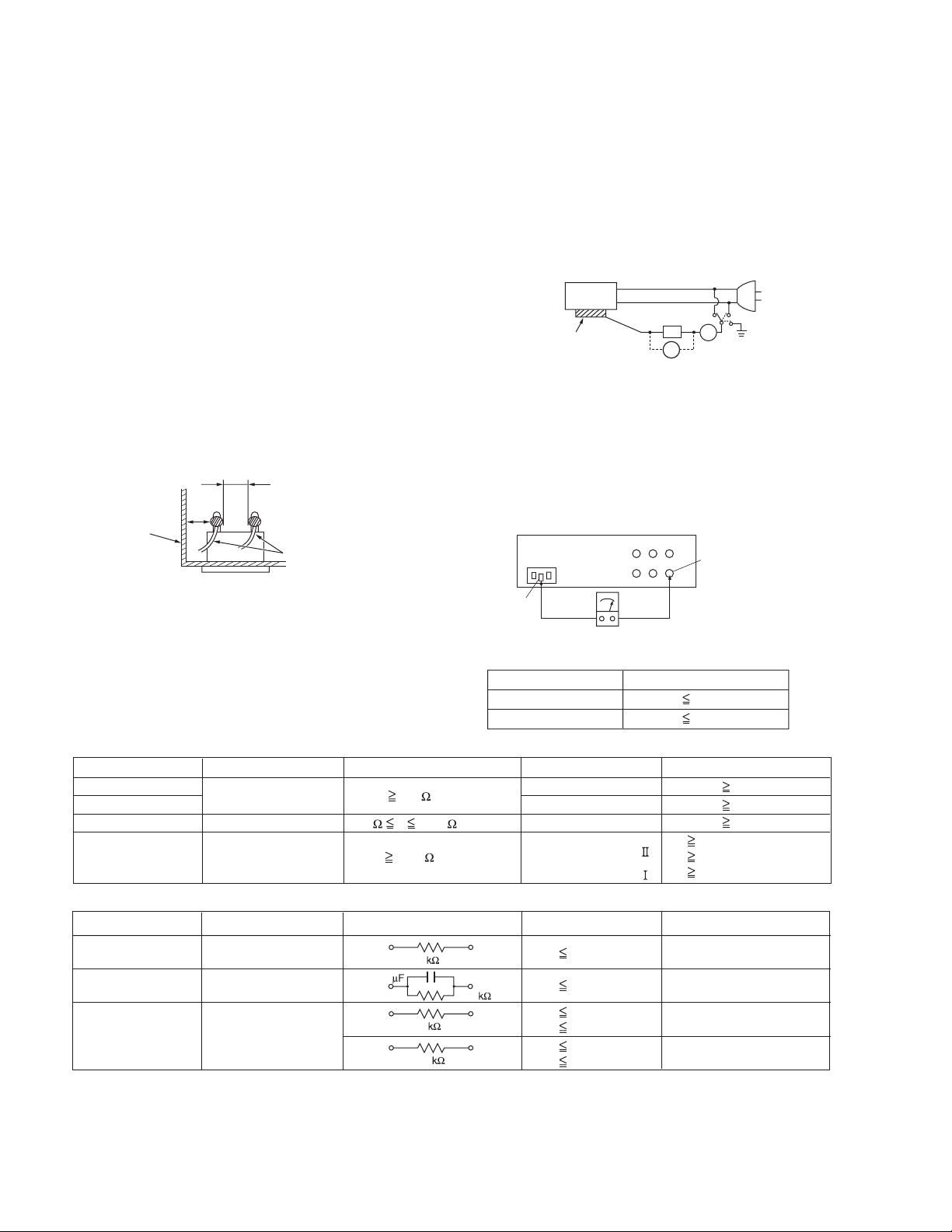
(3) Clearance distance
When replacing primary circuit components, confirm specified clearance distance (d), (d') between soldered terminals, and between terminals and surrounding metallic
parts. See Fig.1-1-11 below.
d
Chassis
d'
Power cord
primary wire
Fig.1-1-8
(4) Leakage current test
Confirm specified or lower leakage current between earth
ground/power cord plug prongs and externally exposed accessible parts (RF terminals, antenna terminals, video and
audio input and output terminals, microphone jacks, earphone jacks, etc.).
Measuring Method : (Power ON)Insert load Z between
earth ground/power cord plug prongs and externally exposed accessible parts. Use an AC voltmeter to measure
across both terminals of load Z. See Fig.1-1-9 and following Fig.1-1-12.
ab
Externally
exposed
accessible part
Z
V
c
A
Fig.1-1-9
(5) Grounding (Class 1 model only)
Confirm specified or lower grounding impedance between
earth pin in AC inlet and externally exposed accessible
parts (Video in, Video out, Audio in, Audio out or Fixing
screw etc.).Measuring Method:
Connect milli ohm meter between earth pin in AC inlet and
exposed accessible parts. See Fig.1-1-10 and grounding
specifications.
AC inlet
Earth pin
Exposed accessible part
MIlli ohm meter
Grounding Specifications
Region
USA & Canada
Europe & Australia
Grounding Impedance (Z
Z 0.1 ohm
Z 0.5 ohm
)
Fig.1-1-10
AC Line Voltage
100 V
100 to 240 V
110 to 130 V
110 to 130 V
200 to 240 V
Region
Japan
USA & Canada
Europe & Australia
Insulation Resistance (R
R 1 M /500 V DC
1 M R 12 M /500 V DC
R 10 M /500 V DC
)
Dielectric Strength
AC 1 kV 1 minute
AC 1.5 kV 1 minute
AC 1 kV 1 minute
AC 3 kV 1 minute
AC 1.5 kV 1 minute
(
Class
(
Class
Clearance Distance (d), (d'
d, d' 3 mm
d, d' 4 mm
d, d' 3.2 mm
d 4 mm
)
d' 8 mm (Power cord
d' 6 mm (Primary wire
)
Fig.1-1-11
AC Line Voltage
100 V
110 to 130 V
110 to 130 V
220 to 240 V
Region
Japan
USA & Canada
Europe & Australia
Load Z
1
0.15
1.5
2
50
Leakage Current (i)
i 1 mA rms
i 0.5 mA rms
i 0.7 mA peak
i 2 mA dc
i 0.7 mA peak
i 2 mA dc
a, b, c
Exposed accessible parts
Exposed accessible parts
Antenna earth terminals
Other terminals
Fig.1-1-12
NOTE :
These tables are unofficial and for reference only. Be sure to confirm the precise values for your particular country and locality.
)
)
)
1-4 (No.YD001)
Page 5
1.2 Preventing static electricity
Electrostatic discharge (ESD), which occurs when static electricity stored in the body, fabric, etc. is discharged, can destroy the laser
diode in the traverse unit (optical pickup). Take care to prevent this when performing repairs.
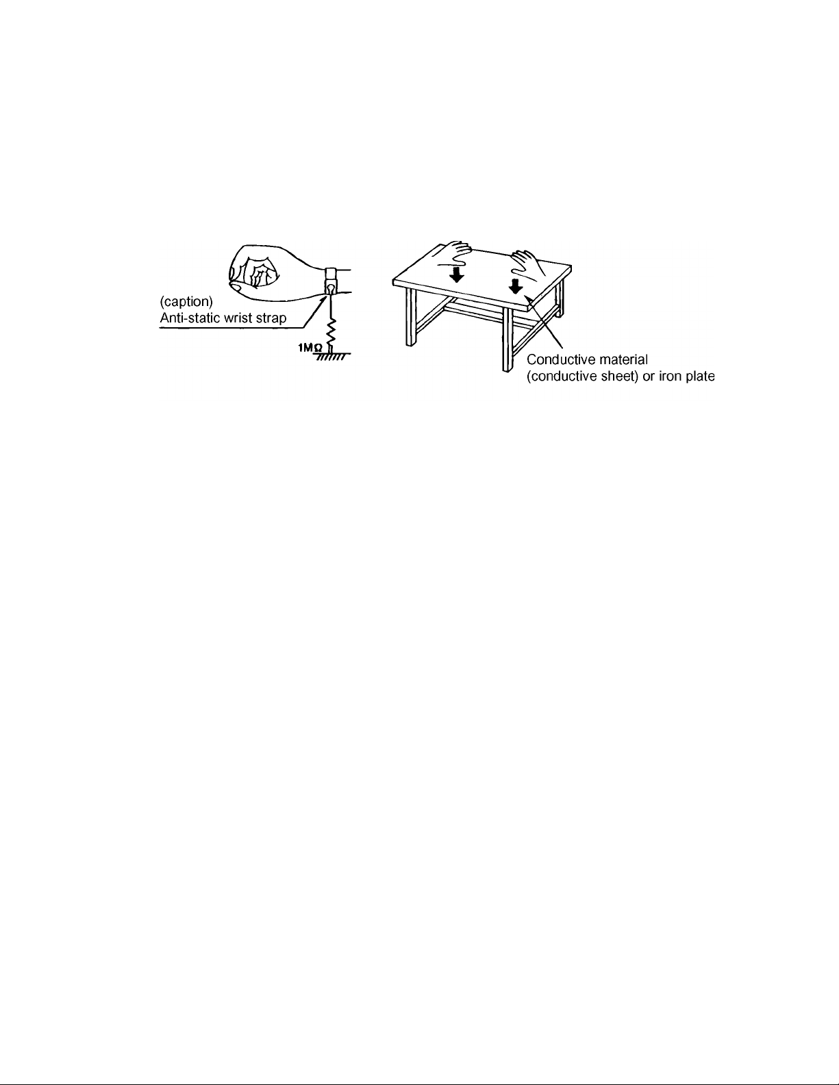
1.2.1 Grounding to prevent damage by static electricity
Static electricity in the work area can destroy the optical pickup (laser diode) in devices such as DVD players.
Be careful to use proper grounding in the area where repairs are being performed.
(1) Ground the workbench
Ground the workbench by laying conductive material (such as a conducti ve sheet) or an iron plate over it before placing the
traverse unit (optical pickup) on it.
(2) Ground yourself
Use an anti-static wrist strap to release any static electricity built up in your body.
(3) Handling the optical pickup
• In order to maintain quality during transport and before installatio n, both sides of the laser diod e on the replacement opti cal
pickup are shorted. After replacement, return the shorted parts to their original condition.
(Refer to the text.)
• Do not use a tester to check the condition of the laser diode in the optical pickup. The tester's internal power source can easily
destroy the laser diode.
(No.YD001)1-5
Page 6
1.3 Precautions for Service
1.3.1 Handling of Traverse Unit and Laser Pickup
(1) Do not touch any peripheral element of the pickup or the actuator.
(2) The traverse unit and the pickup are precision devices an d therefore must not be subjected to strong shock.
(3) Do not use a tester to examine the laser diode. (The diode can easily be destroyed by the internal power supply of the tester.)
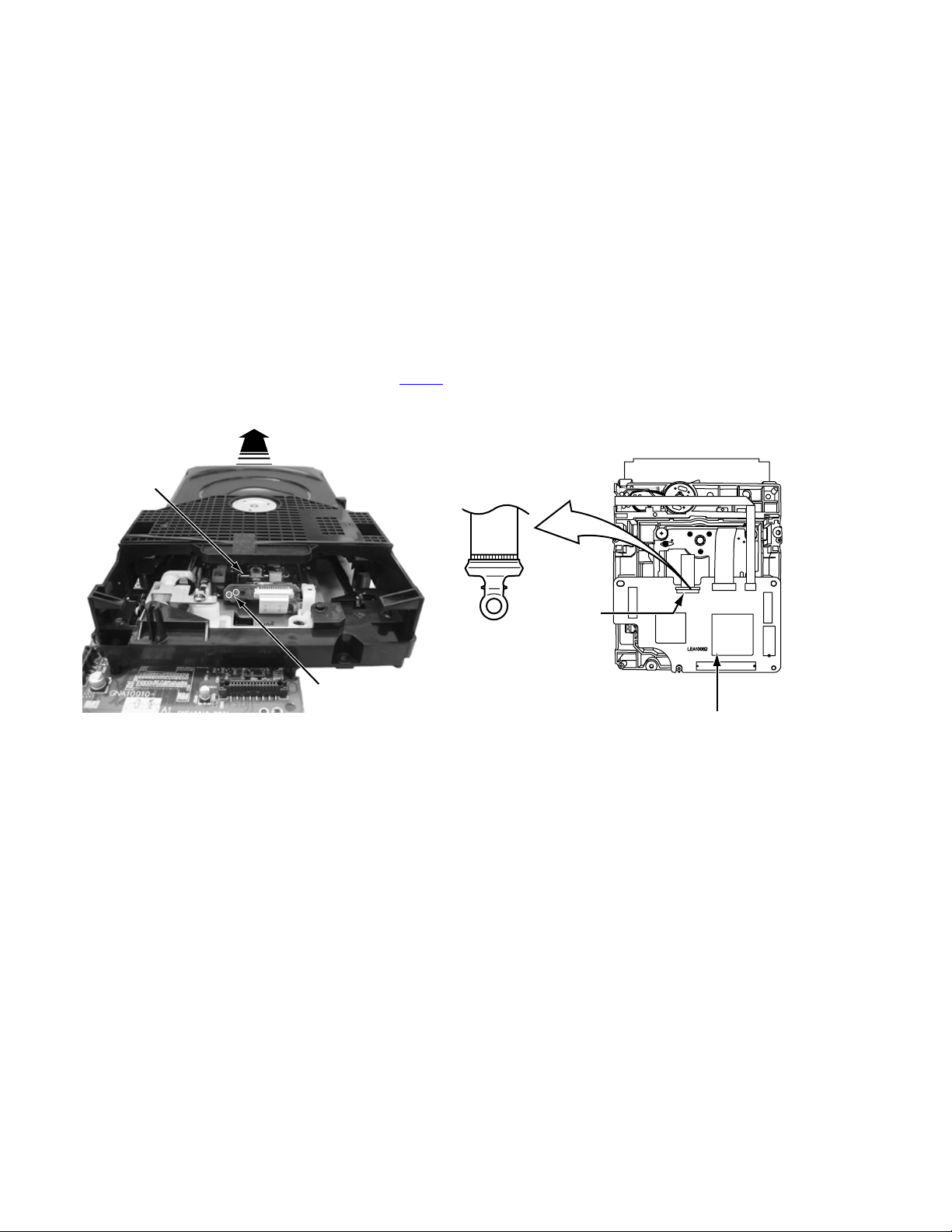
(4) To replace the traverse unit, pull out the metal short pin for protection from charging.
(5) When replacing the pickup, after mounting a new pickup, remove the solder on the short land which is provided at the center of
the flexible wire to open the circuit.
(6) Half-fixed resistors for laser power adjustment are adjusted in pairs at shipment to match the characteristics of the optical block.
Do not change the setting of these half-fixed resistors for laser power adjustment.
1.3.2 Destruction of Traverse Unit and Laser Pickup by Static Electricity
Laser diodes are easily destroyed by static electricity charged on clothingor the human body. Before repairing peripheral elements of
the traverse unit or pickup, be sure to take the following electrostatic protection:
(1) Wear an antistatic wrist wrap.
(2) With a conductive sheet or a steel plate on the workbench on which the traverse unit or the pick up is to be repaired, ground the
sheet or the plate.
(3) It solders to two short circuit sections on the substrate of a pick-up.
(4) After removing the flexible wire from the connector (CN101
(5) Short-circuit the laser diode by soldering the land which is provided at the center of the flexible wire for the pickup.
After completing the repair, remove the solder to open the circuit.
), short-circuit the flexible wire by the metal clip.
Pick-up
Short circuit
* Please refer to the SECTION3 DISASSEMBLY method for details.
CN101
DVD SERVO CONTROL BOARD
1-6 (No.YD001)
Page 7

SECTION 2
SPECIFIC SERVICE INSTRUCTIONS
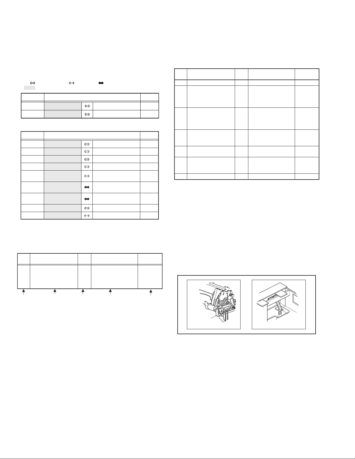
2.1 Different table of feature
The following table indicates main different points between models HR-XVC30US, HR-XVC33US, HR-XVC33UC, HR-XVC33UM, HRXVS44US, HR-XVS44UC, and HR-XVS44UJ.
HR-XVC30US HR-XVC33US HR-XVC33UC HR-XVC33UM HR-XVS44US HR-XVS44UC HR-XVS44UJ
POWER VOLTAGE 120V / 60Hz ←←
BODY COLOR BLACK PURE SILVER ←←←←←
REMOCON COLOR BLACK GRAY ←←←←←
S-VHS NOT USED ←←←USED ←←
S-VHS ET NOT USED ←←←USED ←←
SQPB USED ←←←NOT USED ←←
B.E.S.T. PICTURE NOT USED ←←←A.V.
PICTURE
CONTROL
REAR L-1 INPUT NOT USED ←←USED(V,L/R) USED(S,V,L/R) ←←
REMOTE PAUSE NOT USED ←←←←←USED
BACKUP TIME 5 SECONDS ←←3 MINUTES 5 SECONDS ←←
AUTO CLOCK /
JUST CLOCK
REC LINK / INPUT F-1 ←←L-1 ←←←
OSD LANGUAGES
[INITIAL]
REGION CODE
NORM/EDIT/
SOFT/SHARP
USED ←←NOT USED USED ←←
[ENGLISH],
SPANISH,
FRENCH
REGION CODE: 1
←←←AUTO/EDIT/
←←[ENGLISH],
←←
110-220V, 50/60Hz
SPANISH
REGION CODE: 4 REGION CODE: 1
120V / 60Hz ←
CALIBRATION
SOFT/SHARP
[ENGLISH],
SPANISH,
FRENCH
110-220V, 50/60Hz
←←
←←
←←
←←
NOTE :
Mark ← is same as left.
2.2 Service position
This unit has been designed so that the Mechanism an d Main
board assemblies can be removed together from the bottom
chassis. Before diagnosing or servicing the circuit boards, take
out the major parts from the bottom chassis.
2.2.1 How to set the "Service position"
(1) Refer to the disassembly procedure and perform the disas-
sembly of the major parts before removing the Mechanism
assembly.
(2) Remove the screws that fix the Mechanism, Regulator
board assembly to the bottom chassis. If any other screws
are used to fix the boards, remove them also.
(3) Remove the combined Mechanism,Regulator borad and
Main board assemblies.
(4) If any other major parts are used, remove them also.
(5) Connect the wires an d connectors of the major parts that
have been removed in steps (1) to (4). (Refer to Fig. 2-2a.)
(6) Place the combined Mechanism, Main board and other
board assemblies upside down.
(7) Insert the power cord plug into the power outlet and then
proceed with the diagnostics and servicing of the board as-
sembly.
Notes:
• Before inserting the power cord plug into the power out-
let, make sure that none of the electrical parts are able
to short-circuit between the workbench and the board
assembly.
• For the disassembly procedure of the major parts an d
details of the precautions to be taken, see "Removing
the major parts".
• If there are wire connections from the Main board and
Mechanism assemblies to the other major parts, be sure
to remove them (including wires connected to the major
parts) first before performing step (2).
• When carrying out diagnosis and repair of the Main
board assembly in the "Service position", be sure to
ground both the Main board and Mechanism assemblies. If they are improperly grounded, there may be
noise on the playback picture or FDP counter display
may move even when the mechanism is kept in an inoperative status.
• In order to diagnose the playback or recording of the
cassette tape, set the Mechanism assembly to the required mode before placing it upside do wn. If the mechanism mode is changed (including ejection) while it is in
an upside down position the tape inside may be damaged.
(No.YD001)1-7
Page 8
• For some models, the mechanism and board assem-
blies are attached by connectors only. When carr ying
out a diagnosis or repair of the boards in the "Service
position", make sure that the connectors are not di sconnected.
Regulator board assembly
TP111 D.FF
TP4001 CTL.P
TP106 PB FM
TP2253 A.PB FM
Display board assembly
Main board assembly
Jack board assembly
Fig.2-2a
2.3 Jig RCU mode
This unit uses the following two modes for receiving remote control codes.
(1) User RCU mode:Ordinary mode for use by the user.
(2) Jig RCU mode: Mode for use in production and servicing.
When using the Jig RCU, it is required to set the VCR to the Jig
RCU mode (the mode in which codes from the Jig RCU can be
received). As both of the above two modes are stored in the EEPROM, it is required to set the VCR back to the User RCU mode
each time that an adjustment is made or to check that the necessary operations have been completed.These modes can be set
by the operations described below.
Note:
• Confirm the RCU mode when exchanged parts. Since
some SERVICE PARTS sets the VCR to the Jig RCU
mode as initial setting. Therefore please set the VCR to
the user RCU mode after replacing the EEPROM.
User RCU mode
CH
2.3.2 Setting the User RCU mode
(1) Turn off the power.
(2) Press the "REC" and "PAUSE" buttons of the VCR simul-
taneously. Alternatively, transmit the code "80" from the Jig
RCU.
2.4 Mechanism service mode
This model has a unique function to enter the mechanism into every operation mode without loading of any cassette tape. This
function is called the "Mechanism service mode".
2.4.1 How to set the "Mechanism service mode"
(1) Set the VCR to the Jig RCU mode (the mode in which
codes from the Jig RCU can be received)
(2) Transmit the code "E5" from the Jig RCU.
(3) Release the lug of th e Cassette holder and then slid e the
Cassette holder toward the direction where the Cassette
holder is loaded by manually.
(4) The cassette holder lowers and, when the loading has
completed, the mechanism enters the desired mode.
When the VCR is set to the Mechanism service mode, the
symbols ("Timer") in the FDP (LED) are blinked.
2.4.2 How to exit from the "Mechanism service mode"
(1) Unplug the power cord plug from the power outlet.
2.5 As for distinction between two kinds of Main boards
Either of the two different kinds of Main boards is used for HRXVC30US, HR-XVC33US, HR-XVC33UC, and HR-XVC33UM,
according to a period of production.Since the two types of boards
have different circuits and parts numbers, check what type of
board is used for the product before your analysis and repair
work.The following is how to distinguish the Main board.
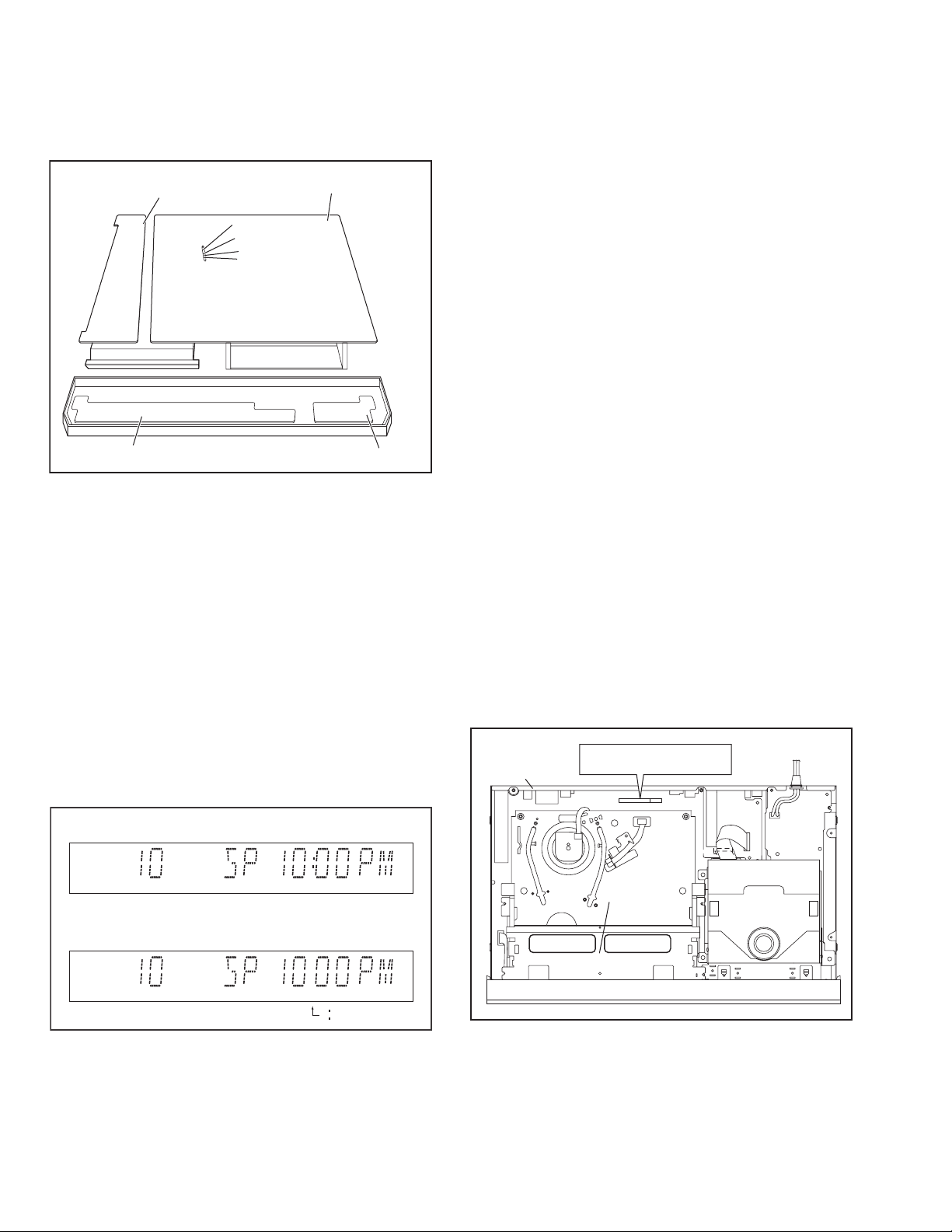
(1) Remove the Top cover. (See “SECTION 3 Removing the
major parts”)
(2) Check whether "CN501" is printed in a space between the
Mechanism Assembly and the Rear cover. (See Figure 2-
5a.)
With CN501: LPB10207 type
Without CN501: LPB10221 type
With CN501 : LPB10207 type
Rear cover
Without CN501 : LPB10221 type
CN501
CN2001
CN7101
A/C HEAD
CN6201
CN5001
Jig RCU mode
CH
(ޓnot displayed)
Fig.2-3a User/Jig RCU mode
2.3.1 Setting the Jig RCU mode
(1) Turn on the power.
(2) Press the following remocon keys continuously within 2
seconds " SET UP MENU " → " 2 " → " 8 " → " OK ".
When the VCR is set to the Jig RCU mode, the symbols
( " : " ) in the time display of the FDP are turned off.
(Refer to Fig.2-3a)
1-8 (No.YD001)
CN7103
Mechanism assembly
Fig.2-5a
Page 9
2.6 Maintenance and inspection
2.6.1 Cleaning
Regular cleaning of the transport system parts is desirable but
practically impossible. So make it a rule to carry out cleaning of
the tape transport system whenever the machine is serviced.
When the video head, tape guide and/or brush get soiled, the
playback picture may appear inferior o r at worst disappear, resulting in possible tape damage.
Note:
• Absolutely avoid sweeping the upper drum vertically as
this will cause damage to the video head.
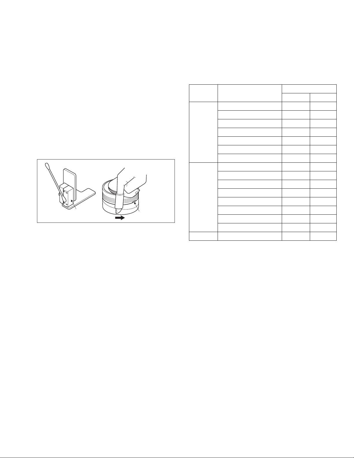
(1) When cleaning the upper drum (especially the video head),
soak a piece of closely woven cloth with alcohol and while
holding the cloth onto the upper drum by the fingers, turn
the upper drum counterclockwise.
(2) To clean the parts of the tape transport system other than
the upper drum, use a piece of closely woven cloth or a cotton swab soaked with alcohol.
(3) After cleaning, make sure that the cleaned parts are com-
pletely dry before using the cassette tape.
A/C head
Video heads
Fig.2-6a
2.6.2 Lubrication
With no need for periodical lubrication, you have only to lubricate
new parts after replacement. If any oil or grease on contact parts
is soiled, wipe it off and newly lubricate the parts.
Note:
• See the "mechanism assembly" diagram of the "parts
list" for the lubricating or greasing sp ots, and for the
types of oil or grease to be used.
2.6.3 Suggested servicing schedule for main components
The following table indicates the suggested period for such service measures as cleaning, lubrication and replacement. In practice, the indicated periods will vary widely according to
environmental and usage conditions. However, the indicated
components should be inspected when a set is brought for service and the maintenance work performed if necessary. Also
note that rubber parts may deform in time, even if the set is not
used.
System Parts name
Operation hours
1000H 2000H
Drum assembly C,X X
A/C head C,X C,X
Pinch roller arm assembly C C
Tape
transport
Full erase head C C
Tension arm assembly C C
Capstan motor (Shaft) C C
Guide arm assembly C C
Capstan motor X
Capstan brake assembly X
Main brake assembly X
Drive
Belt (Capstan) X X
Loading motor X
Clutch unit X
Worm gear X
Control plate X
Other Rotary encoder X
C : Cleaning
X : Inspection or Replacement if necessary
(No.YD001)1-9
Page 10
SECTION 3
DISASSEMBLY
3.1 Removing the major parts
3.1.1 Destination of connectors
Two kinds of double-arrows in connection tables respectively
show kinds of connector/wires.
: The connector of the side to remove
CONN. No. PIN No.CONNECTOR
WR2a
WR2b
Main CN101
Main CN103
Destination of connectors
CONN. No. PIN No.CONNECTOR
WR2a
WR2b
WR2c
WR3a
WR3b
CN5302
(CN501)
CN7301
(CN502)
WR6a
WR6b
Main
Main
Main
Main
Drum
assembly
Regulator
Main
Regulator
Regulator
3.1.2 How to read the procedure table
This table shows the steps for disassembly of the externally furnished parts and board assemblies. Reverse these steps when
re-assembling them.
Step/
Loc No.
[1] Top cover 3-1a
Part Name
Bracket 2(S1c)
: Wire: Flat wire : Board to board (B-B)
Digital CN761
Digital CN762
CN7103
CN3102
CN3103
CN2001
CN5302
CN7301
CN5303
CN5301
Jack
Display
Display
A/C head
Main
DVD
servo control
DVD
servo control
Main
Main
Fig.
No.
4(S1a),(S1b),3(L1a), <Note 1a>
2(SD1a),(P1a),(W1a),
CN1(WR1a),
----------------------------------------
CN7191
CN7003
CN7004
CN1
CN501
CN502
CN5313
CN5311
Point Note
40
10
11
14
14
6
9
22
22
11
11
3.1.3 Disassembly procedure
Step/
Loc No.
[1]
[2]
[3]
[4]
[5]
[6]
[7]
Part Name
Top cover
Front panel assembly
(Display board assembly)
(Jack board assembly)
Mechanism assembly
(Drum assembly)
DVD unit
(Bracket)
Rear cover
Regulator board assembly
Main board assembly
Fig.
No.
3-1d
3-1a
3-1d
3-1b
3-1c
3-1d
3-1d
3-1d
3-1d
3-1d
Point Note
6(S1a)
4(L2a),5(L2b),2(S2a)
CN7103(WR2a),
CN3102(WR2b),
CN3103(WR2c),
CN2001(WR3a)
3(S3a),(S3b)
--------------------------
CN(WR3b)
(S3c),(S3d),(S3e)
3(S4a),(L4a)
3(S4b),CN5302(CN501)
CN7301(CN502)
2(S5a),(S5b),5(S5c),
3(L5a)
3(S6a)
CN5303(WR6a),
CN5301(WR6b)
3(S7a)
<Note 2a>
<Note 2b>
<Note 2a>
<Note 3a>
<Note 3b>
<Note 3c>
<Note 2a>
<Note 2a>
• Be careful not to damage the connector and wire etc. during
connection and disconnection.
• When connecting the flat wire to the connector, be careful with
the flat wire direction.
<Note 2b>
• When reattaching the Front panel assembly, make sure that
the door opener of the Side frame (R) is lowered in position prior to the reinstallation.
• When reattaching the Front panel assembly, pay careful attention
to the switch lever of the Front panel assembly not to make it
touch the switch knob of the Main board assembly from the side.
• When reattaching the Front panel assembly, lift the Cassette
door slightly.
(1) (2) (3) (4) (5)
(1) Order of steps in Procedure
When reassembling, perform the step(s) in the reverse order.
These numbers are also used as the identification (loca-
tion) No. of parts Figures.
(2) Part name to be removed or installed.
(3) Fig. No. showing procedure or part location.
(4) Identification of part to be removed, unhooked, unlocked,
released, unplugged, unclamped or unsoldered.
P= Spring, W= Washer, S= Screw, L= Locking tab, SD=
Solder, CN**(WR**)= Remove the wire (WR**) from the
connector (CN**).
Note:
• The bracketed ( ) WR of the connector symbol are
assigned nos. in priority order and do not correspond to those on the spare parts list.
(5) Adjustment information for installation
1-10 (No.YD001)
Door
opener
Side
frame(R)
Switch
knob
Switch
lever
Fig.3-1a
<Note 3a>
• When reattaching the Mechanism assembly, secure the
screws (S3a to S3b) in the order of 1,2,3.
<Note 3b>
• When reattaching the Mechanism assembly, be sure to align
the phase of the Rotary encoder on the Main board assembly.
• When reattaching the Mechanism assembly, set the “Mechanism assembling mode”. [See “MECHANISM ASSEMBLY
SERVICE MANUAL (No. 86700)”.]
• When reattaching the Mechanism assembly to the Main board
assembly, take care not to damage the sensors and switch on
the Main board assembly.
Page 11
<Note 3c>
• When reattaching the Drum assembly, secure the screws (S3c
to S3e) in the order of c, d, e.
Mechanism
assembly
(S3d)
(S3c)
(S3e)
(S3d)
(S3e)
Drum
assembly
<Note 3c>
<NOTE>
Attach the Drum assembly appropriately,
since the installation state of the Drum assembly
influences the FM WAVEFORM LINEARITY
greatly.
(S3c)
HOOK
Fig.3-1b
• When handling the drum assembly alone, hold it by the motor
or shaft. Be careful not to touch other parts, especially the video heads. Also take care not to damage the connectors.
Shaft
Motor
Video heads
Fig.3-1c
(No.YD001)1-11
Page 12

1.Insert direction of FCC WIRE as follows.
electrode side
NOTE
right side back side
supporting side
2.FFC WIRE and DRUM FPC WIRE should be insert as follows.
OK
90
CN CN CN
3.Insert the wire to even the root of connector completely
at the same time as inserting each wire.
4.Check to see that outside parts.TOP COVER,BOTTOM COVER,
FRONT PANEL, etc are fixed certainly to the BOTTOM CHASSIS
with SCRWES.
NG
5.Pay attention NOT to make any scratches on FRONT PANEL.
6.Pay close attention not to cut any Sheath of WIRE by sharp edge
of CHASSIS while Wireing Process.
[3] Drum assembly
(S3a)
1
[3] Mechanism assembly
f
(S3a)
3
f
(S3c)
b
(S3e)
(S3d)
(S7a)
(S7a)
[7]Main board assembly
(S1a)
(S3b)
(S3a)
2
(S7a)
(S1a)
[1]Top cover
(S5a)
(S5b)
(S5c)
(S5a)
(L5a)
(S5c)
[5]Rear cover
(L5a)
(L5a)
<Phase alignment>
JS3001JS3001
.
Accord the position of V gap on R.ENCORDER and PWB silk
.
Accord the position of Boss on R.ENCORDER and PWB silk
(S4a)
(S1a)
(S1a)
(S4a)
[4]DVD unit
(L2b)
Cassete door
<Note2b>
Jack board assembly
CN7191
(WR2a)
<Note2a>
(L2b)
(L2a)
(S2a)
(L2a)
[2]Front panel assembly
Bottom side
Top side
(L2b)
CN7301
(WR2b)
<Note2b>
Display board assembly
(WR2c)
<Note2b>
CN7004
CN7003
(L4a)
(S4b)
(S4a)
[4]Bracket
CN502
DVD servo control board assembly
(S6a)
CN5302
(S4b)
(S6a)
(S6a)
[6]Regulator board assembly
Must confirm soldering condition as no soldering and
dry soldering at portion of Power cord lead on REG/FRONT
pwb before attach Main pcb to Bottom chassis.
Insert the bushing of POWER CORD so as not to twist the cord.
(WR3b)
<Note2b>
CN2001
(WR3a)
<Note2b>
CN7103
CN7101
CN3102
CN3103
CN6201
B
CN5311CN5313
CN5001
A
(WR6a)
<Note2b>
CN5303 CN5301
(WR6b)
<Note2b>
CN501
1-12 (No.YD001)
Jack board assembly
Fig.3-1d
CN7191
Page 13

3.2 Loading mechanism assembly
Projection of the tray
3.2.1 Removing the tray (See Figure 3-2a, Figure 3-2b, Figure 3-2c, Figure 3-2d, Figure 3-2e, Figure 3-2f)
(1) Push a of the sl ide cam on the hole in the rig ht side of the
loading base by using a driver until it stops. (See Figure 32a.)
(2) The tray comes out. Pull the tray in a front direction u ntil it
stops.
(3) Remove the two screws A attaching the slide bracket. (See
Figure 3-2b.)
(4) Tilt the tray in a direction of the arrow around the point in
the left rear part of the tray. (See Figure 3-2c.)
(5) The rail of the tray is remove d from b of the loadi ng base.
Then, remove the tray upward. (See Fig u re 3-2d.)
Attaching the tray:
Engage c of the loading base to the projection of the tray while
tilting the tray to the left. Turn the tray in a di rection of the arrow, and attach the slide bracket. (See Figure 3-2e.)
Note:
Prior to the procedure above, move the slide cam in a direction
of the arrow so that d of the slide cam can be inserted in e of
the tray. (See Figure 3-2f.)
Tray
The point in the left rear part
Fig.3-2c
Tray
Push
Slide cam part a
Slide bracket
A
Fig.3-2a
Fig.3-2b
A
Loading base
Tray
Loading base part b
Rail of the tray
Fig.3-2d
Projection of the tray
Loading base part c
Fig.3-2e
Part e
Part d
Slide cam
Fig.3-2f
(No.YD001)1-13
Page 14

3.2.2 Removing the traverse mechanism assembly (See Figure 3-2g)
f
Shaft
Reverse the loading mechanism assembly. Remove the four
screws B attaching the traverse mechanism assembly. Remove
the traverse mechanism assembly upward.
Loading mechanism assembly
3.2.3 Removing the elevator (See Figure 3-2h and Figure 3-2j)
• Prior to the following procedure, remove the traverse mechanism assembly.
(1) Remove the two arms of the elevator from the two parts f
by moving the arms in a direction of the arrow.
(2) Pull out the elevator in a rear direction.
Attaching the elevator:
Engage the two holes g to the two shafts on the front part of
the elevator. And then, attach the elevator.
B
B
B
B
Traverse mechanism assembly
Fig.3-2g
Elevator
1-14 (No.YD001)
Part f
Fig.3-2h
g
Slide cam
Elevator
Shaft
Fig.3-2j
Part
g
Page 15

3.2.4 Removing the loading motor (See Figure 3-2k and Figure 3-2l)
• Prior to the following procedure, remove the tray, the traverse
mechanism assembly, and the elevator.
(1) Remove the belt from the pulley.
(2) Remove two screws C attaching the loading motor.
(3) Remove two solders h on the switch board.
Switch board
Pulley
Part h
Belt
Pulley
C
Fig.3-2k
Loading base
Slide cam
C
Loading motor
3.3 Traverse mechanism assembly
3.3.1 Removing the pickup (See Figure 3-3a, Figure 3-3b)
• Prior to the following procedure, remove the traverse mechanism assembly.
(1) Remove one screw D attaching the plate.
(2) Remove the plate and the leaf spring.
(3) Lift i of the shaft 1, and pull out the shaft 1 from j.
(4) Remove k of the pickup from the shaft 2.
Attaching the pickup:
(1) Engage k of the pickup to the shaft 2.
(2) Insert the shaft 1 in j, and attach the shaft 1 to i.
(3) Attach the leaf spri ng, and then atta ch the plate. Fi x the
leaf spring and the plate by using the screw D.
Fig.3-2l
D
Leaf spring
Plate
Fig.3-3a
Shaft 2
Part k
Part j
Shaft 1
Part i
Fig.3-3b
(No.YD001)1-15
Page 16

SECTION 4
ADJUSTMENT
4.1 Before adjustment
4.1.1 Precaution
• The adjustments of this unit include the mechanism com-
patibility and electrical adjustments. During the performance of this work, be sure to observe the precautions for
each type of adjustment.
• If there is a reference to a signal input method in the signal
column of the adjustment chart, “Ext. S-input” means the
Y/C separated video signal and “Ext. input” means the
composite video signal input.
• Unless otherwise specified, all measuring points and
adjustment parts are located on the Main board.
4.1.2 Required test equipments
• Color (colour) television or monitor
• Oscilloscope: wide-band, dual-trace, triggered delayed sweep
• Signal generator: RF / IF sweep / marker
• Signal generator: stairstep, color (colour) bar [NTSC]
• Recording tape
• Digit-key remote controller(provided)
4.1.3 Required adjustment tools
--- : Not used
z
: Used
Mechanism
compatibility
adjustment
Roller driver z
Jig RCU --- z
Back tension cassette gauge z
Alignment tape(MHP) z ---
Alignment tape(MHP-L) zz
Roller driver
PTU94002
Alignment tape
(SP, stairstep, NTSC)
MHP
Jig RCU
PTU94023B
Alignment tape
(EP, stairstep, NTSC)
MHP-L
Back tension cassette gauge
Electrical
adjustment
---
---
PUJ48076-2
DVD test disc
VT-501
4.1.4 Color (colour) bar signal,Color (colo ur) bar pattern
Color(colour) bar signal [NTSC]
White(100%)
White(75%)
100 IRE
1V
40 IRE
Horizontal sync
Yellow
Cyan
Green
Magenta
Red
QI
Blue
Burst
Color(colour) bar pattern [NTSC]
(75%)
Cyan
White
40 IRE
Q I Black
Yellow
White
100%
Green
Magenta
Red
Blue
4.1.5 Switch settings
When adjusting this unit, set the VCR mode and switches
as described below.
• When using the Jig RCU, it is required to set the VCR to the
Jig RCU mode (the mode in which codes from the Jig RCU can
be received). (See "section 2 SPECIFIC SERVICE INSTRUCTIONS".)
Jig RCU
[Data transmitting method]
Depress the " "( 3 ) button
after the data code is set.
CUSTOM CODE
43: A CODE
DATA CODE
INITIAL MODE
Fig.4-1a Jig RCU [PTU94023B]
• Set the switches as shown below unless otherwise specified
on the relevant adjustment chart. The switches that are not listed below can be set as desired.
If the VCR is not equipped with the functions detail ed below,
setup is not required.
AUTO PICTURE/VIDEO CALIBRATION/
B.E.S.T./D.S.P.C.
PICTURE CONTROL/SMART PICTURE NORMAL/NATURAL
VIDEO STABILIZER OFF
TBC ON
Digital 3R ON
VIDEO NAVIGATION/TAPE MANAGER OFF
BLUE BACK OFF
OFF
CD-DA test disc
CTS-1000
1-16 (No.YD001)
Page 17

4.1.6 Manual tracking mode (Auto tracking ON/OFF) setting
(1) In order to set to the manual tracking mode during tape
playback, press the “SP/EP(LP)”button on the remote control unit.
• Each press of the button switches the auto tracking ON
or OFF.
• When the manual tracking mode is set, the tracking is
placed at the center position.
(2) Press “channel +/-” to adjust the tracking ma nually.
4.1.7 EVR Adjustment
Some of the electrical adjustments require the adjustment performed by the EVR system. The main unit have EEPROMs for
storing the EVR adjustment data and user setups.
Notes:
• In the EVR adjustment mode, the value is varied with the
channel buttons (+, –). The adjusted data is stored when
the setting mode changes (from PB to STOP, when the
tape speed is changed, etc.). Take care to id entify the
current mode of each adjustmen t item when ma king a n
adjustment.
• When changing the address setting in the EVR adjust-
ment mode, use the Jig RCU or the remote controller
having numeric keypad with which a numeric code ca n
be directly input.
The remote control code of the Jig RCU corresponds to
each of the digit keys on the remote controller as follows.
Digit-key0123456789
Code 20 21 22 23 24 25 26 27 28 29
• As the counter indication and re maining ta pe indicat ion
are not displayed FDP during the EVR adjustment
mode, check them on the TV monitor screen.
• When performing the EVR adjustment, confirm that the
FDP indication is changed to the EVR mode, as shown
below.
FDP
Fig.4-1b EVR mode
4.2 Mechanism compatibility adjustment (VHS SECTION) Notes:
• Although compatibility adjustment is very important, it
is not necessary to perform this as part of the normal
servicing work. It will be required when you have replaced the A/C head, drum assembly or any p art of the
tape transport system.
• To prevent damaging the alignment tape in the compat-
ibility adjustment, prepare a cassette tape (for self-recording/playback), perform a test on it by transporting it
and making sure that the tape is not bent by the tap e
transport mechanisms such as in the guide rollers.(See
Fig.4-2b.)
4.2.1 Tension pole position
Notes:
• This adjustment must be performed every time the ten-
sion band is replaced.
Signal (A) • Back tension cassette gauge [PUJ48076-2]
Mode (B1)
Adjustment part (F) • Adjust pin [Mechansim assembly]
Specified value (G)
•PB
(B2)
• Eject end
• 25 - 51 gf•cm (2.45 - 5 x 10
-3
Nm)
(1) Play back the back tension cassette gauge (A).
(2) Check that the indicated value on the left side gauge is
within the specified value (G).
(3) If the indicated value is not within th e specified value (G),
perform the adjustment in a following procedure.(See
Fig.4-2a.)
a) Remove the top frame, cassette holder and side
frames (L/R) all together. (Refer to the SERVICE
MANUAL No.86700 [MECHANISM ASSEMBLY].)
b) Rotate the loading motor gear to move the control
plate so that the triangular stamping to the left of the
“P”stamping is aligned with the stamping (a) on the
main deck. This positioning is mode (B1).
c) Adjust by turning the adjustment pin so that the tip of
the tension arm is aligned with the stamping (b) on
the main deck.
d) Rotate the reel disk (S) by about one turn clockwise
and make sure that the round hole of the adjustment
pin is located in the “OK” range. If it is outside this
range, restart the adjustment from the beginning.
After completion of the adjustment, rotate the loading gear
motor to return it to the mode (B2) position.
TENSION ARM
Stamping(b)
OK
ADJUST PIN
CONTROL PLATE
Stamping(a)
NG
Fig.4-2a
(No.YD001)1-17
Page 18

4.2.2 FM waveform linearity
Signal (A1)
Mode (B) • PB
Equipment (C) • Oscilloscope
Measuring point (D) • TP106 (PB. FM)
External trigger (E) • TP111 (D.FF)
Adjustment part (F) • Guide roller [Mechanism assembly]
Specified value (G) • Flat V.PB FM waveform
Adjustment tool (H) • Roller driver [PTU94002]
• Alignment tape(SP, stairstep, NTSC) [MHP]
(A2)
• Alignment tape(EP,stairstep,NTSC) [MHP-L]
(1) Play back the alignment tape (A1).
(2) Apply the external trigger signal to D.FF (E), to observe
the V.PB FM waveform at the measuring point (D).
(3) Set the VCR to the manual tracking mode.
(4) Make sure that there is no significant level drop of the V.PB
FM waveform caused by the tracking operation, with its
generally parallel and linear variation ensured. Perform the
following adjustments when required. (See Fig. 4-2c.)
(5) Reduce the V.PB FM waveform by the tra cking operatio n.
If a drop in level is found on the left side, turn the guide roll-
er of the pole base assembly (supply side) with the roller
driver to make the V.PB FM waveform linear.
If a drop in level is on the right side, likewise turn the guide
roller of the pole base assembly (take-up side) with the
roller driver to make it linear. (See Fig. 4-2c.)
(6) Make sure that the V.PB FM waveform varies in parallel
and linearly with the tracking operation again. When re-
quired, perform fine-adjustment of the guide roller of the
pole base assembly (supply or take-up side).
(7) Unload the cassette tape once, play back the alignment
tape (A1) again and confirm the V.PB FM waveform.
(8) After adjustment, confirm that the tape wrinkling does not
occur at the roller upper or lower limits. (See Fig. 4-2b.)
[Perform adjustment step (9) only for the models equipped
with SP mode and EP (or LP) mode.]
[Perform adjustment step (9) only for the models
equipped with SP mode and EP (or LP) mode.]
(9) Repeat steps (1) to (8) by using the alignment tape (A2).
Improper
(a)
GUIDE ROLLER
(b)
GUIDE POLE
Proper
Fig.4-2b
Proper waveform variation
Improper waveform variation
A
C
Up Down
B
D
Roller driver
Guide roller
(supply side)
Fig.4-2c
4.2.3 Height and tilt of the A/C head
Note:
• Set a temporary level of the height of the A/C head in ad-
vance to make the adjustment easier after the A/C head
has been replaced. (Refer to the SERVICE MANUAL
No.86700 [MECHANISM ASSEMBLY].)
Signal (A) • Alignment tape(SP, stairstep, NTSC) [MHP]
Mode (B) • PB
Equipment (C) • Oscilloscope
Measuring point (D1)
External trigger (E) • TP111 (D.FF)
Adjustment part (F) • A/C head [Mechanism assembly]
Specified value (G) • Maximum waveform
• TP106 (PB. FM)
(D2)
• TP4001 (CTL. P)
(1) Play back the alignment tape (A).
(2) Apply the external trigger signal to D.FF (E), to observe the
AUDIO OUT waveform and Control pulse waveform at the
measuring points (D1) and (D2) in the ALT mode.
(3) Set the VCR to the manual tracking mode.
(4) Adjust the AUDIO OUT waveform and Control pulse wave-
form by turning the screws (1), (2) and (3) little by little until
both waveforms reach maximum. The screw (1)
and (3) are for adjustment of tilt and the screw (2) for azi-
muth.
Head base
(2)
(1)
AUDIO OUT
1-18 (No.YD001)
A/C head
CTL. P
(3)
Fig.4-2d
Page 19

4.2.4 A/C head phase (X-value)
Signal (A1)
Mode (B) • PB
Equipment (C) • Oscilloscope
Measuring point (D) • TP106 (PB. FM)
External trigger (E) • TP111 (D.FF)
Adjustment part (F) • A/C head base [Mechanism assembly]
Specified value (G) • Flat V.PB FM waveform
Adjustment tool (H) • Roller driver [PTU94002]
• Alignment tape(SP, stairstep, NTSC) [MHP]
(A2)
• Alignment tape(EP,stairstep,NTSC) [MHP-L]
(1) Play back the alignment tape (A1).
(2) Apply the external trigger signal to D.FF (E), to observe the
V.PB FM waveform at the measuring point (D).
(3) Set the VCR to the manual tracking mode.
(4) Loosen the screws (4) and (5), then set the Roller driver to
the innermost projected part of the A/C head. (See Fig. 4-
2e.)
(5) Rotate the roller driver so that the A/C head comes closest
to the capstan. From there, move the A/C head back grad-
ually toward the drum until the point where the FM wave-
form is maximized for the second time, and then
tighten the screws (4) and (5) temporarily.
(6) Play an alignment tape (A2) and set to the manual-tracking
mode.
(7) Fine-adjust A/C head base position to maximize the FM
waveform, and then tighten the screws (4) and (5) firmly.
(8) Play alignment tapes (A1) and (A2) and confirm that th e FM
waveforms are maximized when the tracking is at the cen-
ter position.
To the drum
Toward the capstan
Toward the drum
A/C head
Screw (5)
Roller driver
Screw (4)
Head base
To the capstan
Fig.4-2e
Alignment tape
[SP, stairstep]
played with the
SP head
Waveform output
X-value adjustment point
Drum side Control head position Capstan side
Alignment tape
[EP(LP), stairstep]
played with the
EP(LP) head
Maximum
Fig.4-2f
4.3 Electrical adjustment (VHS SECTION) Note:
The following adjustment procedures are not only necessary
after replacement of consumable mechanical parts or bo ard
assemblies, but are also provided as references to be referred
to when servicing the electrical circuitry.
In case of trouble with the electrical circuitry, always begin a
service by identifying the defective points by using the measuring instruments as described in the following electrical adjustment procedures. After this, proceed to the repair,
replacement and/or adjustment. If the required measuring instruments are not available in the field, do not change the adjustment parts (variable resistor, etc.) carelessly.
4.3.1 Servo circuit
4.3.1.1 Switching point
Signal (A1)
Mode (B) • PB
Equipment (C) • Oscilloscope
Measuring point (D) • VIDEO OUT terminal (75 ohm terminated)
External trigger (E) • TP111 (D.FF)
Adjustment part (F) • Jig RCU: Code “5A”
Specified value (G) • 6.5 ± 0.5H (VHS models)
Adjustment tool (H) • Jig RCU [PTU94023B]
• Stairstep signal
(A2)
• Alignment tape(EP,stairstep,NTSC) [MHP-L]
• TP106 (PB. FM)
• 7.5 ± 0.5H (S-VHS models)
(1) Play back the signal (A1) of the alignment tape (A2).
(2) Apply the external trigger signal to D.FF (E) to observe the
VIDEO OUT waveform and V.PB FM waveform at the
measuring points (D1) and (D2).
(3) Set the VCR to the manual tracking mode.
(4) Adjust tracking so that the V.PB FM waveform becomes
maximum.
(5) Set the VCR to the Auto adjust mode by transmitting the
code (F) from the Jig RCU. When the VCR enters the stop
mode, the adjustment is completed.
(6) If the VCR enters the eject mode, repeat steps (1) to (5)
again.
(7) Play back the alignment tape (A2) again , confirm th at the
switching point is the specified value (G).
Trigger point
Switching point
V.sync
V. rate
Fig.4-3a Switching point
4.3.1.2 Slow tracking preset
Signal (A1)
Mode (B1)
Measuring point (D) • TV-Monitor
Adjustment part (F) • Jig RCU: Code “71”or “72”
Specified value (G) • minimum noise
Adjustment tool (H) • Jig RCU [PTU94023B]
• Ext. input
(A2)
• Color (colour) bar signal [NTSC]
• VHS SP
(B2)
•VHS EP
(1) Record the signal (A2) in the mode (B1), and play back
the recorded signal.
(2) Set the VCR to the manual tracking mode.
(3) Set the VCR to the FWD slow (+1/6x) mode.
(No.YD001)1-19
Page 20

(4) Transmit the code (F) from the Jig RCU to adjust so that the
noise bar becomes the specified value (G) on the TV
monitor in the slow mode.
(5) Set the VCR to the Stop mode.
(6) Confirm that the noise b ar is (G) on the TV monitor in the
slow mode.
(7) Repeat steps (3) to (6) in the REV slow (+1/6x) mode.
(8) Repeat steps (1) to (7) in the mode (B2).
Note:
• For FWD slow (+1/6x) playback, transmit the code “08”
from the Jig RCU to enter the slow playback mode, and
transmit the code “D0”for REV slow (-1/6x) mode.
4.3.2 Video circuit
4.3.2.1 EE Y/PB Y (S-VHS) level
Signal (A1)
Mode (B1)
Equipment (C) • Oscilloscope
Measuring point (D) • Y OUT terminal (75 ohm terminated)
EVR mode
EVR address
Specified value (G) • 1.00 ± 0.05 Vp-p
Adjustment tool (H) • Jig RCU [PTU94023B]
• Ext. S-input
(A2)
• Ext. input
(A3)
• Color (colour) bar signal [NTSC]
• EE SP
(B2)
•S-VHS SP
(B3)
•VHS SP
(F1)
• Jig code “57”
(F2)
• A : 11
(F3)
• Jig code “21” twice
(F4)
• Jig code “18” or “19” (Channel +/-)
(1) Input the signal (A3) from the input point (A1).
(2) Set the VCR to the mode (B1).
(3) Observe the Y OUT waveform at the measuring point (D).
(4) Set the VCR to the EVR mode by transmitting the code (F1)
from the Jig RCU.
(5) Set the EVR address to (F2) by transmitting th e code (F3)
from the Jig RCU.
(6) Transmit the code (F4) from the Jig RCU to adjust so that
the Y level of the Y OUT waveform becomes the specified
value (G).
(7) Release the EVR mode of the VCR by transmitting the
code (F1) from the Jig RCU again. (When the EVR mode
is released, the adjusted data is memorized.)
(8) Input the signal (A3) from the input point (A2).
(9) Repeat steps (3) to (7) in the mode (B1).
(10) Record the signal (A3) in the mode (B2), and play back the
recorded signal.
(11) Set the VCR to the manual tracking mode.
(12) Repeat steps (3) to (7) in the mode (B2).
(13) Record the signal (A3) in the mode (B3), and play back the
recorded signal.
(14) Set the VCR to the manual tracking mode.
(15) Repeat steps (3) to (7) in the mode (B3).
4.3.3 Syscon circuit [UM MODEL]
Notes:
• When perform this adjustment, remove the Mechan ism
assembly.
4.3.3.1 Timer clock
Signal (A1) • No signal
Mode (B) • EE
Equipment (C) • Frequency counter
Measuring point (D1)
Adjustment part (F) • C3025 (TIMER CLOCK)
Specified value (G1) • 1024.008 ± 0.001 Hz
• IC3001 pin 44
• IC3001 pin 103
(D2)
• C3054 + and -
(D3)
(976.5549 ± 0.0010 usec)
(1) Connect the frequency counter to the measuring point
(D1).
(2) Connect the short wire between the short point (D2) and
Vcc (5V).
(3) Short the leads of capacitor (D3) once in order to reset
the microprocessor of the Syscon.
(4) Disconnect the short wire between the short point (D2)
and Vcc then connect it again.
(5) Adjust the Adjustment part (F) so that the output frequency
becomes the specified value (G).
1-20 (No.YD001)
Y level
H. rate
Fig.4-3b EE Y/PB Y lebel
Page 21

4.4 Electrical adjustment (DVD SECTION)
4.4.1 Test mode setting method
(1) Press POWER button then press VCR/DVD repeatedly so that the DVD indicatorlights up.
(2) Press the POWER button again to set the stan d-by mode.
(3) Transmit the code "FA" from the Jig RCU.
(4) The FDP shows the test mode content in the form of "∗ 0 ∗".
(5) To release test mode, press "POWER" key of the front panel.
(6) Each pressing of "SET UP MENU" key of the remote controller in test mode changes the mode as follows.
**
Becames test mode
Version of firmware
VCRCSDTV
D-S-VHS
CH
FDP becames all lighting
Check mode
Not used
4.4.2 Method of displaying version of firmware
(1) Set the main body at test mode.
(2) Press "SET UP MENU" key of the remote controller once. Then, version number and alphabetical letter of the system controller
and the back end are displayed in the FL display as follows:
FDP (Example)
07_19_16
System controller
4.4.3 Initialization method
Please initialize according to the following procedures in the following case:
• Just after you upgrade the firmware.
• After you confirm the symptoms that a customer points out. First Initialize, and then confirm whether the symptoms are improved or
not.
• After servicing, before returning the main body to a customer. (Initialized main body should be returned to a customer.)
(1) Set the main body at test mode.
(2) Press "PAUSE" key of the front panel or transmit the code "6F" from the Jig RCU.
(3) When initialization is co mpleted , th e FDP ch anges from " ∗0" to "∗00".(Th e left "0" of "00" is not always "0". It shows parameter
adjustment status.)
4.4.4 All-initialization method
Please perform all-initialization according to the following procedures in the following case:
• Just after you exchange the pick-up.
• Just after you exchange the spindle motor.
• Just after you exchange the traverse mechan i sm ba se .
NOTE:
Please perform all-initialization when you exchange the parts above and also when you remove the parts above.
• Just after the flap adjustment of the pick-up guide shaft
(1) Set the main body at test mode.
(2) Press the "REVERSE SKIP/INDEX ()" key of the remote controller for more than 2 seconds.
(3) When all-initialization is completed, the FDP changes from "∗0" to "∗33".
NOTE:
After all-initialization, be sure to perform optimization adjustment of Front End parameter.
Back end
Front end
(No.YD001)1-21
Page 22

4.4.5 Optimization adjustment of Front End parameter
Adjustment to optimize Front End parameter must be performed in each mechanism assembly of this model for h igh-speed starting.Please perform optimization according to the following procedures just after all-in itialization is completed and when FL display
shows anything except "∗0" (For example when FDP shows "∗1", "∗2", and "∗3") at test mode.
(1) Press "POWER" button of the front panel to turn the main body on (not to set the main body at test mode).
(2) Insert the test disc VT-501 or commercial dual-layer DVD software.
(3) Remove the disc when the FL display changes from "READ" to disc information.
(4) Perform the same procedures as in (2) and (3) above by using the test disc CTS-1000 or commercial CD-DA software.
(5) Set the main body at test mode, and check that the FDP shows "∗0".
NOTE:
Status of this adjustment can be judged by the number displayed at test mode as follows:
DVD adjustment CD adjustment FDP at test mode
Adjusted Adjusted ∗0
Not adjusted Adjusted ∗1
Adjusted Not adjusted ∗2
Not adjusted Not adjusted ∗3
NOTE:
As for a disc used for adjustment,
• Disc should be mounted. ("Mounting" means to display "READ" after the disc is inserted and then display the disc information.) Disc need not be played.
• If you do not have test disc either VT-501 (DVD) or CTS-1000 (CD-DA), use a commercial disc (for DVD, dual-layer software) after seeing and checking that the disc is neither curved nor foreseen that it may shake at the time of playback.If you
use a disc with bad features, starting time may be slow or disc may not be read.
4.4.6 Display of current value of laser
(1) Set the main body at test mode.
(2) Press "SET UP MENU" key of the remote controller three times. Then, FDP is displayed "CHECK".
(3) The laser current value can be switched between th e value of CD and that of DVD by pressing the following key of the re mote
controller.
FDP (Example)
2530
The number shown in the FDP shows mA of current value of laser.The first two numbers ("25" in "2530") shows current value
of laser at the time of adjustment after the latest all-initialization, 25mA in this exa mple.The last two numbers ("30" in "2530")
shows the present current value of laser, 30mA in this example.The first two numbers ("25" in "2530") usually shows current
value of laser at the time of shipment, so you can see how the product has been deteriorated by comparing the first two numbers
("25" in "2530") and the last two numbers ("30" in "2530").
CD:
The laser current value of 65 mA or less is normal.The laser current value of over 66 mA is n ot normal. Laser diode of the
pickup has been deteriorated.
DVD:
The laser current value of 80 mA or less is normal.The laser current value of over 81 mA is n ot normal. Laser diode of the
pickup has been deteriorated.
To return to test mode, press "STOP" button of the front panel.
****
Remote controller "4" key --- Laser of CD
Remote controller "5" key --- Laser of DVD
1-22 (No.YD001)
Page 23

4.4.7 Flap adjustment of the pick-up guide shaft
Please perform flap adjustment of the pick-up guide shaft in the following case:
• Just after you exchange the pick-up.
• Just after you exchange the spindle motor.
• Just after you exchange the traverse mechan i sm ba se .
NOTE:
Please perform flap adjustment of the pick-up guide shaft when you exchange the parts above and also w hen you remove the
parts above.
• When the reading accuracy of the signal is bad (There is a block noise in the screen, Screen stops in the outer circumference of a
disc, etc.)
4.4.7.1 Tool for adjustment
* The screwdriver
good on the market
* Test disc
part number : VT-501
*Stud
part number : JIGXVS40 (Note: One of the four studs is not used here.)
* Extension cord
part number : EXTXV521CB
XV-521 CN601
MAIN CONNECT
XV-521 CN503
CONT CONNECT
CN706 XV-521
CONT CONNECT
MAIN CONNECT
CN501 XV-521
CN701 XV-521
XV-521 CN502
CONT CONNECT
Used two set of this part.
MAIN CONNECT
(No.YD001)1-23
Page 24

4.4.7.2 Preparation for adjustment
(1) Remove the DVD unit.(Refer to the SECTION 3 Removing the major parts)
(2) Connect a extention cord between CN502
of DVD servo control board assembly and CN7301 of Main board assembly. (See
Fig.4-4a)
(3) Connect a extention cord between CN501
of DVD servo control board assembly and CN5302 of Regulator board assembly. (See
Fig.4-4a)
(4) Remove the DVD servo control board assembly attached th e DVD unit.
(5) Three stud is attached in a DVD unit. (See Fig .4 - 4b)
NOTE:
The connector of an extended code (right or reverse) since direction of which is also connectable, be careful of the direction which a
relay wire inserts enough It will become the cause of failure if especially a Regulator board side is mistaken.
Stud
DVD unit
CN502
CN501
DVD servo
control board
assembly
Main board
assembly
CN7301 CN7302
Regulator board
assembly
Fig.4-4a Fig.4-4b
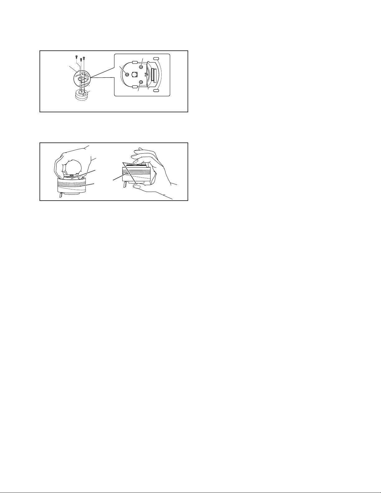
4.4.7.3 Adjustment
(1) Set the main body at test mode.
(2) Press the "SET UP MENU" key of the remote controller three times, and the FDP is displayed "CHECK".
(3) Insert a test disc (VT-501), and press the "PLAY" button of the front panel.
(4) After a few seconds, press the numeric key "6" of the remote controller. Then, the FDP is displays a jitter value.
(5) Turn the adjustment screws on the underside of the traverse mechanism with screw driver until the maximum jitter value is dis-
played on the FDP. (In this model, a bigger jitter value means a better result.)
NOTE:
• Reference values to judge whether the jitter is allowable or not are displayed, instead of actual jitter values.
• Please be sure to perform "all-initialization" and "optim ization adjustment of front end parameter" after adjusting.
Loading mechanism assembly
Screw a
Screw b
1-24 (No.YD001)
FDP (Example)
1241
****
Traverse mechanism assembly
POINT:
Turn the adjustment screws a and b
to the same angle in the right direction.
Screw c
And turn the adjustment screws a and b
to the same angle in the left direction.
Then, turn the screws a and b in either
the right or the left direction to increase
the number of jitter.
Don't turn the adjustment screw c.
Remote controller "6" key-Jitter value
Page 25

SECTION 5
TROUBLESHOOTING
5.1 Manually removing the cassette tape
If you cannot remove the cassette tape which is loaded because
of any electrical or mechanical failures, manually remove it by
taking the following steps.
(1) Unplug the power cord plug from the power outlet.
(2) Refer to the disassembly procedure of the VCR and per-
form the disassembly of the major parts before removing
the mechanism assembly. (See Fig. 5-1a)
Fig.5-1a
Tension arm assembly
Pole base assembly
Pinch roller arm assembly
(3) Unload the pole base assembly by manually turnin g the
gear of the loading motor until the pole base assembly is
hidden behind the cassette lid. In doing so, hold the tape by
the hand to keep the slack away from any grease. (See
Fig.5-1b )
In case of mechanical failures, while keeping the tension arm assembly free from tension, pull out the tape
on the pole base assembly. Take the spring(a) of the
pinch roller arm assembly off the hook, and detach it
from the tape.
(4) Remove the screw (a) of the side frame (L/R).
(5) Hold the slack tape and cassette cover together, lift the
cassette tape, top frame, cassette holder and side frames
(L, R) together from the rear and remove them by dis-engaging the hooks (a) and (b).
Screw(a)
Cassette tape
Hook(a)
Cassette holder
Top frame
Side frame(R)
Screw(a)
Spring(a)
Direction of unloading
Fig.5-1b
Side frame(L)
Hook(b)
Fig.5-1c
(6) Take up the slack of the tape into the cassette. This com-
pletes removal of the cassette tape.
5.2 Manually removing the disk(DVD/CD)
If you cannot remove the disk which is loaded because of any
electrical or mechanical failures, manually remove it by taking the
following steps.
(1) Unplug the power cord plug from the power outlet.
(2) Remove the top cover and front panel assembly.
(Refer to the disassembly procedure and perform the disassembly of the major parts before removing)
(3) Turn the Middle gear (a) by hand to open the disk tray.(See
Fig. 5-2a)
DVD unit
Middle gear (a)
Unloading
Fig.5-2a
(No.YD001)1-25
Page 26

5.3 Emergency display function (VHS SECTION)
This unit saves details of the last two emergencies as the EMG
history and allows the status of the VCR and the mechanism of
each emergency to be shown both on the display and as OSD information.
When using the emergency function, it is required to set the VCR
to the Jig RCU mode.
Jig RCU
[Data transmitting method]
Depress the " " ( 3 ) button
after the data code is set.
CUSTOM CODE
43: A CODE
DATA CODE
INITIAL MODE
Fig.5-3a Jig RCU [PTU94023B]
5.3.1 Displaying the EMG information
The EMG detail of information can be displayed by transmitting
the code "59" from the Jig RCU.
Note:
• The EMG detail information <1><2> show the informa-
tion on the latest EMG.
It becomes “ – – : – – : – –” when there is no latest EMG
record.
0: 00
E: **
1E: **
1: *1
2: *2
3: 34
4: *5
5: *6
6: *7
7: *8
8: *9
9: *10
Normal display
EMG content display (Latest) See 5.3.4
EMG content display (Previous) See 5.3.4
EMG detail information <1> See 5.3.5
[Deck operation mode]
EMG detail information <1> See 5.3.5
[Mechanism operation mode]
EMG detail information <1> See 5.3.5
[Mechanism sensor information and Mechanism mode position]
EMG detail information <2> See 5.3.6
[Type of the cassette tape in use <1>]
EMG detail information <2> See 5.3.6
[Winding position of the cassette tape in use]
EMG detail information <2> See 5.3.6
[Type of the cassette tape in use <2> (Winding area)]
EMG detail information <3> See 5.3.7
[Previous deck operation mode]
EMG detail information <3> See 5.3.7
[The deck operation mode of the one before the last]
EMG detail information <3> See 5.3.7
[The deck operation mode of the one prior to one above]
EMG display of 7 FDP display model
Fig.5-3b
EMG display of FDP display mode
(1) Transmit the code “59” from the Jig RCU.
The FDP shows the EMG content in the form of “E:**:**”.
<Example 1> E : 01
Latest EMG
<Example 2> E : - -
No EMG record
(2) Transmit the code “59” from the Jig RCU again.
The FDP shows the EMG detail information <1> in the form
of “ *1: *2 : 34 ”.
*1 : Deck operation mode at the moment of EMG
*2 : Mechanism operation mode at the moment of EMG
3- : Mechanism sensor information at the moment of EMG
-4 : Mechanism mode position at the moment of EMG
(3) Transmit the code “59” from the Jig RCU once again.
The FDP shows the EMG detail information <2> in the form
of “ *5 : *6 : *7 ”.
*5 : Type of the cassette tape in use <1> .
*6 : Winding posi ti o n of the casse tt e ta pe in use
*7 : Type of the cassette tape in use <2> (Winding area)
(4) Transmit the code “59” from the Jig RCU once again.
The FDP shows the EMG detail information <3> in the form
of “*8 : *9 : *10”.
*8 : Previous deck operation mode at the moment of EMG
*9 : The deck operation mode of the one before the last at
the moment of EMG
*10: The deck operation mode of the one prior to one
above at the moment of EMG
(5) Transmit the code “59” from the Jig RCU once again to re-
set the display.
1-26 (No.YD001)
Page 27

5.3.2 Clearing the EMG history
(1) Display the EMG history.
(2) Transmit the code “36” from the Jig RCU.
(3) Reset the EMG display.
5.3.3 Details of the OSD display in the EMG display mode
During the EMG display, the OSD shows the data on the deck
mode, etc. The details of the display contents are as follows.
Notes:
• The display is variable depending on the part No. of the
System Control microcomputer (IC3001) built into the
VCR. In the following, refer to the figure carrying the
same two characters as the top two character s of the
part number of your IC.
• The sensor information in the OSD display contents is
partially different from the mechanism sensor information in EMG detail information <1>.
[For MN* only]
AA BB CC DD EE
FF GG HH I I J J
KK LL MM NN OO
PP QQ RR SS TT
UU VV WW XX YY
AA : Deck operation mode (See EMG detail information <1>.)
BB : Mechanism operation mode
(See EMG detail of information <1>.)
CC : Mechanism transition flag
DD : Capstan motor control status
EE : Loading motor control status
FF : Sensor information (See sensor information details.)
GG : Capstan motor speed
HH : Key code (JVC code)
I I : Supply reel winding diameter data higher 8 bits.
JJ : Supply reel winding diameter data lower 8 bits.
KK : Mechanism sensor information & mechanism mode posi-
tion(See EMG detail of information <1>.)
LL : Tape speed data higher 8 bits.
MM : Tape speed data lower 8 bits.
NN : Cassette tape type <2> higher 8 bits.
(See EMG detail of information <2>.)
OO : Cassette tape type <2> lower 8 bits.
(See EMG detail of information <2>.)
PP : General data display area
YY : General data display area
*FF:Sensor information details
<Display>
** h
********
Encoder data
(See Mechanism mode sequence.)
Cassette tab present = 1
Cassette tab broken = 0
Cassette absent = 1
Cassette present = 0
Start sensor
End sensor
[For *HD only]
AA BB CC
DD EE FF
GGGG HHHH
I I JJJJ
KKKK LLLL MMMM
ROM No.
AA : Key code (JVC code)
BB : Deck operation mode(See EMG detail information
<1>.)
CC : Mechanism operation mode (See EMG detail informa-
tion <1>.)
DD : Sensor information (See sensor information details.)
EE : Capstan motor speed (Search, double speed)
FF : Tracking value
GGGG : Cassette tape type <2>, 16 bits.
(See EMG detail information <2>.)
HHHH : Supply reel winding diameter data
I I : Capstan motor speed (FF/REW, double speed)
JJJJ : Tape speed data, lower 8 bits.
KKKK : General data display area
LLLL : General data display area
MMMM : General data display area
*DD:Sensor information details
<Display>
** h
********
Encoder data
(See Mechanism mode sequence.)
Remote pause
End sensor
Start sensor
Cassette tab present = 1
Cassette tab broken = 0
[For both MN*/HD*]
Mechanism mode sequence
Mechanism mode - Encoder data
LSA
12345
1110
GND
LSA
LSB
LSC
LSD
No. Position Encoder data
21
Encoder output = Low
or
Trerminal - GND = SHORT
1
EJECT 0 h = 0000
2
EJECT1 1 h = 0001
3
EJECT2 2 h = 0010
4
ULSTOP 3 h = 0011
5
UPPER 4 h = 0100
6
ONSTOP(PLAY) 5 h = 0101
7
FWD/SS 6 h = 0110
8
REV/SS 7 h = 0111
9
OFFSTOP 8 h = 1000
10
FFREW-BRAKE 9 h = 1001
FFREW A h = 1010
11
MIDDLE F h = 1111
12
543
Encoder output = High
Trerminal - GND = OPEN
9876
or
LSB
LSD
LSC
(No.YD001)1-27
Page 28

5.3.4 EMG content description
Note:
EMG contents “E08/E09” are for the model with Dynamic Drum (DD).
FDP CONTENT CAUSE
E01: Loading EMG
E02:
Unloading EMG
E03: Take Up Reel
Pulse EMG
E04: Drum FG EMG
E05: Cassette Eject
EMG
E06: Capstan FG
EMG
E07: SW Power
Short-Circuit
EMG
E08:
DD Initialized
(Absolute
Position
Sensor) EMG
E09: DD FG EMG
E0A: Supply Reel
Pulse EMG
EU1:
Head clog warning
history
If the mechanism mode does not change to the next mode within 4 seconds after the loading motor starts rotating in the loading direction, while
the mechanism is in the after-loading position (with the tape up against
the pole base), [E:01] is identified and the power is switched OFF.
However, if the tape loading is not completed within 4 seconds after
the loading motor starts rotating in the loading direction, the tape is
simply unloaded and ejected. No EMG data is recorded in this case.
When the mechanism mode cannot be changed to another mode
even when the loading motor has rotated for more than 4 seconds in the unloading direction, [E:02] is identified and the power
is turned off.
When the falling edje of the take-up reel pulse has not been generated for more than 4 seconds in the capstan rotating mode,
[E:03] is identified, the pinch rollers are turned off and stopped,
and the power is turned off. In this case, however, the mechanism should be in position after tape loading. Note that the reel
EMG is not detected during Slow/Frame advance operations.
When the drum FG pulse has not been input for more than 3 seconds in the drum rotating mode, [E:04] is identified, the pinch rollers are turned off and stopped, and the power is turned off.
If the cassette does not reach the eject position within about 0.7
seconds after the cassette housing has started the cassette ejection operation, [E:05] is identified, the drive direction is reversed
to load the tape, the mode is switched to STOP mode with the
pinch roller OFF, and the power is switched OFF.
During the cassette insertion process, the drive direction is reversed
and the cassette is ejected if the tape is not up against the pole
base within about 3 seconds after the start of the cassette pullingin operation. If the cassette does not reach the eject position within
about 0.7 seconds after the drive mode reversal operation, [E:05]
is identified and the power is switched OFF immediately.
When the capstan FG pulse has not been generated for more
than 1 second in the capstan rotating mode, [E:06] is identified,
the pinch rollers are turned off and stopped, and the power is
turned off.However, the capstan EMG is not detected in SLOW/
STILL modes.
Note that, if the part number of the System Control IC begins with
"MN" or "M3", the capstan EMG is not detected even during the
FF/REW operation.
When short-circuiting of the SW power supply with GND has lasted
for 0.5 second or more, [E:07] is identified, all the motors are
stopped and the power is turned off.
When DD tilting does not complete in 4 seconds, [E:08] is identified, the tilt motor is stopped and the power is turned off.
When the DD FG pulse is not generated within 2.5 seconds, [E:09]
is identified, the tilt motor is stopped and the power is turned off.
When the falling edge of the supply reel pulse has not been generated for more than 10 seconds in the capstan rotating mode,
[E:0A] is identified and the cassette is ejected (but the power is
not turned off). In this case, however, the mechanism should be
in the position after tape loading (with the tape up against the pole
base). Also note that the reel EMG is not detected during Slow/
Frame advance operations.
Presupposing the presence of the control pulse output in the PLAY mode, when the value obtained by mixing the two V.FM output channels (without regard
to the A.FM output) has remained below a certain threshold level for more than 10 seconds, [E:U1] is identified and recorded in the emergency history.
During the period in which the head clog is detected, the FDP shows "U:01" and the OSD repeats the "3 seconds of warning display" and the "7 seconds of
noise picture display" alternately.
EMG code : "E:C1" or "E:U1" / FDP : "U:01" / OSD : "Try cleaning tape." or "Use cleaning cassette."
The head clog warning is reset when the above-mentioned threshold has been exceeded for more than 2 seconds or the mode is changed to another mode
than PLAY.
1. The mechanism is locked in the middle of the mode transition during a tape loading operation.
2.
The mechanism overruns during the tape loading operation because the SYSCON cannot recognize
the mechanism mode normally. This problem is due to a cause such as a rotary encoder failure.
3.
Power is not supplied to the loading MDA. (M12V/Vcc/Vref/ICP are disconnected in the middle.)
1.
The mechanism is locked in the middle of mode transition.
2.
Without an eject signal being sent from the SYSCON, unloading is attempted (i.e. Ejection is attempted
while the tape is still inside the mechanism.) because the SYSCON cannot recognize the mechanism
mode normally. This is due to a cause such as a rotary encoder failure. (Mechanism position:
UPPER)
3.
Power is not supplied to the loading MDA. (M12V/Vcc/Vref/ICP are disconnected in the middle.)
1.
The take-up reel pulse is not generated in the FWD transport modes (PLAY/FWD SEARCH/FF,
etc.) because;
1) The idler gear is not meshed with the take-up reel gear because the mechanism mal-functions for
some reason.
2)
The idler gear is meshed with the take-up reel gear, but incapable of winding due to too large
mechanical load (abnormal tension);
3) The reel is rotating normally but an FG pulse is not generated due to the take-up reel sensor failure.
2.
The supply reel pulse is not generated in the REV transport modes (REV SEARCH/REW, etc.)
because;
1) The idler gear is not meshed with the supply reel gear because the mechanism mal-functions for
some reason.
2) The idler gear is meshed with the supply reel gear, but incapable of winding due to too large a
mechanical load (abnormal tension);
3) The reel rotates normally but the FG pulse is not generated due to a supply reel sensor failure.
3.
Power(SW5V) is not supplied to the reel sensor on the tape winding side.
1.
The drum could not start or the drum rotation has stopped due to too large a load on the tape,
because;
1) The tape tension is abnormally high;
2) The tape is damaged or a foreign object (grease, etc.) adheres to the tape.
2.
The drum FG pulse did not reach the System controller CPU because;
1) The signal circuit is disconnected in the middle;
2) The FG pulse generator (hall device) of the drum is faulty.
3.
The drum control voltage (DRUM CTL V) is not supplied to the MDA.
4.
Power (M12V) is not supplied to the drum MDA.
1.
The cassette cannot be ejected due to a failure in the drive mechanism of the housing.
2.
When the housing load increases during ejection, the loading motor is stopped because of lack of
headroom in its drive torque.
Housing load increasing factors: Temperature environment (low temperature, etc.), mechanism
wear or failure.
3.
The sensor/switch for detecting the end of ejection are not functioning normally.
4.
The loading motor drive voltage is lower than specified or power (M12V) is not supplied to the
motor (MDA).
5.
When the user attempted to eject a cassette, a foreign object (or perhaps the user's hand) was
caught in the opening of the housing.
1.
The capstan could not start or the capstan rotation has stopped due to too large a load on the tape,
because;
1) The tape tension is abnormally high (mechanical lock);
2) The tape is damaged or a foreign object (grease, etc.) is adhered to the tape (occurrence of tape
entangling, etc.).
2.
The capstan FG pulse did not reach the System controller CPU because;
1) The signal circuit is disconnected in the middle;
2) The FG pulse generator (MR device) of the capstans is faulty.
3.
The capstan control voltage (CAPSTAN CTL V) is not supplied to the MDA.
4.
Power (M12V, SW5V) are not supplied to the capstan MDA.
1.
The SW 5 V power supply circuit is shorted with GND.
2.
The SW 12 V power supply circuit is shorted with GND.
1. The absolute value sensor is defective. (The soldered parts have separated.)
2. The pull-up resistor at the absolute sensor output is defective. (The soldered parts have separated.)
3. Contact failure or soldering failure of the pins of the connector (board-to-board) to the absolute value
sensor.
4.
The absolute value sensor data is not sent to the System Controller CPU.
1. The FG sensor is defective. (The soldered parts have separated.)
2. The pull-up resistor at the FG sensor output is defective. (The soldered parts have separated.)
3. Contact failure or soldering failure of the pins of the connector (board-to-board) to the FG sensor.
4. The power (5V) to the sensor is not supplied. (Connection failure/soldering failure)
5. The FG pulse is not sent to the System Controller CPU.
6.
The tilt motor is defective. (The soldered parts have separated.)
7. The drive power to the tilt motor is not supplied. (Connection failure/soldering failure)
8. The tilt motor drive MDA - IC is defective.
9. Auto-recovery of the DD tilting cannot take place due to overrun.
The supply reel pulse is not generated in the FWD transport mode (PLAY/FWD SEARCH/FF,
1.
etc.) because;
1) PLAY/FWD or SEARCH/FF is started while the tape in the inserted cassette is cut in the middle;
2) A mechanical factor caused tape slack inside and outside the supply reel side of the cassette shell.
In this case, the supply reel will not rotate until the tape slack is removed by the FWD transport,
so the pulse is not generated until then;
3) The reel is rotating normally but the FG pulse is not generated due to a supply reel sensor failure.
2.
The take-up reel pulse is not generated in the REV transport mode (REV SEARCH/REW, etc.).
1) REV SEARCH/REW is started when the tape in the inserted cassette has been cut in the middle;
2) A mechanical factor caused tape slack inside and outside the take-up reel side of the cassette
shell. In this case, the take up will not rotate until the tape slack is removed by the REV transport,
so the pulse will not be generated until that time;
3) The reel is rotating normally but the FG pulse is not generated due to a take-up reel sensor failure.
3.
The power (SW 5V) to a reel sensor is not supplied.
1-28 (No.YD001)
Page 29

5.3.5 EMG detail information <1>
The status (electrical operation mode) of the VCR and the status
(mechanism operation mode/sensor information) of the mechanism in the latest EMG can be confirmed based on the figure in
EMG detail information <1> .
[FDP/OSD display] *1 : *2 : 34
*1 : Deck operation mode at the moment of EMG
*2 : Mechanism operation mode at the moment of EMG
3- : Mechanism sensor information at the moment of EMG
-4 : Mechanism mode position at the moment of EMG
Note:
• For EMG detailed information <1>, the content of the
code that is shown on the display (or OSD) differs depending on the parts number of the system control microprocessor (IC3001) of the VCR. The system control
microprocessor parts number starts with two letters, refer these to the corresponding table.
*1 : Deck operation mode
[Common table of MN* and HD]
Display
MN* HD*
00 - Mechanism being initialized
01 00 STOP with pinch roller pressure off (or tape present with P.OFF)
02 01 STOP with pinch roller pressure on
03 - POWER OFF as a result of EMG
04 04 PLAY (Normal playback)
0C 0E REC
10 11 Cassette ejected
20 22 FF
21 - Tape fully loaded, START sensor ON, short FF
22 -
24 26 FWD SEARCH (variable speed) including x2-speed
2C 2E INSERT REC
40 43 REW
42 - Cassette identification REV SEARCH before transition to REW
44 47 REV SEARCH (variable speed)
4C 4C AUDIO DUB
6C 6E INSERT REC (VIDEO + AUDIO)
84 84 FWD STILL / SLOW
85 85 REV STILL / SLOW
8C 8F REC PAUSE
8D - Back spacing
8E - Forward spacing (FWD transport mode with BEST function)
AC AF INSERT REC PAUSE
AD - INSERT REC back spacing
CC CD AUDIO DUB PAUSE
CD - AUDIO DUB back spacing
EC EF INSERT REC (VIDEO + AUDIO) PAUSE
ED - INSERT REC (VIDEO + AUDIO) back spacing
Cassette identification FWD SEARCH before transition to FF
(SPx7-speed)
(SPx7-speed)
Deck operation mode
*2 : Mechanism operation mode
[Table of MN*]
Display
00 Command standby (No command to be executed)
01 Immediate Power OFF after EMG occurrence
02 Loading from an intermediate position during mechanism initialization
03 Unloading due to EMG occurrence during mechanism initialization
04 Ejecting cassette (ULSTOP to EJECT)
05 Inserting cassette (EJECT to ULSTOP)
06 Loading tape (ULSTOP to PLAY)
07 Unloading tape (PLAY to ULSTOP)
08 Transition from pinch roller ON to STOP
09 Transition from pinch roller OFF to STOP (PLAY to OFFSTOP)
0A Transition from pinch roller OFF to STOP at power OFF
0B Transition from pinch roller ON to STOP at power ON
0C Transition to PLAY
0D Transition to Search FF
0E Transition to REC
0F Transition to FWD STILL/SLOW
10 Transition to REV STILL/SLOW
11 Transition to Search REV
12 Transition from FF/REW to STOP
13 Transition to FF
14 Transition to REW
15 Tape end detection processing during loading
16 Short FWD/REV at tape sensor ON during unloading
17 Transition to FF/REW brake mode
Mechanism operation mode
[Table of HD*]
Display
00 STOP with pinch roller pressure off
01 STOP with pinch roller pressure on
02 U/L STOP (or tape being loaded)
04 PLAY (Normal playback)
05 PLAY (x1-speed playback using JOG)
0E REC
11 Cassette ejected
22 FF
26 FWD SEARCH (variable speed) including x2-speed
2E INSERT REC
43 REW
47 REV SEARCH
4C AUDIO DUB
6E INSERT REC (VIDEO + AUDIO)
84 FWD STILL/SLOW
85 REV STILL/SLOW
8F REC PAUSE
AF INSERT REC PAUSE
C7 REV SEARCH (x1-speed reverse playback using JOG)
CD AUDIO DUB PAUSE
EF INSERT REC (VIDEO + AUDIO) PAUSE
F0 Mechanism being initialized
F1 POWER OFF as a result of EMG
F2 Cassette being inserted
F3 Cassette being ejected
F4 Transition from STOP with pinch roller pressure on to STOP with pinch
roller pressure off
F5 Transition from STOP with pinch roller pressure on to PLAY
F6 Transition from STOP with pinch roller pressure on to REC
F7 Cassette type detection SEARCH before FF/REW is being executed
F8 Tape being unloaded
F9 Transition from STOP with pinch roller pressure off to STOP with pinch
roller pressure on
FA Transition from STOP with pinch roller pressure off to FF/REW
FB Transition from STOP with pinch roller pressure off to REC.P (T.REC,etc.)
FC Transition from STOP with pinch roller pressure off to cassette type
detection SEARCH
FD Short REV being executed after END sensor on during unloading
FE Tension loosening being executed after tape loading (STOP with pinch
roller pressure on)
FF Tape being unloaded
Mechanism operation mode
(No.YD001)1-29
Page 30

3- : Mechanism sensor information
[Common table of MN* and HD*]
Display
REC safety SW
0- Tab broken ON ON ON
1- Tab broken ON
2- Tab broken ON
3- Tab broken ON OFF
4- Tab present ON
5- Tab present
6- Tab present OFF
7- Tab present OFF
8- Tab broken ON ON
9- Tab broken ON
A- Tab broken
B- Tab broken OFF
C- Tab present ON
D- Tab present
E- Tab present OFF
F- Tab present OFF
Tab broken = 0 Sensor ON = 0 Sensor ON = 0
Tab present = 1 sensor OFF = 1 Sensor OFF = 1
Mechanism sensor informatio n
Start sensor End sensor
ON
OFF
OFF
OFF
ON
ON
OFF
OFF
ON
OFF
OFF
ON
OFF
ON
OFF
OFF OFF
Mechansim
position sensor
OFF
ON
OFF
ON
OFF
ON
OFF
ON
OFF
ON
OFF
ON
OFF
ON
-4 : Mechanism mode position
[Common table of MN* and HD*]
Mechanism
sensor
information
Display
Deck operation mode
-0 Not established
-1 EJECT EJECT position
-2 EJECT-EJECT1 Intermodal position
-3 EJECT1 EJECT1 position
-4 EJECT1-EJECT2 Intermodal position
-5 EJECT2 EJECT2 position
-6 EJECT2-ULSTOP Intermodal position
Even number
(0, 2, 4, 6, 8,
A, C, E)
-7 ULSTOP ULSTOP position
-8 ULSTOP-UPPER Intermodal position
-9 UPPER Loading (unloading) tape
-A UPPER-ONSTOP Intermodal position
-B ONSTOP PLAY position
-C PLAY-FWD/SS Intermodal position
-D FWD/SS
FWD (FWD Still/Slow) position
-E FWD/SS-REV Intermodal position
-F REV
REV (REV Still/Slow) position
-0 REV-OFFSTOP Intermodal position
-1 OFFSTOP Pinch roller OFF position
Odd number
(1, 3, 5, 7, 9,
B, D, F)
-2
OFFSTOP-FFREWB
Intermodal position
-3 FFREWB FF/REW Brake position
-4 FFREWB-FFREW Intermodal position
-5 FFREW FF/REW position
5.3.6 EMG detail information <2>
The type of the cassette tape and the cassette tape winding position can be confirmed based on the figure in EMG detail information <2> .
Note:
• EMG detail information <2> is the reference information
stored using the remaining tape detection function of
the cassette tape. As a result, it may not identify ca ssette correctly when a special cassette tape is used or
when the tape has variable thickness.
*5 : Cassette tape type <1>
Display Cassette tape type <1>
00 Cassette type not identified
16
Large reel/small reel (T-0 to T-15/T-130 to T-210) not classified
82 Small reel, thick tape (T-120) identified/thin tape (T-140) identified
84 Large reel (T-0 to T-60) identified
92
Small reel, thick tape (T-130) identified/thin tape (T-160 to T-210) identified
93
Small reel, thick tape/C cassette (T-0 to T-100/C cassette) not classified
C3
Small reel, thick tape/C cassette (T-0 to T-100/C cassette) being classified
D3
Small reel, thick tape/C cassette (T-0 to T-100/C cassette) being classified
E1 C cassette, thick tape (TC-10 to TC-20) identified
E2 Small reel, thick tape (T-0 to T-100) identified
E9 C cassette, thin tape (TC-30 to TC-40) identified
F1
C cassette, thick tape/thin tape (TC-10 to TC-40) not classified
Notes:
• Cassette tape type <1> is identified a few times during
mode transition and the identification count is variable
depending on the cassette tape type . If an EMG occ urs
in the middle of identification, the cassette tape type
may not be able to be identified.
• If other value than those listed in the above table is dis-
played, the cassette tape type is not identified.
*6 : Cassette tape winding position
The cassette tape winding position at the moment of EMG is displayed by dividing the entire tape (from the beginning to the end)
in 21 sections using a hex number from “00” to “14”.
00 : End of winding
14 : Beginning of winding
FF : Tape position not identified
*7 : Cassette tape type <2> (Winding area)
Display
00
04 - 08
05 - 06
05 - 0C
06 - 0C
06 - 0C
07 - 08
09 - 0B
0C - 0D
0D - 0F
0E - 10
10 - 12
10 - 13
11 - 14
12 - 14
13 - 14
13 - 14
13 - 14
13 - 14
15 - 16
16 - 17
17 - 18
19 - 1B
Cassette tape type <2>
Cassette type not identified
C cassette, thick tape TC-10
Small reel, thick tape T-20
C cassette, thick tape TC-20P
C cassette, thin tape TC-40
C cassette, thin tape TC-30
Small reel, thick tape T-40
Small reel, thick tape T-60
Small reel, thick tape T-80(DF-160)
Small reel, thick tape T-90(DF-180)
Small reel, thick tape T-100
Small reel, thin tape T-140
Small reel, thick tape T-120(DF-240)
Small reel, thick tape T-130
Small reel, thin tape T-160
Small reel, thin tape T-210(DF-420)
Small reel, thin tape T-180(DF-360)
Small reel, thin tape T-168
Small reel, thick tape DF-300
Large reel T-20
Large reel T-30
Large reel T-40
Large reel T-60
(Reference) Word data
(Beginning) (End)
(0497 - 0506)(0732 - 0858)
(05A9 - 0661)
(0599 - 05FF)(0AA1 - 0C07)
(0623 - 063D) (0C41 - 0CC3)
(0611 - 0638)(0C0C - 0CB2)
(07CC - 08E5)
(09FD - 0B78)
(0C20 - 0DFC)
(0D31 - 0F3E)
(0E43 - 107F)
(10E1 - 120C)
(1073 - 1313)
(1185 - 1429)
(12D3 - 141F)
(1373 - 14C3)
(1357 - 14C0)
(1395 - 14EE)
(13A8 - 14CE)
(1536 - 1618)
(1647 - 175A)
(1759 - 189C)
(1989 - 1B2F)
Note:
• The values of cassette tape type <2> in the above table
are typical values with representative cassette tapes.
5.3.7 EMG detail information <3>
Three deck operation modes preceding the deck operation mode
in which the EMG occurs may be confirmed based on the figures
in the EMG information detail <3>. For the contents of the displayed information, see the table "Deck operation mode" in section "5.3.5 EMG detail information <1>".
1-30 (No.YD001)
Page 31

5.4 Troubleshooting (DVD SECTION)
Press OPEN
/CLOSE key
Is tray
operation
Confirmation of tray drive circuit
N
and circuit in surrounding
correct?
Y
Is the traverse moving
along the innermost
N
perimeter for SW detection?
Y
"NO DISC" message appears
Y
immediately after vertical
movement of the pick-up lens
N
The state that DISC does not rotate continues for
several seconds, and becomes NO DISC or an
error display afterwards.
The rotation of DISC becomes high-speed and
abnormal, and becomes NO DISC or an error
display afterwards.
N
Is focus retraction OK?
FE
OFF
Even when it retracts
correctly, if it is out of focus
and makes repeated retries
with a clicking sound, it is
in error.
ON
See "5.5.4 Focus ON error"
N
in "Check points for
individual errors"
Y
Is tracking retraction OK?
See "5.5.3 Traverse movement error"
in "Check points for individual errors"
See "5.5.2 Disk detection, distinction error"
in "Check points for individual errors"
Y
See "5.5.1 Spindle startup error"
in "Check points for individual errors"
A
Is the inter-layer jump OK?
FE
LO LI
Two layers of DVD only.
N
5.5.8 Inter-layer
jump error
Y
TE
OFF
If TE waveform reappears
or fails to converge after the
TE retraction, it is in error.
ON
Y
Is the spindle servo
locked correctly?
Is the RF OUT waveform
locked correctly?
Y
A
See "5.5.5 Tracking ON error"
N
in "Check points for
individual errors"
See "5.5.6 Spindle CLV error"
N
in "Check points for
individual errors"
Fig.5-4a
Has the disc information
been collected?
Stop will result
Y
Is playback
N
possible?
Y
OK !
N
5.5.7 Address read
error
Check 5.5.9, 5.5.10, 5.5.11, and
5.5.12 items in "Check points
for individual errors"
(No.YD001)1-31
Page 32

5.5 Check points for each error (DVD SECTION)
5.5.1 Spindle start error
(1) Defective spindle motor
• Are there several ohms resistance between each pin of CN201
(The power supply is turned off and measured.)
• Is the sign wave of about 100mVp-p in the voltage had from each terminal?
[ CN201"10"(H1+),"11"(H1-),"7"(H2+),"8"(H2-),"5"(H3+),"6"(H3-) ]
(2) Defective spindle motor driver (IC251
• Has motor drive voltage of a sine wave or a rectangular wave gone out to each terminal(SM1~3)
of CN201"1,2,3" and IC251"2,4,7"?
• Is FG pulse output from the terminal of IC251
• Is it "L(about 0.9V)" while terminal of IC251
(3) Has the control signal come from servo IC or the microcomputer?
• Is it "L" while the terminal of IC251
Is it "H" while the terminal of IC251
• Is the control signal input to the terminal of IC251
(changes from VHALF voltage while the motor is working.)
• Is the VHALF voltage input to the terminal of IC251"21"(ECR)?
(4) Is the FG signal input to the servo IC?
• Is FG pulse input to the terminal of IC301
5.5.2 Disc Detection, Distinction error (no disc, no RFENV)
• Laser is defective.
• Front End Processor is defective (IC101
• APC circuit is defective. --- Q101,Q102.
• Pattern is defective. --- Lines for CN101
• IC101 --- For signal from IC101 to IC301, is signal output from IC101 "20" (ASOUT) and IC101 "41"(RFENV) and IC101 "22"
(FEOUT)?
)
"24"(FG) according to the rotation of the motor?
"15"(VH) is rotating the motor?
"18"(SBRK) is operating?
"23"(/SPMUTE) is operating?
"22"(EC)?
"69"(FG) according to the rotation of the motor?
).
- All patterns which relate to pick-up and patterns between IC101
"1-2","2-3","1-3"?
5.5.3 Traverse movement NG
(1) Defective traverse driver
• Has the voltage come between terminal of CN101 "2" and "4" ?
(2) Defective BTL driver (IC201)
• Has the motor drive voltage gone out to IC201
(3) Has the control signal come from servo IC or the microcomputer?
• Is it "H" while the terminal of IC201
• TRSDRV Is the signal input? (IC301
(4) TRVSW is the signal input from microcomputer? (IC301
5.5.4 Focus ON NG
• Is FE output ? --- Pattern, IC101
• Is FODRV signal sent ? (R209) --- Pattern, IC301 "115"
• Is driving voltage sent ? IC201
• Mechanical unit is defective.
5.5.5 Tracking ON NG
• When the tracking loop cannot be drawn in, TE shape of waves does not settle.
• Mechanical unit is defective.
Because the self adjustment cannot be normally adjusted, the thing which cannot be normally drawn in is thought.
• Periphery of driver (IC201
Constant or IC it self is defective.
• Servo IC (IC301)
When improperly adjusted due to defective IC.
)
"9"(STBY1) ?
"67")
"13", "14" --- If NG, pattern, driver, mechanical unit .
"17" or "18"?
"56")
1-32 (No.YD001)
Page 33

5.5.6 Spindle CLV NG
• IC101 -- "30"(ARF-), "31(ARF+).
• Does not the input or the output of driver's spindle signal do the grip?
• Has the tracking been turned on?
• Spindle motor and driver is defective.
• Additionally, "IC101
5.5.7 Address read NG
• Besides, the undermentioned cause is thought though specific of the cause is difficult because various factors are thought.
Mechanism is defective. (jitter)
IC301
The disc is dirty or the wound has adhered.
5.5.8 Between layers jump NG (double-layer disc only)
Mechanism defective
Defect of driver's IC(IC201
Defect of servo control IC(IC301)
5.5.9 Neither picture nor sound is output
(1) It is not possible search
• Has the tracking been turned on?
• To " Tracking ON NG" in "Check points for each error" when the tracking is not normal.
• Is the feed operation normal?
To " traverse movement NG" in "Check points for each error" when it is not normal.Are not there caught of the feeding mechanism etc?
and IC301" and "Mechanism is defective(jitter)", etc. are thought.
)
5.5.10 Picture is distorted or abnormal sound occurs at intervals of several seconds.
Is the feed operation normal?
Are not there caught of the feeding mechanism etc?
5.5.11 Others
• The image is sometimes blocked, and the image stops.
• The image is blocked when going to outer though it is normal in suroundings in the disk and the stopping sympton increases.
There is a possibility with bad jitter value for such a symptom.
5.5.12 CD During normal playback operation
(1) Is TOC reading normal?
• Displays total time for CD-DA.
• Shifts to double-speed mode for V-CD
(2) Is playback afterwards possible?
(3) When can not do a normal playback
• --:-- is displayed during FL search.
According to [It is not possible to search ] for DVD, check the feed and tracking systems.
• No sound is output although the time is displayed.(CA-DA)
DAC, etc, other than servo.
• The passage of time is not stable, or picture is abnormal.(V-CD)
• The wound of the disc and dirt are confirmed.
(No.YD001)1-33
Page 34

JVC SERVICE & ENGINEERING COMPANY OF AMERICA
DIVISION OF JVC AMERICAS CORP.
www.jvcservice.com(US Only)
JVC CANADA INC.
Head office : 21 Finchdene Square Scarborough, Ontario M1X 1A7 (416)293-1311
(No.YD001)
Printed in Japan
WPC
 Loading...