

Page 1
SERVICE MANUAL
DVD PLAYER & VIDEO CASSETTE RECORDER
YD00820043
HR-XVC22UC, HR-XVC23UC,
HR-XVC26US, HR-XVC27UC,
HR-XVC27US
HR-XVC22UC, HR-XVC23UC, HR-XVC26US, HR-XVC27UC, HR-XVC27US [D3PV0]
For disassembling and assembling of MECHANISM ASSEMBLY, refer to the SERVICE MANUAL No.86700(MECHANISM ASSEMBLY).
TABLE OF CONTENTS
1 PRECAUTION. . . . . . . . . . . . . . . . . . . . . . . . . . . . . . . . . . . . . . . . . . . . . . . . . . . . . . . . . . . . . . . . . . . . . . . . . 1-3
2 SPECIFIC SERVICE INSTRUCTIONS. . . . . . . . . . . . . . . . . . . . . . . . . . . . . . . . . . . . . . . . . . . . . . . . . . . . . . 1-7
3 DISASSEMBLY . . . . . . . . . . . . . . . . . . . . . . . . . . . . . . . . . . . . . . . . . . . . . . . . . . . . . . . . . . . . . . . . . . . . . . . 1-9
4 ADJUSTMENT . . . . . . . . . . . . . . . . . . . . . . . . . . . . . . . . . . . . . . . . . . . . . . . . . . . . . . . . . . . . . . . . . . . . . . . 1-15
5 TROUBLESHOOTING . . . . . . . . . . . . . . . . . . . . . . . . . . . . . . . . . . . . . . . . . . . . . . . . . . . . . . . . . . . . . . . . . 1-21
COPYRIGHT © 2004 VICTOR COMPANY OF JAPAN, LIMITED
No.YD008
2004/3
Page 2

SPECIFICATION
HR-XVC22UC, HR-XVC23UC HR-XVC26US ,HR-XVC27UC, HR-XVC27US
GENERAL
Power requirement AC 120 V, 60 Hz
Power consumption
Power on 22 W
Power off
Temperature
Operating 5
Storage -20°C to 60°C (-4°F to140°F)
Operating position Horizontal only
Dimensions (W × H × D) 435 mm x 93 mm x 272 mm
Weight
Format VHS NTSC standard
Maximum recording time
(SP) 210 min. with ST-210 video cassette
(EP) 630 min. with ST-210 video cassette
VIDEO/AUDIO (VCR deck)
Signal system NTSC color signal and EIA monochrome signal, 525 lines/60 fields
Recording system DA4 (Double Azimuth) head helical scan system
Signal-to-noise ratio 45 dB
Horizontal resolution 230 lines
Frequency range 70 Hz to 10,000 Hz (Normal audio) 20 Hz to 20,000 Hz (Hi-Fi audio)
Input/Output RCA connectors: IN × 1, OUT × 1
VIDEO/AUDIO (DVD deck)
Signal system NTSC
Applicable disc DVD (12 cm, 8 cm), CD (12 cm, 8 cm)
Audio characteristics DVD:4 Hz - 22 KHz
Frequency response CD:4 Hz - 20 KHz
S/N Ratio 90 dB
Harmonic distortion 0.1%
Wow and flutter Below Measurable Level
Dynamic range 90 dB
Output
Component-Y (RCA) 1.0 Vp-p/75 Ω
Component-PB/PR (RCA) 0.7 Vp-p/75 Ω
Audio (RCA) 2 Vrms, 1 KΩ
Digital Audio (COAXIAL) 0.5 Vp-p/75 Ω
TUNER
Tuning system Frequency synthesized tuner
Channel coverage VHF: Channels 2 - 13, UHF: Channels 14 - 69, CATV: 113 Channels
RF output - Channel 3 or 4 (switchable; preset to Channel 3 when
TIMER
Clock reference Quartz
Program capacity 1-year programmable timer/8 programs
Memory backup time Approx. 5 seconds
ACCESSORIES
Provided accessories RF cable, Audio/Video cable, Infrared remote control unit,
"AA" battery × 2
°C to 40°C (41°F to 104°F)
• Specifications shown are for SP mode unless otherwise specified.
• E.& O.E. Design and specifications subject to change without notice.
• Manufactured under license from Dolby Laboratories. "Dolby" and the double-D symbol are trademarks of Dolby Laboratories.
• "DTS" and "DTS 2.0 + Digital Out" are trademarks of Digital Theater Systems, Inc.
2.0 W
4.1 kg
shipped) 75 Ω, unbalanced
RF cable, Infrared remote control unit, "AA" battery × 2
1-2 (No.YD008)
Page 3
SECTION 1
r
e
PRECAUTION
1.1 SAFTY PRECAUTIONS
Prior to shipment from the factory, JVC products are strictly inspected to conform with the recognized product safety and electrical codes of the countries in which they are to be
sold.However,in order to maintain such compliance, it is equally
important to implement the following precautions when a set is
being serviced.
1.1.1 Precautions during Servicing
(1) Locations requiring special cauti on are denoted by labels
and inscriptions on the cabinet, chassis and certain parts of
the product.When performing service, be sure to read and
comply with these and other cautionary notices appearing
in the operation and service manuals.
(2) Parts identified by the symbol and shaded ( ) parts
are critical for safety.
Replace only with specified part numbers.
NOTE :
Parts in this category also include those specified to
comply with X-ray emission standards for products
using cathode ray tubes and those specified for
compliance with various regulations regarding spurious radiation emission.
(3) Fuse replacement caution notice.
Caution for continued protection against fire hazard.
Replace only with same type and rated fuse(s) as specified.
(4) Use specified internal wiring. Note especially:
• Wires covered with PVC tubing
• Double insulated wires
• High voltage leads
(5) Use specified insulating materials for hazardous live parts.
Note especially:
• Insulation Tape
• PVC tubing
•Spacers
• Insulation sheets for transistors
•Barrier
(6) When replacing AC primary side compon ents (transformers,
power cords, noise blocking capacitors, etc.) wrap ends of
wires securely about the terminals before soldering.
Consequently, when servicing these products, replace the
cathode ray tubes and other parts with only the specified
parts. Under no circumstances attempt to modify these circuits.Unauthorized modification can increase the high voltage value and cause X-ray emission from the cathode ray
tube.
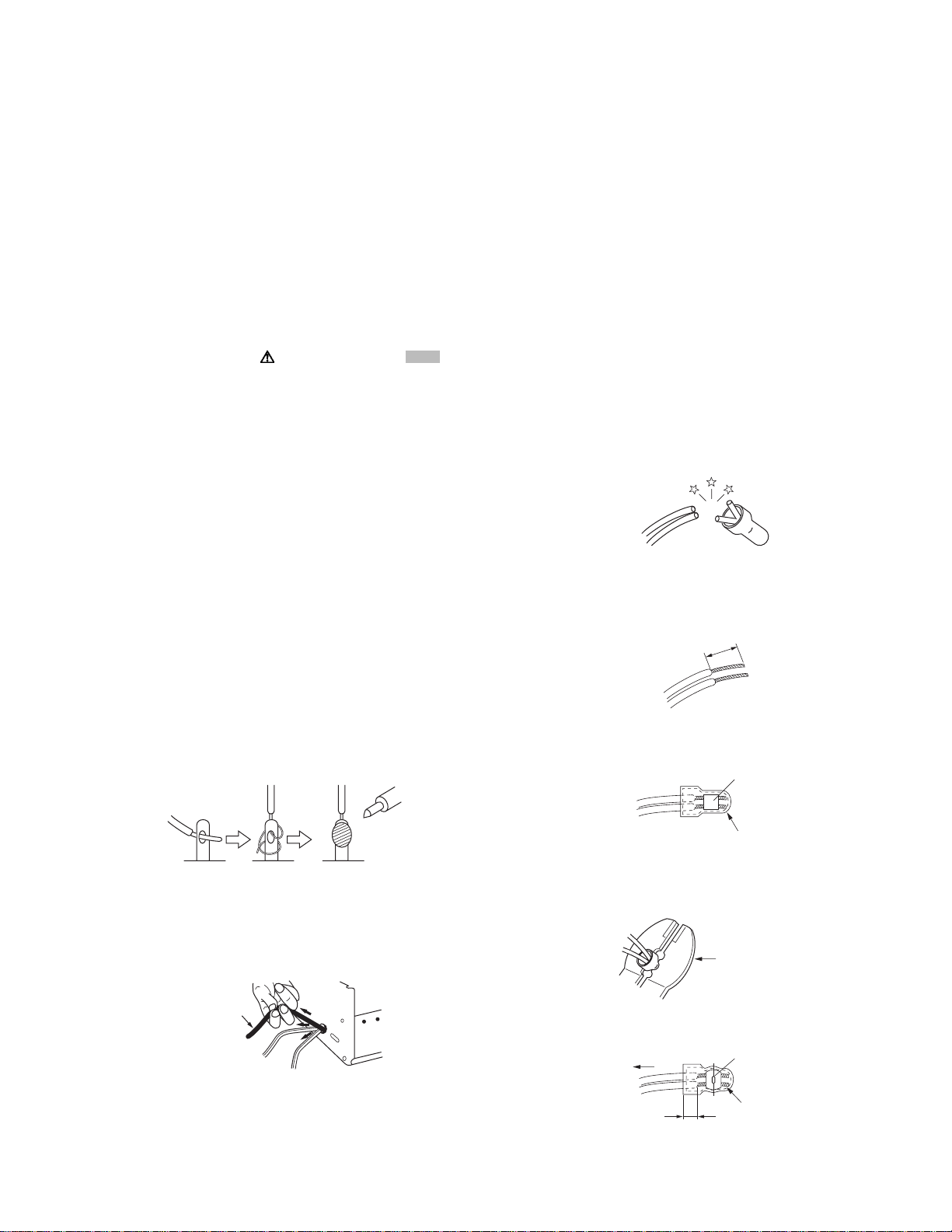
(12) Crimp type wire connectorIn such cases as when replacing
the power transformer in sets where the connections between the power cord and power trans former primary lead
wires are performed using crimp type connectors, if replacing the connectors is unavoidable, in order to prevent safety hazards, perform carefully and precisely according to the
following steps.
• Connector part number :E03830-001
• Required tool : Connector crimping tool of the proper
type which will not damage insulated parts.
• Replacement procedure
a) Remove the old connector by cutting the wires at a
point close to the connector.Important : Do not reuse a connector (discard it).
cut close to connector
Fig.1-1-3
b) Strip about 15 mm of the insulati on from the ends
of the wires. If the wires are stranded, twist the
strands to avoid frayed conductors.
15 mm
Fig.1-1-4
c) Align the lengths of the wires to be connected. In-
sert the wires fully into the connector.
Metal sleeve
Fig.1-1-1
(7) Observe that wires do not contact heat producing parts
(heatsinks, oxide metal film resistors, fusible resistors, etc.)
(8) Check that replaced wires do not contact sharp edged or
pointed parts.
(9) When a power cord has been replaced, check that 10-15
kg of force in any direction will not loosen it.
Power cord
Fig.1-1-2
(10) Also check areas surrounding repaired locations.
(11) Products using cathode ray tubes (CRTs)In regard to such
products, the cathode ray tubes themselves, the high voltage circuits, and related circuits are specified for compliance with recognized codes pertaining to X-ray emission.
Connector
Fig.1-1-5
d) As shown in Fig.1-1-6, use the crimping tool to crimp
the metal sleeve at the center position. Be sure to
crimp fully to the complete closure of the tool.
1.2
5
2
.0
5.5
Crimping tool
Fig.1-1-6
e) Check the four points noted in Fig.1-1-7.
Not easily pulled free
Wire insulation recessed
more than 4 mm
Crimped at approx. cente
of metal sleev
Conductors extended
Fig.1-1-7
(No.YD008)1-3
Page 4
1.1.2 Safety Check after Servicing
Examine the area surrounding the repaired location for d amage
or deterioration. Observe that screws, parts and wires have been
returned to original positions, Afterwards, perform the following
tests and confirm the specified values in order to verify compliance with safety standards.
(1) Insulation resistance test
Confirm the specified insulation resistance or greater between power cord plug prongs and externally exposed
parts of the set (RF terminals, antenna terminals, video and
audio input and output terminals, microphone jacks, earphone jacks, etc.).See table 1 below.
(2) Dielectric strength test
Confirm specified dielectric strength or greater between
power cord plug prongs and exposed accessible parts of
the set (RF terminals, antenna terminals, video and audio
input and output terminals, microphone jacks, earphone
jacks, etc.). See Fig.1-1-11 below.
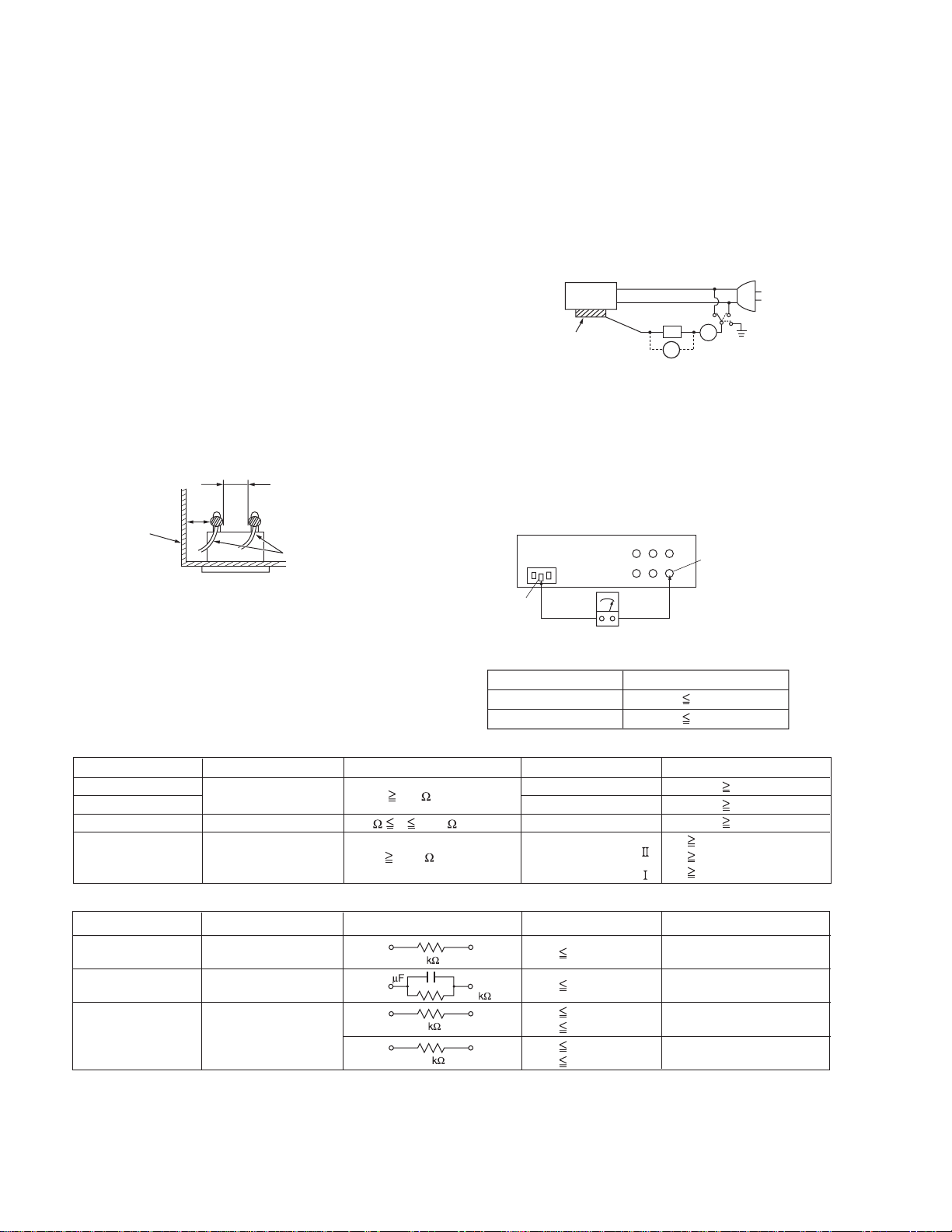
(3) Clearance distance
When replacing primary circuit components, confirm specified clearance distance (d), (d') between soldered terminals, and between terminals and surrounding metallic
parts. See Fig.1-1-11 below.
d
Chassis
d'
Power cord
primary wire
Fig.1-1-8
(4) Leakage current test
Confirm specified or lower leakage current between earth
ground/power cord plug prongs and externally exposed accessible parts (RF terminals, antenna terminals, video and
audio input and output terminals, microphone jacks, earphone jacks, etc.).
Measuring Method : (Power ON)Insert load Z between
earth ground/power cord plug prongs and externally exposed accessible parts. Use an AC voltmeter to measure
across both terminals of load Z. See Fig.1-1-9 and following Fig.1-1-12.
ab
Externally
exposed
accessible part
Z
V
c
A
Fig.1-1-9
(5) Grounding (Class 1 model only)
Confirm specified or lower grounding impedance between
earth pin in AC inlet and externally exposed accessible
parts (Video in, Video out, Audio in, Audio out or Fixing
screw etc.).Measuring Method:
Connect milli ohm meter between earth pin in AC inlet and
exposed accessible parts. See Fig.1-1-10 and grounding
specifications.
AC inlet
Earth pin
Exposed accessible part
MIlli ohm meter
Grounding Specifications
Region
USA & Canada
Europe & Australia
Grounding Impedance (Z
Z 0.1 ohm
Z 0.5 ohm
)
Fig.1-1-10
AC Line Voltage
100 V
100 to 240 V
110 to 130 V
110 to 130 V
200 to 240 V
Region
Japan
USA & Canada
Europe & Australia
Insulation Resistance (R
R 1 M /500 V DC
1 M R 12 M /500 V DC
R 10 M /500 V DC
)
Dielectric Strength
AC 1 kV 1 minute
AC 1.5 kV 1 minute
AC 1 kV 1 minute
AC 3 kV 1 minute
AC 1.5 kV 1 minute
(
Class
(
Class
Clearance Distance (d), (d'
d, d' 3 mm
d, d' 4 mm
d, d' 3.2 mm
d 4 mm
)
d' 8 mm (Power cord
d' 6 mm (Primary wire
)
Fig.1-1-11
AC Line Voltage
100 V
110 to 130 V
110 to 130 V
220 to 240 V
Region
Japan
USA & Canada
Europe & Australia
Load Z
1
0.15
1.5
2
50
Leakage Current (i)
i 1 mA rms
i 0.5 mA rms
i 0.7 mA peak
i 2 mA dc
i 0.7 mA peak
i 2 mA dc
a, b, c
Exposed accessible parts
Exposed accessible parts
Antenna earth terminals
Other terminals
Fig.1-1-12
NOTE :
These tables are unofficial and for reference only. Be sure to confirm the precise values for your particular country and locality.
)
)
)
1-4 (No.YD008)
Page 5
1.2 Preventing static electricity
Electrostatic discharge (ESD), which occurs when static electricity stored in the body, fabric, etc. is discharged, can destroy the laser
diode in the traverse unit (optical pickup). Take care to prevent this when performing repairs.
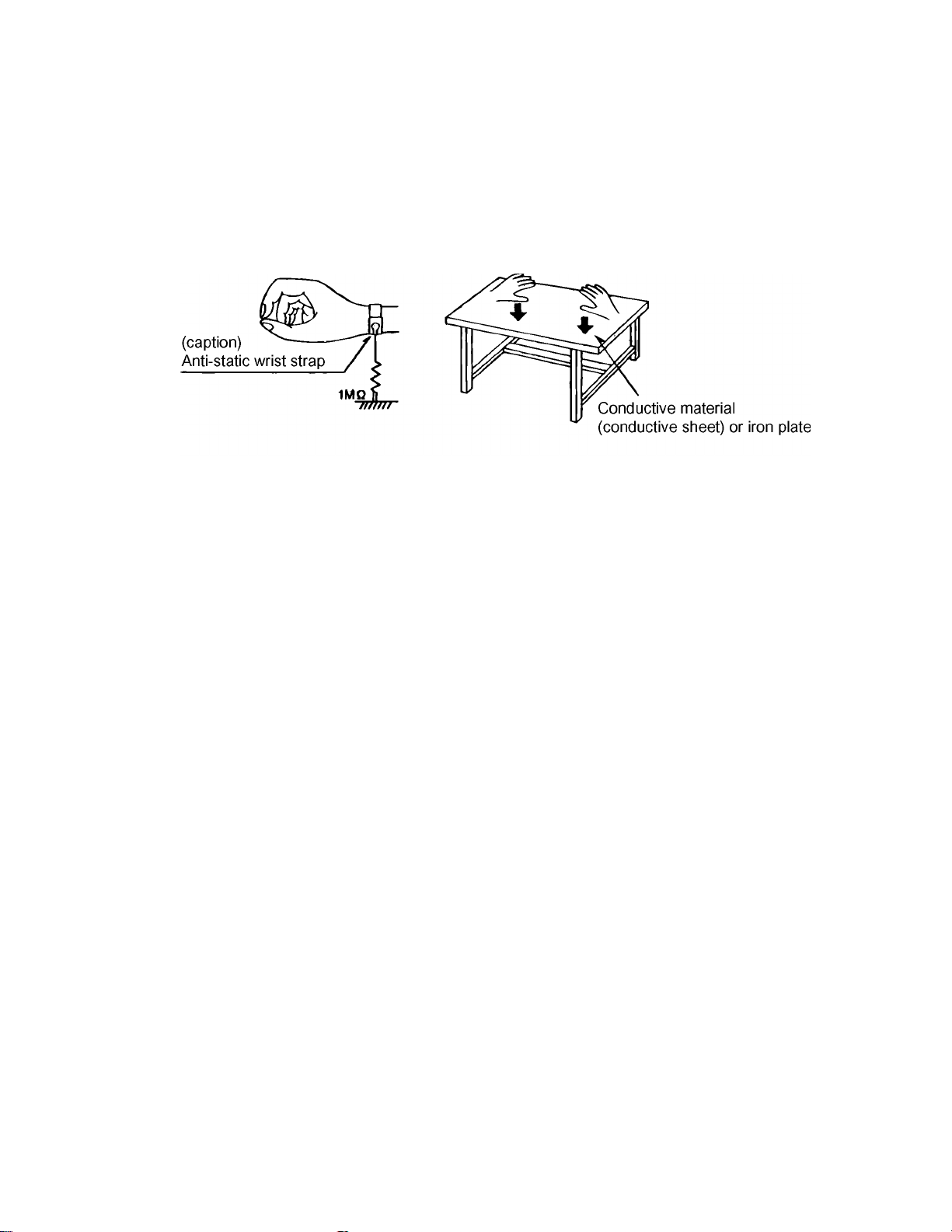
1.2.1 Grounding to prevent damage by static electricity
Static electricity in the work area can destroy the optical pickup (laser diode) in devices such as DVD players.
Be careful to use proper grounding in the area where repairs are being performed.
(1) Ground the workbench
Ground the workbench by laying conductive material (such as a conducti ve sheet) or an iron plate over it before placing the
traverse unit (optical pickup) on it.
(2) Ground yourself
Use an anti-static wrist strap to release any static electricity built up in your body.
(3) Handling the optical pickup
• In order to maintain quality during transport and before installatio n, both sides of the laser diod e on the replacement opti cal
pickup are shorted. After replacement, return the shorted parts to their original condition.
(Refer to the text.)
• Do not use a tester to check the condition of the laser diode in the optical pickup. The tester's internal power source can easily
destroy the laser diode.
(No.YD008)1-5
Page 6
1.3 Precautions for Service
1.3.1 Handling of Traverse Unit and Laser Pickup
(1) Do not touch any peripheral element of the pickup or the actuator.
(2) The traverse unit and the pickup are precision devices an d therefore must not be subjected to strong shock.
(3) Do not use a tester to examine the laser diode. (The diode can easily be destroyed by the internal power supply of the tester.)
(4) To replace the traverse unit, pull out the metal short pin for protection from charging.
(5) When replacing the pickup, after mounting a new pickup, remove the solder on the short land which is provided at the center of
the flexible wire to open the circuit.
(6) Half-fixed resistors for laser power adjustment are adjusted in pairs at shipment to match the characteristics of the optical block.
Do not change the setting of these half-fixed resistors for laser power adjustment.
1.3.2 Destruction of Traverse Unit and Laser Pickup by Static Electricity
Laser diodes are easily destroyed by static electricity charged on clothingor the human body. Before repairing peripheral elements of
the traverse unit or pickup, be sure to take the following electrostatic protection:
(1) Wear an antistatic wrist wrap.
(2) With a conductive sheet or a steel plate on the workbench on which the traverse unit or the pick up is to be repaired, ground the
sheet or the plate.
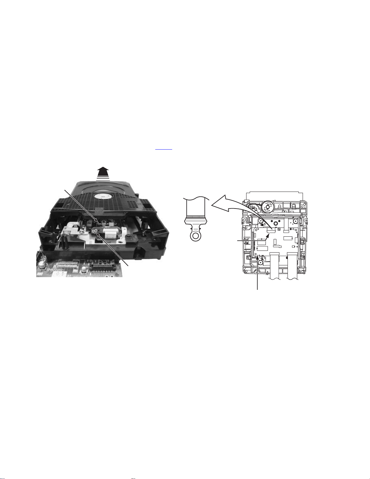
(3) It solders to two short circuit sections on the substrate of a pick-up.
(4) After removing the flexible wire from the connector (CN101
(5) Short-circuit the laser diode by soldering the land which is provided at the center of the flexible wire for the pickup.
After completing the repair, remove the solder to open the circuit.
), short-circuit the flexible wire by the metal clip.
Pick-up
Short circuit
* Please refer to the SECTION3 DISASSEMBLY method for details.
CN101
DVD SERVO CONTROL BOARD
1-6 (No.YD008)
Page 7
SECTION 2
SPECIFIC SERVICE INSTRUCTIONS
2.1 Different table of feature
The following table indicates ma in different p oints between models HR-XVC22UC, HR-XVC23UC, HR-XVC26US, HR-XVC27UC and
HR-XVC27US.
HR-XVC22UC HR-XVC23UC HR-XVC26US HR-XVC27UC HR-XVC27US
BODY COLOR BLACK PURE SILVER BLACK PURE SILVER ←
REMOCON COLOR BLACK GRAY BLACK GRAY ←
A/V CABLE SUPPLIED ← OPTIONAL ←←
RF CONVERTER NOT USED ← USED ←←
NOTE :
Mark ← is same as left.
2.2 Service position
This unit has been designed so that the Mechanism an d Main
board assemblies can be removed together from the bottom
chassis. Before diagnosing or servicing the circuit boards, take
out the major parts from the bottom chassis.
2.2.1 How to set the "Service position"
(1) Refer to the disassembly procedure and perform the disas-
sembly of the major parts before removing the Mechanism
assembly.
(2) Remove the screws that fix the Mechanism, Main board as-
sembly to the bottom chassis. If any other screws are used
to fix the boards, remove them also.
(3) Remove the combined Mechanism and Main board assem-
blies.
(4) If any other major parts are used, remove them also.
(5) Connect the wires an d connectors of the major parts that
have been removed in steps (1) to (4). (Refer to Fig. 2-2a.)
(6) Place the combined Mechanism, Main board and other
board assemblies upside down.
(7) Insert the power cord plug into the power outlet and then
proceed with the diagnostics and servicing of the board as-
sembly.
Notes:
• Before inserting the power cord plug into the power out-
let, make sure that none of the electrical parts are able
to short-circuit between the workbench and the board
assembly.
• For the disassembly procedure of the major parts an d
details of the precautions to be taken, see "Removing
the major parts".
• If there are wire connections from the Main board and
Mechanism assemblies to the other major parts, be sure
to remove them (including wires connected to the major
parts) first before performing step (2).
• When carrying out diagnosis and repair of the Main
board assembly in the "Service position", be sure to
ground both the Main board and Mechanism assemblies. If they are improperly grounded, there may be
noise on the playback picture or FDP counter display
may move even when the mechanism is kept in an inoperative status.
• In order to diagnose the playback or recording of the
cassette tape, set the Mechanism assembly to the required mode before placing it upside do wn. If the mechanism mode is changed (including ejection) while it is in
an upside down position the tape inside may be damaged.
• For some models, the mechanism and board assem-
blies are attached by connectors only. When carrying
out a diagnosis or repair of the boards in the "Service
position", make sure that the connectors are not disconnected.
TP111 D.FF
TP4001 CTL.P
TP106 PB FM
TP2253 A.PB FM
Display board assembly
Main board assembly
Jack board assembly
Fig.2-2a
2.3 Jig RCU mode
This unit uses the following two modes for receiving remote control codes.
(1) User RCU mode:Ordinary mode for use by the user.
(2) Jig RCU mode: Mode for use in production and servicing.
When using the Jig RCU, it is required to set th e VCR to the Jig
RCU mode (the mode in which codes from the Jig RCU can be
received). As both of the above two modes are stored in the EEPROM, it is required to set the VCR back to the User RCU mode
each time that an adjustment is made or to check that the necessary operations have been completed.These modes can be set
by the operations described below.
Note:
• Confirm the RCU mode when exchanged parts. Since
some SERVICE PARTS sets the VCR to the Jig RCU
(No.YD008)1-7
Page 8
mode as initial setting. Therefore please set the VCR to
the user RCU mode after replacing the EEPROM.
User RCU mode
Jig RCU mode
(2) To clean the parts of the tap e transport system other than
the upper drum, use a piece of closely woven cloth or a cotton swab soaked with alcohol.
(3) After cleaning, make sure that the cleaned parts are com-
pletely dry before using the cassette tape.
( not displayed)
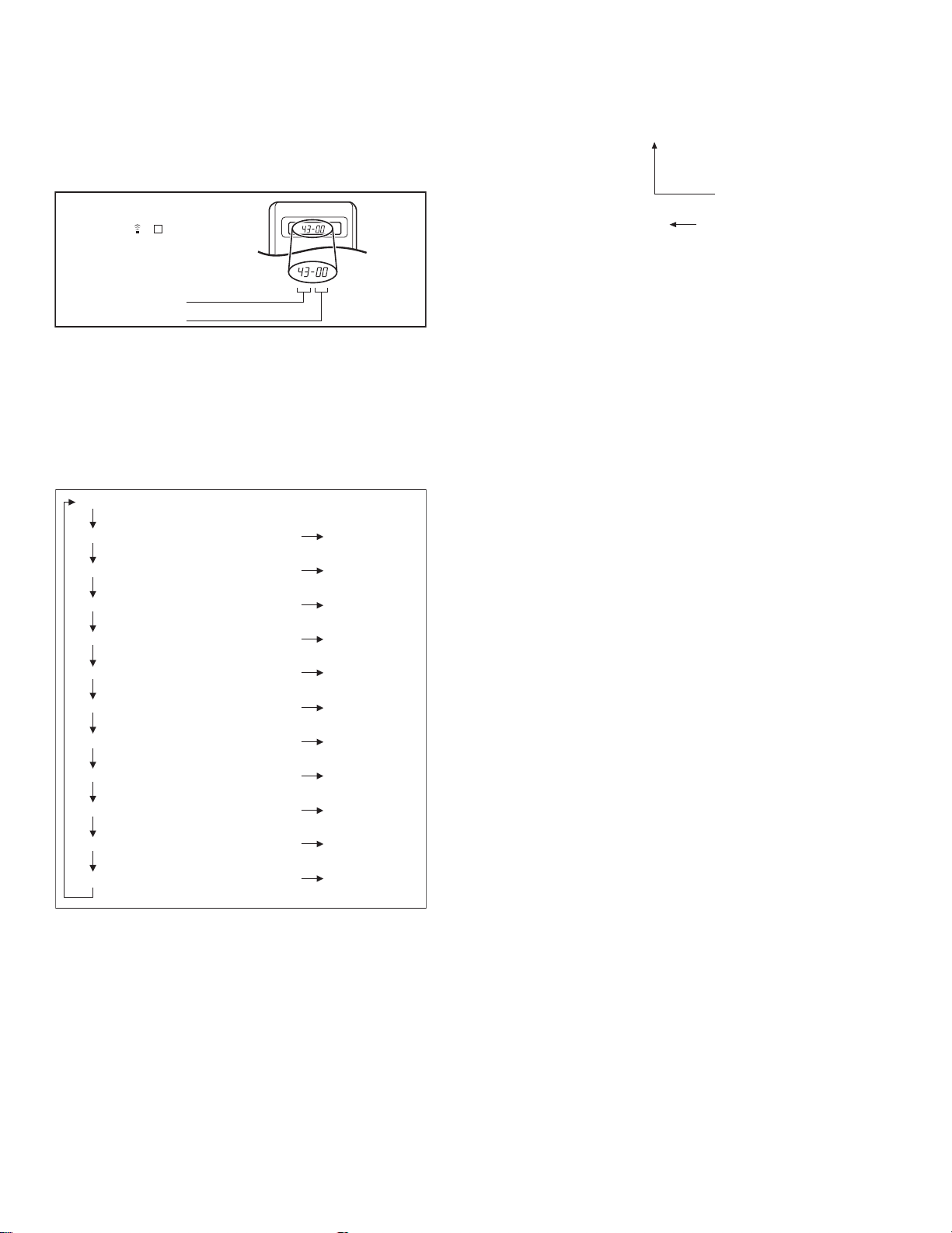
Fig.2-3a User/Jig RCU mode
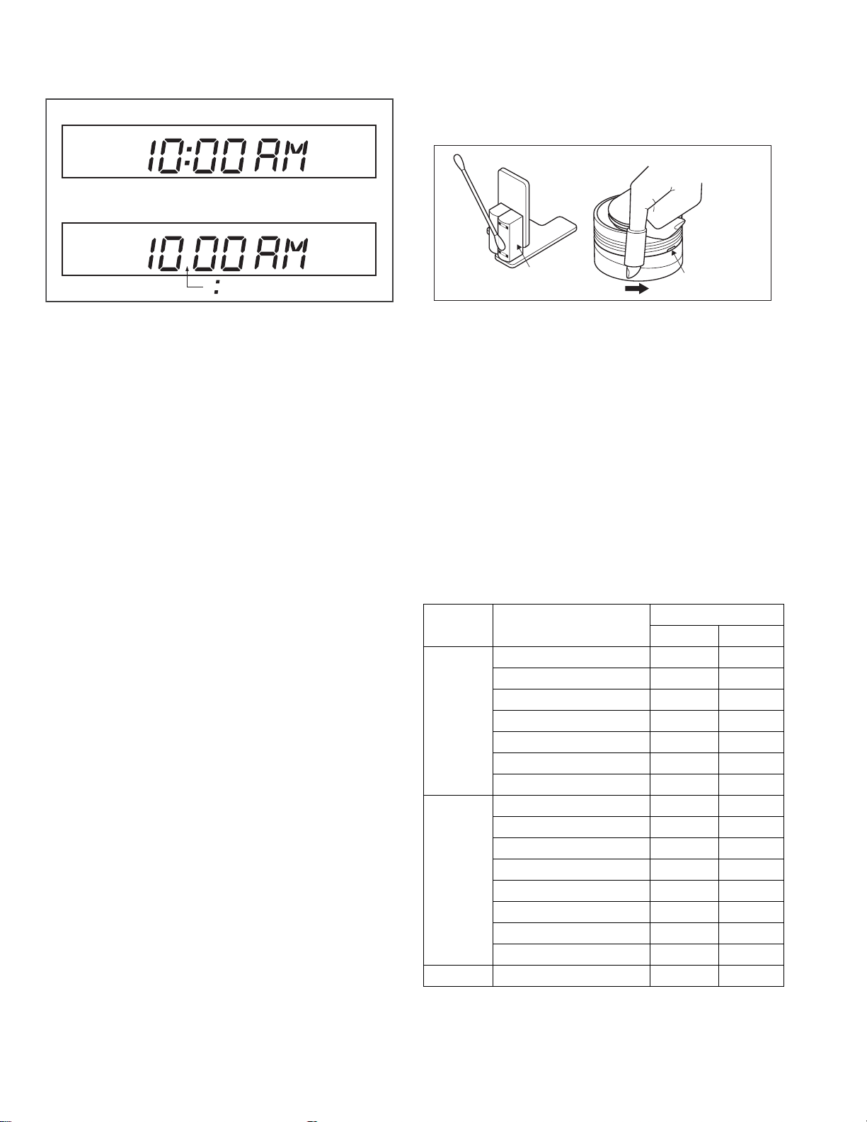
2.3.1 Setting the Jig RCU mode
(1) Turn on the power.
(2) Press the following remocon keys continuously within 2
seconds " SET UP " → " 2 " → " 8 " → " ENTER ".
When the VCR is set to the Jig RCU mode, the symbols
( " : " ) in the time display of the FDP are turned off.
(Refer to Fig.2-3a)
2.3.2 Setting the User RCU mode
(1) Turn off the power.
(2) Press the "REC" and "PAUSE" buttons of the VCR si mul-
taneously. Alternatively, transmit the code "80" from the Jig
RCU.
2.4 Mechanism service mode
This model has a unique function to enter the mechanism into every operation mode without loading of any cassette tape. This
function is called the "Mechanism service mode".
2.4.1 How to set the "Mechanism service mode"
(1) Set the VCR to the Jig RCU mode (the mode in which
codes from the Jig RCU can be received)
(2) Transmit the code "E5" from the Jig RCU.
(3) Release the lug of th e Cassette holder and then slid e the
Cassette holder toward the direction where the Cassette
holder is loaded by manually.
(4) The cassette holder lowers and, when the loading has
completed, the mechanism enters the desired mode.
When the VCR is set to the Mechanism service mode, the
symbols ("Timer") in the FDP (LED) are blinked.
2.4.2 How to exit from the "Mechanism service mode"
(1) Unplug the power cord plug from the power outlet.
2.5 Maintenance and inspection
2.5.1 Cleaning
Regular cleaning of the transport system parts is desirable but
practically impossible. So make it a rule to carry out cleaning of
the tape transport system whenever the machine is serviced.
When the video head, tape guide and/or brush get soiled, the
playback picture may appear inferior or at worst disappear, resulting in possible tape damage.
Note:
• Absolutely avoid sweeping the upper drum vertically as
this will cause damage to the video head.
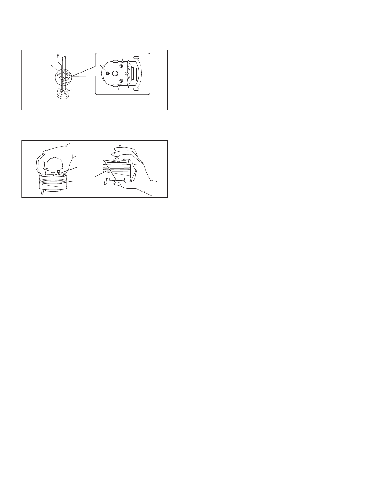
(1) When cleaning the upper drum (especially the video head),
soak a piece of closely woven cloth with alcohol and while
holding the cloth onto the upper drum by the fingers, turn
the upper drum counterclockwise.
A/C head
Fig.2-5a
2.5.2 Lubrication
With no need for periodical lubrication, you have only to lubricate
new parts after replacement. If any oil or grease on contact parts
is soiled, wipe it off and newly lubricate the parts.
Note:
• See the "mechanism assembly" diagram of the "parts
list" for the lubricating or greasing spots, and for the
types of oil or grease to be used.
2.5.3 Suggested servicing schedule for main components
The following table indicates the suggested perio d for such service measures as cleaning, lubrication and replacement. In practice, the indicated periods will vary widely according to
environmental and usage conditions. However, the indicated
components should be inspected when a set is b rought for service and the maintenance work performed if necessary. Also
note that rubber parts may deform in time, even if the set is not
used.
System Parts name
Drum assembly C,X X
A/C head C,X C,X
Tape
transport
Drive
Other Rotary encoder X
C : Cleaning
X : Inspection or Replacement if necessary
Pinch roller arm assembly C C
Full erase head C C
Tension arm assembly C C
Capstan motor (Shaft) C C
Guide arm assembly C C
Capstan motor X
Capstan brake assembly X
Main brake assembly X
Belt (Capstan) X X
Loading motor X
Clutch unit X
Worm gear X
Control plate X
Video heads
Operation hours
1000H 2000H
1-8 (No.YD008)
Page 9
SECTION 3
DISASSEMBLY
3.1 Removing the major parts
3.1.1 Destination of connectors
Two kinds of double-arrows in connection tables respectively
show kinds of connector/wires.
: The connector of the side to remove
CONN. No. PIN No.CONNECTOR
WR2a
WR2b
Main CN101
Main CN103
Destination of connectors
CONN. No. PIN No.CONNECTOR
WR2a
WR2b
WR3a
WR3b
WR4a
WR4b
WR4c
Main
Main
Main
Drum
assembly
Main
Main
Main
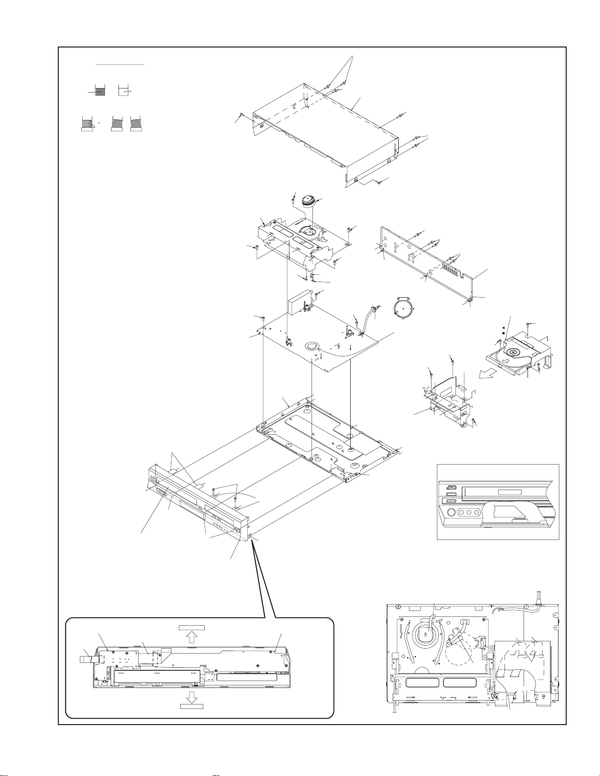
3.1.2 How to read the procedure table
This table shows the steps for disassembly of the externally furnished parts and board assemblies. Reverse these steps when
re-assembling them.
Step/
Loc No.
[1] Top cover 3-1a
(1) (2) (3) (4) (5)
Part Name
Bracket 2(S1c)
(1) Order of steps in Procedure
When reassembling, perform the step(s) in the reverse order.
These numbers are also used as the identification (loca-
tion) No. of parts Figures.
(2) Part name to be removed or installed.
(3) Fig. No. showing procedure or part location.
(4) Identification of part to be removed, unhooked, un locked,
released, unplugged, unclamped or unsoldered.
P= Spring, W= Washer, S= Screw, L= Locking tab, SD=
Solder, CN**(WR**)= Remove the wire (WR**) from the
connector (CN**).
Note:
• The bracketed ( ) WR of the connector symbol are
assigned nos. in priority order and do not correspond to those on the spare parts list.
(5) Adjustment information for installation
: Wire: Flat wire : Board to board (B-B)
Digital CN761
Digital CN762
CN7103
CN3102
CN2001
CN7302
CN7301
CN8301
Jack
Display
A/C head
Main
DVD
servo control
DVD
servo control
DVD
servo control
Fig.
No.
4(S1a),(S1b),3(L1a), <Note 1a>
2(SD1a),(P1a),(W1a),
CN1(WR1a),
----------------------------------------
CN7191
CN7003
CN503
CN501
Point Note
CN1
CN1
40
10
10
22
6
9
17
19
5
3.1.3 Disassembly procedure
Step/
Loc No.
[1]
[2]
[3]
[4]
[5]
[6]
Part Name
Top cover
Front panel assembly
(Display board assembly)
(Jack board assembly)
Mechanism assembly
(Drum assembly)
DVD unit
(Bracket)
Rear cover
Main board assembly
Fig.
No.
3-1d
3-1a
3-1d
3-1b
3-1c
3-1d
3-1d
3-1d
3-1d
Point Note
8(S1a)
4(L2a),5(L2b),2(S2a)
CN7103(WR2a),
CN3102(WR2b)
CN2001(WR3a)
3(S3a),(S3b)
--------------------------
CN(WR3b)
(S3c),(S3d),(S3e)
3(S4a),3(S4b),
CN7302(WR4a),
CN7301(WR46),
CN8301(WR4c)
5(S5a),5(L5a)
3(S6a)
<Note 2a>
<Note 2b>
<Note 2a>
<Note 3a>
<Note 3b>
<Note 3c>
<Note 2a>
• Be careful not to damage the connector and wire etc. during
connection and disconnection.
• When connecting the flat wire to the connector, be careful with
the flat wire direction.
<Note 2b>
• When reattaching the Front panel assembly, make sure that
the door opener of the Side frame (R) is lowered in position prior to the reinstallation.
• When reattaching the Front panel assembly, pay careful attention
to the switch lever of the Front panel assembly not to make it
touch the switch knob of the Main board assembly from the side.
• When reattaching the Front panel assembly, lift the Casse tte
door slightly.
Door
opener
Side
frame(R)
Switch
knob
Switch
lever
Fig.3-1a
<Note 3a>
• When reattaching the Mechanism assembly, secure the
screws (S3a to S3b) in the order of 1,2,3.
<Note 3b>
• When reattaching the Mechanism assembly, be sure to ali gn
the phase of the Rotary encoder on the Main board assembly.
• When reattaching the Mechanism assembly, set the “Mechanism assembling mode”. [See “MECHANISM ASSEMBLY
SERVICE MANUAL (No. 86700)”.]
• When reattaching the Mechanism assembly to the Main board
assembly, take care not to damage the sensors and switch on
the Main board assembly.
(No.YD008)1-9
Page 10
<Note 3c>
• When reattaching the Drum assembly, secure the screws (S3c
to S3e) in the order of c, d, e.
Mechanism
assembly
(S3d)
(S3c)
(S3e)
(S3d)
(S3e)
Drum
assembly
<Note 3c>
<NOTE>
Attach the Drum assembly appropriately,
since the installation state of the Drum assembly
influences the FM WAVEFORM LINEARITY
greatly.
(S3c)
HOOK
Fig.3-1b
• When handling the drum assembly alone, hold it by the motor
or shaft. Be careful not to touch other parts, especially the video heads. Also take care not to damage the connectors.
Shaft
Motor
Video heads
Fig.3-1c
1-10 (No.YD008)
Page 11
1.Insert direction of FFC WIRE as follows.
electrode side
NOTE
right side back side
supporting side
2.FFC WIRE and DRUM FPC WIRE should be insert as follows.
OK
CN CN CN
3.Insert the wire to even the root of connector completely
at the same time as inserting each wire.
4.Check to see that outside parts.TOP COVER,BOTTOM COVER,
FRONT PANEL, etc are fixed certainly to the BOTTOM CHASSIS
with SCRWES.
NG
90
5.Pay attention NOT to make any scratches on FRONT PANEL.
6.Pay close attention not to cut any Sheath of WIRE by sharp edge
of CHASSIS while Wireing Process.
[6]Main board assembly
(L2a)
j
(L2b)
(L2b)
Cassette door
<Note 2b>
(L2b)
(S1a)
(S1a)
[1]Top cover
(S1a)
(S1a)
(S1a)
(S1a)
(S3a)
1
[3]Mechanism
assembly
(S3a)
j
3
j
(S3c)
(S6a)
60
U
T
Bottom chassis
(S2a)
j
j
(L2a)
j
01
[3]Drum assembly
f
e
(S3e)
(S6a)
JS3001
c
i
i
(S3d)
a
(S3a)
2
(L5a)
i
(S3b)
i
(L5a)
JS3001
(S6a)
m
c
b
i
a
DVD bracket
boardassembly
(S5a)
(S5a)
(S5a)
[5]Rear cover
i
(L5a)
(L5a)
i
i
(L5a)
<Phase alignment>
.
Accord the position of V gap on R.ENCORDER and PWB silk
.
Accord the position of Boss on R.ENCORDER and PWB silk
(S4b)
[4]Bracket
(S4b)
f
j
e
c
d
d
c
j
[4]DVD unit
L
P
*
***
(S4a)
b
d
*
d
(S4b)
i
i
NOTE) FFC WIRE SHOULD BE POSITIONED BELLOW CASSETTE DOOR.
(FOR AVOID FFC WIRE DISTURB CASSETTE IN AND OUT.)
CN3102
(S4a)
d
(S4a)
(L2b)
Jack board assembly
(WR2a)
<Note 2a>
1
CN7191
[2]Front panel
assembly
CN7003
5
BOTTOM SIDE
4
TOP SIDE
(WR2b)
<Note 2a>
3
4
2
Display board assembly
3
1
2
Insert the bushing of POWER CORD so as not to twist the cord.
(WR3b)
<Note 2b>
CN2001
(WR4b)
(WR4a)
<Note 2b>
<Note 2b>
A/C HEAD
CN503 CN501
CN7103
from FRONT PANEL
(JACK CN7191)
CN3102
(WR3a)
<Note 2b>
CN7302
CN1
CN7301
Make a crease.
CN8301
right side
(WR4c)
<Note 2b>
back side
Fig.3-1d
(No.YD008)1-11
Page 12
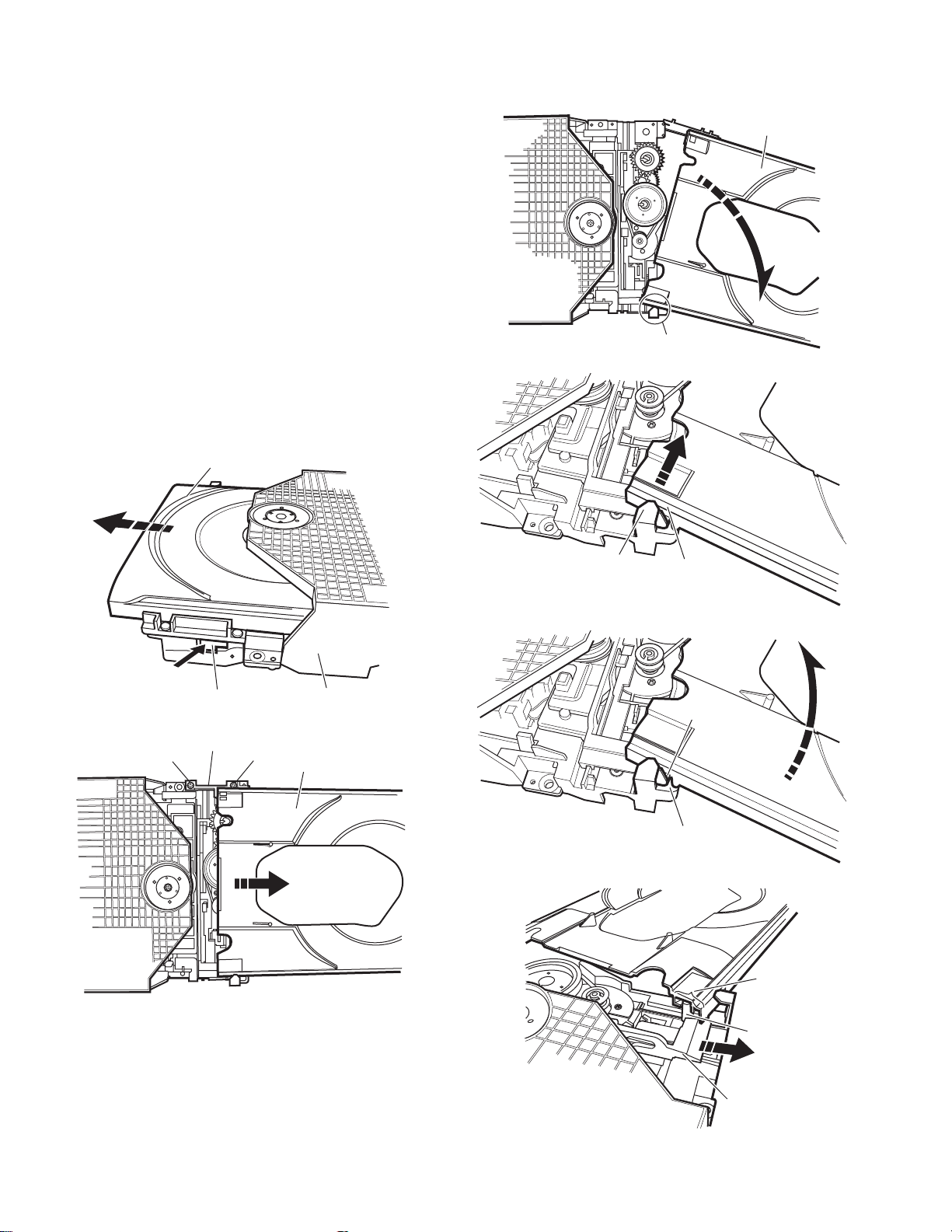
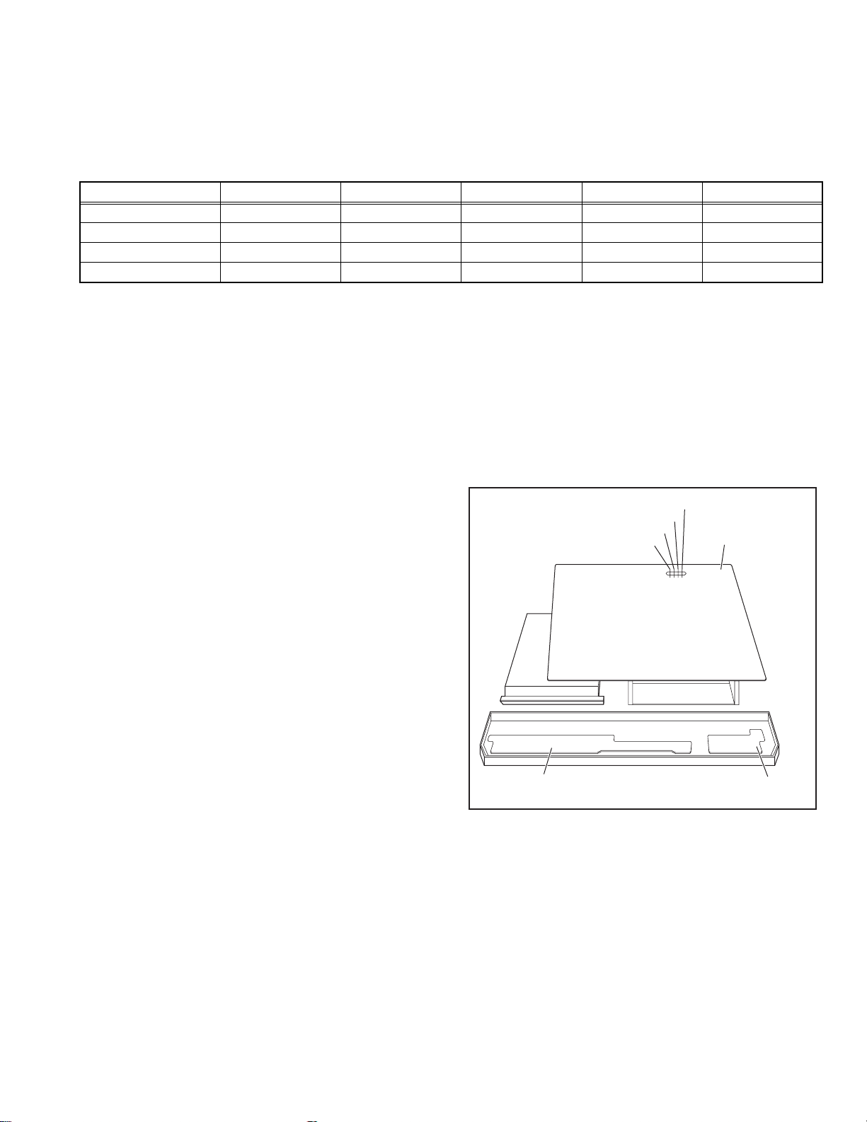
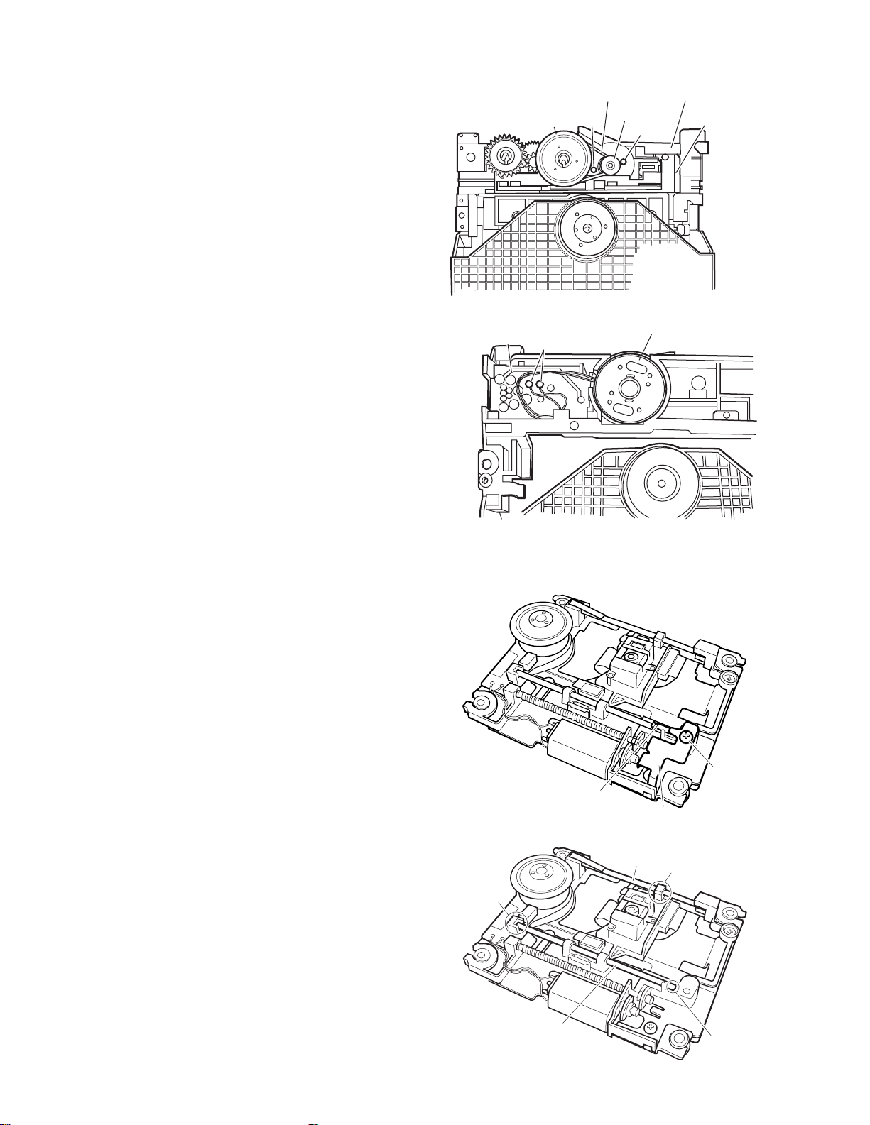
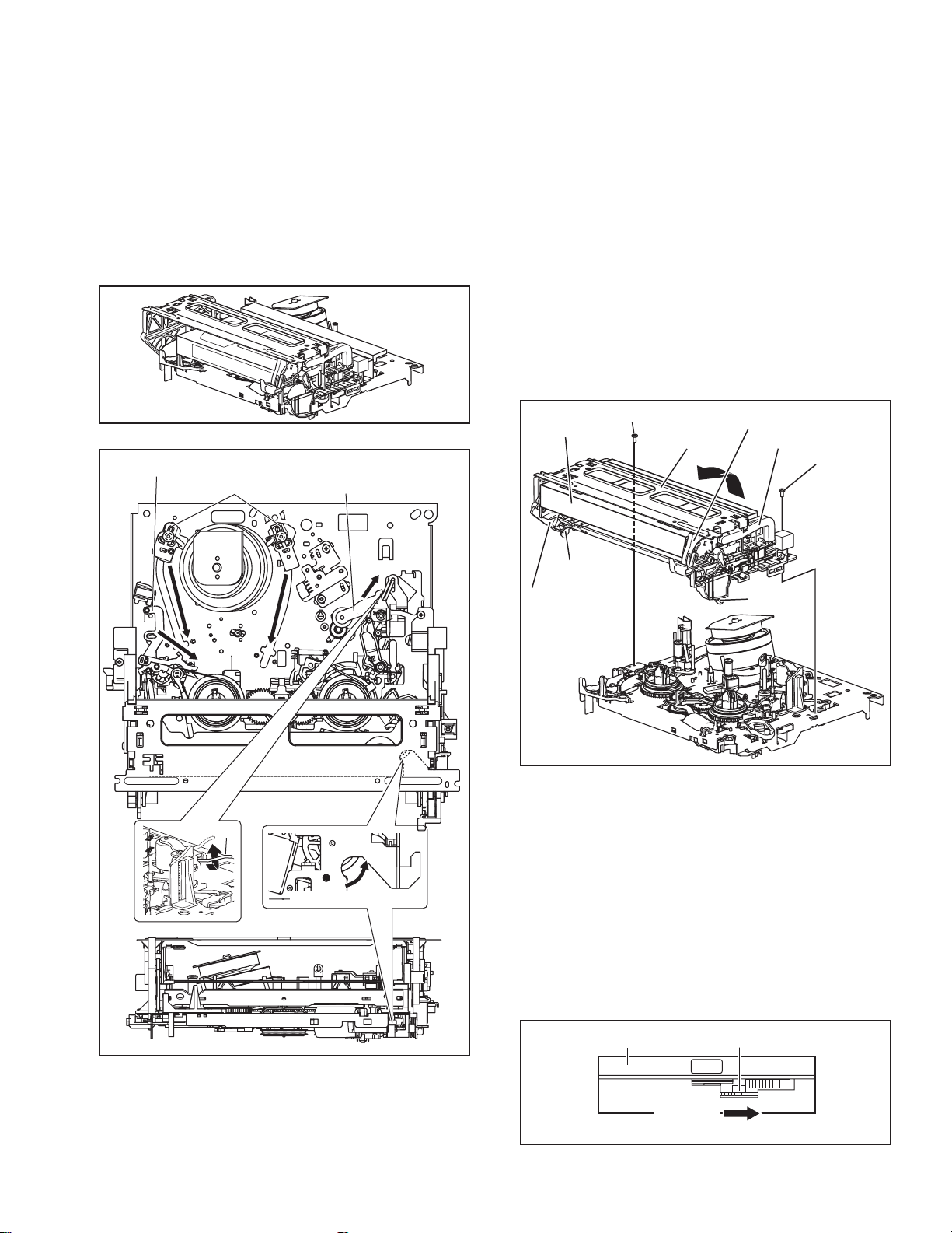
3.2 Loading mechanism assembly
Projection of the tray
3.2.1 Removing the tray (See Figure 3-2a, Figure 3-2b, Figure 3-2c, Figure 3-2d, Figure 3-2e, Figure 3-2f)
(1) Push a of the slide ca m on the ho le in the right side of the
loading base by using a driver until it stops. (See Figure 32a.)
(2) The tray comes out. Pull the tray in a front direction until it
stops.
(3) Remove the two screws A attaching the slide bracket. (See
Figure 3-2b.)
(4) Tilt the tray in a directi on of the arrow around the point in
the left rear part of the tray. (See Figure 3-2c.)
(5) The rail of the tray is removed from b of the loading base.
Then, remove the tray upward. (See Figure 3-2d.)
Attaching the tray:
Engage c of the loading base to the projection of the tray while
tilting the tray to the left. Turn the tray in a direction of the arrow, and attach the slide bracket. (See Figure 3-2e.)
Note:
Prior to the procedure above, move the slide cam in a direction
of the arrow so that d of the slide cam can be inserted in e of
the tray. (See Figure 3-2f.)
Tray
The point in the left rear part
Fig.3-2c
Tray
Push
Slide cam part a
Slide bracket
A
Fig.3-2a
Fig.3-2b
A
Loading base
Tray
Loading base part b
Rail of the tray
Fig.3-2d
Projection of the tray
Loading base part c
Fig.3-2e
Part e
1-12 (No.YD008)
Part d
Slide cam
Fig.3-2f
Page 13
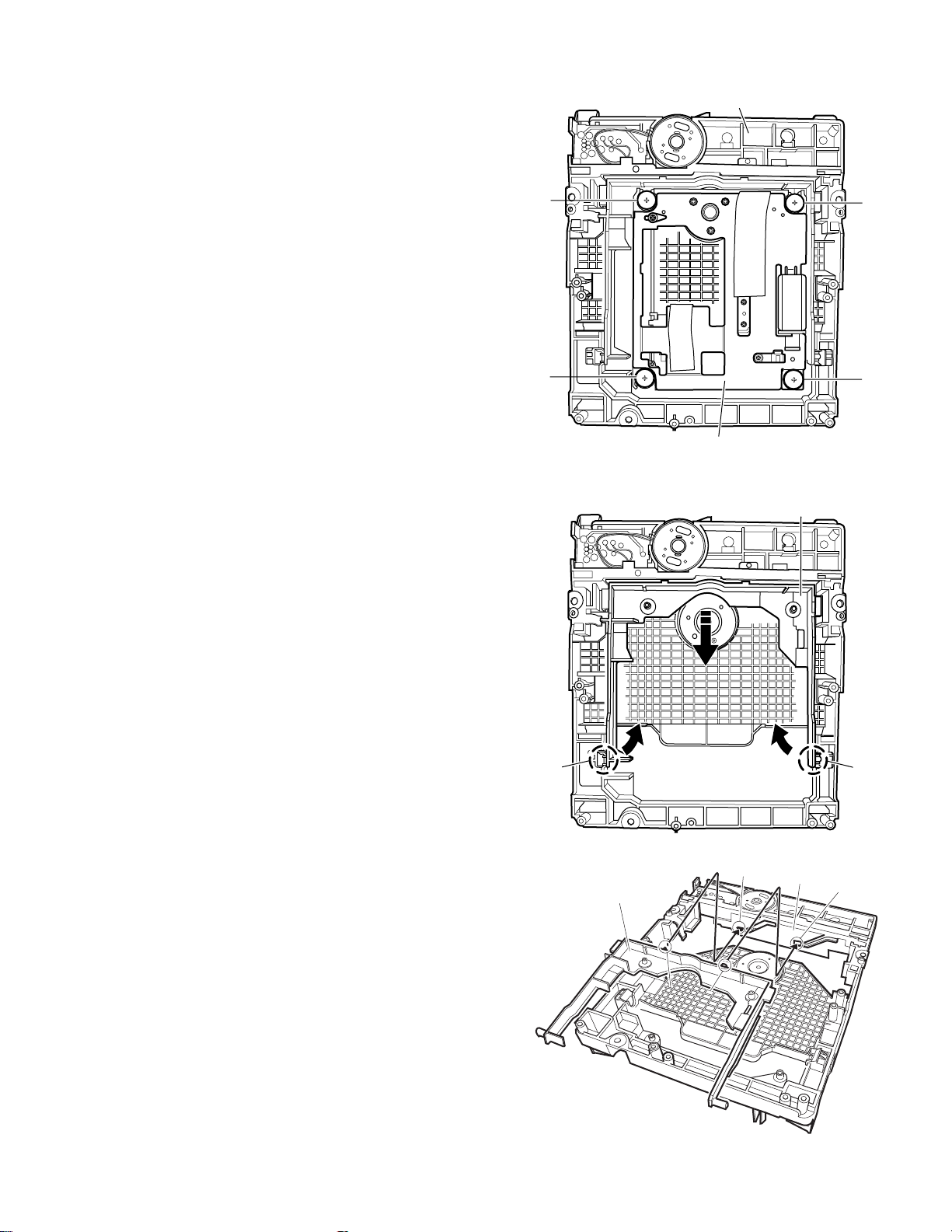
3.2.2 Removing the traverse mechanism assembly (See Figure 3-2g)
f
Shaft
Reverse the loading mechanism assembly. Remove the four
screws B attaching the traverse mechanism assembly. Remove
the traverse mechanism assembly upward.
Loading mechanism assembly
3.2.3 Removing the elevator (See Figure 3-2h and Figure 3-2j)
• Prior to the following procedure, remove the traverse mechanism assembly.
(1) Remove the two arms of the el evator from the two parts f
by moving the arms in a direction of the arrow.
(2) Pull out the elevator in a rear direction.
Attaching the elevator:
Engage the two holes g to the two shafts on the front part of
the elevator. And then, attach the elevator.
B
B
B
B
Traverse mechanism assembly
Fig.3-2g
Elevator
Part f
Fig.3-2h
g
Slide cam
Elevator
Shaft
Fig.3-2j
(No.YD008)1-13
Part
g
Page 14
3.2.4 Removing the loading motor (See Figure 3-2k and Figure 3-2l)
• Prior to the following procedure, remove the tray, the traverse
mechanism assembly, and the elevator.
(1) Remove the belt from the pulley.
(2) Remove two screws C attaching the loading motor.
(3) Remove two solders h on the switch board.
Switch board
Pulley
Part h
Belt
Pulley
C
Fig.3-2k
Loading base
Slide cam
C
Loading motor
3.3 Traverse mechanism assembly
3.3.1 Removing the pickup (See Figure 3-3a, Figure 3-3b)
• Prior to the following procedure, remove the traverse mechanism assembly.
(1) Remove one screw D attaching the plate.
(2) Remove the plate and the leaf spring.
(3) Lift i of the shaft 1, and pull out the shaft 1 from j.
(4) Remove k of the pickup from the shaft 2.
Attaching the pickup:
(1) Engage k of the pickup to the shaft 2.
(2) Insert the shaft 1 in j, and attach the shaft 1 to i.
(3) Attach the leaf spring, and then a ttach the p late. Fix the
leaf spring and the plate by using the screw D.
Fig.3-2l
D
Leaf spring
Plate
Fig.3-3a
Shaft 2
Part k
Part j
1-14 (No.YD008)
Shaft 1
Part i
Fig.3-3b
Page 15
SECTION 4
ADJUSTMENT
4.1 Before adjustment
4.1.1 Precaution
• The adjustments of this unit include the mechanism com-
patibility and electrical adjustments. During the performance of this work, be sure to observe the precautions for
each type of adjustment.
• If there is a reference to a signal input method in the signal
column of the adjustment chart, “Ext. S-input” means the
Y/C separated video signal and “Ext. input” means the
composite video signal input.
• Unless otherwise specified, all measuring points and
adjustment parts are located on the Main board.
4.1.2 Required test equipments
• Color (colour) television or monitor
• Oscilloscope: wide-band, dual-trace, triggered delayed sweep
• Signal generator: RF / IF sweep / marker
• Signal generator: stairstep, color (colour) bar [NTSC]
• Recording tape
• Digit-key remote controller(provided)
4.1.3 Required adjustment tools
--- : Not used
z
: Used
Mechanism
compatibility
adjustment
Roller driver
z ---
Jig RCU --- z
Back tension cassette gauge z ---
Alignment tape(MHP) z ---
Alignment tape(MHP-L) zz
Roller driver
PTU94002
Alignment tape
(SP, stairstep, NTSC)
MHP
CD-DA test disc
CTS-1000
Jig RCU
PTU94023B
Alignment tape
(EP, stairstep, NTSC)
MHP-L
Back tension cassette gauge
Electrical
adjustment
PUJ48076-2
DVD test disc
VT-501
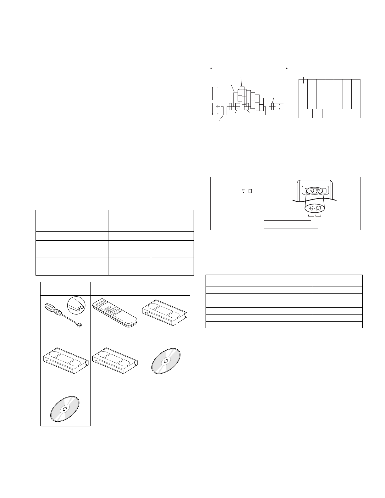
4.1.4 Color (colour) bar signal,Color (colour) bar pattern
Color(colour) bar signal [NTSC]
White(100%)
White(75%)
100 IRE
1V
40 IRE
Horizontal sync
Yellow
Cyan
Green
Magenta
Red
QI
Blue
Color(colour) bar pattern [NTSC]
(75%)
Burst
40 IRE
White
Yellow
White
Q I Black
100%
Cyan
Green
Magenta
Red
Blue
4.1.5 Switch settings
When adjusting this unit, set the VCR mode and switches
as described below.
• When using the Jig RCU, it is required to set the VCR to the
Jig RCU mode (the mode in which codes from the Jig RCU can
be received). (See "section 2 SPECIFIC SERVICE INSTRUCTIONS".)
Jig RCU
[Data transmitting method]
Depress the " "( 3 ) button
after the data code is set.
CUSTOM CODE
43: A CODE
DATA CODE
INITIAL MODE
Fig.4-1 Jig RCU [PTU94023B]
• Set the switches as shown below unless otherwise specified
on the relevant adjustment chart. The switches that are not listed below can be set as desired.
If the VCR is not equipped with the functions detailed below ,
setup is not required.
AUTO PICTURE/VIDEO CALIBRATION/
B.E.S.T./D.S.P.C.
PICTURE CONTROL/SMART PICTURE NORMAL/NATURAL
VIDEO STABILIZER OFF
TBC ON
Digital 3R ON
VIDEO NAVIGATION/TAPE MANAGER OFF
BLUE BACK OFF
OFF
4.1.6 Manual tracking mode (Auto tracking ON/OFF) set-
ting
(1) In order to set to the manual tracking mode during ta pe
playback, press the “SP/EP(LP)”button on the remote control unit.
• Each press of the button switches the auto tracking ON
or OFF.
• When the manual tracking mode is set, the tracking is
placed at the center position.
(2) Press “channel +/-” to adjust the tracking manually.
(No.YD008)1-15
Page 16
4.2 Mechanism compatibility adjustment (VHS SECTION)
Notes:
• Although compatibility adjustment is very important, it
is not necessary to perform this as part of the normal
servicing work. It will be required when you have replaced the A/C head, drum assembly or any part o f the
tape transport system.
• To prevent damaging the alignment tape in the compat-
ibility adjustment, prepare a cassette tape (for self-recording/playback), perform a test on it by transporting it
and making sure that the tape is not bent by the tape
transport mechanisms such as in the guide rollers.(See
Fig.4-2b.)
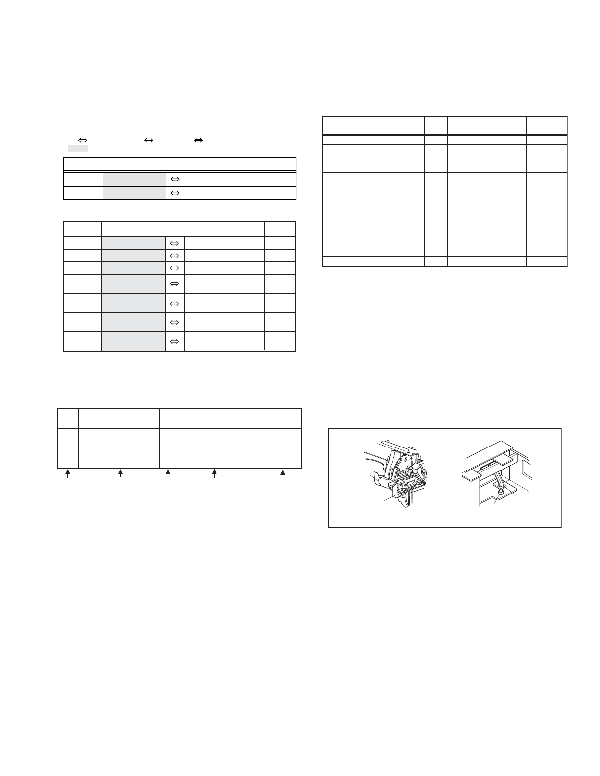
4.2.1 Tension pole position
Notes:
• This adjustment must be performed every time the ten-
sion band is replaced.
Signal (A) • Back tension cassette gauge [PUJ48076-2]
Mode (B1)
Adjustment part (F) • Adjust pin [Mechansim assembly]
Specified value (G)
•PB
(B2)
• Eject end
• 25 - 51 gf•cm (2.45 - 5 x 10
-3
Nm)
(1) Play back the back tension cassette gauge (A).
(2) Check that the indicated value on the left side gauge is
within the specified value (G).
(3) If the indicated value is not within the specified value (G),
perform the adjustment in a following procedure.(See
Fig.4-2a.)
a) Remove the top frame, cassette holder and side
frames (L/R) all together. (Refer to the SERVICE
MANUAL No.86700 [MECHANISM ASSEMBLY].)
b) Rotate the loading motor gear to move the control
plate so that the triangular stamping to the left o f the
“P”stamping is aligned with the stamping (a) on the
main deck. This positioning is mode (B1).
c) Adjust by turning the adjustment pin so that the t ip o f
the tension arm is aligned with the stamping (b) on
the main deck.
d) Rotate the reel d isk (S) by about one turn clockwise
and make sure that the round hole of the adjustment
pin is located in the “OK” range. If it is outside this
range, restart the adjustment from the beginning.
After completion of the adjustment, rotate the loading gear
motor to return it to the mode (B2) position.
4.2.2 FM waveform linearity
Signal (A1)
Mode (B) • PB
Equipment (C) • Oscilloscope
Measuring point (D) • TP106 (PB. FM)
External trigger (E) • TP111 (D.FF)
Adjustment part (F) • Guide roller [Mechanism assembly]
Specified value (G) • Flat V.PB FM waveform
Adjustment tool (H) • Roller driver [PTU94002]
• Alignment tape(SP, stairstep, NTSC) [MHP]
(A2)
• Alignment tape(EP,stairstep,NTSC) [MHP-L]
(1) Play back the alignment tape (A1).
(2) Apply the external trigger signal to D.FF (E), to observe
the V.PB FM waveform at the measuring point (D).
(3) Set the VCR to the manual tracking mode.
(4) Make sure that there is no significant level drop of the V.PB
FM waveform caused by the tracking operation, with its
generally parallel and linear variation ensured. Perform the
following adjustments when required. (See Fig. 4-2c.)
(5) Reduce the V.PB FM waveform by the tra cking operatio n.
If a drop in level is found on the left side, turn the guide roll-
er of the pole base assembly (supply side) with the roller
driver to make the V.PB FM waveform linear.
If a drop in level is on the right side, likewise turn the guide
roller of the pole base assembly (take-up side) with the
roller driver to make it linear. (See Fig. 4-2c.)
(6) Make sure that the V.PB FM waveform varies in parallel
and linearly with the tracking operation again. When re-
quired, perform fine-adjustment of the guide roller of the
pole base assembly (supply or take-up side).
(7) Unload the cassette tape once, play back the alignment
tape (A1) again and confirm the V.PB FM waveform.
(8) After adjustment, confirm that the tape wrinkling does not
occur at the roller upper or lower limits. (See Fig. 4-2b.)
[Perform adjustment step (9) only for the models equipped
with SP mode and EP (or LP) mode.]
[Perform adjustment step (9) only for the models
equipped with SP mode and EP (or LP) mode.]
(9) Repeat steps (1) to (8) by using the alignment tape (A2).
Improper
(a)
GUIDE ROLLER
Proper
TENSION ARM
Stamping(b)
OK
ADJUST PIN
1-16 (No.YD008)
NG
Fig.4-2a
CONTROL PLATE
Stamping(a)
(b)
GUIDE POLE
Fig.4-2b
Page 17
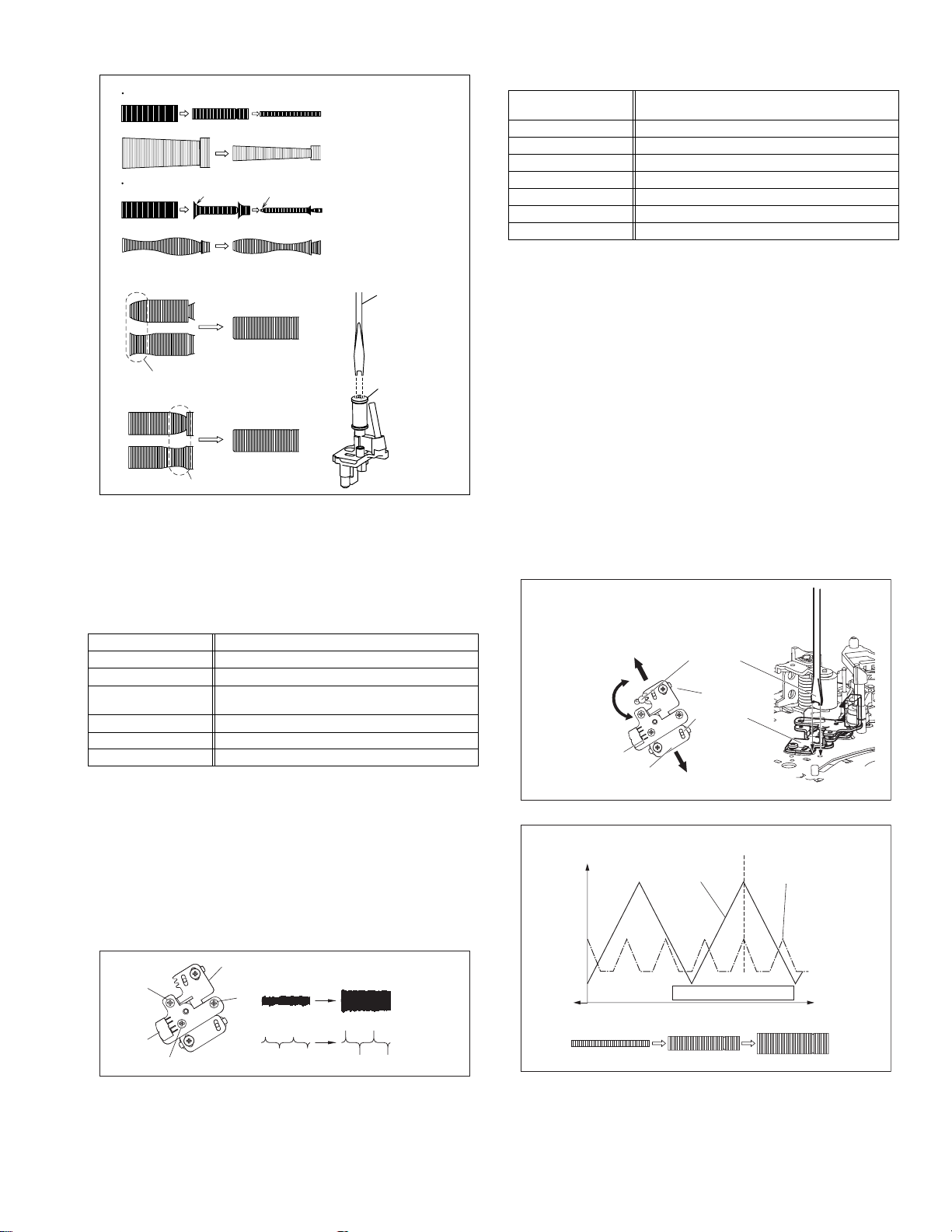
Proper waveform variation
Improper waveform variation
A
C
Up Down
B
D
Roller driver
Guide roller
(supply side)
Fig.4-2c
4.2.3 Height and tilt of the A/C head
Note:
• Set a temporary level of the height of the A/C head in ad-
vance to make the adjustment easier after the A/C head
has been replaced. (Refer to the SERVICE MANUAL
No.86700 [MECHANISM ASSEMBLY].)
Signal (A) • Alignment tape(SP, stairstep, NTSC) [MHP]
Mode (B) • PB
Equipment (C) • Oscilloscope
Measuring point (D1)
External trigger (E) • TP111 (D.FF)
Adjustment part (F) • A/C head [Mechanism assembly]
Specified value (G) • Maximum waveform
• TP106 (PB. FM)
(D2)
• TP4001 (CTL. P)
(1) Play back the alignment tape (A).
(2) Apply the external trigger signal to D.FF (E), to observe the
AUDIO OUT waveform and Control pulse waveform at the
measuring points (D1) and (D2) in the ALT mode.
(3) Set the VCR to the manual tracking mode.
(4) Adjust the AUDIO OUT waveform and Control pulse wave-
form by turning the screws (1), (2) and (3) little by little until
both waveforms reach maximum. The screw (1)
and (3) are for adjustment of tilt and the screw (2) for azi-
muth.
Head base
(2)
(1)
AUDIO OUT
4.2.4 A/C head phase (X-value)
Signal (A1)
Mode (B) • PB
Equipment (C) • Oscilloscope
Measuring point (D) • TP106 (PB. FM)
External trigger (E) • TP111 (D.FF)
Adjustment part (F) • A/C head base [Mechanism assembly]
Specified value (G) • Flat V.PB FM waveform
Adjustment tool (H) • Roller driver [PTU94002]
• Alignment tape(SP, stairstep, NTSC) [MHP]
(A2)
• Alignment tape(EP,stairstep,NTSC) [MHP-L]
(1) Play back the alignment tape (A1).
(2) Apply the external trigger signal to D.FF (E), to observe the
V.PB FM waveform at the measuring point (D).
(3) Set the VCR to the manual tracking mode.
(4) Loosen the screws (4) and (5), then set the Roller driver to
the innermost projected part of the A/C head. (See Fig. 4-
2e.)
(5) Rotate the roller driver so that the A/C head comes closest
to the capstan. From there, move the A/C head back grad-
ually toward the drum until the point where the FM wave-
form is maximized for the second time, and then
tighten the screws (4) and (5) temporarily.
(6) Play an alignment tape (A2) and set to the manual-tracking
mode.
(7) Fine-adjust A/C head base position to maximize the FM
waveform, and then tighten the screws (4) and (5) firmly.
(8) Play alignment tapes (A1) and (A2) and confirm that the FM
waveforms are maximized when the tracking is at the cen-
ter position.
To the drum
Toward the capstan
Toward the drum
A/C head
Screw (5)
Roller driver
Screw (4)
Head base
To the capstan
Fig.4-2e
Alignment tape
[SP, stairstep]
played with the
SP head
Waveform output
X-value adjustment point
Drum side Control head position Capstan side
Alignment tape
[EP(LP), stairstep]
played with the
EP(LP) head
A/C head
(3)
Fig.4-2d
CTL. P
Maximum
Fig.4-2f
(No.YD008)1-17
Page 18
4.3 Electrical adjustmen t (VHS SEC TION)
Note:
The following adjustment procedures are not only necessary
after replacement of consumable mechanical parts or board
assemblies, but are also provided as references to be referred
to when servicing the electrical circuitry.
In case of trouble with the electrical circuitry, always begin a
service by identifying the defective points by using the measuring instruments as described in the following electrical adjustment procedures. After this, proceed to the repair,
replacement and/or adjustment. If the required measuring instruments are not available in the field, do not change the adjustment parts (variable resistor, etc.) carelessly.
4.3.1 Servo circuit
4.3.1.1 Switching point
Signal (A1)
Mode (B) • PB
Equipment (C) • Oscilloscope
Measuring point (D) • VIDEO OUT terminal (75 ohm terminated)
External trigger (E) • TP111 (D.FF)
Adjustment part (F) • Jig RCU: Code “5A”
Specified value (G) • 6.5 ± 0.5H
Adjustment tool (H) • Jig RCU [PTU94023B]
• Stairstep signal
(A2)
• Alignment tape(EP,stairstep,NTSC) [MHP-L]
• TP106 (PB. FM)
(1) Play back the signal (A1) of the alignment tape (A2).
(2) Apply the external trigger signal to D.FF (E) to observe the
VIDEO OUT waveform and V.PB FM waveform at the
measuring points (D1) and (D2).
(3) Set the VCR to the manual tracking mode.
(4) Adjust tracking so that the V.PB FM waveform becomes
maximum.
(5) Set the VCR to the Auto adjust mode by transmitting the
code (F) from the Jig RCU. When the VCR enter s the sto p
mode, the adjustment is completed.
(6) If the VCR enters the eject mode, repeat steps (1) to (5)
again.
(7) Play back the alignment tape (A2) again, confirm that the
switching point is the specified value (G).
4.3.1.2 Slow tracking preset
Signal (A1)
Mode (B1)
Measuring point (D) • TV-Monitor
Adjustment part (F) • Jig RCU: Code “71”or “72”
Specified value (G) • minimum noise
Adjustment tool (H) • Jig RCU [PTU94023B]
• Ext. input
(A2)
• Color (colour) bar signal [NTSC]
• VHS SP
(B2)
•VHS EP
(1) Record the signal (A2) in the mode (B1), and play back
the recorded signal.
(2) Set the VCR to the manual tracking mode.
(3) Set the VCR to the FWD slow (+1/6x) mode.
(4) Transmit the code (F) from the Jig RCU to adjust so that the
noise bar becomes the specified value (G) on the TV
monitor in the slow mode.
(5) Set the VCR to the Stop mode.
(6) Confirm that the noise b ar is (G) on the TV monitor in the
slow mode.
(7) Repeat steps (3) to (6) in the REV slow (+1/6x) mode.
(8) Repeat steps (1) to (7) in the mode (B2).
Note:
• For FWD slow (+1/6x) playback, transmit the code “08”
from the Jig RCU to enter the slow playback mode, and
transmit the code “D0”for REV slow (-1/6x) mode.
Trigger point
1-18 (No.YD008)
Switching point
V.sync
V. rate
Fig.4-3a Switching point
Page 19
4.4 Electrical adjustment (DVD SECTION)
4.4.1 Test mode setting method
(1) Press POWER button to turn off the unit.
(2) Press the following remocon keys continuously within 2seconds " SET UP " → " 2 " → " 8 " → " ENTER ".
(3) The unit becomes JIG RCU mode.
(4) Press POWER button then press VCR/DVD repeatedly so that the DVD indicatorlights up.
(5) Press the POWER button again to turn off the unit.
(6) Transmit the code " FA " from the Jig RCU.
(7) The power supply of the unit turns on automatically th en the FDP shows the region number.
(8) To release test mode, press POWER key of the front panel.
VCR
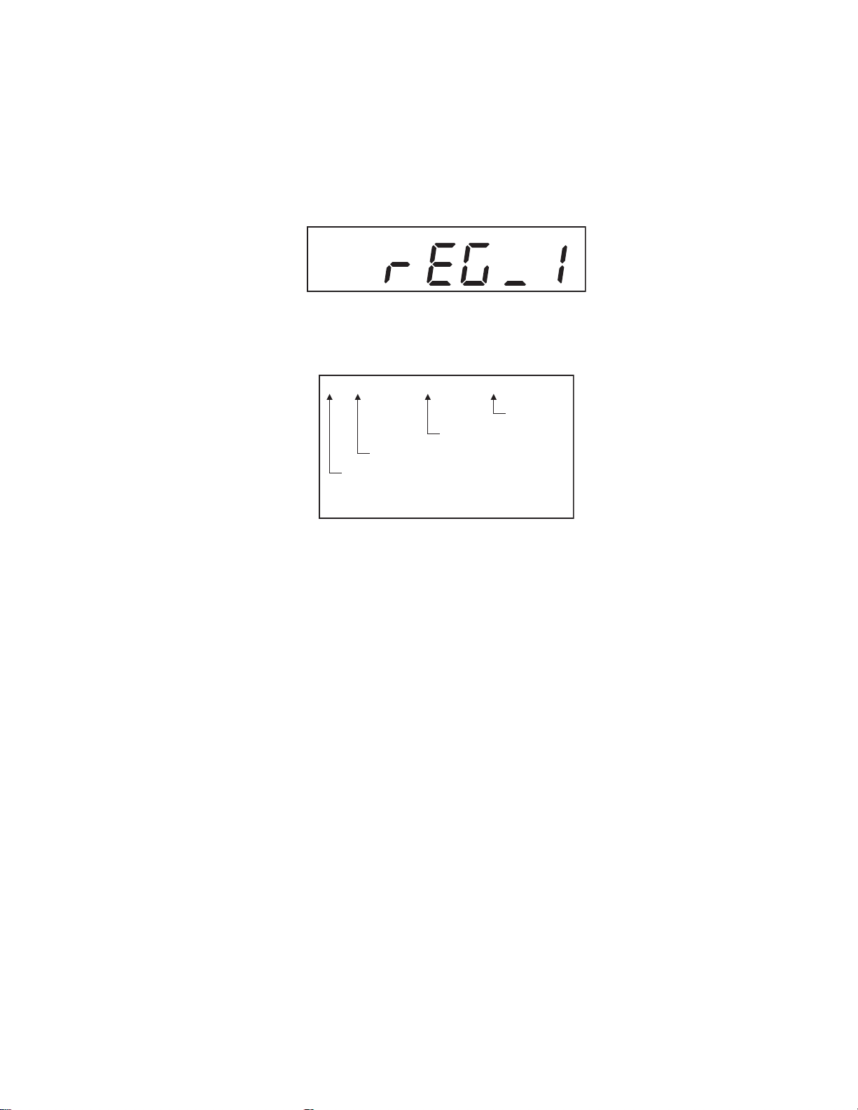
4.4.2 Method of displayed version of firmware
(1) Set the unit to the test mode.
(2) The version number is displayed in the monitor screen.
OPENING DISPLAY
**_Ver.****_HS/HR_XVC26US/*******
Others
Model name
Version of firmware
Destination
4.4.3 Initialization method
Please initialize according to the following procedures in the following case:
• Just after you upgrade the firmware.
• After you confirm the symptoms that a customer points out. First Initialize, and then confirm whether the symptoms are improved or
not.
• After servicing, before returning the main body to a customer. (Initialized unit should be returned to a customer.)
(1) Set the unit to the test mode.
(2) Press PAUSE key of the remote controller or transmit the code "6F" from the Jig RCU.
(3) When initialization is completed, the PLAY (). mark is indicated in the FDP.
4.4.4 All-initialization method
Please perform all-initialization according to the following procedures in the following case:
• Just after you exchange the pick-up.
• Just after you exchange the spindle motor.
• Just after you exchange the traverse mechan i sm ba se .
NOTE:
Please perform all-initialization when you exchange the parts above and also when you remove the parts above.
(1) Set the unit to the test mode.
(2) Press the REVERSE SKIP/INDEX () key of the remote controller for more than 2 seconds.
(3) When initialization is completed, the PLAY (). mark is indicated in the FDP.
NOTE:
After all-initialization, be sure to perform optimization adjustment of Front End parameter.
(No.YD008)1-19
Page 20
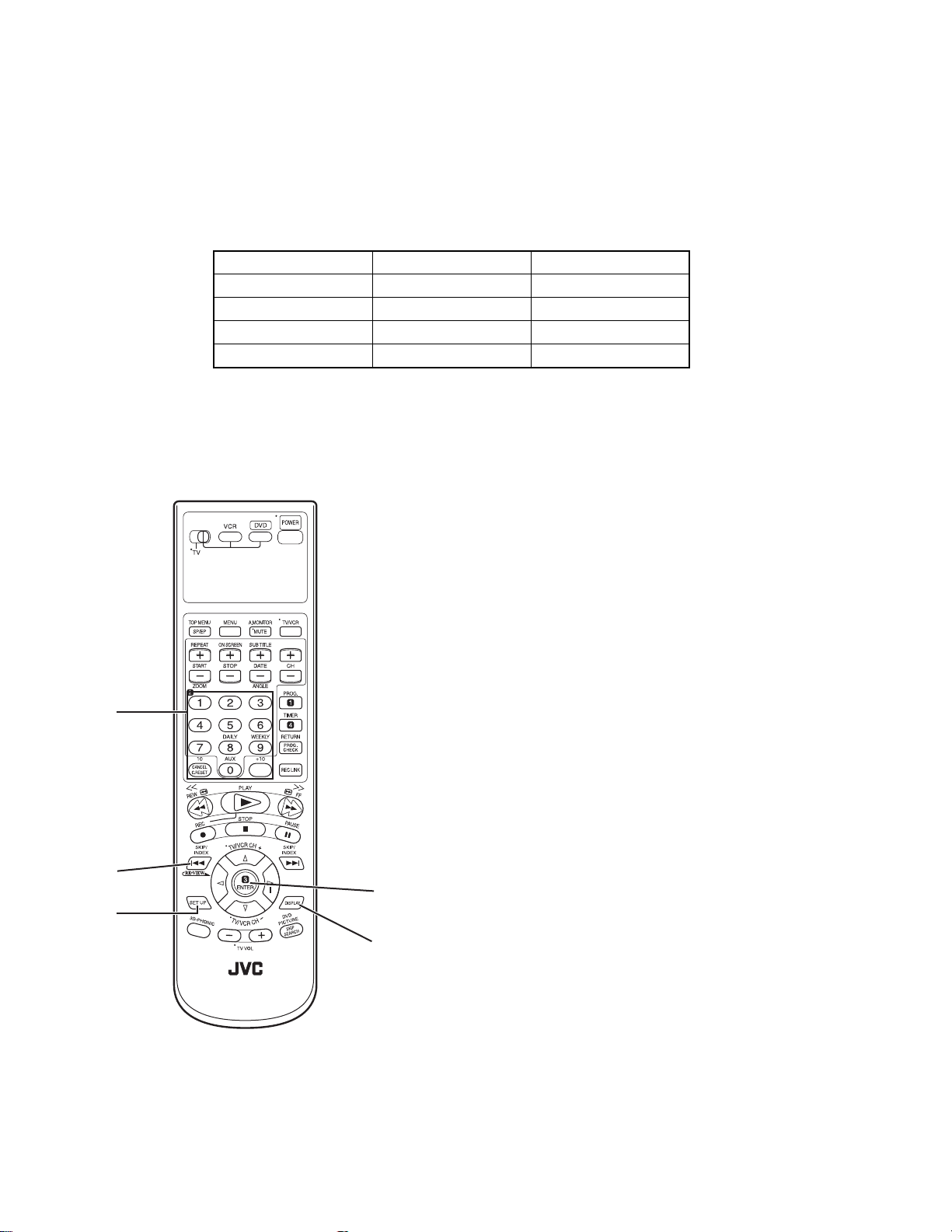
4.4.5 Optimization adjustment of Front End parameter
Adjustment to optimize Front End parameter must be performed in each mechanism assembly of this model for h igh-speed starting.Please perform optimization according to the following procedu res just after all-initialization is comp leted and when FDP shows
anything except "0" (For example when FDP shows "1", "2", and "3") at test mode.
(1) Set the unit to the test mode.
(2) The FDP shows the region number first.
(3) Press the DISPLAY key of the remote controller and check that FDP shows the number.
(4) Press the DISPLAY key again to return the region number.
NOTE:
Status of this adjustment can be judged by the number displayed at test mode as follows:
DVD adjustment CD adjustment FDP at test mode
Adjusted Adjusted 0
Not adjusted Adjusted 1
Adjusted Not adjusted 2
Not adjusted Not adjusted 3
NOTE:
As for a disc used for adjustment,
• Disc should be mounted. ("Mounting" means to display "READ" after the disc is inserted and then display the disc information.) Disc need not be played.
• If you do not have test disc either VT-501 (DVD) or CTS-1000 (CD-DA), use a commercial disc (for DVD, dual-layer software) after seeing and checking that the disc is neither curved nor foreseen that it may shake at the time of playback.If you
use a disc with bad features, starting time may be slow or disc may not be read.
NUMBER
KEYS
REVERSE
SKIP/INDEX
SET UP
ENTER
DISPLAY
1-20 (No.YD008)
Page 21
SECTION 5
TROUBLESHOOTING
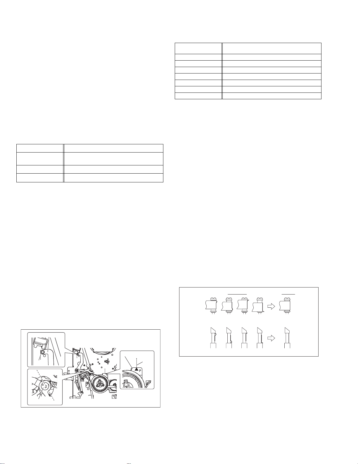
5.1 Manually removing the cassette tape
If you cannot remove the cassette tape which is loaded because
of any electrical or mechanical failures, manually remove it by
taking the following steps.
(1) Unplug the power cord plug from the power outlet.
(2) Refer to the disassembly procedure of the VCR and per-
form the disassembly of the major parts before removing
the mechanism assembly. (See Fig. 5-1a)
Fig.5-1a
Tension arm assembly
Pole base assembly
Pinch roller arm assembly
(3) Unload the pole base assembly by manually turnin g the
gear of the loading motor until the pole base assembly is
hidden behind the cassette lid. In doing so, hold the tape by
the hand to keep the slack away from any grease. (See
Fig.5-1b )
In case of mechanical failures, while keeping the tension arm assembly free from tension, pull out the tape
on the pole base assembly. Take the spring(a) of the
pinch roller arm assembly off the hook, and detach it
from the tape.
(4) Remove the screw (a) of the side frame (L/R).
(5) Hold the slack tape and cassette cover together, lift the
cassette tape, top frame, cassette holder and side frames
(L, R) together from the rear and remove them by dis-engaging the hooks (a) and (b).
Screw(a)
Cassette tape
Hook(a)
Cassette holder
Top frame
Side frame(R)
Screw(a)
Spring(a)
Direction of unloading
Fig.5-1b
Side frame(L)
Hook(b)
Fig.5-1c
(6) Take up the slack of the tape into the cassette. This com-
pletes removal of the cassette tape.
5.2 Manually remo ving the disk(DVD/CD)
If you cannot remove the disk which is loaded because of any
electrical or mechanical failures, manually remove it by taking the
following steps.
(1) Unplug the power cord plug from the power outlet.
(2) Remove the top cover and front panel assembly.
(Refer to the disassembly procedure and perform the disassembly of the major parts before removing)
(3) Turn the Middle gear (a) by hand to open the disk tray.(See
Fig. 5-2a)
DVD unit
Middle gear (a)
Unloading
Fig.5-2a
(No.YD008)1-21
Page 22
5.3 Emergency display function (VHS SECTION)
This unit saves details of the last two emergencies as the EMG
history and allows the status of the VCR and the mechanism of
each emergency to be shown both on the display and as OSD information.
When using the emergency function, it is required to set the VCR
to the Jig RCU mode.
Jig RCU
[Data transmitting method]
Depress the " " ( 3 ) button
after the data code is set.
CUSTOM CODE
43: A CODE
DATA CODE
INITIAL MODE
Fig.5-3a Jig RCU [PTU94023B]
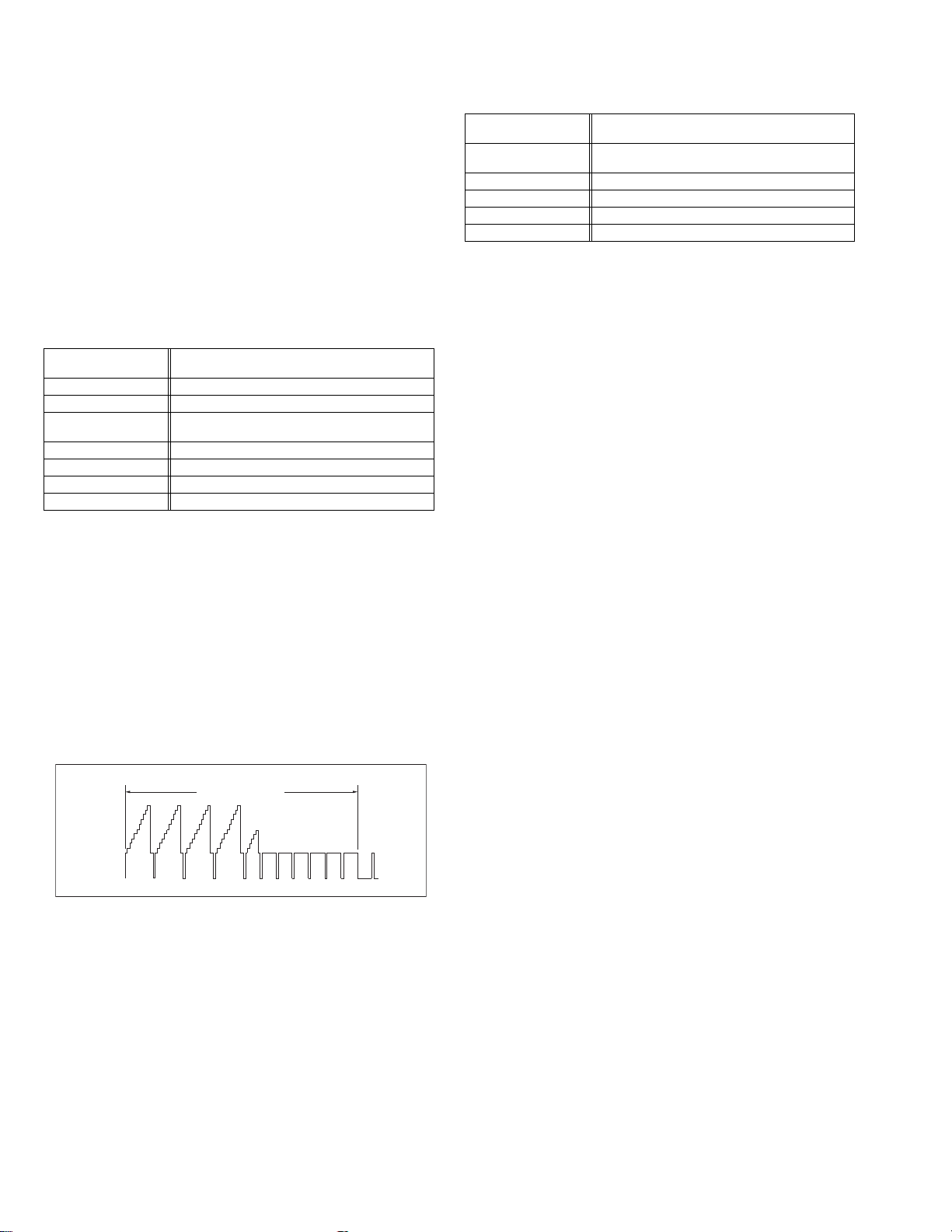
5.3.1 Displaying the EMG information
The EMG detail of information can be displayed by transmitting
the code "59" from the Jig RCU.
Note:
• The EMG detail information <1><2> show the informa-
tion on the latest EMG.
It becomes “ - - : - - : - - ” when there is no latest EMG
record.
0: 00
E: **
1E: **
1: *1
2: *2
3: 34
4: *5
5: *6
6: *7
7: *8
8: *9
9: *10
Normal display
EMG content display (Latest) See 5.3.4
EMG content display (Previous) See 5.3.4
EMG detail information <1> See 5.3.5
[Deck operation mode]
EMG detail information <1> See 5.3.5
[Mechanism operation mode]
EMG detail information <1> See 5.3.5
[Mechanism sensor information and Mechanism mode position]
EMG detail information <2> See 5.3.6
[Type of the cassette tape in use <1>]
EMG detail information <2> See 5.3.6
[Winding position of the cassette tape in use]
EMG detail information <2> See 5.3.6
[Type of the cassette tape in use <2> (Winding area)]
EMG detail information <3> See 5.3.7
[Previous deck operation mode]
EMG detail information <3> See 5.3.7
[The deck operation mode of the one before the last]
EMG detail information <3> See 5.3.7
[The deck operation mode of the one prior to one above]
EMG display of 7 FDP display model
Fig.5-3b
EMG display of FDP display mode
(1) Transmit the code “59” from the Jig RCU.
The FDP shows the EMG content in the form of “E:**:**”.
<Example 1> E : 01
Latest EMG
<Example 2> E : - -
No EMG record
(2) Transmit the code “59” from the Jig RCU again.
The FDP shows the EMG detail information <1> in the form
of “ *1: *2 : 34 ”.
*1 : Deck operation mode at the moment of EMG
*2 : Mechanism operation mode at the moment of EMG
3- : Mechanism sensor information at the moment of EMG
-4 : Mechanism mode position at the moment of EMG
(3) Transmit the code “59” from the Jig RCU once again.
The FDP shows the EMG detail information <2> in the form
of “ *5 : *6 : *7 ”.
*5 : Type of the cassette tape in use <1> .
*6 : Winding position of the cassette tape in use
*7 : Type of the cassette tape in use <2> (Winding area)
(4) Transmit the code “59” from the Jig RCU once again.
The FDP shows the EMG detail information <3> in the form
of “*8 : *9 : *10”.
*8 : Previous deck operation mode at the moment of EMG
*9 : The deck operation mode of the one before the last at
the moment of EMG
*10: The deck operation mode of the one prior to one
above at the moment of EMG
(5) Transmit the code “59” from the Jig RCU once again to re-
set the display.
1-22 (No.YD008)
Page 23
5.3.2 Clearing the EMG history
(1) Display the EMG history.
(2) Transmit the code “36” from the Jig RCU.
(3) Reset the EMG display.
5.3.3 Details of the OSD display in the EMG display mode
During the EMG display, the OSD shows the data on the deck
mode, etc. The details of the display contents are as follows.
Notes:
• The display is variable depending on the part No. of the
System Control microcomputer (IC3001) built into the
VCR. In the following, refer to the figure carrying the
same two characters as the top two character s of the
part number of your IC.
• The sensor information in the OSD display contents is
partially different from the mechanism sensor information in EMG detail information <1>.
[For MN* only]
AA BB CC DD EE
FF GG HH I I J J
KK LL MM NN OO
PP QQ RR SS TT
UU VV WW XX YY
AA : Deck operation mode (See EMG detail information <1>.)
BB : Mechanism operation mode
(See EMG detail of information <1>.)
CC : Mechanism transition flag
DD : Capstan motor control status
EE : Loading motor control status
FF : Sensor information (See sensor information details.)
GG : Capstan motor speed
HH : Key code (JVC code)
I I : Supply reel winding diameter data higher 8 bits.
JJ : Supply reel winding diameter data lower 8 bits.
KK : Mechanism sensor information & mechanism mode posi-
tion(See EMG detail of information <1>.)
LL : Tape speed data higher 8 bits.
MM : Tape speed data lower 8 bits.
NN : Cassette tape type <2> higher 8 bits.
(See EMG detail of information <2>.)
OO : Cassette tape type <2> lower 8 bits.
(See EMG detail of information <2>.)
PP : General data display area
YY : General data display area
*FF:Sensor information details
<Display>
** h
********
Encoder data
(See Mechanism mode sequence.)
Cassette tab present = 1
Cassette tab broken = 0
Cassette absent = 1
Cassette present = 0
Start sensor
End sensor
[For *HD only]
AA BB CC
DD EE FF
GGGG HHHH
I I JJJJ
KKKK LLLL MMMM
ROM No.
AA : Key code (JVC code)
BB : Deck operation mode(See EMG detail information
<1>.)
CC : Mechanism operation mode (See EMG detail informa-
tion <1>.)
DD : Sensor information (See sensor information details.)
EE : Capstan motor speed (Search, double speed)
FF : Tracking value
GGGG : Cassette tape type <2>, 16 bits.
(See EMG detail information <2>.)
HHHH : Supply reel winding diameter data
I I : Capstan motor speed (FF/REW, double speed)
JJJJ : Tape speed data, lower 8 bits.
KKKK : General data display area
LLLL : General data display area
MMMM : General data display area
*DD:Sensor information details
<Display>
** h
********
Encoder data
(See Mechanism mode sequence.)
Remote pause
End sensor
Start sensor
Cassette tab present = 1
Cassette tab broken = 0
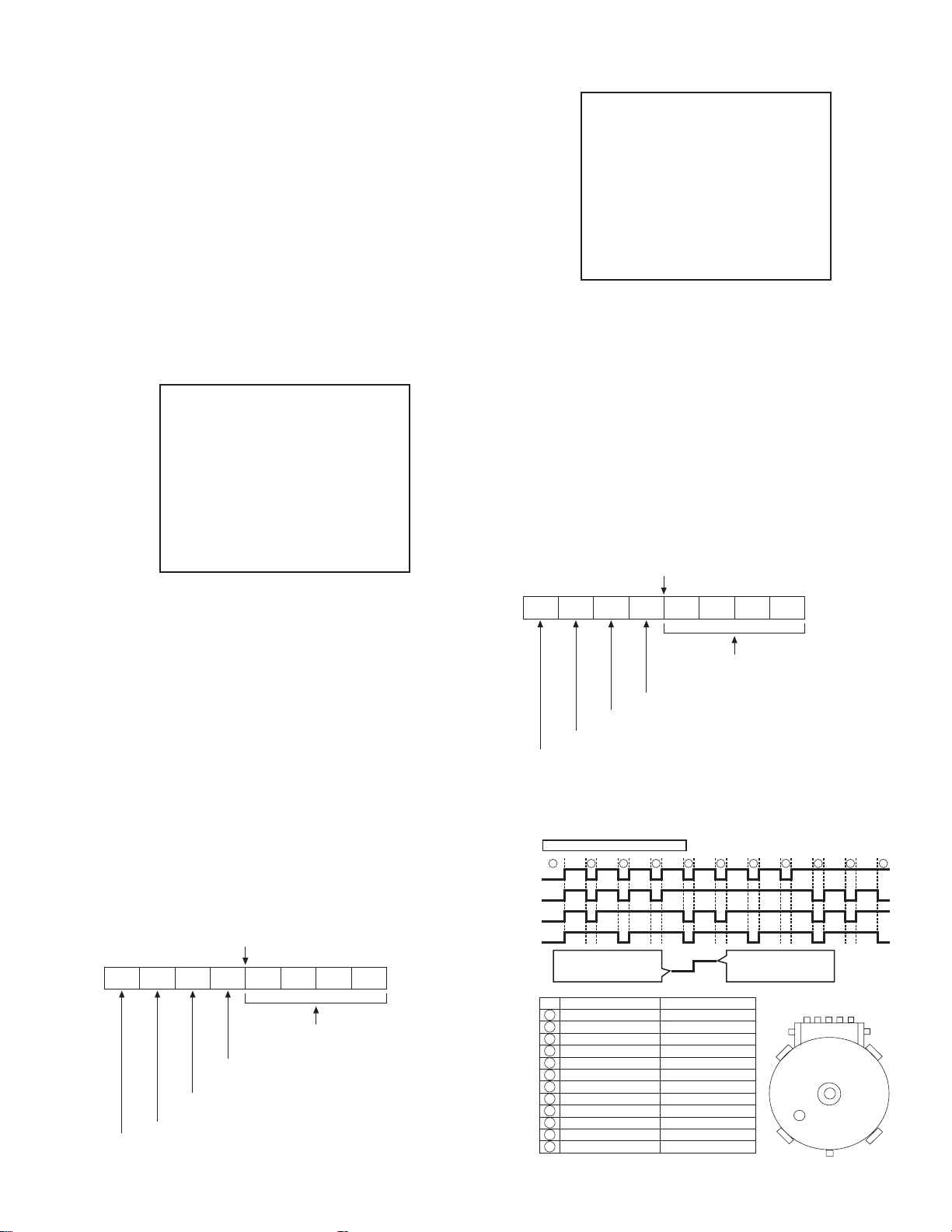
[For both MN*/HD*]
Mechanism mode sequence
Mechanism mode - Encoder data
LSA
12345
1110
GND
LSA
LSB
LSC
LSD
No. Position Encoder data
21
Encoder output = Low
or
Trerminal - GND = SHORT
1
EJECT 0 h = 0000
2
EJECT1 1 h = 0001
3
EJECT2 2 h = 0010
4
ULSTOP 3 h = 0011
5
UPPER 4 h = 0100
6
ONSTOP(PLAY) 5 h = 0101
7
FWD/SS 6 h = 0110
8
REV/SS 7 h = 0111
9
OFFSTOP 8 h = 1000
10
FFREW-BRAKE 9 h = 1001
FFREW A h = 1010
11
MIDDLE F h = 1111
12
543
Encoder output = High
or
Trerminal - GND = OPEN
LSD
9876
LSC
LSB
(No.YD008)1-23
Page 24

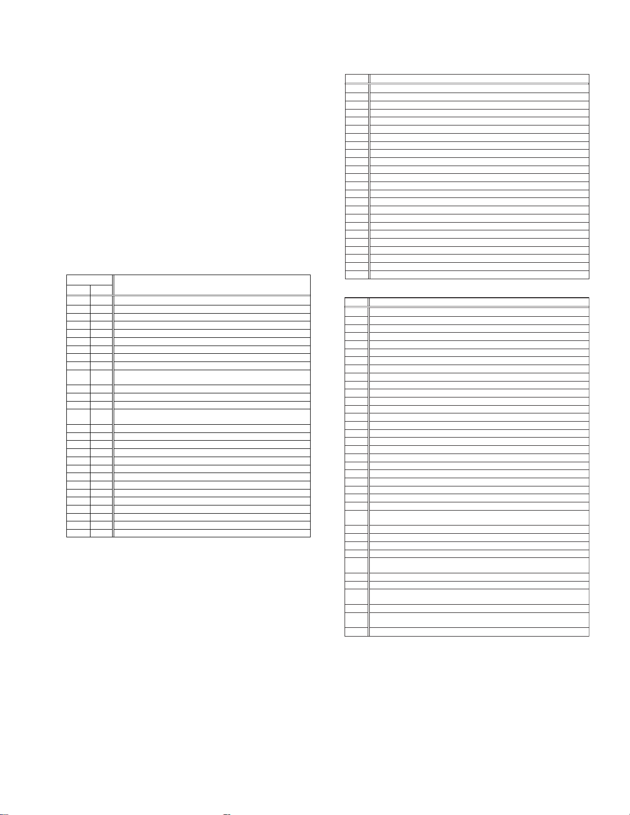
5.3.4 EMG content description
Note:
EMG contents “E09” are for the model with Dynamic Drum (DD).
FDP CONTENT CAUSE
E01: Loading EMG
E02:
Unloading EMG
E03: Take Up Reel
Pulse EMG
E04: Drum FG EMG
E05: Cassette Eject
EMG
E06: Capstan FG
EMG
E07: SW Power
Short-Circuit
EMG
E08:
DVD EMG
E09: DD FG EMG
E0A: Supply Reel
Pulse EMG
EU1:
Head clog warning
history
If the mechanism mode does not change to the next mode within 4 seconds after the loading motor starts rotating in the loading direction, while
the mechanism is in the after-loading position (with the tape up against
the pole base), [E:01] is identified and the power is switched OFF.
However, if the tape loading is not completed within 4 seconds after
the loading motor starts rotating in the loading direction, the tape is
simply unloaded and ejected. No EMG data is recorded in this case.
When the mechanism mode cannot be changed to another mode
even when the loading motor has rotated for more than 4 seconds in the unloading direction, [E:02] is identified and the power
is turned off.
When the falling edje of the take-up reel pulse has not been generated for more than 4 seconds in the capstan rotating mode,
[E:03] is identified, the pinch rollers are turned off and stopped,
and the power is turned off. In this case, however, the mechanism should be in position after tape loading. Note that the reel
EMG is not detected during Slow/Frame advance operations.
When the drum FG pulse has not been input for more than 3 seconds in the drum rotating mode, [E:04] is identified, the pinch rollers are turned off and stopped, and the power is turned off.
If the cassette does not reach the eject position within about 0.7
seconds after the cassette housing has started the cassette ejection operation, [E:05] is identified, the drive direction is reversed
to load the tape, the mode is switched to STOP mode with the
pinch roller OFF, and the power is switched OFF.
During the cassette insertion process, the drive direction is reversed
and the cassette is ejected if the tape is not up against the pole
base within about 3 seconds after the start of the cassette pullingin operation. If the cassette does not reach the eject position within
about 0.7 seconds after the drive mode reversal operation, [E:05]
is identified and the power is switched OFF immediately.
When the capstan FG pulse has not been generated for more
than 1 second in the capstan rotating mode, [E:06] is identified,
the pinch rollers are turned off and stopped, and the power is
turned off.However, the capstan EMG is not detected in SLOW/
STILL modes.
Note that, if the part number of the System Control IC begins with
"MN" or "M3", the capstan EMG is not detected even during the
FF/REW operation.
When short-circuiting of the SW power supply with GND has lasted
for 0.5 second or more, [E:07] is identified, all the motors are
stopped and the power is turned off.
When communication with a system computer of VHS side is not
carried out because of the defective DVD unit, or when the DVD
unit must be reset
When the DD FG pulse is not generated within 2.5 seconds, [E:09]
is identified, the tilt motor is stopped and the power is turned off.
When the falling edge of the supply reel pulse has not been generated for more than 10 seconds in the capstan rotating mode,
[E:0A] is identified and the cassette is ejected (but the power is
not turned off). In this case, however, the mechanism should be
in the position after tape loading (with the tape up against the pole
base). Also note that the reel EMG is not detected during Slow/
Frame advance operations.
Presupposing the presence of the control pulse output in the PLAY mode, when the value obtained by mixing the two V.FM output channels (without regard
to the A.FM output) has remained below a certain threshold level for more than 10 seconds, [E:U1] is identified and recorded in the emergency history.
During the period in which the head clog is detected, the FDP shows "U:01" and the OSD repeats the "3 seconds of warning display" and the "7 seconds of
noise picture display" alternately.
EMG code : "E:C1" or "E:U1" / FDP : "U:01" / OSD : "Try cleaning tape." or "Use cleaning cassette."
The head clog warning is reset when the above-mentioned threshold has been exceeded for more than 2 seconds or the mode is changed to another mode
than PLAY.
1. The mechanism is locked in the middle of the mode transition during a tape loading operation.
2.
The mechanism overruns during the tape loading operation because the SYSCON cannot recognize
the mechanism mode normally. This problem is due to a cause such as a rotary encoder failure.
3.
Power is not supplied to the loading MDA. (M12V/Vcc/Vref/ICP are disconnected in the middle.)
1.
The mechanism is locked in the middle of mode transition.
2.
Without an eject signal being sent from the SYSCON, unloading is attempted (i.e. Ejection is attempted
while the tape is still inside the mechanism.) because the SYSCON cannot recognize the mechanism
mode normally. This is due to a cause such as a rotary encoder failure. (Mechanism position:
UPPER)
3.
Power is not supplied to the loading MDA. (M12V/Vcc/Vref/ICP are disconnected in the middle.)
1.
The take-up reel pulse is not generated in the FWD transport modes (PLAY/FWD SEARCH/FF,
etc.) because;
1) The idler gear is not meshed with the take-up reel gear because the mechanism mal-functions for
2)
3) The reel is rotating normally but an FG pulse is not generated due to the take-up reel sensor failure.
2.
The supply reel pulse is not generated in the REV transport modes (REV SEARCH/REW, etc.)
because;
1) The idler gear is not meshed with the supply reel gear because the mechanism mal-functions for
2) The idler gear is meshed with the supply reel gear, but incapable of winding due to too large a
3) The reel rotates normally but the FG pulse is not generated due to a supply reel sensor failure.
3.
Power(SW5V) is not supplied to the reel sensor on the tape winding side.
1.
The drum could not start or the drum rotation has stopped due to too large a load on the tape,
because;
1) The tape tension is abnormally high;
2) The tape is damaged or a foreign object (grease, etc.) adheres to the tape.
2.
The drum FG pulse did not reach the System controller CPU because;
1) The signal circuit is disconnected in the middle;
2) The FG pulse generator (hall device) of the drum is faulty.
3.
The drum control voltage (DRUM CTL V) is not supplied to the MDA.
4.
Power (M12V) is not supplied to the drum MDA.
1.
The cassette cannot be ejected due to a failure in the drive mechanism of the housing.
2.
When the housing load increases during ejection, the loading motor is stopped because of lack of
headroom in its drive torque.
3.
The sensor/switch for detecting the end of ejection are not functioning normally.
4.
The loading motor drive voltage is lower than specified or power (M12V) is not supplied to the
motor (MDA).
5.
When the user attempted to eject a cassette, a foreign object (or perhaps the user's hand) was
caught in the opening of the housing.
1.
The capstan could not start or the capstan rotation has stopped due to too large a load on the tape,
because;
1) The tape tension is abnormally high (mechanical lock);
2) The tape is damaged or a foreign object (grease, etc.) is adhered to the tape (occurrence of tape
2.
The capstan FG pulse did not reach the System controller CPU because;
1) The signal circuit is disconnected in the middle;
2) The FG pulse generator (MR device) of the capstans is faulty.
3.
The capstan control voltage (CAPSTAN CTL V) is not supplied to the MDA.
4.
Power (M12V, SW5V) are not supplied to the capstan MDA.
1.
The SW 5 V power supply circuit is shorted with GND.
2.
The SW 12 V power supply circuit is shorted with GND.
1. The DVD unit is defective.
2. Contact failure of the wires in the DVD unit or VHS side.
1. The FG sensor is defective. (The soldered parts have separated.)
2. The pull-up resistor at the FG sensor output is defective. (The soldered parts have separated.)
3. Contact failure or soldering failure of the pins of the connector (board-to-board) to the FG sensor.
4. The power (5V) to the sensor is not supplied. (Connection failure/soldering failure)
5. The FG pulse is not sent to the System Controller CPU.
6.
The tilt motor is defective. (The soldered parts have separated.)
7. The drive power to the tilt motor is not supplied. (Connection failure/soldering failure)
8. The tilt motor drive MDA - IC is defective.
9. Auto-recovery of the DD tilting cannot take place due to overrun.
1.
The supply reel pulse is not generated in the FWD transport mode (PLAY/FWD SEARCH/FF,
etc.) because;
1) PLAY/FWD or SEARCH/FF is started while the tape in the inserted cassette is cut in the middle;
2) A mechanical factor caused tape slack inside and outside the supply reel side of the cassette shell.
3) The reel is rotating normally but the FG pulse is not generated due to a supply reel sensor failure.
2.
The take-up reel pulse is not generated in the REV transport mode (REV SEARCH/REW, etc.).
1) REV SEARCH/REW is started when the tape in the inserted cassette has been cut in the middle;
2) A mechanical factor caused tape slack inside and outside the take-up reel side of the cassette
3) The reel is rotating normally but the FG pulse is not generated due to a take-up reel sensor failure.
3.
The power (SW 5V) to a reel sensor is not supplied.
some reason.
The idler gear is meshed with the take-up reel gear, but incapable of winding due to too large
mechanical load (abnormal tension);
some reason.
mechanical load (abnormal tension);
Housing load increasing factors: Temperature environment (low temperature, etc.), mechanism
wear or failure.
entangling, etc.).
In this case, the supply reel will not rotate until the tape slack is removed by the FWD transport,
so the pulse is not generated until then;
shell. In this case, the take up will not rotate until the tape slack is removed by the REV transport,
so the pulse will not be generated until that time;
1-24 (No.YD008)
Page 25
5.3.5 EMG detail information <1>
The status (electrical operation mode) of the VCR and the status
(mechanism operation mode/sensor information) of the mechanism in the latest EMG can be confirmed based on the figure in
EMG detail information <1> .
[FDP/OSD display] *1 : *2 : 34
*1 : Deck operation mode at the moment of EMG
*2 : Mechanism operation mode at the moment of EMG
3- : Mechanism sensor information at the moment of EMG
-4 : Mechanism mode position at the moment of EMG
Note:
• For EMG detailed information <1>, the content of the
code that is shown on the display (or OSD) differs depending on the parts number of the system control microprocessor (IC3001) of the VCR. The system control
microprocessor parts number starts with two letters, refer these to the corresponding table.
*1 : Deck operation mode
[Common table of MN* and HD]
Display
MN* HD*
00 - Mechanism being initialized
01 00 STOP with pinch roller pressure off (or tape present with P.OFF)
02 01 STOP with pinch roller pressure on
03 - POWER OFF as a result of EMG
04 04 PLAY (Normal playback)
0C 0E REC
10 11 Cassette ejected
20 22 FF
21 - Tape fully loaded, START sensor ON, short FF
22 -
24 26 FWD SEARCH (variable speed) including x2-speed
2C 2E INSERT REC
40 43 REW
42 - Cassette identification REV SEARCH before transition to REW
44 47 REV SEARCH (variable speed)
4C 4C AUDIO DUB
6C 6E INSERT REC (VIDEO + AUDIO)
84 84 FWD STILL / SLOW
85 85 REV STILL / SLOW
8C 8F REC PAUSE
8D - Back spacing
8E - Forward spacing (FWD transport mode with BEST function)
AC AF INSERT REC PAUSE
AD - INSERT REC back spacing
CC CD AUDIO DUB PAUSE
CD - AUDIO DUB back spacing
EC EF INSERT REC (VIDEO + AUDIO) PAUSE
ED - INSERT REC (VIDEO + AUDIO) back spacing
Cassette identification FWD SEARCH before transition to FF
(SPx7-speed)
(SPx7-speed)
Deck operation mode
*2 : Mechanism operation mode
[Table of MN*]
Display
00 Command standby (No command to be executed)
01 Immediate Power OFF after EMG occurrence
02 Loading from an intermediate position during mechanism initialization
03 Unloading due to EMG occurrence during mechanism initialization
04 Ejecting cassette (ULSTOP to EJECT)
05 Inserting cassette (EJECT to ULSTOP)
06 Loading tape (ULSTOP to PLAY)
07 Unloading tape (PLAY to ULSTOP)
08 Transition from pinch roller ON to STOP
09 Transition from pinch roller OFF to STOP (PLAY to OFFSTOP)
0A Transition from pinch roller OFF to STOP at power OFF
0B Transition from pinch roller ON to STOP at power ON
0C Transition to PLAY
0D Transition to Search FF
0E Transition to REC
0F Transition to FWD STILL/SLOW
10 Transition to REV STILL/SLOW
11 Transition to Search REV
12 Transition from FF/REW to STOP
13 Transition to FF
14 Transition to REW
15 Tape end detection processing during loading
16 Short FWD/REV at tape sensor ON during unloading
17 Transition to FF/REW brake mode
Mechanism operation mode
[Table of HD*]
Display
00 STOP with pinch roller pressure off
01 STOP with pinch roller pressure on
02 U/L STOP (or tape being loaded)
04 PLAY (Normal playback)
05 PLAY (x1-speed playback using JOG)
0E REC
11 Cassette ejected
22 FF
26 FWD SEARCH (variable speed) including x2-speed
2E INSERT REC
43 REW
47 REV SEARCH
4C AUDIO DUB
6E INSERT REC (VIDEO + AUDIO)
84 FWD STILL/SLOW
85 REV STILL/SLOW
8F REC PAUSE
AF INSERT REC PAUSE
C7 REV SEARCH (x1-speed reverse playback using JOG)
CD AUDIO DUB PAUSE
EF INSERT REC (VIDEO + AUDIO) PAUSE
F0 Mechanism being initialized
F1 POWER OFF as a result of EMG
F2 Cassette being inserted
F3 Cassette being ejected
F4 Transition from STOP with pinch roller pressure on to STOP with pinch
roller pressure off
F5 Transition from STOP with pinch roller pressure on to PLAY
F6 Transition from STOP with pinch roller pressure on to REC
F7 Cassette type detection SEARCH before FF/REW is being executed
F8 Tape being unloaded
F9 Transition from STOP with pinch roller pressure off to STOP with pinch
roller pressure on
FA Transition from STOP with pinch roller pressure off to FF/REW
FB Transition from STOP with pinch roller pressure off to REC.P (T.REC,etc.)
FC Transition from STOP with pinch roller pressure off to cassette type
detection SEARCH
FD Short REV being executed after END sensor on during unloading
FE Tension loosening being executed after tape loading (STOP with pinch
roller pressure on)
FF Tape being unloaded
Mechanism operation mode
(No.YD008)1-25
Page 26
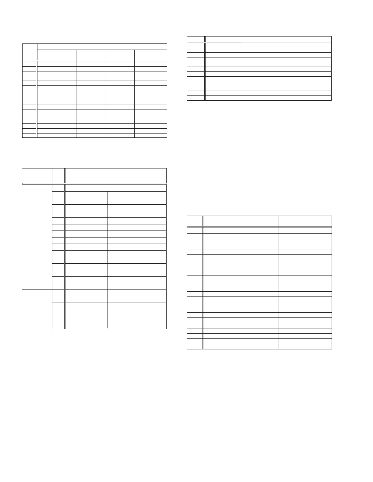
3- : Mechanism sensor information
[Common table of MN* and HD*]
Display
C- Tab present ON
D- Tab present
REC safety SW
0- Tab broken ON ON ON
1- Tab broken ON
2- Tab broken ON
3- Tab broken ON OFF
4- Tab present ON
5- Tab present
6- Tab present OFF
7- Tab present OFF
8- Tab broken ON ON
9- Tab broken ON
A- Tab broken
B- Tab broken OFF
E- Tab present OFF
F- Tab present OFF
Tab broken = 0 Sensor ON = 0 Sensor ON = 0
Tab present = 1 sensor OFF = 1 Sensor OFF = 1
Mechanism sensor informatio n
Start sensor End sensor
ON
OFF
OFF
OFF
ON
ON
OFF
OFF
ON
OFF
OFF
ON
OFF
ON
OFF
OFF OFF
Mechansim
position sensor
OFF
ON
OFF
ON
OFF
ON
OFF
ON
OFF
ON
OFF
ON
OFF
ON
-4 : Mechanism mode position
[Common table of MN* and HD*]
Mechanism
sensor
information
Dis-
play
Deck operation mode
-0 Not established
-1 EJECT EJECT position
-2 EJECT-EJECT1 Intermodal position
-3 EJECT1 EJECT1 position
-4 EJECT1-EJECT2 Intermodal position
-5 EJECT2 EJECT2 position
-6 EJECT2-ULSTOP Intermodal position
Even number
(0, 2, 4, 6, 8,
A, C, E)
-7 ULSTOP ULSTOP position
-8 ULSTOP-UPPER Intermodal position
-9 UPPER Loading (unloading) tape
-A UPPER-ONSTOP Intermodal position
-B ONSTOP PLAY position
-C PLAY-FWD/SS Intermodal position
-D FWD/SS
FWD (FWD Still/Slow) position
-E FWD/SS-REV Intermodal position
-F REV
REV (REV Still/Slow) position
-0 REV-OFFSTOP Intermodal position
-1 OFFSTOP Pinch roller OFF position
Odd number
(1, 3, 5, 7, 9,
B, D, F)
-2
OFFSTOP-FFREWB
Intermodal position
-3 FFREWB FF/REW Brake position
-4 FFREWB-FFREW Intermodal position
-5 FFREW FF/REW position
5.3.6 EMG detail information <2>
The type of the cassette tape and the cassette tape winding position can be confirmed based on the figure in EMG detail information <2> .
Note:
• EMG detail information <2> is the reference information
stored using the remaining tape detection function of
the cassette tape. As a result, it may not identify ca ssette correctly when a special cassette tape is used or
when the tape has variable thickness.
*5 : Cassette tape type <1>
Display Cassette tape type <1>
00 Cassette type not identified
16
Large reel/small reel (T-0 to T-15/T-130 to T-210) not classified
82 Small reel, thick tape (T-120) identified/thin tape (T-140) identified
84 Large reel (T-0 to T-60) identified
92
Small reel, thick tape (T-130) identified/thin tape (T-160 to T-210) identified
93
Small reel, thick tape/C cassette (T-0 to T-100/C cassette) not classified
C3
Small reel, thick tape/C cassette (T-0 to T-100/C cassette) being classified
D3
Small reel, thick tape/C cassette (T-0 to T-100/C cassette) being classified
E1 C cassette, thick tape (TC-10 to TC-20) identified
E2 Small reel, thick tape (T-0 to T-100) identified
E9 C cassette, thin tape (TC-30 to TC-40) identified
F1
C cassette, thick tape/thin tape (TC-10 to TC-40) not classified
Notes:
• Cassette tape type <1> is identified a few times during
mode transition and the identification count is variable
depending on the cassette tape type . If an EMG occ urs
in the middle of identification, the cassette tape type
may not be able to be identified.
• If other value than those listed in the above table is dis-
played, the cassette tape type is not identified.
*6 : Cassette tape winding position
The cassette tape winding position at the moment of EMG is displayed by dividing the entire tape (from the beginning to the end)
in 21 sections using a hex number from “00” to “14”.
00 : End of winding
14 : Beginning of winding
FF : Tape position not identified
*7 : Cassette tape type <2> (Winding area)
Display
00
04 - 08
05 - 06
05 - 0C
06 - 0C
06 - 0C
07 - 08
09 - 0B
0C - 0D
0D - 0F
0E - 10
10 - 12
10 - 13
11 - 14
12 - 14
13 - 14
13 - 14
13 - 14
13 - 14
15 - 16
16 - 17
17 - 18
19 - 1B
Cassette tape type <2>
Cassette type not identified
C cassette, thick tape TC-10
Small reel, thick tape T-20
C cassette, thick tape TC-20P
C cassette, thin tape TC-40
C cassette, thin tape TC-30
Small reel, thick tape T-40
Small reel, thick tape T-60
Small reel, thick tape T-80(DF-160)
Small reel, thick tape T-90(DF-180)
Small reel, thick tape T-100
Small reel, thin tape T-140
Small reel, thick tape T-120(DF-240)
Small reel, thick tape T-130
Small reel, thin tape T-160
Small reel, thin tape T-210(DF-420)
Small reel, thin tape T-180(DF-360)
Small reel, thin tape T-168
Small reel, thick tape DF-300
Large reel T-20
Large reel T-30
Large reel T-40
Large reel T-60
(Reference) Word data
(Beginning) (End)
(0497 - 0506)(0732 - 0858)
(05A9 - 0661)
(0599 - 05FF)(0AA1 - 0C07)
(0623 - 063D) (0C41 - 0CC3)
(0611 - 0638)(0C0C - 0CB2)
(07CC - 08E5)
(09FD - 0B78)
(0C20 - 0DFC)
(0D31 - 0F3E)
(0E43 - 107F)
(10E1 - 120C)
(1073 - 1313)
(1185 - 1429)
(12D3 - 141F)
(1373 - 14C3)
(1357 - 14C0)
(1395 - 14EE)
(13A8 - 14CE)
(1536 - 1618)
(1647 - 175A)
(1759 - 189C)
(1989 - 1B2F)
Note:
• The values of cassette tape type <2> in the above table
are typical values with representative cassette tapes.
5.3.7 EMG detail information <3>
Three deck operation modes preceding the deck operation mode
in which the EMG occurs may be confirmed based on the figures
in the EMG information detail <3>. For the contents of the displayed information, see the table "Deck operation mode" in section "5.3.5 EMG detail information <1>".
1-26 (No.YD008)
Page 27

5.4 Check points for each error (DVD SECTION)
5.4.1 Spindle start error
(1) Defective spindle motor driver (IC201
• Has motor drive voltage of a sine wave or a rectangular wave gone out to each terminal(WOUT,VOUT,UOUT)
of CN201
• Is FG pulse output from the terminal of IC201
(2) Has the control signal come from servo IC or the microcomputer?
• Is it "H" while the terminal of IC201
(3) Is the FG signal input to the servo IC?
• Is FG pulse input to the terminal of IC301
5.4.2 Disc Detection, Distinction error (no disc, no RFENV)
• Laser is defective.
• SODC is defective (IC301
• APC circuit is defective. --- Q102
• Pattern is defective. --- Lines for CN101
5.4.3 Traverse movement NG
(1) Defective traverse driver
• Has the voltage come between terminal of CN101 "2" and "4" ?
(2) Defective BTL driver (IC201
• Has the motor drive voltage gone out to IC201" 11" or "14"?
(3) TRSDRV Is the signal input? (IC301
(4) TRVSW is the signal input from microcomputer? (IC301 "79")
"2,3,4" and IC201"17,18,19"?
).
)
)
"41"(FG) according to the rotation of the motor?
"48"(/SPMUTE) is operating?
"72"(FG) according to the rotation of the motor?
,Q104.
- All patterns which relate to pick-up and patterns between IC301.
"75")
5.4.4 Focus ON NG
• Is FODRV signal sent ? (R254) --- Pattern, IC301 "148"
• Is driving voltage sent ? IC201
• Mechanical unit is defective.
5.4.5 Tracking ON NG
• Mechanical unit is defective.
Because the self adjustment cannot be normally adjusted, the thing which cannot be normally drawn in is thought.
• Periphery of driver (IC201
Constant or IC it self is defective.
• Servo IC (IC301)
When improperly adjusted due to defective IC.
5.4.6 Spindle CLV NG
• Does not the input or the output of driver's spindle signal do the grip?
• Has the tracking been turned on?
• Spindle motor and driver is defective.
5.4.7 Address read NG
• Besides, the undermentioned cause is thought though specific of the cause is difficult because various factors are thought.
Mechanism is defective. (jitter)
IC301
The disc is dirty or the wound has adhered.
5.4.8 Between layers jump NG (double-layer disc only)
Mechanism defective
Defect of driver's IC(IC201
Defect of servo control IC(IC301
"9", "10" --- If NG, pattern, driver, mechanical unit .
)
)
)
5.4.9 Neither picture nor sound is output
(1) It is not possible search
(No.YD008)1-27
Page 28

• Has the tracking been turned on?
• To " Tracking ON NG" in "Check points for each error" when the tracking is not normal.
• Is the feed operation normal?
To " traverse movement NG" in "Check points for each error" when it is not normal.Are not there caught of the feeding mechanism etc?
5.4.10 Picture is distorted or abnormal sound occurs at intervals of several seconds.
Is the feed operation normal?
Are not there caught of the feeding mechanism etc?
5.4.11 Others
• The image is sometimes blocked, and the image stops.
• The image is blocked when going to outer though it is normal in suroundings in the disk and the stopping sympton increases.
There is a possibility with bad jitter value for such a symptom.
5.4.12 CD During normal playback opera t ion
(1) Is TOC reading normal?
• Displays total time for CD-DA.
• Shifts to double-speed mode for V-CD
(2) Is playback afterwards possible?
(3) When can not do a normal playback
• --:-- is displayed during FL search.
According to [It is not possible to search ] for DVD, check the feed and tracking systems.
• No sound is output although the time is displayed.(CA-DA)
DAC, etc, other than servo.
• The passage of time is not stable, or picture is abnormal.(V-CD)
• The wound of the disc and dirt are confirmed.
1-28 (No.YD008)
Page 29

JVC SERVICE & ENGINEERING COMPANY OF AMERICA
DIVISION OF JVC AMERICAS CORP.
www.jvcservice.com(US Only)
JVC CANADA INC.
Head office : 21 Finchdene Square Scarborough, Ontario M1X 1A7 (416)293-1311
(No.YD008)
Printed in Japan
WPC
Page 30
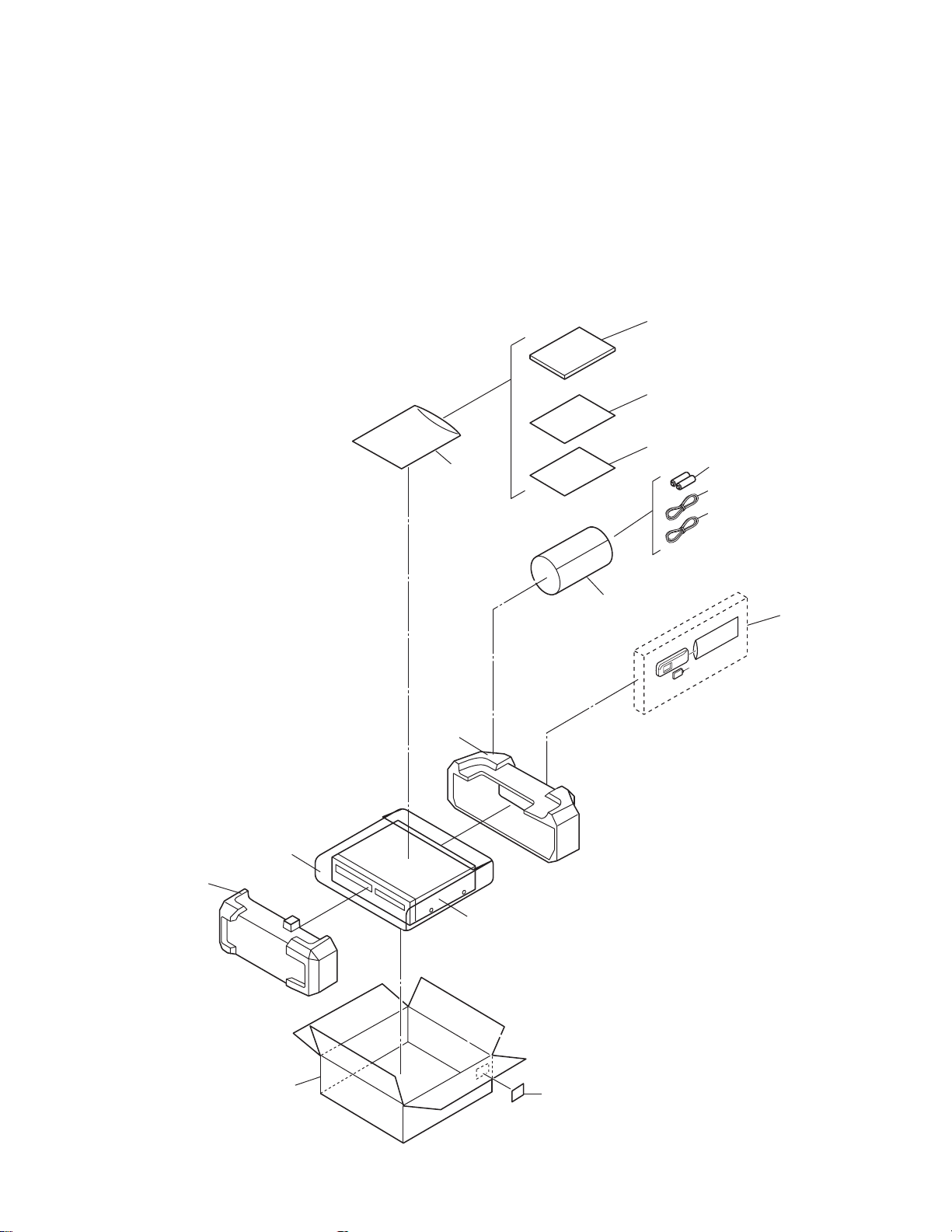
PARTS LIST
SAFETY PRECAUTION
Parts identified by the symbol are critical for safety. Replace only with specified part numbers.
BEWARE OF BOGUS PARTS
Parts that do not meet specifications may cause trouble in regard to safety and performance. We recommend that genuine
JVC parts be used.
1. EXPLODED VIEW
1.1 PACKING AND ACCESSORY ASSEMBLY <M1>
The instruction manual to be provided with this product will differ according to the destination.
310
316
317
311
307
312
313
302
303
302
FINAL ASSY<M2>
308
306
306A
301
SPEC OF BARCODE
(No.YD008)3-1
Page 31

1.2 FINAL ASSEMBLY <M2>
504
504
504
502
504
503
515
MAIN BOARD ASSY<03>
MECHANISM ASSY
<M4>
j
517
511
570
566
510
504
504
503
515
505
515
519
518
518
j
f
e
516
510
i
i
518
520
i
517
i
i
DVD UNIT
TU6001
517
m
<M5>, <M6>
<98>, <99>
565
509
d
c
JS3001
c
i
i
b
562
i
561
560
d
e
f
j
c
FRAME NO.LABEL
561
d
c
j
565
508
b
d
562
561
LP*****
563
d
565
d
564
501
507
3-2(No.YD008)
i
501A
j
501B
j
j
521
a
a
j
521
514
i
a
a
DVD BRACKET BOARD ASSY<90>
Page 32

Make a crease.
back side
CN7103
NOTE) INSERT FFC WIRE TO THE CONNECTOR
AFTER ATTACHING FRONT PANEL.
DRAWING FROM DIRECTION
After Assembling FRONT PANEL
CN7191
%0
from FRONT PANEL
(JACK CN7191)
A/C HEAD
CN3102
CN2001
NOTE) FFC WIRE SHOULD BE POSITIONED BELLOW CASSETTE DOOR.
(FOR AVOID FFC WIRE DISTURB CASSETTE IN AND OUT.)
WR3
WR4
CN503 CN501
back side
CN7301
CN7302
WR5
Make a crease.
CN8301
CN1
right side
DRAWING FROM DIRECTION
CN3102
FIG.4FIG.5
WR2
Z-Z SECTION
JACK BOARD ASSY<36>
CN7191
506
FITTING
BOTTOM SIDE
WR1
506
506
CN7003
506
DISPLAY BOARD ASSY<28>
506
506
506
TOP SIDE
FIG.1
Z
Z
Z
Z
ONLY THIS PORTION IS PUSHED
WHEN ATTACHING DVD UNIT.
(No.YD008)3-3
Page 33

1.3 MECHANISM ASSEMBLY <M4>
112
AA
124
128
126
AA
110
AA
118
77
76
134
AA
122
130
140
74
72
71
AA
73
75
37
17
AA
36
78
121
105
88
BB
90
89
21
4
AA
BB
BB
BB
BB
90
89
38
AA
107
AA
Not used
79
137
151
123
125
126
119
111
120
82
107
80
83
81
105
AA
115
AA
117
56
52
26
58
3
86
AA
55
53
91
1
39
113
112
116
114
A/C HEAD
BOARD ASSY <12>
WR2
57
58
42
50
44
49
WR1
85
PMD0048A-C
Classification Part No. Symbol in drawing
Grease KYODO-SH-JB AA
3-4(No.YD008)
102
AA
69
70
AA
96
94
Oil COSMO-HV56 BB
AA
23B
AA
64
65
23
23A
WR3
67
62
59
AA
68
AA
61
60
63
66
AA
95
93
15
22
AA
24
18
19
20
LOADING MOTOR
BOARD ASSY <55>
16
AA
18B
18A
87
AA
AA
46
47
NOTE:The section marked in AA and BB
indicate lubrication and greasing areas.
Page 34

1.4 DVD TRAVERSE MECHANISM ASSEMBLY <M5>
A
18
29
BEND WIRE AT THE PWB EDGE
AFTER INSERTING WIRE
CN101
29
CN101
CN201
Grease
JVG-31N
CFD-4007ZY2
1401C
28
28
DVD SERVO CONTROL BOARD ASSY <99>
27
A
15
14
12
13
BACK SIDE
17
16
26
3
6
5
3
19
2
25
24
23
4
ETU-DE2-31C
1
LETTER SIDE
11
11
9
8
7
10
22
21
20
63.3mm 0.1mm
(No.YD008)3-5
Page 35

1.5 DVD LOADING MECHANISM ASSEMBLY <M6>
< BACK SIDE >
WIRE ARRANGEMENT
AND SOLDERING.
HOOK WIRES
TO CHASSIS.
-
+
0
2
SWITCH BOARD ASSY <98>
9
8
7
5
PWB
MOLD HOOK
4
1
3
6
2
< BACK SIDE >
DVD SERVO CONTROL BOARD
ASSY <99>
13
13
11
11
13
12
13
14
12
EMU-DE2-31YC
3-6(No.YD008)
DVD TRAVERSE
MECHANISM <M5>
Page 36

2. PARTS LIST
PACKING AND ACCESSORY ASSEMBLY <M1>
Symbol No.
301 LP31263-030A PACKING CASE A
301 LP31263-032A PACKING CASE B
301 LP31263-026A PACKING CASE C
301 LP31263-028A PACKING CASE D,E
302 LP31265-001D CUSHION ASSY
303 LP41038-001A POLY BAG
306 LP21036-038B REMOCON A,C
306 LP21036-039B REMOCON B,D,E
306A LP40254-001B COVER(BATTERY) A,C
306A LP40254-009A COVER(BATTERY) B,D,E
307 ------------ BATTERY R6 TYPE(x2)
308 QPC02202230P POLY BAG 22cm x 22cm
310 LPT0894-001A INST.BOOK (ENGLISH) A
310 LPT0894-002A INST.BOOK (FRENCH) A
310 LPT0895-001A INST.BOOK (ENGLISH) B
310 LPT0895-002A INST.BOOK (FRENCH) B
310 LPT0892-001B INST.BOOK (ENGLISH) C
310 LPT0893-002A INST.BOOK (FRENCH) D
310 LPT0893-001A INST.BOOK (ENGLISH) D,E
311 QPC02503530P POLY BAG 25cm x 35cm
312 QAM0501-003 RF CABLE
313 QAM0498-005 A/V CABLE A,B
316 BT-52006-2 WARRANTY CARD A,B,D
317 BT-51034-1 REGIST CARD C,E
Part No. Part Name Description Local
FINAL ASSEMBLY <M2>
Symbol No.
501 LP10492-013A FRONT PANEL ASSY A
501 LP10492-014A FRONT PANEL ASSY B
501 LP10492-011A FRONT PANEL ASSY C
501 LP10492-012A FRONT PANEL ASSY D,E
501A LP21188-001A CASSETTE DOOR A,C
501A LP21188-002A CASSETTE DOOR B,D,E
501B PQ46448 TORSION SPRING
502 LP10488-004B TOP COVER A,C
502 LP10488-002B TOP COVER B,D,E
503 QYSBSG3006MA TAP SCREW
503 QYSBSG3006NA TAP SCREW
504 QYSBSG3006MA TAP SCREW
504 QYSBSG3006NA TAP SCREW M3 x 6mm(x6) B,D,E
505 PDV2531D DRUM FINAL ASSY
506 QYTDSF2608ZA TAP SCREW
507 LP40990-001A SPECIAL SCREW FRONT PANEL(x2) A,B
507 LP31391-001A SPECIAL SCREW FRONT PANEL(x2) C,D,E
508 LP21190-001A FITTING A,C
508 LP21190-002A FITTING B,D,E
509 LP41077-002A LABEL(CAUTION)
510 QYSPSPD3008ZA SCREW
511 LP10489-001B BOTTOM CHASSIS
514 LP30002-0F1A SPACER
515 LP31391-002A SPECIAL SCREW MECHANISM(x3)
516 LP31391-001A SPECIAL SCREW HOUSING
517 LP31391-001A SPECIAL SCREW MAIN(x3)
518 QYTDSF3008MA TAP SCREW
519 LP21178-016B REAR COVER
520 QYSBSG3006MA TAP SCREW
521 LP31348-001A FOOT (x2)
560 LP21177-001B BRACKET(DVD)
561 LP31391-001A SPECIAL SCREW
562 LP30002-0E5A SPACER (x2)
563 LP31392-001A BRACKET
564 QYSDSF2608ZA TAP SCREW M2.6 x 8mm DVD
565 QYSBSG3010ZA TAP SCREW
566 LP31153-013A STICKER(TOP) A,B
566 LP31153-012A STICKER(TOP) D
566 LP31153-011A STICKER(TOP) C,E
570 LP30002-0B7A SPACER
WR1 QUQ112-2212CG FFC WIRE
WR2 QUQ112-1010CG FFC WIRE
WR3 QUQ210-1916CC FFC WIRE
Part No. Part Name Description Local
M3 x 6mm TOP SIDE(x2)
M3 x 6mm TOP SIDE(x2)
M3 x 6mm TOP REAR(x6)
M2.6 x 8mm FRONT BOAR D ASSY(x9)
M3 x 8mm DRUM(x3)
M3 x 8mm JACK(x4)
M3 x 6mm REAR COVER
BRACKET(DVD)(x3)
M3 x 10mm DVD(x3)
DISPLAY CN7003-MAIN CN3102
JACK CN7191-MAIN CN3103
DVD UNIT CN501-MAIN CN7301
A,C
B,D,E
A,C
Symbol No.
WR4 QUQ210-1716CC FFC WIRE
WR5 QUQ210-0510CC FFC WIRE
Part No. Part Name Description Local
MODEL MARK
HR-XVC22UC
HR-XVC23UC
HR-XVC26US
MODEL MARK
A
HR-XVC27UC
B
HR-XVC27USDE
C
DVD UNIT CN503-MAI N CN7302
DVD UNIT CN1-MAIN CN8301
MECHANISM ASSEMBLY <M4>
Symbol No.
1 LP21039-001X MAIN DECK ASSY A,D
1 LP21039-001Y MAIN DECK ASSY B,C,E
3 LP40097-002E GUIDE POLE CAP
4 NAH0004-001 FE HEAD
15 LP30958-001B LOADING GEAR BASE
16 QYTPST2620ZA TAP SCREW M2.6 x 20mm(x2)
17 QYTDST2606ZA SCREW M2.6 x 6mm
18 LP40798-001A
18A LP21040-001A
18B LP40799-001A
19 LP40837-001A
20 LP40903-002B FIXING PLATE
21 LP40806-001D
22 LP30959-001B LOADING GEAR
23 LP40802-001C
23A LP21041-001D
23B LP40803-001A
24 LP40838-001A
26 LP40808-001E
36 LP21055-001G TAKE UP LEVER
37 LP40943-001A TENSION SPRING
38 LP40859-001D TAKE UP HEAD
39 LP30961-001C LID GUIDE
42 LP40810-001C
44 LP40840-001D TORSION SPRING
46 LP30963-001C PRESS LEVER
47 PQM30017-24 SLIT WASHER
49 LP40813-001D GUIDE ARM ASSY
50 LP40841-001A TORSION SPRING
52 NAH0005-001 AC HEAD
53 LP30965-001A HEAD BASE
55 LP40842-001D
56 QYTDST2006MA TAP SCREW M2 x 6mm
57 LP41036-002A A/C ADJ.SCREW (x2)
58 QYTDST2606ZA TAP SCREW M2.6 x 6mm(x2)
59 QAR0289-001 LOADING MOTOR
60 QYTPSP3003ZA SCREW M3 x 3mm(x2)
61 LP21056-002J MOTOR BRACKET
62 QYTPST2620ZA TAP SCREW M2.6 x 20mm
63 LP40814-001B WORM BEARING
64 LP21044-001E CONTROL CAM
65 PQM30017-24 SLIT WASHER
66 LP40815-001A WORM GEAR
67 LP40816-001B HELICAL GEAR
68 LP40817-001A CONNECT GEAR
69 LP10400-001N CONTROL PLATE
70 LP40843-001A TORSION SPRING
71 LP40818-001B TENSION ARM ASSY
72 LP40844-001F TENSION SPRING
73 LP21045-001E TENSION ARM BASE
74 LP40821-001A TENSION BAND ASSY
75 LP30967-001B BAND HOLDER-1
76 LP30968-001C BAND HOLDER-2
77 LP40822-002B ADJUST PIN
78 LP31000-005E TENSION ARM LEVER
79 LP21046-001C MAIN BRAKE(TAKE UP)
80 LP40824-001A BAND BRAKE ASSY
81 LP30969-002B BRAKE LEVER
82 LP30003-033B TENSION SPRING
83 LP30003-035B TENSION SPRING
85 QAR0322-001 CAPSTAN MOTOR
86 QYTPSG2606ZA TAP SCREW M2.6 x 6mm(x3)
87 LP30005-010A BELT CAPSTAN MOTOR
88 LP30970-001A IDLER ARM
89 LP40828-004A IDLER GEAR 1 (x2)
90 LP40829-002A IDLER GEAR 2 (x2)
91 LP31014-002A WIRE HOLDER
Part No. Part Name Description Local
LOADING GEAR(SUPPLY) ASSY
LOADING GEAR(SUPPLY)
LOADING ARM(SUPPLY) ASSY
TORSION SPRING(SUPPLY)
POLE BASE ASSY(SUPPLY)
LOADING GEAR(TAKE UP) ASSY
LOADING GEAR(TAKE UP)
LOADING ARM(TAKE UP) ASSY
TORSION SPRING(TAKE UP)
POLE BASE ASSY(TAKE UP)
PINCH ROLLER ARM ASSY
COMPRESSION SPRING
(No.YD008)3-7
Page 37

Symbol No.
93 LP40934-001B CLUTCH UNIT
94 PQM30017-47 SLIT WASHER
95 LP30973-001A DIRECT GEAR
96 LP40939-001A
102 LP30974-001C CHANGE LEVER
105 LP21049-001A REEL DISK (x2)
107 LP30017-004A SPACER REEL DISK(x2)
110 LP10401-001L SIDE FRAME(L)
111 LP10402-001M SIDE FRAME(R)
112 QYTDST2606ZA TAP SCREW M2.6 x 6mm(x2)
113 LP40917-001D TORSION SPRING
114 LP30976-001F SIDE PLATE
115 LP30977-002D LIMIT PLATE
116 LP40846-001C LIMIT SPRING
117 LP31100-002A DRIVE LEVER
118 LP30978-001B DRIVE ARM(L)
119 LP30979-001S DRIVE ARM(R)
120 LP40847-001B TORSION SPRING
121 LP30980-001F CONNECT PLATE
122 LP10403-001C SIDE HOLDER(L)
123 LP10404-001E SIDE HOLDER(R)
124 LP30983-001B LOCK LEVER(L)
125 LP30984-001B LOCK LEVER(R)
126 LP40924-001D TENSION SPRING (x2)
128 LP40857-001B EARTH SPRING(2)
130 LP30981-001G
134 LP21051-002C REC SAFETY LEVER
137 LP21052-001K TOP FRAME
140 LP41153-001A EARTH SPRING(3)
151 LP30985-002M DOOR OPENER
WR1 WJT0117-001A E-CARD WIRE
WR2 WJT0067-001B E-CARD WIRE A/C HEAD CN2001
WR3 WJS0022-001A E-FL/RB WIRE LOADING MOTOR
Part No. Part Name Description Local
COMPRESSION SPRING
CASSETTE HOLDER ASSY
DVD TRAVERSE MECHANISM ASSEMBLY <M5>
Symbol No.
1 LE20727-001A MECHA BASE
2 LE20699-002A SPINDLE BASE
3 QYSDST2605M TAP SCREW M2.6 x 5mm(x2)
4 LE40931-001A SHAFT
5 LV33991-001A ADJUST SPRING
6 QYSPSFU2040M TAP SCREW M2 x 4mm
7 LE20698-004A FEED HOLDER
8 QAR0215-001 FEED MOTOR
9 LV41510-001A FEED GEAR T
10 QYSPSPU2040M SCREW M2 x 4mm(x2)
11 QYSDST2605M TAP SCREW M2.6 x 5mm(x2)
12 QAL0507-001 PICK UP
13 LE20700-001A SW ACTUATOR
14 LE31067-002A LEAD SPRING
15 QYSPSFU1740Z TAP SCREW M1.7 x 4mm(x2)
16 LE40929-001A SW.LEVER
17 QYSPSFU1740Z TAP SCREW M1.7 x 4mm
18 QUQ105-2411AC FFC
19 LE40931-001A SHAFT
20 LE40855-001A FEED GEAR E
21 LE40918-001A LEAD SCREW
22 LE40930-001A FEED GEAR M
23 LE40928-001A THURUST SPRING
24 LE40927-001A PLATE
25 QYSDST2614Z TAPPING SCREW M2.6 x 14mm
26 QAR0316-001 SPINDLE MOTOR
27 QYSPSPU1740Z SCREW M1.7 x 4mm(x3)
28 LE40858-002A SPECIAL SCREW (x3)
29 QYSDST2004Z SCREW 2mm x 4mm(x2)
3-8(No.YD008)
Part No. Part Name Description Local
*The VCR goes to jig RCU mode after replacing the EEPROM and the VCR does not accept some RCU command.
Therefore please set the VCR to the user RCU mode after replacing the EEPROM.
The method of setting the VCR to the user RCU mode is written on the service manual.
MODEL MARK
HR-XVC22UC
HR-XVC23UC
HR-XVC26US
MODEL MARK
A
HR-XVC27UC
B
HR-XVC27USDE
C
DVD LOADING MECHANISM ASSEMBLY <M6>
Symbol No.
1 LE10283-012A LOADER SUB ASSY
2 QAR0197-001 MOTOR MABUCHI
3 LV42087-002A MOTOR PULLEY
4 QYSPSPU1730Z SCREW FOR MOTOR(x2)
5 LE40897-001A BELT
6 LE31046-003A CLAMPER
7 LV42930-003A P.C.MAGNET
8 LE40899-001A YOKE
9 LE40906-001A SPECIAL SCREW
11 LE40900-003A INSULATOR (x2)
12 LE40900-005A INSULATOR (x2)
13 LE40901-001A SPECIAL SCREW (x4)
14 QYWFM419025 WASHER
Part No. Part Name Description Local
1.9mm/21.4mm x 0.02mm
MAIN BOARD ASSEMBLY <03>
Symbol No.
PW1 LPA10227-02C MAIN BOARD ASSY A,B
PW1 LPA10227-01C MAIN BOARD ASSY C,D,E
IC1 JCP8060-NVA IC
IC2201 AN3663FBP IC
IC3001 HD6432199RB04F IC(MCU) MASK
IC3002 IC-PST3427U-X IC
IC3003 LPN0864-002B-01 IC(EEPROM)
IC3003 LPN0864-001B-02 IC(EEPROM)
IC5201 UTCTL431-T IC
IC5201 or MM1431AT-T IC
IC5201 or L5431-T IC
IC5201 or TL431/A/-T IC
IC5301 UTCTL431-T IC
IC5302 MM1565AF-X IC
IC7102 MM1507XN-X IC
IC7104 MM1623XF-X IC
IC7501 74VHCT08ASJ-X IC
IC8001 HA17558AF-X IC
IC8001 or RC4558D-X IC
IC8201 MN101C30AJE IC(MCU)
IC8201 or MN101CP30AJE IC(MCU)
IC8202 SN74HCT08APW-X IC
IC8301 LB1641 IC
Q202 2SD601A/QRS/-X TRANSISTOR
Q202 or 2SC2412K/QRS/-X TRANSISTOR
Q202 or 2SC3928A/QRS/-X TRANSISTOR
Q2001 2SD601A/QRS/-X TRANSISTOR
Q2001 or 2SC2412K/QRS/-X TRANSISTOR
Q2001 or 2SC3928A/QRS/-X TRANSISTOR
Q2002 2SD601A/QRS/-X TRANSISTOR
Q2002 or 2SC2412K/QRS/-X TRANSISTOR
Q2002 or 2SC3928A/QRS/-X TRANSISTOR
Q2003 UN211E-X DIGI TRANSISTOR
Q2003 or DTA144WKA-X TRANSISTOR
Q2003 or RT1P44HC-X DIGI TRANSISTOR
Q2051 2SD601A/QRS/-X TRANSISTOR
Q2051 or 2SC2412K/QRS/-X TRANSISTOR
Q2051 or 2SC3928A/QRS/-X TRANSISTOR
Q2052 2SB709A/QR/-X TRANSISTOR
Q2052 or 2SA1037AK/QR/-X TRANSISTOR
Q2052 or 2SA1530A/QR/-X SI TRANSISTOR
Q2053 UN221E-X TRANSTSTOR
Q2053 or DTC144WKA-X DIGI TRANSISTOR
Q2053 or RT1N44HC-X DIGI TRANSISTOR
Q2054 2SB709A/QR/-X TRANSISTOR
Q2054 or 2SA1037AK/QR/-X TRANSISTOR
Q2054 or 2SA1530A/QR/-X SI TRANSISTOR
Q2055 UN221E-X TRANSTSTOR
Q2055 or DTC144WKA-X DIGI TRANSISTOR
Q2055 or RT1N44HC-X DIGI TRANSISTOR
Q2201 UN211E-X DIGI TRANSISTOR
Q2201 or DTA144WKA-X TRANSISTOR
Part No. Part Name Description Local
*(REFER TO BELOW)
*(REFER TO BELOW)
A,B
C,D,E
Page 38

Symbol No.
Part No. Part Name Description Local
Symbol No.
MODEL MARK
HR-XVC22UC
HR-XVC23UC
HR-XVC26US
MODEL MARK
A
HR-XVC27UC
B
HR-XVC27USDE
C
Part No. Part Name Description Local
Q2201 or RT1P44HC-X DIGI TRANSISTOR
Q2202 UN221E-X TRANSTSTOR
Q2202 or DTC144WKA-X DIGI TRANSISTOR
Q2202 or RT1N44HC-X DIGI TRANSISTOR
Q2203 2SD601A/QRS/-X TRANSISTOR
Q2203 or 2SC2412K/QRS/-X TRANSISTOR
Q2203 or 2SC3928A/QRS/-X TRANSISTOR
Q2204 2SD601A/QRS/-X TRANSISTOR
Q2204 or 2SC2412K/QRS/-X TRANSISTOR
Q2204 or 2SC3928A/QRS/-X TRANSISTOR
Q3002 PTZ-NV16A IC(PHOTO SENSOR)
Q3004 2SD601A/QRS/-X TRANSISTOR
Q3004 or 2SC2412K/QRS/-X TRANSISTOR
Q3004 or 2SC3928A/QRS/-X TRANSISTOR
Q3005 2SD601A/QRS/-X TRANSISTOR
Q3005 or 2SC2412K/QRS/-X TRANSISTOR
Q3005 or 2SC3928A/QRS/-X TRANSISTOR
Q4001 UN2211-X TRANSISTOR
Q4001 or DTC114EKA-X TRANSISTOR
Q4001 or RT1N141C-X DIGI TRANSISTOR
Q5101 2SK2043-CB14 FET
Q5102 2SC3576-JVC-T TRANSISTOR
Q5103 2SB709A/QR/-X TRANSISTOR
Q5103 or 2SA1037AK/QR/-X TRANSISTOR
Q5103 or 2SA1530A/QR/-X SI TRANSISTOR
Q5306 2SD2144S/UV/-T TRANSISTOR
Q5307 UN211E-X DIGI TRANSISTOR
Q5307 or DTA144WKA-X TRANSISTOR
Q5307 or RT1P44HC-X DIGI TRANSISTOR
Q5309 UN2211-X TRANSISTOR
Q5309 or DTC114EKA-X TRANSISTOR
Q5309 or RT1N141C-X DIGI TRANSISTOR
Q5310 2SD1858/QR/-T TRANSISTOR
Q5311 2SC5739/QP/ TRANSISTOR
Q5315 2SD1858/QR/-T TRANSISTOR
Q6030 2SB709A/QR/-X TRANSISTOR
Q6030 or 2SA1037AK/QR/-X TRANSISTOR
Q6030 or 2SA1530A/QR/-X SI TRANSISTOR
Q7113 2SA1037AK/QR/-X TRANSISTOR
Q7113 or 2SB709A/QR/-X TRANSISTOR
Q7113 or 2SA1530A/QR/-X SI TRANSISTOR
Q8001 2SD601A/QRS/-X TRANSISTOR
Q8001 or 2SC2412K/QRS/-X TRANSISTOR
Q8001 or 2SC3928A/QRS/-X TRANSISTOR
Q8002 2SD601A/QRS/-X TRANSISTOR
Q8002 or 2SC2412K/QRS/-X TRANSISTOR
Q8002 or 2SC3928A/QRS/-X TRANSISTOR
Q8052 2SD601A/QRS/-X TRANSISTOR
Q8052 or 2SC2412K/QRS/-X TRANSISTOR
Q8052 or 2SC3928A/QRS/-X TRANSISTOR
Q8053 UN2111-X TRANSISTOR
Q8053 or DTA114EKA-X DIGI TRANSISTOR
Q8053 or RT1P141C-X DIGI TRANSISTOR
D201 1SS133-T2 DIODE
D2001 1SS133-T2 DIODE
D2001 or 1SS270A-T2 SI DIODE
D2251 1SS133-T2 DIODE
D2251 or 1SS270A-T2 SI DIODE
D3001 LNB2301L01VI LED
D3002 1SS133-T2 DIODE
D3002 or 1SS270A-T2 SI DIODE
D3003 RD33ES/B3/-T2 Z DIODE
D3003 or MTZJ33C-T2 Z DIODE
D3004 10EDB20-T2 SI DIODE
D3004 or 1A3G-T2 SI DIODE
D3005 10EDB20-T2 SI DIODE
D3005 or 1A3G-T2 SI DIODE
D4002 1SS133-T2 DIODE
D5001 S1WB/A/60-4102 BRIDGE DIODE
D5001 or S1WB/A/60-X BRIDGE DIODE
D5101 10EDB20-T2 SI DIODE
D5101 or 1A3G-T2 SI DIODE
D5102 10ERB40-T2 FR DIODE
D5102 or AU01-T2 SI DIODE
D5103 1SS133-T2 DIODE
D5103 or 1SS270A-T2 SI DIODE
D5105 1SS133-T2 DIODE
D5105 or 1SS270A-T2 SI DIODE
D5106 MTZJ33D-T2 Z DIODE
D5106 or RD33ES/B4/-T2 Z DIODE
D5208 1S4-T2 SB DIODE
D5208 or AW04-T2 SB DIODE
D5208 or SBO40-T2 SB DIODE
D5209 PG104RS-T2 FR DIODE
D5209 or 10ERB20-T2 FR DIODE
D5209 or 1F4G-T2 FR DIODE
D5209 or AU01Z-T2 FR DIODE
D5209 or 1SR153-400-T2 FR DIODE
D5212 SB240-F26 SB DIODE
D5212 or RK14LF-B2 SBD
D5212 or 21DQ04-F SBD
D5213 1F4G-T2 FR DIODE
D5213 or 10ERB20-T2 FR DIODE
D5301 MTZJ15C-T2 Z DIODE
D5301 or RD15ES/B3/-T2 Z DIODE
D5305 MTZJ11C-T2 Z DIODE
D5305 or RD11ES/B3/-T2 Z DIODE
D5306 MTZJ5.6C-T2 Z DIODE
D5306 or RD5.6ES/B3/-T2 Z DIODE
D5310 MTZJ10B-T2 Z DIODE
D5310 or RD10ES/B2/-T2 Z DIODE
D6002 HZ30-2L-T2 Z DIODE
D6002 or HZ30-2LTD Z DIODE
D8001 1SS133-T2 DIODE
D8001 or 1SS270A-T2 SI DIODE
D8301 RD5.1ES/B2/-T2 Z DIODE
D8301 or MTZJ5.1B-T2 Z DIODE
PC3001 RPI-304J IC(PHOTO SENSOR)
PC3002 RPI-304J IC(PHOTO SENSOR)
PC5101 PC123Y22FZ PHOTO COUPLER
C1 NDC31HJ-151X C CAPACITOR 150pF 50V J
C2 NDC31HJ-330X C CAPACITOR 33pF 50V J
C4 QEKJ1EM-106Z E CAPACITOR 10uF 25V M
C5 NCB31CK-104X C CAPACITOR 0.1uF 16V K
C6 NCB31CK-104X C CAPACITOR 0.1uF 16V K
C7 NCB31CK-104X C CAPACITOR 0.1uF 16V K
C8 NCF31AZ-105X C CAPACITOR 1uF 10V Z
C9 QEKJ1HM-225Z E CAPACITOR 2.2uF 50V M
C11 NCF31AZ-105X C CAPACITOR 1uF 10V Z
C12 NCF31AZ-105X C CAPACITOR 1uF 10V Z
C14 NCF31AZ-105X C CAPACITOR 1uF 10V Z
C15 NCB31CK-104X C CAPACITOR 0.1uF 16V K
C17 NCF31EZ-104X C CAPACITOR 0.1uF 25V Z
C19 NCB31CK-104X C CAPACITOR 0.1uF 16V K
C20 NCB31CK-104X C CAPACITOR 0.1uF 16V K
C22 NCF31EZ-104X C CAPACITOR 0.1uF 25V Z
C24 NCF31EZ-104X C CAPACITOR 0.1uF 25V Z
C25 QEKJ1HM-335Z E CAPACITOR 3.3uF 50V M
C26 QEKJ1EM-106Z E CAPACITOR 10uF 25V M
C27 NCB31EK-103X C CAPACITOR 0.01uF 25V K
C30 NCB31HK-331X C CAPACITOR 330pF 50V K
C31 QEKJ0JM-476Z E CAPACITOR 47uF 6.3V M
C33 QEKJ1EM-106Z E CAPACITOR 10uF 25V M
C34 NCB31EK-103X C CAPACITOR 0.01uF 25V K
C35 NCB31EK-103X C CAPACITOR 0.01uF 25V K
C36 QEKJ1HM-105Z E CAPACITOR 1uF 50V M
C37 NDC31HJ-4R0X C CAPACITOR 4pF 50V J
C40 NCF31EZ-104X C CAPACITOR 0.1uF 25V Z
C41 NCB31CK-104X C CAPACITOR 0.1uF 16V K
C43 QEKJ1HM-335Z E CAPACITOR 3.3uF 50V M
C44 QEKJ1HM-225Z E CAPACITOR 2.2uF 50V M
C45 NCB31EK-472X C CAPACITOR 4700pF 25V K
C46 NCB31CK-333X C CAPACITOR 0.033uF 16V K
C47 QEKJ1HM-474Z E CAPACITOR 0.47uF 50V M
C48 NCB31EK-223X C CAPACITOR 0.022uF 25V K
C49 QEKJ1HM-475Z E CAPACITOR 4.7uF 50V M
C56 NCB31CK-104X C CAPACITOR 0.1uF 16V K
C57 NCF31EZ-104X C CAPACITOR 0.1uF 25V Z
C58 NCF31EZ-104X C CAPACITOR 0.1uF 25V Z
C59 NCF31EZ-104X C CAPACITOR 0.1uF 25V Z
C60 NCF31EZ-104X C CAPACITOR 0.1uF 25V Z
C77 NCF31EZ-104X C CAPACITOR 0.1uF 25V Z
C78 NCF31EZ-104X C CAPACITOR 0.1uF 25V Z
(No.YD008)3-9
Page 39

Symbol No.
Part No. Part Name Description Local
Symbol No.
MODEL MARK
HR-XVC22UC
HR-XVC23UC
HR-XVC26US
MODEL MARK
A
HR-XVC27UC
B
HR-XVC27USDE
C
Part No. Part Name Description Local
C201 NDC31HJ-220X C CAPACITOR 22pF 50V J
C202 QEKJ1HM-475Z E CAPACITOR 4.7uF 50V M
C203 NCB31HK-102X C CAPACITOR 1000pF 50V K
C204 NCB31HK-681X C CAPACITOR 680pF 50V K
C205 QEKJ1HM-475Z E CAPACITOR 4.7uF 50V M
C206 NCB31HK-681X C CAPACITOR 680pF 50V K
C207 QEKJ1HM-475Z E CAPACITOR 4.7uF 50V M
C209 QEKJ0JM-476Z E CAPACITOR 47uF 6.3V M
C210 NCB31EK-103X C CAPACITOR 0.01uF 25V K
C212 NCF31EZ-104X C CAPACITOR 0.1uF 25V Z
C213 NCF31EZ-104X C CAPACITOR 0.1uF 25V Z
C2001 QEKJ1HM-475Z E CAPACITOR 4.7uF 50V M
C2002 QEKJ1HM-105Z E CAPACITOR 1uF 50V M
C2005 QEKJ1HM-475Z E CAPACITOR 4.7uF 50V M
C2006 NCB31EK-682X C CAPACITOR 6800pF 25V K
C2007 QEKJ1CM-226Z E CAPACITOR 22uF 16V M
C2008 QEKJ1HM-475Z E CAPACITOR 4.7uF 50V M
C2009 NCB31HK-102X C CAPACITOR 1000pF 50V K
C2010 NCB31HK-681X C CAPACITOR 680pF 50V K
C2011 QEKJ1HM-475Z E CAPACITOR 4.7uF 50V M
C2012 QEKJ1HM-475Z E CAPACITOR 4.7uF 50V M
C2051 NCB31HK-331X C CAPACITOR 330pF 50V K
C2052 QFV61HJ-823Z MF CAPACITOR 0.082uF 50V J
C2053 NCB31HK-472X C CAPACITOR 4700pF 50V K
C2054 NCB31EK-223X C CAPACITOR 0.022uF 25V K
C2055 QEKJ1EM-106Z E CAPACITOR 10uF 25V M
C2201 QEKJ1EM-106Z E CAPACITOR 10uF 25V M
C2202 QEKJ1HM-475Z E CAPACITOR 4.7uF 50V M
C2203 QEKJ1HM-475Z E CAPACITOR 4.7uF 50V M
C2204 QEKJ0JM-336Z E CAPACITOR 33uF 6.3V M
C2205 QEKJ1EM-106Z E CAPACITOR 10uF 25V M
C2206 QEKJ1EM-106Z E CAPACITOR 10uF 25V M
C2207 NCB31EK-153X C CAPACITOR 0.015uF 25V K
C2208 NCB31EK-153X C CAPACITOR 0.015uF 25V K
C2209 QEKJ1EM-106Z E CAPACITOR 10uF 25V M
C2210 QEKJ1EM-106Z E CAPACITOR 10uF 25V M
C2211 QEKJ0JM-336Z E CAPACITOR 33uF 6.3V M
C2212 QEKJ0JM-476Z E CAPACITOR 47uF 6.3V M
C2214 QEKJ1EM-106Z E CAPACITOR 10uF 25V M
C2215 QEKJ1EM-106Z E CAPACITOR 10uF 25V M
C2218 QEKJ1EM-106Z E CAPACITOR 10uF 25V M C,D,E
C2219 QEKJ1CM-226Z E CAPACITOR 22uF 16V M C,D,E
C2220 QEKJ1EM-106Z E CAPACITOR 10uF 25V M
C2221 NCB31EK-223X C CAPACITOR 0.022uF 25V K
C2222 NCF31EZ-104X C CAPACITOR 0.1uF 25V Z
C2234 NCB30JK-105X C CAPACITOR 1uF 6.3V K
C2235 NCB30JK-105X C CAPACITOR 1uF 6.3V K
C2251 NCB31EK-103X C CAPACITOR 0.01uF 25V K
C2252 NCB31EK-103X C CAPACITOR 0.01uF 25V K
C2253 NCB31EK-103X C CAPACITOR 0.01uF 25V K
C2254 QEKJ0JM-476Z E CAPACITOR 47uF 6.3V M
C2255 NCF31EZ-104X C CAPACITOR 0.1uF 25V Z
C2256 NCB31EK-103X C CAPACITOR 0.01uF 25V K
C2257 NCB31EK-103X C CAPACITOR 0.01uF 25V K
C2259 QEKJ1HM-334Z E CAPACITOR 0.33uF 50V M
C3011 QETN1AM-477Z E CAPACITOR 470uF 10V M
C3012 QEKJ0JM-476Z E CAPACITOR 47uF 6.3V M
C3014 QEKJ0JM-476Z E CAPACITOR 47uF 6.3V M
C3016 NCF31EZ-104X C CAPACITOR 0.1uF 25V Z
C3022 NCF31EZ-104X C CAPACITOR 0.1uF 25V Z
C3024 NDC31HJ-120X C CAPACITOR 12pF 50V J
C3030 QEKJ0JM-476Z E CAPACITOR 47uF 6.3V M
C3031 NCF31EZ-104X C CAPACITOR 0.1uF 25V Z
C3033 NCF31EZ-104X C CAPACITOR 0.1uF 25V Z
C3036 NDC31HJ-180X C CAPACITOR 18pF 50V J
C3037 NDC31HJ-120X C CAPACITOR 12pF 50V J
C3041 NDC31HJ-180X C CAPACITOR 18pF 50V J
C3045 NCB31EK-103X C CAPACITOR 0.01uF 25V K
C3050 NCF31EZ-104X C CAPACITOR 0.1uF 25V Z
C3052 QEKJ1EM-106Z E CAPACITOR 10uF 25V M
C3054 NCB31HK-222X C CAPACITOR 2200pF 50V K
C3071 QETJ1HM-336Z E CAPACITOR 33uF 50V M
C4002 NCF31EZ-104X C CAPACITOR 0.1uF 25V Z
C4004 QEKJ1CM-226Z E CAPACITOR 22uF 16V M
C4005 NDC31HJ-181X C CAPACITOR 180pF 50V J
C4006 QEKJ0JM-476Z E CAPACITOR 47uF 6.3V M
C4008 QEQF1HM-105Z E CAPACITOR 1uF 50V M
C4009 NRSA63J-0R0X MG RESISTOR 0Ω 1/16W J
C4010 NCB31EK-223X C CAPACITOR 0.022uF 25V K
C4011 NCB31CK-104X C CAPACITOR 0.1uF 16V K
C4012 QEKJ1HM-224Z E CAPACITOR 0.22uF 50V M
C4014 NDC31HJ-101X C CAPACITOR 100pF 50V J
C4015 NCB31HK-221X C CAPACITOR 220pF 50V K
C5001 QFZ9077-473 MPP CAPACITOR 0.047uF 275V M
C5003 QCZ9079-101 C CAPACITOR 100pF AC250V K
C5004 QCZ9079-472 C CAPACITOR 4700pF AC250V M
C5006 QETM2DM-157 E CAPACITOR 150uF 200V M
C5101 QCZ0336-330Z C CAPACITOR 33pF 1kV J
C5102 QCZ0333-472 C CAPACITOR 4700pF 1kV K
C5104 QETN1HM-105Z E CAPACITOR 1uF 50V M
C5106 NCB31HK-821X C CAPACITOR 820pF 50V K
C5108 NCB31HK-104X C CAPACITOR 0.1uF 50V K
C5109 NCB31HK-183X C CAPACITOR 0.018uF 50V K
C5202 QEMT1AM-128 E CAPACITOR 1200uF 10V M
C5204 QEMT1AM-128 E CAPACITOR 1200uF 10V M
C5205 QEMU1CM-397Z E CAPACITOR 390uF 16V M
C5207 QETN2AM-475Z E CAPACITOR 4.7uF 100V M
C5209 QETN1AM-107Z E CAPACITOR 100uF 10V M
C5210 QETN1CM-107Z E CAPACITOR 100uF 16V M
C5211 QETN1AM-107Z E CAPACITOR 100uF 10V M
C5214 NCB31AK-154X C CAPACITOR 0.15uF 10V K
C5303 QETN1HM-225Z E CAPACITOR 2.2uF 50V M
C5304 QETN1CM-107Z E CAPACITOR 100uF 16V M
C5305 QETN1AM-107Z E CAPACITOR 100uF 10V M
C5306 NCF31AZ-105X C CAPACITOR 1uF 10V Z
C5307 NCB31HK-471X C CAPACITOR 470pF 50V K
C5309 QETN1AM-107Z E CAPACITOR 100uF 10V M
C5310 QETN1AM-107Z E CAPACITOR 100uF 10V M
C5314 QETN1CM-107Z E CAPACITOR 100uF 16V M
C6013 NCB31HK-102X C CAPACITOR 1000pF 50V K
C6021 NCB31HK-331X C CAPACITOR 330pF 50V K C,D,E
C6053 NDC31HJ-120X C CAPACITOR 12pF 50V J C,D,E
C6054 NDC31HJ-100X C CAPACITOR 10pF 50V J C,D,E
C6501 NCB31CK-104X C CAPACITOR 0.1uF 16V K
C6502 QEKJ1EM-106Z E CAPACITOR 10uF 25V M
C6503 QEKJ1HM-105Z E CAPACITOR 1uF 50V M
C6504 NCF31EZ-104X C CAPACITOR 0.1uF 25V Z
C6505 QEKJ1HM-335Z E CAPACITOR 3.3uF 50V M
C6508 NCB31EK-223X C CAPACITOR 0.022uF 25V K
C6509 NCB31CK-104X C CAPACITOR 0.1uF 16V K
C6511 NCF31EZ-104X C CAPACITOR 0.1uF 25V Z
C6512 NCB31EK-223X C CAPACITOR 0.022uF 25V K
C6513 QEKJ1HM-225Z E CAPACITOR 2.2uF 50V M
C6514 NCB31EK-223X C CAPACITOR 0.022uF 25V K
C6515 QEKJ1HM-335Z E CAPACITOR 3.3uF 50V M
C6516 QEKJ1EM-475Z E CAPACITOR 4.7uF 25V M
C6517 NCB31AK-224X C CAPACITOR 0.22uF 10V K
C6532 NCF31EZ-104X C CAPACITOR 0.1uF 25V Z
C7114 QETJ0JM-477Z E CAPACITOR 470uF 6.3V M
C7117 QEKJ1EM-106Z E CAPACITOR 10uF 25V M
C7118 QEKJ1EM-106Z E CAPACITOR 10uF 25V M
C7119 NCF31EZ-104X C CAPACITOR 0.1uF 25V Z
C7120 QETJ0JM-477Z E CAPACITOR 470uF 6.3V M
C7121 NCB31EK-103X C CAPACITOR 0.01uF 25V K
C7123 QETJ0JM-477Z E CAPACITOR 470uF 6.3V M
C7124 QETJ0JM-477Z E CAPACITOR 470uF 6.3V M
C7125 QETJ0JM-477Z E CAPACITOR 470uF 6.3V M
C7129 NCF31EZ-104X C CAPACITOR 0.1uF 25V Z
C7131 NCB31EK-103X C CAPACITOR 0.01uF 25V K
C7132 NCF31EZ-104X C CAPACITOR 0.1uF 25V Z
C7133 QEKJ1CM-226Z E CAPACITOR 22uF 16V M
C7134 NCF31EZ-104X C CAPACITOR 0.1uF 25V Z
C7135 NCF31AZ-105X C CAPACITOR 1uF 10V Z
C7136 NCF31AZ-105X C CAPACITOR 1uF 10V Z
C7502 NCF31EZ-104X C CAPACITOR 0.1uF 25V Z
C7503 QEKJ1HM-475Z E CAPACITOR 4.7uF 50V M
C7504 NDC31HJ-151X C CAPACITOR 150pF 50V J
C8001 QEKJ1CM-226Z E CAPACITOR 22uF 16V M
C8002 QEKJ1CM-226Z E CAPACITOR 22uF 16V M
C8003 NCB31HK-821X C CAPACITOR 820pF 50V K
C8004 NCB31HK-821X C CAPACITOR 820pF 50V K
C8005 NCB31HK-821X C CAPACITOR 820pF 50V K
C8006 NCB31HK-821X C CAPACITOR 820pF 50V K
C8007 QEKJ1CM-226Z E CAPACITOR 22uF 16V M
C8008 QEKJ1CM-226Z E CAPACITOR 22uF 16V M
C8052 QEKJ0JM-107Z E CAPACITOR 100uF 6.3V M
3-10(No.YD008)
Page 40

Symbol No.
Part No. Part Name Description Local
Symbol No.
MODEL MARK
HR-XVC22UC
HR-XVC23UC
HR-XVC26US
MODEL MARK
A
HR-XVC27UC
B
HR-XVC27USDE
C
Part No. Part Name Description Local
C8201 QEKJ0JM-476Z E CAPACITOR 47uF 6.3V M
C8202 NCF31EZ-104X C CAPACITOR 0.1uF 25V Z
C8203 NCF31EZ-104X C CAPACITOR 0.1uF 25V Z
C8301 QETN1CM-107Z E CAPACITOR 100uF 16V M
C8302 NCB31EK-103X C CAPACITOR 0.01uF 25V K
C8303 NCF31EZ-104X C CAPACITOR 0.1uF 25V Z
R1 NRSA63J-622X MG RESISTOR 6.2kΩ 1/16W J
R2 NRSA63J-152X MG RESISTOR 1.5kΩ 1/16W J
R3 NRSA63J-822X MG RESISTOR 8.2kΩ 1/16W J
R11 NRSA63J-472X MG RESISTOR 4.7kΩ 1/16W J
R12 NRSA63J-102X MG RESISTOR 1kΩ 1/16W J
R36 NRSA63J-472X MG RESISTOR 4.7kΩ 1/16W J
R37 NRSA63J-103X MG RESISTOR 10kΩ 1/16W J
R201 NRSA63J-471X MG RESISTOR 470Ω 1/16W J
R202 NRSA63J-103X MG RESISTOR 10kΩ 1/16W J
R203 NRSA63J-103X MG RESISTOR 10kΩ 1/16W J
R204 NRSA63J-474X MG RESISTOR 470kΩ 1/16W J
R205 NRSA63J-301X MG RESISTOR 300Ω 1/16W J
R206 NRSA63J-474X MG RESISTOR 470kΩ 1/16W J
Ω
R210 NRSA63J-0R0X MG RESISTOR 0
R212 NRSA63J-471X MG RESISTOR 470
1/16W J
Ω
1/16W J
R2007 NRSA63J-123X MG RESISTOR 12kΩ 1/16W J
R2010 NRSA63J-123X MG RESISTOR 12kΩ 1/16W J
R2013 NRSA63J-123X MG RESISTOR 12kΩ 1/16W J
R2014 NRSA63J-394X MG RESISTOR 390kΩ 1/16W J
R2015 NRSA63J-271X MG RESISTOR 270Ω 1/16W J
R2016 NRSA63J-333X MG RESISTOR 33kΩ 1/16W J
R2017 NRSA63J-223X MG RESISTOR 22kΩ 1/16W J
R2018 NRSA63J-472X MG RESISTOR 4.7kΩ 1/16W J
R2019 NRSA63J-472X MG RESISTOR 4.7kΩ 1/16W J
R2021 NRSA63J-333X MG RESISTOR 33kΩ 1/16W J
R2022 NRSA63J-103X MG RESISTOR 10kΩ 1/16W J
R2023 QRE141J-103Y C RESISTOR 10kΩ 1/4W J
R2024 NRSA63J-103X MG RESISTOR 10kΩ 1/16W J
R2053 NRSA63J-103X MG RESISTOR 10kΩ 1/16W J
R2054 NRSA63J-123X MG RESISTOR 12kΩ 1/16W J
R2055 NRSA63J-3R3X MG RESISTOR 3.3Ω 1/16W J
R2056 QRE141J-820Y C RESISTOR 82Ω 1/4W J
R2057 NRSA63J-473X MG RESISTOR 47kΩ 1/16W J
R2058 NRSA63J-183X MG RESISTOR 18kΩ 1/16W J
R2059 NRSA63J-473X MG RESISTOR 47kΩ 1/16W J
R2060 NRSA63J-183X MG RESISTOR 18kΩ 1/16W J
R2201 NRSA63J-473X MG RESISTOR 47kΩ 1/16W J
R2202 NRSA63J-682X MG RESISTOR 6.8kΩ 1/16W J
R2205 NRSA63J-473X MG RESISTOR 47kΩ 1/16W J
R2206 NRSA63J-682X MG RESISTOR 6.8kΩ 1/16W J
R2209 QRE141J-101Y C RESISTOR 100Ω 1/4W J
R2210 NRSA63J-472X MG RESISTOR 4.7kΩ 1/16W J
Ω
R2211 NRSA63J-332X MG RESISTOR 3.3k
1/16W J
R2212 NRSA63J-332X MG RESISTOR 3.3kΩ 1/16W J
R2213 NRSA63J-472X MG RESISTOR 4.7k
R2214 QRE141J-101Y C RESISTOR 100
Ω
1/16W J
Ω
1/4W J
R2216 NRSA63J-0R0X MG RESISTOR 0Ω 1/16W J C,D,E
R2218 NRSA63J-392X MG RESISTOR 3.9k
R2219 NRSA63J-102X MG RESISTOR 1k
Ω
1/16W J
Ω
1/16W J
R2220 NRSA63J-102X MG RESISTOR 1kΩ 1/16W J
R2221 NRSA63J-392X MG RESISTOR 3.9k
Ω
1/16W J
R2222 NRSA63J-392X MG RESISTOR 3.9kΩ 1/16W J
Ω
R2223 NRSA63J-561X MG RESISTOR 560
R2224 NRSA63J-561X MG RESISTOR 560
1/16W J
Ω
1/16W J
R2230 NRSA63J-471X MG RESISTOR 470Ω 1/16W J
Ω
R2231 NRSA63J-471X MG RESISTOR 470
R2251 NRSA63J-472X MG RESISTOR 4.7k
1/16W J
Ω
1/16W J
R2252 NRSA63J-332X MG RESISTOR 3.3kΩ 1/16W J
Ω
R2255 NRSA63J-273X MG RESISTOR 27k
R2257 NRSA63J-684X MG RESISTOR 680k
R3033 QRE141J-472Y C RESISTOR 4.7k
R3034 QRE141J-472Y C RESISTOR 4.7k
1/16W J
Ω
1/16W J
Ω
1/4W J
Ω
1/4W J
R3043 NRSA63J-102X MG RESISTOR 1kΩ 1/16W J
Ω
R3045 NRSA63J-102X MG RESISTOR 1k
R3046 NRSA63J-102X MG RESISTOR 1k
1/16W J
Ω
1/16W J
R3047 NRSA63J-102X MG RESISTOR 1kΩ 1/16W J
Ω
R3048 NRSA63J-331X MG RESISTOR 330
R3049 NRSA63J-331X MG RESISTOR 330
1/16W J
Ω
1/16W J
R3051 NRSA63J-102X MG RESISTOR 1kΩ 1/16W J
Ω
R3052 NRSA63J-102X MG RESISTOR 1k
R3053 NRSA63J-102X MG RESISTOR 1k
1/16W J
Ω
1/16W J
R3054 NRSA63J-102X MG RESISTOR 1kΩ 1/16W J
R3058 NRSA63J-472X MG RESISTOR 4.7kΩ 1/16W J
R3061 QRE141J-331Y C RESISTOR 330Ω 1/4W J
R3062 QRE141J-331Y C RESISTOR 330Ω 1/4W J
R3063 NRSA63J-102X MG RESISTOR 1kΩ 1/16W J
Ω
R3064 NRSA63J-102X MG RESISTOR 1k
R3065 NRSA63J-271X MG RESISTOR 270
1/16W J
Ω
1/16W J
R3069 QRE141J-102Y C RESISTOR 1kΩ 1/4W J
R3074 NRSA63J-103X MG RESISTOR 10kΩ 1/16W J
R3077 NRSA63J-102X MG RESISTOR 1kΩ 1/16W J
R3080 NRSA63J-101X MG RESISTOR 100Ω 1/16W J
R3082 NRSA63J-102X MG RESISTOR 1kΩ 1/16W J
R3085 NRSA63J-182X MG RESISTOR 1.8kΩ 1/16W J
R3098 QRE141J-102Y C RESISTOR 1kΩ 1/4W J
R3099 NRSA63J-102X MG RESISTOR 1kΩ 1/16W J
R3101 NRSA63J-472X MG RESISTOR 4.7kΩ 1/16W J
R3201 NRSA63J-103X MG RESISTOR 10kΩ 1/16W J
R3202 NRSA63J-393X MG RESISTOR 39kΩ 1/16W J
R3205 QRE141J-181Y C RESISTOR 180Ω 1/4W J
R3207 QRE141J-183Y C RESISTOR 18kΩ 1/4W J
Ω
R3208 NRSA63J-121X MG RESISTOR 120
R3209 NRSA63J-183X MG RESISTOR 18k
1/16W J
Ω
1/16W J
R3210 NRSA63J-121X MG RESISTOR 120Ω 1/16W J
R3211 NRSA63J-183X MG RESISTOR 18kΩ 1/16W J
R3212 QRE141J-474Y C RESISTOR 470kΩ 1/4W J
R3213 NRSA63J-334X MG RESISTOR 330kΩ 1/16W J
R3214 NRSA63J-103X MG RESISTOR 10kΩ 1/16W J
R3215 NRSA63J-103X MG RESISTOR 10kΩ 1/16W J
R3216 NRSA63J-103X MG RESISTOR 10kΩ 1/16W J
R3217 NRSA63J-103X MG RESISTOR 10kΩ 1/16W J
R3218 NRSA63J-472X MG RESISTOR 4.7kΩ 1/16W J
R3219 NRSA63J-472X MG RESISTOR 4.7kΩ 1/16W J
R3220 QRE141J-104Y C RESISTOR 100kΩ 1/4W J
R3222 NRSA63J-103X MG RESISTOR 10kΩ 1/16W J
R3223 NRSA63J-332X MG RESISTOR 3.3kΩ 1/16W J
R3224 NRSA63J-332X MG RESISTOR 3.3kΩ 1/16W J
R3225 NRSA63J-103X MG RESISTOR 10kΩ 1/16W J
R3229 NRSA63J-105X MG RESISTOR 1MΩ 1/16W J
R3234 NRSA63J-473X MG RESISTOR 47kΩ 1/16W J
R3235 QRE141J-332Y C RESISTOR 3.3kΩ 1/4W J
R3236 QRE141J-332Y C RESISTOR 3.3kΩ 1/4W J
R3244 NRSA63J-333X MG RESISTOR 33kΩ 1/16W J
R3246 NRSA63J-103X MG RESISTOR 10kΩ 1/16W J
R3248 NRSA63J-472X MG RESISTOR 4.7kΩ 1/16W J
R3256 NRSA63J-222X MG RESISTOR 2.2kΩ 1/16W J
R4001 NRSA63J-472X MG RESISTOR 4.7kΩ 1/16W J
R4003 NRSA63J-561X MG RESISTOR 560Ω 1/16W J
R4004 NRSA63J-561X MG RESISTOR 560Ω 1/16W J
R4005 NRSA63J-562X MG RESISTOR 5.6kΩ 1/16W J
Ω
R4007 NRSA63J-102X MG RESISTOR 1k
1/16W J
R4009 NRSA63J-102X MG RESISTOR 1kΩ 1/16W J
R4012 NRSA63J-222X MG RESISTOR 2.2k
R4015 NRSA63J-223X MG RESISTOR 22k
Ω
1/16W J
Ω
1/16W J
R4017 NRSA63J-102X MG RESISTOR 1kΩ 1/16W J
R5001 QRZ9046-475Z C RESISTOR 4.7MΩ 1/2W K
R5101 QRE141J-224Y C RESISTOR 220k
Ω
1/4W J
R5102 QRE141J-224Y C RESISTOR 220kΩ 1/4W J
R5103 QRE141J-683Y C RESISTOR 68k
Ω
1/4W J
R5104 QRG02GJ-683 OMF RESISTOR 68kΩ 2W J
R5106 QRT01DJ-R27X MF RESISTOR 0.27
R5107 QRE121J-331Y C RESISTOR 330
Ω
Ω
1/2W J
R5108 NRSA63J-152X MG RESISTOR 1.5kΩ 1/16W J
Ω
R5109 NRSA63J-681X MG RESISTOR 680
R5110 NRSA63J-224X MG RESISTOR 220k
1/16W J
Ω
1/16W J
R5111 NRSA63J-101X MG RESISTOR 100Ω 1/16W J
Ω
R5112 NRSA63J-221X MG RESISTOR 220
R5113 NRSA63J-104X MG RESISTOR 100k
R5201 NRSA63J-221X MG RESISTOR 220
R5202 NRSA63J-102X MG RESISTOR 1k
1/16W J
Ω
1/16W J
Ω
1/16W J
Ω
1/16W J
R5203 NRSA63J-102X MG RESISTOR 1kΩ 1/16W J
Ω
R5204 NRSA63J-332X MG RESISTOR 3.3k
R5205 NRSA63J-123X MG RESISTOR 12k
1/16W J
Ω
1/16W J
R5206 NRSA63J-332X MG RESISTOR 3.3kΩ 1/16W J
Ω
R5311 NRSA63J-103X MG RESISTOR 10k
R5312 NRSA63J-102X MG RESISTOR 1k
1/16W J
Ω
1/16W J
R5313 NRSA63J-122X MG RESISTOR 1.2kΩ 1/16W J
Ω
R5316 QRE141J-181Y C RESISTOR 180
R5317 NRSA63J-473X MG RESISTOR 47k
1/4W J
Ω
1/16W J
1W J
(No.YD008)3-11
Page 41

Symbol No.
Part No. Part Name Description Local
R5319 NRSA63J-560X MG RESISTOR 56Ω 1/16W J
R5320 NRSA63J-153X MG RESISTOR 15kΩ 1/16W J
R5321 NRSA63J-473X MG RESISTOR 47kΩ 1/16W J
R5325 NRSA63J-101X MG RESISTOR 100Ω 1/16W J
R6020 NRSA63J-102X MG RESISTOR 1kΩ 1/16W J
Ω
R6021 NRSA63J-102X MG RESISTOR 1k
R6030 NRSA63J-332X MG RESISTOR 3.3k
1/16W J
Ω
1/16W J
R6031 NRSA63J-101X MG RESISTOR 100Ω 1/16W J
R6050 NRSA63J-0R0X MG RESISTOR 0Ω 1/16W J C,D,E
R6051 QRE141J-102Y C RESISTOR 1kΩ 1/4W J C,D,E
R6054 NRSA63J-122X MG RESISTOR 1.2kΩ 1/16W J C,D,E
R6055 NRSA63J-472X MG RESISTOR 4.7kΩ 1/16W J C,D,E
R6502 NRSA63J-332X MG RESISTOR 3.3kΩ 1/16W J
R7134 NRSA63J-750X MG RESISTOR 75Ω 1/16W J
R7135 NRSA63J-221X MG RESISTOR 220Ω 1/16W J
R7137 NRSA63J-221X MG RESISTOR 220Ω 1/16W J
R7154 QRE141J-750Y C RESISTOR 75Ω 1/4W J
R7155 NRSA63J-750X MG RESISTOR 75Ω 1/16W J
R7156 NRSA63J-103X MG RESISTOR 10kΩ 1/16W J
R7164 QRE141J-750Y C RESISTOR 75Ω 1/4W J
Ω
R7165 QRE141J-750Y C RESISTOR 75
R7166 QRE141J-750Y C RESISTOR 75
1/4W J
Ω
1/4W J
R7173 NRSA63J-181X MG RESISTOR 180Ω 1/16W J
R7174 NRSA63J-222X MG RESISTOR 2.2kΩ 1/16W J
R7175 NRSA63J-181X MG RESISTOR 180Ω 1/16W J
R7176 NRSA63J-222X MG RESISTOR 2.2kΩ 1/16W J
R7177 NRSA63J-820X MG RESISTOR 82Ω 1/16W J
R7179 NRSA63J-820X MG RESISTOR 82Ω 1/16W J
R7183 NRSA63J-181X MG RESISTOR 180Ω 1/16W J
R7184 NRSA63J-222X MG RESISTOR 2.2kΩ 1/16W J
R7501 NRSA02J-100X MG RESISTOR 10Ω 1/10W J
R7502 NRSA63J-301X MG RESISTOR 300Ω 1/16W J
R7503 NRSA63J-301X MG RESISTOR 300Ω 1/16W J
R7504 NRSA63J-820X MG RESISTOR 82Ω 1/16W J
R7506 NRSA63J-330X MG RESISTOR 33Ω 1/16W J
R8001 NRSA63J-472X MG RESISTOR 4.7kΩ 1/16W J
R8002 NRSA63J-472X MG RESISTOR 4.7kΩ 1/16W J
R8003 NRSA63J-102X MG RESISTOR 1kΩ 1/16W J
R8004 NRSA63J-102X MG RESISTOR 1kΩ 1/16W J
R8005 NRSA63J-272X MG RESISTOR 2.7kΩ 1/16W J
R8006 NRSA63J-272X MG RESISTOR 2.7kΩ 1/16W J
R8007 NRSA63J-332X MG RESISTOR 3.3kΩ 1/16W J
R8008 NRSA63J-332X MG RESISTOR 3.3kΩ 1/16W J
R8009 NRSA63J-392X MG RESISTOR 3.9kΩ 1/16W J
R8010 NRSA63J-392X MG RESISTOR 3.9kΩ 1/16W J
R8013 NRSA63J-273X MG RESISTOR 27kΩ 1/16W J
R8014 NRSA63J-273X MG RESISTOR 27kΩ 1/16W J
R8015 NRSA63J-821X MG RESISTOR 820Ω 1/16W J
R8016 NRSA63J-821X MG RESISTOR 820Ω 1/16W J
Ω
R8017 NRSA63J-103X MG RESISTOR 10k
1/16W J
R8018 NRSA63J-103X MG RESISTOR 10kΩ 1/16W J
R8052 NRSA63J-562X MG RESISTOR 5.6k
R8053 NRSA63J-562X MG RESISTOR 5.6k
Ω
1/16W J
Ω
1/16W J
R8054 NRSA63J-473X MG RESISTOR 47kΩ 1/16W J
R8055 NRSA63J-473X MG RESISTOR 47k
R8201 NRSA63J-182X MG RESISTOR 1.8k
Ω
1/16W J
Ω
1/16W J
R8202 NRSA63J-182X MG RESISTOR 1.8kΩ 1/16W J
R8203 NRSA63J-182X MG RESISTOR 1.8k
Ω
1/16W J
R8204 NRSA63J-473X MG RESISTOR 47kΩ 1/16W J
Ω
R8205 NRSA63J-103X MG RESISTOR 10k
R8206 NRSA63J-103X MG RESISTOR 10k
1/16W J
Ω
1/16W J
R8207 NRSA63J-103X MG RESISTOR 10kΩ 1/16W J
Ω
R8214 NRSA63J-102X MG RESISTOR 1k
R8215 NRSA63J-102X MG RESISTOR 1k
1/16W J
Ω
1/16W J
R8216 NRSA63J-102X MG RESISTOR 1kΩ 1/16W J
Ω
R8217 NRSA63J-102X MG RESISTOR 1k
R8221 NRSA63J-102X MG RESISTOR 1k
R8222 NRSA63J-102X MG RESISTOR 1k
R8223 NRSA63J-102X MG RESISTOR 1k
1/16W J
Ω
1/16W J
Ω
1/16W J
Ω
1/16W J
R8227 NRSA63J-102X MG RESISTOR 1kΩ 1/16W J
Ω
R8250 NRSA63J-222X MG RESISTOR 2.2k
R8251 NRSA63J-222X MG RESISTOR 2.2k
1/16W J
Ω
1/16W J
R8252 NRSA63J-222X MG RESISTOR 2.2kΩ 1/16W J
Ω
R8259 NRSA63J-0R0X MG RESISTOR 0
R8260 NRSA63J-0R0X MG RESISTOR 0
1/16W J
Ω
1/16W J
R8262 NRSA63J-222X MG RESISTOR 2.2kΩ 1/16W J
Ω
R8263 NRSA63J-222X MG RESISTOR 2.2k
R8301 QRE141J-4R7Y C RESISTOR 4.7
1/16W J
Ω
1/4W J
MODEL MARK
Symbol No.
HR-XVC22UC
HR-XVC23UC
HR-XVC26US
Part No. Part Name Description Local
A
B
C
L5 QQL29BJ-100Z P COIL 0.40Ω 10uH J
L7 QQL071J-120Y COIL 1.50Ω 12uH J
L10 QQL29BJ-100Z P COIL 0.40Ω 10uH J
L201 QQL231J-150Y COIL 2.50Ω 15uH J
Ω
L2251 QQL29BJ-100Z P COIL 0.40
L4001 QQL231K-1R0Y COIL 0.80
10uH J
Ω
L5201 PELN1184 CHOKE COIL
L5202 PELN1184 CHOKE COIL
L5203 PELN1184 CHOKE COIL
L5303 QQL231J-220Y COIL 3.4Ω 22uH J
L7101 QQL29BJ-100Z P COIL 0.40Ω 10uH J
L7103 QQL29BJ-100Z P COIL 0.40Ω 10uH J
L7501 QQL231K-1R0Y COIL 0.80Ω 1uH K
T2051 PELN0832 OSC TRANS
T5001 QQS0219-001 SW TRANSF
B10 NRSA63J-0R0X MG RESISTOR 0Ω 1/16W J
B3003 NRSA63J-0R0X MG RESISTOR 0Ω 1/16W J
B5301 NRSA63J-0R0X MG RESISTOR 0Ω 1/16W J
Ω
B5303 NRSA63J-0R0X MG RESISTOR 0
B5393 NRSA63J-0R0X MG RESISTOR 0
1/16W J
Ω
1/16W J
B6024 NRSA63J-0R0X MG RESISTOR 0Ω 1/16W J
B6025 NRSA63J-0R0X MG RESISTOR 0Ω 1/16W J
B7501 NRSA63J-0R0X MG RESISTOR 0Ω 1/16W J
B7502 NRSA63J-0R0X MG RESISTOR 0Ω 1/16W J
CD1 QMPD530-172-JD POWER CORD(US/CA) 1.72m BLACK
CN1 QGF1201C2-09 CONNECTOR FFC/FPC (1-9)
CN2001 QGF1207C1-06 CONNECTOR FFC/FPC (1-6)
CN2002 QGB2532J1-02 CONNECTOR B-B (1-2)
CN3001 QGB2032M4-12 CONNECTOR B-B (1-12)
CN3102 QGF1207C1-22 CONNECTOR FFC/FPC (1-22)
CN7103 QGF1207C1-10 CONNECTOR FFC/FPC (1-10)
CN7301 QGF1016C3-19 CONNECTOR FFC/FPC (1-19)
CN7302 QGF1016C3-17 CONNECTOR FFC/FPC (1-17)
CN8301 QGF1016C3-05 CONNECTOR FFC/FPC (1-5)
CP3002 NMFZ012-1R0X-M FUSE 1A 50V
CP3101 NMFZ012-1R0X-M FUSE 1A 50V
CP4002 NMFZ012-1R0X-M FUSE 1A 50V
CP5303 NMFZ012-1R0X-M FUSE 1A 50V
CP5304 NMFZ012-1R0X-M FUSE 1A 50V
F5001 QMF51N2-1R25-J1 FUSE 1.25A AC250V
FC5001 QNG0020-001Z FUSE CLIP
FC5002 QNG0020-001Z FUSE CLIP
HS1 LP40090-001A HEAT SINK Q5101
J7002 QNN0586-001 PIN JACK A/V IN OUT
J7004 QNZ0652-001 AV JACK DVD/VCR OUT
J7005 QNN0587-002 PIN JACK
COMPONENT VIDEO OUT
J7009 QNN0347-001 SURROUND JACK COAX OUT
JS3001 QSW0954-003 ROTARY ENCODER
K5101 QQR0678-001Z FERRITE BEADS
LF5002 QQR0932-001 LINE FILTER
OT1 LP31158-001A BOSS(MECHA) 1
OT2 LP31185-001A BOSS(MECHA) 2 (x2)
OT3 QYTDST3006Z TAP SCREW 3M x 6mm Q5101
S3001 QSW0602-004 PUSH SWITCH REC.SAFETY
SD1 LP31179-001A
SHILD PLATE(PRE/REC)
TU6001 QAU0336-001 TUNER
VA5001 QAF0039-431Z VARISTOR 430V
W2 NRSA63J-0R0X MG RESISTOR 0
W3 NRSA63J-0R0X MG RESISTOR 0
Ω
1/16W J
Ω
1/16W J
W4 NRSA63J-0R0X MG RESISTOR 0Ω 1/16W J
Ω
W5 NRSA63J-0R0X MG RESISTOR 0
W6 NRSA63J-0R0X MG RESISTOR 0
1/16W J
Ω
1/16W J
W7 NRSA63J-0R0X MG RESISTOR 0Ω 1/16W J
Ω
W8 NRSA63J-0R0X MG RESISTOR 0
W9 NRSA63J-0R0X MG RESISTOR 0
W11 NRSA63J-0R0X MG RESISTOR 0
W12 NRSA63J-0R0X MG RESISTOR 0
1/16W J
Ω
1/16W J
Ω
1/16W J
Ω
1/16W J
W13 NRSA63J-0R0X MG RESISTOR 0Ω 1/16W J
Ω
W14 NRSA63J-0R0X MG RESISTOR 0
W15 NRSA63J-0R0X MG RESISTOR 0
1/16W J
Ω
1/16W J
W18 NRSA63J-0R0X MG RESISTOR 0Ω 1/16W J
Ω
W20 NRSA63J-0R0X MG RESISTOR 0
W22 NRSA63J-0R0X MG RESISTOR 0
1/16W J
Ω
1/16W J
W23 NRSA63J-0R0X MG RESISTOR 0Ω 1/16W J
Ω
W24 NRSA63J-0R0X MG RESISTOR 0
W25 NRSA63J-0R0X MG RESISTOR 0
1/16W J
Ω
1/16W J
MODEL MARK
HR-XVC27UC
HR-XVC27USDE
1uH K
3-12(No.YD008)
Page 42

Symbol No.
Part No. Part Name Description Local
Symbol No.
MODEL MARK
HR-XVC22UC
HR-XVC23UC
HR-XVC26US
Part No. Part Name Description
MODEL MARK
A
HR-XVC27UC
B
HR-XVC27USDE
C
Local
W26 NRSA63J-0R0X MG RESISTOR 0Ω 1/16W J
W27 NRSA63J-0R0X MG RESISTOR 0Ω 1/16W J
W28 NRSA63J-0R0X MG RESISTOR 0Ω 1/16W J
W29 NRSA63J-0R0X MG RESISTOR 0Ω 1/16W J
W30 NRSA63J-0R0X MG RESISTOR 0Ω 1/16W J
W31 NRSA63J-0R0X MG RESISTOR 0
W32 NRSA63J-0R0X MG RESISTOR 0
W33 NRSA63J-0R0X MG RESISTOR 0Ω 1/16W J
W34 NRSA63J-0R0X MG RESISTOR 0Ω 1/16W J
W35 NRSA63J-0R0X MG RESISTOR 0Ω 1/16W J
W36 NRSA63J-0R0X MG RESISTOR 0Ω 1/16W J
W37 NRSA63J-0R0X MG RESISTOR 0Ω 1/16W J
W39 NRSA63J-0R0X MG RESISTOR 0Ω 1/16W J
W40 NRSA63J-0R0X MG RESISTOR 0Ω 1/16W J
W42 NRSA63J-0R0X MG RESISTOR 0Ω 1/16W J
W44 NRSA63J-0R0X MG RESISTOR 0Ω 1/16W J
W45 NRSA63J-0R0X MG RESISTOR 0Ω 1/16W J
W48 NRSA63J-0R0X MG RESISTOR 0Ω 1/16W J
W49 NRSA63J-0R0X MG RESISTOR 0Ω 1/16W J
W51 NRSA63J-0R0X MG RESISTOR 0Ω 1/16W J
WR6 QUB351-08Z4Z4 SIN TWIST WIRE
X2 QAX0739-001 CRYSTAL 3.57MHz
X3001 QAX0444-001 CRYSTAL 32.768kHz
X3002 QAX0527-001 CRYSTAL 10.000000MHz
X8201 QAX0246-001Z C RESONATOR 8.00MHz
Ω
1/16W J
Ω
1/16W J
A/C HEAD BOARD ASSEMBLY <12>
Symbol No.
PW1 LPA10158-01A1 A/C HEAD BOARD ASSY
Part No. Part Name Description Local
DISPLAY BOARD ASSEMBLY <28>
Symbol No.
PW1 LPA10228-01A1 DISPLAY BOARD ASSY
IC7002 GP1UM281XK IR DETECT UNIT 38kHz
IC7002 or PNA4652M00XB IR DETECT UNIT 38kHz
Q7001 2SA1037AK/QR/-X TRANSISTOR
Q7001 or 2SB709A/QR/-X TRANSISTOR
Q7001 or 2SA1530A/QR/-X SI TRANSISTOR
Q7002 2SA1037AK/QR/-X TRANSISTOR
Q7002 or 2SB709A/QR/-X TRANSISTOR
Q7002 or 2SA1530A/QR/-X SI TRANSISTOR
Q7003 2SA1037AK/QR/-X TRANSISTOR
Q7003 or 2SB709A/QR/-X TRANSISTOR
Q7003 or 2SA1530A/QR/-X SI TRANSISTOR
Q7004 2SA1037AK/QR/-X TRANSISTOR
Q7004 or 2SB709A/QR/-X TRANSISTOR
Q7004 or 2SA1530A/QR/-X SI TRANSISTOR
Q7005 2SA1037AK/QR/-X TRANSISTOR
Q7005 or 2SB709A/QR/-X TRANSISTOR
Q7005 or 2SA1530A/QR/-X SI TRANSISTOR
Q7006 2SA1037AK/QR/-X TRANSISTOR
Q7006 or 2SB709A/QR/-X TRANSISTOR
Q7006 or 2SA1530A/QR/-X SI TRANSISTOR
Q7007 2SA1037AK/QR/-X TRANSISTOR
Q7007 or 2SB709A/QR/-X TRANSISTOR
Q7007 or 2SA1530A/QR/-X SI TRANSISTOR
Q7008 2SC2412K/QRS/-X TRANSISTOR
Q7008 or 2SD601A/QRS/-X TRANSISTOR
Q7008 or 2SC3928A/QRS/-X TRANSISTOR
Q7009 2SC2412K/QRS/-X TRANSISTOR
Q7009 or 2SD601A/QRS/-X TRANSISTOR
Q7009 or 2SC3928A/QRS/-X TRANSISTOR
Q7010 2SC2412K/QRS/-X TRANSISTOR
Q7010 or 2SD601A/QRS/-X TRANSISTOR
Q7010 or 2SC3928A/QRS/-X TRANSISTOR
Q7011 2SC2412K/QRS/-X TRANSISTOR
Part No. Part Name Description
Local
Q7011 or 2SD601A/QRS/-X TRANSISTOR
Q7011 or 2SC3928A/QRS/-X TRANSISTOR
Q7012 2SC2412K/QRS/-X TRANSISTOR
Q7012 or 2SD601A/QRS/-X TRANSISTOR
Q7012 or 2SC3928A/QRS/-X TRANSISTOR
Q7013 2SC2412K/QRS/-X TRANSISTOR
Q7013 or 2SD601A/QRS/-X TRANSISTOR
Q7013 or 2SC3928A/QRS/-X TRANSISTOR
Q7014 2SC2412K/QRS/-X TRANSISTOR
Q7014 or 2SD601A/QRS/-X TRANSISTOR
Q7014 or 2SC3928A/QRS/-X TRANSISTOR
D7006 SLR-343MC-T LED DVD
C7011 QEKJ0JM-476Z E CAPACITOR 47uF 6.3V M
R7001 NRSA63J-151X MG RESISTOR 150Ω 1/16W J
R7002 NRSA63J-151X MG RESISTOR 150Ω 1/16W J
R7003 NRSA63J-151X MG RESISTOR 150Ω 1/16W J
R7004 NRSA63J-151X MG RESISTOR 150Ω 1/16W J
R7005 NRSA63J-151X MG RESISTOR 150
R7006 NRSA63J-151X MG RESISTOR 150
R7007 NRSA63J-151X MG RESISTOR 150Ω 1/16W J
R7010 NRSA63J-103X MG RESISTOR 10kΩ 1/16W J
R7011 NRSA63J-122X MG RESISTOR 1.2kΩ 1/16W J
R7012 NRSA63J-182X MG RESISTOR 1.8kΩ 1/16W J
R7013 NRSA63J-222X MG RESISTOR 2.2kΩ 1/16W J
R7014 NRSA63J-272X MG RESISTOR 2.7kΩ 1/16W J
R7015 NRSA63J-472X MG RESISTOR 4.7kΩ 1/16W J
R7020 NRSA63J-103X MG RESISTOR 10kΩ 1/16W J
R7021 NRSA63J-122X MG RESISTOR 1.2kΩ 1/16W J
R7022 NRSA63J-182X MG RESISTOR 1.8kΩ 1/16W J
R7023 NRSA63J-222X MG RESISTOR 2.2kΩ 1/16W J
R7031 NRSA63J-472X MG RESISTOR 4.7kΩ 1/16W J
R7032 NRSA63J-472X MG RESISTOR 4.7kΩ 1/16W J
R7033 NRSA63J-472X MG RESISTOR 4.7kΩ 1/16W J
R7034 NRSA63J-472X MG RESISTOR 4.7kΩ 1/16W J
R7035 NRSA63J-472X MG RESISTOR 4.7kΩ 1/16W J
R7036 NRSA63J-472X MG RESISTOR 4.7kΩ 1/16W J
R7037 NRSA63J-472X MG RESISTOR 4.7kΩ 1/16W J
R7040 NRSA63J-0R0X MG RESISTOR 0Ω 1/16W J
R7041 NRSA63J-331X MG RESISTOR 330Ω 1/16W J
CN7003 QGF1208F1-22 CONNECTOR FFC/FPC (1-22)
DI7001 LTG-0376M-J LED
S7001 QSW1061-001Z TACT SWITCH OPEN/CLOSE
S7002 QSW1061-001Z TACT SWITCH
S7003 QSW1061-001Z TACT SWITCH CH+
S7004 QSW1061-001Z TACT SWITCH FF
S7005 QSW1061-001Z TACT SWITCH REW
S7006 QSW1061-001Z TACT SWITCH REC
S7010 QSW1061-001Z TACT SWITCH CHS7011 QSW1061-001Z TACT SWITCH PLAY
S7012 QSW1061-001Z TACT SWITCH STOP
S7013 QSW1061-001Z TACT SWITCH VCR/DVD
Ω
1/16W J
Ω
1/16W J
PROGRESSIVE SCAN
DVD BRACKET BOARD ASSEMBLY <31>
Symbol No.
PW1 LPA10228-01A3 DVD BRACKET BOARD ASSY
Part No. Part Name Description Local
JACK BOARD ASSEMBLY <36>
Symbol No.
PW1 LPA10228-01A2 JACK BOARD ASSY
D7005 SLR-343MC-T LED VHS
R7025 NRSA63J-472X MG RESISTOR 4.7k
R7042 NRSA63J-331X MG RESISTOR 330
Part No. Part Name Description Local
Ω
1/16W J
Ω
1/16W J
(No.YD008)3-13
Page 43

Symbol No.
Part No. Part Name Description Local
Symbol No.
MODEL MARK
HR-XVC22UC
HR-XVC23UC
HR-XVC26US
Part No. Part Name Description Local
MODEL MARK
A
HR-XVC27UC
B
HR-XVC27USDE
C
R7191 NRSA63J-750X MG RESISTOR 75Ω 1/16W J
CN7191 QGF1201F2-10 CONNECTOR FFC/FPC (1-10)
J7191 QNN0591-002 PIN JACK AV IN
S7014 QSW1061-001Z TACT SWITCH POWER
S7015 QSW1061-001Z TACT SWITCH EJECT
LOADING MOTOR BOARD ASSEMBLY <55>
Symbol No.
PW1 LPA10158-01A2 LOADING MOTOR BOARD ASSY
Part No. Part Name Description Local
SWITCH BOARD ASSEMBLY <98>
Symbol No.
CN1 QGF1016F3-05 CONNECTOR FFC/FPC (1-5)
S1 QSW1007-001 DETECT SWITCH DET SW
Part No. Part Name Description Local
DVD SERVO CONTROL BOARD ASSEMBLY <99>
Symbol No.
IC201 LA6502-X IC
IC301 MN2DS0003AA-H IC
IC302 LM1117MP-ADJ-X IC 1.5v REG
IC453 S-80827CNNB-W IC
IC505 K4S641632F-TC75 IC(DIGITAL) CMOS SDRAM
IC505 or K4S641632H-TC75 IC(DIGITAL)
IC505 or HY57V641620HGT7 IC
IC509 AT49LV1614R0012 IC (FLASH) (SERVICE)
IC701 AK4384VT-X IC
Q101 KTA1001/Y/-X TRANSISTOR
Q101 or 2SB1424/R/-W TRANSISTOR
Q102 2SC4617/R/-X TRANSISTOR
Q103 KTA1001/Y/-X TRANSISTOR
Q103 or 2SB1424/R/-W TRANSISTOR
Q104 2SC4617/R/-X TRANSISTOR
Q105 UN2119-X TRANSISTOR
C101 NCB31CK-104X C CAPACITOR 0.1uF 16V K
C102 NCB31CK-104X C CAPACITOR 0.1uF 16V K
C103 NCB31CK-104X C CAPACITOR 0.1uF 16V K
C104 NCB31CK-104X C CAPACITOR 0.1uF 16V K
C105 NEA70JM-476X E CAPACITOR 47uF 6.3V M
C106 NEA70JM-476X E CAPACITOR 47uF 6.3V M
C107 NCB31CK-104X C CAPACITOR 0.1uF 16V K
C108 NEA70JM-476X E CAPACITOR 47uF 6.3V M
C111 NCB31CK-104X C CAPACITOR 0.1uF 16V K
C204 NCB31CK-104X C CAPACITOR 0.1uF 16V K
C205 NCB31HK-271X C CAPACITOR 270pF 50V K
C206 NDC31HJ-151X C CAPACITOR 150pF 50V J
C208 NCB31HK-561X C CAPACITOR 560pF 50V K
C211 NCB31HK-223X C CAPACITOR 0.022uF 50V K
C212 NCB31CK-103X C CAPACITOR 0.01uF 16V K
C217 NCB31CK-104X C CAPACITOR 0.1uF 16V K
C251 NCB31AK-474X C CAPACITOR 0.47uF 10V K
C253 NCB31HK-561X C CAPACITOR 560pF 50V K
C255 NCB31CK-153X C CAPACITOR 0.015uF 16V K
C256 NCB31CK-104X C CAPACITOR 0.1uF 16V K
C257 NCB31HK-822X C CAPACITOR 8200pF 50V K
C258 NCB31CK-153X C CAPACITOR 0.015uF 16V K
C259 NCB31CK-153X C CAPACITOR 0.015uF 16V K
C260 NCB31EK-223X C CAPACITOR 0.022uF 25V K
C261 NCB31EK-223X C CAPACITOR 0.022uF 25V K
C262 NCB31EK-223X C CAPACITOR 0.022uF 25V K
C264 NEA70JM-227X E CAPACITOR 220uF 6.3V M
Part No. Part Name Description Local
C301 NEA70GM-227X E CAPACITOR 220uF 4V M
C302 NEA70GM-476X E CAPACITOR 47uF 4V M
C303 NEA70GM-476X E CAPACITOR 47uF 4V M
C304 NCB31CK-105X C CAPACITOR 1uF 16V K
C305 NCB31CK-104X C CAPACITOR 0.1uF 16V K
C306 NCB31CK-104X C CAPACITOR 0.1uF 16V K
C307 NCB31CK-104X C CAPACITOR 0.1uF 16V K
C308 NCB31CK-104X C CAPACITOR 0.1uF 16V K
C309 NCB31CK-104X C CAPACITOR 0.1uF 16V K
C310 NCB31CK-104X C CAPACITOR 0.1uF 16V K
C311 NCB31CK-104X C CAPACITOR 0.1uF 16V K
C312 NCB31CK-104X C CAPACITOR 0.1uF 16V K
C313 NCB31CK-104X C CAPACITOR 0.1uF 16V K
C314 NCB31CK-104X C CAPACITOR 0.1uF 16V K
C315 NCB31CK-104X C CAPACITOR 0.1uF 16V K
C316 NCB31CK-104X C CAPACITOR 0.1uF 16V K
C317 NCB31CK-104X C CAPACITOR 0.1uF 16V K
C318 NCB31CK-104X C CAPACITOR 0.1uF 16V K
C319 NCB31CK-104X C CAPACITOR 0.1uF 16V K
C320 NCB31CK-104X C CAPACITOR 0.1uF 16V K
C321 NCB31CK-104X C CAPACITOR 0.1uF 16V K
C322 NCB31CK-104X C CAPACITOR 0.1uF 16V K
C323 NCB31CK-104X C CAPACITOR 0.1uF 16V K
C324 NCB21CK-105X C CAPACITOR 1uF 16V K
C325 NDC31HJ-180X C CAPACITOR 18pF 50V J
C326 NDC31HJ-150X C CAPACITOR 15pF 50V J
C327 NCB31HK-103X C CAPACITOR 0.01uF 50V K
C330 NCB31CK-104X C CAPACITOR 0.1uF 16V K
C331 NCB31CK-333X C CAPACITOR 0.033uF 16V K
C332 NCB31CK-104X C CAPACITOR 0.1uF 16V K
C333 NCB31CK-104X C CAPACITOR 0.1uF 16V K
C334 NCB31CK-104X C CAPACITOR 0.1uF 16V K
C335 NCB31CK-104X C CAPACITOR 0.1uF 16V K
C337 NCB31CK-183X C CAPACITOR 0.018uF 16V K
C338 NCB31HK-562X C CAPACITOR 5600pF 50V K
C339 NCB31CK-104X C CAPACITOR 0.1uF 16V K
C340 NCB21CK-105X C CAPACITOR 1uF 16V K
C341 NCB30JK-105X C CAPACITOR 1uF 6.3V K
C347 NCB31CK-104X C CAPACITOR 0.1uF 16V K
C348 NCB31CK-104X C CAPACITOR 0.1uF 16V K
C349 NCB31CK-104X C CAPACITOR 0.1uF 16V K
C350 NCB31CK-104X C CAPACITOR 0.1uF 16V K
C356 NCB21CK-105X C CAPACITOR 1uF 16V K
C359 NCB31CK-104X C CAPACITOR 0.1uF 16V K
C371 NCB21CK-105X C CAPACITOR 1uF 16V K
C374 NCB31CK-104X C CAPACITOR 0.1uF 16V K
C391 NCB31CK-104X C CAPACITOR 0.1uF 16V K
C392 NCB31CK-104X C CAPACITOR 0.1uF 16V K
C455 NCB31CK-103X C CAPACITOR 0.01uF 16V K
C505 NDC31HJ-330X C CAPACITOR 33pF 50V J
C506 NDC31HJ-330X C CAPACITOR 33pF 50V J
C507 NDC31HJ-330X C CAPACITOR 33pF 50V J
C508 NDC31HJ-330X C CAPACITOR 33pF 50V J
C509 NDC31HJ-330X C CAPACITOR 33pF 50V J
C510 NDC31HJ-330X C CAPACITOR 33pF 50V J
C547 NCB31CK-104X C CAPACITOR 0.1uF 16V K
C551 NCB31CK-104X C CAPACITOR 0.1uF 16V K
C552 NCB31CK-104X C CAPACITOR 0.1uF 16V K
C553 NBE20JM-226X TA E CAPACITOR 22uF 6.3V M
C554 NCB31CK-104X C CAPACITOR 0.1uF 16V K
C555 NCB31CK-104X C CAPACITOR 0.1uF 16V K
C556 NCB31CK-104X C CAPACITOR 0.1uF 16V K
C557 NCF31AZ-105X C CAPACITOR 1uF 10V Z
C558 NCB31CK-104X C CAPACITOR 0.1uF 16V K
C559 NCB31CK-104X C CAPACITOR 0.1uF 16V K
C701 NCB31CK-104X C CAPACITOR 0.1uF 16V K
C704 NEA70JM-227X E CAPACITOR 220uF 6.3V M
C706 NEA71CM-106X E CAPACITOR 10uF 16V M
C707 NCB31CK-104X C CAPACITOR 0.1uF 16V K
C721 NCB31HK-102X C CAPACITOR 1000pF 50V K
C902 NCB31CK-104X C CAPACITOR 0.1uF 16V K
C903 NCB31CK-104X C CAPACITOR 0.1uF 16V K
C904 NCB31CK-104X C CAPACITOR 0.1uF 16V K
C906 NCB31CK-104X C CAPACITOR 0.1uF 16V K
R101 NRSA63J-101X MG RESISTOR 100Ω 1/16W J
R102 NRSA63J-101X MG RESISTOR 100
R103 NRSA63J-243X MG RESISTOR 24k
Ω
1/16W J
Ω
1/16W J
3-14(No.YD008)
Page 44

Symbol No.
Part No. Part Name Description Local
Symbol No.
MODEL MARK
HR-XVC22UC
HR-XVC23UC
HR-XVC26US
MODEL MARK
A
HR-XVC27UC
B
HR-XVC27USDE
C
Part No. Part Name Description Local
R104 NRSA63J-303X MG RESISTOR 30kΩ 1/16W J
R105 NRS125J-270X MG RESISTOR 27Ω 1/2W J
R106 NRSA63J-2R2X MG RESISTOR 2.2Ω 1/16W J
R107 NRSA63J-101X MG RESISTOR 100Ω 1/16W J
R108 NRSA63J-471X MG RESISTOR 470Ω 1/16W J
Ω
R109 NRSA63J-471X MG RESISTOR 470
R110 NRSA63J-0R0X MG RESISTOR 0
1/16W J
Ω
1/16W J
R111 NRSA63J-243X MG RESISTOR 24kΩ 1/16W J
R112 NRSA63J-303X MG RESISTOR 30kΩ 1/16W J
R113 NRS125J-270X MG RESISTOR 27Ω 1/2W J
R114 NRSA63J-2R2X MG RESISTOR 2.2Ω 1/16W J
R115 NRSA63J-101X MG RESISTOR 100Ω 1/16W J
R116 NRSA63J-471X MG RESISTOR 470Ω 1/16W J
R117 NRSA63J-331X MG RESISTOR 330Ω 1/16W J
R118 NRSA63J-0R0X MG RESISTOR 0Ω 1/16W J
R119 NRSA63J-0R0X MG RESISTOR 0Ω 1/16W J
R120 NRSA63J-0R0X MG RESISTOR 0Ω 1/16W J
R122 NRSA63J-0R0X MG RESISTOR 0Ω 1/16W J
R123 NRSA63J-0R0X MG RESISTOR 0Ω 1/16W J
R125 NRS125J-1R0X MG RESISTOR 1Ω 1/2W J
Ω
R126 NRSA02J-181X MG RESISTOR 180
R128 NRSA63J-0R0X MG RESISTOR 0
1/10W J
Ω
1/16W J
R204 NRSA63J-273X MG RESISTOR 27kΩ 1/16W J
R205 NRSA63J-273X MG RESISTOR 27kΩ 1/16W J
R206 NRSA63J-303X MG RESISTOR 30kΩ 1/16W J
R207 NRSA63J-473X MG RESISTOR 47kΩ 1/16W J
R208 NRSA63J-223X MG RESISTOR 22kΩ 1/16W J
R213 NRSA63J-103X MG RESISTOR 10kΩ 1/16W J
R214 NRSA63J-103X MG RESISTOR 10kΩ 1/16W J
R215 NRSA63J-103X MG RESISTOR 10kΩ 1/16W J
R219 NRSA63J-183X MG RESISTOR 18kΩ 1/16W J
R220 NRSA63J-243X MG RESISTOR 24kΩ 1/16W J
R221 NRSA63J-682X MG RESISTOR 6.8kΩ 1/16W J
R251 NRS125J-R47X MG RESISTOR 0.47Ω 1/2W J
R252 NRSA63J-2R2X MG RESISTOR 2.2Ω 1/16W J
R254 NRSA63J-203X MG RESISTOR 20kΩ 1/16W J
R255 NRSA63J-103X MG RESISTOR 10kΩ 1/16W J
R257 NRSA63J-0R0X MG RESISTOR 0Ω 1/16W J
R259 NRSA63J-103X MG RESISTOR 10kΩ 1/16W J
R302 NRSA63J-240X MG RESISTOR 24Ω 1/16W J
R303 NRSA63J-270X MG RESISTOR 27Ω 1/16W J
R306 NRSA63J-102X MG RESISTOR 1kΩ 1/16W J
R307 NRSA63J-102X MG RESISTOR 1kΩ 1/16W J
R308 NRSA63J-223X MG RESISTOR 22kΩ 1/16W J
R309 NRSA63J-104X MG RESISTOR 100kΩ 1/16W J
R310 NRS125J-R47X MG RESISTOR 0.47Ω 1/2W J
R312 NRSA63J-0R0X MG RESISTOR 0Ω 1/16W J
R313 NRSA63J-0R0X MG RESISTOR 0Ω 1/16W J
R314 NRSA63J-0R0X MG RESISTOR 0Ω 1/16W J
Ω
R315 NRSA63J-0R0X MG RESISTOR 0
1/16W J
R316 NRSA63J-0R0X MG RESISTOR 0Ω 1/16W J
R317 NRSA63J-0R0X MG RESISTOR 0
R318 NRSA63J-333X MG RESISTOR 33k
Ω
1/16W J
Ω
1/16W J
R319 NRSA63J-0R0X MG RESISTOR 0Ω 1/16W J
R320 NRSA63J-103X MG RESISTOR 10k
R322 NRSA63J-473X MG RESISTOR 47k
Ω
1/16W J
Ω
1/16W J
R323 NRSA63J-0R0X MG RESISTOR 0Ω 1/16W J
R325 NRSA63J-331X MG RESISTOR 330
Ω
1/16W J
R326 NRSA63J-331X MG RESISTOR 330Ω 1/16W J
Ω
R333 NRSA63J-163X MG RESISTOR 16k
R334 NRSA63J-151X MG RESISTOR 150
1/16W J
Ω
1/16W J
R335 NRSA63J-151X MG RESISTOR 150Ω 1/16W J
Ω
R336 NRSA63J-151X MG RESISTOR 150
R337 NRSA63J-151X MG RESISTOR 150
1/16W J
Ω
1/16W J
R338 NRSA63J-0R0X MG RESISTOR 0Ω 1/16W J
Ω
R339 NRSA63J-0R0X MG RESISTOR 0
R340 NRSA63D-303X MG RESISTOR 30k
R341 NRSA63D-362X MG RESISTOR 3.6k
R342 NRSA63D-222X MG RESISTOR 2.2k
1/16W J
Ω
1/16W D
Ω
1/16W D
Ω
1/16W D
R343 NRSA63J-0R0X MG RESISTOR 0Ω 1/16W J
Ω
R344 NRSA63J-6R8X MG RESISTOR 6.8
1/16W J
R345 NQR0129-002X FERRITE BEADS
R351 NRSA63J-681X MG RESISTOR 680
R352 NRSA63J-105X MG RESISTOR 1M
R357 NRSA63J-101X MG RESISTOR 100
Ω
1/16W J
Ω
1/16W J
Ω
1/16W J
R358 NRSA63J-101X MG RESISTOR 100Ω 1/16W J
Ω
R361 NRSA63J-101X MG RESISTOR 100
R362 NRSA63J-331X MG RESISTOR 330
1/16W J
Ω
1/16W J
R363 NRSA63J-151X MG RESISTOR 150Ω 1/16W J
R372 NRSA63J-102X MG RESISTOR 1kΩ 1/16W J
R373 NRSA63J-102X MG RESISTOR 1kΩ 1/16W J
R378 NRSA63J-102X MG RESISTOR 1kΩ 1/16W J
R379 NRSA63J-102X MG RESISTOR 1kΩ 1/16W J
Ω
R384 NRSA63J-102X MG RESISTOR 1k
R385 NRSA63J-102X MG RESISTOR 1k
1/16W J
Ω
1/16W J
R390 NRSA63J-472X MG RESISTOR 4.7kΩ 1/16W J
R391 NAD0025-103X N THERMISTOR 10k
Ω
R392 NRSA63J-103X MG RESISTOR 10kΩ 1/16W J
R393 NRSA63J-0R0X MG RESISTOR 0Ω 1/16W J
R394 NRSA63J-0R0X MG RESISTOR 0Ω 1/16W J
R395 NRSA02J-0R0X MG RESISTOR 0Ω 1/10W J
R457 NRSA63J-0R0X MG RESISTOR 0Ω 1/16W J
R458 NRSA63J-102X MG RESISTOR 1kΩ 1/16W J
R501 NRSA63J-471X MG RESISTOR 470Ω 1/16W J
R502 NRSA63J-471X MG RESISTOR 470Ω 1/16W J
R503 NRSA63J-101X MG RESISTOR 100Ω 1/16W J
R510 NRSA63J-0R0X MG RESISTOR 0Ω 1/16W J
R551 NRSA63J-102X MG RESISTOR 1kΩ 1/16W J
R553 NQR0129-002X FERRITE BEADS
R554 NQR0129-002X FERRITE BEADS
R555 NQR0129-002X FERRITE BEADS
R556 NQR0129-002X FERRITE BEADS
R557 NQR0129-002X FERRITE BEADS
R558 NRSA63J-102X MG RESISTOR 1kΩ 1/16W J
R701 NRSA63J-100X MG RESISTOR 10Ω 1/16W J
R702 NRSA63J-0R0X MG RESISTOR 0Ω 1/16W J
R710 NRSA63J-100X MG RESISTOR 10Ω 1/16W J
R711 NRSA63J-101X MG RESISTOR 100Ω 1/16W J
R712 NRSA63J-101X MG RESISTOR 100Ω 1/16W J
R713 NRSA63J-101X MG RESISTOR 100Ω 1/16W J
R716 NRSA63J-0R0X MG RESISTOR 0Ω 1/16W J
R718 NRSA63J-473X MG RESISTOR 47kΩ 1/16W J
R719 NRSA63J-0R0X MG RESISTOR 0Ω 1/16W J
R909 NRSA02J-0R0X MG RESISTOR 0Ω 1/10W J
R911 NRSA02J-0R0X MG RESISTOR 0Ω 1/10W J
L501 NQL044K-100X COIL 0.26Ω 10uH K
CN101 QGF0523F1-24W CONNECTOR FFC/FPC (1-24)
CN201 QGF1016F2-08W CONNECTOR FFC/FPC (1-8)
CN501 QGF1016F2-19W CONNECTOR FFC/FPC (1-19)
CN503 QGF1016F2-17W CONNECTOR FFC/FPC (1-17)
K101 NRSA02J-0R0X MG RESISTOR 0Ω 1/10W J
K102 NRSA02J-0R0X MG RESISTOR 0Ω 1/10W J
K301 NQR0354-001X FERRITE BEADS
K302 NRSA63J-101X MG RESISTOR 100Ω 1/16W J
K303 NRSA63J-101X MG RESISTOR 100Ω 1/16W J
K304 NQR0354-001X FERRITE BEADS
K501 NQR0129-002X FERRITE BEADS
K551 NQR0129-002X FERRITE BEADS
K552 NQR0129-002X FERRITE BEADS
K553 NQR0129-002X FERRITE BEADS
K554 NQR0129-002X FERRITE BEADS
K555 NQR0022-005X FERRITE BEADS
K556 NQR0129-002X FERRITE BEADS
X351 NAX0550-001X CRYSTAL 27.000MHz
OT1 VPZ4011-003 SERIAL LABEL
(No.YD008)3-15
Page 45

DVD PLAYER &
VIDEO CASSETTE RECORDER
HR-XVC26U
INSTRUCTIONS
For Customer Use:
Enter below the Model No. and
Serial No. which are located on the
rear of cabinet. Retain this
information for future reference.
Model No.
Serial No.
LPT0892-001A
Page 46

2 EN
Dear Customer,
Thank you for purchasing the JVC DVD player & VHS video
cassette recorder. Before use, please read the safety
information and precautions to ensure safe use of your new
unit.
CAUTIONS
The lightning flash with arrowhead symbol,
within an equilateral triangle, is intended to
alert the user to the presence of uninsulated
“dangerous voltage” within the product’s
enclosure that may be of sufficient magnitude
to constitute a risk of electric shock to
persons.
The exclamation point within an equilateral
triangle is intended to alert the user to the
presence of important operating and
maintenance (servicing) instructions in the
literature accompanying the appliance.
CAUTION:
THIS PRODUCT USES A LASER SYSTEM.
USE OF CONTROLS OR ADJUSTMENTS OR
PERFORMANCE OF PROCEDURES OTHER THAN
THOSE SPECIFIED HEREIN MAY RESULT IN
HAZARDOUS RADIATION EXPOSURE.
DO NOT OPEN COVERS AND DO NOT REPAIR
YOURSELF. REFER SERVICING TO QUALIFIED
PERSONNEL.
CLASS 1 LASER PRODUCT
REPRODUCTION OF LABELS
WARNING LABEL INSIDE OF THE UNIT
Declaration of Conformity
Model Number: HR-XVC26U
Trade Name: JVC
Responsible Party: JVC Americas Corp.
Address: 1700 Valley Road Wayne, N.J. 07470
Telephone Number: 973-317-5000
This device complies with Part 15 of FCC Rules.
Operation is subject to the following two conditions:
(1) This device may not cause harmful interference, and (2)
this device must accept any interference received, including
interference that may cause undesired operation.
WARNING:
TO PREVENT FIRE OR SHOCK HAZARD, DO
NOT EXPOSE THIS UNIT TO RAIN OR
MOISTURE.
CAUTION:
This unit should be used with AC 120Vd, 60Hz only.
To prevent electric shocks and fire hazards, DO NOT use any
other power source.
CAUTION:
TO PREVENT ELECTRIC SHOCK, MATCH WIDE BLADE OF
PLUG TO WIDE SLOT, FULLY INSERT.
ATTENTION:
POUR ÉVITER LES CHOCS ÉLECTRIQUES, INTRODUIRE LA
LAME LA PLUS LARGE DE LA FICHE DANS LA BORNE
CORRESPONDANTE DE LA PRISE ET POUSSER JUSQU’AU
FOND.
Note to CATV system installer:
This reminder is provided to call the CATV system installer’s
attention to Article 820-40 of the NEC that provides guidelines
for proper grounding and, in particular, specifies that the cable
ground shall be connected to the grounding system of the
building, as close to the point of cable entry as practical.
CAUTION:
Changes or modifications not approved by JVC could void
user’s authority to operate the equipment.
This equipment has been tested and found to comply with
the limits for a Class B digital device, pursuant to Part 15 of
the FCC Rules. These limits are designed to provide
reasonable protection against harmful interference in a
residential installation. This equipment generates, uses, and
can radiate radio frequency energy and, if not installed and
used in accordance with the instructions, may cause harmful
interference to radio communications. However, there is no
guarantee that interference will not occur in a particular
installation. If this equipment does cause harmful
interference to radio or television reception, which can be
determined by turning the equipment off and on, the user is
encouraged to try to correct the interference by one or more
of the following measures:
Reorient or relocate the receiving antenna.
Increase the separation between the equipment and
receiver.
Connect the equipment into an outlet on a circuit
different from that to which the receiver is connected.
Consult the dealer or an experienced radio/TV
technician for help.
Page 47

EN 3
A
IMPORTANT PRODUCT
SAFETY INSTRUCTIONS
Electrical energy can perform many useful functions. But
improper use can result in potential electrical shock or fire
hazards. This product has been engineered and manufactured to
assure your personal safety. In order not to defeat the built-in
safeguards, observe the following basic rules for its installation,
use and servicing.
TTENTION
Follow and obey all warnings and instructions marked on your
product and its operating instructions. For your safety, please
read all the safety and operating instructions before you operate
this product and keep this booklet for future reference.
INSTALLATION
1. Grounding or Polarization
(A) Your product may be equipped with a polarized alternating-
current line plug (a plug having one blade wider than the
other). This plug will fit into the power outlet only one way.
This is a safety feature.
If you are unable to insert the plug fully into the outlet, try
reversing the plug. If the plug should still fail to fit, contact
your electrician to replace your obsolete outlet. Do not
defeat the safety purpose of the polarized plug.
(B) Your product may be equipped with a 3-wire grounding-type
plug, a plug having a third (grounding) pin. This plug will
only fit into a grounding-type power outlet. This is a safety
feature.
If you are unable to insert the plug into the outlet, contact
your electrician to replace your obsolete outlet. Do not
defeat the safety purpose of the grounding-type plug.
2. Power Sources
Operate your product only from the type of power source
indicated on the marking label. If you are not sure of the type of
power supply to your home, consult your product dealer or local
power company. If your product is intended to operate from
battery power, or other sources, refer to the operating
instructions.
3. Overloading
Do not overload wall outlets, extension cords, or integral
convenience receptacles as this can result in a risk of fire or
electric shock.
4. Power Cord Protection
Power supply cords should be routed so that they are not likely
to be walked on or pinched by items placed upon or against
them, paying particular attention to cords at plugs, convenience
receptacles, and the point where they exit from the product.
5. Ventilation
Slots and openings in the cabinet are provided for ventilation. To
ensure reliable operation of the product and to protect it from
overheating, these openings must not be blocked or covered.
● Do not block the openings by placing the product on a bed,
sofa, rug or other similar surface.
● Do not place the product in a built-in installation such as a
bookcase or rack unless proper ventilation is provided or the
manufacturer’s instructions have been adhered to.
6. Wall or Ceiling Mounting
The product should be mounted to a wall or ceiling only as
recommended by the manufacturer.
ANTENNA INSTALLATION INSTRUCTIONS
1. Outdoor Antenna Grounding
If an outside antenna or cable system is connected to the
product, be sure the antenna or cable system is grounded so as
to provide some protection against voltage surges and built-up
static charges. Article 810 of the National Electrical Code, ANSI/
NFPA 70, provides information with regard to proper grounding
of the mast and supporting structure, grounding of the lead-in
wire to an antenna discharge unit, size of grounding connectors,
location of antenna discharge unit, connection to grounding
electrodes, and requirements for the grounding electrode.
2. Lightning
For added protection for this product during a lightning storm, or
when it is left unattended and unused for long periods of time,
unplug it from the wall outlet and disconnect the antenna or
cable system. This will prevent damage to the product due to
lightning and power-line surges.
3. Power Lines
An outside antenna system should not be located in the vicinity
of overhead power lines or other electric light or power circuits,
or where it can fall into such power lines or circuits. When
installing an outside antenna system, extreme care should be
taken to keep from touching such power lines or circuits as
contact with them might be fatal.
Page 48

4 EN
USE
1. Accessories
To avoid personal injury:
● Do not place this product on an unstable cart, stand, tripod,
bracket, or table. It may fall, causing serious injury to a child
or adult, and serious damage to the product.
● Use only with a cart, stand, tripod, bracket, or table
recommended by the manufacturer or sold with the product.
● Use a mounting accessory recommended by the manufacturer
and follow the manufacturer’s instructions for any mounting of
the product.
● Do not try to roll a cart with small casters across thresholds or
deep-pile carpets.
2. Product and Cart Combination
A product and cart combination should
be moved with care. Quick stops,
excessive force, and uneven surfaces
may cause the product and cart
combination to overturn.
3. Water and Moisture
Do not use this product near water—for example, near a bath
tub, wash bowl, kitchen sink or laundry tub, in a wet basement,
or near a swimming pool and the like.
4. Object and Liquid Entry
Never push objects of any kind into this product through
openings as they may touch dangerous voltage points or shortout parts that could result in a fire or electric shock. Never spill
liquid of any kind on the product.
5. Attachments
Do not use attachments not recommended by the manufacturer
of this product as they may cause hazards.
6. Cleaning
Unplug this product from the wall outlet before cleaning. Do not
use liquid cleaners or aerosol cleaners. Use a damp cloth for
cleaning.
7. Heat
The product should be situated away from heat sources such as
radiators, heat registers, stoves, or other products (including
amplifiers) that produce heat.
SERVICING
1. Servicing
If your product is not operating correctly or exhibits a marked
change in performance and you are unable to restore normal
operation by following the detailed procedure in its operating
instructions, do not attempt to service it yourself as opening or
removing covers may expose you to dangerous voltage or other
hazards. Refer all servicing to qualified service personnel.
2. Damage Requiring Service
Unplug this product from the wall outlet and refer servicing to
qualified service personnel under the following conditions:
a. When the power supply cord or plug is damaged.
b. If liquid has been spilled, or objects have fallen into the
product.
c. If the product has been exposed to rain or water.
d. If the product does not operate normally by following the
operating instructions. Adjust only those controls that are
covered by the operating instructions as an improper
adjustment of other controls may result in damage and will
often require extensive work by a qualified technician to
restore the product to its normal operation.
e. If the product has been dropped or damaged in any way.
f. When the product exhibits a distinct change in
performance—this indicates a need for service.
3. Replacement Parts
When replacement parts are required, be sure the service
technician has used replacement parts specified by the
manufacturer or which have the same characteristics as the
original part. Unauthorized substitutions may result in fire,
electric shock or other hazards.
4. Safety Check
Upon completion of any service or repairs to this product, ask
the service technician to perform safety checks to determine that
the product is in safe operating condition.
HOW TO USE THIS INSTRUCTION MANUAL
● All major sections and subsections are listed in the Table Of
Contents on page 6. Use this when searching for information
on a specific procedure or feature.
● The Index on pages 10 – 13 lists frequently-used terms, and
the number of the page on which they are used or explained in
the manual. This section also illustrates the controls and
connections on the front and rear panel, the front display
panel and the remote control.
● The
墌 mark signals a reference to another page for
instructions or related information.
● Operation buttons necessary for the various procedures are
clearly indicated through the use of illustrations at the
beginning of each major section.
BEFORE YOU INSTALL YOUR NEW UNIT . . .
. . . please read the sections/literature listed below.
● “CAUTIONS” on page 2
● “IMPORTANT PRODUCT SAFETY INSTRUCTIONS” on
pages 3 – 4
Page 49

EN 5
TM
TM
A
DSS is an official trademark of DIRECTV, Inc., a unit of GM
Hughes Electronics. DISH Network is a trademark of Echostar
Communications Corporation.
● Manufactured under license from Dolby Laboratories. “Dolby”
and the double-D symbol are trademarks of Dolby
Laboratories.
● “DTS” and “DTS 2.0 + Digital Out” are trademarks of Digital
Theater Systems, Inc.
● Cassettes marked “VHS” (or “S-VHS”) can be used with this
unit. However, S-VHS recording is not possible with this
model.
● This model is equipped with SQPB (S-VHS QUASI PLAYBACK)
that makes it possible to play back S-VHS recordings with
regular VHS resolution.
● HQ VHS is compatible with existing VHS equipment.
● This product incorporates copyright protection technology that
is protected by method claims of certain U.S. patents and
other intellectual property rights owned by Macrovision
Corporation and other rights owners. Use of this copyright
protection technology must be authorized by Macrovision
Corporation, and is intended for home and other limited
viewing users only unless otherwise authorized by
Macrovision Corporation. Reverse engineering or disassembly
is prohibited.
7. DO NOT
place any naked flame sources, such as
lighted candles, on the apparatus.
8. AVOID violent shocks to the unit during transport.
MOISTURE CONDENSATION
Moisture in the air will condense on the unit when you
move it from a cold place to a warm place, or under
extremely humid conditions—just as water droplets form
in the surface of a glass filled with cold liquid. Moisture
condensation on the head drum will cause damage to the
tape. In conditions where condensation may occur, keep
the unit turned on for a few hours to let the moisture dry.
TTENTION
To mobile phone users:
Using a mobile phone in the vicinity of the unit may
cause picture vibration on the TV screen or change
the screen to a blue back display.
On placing the unit:
Some TVs or other appliances generates strong
magnetic fields. Do not place such appliance on top
of the unit as it may cause picture disturbance.
When the equipment is installed in a cabinet or a shelf,
make sure that it has sufficient space on all sides to allow
for ventilation (10 cm or more on both sides, on top and
at the rear.)
When discarding batteries, environmental problems must
be considered and the local rules or laws governing the
disposal of these batteries must be followed strictly.
Failure to heed the following precautions may result in
damage to the unit, Remote or video cassette.
1. DO NOT
place the unit —
— in an environment prone to extreme temperatures
or humidity.
— in direct sunlight.
— in a dusty environment.
— in an environment where strong magnetic fields are
generated.
— on a surface that is unstable or subject to vibration.
2. DO NOT
block the unit’s ventilation openings or
holes.
(If the ventilation openings or holes are blocked by a
newspaper or cloth, etc., the heat may not be able to
get out.)
3. DO NOT
4. DO NOT
place heavy objects on the unit or Remote.
place anything which might spill on top of
the unit or Remote.
(If water or liquid is allowed to enter this equipment,
fire or electric shock may be caused.)
5. DO NOT
expose the apparatus to dripping or
splashing.
6. DO NOT
use this equipment in a bathroom or places
with water. Also DO NOT place any containers filled
with water or liquids (such as cosmetics or medicines,
flower vases, potted plants, cups, etc.) on top of this
unit.
Page 50

6 EN
CONTENTS
DISC INFORMATION 7
About Discs ......................................................... 7
INDEX 10
INSTALLING YOUR NEW UNIT 14
Basic Connections ............................................. 14
S-VIDEO Connection (DVD deck only) ............. 15
Component Video Connection
(DVD deck only) ............................................ 16
INITIAL SETTINGS 17
Plug & Play Set .................................................. 17
Monitor Set (DVD deck) .................................... 18
Language ........................................................... 20
Clock Set ........................................................... 24
Tuner Set ........................................................... 26
OPERATIONS ON VCR DECK 28
Basic Playback .................................................. 28
Playback Features .............................................. 29
Basic Recording ................................................ 33
Recording Features ............................................ 34
Express Timer Programing ................................. 36
Satellite Auto Recording .................................... 41
EDITING (VCR DECK) 68
Edit From A Camcorder .....................................68
Edit To Or From Another Video Recorder .......... 69
Dubbing (from DVD to VCR) ............................. 70
EDITING (DVD DECK) 71
Digital Audio Dubbing ...................................... 71
REMOTE 72
Remote Control Functions ................................. 72
Connecting To A Dolby Digital Decoder or
An Amplifier With A Built-in DTS
(DVD deck only) ............................................ 73
SUBSIDIARY SETTINGS 74
Mode Set (VCR deck) ......................................... 74
Mode Set (DVD deck) ........................................ 77
Child Lock ......................................................... 80
Scan Mode Set (DVD deck) ...............................80
TROUBLESHOOTING 81
QUESTIONS AND ANSWERS 86
SPECIFICATIONS 87
OPERATIONS ON DVD DECK 42
Basic Playback .................................................. 42
Playback Features .............................................. 43
Using the on-screen bar .................................... 48
Parental Lock .................................................... 58
About MP3 Disc ................................................ 62
MP3 Playback ................................................... 63
About JPEG Disc ............................................... 65
JPEG Playback ................................................... 66
LIST OF TERMS 88
FOR SERVICING (Only in U.S.A.) 90
WARRANTY (Only in U.S.A.) 91
Page 51

DISC INFORMATION
About Discs
Playable Discs
You can use the discs with the following logos for playback only.
DVD VIDEO
(8 cm /12 cm disc)
Audio CD
(8 cm /12 cm disc)
CD-DA
files
● The following discs also can be played back.
• DVD-R/RW discs recorded in DVD VIDEO format and
finalized
• CD-R/RW discs recorded in Super Video CD, Video CD or
Audio CD format and finalized.
• CD-R/RW discs recorded in MP3 format in accordance with
the “ISO 9660” format. (See page 62 for details.)
• CD-R/RW discs recorded in JPEG format in accordance with
the “ISO 9660” format. (See page 65 for details.)
● Discs other than the above cannot be played back.
● Operation and audio quality of this unit are not guaranteed for
discs that do not conform to the Compact Disc specification
(CD-DA).
Before you play back a CD, check for the CD logo and read
the notes on the package to confirm that it conforms to the
Compact Disc specification.
● Depending on the intentions of the author of the software,
recording conditions of DVD discs and Video CD discs may
be restricted. Since this unit plays back discs according to the
intentions of the author of the software as indicated on the
disc, some functions may not operate as commanded.
● When switching from the first layer to the second layer of
double-layered DVD VIDEO discs, the image and sound may
be momentarily distorted. This is not a malfunction.
Video CD/Super Video CD
(8 cm /12 cm disc)
EN 7
Unplayable Discs
The following types of discs cannot be played using this unit.
Do not attempt to play back any kind of disc that is damaged
(cracked, warped, or repaired with adhesive tape) or discs in
unusual shapes (heart-shaped, octagonal, or other forms). If such
discs are accidentally played back, it may cause noise that can
lead to speaker damage.
● CD-ROM discs (including PHOTO-CD)
● DVD AUDIO discs
● Super Audio CDs (SACD)
● DVD-RW discs recorded in VR format
● DVD-RAM
● Discs which have a region number other than “1”
Region Number
The world is divided into 6 regions for DVD VIDEO discs. DVD
VIDEO discs are assigned a region number to indicate which
region they may be played back in. A disc cannot be played
back on this unit unless the region number of the disc matches
that of the unit. The region number for this unit is “1”. Only discs
whose region number includes “1” can be played back such as
shown below.
Examples of DVD VIDEO labels which can be played back using
this unit.
Marks of discs in this instruction manual
Allows operation
with a DVD VIDEO
disc.
Allows operation
with a Video CD
disc.
Allows operation
with a disc
including MP3 files.
Allows operation
with a Audio CD
disc.
Allows operation
with a SVCD disc.
Allows operation
with a disc
including JPEG files.
Page 52

8 EN
DISC INFORMATION (cont.)
DVD VIDEO Marks
Sometimes marks are printed on a DVD disc and/or on its
packaging to indicate information regarding the contents and
functions of a disc. Check marks indicating the contents and
functions of a disc. Note, however, that in some cases a disc may
not include a mark even for a function it supports.
Marks related to video
Mark Description
Number of subtitles
Number of angles
Recorded under the standard 4:3 aspect
ratio
Screen includes black bands at top and
bottom of image which has a standard 4:3
aspect ratio (letter box)
Video playback is in Wide video mode
(16:9) on wide televisions, but in letter
box on televisions with standard 4:3
aspect ratio.
File Structure of Discs
DVD VIDEO
Typically, DVD VIDEO discs are made up of larger units called
“titles”. Each title has a number (title number) that can be used
to select desired titles. Titles are further divided into units called
“chapters”. Each chapter has a number (chapter number) that
can also be used to select desired chapters. Note that some discs
are not divided into titles and chapters.
Title 1 Title 2
Chapter 1 Chapter 2Chapter 1Chapter 3Chapter 2
Audio CD/Video CD
Typically, Audio CD discs are divided into separate tracks each
containing one song. Each track is assigned a number. For
example, the third track is Track 3. The same is true for Video
CD discs.
Track 1 Track 4Track 3Track 2
NOTE:
Video CD discs that support Playback Control (PBC)
The still image or motion image which follows a menu screen is
called a “scene”. Each scene has a scene number.
For more details, refer to “Locating a desired scene using the
menu of the Video CD with PBC” (
墌 pg. 43).
Video playback is in Wide video mode
(16:9) on wide televisions, but pan and
scan is used on televisions with standard
4:3 aspect ratio (either the left or right side
of the image is cut-out).
Marks related to audio
Mark Description
Number of audio tracks
Dolby Digital mark
Dolby Laboratories has developed a
digital surround system for the home. This
mark indicates that you may enjoy 5.1channel audio (front left and right, center,
rear left and right, and a channel for LFE
(Low-Frequency Effects)).
DTS (Digital Theater System)
The DTS decoder on this unit enables you
to enjoy DTS audio with the connected
TV’s speakers by converting 5.1 channel
audio signals into 2 channel signals (DTS
Down Mixing). The decoder also outputs
the original DTS 5.1 channel audio signals
from the DIGITAL AUDIO OUT
connector on this unit.
Page 53

EN 9
Placing a Disc
1 Open the disc tray.
Press OPEN/CLOSE (x) on the DVD deck to open the
disc tray.
x
● Pressing the button again closes the disc tray.
● Do not block the disc tray with your hand while it is opening
or closing as this may result in hardware failure.
● Do not place unplayable discs or any object other than a disc
in the disc tray.
● Do not press down strongly on the disc tray or place any heavy
objects on it.
2 Place the disc.
Place the disc in the disc tray
with the label side facing up.
● Since disc size changes depending
on the disc to be played back, be
sure to correctly align the disc with
the grooves for its size. If the disc is
not in its groove, it may be
scratched or otherwise damaged.
● To insert an 8 cm disc, place it
according to the inner groove.
Care and Handling of Discs
How to handle discs
When handling a disc, do
not touch the surface of the
disc. Since discs are made
of plastic, they are easily
damaged. If a disc gets dirty,
dusty, scratched or warped,
the images and sound will
not be picked up correctly,
and such a disc may cause the unit to malfunction.
Label side
Do not damage the label side, stick paper to or use any adhesive
on its surface.
Storage
Make sure that discs are kept in their cases. If discs are piled on
top of one another without their protective cases, they can be
damaged. Do not put discs in a location where they may be
exposed to direct sunlight, or in a place where the humidity or
temperature is high. Avoid leaving discs in your car!
Maintenance of discs
If there are fingerprints or other dirt
adhering to a disc, wipe with a soft dry
cloth, moving from the center outwards.
If a disc is difficult to clean, wipe with a
cloth moistened with water. Never use
record cleaners, petrol, alcohol or any
anti-static agents.
CAUTION
Sometimes during playback, noise or images may be garbled.
This is sometimes due to the disc. (It may not be up to
industry standards.)
These symptoms are caused by the discs, not by the
malfunction of the unit.
Page 54

10 EN
FRONT VIEW
INDEX
A Power Button (POWER (1)) 墌 pg. 18
B VCR Indicator 墌 pg. 28, 33
C VHS Cassette Loading Slot
D VCR/DVD Button 墌 pg. 28, 33, 42
E Disc Tray
F Stop Button (STOP (8)) 墌 pg. 28, 33, 42
G DVD Indicator 墌 pg. 42
H Play Button (PLAY (4)) 墌 pg. 28, 42
I DVD Open/Close Button (OPEN/CLOSE (x))
墌 pg. 42
J VHS Eject Button (EJECT (x)) 墌 pg. 28, 33
K Video/Audio Input Connectors (VIDEO/AUDIO)
墌 pg. 68
L Remote Sensor
M Front Display Panel 墌 pg. 11
N Record Button (REC (7)) 墌 pg. 33
O Rewind Button (REW (3)) 墌 pg. 28, 29, 44
P Fast Forward Button (FF (5)) 墌 pg. 28, 29, 44
Q Channel Button (CH +/–) 墌 pg. 33
R Progressive Scan Button (PROGRESSIVE SCAN)
墌 pg. 80
Page 55

REAR VIEW
EN 11
A Region Number Label 墌 pg. 7
B AC Power Cord 墌 pg. 14
C S-video Output Connector (S VIDEO OUTPUT)*
墌 pg. 15
D Audio/Video Output Connectors (AUDIO/
VIDEO OUTPUT) 墌 pg. 14, 15, 16, 69
E Antenna Input Connector (VHF/UHF IN)
墌 pg. 14
FRONT DISPLAY PANEL
A Operation Mode Indicators
B Channel/Clock
Auxiliary Input Mode Display (F-1) (VCR deck
only)
Counter Display (VCR deck)
Tape Speed (SP/EP) (VCR deck only)
Multi-information window* (DVD deck)
* The current group/title/track/chapter number(s), time and status
information.
F Digital Audio Output Connector
(DIGITAL AUDIO OUT)* 墌 pg. 71
G Component Video Output Connectors
(COMPONENT VIDEO OUT)* 墌 pg. 16
H Audio Output Connectors (AUDIO OUTPUT
(L/R))*
I Antenna Output Connector (VHF/UHF OUT)
墌 pg. 14
* These connectors are only for DVD deck.
C VCR Indicator 墌 pg. 34
D Progressive Mode Indicator 墌 pg. 80
E “Timer” Indicator (VCR deck only) 墌 pg. 37
F Satellite Auto Recording Indicator (N) (VCR deck
only) 墌 pg. 41
Page 56

12 EN
INDEX (cont.)
ON-SCREEN DISPLAY (VCR deck)
If you press ON SCREEN on the Remote when “SUPERIMPOSE” is set to “ON” (墌 pg. 75), various operational
indicators appear on the TV screen.
For On-screen display for DVD deck, refer to “Using the on-screen bar” (墌 pg. 48).
A Operation Mode Indicators
B Tape Speed (SP/EP)
C Tape Position Indicator
The tape position indicator
appears on the TV screen
when you press REW (3)
or FF (5) from the Stop
mode or perform an Index
Search. (
墌 pg. 30) The
position of “q” in relation to
“B” (beginning) or “E” (end)
shows you where you are
on the tape.
Beginning End
NOTE:
Depending on the type of tape being used, the tape position
indicator may not appear correctly.
D Index number 墌 pg. 30
E Tape Remaining Time Indicator 墌 pg. 35
F Counter Display
G Audio Mode Display 墌 pg. 32
H SAP Indicator 墌 pg. 35
I Stereo Program Indicator 墌 pg. 35
J Day/Clock Display
K Channel Position Number/Auxiliary Input
Indicator (F-1)
L “Cassette Loaded” Mark
To recall an indication
A Press ON SCREEN.
● All indications corresponding to the current status are
displayed for 5 seconds. After that, the counter
information and RECORD/PAUSE if in the Record Pause
mode, remain on the screen.
B Press ON SCREEN again to clear the display.
● The RECORD/PAUSE indication remains on the screen.
Page 57

EN 13
REMOTE
Buttons with a small dot on the left side of the name (POWER
(1), TV/VCR, TV/VCR CH +/–, TV VOL+/–, MUTE) can
also be used to operate a JVC’s TV after setting the TV/VCR/
DVD switch to the left.
A VCR Button 墌 pg. 28, 33
B TV/VCR/DVD switch 墌 pg. 18
C Menu Button (MENU) 墌 pg. 43
D SP/EP Button 墌 pg. 33
Top Menu Button (TOP MENU) 墌 pg. 43
E Stop Time Button (STOP +/–) 墌 pg. 36
On-Screen Button (ON SCREEN) 墌 pg. 12, 48
F Start Time Button (START +/–) 墌 pg. 36
Repeat Button (REPEAT) 墌 pg. 50, 64 67
Zooming Button (ZOOM) 墌 pg. 45
G Number Keys 墌 pg. 27, 33, 64
H Daily Button (DAILY) 墌 pg. 37
I Reset Button (C.RESET) 墌 pg. 35
Cancel Button (CANCEL) 墌 pg. 39
10 Button
J Play Button (PLAY (4)) 墌 pg. 28, 42
K Rewind Button (REW (3)) 墌 pg. 28, 29, 44
L Stop Button (STOP (8)) 墌 pg. 28, 33, 42
M Record Button (REC (7)) 墌 pg. 33
N Reverse Skip/Index Button (SKIP/INDEX (2))
墌 pg. 30, 43
Review Button ( )
O rt Button 墌 pg. 18
TV/VCR Channel Button (TV/VCR CH +/–)
墌 See the left column
P Set Up Button (SET UP) 墌 pg. 18
Q 3D-Phonic Button (3D-PHONIC) 墌 pg. 46
R TV Volume Button (TV VOL+/–) 墌 See the left
column
S DVD Button 墌 pg. 42
T Power Button (POWER (1)) 墌 pg. 18, left
column
U TV Muting Button (MUTE) 墌 See the left column
Audio Monitor Button (A.MONITOR)
墌 pg. 32, 56, 57
V TV/VCR Button 墌 pg. 34, left column
W Date Button (DATE +/–) 墌 pg. 36
Subtitle Button (SUB TITLE) 墌 pg. 54
Angle Button (ANGLE) 墌 pg. 55
X Channel Button (CH +/–) 墌 pg. 33
Y Programing Button (PROG.) 墌 pg. 36
Z Timer Button (TIMER) 墌 pg. 37
a Weekly Button (WEEKLY) 墌 pg. 37
b Program Check Button (PROG. CHECK)
墌 pg. 38
Return Button (RETURN) 墌 pg. 43
c Satellite Auto Recording Button (REC LINK)
墌 pg. 41
d +10 Button
e Auxiliary Button (AUX) 墌 pg. 68
f Fast Forward Button (FF (5)) 墌 pg. 28, 29, 44
g Pause Button (PAUSE (9)) 墌 pg. 29, 33
h Forward Skip/Index Button (SKIP/INDEX (6))
墌 pg. 30, 43
i ENTER Button 墌 pg. 18
j we Button 墌 pg. 18
k Display Button (DISPLAY) 墌 pg. 35
l Skip Search Button (SKIP SEARCH) 墌 pg. 30
DVD Picture Button (DVD PICTURE) 墌 pg. 47
How To Use
Before use, insert two AA size batteries into the Remote with
the polarity ( and ) matched correctly as indicated on
the battery compartment or on the lid.
The Remote can operate most of your unit’s functions, as well
as basic functions of TV sets of JVC. (
● Point the Remote toward the remote sensor.
● The maximum operating distance of the remote control is
about 8 m.
墌 See the left column)
NOTE:
If the Remote doesn’t work properly, remove its batteries,
wait a short time, replace the batteries and then try again.
Page 58

14 EN
Basic Connections
Antenna or Cable
Coaxial cable
Flat feeder
Matching transformer
(not supplied)
AC Outlet
AC Power Cord
Back of unit
VIDEO OUTPUT
AUDIO
OUTPUT
VHF/UHF
IN
INSTALLING YOUR NEW UNIT
Connect the unit to TV.
C
The connection method you use depends on the type of
TV you have.
RF Connection
8 To connect to a TV with NO AV input connectors —
A Disconnect the TV antenna from the TV.
B Connect the TV antenna cable to the VHF/UHF IN
connector on the rear panel of the unit.
C Connect the supplied RF cable between the VHF/UHF
OUT connector on the rear panel of the unit and the
TV’s antenna terminal.
AV Connection
8 To connect to a TV with AV input connectors —
A Connect the antenna, unit and TV as per “RF
Connection”.
B Connect an optional audio/video cable between the
AUDIO/VIDEO OUTPUT connectors on the rear
panel of the unit and the TV’s audio/video input
connectors.
● Set your TV to AV mode.
● For switching the TV’s mode, refer to the instruction manual of
your television.
● To obtain high-quality pictures, you can also use the S-VIDEO
connection or Component Video Connection. (DVD deck
only) (
墌 pg. 15, 16)
Audio/video cable
(not supplied)
To Audio/video
input connectors
It’s essential that your unit be properly connected.
THESE STEPS MUST BE COMPLETED BEFORE ANY
VIDEO OPERATION CAN BE PERFORMED.
Check the contents.
A
Make sure the package contains all of the accessories
listed in “SPECIFICATIONS” on page 87.
Situate the unit.
B
Place the unit on a stable, horizontal surface.
VHF/UHF OUT
RF cable
(supplied)
To 75 ohm
Ter mi na l
TV
Connect the unit to power source.
D
Plug the end of the AC power cord into an AC outlet. This
unit performs Plug & Play Set automatically. (
● The clock and tuner channels will automatically be set when
the antenna is connected and when the AC power cord is first
connected to an AC outlet. (If “AUTO” and the channel
indicator are displayed on the front display panel before the
unit is powered on, the clock and tuner channels are being set
automatically. Wait for the time to be displayed on the front
display panel before turning on the unit.)
Set the VCR channel.
E
The VCR channel is the channel on which you can watch
the picture from the unit on the TV when only using RF
connection.
With RF connection, set the VCR channel to “3 CH” or
“4 CH”.
● The VCR channel is preset to “3 CH”. Set to “4 CH” if the
Channel 3 is used for broadcasting in your area.
With AV connection, set the VCR channel to “– CH” (off).
To set the VCR channel, perform the following steps:
Before performing the following steps:
● Make sure there is no cassette inserted in the unit.
● Make sure the unit is turned on, then press VCR/
DVD on the unit or VCR on the Remote so that the
VCR indicator lights up.
A Press POWER (1) to turn off the unit, then press
STOP (8) on the unit for more than 5 seconds. “3 CH”
appears on the front display panel.
B Press CH +/– on the Remote to select “3 CH”, “4 CH”
or “– CH” (off), then press ENTER.
墌 pg. 17)
Page 59

S-VIDEO
A
Connection
(DVD deck only)
TTENTION
Be sure to connect the unit’s VIDEO OUTPUT (DVD/
VCR) connector to the TV’s VIDEO input connector.
Antenna or Cable
Coaxial cable
EN 15
8 To connect to a TV with S-VIDEO/AUDIO input
connectors . . .
Connect the unit to TV.
A
A Connect the antenna, unit and TV as per “AV
Connection”. (
B Connect the unit’s S VIDEO OUTPUT (DVD)
connector to the TV’s S-VIDEO input connector.
Connect the unit to power source.
B
Plug the end of the AC power cord into an AC outlet. This
unit performs Plug & Play Set automatically. (
● The clock and tuner channels will automatically be set when
the antenna is connected and when the AC power cord is first
connected to an AC outlet. (If “AUTO” and the channel
indicator are displayed on the front display panel before the
unit is powered on, the clock and tuner channels are being set
automatically. Wait for the time to be displayed on the front
display panel before turning on the unit.)
墌 pg. 14)
墌 pg. 17)
AC outlet
AC power
cord
Back of unit
S-Video cable
(not supplied)
Flat feeder
Matching transformer
(not supplied)
AUDIO OUTPUT
VIDEO OUTPUT
S VIDEO OUTPUT
Audio/video
cable
(not supplied)
VHF/UHF
IN
VHF/UHF
OUT
RF cable
(supplied)
Set the VCR channel to off.
C
Before performing the following steps:
● Make sure there is no cassette inserted in the unit.
● Make sure the unit is turned on, then press VCR/
DVD on the unit or VCR on the Remote so that the
VCR indicator lights up.
A Press POWER (1) to turn off the unit, then press
STOP (8) on the unit for more than 5 seconds. “3 CH”
appears on the front display panel.
B Press CH +/– on the Remote to select “– CH” (off),
then press ENTER.
NOTES:
● You can obtain high-quality S-VIDEO pictures.
● If your TV is not stereo-capable, use the unit’s AUDIO
OUTPUT connectors to connect to an audio amplifier for
Hi-Fi stereo sound reproduction.
● To operate the unit with your TV using the S-VIDEO
connection, set your TV to its AV mode. You can also use the
TV/VCR button on the unit’s Remote to set your TV to the AV
mode.
● For switching the TV’s mode, refer to the instruction manual of
your television.
● Only DVD picture is output from S-VIDEO OUTPUT
connector. (VCR picture is not output.)
To S-VIDEO input
connector
To 75 ohm
Te rm in al
TV
Page 60

16 EN
A
Component Video
Connection
(DVD deck only)
INSTALLING YOUR NEW UNIT (cont.)
8 To connect to a TV with component video input
connectors . . .
Connect the unit to TV.
A
A Connect the aerial, unit and TV as per “AV
Connection”. (
B Connect the unit’s COMPONENT VIDEO OUT
connectors to the TV’s component video input
connectors.
墌 pg. 14)
TTENTION
Be sure to connect the unit’s VIDEO OUTPUT (DVD/
VCR) connector to the TV’s VIDEO input connector.
Antenna or Cable
Coaxial cable
Flat feeder
Matching transformer
(not supplied)
AC outlet
Back of unit
Component
Video cable
(not supplied)
AC power cord
COMPONENT VIDEO
OUT
Audio/Video
(not supplied)
AUDIO OUTPUT
VIDEO OUTPUT
cable
VHF/UHF
IN
VHF/UHF
OUT
RF cable
(supplied)
Connect the unit to power source.
B
Plug the end of the AC power cord into an AC outlet. This
unit performs Plug & Play Set automatically. (
● The clock and tuner channels will automatically be set when
the antenna is connected and when the AC power cord is first
connected to an AC outlet. (If “AUTO” and the channel
indicator are displayed on the front display panel before the
unit is powered on, the clock and tuner channels are being set
automatically. Wait for the time to be displayed on the front
display panel before turning on the unit.)
Set the VCR channel to off.
C
Before performing the following steps:
● Make sure there is no cassette inserted in the unit.
● Make sure the unit is turned on, then press VCR/
DVD on the unit or VCR on the Remote so that the
VCR indicator lights up.
A Press POWER (1) to turn off the unit, then press
STOP (8) on the unit for more than 5 seconds. “3 CH”
appears on the front display panel.
B Press CH +/– on the Remote to select “– CH” (off),
then press ENTER.
墌 pg. 17)
NOTES:
● You can obtain high-quality component video pictures.
● If your TV is not stereo-capable, use the unit’s AUDIO
OUTPUT connectors to connect to an audio amplifier for
Hi-Fi stereo sound reproduction.
● To operate the unit with your TV using the Component Video
connection, set your TV to its AV mode. You can also use the
TV/VCR button on the unit’s Remote to set your TV to the AV
mode.
● For switching the TV’s mode, refer to the instruction manual of
your television.
● By using the component video connection, you can view the
images in the progressive mode. For switching to the
progressive mode, refer to “Scan Mode Set (DVD deck)”
(
墌 pg. 80).
To Component Video
Input connector
To 75 ohm
Te rm in al
TV
Page 61

INITIAL SETTINGS
A
Plug & Play Set
Auto Clock Set/Auto Tuner Set
TTENTION
● If you use a cable box, Plug&Play will not function; set the
clock and tuner channels separately. (
● Depending on areas or reception conditions, the unit may
not receive the Auto clock setting data from the PBS
channel. If this function is taking a considerable amount of
time, it may be necessary to perform the Semiauto or
Manual Clock Set procedure.
墌 pg. 24 – 27)
EN 17
This unit sets the clock and tuner channels automatically
when AC power cord is first connected to an AC outlet.
The antenna cable must be connected for the Plug & Play
setting.
The time and date can be set automatically by the clock
setting data transmitted from one of the regular TV
broadcast channels. We call this TV channel the “host
channel” and it is a PBS channel in your area.
Perform Plug & Play setup.
A
Connect the antenna cable to the unit. (墌 pg. 14) Then
connect the AC power cord to an AC outlet. Do not turn
on the unit.
The clock and tuner channels will be set automatically.
NOTES:
● Auto Clock Set is performed first.
“AUTO” blinks on the front display panel during Auto Clock
Set.
● Auto Channel Set is performed next. Auto Channel Set scans
all the channels that are receivable by your unit. During Auto
Channel Set, the channel numbers are displayed as they are
scanned and set.
● When Plug & Play setting has been complete successfully, the
correct clock time is displayed. If you perform Plug & Play
setting successfully, there is no need to perform “Clock Set”
(
墌 pg. 24) and “Tuner Set” (墌 pg. 26). If, however, you want
to add or delete channels, refer to “Manual Channel Set”
(
墌 pg. 27).
During Initial Auto Clock Set
“AUTO” blinks.
* If an incorrect clock time or “– –:– –” appears on the front display panel, see “What to do if Plug & Play setting failed” below.
During Auto Channel Set
The channel numbers are displayed as they are
scanned and set.
Plug&Play Completed
The current time is displayed.
INFORMATION
● If “AUTO CLOCK” is set to “ON” (墌 pg. 25), the clock will be adjusted automatically by the host channel every hour (except
11:00 PM, midnight, 1:00 AM and 2:00 AM) using the incoming PBS channel clock setting data. (This automatic clock
adjustment can only be performed when the unit is turned off. The clock will be adjusted just on these hours — on the time
displayed on the front display panel, not on the actual real time.) The default setting of “AUTO CLOCK” is “ON”. (
● If the memory backup fails, because a power outage occurs or because the AC power cord is unplugged, Plug & Play will be
performed when power is restored to the unit.
What to do if Plug & Play setting failed
● If an incorrect time is displayed on the front display panel, you may be receiving the clock setting data of a PBS channel from an
adjacent time zone, or an incorrect PBS channel from a cable TV system. In this case, perform “Semiauto Clock Set” (
or “Manual Clock Set” (
● If “– –:– –” appears on the front display panel, your antenna cable may not be connected to the unit or there may not be a Host
PBS signal available in your area. Ensure that the antenna cable is connected correctly. Then turn on and off the unit; the Plug &
Play setting will be automatically reactivated. If Plug & Play setting is not performed though the antenna cable is connected
correctly, perform “Manual Clock Set” (
墌 pg. 25).
墌 pg. 25) and “Auto Channel Set” (墌 pg. 26) or “Manual Channel Set” (墌 pg. 27).
墌 pg. 25)
墌 pg. 25)
Page 62

18 EN
Monitor Set
Turn on the unit.
A
Press POWER (1).
INITIAL SETTINGS (cont.)
(DVD deck)
You can select the monitor type depending the TV used
when you play back DVD VIDEO discs recorded for
wide-screen TVs.
● Turn on the TV and select the VCR channel (or AV
mode).
● Slide the TV/VCR/DVD switch to the right.
Select the DVD deck.
B
On the unit
Press VCR/DVD repeatedly so that the DVD indicator
lights up.
On the Remote
Press DVD so that the DVD indicator lights up.
Access the DVD Set Up menu screen.
C
A Press SET UP.
B Press we to select
“PICTURE”.
Select the mode.
D
Press rt to move the
highlight to “MONITOR
TYPE”, then press ENTER.
PICTURE
MONITOR TYPE
PICTURE SOURCE
SCREEN SAVER
FILE TYPE
SELECT
USE TO SELECT, USE OK TO CONFIRM.
TO EXIT, PRESS [SET UP].
ENTER
PICTURE
MONITOR TYPE
PICTURE SOURCE
SCREEN SAVER
FILE TYPE
SELECT
USE TO SELECT, USE OK TO CONFIRM.
TO EXIT, PRESS [SET UP].
ENTER
4:3LB
AUTO
ON
AUDIO
4:3LB
AUTO
ON
AUDIO
Select the mode setting.
E
Press rt to select the desired setting, then press ENTER.
Return to the normal screen.
F
Press SET UP.
Page 63

EN 19
* The default setting is bold in the table below.
8 MONITOR TYPE
16:9 (Wide television conversion):
Select this when the aspect ratio of your TV is
fixed to 16:9 (wide TV). The unit automatically
adjusts the screen width of the output signal
correctly when playing back a picture whose
aspect ratio is 4:3.
4:3 LB (Letter Box conversion):
Select this when the aspect ratio of your TV is
4:3 (conventional TV). While viewing a wide
screen picture, the black bars appear on the
top and the bottom of the screen.
4:3 PS (Pan&Scan):
Select this when the aspect ratio of your TV is
4:3 (conventional TV). While viewing a wide
screen picture, the black bars do not appear;
however, the left and right edges of the
pictures will not be shown on the screen.
Pan&Scan/Letter Box
In general, DVD VIDEO disc are produced for a wide-screen
TV with 16:9 aspect ratio.
Material with this ratio will not fit to a TV with 4:3 aspect
ratio. There are two styles to display the image, “Pan&Scan”
(PS) and “Letter Box” (LB).
Pan&Scan
The right and left side of the image are
cut off. The image fills the screen.
Letter Box
Black bands appear at the top and
bottom of the image. The image itself
appears in 16:9 aspect ratio.
Page 64

20 EN
Language
INITIAL SETTINGS (cont.)
On-screen Language Set (VCR deck)
This VCR deck offers you the choice to view on-screen
messages in 3 different languages.
● Turn on the TV and select the VCR channel (or AV
mode).
● Slide the TV/VCR/DVD switch to the right.
Turn on the unit.
A
Press POWER (1).
Select the VCR deck.
B
On the unit
Press VCR/DVD repeatedly so that the VCR indicator
lights up.
On the Remote
Press VCR so that the VCR indicator lights up.
Access the Main Menu screen.
C
Press SET UP.
Access the Initial Set screen.
D
Press rt to move the
highlight bar (arrow) to
“INITIAL SET”, then press
ENTER or e.
Select the language.
E
Press rt to move the
highlight bar (arrow) to
“LANGUAGE”, then press
ENTER or e repeatedly until
the desired language is
selected.
Return to the normal screen.
F
Press SET UP.
Page 65

EN 21
On-screen Language Set (DVD deck)
This DVD deck offers you the choice to view on-screen
messages in 3 different languages. You can change the
language setting manually as required.
Turn on the unit.
A
Press POWER (1).
Select the DVD deck.
B
On the unit
Press VCR/DVD repeatedly so that the DVD indicator
lights up.
On the Remote
Press DVD so that the DVD indicator lights up.
Access the DVD Set Up menu screen.
C
A Press SET UP.
B Press we to select
“ LANGUAGE”.
LANGUAGE
MENU LANGUAGE
AUDIO LANGUAGE
SUBTITLE
ON SCREEN LANGUAGE
SELECT
USE TO SELECT, USE OK TO CONFIRM.
TO EXIT, PRESS [SET UP].
ENTER
ENGLISH
ENGLISH
OFF
ENGLISH
Select the mode.
D
Press rt to move the
hightlight to “ON SCREEN
LANGUAGE”, then press
ENTER.
Select the mode setting.
E
LANGUAGE
MENU LANGUAGE
AUDIO LANGUAGE
SUBTITLE
ON SCREEN LANGUAGE
SELECT
USE TO SELECT, USE OK TO CONFIRM.
TO EXIT, PRESS [SET UP].
ENTER
ENGLISH
ENGLISH
OFF
ENGLISH
Press rt to select the desired setting, then press ENTER.
Return to the normal screen.
F
Press SET UP.
Page 66

22 EN
INITIAL SETTINGS (cont.)
Menu/Audio/Subtitle Language Set
(DVD deck only)
Some DVD discs contain the DVD menu display, audio,
subtitle in the multiple languages. With these discs, you
can set the default language as you like.
● The procedure shows how to set “MENU LANGUAGE”
on the DVD Set Up menu screen as an example.
Turn on the unit.
A
Press POWER (1).
Select the DVD deck.
B
On the unit
Press VCR/DVD repeatedly so that the DVD indicator
lights up.
On the Remote
Press DVD so that the DVD indicator lights up.
Access the DVD Set Up menu screen.
C
A Press SET UP.
B Press we to select
“ LANGUAGE”.
LANGUAGE
MENU LANGUAGE
AUDIO LANGUAGE
SUBTITLE
ON SCREEN LANGUAGE
ENGLISH
ENGLISH
OFF
ENGLISH
SELECT
USE TO SELECT, USE OK TO CONFIRM.
TO EXIT, PRESS [SET UP].
ENTER
Select the mode.
D
Press rt to move the
hightlight to “MENU
LANGUAGE”, then press
ENTER.
Select the mode setting.
E
LANGUAGE
MENU LANGUAGE
AUDIO LANGUAGE
SUBTITLE
ON SCREEN LANGUAGE
SELECT
USE TO SELECT, USE OK TO CONFIRM.
TO EXIT, PRESS [SET UP].
ENTER
ENGLISH
ENGLISH
OFF
ENGLISH
Press rt to select the desired setting, then press ENTER.
● See “Language Code List” (墌 pg. 23).
Return to the normal screen.
F
Press SET UP.
NOTE:
When the selected language is not available on the disc, the
disc’s default menu language is played back.
Page 67

Language Code List
EN 23
AA
AB
AF
AM
AR
AS
AY
AZ
BA
BE
BG
BH
BI
BN
BO
BR
CA
CO
CS
CY
DA
DZ
EL
EO
ET
EU
FA
FI
FJ
FO
FY
GA
GD
GL
GN
GU
HA
HI
HR
HU
HY
IA
IE
Afar
Abkhazian
Afrikaans
Ameharic
Arabic
Assamese
Aymara
Azerbaijani
Bashkir
Byelorussian
Bulgarian
Bihari
Bislama
Bengali, Bangla
Tib etan
Breton
Catalan
Corsican
Czech
Welsh
Danish
Bhutani
Greek
Esperanto
Estonian
Basque
Persian
Finnish
Fiji
Faroe se
Frisian
Irish
Scots Gaelic
Galician
Guarani
Gujarati
Hausa
Hindi
Croatian
Hungarian
Armenian
Interlingua
Interlingue
IK
IN
IS
IW
JI
JW
KA
KK
KL
KM
KN
KO
KS
KU
KY
LA
LN
LO
LT
LV
MG
MI
MK
ML
MN
MO
MR
MS
MT
MY
NA
NE
NL
NO
OC
OM
OR
PA
PL
PS
PT
QU
RM
Inupiak
Indonesian
Icelandic
Hebrew
Yiddish
Javanese
Georgian
Kazakh
Greenlandic
Cambodian
Kannada
Korean (KOR)
Kashmiri
Kurdish
Kirghiz
Latin
Lingala
Laothian
Lithuanian
Latvian, Lettish
Malagasy
Maori
Macedonian
Malayalam
Mongolian
Moldavian
Marathi
Malay (MAY)
Maltese
Burmese
Nauru
Nepali
Dutch
Norwegian
Occitan
(Afan) Oromo
Oriya
Panjabi
Polish
Pashto, Pushto
Portuguese
Quechua
Rhaeto-Romance
RN
RO
RU
RW
SA
SD
SG
SH
SI
SK
SL
SM
SN
SO
SQ
SR
SS
ST
SU
SV
SW
TA
TE
TG
TH
TI
TK
TL
TN
TO
TR
TS
TT
TW
UK
UR
UZ
VI
VO
WO
XH
YO
ZU
Kirundi
Rumanian
Russian
Kinyarwanda
Sanskrit
Sindhi
Sangho
Serbo-Croatian
Singhalese
Slovak
Slovenian
Samoan
Shona
Somali
Albanian
Serbian
Siswati
Sesotho
Sundanese
Swedish
Swahili
Ta mi l
Te lu gu
Tajik
Thai
Tig riny a
Tu rk me n
Ta ga lo g
Setswana
Tonga
Tu rk is h
Tsonga
Ta ta r
Twi
Ukrainian
Urdu
Uzbek
Vietnamese
Volapuk
Wolof
Xhosa
Yoruba
Zulu
Page 68

24 EN
Clock Set
● Turn on the TV and select the VCR channel (or AV
mode).
● Slide the TV/VCR/DVD switch to the right.
INITIAL SETTINGS (cont.)
Perform clock setting only if the clock has not been set
correctly by the Plug&Play setting.
Preparations
Turn on the unit.
A
Press POWER (1).
Select the VCR deck.
B
On the unit
Press VCR/DVD repeatedly so that the VCR indicator
lights up.
On the Remote
Press VCR so that the VCR indicator lights up.
Access the Main Menu screen.
C
Press SET UP.
Access the Initial Set screen.
D
Press rt to move the
highlight bar (arrow) to
“INITIAL SET”, then press
ENTER or e.
Access the Clock Set screen.
E
Press rt to move the
highlight bar (arrow) to
“CLOCK SET”, then press
ENTER or e.
Page 69

EN 25
Semiauto Clock Set
You can change the host channel/D.S.T. (Daylight Saving Time)/
time zone setting manually. First follow steps A to E in
“Preparations” (
NOTE:
The time set previously will be erased when “AUTO CLOCK”,
“HOST CH”, “D.S.T.” or “TIME ZONE” setting is changed.
A
Press ENTER or e repeatedly
to move the highlight bar to
“AUTO CLOCK”, then press
rt so that “ON” is selected.
B
You can either select “AUTO” or enter a PBS channel
number.
Press ENTER or e to move the highlight bar to “HOST
CH”, then press rt repeatedly until “AUTO” or the
desired PBS channel number is selected.
NOTE:
Some PBS channels do not transmit clock setting data.
C
Press ENTER or e to move the highlight bar to “D.S.T.”,
then press rt repeatedly until the desired setting is
selected.
AUTO: Select if you want to adjust your VCR’s clock
ON: Adjustment will be made by the built-in clock
OFF: Select when Daylight Saving Time does not apply
D
Press ENTER or e to move the highlight bar to “TIME
ZONE”, then press rt repeatedly until “AUTO” or the
desired time zone is selected. Each time you press the
button, the time zone changes as follows:
{AUTO{ATLANTIC{EASTERN{CENTRAL{
MOUNTAIN{PACIFIC{ALASKA{HAWAII{
(back to the beginning)
NOTE:
If an incorrect time is displayed by the Plug & Play function, you
may be receiving the clock setting data of a PBS channel from an
adjacent time zone or from an incorrect PBS channel from a
cable TV system. If you selected “AUTO” for the host channel in
step B, be sure to select the correct time zone manually.
墌 pg. 24), then go to the following steps.
Set “AUTO CLOCK” to “ON”.
Select the host channel.
Select the D.S.T. mode.
automatically by the incoming signal from the
host channel. Be sure to select the correct time
zone manually in step D.
itself.
to you.
Select the time zone.
Complete the Semiauto Clock Set.
E
Press SET UP to return to normal screen.
IMPORTANT
Turn off the unit after performing Semiauto Clock. “AUTO”
will appear on the front display panel while the clock is
being set. The current clock time will appear automatically
when the clock setting is complete.
AUTO DAYLIGHT SAVING TIME
This function enables automatic adjustment of the unit’s
clock at the start and end of Daylight Saving Time.
With Auto DST activated, —
— on the first Sunday of April at 2:00 AM, the clock is
adjusted to 3:00 AM.
— on the last Sunday of October at 2:00 AM, the clock is
adjusted to 1:00 AM.
Manual Clock Set
First follow steps A to E in “Preparations” (墌 pg. 24), then go
to the following steps.
Set time, date and year.
A
Press rt until the desired
time appears, then press
ENTER or e. Set the date and
year in the same way.
● Holding rt changes the time
in 30-minute intervals, or
changes the date in 15-day
intervals.
Select D.S.T. mode.
B
Press ENTER or e to move
the highlight bar to “D.S.T.”,
then press rt to select the
desired setting.
ON: Adjustment will be
made by the built-in
clock itself.
OFF: Select when Daylight
Saving Time does not
apply to you.
Start clock.
C
Press SET UP and normal screen appears.
To make corrections any time during the process
Press ENTER or e repeatedly until the item you want to change
blinks, then press rt.
Page 70

26 EN
Tuner Set
INITIAL SETTINGS (cont.)
Auto Channel Set
Perform Auto Channel Set only if channels have not been set
correctly by the Plug&Play setting.
● Turn on the TV and select the VCR channel (or AV
mode).
● Slide the TV/VCR/DVD switch to the right.
INFORMATION
The unit selects the correct band (TV or CATV) automatically
during Auto Channel Set. The selected band will be
displayed on the right side of “BAND” on the Tuner Set
screen.
Turn on the unit.
A
Press POWER (1).
Select the VCR deck.
B
On the unit
Press VCR/DVD repeatedly so that the VCR indicator
lights up.
On the Remote
Press VCR so that the VCR indicator lights up.
Access the Main Menu screen.
C
Press SET UP.
Access the Tuner Set screen.
D
Press rt to move the
highlight bar (arrow) to
“TUNER SET”, then press
ENTER or e.
Perform Auto Channel Set.
E
Press rt to move the
highlight bar (arrow) to
“AUTO CHANNEL SET”, then
press ENTER or e. You can
automatically set the
receivable channels in your
area in the order of their
frequencies.
● When Auto Channel Set is
complete, “SCAN
COMPLETED” appears on the
TV screen.
● If the scan was unsuccessful,
“SCAN COMPLETED–NO
SIGNAL–” appears on screen.
Check the connections and start
again.
Return to the normal screen.
F
Press SET UP.
Page 71

EN 27
Manual Channel Set
You can add the channels you want or delete the channels you
do not want manually.
Turn on the unit.
A
Press POWER (1).
Select the VCR deck.
B
On the unit
Press VCR/DVD repeatedly so that the VCR indicator
lights up.
On the Remote
Press VCR so that the VCR indicator lights up.
Access the Main Menu screen.
C
Press SET UP.
Access the Tuner Set screen.
D
Press rt to move the highlight bar (arrow) to “TUNER
SET”, then press ENTER or e.
Access the Manual Channel Set screen.
E
Press rt to move the
highlight bar (arrow) to
“MANUAL CHANNEL SET”,
then press ENTER or e.
Add or skip the desired channels.
F
To add channels
A Press the number keys to
input a channel number you
want to add.
B Press ENTER or e to set to
“ADD”.
C Repeat A to B to add other
channels.
To skip channels
A Press rt or the number keys to select a channel
number you want to skip.
B Press ENTER or e to set to “SKIP”.
C Repeat A and B to skip other channels.
Return to the normal screen.
G
Press SET UP.
Page 72

28 EN
Basic Playback
● Turn on the TV and select the VCR channel (or AV
mode).
● Slide the TV/VCR/DVD switch to the right.
OPERATIONS ON VCR DECK
Load a cassette.
A
Make sure the window side is up, the rear label side is
facing you and the arrow on the front of the cassette is
pointed toward the unit.
● Do not apply too much pressure when inserting.
● If the record safety tab has been removed, playback begins
automatically. Although the DVD deck is selected, the VCR
deck is selected automatically if the DVD deck is in stop
mode.
● The unit’s power comes on automatically and the counter is
reset to 0:00:00.
Select the VCR deck.
B
On the unit
Press VCR/DVD repeatedly so that the VCR indicator
lights up.
On the Remote
Press VCR so that the VCR indicator lights up.
Find the program start point.
C
If the tape is advanced past the start point, press REW
(3). To go forward, press FF (5).
Clean the video heads using a dry cleaning
cassette — ECL-3F — when:
● Rough, poor picture appears while a tape is played back.
● The picture is unclear or no picture appears.
● “USE CLEANING CASSETTE” appears on the screen (only
with “SUPERIMPOSE” set to “ON”). (
墌 pg. 75)
NOTE:
The heads get dirty in the following cases:
● in an environment prone to extreme temperature or
humidity
● in a dusty environment
● flaw, dirt or mold on video tapes
● continuous usage for a long time
Start playback.
D
Press PLAY (4).
Stop playback.
E
Press STOP (8). Then press EJECT (x) on the VCR deck
to remove the cassette.
Usable cassettes
Full-Size VHS
T-30 (ST-30**)
T-60 (ST-60**)
T90
T-120 (ST-120**)
T-160 (ST-160**)
ST-210**
Compact VHS*
TC-20 (ST-C20**)
TC-30 (ST-C30**)
TC-40 (ST-C40**)
* Compact VHS camcorder recordings can be played on
this unit. Simply place the recorded cassette into a VHS
Cassette Adapter and it can be used just like any full-sized
VHS cassette.
** This unit can record on regular VHS and Super VHS
cassettes. However, it will record regular VHS signals
only.
• S-VHS recording is not possible with this unit.
● This unit is equipped with SQPB (S-VHS QUASI
PLAYBACK) that lets you watch tapes recorded in the SVHS format and the SP mode with regular VHS
resolution.
• SQPB does not deliver Super VHS resolution.
Page 73

Playback Features
EN 29
Still Picture/Frame-By-Frame
Playback
● Turn on the TV and select the VCR channel (or AV
mode).
● Slide the TV/VCR/DVD switch to the right.
1 Pause during playback.
Press PAUSE (9).
● If there is vertical jitter, press CH +/– on the Remote to correct
the picture.
2 Activate frame-by-frame playback.
Press PAUSE (9) to advance a still picture.
Slow Motion
1 Pause during playback.
Press PAUSE (9).
2 Activate slow motion playback.
Press and hold PAUSE (9) for 2 seconds, then release.
Press PAUSE (9) and release again to return to still
picture.
NOTE:
During slow motion playback, some noise may appear on the TV
screen. Press CH + or – on the Remote to eliminate the noises.
Variable Speed Search
During playback, press FF (5) for forward variable
speed search, or REW (3) for reverse variable speed
search.
● The speed changes for each direction by pressing REW (3)
and FF (5) repeatedly.
When pressing FF (5):
(SP): +5x{+7x
(EP): +11x{+21x
When pressing REW (3):
Once REW (3) is pressed, reverse search starts in –1x
normal playback speed. After this process, each press of REW
(3) changes the search speed between –5x and –7x in SP
mode, –11x and –21x in EP mode.
(SP): –1x]–5x{–7x
(EP): –1x]–11x{–21x
ATTENTION
In the search, still, slow-motion or frame-by-frame playback
mode,
● the picture will be distorted.
● the noise bars will appear.
● there may be a loss of colour.
● you cannot hear the sound.
To resume normal playback, press PLAY (4).
Page 74

30 EN
OPERATIONS ON VCR DECK (cont.)
Index Search
Your unit automatically marks
index codes at the beginning of
each recording. This function gives
you quick access to any one of 9
index codes in either direction.
NOTE:
Before starting, make sure the unit
is in the Stop mode.
Activate Index Search.
Press INDEX (2) or INDEX (6). “INDEX –1” or
“INDEX 1” is displayed on the TV screen and search
begins in the corresponding direction.
● To access index codes 2 through 9, press INDEX (2) or
INDEX (6) repeatedly until the correct index number is
displayed.
Example:
To locate the beginning of B from the current position, press
INDEX (2) twice.
To locate the beginning of D from the current position, press
INDEX (6) once.
Current position
Skip Search
During playback, press SKIP SEARCH 1 to 6 times to skip
over unwanted sections.
Each press initiates a 30-second period of fast-motion
playback. Normal playback resumes automatically.
To resume normal playback during a Skip Search,
press PLAY (4).
Index number
● When the specified index code is located, playback begins
automatically.
Instant ReView
Simply by pressing a single button, the unit power comes on,
rewinds, and begins playback of the last timer-recorded
program. If you have several programs recorded, you can easily
access any of them.
NOTE:
Before starting, make sure that the unit is off and that the Timer
mode is disengaged.
Activate Instant ReView.
Press . The unit power comes on and the unit
searches for the index code indicating the start of the last
timer-recorded program. Once it’s found, playback begins
automatically.
● To watch the first of the 3 programs, press three
times. The unit searches and begins playback automatically.
You can access a program as far as 9 index codes away from
the current tape position.
Page 75

x
EN 31
Next Function Memory
The Next Function Memory “tells” the unit what to do after
rewinding. Before continuing, make sure the unit is in the Stop
mode.
a- For Automatic Start Of Playback
Press REW (3), then press PLAY (4) within
2 seconds.
b- For Automatic Power Off
Press REW (3), then press POWER (1) within
2 seconds.
c- For Automatic Timer Standby
Press REW (3), then press TIMER within 2 seconds.
d- For Automatic Cassette Ejection After Tape Rewind
Press REW (3), then press EJECT (x) within 2
seconds.
Repeat Playback
Your unit can automatically play back the whole tape 100 times
repeatedly.
1 Start playback.
Press PLAY (4).
2 Activate Repeat Playback.
Press PLAY (4) and hold for over 5 seconds, then release.
● The Play indicator ($) on the front display panel blinks slowly.
● After playing back a tape 100 times, the unit stops
automatically.
3 Stop Repeat Playback.
Press STOP (8) at any time.
● Pressing PLAY (4), REW (3), FF (5) or PAUS E (9) also
stops Repeat Playback.
Page 76

32 EN
OPERATIONS ON VCR DECK (cont.)
Manual Tracking
Your unit is equipped with automatic tracking control. During
playback, you can override this and adjust the tracking manually
by pressing the CH buttons.
1 Override automatic tracking.
During playback, press SP/EP on the Remote.
2 Adjust the tracking manually.
Press CH + or – on the Remote.
● Press SP/EP again to return to automatic tracking.
NOTE:
When a new tape is inserted, the unit enters the automatic
tracking mode automatically.
Soundtrack Selection
Your unit is capable of recording three soundtracks (HI-FI L,
HI-FI R and NORM) and will play back the one you select.
During Playback
Pressing A.MONITOR changes the soundtrack as follows:
● You can also select the soundtrack on the Function Set screen.
(
墌 pg. 76)
TRACK
On-Screen Display
H I-F I Hi-Fi sound is played back
H I-F I L
H I-F I R
NORM
NORM
H I-F I
Sound on the left Hi-Fi channel is
played back
Sound on the right Hi-Fi channel is
played back
Sound on the normal track is played
back
Both sounds on the Hi-Fi track and
normal track are mixed and played
back
USE
NOTES:
● “HIFI” should normally be selected. In this mode, Hi-Fi stereo
tapes are played back in stereo, and the normal audio track is
played back automatically for tapes with only normal audio.
● “SUPERIMPOSE” must be set to “ON” or the on-screen
displays will not appear. (
墌 pg. 75)
Page 77

Basic Recording
● Turn on the TV and select the VCR channel (or AV
mode).
● Slide the TV/VCR/DVD switch to the right.
EN 33
Load a cassette.
A
Insert a cassette with the record safety tab intact.
● The unit’s power comes on automatically and the counter is
reset to 0:00:00.
Select the VCR deck.
B
On the unit
Press VCR/DVD repeatedly so that the VCR indicator
lights up.
On the Remote
Press VCR so that the VCR indicator lights up.
Choose a program.
C
Press CH +/– or the number keys to select the channel
you wish to record.
Set the tape speed.
D
Press SP/EP. The current setting appears on the front
display panel or TV screen. Press SP/EP again to change
the setting while the tape speed is displayed on the TV
screen.
Recording Resume Function
If there is a power outage during recording, Instant Timer
Recording or timer recording (
recording will resume automatically when power is restored
to the unit unless the unit’s memory backup has expired.
墌 pg. 33, 34, 36), the
Start recording.
E
Press and hold REC (7) and press PLAY (4) on the
Remote, or press REC (7) on the unit.
Pause/Resume recording.
F
Press PAUSE (9). Press PLAY (4) to resume recording.
● You can select channel during the Record Pause mode.
Stop recording.
G
Press STOP (8). Then press EJECT (x) on the VCR deck
to remove the cassette.
Page 78

34 EN
Recording Features
● Turn on the TV and select the VCR channel (or AV
mode).
● Slide the TV/VCR/DVD switch to the right.
OPERATIONS ON VCR DECK (cont.)
Record One Program While Watching
Another
If your unit is connected to the TV via the AV connection,
press TV/VCR. The VCR indicator on the front display
panel and the TV broadcast being recorded disappear.
Once recording is in progress, all you need to do is to set
the channel controls on the TV for the station you wish to
view.
● The program selected with the TV’s channel controls appears
on the TV screen, while the one selected with the unit’s CH
buttons is recorded on the tape.
NOTE:
You can also use the DVD deck in the following cases. Before
use, be sure to turn on the unit and select the DVD deck.
● During recording
● During timer recording
● During timer standby mode
Instant Timer Recording (ITR)
This easy method lets you record for from 30 minutes to 6 hours
(selectable in 30-min. increments), and shuts the unit off after
recording is finished.
1 Start recording.
Press REC (7) on the unit.
Accidental erasure prevention
To prevent accidental recording on a recorded cassette,
remove its safety tab. To record on it later, cover the hole
with adhesive tape.
Record safety tab
2 Engage the ITR mode.
Press REC (7) again. “䡬” blinks and “0:30” appears on
the front display panel.
3 Set the recording duration.
If you want to record for more than 30 minutes, press
REC (7) to extend the time. Each press extends recording
time by 30 minutes.
NOTES:
● You can only perform ITR using the REC (7) button on the
unit’s front panel.
● Still picture playback stops automatically after 5 minutes to
protect the heads.
● When the end of the tape is reached during timer recording,
the unit stops and “
panel.
● When the end of the tape is reached during timer recording or
Instant Timer Recording, the unit is turned off and “
“$” blink on the front display panel.
● During Instant Timer Recording, any other timer programed
recording won’t start even if their start time has come. In such
a case, the timer programed recording starts (if the end time of
the timer programed recording is set after the end of Instant
Timer Recording) after the Instant Timer Recording finishes.
䡬” and “$” blink on the front display
䡬” and
Page 79

EN 35
Elapsed Recording Time Indication
1 Set the counter display.
Press DISPLAY until a counter reading appears on the
front display panel.
2 Reset the counter.
Press C.RESET before starting recording or playback.
● The counter is reset to “0:00:00” and shows the exact elapsed
time as the tape runs. You can check the exact time of a
recording or playback.
Tape Remaining Time
Press DISPLAY until the time remaining on the tape
appears.
● The front display panel shows the tape remaining time with “:”
blinking.
● By pressing the DISPLAY button, you can change display to
show the channel position*, clock time, counter reading or
tape remaining time.
* Channel position is not displayed during playback.
NOTES:
● When you press ON SCREEN, the on-screen display appears
on the TV screen for 5 seconds, then the displays other than
the counter disappears. To clear the counter display, press ON
SCREEN.
● Depending on the type of tape being used, the tape remaining
time reading may not appear right away, or is not correct.
“– –:– –” may sometimes appear with “:” blinking, or the
display may blink on occasion.
Second Audio Recording
This unit’s built-in MTS decoder enables reception of
Multichannel TV Sound broadcast. To record a SAP program
received, set “2ND AUDIO RECORD” to “ON”. (
NOTE:
When the channel is changed on the unit;
● The “STEREO” indicator appears on the screen for about
5 seconds if the program is a stereo broadcast.
● The “SAP” indicator appears on the screen for about 5 seconds
if the program is a SAP broadcast.
● Both indicators appear when a stereo program is accompanied
by SAP sound.
墌 pg. 76)
Page 80

36 EN
Express Timer
Programing
Before performing Express Timer Programing:
● Make sure that the unit’s built-in clock is set properly.
● Insert a cassette with the safety tab in place. The unit will
come on automatically.
● Turn on the TV and select the VCR channel (or AV mode).
● Slide the TV/VCR/DVD switch to the right.
OPERATIONS ON VCR DECK (cont.)
Example: To timer-record the program from 8:00 PM to
10:00 PM on 24th December, on channel 12.
Select the VCR deck.
A
On the unit
Press VCR/DVD repeatedly so that the VCR indicator
lights up.
On the Remote
Press VCR so that the VCR indicator lights up.
Access the Program screen.
B
Press PROG.. (If you’re just
starting out, “PROGRAM 1”
appears.)
Enter the program start time.
C
Press START +/– to enter the
time you want recording to
start.
● Press and hold START +/– to
move in 30-minute
increments, or press and
release repeatedly to move
1 minute at a time.
Enter the program stop time.
D
Press STOP +/– to enter the time you want recording to
stop.
● Press and hold STOP +/– to move in 30-minute increments, or
press and release repeatedly to move 1 minute at a time.
Enter the program date.
E
Press DATE +/–.
● The current date appears on the TV screen. The date you enter
appears in its place.
Page 81

EN 37
Enter the channel position.
F
Press CH +/–.
Set the tape speed.
G
Press SP/EP.
Return to the normal screen.
H
Press PROG. or ENTER. “PROGRAM COMPLETED”
appears on the TV screen for about 5 seconds, then the
normal screen appears. If “PROGRAM NOT
COMPLETED PROGRAM OVERLAP” appears on the TV
screen, see page 40.
● Repeat steps B – H for each additional program.
Engage the unit’s timer mode.
I
Press TIMER. The unit turns off automatically and “#”
appears on the front display panel.
● To disengage the timer mode, press TIMER again.
To Timer-Record Weekly Or Daily Serials:
— anytime during steps C through G, press WEEKLY (number
key “9”) for weekly serials or DAILY (number key “8”) for daily
serials (Monday – Friday). Either “WEEKLY” or “DAILY” appears
on the TV screen. Pressing the button again makes the
corresponding indication disappear.
NOTES:
● You can program this unit to timer-record as many as 8
programs. If you try to program the unit to record a ninth,
“PROGRAM FULL” appears on the TV screen. To record the
extra program, you must first cancel any unnecessary
programs. (
● Programs that start after midnight must have the next day’s
date.
Cable Box or DBS Receiver Users
To timer-record a satellite broadcast using Express Timer
Programing:
A Perform steps A – I. Enter “F-1” for the channel position
B Set the DBS receiver to the appropriate channel before
C Leave the DBS receiver’s power on.
墌 pg. 39)
in step F.
the selected program begins.
Page 82

38 EN
OPERATIONS ON VCR DECK (cont.)
Check, cancel and change programs
Disengage the timer mode.
A
Press TIMER, then press POWER (1).
Access the Program Check screen.
B
Press PROG. CHECK.
Access the Program screen.
C
Press PROG. CHECK again
to check more information.
Each time you press
PROG. CHECK, the next
program’s information
appears.
Page 83

EN 39
To cancel or change a program
Cancel or change a program.
D
Press CANCEL to cancel a program. To change program
settings, press the appropriate button: START +/–,
STOP +/–, DATE +/–, CH +/–, DAILY (number key “8”),
WEEKLY (number key “9”) and/or SP/EP.
Return to the normal screen.
E
Press PROG. CHECK as many times as necessary. If there
are still some programs remaining, go on to step F.
Return to the timer mode.
F
Press TIMER.
Page 84

40 EN
A
OPERATIONS ON VCR DECK (cont.)
When programs overlap each other
If “PROGRAM NOT COMPLETED PROGRAM OVERLAP”
appears, you have another program overlapping the program
you have just made.
The Program Check screen appears and conflicting programs
will start blinking.
Example: Program 1 (you have just made) and Program 4
overlap each other.
Confirm the overlapping programs.
A
Overlapping programs blink on the TV screen.
Select the program to modify.
B
Press rt, then press ENTER or e.
● You can only select one of the overlapping programs.
TTENTION
If there is a conflict in the timer schedule and one
program overlaps with another, only the parts shown
below in gray will be recorded.
Pattern 1: The program with the lower program number
Program 1
Program 2
Pattern 2: The program starting earlier will be recorded.
Program 1
Pattern 3: The program starting earlier will be recorded,
will be recorded.
CH10
CH40
CH10
Program 2
followed by the remaining portion of the other
program.
CH40
Not recorded
Not recorded
NOTE:
If you do not mind this overlap, press PROG. to finish the timer
program setting. The program with the lower program number
will be recorded and the other one will not be recorded
correctly. If no changes are made for approximately 1 minute,
the unit will return to the normal screen.
Cancel or change program setting.
C
To cancel a program, press CANCEL when the Program
screen you do not want is shown. “PROGRAM
COMPLETED” appears on the TV screen for about
5 seconds, then the normal screen appears.
To change a program, press the appropriate button:
START +/–, STOP +/–, DATE +/–, CH +/–, DAILY
(number key “8”), WEEKLY (number key “9”) and/or SP/
EP when the Program screen on which you want to make
changes is shown, then press ENTER. “PROGRAM
COMPLETED” appears on the TV screen for about
5 seconds, then the normal screen appears.
NOTE:
If the overlap is not yet solved, or another overlap occurs with
the timer program setting after making the last correction on a
program, the conflicting programs will be shown on the Program
Check screen again. Repeat the above steps again until the
overlap is solved.
Program 1
CH10
Program 2
CH40
Not recorded
Page 85

Satellite Auto
Recording
This function allows you to automatically record a
satellite program which is timer-programed on your
external DBS receiver. Connect a DBS receiver to the
unit’s AUDIO/VIDEO input (F-1) connector and program
the timer on the DBS receiver. The unit starts or stops
recording by the signals input from the DBS receiver.
After recording, the unit’s power shuts off automatically.
● You can also connect the cable box if it has a timer.
EN 41
ATTENTION
● Be sure not to turn on the DBS receiver before the program
is executed; otherwise, the unit will start recording when
the DBS receiver’s power is turned on.
● If you have connected another appliance other than a DBS
receiver to the AUDIO/VIDEO input (F-1) connector, be
sure not to engage the Satellite Auto Recording mode;
otherwise, the unit will start recording when the connected
appliance’s power is turned on.
● Satellite Auto Recording and timer-recording cannot be
done at the same time.
Before performing the following steps:
● Make sure the DBS receiver is connected to the unit’s
AUDIO/VIDEO input (F-1) connector.
● Program the timer on the DBS receiver.
● Insert a cassette with the safety tab in place.
● Slide the TV/VCR/DVD switch to the right.
Select the VCR deck.
A
On the unit
Press VCR/DVD repeatedly so that the VCR indicator
lights up.
On the Remote
Press VCR so that the VCR indicator lights up.
Set the tape speed.
B
Press SP/EP.
Engage the Satellite Auto Recording mode.
C
Press and hold REC LINK for about 2 seconds. The “N”
and “#” indicators light up and the unit turns off
automatically.
NOTES:
● Operation on the DVD deck are not possible when the Automatic Satellite Program Recording mode is engaged, or timer recording
is in progress.
● To disengage the Satellite Auto Recording mode, press REC LINK. The “N” indicator goes off.
● If the unit’s power is off, it is not possible to engage the Satellite Auto Recording mode.
● In step C, if the “N” indicator does not light but instead blinks quickly even though your DBS receiver’s power is off, Satellite Auto
Recording will not work properly with that DBS receiver*. If this is the case, perform “Express Timer Programing” (
timer-record a satellite program.
* Some DBS receivers output signals even if the power is off. Satellite Auto Recording is not possible with those DBS receivers.
● The “N” indicator blinks while Satellite Auto Recording is in progress.
● For timer programing of the DBS receiver, refer to the instruction manual of the DBS receiver.
● Satellite Auto Recording is not possible if your DBS receiver does not have a timer.
● Pressing the unit’s POWER (1) button while Satellite Auto Recording is in progress turns off the unit’s power and disengages the
Satellite Auto Recording mode.
● If there are more than one satellite programs you wish to record with Satellite Auto Recording, it is not possible to set different tape
speeds for each program.
● Depending on the type of DBS receiver, the unit may not record a slight portion of the beginning of the program or may record
slightly longer than the actual length of the program.
● If you engage the Satellite Auto Recording mode when the DBS receiver’s power is on, the unit will not start Satellite Auto Recording
even though the “N” and “#” indicators blink. When the DBS receiver shuts off once and is turned back on again, the unit starts
recording.
● You can also record a program from your cable system in the same way if the system has a timer.
墌 pg. 36) to
Page 86

42 EN
Basic Playback
● Turn on the TV and select the VCR channel (or AV
mode).
● Slide the TV/VCR/DVD switch to the right.
OPERATIONS ON DVD DECK
B Place the disc in the disc tray.
● For details, refer to “Placing a Disc” (墌 pg. 9).
C Press OPEN/CLOSE (x) on the DVD deck to close the
disc tray.
● Pressing PLAY (4) also close the disc tray.
● Playback begins automatically if the auto-playback DVD disc
is loaded. Although the VCR deck is selected, the DVD deck is
selected automatically if the VCR deck is in stop mode.
Select the DVD deck.
B
On the unit
Press VCR/DVD repeatedly so that the DVD indicator
lights up.
On the Remote
Press DVD so that the DVD indicator lights up.
Start playback.
C
Press PLAY (4).
Example: DVD VIDEO
Title number Chapter number
ATTENTION
● You can not use the DVD deck when the VCR deck is in
the Automatic Satellite Recording standby and recording
mode.
● You can use the DVD deck when the VCR deck is in the
timer standby mode.
To play back a MP3/JPEG disc, see pages 62 – 67.
Load the disc.
A
A Press OPEN/CLOSE (x) on the DVD deck to open the
disc tray.
● The unit’s power comes on automatically.
Elapsed time
● You can switch the display on the front display panel between
the title number/chapter number and the elapsed time by
pressing DISPLAY.
● It may take a few seconds to start playback.
● If you load a DVD disc whose region code does not match the
DVD deck, “REGION CODE ERROR!” appears on the TV
screen. For details, refer to “Region Number” (
● With Video CD discs with PBC control or some DVD discs,
the menu display may appear on the TV screen after starting
playback. In this case, select an item which you want to play
back from the menu. Otherwise, the playback cannot go
forward. Refer to “Locating a desired scene using the menu of
the Video CD with PBC” (
scene using the DVD menu” (
Pause playback.
D
Press PAUSE (9).
● To resume normal playback, press PLAY (4).
Stop playback.
E
Press STOP (8). Press OPEN/CLOSE (x) on the DVD
deck to open the disc tray, then remove the disc.
● Pressing PLAY (4) resume playback from the position where
you stop playback. For details, see “Resume Function” on
page 45.
墌 pg. 43) or “Locating a desired
墌 pg. 43).
墌 pg. 7).
NOTE:
When you press OPEN/CLOSE (x) while the unit is turned off,
the unit’s power comes on and the disc tray opens automatically.
Page 87

Playback Features
● Turn on the TV and select the VCR channel (or AV
mode).
● Slide the TV/VCR/DVD switch to the right.
Playback Control (PBC) Function
— Locating a desired scene using the
menu of the Video CD with PBC
EN 43
Locating a desired scene using the
DVD menu
DVD VIDEO discs may have two types of the menus; top menu
and disc menu.
Top menu
DVD discs generally have their own menus which show the disc
contents. These menus contain various items such as titles of a
movie, names of songs, or artist information. You can locate a
desired scene by using the top menu displayed on the TV screen.
Press TOP MENU to access the top menu.
Disc menu
DVD discs have the disc menu to select subtitle and audio
language etc. for each title.
Press MENU to access the disc menu.
Some Video CD discs supports the PBC function. PBC is an
abbreviation of “PlayBack Control.” A Video CD disc recorded
with PBC has its own menus, such as a list of the songs of the
disc. You can locate a specific scene by using the menu.
1 Access the PBC menu.
In stop mode
Press PLAY (4).
● Depending on a disc, PBC
menu may automatically
appear on the TV screen by
simply loading a disc on the
unit. “Pbc” appears on the
front display panel.
Example:
2 Start playback.
Press the appropriate number keys.
● The unit starts playback of the selected item.
● When “NEXT” or “PREVIOUS” appears on the TV screen:
Pressing SKIP (6) advances to the next page.
Pressing SKIP (2) returns to the previous page.
● You can return to the menu by pressing RETURN.
● The method of the operation is different depending on the
disc.
NOTES:
● If you want to playback a PBC-compatible Video CD disc
without activating the PBC function, start playback by using
the number keys instead of the PLAY (4) button.
● To activate the PBC function when a PBC-compatible Video
CD disc is being played back without the PBC function, press
TOP MENU or MENU, or press STOP (8) (press twice when
“RESUME” is set to “ON”) then press PLAY (4).
1 Access the DVD menu.
Press TOP MENU or MENU.
Example:
2 Start playback.
Press rt w e to select a desired item, then press
ENTER.
● It may be possible to select the desired item using the number
keys depending on the disc.
NOTES:
● When “X” appears on the TV screen in step 1, the disc does
not have a top menu or disc menu.
● Top menu or disc menu may not appear depending on the
discs even if it is recorded in DVD VIDEO format and
finalized. In that case, press STOP (8) to display the total
number of titles on a disc, then press the appropriate number
keys to select the desired title.
Page 88

44 EN
OPERATIONS ON DVD DECK (cont.)
Locating the start point of the item or
skip the item
Press SKIP (2) or SKIP (6) during playback.
Example:
To locate the beginning of item B from the current position, press
SKIP (2) twice.
To locate the beginning of item D from the current position,
press SKIP (6) once.
Current position
The number you press the
button
● When the specified item is located, playback begins
automatically.
NOTE:
When you press SKIP (2) or SKIP (6), the counter display
may appear instead of title number/chapter number depending
on the discs.
Variable Speed Search
During playback, press FF (5) for forward variable
speed search, or REW (3) for reverse variable speed
search.
● The more times you press, the faster the playback picture
moves.
● To resume normal playback, press PLAY (4).
OR
During playback, press and hold SKIP (6) for forward
search, or press and hold SKIP (2) for reverse search.
● While you press and hold the button, the image is played back
at 5x speed.
● To resume normal playback, release SKIP (2) or SKIP (6).
NOTES:
● Actual speed may be different from that displayed on the TV
screen depending on the discs.
● Playback sound is not heard in any variable speed search
mode.
Page 89

EN 45
Still Picture/Frame-By-Frame
Playback
1 Pause during playback.
Press PAUSE (9).
2 Activate frame-by-frame playback.
Press PAUSE (9) to advance a still picture.
● To resume normal playback, press PLAY (4).
Slow Motion
During playback, press PAUSE (9), then press REW (3)
for reverse slow motion playback, or FF (5) for forward
slow motion playback.
● Each press of FF (5) changes the playback speed as follows:
1/32]1/16]1/8]1/4]1/2
● Each press of REW (3) changes the playback speed as
follows (only for DVD VIDEO discs):
–1/32]–1/16]–1/8]–1/4]–1/2
● To resume normal playback, press PLAY (4).
NOTES:
● Resume Function does not work on the Audio CD. It also may
not work depending on the discs.
● If you stop the playback of a disc for which an resume point
has already been memorized, the memory will be updated
with the new resume point.
● When the unit memorizes a resume point, it also remembers
audio language, subtitle and angle settings.
● This function may not works for some Video CD or SVCD.
Zooming
Press ZOOM during playback or while paused.
● Each press of ZOOM changes the magnification in the
following steps:
ZOOM OFF ] ZOOM 1 ] ZOOM 2 ] ZOOM 3]
ZOOM 4 ] ZOOM 5 ] ZOOM 6 ] (Back to the beginning)
● When a 16:9 aspect picture source is displayed on a 4:3
aspect TV (conventional TV) in Letter Box conversion mode,
the margins in black shown on top and bottom of the TV
screen will be cropped by zooming. In such a case, note that
both left and right side parts of the picture will also be
cropped.
● While zoomed, the picture may look coarse or distorted.
Current magnification
NOTES:
● Reverse slow motion playback is possible only with the DVD
VIDEO discs.
● This function may not works for some Video CD or SVCD.
Resume Function
It is possible to memorize the position where you stop playback
and resume playback from that position.
● Be sure to set “RESUME” to “ON”. (
1 Memorize the resume point.
Press STOP (8) during playback.
● “rESuM” appears on the front display panel.
● The unit enters Resume Stop mode and memorise the position
where you stop playback as the resume point.
● To clear the resume point:
•Press STOP (8) in stop mode.
•Press POWER (1) to turn off the unit.
• Eject the disc.
• Set “RESUME” to “OFF”. (
2 Resume playback.
Press PLAY (4). The unit start playback from the resume
point.
墌 pg. 80)
墌 pg. 80)
Zoomed-in area
Press rt w e to move the zoomed-in scene.
Page 90

46 EN
OPERATIONS ON DVD DECK (cont.)
● Each time you press 3D-PHONIC, the setting changes as
follows:
OFF]ACTION]DRAMA]THEATER](Back to the
beginning)
OFF: No effect
ACTION: Suitable for action movies and sports
DRAMA: Provides the natural and warm sound. You
THEATER: You can enjoy sound effects like in a major
● The selection menu disappears automatically if you do not
change the selection for 5 seconds.
programs in which sounds dynamically
move.
can enjoy movies in a relaxed mood.
theater.
NOTES:
● The 3D Phonic function works correctly only when playing
back a DVD VIDEO disc recorded in the multi channel Digital
format. With other sources, you cannot get any effect if you
activate 3D Phonic function.
● When playing back a DVD VIDEO disc recorded with the
Dolby Digital that does not contain the rear signal, you cannot
get a correct 3D Phonic sound even if you activate 3D Phonic
function.
● The 3D Phonic function does not affect the Digital bitstream
signal from the DIGITAL AUDIO OUT connector.
● When 3D Phonic function is activated, Down Mix and D.
Range Compression functions are disabled. (
墌 pg. 79)
3D Phonic
3D Phonic function allows you to get a simulated surround
effect from your stereo system. You can enjoy the vertical
surround sound with your 2-channel stereo system.
1 Access the selection menu.
Press 3D-PHONIC during playback.
● The current setting appears on the right bottom corner of the
TV screen.
2 Select the mode.
Press 3D-PHONIC
repeatedly.
3D PHONIC DRAMA
Selected mode
Page 91

EN 47
VFP function
— Adjusting the picture quality
The VFP (Video Fine Processor) function enables you to adjust
the picture character according to the type of programing,
picture tone or personal preference.
NOTE:
Before you start operation;
The VFP setting screen disappears if no operations are done for
more than about 10 seconds. If the setting screen disappears
before you finish, start from step 1 again.
1 Access the VFP setting menu.
Press DVD PICTURE during
playback.
● The current setting appears on
the TV screen.
2 Select the VFP mode.
Press we repeatedly.
● Each time you press we, the VFP mode changes as follows:
NORMAL]CINEMA]USER 1]USER 2](Back to the
beginning)
NORMAL: Select this normally.
CINEMA: Suitable for movie.
USER 1/
USER 2:
You can adjust parameters that affect picture
appearance and store settings. Go to step 3.
NOTE:
You cannot adjust the parameters of “NORMAL” and “CINEMA”.
To adjust picture appearance manually
3 Access USER menu.
Press we repeatedly to
select “USER 1” or “USER 2”.
NORMAL
GAMMA
BRIGHTNESS
CONTRAST
SATURATION
TINT
SHARPNESS
USER 1
GAMMA
BRIGHTNESS
CONTRAST
SATURATION
TINT
SHARPNESS
0
0
0
0
0
+
3
0
0
0
0
0
+
3
4 Select the parameter.
Press rt repeatedly to select a parameter you want to
adjust, then press ENTER.
● Adjust gradually and confirm picture appearance results are as
preferred.
GAMMA
(–3 to +3):
BRIGHTNESS
(–8 to +8):
CONTRAST
(–7 to +7):
SATURATION
(–7 to +7):
TINT
(–7 to +7):
SHARPNESS
(–8 to +8):
● VFP menu disappears and the following pop-up window
appears on the TV screen.
GAMMA
● The selection menu disappears automatically if you do not
change the selection for 10 seconds.
Controls brightness of neutral tints while
maintaining brightness of dark and bright
portions.
Controls screen brightness.
Controls screen contrast.
Controls screen color depth.
Controls screen tint.
Controls screen sharpness.
GAMMA
0
0
5 Adjust the parameter.
Press rt repeatedly to change the setting, then press
ENTER.
● The current VFP settings appear again.
6 Adjust the other parameters.
Repeat steps 4 and 5 to adjust other parameters.
To return to the normal screen
Press DVD PICTURE.
To activate your setting
Press DVD PICTURE, then press we repeatedly to select
“USER 1” or “USER 2” that you have changed the
parameters.
Page 92

48 EN
Using the on-
OPERATIONS ON DVD DECK (cont.)
How to Access the on-screen bar
Press ON SCREEN twice whenever a disc is loaded.
screen bar
You can check disc information while the disc is loaded and you
can use some functions using the on-screen bar. The on-screen
bar allows you the various playback operations.
Example: During DVD VIDEO playback
Example: During Video CD playback
Contents of the on-screen bar during playback
DVD
Video CD
A Disc type
B Current transfer rate (Megabits per second)
C Current title (for DVD)
D Current chapter number (for DVD) or track number
(for other type of discs)
E Time information (墌 pg. 49)
F Playback status
: appears during playback.
/ : appears during fast forward/reverse.
/ : appears during playback in forward slow-
motion/reverse slow-motion.
: appears when paused.
: appears when stopped.
G Select this to change time information. (See 5 in the
illustration above) (
H Select this for Repeat Playback. (
I Select this for time search function. (墌 pg. 52)
J Select this for chapter search function. (墌 pg. 53)
K Select this to change audio language or channel.
墌 pg. 56, 57)
(
L Select this to change subtitle language. (墌 pg. 54)
M Select this to change view angle. (
墌 pg. 49)
墌 pg. 50)
墌 pg. 55)
Page 93

EN 49
Basic operation on the on-screen bar
Example: When selecting the Repeat mode of DVD
During playback
Access the on-screen bar.
A
Press ON SCREEN twice. The on-screen bar appears on
the TV screen.
● The currently selected item is highlighted.
Select menu item.
B
Press we to move the hightlight to , then press
ENTER. The pop-up window appears under the selected
item.
● The current setting appears.
Select the option.
C
Press rt to select the desired option, then press ENTER.
● Each time you press rt, the options change.
To clear the on-screen bar
Press ON SCREEN.
NOTE:
See the corresponding pages for details on each function.
Change the time information
You can change the time information in the on-screen bar on the
TV screen and the front display panel of the unit.
During playback or while stopped
Access the on-screen bar.
A
Press ON SCREEN twice. The on-screen bar appears on
the TV screen.
Select menu item.
B
Press we to move the hightlight to , then press
ENTER.
● Each time you press ENTER, the time information changes as
follows;
Example: During DVD playback
(Back to the beginning)
TIME: Elapsed playing time of current chapter/track
REM: Remaining time of current chapter/track
TOTAL: Elapsed time of title/disc
T. R E M: Remaining time of title/disc
To clear the on-screen bar
Press ON SCREEN.
NOTE:
While a DVD is stopped, “– : – – : – –” appears in the time
information display.
Page 94

50 EN
OPERATIONS ON DVD DECK (cont.)
Select the repeat mode.
C
Press rt repeatedly to select the Repeat mode, then
press ENTER.
● The mode changes as follows:
DVD VIDEO
CHAPTER]TITLE]A-B]OFF](Back to the beginning)
Repeat Playback
CHAPTER: The current chapter is played back
TITLE: The current title is played back
A-B: The desired part is played back
OFF:
Video CD/SVCD/CD
TRACK]ALL]A-B]OFF](Back to the beginning)
TRACK:
ALL:
A-B: The desired part is played back
OFF:
● “A-B” cannot be selected while stopped.
To clear the on-screen bar
Press ON SCREEN.
To cancel Repeat Playback
Repeat from step A, select “OFF” in step C, then press
ENTER.
When using the REPEAT button:
repeatedly.
repeatedly.
repeatedly. (
Each title and chapter is played
back once.
The current track is played back
repeatedly.
All tracks are played back
repeatedly.
repeatedly. (
Each track is played back once.
墌 pg. 51)
墌 pg. 51)
You can repeat playback as you like according to the type of
disc.
DVD VIDEO: during playback
Audio CD: during playback or in stop mode
Video CD/SVCD: in stop mode or during playback with PBC
When using the on-screen bar
Access the on-screen bar.
A
Press ON SCREEN twice. The on-screen bar appears on
the TV screen.
Select menu item.
B
Press we to move the hightlight to , then press
ENTER.
● The following pop-up window appears under the selected
item.
disactivated
Access the repeat mode.
A
Press REPEAT during playback of the item you want to
repeat.
● Repeat mode is displayed on the TV.
Select the repeat mode.
B
Press REPEAT repeatedly to select the desired repeat
mode.
● To stop Repeat Playback, press STOP (8).
● To cancel Repeat Playback, press REPEAT repeatedly until
“OFF” appears on the TV screen.
● The pop-up window disappears if no operation is done for
about 5 seconds.
NOTES:
● Repeat Playback is not possible with a Video CD and SVCD
with PBC function.
● Repeat Playback may not work properly depending on the
type of disc being used.
● You cannot select A-B Repeat Playback by pressing REPEAT.
Page 95

EN 51
A-B Repeat Playback
You can repeat the desired part.
Access the on-screen bar.
A
Press ON SCREEN twice. The on-screen bar appears on
the TV screen.
Select menu item.
B
Press we to move the hightlight to , then press
ENTER.
● The following pop-up window appears under the selected
item.
Select the repeat mode.
C
Press rt repeatedly to select “A-B”.
Select the start point.
D
Press ENTER at the beginning of the part you want to
repeat (point A).
● The following display appears in the on-screen bar.
Select the end point
E
Press
ENTER
at the end of the part you want to repeat (point
B).
● A-B Repeat Playback starts. The selected part of the disc
(between point A and B) is played repeatedly.
To cancel A-B Repeat Playback
Repeat from step A, select “OFF” in step C, then press
ENTER.
● You can also cancel Repeat Playback by pressing SKIP (2)
or SKIP (6).
To clear the on-screen bar
Press ON SCREEN.
NOTES:
● A-B Repeat Playback may not work properly depending on the
type of disc being used.
● The subtitles recorded around A-B point may not appear.
● The end of the item will be set as “B” point if the end of the
item reached before you set the “B” point.
● When playing back a DVD, A-B Repeat Playback is possible
only within the same title.
● “A-B” cannot be selected while stopped.
Page 96

52 EN
OPERATIONS ON DVD DECK (cont.)
Time Search
You can play back a disc from the desired point by specifying the
elapsed time from the beginning of the current title (for DVD
VIDEO) or the disc (for Audio CD/Video CD) using the Time
Search.
When a PBC-compatible Video CD is played back, be sure to
inactivate PBC function before you perform Time search by
pressing the number keys instead of the PLAY (4) button when
you start playback.
Access the on-screen bar.
A
Press ON SCREEN twice. The on-screen bar appears on
the TV screen.
Select menu item.
B
Press we to move the hightlight to , then press
ENTER.
● The following pop-up window appears under the selected
item.
Select the time.
C
Press the number keys (0-9) to enter the time, then press
ENTER.
Example:
To play back from a point 2 (hours): 34 (minutes): 08 (seconds)
elapsed
TIME _ : _ _ : _ _
TIME _ : _ _ : _ _TIME 2 : 3 _ : _ _
TIME _ : _ _ : _ _TIME 2 : 3 4 : 0 _
If you have specified a wrong selection,
Press w repeatedly until the wrong number is erased,
then press number keys to enter the correct numbers.
● The unit starts playback from the specified time.
To clear the on-screen bar
Press ON SCREEN.
TIME _ : _ _ : _ _TIME 2 : _ _ : _ _
Press 2
TIME _ : _ _ : _ _TIME 2 : 3 4 : _ _
Press 4
TIME _ : _ _ : _ _TIME 2 : 3 4 : 0 8
Press 8
Press 3
Press 0
NOTES:
● When “X” is displayed on the TV screen in step C, you have
selected a point that excesses the recording time of the disc.
● Some DVD VIDEO discs do not contain time information, and
it is no possible to use the Time Search function. In such a
case, “X” is displayed on the TV screen as well.
● Time Search does not work while you play back the Video CD
or SVCD with the PBC Function.
Reactivate the Playback Control (PBC) Function
You can reactivate the PBC function when you play back a PBCcompatible Video CD disc without PBC function.
● Press TOP MENU during playback.
Page 97

EN 53
Chapter Search
You can start playback the desired chapter using the on-screen
bar.
Access the on-screen bar.
A
Press ON SCREEN twice. The on-screen bar appears on
the TV screen.
Select menu item.
B
Press we to move the hightlight to , then press
ENTER.
● The following pop-up window appears under the selected
item.
Select the chapter.
C
Press the number keys (0-9) to enter the desired chapter
number, then press ENTER.
● The unit starts playback from the selected chapter.
Examples:
To select track 5, press the number key “5”.
To select track 15, press the number key “1” and “5”.
To select track 25, press number key “2” and “5”.
● It is not possible to use the number key “+10” and “–10”.
If you have specified a wrong selection
Enter the appropriate number keys again.
To clear the on-screen bar
Press ON SCREEN.
NOTES:
● When “X” is displayed on the TV screen in step C, the
chapter you have selected is not contained in the disc, or
chapter search does not work on the disc.
● Chapter Search starts automatically when you select the
desired chapter in step C depending on the disc.
Page 98

54 EN
OPERATIONS ON DVD DECK (cont.)
Select the subtitle language.
C
Press rt repeatedly to select the desired subtitle
language, then press ENTER.
● Each time you press the button, the subtitle language changes.
To clear the on-screen bar
Press ON SCREEN.
NOTES:
● It is impossible to select “OFF” when using the on-screen bar.
To select “OFF”, press ON SCREEN to clear the on-screen bar,
then press SUB TITLE until “OFF” is selected.
● For DVD VIDEO
Some subtitle languages are abbreviated in the pop-up
window. See “Language Code List” (
● For SVCD
SVCD can contain up to four subtitles. Pressing SUB TITLE
changes the subtitles regardless of whether the subtitles are
recorded or not. (Subtitles will not change if no subtitle is
recorded.)
● When “X” appears on the TV screen in step C, subtitle
language is not recorded.
When using the SUB TITLE button:
Access the menu.
A
Press SUB TITLE.
● The following pop-up window appears on the TV screen.
墌 pg. 23).
Subtitle Selection
You can select subtitle language.
● During playback
When using the on-screen bar
Access the on-screen bar.
A
Press ON SCREEN twice. The on-screen bar appears on
the TV screen.
Select menu item.
B
Press we to move the hightlight to , then press
ENTER.
● The following pop-up window appears under the selected
item.
Example (DVD):“ENGLISH” is selected out of 3 subtitle
languages recorded.
Example (DVD):“ENGLISH” is selected out of 3 subtitle
B
Press rt or SUB TITLE repeatedly to select the desired
subtitle language. To select “OFF”, press SUB TITLE until
“OFF” is selected.
● Each time you press the button, the subtitle language changes.
● The pop-up window disappears if no operation is done for
about 5 seconds.
languages recorded.
Select the subtitle language.
NOTE:
When “X” appears on the TV screen in step B, subtitle language
is not recorded.
Page 99

EN 55
Angle Selection
You can enjoy a variety of scene angles if the DVD VIDEO disc
contains “multi-angle” parts, where multiple cameras were used
to shoot the same scene from different angles.
If the disc contains “multi-angle” parts, “ ” appears on the TV
screen at the beginning of the “multi-angle” part when “ON
SCREEN GUIDE” is set to “ON”.
● During playback
When using the on-screen bar
Access the on-screen bar.
A
Press ON SCREEN twice. The on-screen bar appears on
the TV screen.
Select menu item.
B
Press we to move the hightlight to , then press
ENTER.
● The following pop-up window appears under the selected
item.
Example: The first view angle is selected out of 3 view angles
recorded.
When using the ANGLE button:
Access the menu.
A
Press ANGLE.
● The following pop-up window appears on the TV screen.
Example:The first view angle is selected out of 3 view angles
B
Press rt or ANGLE repeatedly to select the desired
view angle.
● Each time you press the button, the angle of the scene
● The pop-up window disappears if no operation is done for
Example:
1/3]2/3]3/3](Back to the beginning)
recorded.
Select the view angle.
changes.
about 5 seconds.
1/3
1
1/3
2
Select the view angle.
C
Press rt repeatedly to select the desired view angle,
then press ENTER.
● Each time you press the button, the angle of the scene
changes.
To clear the on-screen bar
Press ON SCREEN.
NOTE:
When “X” appears on the TV screen in step C, the current
scene is not recorded from multiple angles.
1/3
3
Page 100

56 EN
OPERATIONS ON DVD DECK (cont.)
Select menu item.
B
Press we to move the hightlight to , then press
ENTER.
● The following pop-up window appears under the selected
item.
Example:“ENGLISH” is selected out of 4 audio languages
C
Press rt repeatedly to select the desired audio
language, then press ENTER.
● Each time you press the button, the audio language changes.
To clear the on-screen bar
Press ON SCREEN.
recorded.
Select the audio language.
NOTES:
● Some audio languages are abbreviated in the pop-up window.
See “Language Code List” (
● If “X” appears on the TV, the current scene does not contain
plural audio languages.
When using the A.MONITOR button:
墌 pg. 23)
Audio Language Selection
Some DVD discs contain the multiple audio.
You can select the audio language of movies (DVD VIDEO).
● During playback
When using the on-screen bar
Access the on-screen bar.
A
Press ON SCREEN twice. The on-screen bar appears on
the TV screen.
Access the menu.
A
Press A.MONITOR.
● The following pop-up window appears on the TV screen.
Example: “ENGLISH” is selected out of 3 audio languages
B
Press rt or A.MONITOR repeatedly to select the
desired audio language.
● Each time you press the button, the audio language changes.
● The pop-up window disappears if no operation is done for
recorded.
Select the audio language.
about 5 seconds.
NOTE:
Some audio languages are abbreviated in the pop-up window.
See “Language Code List” (
墌 pg. 23).
 Loading...