

Page 1
SERVICE MANUAL
DVD PLAYER & VIDEO CASSETTE RECORDER
YD07020057
HR-XV45SEF, HR-XV45SEK,
HR-XV45SER, HR-XV45SEU,
HR-XV45SEY, HR-XV45SEZ
(EK model)
(EU, EY, EZ models)
(EF, ER models)
(EF model)
HR-XV45SEF,HR-XV45SEK,HR-XV45SER,HR-XV45SEU,HR-XV45SEY,HR-XV45SEZ [D5PV1]
TABLE OF CONTENTS
1 PRECAUTION. . . . . . . . . . . . . . . . . . . . . . . . . . . . . . . . . . . . . . . . . . . . . . . . . . . . . . . . . . . . . . . . . . . . . . . . . 1-3
2 SPECIFIC SERVICE INSTRUCTIONS . . . . . . . . . . . . . . . . . . . . . . . . . . . . . . . . . . . . . . . . . . . . . . . . . . . . . . 1-6
3 DISASSEMBLY . . . . . . . . . . . . . . . . . . . . . . . . . . . . . . . . . . . . . . . . . . . . . . . . . . . . . . . . . . . . . . . . . . . . . . . 1-9
4 ADJUSTMENT . . . . . . . . . . . . . . . . . . . . . . . . . . . . . . . . . . . . . . . . . . . . . . . . . . . . . . . . . . . . . . . . . . . . . . . 1-10
5 TROUBLESHOOTING . . . . . . . . . . . . . . . . . . . . . . . . . . . . . . . . . . . . . . . . . . . . . . . . . . . . . . . . . . . . . . . . . 1-37
COPYRIGHT © 2005 Victor Company of Japan, Limited
No.YD070
2005/7
Page 2
SPECIFICATION
HR-XV45SEF HR-XV45SEK HR-XV45SER/SEU/SEY/SEZ
General
Power requirement AC 200V - 240V, 50 Hz
Power consumption 17 W
Dimensions (approx.) 430 × 78.5 × 265 mm (w/h/d)
Mass (approx.) 4.2 kg
Operating temperature 5°C to 35°C (41°F to 95°F)
Operating humidity 5 % to 90 %
Timer 24 hours display type
RF Modulator - UHF 22-68 (Adjustable)
System
Laser Semiconductor laser, wavelength 650 nm
Video Head system Double azimuth 6 heads, helical scanning.
Signal system PAL
Frequency response DVD (PCM 96 kHz): 8 Hz to 44 kHz, DVD (PCM 48 kHz): 8 Hz to 22 kHz, CD: 8 Hz to 20 kHz
Signal-to-noise ratio More than 100 dB (ANALOG OUT connectors only)
Harmonic distortion Less than 0.008%
Dynamic range More than 100 dB (DVD), More than 95 dB (CD)
Inputs (VCR)
Audio -6.0 dBm, more than 10 kΩ (SCART), -6.0 dBm, more than 47 kΩ (RCA)
Video 1.0 V (p-p), 75 Ω, unbalanced (SCART/RCA)
Outputs (DVD)
VIDEO OUT 1 Vp-p 75 Ω, sync negative
Audio output (digital audio) 0.5 V (p-p), 75 Ω, RCA jack × 1
Audio output (analog audio) 2.0 Vrms (1 kHz, 0 dB), 600 Ω, RCA jack (L, R) x 1/SCART (TO TV)
Outputs (VCR)
Audio -6.0 dBm, less than 1 kΩ (SCART)
Video 1.0 V (p-p), 75 Ω, unbalanced (SCART)
• Designs and specifications are subject to change without notice.
• Manufactured under license from Dolby Laboratories. "Dolby", "Pro Logic" and the double-D symbol are trademarks of Dolby Laboratories.
• DTS and DTS Digital Out are trademarks of Digital Theater Systems, Inc.
• SHOWVIEW is a trademark of Gemstar Development Corporation. The SHOWVIEW system is manufactured under license from
Gemstar Development Corporation.(EF/ER/EU/EY/EZ models)
• VIDEO Plus+ and PlusCode are registered trademarks of Gemstar Development Corporation. The VIDEO Plus+ system is manufactured under license from Gemstar Development Corporation.(EK model)
1-2 (No.YD070)
Page 3
SECTION 1
r
PRECAUTION
1.1 SAFTY PRECAUTIONS
Prior to shipment from the factory, JVC products are strictly inspected to conform with the recognized product safety and electrical codes of the countries in which they are to be
sold.However,in order to maintain such compliance, it is equally
important to implement the following precautions when a set is
being serviced.
1.1.1 Precautions during Servicing
(1) Locations requiring special caution are denoted by labels
and inscriptions on the cabinet, chassis and certain parts of
the product.When performing service, be sure to read and
comply with these and other cautionary notices appearing
in the operation and service manuals.
(2) Parts identified by the symbol and shaded ( ) parts
are critical for safety.
Replace only with specified part numbers.
NOTE :
Parts in this category also include those specified to
comply with X-ray emission standards for products
using cathode ray tubes and those specified for
compliance with various regulations regarding spurious radiation emission.
(3) Fuse replacement caution notice.
Caution for continued protection against fire hazard.
Replace only with same type and rated fuse(s) as specified.
(4) Use specified internal wiring. Note especially:
• Wires covered with PVC tubing
• Double insulated wires
• High voltage leads
(5) Use specified insulating materials for hazardous live parts.
Note especially:
• Insulation Tape
• PVC tubing
•Spacers
• Insulation sheets for transistors
•Barrier
(6) When replacing AC primary side components (transformers,
power cords, noise blocking capacitors, etc.) wrap ends of
wires securely about the terminals before soldering.
Consequently, when servicing these products, replace the
cathode ray tubes and other parts with only the specified
parts. Under no circumstances attempt to modify these circuits.Unauthorized modification can increase the high voltage value and cause X-ray emission from the cathode ray
tube.
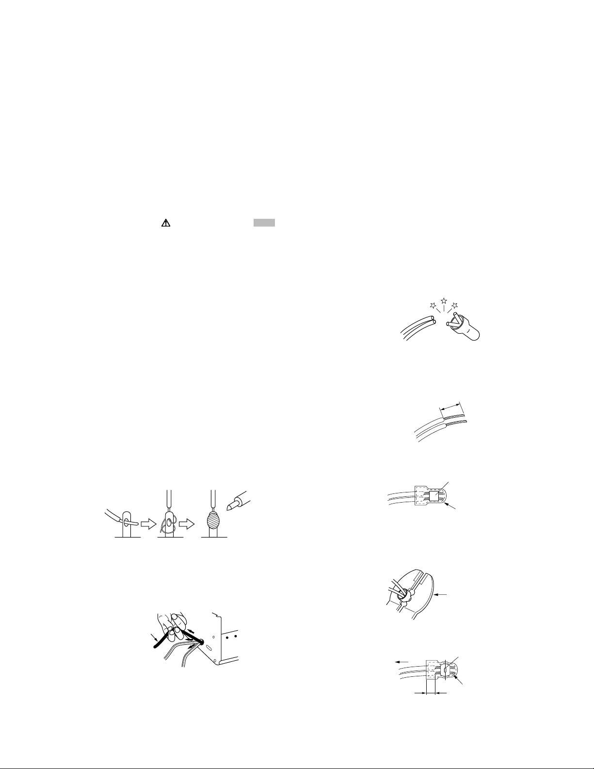
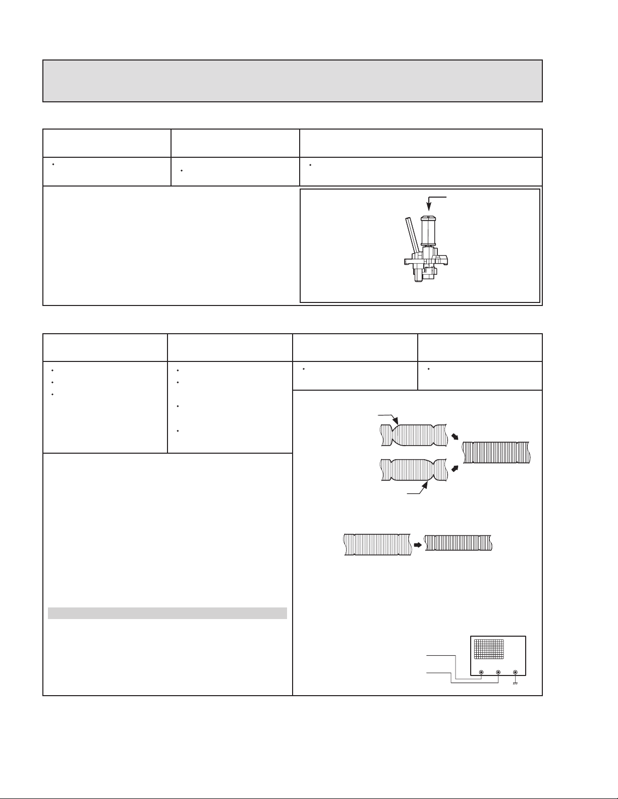
(12) Crimp type wire connectorIn such cases as when replacing
the power transformer in sets where the connections between the power cord and power trans former primary lead
wires are performed using crimp type connectors, if replacing the connectors is unavoidable, in order to prevent safety hazards, perform carefully and precisely according to the
following steps.
• Connector part number :E03830-001
• Required tool : Connector crimping tool of the proper
type which will not damage insulated parts.
• Replacement procedure
a) Remove the old connector by cutting the wires at a
point close to the connector.Important : Do not reuse a connector (discard it).
cut close to connector
Fig.1-1-3
b) Strip about 15 mm of the insulation from the ends
of the wires. If the wires are stranded, twist the
strands to avoid frayed conductors.
15 mm
Fig.1-1-4
c) Align the lengths of the wires to be connected. In-
sert the wires fully into the connector.
Metal sleeve
Fig.1-1-1
(7) Observe that wires do not contact heat producing parts
(heatsinks, oxide metal film resistors, fusible resistors, etc.)
(8) Check that replaced wires do not contact sharp edged or
pointed parts.
(9) When a power cord has been replaced, check that 10-15
kg of force in any direction will not loosen it.
Power cord
Fig.1-1-2
(10) Also check areas surrounding repaired locations.
(11) Products using cathode ray tubes (CRTs)In regard to such
products, the cathode ray tubes themselves, the high voltage circuits, and related circuits are specified for compliance with recognized codes pertaining to X-ray emission.
Connector
Fig.1-1-5
d) As shown in Fig.1-1-6, use the crimping tool to
crimp the metal sleeve at the center position. Be
sure to crimp fully to the complete closure of the
tool.
1.2
5
2
.0
5.5
Crimping tool
Fig.1-1-6
e) Check the four points noted in Fig.1-1-7.
Not easily pulled free
Wire insulation recessed
more than 4 mm
Crimped at approx. cente
of metal sleeve
Conductors extended
Fig.1-1-7
(No.YD070)1-3
Page 4
1.1.2 Safety Check after Servicing
Examine the area surrounding the repaired location for damage
or deterioration. Observe that screws, parts and wires have been
returned to original positions, Afterwards, perform the following
tests and confirm the specified values in order to verify compliance with safety standards.
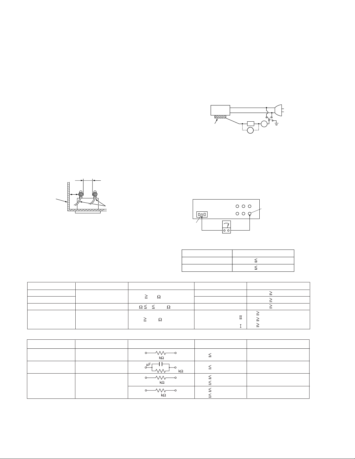
(1) Insulation resistance test
Confirm the specified insulation resistance or greater between power cord plug prongs and externally exposed
parts of the set (RF terminals, antenna terminals, video and
audio input and output terminals, microphone jacks, earphone jacks, etc.).See table 1 below.
(2) Dielectric strength test
Confirm specified dielectric strength or greater between
power cord plug prongs and exposed accessible parts of
the set (RF terminals, antenna terminals, video and audio
input and output terminals, microphone jacks, earphone
jacks, etc.). See Fig.1-1-11 below.
(3) Clearance distance
When replacing primary circuit components, confirm specified clearance distance (d), (d') between soldered terminals, and between terminals and surrounding metallic
parts. See Fig.1-1-11 below.
d
Chassis
d'
Power cord
primary wire
Fig.1-1-8
(4) Leakage current test
Confirm specified or lower leakage current between earth
ground/power cord plug prongs and externally exposed accessible parts (RF terminals, antenna terminals, video and
audio input and output terminals, microphone jacks, earphone jacks, etc.).
Measuring Method : (Power ON)Insert load Z between
earth ground/power cord plug prongs and externally exposed accessible parts. Use an AC voltmeter to measure
across both terminals of load Z. See Fig.1-1-9 and following Fig.1-1-12.
ab
Externally
exposed
accessible part
Z
V
c
A
Fig.1-1-9
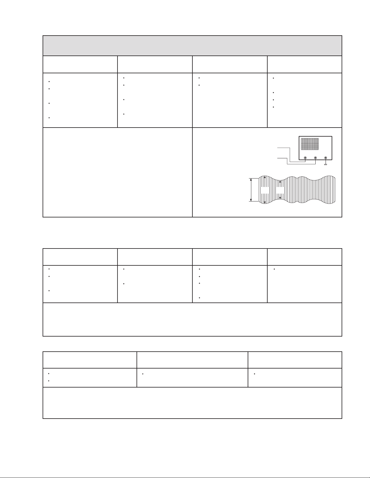
(5) Grounding (Class 1 model only)
Confirm specified or lower grounding impedance between
earth pin in AC inlet and externally exposed accessible
parts (Video in, Video out, Audio in, Audio out or Fixing
screw etc.).Measuring Method:
Connect milli ohm meter between earth pin in AC inlet and
exposed accessible parts. See Fig.1-1-10 and grounding
specifications.
AC inlet
Earth pin
Exposed accessible part
MIlli ohm meter
Grounding Specifications
Region
USA & Canada
Europe & Australia
Grounding Impedance (Z
Z 0.1 ohm
Z 0.5 ohm
)
Fig.1-1-10
AC Line Voltage
100 V
100 to 240 V
110 to 130 V
110 to 130 V
200 to 240 V
Region
Japan
USA & Canada
Europe & Australia
Insulation Resistance (R
R 1 M /500 V DC
1 M R 12 M /500 V DC
R 10 M /500 V DC
)
Dielectric Strength
AC 1 kV 1 minute
AC 1.5 kV 1 minute
AC 1 kV 1 minute
AC 3 kV 1 minute
AC 1.5 kV 1 minute
(
Class
(
Class
Clearance Distance (d), (d'
d, d' 3 mm
d, d' 4 mm
d, d' 3.2 mm
d 4 m m
)
d' 8 m m (Power cord
d' 6 m m (Primary wire
)
Fig.1-1-11
AC Line Voltage
100 V
110 to 130 V
110 to 130 V
220 to 240 V
Region
Japan
USA & Canada
Europe & Australia
Load Z
1
0.15
1.5
2
50
Leakage Current (i)
i 1 mA rms
i 0.5 mA rms
i 0.7 mA peak
i 2 mA dc
i 0.7 mA peak
i 2 mA dc
a, b, c
Exposed accessible parts
Exposed accessible parts
Antenna earth terminals
Other terminals
Fig.1-1-12
NOTE :
These tables are unofficial and for reference only. Be sure to confirm the precise values for your particular country and locality.
)
)
)
1-4 (No.YD070)
Page 5
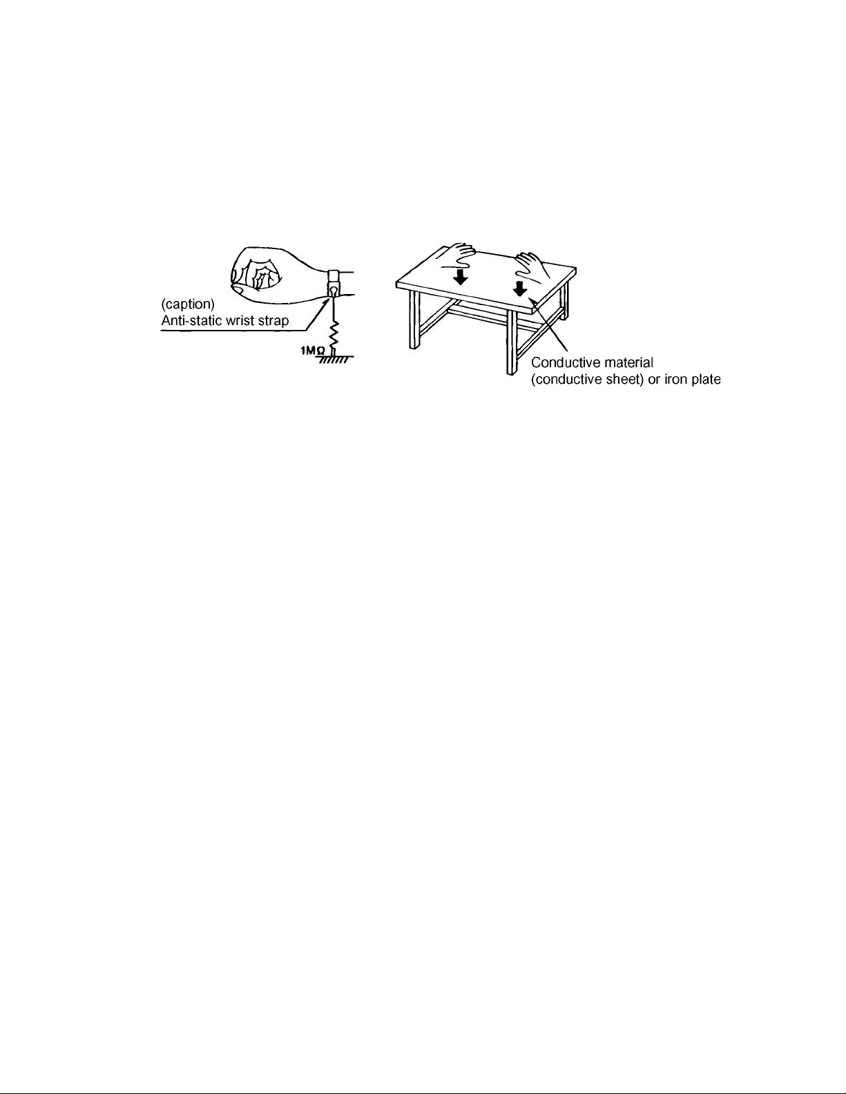
1.2 Preventing static electricity
Electrostatic discharge (ESD), which occurs when static electricity stored in the body, fabric, etc. is discharged, can destroy the laser
diode in the traverse unit (optical pickup). Take care to prevent this when performing repairs.
1.2.1 Grounding to prevent damage by static electricity
Static electricity in the work area can destroy the optical pickup (laser diode) in devices such as DVD players.
Be careful to use proper grounding in the area where repairs are being performed.
(1) Ground the workbench
Ground the workbench by laying conductive material (such as a conductive sheet) or an iron plate over it before placing the
traverse unit (optical pickup) on it.
(2) Ground yourself
Use an anti-static wrist strap to release any static electricity built up in your body.
(3) Handling the optical pickup
• In order to maintain quality during transport and before installation, both sides of the laser diode on the replacement optical
pickup are shorted. After replacement, return the shorted parts to their original condition.
(Refer to the text.)
• Do not use a tester to check the condition of the laser diode in the optical pickup. The tester's internal power source can easily
destroy the laser diode.
(No.YD070)1-5
Page 6

SECTION 2
SPECIFIC SERVICE INSTRUCTIONS
2.1 DIFFERENT TABLE OF FEATURE
The following table indicates main different points between models HR-XV45SEF, HR-XV45SEK, HR-XV45SER, HR-XV45SEU and
HR-XV45SEY/EZ.
MODEL NAME HR-XV45SEF HR-XV45SEK HR-XV45SER
SCART CABLE PROVIDED ← OPTIONAL
BROADCASTING SYSTEM PAL B/G, SECAM L PAL I, I/I, B/G, SECAM D/K, K1 ←
RF OUT CH/RF OUT
SYSTEM [INITIAL]
OSD LANGUAGES
REGIONAL CODE REGIONAL CODE : 2 ← REGIONAL CODE : 5
MODEL NAME HR-XV45SEU HR-XV45SEY/EZ
SCART CABLE OPTIONAL ←
BROADCASTING SYSTEM PAL I, I/I, B/G, SECAM D/K, K1 ←
RF OUT CH/RF OUT
SYSTEM [INITIAL]
OSD LANGUAGES
REGIONAL CODE REGIONAL CODE : 2 ←
Note:
Mark ← is same as left.
ENGLISH/GERMANY/FRENCH/
ITALIAN/SPANISH/DUTCH
ENGLISH/GERMANY/ITALIAN/
SPANISH/GREEK/PORTU-
NOT USED 22-68CH,[36CH]/I 22-68CH,[36CH]/K
ENGLISH/GERMANY/ITALIAN/
SPANISH/GREEK/PORTU-
GUESE
22-68CH,[36CH]/G ←
ENGLISH/POLISH/CZECH/
HUNGARIAN/SWEDISH/GER-
GUESE
MANY
ENGLISH/RUSSIAN
1-6 (No.YD070)
Page 7
2.2 SERVICE INFORMATION FOR EEPROM IC SETTING(VCR)
EEPROM option code No. setting EEPROM option code No. setting procedure
NAME HEX BINARY
OPT0 00 00000000
OPT1 00 00000000
OPT2 00 00000000
OPT3 00 00000000
OPT4 00 00000000
OPT5 00 00000000
12/26 - 00 V00 -COM Ver.
ID : LG
VERSION : 05 ROM
DATE : 02.17.05 Correction Ver.
MODEL NAME HEX BINARY
HR-XV45SEU OPT0 00 00000000
OPT1 F4 00000000
OPT2 60 00000000
OPT3 47 00000000
OPT4 03 00000000
OPT5 4B 00000000
HR-XV45SEK OPT0 00 00000000
OPT1 F4 00000000
OPT2 21 00000000
OPT3 87 00000000
OPT4 0D 00000000
OPT5 4B 00000000
HR-XV45SEY OPT0 00 00000000
OPT1 F4 00000000
OPT2 60 00000000
OPT3 47 00000000
OPT4 0B 00000000
OPT5 4B 00000000
HR-XV45SEZ OPT0 00 00000000
OPT1 D4 00000000
OPT2 60 00000000
OPT3 47 00000000
OPT4 0D 00000000
OPT5 4B 00000000
HR-XV45SER OPT0 09 00000000
OPT1 54 00000000
OPT2 A3 00000000
OPT3 47 00000000
OPT4 0D 00000000
OPT5 4B 00000000
HR-XV45SEF OPT0 00 00000000
OPT1 FC 00000000
OPT2 E8 00000000
OPT3 47 00000000
OPT4 0D 00000000
OPT5 4B 00000000
WR : OK I : EXIT MOVE :
EDIT :
1. DETECT NEW EEPROM (OPTION EDIT
SCREEN)
- Eeprom EDIT screen automatically appears if
replacing Eeprom.
- Setup option data using the cursor Up/Down key
of a remote control.
(Setup upon BOM depending on OPT0~OPT5
model)
Since an initial remote control is set to LG for LG
model, appropriately set optiona data using the
cursor Up/Down key.
2. EEPROM WRITED AND EEPROM INITIAL
- Writes data on EEPROM by using REMOCON
"OK" + FRONT PLAY KEY FOR MORE THAN 5
SECONDS.
3. PG ADJUST
1) Payback the SP standard tape
2) Press the "OK" key on the Remote controller
and the "PLAY" key on the Front Panel the
same time, then it goes in to Tracking initial
mode.
3) Repeat the above step(No.2), then it finishes
the PG adjusting automatically.
4) Stop the playback, then it goes out to PG
adjusting mode after mony the PG data.
4. BUYER SELECTION
- Font ejection key + open/close key for more than
5 seconds.
- Option code is displayed in TV
- First byte of OPTO is changed whenever front
eject key + open/close key.
- JVC remote conroller No.0.
(No.YD070)1-7
Page 8
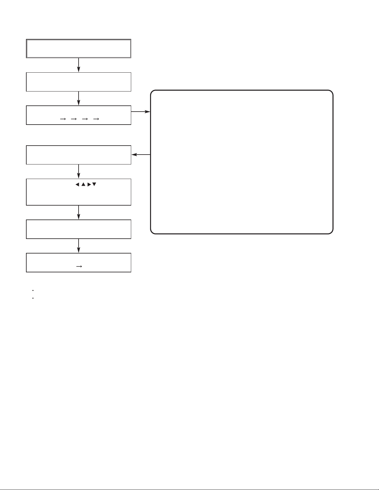
2.3 SERVICE INFORMATION FOR EEPROM (DVD)
POWER ON
DVD LOGO Status (NO Disk status)
DETECT NEW EEPROM
(OPTION EDIT SCREEN)
Remote control
Pause key 1 4 7 2 in order.
Press number 0~9, Press charater
A~F (1~6 for a while)
Use arrow key ( ) to move
to approprite position and make
changes
Press pause key once
Change will be applied when power
OFF ON.
MODEL
NAME HEX HEX HEX HEX HEX HEX
OPT 1 44 47 53 50 52 42
OPT 2 45 42 45 4C 55 45
OPT 3 00 00 00 00 00 00
OPT 4 D3 D3 D3 D3 D3 D3
OPT 5 12 12 12 12 12 12
OPT 6 05 05 05 05 05 05
OPT 7 B0 B0 B0 B0 B0 B0
OPT 8 00 00 00 00 00 00
OPT 9 00 00 00 00 00 00
OPT A 00 00 00 00 00 00
OPT B 80 80 80 80 80 80
OPT C 00 00 00 00 0A 00
OPT D 00 00 00 00 00 00
OPT E 00 00 00 00 00 00
OPT F 00 00 00 00 00 00
OPT G 00 00 00 00 00 00
HR-XV45SEU HR-XV45SEK HR-XV45SEY HR-XV45SEZ HR-XV45SER HR-XV45SEF
* OPTION
NTSC model does not have VCR option and use DVD option B~F as VCR option. (only DVD exist)
PAL model has another separate VCR option. (Both VCR and DVD exist)
1-8 (No.YD070)
Page 9

SECTION 3
DISASSEMBLY
This service manual does not describe DISASSEMBLY.
(No.YD070)1-9
Page 10
SECTION 4
ADJUSTMENT
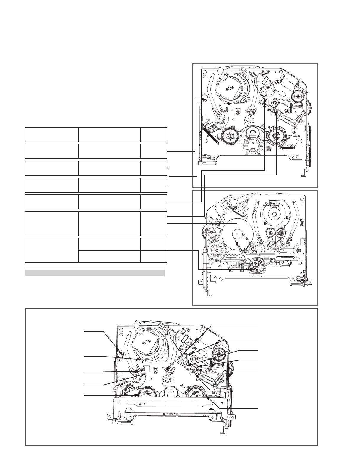
4.1 POSITION DRAWING OF DECK MECHANISM PARTS (VCR)
Top View
9
2
6
11
1
33
14
15
7
35
4
3
5
10
8
12
18
16
17
19
13
15
Bottom View
20
21
24
21
24
23
22
30
NOTE : Assembly order is a reverse of
disassembly order.
26
32
31
31
32
25
34
28
27
29
Order Of Dis-
assembled
Parts firstly
Disassembled
1
Drum Assembly
2
Plate Top
2
2,3
2,3,4
2,3,4,5
2,3
2,3
2,3,13,14
17
17
17,18
21,22
21
21,22,23,
24,25,26
21,22,23,
24,25,26,27
21,22,23,
24,25,26,27
21,22,23,
24,25,26,27
25
2,3,14,
25,31
25,31
2,3,14
3
Holder Assembly CST
4
Gear Assembly Rack F/L
5
Opener Door
6
Arm Assembly F/L
7
Lever Assembly S/W
8
Motor Assembly L/D
9
Gear Wheel
10
Arm Assembly Cleaner
11
Head F/E
12
Base Assembly A/C Head
13
Brake Assembly T
14
Arm Assembly Tension
15
Reel S / Reel T
16
Base Assembly P4
17
Opener Lid
18
Arm Assembly Pinch
19
Arm T/up
20
Supporter, capstan
21
Belt Capstan/Motor Capstan
22
Lever F/R
23
Clutch Assembly D37
24
Gear Drive/Gear Cam
25
Gear Sector
26
Brake Assembly Capstan
27
Plate Slider
28
Lever Tension
29
Lever Spring
30
Lever Brake
Gear Assembly P2/
31
Gear Assembly P3
Base Assembly P2
32
/Base Assembly P3
33
Base Loading
34
Base Tension
35
Arm Assembly Idler Jog
T:Top, B:Bottom
Part
Ref.
Fixing Type
Draw-
ings
3 screws
2 hooks
6 chasses
1 hook
Chassis Hole
Chassis Hole
Chassis Hole,
1 hook
1 screw
2 hooks
Chassis Embossing
Chassis Embossing
1 screw
1 hook
1 hook
Shaft
Chassis Embossing
Chassis Embossing
Shaft
1 hook
Chassis Hole
3 screws
Ta b
Washer
Washer/Hook
Hook
Chassis Hole
Chassis Guide
1 Hook
1 Hook
1 Hook
Bass
6 Chasses
3 Hooks
Chassis Embossing
Locking Tab
A-1
A-2
A-2
A-2
A-2
A-2
A-2
A-3
A-3
A-3
A-3
A-3
A-4
A-4
A-4
A-5
A-5
A-5
A-5
A-6
A-6
A-6
A-6
A-7
A-7
A-7
A-7
A-7
A-7
A-7
A-8
A-8
A-8
A-9
A-9
Posi
tion
T
T
T
T
T
T
T
T
T
T
T
T
T
T
T
T
T
T
T
B
B
B
B
B
B
B
B
B
B
B
B
B
B
T
T
(1) For assembly, check the assembly mode is accurate.
(2) Parts firstly disassembled indicate parts firstly disassembled
in disassembly of related parts.
1-10 (No.YD070)
Page 11
4.2 DISASSEMBLY AND ASSEMBLY OF DECK MECHANISM (VCR)
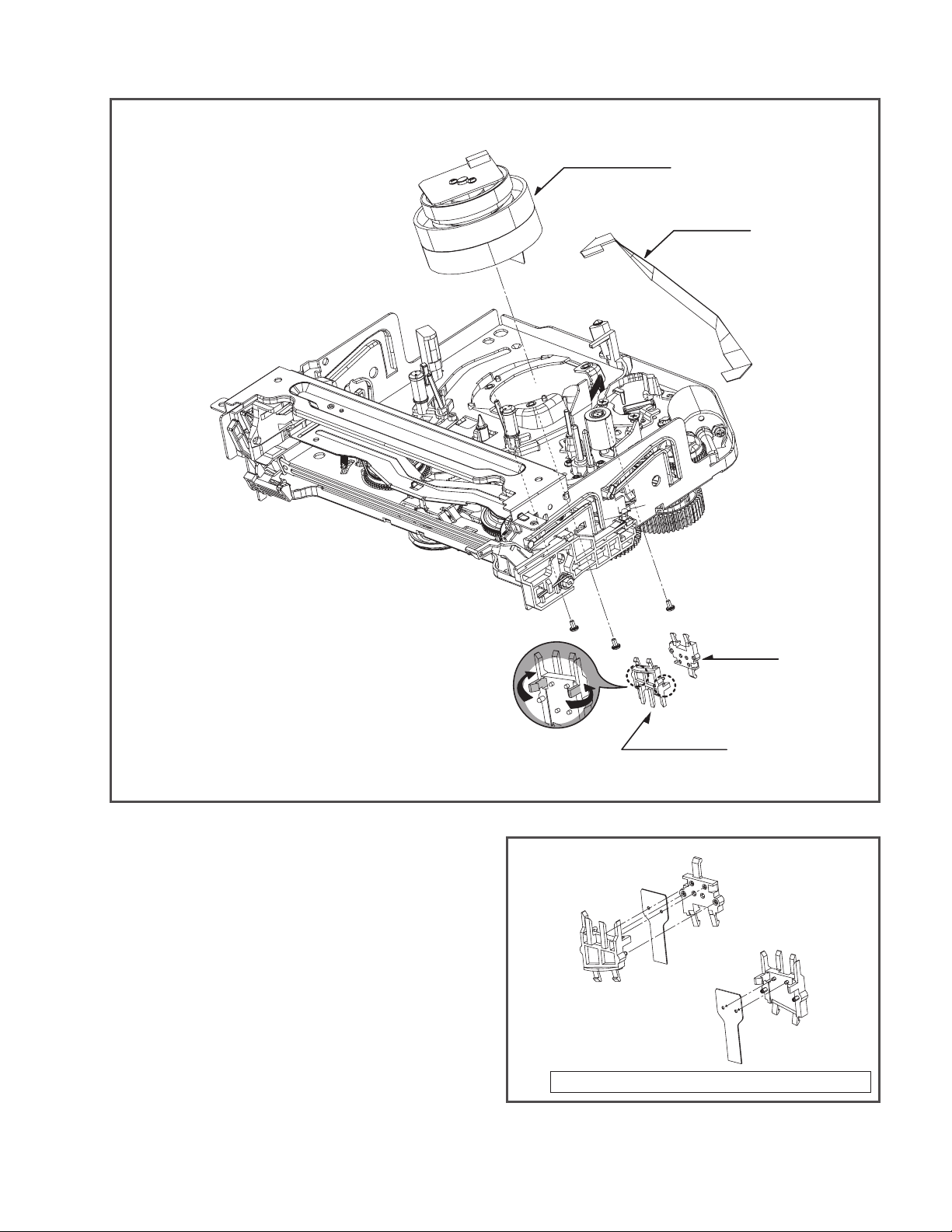
Drum Assembly
Cable Flat
1. Disassembly of Drum Assembly
(Figure A-1)
1) Separate cable flat from the Drum FPC and the Capstan
Motor.
2) Release 3 screws (S1) on the bottom side of the chassis,
and separate the drum assembly.
3) Release the hooks (H1, H2) and separate both the holder
FPC and the Cap FPC (disassemble if necessary).
(S1)
H2
Fig. A-1
Cautions in assembly of FPC
Holder FPC
(S1)
(S1)
Cap, FPC
H1
Holder FPC
Cap FPC
Drum FPC
Assembly shape seen in the reverse direction
(No.YD070)1-11
Page 12
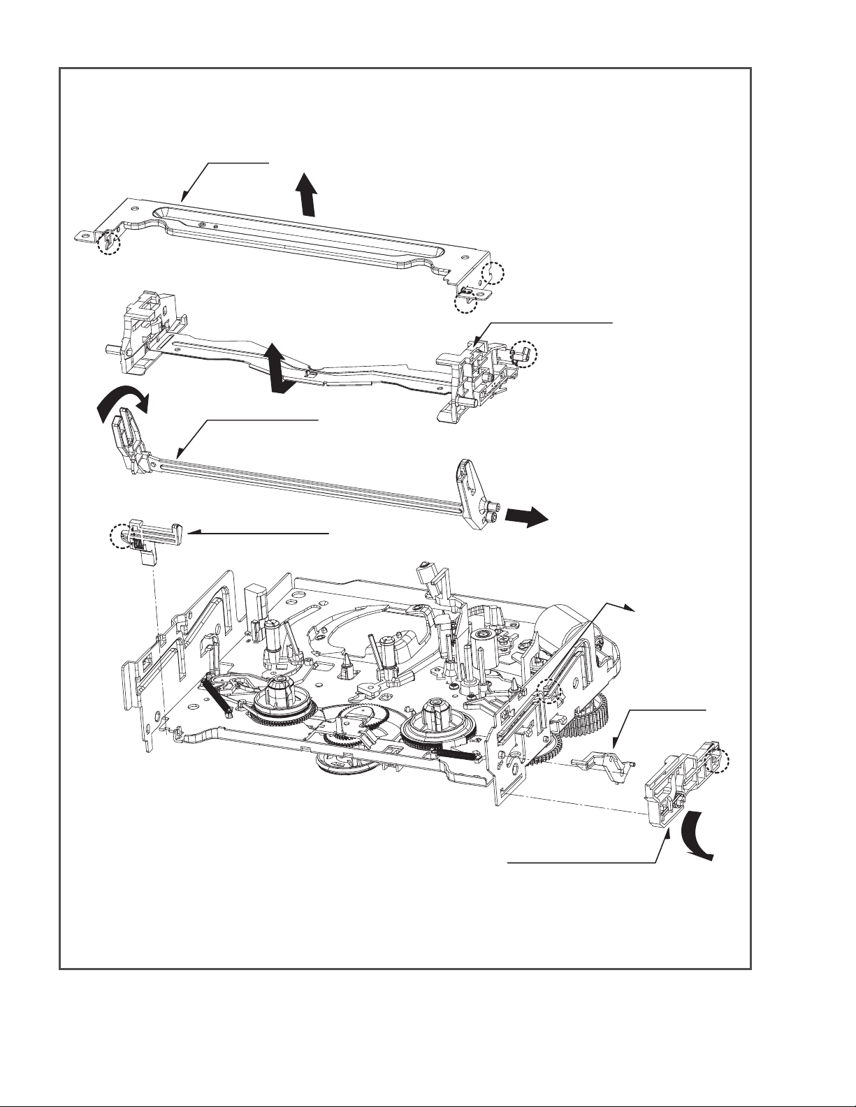
Plate Top
(Fig. A-2-1)
(H4)
(B')
Arm Assembly F/L
(Fig. A-2-5)
Lever Assembly S/W
(Fig. A-2-6)
(B)
(C)
Holder Assembly CST
(Fig. A-2-2)
(E)
(E)
1-12 (No.YD070)
Fig. A-2
Gear Assembly Rack F/L
(Fig. A-2-3)
Opener Door
(Fig. A-2-4)
(A)
(H3)
(B)
Page 13
2. Disassembly of Plate Top (Fig. A-2-1)
1) Separate the right part while leaning back the (B) part of
the plate top toward the arrow direction.
2) Separate the left part while leaning back the (B f) part of
the plate top toward the arrow direction.
(Tool used: Tool such as (-) driver, auger, etc with pointed
or flat end)
CAUTIONS
Assemble while pressing the (C), (C') part after corresponding them as in drawing.
(C')
(C)
(B')
(B)
3. Holder Assembly CST (Fig. A-2-2)
1) Firstly separate the left part from the groove on the (D)
part of chassis while moving the holder assembly CST
toward the arrow direction.
Holder Assembly CST
(D)
Chassis
4. Disassembly of Gear Assembly
Rack F/L (Fig. A-2-3)
1) Separate the hook (H3) while leaning ahead the hook (3)
after moving the gear assembly rack F/L toward the arrow
(A) direction.
2) Separate the gear assembly rack F/L toward the arrow (B)
direction.
CAUTIONS
For the assembly, correspond the gear part of gear assembly
rack F/L to the gear drive.
Gear Rack F/L
Gear Drive
5. Opener Door (Fig. A-2-4)
1) Separate the opener door ahead from the guide hole of
chassis while turning it clockwise.
6. Arm Assembly F/L (Fig. A-2-5)
1) Firstly separate the left part of the arm assembly F/L from
the groove of chassis while pushing the arm assembly F/L
toward the arrow direction.
2) Separate the right part from the groove of chassis.).
2) Separate the right part from each groove of chassis
CAUTIONS
Assemble by inserting the left part after firstly inserting the
(E) part of the holder assembly CST into the groove on the
(E') part of chassis.
7. Lever Assembly S/W (Fig. A-2-6)
1) Separate the lever assembly S/W while pushing it toward
the arrow direction after removing the hook (4) on the left
side of chassis.
Chassis
(H4)
(No.YD070)1-13
Page 14
Base Assembly A/C Head
(Fig. A-3-5)
(A)
Arm Assembly Cleaner
(Fig. A-3-3)
(A)
(S5)
(H5)
Gear Wheel
(Fig. A-3-2)
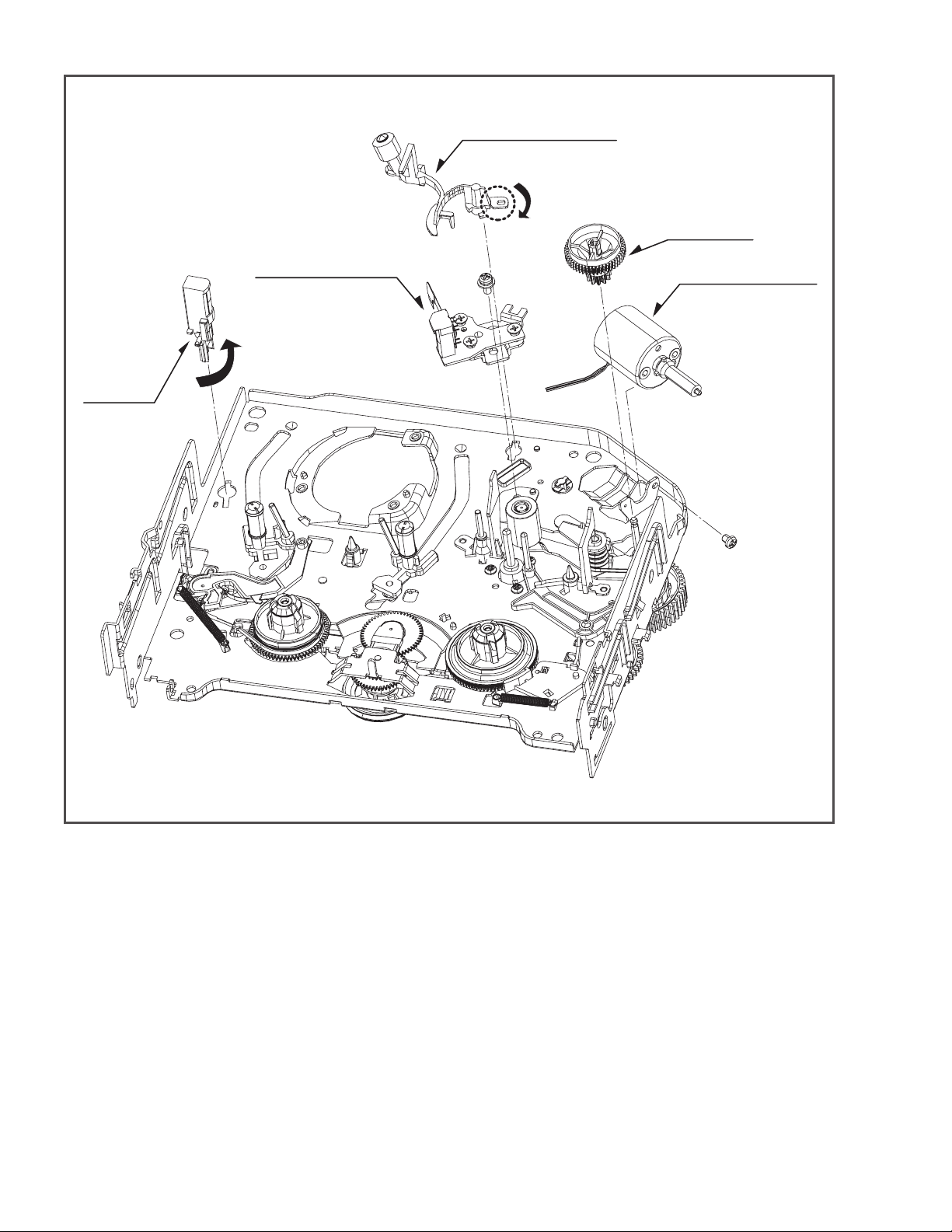
Motor Assembly L/D
(Fig. A-3-1)
Head F/E
(Fig. A-3-4)
(C1)
(S4)
Fig. A-3
8. Motor Assembly L/D (Fig. A-3-1)
1) Take the connector (C1) connected to the Capstan motor
PCB out.
2) Remove a screw (S4) of the chassis (S4) and step back ward, and disassemble it while holding it up.
9. Gear Wheel (Fig. A-3-2)
1) Release the hook (H5) of the gear wheel and disassemble
it upward.
1-14 (No.YD070)
10. Arm Assembly Cleaner (Fig. A-3-3)
1) Separate the (A) part of Fig. A-3-1 from the embossing of
chassis, and hold it up while turning it anti-clockwise.
11. Head F/E (Fig. A-3-4)
1) Separate the (A) part of the head F/E from the embossing of chassis, and hold it up while turning it anti-clockwise.
12. Base Assembly A/C Head (Fig. A-3-5)
1) Release a screw (S5) and disassemble while holding it up.
Page 15
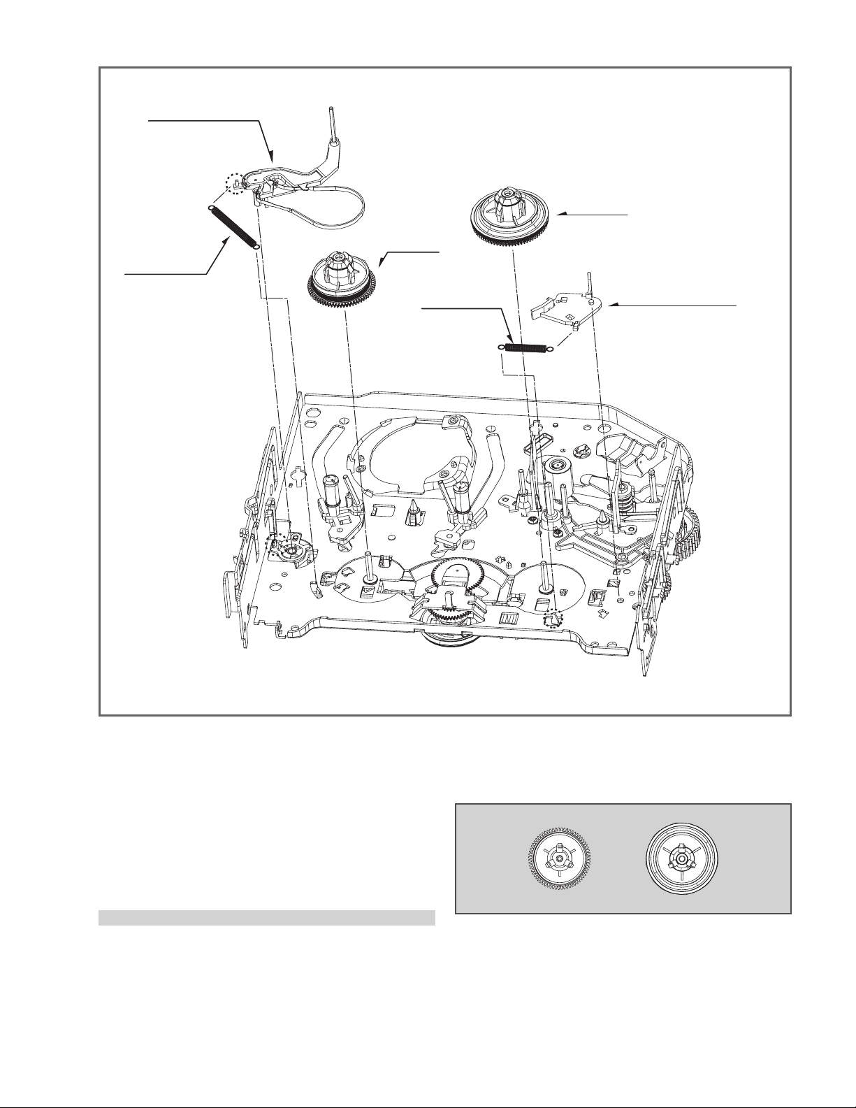
Arm Assembly Tension
(Fig. A-4-2)
Spring Tension
(H7)
Reel T
(Fig. A-4-3)
Reel S
(Fig. A-4-3)
(H8)
Spring Tension
Fig. A-4
Brake Assembly T
(Fig. A-4-1)
(H6)
13. Brake Assembly T (Fig. A-4-1)
1) Release the spring tension from the lever spring hook
(H6).
2) Disassemble the brake assembly T while holding it
upward.
14. Arm Assembly Tension (Fig. A-4-2)
1) Release the spring tension the hook (H7) from the arm
assembly tension.
2) After releasing the hook (H8) of the base tension, separate
it while holding it up.
CAUTIONS
Spring used for both brake assembly T and arm assembly
tension is used (2EA used).
15. Reel S/Reel T (Fig. A-4-3)
1) Disassemble the reel S/ reel T while holding it up (compa rison between Reel S and Reel T)
Reel S Reel T
(No.YD070)1-15
Page 16
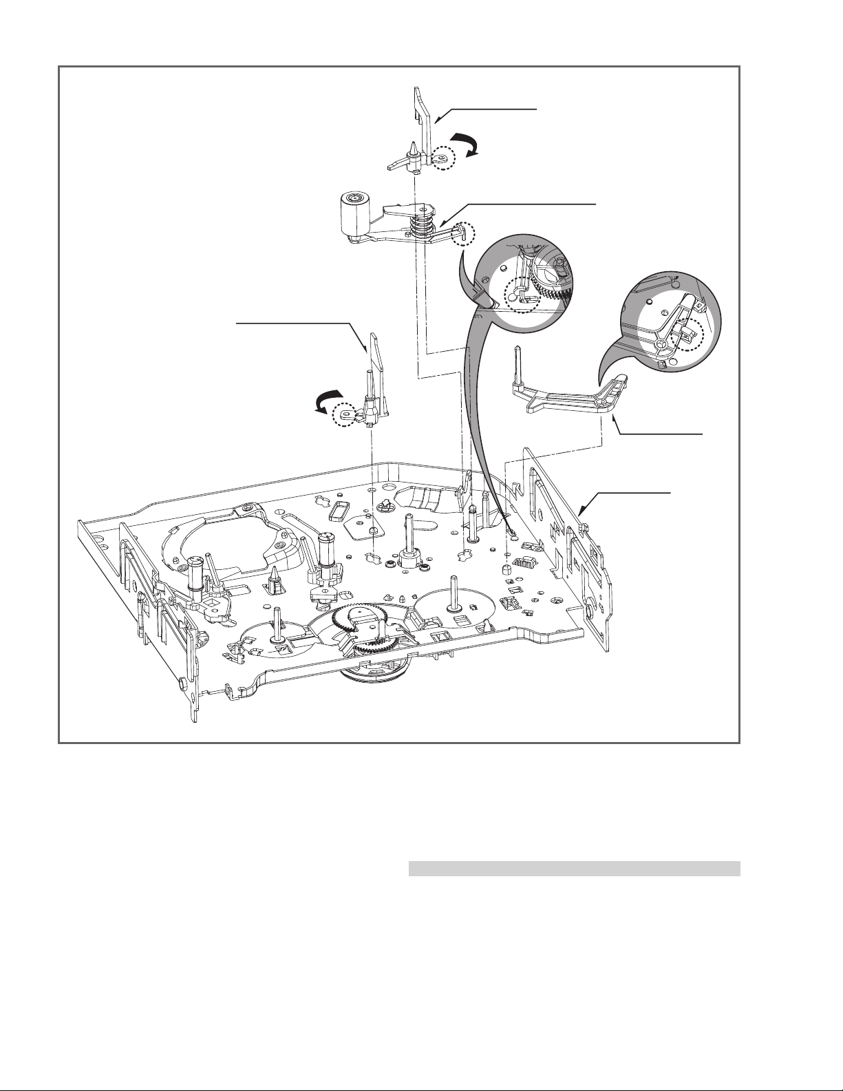
(Fig. A-5-2)
(B)
Opener Lid
Arm Assembly Pinch
(Fig. A-5-3)
(C)
Base Assembly P4
(Fig. A-5-1)
(A)
(C)
(H9)
Arm T/up
(Fig. A-5-4)
Chassis
16. Base Assembly P4 (Fig. A-5-1)
1) Release the (A) part of the base assembly P4 from the
embossing of chassis.
2) Hold the base assembly P4 up while turning it anti-clock wise.
17. Opener Lid (Fig. A-5-2)
1) Release the (B) part of the opener lid from the embossing
of chassis.
2) Disassemble the opener lid upward while turning it anticlo ckwise.
1-16 (No.YD070)
Fig. A-5
18. Arm Assembly Pinch (Fig. A-5-3)
1) Hold the arm assembly pinch up.
19. Arm T/up (Fig. A-5-4)
1) Turn the arm T/up to release the anchor jaw (H9) part of
chassis and then hold it upward.
CAUTIONS
For the assembly, check the (C) part of the arm assembly
pinch is assembled as in drawing.
- REVERSE THE MECHANISM.
Page 17
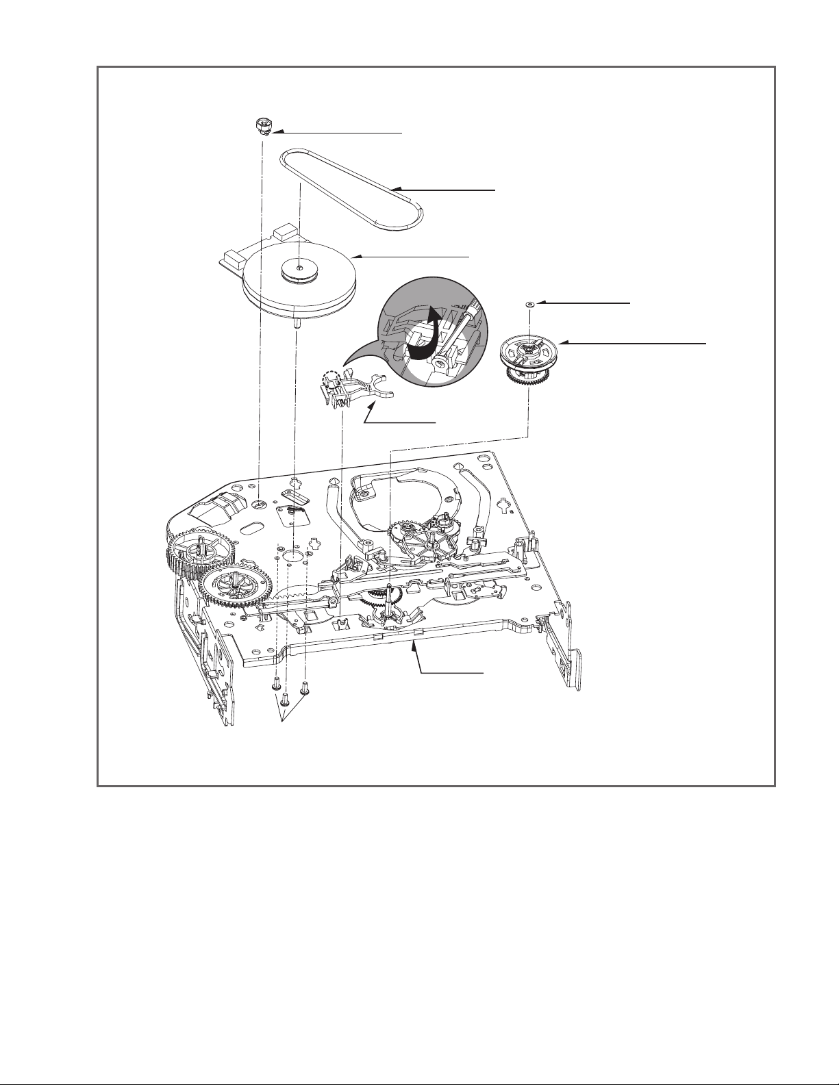
Suppoter Capstan
(Fig. A-6-1)
Motor Capstan
(L1)
Lever F/R
(Fig. A-6-4)
Belt Capstan
(Fig. A-6-2)
(Fig. A-6-3)
Washer(W1)
Clutch Assembly D37
(Fig. A-6-5)
(L1)
(S6)
Fig. A-6
20. Supporter, Capstan (Fig. A-6-1)
1) Turn the supporter and Capstan by 90 deg. clockwise
with a driver for disassembly.
21. Belt Capstan (Fig. A-6-2) /
Motor Capstan (Fig. A-6-3)
1) Separate the belt Capstan.
2) Undo 3 screws (S6) on the bottom side of chassis and dis assemble it upward.
Chassis
22. Lever F/R (Fig. A-6-4)
1) Release the locking tab (L1) and then disassemble it
upward.
23. Clutch Assembly D37 (Fig. A-6-5)
1) Remove the washer (W1) and then disassemble it
upward.
(No.YD070)1-17
Page 18
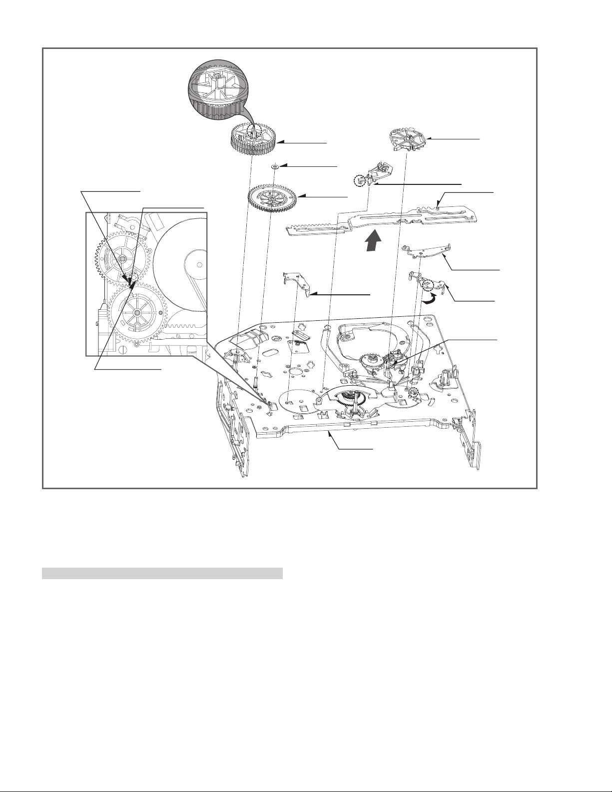
(H10)
(Fig. A-7-2)
(W2)
Gear Cam
Washer (W2)
(H11)
Gear Sector
(Fig. A-7-3)
Gear Cam Hole(B)
Gear Cam Hole(C)
Gear Drive Hole(A)
Gear Drive
(Fig. A-7-1)
Lever Brack
(Fig. A-7-8)
(L2)
Chassis
Brake Assembly Capstan
(Fig. A-7-4)
(Fig. A-7-5)
(Fig. A-7-6)
(B)
(Fig. A-7-7)
3 6
Plate Slider
Lever Tension
Lever spring
Base Loading
Fig. A-7
24. Gear Drive (Fig. A-7-1)/Gear Cam (Fig. A-7-2)
1) Remove the washer (W2) and then disassemble the
gear drive.
2) Release the hook (H10) of the gear cam and then disas semble it upward.
CAUTIONS
For the assembly, adjust both the gear driver hole (A) and
the gear cam hole (B) straightly and then correspond the
gear cam hole (C) to the chassis hole.
25. Gear Sector (Fig. A-7-3)
1) Release the hook (H11) of the gear sector and then hold
the gear sector upward.
26. Brake Assembly Capstan (Fig. A-7-4)
1) Release the locking tab (L2) on the bottom side of the
plate slider and then disassemble it upward.
27. Plate Slider (Fig. A-7-5)
1) Disassemble the plate slider while holding it up.
28. Lever Tension (Fig. A-7-6)
1) Release the lever tension from the guide (A) of chassis
while turning it anti-clockwise.
2) Disassemble the lever tension while holding it up.
29. Lever Spring (Fig. A-7-7)
1) Release the (B) part of the lever spring from the guide
(A) of chassis while turning it anti-clockwise.
2) Disassemble the lever tension while holding it up.
30. Lever Brake (Fig. A-7-8)
1) Disassemble the lever brake while holding it up.
1-18 (No.YD070)
Page 19
Gear assembly P2 Hole
Gear assembly P3 Hole
Lever Tension Boss
Gear sector (A)
Plate slider Hole(B)
(H12)
(H14)
Gear Assembly P3
(Fig. A-8-2)
Gear Assembly P2
(Fig. A-8-1)
(H13)
Base Loading
(Fig. A-8-5)
Chassis
Base Assembly P3
(Fig. A-8-4)
31. Gear Assembly P2 (Fig. A-8-1)/
Gear Assembly P3 (Fig. A-8-2)
1) Hold the gear assembly P2 upward.
2) Hold the gear assembly P3 upward.
CAUTIONS
For the assembly, check the holes of both the gear assembly P2 and the P3 are adjusted straightly, and then correspond the gear section groove (A) to the plate slider hole (B).
(B)
(A)
Base Assembly P2
(Fig. A-8-3)
Fig. A-8
32. Base Assembly P2 (Fig. A-8-3)/
Base Assembly P3 (Fig. A-8-4)
1) Disassemble the base assembly P2 downward while mov ing it toward the arrow (A) direction along with the guide
hole of chassis.
2) Disassemble the base assembly P2 downward while mov ing it toward the arrow (B) direction along with the guide
hole of chassis.
33. Base Loading (Fig. A-8-5)
1) Release 3 hooks (H12, 13, 14) of the base loading, and
then disassemble them upward.
- REVERSE THE MECHANISM.
(No.YD070)1-19
Page 20
Base Tension
(Fig. A-9-1)
(A)
Arm Assembly Idler Jog
(Fig. A-9-2)
(B) (C)
(D)
34. Base Tension (Fig. A-9-1)
1) Release the (A) part of the base tension from the
embossing of chassis.
2) Hold the base tension upward while turning it anti-clock wise.
Chassis
Fig. A-9
35. Arm assembly Idler Jog (Fig. A-9-2)
1) Push both (B), (C) parts in Fig. A-9-2 toward the arrow
direction.
2) Disassemble the arm assembly idler upward.
CAUTIONS
Take care to ensure that the (D) part in the drawing is not
hung to chassis in disassembly.
1-20 (No.YD070)
Page 21
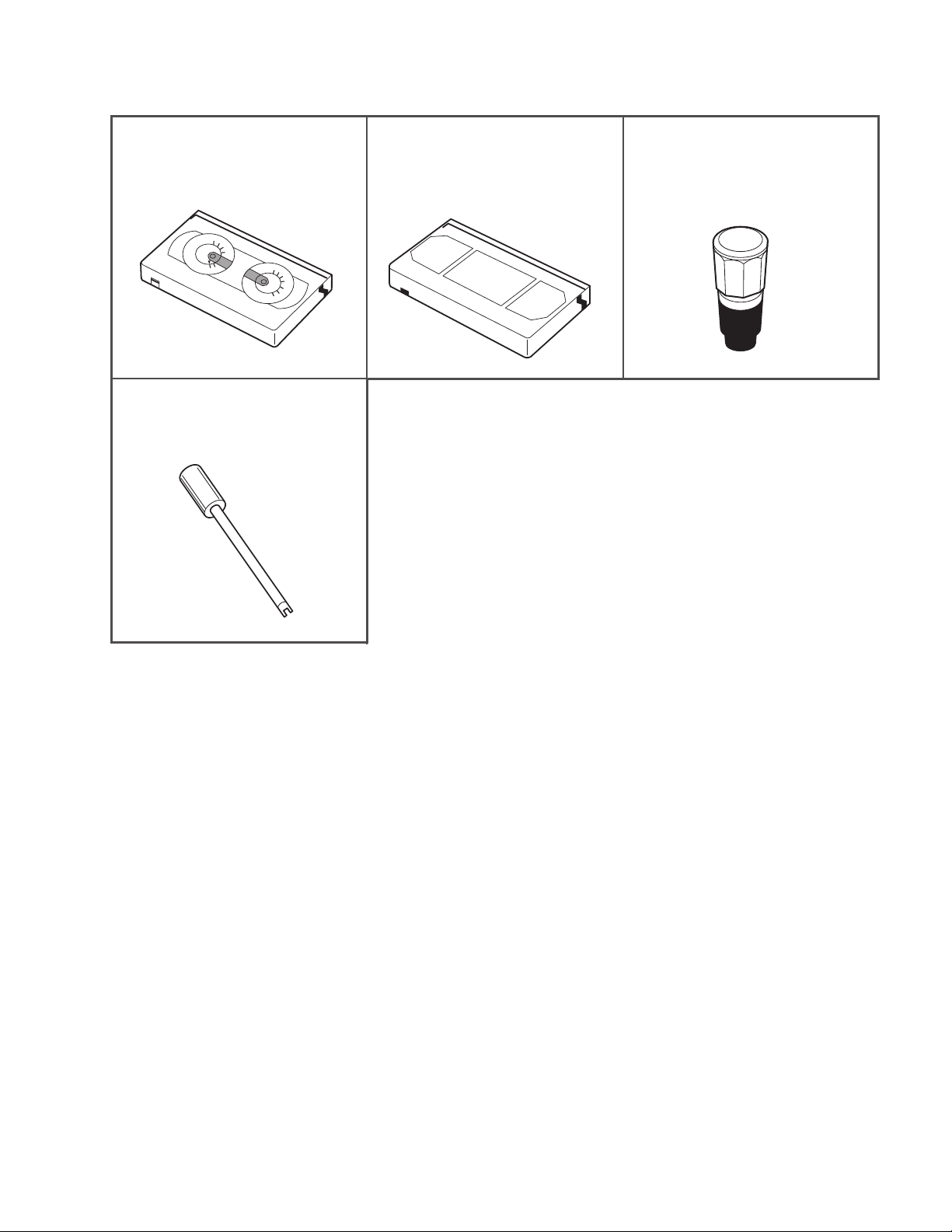
4.3 DECK MECHANISM ADJUSTMENT (VCR)
4.3.1 Tools and Fixfures for Service
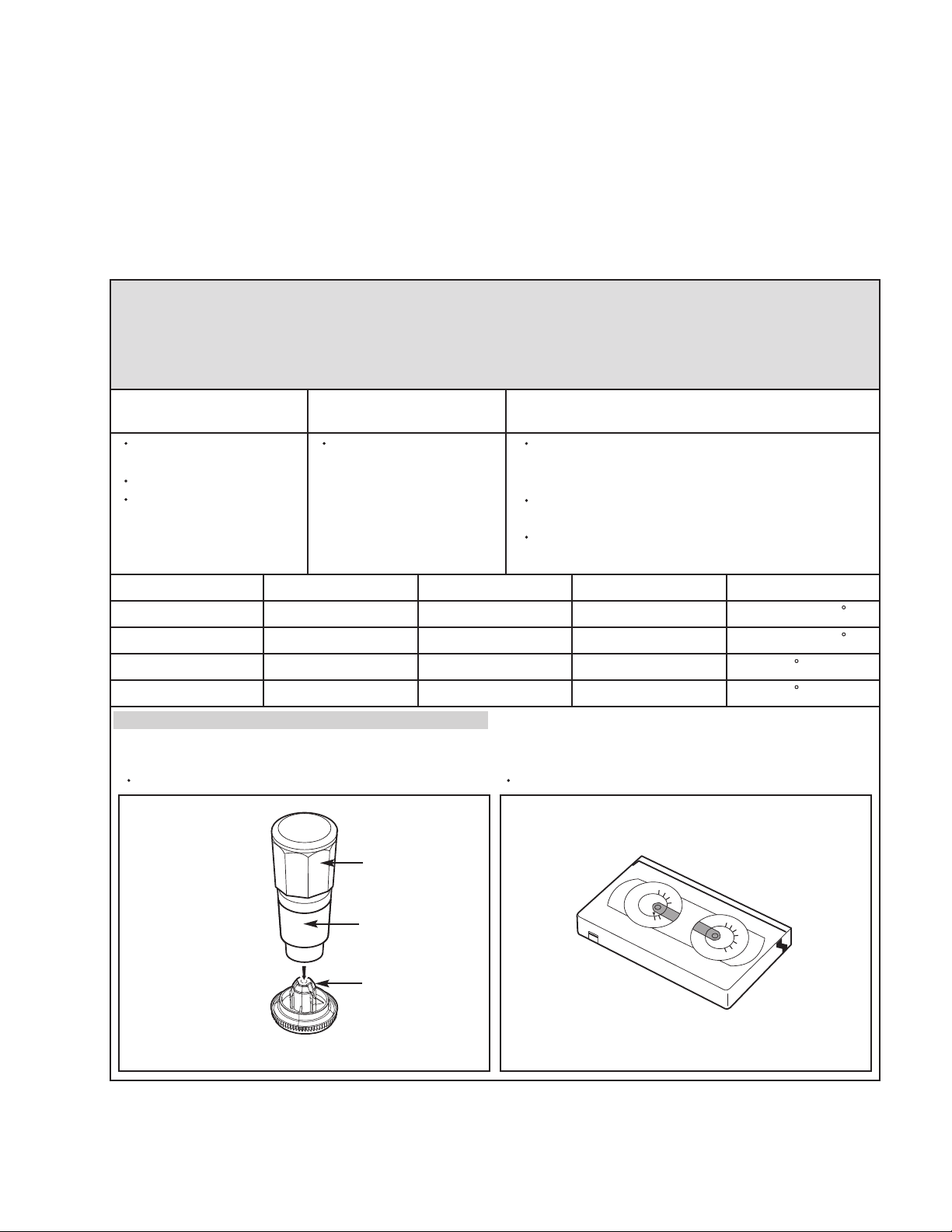
1. Cassette Torque Meter
1. PUJ42881
1.
300
S
-
T
2
50
H
V
-
20
0
K
R
15
0
S
SRK
VIDEO
CASSETTE
H
V
T
-
-
K
T
R
0
TORQUE
S
50
0
METER
VHT-303
50
15
0
2
00
25
0
300
5. Post Height Adjusting Driver
(Roller driver)
PTU94002
2. Alignment Tape
NTSC: MHP
PAL: MHPE
3. Torque Gauge
3. PUJ48075-2
(No.YD070)1-21
Page 22
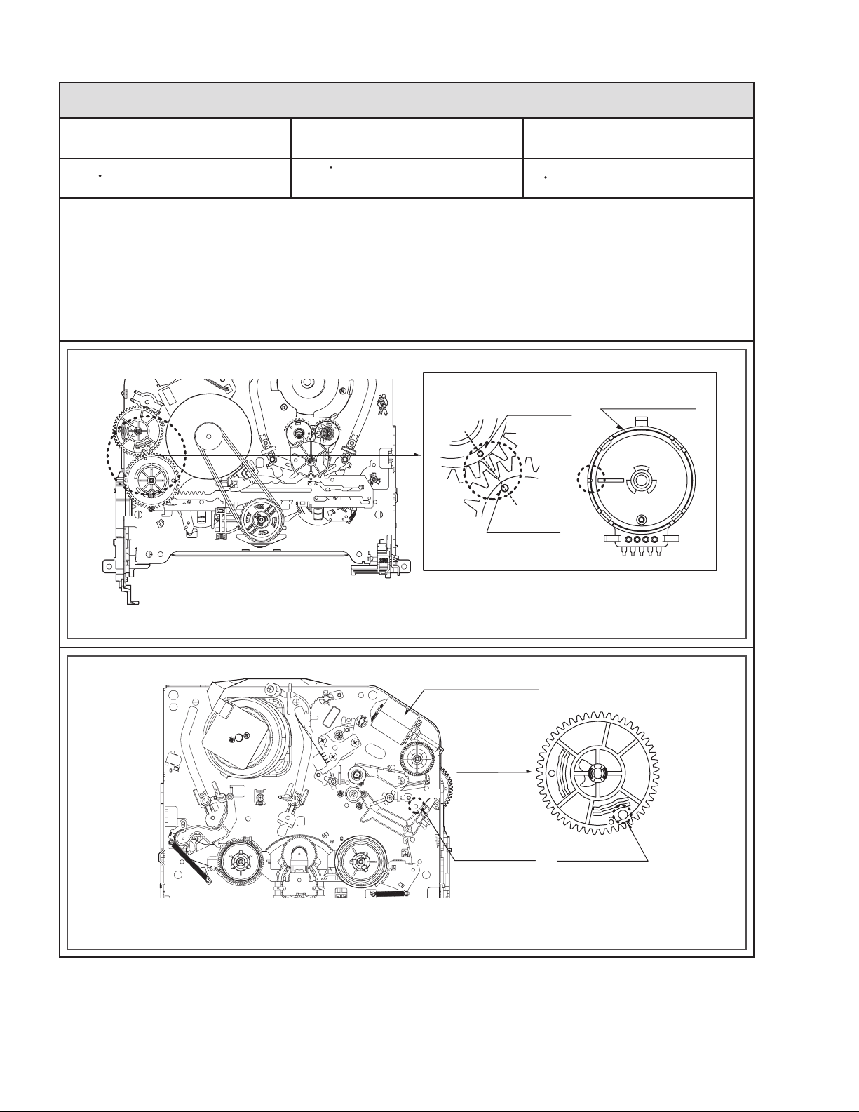
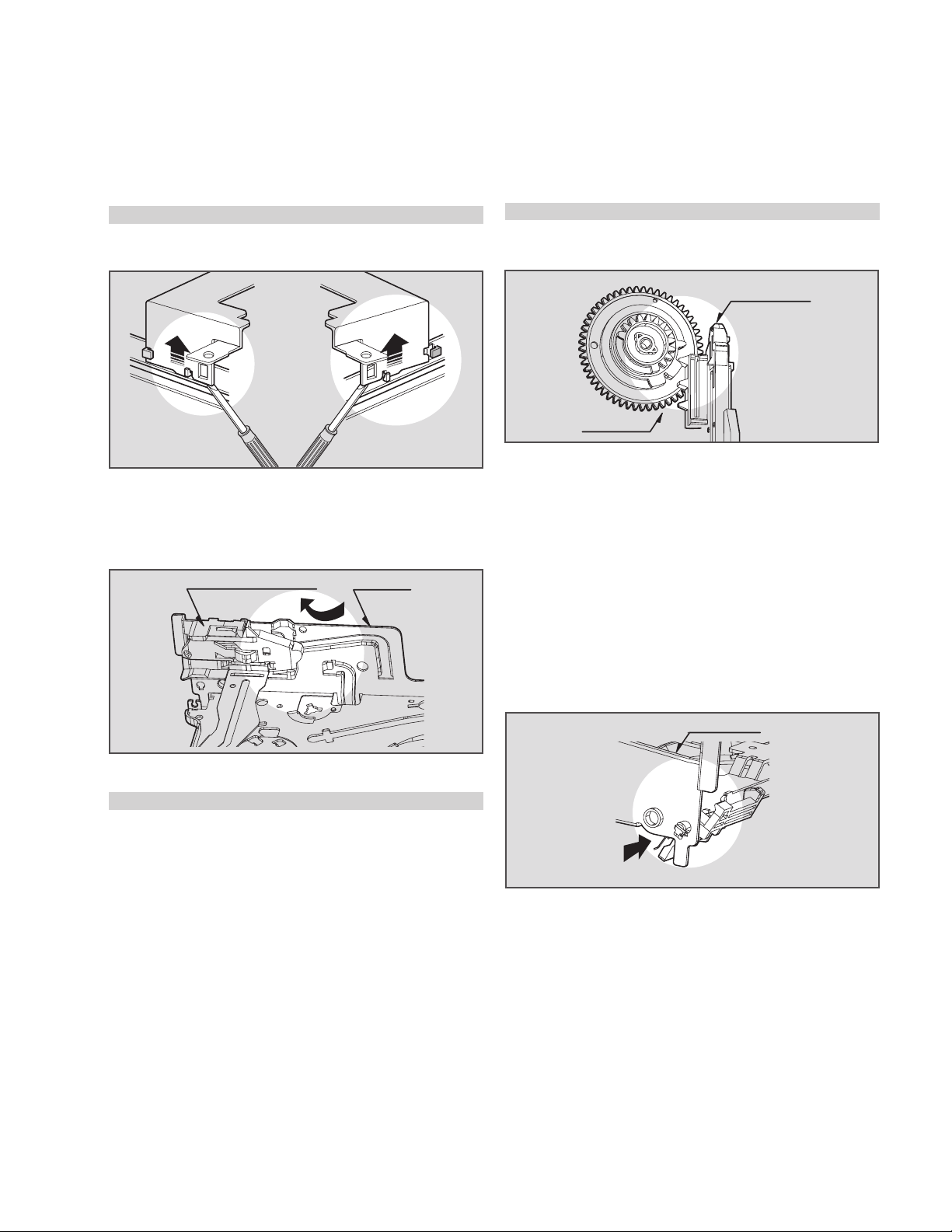
4.3.2 Mechanism Assembly Mode Check
Purpose of adjustment : To make tools normally operate by positioning tools accurately.
Fixtures and tools used VCR (VCP) status Checking Position
Blank Tape (empty tape)
Eject Mode
(with cassette withdrawn)
1) Turn the VCR on and take the tape out by pressing the
eject button.
2) Separate both top cover and plate top, and check both
the hole (A) of gear cam and the hole (A') of chassis co rrespond (Fig. C-2).
3) If it is done as in the paragraph 2): Turn the gear cam as
in No.2) after mantling the motor assembly L/D.
CHECK DIAGRAM
Mechanism and Mode Switch
4) Undo the screw fixing the deck and the main frame, and
separate the deck assembly. Check both the hole (A) of
gear cam and the hole (A') of chassis correspond (Fig.
C-1).
5) Check the mode S/W on the main P.C. board locates at
a proper position as in (B) of the Fig. (C-1).
6) Connect the deck to the main P.C. board and perform all
types of test.
Gear Cam
(C)
Gear Drive
(B)
Mode S/W
BOTTOM VIEW
TOP VIEW
Fig. C-1
Fig. C-2
Correspondence of the gear cam hole (O)
and the gear drive hole (O)
Motor Assembly L/D
Gear Cam
(A')
(A)
Chassis Hole
Gear Cam Hole
1-22 (No.YD070)
Page 23
4.3.3 Previous Preparation for Deck Adjustment
(Preparation to load the VCR (VCP) with cassette tape not inserted)
(1) Take the power cord from the consent.
(2) Separate the top cover and the plate assembly top.
(3) Insert the power cord into again.
(4) Turn the VCR (VCP) on and load the cassette while push-
ing the lever stopper of the holder assembly CST back-
If doing so, proceeding to the stop mode is done. In this status,
input signals of all modes can be received. However, operation
of the Rewind and the Review is impossible since the take-up
reel remains at stop status and so cannot detect the reel pulse
(however, possible for several seconds).
ward. In this case, clog both holes on the housing rail part
of chassis to prevent detection of the end sensor.
4.3.4 Torque Measuring
Purpose of Measuring : To measure and check the reel torque on the take-up part and the
supply part that performs basic operation of the VCR (VCP) for
smoothly forwarding the tape.
Measure and check followings when the tape is not smoothly
wound or the tape velocity is abnormally proceeded:
VCR (VCP) status Measuring methodFixtures and tools used
Torque Gauge
(600 g.cm ATG)
Torque Gauge Adaptor
Cassette Torque Meter
Play (FF) or Review
(REW) Mode
Try to operate the VCR (VCP) per mode with the
tape not inserted (See 4.3.3 Prior Preparation for
Deck Adjustment).
Measure after adhering and fixing the torque
gauge adaptor to the torque gauge (Fig. C-3-1)
Read scale of the supply or take-up part of the
cassette torque meter (Fig. C-3-2).
Item
Fast forward Torque
Rewind Torque
Play Take-Up Torque
Review Torque
Fast Forward
Rewind
Play
Review
Mode Instruments Reel Measured Measuring Value
Torque Gauge
Torque Gauge
Cassette Torque Meter
Cassette Torque Meter
Take-Up Reel
Supply Reel
Take-Up Reel
Supply Reel
NOTE
Adhere the torque gauge adaptor to the torque gauge for measuring the value.
Cassette Torque MeterTorque Gauge (600g.cm ATG)
Torque Gauge
Torque Gauge
Adaptor
More than 400g cm
More than 400g cm
40~100g cm
40~210g cm
300
S
-
T
250
H
V
-
200
K
R
150
S
SRK
VIDEO
CASSETTE
H
V
T
-
-
K
T
R
TORQUE
50
0
METER
VHT-303
0
S
50
150
200
250
300
Reel Table
Fig. C-3-2Fig. C-3-1
(No.YD070)1-23
Page 24
4.3.5 Guide Roller Height Adjustment
Purpose of adjustment : To ensure that the bottom surface of the tape can travel along with
the tape lead line of the lower drum by constantly and adjusting
and maintaining the height of the tape.
4.3.5.1 Prior Adjustment
Fixtures and tools used VCR (VCP) status Adjustment position
Post Height Adjusting
Driver
Play or Review Mode
Adjustment Procedure
1) Travel the tape and check the bottom surface of the
tape travels along with the guide line of the lower drum.
2) If the tape travels toward the lower part of guide line on
the lower drum, turn the guide roller height adjusting
screw to the left
3) If it travels to the upper part, turn it to the right.
4) Adjust the height of the guide roller to ensure that the
tape is guided on the guide line of the lower drum at the
inlet/outlet of the drum. (Fig. C-4-1)
4.3.5.2 Fine Adjustment
Fixtures and tools used
Oscilloscope
Alignment tape
Post height adjusting
driver
Measuring tools and
connection position
CH-1: PB RF Envelope
CH-2: NTSC : SW 30Hz
PAL : SW 25Hz
Head switching output
point
RF Envelope output
point
The guide roller height adjusting screw on the
supply guide roller and the take-up guide roller
ADJUSTMENT DIAGRAM
Fig. C-4-1
GUIDE ROLLER
HEIGHT
ADJUSTMENT SCREW
VCR (VCP) status Adjustment position
Play the standard test
tape.
Guide roller height
adjusting screw
Waveform
P2 POST ADJUSTMENT
1) Play the Alignment tape after connecting the probe of
oscilloscope to the RF envelope output point and the
head switching output point.
2) Tracking control (playback) : Locate it at the center
(Set the RF output to the maximum value via the tracking
control when such adjustment is completed after the
drum assembly is replaced.)
3) Height adjusting screw: Flatten the RF waveform.
(Fig. C-4-2)
4) Move the tracking control (playback) to the right/left.
(Fig. C-4-3)
5) Check the start and the end of the RF output reduction
width are constant.
CAUTIONS
There must exist no crumpling and folding of the tape due
to excess adjustment or insufficient adjustment.
P3 POST ADJUSTMENT
Fig. C-4-2
When the tracking control
locates at the center.
Fig. C-4-2
Connection Diagram
RF ENVELOPE OUTPUT POINT
HEAD RF SWITCHING OUTPUT POINT
Flatten the waveform by
lightly turning the guide
roller height adjustment
screw.
When turning the tracking
control to both sides.
OSCILLOSCOPE
CH-1 CH-2
1-24 (No.YD070)
Page 25
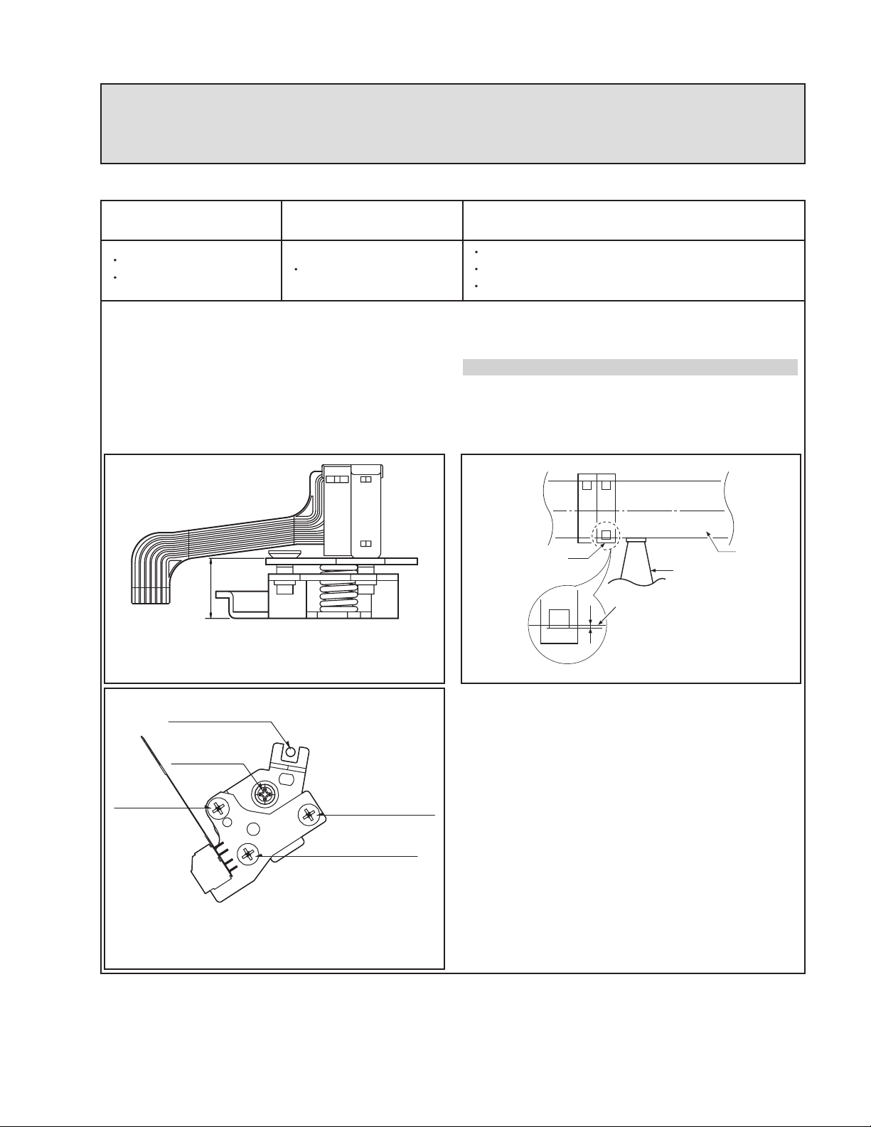
4.3.6 Audio/Control (A/C) Head Adjustment
Purpose of adjustment : To ensure that audio and control signals can be recorded and
played according to the contract tract by constantly maintaining
distance between tape and head, and tape tension between the P3
post and the P4 post.
4.3.6.1 Prior Adjustment (performed only when no audio output appears in play of the standard test tape)
Fixtures and tools used VCR (VCP) status Adjustment position
Blank Tape
Driver (+) Type 5mm
Play the blank tape
Adjustment Procedure/Adjustment Diagrams
1) Basically use the A/C head assembly adjusted as in
SPEC.
2) Check there is crumpling and folding of the tape around
the A/C head. If it is, Turn and adjust the tilt adjusting
screw to ensure that the tape corresponds to the bottom
guide of the P4, and recheck the tape path after proceed ing play for 4-5 seconds.
8.3
A/C Head Base
Tilt adjusting screw (C)
Height adjusting screw (B)
Azimuth adjusting screw (A)
3) Where the tape bottom is not equal to Fig. C-5-3, Adjust
the height by using the height adjusting screw (B) and
then readjust it by using the tilt adjusting screw (C).
CAUTIONS
Always check the height of the A/C head since most ideal
height of A/C head can be obtained when the bottom part
of the tape is away 0.2 ~ 0.25mm from the bottom part of
the A/C head.
A/C Head
P4
Tape
0.2~0.25mm
Tape
Azimuth
Adjustment
Screw(A)
Fig. C-5-1
X-Value Adjustment
Hole
Fixed Screw
A/C Head Assembly
Fig. C-5-2
Fig. C-5-3
Tilt Adjustment
Screw(C)
Height Adjustment
Screw(B)
(No.YD070)1-25
Page 26
4.3.6.2 Tape Path Check between Pinch Roller and Take up Guide (Check in the Rev Mode)
1) Check the tape pass status between the pinch roller and the
take-up guide.(Check there is crumpling of the tape pass and
folding of the take-up guide.)
(1) When holding of the take-up guide bottom occurs
Turn the tilt adjusting screw (C) clockwise and travel it stably to ensure there is no crumbling or folding of the tape.
(2) When holding of the take-up guide top occurs
Turn the tilt adjusting screw (C) anti-clockwise and travel it
stably to ensure there is no crumbling or folding of the tape.
4.3.6.3 Fine Adjustment (Azimuth Adjustment)
2) Check there is folding of the tape at the bottom or top of the
take-up guide in cutting-off the REV mode
CAUTIONS
If the RF waveform is changed after adjusting the A/C head,
perform fine adjustment to ensure the RF waveform is flatened.
Fixtures and tools used Connection position VCR (VCP) status Adjustment position
Oscilloscope
Standard test tape
(only for SP)
Driver (+) Type 4mm
Adjustment Procedure
1) Connect the probe of Oscilloscope to the audio output
jack.
2) Ensure that Audio 1KHz, 7KHz output is flattened at the
maximization point by adjusting the Azimuth adjusting
screw (A).
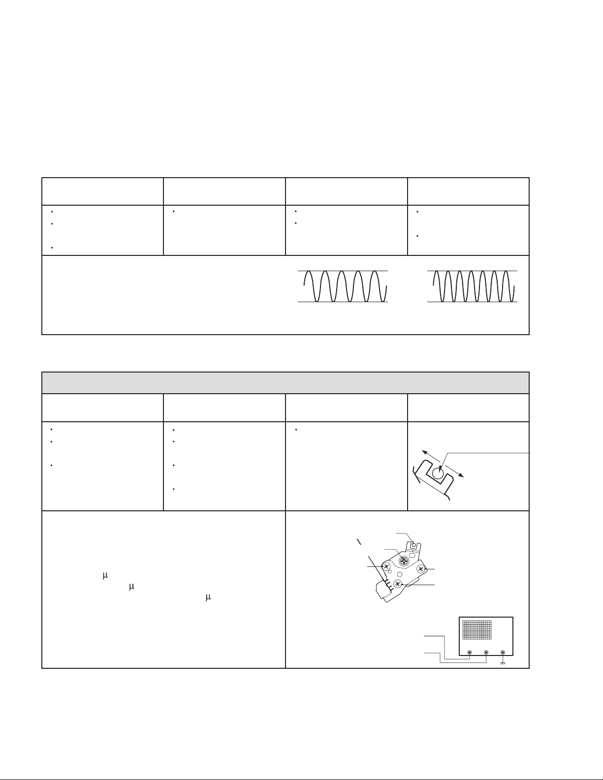
4.3.7 X-Value Adjustment
Audio Output Jack Play the Alignment tape
1KHz, 7KHz.
1KHz
A: Maximum
Fig. C-5-4
Azimuth Adjusting
Screw (A)
Height Adjusting Screw
(B)
B: Minimum
Purpose of adjustment : To maintain compatibility with other VCR (VCP).
Fixtures and tools used Connection position VCR (VCP) status Adjustment position
Oscilloscope
Standard test tape
(only for SP)
Driver (+) Type 4mm
CH-1: PB RF Envelope
CH-2: NTSC ; SW 30Hz
PAL:SW 25Hz
Head switching output
point
RF Envelope output
point
Play the Alignment tape
Left
Grove of Base A/C
Right
7KHz
Adjustment Procedure
1) After releasing the auto tracking, lightly turn the fixing
screw. Turn the (+) type driver on the X-value adjusting
hole to the right or left. Adjust the RF envelope level
to the maximum point and then fix the fixing screws.
2) For the 31 m head, adjust it with the SP tape recorded
in the width of 31 m since the head travels on the tape
track only for SP with the width of 58 m.
1-26 (No.YD070)
Connection Diagram
X-value Adjusting Hole
Fixing Screw
Azimuth
Adjustment
Screw(A)
Fig. C-6
RF ENVELOPE OUTPUT POINT
HEAD RF SWITCHING OUTPUT POINT
Tilt Adjusting Screw (C)
Height Adjusting
Screw (B)
OSCILLOSCOPE
CH-2CH-1
Page 27
4.3.8 Adjustment after Drum Assembly (Video Heads)
Purpose of adjustment : To adjust and stabilize the height change, X-value change, etc
depending on the guide roller after assembling the drum.
Fixtures and tools used Connection position VCR (VCP) status Adjustment position
Oscilloscope
Alignment tape
(only for SP)
Post Height Adjusting
Driver
Driver (+) Type 5mm
CH-1: PB RF Envelope
CH-2: NTSC : SW 30Hz
PAL:SW 25Hz
Head switching output
point
RF Envelope output
point
Checking/Adjustment Procedure
1) Play the blank tape and check whether the guide roller
crumbles or wrinkles the tape and adjust it if necessary.
2) Check that the RF envelope output waveform is flat, and
adjust the height of the guide roller while playing the
alignment tape.
3) Adjust the switching point.
4) Check the RF envelope output is the maximum when
the tracking control locates at the center. If not maximum,
set up to ensure that RF envelope output becomes the
maximum by turning the (+) type driver on the base A/C
groove.
4.3.9 Check of Traveling Device after Deck Assembly
4.3.9.1 Audio, RF Normalization Time (Locking Time) Check in Play after CUE or REV
Play the blank tape.
Play the Alignment tape.
Connection Diagram
RF ENVELOPE OUTPUT POINT
HEAD RF SWITCHING OUTPUT POINT
Waveform
V1/V MAX = 0.7
V1/V MAX = 0.8
RF ENVELOPE OUTPUT
Fine adjustment of
guide roller
Switching Point
Tracking Preset
X-value
OSCILLOSCOPE
CH-2CH-1
V2V1V1
Fixtures and tools used Measuring standard Connection position VCR (VCP) status
Oscilloscope
Alignment tape
(Colour bar)
Stop Watch
RF Locking Time: Within
5 seconds
Audio Locking Time :
Within 10 seconds
CH-1: PB RF Envelope
CH-2: Audio output
RF Envelope output
point
Play the Alignment
tape (Colour bar)
Audio output jack
Checking Procedure
1) Check that locking time of the RF and Audio waveform is
fallen within the measuring standard in conversion of the
play mode from the CUE or the REV mode.
4.3.9.2 Check of Tape Curl and Jam Status
2) Readjust the paragraph 4.3.6 and 4.3.7 if it deviates
from the standard.
Fixtures and tools used Fixtures and tools used Fixtures and tools used
E-240 Tape
E-160 Tape
Checking Procedure
1) Check there is no abnormality of every traveling post
status.
2) There must be no abnormal operation of the counter in
There must be no jam or curl at the
first, middle and end position of tape.
occurrence of folding of the bottom tape. There must be
not abnormality of audio signal in damage of the top tape.
3) If there is abnormality, readjust the adjustment paragraph
4.3.5 and 4.3.6.
Travel the tape at the position
of its first and end.
(No.YD070)1-27
Page 28
4.4 PROTECTION, MAINTENANCE AND CHECK OF VIDEO FUNCTION (VCR)
4.4.1 Checking Points prior to Repair
Following abnormal phenomena may be repaired by removal of
foreign materials and oil supply. Check oiling is required at the
checking set or cleaning status is complete.
Determine that necessity of checking and repair the set exists after checking the using period of the set together with the user. In
this case, followings must be checked:
Phenomena
Color beat Pollution of Full-Erase Head o
S/N, Color Faded Pollution of Video Head o
Horizontal, Vertical Jitte o
Poor Sound, Low Sound o
No tape wound or tape
wound loosely.
FF or REW impossible,
or slow turning
Tape loosely wound in
REV or Unloading
Checking Points and
Cause
Pollution of Video Head or
Tape Transport System
Pollution of Audio/Control
Head
Pollution of Pinch Roller or
Belt Capstan Belt
Deterioration of Clutch
Assembly D37 Torque
Pollution of Drum and
Traveling Device
Replace-
ment
o
o
Fig. C-9-3
CAUTIONS
If operation of the position with (O) mark is abnormal even
after removing cause, replace it with substitute product since
it shows damage or wearing.
F/E Head
Video Head
Fig. C-9-1 TOP VIEW
A/C Head
Pinch Roller
Belt Capston
Clutch
Assembly A37
Fig. C-9-2 BOTTOM VIEW
* No. (1) ~ (12) shows sequence that the tape moves from the supply reel to the take-up reel.)
(3) F/E Head
(5) Drum Assembly
(Video Head)
(4) Base Assembly P2
(2) Tension Post
(1) Supply Reel
Fig. C-9-3 Tape Transport System
1-28 (No.YD070)
(6) Base Assembly
P3
(7) A/C Head
(8) P4 Post
(10) Pinch Roller
(11) Take-up Guide
Post
(9) Capstan Shaft
(12) Take-up Reel
Page 29
4.4.2 Essential Check and Repair
Recording density of the video is far higher than the audio.
Therefore video parts are very precise so as to allow only error
of 1/1000mm or so in order to maintain compatibility with other
videos.
If one of these parts is polluted or old, same phenomena will
appear as they are damaged.
To maintain clear screen, regular check, replacement of old and
damaged parts and oil supply, etc are essential.
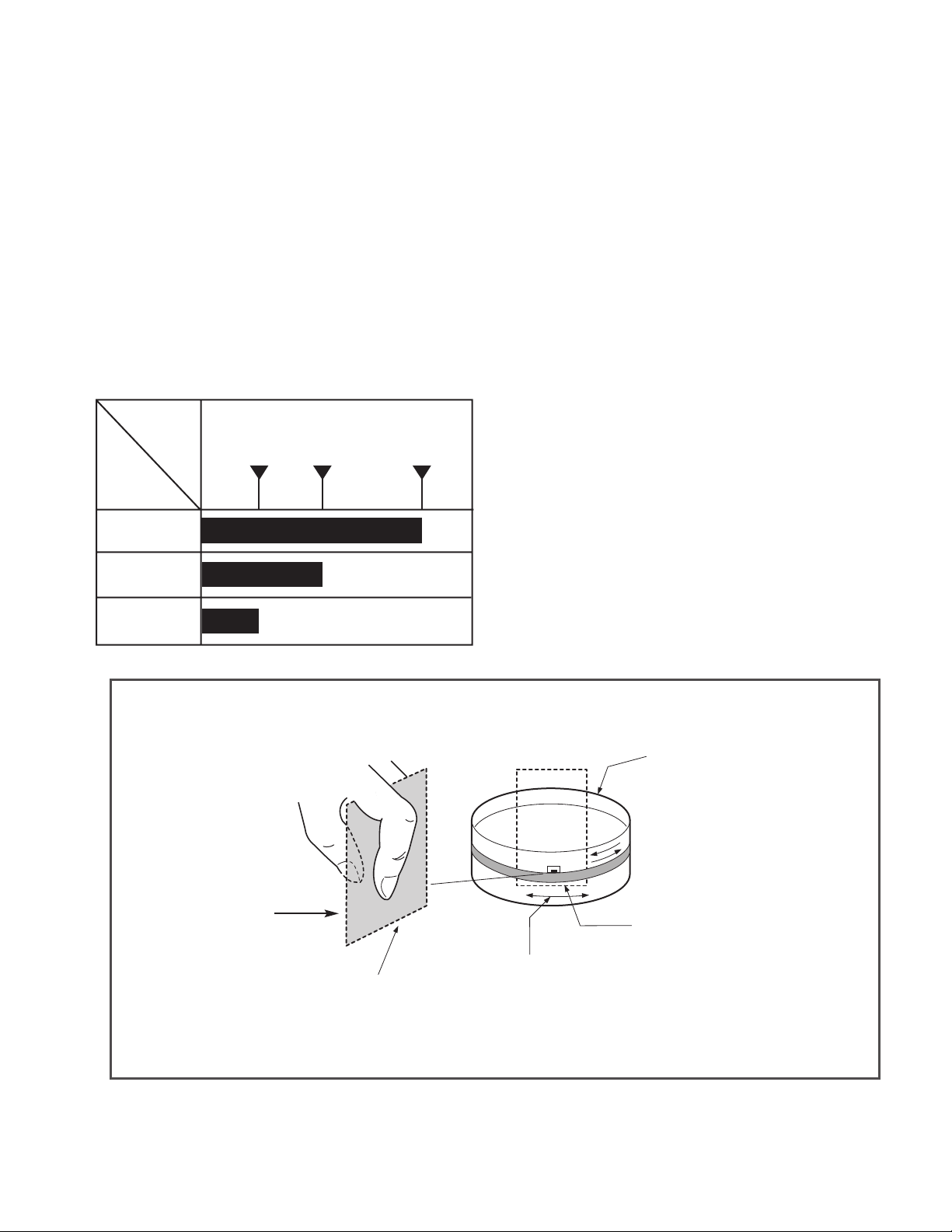
4.4.3 Regular Check and Repair
Check and repair schedule is not constant since they vary depending on method that the consumer uses video and environment where the video is installed at.
However, for the video used by common household, good screen
will be maintained if regular check and repair per 1,000 hour is
performed. The following chart shows relationship between using time and checking time:
Time
Requiring
Checking
Average
hours used
per day
One hour
Two hours
Three hours
About
1 year
About
18 months
About
3 years
4.4.4 Tools for Check and Repair
(1) Grease: Floil G-3114 (KANTO) or equivalent grease
(Green)
(2) Grease: Kanto G-754, PL-433 (Yellow)
(3) Alcohol (Isopropyl Alcohol)
(4) Cleaning Patch (cloth)
4.4.5 Maintenance Process
4.4.5.1 Removal of Foreign Material
(1) Removal of foreign material from video head (Fig. C-9-4)
Firstly try to use a cleaning tape.
Use a cleaning patch if foreign materials are not removed
with the cleaning tape due to severe dirty of the head.
Soak the cleaning patch in alcohol and put it to the head tip.
Smoothly turn the drum (turning cylinder) to the right or left
(In this case, the cleaning patch must not be moved verti-
cally).
After completely drying the head, test the traveling status
of the tape.
If alcohol (Isopropyl Alcohol) remains at the video head, the
tape may be damaged when this solution touches with the
head surface.
Never use a cloth bar (commercial sale)
(2) Wipe the tape transport system and the drive system with
the cleaning patch soaked in alcohol (Isopropyl Alcohol)
when removing foreign materials from them.
1) The part touched with the traveling tape is called as tape
transport system. The drive system consists of parts to
travel the tape.
2) Care must be exercised so that unreasonable force to
change the pattern will be applied to the tape transport
system during removal of foreign materials.
Cleaning Patch
(Cloth)
Soak alcohol
(Isopropyl Alcohol).
Drum
(Turning Cylinder)
Head Tip
Smoothly turn the drum (turning
cylinder) touching the soft surface
to the head tip surface.
Fig. C-9-4
(No.YD070)1-29
Page 30
4.4.5.2 Grease Applications
(1) Grease Application Method
Apply grease by using a cloth swab or brush. Care must be
exercised so that excess quantity should not be used. If the
excessive quantity is applied, wipe it with the gauze soaked
in alcohol (Isopropyl Alcohol).
(1) Inner Side Surface and Top
Surface of Loading Path
(2) Stable Adhesion Part of Base
P2, P3
(3) Arm Pinch Shaft
2
(4) Gear Wheel Shaft
(5) Reel S. T. Shaft
(1) (2) (3) (4): KG-684G
(Green)
(5): PL-433 (Yellow)
(2) Regular Grease Application
Apply grease to the designated application position every
500 hour.
NOTE: POSITION OF GREASE APPLICATION
(1) Inner Side Surface and Top
Surface of Loading Path
(2) Stable Adhesion Part of Base
P2, P3 Coil
(3) Gear Cam Shaft
(4) Gear Drive Shaft
(5) Clutch Shaft Groove
Guide Part on the Plate Slider
(6)
Side Wall (Left)
(7)
Guide Part on the Plate Slider
Side Wall (Right)
(1) (2) (3) (4) (5) (6) (7): KG 684G (Green)
2
Gear Part
1
5
Chassis (TOP)
Cam Part
(PL-433.Yellow)
Gear Part
(PL-433.Yellow)
Gear Sector Gear Cam
Base Loading Gear Drive
Cam Part Side Application
(KG-684G.Green)
Boss Part Side Wall
(PL-433.Yellow)
Gear Part Side Application
(PL-433.Yellow)
4
3
3
4
6
5
7
1
Chassis (Bottom)
Cam Part
(KG-684G , GREEN)
Cam Part
(KG-684G , GREEN)
Gear Rack F/L
1-30 (No.YD070)
Inner Surface of
Guide Rail
(KG-684G.Green)
Chassis (L) Chassis (R)
Lever, Brake Driving Cam Part
Side Wall Guide Part
Lever F/R Driving Part
Plate Slider
Lever Tension Driving Cam Part
Gear Sector Driving Part
Lever, Spring Driving Part
Side Wall Guide Part
Page 31

Lever, F/R, Base, Tension GEAR AY, P2 & P3
LEVER, F/R
Clutch Contact Part
(PL-433, Yellow)
Tension Arm Party
Hinge Part (PL-433, Yellow)
BASE, TENSION
PL-433
(No.YD070)1-31
Page 32

4.5 ELECTRICAL ADJUSTMENT PROCEDURES (VCR)
4.5.1 Servo Adjustment
1) PG Adjustment
Test Equipment
a) OSCILLOSCOPE
b) Alignment tape (SP, stairstep)
Adjustment And Specification
MODE MEASUREMENT POINT ADJUSTMENT POINT SPECIFICATION
PLAY
V.Ou t
H/SW(TP)
R/C TRK JIG KEY 6.5 0.5H
Adjustment Procedure
a) Insert the Alignment Tape and play.
Note - Adjust the distance of X, pressing the Tracking(+) or Tracking(-) when the "ATR" is blink after the
Alignment Tape is inserted.
b) Connect the CH1 of the oscilloscope to the H/SW(TP) and CH2 to the Video Out for the VCR.
c) Trigger the mixed Combo Video Signal of CH2 to the CH1 H/SW(TP) and then check the distance (time
difference), which is from the selected A(B) Head point of the H/SW(TP) signal to the starting point of
the vertical synchronized signal, to 6.5H 0.5H (412 s, 1H=63 s).
PG Adjustment Method
a-1) Playback the Alignment tape
b-2) Press the "OK(ENTER)" key on the Remote controller and the "REC" key on the Front Panel the same
time, then it goes in to Tracking initial mode.
c-3) Repeat the above step(No.b-2), then it finishes the PG adjusting automatically.
d-4) Stop the playback, then it goes out to PG adjusting mode after mony the PG data.
CONNECTION
WAVEFORM
H/SW
(TP)
V.Out
OSCILLOSCOPE
CH1 CH2
R/C KEY
V.outH/SW
(TP)
H/SW
6.5H(412 s)
Composite
VIDEO
1-32 (No.YD070)
Page 33

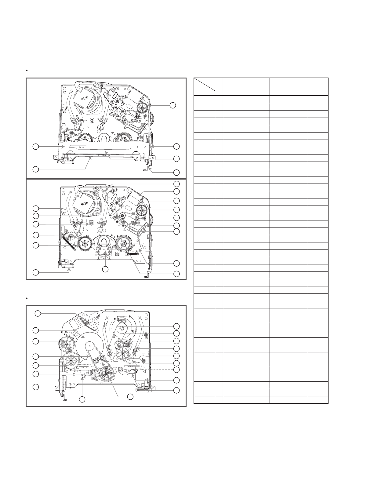
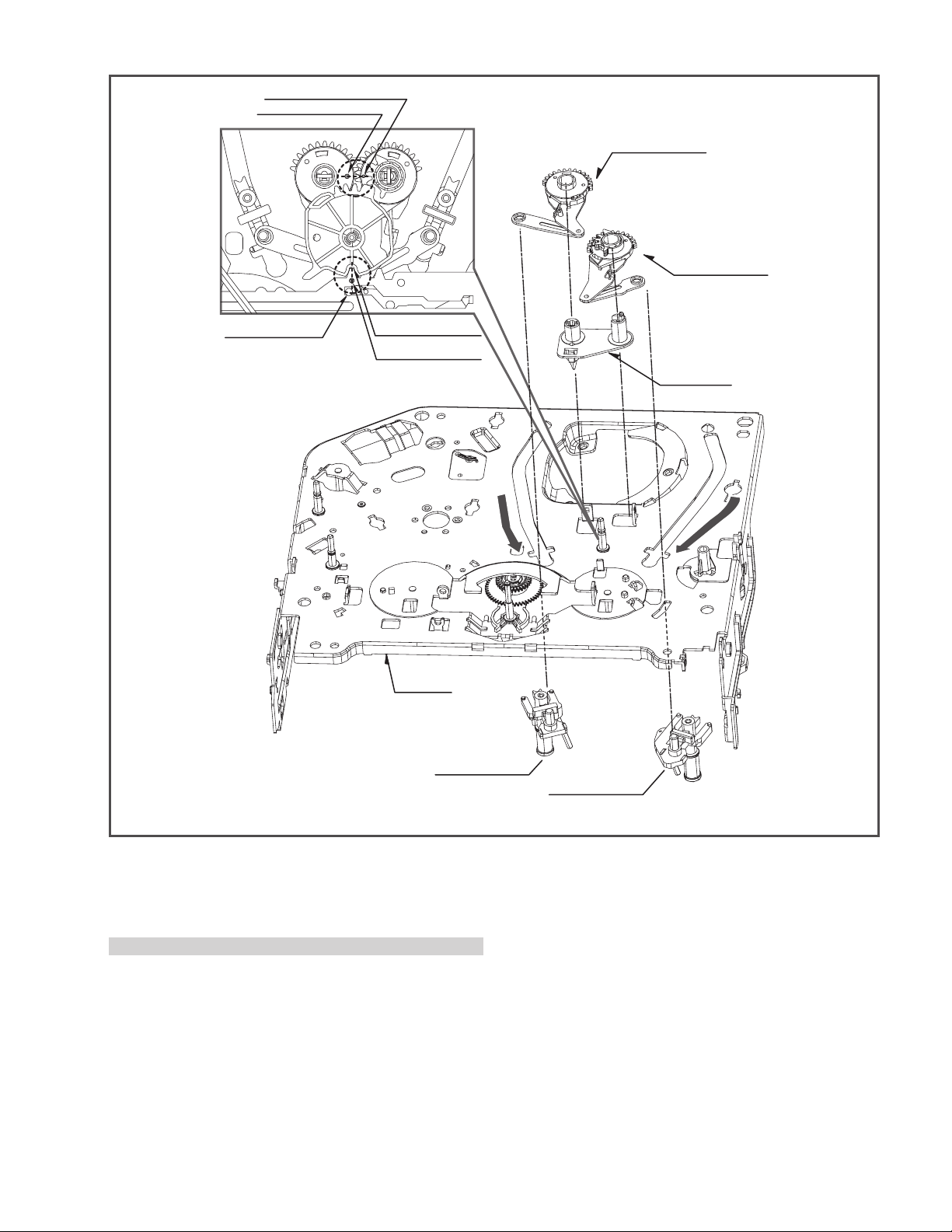
4.6 DECK MECHANISM PARTS LOCATION (DVD)
Top View (With Tray)
Top View (Without Tray)
Procedure
Starting No.
1
Main Base
Clamp Assembly
1
1, 2
1, 2, 3
1, 2, 3, 4
1
1, 6
1, 2, 6
1, 2, 6, 8
1, 2, 6, 8, 9
1, 2, 7
1, 2, 7
1, 2
1, 2 ,13
1, 2, 13, 14
1, 2, 7, 12, 13, 14
1, 2, 13
1, 2, 7, 12, 13,
14, 15, 16, 17
2
Disc
3
Plate Clamp
4
Magnet Clamp
5
Clamp Upper
6
Tray Disc
Base Assembly Sled
7
8
Gear Feed
Gear
9
Middle
10
Gear Rack
11
Rubber Rear
Frame Assembly
12
Up/Down
13
Belt Loading
14
Gear Pulley
15
Gear Loading
16
Guide Up/Down
PWB Assembly
17
Loading
18
Base Main
Parts Fixing Type
4 Screws,
1 Connector
1 Locking Tabs
1 Screw
1 Screw
1 Locking Tab
1 Locking Tab
1 Locking Tab
1 Hook
2Screw
2 Locking Tabs
Disass
embly
Bottom
Bottom
Figure
4-6-1
4-6-1
4-6-1
4-6-1
4-6-1
4-6-2
4-6-3
4-6-3
4-6-3
4-6-3
4-6-3
4-6-4
4-6-4
4-6-4
4-6-4
4-6-4
4-6-4
4-6-4
Bottom View
Note
When reassembling, perform the procedure in
reverse order.
The "Bottom" on Disassembly column of above
Table indicates the part should be disassembled
at the Bottom side.
(No.YD070)1-33
Page 34

PLATE CLAMP
MAGNET CLAMP
CLAMP UPPER
MAIN BASE
DISC CLAMP ASSEMBLY
TRAY DISC
HOLDER
(Fig. A)
BASE MAIN
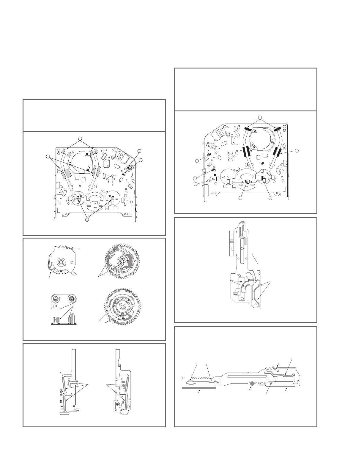
1.Main Base (Fig. 4-6-1)
1-1. Clamp Assembly Disc
1) Place the Clamp Assembly Disc as Fig. (A)
2) Lift up the Clamp Assembly Disc in direction of
arrow(A).
3) Separate the Clamp Assembly Disc from the Holder
Clamp.
1-1-1. Plate Clamp
1) Turn the Plate Clamp to counterclockwise direction
and then lift up the Plate Clamp.
1-1-2. Magnet Clamp
1-1-3.Clamp Upper
BASE MAIN
LEVER
BASE MAIN
BOTTOM SIDE VIEW
Fig. 4-6-2Fig. 4-6-1
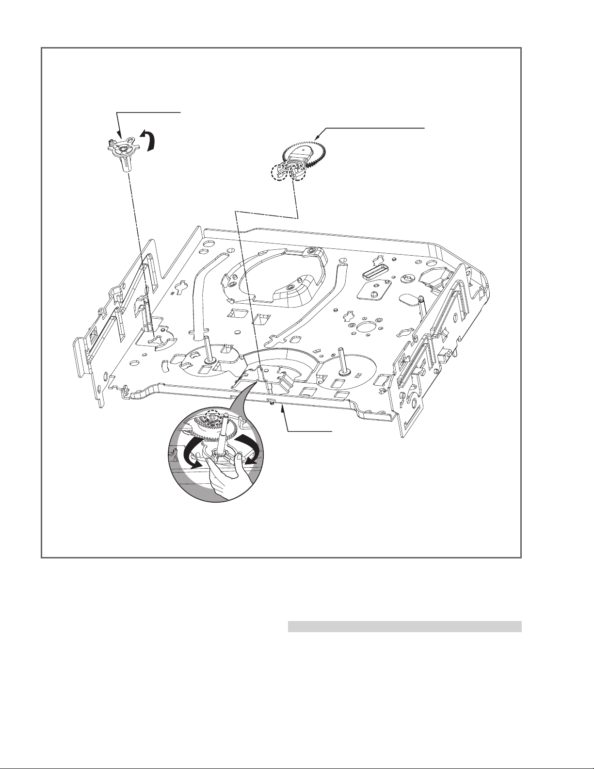
2. Tray Disc (Fig. 4-6-2)
1) Insert and push a Driver in the emergency eject
hole(A) at the right side, or put the Driver on the
Lever(B) of the Gear Emergency and pull the Lever(B)
in direction of arrow so that the Tray Disc is ejected
about 15~20mm.
2) Pull the Tray Disc until it is separated from the Base
Main completely.
1-34 (No.YD070)
Page 35

GEAR RACK
RUBBER DAMPER
(S3)
PINION GEAR
MIDDLE GEAR
SCREW INSERTION TORGUE CONTROL
(800gf DOWN)
RUBBER DAMPER
Distinguish upper and
lower sides
(Assemble with care)
RUBBER DAMPER
Distinguish upper and
lower sides
(Assemble with care)
BASE PU
GEAR RACK
SPINDLE MOTOR ASSEMBLY
3.Base Assembly Sled (Fig. 4-6-3)
1) Release 4 Screw(S2).
2) Disconnect the FFC Connector(C1)
3-1. Gear Feed
3-2. Gear Middle
RUBBER DAMPER
GENERAL PICK UP ASSEMBLY
Fig. 4-6-3
(S2)
3-3. Gear Rack
1) Release the Scerw(S3)
4. Rubber Rear (Fig. 4-6-3)
(S2)
(No.YD070)1-35
Page 36

GUIDE UP/DOWN
GEAR PULLEY
SCREW INSERTION
TORGUE CONTROL
(800gf DOWN)
GUIDE UP/DOWN
GEAR LOADING
(L4)
BELT LOADING
BASE MAIN
(A)
(L5)
FIG. (A)
(B)
PWB ASSEMBLY LOADING
(A)
(B)
(C)
(C2)
(S5)
(A)
(B)
GUIDE UP/DOWN
(L3)
(L6)
(L6)
BASE MAIN
(H1)
(S4)
UP/DOWN FRAME ASSEMBLY
FIG. (B)
GUIDE UP/DOWN
FIG. (C)
5. Frame Assembly Up/Down (Fig. 4-6-4)
Note
Put the Base Main face down(Bottom Side)
1) Release the screw(S4)
2) Unlock the Locking Tab(L3) in direction of arrow and
then lift up the Frame Assembly Up/Down to separate
it from the Base Main.
Note
When reassembling move the Guide Up/Down in direction
of arrow(C) until it is positioned as Fig.(C).
When reassembling insert (A) portion of the Frame Assembly Up/Down in the (B) portion of the Guide Up/Down
as Fig.(B)
6. Belt Loading(Fig. 4-6-4)
Note
Put the Base Main on original position(Top Side)
7. Gear pulley (Fig. 4-6-4)
1) Unlock the Locking Tab(L4) in direction of arrow(B) and
then separate the Gear Pulley from the Base Main.
Fig. 4-6-4
8. Gear Loading (Fig. 4-6-4)
9. Guide Up/Down (Fig. 4-6-4)
1) Move the Guide Up/Down in direction of arrow(A) as
Fig.(A)
2) Push the Locking Tab(L5) down and then lift up the
Guide Up/Down to separate it from the Base Main.
Note
When reassembling place the Guide Up/Down as Fig.(C)
and move it in direction arrow(B) until it is locked by the
Locking Tab(L5). And confirm the Guide Up/Down as Fig.(A)
10. PWB Assembly Loading (Fig. 4-6-4)
Note
Put the Base Main face down(Bottom Side)
1) Release 1 Screws(S5)
2) Unlock the Loading Motor (C2) from the Hook (H1) on
the Base Main.
3) Unlock 2 Locking Tabs(L6) and separate the PWB
Assembly Loading from the Base Main.
11. Base Main(Fig. 4-6-4)
1-36 (No.YD070)
Page 37

SECTION 5
TROUBLESHOOTING
5.1 ELECTRICAL TROUBLESHOOTING GUIDE (VCR PART)
5.1.1 Power(SMPS) CIRCUIT
(1) No 5.3VA
No 5.3VA
YES
Is the FR101
Normal?
YES
Is the BD101
Normal?
YES
Is the R101
Normal?
YES
Is Vcc (9V - 18V) supplied to IC101 Pin2?
YES
Are the D125
normal?
Is there about 2.5V
at the IC103 Pin1?
YES
NO
NO
NO
NO
NO
NO
Replace the FR101
(Use the same ICW)
Replace the
BD101
Replace the R101
Is the D102
normal?
Replace the R125
Replace the IC103
Check or Replace
the D102
Is the D123
normal?
YES
Is the D124
Normal?
YES
Is the D121
Normal?
YES
Power Line of Main
PCB is short
NO
NO
NO
Replace the D123
Replace the D124
Replace the D121
(No.YD070)1-37
Page 38

(2) No 5.0V_D
(3) No 5.0V_T
No 5.0V_D
YES
Is the Vcc(5.3V) supplied to Q165 Emittor?
YES
Is the Q162 Base
'H'?
YES
Check or Replace
the Q165
(4) No 3.3V
No 3.3V
YES
NO
NO
Check or Replace
the D125
Check the PWR CTL
"H" signal from -com
No 5.0V_T
YES
Is the Vcc(5.3V) supplied to Q163 Emittor?
YES
Is the Q162 Base
'H'?
YES
Check or Replace
the Q163
(5) No 33V
No 33V
YES
NO
NO
Check or Replace
the D125
Check the PWR CTL
"H" signal from -com
Is there about 3.8V
at the IC131 pin1?
YES
Is there about 3.3V~5V
at the IC131 pin4?
YES
Check the IC131
and Replace
NO
NO
Check or Replace
the D123
Check the PWR CTL
"H" signal from -com
Is the Vcc(33V) supplied to Q161 Emittor?
YES
Is the Q162 Base
'H'?
YES
Check or Replace
the Q161
NO
NO
Check or Replace
the D121
Check the PWR CTL
"H" signal from -com
1-38 (No.YD070)
Page 39

(6) No Motor_Vcc (To Cap, Drum Motor )
(7) No REG 12V
No Motor_Vcc
YES
Is the Vcc(14V)
supplied to C134?
YES
Check or Replace
the Cap / Drum
NO
Check or Replace
the D124
No REG 12V
YES
Is the Vcc(14V) supplied
NO
to Q165 Collector?
YES
Is the Vcc(14V) sup-
NO
plied to Q165 Base?
YES
Check or Replace
the Q165
Check or Replace
the D124
Check the PWR CTL
"H" signal from -com
(No.YD070)1-39
Page 40

5.1.2 SYSTEM/KEY CIRCUIT
(1) AUTO STOP
Auto Stop
YES
Does the SW25 waveform
appear at the IC501
Pin23?
NO
Check the Drum Motor
signal.
YES
Do the T-UP Reel Pulses
NO NO
appear at the IC501 Pin3?
YES
Replace the IC501. Check the Power Circuit.
Do T/UP Reel Pulses
appear at the Q514 Base
terminal?
YES YES
Replace the T/UP Reel
Sensor (RS501).
Does 5.0V appear at the
RS501?
(2) The unstable loading of a Cassette tape
The unstable loading of a
Cassette tape
YES
Is 12V applied to the
PMC01 Pin8?
NO
Check the Power.
NO
YES
Does the "H" signal appear
at the IC501 Pin32 during
NO
inserting the CST ?
YES YES
Does the "L" signal appear
at the IC501 Pin19 during
inserting the CST?
YES
NO
Check the CST SW and
the peripheral circuitry.
Check the Deck
Mechanism.
Caution : Auto stop can occur because Grease or Oil is dried up
Is 5.0V applied to the
R544 ?
NO
Refer to SMPS 5.3VA
troubleshooting.
Check the IC501
Pins 86, 87, 88, 89.
1-40 (No.YD070)
Page 41

5.1.3 SERVO CIRCUIT
(1) Unstable Video in PB MODE
Unstable Video in
PB Mode.
YES
Does the Noise level of the
screen change
periodically?
YES
Does the CFG waveform
appear at the IC501
Pin67?
YES
On tracking do the CTL
pulses move?
YES
Does the Video Envelope
waveform appear at the
IC501 Pin82?
YES
Replace the IC501.
(2) When the Drum Motor
doesn't run.
When the Drum Motor
doesn't run,
YES
Does 12V appear at the
PMC01 Pin8?
YES
Does 2.8V appear at the
PMC01 Pin12?
YES
Check the connector
(PMC01) and the Drum
Motor Ass'y.
NO
NO
NO
NO
Replace the IC501.
Refer to "When the Y signal
doesn't appear on the
screen in PB Mode".
Refer to "(2)
No 12VA of Power section"
Do the Drum PWM Pulses
appear at the IC501
Pin34?
YES
Aren't the foil patterns and
the Components between
IC501 Pin34 and PMC01
Pin12 short?
YES
Do the DFG Pulses appear
at the IC501 Pin104?
YES
Do the Drum PWM Pulses
appear at the IC501
Pin34?
NO
NO
NO
Do the DFG Pulses appear
at the PMC01 Pin11?
YES
NO
Replace the Cap M.
Aren't the foil patterns and
the Components between
IC501 Pin 104 and PMC01
Pin11 short?
Replace the IC501.
Aren't the connecting patterns and the Components
between IC501 Pin34 and PMC01 Pin12 short?
(No.YD070)1-41
Page 42

(3) When the Capstan Motor doesn't run,
When the Capstan Motor doesn't run,
Does 12VA appear at the PMC01?
YES
Does 2.8V appear at the PMC01?
YES
Check the PMC01 and the Capstan
Motor Ass'y.
Aren't the foil patterns and Components
between IC501 Pin33 and PMC01
Pin9 short?
Does the CFG signal come into the
IC501 Pin67?
NO
NO
YES
YES
Refer to "SMPS(CAPSTAN/12Volt)
Trouble Shooting".
Does the PWM signal appear at the
IC501 Pin33?
NO
Does the CFG signal appear at the
PMC01 Pin1?
NO
Check the Capstan Motor Ass'y.
YES
Does the Capstan PWM signal appear at
the IC501 Pin33?
YES
Aren't the foil patterns and Components
between IC501 Pin33 and PMC01
Pin9 short?
(4) KEY doesn't working
KEY doesn't working.
Is 5V applied to the IC501
NO
Pin36?
YES
Does LED or FLD change
when a function button is
NO
pressed?
NO
Aren't the foil patterns and component
between IC501 Pin67 and PMC01
Pin1 short?
NO
Replace the IC501.
Refer to "SMPS 5.3VA
Trouble Shooting".
Replace the defective
switches.
1-42 (No.YD070)
Page 43

5.1.4 Y/C CIRCUIT
(1) No Video in EE Mode,
No Video in EE Mode
Does the Video signal
appear at the IC301 Pin48?
YES
Is 5V applied to the IC301
Pins18, 24, 42, 55, 72, 91?
YES
Does the Video signal
appear at the IC301 Pin65?
YES
Does the Video signal
appear at the IC501 Pin47?
YES
Does the Video signal appear
at the Emitter terminal of the
Q309?
NO
NO
Check the 19Pin of Tuner.
Check the 5.0VT, 5.3VA
Line. (Power Circuit)
NO NO
Is I2C BUS signal applied to
the IC301 Pins68, 69?
YES
NO
Chck the path of the signal
between the IC301 Pin65
and IC501 Pin49.
NO
Does the 12VT, 5.3VA
appear at the Emitter
NO
terminal of the Q309.
YES
Check the System Circuit.
(Refer to 'SYSTEM I
2
C BUS
CHECK Trouble Shooting')
Check C316. (AGC)
YES
Replace the IC301.
Replace the Q309.
Check the 12VT, 5.4VA
Line. (Power Circuit)
(No.YD070)1-43
Page 44

(2) When the Y(Luminance) signal doesn't appear on the screen in PB Mode,
Is 5.0VT, 5.3VA applied to the
IC301 Pins24, 42, 55, 72, 91?
YES
Is the I
2
C Bus siganl applied
to the IC301 Pins68, 69 ?
YES
Does the normal RF signal
appear at the IC301 Pin78?
YES
NO
Check the line of the 5.0VT,
5.3VA Line. (Power Circuit)
NO
Refer to 'SYSTEM I2C BUS
CHECK Trouble Shooting'.
NO NO
Is the V.H.S/W signal
applied to the IC301 Pin70?
YES
Is V.H.S/W "H" about 3.4V
NO
at the IC301 Pin70?
YES
Clean the Drum.
NO
Check the System Circuit.
(IC501 Pin23)
Check the V.H.S/W level.
(Check R303, R304)
Replace the IC301.
Does the Y(Luminance) RF
signal appear at the IC301
Pin79?
YES
Is the Y(Luminance) Video
waveform showed up at
theIC301 Pin43?
YES
Replace the IC301.
NO
NO
Check the path of the
Y(Luminance) RF signal.
(Check the C312)
Check the path of the
Y(Luminance) RF signal.
(Check C327)
YES
YES
1-44 (No.YD070)
Page 45

(3) When the C(Color) signal doesn't appear on the screen in PB Mode,
Is 5.0VT/5.3VA applied to the
IC301 Pins24, 42, 55, 72, 91.
YES
Is the Color Rotary signal
applied to the IC301
Pin70?
YES
Is Color Rotary "H"
about 3.4V?
YES
Does the Color signal
appear at the IC301
Pin25 ?
YES
NO
Check the line of the 5.0VT/
5.3VA Line. (Power Circuit)
NO
Check the Color Rotary
Circuit. (IC501 Pin98 )
NO
Check the Color Rotary
level. (Check the R303)
NO NO
Does the X301(4.43MHZ)
oscillate?
Does the Color signal
NO
appear at the IC301 Pin21?
Replace the X301.
Check the Color Pass.
YES
Replace the IC301.Replace the IC301.
(No.YD070)1-45
Page 46

(4) When the Video signal doesn't appear on the screen in REC Mode,
Is the EE signal normal?
YES
Is 5.0VT/5.3VA applied to the
IC301 Pins24,42,55,72,91?
YES
Does PB Mode operate
normally?
YES
Does the RF signal appear
at the IC301 Pin78?
YES
NO
NO
NO
NO
Check EE Mode.
Check the line of the 5.0VT/
5.3VA Line.(Power Circuit)
Check PB Mode.
Is the REC 'H' signal
(about 4V) applied to the
IC301 Pin80?
YES
Check REC Luminance
Pass & Color Pass.
NO
YES
Check the System of REC
'H'. (the IC501 Pin27
/ the D301)
Replace the IC301.
Does the REC RF signal
appear at the IC301
Pins88,89,94,95?
YES
Check the Drum &
Drum Connector
NO
Check the circuit of the
IC301 Pins85, 86.
YES
1-46 (No.YD070)
Page 47

5.1.5 Hi-Fi CIRCUIT
(A) No Sound(EE Mode)
YES
No Sound.
Check the TU Audio of IC801
Pins2, 3.
Check the DVD Audio of IC801
Pins4, 5.
Check the AV1 Audio of IC801
Pins6, 7.
Check the AV2 Audio of IC801
Pins8, 9.
Check the AV3 Audio of IC801
Pins10, 11.
Check the Vcc of IC801 Pins34, 40,
IC802 Pin13.
NO
NO
NO
NO
NO
YES
NO
Check the IC751 Pins30, 31.
Check the DVD Audio OUT.
(JK902 DVD_A_L_L/R).
Check the Scart1 Jack.
(SC901 Scart1 Audio in Pins2, 6).
Check the Scart2 Jack.
(SC901 Scart2 Audio in Pins2, 6).
Check the front Jack.
Check the Power 5.0V, 12VT.
YES
Check the IIC Clock and DATA at
IC801 Pins42, 43.
YES
YES
YES
Check the JK902, SC901.
NO
NO
NO
Check the IC501 Pins17, 18.
Replace IC801.Check the Audio of IC801 Pins16, 17.
Replace IC802.Check the Audio of IC802 Pins1, 14.
(No.YD070)1-47
Page 48

(B) Hi-Fi Playback
PB mode
No Sound.
YES
YES
Check the Vcc of IC801
NO
(Pins34, 40)
YES
Check the Hi-Fi Selection switch.
NO
(IC801 Pin41) and the Tape quality.
YES
Is the RF Envelope at
NO
IC801 Pin44 over 2Vp-p?
YES
Check IC801 Pin42(Data),
NO
Pin43(Clock)
YES
Do Audio Signals appear at
NO
IC801 Pin16(L-CH), 17(R-CH)?
YES
Do Audio Signals appear at
NO
IC802 Pin10(L-CH), 16(R-CH)?
YES
Check Power 5.0V, 12VT.
Check IC501 Pin26
(A.H/SW)
Check the parts of -COM
(IC501 Pins17, 18)
Check the Connection at
P3D01 Pins7, 9.
Check the A.IN line of
IC802(C850, C852)
Do Audio Signals appear at
IC802 Pins11, 16?
Do Audio Signals appear at
JK902?
1-48 (No.YD070)
NO NO
Check the Vcc of IC802
Pin13.
YES YES
Replace IC802.
NO
Check the Jack(JK902)
Check Power.
Page 49

(C)
Hi-Fi REC.
It can't be recorded Hi-Fi Audio
signal.
YES
YES
Check Vcc of IC801.(Pins34, 40)
YES
Check IC801 Pin42(Data), Pin43(CLOCK).
YES
Do Audio signals appear at IC801
Pins16, 17?
YES
Do FM Audio signals appear at IC801
Pin36?
YES
Check the Contact Point of Drum
Connector if good then Replace the Drum.
NO
NO
NO
NO
Check Power 5V, 12V.
Check ports of -COM.
(IC501 pins 17, 18)
Check Audio input signal of IC801
Pins2, 3(TU.A.), 4, 5(DVD.A.),
6, 7(AVI.A.), 8, 9(AV2.A.), 10, 11(AV3.A.).
Replace IC801.
(No.YD070)1-49
Page 50

5.1.6 Tuner/IF CIRCUIT
(A) No Picture on the TV screen
No picture on the TV
screen
YES
Does the Video signal at
the TU701 Pin19.
YES
Is 33VT applied to TU701
Pin17?
YES
Is 5VT applied to TU701
Pin4?
YES
Does the Clock signal
appear at TU701 Pin12?
YES
Does the data signal
appear at TU701 Pin13?
YES
Replace Tuner.
NONO
NO
NO
NO
Check 33V line.
Check 5V line.
Check the lIC Clock Signal
of -COM Pin18.
Check the lIC Data Signal
of -COM Pin17.
Does Sync appear at
NO
IC501 Pin111.
YES
Does the Video signal at
NO
the IC501 Pin47.
YES
Does the Video signal at
NO
the IC301 Pin61.
YES
Does the Video signal at
NO
the IC903 Pin6.
YES
Check the signal flow from IC903
Pins26, 27 to SC901 Pin19.
Check the signal flow from
TU701 Pin19 to IC301 Pin48.
Check the signal from IC301
Pin65 to IC501 Pin49.
Check the signal from IC501
Pin47 to IC301 Pin56.
Check the signal from IC903
Pin6 to IC301 Pin61.
1-50 (No.YD070)
Page 51

(B) No Sound
No Sound.
YES
Check the Vcc of IC751 Pins1, 11, 19,
22, 33.
YES
Check the Tuner SiF signal at IC751
Pin2.
YES
Check the oscillator of IC751 Pins5, 6.
YES
Check the Audio of IC751 Pins30, 31.
YES
Check the Audio of IC801 Pins2, 3.
YES
NO
NO
NO
NO
NO
Check 5.0V Line.
Check the Tuner SIF of TU701 Pin22.
Replace X751
Check the IIC Clock and Data at IC751
Pins12, 13.
Check the signal flow from IC751
Pins30, 31 to IC801 Pins2, 3.
Check the Audio of IC801 Pins16, 17.
YES
Check the Audio of IC802 Pins3, 5.
YES
Check the Signal flow from IC802
Pins3, 5, SC901 Pins1, 3.
NO
NO
Check the IIC Clock and Data at IC801
Pins42, 43.
Check the signal flow from IC801
Pins16, 17 to IC802 Pins11, 16.
(No.YD070)1-51
Page 52

5.2 MECHANISM TROUBLESHOOTING GUIDE (VCR PART)
5.2.1 Deck Mechanism
A.
No Auto Rewind operates.
YES
Is output of the end sensor “H”?
“H”: 3.5V or less
“L”: 0.7V –1V or less
NO
YES
Is voltage at both ends of the
IR LED 0.8V-1.5?
YES
Is the Syscon checked?
B.
No F/R operates.
YES
Is the current mode an F/R
mode?
NO
NO
Is the end sensor Vcc applied at
5V?
YES
Replace the end sensor.
Replace the LED.
Check the assembly position of
the Mode S/W.
NO
Check the Syscon power supply.
YES
Does the Capstan motor rotate?
YES
Does the T/up and the supply
reel Operate?
YES
Check the Syscon circuit.
1-52 (No.YD070)
NO
Is normal voltage applied at the
Vcc1 and the Vcc2 of the
Capstan motor?
YES
Is the Vctl terminal voltage of the
Capstan Motor applied at more
than 4V?
YES
Replace the Capstan motor.
NO
Check the Servo, Power
circuit.
Page 53

C.
Auto Stop operates.
(PLAY/CUE/REV)
Check the assembly mode.
Check the spring pinch.
Does the pinch roller attached to
the Capstan shaft turn in operation of the Play/Cue/Rev.
YES
Does the T/UP or the supply
reel pulse occur?
YES
Check the Syscon, -com.
D.
No cassette loading is done.
Insert the cassette.
NO
NO
Is output of the DFG, DPG
normal?
YES
Check the Servo, Syscon.
Replace the reel sensor.
NO
Replace the drum motor.
YES
Is operation of the lever
assembly S/W normal?
YES
Does output of the CST IN S/W
change?
(In insertion of the REC tape:
"L"_"H"_"L")
(In insertion of the REC prevention tape:
"L"_"H"_"L"_"H")
YES
Check the Syscon circuit.
NO
NO
NO
Check the holder assembly CST.
Is the CST IN S/W normal?
YES
Check the Syscon circuit.
NO
Replace the CST IN S/W.
(No.YD070)1-53
Page 54

E.
No tape winding is done in
play.
Is the pinch roller attached to the
Capstan shaft in operation of play?
YES
Does the T/up reel operate?
YES
Does the Capstan motor turn?
YES
Does the drum motor turn?
YES
Is the DPG, DFG normal?
NO
NO
NO
Check the assembly mode?
Is the Capstan belt hung?
YES
Check the clutch and the idler
assembly.
Is normal voltage applied to the
capstan motor Vcc1, Vcc2?
YES
Is the Vctl terminal voltage of
the Capstan motor applied at
more than 4V?
NO
Hang the Capstan belt.
NO
Check the Servo, power circuit.
YES
Are the T/up and the reel sensor
normal?
YES
Check the Syscon circuit.
NO
YES
Replace the Capstan motor.
Is the Vcc voltage of the drum
motor normal?
YES
Is the Vctl terminal voltage of the
drum motor at more than 2.3V?
YES
Replace the drum motor.
NO
Check the Syscon circuit.
NO
Check the Syscon circuit.
1-54 (No.YD070)
Page 55

5.2.2 Front Loading Mechanism
A.
No cassette insert is done.
Does the lever assembly
switch operate?
YES
Is the Vcc of the main P.C.B
assembly?
YES
Is voltage between the cassette
switch terminal and the GND on
the main P.C.B assembly?
YES
Check the mode switch position
and the Syscon circuit.
NO
NO
NO
Is the lever assembly switch
spring normal?
NO
Add or replace the lever
assembly switches spring.
YES
Does the CST IN switch
operate normally?
NO
Replace the F/L switch.
YES
Check the Syscon circuit.
Check the power circuit.
Is there short between the cassette switch terminal
and the GND on the main P.C.B assembly?
YES
Replace the main P.C.B assembly or remove the short part.
NO
Replace the CST IN switch.
B.
No cassette eject is done.
Does the L/D motor turn in reverse?
YES
Does the lever assembly switch operate?
YES
Does the arm assembly F/G operate?
YES
Does the opener door operate?
NO
Check the L/D motor and the drive IC.
NO
Replace the lever assembly switch.
NO
Replace the arm assembly F/L
NO
Replace the opener door.
(No.YD070)1-55
Page 56

C.
No safe adherence of tape is done.
Is cassette insert done?
YES
Does the opener lid operate?
YES
Does the gear rack F/L operate?
NO
NO
YES
Does the opener door operate?
YES
Does the arm assembly F/L operate?
YES
Does the L/D motor operate?
NO
NO
Replace the opener lid.
Replace the gear rack F/L.
Check the assembly status of the
opener door.
Replace the arm assembly F/L.
YES
Does the holder assembly cassette move
same as the arm assembly F/L?
YES
Replace the front loading mechanism
assembly.
1-56 (No.YD070)
NO
Check power supply of the L/D motor.
NO
Check the assembly status of the
holder assembly cassette.
Page 57

5.3 ELECTRICAL TROUBLESHOOTING GUIDE (DVD PART)
5.3.1 System operation flow
Power On
1. 8032 initializes SERVO, DSP & RISC registers
2. Write RISC code to SDRAM
3. Reset RISC
Show LOGO
Yes
Tray Close to Closed position
SLED Moves to Inner Position
1. Judge whether have disc and disc type
2. Jump to related disc reading procedure
Tray Closed?
No
SLED at Inner
Side?
No
Recieve
OPEN/ CLOSE
Key?
Yes
No
1. Execute Pressed Key & IR Key
2. Systemoperati on Routi ne Loop
1. Stop Playback & Open Tray
2. Display tray open message & LOGO
No
Receive
CLOSE Key?
Yes
(No.YD070)1-57
Page 58

5.3.2 SYSTEM Test flow
TEST
Check the AC Voltage
Power PCBA(110V or 220V)
YES
Switch on the Power PCBA
Is the DC Voltage
outputs OK?
(5V,1.8V,3.3V,8V,12V)
YES
Make sure the main PCBA don't
short on VCCs and switch it on.
NO
NO
Replace power PCBA or
AC transformer.
Repair or Replace Power PCBA
Is 3.3V and 1.8V DC
outputs normal on main
PCBA?
YES
Connect to PC CN601 Cable and
update the FLASH memory code.
Update FLASH
successfully?
YES
A
NO
NO
Check the regulators or related diodes.
1. Check 27MHz system clock.
2. Check system reset circuit.
3. Check FLASH R/W enable signal PRD,RWR.
4. Check CN601 SIGNALS.
5. Check FLASH Memory related circuit.
1-58 (No.YD070)
Page 59

A
RESET or Power On.
Show LOGO?
YES
NO
Flash Memory operates
properly?
YES
SDRAM works properly?
YES
ZR36868 VIDEO outputs
properly?
YES
Have TV signal output?
YES
Check AV cable connection
to TV set.
NO
NO
NO
NO
Check connection lines between FLASH
& ZR36868 and the FLASH access time
whether is suitable or not.
Check connection lines between SDRAM
& ZR36868 and the SDRAM is damaged.
Check the related circuit of ZR36868
Check the filtering and amp circuit of
TV signal.
Does Tray move
inside when it is not
at closed position?
YES
B
NO NO
Normal TROUT &TRIN
signals?
YES
Normal TRCLOSE &
TROPEN signal?
YES
Normal LOAD+ & LOAD-
signal?
YES
Check the cable connection between
main PCBA and loader.
NO
NO
Check the load OPEN & CLOSE switch
Check the Tray control IO pins on
MT1389 & BA5954
Check the Tray control amplifying
circuit on Motor driver.
(No.YD070)1-59
Page 60

B
Does
the SLED move
to inner side when it is at
outter position?
NO NO
Motor Driver STBY
Pin is High?
Check the connection line of
STBY signal.
YES
Do not put in disc and tray close.
YES
Is FMSO
DC Level higher
than 1.4V?
YES
SL+ and
SL- outpup
properly?
YES
Check the cable connection with
MECHA.
NO
NO
Check the related circuit of
FMSO.
Check the amp circuit on motor
driver.
Optical Lens has
movements for searching
Focus?
YES
C
NO NO
Check cable connect on with
pick-up head.
Proper
FOSO outputs
to motor driver?
YES
Proper F+ & F-
outputs?
YES
NO
Check FOSO connection on
MT1389 and motor dirver.
Check the amp circuit on motor
dirver.
1-60 (No.YD070)
Page 61

C
Laser turns on when
reading disc?
YES
Put disc in? Laser off
YES
Disc ID is correct?
YES
NO NO
NO
NO
LD01 or LD02 output
Collector voltage of
power transistor is OK?
Check cable connection between
transistor ouput and pick-up head.
signal on MT1389?
properly?
YES
YES
Proper RFL
YES
NO
NO
Check the laser power circuit
on MT1336 and connecting to
power transistor.
Check the related circuit on
laser power transistor
Check the related circuit
on MT1389 RFL signal
Does spindle rotate?
YES
D
Check LD01 & LD02 signal
NO NO
Check the cable connection
between spindle and main PCBA.
Proper
DMS0 signal on
MT1389
YES
SP+ & SP- output
properly?
YES
NO
Check DMS0 related
ci
rcuit on MT1389
Check the spindle control
amp circuit of motor driver.
(No.YD070)1-61
Page 62

D
YES
Focus ON OK?
YES
Track On OK?
YES
NO
NO
Proper signals on
A,B,C,D of MT1389
YES
Check FEO signal
on MT1389
YES
Check FOSO signal on MT1389
Normal TEO Signal on
MT1389?
YES
Properly TRSO signal
on MT1389?
YES
NO
NO
NO
NO
Check connections between
MT1389 and pick-up head.
Check the FOSO connection on
MT1389 and motor driver.
Check the related
circuit on MT1389
Check the TRSO
connection on MT1389
and motor dirver.
Disc is play ?
YES
E
NO
T+ & T- output
properly?
YES
Check cable connection on
pick-up head.
Check RFO & RFLVL signal waveform.
NO
Check the tracking control
amp circuit on motor
driver.
1-62 (No.YD070)
Page 63

E
Normal Audio output
when disc playba
Normal IR.VFD & Front
pannel key functions
TEST EN
ck?
YES
?
YES
D
NO
NO
Audio DAC received
correct data stream?
YES
Normal Audio DAC
out?
YES
Check Audio filter,amplify,mute
.
circuit
Communications between
IR.VFD Front pannel key & MT1389
is normally
?
YES
Check the cable connection on
Front pannel
.
NO
NO
NO
Check connection between
MT1379 & Audio
Check the related
circuit of Audio
Check communication lines on
MT1389.
DAC.
DAC.
(No.YD070)1-63
Page 64

5.4 DETAILS AND WAVEFORMS ON SYSTEM TEST AND DEBUGGING
5.4.1 SYSTEM 27MHz CLOCK, RESET, FLASH R/W SIGNAL
1) MT1389 main clock is at 27MHz(X501)
1.0V, 27MHz
2) MT1389 reset is low active
FIG 1-1
5.2VA
PWR_CTL
M_RESET(FRONT)
1-64 (No.YD070)
FIG 1-2
Page 65

3) RS232 waveform during procedure(Downloading)
FIG 1-3
TXD
RXD
4) Flash R/W enable signal during download(Downloading)
FIG 1-4
FRD
FWR
(No.YD070)1-65
Page 66

5.4.2 SDRAM CLOCK
5.4.3 TRAY OPEN/CLOSE SIGNAL
DCLK = 135MHz, Vp-p=2.2, Vmax=2.7V
FIG 2-1
1) Tray open/close waveform
OPEN
CLOSE
FIG 3-1
1-66 (No.YD070)
Page 67

5.4.4 SLED CONTROL RELATED SIGNAL (NO DISC CONDITION)
FIG 4-1
FMSO(2.0V/1.4V/1.0V)
STBY(3.3V)
SL+(4.7V/4.0V/2.6V)
SL-(5.3V/4.0V/3.0V)
5.4.5 LENS CONTROL RELATED SIGNAL(NO DISC CONDITION)
FIG 5-1
FOSO(1.5V/1.4V/1.3V)
F+(4.0V/3.6V/3.2V)
F-(4.0V/3.6V/3.2V)
(No.YD070)1-67
Page 68

5.4.6 LASER POWER CONTROL RELATED SIGNAL(NO DISC CONDITION)
FIG 6-1
MDI1(0V/180mV)
LD01(5.0V//3.5V)
LD02(5.0V/3.6V)
5.4.7 DISC TYPE JUDGEMENT WAVEFORM
F+
FE
RFL
FIG 7-1 (DVD)
1-68 (No.YD070)
Page 69

FIG 7-2 (DVD)
F+
FE
RFL
F+
FIG 7-3 (CD)
FE
RFL
(No.YD070)1-69
Page 70

5.4.8 FOCUS ON WAVEFORM
F+
FE
RFL
FIG 7-4 (CD)
FIG 8-1 (DVD)
FE
FOSO
F+
F-
1-70 (No.YD070)
Page 71

FIG 8-2 (CD)
5.4.9 SPINDLE CONTROL WAVEFORM (NO DISC CONDITION)
FE
FOSO
F+
F-
DMSO(1.4V/1.8V)
FIG 9-1
SP-(3.6V/2.4V)
SP+(3.6V/4.8V)
(No.YD070)1-71
Page 72

5.4.10 TRACKING CONTROL RELATED SIGNAL(System checking)
FIG 10-1(DVD)
TE
TRSO
T-
T+
FIG 10-2(CD)
TE
TESO
T-
T+
1-72 (No.YD070)
Page 73

5.4.11 MT1389 AUDIO OPTICAL AND COAXIAL OUTPUT(SPDIF)
FIG 11-1
5.4.12 MT1389 VIDEO OUTPUT WAVEFORM
1) 100%
FIG 12-1
(No.YD070)1-73
Page 74

2) COMPOSITE VIDEO SIGNAL
FIG 12-2
5.4.13 MT1389 AUDIO OUTPUT TO AUDIO DAC
FIG 13-1
1-74 (No.YD070)
Page 75

5.4.14 AUDIO OUTPUT FROM AUDIO DAC
FIG 14-1
(No.YD070)1-75
Page 76

Victor Company of Japan, Limited
AV & MULTIMEDIA COMPANY DIGITAL VIDEO STORAGE CATEGORY 12, 3-chome, Moriya-cho, kanagawa-ku, Yokohama, kanagawa-prefecture, 221-8528, Japan
(No.YD070)
Printed in Japan
VPT
Page 77

DVD PLAYER &
PAL
VIDEO CASSETTE RECORDER
HR-XV45SEK
INSTRUCTIONS
EN
Page 78

CAUTION
RISK OF ELECTRIC SHOCK
DO NOT OPEN
CAUTION: TO REDUCE THE RISK
OF ELECTRIC SHOCK
DO NOT REMOVE COVER (OR BACK)
NO USER-SERVICEABLE PARTS INSIDE
REFER SERVICING TO QUALIFIED SERVICE
This lightning flash with arrowhead symbol within
an equilateral triangle is intended to alert the user
to the presence of uninsulated dangerous voltage
within the product’s enclosure that may be of
sufficient magnitude to constitute a risk of electric
shock to persons.
The exclamation mark within an equilateral triangle is intended to alert the user to the presence of
important operating and maintenance (servicing)
instructions in the literature accompanying the
product.
WARNING: TO REDUCE THE RISK OF FIRE OR ELECTRIC SHOCK, DO NOT EXPOSE THIS PRODUCT TO
RAIN OR MOISTURE.
WARNING: Do not install this equipment in a confined space
such as a book case or similar unit.
PERSONNEL.
Notes on copyrights:
It is forbidden by law to copy, broadcast, show, broadcast
via cable, play in public, or rent copyright material without
permission.
This product features the copy protection function developed
by Macrovision. Copy protection signals are recorded on
some discs.
This product incorporates copyright protection technology that
is protected by method claims of certain U.S. patents and
other intellectual property rights owned by Macrovision
Corporation and other rights owners. Use of this copyright
protection technology must be authorized by Macrovision
Corporation, and is intended for home and other limited
viewing uses only unless otherwise authorized by
Macrovision Corporation. Reverse engineering or
disassembly is prohibited.
SERIAL NUMBER: The serial number is found on the back
of this unit. This number is unique to this unit and not
available to others. You should record requested information
here and retain this guide as a permanent record of your
purchase.
Model No. ___________________________________
Serial No. ___________________________________
CAUTION:
This Digital Video Disc Player employs a Laser System.
To ensure proper use of this product, please read this
owner’s manual carefully and retain for future reference,
should the unit require maintenance, contact an authorized
service location-see service procedure.
Use of controls, adjustments or the performance of procedures other than those specified herein may result in hazardous radiation exposure. To prevent direct exposure to
laser beam, do not try to open the enclosure. Visible laser
radiation when open. DO NOT STARE INTO BEAM.
CAUTION: VISIBLE AND INVISIBLE LASER RADIATION
WHEN OPEN AND INTERLOCKS DEFEATED.
CAUTION: The apparatus shall not be exposed to water,
dripping or splashing and that no objects filled with liquids,
such as vases, shall be placed on the apparatus.
This product is manufactured to comply with the
radio interference requirements of EEC DIRECTIVE 89/336/EEC, 93/68/EEC and 73/23/EEC.
VIDEO Plus+ and PlusCode are registered trademarks of
Gemstar Development Corporation.
The VIDEO Plus+ system is manufactured under license
from Gemstar Development Corporation.
Important notes on controlling this
unit
This unit uses one set of controls to operate both
DVD and VCR. The following buttons are helpful in
successfully controlling each part.
1. POWER Button
Press the POWER button on the remote control
or front panel to turn on this unit.
2. DVD Button
Press DVD button on the remote control when
you want to control the DVD.
The DVD indicator will light on the front panel
display to show that the DVD is selected.
3. VCR Button
Press the VCR button on the remote control
when you want to control the VCR.
The VCR indicator will light on the front panel
display to show that the VCR is selected.
4. DVD/VCR Button
Press the DVD/VCR button on the front panel to
toggle control between the DVD and the VCR.
2
Page 79

Contents
Introduction . . . . . . . . . . . . . . . . . . .4
Symbol Used in this Manual . . . . . . . . . . . . . . .4
About the Symbol Display . . . . . . . . . . . . . .4
Notes on Discs . . . . . . . . . . . . . . . . . . . . . . . . . .4
Handling Discs . . . . . . . . . . . . . . . . . . . . . . . .4
Storing Discs . . . . . . . . . . . . . . . . . . . . . . . . .4
Cleaning Discs . . . . . . . . . . . . . . . . . . . . . . . .4
Types of Playable Discs . . . . . . . . . . . . . . . . . . .5
Regional code . . . . . . . . . . . . . . . . . . . . . . . . . .5
Disc-related terms . . . . . . . . . . . . . . . . . . . . . . .6
Front Panel . . . . . . . . . . . . . . . . . . . . . . . . . . . . .7
Display Window . . . . . . . . . . . . . . . . . . . . . . . . .7
Remote Control . . . . . . . . . . . . . . . . . . . . . . . . .8
Rear Panel . . . . . . . . . . . . . . . . . . . . . . . . . . . . .9
Installation and Setup . . . . . . . . . .10
Connecting to a TV & Decoder (or Satellite) . .10
Connecting to Optional Equipment . . . . . . . . .11
Before Operation-VCR part . . . . . . . . . . . . .12-16
Tuning in a video channel on your TV . . . .12
Using your VCR for the very first time . . .12
Setting the clock Manually . . . . . . . . . . . . .13
To set the colour system . . . . . . . . . . . . . .13
How to using the main menu . . . . . . . . . . .14
Tuning in TV Stations Automatically . . . . .14
Tuning in TV Stations Manually . . . . . . . . .15
Changing the order of TV Stations . . . . . .16
Deleting TV stations . . . . . . . . . . . . . . . . . .16
Before Operation-DVD part . . . . . . . . . . . . .17-21
On-Screen Display . . . . . . . . . . . . . . . . . . . . . .17
Initial Settings . . . . . . . . . . . . . . . . . . . . . . .18-21
General Operation . . . . . . . . . . . . . . . . . . . .18
LANGUAGE . . . . . . . . . . . . . . . . . . . . . . . . .18
Menu Language . . . . . . . . . . . . . . . . . . . .18
Disc Audio / Subtitle / Menu . . . . . . . . . . . .18
DISPLAY . . . . . . . . . . . . . . . . . . . . . . . . . . .19
TV Aspect . . . . . . . . . . . . . . . . . . . . . . . . .19
Display Mode . . . . . . . . . . . . . . . . . . . . . .19
AUDIO . . . . . . . . . . . . . . . . . . . . . . . . . . . . .19
Dolby Digital / DTS / MPEG . . . . . . . . . . . .19
Sample Freq. (Frequency) . . . . . . . . . . . .19
Dynamic Range Control (DRC) . . . . . . . . .19
Vocal . . . . . . . . . . . . . . . . . . . . . . . . . . . . .19
OTHERS . . . . . . . . . . . . . . . . . . . . . . . . . . .20
PBC . . . . . . . . . . . . . . . . . . . . . . . . . . . . .20
Auto Play . . . . . . . . . . . . . . . . . . . . . . . . . .20
DivX(R) VOD . . . . . . . . . . . . . . . . . . . . . . .20
LOCK (Parental Control) . . . . . . . . . . . . . . . .21
Rating . . . . . . . . . . . . . . . . . . . . . . . . . . . .21
Password (Security Code) . . . . . . . . . . . . .21
Area Code . . . . . . . . . . . . . . . . . . . . . . . . .21
Operation . . . . . . . . . . . . . . . . . . . .22
Playing a tape . . . . . . . . . . . . . . . . . . . . . . .22-24
CM (Commercial Message) Skip . . . . . . . .22
OPR (Optimum Picture Response) . . . . . .22
Instant Timer Recording . . . . . . . . . . . . . . . . .23
VIDEO Plus+ Programming . . . . . . . . . . . . . . .24
Timer recording using On Screen Display .25-26
Playing a DVD or Video CD . . . . . . . . . . . . . . .27-29
General Features . . . . . . . . . . . . . . . . . . . . . . .27
Moving to another TITLE . . . . . . . . . . . . . . .27
Moving to another CHAPTER/TRACK . . . . . .27
Search . . . . . . . . . . . . . . . . . . . . . . . . . . . . .27
Changing the Audio Channel . . . . . . . . . . . .27
Still Picture and Frame-by-Frame Playback . .28
Slow Motion . . . . . . . . . . . . . . . . . . . . . . . . .28
Random . . . . . . . . . . . . . . . . . . . . . . . . . . . .28
Repeat A-B . . . . . . . . . . . . . . . . . . . . . . . . . .28
Repeat . . . . . . . . . . . . . . . . . . . . . . . . . . . . .28
3D Surround . . . . . . . . . . . . . . . . . . . . . . . . .28
Time Search . . . . . . . . . . . . . . . . . . . . . . . . .28
Zoom . . . . . . . . . . . . . . . . . . . . . . . . . . . . . .29
Marker Search . . . . . . . . . . . . . . . . . . . . . . .29
Special DVD Features . . . . . . . . . . . . . . . . . . .29
Title Menu . . . . . . . . . . . . . . . . . . . . . . . . . .29
Disc Menu . . . . . . . . . . . . . . . . . . . . . . . . . .29
Camera Angle . . . . . . . . . . . . . . . . . . . . . . .29
Changing the Audio Language . . . . . . . . . . .29
Subtitles . . . . . . . . . . . . . . . . . . . . . . . . . . . .29
Playing an Audio CD or MP3 Disc . . . . . . . . . . . .30
Audio CD and MP3 Disc Features . . . . . . . . . . . .31
Pause . . . . . . . . . . . . . . . . . . . . . . . . . . . . . .31
Moving to another Track . . . . . . . . . . . . . . . .31
Repeat Track/All/Off . . . . . . . . . . . . . . . . . . .31
Search . . . . . . . . . . . . . . . . . . . . . . . . . . . . .31
Random . . . . . . . . . . . . . . . . . . . . . . . . . . . .31
Repeat A-B . . . . . . . . . . . . . . . . . . . . . . . . . .31
3D Surround . . . . . . . . . . . . . . . . . . . . . . . . .31
Programmed Playback . . . . . . . . . . . . . . . . . . . . .32
Repeat Programmed Tracks . . . . . . . . . . . . .32
Erasing a Track from Program List . . . . . . . .32
Erasing the Complete Program List . . . . . . . .32
Viewing a JPEG Disc . . . . . . . . . . . . . . . . . . . . . .33
Slide Show . . . . . . . . . . . . . . . . . . . . . . . . . .33
Still Picture . . . . . . . . . . . . . . . . . . . . . . . . . .33
Moving to another File . . . . . . . . . . . . . . . . .33
Zoom . . . . . . . . . . . . . . . . . . . . . . . . . . . . . .33
To rotate picture . . . . . . . . . . . . . . . . . . . . . .33
To listen to MP3 music watching picture
. . . . . . .33
Playing a DVD VR format Disc . . . . . . . . . . . . .34
Maintenance and Service . . . . . . . . . . . . . . . . .34
Playing a DivX Movie Disc . . . . . . . . . . . . . . . .35
Additional Features-VCR part . . . . . . . . . . .36-37
On Screen Display . . . . . . . . . . . . . . . . . . . .36
Tape Counter Memory Stop . . . . . . . . . . . . .36
Video Doctor (Self-Diagnosis) . . . . . . . . . . . .36
Hi-Fi Stereo Sound System . . . . . . . . . . . . .37
Wide Screen Compatibility 16:9 . . . . . . . . . .37
To set the decoder . . . . . . . . . . . . . . . . . . . .37
Additional Features . . . . . . . . . . . . . . . . . . . . .38
Last Scene Memory . . . . . . . . . . . . . . . . . . .38
Screen Saver . . . . . . . . . . . . . . . . . . . . . . . .38
Copying from DVD To VCR . . . . . . . . . . . . . . .38
Recording from another video recorder . . . . .38
Reference . . . . . . . . . . . . . . . . . . . .39
Language Codes . . . . . . . . . . . . . . . . . . . . . . .39
Country Codes . . . . . . . . . . . . . . . . . . . . . . . . .39
Troubleshooting . . . . . . . . . . . . . . . . . . . . . . . .40
Specification . . . . . . . . . . . . . . . . . . . . . . . . . .41
Precautions . . . . . . . . . . . . . . . . . . . . . . . . . . .42
3
Page 80

Introduction
To ensure proper use of this product, please read this
owner’s manual carefully and retain for future
reference.
This manual provides information on the operation
and maintenance of your DVD player. Should the unit
require service, contact an authorized service location.
Symbol Used in this Manual
The lightning flash symbol alerts you to the
presence of dangerous voltage within the
product enclosure that may constitute a risk of
electric shock.
The exclamation point alerts you to the
presence of important operating and
maintenance / servicing instructions.
Indicates hazards likely to cause harm to the
unit itself or other material damage.
Note:
Indicates special notes and operating features.
Notes on Discs
Handling Discs
Do not touch the playback side of the disc. Hold the
disc by the edges so that fingerprints do not get on
the surface. Never stick paper or tape on the disc.
Storing Discs
After playing, store the disc in its case. Do not expose
the disc to direct sunlight or sources of heat and never
leave it in a parked car exposed to direct sunlight.
Cleaning Discs
Fingerprints and dust on the disc can cause poor
picture quality and sound distortion. Before playing,
clean the disc with a clean cloth. Wipe the disc from
the center out.
Tip:
Indicates tips and hints for making the task easier.
A section whose title has one of the following symbols
is applicable only to the disc represented by the
symbol.
DVD
DVD and finalized DVD±R/RW
VCD
Video CDs
CD
Audio CDs
MP3
MP3 Discs
JPEG
DivX
JPEG Discs
DivX Discs
About the Symbol Display
“ ” may appear on your TV display during
operation and indicates that the function explained in
this owner’s manual is not available on that specific
DVD video disc.
Do not use strong solvents such as alcohol, benzine,
thinner, commercially available cleaners, or anti-static
spray intended for older vinyl records.
Selecting the Viewing Source
You must select one of your output sources (DVD or
VCR) to view on the TV screen.
• If you want to view DVD deck output source:
Press DVD until DVD indicator in the display window lights
and output source of DVD deck is viewed on the TV
screen.
• If you want to view VCR deck output source:
Press VCR until VCR indicator in the display window lights
and output source of VCR deck is viewed on the TV
screen.
Notes:
• If you insert a disc while the DVD+VCR is in the
VCR mode, the DVD+VCR will switch to DVD mode
automatically.
• If you insert a cassette tape without prevention tab
while the DVD+VCR is in the DVD mode, the
DVD+VCR will switch to VCR mode automatically.
4
Page 81

Types of Playable Discs
2
DVD
(8 cm / 12 cm disc)
Video CD (VCD)
(8 cm / 12 cm disc)
Audio CD
(8 cm / 12 cm disc)
In addition, this unit plays DivX file, DVD -R, DVD +R,
DVD -RW, DVD +RW, SVCD, and CD-R / CD-RW that
contains audio titles, MP3 or JPEG files.
This indicates a product feature that is
capable of playing DVD-RW discs
recorded with Video Recording format.
Notes:
• Depending on the conditions of the recording
equipment or the CD-R/RW (or DVD -R, DVD +R,
DVD -RW, DVD +RW) disc itself, some CD-R/RW
(or DVD -R, DVD +R, DVD -RW, DVD +RW) discs
cannot be played on the unit.
• Do not attach any seal or label to either side (the
labeled side or the recorded side) of a disc.
• Do not use irregularly shaped CDs (e.g.,
heart-shaped or octagonal) since they may result in
malfunctions.
Regional code
This DVD player is designed and
manufactured for playback of region “2”
encoded DVD software. This unit can play
only DVD discs labeled “2” or “ALL”.
Notes on Regional Codes
• Most DVD discs have a globe with one or more
numbers in it clearly visible on the cover.
This number must match your DVD player’s regional
code or the disc cannot play.
• If you try to play a DVD with a different region code
from your player, the message “Check Regional
Code” appears on the TV screen.
Introduction
Notes on DVDs and Video CDs
Some playback operations of DVDs and Video CDs
may be intentionally programmed by software
manufacturers. This unit plays DVDs and Video CDs
according to disc content designed by the software
manufacturer, therefore some playback features may
not be available or other functions may be added.
Manufactured under license from Dolby
Laboratories. “Dolby”, and the double-D symbol
are trademarks of Dolby Laboratories.
DTS and DTS Digital Out are trademarks of
Digital Theater Systems, Inc.
5
Page 82

Disc-related terms
DVD ±R / DVD ±RW
DVD -R and DVD +R are two different standards for
recordable DVD drives and discs. This format allows
information to be recorded onto the DVD disc only
once. DVD +RW and DVD -RW are two standards for
re-writable media, meaning the DVD content can be
erased and re-recorded. Single-sided discs can hold
4.38 Gigabytes and double-sided discs hold twice as
much. There are no dual layer single sided recordable
discs.
VCD (Video CD)
A VCD holds up to 74 minutes (650 MB disc) or 80
minutes (700 MB disc) of MPEG-1 full-motion video
along with quality stereo sound.
MPEG
MPEG is an international standard for video and audio
compression. MPEG-1 is used in encoding video for
VCD and provides for multichannel surround sound
coding such as PCM, Dolby Digital, DTS and MPEG
audio.
MP3
MP3 is a popular compression format used for digital
audio files that yields very high near-CD quality.
JPEG
Joint Pictures Expert Group. JPEG is a compressed
file format that allows you to save images with no limit
on the number of colors.
DivX
DivX is the name of a revolutionary new video codec
which is based on the new MPEG-4 compression
standard for video.You will be able to play DivX
movies using this DVD player.
PBC: Playback Control (Video CD only)
Playback control is available for Video CD (VCD)
version 2.0 disc formats. PBC allows you to interact
with the system via menus, search functions, or other
typical computer-like operations. Moreover, still
pictures of high resolution can be played if they are
included in the disc. Video CDs not equipped with
PBC (Version 1.1) operate in the same way as audio
CDs.
Title (DVD video discs only)
A title is generally a distinct section of a DVD disc. For
example the main feature could be title 1, a documentary describing how the film was made could be title 2,
and cast interviews could be title 3. Each title is
assigned a reference number enabling you to locate it
easily.
Chapter (DVD video discs only)
A chapter is a segment of a title such as a scene in a
film or one interview in a series. Each chapter is
assigned a chapter number, enabling you to locate the
chapter you want. Depending on the disc, chapters
may not be recorded.
Scene (VCD)
On a video CD with PBC (playback control) functions,
moving pictures and still pictures are divided into
sections called “scenes”. Each scene is displayed in
the menu screen and assigned a scene number,
enabling you to locate the scene you want. A scene is
composed of one or several tracks.
Track
A distinct element of audiovisual information, such as
the picture or sound track for a specific language
(DVD), or a musical piece on a video or audio CD.
Each track is assigned a track number, enabling you
to locate the track you want. DVD discs allow one
track of video (with multiple angles) and several tracks
of audio.
6
Page 83

Front Panel
mm
Go to beginning of current chapter/track or to PREVIOUS chapter/track.
Press and hold for two seconds for a fast reverse search.
Rewinds the tape.
MM
Go to NEXT chapter/track.
Press and hold for two seconds for a fast forward search.
Winds the tape forwards.
ÁÁ
Stops playback.
X
Pause playback or recording. Press
repeatedly for frame-by-frame playback.
OPEN/CLOSE ( )
Opens or closes the disc tray.
Remote Sensor
Point the remote
control here.
EJECT
Tape Eject
Tape Compartment
zz
To record normally or to activate
One-touch Timer Recording by
repeated presses.
Introduction
DVD/VCR Selector
11//
Switches the
unit to ON or
OFF.
I
Disc Tray
Insert a disc here.
N Starts playback.
Display Window
DVD+VCR is in timer recording or a
Indicates repeat mode.
Adisc is loaded in the DVD deck.
(Lights when a disc is loaded in the
DVD deck and flashes when no disc is
DVD deck is selected.
loaded.)
DVD
Display window
Shows the current
status of the unit.
timer recording is programmed.
[P]
PROG.(-/+)
Channel
Programme
Selectors
A Cassette is in the VCR deck.
VCR deck is selected.
.
VCR recording is engaged.
DVD to VHS copy is in
progress.
Indicates TV mode.
(See Notes on page 23.)
Audio IN
(L/R) Jacks
Video IN Jack
VCR
REC
TV
Indicates total playing time/elapsed time/current time
7
Page 84

Switches DVD+VCR ON and OFF.
TV/VCR
11//
To view channels selected by the VCR
tuner or by the TV tuner.
DVD
Select the DVD+VCR function mode to
DVD.
VCR
Select the DVD+VCR function mode
Accesses On-Screen Display (DVD).
-
- Shows you the current time or
to VCR.
DISPLAY
:
- -
- -
counter (VCR).
b
- Selects menu options.
- PR/TRK (+/-): Selects VCR
channels. Adjusts manually the tape’s
picture on the screen.
/B/v/V
SETUP/MENU (i)
Accesses or removes DVD Setup
menu and VCR menu.
ENTER/OK
Confirms menu selections. Displays
functions on the TV screen.
X
- Pause playback or recording.
- Press repeatedly for frame-by-frame
playback.
(m)
- Rewinds the tape during the STOP mode.
- For fast reverse picture search.
NN
Starts playback.
(M)
- Advances the tape during the STOP mode.
- For fast forward picture search.
0-9 numerical buttons
Selects numbered options in a menu.
REPEAT
Repeat chapter, track, title or all.
RANDOM ( )
- Plays tracks in random order.
- CM SKIP
REPEAT A-B
Repeats sequence between two
Selects recording speed.
points (A and B)
VIDEO Plus+
To display the programme menu
for VIDEO Plus+ programming.
Remote Control
I
OPEN/CLOSE, EJECT( )
- Ejects the tape in the VCR deck.
- Opens and closes the disc tray.
AUX
Select input source for recording into
.
tape
DISC MENU
Accesses menu on a DVD disc.
SKIP (. / >)
Skip to beginning of current chapter or track,
press twice in quick successions to go to
previous chapter or track.
Skip to next chapter or track.
RETURN
- Removes the setup menu.
- Displays the menu of a video CD with
PBC.
x
Stops playback or recording.
MNL. PROG.
Places a track on the program list.
CLEAR ( )
Removes a track number on the
program menu or a mark on the
MARKER SEARCH menu.
A.MONITOR
Selects an audio language (DVD) or an
audio channel (VCD).
SUBTITLE
Selects a subtitle language.
ANGLE
Selects a DVD camera angle, if available.
ZOOM
Enlarges DVD video image.
MARKER
Marks any point during playback.
SEARCH
Displays Marker Search menu.
TITLE
Displays the disc’s Title menu, if
available.
REC ()
Records normally or activates One
touch Timer Recording with repeated
presses.
Remote Control Operation
Point the remote control at the remote sensor and
press the buttons.
Do not mix old and new batteries and never
mix different types of batteries such as standard, alkaline, etc.
8
Remote control battery installation
Detach the battery cover on the rear
AAA
of the remote control, and insert two
AAA
batteries (size AAA) with and
aligned correctly.
Page 85

Rear Panel
AERIAL
Connect the aerial using this jack.
DVD/VCR OUT (VIDEO/AUDIO (Left/Right))
Connect to a TV with video and audio inputs.
AUDIO OUT (Left/Right) (DVD EXCLUSIVE OUT)
Connect to an amplifier, receiver or stereo system.
EURO AV2 DECODER (VCR IN+OUT/DVD OUT)
Connect to pay-TV decoder, Set Top Box or another
video recorder.
Connect to a power source.
Introduction
AC Power Cord
EURO AV1 AUDIO/VIDEO (VCR IN+OUT/DVD OUT)
Connect to your TV set or another video recorder.
COAXIAL (DVD EXCLUSIVE OUT)
(Digital audio out jack)
Connect to digital (coaxial) audio equipment.
RF.OUT
Connect to your TV using this jack.
Do not touch the inner pins of the jacks on the rear panel. Electrostatic
discharge may cause permanent damage to the unit.
9
Page 86

Installation and Setup
Tips:
Depending on your TV and other equipment there
are various ways you can connect the player.
Please refer to the manuals of your TV, VCR,
stereo system or other devices as necessary for
additional connection information.
Notes:
The picture and sound of a nearby TV, VCR, or radio may
be distorted during playback. Position the units away from
each other or turn off the unit after removing the disc.
Make sure the DVD+VCR is connected directly to the TV
and tune the TV to the correct video input channel.
Do not connect the DVD+VCR’s AUDIO OUT jack to the
phono in jack (record deck) of your audio system. Do not
connect the DVD+VCR via another VCR. The DVD image
could be distorted by the copy protection system.
Connecting to a TV & Decoder
(or Satellite)
Make one of the following connections, depending on
the capabilities of your existing equipment.
Basic connection (AV)
1. Connect the EURO AV1 AUDIO/VIDEO on the
rear panel of this unit to the SCART input socket
on the TV using a SCART lead (not supplied).
For TV without SCART, connect the yellow VIDEO
OUT jack and DVD/VCR AUDIO OUT jacks of this
unit to the TV.
2. Some TV broadcasters transmit encoded television
signals which you can only see with a purchased
or rented decoder. You can connect such a
decoder (descrambler) to this unit.
Basic connection (RF)
1. Connect the RF antenna cable from your indoor/
outdoor antenna to AERIAL jack on the rear panel
of this unit.
2. Connect the supplied RF antenna cable from the
RF.OUT jack on the rear panel of this unit to your
television’s Antenna Input.
AUDIO INPUT
VIDEO INAERIAL
L
Rear of this unit (Basic connection)
SCART INPUT
R
Decoder (or Satellite)
Rear of TV
10
Page 87

Connecting to Optional Equipment
2 channel analog stereo or Dolby Surround connection.
Rear of this unit
Amplifier (Receiver)
DVD exclusive out
Digital multi-channel
connection
L
R
AUDIO INPUT
DIGITAL INPUT
COAXIAL
Connecting to an amplifier equipped with two
channel analog stereo or Dolby Pro Logic
II /Pro Logic
Connect the Left and Right AUDIO OUT jacks on this
unit to the audio left and right in jacks on your amplifier, receiver or stereo system, using the audio cables.
Connecting to an amplifier equipped with two
channel digital stereo (PCM) or to an Audio/
Video receiver equipped with a multi-channel
decoder (Dolby Digital™, MPEG 2 or DTS)
1. Connect this unit’s DIGITAL AUDIO OUT jack
(COAXIAL) to the corresponding in jack on your
amplifier. Use an optional digital (coaxial) audio
cable.
2. You will need to activate this unit’s digital output.
(See “AUDIO” on page 19).
Digital Multi-channel sound
A digital multi-channel connection provides the best
sound quality. For this you need a multi-channel
Audio/Video receiver that supports one or more of the
audio formats supported by your unit (MPEG 2, Dolby
Digital and DTS). Check the receiver manual and the
logos on the front of the receiver.
Notes:
If the audio format of the digital output does not match
the capabilities of your receiver, the receiver will
produce a strong, distorted sound or no sound at all.
To see the audio format of the current DVD in the
On-Screen Display, press A.MONITOR.
Installation and Setup
Warning:
Due to the DTS Licensing agreement, the digital
output will be in DTS digital out when DTS audio
stream is selected.
11
Page 88

Before Operation-VCR part
Tuning in a video channel on your
TV
Notes:
The output frequency of this DVD+VCR is set at
UHF channel 36. If channel 36 is already used by
another TV station, or if the picture is distorted, you
can change the transmitter channel of your
DVD+VCR. Stages 5 ~ 8 will show you how to
change the output frequency of your DVD+VCR.
Your TV receives signals from the DVD+VCR like
another TV station. You have to select a channel
number on your TV and tune it in so that you may
watch video tapes. If you have used a SCART then
your TV should already have a dedicated video
channel built into it, usually called AV.
1. Make sure that you have correctly installed your
DVD+VCR as described earlier in this book.
11//++
Press
to turn on your DVD+VCR.
Turn on your TV.
2. Insert a pre-recorded video tape into your
DVD+VCR and press NNon the remote control.
Select a TV channel which you wish to watch
video.
Don’t worry if you don’t have a video-tape to play
at this stage! If you switch your DVD+VCR on and
continue stages 3 ~ 4, instead of seeing video
playback tune your TV until you see a bright blue
screen.
3. Tune this channel until the video picture is sharp
and the sound is clear.
If you have used a SCART or AUDIO and VIDEO
cables you will not have to tune your TV, simply
select the AV channel. The AV channel is already
pre-tuned for optimum video playback on your TV.
4. Store this channel on your TV.
You will need to look at the TV instruction book if
you do not know how to do this.
5. Only carry out stages 5 ~ 8 if you cannot
obtain clear video playback as described in
stages 1 ~ 4.
Select a TV channel which you wish to watch
video.
Make sure that your DVD+VCR is in standby
pressing
11//
+ on the remote control (only the clock
will be displayed).
6. Press PROG. (-/+) on the front of your DVD+VCR
for more than 4 seconds.
RF36 will appear in the display window.
The following picture will be displayed on the TV
screen.
7. Use PROG. (-/+) to select another video channel.
You may select any channel number between 22
and 68.
8. Select a TV channel which you wish to watch
video.
11//
Press
+ on the front of your DVD+VCR when
you have finished.
Tune this channel so that a bright blue screen
appears.
Store this channel on your TV.
Notes:
Make sure that you have correctly installed your DVD+VCR
and successfully tuned in a dedicated video channel on your
TV. If you do not tune in a dedicated video channel on your
TV you will be unable to view and record video tapes!
Using your VCR for the very
first time
Following picture will display on the TV screen
when you have just connected your video
recorder for the very first time.
To make tuning TV stations, please follow stages
3 to 4 as shown "ACMS" (see p.14).
ACMS
Pr-12
RF CHANNEL 36
ACMS
OK
i
12
Page 89

Setting the clock Manually
To set the colour system
The clock in your VCR controls time and date
settings for your VCR.
The clock is set automatically during ACMS
(Automatic Channel Memory System) when your
VCR detects a channel that broadcasts a
Teletext signal. If the broadcast signal is weak
the clock will not be set and will require setting
manually.
1. Press i.
Press 1 or 2 to select SET.
Press OK.
The ACSS mode can be set to “OFF” by pressing
OK if you want to set the time manually.
HH MM DD MM YY
:..- -
- -
12
SET
2. Use the vvorVVon the remote control to alter the
HOURS, MINUTES, DAY, MONTH and YEAR.
Please note your VCR uses a 24 hour clock. e.g.
1pm will be displayed as 13:00.
The day of the week will appear automatically
when you enter the year.
3. If you make a mistake press 1 or 2 and enter the
correct details.
- - - -
ACSS : ON
- - - - -
i
OK
1. Press i.
2. The main menu will appear on the TV screen.
3. Press 1 or 2 to select the SYS and press OK.
4. Press 3 or 4 to select according to the COLOUR
system used.
AUTO
12
PAL
SET
f
OSD
OSD
ON
OFF
MESECAM
SYS
SYS
i
5. Press 1 or 2 to select the RF AUDIO.
Press 3 or 4 to select according to the RF AUDIO
used.
RF-I/I
12
RF-B/G
SET
SYS
RF-D/K
f
OSD
OSD
ON
OFF
SYS
i
6. Press i to remove the menus from the TV screen.
Installation and Setup
HH MM DD MM YY
:..00 1 01 05 SAB 8
12
SET
ACSS : SPE.
4. Press i to return to a TV picture.
i
OK
13
Page 90

How to using the main menu
This DVD+VCR can easily be programmed by
using the menus displayed on screen.
The menus are controlled from the Remote
Control Handset.
1. Switch on your TV set and video recorder by
pressing the
2. Press i button.
The main menu will appear on the TV screen.
REC - Timer recording setting (see p. 25).
PR SET - Manual tuning setting (see p. 15).
ACMS - ACMS (Automatic Channel Memory
SET - Date & clock setting (see p. 13).
SYS - To set the Colour TV System (see p. 13).
F. OSD ON/OFF - To display the operational
DECODER - To use a pay-TV decoder (or
O NIC -
11//
+ button.
12
SYS
f
ON
OFF
SET
OSD
OSD
System) (see p. 14).
(Dr.) - To check a problem with your VCR
(see p. 36).
mode of your VCR
(see p. 36).
(16:9/4:3) - To select the aspect ratio of your
TV (see p. 37).
Satellite) with your VCR
(
see p. 37
).
(OPR) - To improve the playback picture
(see p. 22).
To activate or deactivate the NICAM digital
sound (
see p. 37
).
Tuning in TV Stations
Automatically
If the TV broadcast signal is weak your VCR
may not detect the necessary information and
will not be able to store them correctly. To overcome
this problem please turn to the MANUAL TUNING
section on page 15.
1. Press
2. Press i button.
4. Press OK to again to start the automatic tuning
5. The TV STATION TABLE will appear when tuning
11//
+ to turn on your DVD+VCR.
The main menu will appear on the TV screen.
Press 1 or 2 to select the ACMS.
Press OK.
12
Pr-12
ACMS
SET
f
OSD
OSD
ON
OFF
SYS
Pr-12
ACMS
OK
i
ACMS
Pr-12
ACMS
process.
01 C02 00
02 C03 00
03 C04 00
Pr-12
ACMS
BBC1
BBC2
ITV
ES
i
is completed.
Press i to save your settings.
MOVE :
BBC1
BBC2
ITV
CH4
CH5
- - - - -
- - - - -
- - - - -
,DELETE :
OK
i
01 C02 00
02 C03 00
03 C04 00
04 C05 00
05 C06 00
06 - - - 07 - - - 08 - - - -
P
SET
R
OK
i
Tip:
You can change the menu language on the DVD
setup menu. (See the Menu Language on page 18.)
3. Press 1 and 2 to select the desired menu.
Press OK and press 3 or 4 to select.
4. Press i to remove the menus from the TV screen.
14
Notes:
Please note currently only a limited number of TV
companies transmit the Programme Delivery Control
(PDC) signal which enables your DVD+VCR to successfully identify and store them. If your DVD+VCR
has difficulty in identifying a TV station please turn the
page to find out how to manually tune in and name a
TV station. While automatic tuning is taking place the
time and date will set automatically.
If - - :- - appears in the DVD+VCR display it means
that the broadcast signal is weak and the clock was
not set. Please turn to CLOCK SET section of this
book on page 13.
Page 91

Tuning in TV Stations Manually
SYS
12
SET
OSD
ON
OFF
OSD
f
ACMS
Pr-12
P
SET
R
P
SET
R
PR CH MFT STATION
01 00
CHANNEL/CABLE : AV
C03
P
SET
R
i
PR-03
02 C02 00 PR-02
03 C03 00 PR-03
04 - - - - - - - - -
05 - - - - - - - - 06 - - - - - - - - 07 - - - - - - - - 08 - - - - - - - - -
01 C01 00 PR-01
OK
i
,DELETE :
MOVE :
P
SET
R
PR CH STATION
04 - - - - - -
MFT
P
SET
R
C - -
i
CHANNEL/CABLE : AV
04 00C04
i
OK
P
SET
R
-
PR
CH MFT STAZIONE
04 00C04
PR-04
i
OK
P
SET
R
PR
CH MFT STAZIONE
02 C02 00 PR-02
03 C03 00 PR-03
04 C04 00 PR-04
05 - - - - - - - - 06 - - - - - - - - 07 - - - - - - - - 08 - - - - - - - - -
01 C01 00 PR-01
OK
i
,
P
SET
R
CANCELLA:
SPOSTA:
PR CH STATION
04 00
C04
MFT
CHANNEL/CABLE : AV
i
P
SET
R
i
In certain areas of the country broadcast signals
may be too weak for your DVD+VCR’s automatic
tuning process to find or assign TV stations
correctly.
You must tune in these weaker broadcast stations
manually in order for your DVD+VCR to store
them.
1. Press i.
The main menu will appear on the TV screen.
1 or 2 to select the PR SET.
Press
Press OK.
2. Press i.
The station table will appear.
3. Press 3 or 4 to select the programme number that
you want to tune (for example, PR 04).
6. Press 2 to select STATION so that you may name
your TV station.
Press OK.
7. Use 3 or 4 to select letters and numbers for the
station name.
Use 1 or 2 to move back and forth between
characters.
Press OK.
8. Press i, confirm the station placement.
Installation and Setup
4. Press OK.
Press AUX to select C (Standard stations) or S
(Cable stations):
C02 - C69, S01 - S41.
Enter the channel number of station that you want
to tune, use 3 or 4 to find the required station.
5. Searching will stop when it locates a stations.
Press 2 to select MFT.
Control the fine tuning of the station by using 3 or
4
.
If you wish to manually tune other stations repeat
stages 3 - 8.
9. Press i again.
Your new TV station has now been tuned into your
DVD+VCR.
15
Page 92

Changing the order of TV Stations
Deleting TV Stations
After tuning TV stations into your VCR you may
wish to change the order in which they are
stored without having to retune them against!
The instructions given on this page will show you
how you can simply move them into your desired
order.
1. Press i.
The main menu will appear on the TV screen.
Press 1 or 2 to select the PR SET.
Press OK.
PR CH MFT STATION
01 00 PR-03
12
Pr-12
P
ACMS
SYS
SET
SET
R
f
OSD
OSD
ON
OFF
P
SET
R
2. Press i.
Press 3 or 4 to select the programme number
you want to move (for example, PR 03).
Press 2.
01 C01 00 PR-01
02 C02 00 PR-02
03 C03 00 PR-03
04 C04 00 PR-04
05 - - - - - - - - 06 - - - - - - - - 07 - - - - - - - - 08 - - - - - - - - -
P
SET
R
MOVE :
,DELETE :
OK
i
3. Press 3 or 4 to select the programme number
you want to move to (for example, PR 05).
01 C01 00 PR-01
02 C02 00 PR-02
03 C04 00 PR-04
04 - - - - - - - - 05 C03 00 PR-03
06 - - - - - - - - 07 - - - - - - - - 08 - - - - - - - - -
P
SET
R
4. Press OK.
The selected programme will be moved to the
new programme number.
If you wish to move other TV stations repeat
stages 1 - 4.
C03
P
SET
R
01 C01 00 PR-01
02 C02 00 PR-02
03 C03 00 PR-03
04 C04 00 PR-04
05 - - - - - - - - 06 - - - - - - - - 07 - - - - - - - - 08 - - - - - - - - -
P
SET
R
CHANNEL/CABLE : AV
OK
i
i
OK
i
After tuning TV stations into your VCR you may
wish to delete a station.
how you can easily delete any unwanted TV
stations.
1. Press i.
The main menu will appear on the TV screen.
Press 1 or 2 to select the PR SET.
Press OK.
PR CH MFT STATION
01 00 PR-03
MOVE :
MOVE :
C03
,DELETE :
OK
,DELETE :
OK
CHANNEL/CABLE : AV
i
i
i
P
SET
R
12
Pr-12
P
ACMS
SYS
SET
SET
R
f
OSD
OSD
ON
OFF
P
SET
R
2. Press i.
3. Press 3 or 4 to select the programme number
you want to delete. (for example, PR 01)
01 C01 00 PR-01
02 C02 00 PR-02
03 C04 00 PR-04
04 - - - - - - - - 05 C03 00 PR-03
06 - - - - - - - - 07 - - - - - - - - 08 - - - - - - - - -
P
SET
R
4. Press 1.
After a short while, the selected station will be
deleted.
If you wish to delete other TV stations repeat
stages 3 - 4.
01 C01 00 PR-02
02 C02 00 PR-04
03 - - - - - - - - 04 C03 00 PR-03
- - - - - - - - -
05
06 - - - - - - - - 07 - - - - - - - - 08 - - - - - - - - -
P
SET
R
5. Press i to remove the menus from the TV screen.
01 C01 00 PR-01
02 C02 00 PR-02
03 C04 00 PR-04
04 - - - - - - - - -
05 C03 00 PR-03
06 - - - - - - - - 07 - - - - - - - - 08 - - - - - - - - -
P
SET
R
MOVE :
,DELETE :
OK
i
5. Press i to remove the menus from the TV screen.
16
Page 93

1 / 3
1 / 12
0:20:09
ABC
1 ENG
1 / 3
3D SUR
1 / 3
0:20:09
STEREO
3D SUR
1 / 3
0:20:09
MP3
1
ABC
ENG
3D SUR
Before Operation-DVD part
On-Screen Display
You can display the general playback status on the TV
screen. Some items can be changed using the menu.
To use the on-screen display:
1. Press DISPLAY during playback.
2. Press v / V to select an item.
The selected item is highlighted.
3. Press b / B to change the setting. You can also
use the number buttons if appropriate (e.g.
inputting the title number). For some functions,
press ENTER to execute the setting.
Notes:
• Some discs may not provide all of the features
shown below.
• If no button is pressed for 10 seconds, the
on-screen display disappears.
Playback Status/Restrictions
Title
Repeat title
A - B
Repeat sequence
1 / 9
Enter a Marker
MARKER SEARCH
123456789
Marker Search menu
Resume play from this point
Action prohibited or not available
Example: On-Screen Display during
playing DVD Video
Items
Title Number
Chapter Number
Time search
Audio language
and Digital Audio
Output mode
Subtitle language
Angle
Sound
Selection Method
b/ B
ENTER
b/ B
ENTER
Numbers, ENTER
b/ B
A.MONITOR
b/ B
SUBTITLE
b/ B
ANGLE
b/ B
Example: On-Screen Display during
playing VCD
Items
Track Number
(or PBC mode)
Time search
Audio Channel
Selection Method
b/ B
ENTER
Numbers
ENTER
b/ B
A.MONITOR
, Numbers
, Numbers
or
or
or
Installation and Setup
, Numbers
or
Sound
b/ B
Example: On-Screen Display during
playing divx movie disc
Items
Track Number
Time search
Audio language
and Digital Audio
Output mode
Subtitle language
Sound
Selection Method
b/ B
,Numbers
ENTER
Numbers, ENTER
b/ B
or
A.MONITOR
b/ B
or
SUBTITLE
b/ B
17
Page 94

Initial Settings
Menu Language
Original
English
Off
Original
Disc Audio
Disc Subtitle
Disc Menu
Move
Select
LANGUAGE
By using the Setup menu, you can make various
adjustments to items such as picture and sound. You
can also set a language for the subtitles and the
Setup menu, among other things. For details on each
Setup menu item, see pages 18 to 21.
To display and exit the Menu:
Press SETUP MENU to display the menu. A second
press of SETUP MENU will take you back to initial
screen.
To go to the next level:
Press B on the remote control.
To go back to the previous level:
Press b on the remote control.
General Operation
1. Press SETUP MENU. The Setup menu appears.
2. Use v / V to select the desired option then press
B to move to the second level. The screen shows
the current setting for the selected item, as well as
alternate setting(s).
3. Use v / V to select the second desired option then
press B to move to the third level.
Use v / V to select the desired setting then press
4.
ENTER to confirm your selection. Some items
require additional steps.
LANGUAGE
Menu Language
Select a language for the Setup menu and on-screen
display.
Disc Audio / Subtitle / Menu
Select the language you prefer for the audio track
(disc audio), subtitles, and the disc menu.
Original: Refers to the original language in which the
disc was recorded.
Other:
To select another language, press number
buttons then ENTER to enter the corresponding 4-digit
number according to the language code list in the
reference chapter. If you enter the wrong language code,
()
press CLEAR
.
DVD
5. Press SETUP MENU or NNto exit the Setup
menu.
18
Page 95

DISPLAY
DISPLAY
TV Aspect
Widescreen
16 : 9
Display Mode
OffProgressive Scan
Move
Select
TV Output Select RGB
TV Aspect
4:3 :
Select when a standard 4:3 TV is connected.
16:9 : Select when a 16:9 wide TV is connected.
Display Mode
Display Mode setting works only when the TV Aspect
mode is set to “4:3”.
LetterBox: Displays a wide picture with bands on the
upper and lower portions of the screen.
Panscan:
entire screen and cuts off the portions that do not fit.
DVD
DVD
Automatically displays the wide picture on the
AUDIO
Each DVD disc has a variety of audio output options.
Set this unit AUDIO options according to the type of
audio system you use.
AUDIO
Dolby Digital
DTS
MPEG
Sample Freq.
DRC
Dolby Digital / DTS / MPEG
Bitstream: Select “Bitstream” if you connect the
DVD Player’s DIGITAL OUT jack to an amplifier or
other equipment with a Dolby Digital, DTS or
MPEG decoder.
PCM (for Dolby Digital / MPEG): Select when
connected to a two-channel digital stereo amplifier.
DVDs encoded in Dolby Digital or MPEG will be
automatically downmixed to two-channel PCM
audio.
Off (for DTS): If you select “Off”, the DTS signal is
not output through the DIGITAL OUT jack.
Bitstream
Bitstream
PCM
48KHz
On
OnVocal
Move
Select
DivXDVD
Installation and Setup
Sample Freq. (Frequency)
DVD
If your receiver or amplifier is NOT capable of handling 96 kHz signals, select 48 kHz. When this choice
is made, this unit automatically converts any 96 kHz
signals to 48 kHz so your system can decode them.
If your receiver or amplifier is capable of handling 96
kHz signals, select 96 kHz. When this choice is made,
this unit passes each type of signal through without
any further processing.
Check the documentation for your amplifier to verify
its capabilities.
Dynamic Range Control (DRC)
DivXDVD
With the DVD format, you can hear a program’s
soundtrack in the most accurate and realistic presentation possible, thanks to digital audio technology.
However, you may wish to compress the dynamic
range of the audio output (the difference between the
loudest sounds and the quietest ones). This allows
you to listen to a movie at a lower volume without
losing clarity of sound. Set DRC to On for this effect.
Vocal
DVD
Set to On only when a multi-channel karaoke DVD is
playing. The karaoke channels on the disc mix into
normal stereo sound.
19
Page 96

OTHERS
PBC
Off
Move
Auto Play
OTHERS
On
Select
SelectDivX(R) VOD
DivX(R) Video On Demand
Your registration code is : XXXXXXXX
To learn more visit
www.divx.com/vod
(Done)
View DivX(R) VOD Rental
This rental has 3 views left.
Do you want to use one
of your 3 views now?
(Yes) (No)
Rental Expired
(Done)
Authorization Error
This player is not authorized
to play this video.
(Done)
The PBC, Auto Play and DivX(R) VOD settings can be
changed.
DivX(R) VOD
DivX
You can display the DivX DRM (Digital Rights
Management) Registration code for your unit only.
VCD
PBC
Set Playback Control (PBC) to On or Off.
On: Video CDs with PBC are played according to the
PBC.
Off: Video CDs with PBC are played the same way as
Audio CDs.
Auto Play
DVD
You can set up the DVD Player so a DVD disc automatically starts playing whenever the DVD is inserted.
If Auto Play mode is set to On, this DVD player will
search for title that has the longest playback time and
then play back the title automatically.
On: Auto Play function is active.
Off: Auto Play function is not active.
Notes:
The Auto Play function may not work for some DVDs.
The Registration code is used for VOD (Video-OnDemand) service agent. You can purchase or rent an
encrypt move file.
Notes:
If you rent the DivX VOD file, it has several options of
viewing limits as shown below.
• Display the number which you can watch the file.
• The rental has been expired.
20
• Display the authorization error.
Page 97

LOCK (Parental Control)
LOCK
Rating
New
SE
Unlock
Password
Area Code
Move
Select
Password (Security Code)
You can enter or change password.
1. Select Password on the LOCK menu then press B.
G B
2. Follow step 2 as shown left (Rating). “Change” or
“New” is highlighted.
3. Enter the new 4-digit code, then press ENTER.
Input it again to verify.
Rating
DVD
Some movies contain scenes that may not be suitable
for children to view. Many of these discs contain
parental control information that applies to the
complete disc or to certain scenes on the disc. Movies
and scenes are rated from 1 to 8, depending on the
country. Some discs offer more suitable scenes as an
alternative.
The parental control feature allows you to block
access to scenes below the rating you input, there by
preventing your children from being able to view
material you believe is unsuitable.
1. Select “Rating” on the LOCK menu then
press B.
2. To access the Rating, Password and Country Code
features, you must input the 4-digit security code
you created. If you have not yet entered a security
code you are prompted to do so.
Input a 4-digit code and press ENTER. Enter it
again and press ENTER to verify. If you make a
mistake before pressing ENTER, press CLEAR
().
3. Select a rating from 1 to 8 using the v / V buttons.
Rating 1-8: Rating one (1) has the most restrictions and rating eight (8) is the least restrictive.
Unlock
If you select unlock, parental control is not active
and the disc plays in full.
4. Press SETUP MENU to exit the menu.
If you forget your Security Code
If you forget your security code you can clear it using
the following steps:
1. Press SETUP MENU to display the Setup menu.
2. Input the 6-digit number “210499” and the security
code is cleared.
3. Enter a new code as described above.
Area Code
DVD
Enter the code of the country/area whose standards
were used to rate the DVD video disc, based on the
list in the reference chapter.
1. Select “Area Code” on the LOCK menu then
press B.
2. Follow step 2 as shown left (Rating).
3. Select the first character using v / V buttons.
4. Press ENTER and select the second character
using v / V buttons.
5. Press ENTER to confirm your country code
selection.
Installation and Setup
Notes:
If you set a rating for the player, all disc scenes with
the same rating or lower are played. Higher rated
scenes are not played unless an alternate scene is
available on the disc. The alternative must have the
same rating or a lower one. If no suitable alternative is
found, playback stops. You must enter the 4-digit
password or change the rating level in order to play
the disc.
4. Press ENTER to confirm your rating selection, then
press SETUP MENU to exit the menu.
21
Page 98

Operation
SYS
12
SET
OSD
ON
OFF
OSD
f
ACMS
Pr-12
R
P
SET
R
OFF
SOFT
SHARP
Playing a tape
You will only be able to load and eject video cassettes
when your DVD+VCR is plugged into the mains.
Your DVD+VCR may also playback recordings from
NTSC tapes (on PAL TV).
Getting a better picture
When a cassette is inserted and playback started, the
automatic tracking function works to get the best possible picture automatically. If the quality of the recording is
poor, repeatedly press
manually adjust the tracking until any distortions have
been removed.
1. Make sure that you have correctly connected your
DVD+VCR as described earlier in this book.
Turn on your TV.
11//
Press
+ to turn on your DVD+VCR.
Insert the video cassette into your DVD+VCR.
The video cassette should have the window side
facing up and the arrow facing away from you.
2. Press N to start playing your tape.
If you load a video cassette which has had its
record protection tab removed, playback of the
cassette will start automatically.
AUTO TRACKING
Your DVD+VCR will automatically adjust the
tracking to give the best picture quality.
If noise bars appear during playback, adjust the
tracking manually by pressing PR/TRK (-/+).
3. Press X to still a picture. Press X repeatedly to
advance the tape frame by frame.
If you press M, the picture will be slowed down
at about 1/19 times the normal playback.
Tapes can be paused for up to 5 minutes. After 5
minutes your DVD+VCR will stop the tape to
prevent damaging the tape or your DVD+VCR .
Still picture quality can be improved slightly by
using v or V.
4. Press N to continue playing your tape.
Double speed playback
Press the "N (X2)" button during normal
playback. The tape will play back at double speed
and without sound.
Press the "N (X2)" button to return to playback at
normal speed
Picture search:
During playing back press either m or M to this
will enable you to rapidly wind the tape (7 times
normal playback) see where you are on the tape.
Notes:
• When playing back tapes that have been overrecorded
with new content, the original audio may be audible
during auto tracking.
• The image may be distorted during special playback
LP mode.
22
33
or 44on the remote control to
Logic search:
During fast forwarding or rewinding press and hold
m or M the picture will be played back at 7 times
normal playback speed.
5. Slow motion playback
, Shuttle :
During playing back or still picture press F or G.
You can reach the following playback speeds.
(-7xplay, -3xplay, -play, still, 1/19 slow, play, 2xplay,
7xplay)
To switch off the slow motion and shuttle, press the
desired function.
During slow motion and shuttle, the noise bars
may appear on the picture according to the status
of tape.
If distortions can be seen in the picture, reduce
them with v or V.
6. Press 99to end playback.
Press EJECT ().
If the end of the tape is reached, your DVD+VCR
will stop playback automatically, rewind, stop, eject
the tape.
CM (Commercial Message) Skip:
This feature enables you during playback of a tape to
skip a commercial break in a few seconds, then
resume normal playback.
While tape is playing press on the remote control
to skip commercial (or another programme material).
Repeatedly press to skip:
1 Press 30 seconds
2 Press 60 seconds
3 Press 90 seconds
4 Press 120 seconds
5 Press 150 seconds
6 Press 180 seconds
OPR (Optimum Picture Response)
This feature automatically improves playback picture
quality by adjusting your DVD+VCR to the condition of
the tape. Please note that the OPR icon ( ) will only
appear in play that mode when playing a tape.
1. Press i.
2. Press 1 or 2 to select ()OPR.
3. Press OK.
4. Press
33
or 44repeatedly to select: OFF, SOFT or
SHARP.
Please note you may only set OPR when
playing a tape.
5. Press i return to screen.
in
Page 99

Instant Timer Recording
Your DVD+VCR allows you to make recordings
using a variety of simple methods:
Instant Timer Recording start recording
immediately for a set period of time or until the
video cassette runs out.
Your DVD+VCR incorporates Long Play (LP)
which enables you to record up to twice the
amount of time on a video cassette. For example
an E-180 will record up to 180 minutes using
Standard Play (SP); using LP you will be able to
record up to 360 minutes. Please note there will
be a slight loss in picture and sound quality when
using LP.
1. Make sure that you have correctly connected
your DVD+VCR as described earlier in this book.
11//
Press
2. Insert a video cassette with protection tab into
your DVD+VCR.
The video cassette should have the window side
facing up and the arrow facing away from you.
3. Press33or 44to select the programme number
you wish to record.
You may also directly select programme number
using the numbered buttons on the remote control.
4. If you wish to record directly from the SCART or
RCA jacks, repeatedly press AUX until the socket you wish to record from is displayed.
+ to turn on your DVD+VCR.
7. Press X to avoid recording unwanted scenes.
Press X to continue recording.
Tapes can be paused for up to 5 minutes; RECP
will be displayed when a tape is paused. After 5
minutes your DVD+VCR will stop recording to
prevent damaging the tape or your DVD+VCR.
8. Press xxto end recording.
Press EJECT ( ).
Notes:
If you do not wish to record on a tape (this can hap-
pen quite easily by accident!) remove the protection
tab on the back edge of the video cassette.
It is possible to record on a video cassette with the
record protection tab removed by covering the hole
with self adhesive tape.
Remember you can record one programme while
watching another by starting your instant recording,
press TV/VCR to select TV mode and then selecting a different channel on your TV.
Operation
AV 1 for recording from EURO AV1 SCART jacks
on the rear of your unit.
AV 2 for recording from EURO AV2 SCART jacks
on the rear of your unit.
AV 3 for recording from VIDEO IN and AUDIO IN
(Left & Right) jacks on the front of your unit.
5. Press if you wish to record in Long Play or
Standard Play.
SP will produce improved picture and sound
quality, however LP will provide twice as much
recording time as SP.
6. Press REC (zz) on the remote to start recording.
Press zzon your unit or press REC (zz) on the
remote several times. Each successive press will
increase the record time by 30 minutes until you
reach a maximum of 9 hours.
23
Page 100

VIDEO Plus+ Programming
VIDEO Plus+ greatly simplifies entering the date,
channel, start and end times of a Timer Recording
by simply entering VIDEO Plus+ Code. VIDEO
Plus+ Codes are published in most TV guide magazines; they can vary one to nine numbers in
length.
1. Make sure that TV channels have been tuned and
stored in correct
Insert a video cassette with protection tab into your
DVD+VCR.
2. Press VIDEO Plus+.
3. Press the numbered buttons to enter the
PlusCode of the TV programme that you wish to
record.
If you make a mistake press
revised number.
VIDEO Plus+ order.
VIDEO PLUS+ CODE NO.
- - - - - - - - -
REC
0~9,
OK
i
F then enter the
5. Press
F or G to select the settings that you wish to
revise. (PR, DATE, TIME VPS/PDC and SP).
Press
D or E to enter the correct information.
PR DATE TIME
PR-01 12
- - - -
- - - -
- - - -
- - - -
- - - -
- - - -
10
- - - - - - - -~::
- - - - - - - -~::
- - - - - - - -~::
- - - - - - - -~::
- - - - - - - -~::
- - - - - - - -~::
11 11 55~::
SP
SP
SP
SP
SP
SP
SP
i
6. Press G to select the recording speed.
Press
D or E to select the desired tape speed
(SP, IP, or LP).
IP mode determines how much tape is left and
switches speed from SP to LP, if necessary, to
complete recording the program.
IP mode is not selected when VPS/PDC is ON.
Check that the timer event details are correct.
If you wish to record from AUDIO IN and VIDEO IN
on the front or from either of the EURO SCART
sockets on the back of VCR, press AUX to select for
correct display (AV1, AV2 or AV3).
PR DATE TIME
PR-01 12
- - - -
- - - -
- - - -
- - - -
- - - -
- - - -
10
- - - - - - - -~::
- - - - - - - -~::
- - - - - - - -~::
- - - - - - - -~::
- - - - - - - -~::
- - - - - - - -~::
11 11 55~::
SP
SP
SP
SP
SP
SP
SP
i
VIDEO PLUS+ CODE NO.
246876543
DELETE :
0~9,
OK
REC
i
4. Press OK.
If PLEASE CHECK is displayed it means that you
have entered the wrong
entered the
VIDEO Plus+ numbers incorrectly.
VIDEO Plus+ numbers,
If “- -” is displayed, you have to enter the
programme number of the station, you want to
record from.
PR DATE TIME
PR-01 12
- - - -
- - - -
- - - -
- - - -
- - - -
- - - -
10
- - - - - - - -~::
- - - - - - - -~::
- - - - - - - -~::
- - - - - - - -~::
- - - - - - - -~::
- - - - - - - -~::
11 11 55~::
SP
SP
SP
SP
SP
SP
SP
i
7. If you want to make another VIDEO Plus+
recording repeat stages 2 - 7.
Press i twice.
If PLEASE CHECK is displayed, you have entered
incorrect information and will need to re-enter the
data.
11//
Press
I to switch your DVD+VCR power off
mode.
will appear in the video recorder’s display while
your VCR waits to make the recording.
To watch a DVD during timer recording standby
mode, press
8. Press
11//
I and DVD to switch to DVD mode.
11//
I to end recording.
Notes:
Programme Delivery Control (PDC)
The Programme Delivery Control (PDC) system adjusts
the start and end times of a timer record event. This can
be particularly useful with sports events which may run
over into extra time. The PDC signal is transmitted by
the broadcaster and this controls your video recorder’s
timer. Currently only a limited number of TV companies
transmit PDC signals. Please make sure that when
recording from channels that do not broadcast PDC that
you turn PDC OFF.
24
 Loading...