

Page 1
SERVICE MANUAL
DVD PLAYER & VIDEO CASSETTE RECORDER
YD00420042
HR-XV3AA, HR-XV3AG,
HR-XV3AS, HR-XV3KR
(AA, AG, AS models)(AA, AG, AS models)
(KR model)(KR model)
HR-XV3AA, HR-XV3AG,HR-XV3AS, HR-XV3KR [D3PV1]
For disassembling and assembling of MECHANISM ASSEMBLY, refer to the SERVICE MANUAL No.86700 (MECHANISM ASSEMBLY).
Regarding service information other than these sections, refer to the service manutal No. YD002 (HR-XV3EX).
Also, be sure to note iportant safety precautions provided in the service manual.
TABLE OF CONTENTS
1 PRECAUTION. . . . . . . . . . . . . . . . . . . . . . . . . . . . . . . . . . . . . . . . . . . . . . . . . . . . . . . . . . . . . . . . . . . . . . . . . 1-3
2 SPECIFIC SERVICE INSTRUCTIONS . . . . . . . . . . . . . . . . . . . . . . . . . . . . . . . . . . . . . . . . . . . . . . . . . . . . . . 1-3
3 DISASSEMBLY . . . . . . . . . . . . . . . . . . . . . . . . . . . . . . . . . . . . . . . . . . . . . . . . . . . . . . . . . . . . . . . . . . . . . . . 1-4
4 ADJUSTMENT . . . . . . . . . . . . . . . . . . . . . . . . . . . . . . . . . . . . . . . . . . . . . . . . . . . . . . . . . . . . . . . . . . . . . . . . 1-4
5 TROUBLESHOOTING . . . . . . . . . . . . . . . . . . . . . . . . . . . . . . . . . . . . . . . . . . . . . . . . . . . . . . . . . . . . . . . . . . 1-5
COPYRIGHT © 2004 VICTOR COMPANY OF JAPAN, LIMITED
No.YD004
2004/2
Page 2
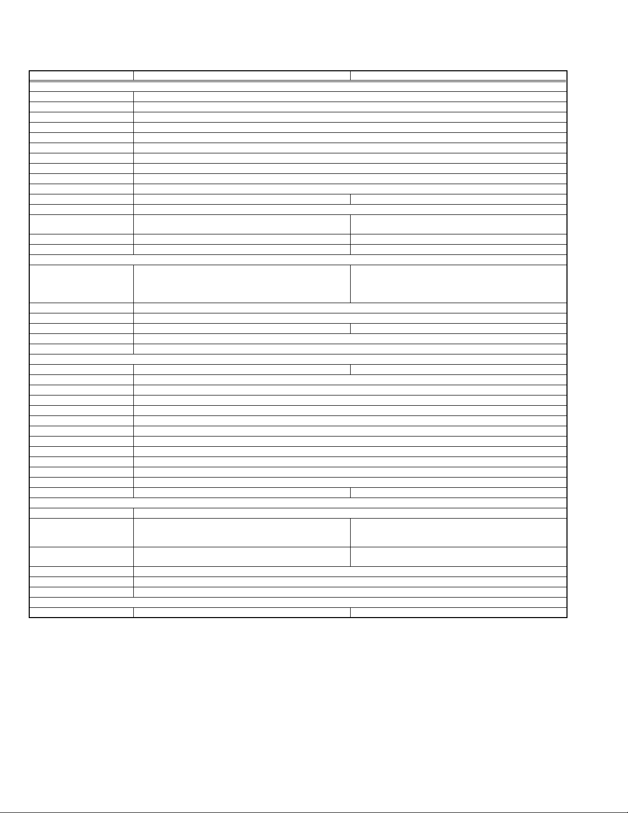
SPECIFICATION
GENERAL
Power requirement AC 110V - 240V, 50 Hz/60 Hz
Power consumption
Power on 26 W
Power off 6.0 W
Temperature
Operating 5°C to 40°C
Storage -20°C to 60°C
Operating position Horizontal only
Dimensions (W × H × D) 435 mm × 93 mm × 272 mm
Weight 4.4 Kg
Format VHS PAL/NTSC standard VHS NTSC standard
Maximum recording time
(SP) 240 min. with E-240 video cassette(PAL/MESECAM)
(LP) 480 min. with E-240 video cassette(PAL/MESECAM) -
(EP) 480 min. with T-160 video cassette(NTSC) 630 min. with ST-210 video cassette
VIDEO/AUDIO (VCR deck)
Signal system PAL-type colour signal and CCIR monochrome signal, 625
lines/50 fields
NTSC colour signal and EIA monochrome signal, 525 lines/
60 fields
Recording system DA4 (Double Azimuth) head helical scan system
Signal-to-noise ratio 45 dB
Horizontal resolution 250 lines (PAL/MESECAM)/220 lines (NTSC) 250 lines
Frequency range 70 Hz to 10,000 Hz (Normal audio) 20 Hz to 20,000 Hz (Hi-Fi audio)
Input/Output RCA connectors: IN × 2, OUT × 1
VIDEO/AUDIO (DVD deck)
Signal system NTSC 3.58 NTSC
Applicable disc DVD (12 cm, 8 cm), CD (12 cm, 8 cm)
Audio characteristics DVD:4 Hz - 22 KHz
Frequency response CD:4 Hz - 20 KHz
S/N Ratio 90 dB
Wow and flutter Below Measurable Level
Dynamic range 90 dB
Output
Component-Y (RCA) 1.0 Vp-p/75 Ω
Component-PB/PR (RCA) 0.7 Vp-p/75 Ω
Audio (RCA) 2 Vrms, 1 KΩ
S-VIDEO OUT × 1
Digital Audio -21 dBm to -15 dBm(peak) -21 dBm to -15 dBm(peak) PCM 48 KHz
TUNER/TIMER(VCR deck)
Tuning system Frequency synthesized tuner
Channel coverage VHF : (low) 42 MHz - 175 MHz/(high) 175 MHz - 470 MHz
UHF : 470 MHz - 870 MHz
Aerial/RF output UHF channels (Adjustable E28-E60) Channel 3 or 4 (switchable; preset to Channel 3 when
Clock reference Quartz
Program capacity 1-year programmable timer / 8 programs
Memory backup time Approx. 10 min.
ACCESSORIES
Provided accessories RF cable, Infrared remote control unit, "R6" battery × 2 RF cable, Infrared remote control unit, "AA" battery × 2
HR-XV3AA, HR-XV3AG, HR-XV3AS HR-XV3KR
210 min. with ST-210 video cassette
160 min. with T-160 video cassette(NTSC)
NTSC colour signal and EIA monochrome signal, 525 lines/
60 fields
VHF : Channels 2 - 13
UHF : Channels 14 - 69
CATV : 113 Channels
shipped) 75 Ω, unbalanced
Specifications shown are for SP mode unless otherwise specified.
E.& O.E. Design and specifications subject to change without notice.
Manufactured under license from Dolby Laboratories. "Dolby" and the double-D symbol are trademarks of Dolby Laboratories.
"DTS" and "DTS Digital Out" are trademarks of Digital Theater Systems, Inc.
1-2 (No.YD004)
Page 3

SECTION 1
PRECAUTION
Please refer to "HR-XV3EX No.YD002" about this section.
SECTION 2
SPECIFIC SERVICE INSTRUCTIONS
Please refer to "HR-XV3EX No.YD002" about this section except a written item.
2.1 DIFFERENT TABLE OF FEATURE
The following table indicates main different points between models HR-XV3EX, HR-XV3AA, HR-XV3AG, HR-XV3AS and HR-XV3KR.
MODEL NAME HR-XV3EX HR-XV3AA HR-XV3AG HR-XV3AS HR-XV3KR
POWER VOLTAGE 220-240V, 50/60Hz 110-240V, 50/60Hz ←←←
POWER PLUG CEE SAA CEE SASO KOREA
POWER SAVE DISPLAY OFF,MENU NOT USED ←←←
ANT.CABLE AERIAL EG ←←←F-F
HEAD CLEANER NOT USED USED ←←←
SHUTTLE SEARCH(LATCH)-
PAL
SHUTTLE SEARCH(LATCH)-
NTSC
VIDEO SYSTEM(VHS) PAL/
SQPB PAL(SP/LP) PAL(SP)/NTSC(SP) ←←NTSC(SP/EP)
RECORDING & PLAYBACK
SPEED
PICTURE CONTROL AUTO/EDIT/SOFT ←←←AUTO/EDIT/SOFT/
16:9(WIDE SCREEN) USED NOT USED ←←←
REAR L-1 INPUT SCART RCA ←←←
REAR L-2 INPUT SCART(DECODER) NOT USED ←←←
AV OUTPUT AUDIO(L/R) VIDEO,AUDIO(L/R) ←←←
COMPORNENT VIDEO
OUTPUT
DVD AUDIO out NOT USED AUDIO (L/R) ←←←
ANT. INPUT AERIAL EG ←←← F
RF OUTPUT AERIAL EG ←←← F
DVD VIDEO OUT NOT USED S-OUTPUT ←←←
BROADCASTING
STANDARD
NUMBER OF CH POSITIONS 99CH ←←←181CH
STEREO DECODER NICAM/A2 A2(B,G),NICAM(I,B,G,
RF OUT CH/RF OUT
SYSTEM[INITIAL]
AUTO CLOCK / JUST CLOCK USED NOT USED ←←←
VCR PLUS+ SHOWVIEW G-CODE/SHOWVIEW ←←G-CODE
AUTO GUIDE CH SET YES NO ←←←
REC LINK / INPUT YES/L-2 YES/L-1 ←←←
VPS/PDC USED NOT USED ←←←
LANGUAGE [VHS] 13 LANGUAGES ENGLISH ENGLISH/RUSSIAN/
LANGUAGE [DVD] ENGLISH/FRENCH/
T-V LINK USED NOT USED ←←←
DVD PROGRESSIVE NOT USED USED ←←←
REGION CODE REGIONAL CODE : 2 REGIONAL CODE : 4 REGIONAL CODE : 3 REGIONAL CODE : 2 REGIONAL CODE : 3
Note:
Mark ← is same as left.
SP/LP x7 ←←←NOT USED
NOT USED SPx7, EPx21 ←←SP,LPx7, EPx21
MESECAM(MANUAL)/
NTSC PB on PAL TV
with HiFi
SP,LP PAL:SP,LP/
NOT USED DVD:Y/Pb/Pr ←←←
B/G,D/K B/G,D/K,I ←←M
22-69CH,OFF[AUTO]/
G,K
GERMANY
PAL/MESECAM/
NTSC3.58/4.43/NTSC
PB on PAL TV with HiFi
NTSC:SP,EP
D,K)
28-60[36]CH,G[H]KI ←←[3]4CH,OFF, M
ENGLISH/CHINESE/
SPANISH
←←NTSC(SP/EP)
←←REC:SP/EP, PLAY:SP/
←←A2(KOREA)
ARABIC
←←←
← ENGLISH
LP/EP
SHARP
(No.YD004)1-3
Page 4

SECTION 3
DISASSEMBLY
Please refer to "HR-XV3EX No.YD002" about this section.
SECTION 4
ADJUSTMENT
Please refer to "HR-XV3EX No.YD002" about this section except a written item.
4.1 Before adjustment
4.1.1 Required test equipments
• Color (colour) television or monitor
• Oscilloscope: wide-band, dual-trace, triggered delayed sweep
• Signal generator: RF / IF sweep / marker
• Signal generator: stairstep, color (colour) bar [NTSC]
• Recording tape
• Digit-key remote controller(provided)
4.1.2 Required adjustment tools
Note:
When perform Mechanism compatibility or electrical adjustments of HR-XV3KR, use the alignment tape MHP and MHP-L.
--- : Not used
: Used
z
Mechanism
compatibility
adjustment
Roller driver z
Jig RCU --- z
Back tension cassette gauge z
Alignment tape(MHP) z ---
Alignment tape(MHP-L) zz
Roller driver
PTU94002
Jig RCU
PTU94023B
Back tension cassette gauge
Electrical
adjustment
---
---
PUJ48076-2
4.1.3 Color (colour) bar signal,Color (colour) bar pattern
Color(colour) bar signal [NTSC]
White(100%)
White(75%)
100 IRE
1V
40 IRE
Horizontal sync
Yellow
Cyan
Green
Magenta
Red
QI
Blue
Color(colour) bar pattern [NTSC]
(75%)
Burst
40 IRE
White
Yellow
White
Q I Black
100%
Cyan
Green
Magenta
Red
Blue
Alignment tape
(SP, stairstep, NTSC)
MHP
CD-DA test disc
CTS-1000
1-4 (No.YD004)
Alignment tape
(EP, stairstep, NTSC)
MHP-L
DVD test disc
VT-501
Page 5

4.2 Electrical adjustment [VHS SECTION]
Adjustment procedure and value are changed.
4.2.1 Servo circuit
4.2.1.1 Switching point [HR-XV3KR]
Signal (A1)
Mode (B) • PB
Equipment (C) • Oscilloscope
Measuring point (D1)
External trigger (E) • TP111 (D.FF)
Adjustment part (F) • Jig RCU: Code ”5A”
Specified value (G) • 6.5 ± 0.5H
Adjustment tool (H) • Jig RCU [PTU94023B]
(1) Play back the signal (A1) of the alignment tape (A2).
(2) Apply the external trigger signal to D.FF (E) to observe the
VIDEO OUT waveform and V.PB FM waveform at the mea-
suring points (D1) and (D2).
(3) Set the VCR to the manual tracking mode.
(4) Adjust tracking so that the V.PB FM waveform becomes
maximum.
(5) Set the VCR to the Auto adjust mode by transmitting the
code (F) from the Jig RCU. When the VCR enters the stop
mode, the adjustment is completed.
(6) If the VCR enters the eject mode, repeat steps (1) to (5)
again.
(7) Play back the alignment tape (A2) again, confirm that the
switching point is the specified value (G).
Trigger point
• Stairstep signal
(A2)
• Alignment tape(EP,stairstep,NTSC) [MHP-L]
• VIDEO OUT terminal (75 ohm terminated)
(D2)
• TP106 (PB. FM)
Switching point
V.sync
4.2.1.2 Slow tracking preset
Signal (A1)
Mode (B1)
Measuring point (D) TV-Monitor
Adjustment part (F) Jig RCU: Code "71" or "72"
Specified value (G) minimum noise
Adjustment tool (H) Jig RCU [PTU94023B]
Ext. input
(A2)
Color (colour) bar signal [NTSC]
(A3)
Color (colour) bar signal [PAL]
VHS SP (NTSC) [HR-XV3KR]
(B2)
VHS EP (NTSC) [HR-XV3KR]
(B3)
VHS SP (PAL)
(B4)
VHS LP (PAL)
(1) Record the signal (A2) in the mode (B1), and play back the
recorded signal.
(2) Set the VCR to the manual tracking mode.
(3) Set the VCR to the FWD slow (+1/6x) mode.
(4) Transmit the code (F) from the Jig RCU to adjust so that the
noise bar becomes the specified value (G) on the TV mon-
itor in the slow mode.
(5) Set the VCR to the Stop mode.
(6) Confirm that the noise bar is (G) on the TV monitor in the
slow mode.
(7) Repeat steps (3) to (6) in the REV slow (-1/6x) mode.
(8) Repeat steps (1) to (7) in the mode (B2).
(9) Record the signal (A3) in the mode (B3), and play back the
recorded signal.
(10) Repeat steps (2) to (7)
(11) Repeat steps (9) and (10) in the mode (B4).
Note:
For FWD slow (+1/6x) playback, transmit the code "08" from
the Jig RCU to enter the slow playback mode, and transmit the
code "D0" for REV slow ( 1/6x) mode.
V. rate
Fig.4-2a Switching point
SECTION 5
TROUBLESHOOTING
Please refer to "HR-XV3EX No.YD002" about this section.
(No.YD004)1-5
Page 6

VICTOR COMPANY OF JAPAN, LIMITED
AV & MULTIMEDIA COMPANY VIDEO RECORDER CATEGORY 12, 3-chome, Moriya-cho, kanagawa-ku, Yokohama, kanagawa-prefecture, 221-8528, Japan
(No.YD004)
Printed in Japan
WPC
 Loading...