

Page 1
SERVICE MANUAL
DVD PLAYER / VIDEO CASSETTE RECORDER
HR-XV2EK
POWER
VCR DVD
TV
DVD MENU MEMORY
SUBTITLE ANGLE
DISPLAY
REPEAT A-B ZOOM
123
456
7089
AUX
AUDIO
MONITOR
SEARCH
EJECT
RETURN
REPEAT
TITLE
SHOWVIEW
VIDEO Plus+
TV
TV
TV/VCR
TV/VCR PR +
OK
0000
CANCEL
RANDOM
TV/VCR PR
.
PROG
PAL
SPECIFICATIONS
General
Power requirements AC 200-240V, 50/60 Hz
Power consumption Operation mode : 23W
Dimensions (approx.) 430 X 97.5 X 293 mm (w/h/d)
Mass (approx.) 4.8 kg
Operating temperature 5˚C to 35˚C (41˚F to 95˚F)
Operating humidity 5 % to 90 %
Timer 24 hours display tape
Program capacity 1 month 7 program
RF Modulator UHF 22-68 (Adjustable)
System
Laser Semiconductor laser, wavelength 650 nm
Video Head system Double azimuth 4 heads, helical scanning.
Signal system PAL
Frequency response DVD (PCM 96 kHz): 8 Hz to 44 kHz
Signal-to-noise ratio More than 100dB (ANALOG OUT connectors only)
Harmonic distortion Less than 0.008%
Dynamic range More than 100 dB (DVD)
Inputs (VCR)
Audio -6.0dBm, more than 10 kohms (SCART)
Video 1.0 Vp-p, 75 ohms, unbalanced (SCART/RCA)
Standby mode : 6.7W
DVD (PCM 48 kHz): 8 Hz to 22 kHz
CD: 8 Hz to 20 kHz
More than 95 dB (CD)
-6.0dBm, more than 47 kohms (RCA)
Outputs (DVD)
S-VIDEO OUT (Y) 1.0 Vp-p 75 ohms, negative sync., Mini Din 4-pin x 1
(C) 0.3 Vp-p 75 ohms
COMPONENT VIDEO OUT (Y) 1.0 V (p-p), 75 Ω, negative sync, RCA jack x 1
Audio output (digital audio) 0.5 V (p-p), 75 Ω, RCA jack x 1
(Pb)/(Pr) 0.7 V (p-p), 75 Ω, RCA jack x 2
Audio output (optical audio) 5 V (p-p), 75 Ω, Optical connector x 1
Audio output (analog audio) 2.0 Vrms (1 kHz, 0 dB), 330 Ω, RCAjack (L, R) x 2/SCART(TO TV)
Outputs (VCR)
Audio -6.0dBm, less than 1 kohms (SCART)
Video 1.0Vp-p, 75 ohms, unbalanced (SCART)
Design and specifications are subject to change without notice.
Manufactured under license from Dolby Laboratories. “ Dolby” and double-D symbol are trademarks of
Dolby Laboratories. Confidential Unpublished Works. ©1992-1997 Dolby Laboratories, Inc. All rights reserved.
Manufactured under license from Digital Theater Systems, Inc. US Pat. No. 5,451,942 and other world-wide patents issued and
pending. “ DTS” and “ DTS Digital Out” are trademarks of Digital Theater Systems, Inc. Copyright 1996 Digital Theater Systems, Inc.
All rights reserved.
COPYRIGHT © 2003 VICTOR COMPANY OF JAPAN, LTD
HR-XV2EK D2VP11
No.82985
2003/06
Page 2

CONTENTS
SECTION 1 . . . . SUMMARY
SECTION 3 . . . . ELECTRICAL
SECTION 4 . . . . MECHANISM OF VCR PART
SECTION 5 . . . . MECHANISM OF DVD PART
SECTION 6 . . . . REPLACEMENT PARTS LIST
Page 3

SECTION 1
SUMMARY
CONTENTS
Safety Precautions
SPECIFICATIONS ................................................................................................... 1-5
Page 4

Safety Precautions
1. This design of this product contains special hardware and many circuits and components specially
for safety purposes. For continued protection, no changes should be made to the original
design unless authorised in writing by the manufacturer. Replacement parts must be identical to
those used in the original circuits.
2. Any unauthorised design alterations or additions will void the manufacturer's guarantee ; furthermore the
manufacturer cannot accept responsibility for personal injury or property damage resulting therefrom.
3. Essential safety critical components are identified by ( ) on the Parts List and by shading on the
schematics, and must never be replaced by parts other than those listed in the manual. please note
however that many electrical and mechanical parts in the product have special safety related
characteristics. These characteristics are often not evident from visual inspection. Parts other than
specified by the manufacturer may not have the same safety characteristics as the recommended
replacement parts shown in the Parts List of the Service manual and may create shock, fire, or
other hazards.
4. The leads in the products are routed and dressed with ties, clamps, tubings, barriers and the
like to be separated from live parts, high temperature parts, moving parts and/or sharp edges
for the prevention of electric shock and fire hazard. When service is required, the original lead
routing and dress should be observed, and it should be confirmed that they have been returned
to normal, after re-assembling.
Warning
1. Service should be performed by qualified personnel only.
2. This equipment has been designed and manufactured to meet international safety standards.
3. It is the legal responsibility of the repairer to ensure that these safety standards are maintained.
4. Repairs must be made in accordance with the relevant safety standards.
5. It is essential that safety critical components are replaced by approved parts.
6. If mains voltage selector is provided, check setting for local voltage.
S40892-01
Page 5

SPECIFICATIONS
DVD PART
Power supply AC 110~240V, 50/60 Hz(HR-XV2ER)
AC 200~240V, 50/60 Hz(HR-XV2EX/HR-XV2EY/
HR-XV2EL/HR-XV11EX/ HR-XV2EK/HR-XV2EF/HR-XV2EZ)
Power consumtion 23W
Mass 5.4kg
External dimensions 430 x 97.5 x 293 (W x H x D)
Signal system PAL 625/50
Laser Semiconductor laser, wavelength 650nm
Frequency range (digital audio) 4 Hz to 20 kHz
Signal-to-noise ratio (digital audio) More than 100 dB (EIAJ)
Audio dynamic range (digital audio) More than 95 dB (EIAJ)
Harmonic distortion(digital audio) 0.008%
Wow and flutter Below measurable level (less than +0.001%(W.PEAK)) (EIAJ)
Operations Temperature : 5˚C(41˚F) to 35˚C(95˚F),
Operation status : Horizontal
OUTPUTS
Video outputs .0V(p-p), 75Ω, negative sync., RCA jack x 1/SCART(TO TV)
S video outputs
Component video output (Y) 1.0 V (p-p), 75 Ω, negative sync., RCA jack x 1
Audio output(digital audio) 0.5V(p-p), 75Ω, RCA jack X 1/SCART(TO TV)
Audio output(optical audio) Optical connector x 1
Audio output(analog audio) 2.0Vrms (1kHz, 0dB), 330Ω, RCAjack (L, R) x 1/
VHS PART
Video Head System Double azimuth 4 heads, helical scanning
Tape format Tape width 12.7 mm (0.5 inch)
Timer 24 hours display type
*Designs and specifications are subject to change without notice.
*Weight and dimensions shown are approximate.
1
(Y)1.0V(p-p), 75Ω, negative sync.,Mini DIN 4-pin x 1
(C)0.3V(p-p), 75Ω
(Pb)/(Pr) 0.7 V (p-p), 75 Ω
SCART(TO TV)
1-5
Page 6

SECTION 3
ELECTRICAL
CONTENTS
OVERALL BLOCK DIAGRAM
.............................3-2
VCR PART
ELECTRICAL ADJUSTMENT
PROCEDURES
..........................................................3-3
ELECTRICAL TROUBLESHOOTING
GUIDE
BLOCK DIAGRAMS
CIRCUIT DIAGRAMS
...........................................................................3-4
1. POWER(SMPS) CIRCUIT.......................................3-4
2. SYSTEM/KEY CIRCUIT ..........................................3-7
3. SERVO CIRCUIT.....................................................3-8
4. Y/C CIRCUIT..........................................................3-11
5. Hi-Fi CIRCUIT .......................................................3-15
6. Tuner/IF CIRCUIT.................................................3-18
..............................................3-20
1. Power(SMPS) BLOCK DIAGRAM .......................3-20
2. Tu/IF, NICAM & A2 BLOCK DIAGRAM................3-22
3. VPS BLOCK DIAGRAM........................................3-23
4. Y/C BLOCK DIAGRAM.........................................3-24
5. Hi-Fi BLOCK DIAGRAM.......................................3-26
6. SYSTEM BLOCK DIAGRAM................................3-28
............................................3-30
1. Power(SMPS) CIRCUIT DIAGRAM......................3-30
2. TU/IF, NICAM & A2 CIRCUIT DIAGRAM .............3-32
3. A/V CIRCUIT DIAGRAM .......................................3-34
4. Hi-Fi CIRCUIT DIAGRAM.....................................3-36
5. SCART(JACK) CIRCUIT DIAGRAM ....................3-38
6. SYSTEM CIRCUIT DIAGRAM ..............................3-40
• WAVEFORM & VOLTAGE SHEET.........................3-42
• CIRCUIT VOLTAGE CHART...................................3-44
DVD PART
ELECTRICAL TROUBLESHOOTING
GUIDE & WAVEFORMS
1. System Clock X501 (27Mhz) ...............................3-52
2. Initializing between MPEG and SDRAM ............3-52
3. Initializing between MPEG and Flash ................3-53
4. Reference Voltage 1.............................................3-53
5. Reference Voltage 2.............................................3-54
6. Checking the initial step of M/D Ass’y...............3-54
7. Checking the Video Signal..................................3-55
8. Checking the first step of servo (1) ...................3-55
9. Checking the second step of servo (2) .............3-56
10. Checking the output of Audio signal ...............3-56
11. Checking the reset port.....................................3-57
12. Checking the focus & tracking servo..............3-57
13. Checking the track jump...................................3-58
14. The status of CD_LD and DVD_LD in the
PLAY MODE........................................................3-58
15. The status Focus and spindle motor ...............3-59
16. DATA STREAM ...................................................3-59
17. Input Clock to IC202..........................................3-60
18. Tray Open and Close.........................................3-60
19. Focus Drive signal(FACT) .................................3-61
20. Signals for Front micom ...................................3-61
21. FACT and FE for DVD9 (Dual disc)..................3-62
22. System clock of MPEG IC.................................3-62
BLOCK DIAGRAMS
1. DVD Overall Block Diagram................................3-63
2. SERVO Block Diagram........................................3-64
3. MPEG Block Diagram..........................................3-65
4. AUDIO Block Diagram .........................................3-66
.......................................3-52
..............................................3-63
PRINTED CIRCUIT DIAGRAMS
1. MAIN P.C.BOARD .................................................3-48
2. SMPS P.C.BOARD ...............................................3-50
.......................3-48
CIRCUIT DIAGRAMS
1. RD SERVO CIRCUIT DIAGRAM..........................3-67
2. SYSTEM CIRCUIT DIAGRAM ..............................3-69
3. AUDIO CIRCUIT DIAGRAM..................................3-71
4. INTERFACE CIRCUIT DIAGRAM.........................3-73
• CIRCUIT VOLTAGE CHART...................................3-75
PRINTED CIRCUIT DIAGRAMS
1. MAIN P.C.BOARD (TOP VIEW)............................3-79
2. MAIN P.C.BOARD (BOTTOM VIEW) ....................3-81
............................................3-67
.......................3-79
3-1
Page 7
ELECTRICAL ADJUSTMENT PROCEDURES
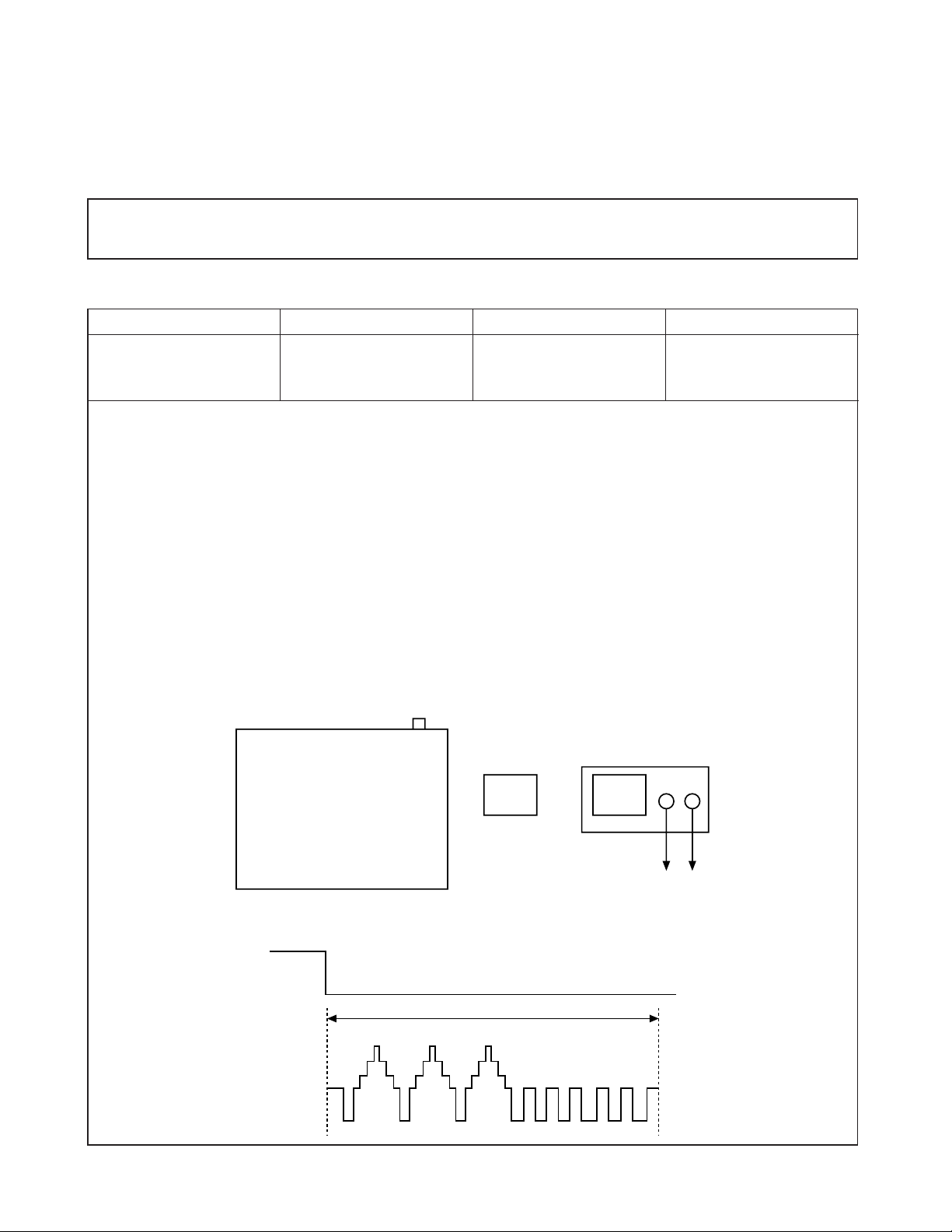
1. Servo Adjustment
1) PG Adjustment
VCR PART
•Test Equipment
a) OSCILLOSCOPE
b) NTSC MODEL : NTSC SP TEST TAPE
C) PALMODEL : PAL SP TEST TAPE
• Adjustment And Specification
MODE
PLAY
MEASUREMENT POINT ADJUSTMENT POINT SPECIFICATION
V.Out
H/SW
R/C TRK JIG KEY 6.5 ± 0.5H
• Adjustment Procedure
a) Insert the SP Test Tape and play.
Note - Adjust the distance of X, pressing the Tracking(+) or Tracking(-) when the “ATR” is blink after the
SP Test Tape is inserted.
b) Connect the CH1 of the oscilloscope to the H/SW and CH2 to the Video Out for the VCR.
c) Trigger the mixed Combo Video Signal of CH2 to the CH1 H/SW, and then check the distance (time dif-
ference), which is from the selected A(B) Head point of the H/SW signal to the starting point of the vertical synchronized signal, to 6.5H ± 0.5H (412µs, 1H=63µs).
• PG Adjustment Method
a-1) Payback the SP standard tape
b-2) Press the “1” key on the Remote controller and the “PLAY” key on the Front Panel at the same time,
then it goes into Tracking initial mode.
c-3) Repeat the above step(No.b-2), then it finishes the PG adjusting automatically.
d-4) Stop the playback, then it goes out to PG adjusting mode after mony the PG data.
• CONNECTION
• WAVEFORM
H/SW
T/P
H/SW
Composite
VIDEO
V.Out
OSCILLOSCOPE
CH1 CH2
R/C KEY
V.outH/SW
6.5H(412us)
3-3
Page 8
ELECTRICAL TROUBLESHOOTING GUIDE
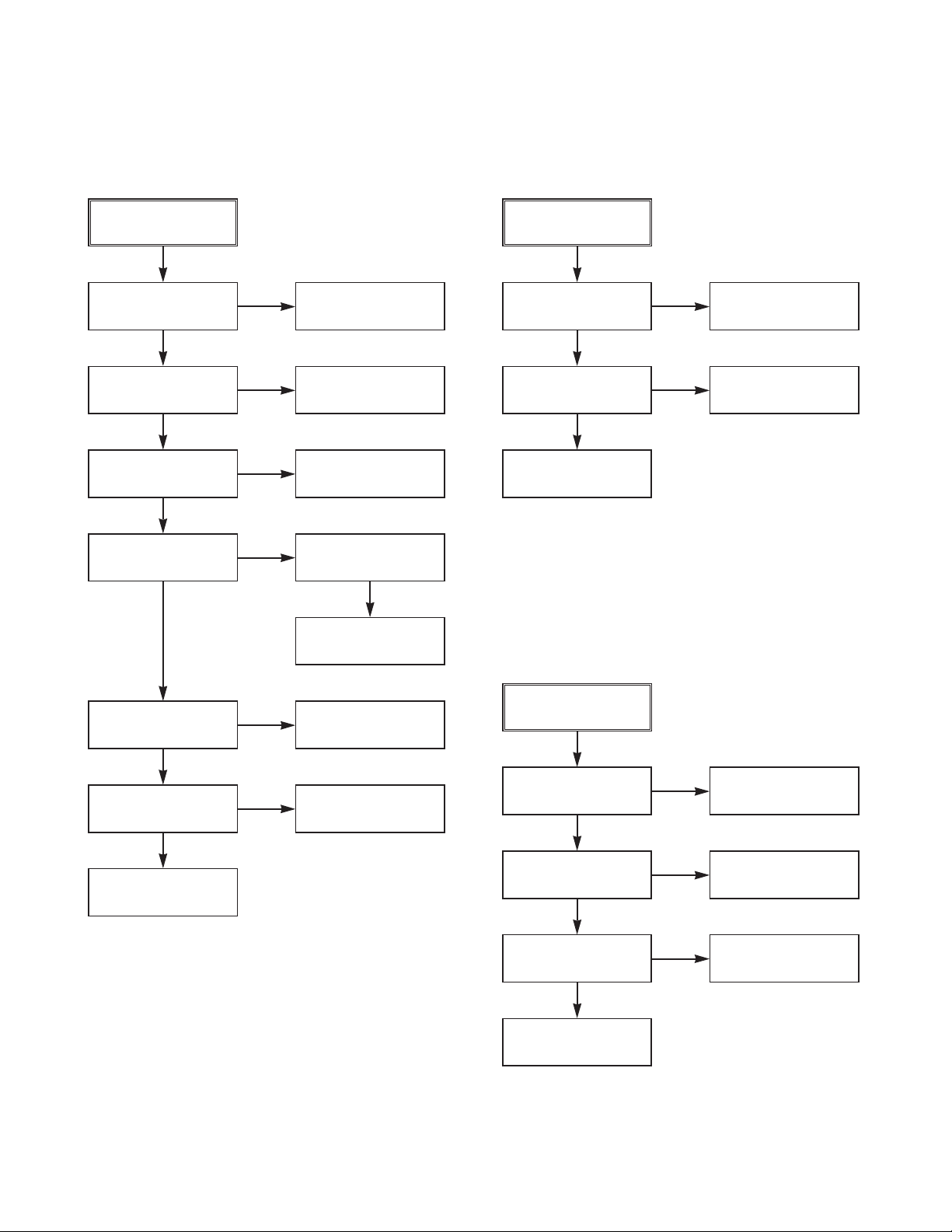
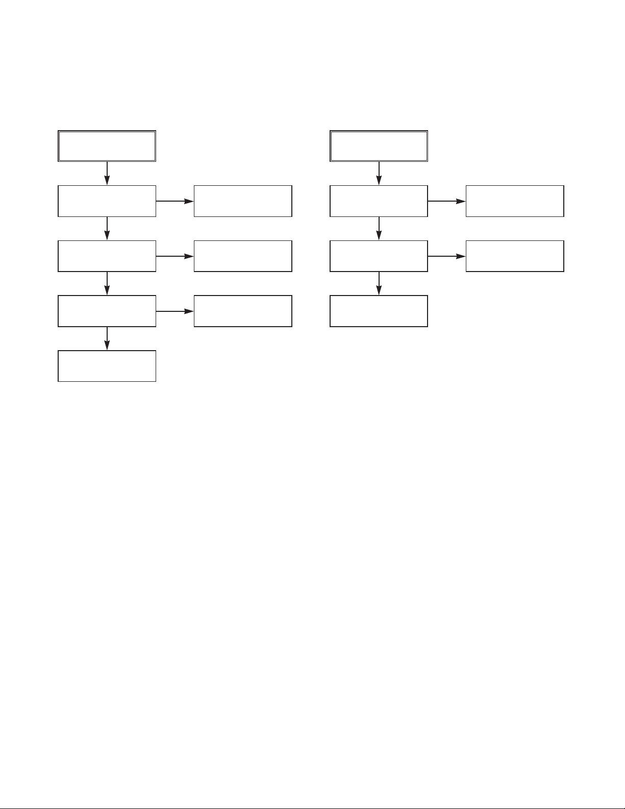
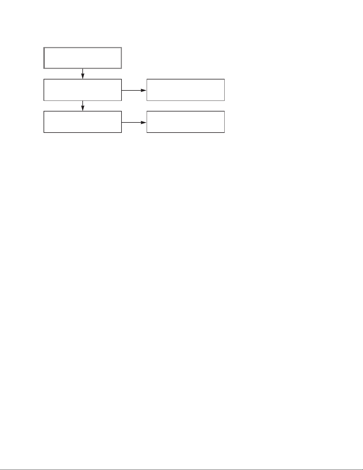
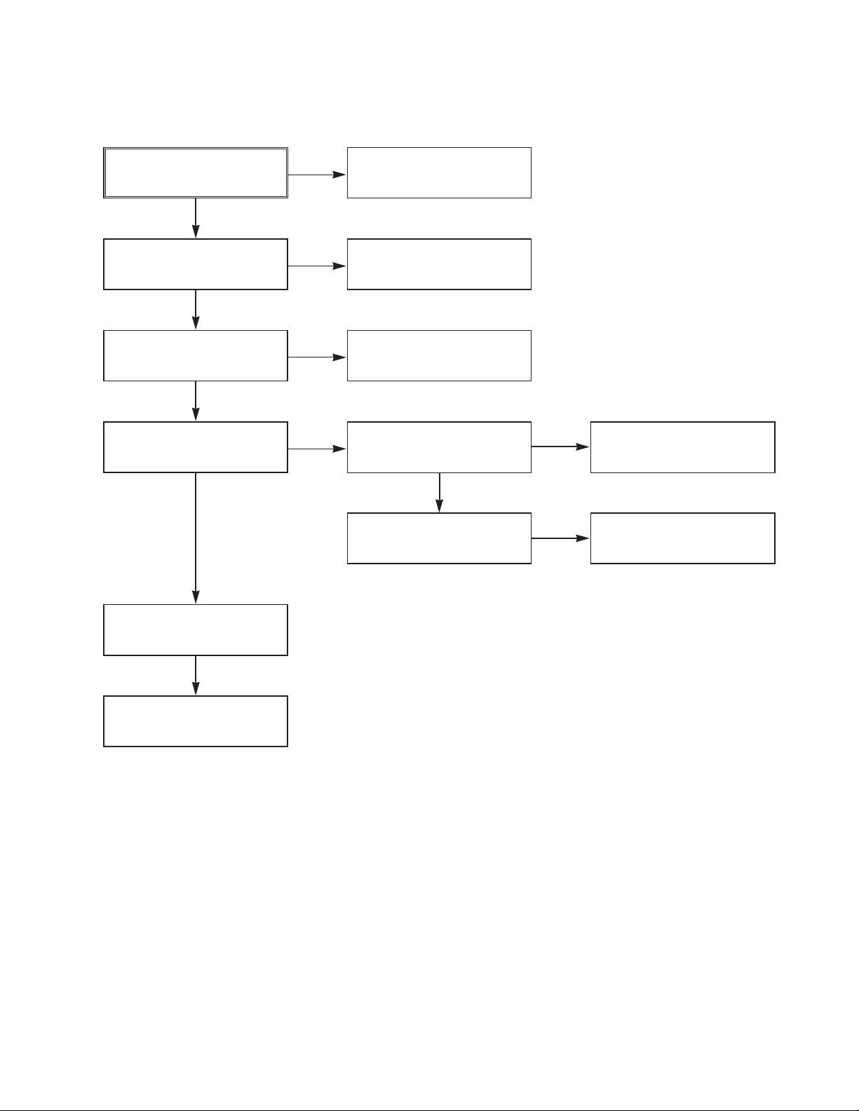
1. Power(SMPS) CIRCUIT
(1) No 5.3VA (SYS/TUNER)
NO 5.3VA.
YES
Is the F101 normal?
YES
Is the BD101
NO
NO
normal?
YES
Is the R101
NO
normal?
YES
Is Vcc(8.5~21V) sup-
NO
plied to IC101 Pin7?
YES
Replace the F101.
(Use the same Fuse)
Replace the
BD101.
Replace the R101.
Is the D102
normal?
NO
Check or Replace
the D102.
(2) No 12VA (TO CAP, DRUM MOTOR)
NO 12VA.
YES
Is the Vcc(13V) supplied
NO
to (+) terminal in D115?
YES
Is the Vcc(12V) supplied
NO
to (-) terminal in D115?
YES
Check or Replace
the D110.
Replace the D115.
Check or Replace
the Motor Vcc.
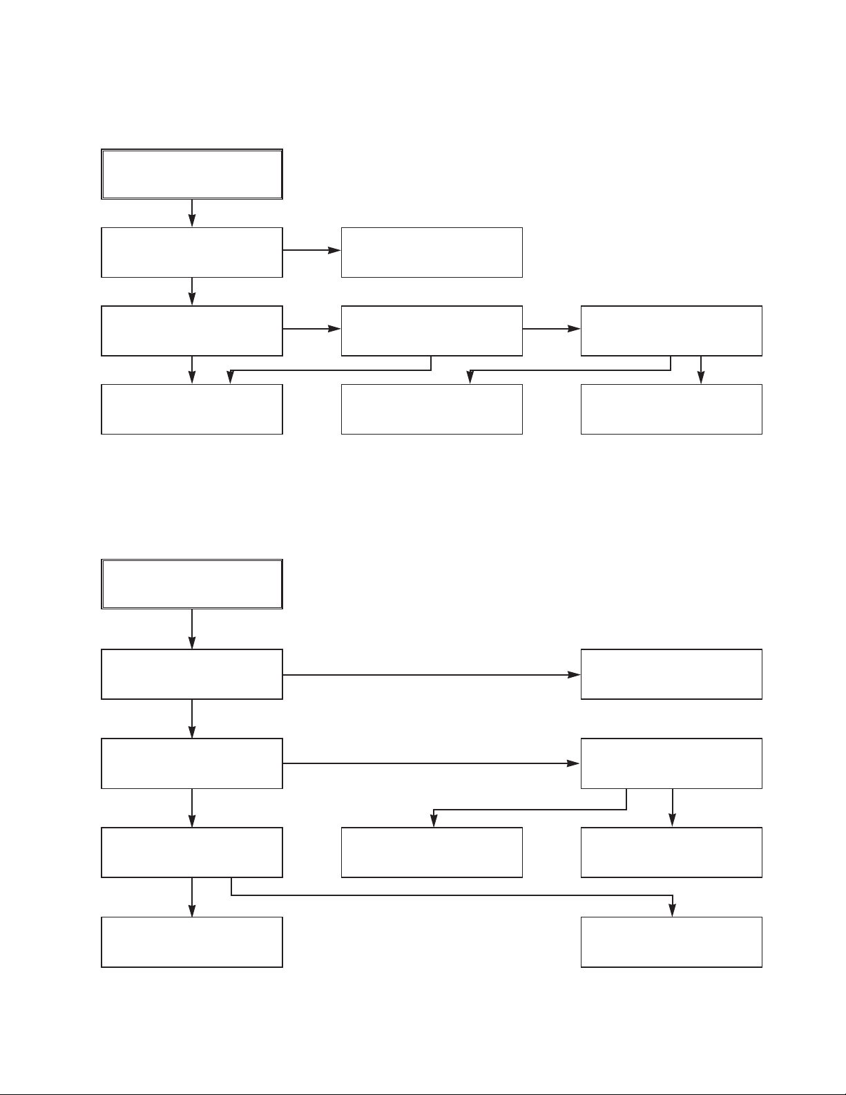
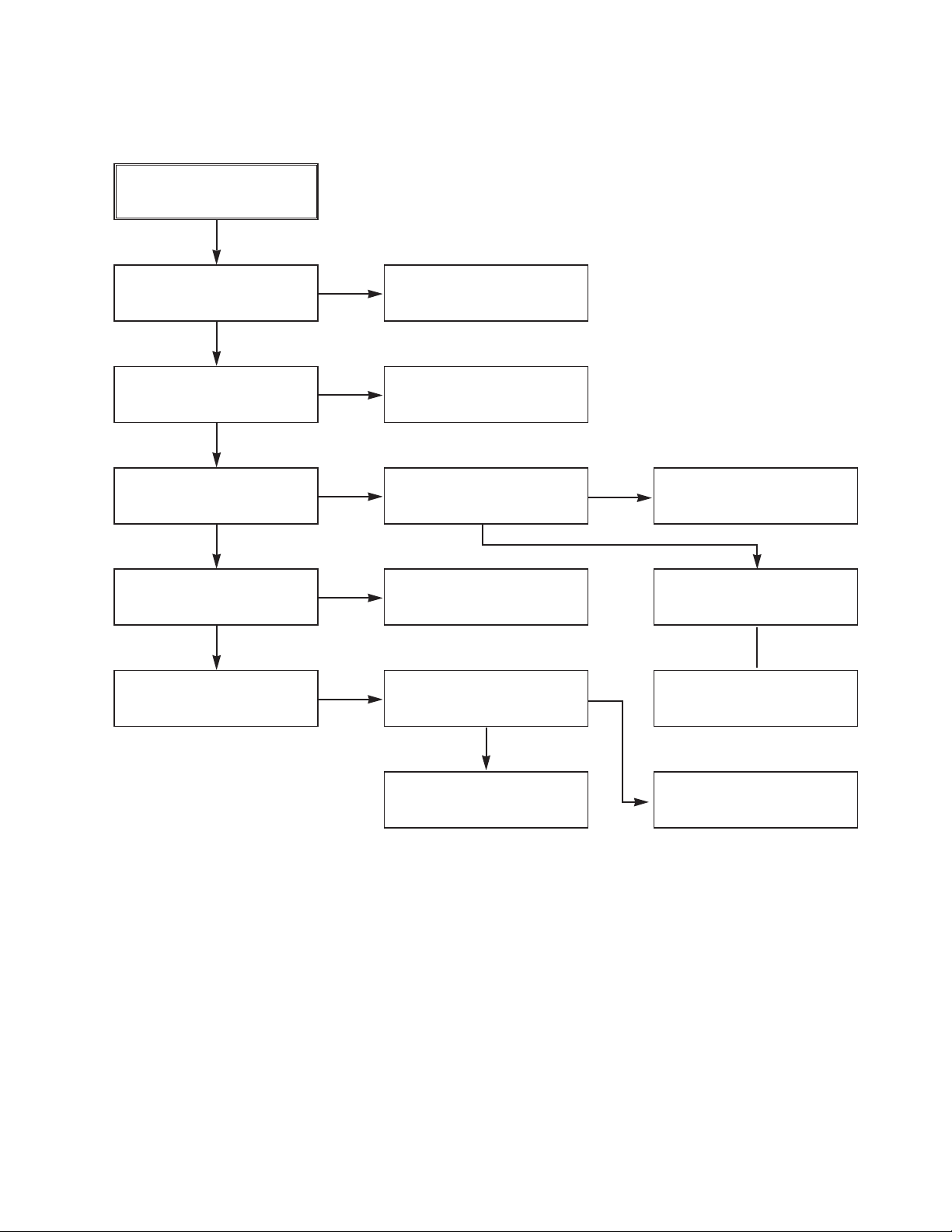
(3) No 5.0V (SYS, Hi-Fi, TUNER, Y/C)
Is the D112 normal?
YES
Is there about 2.5V
at the IC103 Vref?
YES
Check the Main PCB
5.3VA/5.0V Line short?
NO
NO
Replace the D112.
Replace the IC103.
NO 5.0VA.
YES
Is 5.3VA put into
the Q160 Emitter?
YES
Is the Q162 Base
“H”?
YES
Is about 5V put into
the Q160 Base?
YES
Check or Replace
the Q162/Q160.
NO
NO
NO
5.3VA Line Check.
Check the Power
Control.
Check or Replace the Q162,
R157, R158, R159, D121.
3-4
Page 9
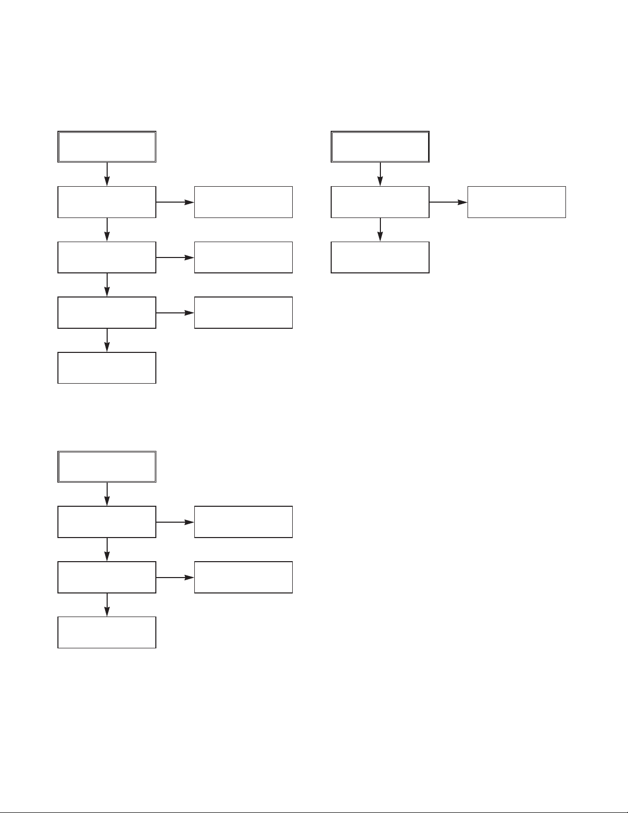
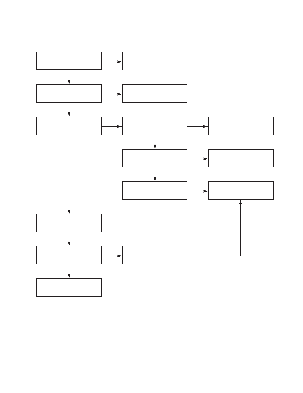
(4) No 5V (TO DVD)
(5) No 33V (TUNER)
NO 5V.
YES
Is 5.3VA put into
the Q160 Emitter?
YES
Is the Q162 Base
“H”?
YES
Is about 5V put into
the Q160 Base?
YES
Check or Replace
the Q162/Q160
(6) No REG 12V
NO
NO
NO
5.3VA Line Check.
Check the Power
Control.
Check or Replace the Q162,
R157, R158, R159, D121.
No 33V.
YES
Is Q162 Base “H”?
YES
Check or Replace
Q161, R154, R155.
NO
Check the Power
Control.
No REG 12V.
YES
Is 13V put into the
NO
Q156 Collector?
YES
Is 13V put into the
NO
R153 Base?
YES
Check or Replace the Q156,
ZD103, R153, C151.
Check or Replace
D110.
Check 33V Line.
3-5
Page 10
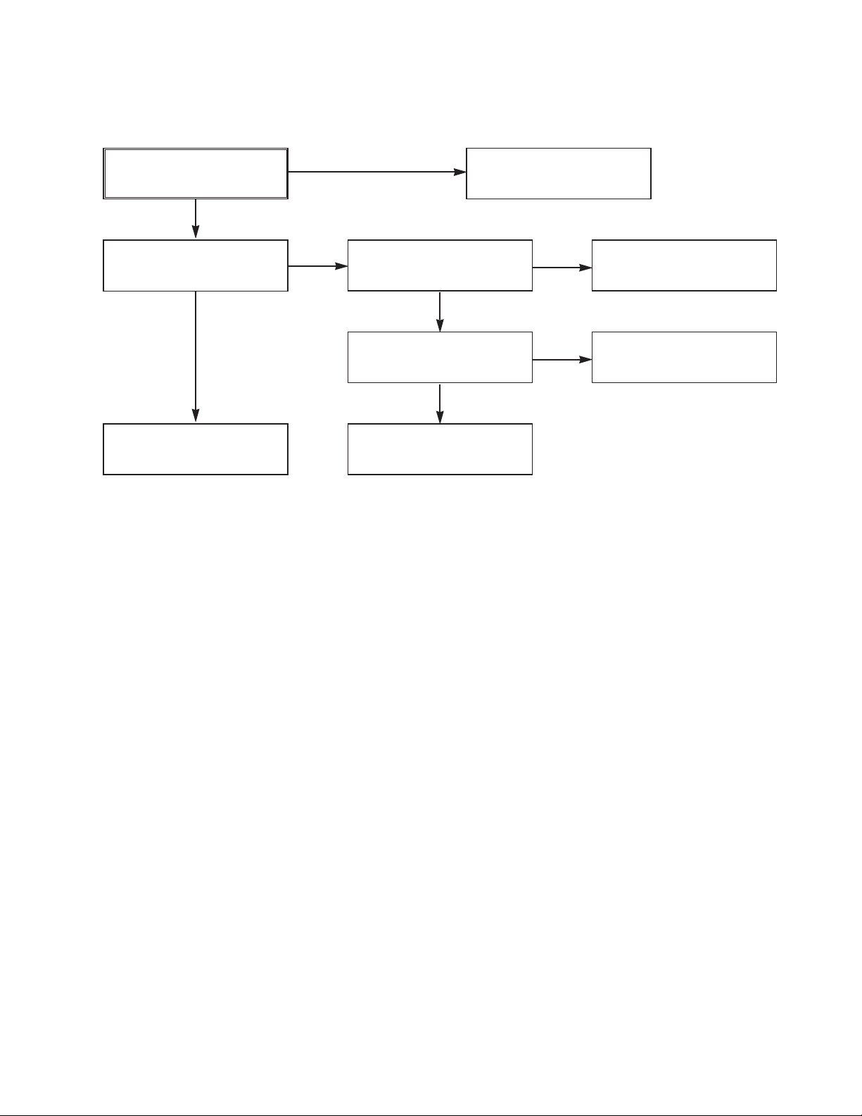
(7) No 8V(TO DVD)
(8) No 3.3V(TO DVD)
NO 8V.
YES
Is Vcc(13V) supplied to
(+) terminal in D114?
YES
Is Vcc(12V) supplied
to IC151 Pin1?
YES
Is the Q162 Base
“H”?
YES
Check or Replace
IC151, R170, C154.
NO
NO
NO
Check or Replace
the D110.
Check or Replace
the D114.
Check the Power
Control.
NO 3.3V.
YES
Is Vcc(4V) supplied
to IC152 Pin1?
YES
Is the Q162 Base
“H”?
YES
Check or Replace
IC152, R156, C153.
NO
NO
Check or Replace
the D111.
Check the Power
Control.
3-6
Page 11
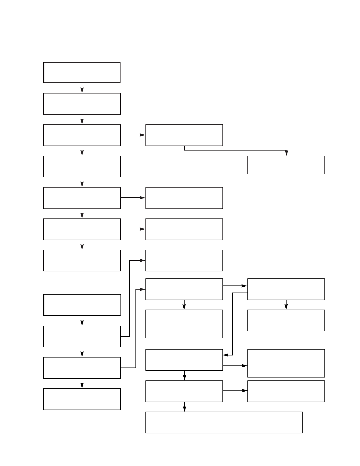
2. SYSTEM/KEY CIRCUIT
(1) AUTO STOP
Auto Stop
YES
Does the SW25 waveform
appear at the IC501
Pin105?
YES
Do the T-UP Reel Pulses
appear at the IC501 Pin49?
YES
Replace the IC501.
NO
NO NO
Check the Drum Motor
signal.
Do T/UP Reel Pulses
appear at the Q514
Base terminal ?
YES YES
Replace the T/UP Reel
Sensor (RS501).
(2) The unstable loading of a Cassette tape
The unstable loading of a
Cassette tape
YES
Does 5.2V appear at the
RS501?
NO
Check the Power Circuit.
Is 12V applied to the
PMC01 Pin8?
YES
Does the “H” signal appear
at the IC501 Pin30 during
inserting the CST ?
YES
Does the “L” signal appear
at the IC501 Pin72 during
inserting the CST?
YES
Check the Deck
Mechanism.
Caution :
Auto stop can occur because Grease or Oil is dried up
NO
NO
NO
Check the CST SW and
the peripheral circuitry.
3-7
Check the Power.
Is 5.3V applied to the
R544 ?
YES
Refer to SMPS 5.3VA
troubleshooting.
Check the IC501
Pins68, 69, 70, 71.
NO
Page 12
3. SERVO CIRCUIT
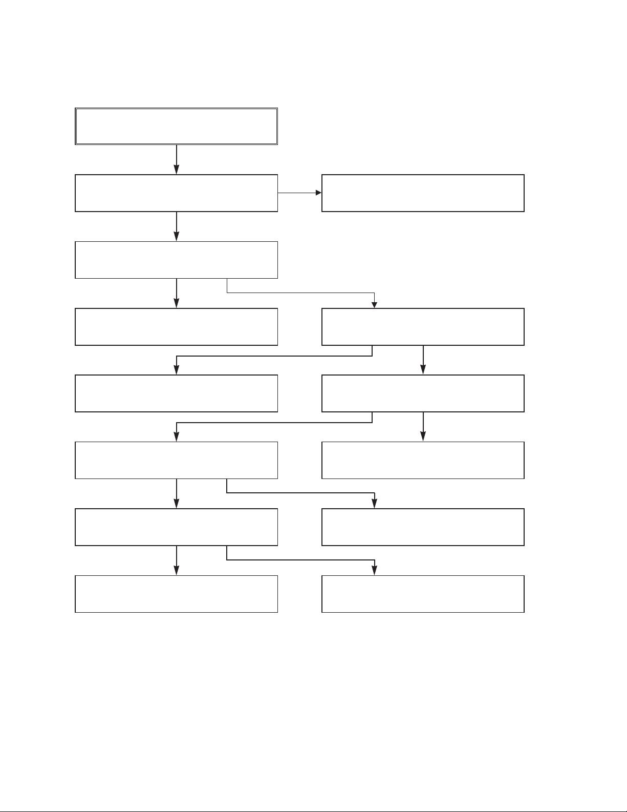
(1) Unstable Video in PB MODE
Unstable Video in
PB Mode.
YES
Does the Noise level of the
screen change
periodically?
YES
Do the CTL pulses appear
at the IC501 Pin8?
YES
Does the CFG waveform
appear at the IC501
Pin9?
YES
On tracking do the CTL
pulses move?
YES
Does the Video Envelope
waveform appear at the
IC501 Pin24?
YES
Replace the IC501.
(2) When the Drum Motor
(2) doesn’t run.
When the Drum Motor
doesn’t run,
Does 12V appear at the
PMC01 Pin8?
NO
NO
NO
NO
Is adjusting the height of
the CTL Head accurate?
Replace the IC501.
Refer to “When the Y signal
doesn’t appear on the
screen in PB Mode”.
Refer to “(2)
No 12VA of Power section”
Do the Drum PWM Pulses
appear at the IC501
Pin107?
YES
Aren’t the foil patterns and
the Components between
IC501 Pin107 and PMC01
Pin12 short?
NO
Readjust the height of the
CTL Head.
NO
Do the DFG Pulses appear
at the PMC01 Pin11?
YES
NO
Replace the Cap M.
YES
Does 2.8V appear at the
PMC01 Pin12?
YES
Check the connector
(PMC01) and the Drum
Motor Ass’y .
NO
Do the DFG Pulses appear
at the IC501 Pin104?
YES
Do the Drum PWM Pulses
appear at the IC501
Pin107?
YES
Aren’t the connecting patterns and the Components
between IC501 Pin107 and PMC01 Pin12 short?
3-8
NO
NO
Aren’t the foil patterns and
the Components between
IC501 Pin104 and PMC01
Pin11 short?
Replace the IC501.
Page 13
2. SERVO CIRCUIT
(3) When the Capstan Motor doesn’t run,
When the Capstan Motor doesn’t run,
Does 12VA appear at the PMC01?
YES
Does 2.8V appear at the PMC01?
YES
Check the PMC01 and the Capstan
Motor Ass’y .
Aren’t the foil patterns and Components
between IC501 Pin108 and PMC01
Pin9 short?
Does the CFG signal come into the
IC501 Pin9?
NO
NO
YES
YES
Refer to “SMPS(CAPSTAN/12Volt)
Trouble Shooting”.
Does the PWM signal appear at the
IC501 Pin108?
NO
Does the CFG signal appear at the
PMC01 Pin1?
NO
Check the Capstan Motor Ass’y.
YES
Does the Capstan PWM signal appear at
the IC501 Pin108?
YES
Aren’t the foil patterns and Components
between IC501 Pin108 and PMC01
Pin9 short?
NO
Aren’t the foil patterns and component
between IC501 Pin9 and PMC01
Pin1 short?
NO
Replace the IC501.
3-9
Page 14
(4) KEY doesn’t working
KEY doesn’t working.
Is 5V applied to the IC501
Pin36?
YES
Does LED or FLD change
when a function button is
pressed?
NO
NO
Refer to “SMPS 5.3VA
Trouble Shooting”.
Replace the defective
switches.
3-10
Page 15
4. Y/C CIRCUIT
(1) No Video in EE Mode,
No Video in EE Mode
Does the Video signal
appear at the IC301 Pin15?
YES
Is 5V applied to the IC301
Pins4, 22, 47, 60, 84?
YES
Does the Video signal
appear at the IC301 Pin29?
YES
Does the Video signal
appear at the IC501 Pin19?
YES
Does the Video signal
appear at the Emitter terminal of the Q805?
NO
NO
NO
NO
NO
Check the 24Pin of Tuner.
Check the 5.2VT, 5.3VA
Line. (Power Circuit)
Is I2C BUS signal applied to
the IC301 Pins73, 74?
YES
Chck the path of the signal
between the IC301 Pin29
and IC501 Pin17.
Does the 12VT, 5.4VA
appear at the Emitter terminal of the Q805.
NO
NO
Check the System Circuit.
(Refer to ‘SYSTEM I
CHECK Trouble Shooting’)
Check C327. (AGC)
Replace the IC301.
YES
2
C BUS
YES
Replace the Q805.
3-11
Check the 12VT, 5.4VA
Line. (Power Circuit)
Page 16
3. Y/C CIRCUIT
(2) When the Y(Luminance) signal doesn’t appear on the screen in PB Mode,
Is 5.2VT, 5.3VA applied to the
IC301 Pins22, 47, 60, 84?
YES
Is the I2C Bus siganl applied
to the IC301 Pins73, 74 ?
YES
Does the normal RF signal
appear at the IC301 Pin76?
YES
NO
NO
NO
Check the line of the 5.2VT,
5.3VA Line. (Power Circuit)
Refer to ‘SYSTEM I2C BUS
CHECK Trouble Shooting’.
Is the V.H.S/W signal
applied to the IC301 Pin80?
YES
Is V.H.S/W “H” about 3.4V
at the IC301 Pin80?
YES
Clean the Drum.
NO
NO
NO
Check the System Circuit.
(IC501 Pin105)
Check the V.H.S/W level.
(Check R335)
Replace the IC301.
Does the Y(Luminance) RF
signal appear at the IC301
Pin9?
YES
Is the Y(Luminance) Video
waveform showed up at
theIC301 Pins49, 40?
YES
Replace the IC301.
NO
Check the path of the
Y(Luminance) RF signal.
(Check C337, C340)
YES
3-12
Page 17
3. Y/C CIRCUIT
(3) When the C(Color) signal doesn’t appear on the screen in PB Mode,
Is 5.2VT/5.3VA applied to the
IC301 Pins22, 47, 60, 84?
YES
Does the Color signal
appear at the IC301
Pin57 ?
YES
Replace the IC301.
NO
NO
Check the line of the 5.2VT/
5.3VA Line. (Power Circuit)
Does the X301(4.43MHZ)
oscillate?
Does the Color signal
appear at the IC301 Pin55?
YES
Replace the IC301.
NO
NO
Replace the X301.
Check the Color Pass.
3-13
Page 18
3. Y/C CIRCUIT
(4) When the Video signal doesn’t appear on the screen in REC Mode,
Is the EE signal normal?
YES
Is 5.2VT/5.3VA applied to the
IC301 Pins4, 22, 47, 60, 84
YES
Does PB Mdoe operate
normally?
YES
Does the RF signal appear
at the IC301 Pin76?
YES
NO
NO
NO
NO
Check EE Mode.
Check the line of the 5.2VT/
5.3VA Line.(Power Circuit)
Check PB Mode.
Is the REC ‘H’ signal
(about 4V) applied to the
IC301 Pin80?
YES
Check REC Luminance
Pass & Color Pass.
NO
YES
Check the System of REC
‘H’. (the IC501 Pin47)
Replace the IC301.
Does the REC RF signal
appear at the IC301
Pins80, 90?
YES
Check the Drum &
Drum Connector
3-14
Page 19
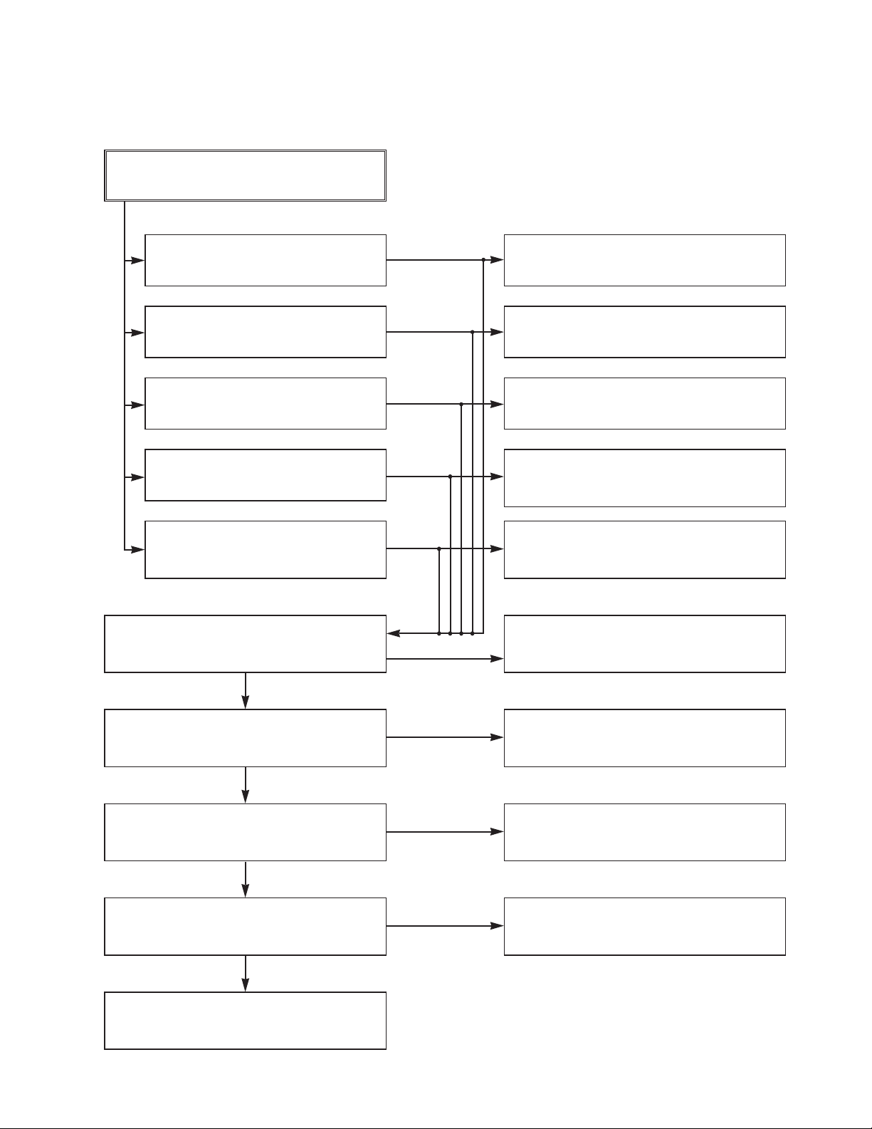
5. Hi-Fi CIRCUIT
(A) No Sound(EE Mode)
No Sound.
YES
Check the TU Audio of IC801
Pins2, 3.
Check the DVD Audio of IC801
Pins4, 5.
Check the AV1 Audio of IC801
Pins6, 7.
Check the AV2 Audio of IC801
Pins8, 9.
Check the AV3 Audio of IC801
Pins10, 11.
Check the Vcc of IC801 Pins34, 40,
IC803 Pin13.
NO
NO
NO
NO
NO
YES
NO
Check the IC751 Pins30, 31.
Check the DVD MODULE.
(PMD02 Pins13, 15).
Check the Scart1 Jack.
(SC901 Scart1 Audio in Pins2, 6).
Check the Scart2 Jack.
(SC901 Scart2 Audio in Pins2, 6).
Check the front Jack.
(L5F1, L5F2).
Check the Power 5.2V, 12VT.
YES
Check the IIC Clock and DATA at
IC801 Pins42, 43.
YES
Check the Audio of IC801 Pins16, 17.
YES
Check the Audio of IC803 Pins3, 5.
YES
Check the JK902.
NO
Check the IC501 Pins59, 60.
NO
Replace IC801.
NO
Replace IC803.
3-15
Page 20
3. Y/C CIRCUIT
(B) Hi-Fi Playback
PB mode
No Sound.
YES
YES
Check the Vcc of IC801
(Pins34, 40)
YES
Check the Hi-Fi Selection switch.
(IC801 Pin41) and the Tape quality.
YES
Is the RF Envelope at
IC801 Pin44 over 2Vp-p?
YES
Check IC801 Pin42(Data),
Pin43(Clock)
YES
Do Audio Signals appear at
IC801 Pin16(L-CH), 17(R-CH)?
YES
Do Audio Signals appear at
IC803 Pin16(L-CH), 11(R-CH)?
YES
NO
NO
NO
NO
NO
NO
Check Power 5.2V, 12VT.
Check IC501 Pin106
(A.H/SW)
Check the parts of µ-COM
(IC501 Pins59, 60)
Check the Connection at
P3D01 Pins7, 9.
Check the A.IN line of
IC803(C837, C838)
Do Audio Signals appear at
IC803 Pins3, 5?
YES YES
Do Audio Signals appear at
JK902?
NO
NO
Check the Vcc of IC803
Pin13.
Replace IC803.
Check the Jack(JK902)
3-16
NO
Check Power.
Page 21

(C)
Hi-Fi REC.
YES
It can’t be recorded Hi-Fi Audio
signal.
YES
Check Vcc of IC801.(Pins34, 40)
YES
Check IC801 Pin42(Data), Pin43(CLOCK).
YES
Do Audio signals appear at IC801
Pins16, 17?
YES
Do FM Audio signals appear at IC801
Pin36?
YES
Check the Contact Point of Drum
Connector if good then Replace the Drum.
NO
NO
NO
NO
Check Power 5V, 12VT.
Check ports of µ-COM.
(IC501 pins 59, 60)
Check Audio input signal of IC801
Pins2, 3(TU.A.), 4, 5(DVD.A.),
6, 7(AVI.A.), 8, 9(AV2.A.), 10, 11(AV3.A.).
Replace IC801.
3-17
Page 22

6. Tuner/IF CIRCUIT
(A) No Picture on the TV screen
No picture on the TV
screen
YES
Does the Video signal at
the TU701 Pin24.
YES
NO
Is +33V applied to TU701
Pin16?
YES
Is +5V applied to TU701
Pin13?
YES
Does the Clock signal
appear at TU701 Pin11?
YES
Does the data signal
appear at TU701 Pin12?
YES
Replace Tuner.
NO
NO
NO
NO
Check 33V line.
Check 5V line.
Check the lIC Clock Signal
of µ-COM Pin59.
Check the lIC Data Signal
of µ-COM Pin60.
Does Sync appear at
IC501 Pin111.
YES
Does the Video signal at
the IC501 Pin19.
YES
Does the Video signal at
the IC301 Pin29.
YES
Does the Video signal at
the IC802 Pin29.
YES
Check the signal flow from
IC803 Pin6 to SC901 Pin19.
NO
NO
NO
NO
Check the signal flow from
TU701 Pin24 to IC301 Pin15.
Check the signal from IC301
Pin65 to IC501 Pin17.
Check the signal from IC501
Pin19 to IC805 Base.
Check the signal from IC501
Pin54 to IC802 Pin7.
3-18
Page 23

(B) No Sound
No Sound.
YES
Check the Vcc of IC751 Pins1, 11, 19,
22, 33.
YES
Check the Tuner SiF signal at IC751
Pin2.
YES
Check the oscillator of IC751 Pins5, 6.
YES
Check the Audio of IC751 Pins30, 31.
YES
Check the Audio of IC801 Pins2, 3.
YES
NO
NO
NO
NO
NO
Check 5.2V Line.
Check the Tuner SIF of TU701 Pin22.
Replace X751
Check the IIC Clock and Data at IC751
Pins12, 13.
Check the signal flow from IC751
Pins30, 31 to IC801 Pins2, 3.
Check the Audio of IC801 Pins16, 17.
YES
Check the Audio of IC803 Pins3, 5.
YES
Check the Signal flow from IC803
Pins3, 5, SC901 Pins1, 3.
NO
NO
3-19
Check the IIC Clock and Data at IC801
Pins42, 43.
Check the signal flow from IC801
Pins16, 17 to IC803 Pins11, 16.
Page 24

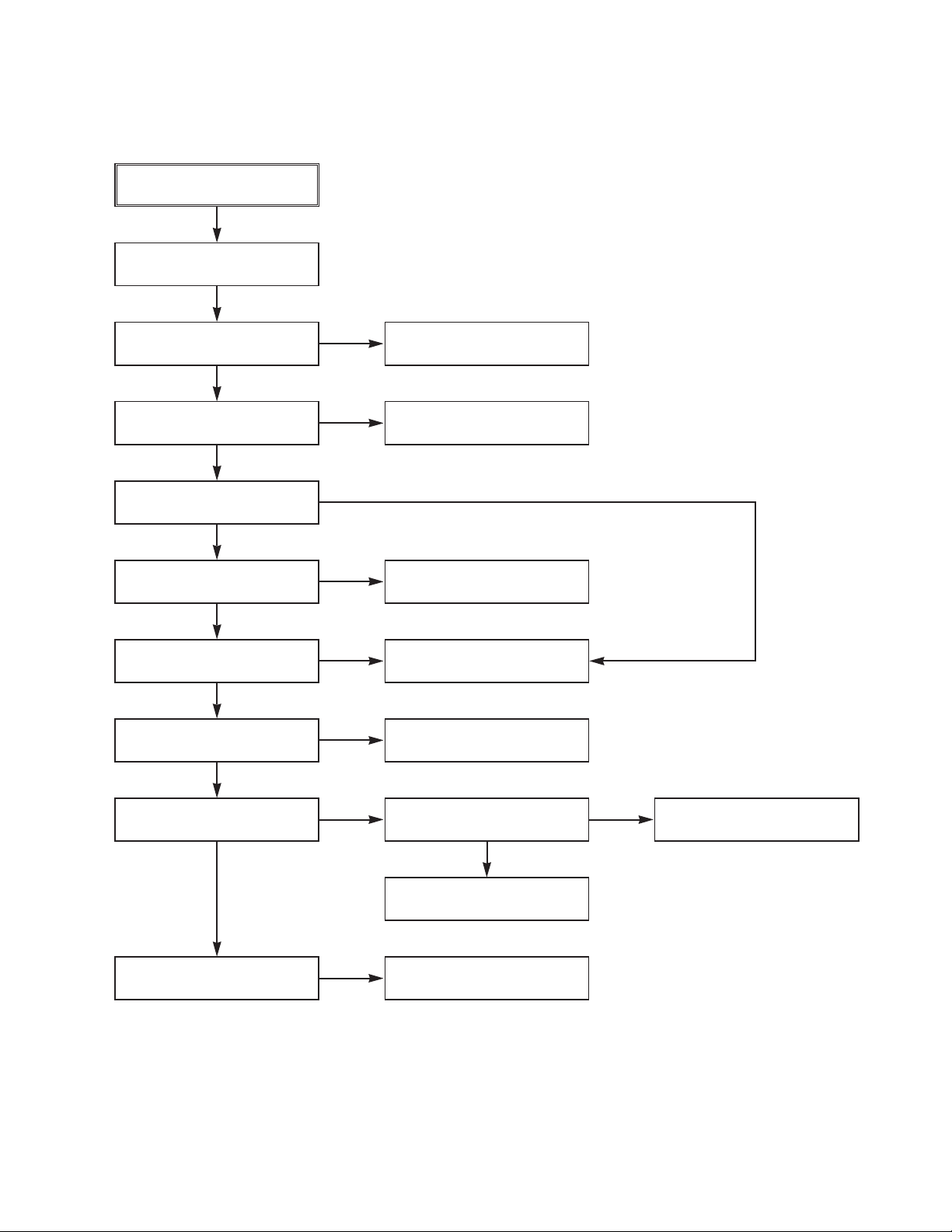
ELECTRICAL TROUBLESHOOTING GUIDE
1. µ-COM Circuit
A. No Power
DVD PART
POWER ON
YES
Does Logo appear
on the screen?
YES
OK
1
YES
Does no DISC appear?
NO
NO
Does Hello
appear at FLD?
NO
Reconnect it.
NO
Is PDV02
connected normally?
Refer to VCR Part
YES
YES
Check power.
(Refer to power)
If power is
normal
Is PDV02 Pins8, 9,
10, 11 normal?
NO
A
1
Is oscillation of
X501 normal?
YES
Are IC501 normal?
YES
A
NO
Check the oscillation
NO
Check short.
Replace IC501
OK
3-52
Check short
Replace IC301.
NONO
NO
The waveform
on AD(0~21) of IC501
normal?
YES
Are IC301 Pins5, 26 normal?
YES
Replace Main B/D.
Page 25

B. Audio abnormal
C. Video abnormal
AUDIO ABNORMAL
Check Audio jack.
YES (If OK)
Check MPEG_CLK Signal
(IC501 Pin22) of MPEG part.
YES (If OK)
Refer to Audio part.
YES (If OK)
Refer to MPEG part.
YES (If OK)
Replace Main B/D.
VIDEO ABNORMAL
Check Video jack.
YES (If OK)
Refer to Video part.
YES (If OK)
Refer to MPEG part.
YES (If OK)
Replace Main B/D.
D. Open/Close abnormal
Check the connection of MD.
YES
OPEN/CLOSE ABNORMAL
connection of PDV02.
NO
Check PMD03 Pins 5, 6.
Refer to SERVO part.
Check Front.
YES (If OK)
Check the
YES
YES
NO
Reconnect it.
3-53
Page 26

E. Picture abnormal
PICTURE ABNORMAL
Check the disc.
Refer to Servo part
Check MPEG_CLK Signal
(IC501 Pin22) of MPEG part
Check DSP
Check MPEG
If OK
YES (If OK)
YES (If OK)
F. Disc Error
YES (If OK)
Replace Main B/D
DISC ERROR
Check Disc
YES (If OK)
Refer to Servo part
YES (If OK)
Replace main B/D
3-54
Page 27

2. MPEG Circuit
Power is on
Does Logo appear
on the screen?
YES
moving picture of the DVD Disc
Does the
play on the screen
normally?
YES
NO
NO
YES
Check power & clock.
YES
Is MPEG data signal normal?
YES
Is error signal normal?
NO
OK
NO
Check CD/DVD DSP output
signal.
OK
Check MPEG Decoder input
signal.
Check CD/DVD DSP output
signal.
OK
Check MPEG Decoder input
signal.
Does the
moving picture of the video
CD play on the screen
normally?
YES
OPTION
_ If included VCD function.
Does the audio sound
output normally?
YES
END
NO
NO
Is MPEG data signal normal?
YES
Is Clock normal?
YES
Does the audio
sound output from MPEG
decoder?
YES
3-55
NO
NO
Check CD/DVD DSP output
signal.
OK
Check MPEG Decoder input
signal.
Check clock signal
Check clock signal
Page 28

3. RF/Servo Circuit
A.
CHECK POINT(General)
Does signal goes
"High" to IC201 Pin186 when the
power is on?
YES
Does signal pulse
input to IC201 Pins53, 54 when
the power is on?
YES
Does
33.8688MHz clock input to
IC201 Pin138?
Is IC201
Pins79, 80, 84, 88 voltage
about 2.2V?
YES
NO
NO
NO NO
NO
Check "2.µ-COM Part".
Does
33.8688MHz clock input
to IC201 Pin59?
YESYES
Replace IC201
(IC206 soldering or IC defect).
Check power circuit.
Replace X201 or IC206
(33MHz clock defect)
END
3-56
Page 29

B.
No disc
Power on.
Does tray open or close?
YES
NO
Check loading Part.
Push Pick-up to inner track to
the end by hand.
Does
PMD03 Pin10 change
high to low?
YES
Pressing
the open/close key
repeatedly, check the voltage of IC2M1
Pins14, 15 change
0V to 5V
YES
Does
the voltage change
at PMD03 Pins7, 8 more than
2V on the basis of
3.8V?
YES
NO
NO
NO
DECK assembly is defective.
(Limit sw)
check µ-COM Part.
Replace IC2M1.
Fig.1. SLED Driver waveform
Does the pick-up
slide inner or outer
track?
YES
Fig.2. Focus Driver waveform
the pick-up lens move up
Slide the pick-up to
Does
and down?
YES
inner track.
END
NO
NO
DECK assembly is defective.
Check SLED Driver output.
IC201 Pin80 IC2M1 Pins28, 29.
Check Focus Driver output.
(IC201 Pin88, IC2M1 Pins37, 38)
3-57
IC201 Pin80 no output : IC201 is defective
IC2M1 Pins26, 27 no output : IC2M1 is defective
IC201 Pin88 no output : IC201 is defective
IC2M1 Pins37, 38 no output : IC2M1 is defective
Page 30

C.
DISC IN
OPEN/CLOSE
FOCUS ON?
YES
NO
Check
the focus error moving the
lens up and down.
(IC2A1 Pin39)
YES
Fig.3. FOCUS ERROR waveform
NO
Check IC2A1 Pins47,50,51,52
in DVD Mode
IC201 no output : Pick-up is defective.
Does the
TTL level change at IC201
Pin121 and 152 moving
the lens?
NO
YES
Replace µ-COM or IC201.
Check IC2M1 Pin21, PMD03
Does the disc turn?
NO
Pin1, 2 turn when the IC2M1
Check IC201 and IC2M1 when PMD03 Pins1, 2 are abnormal
Pin21 is less than 2.2V.
YES
Is OK the track jump.
NO NO
YES YES
Does the screen appear?
NO
Video Part is defective.
Check "5.MPEG Circuit."
Check "7.OSD/Video Circuit."
YES
Replace IC201.
Does the signal
pulse appear at IC201
Pins150, 151?
Replace µ-COM part.
IC2A1 is defective.
END
3-58
Page 31

D.
CHECK A
Fig.5. RF
waveform
Check RF Eye-Pattern.
RF : 1.5-1.6V(TP2A0)
YES
NO
Check IC2A1 Pin3.
No signal: Pick-up is defective
Is the eye-pattern vivid?
YES YES YES
• Check IC201 Pin165.
• Check the clock at the IC201 Pins37, 59.
NO NO NO
• Both are normal : IC201 is defective
Does the
sawtooth waveform emit
at IC2A1 Pin36?
Replace IC201. Check IC201 Pin84.
Does the 1.6V emit?
No signal at IC201 : IC201 is defective
Replace IC2A1.
END
3-59
Page 32

SECTION 4 MECHANISM OF VCR PART
CONTENTS
DECK MECHANISM PARTS
LOCATIONS
• Top View......................................................4-1
• Bottom View ...............................................4-1
DECK MECHANISM
DISASSEMBLY
1. Drum Assembly.........................................4-2
2. Plate Top ...................................................4-4
3. Holder Assembly CST...............................4-4
4. Opener Door .............................................4-4
5. Bracket Assembly L/D Motor.....................4-4
6. Gear Assembly Rack F/L..........................4-4
7. Arm Assembly F/L.....................................4-4
8. Lever Assembly S/W.................................4-4
9. Arm Assembly Cleaner..............................4-5
10.Head F/E...................................................4-5
1 1.Base Assembly A/C Head.........................4-5
12.Brake Assembly T.....................................4-6
13.Brake Assembly RS ..................................4-6
14.Arm Assembly Tension..............................4-6
15.Reel S / Reel T..........................................4-6
16.Base Assembly P4....................................4-7
17.Opener Lid ................................................4-7
18.Arm Assembly Pinch.................................4-7
19.Lever T/up / Arm T/up...............................4-7
20.Belt Capstan/Motor Capstan.....................4-8
21.Lever F/R ..................................................4-8
22.Clutch Assembly D35................................4-8
23. Brake Assembly Capstan.........................4-8
24.Gear Drive/Gear Cam...............................4-9
25.Gear Sector ...............................................4-9
26.Plate Slider ................................................4-9
27.Lever Tension............................................4-9
28.Lever Spring ..............................................4-9
29.Gear Assembly P2/
Gear Assembly P3 ..................................4-10
30.Base Assembly P2/
Base Assembly P3 ..................................4-10
31.Base Loading ..........................................4-11
32.Base Tension...........................................4-11
33.Arm Assembly Idler .................................4-11
DECK MECHANISM ADJUSTMENT
• Tools and Fixtures for Service...............4-12
1. Mechanism Alignment Position Check ....4-13
2. Preparation for Adjustment......................4-14
3. Checking Torque .....................................4-14
4. Guide Roller Height Adjustment ..............4-15
4-1. Preliminary Adjustment....................4-15
4-2. Precise Adjustment..........................4-15
5. Audio/Control (A/C) Head Adjustment ....4-16
5-1. Preliminary Adjustment....................4-16
5-2. Confirmation of Tape Path between
Pinch Roller and Take-up Guide......4-17
5-3. Precise Adjustment(Azimuth Adjustment)
.........................................................4-17
6. X-Value Adjustment.................................4-17
7. Adjustment after Replacing Drum Assembly
(Video Heads).........................................4-18
8. Check the Tape Travel after Reassembling
Deck Mechanism.....................................4-18
8-1. Checking Audio and RF Locking Time
during Playback after CUE or REV
.........................................................4-18
8-2. Checking for Tape Curling or
Jamming ..........................................4-18
MAINTENANCE/INSPECTION
PROCEDURE
1. Check before starting Repairs ................4-19
2. Required Maintenance............................4-20
3. Scheduled Maintenance..........................4-20
4. Supplies Required for Inspection and
Maintenance............................................4-20
5. Maintenance Procedure..........................4-20
5-1. Cleaning ...........................................4-20
5-2. Greasing ..........................................4-21
MECHANISM TROUBLESHOOTING
GUIDE
1. Deck Mechanism.....................................4-23
2. Front Loading Mechanism.......................4-26
EXPLODED VIEWS
1. Front Loading Mechanism Section .........4-28
2. Moving Mechanism Section (1)...............4-29
3. Moving Mechanism Section (2)...............4-30
Page 33

DECK MECHANISM PARTS LOCATIONS
• Top View
2
7
10
1
31
14
15
8
• Bottom View
20
24
23
20
24
22
21
Procedure
Starting
No.
2 3 Holder Assembly CST Chassis Hole A-2 T
2 4 Opener Door Chassis Hole A-2 T
6
3
4
9
5
11
18
16
17
19
19
12
33
13
15
30
29
29
30
25
32
27
26
28
2,3,4 6 Gear Assembly Rack F/L 1 Hook, Chassis Hole A-2 T
2,3,4,6 7 Arm Assembly F/L Chassis Hole A-2 T
2,3 12 Brake Assembly T 1 Hook A-4 T
2,3 13 Brake Assembly RS 1 Hook A-4 T
2,3 14 Arm Assembly Tension 2 Hook A-4 T
2,3,12,13, 15 Reel S/Reel T A-4 T
14
17 18 Arm Assembly Pinch Shaft A-5 T
17 19 Lever T/Up / Arm T/Up 1 Hook A-5 T
17,18 20
20, 21 22 Clutch Assembly D35 Washer A-6 B
20,21,23, 26 Plate Slider Shaft Guide A-7 B
24,25
20,21,23, 27 Lever Tension 1 Hook A-7 B
24,25,26
2,3,14,20, 28 Lever Spring Locking Tab A7 B
21,25,23,
24,26
25 29
2,3,14,25, 30
29
2,3,14,25, 31 Base Loading 1 Screw A-9 T
29
2,3,14 32 Base Tension Chassis Embossing A-9 B
2,3,20,21, 33 Arm Assembly Idler Locking Tab A-9 T
22
1 Drum Assembly 3 Screw A-1 T
2 Plate Top 2 Hook A-2 T
5 Bracket Assembly 3 Hook A-2 T
L/D Motor
8 Lever Assembly S/W 1 Hook A-2 T
9 Arm Assembly Cleaner Chassis Embossing A-3 T
10 Head F/E Chassis Embossing A-3 T
11 Base Assembly A/C Head 1 Screw A-3 T
16 Base Assembly P4 Chassis Embossing A-5 T
17 Opener Lid Chassis Embossing A-5 T
Belt Capstan/Motor Capstan
21 Lever F/R Locking Tab A-6 B
23 Brake Assembly Capstan Locking T ab A-6 B
24 Gear Drive/Gear Cam Washer/Hook A-7 B
25 Gear Sector 1 Hook A-7 B
Gear Assembly P2/Gear Assembly P3
Base Assembly P2/Base Assembly P3
Part Fixing Type
3 Screw A-6 B
Boss A-8 B
Chassis Slot A-8 B
Fig-
ure
View
NOTE : When reassembly perform the
procedure in the reverse order.
1) When reassembling, confirm Mechanism and Mode
Switch Alignment Position (Refer to Page 4-13)
2) When disassembling, the Parts for Starting No. Should
be removed first.
T:Top, B:Bottom
4-1
Page 34

DECK MECHANISM DISASSEMBLY
Carbon Brush
(S3)
(S2)
(S2)
(A)
(S3)
Stator
Drum Motor
Rotor
Drum Sub Assembly
(Fig. A-1-1)
Drum FPC
Fig. A-1
1. Drum Assembly (Fig. A-1-1)
1) Unplug the Drum FPC Connector.
2) Remove three Screws(S1) on bottom side and separate
the Drum assembly.
3) Unhook (H1), (H2) and separate the Holder FPC and
Cap FPC.
1-1. Drum Motor
1) Remove two Screws(S2) and disassemble the Stator of
the Drum Motor.
2) Remove two Screws(S3) and separate the Rotor of the
Drum Motor from the Drum Sub assembly.
NOTE
When reassembling, confirm (A) portion of the Drum Sub
assembly whether the Carbon Brush is in there or not.
(S1)
(S1)
(S1)
H2
H1
Holder FPC
(Fig. B-1)
Cap FPC
Drum FPC
Holder FPC
Figure in the opposite direction
4-2
Page 35

DECK MECHANISM DISASSEMBLY
(B')
Plate Top
Arm Assembly F/L
Lever Assembly S/W
(Fig. A-2-1)
(Fig. A-2-6)
(Fig. A-2-7)
(B)
(C)
Holder Assembly CST
(E)
(C1)
(Fig. A-2-2)
(H8)
Spring Lever S/W
(D)
Bracket Assembly L/D Motor
(Fig. A-2-4)
Chassis
Fig. A-2
(C')
(E')
Gear Assembly Rack F/L
(Fig. A-2-5)
Opener Door
(Fig. A-2-3)
(H6)
(A)
(B)
4-3
Page 36

DECK MECHANISM DISASSEMBLY
2. Plate Top (Fig. A-2-1)
1) Pull the (B) portion of the Plate Top back in direction of
arrow and separate the right side of it.
2) pull the (B’) portion of the Plate Top back in direction of
arrow and separate the left side of it.
(Used tools : (-) type driver, anything tool with sharp
point or flat point.)
NOTE
(1) When reassembling, push the Plate Top after alignment
the two position(C), (C’) as below Fig.
(C')
(C)
(B')
(B)
3. Holder Assembly CST (Fig.A-2-2)
1) Move the Holder Assembly CST in direction of arrow and
separate the left side of it first through the (D) position of
the Chassis.
2) Unhook three Hooks(H3, H4, H5) on bottom side of the
Chassis, lift up the Bracket Assembly L/M and disassemble the Bracket Assembly L/D Motor.
(H4)
(H3)
(H5)
Bracket assembly L/M
6. Gear Assembly Rack F/L (Fig. A-2-5)
1) Move the Gear Assembly Rack F/L in direction of
arrow(A) and unhook the Hook(H6) pulling back in front.
2) Separate the Gear Rack F/L in direction of arrow(B).
NOTE
When reassembling, align the gear part of the Gear
Assembly Rack F/L with the Gear Drive as below Fig.
Gear Rack F/L
Holder assembly CST
(D)
Chassis
2) Disassemble the right side of the Holder Assembly CST
from each guided hole of the Chassis.
NOTE
When reassembling, insert the (E) part of the Holder
Assembly CST in the (E’) hole of the Chassis first and
assemble the left side of it.
4. Opener Door (Figure. A-2-3)
1) Turn the Opener Door clockwise and remove it through
the guide hole of the Chassis.
5. Bracket Assembly L/D Motor (Fig. A-2-4)
1) Unplug the Connector(C1).
Gear Drive
7. Arm Assembly F/L (Fig. A-2-6)
1) Move the Arm Assembly F/L in direction of arrow and
separate the left side of it first.
2) Disassemble the Arm Assembly F/L from each guided
hole of the Chassis.
8. Lever Assembly S/W(Fig. A-2-7)
1) Unhook the Hook(H8) in the left side of the Chassis and
remove the Lever Assembly S/W.
Chassis
(H8)
4-4
Page 37

DECK MECHANISM DISASSEMBLY
Arm Assembly
Cleaner
(Fig. A-3-1)
(A)
(S4)
Head F/E
(Fig. A-3-2)
(A)
Base Assembly A/C Head
(Fig. A-3-3)
Chassis
Fig. A-3
9. Arm Assembly Cleaner (Fig. A-3-1)
1) Breakaway the (A) portion as Fig. A-3-1 from the
embossing of the Chassis, turn the Arm assembly
Cleaner to clockwise direction and lift it up.
10. Head F/E (Fig. A-3-2)
1) Breakaway the (A) portion of the Head F/E from the
embossing of the Chassis, turn it to counterclockwise
direction and lift it up.
11. Base Assembly A/C Head (Fig. A-3-3)
1) Remove the Screw(S4) and lift the Base Assembly A/C
Head up.
4-5
Page 38

DECK MECHANISM DISASSEMBLY
Arm Assembly Tension
(Fig. A-4-3)
(H11)
Spring Tension
Reel S
(Fig. A-4-4)
Spring TB
Brake Assembly T
(Fig. A-4-1)
Reel T
(Fig. A-4-4)
Spring RS
Brake Assembly RS
(Fig. A-4-2)
(H12)
Base Tension
Chassis
Fig. A-4
12. Brake Assembly T (Fig. A-4-1)
1) Unhook the Spring TB from the Hook(H9) of the Chassis.
2) Lift the Brake Assembly T up.
13. Brake Assembly RS (Fig. A-4-2)
1) Unhook the Spring RS from the Hook(H10) of the
Chassis.
2) Lift the Brake Assembly T up.
14. Arm Assembly Tension (Fig. A-4-3)
1) Unhook the Spring Tension from the Hook(H11) of the
Arm Assembly Tension.
2) Unhook the Hook(H12) of the Base Tension and lift the
Arm Assembly Tension up.
(H9)
(H10)
NOTE
Difference for Springs
Spring TB
Spring RS
Color (Black)
Spring Tension
15. Reel S / Reel T (Fig. A-4-4)
1) Difference for Reel S / Reel T
4-6
Reel S R eel T
Page 39

DECK MECHANISM DISASSEMBLY
(B)
Opener Lid
(Fig. A-5-2)
Base Assembly P4
(Fig. A-5-1)
(A)
(B)
Arm
Assembly
Pinch
(Fig. A-5-3)
(C)
(C)
Arm T/up
(Fig. A-5-5)
Lever T/up
(Fig. A-5-4)
(H13)
Chassis
(H13)
Fig. A-5
16. Base Assembly P4 (Fig. A-5-1)
1) Breakaway the (A) portion of the Base Assembly P4 from
the embossing of the Chassis.
2) Turn the Base Assembly P4 to counterclockwise direction
and lift it up.
17. Opener Lid (Fig. A-5-2)
1) Breakaway the (B) portion of the Opener Lid from the
embossing of the Chassis.
2) Turn the Opener Lid to clockwise direction and lift it up.
18. Arm Assembly Pinch (Fig. A-5-3)
1) Lift the Arm Assembly Pinch up.
NOTE
When reassembling, confirm the (C) portion of the Arm
Assembly Pinch is inserted to the Chassis hole correctly as
Fig.
19. Lever T/up (Fig. A-5-4)/
Arm T/up (Fig. A-5-5)
1) Unhook the Hook(H13) of the bottom Chassis and lift the
Lever T/up up.
2) Lift the Arm T/up up.
4-7
Page 40

DECK MECHANISM DISASSEMBLY
Belt Capstan
(Fig. A-6-1)
Motor Capstan
(Fig. A-6-2)
Brake Assembly Capstan
(L1)
(Fig. A-6-5)
(Fig. A-6-3)
(L2)
(L1)
Lever F/R
Washer(W1)
Clutch Assembly D35
(Fig. A-6-4)
(S5)
Fig. A-6
20. Belt Capstan (Fig. A-6-1)/
Motor Capstan (Fig. A-6-2)
1) Remove the Belt Capstan.
2) Remove the three Screws(S5) on bottom Chassis and lift
the Motor Capstan up.
21. Lever F/R (Fig. A-6-3)
1) Unlock the Locking Tab(L1) as Fig. A-6-3 and lift the
Lever F/R up.
Chassis
22. Clutch Assembly D35 (Fig. A-6-4)
1) Remove the Washer(W1) and lift the Clutch Assembly
D35 up.
23. Brake Assembly Capstan
(Fig. A-6-5)
1) Pull the Locking Tab(L2) back in direction of arrow and lift
it up.
4-8
Page 41

DECK MECHANISM DISASSEMBLY
(H14)
Gear Cam Hole(B)
Gear Drive Hole(C)
Gear Drive Hole(A)
Gear Cam
(Fig. A-7-2)
Washer (W2)
Gear Drive
(Fig. A-7-1)
(H15)
(H16)
(A)
(L3)
Gear Sector
(Fig. A-7-3)
Plate Slider
(Fig. A-7-4)
Lever Tension
(Fig. A-7-5)
Lever spring
(Fig. A-7-6)
Base Loading
Fig. A-7
24. Gear Drive (Fig. A-7-1)/
Gear Cam (Fig. A-7-2)
1) Remove the Washer(W2) and lift the Gear Drive up.
2) Unhook the Hook(H14) of the Gear Cam and lift the Gear
Cam up.
NOTE
When reassembling, align the Gear Drive Hole(A) and the
Gear Cam Hole(B) in a straight line after the Gear Drive
Hole(C) is aligned with the Chassis Hole as Fig.
25. Gear Sector (Fig. A-7-3)
1) Unhook the Hook(H15) of the Base Loading on bottom
Chassis and lift the Gear Sector up.
Chassis
26. Plate Slider (Fig. A-7-4)
1) Just lift the Plate Slider up.
27. Lever Tension (Fig. A-7-5)
1) Unhook the (A) portion of the Lever Tension from the
Hook(H16) of the Chassis.
2) Turn the Lever Tension to counterclockwise direction and
lift it up.
28. Lever Spring (Fig. A-7-6)
1) Unlock the Locking Tab(L3) of the bottom Chassis and lift
the Lever Spring up.
4-9
Page 42

DECK MECHANISM DISASSEMBLY
Gear Assembly P2 Hole
Gear Assembly P3 Hole
Gear Assembly P3
(Fig. A-8-2)
Lever Spring Boss
Gear Sector Hole(A)
Plate Slider Hole(B)
(B)
Chassis
Base Assembly P3
(Fig. A-8-4)
Fig. A-8
Gear Assembly P2
(Fig. A-8-1)
(A)
Base Assembly P2
(Fig. A-8-3)
29. Gear Assembly P2 (Fig. A-8-1)/
Gear Assembly P3 (Fig. A-8-2)
1) Just lift the Gear Assembly P2 up.
2) Just lift the Gear Assembly P3 up.
NOTE
When reassembling, align the two holes of the Gear
Assembly P2 and P3 in a straight line after confirmation
whether the Gear Sector Hole(A) and the Plate Slider
Hole(B) are aligned or not as Fig.
30. Base Assembly P2 (Fig. A-8-3)/
Base Assembly P3 (Fig. A-8-4)
1) Move the Base Assembly P2 in direction of arrow(A)
along the guide hole of the Chassis and disassemble it
on bottom side.
2) Move the Base Assembly P3 in direction of arrow(B)
along the guide hole of the Chassis and disassemble it
on bottom side.
4-10
Page 43

DECK MECHANISM DISASSEMBLY
Base Tension
(Fig. A-9-2)
(A)
(S7)
Base Loading
(Fig. A-9-1)
(B) (C)
Arm Assembly Idler
(Fig. A-9-3)
(D)
Fig. A-9
31. Base Loading (Fig. A-9-1)
1) Remove the Screw(S7).
2) Lift the Base Loading up.
32. Base Tension (Fig. A-9-2)
1) Breakaway the (A) portion of the Base Tension from the
embossing of the Chassis.
2) Turn the Base Tension to counterclockwise direction and
lift it up.
Chassis
33. Arm Assembly Idler (Fig. A-9-3)
1) Make narrower the two parts, (B) and (C), as Fig. A-9-3.
2) Lift the Arm assembly Idler up.
NOTE
When disassembling, be careful not to be caught the (D) part
by the Chassis as Fig.
4-11
Page 44

DECK MECHANISM ADJUSTMENT
• Tools and Fixfures for Service
1. Cassette Torque Meter
1. PUJ42881
1.
300
S
-
T
250
H
V
-
200
K
R
150
S
SRK
VIDEO
CASSETTE
H
V
T
-
-
K
T
R
0
TORQUE
S
50
0
METER
VHT-303
50
100
150
200
250
300
5. Post Height Adjusting Driver
(Roller driver)
PTU94002
2. Alignment Tape
NTSC: MHP
PAL: MHPE
3. Torque Gauge
3. PUJ48075-2
4-12
Page 45

DECK MECHANISM ADJUSTMENT
1. Mechanism Alignment Position Check
Purpose:To determine if the Mechanism is in the correct position, when a Tape is ejected.
Test Equipment/ Fixture
• Blank tape
1) Turn the Power S/W on and eject the Cassette by pressing the Eject Button.
2) Remove the Top Cover and Plate Assembly Top, visually check if the Gear Cam Hole is aligned with the
Chassis Hole as below Fig. C-2.
3) IF not, rotate the Shaft of the Loading Motor to either
clockwise or counterclockwise until the alignment is as
below Fig. C-2.
Test Conditions (Mechanism
Condition)
• Eject Mode (with Cassette ejected)
CHECK DIAGRAM
Check Point
• Mechanism and Mode Switch Position
4) Remove the Screw which fixes the Deck Mechanism and
Main Frame and confirm if the Gear Cam is aligned with
the Gear Drive as below Fig. C-1(A).
5) Confirm if the Mode S/W on the Main P.C.Board is
aligned as below Fig. C-1(B).
6) Remount the Deck Mechanism on the Main P.C.Board
and check each operation.
Gear Cam
(A)
(B)
Mode S/W
BOTTOM VIEW
TOP VIEW
L/D Motor Assembly
(A')
(B')
Fig. C-1
Gear Cam
Chassis Hole
Fig. C-2
Gear Drive
Gear Cam (o) and Gear Drive (o) groove alignment
(A)
Gear Cam Hole
Gear Drive Hole
(B)
4-13
Page 46

DECK MECHANISM ADJUSTMENT
2. Preparation for Adjustment (To set the
Deck Mechanism of the loading state
without inserting a cassette tape).
1) Unplug the power cord from the AC outlet.
2) Disassemble the Top Cover and Plate Assembly Top.
3) Plug the power cord into the AC outlet.
4) Turn the power S/W on and push the Lever Stopper of
the Holder Assembly CST to the back for loading the
cassette without tape.
Cover the holes of the End Sensors at the both sides of
the Chassis to prevent a light leak.
Then the Deck Mechanism drives to the Stop Mode.
In this case, the Deck Mechanism can accept inputs of
each mode, however the Rewind and Review operation
can not be performed for more than a few seconds
because the Take-up Reel Table is in the Stop State
and can not be detected the Reel Pulses.
3. Checking Torque
Purpose: To insure smooth transport of the tape during each mode of operation.
If the tape transport is abnormal, then check the torque as indicated by the chart below.
Test Equipment/ Fixture
• Torque Gauge(600g/cm ATG)
• Torque Gauge Adaptor
• Cassette Torque Meter
Item
• Play (FF) or Review (REW) Mode
Mode
Test Conditions
(Mechanism Condition)
Test Equipment
Checking Method
• Perform each Deck Mechanism mode without
inserting a cassette tape(Refer to above No.2
Preparation for Adjustment).
• Read the measurement of the Take-up or Supply
Reels on the Cassette Torque Meter(Fig. C-3-2).
• Attach the Torque Gauge Adaptor to the Torque
Gauge and then read the value of it(Fig. C-3-1).
Measurement Reel
Measurement Values
Fast Forward Torque
Rewind Torque
Play Take-Up Torque
Review Torque
Fast Forward
Rewind
Play
Review
Cassette Torque Gauge
Cassette Torque Gauge
Cassette Torque Meter
Cassette Torque Meter
NOTE:
The values are measured by using a Torque Gauge and
Torque Gauge Adaptor with the Torque Gauge affixed.
Torque Gauge
Torque Gauge
Adaptor
Reel Table
Take-Up Reel
Supply Reel
Take-Up Reel
Supply Reel
More than 400g/cm
More than 400g/cm
40~100g/cm
120~210g/cm
NOTE:
The torque reading to measure occurs when the tape
abruptly changes direction from Fast Forward to Rewind
Mode, when quick braking is applied to both Reels.
• Cassette Torque Meter • Torque Gauge (600g.cm ATG)
300
S
-
T
250
H
V
-
K
R
S
200
150
SRK
VIDEO
CASSETTE
TORQUE
50
0
METER
VHT-303
H
V
T
-
-
K
T
R
0
S
50
100
150
200
250
300
4-14
Fig. C-3-2Fig. C-3-1
Page 47

DECK MECHANISM ADJUSTMENT
4.Guide Roller Height Adjustment
Purpose: To regulate the height of the tape so that the bottom of the tape runs along the
tape guide line on the Lower Drum.
4-1. Preliminary Adjustment
Test Equipment/ Fixture
• Post Height Adjusting Driver
Test Conditions (Mechanism Condition)
• Play or Review Mode
Adjustment Procedure
1) Confirm if the tape runs along the tape guide line of the
Lower Drum.
2) If the tape runs the bottom of the guide line, turn the
Guide Roller Height Adjustment Screw to clockwise
direction.
3) If it runs the top, turn to counterclockwise direction.
4) Adjust the height of the Guide Roller to be guided to the
guide line of the Lower Drum from the starting and ending point of the Drum.
4-2. Precise Adjustment
Test Equipment/Fixture
• Oscilloscope
• Alignment T ape
• Post Height Adjusting
Driver
Test Equipment Connection Points
• CH-1:PB RF Envelope
• CH-2:NTSC: SW 30Hz
PAL: SW 25Hz
• Head Switching Output
Point
• RF Envelope Output
Point
Adjustment Point
• Guide Roller Height Adjustment
screws on the Supply and Take-Up
Guide Rollers.
ADJUSTMENT DIAGRAM
Fig. C-4-1
Test Conditions VCR(VCP) State
• Play an Alignment Tape
• Guide Roller Height
Adjustment Screws
Waveform Diagrams
P2 POST
ADJUSTMENT
Guide Roller Height
Adjustment screw
Upper Flange
Guide Roller
Retaining Screw
Adjustment Point
Adjustment Procedure
1) Play an Alignment Tape after connecting the probe of the
Oscilloscope to the RF Envelope Output Test Point and
Head Switching Output Test Point.
2) Tracking Control(in PB Mode) : Center Position(When
this adjustment is performed after the Drum Assembly
has been replaced, set the Tracking Control so that the
RF Output is Maximum).
3) Height Adjustment Screw : Flatten the RF waveform.
(Fig. C-4-2)
4) Turn(Move) the Tracking Control(in PB Mode) clockwise
and counterclockwise.(Fig. C-4-3)
5) Check that any drop of RF Output is uniform at the start
and end of the waveform.
NOTE
If the adjustment is excessive or insufficient the tape will
jam or fold.
P3 POST
ADJUSTMENT
Tracking Control at center
Connection Diagram
RF ENVELOPE OUTPUT TEST POINT
HEAD SWITCHING OUTPUT TEST
POINT
4-15
Turn the Roller Guide Height
Adjustment Screw slightly
to flatten the waveform.
Fig. C-4-2
Turn(Move) the Tracking
Control to both directions
Fig. C-4-3
OSCILLOSCOPE
Page 48

DECK MECHANISM ADJUSTMENT
5. Audio/Control (A/C) Head Adjustment
Purpose: To insure that the tape passes accurately over the Audio and Control Tracks in
exact alignment of the both Record and Playback Modes.
5-1. Preliminary Adjustment (Height and Tilt Adjustment)
Perform the Preliminary Adjustment, when there is no Audio Output Signal with the Alignment Tape.
Test Equipment/ Fixture
• Blank Tape
• Screw Driver(+) Type 5mm
Test Conditions (Mechanism Condition)
• Play the blank tape
Adjustment Procedure/Diagrams
1) Initially adjust the Base Assembly A/C Head as shown
Fig. C-5-1 by using the Height Adjustment Screw(B).
2) Play a blank tape and observe if the tape passes accurately over the A/C Head without tape curling or folding.
3) If folding or curling is occured then adjust the Tilt
Adjustment Screw(C) while the tape is running to resemble Fig. C-5-3.
10.9
Adjustment Point
• Tilt Adjustment Screw(C)
• Height Adjustment Screw(B)
• Azimuth Adjustment Screw(A)
4) Reconfirm the tape path after Playback about 4~5 seconds.
NOTE
Ideal A/C head height occurs when the tape runs between
0.2~0.25mm above the bottom edge of the A/C Head core.
A/C Head
P4
Tape
0.2~0.25mm
Tape
X-Value Adjustment
Hole
Fixed Screw
Azimuth Adjustment
Screw(A)
A/C Head Assembly
A/C Head Base
Fig. C-5-1
Fig. C-5-2
Fig. C-5-3
Tilt Adjustment
Screw(C)
Height Adjustment
Screw(B)
4-16
Page 49

DECK MECHANISM ADJUSTMENT
5-2. Confirm that the tape passes smoothly
between the Take-up Guide and Pinch
Roller(using a mirror or the naked eye).
1) After completing Step 5-1.(Preliminary Adjustment), check
that the tape passes around the Take-up Guide and Pinch
Roller without folding or curling at the top or bottom.
(1) If folding or curling is observed at the bottom of the
Take-up Guide then slowly turn the Tilt Adjustment
Screw(C) in the clockwise direction.
5-3. Precise Adjustment (Azimuth adjustment)
Test Equipment/ Fixture
• Oscilloscope
• Alignment T ape(SP)
• Screw Driver(+) Type 5mm
Connection Point
• Audio output jack
Adjustment Procedure
1) Connect the probe of the oscilloscope to Audio Output
Jack.
2) Alternately adjust the Azimuth Adjustment Screw(A) and
the Tilt Adjustment Screw(C) for maximum output of the
1KHz and 7KHz segments, while maintaining the flattest
envelope differential between the two frequencies.
(2) If folding or curling is observed at the top of it then
slowly turn the Tilt Adjustment Screw(C) in the
counterclockwise direction.
NOTE:
Check the RF envelope after adjusting the A/C Head, if the
RF waveform differs from Fig. C-5-4, performs Precise
Adjustment to flat the RF waveform.
Test Conditions
(Mechanism Condition)
• Play an Alignment Tape
1KHz, 7KHz Sections
1KHZ
A:Maximum
Adjustment Point
• Azimuth Adjustment Screw(A)
• Height Adjustment Screw(B)
7KHZ
B:Maximum
Fig. C-5-4
6. X-Value Adjustment
Purpose: To obtain compatibility with the other VCR(VCP) Models.
Test Conditions
(Mechanism Condition)
• Oscilloscope
• Alignment T ape(SP only)
• Screw Driver(+) Type 5mm
• CH-1: PB RF Envelope
• CH-2: NTSC: SW 30Hz
PAL: SW 25Hz
• Head Switching Output
Test Point
• RF Envelope Output Test
Point
Adjustment Procedure
1) Release the Automatic Tracking to run long enough for
tracking to complete it’s cycle.
2) Loosen the Fixed Mounting Screw and move the Base
Assembly A/C Head in the direction as shown in the diagram to find the center of the peak that allows for the maximum waveform envelope.
This method should allow the 31µm Head to be centrally
located over the 58µm tape track.
3) Tighten the Base Assembly A/C Head mounting Screw.
• Play an Alignment Tape
Adjustment Diagram
X-Value Adjustment Hole
Fixed Screw
Azimuth Adjustment
Screw(A)
Connection Diagram
RF ENVELOPE OUTPUT TEST POINT
HEAD SWITCHING OUTPUT TEST POINT
Adjustment PointConnection PointTest Equipment/ Fixture
Groove at the
Left
Height Adjustment Screw(B)
Base A/C
Right
Tilt Adjustment Screw(C)
OSCILLOSCOPE
CH-1
CH-2
4-17
Page 50

DECK MECHANISM ADJUSTMENT
7. Adjustment after Replacing Drum Assembly (Video Heads)
Purpose: To correct for shift in the Roller Guide and X value after replacing the Drum.
Test Equipment/ Fixture
• Oscilloscope
• Alignment T apes
• Blank Tape
• Post Height Adjusting Driver
• Screw Driver(+) Type 5mm
Connection Point
• CH-1: PB RF Envelope
• CH-2: NTSC: SW 30Hz
PAL: SW 25Hz
• Head Switching Output
Test Point
Test Conditions
(Mechanism Condition)
• Play the Blank Tape
• Play an Alignment Tape
Adjustment Points
• Guide Roller Precise
Adjustment
• Switching Point
• Tracking Preset
• X-Value
• RF Envelope Output Test Point
Checking/Adjustment Procedure
Connection Diagram
Play a blank tape and check for tape curling or creasing around
the Roller Guide. If there is a problem then follow the procedure
4. "Guide Roller Height" and 5. "Audio Control(A/C) Head
Adjustment".
RF ENVELOPE OUTPUT TEST POINT
HEAD SWITCHING OUTPUT TEST
POINT
Waveform
V1/V MAX 0.7
V2/V MAX 0.8
RF ENVELOPE OUTPUT
<
=
<
=
V1
V
V2
Fig. C-7
8. Check the Tape Travel after Reassembling Deck Assembly.
8-1. Checking Audio and RF Locking Time during playback and after CUE or REV (FF/REW)
Test Equipment/ Fixture
• Oscilloscope
• Alignment T apes(with 6H
3KHz Color Bar Signal)
• Stop Watch
Specification
• RF Locking Time: Less than 5
sec.
• Audio Locking Time:Less than
10sec
Test Equipment
Connection Points
Connection Points
• CH-1: PB RF Envelope
• CH-2: Audio Output
• RF Envelope Output Point
• Audio Output Jack
Test Conditions
(Mechanism Condition)
• Play an Alignment Tape
(with 6H 3kHz Color Bar
Signal)
OSCILLOSCOPE
CH1 CH2
Checking Procedure
Play an Alignment Tape then change the operating mode to
CUE or REV and confirm if the unit meets the above listed
specifications.
8-2. Checking for tape curling or jamming
Test Equipment/ Fixture
• T-160 Tape
• T-120 Tape
• Be sure there is no tape jamming or curling at
the begining, middle or end of the tape.
Specification
Checking Procedure
1) Confirm that the tape runs smoothly around the roller
guides, Drum and A/C Head Assemblies while abruptly
changing operating modes from Play to CUE or REV.
This is to be checked at the begining, middle and end
sections of the tape.
NOTES:
1) CUE is the forward search mode
2) REV is the backward search mode
3) Refer to the Play mede
Test Conditions (Mechanism Condition)
•
Run the CUE, REV, Play mode at the
VCR(VCP) State
beginning and the end of the tape.
2) Confirm that the tape passes over the A/C Head
Assembly as indicated by proper audio reproduction and
proper tape counter performance.
4-18
Page 51

MAINTENANCE/INSPECTION PROCEDURE
1. Check before starting repairs
The following faults can be remedied by cleaning and oiling. Check the needed lubrication and the conditions of
cleanliness in the unit.
Check with the customer to find out how often the unit is
used, and then determine that the unit is ready for inspection and maintenance. Check the following parts.
Phenomenon Inspection
Color beats Dirt on Full-Erase Head
Poor S/N, no color Dirt on Video Head
Vertical or
Horizontal jitter
Low volume,
Sound distorted
Tape does not run.
Tape is slack
In Review and
Unloading (off mode),
the tape is rolled up
loosely.
Dirt on Video Head
Dirt on tape transport system
Dirt on Audio/Control Head
Dirt on Pinch Roller
Clutch Assembly D35
torque reduced
Cleaning Drum and
transport system
Replace-
ment
o
o
o
o
o
o
Fig. C-9-3
NOTE
If locations marked with o do not operate normally after
cleaning, check for wear and replace.
See the EXPLODED VIEWS at the end of this manual as
well as the above illustrations and see the Greasing (Page
4-21, 22) for the sections to be lubricated and greased.
F/E Head
Video Head
A/C Head
Pinch Roller
Belt Capston
Clutch
Assembly D35
Fig. C-9-1 Top View
Fig. C-9-2 Bottom View
* No. (1)~(12) Indicates the Tape Path to be traveled from Supply Reel to Take-up Reel.
(3) F/E Head
(5) Drum Assembly
(Video Head)
(4) Base
Assembly P2
(2) Tension Post
(1) Supply Reel
(6) Base Assembly P3
(7) A/C Head
(8) P4 Post
(10) Pinch Roller
(11) T ake-up Guide Post
(9) Capstan Shaft
(12) Take-up Reel
Fig. C-9-3 Tape Transport System
4-19
Page 52

MAINTENANCE/INSPECTION PROCEDURE
2. Required Maintenance
The recording density of a VCR(VCP) is much higher than
that of an audio tape recorder. VCR(VCP) components must
be very precise, at tolerances of 1/1000mm, to ensure compatibility with the other VCRs. If any of these components are
worn or dirty, the symptoms will be the same as if the part is
defective. To ensure a good picture, periodic inspection and
maintenance, including replacement of worn out parts and
lubrication, is necessary.
3. Scheduled Maintenance
Schedules for maintenance and inspection are not fixed
because they vary greatly according to the way in which the
customer uses the VCR(VCP), and the environment in which
the VCR(VCP) is used.
But, in general home use, a good picture will be maintained
if inspection and maintenance is made every 1,000 hours.
The table below shows the relation between time used and
inspection period.
Table 1
When
inspection is
necessary
Average
hours used
per day
About 1
year
About 18
months
About 3
years
4. Supplies Required for Inspection and Maintence
(1) Grease : Kanto G-311G (Blue) or equivalent
(2) Isopropyl Alcohol or equivalent
(3) Cleaning Patches
(4) Grease : Kanto G-381(Yellow)
5. Maintenance Procedure
5-1) Cleaning
(1) Cleaning video head
First use a cleaning tape. If the dirt on the head is too
stubborn to remove by tape, use the cleaning patch. Coat
the cleaning patch with Isopropyl Alcohol. Touch the
cleaning patch to the head tip and gently turn the
head(rotating cylinder) right and left.
(Do not move the cleaning patch vertically. Make sure
that only the buckskin on the cleaning patch comes into
contact with the head. Otherwise, the head may be damaged.)
Thoroughly dry the head. Then run the test tape. If lsopropyl Alcohol remains on the video head, the tape may
be damaged when it comes into contact with the head
surface.
(2) Clean the tape transport system and drive system, etc, by
wiping with a cleaning patch wetted with Isopropyl
Alcohol.
One hour
Two hours
Three hours
Cleaning Patch
Coat With Isopropyl Alcohol
NOTES:
1 It is the tape transport system which comes into contact
with the running tape. The drive system consists of those
parts which moves the tape.
2 Make sure that during cleaning you do not touch the tape
transport system with excessive force that would cause
deformation or damage to the system.
Drum
(Rotating Cylinder)
Head Tip
Touch this section of cleaning
patch to the head tip and gently
turn the Drum (Rotating Cylinder)
Fig. C-9-4
4-20
Page 53

MAINTENANCE/INSPECTION PROCEDURE
5-2) Greasing
(1) Greasing guidelines
Apply grease, with a cleaning patch. Do not use excessive grease. It may come into contact with the tape
transport or drive system. Wipe excessive grease and
clean with cleaning patch wetted in Isopropyl Alcohol.
NOTE:Greasing Points
1)Loading Path Inside & Top side
2)Base Assembly P2, P3 stopper
3) Shaft
4) L/D Motor Gear Wheel Part
2
1
7
Chassis (Top)
5)Arm Take-up Rubbing Sections
6)Reel S,T shaft(G381:Yellow)
7)Arm Assembly F/L Rotating
Sections
6
(2) Periodic greasing
Grease specified locations every 5,000 hours.
1) Loading Path Inside & Top side
2) Base Assembly P2,P3 stopper
3) Shaft
4) Shaft
5) Clutch Assembly D35 Shaft
4
3
5
3
4
6
Slider Guide
6) Plate Slider Guide Sections
7) Plate Slider Guide Sections
8) Gear Assembly P2, P2 Rubbing
Sections
2
7
5
Slider Guide
1
8
Chassis (Bottom)
7
Gear Part
Gear Sector
Base Loading
Gear Cam
Gear Rack F/L
Gear Drive
Guide Rail
Chassis (Left Side)
Chassis (Right Side)
Plate Slider
4-21
Page 54

MAINTENANCE/INSPECTION PROCEDURE
Lever, F/R, Base, Tension GEAR AY, P2 & P3
Lever, F/R Base, Tension
Clutch
(G-754. Yellow)
Arm Tension
Guide Hole
Boss Cam
4-22
Page 55

MECHANISM TROUBLESHOOTING GUIDE
1.Deck Mechanism
A.
Auto REW doesn't work.
YES
Is the output of END sensor of
supply side "H"?
“H”: more than 3.5V
“L”: less than 0.7V~1V
YES
NO
Is the voltage across IR LED
between 0.8~1.5V?
YES
Check the syscon circuit.
B.
No F/R modes.
YES
Is the present mode
F/R Mode?
NO
NO
Is the Vcc. voltage of End
sensor 5V?
YES
Replace the End sensor.
Replace the IR LED.
Is the mode SW assembled
correctly? (refer to page 4-13.)
NO
Check the syscon power.
YES
Does the Capstan Motor rotate?
YES
Do the T/Up, Supply Reel
rotate?
YES
Check the syscon circuit.
NO
Is the normal voltage supplied to
the Capstan Motor Vcc1, Vcc2?
YES
Does terminal voltage(Vctl) of
Capstan Motor supply side more
than 4V?
YES
Replace the Capstan Motor.
4-23
NO
Check the servo, power
circuits.
Page 56

MECHANISM TROUBLESHOOTING GUIDE
C.
AUTO STOP.
(PLAY/CUE/REV)
Check alignment positions
(page 4-13).
In Play/Cue/Rev, Is the Pinch
Roller in contact with the
Capstan Shaft?
YES
Are there T/up and Supply Reel
pulses.
YES
Check the Syscon, µ-COM.
D.
Cassette doesn’t load.
Insert the cassette.
NO
NO
Is the output of DFG, DPG OK?
YES
Check the Servo, Syscon.
Replace the Reel Sensor.
NO
Replace the Drum Motor.
YES
Does the Lever Assembly S/W
work normally?
YES
Is there variation for CST IN S/W
Output?
(In Tape with REC Tab
“L”→“H”→“L”)
(In Tape without REC Tab
“L”→“H”→“L”→“H”)
YES
Check the Syscon Circuit.
NO
NO
NO
Check Lever Assembly S/W.
Does the CST IN S/W work
normally?
YES
Check the Syscon Circuit.
4-24
NO
Replace the CST IN S/W.
Page 57

MECHANISM TROUBLESHOOTING GUIDE
E.
In PB mode Tape Presence
not sensed.
Is the Pinch Roller attached
to the Capstan Motor Shaft?
YES
Does the T/Up Reel turn?
YES
Does the Capstan Motor turn?
YES
Does the Drum Motor turn?
YES
Are there DPG, DFG pulses?
NO
NO
NO
Check Alignment positions
(page 4-13).
Is the Belt ok?
YES
Check the Clutch and Idler
Assembly.
Is the voltage supplied to the
Capstan Motor Vcc1,Vcc2 each?
YES
Is the terminal voltage(vctl) of
Capstan Motor supplied more
than 4V?
NO
Replace the Belt.
NO
Check the Servo, Power.
YES
Are the T/Up and Supply Reel
Sensors ok?
YES
Check the Servo, Syscon.
NO
YES
Replace the Capstan Motor.
Is the Vcc voltage of the Drum
Motor normal?
YES
Is the terminal voltage(vctl) of the
Drum Motor more than 4V?
YES
Replace the
Drum Motor.
4-25
NO
Check the Syscon, Circuit.
NO
Check the Syscon, Circuit.
Page 58

MECHANISM TROUBLESHOOTING GUIDE
2. Front Loading Mechanism
A.
Cassette cannot be inserted.
Does the Lever Assembly
Switch work?
YES
Is the Vcc of Main P.C.Board
5V?
YES
Is the voltage between cassette
switch and GND on Main
P.C.Board 5V??
YES
Check the Mode switch location
and syscon circuit.
NO
NO
NO
Is the Lever Assembly Switch
Spring damaged or omitted?
NO
YES
Does the CST IN Switch work
normally?
NO
YES
Check the syscon circuit.
Check the power circuit.
Is there a short circuit between cassette
switch and GND on main P.C.Board?
YES
Remove the short circuit part or
Replace the main P.C.Board.
NO
Replace or add the Lever
Assembly Switch Spring.
Replace the CST IN Switch.
Replace the CST IN Switch.
B.
Cassette does not eject.
Does the L/D Motor rotate in reverse?
YES
Does the Lever Assembly Switch work?
YES
Does the Arm Assembly F/L work normally?
YES
Does the Opener Door work?
NO
Check the L/D Motor or Drive IC.
NO
Replace the Lever Assembly Switch.
NO
Replace the Arm Assembly F/L.
NO
Replace the Opener Door.
4-26
Page 59

MECHANISM TROUBLESHOOTING GUIDE
C.
Cassette does not load.
Does the cassette insert?
YES
Does the Opener Lid work?
YES
Does the Gear Assembly Rack F/L
work?
NO
NO
YES
Does the Opener Door work?
YES
Does the Arm Assembly F/L work?
YES
Does the L/D Motor work?
NO
NO
Replace the Opener Lid.
Replace the Gear Rack F/L.
Check the opener Door assembled
correctly.
Replace the Arm Assembly F/L.
YES
Does the Holder Assembly Cassette
move the Arm Assembly F/L?
YES
Replace the Front Loading
Mechanism Assembly.
NO
NO
Check the power of L/D Motor.
Check the Holder Assembly Cassette
assembled correctly.
4-27
Page 60

EXPLODED VIEWS
1. Front Loading Mechanism Section
A24
103
117
110
115
116
112
113
100B
100A
102
105
117
106
107
A21
054A
109
054
100
114
032
A23
A22
4-28
Page 61

EXPLODED VIEWS
2. Moving Mechanism Section(1)
OPTIONAL PART
406
024
032
079
031
017
012
011
022
023
016
405
409
003
013
004
007
002A
006
A03
402
001
A01
002
401
402
008
020
021
028
018
019
4-29
029
009
030
014
027
015
026
010
A04
405
025
Page 62

EXPLODED VIEWS
3. Moving Mechanism Section(2)
055
OPTIONAL PART
518
058
410
060
032
076
052A
078
077
056
061
064
517
A12
065
052
066
051
A11
067
4-30
070
069
068
Page 63

SECTION 5 MECHANISM OF DVD PART
CONTENTS
DECK MECHANISM PARTS
LOCATIONS
• Top View..................................................5-1
• Top View(without Tray Disc).................5-1
• Bottom View...........................................5-1
DECK MECHANISM
DISASSEMBLY
1. Holder Clamp....................................5-2
1-1. Clamp Assembly Disc.......................5-2
1-1-1. Plate Clamp..................................5-2
1-1-2. Magnet Clamp ..............................5-2
1-1-3. Clamp Upper.................................5-2
2. Tray Disc...........................................5-2
3. Base Assembly Sled........................5-3
5. Frame Assembly Up/Down ..............5-4
6. Belt Loading......................................5-4
7. Gear Pulley .......................................5-4
8. Gear Loading....................................5-4
9. Guide Up/Down.................................5-4
10. PWB Assembly Loading................5-4
11. Base Main........................................5-4
EXPLODED VIEW
1. Deck Mechanism Exploded View....5-5
3-1. Gear Assembly Feed........................5-3
3-2. Gear Assembly Middle......................5-3
3-3. Gear Assembly Rack........................5-3
4. Rubber Rear......................................5-3
Page 64

DECK MECHANISM PARTS LOCATION
• Top View (With Tray)
• Top View (Without Tray)
Procedure
Starting No.
1
Holder
Clamp
2
1
1, 2
1, 2, 3
1, 2, 3, 4
1
1, 6
1, 2, 6
1, 2, 6, 8
1, 2, 6, 8,
9
1, 2, 7
1, 2, 7
1, 2
1, 2 ,13
1, 2, 13, 14
1, 2, 7, 12, 13, 14
1, 2, 13
1, 2, 7, 12, 13,
14, 15, 16, 17
Clamp Assembly
Disc
3
Plate Clamp
4
Magnet Clamp
5
Clamp Upper
6
Tray Disc
7
Base Assembly Sled
8
Gear Assembly
Feed
9
Gear
Middle
10
Gear Assembly
Rack
11
Rubber Rear
12
Frame Assembly
Up/Down
13
Belt Loading
14
Gear Pulley
15
Gear Loading
16
Guide Up/Down
17
PWB Assembly
Loading
18
Base Main
Parts Fixing Type
2 Screws,
2 Locking Tabs
4 Screws,
1 Connector
1 Locking Tabs
1 Screw
1 Screw
1 Locking Tab
1 Locking Tab
1 Locking Tab
1 Hook
2Screw
2 Locking Tabs
Disass
embly
Bottom
Bottom
Figure
5-1
5-1
5-1
5-1
5-1
5-2
5-3
5-3
5-3
5-3
5-3
5-4
5-4
5-4
5-4
5-4
5-4
5-4
• Bottom View
Note
When reassembling, perform the procedure in
reverse order.
The “Bottom” on Disassembly column of above
Table indicates the part should be disassembled
at the Bottom side.
5-1
Page 65

DECK MECHANISM DISASSEMBLY
PLATE CLAMP
MAGNET CLAMP
CLAMP UPPER
HOLDER CLAMP
CLAMP ASSEMBLY DISC
(S1)
HOLDER CLAMP
(L1)
(L1)
(A)
(Fig. A)
BASE MAIN
HOLDER CLAMP
TRAY DISC
EMERGENCY EJECT HOLE
LEVER
(B)
BASE MAIN
BOTTOM SIDE VIEW
Fig. 5-1 F ig. 5-2
BASE MAIN
(A)
1.Holder Clamp (Fig. 5-1)
1) Release 1 Screws(S1).
2) Unhook 2 Locking Tabs(L1).
3) Lift up the Holder Clamp and then separate it from the
Base Main.
1-1. Clamp Assembly Disc
1) Place the Clamp Assembly Disc as Fig. (A)
2) Lift up the Clamp Assembly Disc in direction of
arrow(A).
3) Separate the Clamp Assembly Disc from the Holder
Clamp.
1-1-1. Plate Clamp
1) Turn the Plate Clamp to counterclockwise direction and
then lift up the Plate Clamp.
1-1-2. Magnet Clamp
1-1-3.Clamp Upper
2. Tray Disc (Fig. 5-2)
1) Insert and push a Driver in the emergency eject
hole(A) at the right side, or put the Driver on the
Lever(B) of the Gear Emergency and pull the Lever(B)
in direction of arrow so that the Tray Disc is ejected
about 15~20mm.
2) Pull the Tray Disc until it is separated from the Base
Main completely.
5-2
Page 66

DECK MECHANISM DISASSEMBLY
GEAR MIDDLE
(BLACK)
(S2)
(L2)
RUBBER REAR
(GREEN)
PICK UP
ASSEMBLY
GENERAL
(C1)
GEAR ASSEMBLY RACK
(S2)
(S2)
(GREEN)
GEAR ASSEMBLY FEED
GEAR MIDDLE
GAER ASSEMBLY RACK
MOTOR ASSEMBL Y SPINDLE
(S3)
(S2)
BASE PU(OUTSERT)
PICK UP ASSEMBLY GENERAL
MOTOR ASSEMBL Y
SPINDLE
GEAR ASSEMBLY FEED
(BLACK)
3.Base Assembly Sled (Fig. 5-3)
1) Release 4 Screw(S2).
2) Disconnect the FFC Connector(C1)
3-1. Gear Assembly Feed
1) Unhook the Locking Tab(L2) in direction of arrow.
Fig. 5-3
3-2. Gear Middle
3-3. Gear Assembly Rack
1) Release the Scerw(S3)
4. Rubber Rear (Fig. 5-3)
5-3
Page 67

DECK MECHANISM DISASSEMBLY
GUIDE UP/DOWN
GEAR LOADING
(L3)
GEAR PULLEY
(L4)
BELT LOADING
PWB ASSEMBLY LOADING
(L6)
(A)
GUIDE UP/DOWN
(L5)
FIG. (A)
(S5)
BASE MAIN
(C)
(B)
FIG. (C)
(C2)
(A)
(B)
GUIDE UP/DOWN
Fig. 5-4
(L6)
(H1)
BASE MAIN
(S4)
(A)
(B)
FIG. (B)
GUIDE UP/DOWN
(L6)
FRAME ASSEMBLY UP/DOWN
5. Frame Assembly Up/Down (Fig. 5-4)
Note
Put the Base Main face down(Bottom Side)
1) Release the Screw(S4)
2) Unlock the Locking Tab(L3) in direction of arrow and
then lift up the Frame Assembly Up/Down to separate
it from the Base Main.
Note
• When reassembling move the Guide Up/Down in direction
of arrow(C) until it is positioned as Fig.(C).
• When reassembling insert (A) portion of the Frame
Assembly Up/Down in the (B) portion of the Guide
Up/Down as Fig.(B)
6. Belt Loading(Fig. 5-4)
Note
Put the Base Main on original position(Top Side)
7. Gear pulley (Fig. 5-4)
1) Unlock the Locking Tab(L4) in direction of arrow(B) and
then separate the Gear Pulley from the Base Main.
8. Gear Loading (Fig. 5-4)
9. Guide Up/Down (Fig. 5-4)
1) Move the Guide Up/Down in direction of arrow(A) as
Fig.(A)
2) Push the Locking Tab(L5) down and then lift up the
Guide Up/Down to separate it from the Base Main.
Note
When reassembling place the Guide Up/Down as Fig.(C)
and move it in direction arrow(B) until it is locked by the
Locking Tab(L5). And confirm the Guide Up/Down as Fig.(A)
10. PWB Assembly Loading (Fig. 5-4)
Note
Put the Base Main face down(Bottom Side)
1) Release 2 Screws(S5)
2) Unkool the Loading Motor Connector (C2) from the
Hook (H1) on the Base Main.
3) Unlock 2 Locking Tabs(L6) and separate the PWB
Assembly Loading from the Base Main.
11. Base Main(Fig. 5-4)
5-4
Page 68

EXPLODED VIEWS
1. Deck Mechanism Exploded View
A01
429
002
001
003
004
429
026
432
430
012
A26
A03
016
017
013
014
431
018
015
431
430
012A
430
012A
008
009
430
012
010
A02
020
011A
430
011
5-5
Page 69

VICTOR COMPANY OF JAPAN, LIMITED
12,3-chome,Moriya-cho,Kanagawa-ku,Yokohama,Kanagawa-prefecture,221-8528,JapanAV & MULTIMEDIA COMPANY.
Printed in Japan
0306 VP
 Loading...