

JVC HR-J231MS User Manual
ENGLISH
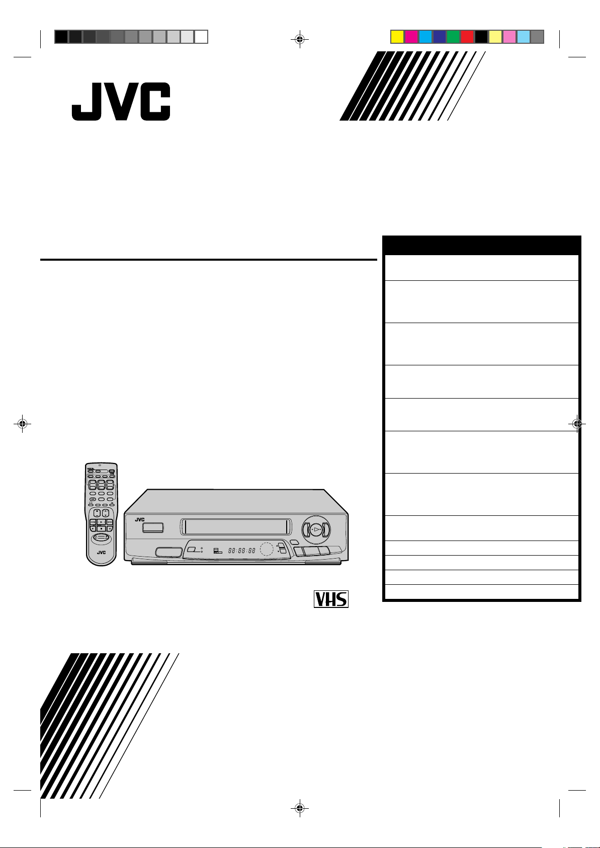
VIDEO CASSETTE RECORDER
HR-J231MS
Press and hold TV button while pressing
OPERATE, TV PROG.+ / –, TV/ VIDEO
DISPLAY
OPERATE
PROG.
TV/VIDEO PICTURE
CLOCK
123
START
STOP DATE
456
DAILY(M-F) WEEKLYADD
789
AUX
TIMER
0
CANCEL
TV
OK
C.RESET
C.MEMORY
TV PROG.
VOL.
PUSH JOG
REMOTE CONTROL UNIT
OPERATE
AUTO SP/LP
TIMER
INTELLIGENT
PICTURE
SP LP
REC
PLAY
NTSC
TIMER
M
PROG
3
2
OK
CH SET
TV
COLOUR
q
8
SYSTEM
5
/
STORE
PAL NTSC
CONTENTS
SAFETY FIRST 2
Safety Precautions ....................................2
INSTALLING YOUR NEW RECORDER 3
Basic Connections ................................... 3
Tune The TV To Your Video Recorder ...... 4
Select Television System .......................... 4
INITIAL SETTINGS 5
On-Screen Displays ................................. 5
Tuner Set ..................................................6
Clock Set .................................................9
PLAYBACK 10
Basic Playback .......................................10
Playback Features .................................. 11
RECORDING 14
Basic Recording .....................................14
Recording Features ................................ 15
TIMER RECORDING 16
Timer Programming ............................... 16
Check And Cancel Programmes ......... 17
Auto SP/LP Timer ............................... 17
EDITING 18
Edit To Or From Another Video
Recorder ................................................18
Edit From A Camcorder ......................... 19
INFORMATION ON MULTI-SYSTEM
COMPATIBILITY 20
TROUBLESHOOTING 22
QUESTIONS AND ANSWERS 24
INDEX 25
SPECIFICATIONS 28
INSTRUCTIONS
PU30425-1840
2 EN
SAFETY FIRST
Safety Precautions
The rating plate and the safety caution are on the rear of the unit.
WARNING: DANGEROUS VOLTAGE INSIDE
WARNING: TO PREVENT FIRE OR SHOCK HAZARD, DO NOT EXPOSE THIS UNIT TO RAIN OR MOISTURE.
CAUTION
n When you are not using the recorder for a long period of
time, it is recommended that you disconnect the power
cord from the mains outlet.
n Dangerous voltage inside. Refer internal servicing to
qualified service personnel. To prevent electric shock or fire
hazard, remove the power cord from the mains outlet prior
to connecting or disconnecting any signal lead or aerial.
n Use the conversion plug depending on the type of your
AC wall outlet.
POWER SYSTEM
This set operates on voltage of AC110 – 240 V` (Rating),
AC90 – 260 V` (Operating), 50/60 Hz with automatic
switching.
IMPORTANT
n Please read the various precautions on this page before
installing or operating the recorder.
n It should be noted that it may be unlawful to re-record
pre-recorded tapes, records, or discs without the consent
of the owner of copyright in the sound or video recording, broadcast or cable programme and in any literary,
dramatic, musical, or artistic work embodied therein.
The OPERATE button does not completely shut off mains
power from the unit, but switches operating current on and off.
Failure to heed the following precautions may result in
damage to the recorder, remote control or video
cassette.
1. DO NOT place the recorder . . .
... in an environment prone to extreme temperatures or
humidity.
... in direct sunlight.
... in a dusty environment.
... in an environment where strong magnetic fields are
generated.
... on a surface that is unstable or subject to vibration.
2. DO NOT block the recorder’s ventilation openings.
3. DO NOT place heavy objects on the recorder or remote
control.
4. DO NOT place anything which might spill on top of the
recorder or remote control.
5. AVOID violent shocks to the recorder during transport.
MOISTURE CONDENSATION
Moisture in the air will condense on the recorder when you
move it from a cold place to a warm place, or under extremely
humid conditions—just as water droplets form in the surface of
a glass filled with cold liquid. Moisture condensation on the
head drum will cause damage to the tape. In conditions where
condensation may occur, keep the recorder turned on for a few
hours to let the moisture dry.
ABOUT HEAD CLEANING
Accumulation of dirt and other particles on the video heads
may cause the playback picture to become blurred or interrupted. Be sure to contact your nearest JVC dealer if such
troubles occur.
ATTENTION
1.This recorder can also receive SECAM colour television
signals for recording and playback.
2.Recordings made of SECAM television signals produce
monochrome pictures if played back on another video
recorder of SECAM standard, or do not produce normal
colour pictures if played back on another video recorder
of PAL standard.
3.SECAM prerecorded cassettes or recordings made with a
SECAM video recorder produce monochrome pictures
when played back with this recorder.
PAL NTSC
n Only cassettes marked "VHS" can be used with this
videorecorder.
n HQ VHS is compatible with existing VHS equipment.
INSTALLING YOUR NEW RECORDER
It's essential that your video recorder be properly connected.
Follow these steps carefully. THESE STEPS MUST BE COMPLETED BEFORE ANY VIDEO OPERATION CAN BE PER-
Basic
FORMED.
EN 3
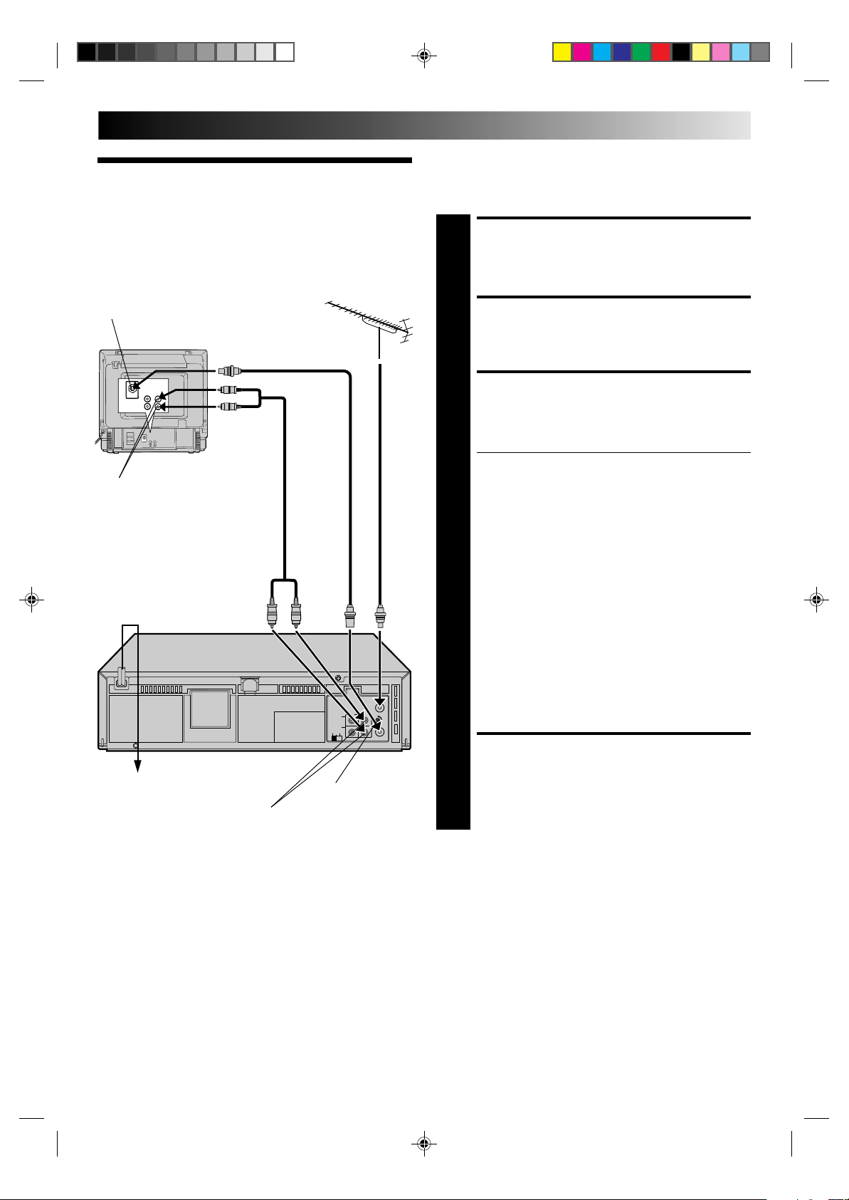
Connections
Aerial terminal
Back of TV
AV-IN terminals
AV Cable
(not provided)
Mains Power
Cord
RF Cable
(provided)
TV
Aerial
Cable
CHECK CONTENTS
Make sure the package contains all of the accessories
listed in “Specifications” (Z pg. 28).
1
SITUATE RECORDER
Place the recorder on a stable, horizontal surface.
2
CONNECT RECORDER TO
TV
The connection method you use depends on the type of
TV you have.
3
RF CONNECTION
●
To Connect To A TV With NO AV Input Terminals . . .
a– Disconnect the TV aerial cable from the TV.
b– Connect the TV aerial cable to the ANT. IN jack
on the rear panel of the recorder.
c– Connect the provided RF cable between the RF
OUT jack on the rear panel of the recorder and the
TV’s aerial terminal.
After step 4, go to "Tune The TV To Your Video
Recorder" on page 4.
AV CONNECTION
●
To Connect To A TV With AV Input Terminals . . .
a– Connect the aerial, recorder and TV as per “RF
CONNECTION”.
b– Connect an optional AV cable between the
AUDIO OUT and VIDEO OUT connectors on the
rear panel of the recorder and the TV’s AV-IN
terminals .
After step 4, go to "Select Television System" on
page 4.
Mains outlet
AUDIO OUT/
VIDEO OUT
Rear View
RF output channel
adjustment screw
CONNECT RECORDER TO
MAINS
Plug the end of the mains power cord into a mains
outlet.
4
4 EN
OPERATE
INSTALLING YOUR NEW RECORDER (cont.)
The video recorder sends picture and sound signals via the RF
connecting cable to your TV on UHF channel 36.
Tune The TV
To Your Video
Recorder
3
2
q
8
5
/
Back of VCR
K
TEST
G
RF
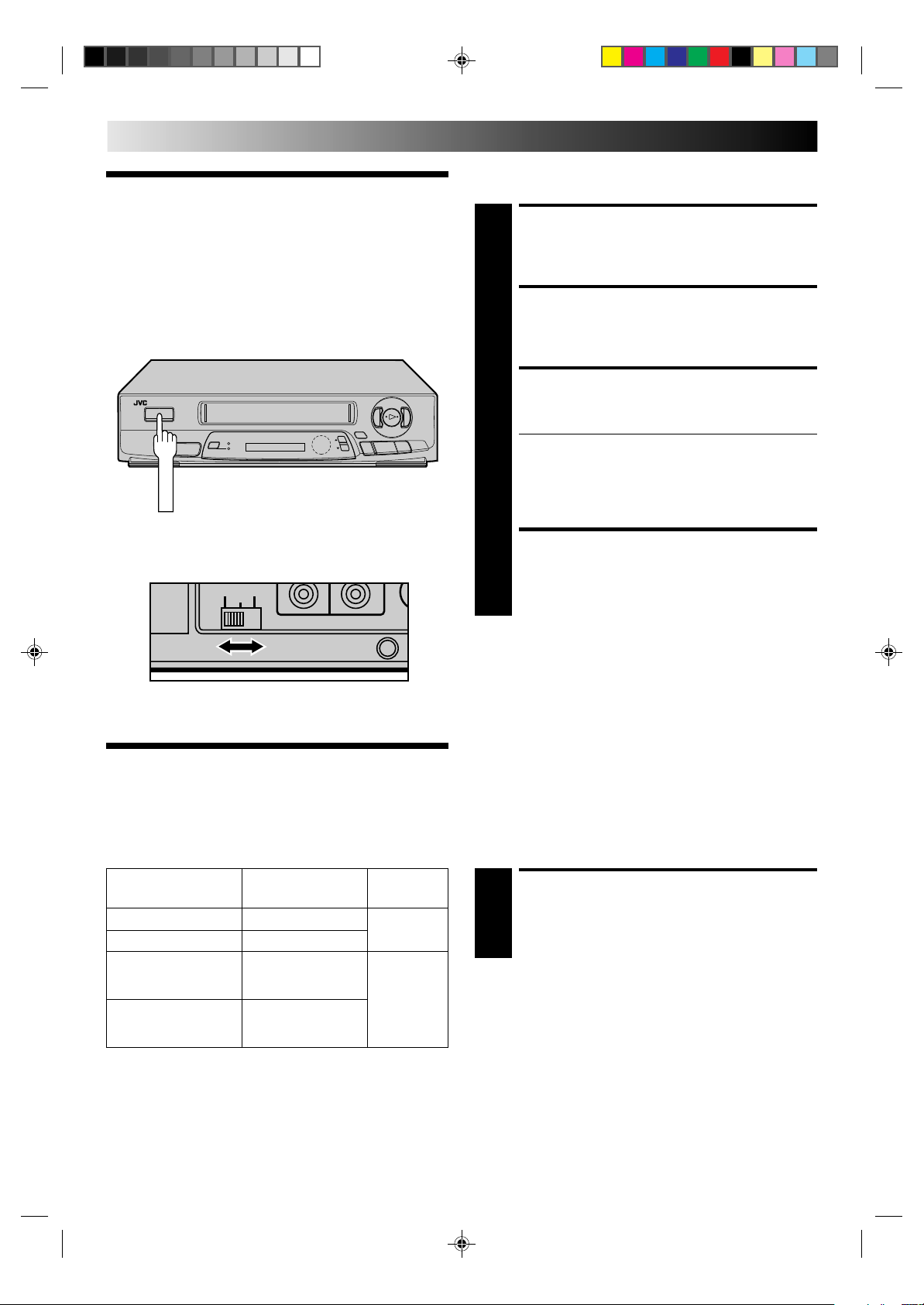
TURN ON THE RECORDER
Press OPERATE.
1
SELECT OUTPUT MODE
Set the TEST/System switch on the back of the recorder
to TEST.
2
SET TV CHANNEL
Set your TV to the video channel (UHF channel 36).
Two white bars appear on screen vertically.
3
● Tune the TV until the bars are as clear as they can be.
● Your TV should be set to the channel designated for
use with a video recorder, or to a spare channel if
there is not a specified video channel on your TV.
● The audio signal may not be heard or may be noisy;
this is not due to any defect of the unit.
RESET OUTPUT MODE
Set the TEST/System switch to the appropriate position
(G or K). Refer to the chart in "Select Television System"
4
below.
NOTES:
●
If CH36 is occupied by a local station, adjust the RF output
channel adjustment screw to use another channel between
CH32 and CH40 instead.
●
If some interference noise is continually seen on the screen,
consult your JVC dealer.
Select Television System
Major countries Colour TV broadcast Switch
China, Mongolia PAL D/K
Russia SECAM D/K
Kuwait, U.A.E,
Indonesia, Singapore, PAL B/G
Thailand, Malaysia
Iran, Saudi Arabia,
Egypt, Morocco, SECAM B/G
Lebanon, Iraq
system position
K
G
SET TEST/SYSTEM SWITCH
Set to the appropriate position depending on your TV
system. (Refer to the chart on the left.)
1
NOTES:
●
If no colours appear on the screen when using a multi-system
television with its system select switch set to AUTO, change
the switch position to correspond to the recorder's RF system
select switch (G or K).
●
For more information on multi-system compatibility.
Z
p.20

INITIAL SETTINGS
OPERATE
OK
On-Screen
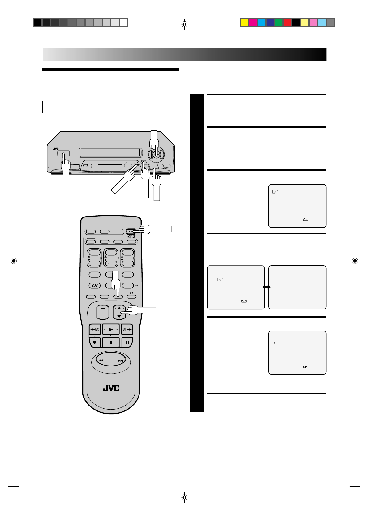
EN 5
You can choose whether or not to have various operational
indicators appear on screen, by setting this function ON or OFF.
Messages appear in the language you select.
Use the buttons on the remote control for this procedure.
Displays
Turn on the TV and select the VIDEO channel (or AV mode).
2
q
8
5
/
OPERATE
123
456
789
0
OSD ( )
TURN ON THE RECORDER
Press OPERATE.
1
SELECT LANGUAGE
Press OSD( ). The Language screen appears. Place the
pointer next to the language of your choice by pressing
2
TV PROG.5/∞, then press OK to enter your selection.
3
The O.S.D. (On-Screen Display) Set screen appears.
ENGLISH
[TV PROG
[OSD] : EXIT
5
] =
∞
O.S.D. : ON
:ON/OFF
[OSD] :EXIT
ENABLE/DISABLE
ON-SCREEN DISPLAY
The default setting is “ON”, so if you want on-screen
displays, leave the setting as is and go to step 4. If you
3
don’t want the displays to appear, press OK to set
“O.S.D.” to “OFF”.
CLOSE MODE SELECT
SCREEN
Press OSD ( ).
4
TV PROG.5∞
The superimposed indication on the TV screen tells you what the recorder is doing.
1– Operation mode indicators
2– Channel position number/Aux. indicator (AUX)
3– Cassette loaded mark
4– Tape speed SP/LP/EP
5– Colour System indicator (Z pg. 20)
6– Clock display
7– Current day/month/year
8– Tape direction
9– Tape position indicator (Z pg. 13)
10– Counter display (including Counter Memory indicator)
2
6
7
9
1
PR. 12 ] SP
23 : 59 PAL
31. 12. 96
++
0
M –9 : 59 : 59
q6
+
+
4
5
3
8
10
6 EN
TV PROG.
OK
STORE
CH SET
OPERATE
OK
Tuner Set
INITIAL SETTINGS (cont.)
Your recorder needs to memorise all necessary stations in
channel positions in order to record TV programmes. Once
stored, you can call them up with the TV PROG. buttons
without going through any vacant channels.
Turn on the TV and select the VIDEO channel (or AV mode).
3
2
q
8
5
/
OPERATE
123
456
789
0
TV PROG.
TURN ON THE RECORDER
Press OPERATE.
1
ACCESS CHANNEL SET
MODE SELECT SCREEN
Press and hold CH SET for more than 2 seconds. The
Channel Set Mode Select screen appears.
2
SELECT MODE
Press TV PROG.5/∞ to
place the pointer next to
3
"SEARCH/STORE", then
press OK. The Band Select
screen appears.
[TV PROG
[CANCEL] :EXIT
SELECT BAND
Press TV PROG.5/∞ to place the pointer next to the
band of your choice, then press OK to initiate Auto
4
Channel Search.
BAND SELECT
VHF L
VHF H
UHF
5
[TV PROG
[CH SET] :EXIT
] =
∞
AUTO SEARCH PROCEEDING
PLEASE WAIT
VHF L 00
[CH SET] :EXIT
SEARCH/STORE
DELETE
FINE TUNING
5
] =
∞
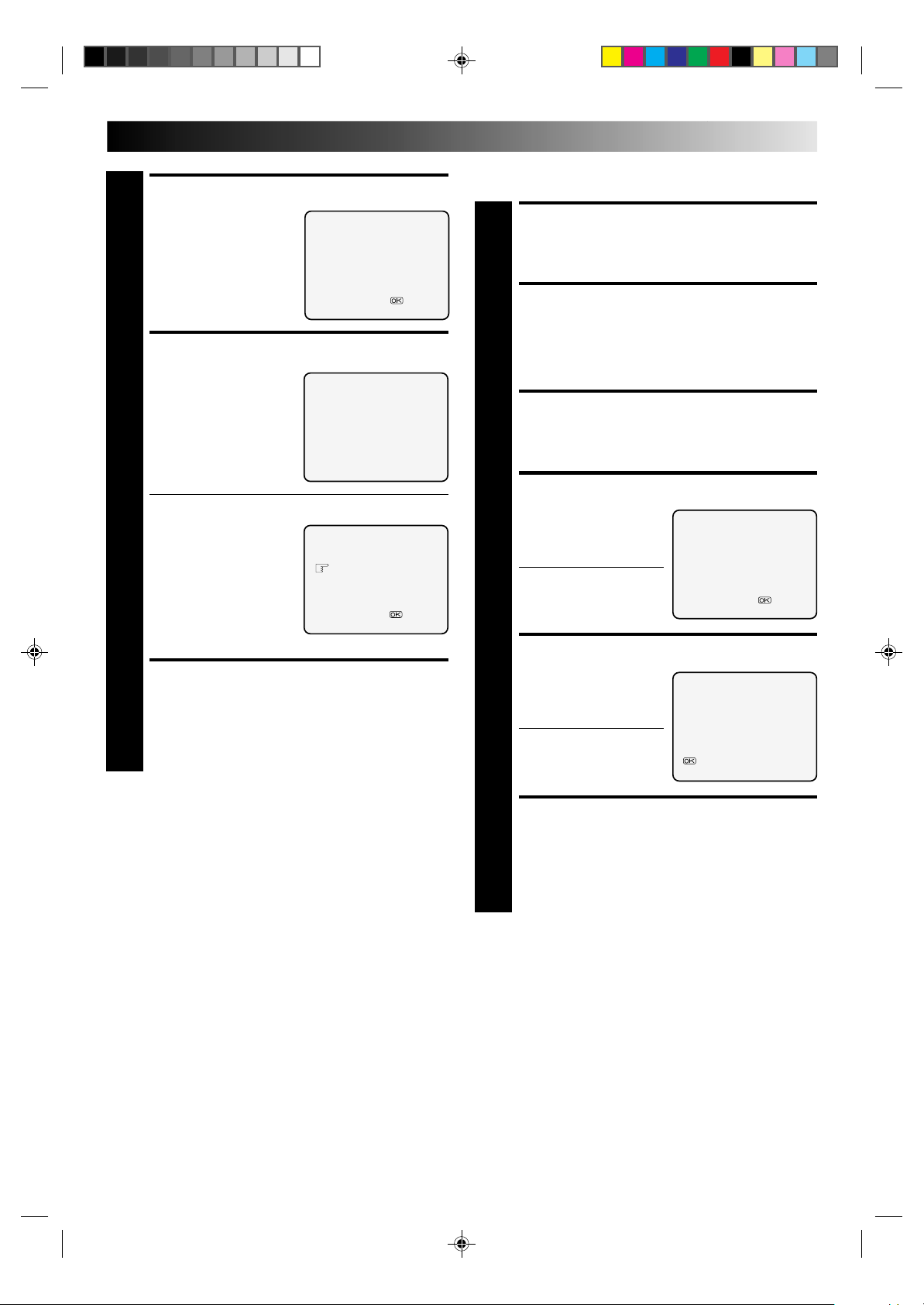
SET DESIRED CHANNEL
The following screen
appears when a station is
5
detected. To store the
detected station, place the
pointer next to "STORE" by
pressing TV PROG.5/∞,
then press OK.
If you don't want to store
the station, press TV
PROG.5/∞ to place the pointer next to "CONTINUE",
then press OK. Auto Channel Search will start resume.
● The blueback screen and the TV picture currently
being broadcast appear alternately for 8 seconds
each.
STORE
CONTINUE
[TV PROG
[CH SET] :EXIT
5
] =
∞
EN 7
SELECT POSITION
Press TV PROG.5/∞ until
an open position in which
6
you want to store a
channel appears, then
press OK.
SELECT NUMBER
TV PROG. 1
[TV PROG
[CH SET] :EXIT
STORE CHANNEL
If fine tuning is not
necessary, simply press
7
STORE. For fine tuning
adjustment, press TV
PROG.5/∞ until the
picture becomes clearer,
then press STORE.
● To continue Auto Channel Search, press TV PROG.5/∞
to select "CONTINUE",
then press OK. Repeat
steps 5 – 7 as necessary.
● To set channels for other
bands, press TV
PROG.5/∞ to select
"BAND SELECT", then
press OK to go back to
the Band Select screen.
Repeat steps 4 – 7.
TV PROG. 1
[STORE] :STORE
[TV PROG5] :FINE TUNING +
[TV PROG∞] :FINE TUNING –
[CH SET] :EXIT
TV PROG. 1 ADDED
CONTINUE
BAND SELECT
[TV PROG
[CH SET] :EXIT
RETURN TO NORMAL
SCREEN
Press CH SET.
8
Delete A Stored Channel
TURN ON THE RECORDER
Press OPERATE.
1
5
] =
∞
ACCESS CHANNEL SET
MODE SELECT SCREEN
Press and hold CH SET for more than 2 seconds. The
Channel Set Mode Select screen appears.
2
SELECT MODE
Press TV PROG.5/∞ to place the pointer next to
"DELETE", then press OK.
3
SELECT CHANNEL
Press TV PROG.5/∞ until
the position number of the
4
channel you wish to delete
appears.
● If the on-screen display
is hard to read, refer to
5
] =
∞
the recorder's display
panel.
DELETE CHANNEL
Press OK twice.
The screen shows the
5
selected channel has been
deleted.
● To delete another
channel, press OK again,
then repeat steps 4 – 5.
SELECT NUMBER
TV PROG. 1
5
[TV PROG
[CH SET] :EXIT
[CH SET] :EXIT
] =
∞
TV PROG. 1 DELETED
:CONTINUE
RETURN TO NORMAL
SCREEN
Press CH SET.
6
NOTE:
If you skipped a channel by mistake, perform steps 1 – 8 on
pages 6 and 7 to re-store it.
8 EN
TV PROG.
OK
STORE
CH SET
OPERATE
OK
2
q
8
5
/
OPERATE
3
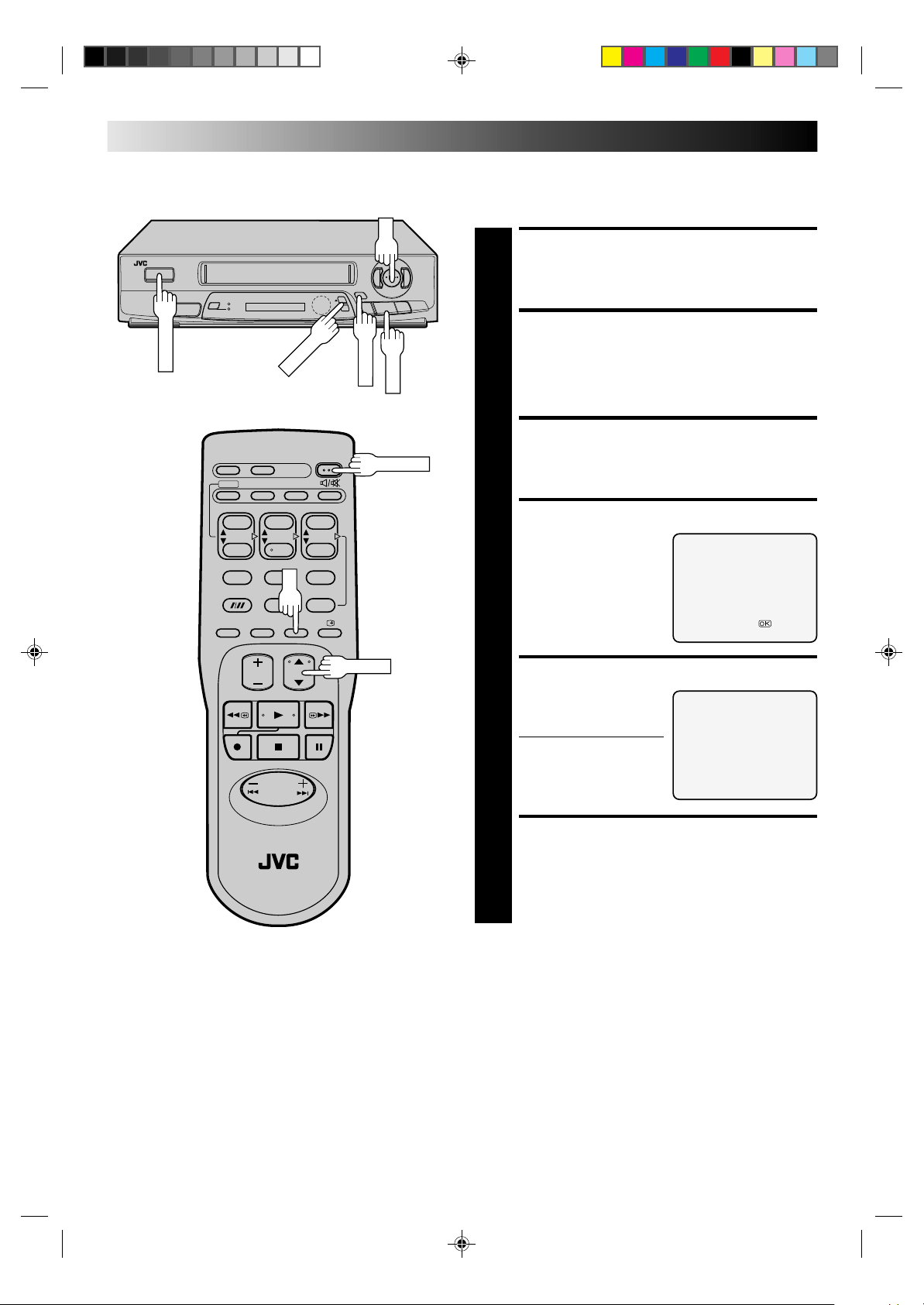
INITIAL SETTINGS (cont.)
Fine-Tuning Channels
Already Stored
TURN ON THE RECORDER
Press OPERATE.
1
ACCESS CHANNEL SET
MODE SELECT SCREEN
Press and hold CH SET for more than 2 seconds. The
Channel Set Mode Select screen appears.
2
SELECT MODE
Press TV PROG.5/∞ to place the pointer next to "FINE
TUNING", then press OK.
3
123
456
789
0
TV PROG.
SELECT CHANNEL
Press TV PROG.5/∞ so
that the position number of
4
the channel you want to
fine-tune appears, then
press OK.
PERFORM TUNING
Press TV PROG.5/∞ until
the picture becomes
5
clearer, then press STORE.
● To fine-tune another
channel, press OK and
repeat steps 4 – 5.
RETURN TO NORMAL
SCREEN
Press CH SET.
6
SELECT NUMBER
TV PROG. 1
5
[TV PROG
[CH SET] :EXIT
[STORE] :STORE
[TV PROG5] :FINE TUNING +
[TV PROG∞] :FINE TUNING –
[CH SET] :EXIT
] =
∞
TV PROG. 1
OPERATE
OK
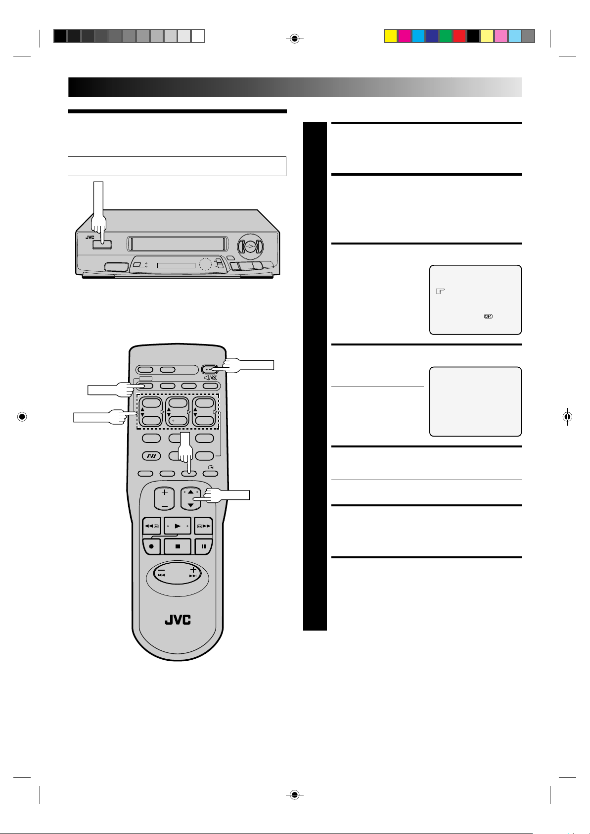
Use the buttons on the remote control for this procedure.
EN 9
Clock Set
Turn on the TV and select the VIDEO channel (or AV mode).
2
q
8
5
/
OPERATE
CLOCK
123
NUMBER5∞
456
789
TURN ON THE RECORDER
Press OPERATE.
1
ACCESS MODE SELECT
SCREEN
Press CLOCK.
2
3
SELECT MODE
Press TV PROG.5/∞ to
place the pointer next to
3
"CLOCK SET", then press
OK. The Clock Set screen
appears.
SET TIME
Use NUMBER key "1(5)"
or "4(∞)" to set the time.
4
● Press and hold either
button to delay or
advance the time by 30
minutes.
TIMER PROGRAMMING
CLOCK SET
5
[TV PROG
[CANCEL] :EXIT
TIME DATE YEAR
0:00 01:01 00
[1 – 6]
[PROG./CLOCK] :EXIT
] =
∞
CLOCK SET
0
TV PROG.
NOTE:
If, in step 7, the year digits are automatically cleared, it is
possible that you have input 29th February for a non-leap year.
Input the correct data.
SET DATE
Use NUMBER key "2(5)" or "5(∞)" to set the date.
● Press and hold either button to change the date by 15
5
days.
SET YEAR
Use NUMBER key "3(5)" or "6(∞)" to set the year.
6
RETURN TO NORMAL
SCREEN
Press CLOCK.
7
To Make Corrections
Perform steps 1 – 3 to call up the Clock Set screen, use
NUMBER keys "1" – "6" to make the correction, then press
CLOCK.
 Loading...