

Page 1
Version 1.12
GY-HD250U Studio Systems Reference Manual
Page 2
Table of contents
Page
Section I - Short Length Multi Core Studio Configurations 4
SD Studio System: 4
SD System with RM-P210U 4
SD Studio System Components Price List 5
SD Studio Key features and users benefits 6
Additional Information 7
HD Studio System: 8
HD System Diagram with RM-HP250AU SYSTEM 1 (HD SDI) 8
HD System Diagram with RM-HP250AU SYSTEM 2 (HD analog component) 9
HD System Diagram with RM-P210U 10
HD Studio System Components Price List 11
HD Studio Key features and user benefits 12
Additional Information 13
Section II - Medium Length Fiber Cable Studio Configurations 14
CAMPLEX: 14
Shoulder CP-301C/CP-701C studio system diagram 15
Shoulder Studio Components Price List (Fiber) 16
Tripod mounted CP-301C/CP-701C studio system diagram w/o Sled 17
Tripod Mounted Studio Components Price List (Fiber) 18
Sled mounted CP-301C/CP-701C studio system diagram 19
Sled Mounted Studio with Sled Components Price List (Fiber) 20
CAMPLEX System Key features and Customer Benefit 21
Additional Information and Limitations 22
Version 1.12
Section III - Long Length Fiber Cable connected Studio Configurations 23
Telecast Fiber: 23
Key Features and Customer Benefit 23
Shoulder/w power studio system diagram 24
Shoulder Studio with Power Components Price List (Fiber) 25
Tripod mounted/w power studio system diagram 26
Tripod Mounted Studio with Power Components Price List (Fiber) 27
1
Page 3

Table of contents
Page
Sled Mounted/w Power studio system diagram 28
Sled Mounted Studio with Power Studio Components List (Fiber) 29
Telecast System Key Features and User Benefit 30
Additional Information 31
Telecast Fiber CCU locally Power 32
Shoulder battery powered studio system diagram 33
Shoulder Battery Powered Studio Components Price List (fiber) 34
Tripod Mounted w/o Sled battery powered studio system diagram 35
Tripod Mounted Battery Powered Studio Components Price List (Fiber) 36
Sled Mounted with battery or off board of on board AC power studio system
diagram 37
Sled Mounted Battery Powered Studio Components Price List (Fiber) 38
Section IV - POV System configuration 39
POV Pan/Tilt System: 39
POV Pan/Tilt system diagram 39
POV System Components Price List 40
Key features and user benefits 40
RCU control of cameras up to 2000 feet with ESI Model 55 System: 41
RCU control of cameras up to 2000 feet system diagram 41
RCU control of cameras up to 2000 feet with ESI Model 55 System Components
Price List 42
Key features and user benefits 42
Version 1.12
Section V - Supplementary Information 43
“VF SIGNAL” Menu 43
How to use Sony 26Pin Cable with KA-HD250U 44
How to use Sony 26Pin cable with RM-P210U 45
GY-HD250U/KA-HD250U and JVC CCUs Power connectivity table 45
HD-SDI Cable Lengths 46
Telecast Fiber Rattler – Fiber Tx/Rx 46
2
Page 4

Table of contents
Page
Section VI - Accessories 47
KA-R25U: Return Video Box 47
KA-BP250: Intermediate Plate (handled by JPC) 48
HD 1/3”mount bayonet lenses: 49
KA-V400U: 6pin/20pin Viewfinder Adapter 50
RM-LP25U: Local Remote Control Panel 51
RM-HP250AU: HD/SD 26Pin CCU 52
RM-HP250AU Interconnect Diagram 53
Interfacing RM-HP250AU with common Intercom system: 54
Connection to an unbalanced audio Intercom system 55
Connection to a balanced audio Intercom system 56
VF-HP840U: Color Studio View Finder 57
VF-HP840U and KA-HD250U Interconnect Diagram 58
VC-P840U: 20Pin Viewfinder Cable 59
Power applied to GY-HD250U/GY-HD200UB via Battery Mount 60
Power applied to GY-HD250U/GY-HD200UB via 4 pin XLR 61
KA-HD300U: Portable HD Studio Adapter 62
KM-H3000U/KM-H2500U: Multi Format HD-SDI Production Switcher 63
Studio System Components Weight and Power Dissipation List for Tripod Mounted 64
Version 1.12
3
Page 5
Section I - Short Length Multi Core Studio Configurations
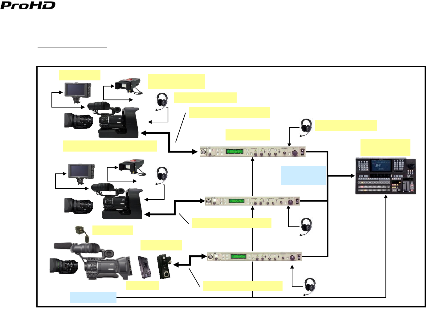
SD Studio System:
Typical Application: SD -production studio, Schools etc
SD System with RM-P210U
Version 1.12
VF-HP840U
KA-HD250U* / KA-HD250U(A)**
KA-R25U***
VF-P400U
w/KA-V400U
DT-109 or RH-1R5
VC-PxxxU Control cable
DT-109 or RH-1R5
RM-P210U
Live video
Switcher
SD Analog
Component
VC-PxxxU Control cable
KA-HD300E
JVC-PV***
House Sync
* Use KA-HD250U / KA-HD250U(A) with VF-P400U.
** Use KA-HD250U(A) with VF-HP840U.
*** Supplied with KA-HD300E
VC-PxxxU Control cable
4
Page 6
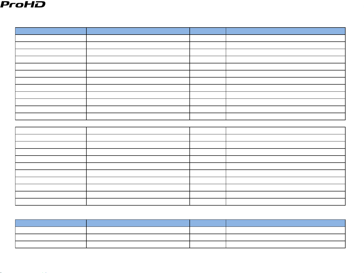
SD Studio System Components Price List
Model Description Price Note
GY-HD250CHU Pro HD Camcorder $9,995.00 without 16X lens
GY-HD250U Pro HD Camcorder $10,995.00 With 16X Lens
KA-HD250U(A) Studio Adapter $3,000.00 For Tripod mount
KA-HD300E Studio Adapter (for shoulder mount) TBD with KA-R25U and JVC-PV
VF-HP840U 8.4" HD/SD Studio Viewfinder $3,200.00
VF-P400U 4" Viewfinder $875.00
KA-V400U Viewfinder Cable $225.00 20-pin/6-pin Adapter
RM-P210U SD Camera Control Unit $1,995.00
VC-P110U Multi core Camera Cable 5M $480.00 5m
VC-P112U Multi core Camera Cable 20M $1,050.00 20m
VC-P113U Multi core Camera Cable 50M $1,850.00 50m
VC-P114U Multi core Camera Cable 100M $3,250.00 100m
Optional Components
Th13X3.5BRMU Fujinon Wide Angle $7,650.00
Th17X5BRM Fujinon Wide Angle $3,300.00
HTs18x4.2BRM Fujinon 18x High Quality Lens $10,800.00
KT20x5BKRS Canon 20x High Quality Lens $9,800.00
HZ-FM13U Manual Focus Control $685.00 Fujinon 17X, 13X
HZ-FM15U Manual Focus Control $685.00 Canon 20X
HZ-FM500 Manual Focus Control $820.00 Fujinon 16X
HZ-ZS13U Zoom Servo Control $750.00 Fujinon 13X, 16X, 17X, Canon 20X
ACM-12 1/2" to 1/3" Mount Converter $799.00
ACM-17 1/2" to 2/3" Mount Converter $799.00
MS-11 Zoom & Focus kit Fuji 18X lens $2,880.00 Fujinon 18X
Third Party Components
Model Description Price Note
DT-109 Headset $209.95 BeyerDynamic
K109.38 1.5m DT-109 Connecting cable $49.50 BeyerDynamic
PH-1R5 Headset $175.50 Telex
Version 1.12
5
Page 7
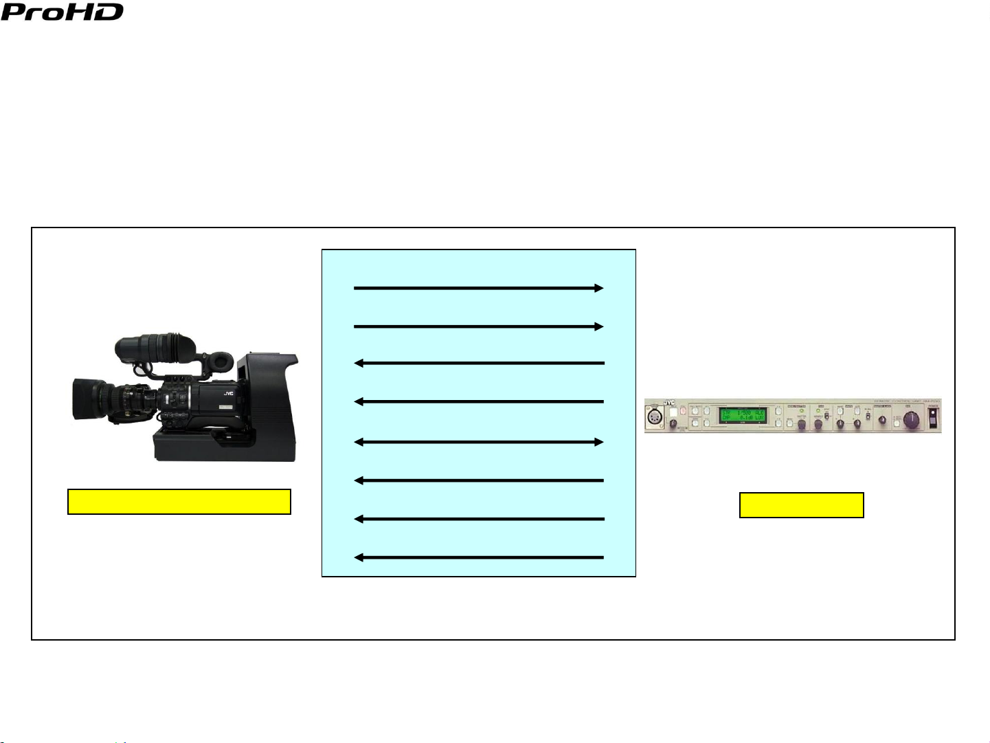
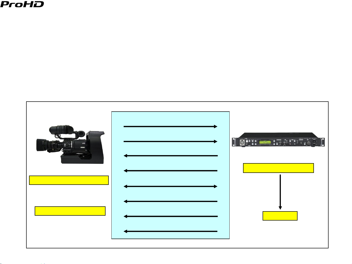
SD Composite
SD Component
Genlock, VBS
Power
Call/Tally
Control
Return Video
Intercom
SD Studio Key features and users benefits
The GY-HD250U w/KA-HD250U/U(A) can be used to construct an economical SD studio system that produces
stunning 16:9 or 4:3 SD images.
Investment is future proofed. Upgrading from an SD to an HD system will require changing the video interface only.
When replacing a GY-DV550U, the original CCU the RM-P210U; the 26pin control cable and the studio viewfinder VF-
P400U can continue to be used.
When needed, the GY-HD250U can be used as an ENG camera by detaching it from the KA-HD250U/U(A).
Version 1.12
GY-HD250U + KA-HD250U/U(A)
RM-P210U
Fig. 1 Signal Flow between CCU and Camera
6
Page 8

Additional Information
GY-HD250U’s “VF SIGNAL” menu should be set to “RGB” when VF-P400U is used. All VF displays are available
except focus assist.
When using VF-HP840U in a SD studio, Set the GY-HD250U’s “VF SIGNAL” menu to “RGB”.
SD CMP available only; RM-P210U can not pass full bandwidth HD Y, R-Y, B-Y.
Genlock must be NTSC VBS only – HD Tri level sync can not be passed by RM-P210U back to the GY-HD250U.
GY-HD250U’s “ANALOG OUT CHAR.” menu should be set to “OFF”, – otherwise they will appear at RM-P210U
component outputs.
GY-HD250U’s “TALLY SYSTEM” menu should be set to “STUDIO”.
Sony 26pin Cable can be used to connect RM-P210U with the KA-HD250U/U(A).
Version 1.12
7
Page 9
HD Studio System:
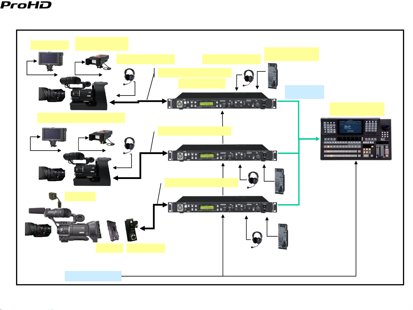
HD System Diagram with RM-HP250AU SYSTEM 1 (HD SDI)
Version 1.12
VF-HP840U
KA-HD250U* / KA-HD250U(A)**
KA-R25U
VF-P400U
w/KA-V400U
DT-109 or RH-1R5
HD-SDI *
DT-109 or RH-1R5
VC-PxxxU Control cable
RM-HP250AU
VC-PxxxU Control cable
RM-LP25U
(RM-LP55U/LP57U)
HD-SDI*
KM-H2500U/H3000U
or
VC-PxxxU Control cable
JVC-PV KA-HD300U
House sync
* Either the HD-SDI outputs of the RM-HP250AU derived from the HD component signal or the HD-SDI output of the GY-HD250U can be applied to
the HD-SDI switcher inputs.
** When using VF-HP840U as viewfinder, camera adapter must be KA-HD250U(A).
8
Page 10
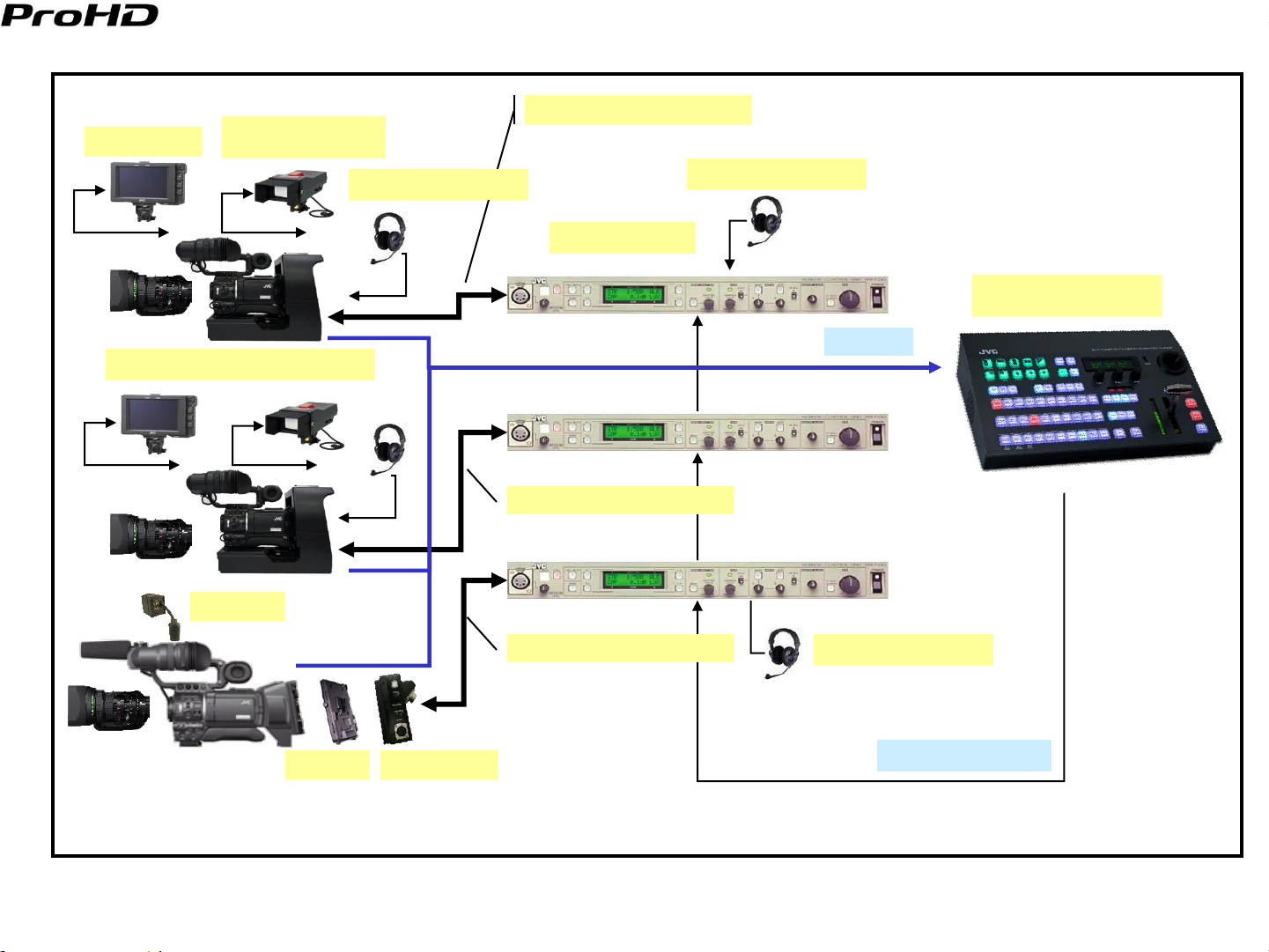
HD System Diagram with RM-HP250AU SYSTEM 2 (HD analog component)
Version 1.12
VF-HP840U
KA-HD250U* / KA-HD250U(A)**
KA-R25U
VF-P400U
w/KA-V400U
DT-109 or RH-1R5
VC-PxxxU Control cable
VC-PxxxU Control cable
DT-109 or RH-1R5
RM-HP250AU
VC-PxxxU Control cable
RM-LP25U
(RM-LP55U/LP57U)
HD Analog
Component*
HD Analog Switcher
JVC-PV KA-HD300U
House sync
* The component HD signal output of the RM-HP250AU can be applied to a HD component analog switcher.
** When using VF-HP840U as viewfinder, camera adapter must be KA-HD250U(A).
9
Page 11
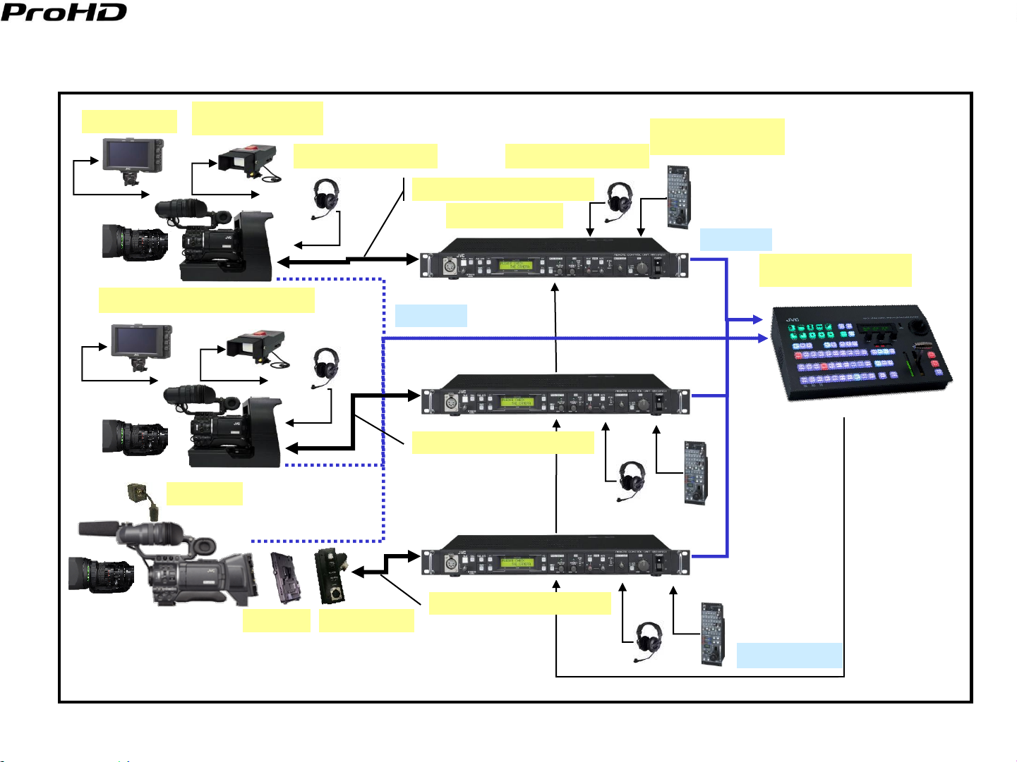
HD System Diagram with RM-P210U
Version 1.12
VF-HP840U
KA-HD250U* / KA-HD250U(A)**
KA-R25U
VF-P400U
w/KA-V400U
DT-109 or RH-1R5
VC-PxxxU Control cable
DT-109 or RH-1R5
RM-P210U
KM-H2500U/H3000U
HD-SDI
VC-PxxxU Control cable
VC-PxxxU Control cable
JVC-PV KA-HD300U
** When using VF-HP840U as viewfinder, camera adapter must be KA-HD250U(A).
DT-109 or RH-1R5
House sync
10
Page 12
HD Studio System Components Price List
Model
Description Price Note
GY-HD250CHU Pro HD Camcorder $9,995.00 without 16X lens
GY-HD250U Pro HD Camcorder $10,995.00 With 16X Lens
KA-HD250U(A) Studio Adapter $3,000.00 For Tripod mount
KA-HD300E Studio Adapter (for shoulder mount) TBD with KA-R25U and JVC-PV
VF-P400U 4" Viewfinder $875.00
KA-V400U Viewfinder Cable $225.00 20-pin/6-pin Adapter
VF-HP840U 8.4" HD/SD Studio Viewfinder $3,200.00
RM-P210U SD Camera Control Unit $1,995.00
RM-HP250AU HD Camera Control Unit $3,495.00
RM-LP25U Local Remote Control Panel $3,995.00
RM-LP55U Local Remote Control Unit $815.00
RM-LP57U Local Remote Control Panel $910.00
KM-H2500U HD-SDI Switcher $14,500.00 6 SDI MultiDefinition Input
KM-H3000U HD-SDI Switcher $17,500.00 12 SDI MultiDefinition Input
VC-P110U Multi core Camera Cable 5M $480.00 5m
VC-P112U Multi core Camera Cable 20M $1,050.00 20m
VC-P113U Multi core Camera Cable 50M $1,850.00 50m
VC-P114U Multi core Camera Cable 100M $3,250.00 100m
Options
Th13X3.5BRMU Fujinon Wide Angle $7,650.00
Th17X5BRM Fujinon Wide Angle $3,300.00
HTs18x4.2BRM Fujinon 18x High Quality Lens $10,800.00
KT20x5BKRS Canon 20x High Quality Lens $9,800.00
HZ-FM15U Manual Focus Control $685.00 Canon 20X
HZ-FM13U Manual Focus Control $685.00 Fujinon 17X, 13X
HZ-FM500 Manual Focus Control $820.00 Fujinon 16X
HZ-ZS13U Zoom Servo Control $750.00 Fujinon 13X, 16X, 17X, Canon 20X
ACM-12 1/2" to 1/3" Mount Converter $799.00
ACM-17 1/2" to 2/3" Mount Converter $799.00
MS-11 Zoom & Focus kit Fuji 18X lens $2,880.00 Fujinon 18X
Third Party Components
Model
Description Price Note
DT-109 Headset $209.95 BeyerDynamic
K109.38 1.5m DT-109 Connecting cable $49.50 BeyerDynamic
PH-1R5 Headset $175.50 Telex
RG-59 or RG6 or RG 11 HD-SDI Cable Belden, Canare
Version 1.12
11
Page 13
Version 1.12
SD Composite
SD Component/HD Component
Genlock, VBS/Tri-level sync
Power
Call/Tally
Control
Return Video
Intercom
HD Studio Key features and user benefits
The GY-HD250U w/KA-HD250U/U(A) can be used to build an economical HD studio system that produces stunning
images.
Both HD component and HD-SDI video is supported giving user flexibility of using a component switcher or a HD-SDI
switcher.
The new RM-HP250AU gives the user the flexibility of connecting an additional local remote control to the studio system.
A live 720P or 1080i signal can be outputted depending on the user’s switcher requirements.
When replacing a GY-DV550U based studio system, the original 26pin control cable and studio viewfinder VF-P400U can
continue to be used, or replaced with the new VF-HP840U HD/SD viewfinder.
Existing user’s 26Pin Sony Cable can be used to connect RM-HP250AU and KA-HD250U/U(A).
When needed, the GY-HD250U can be readily detached from the KA-HD250U/U(A)(Sled) and used as an ENG camera.
GY-HD250U w/KA-HD250U/U(A)
RED- with RM-HP250AU
RM-HP250AU/RM-P210U
Fig 2 HD System Signal Flow between CCU and Studio Camera
HD-SDI
12
Page 14

Additional Information
When using a VF-HP840U and a component or digital switcher:
GY-HD250U’s “ANALOG OUT CHAR.” menu should be set to “OFF”.
Set the “VF SIGNAL” menu to “COMPONENT”.
If a VF-P400U is used as the view finder, set the GY-HD250U’s “VF SIGNAL” menu to “RGB”.
Do not turn “SDI OUT CHAR.” menu setting to “ON”.
GY-HD250U’s “TALLY SYSTEM” menu should be set to “STUDIO”.
Version 1.12
13
Page 15
Version 1.12
Section II - Medium Length Fiber Cable Studio Configurations
Typical Applications:
Medium length Fiber Cable Studio Configurations are used for EFP, Sports and Events requiring the CCU to be located
more than 100m from the Camera’s location. When multi-core cable lengths exceed 100m, the multi-Core cable weight
becomes excessive. For lengths greater than 100m a fiber cable can be used for applications that do not need power to be
delivered to the camera or a hybrid (combined fiber and copper cable) that also delivers power is used to connect the Studio
Camera to the base station. Camplex and Telecast Fiber are two companies that produce systems that use either fiber or
hybrid cables to connect the camera to the CCU.
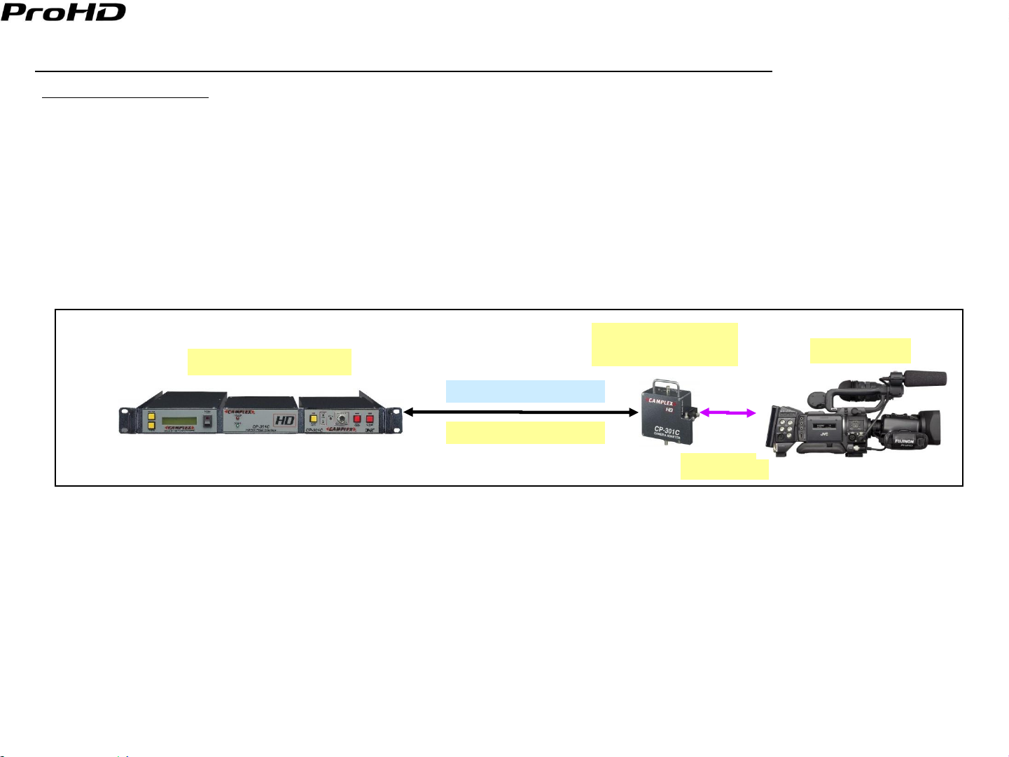
CAMPLEX:
CAMPLEX produces economical hybrid cable connected systems that integrate with the GY-HD250U. Their system
consists of a Camera Adapter mounted on the Camera, a Hybrid Fiber Cable and a Base Station.
CP-301C/CP-701C
Base Station (CCU)
Camera Adapter
Power and Signals
GY-HD250U
Hybrid Cable
Cabling
Camplex System Diagram
The Camera Adapter with additional cabling provides a signal interface between the camera and the Hybrid Cable.
The Hybrid cable consists of a coaxial cable whose center conductor gauge depends on the customer’s power
requirements and a fiber cable. Both are enclosed in a single sheath.
The Fiber cable carries the HD-SDI optical signal back to the base station where it is converted back to an electrical
signal HD-SDI signal.
The center conductor in the coax carries both power and all the required signals between the Base station and the
Camera adapter.
14
Page 16
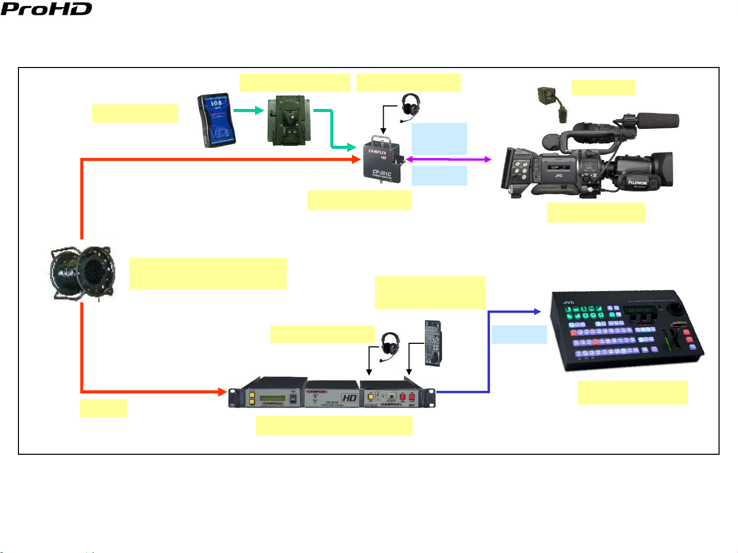
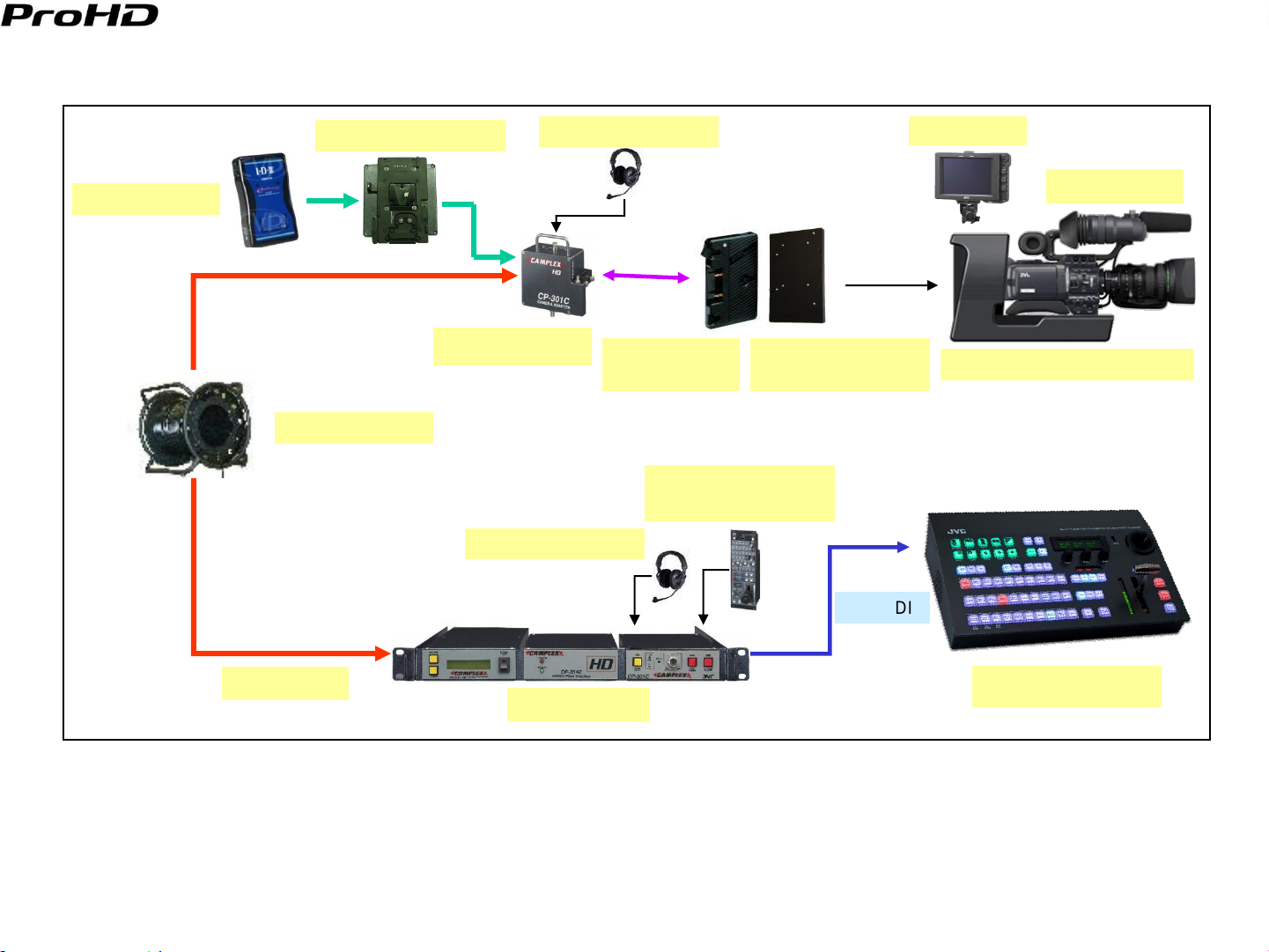
Shoulder CP-301C/CP-701C studio system diagram
Version 1.12
Battery Powered
Hybrid Cable- BNC and ST
Fiber connectors
BKW - V mount Plate
CP-301C/CP-701C
DT-109 or RH-1R5
DT-109 or RH-1R5
Signal
Cabling
Power
RM-LP25U
(RM-LP55U/LP57U)
KA-R25U
GY-HD250U
HD-SDI
900m
KM-H2500U/H3000U
Base Station CP301C/CP701C
15
Page 17
Model Description Price Note
GY-HD250CHU Pro HD Camcorder $9,995.00 without 16X lens
GY-HD250U Pro HD Camcorder $10,995.00 With 16X Lens
RM-LP25U Local Remote Control Panel $3,995.00
RM-LP55U Local Remote Control Unit $815.00
RM-LP57U Local Remote Control Panel $910.00
KM-H2500U HD-SDI Switcher $14,500.00 6 SDI MultiDefinition Input
KM-H3000U HD-SDI Switcher $17,500.00 12 SDI MultiDefinition Input
KA-R25U Return Video Box $599.00
Options
Th13X3.5BRMU Fujinon Wide Angle $7,650.00
Th17X5BRM Fujinon Wide Angle $3,300.00
HTs18x4.2BRM Fujinon 18x High Quality Lens $10,800.00
KT20x5BKRS Canon 20x High Quality Lens $9,800.00
HZ-FM15U Manual Focus Control $685.00 Canon 20X
HZ-FM13U Manual Focus Control $685.00 Fujinon 17X, 13X
HZ-FM500 Manual Focus Control $820.00 Fujinon 16X
HZ-ZS13U Zoom Servo Control $750.00 Fujinon 13X, 16X, 17X, Canon 20X
MS-11 Zoom & Focus kit Fuji 18X lens $2,880.00 Fujinon 18X
ACM-12 1/2" to 1/3" Mount Converter $799.00
ACM-17 1/2" to 2/3" Mount Converter $799.00
Model Description Price Note
CP701 Camera Adapter + Base station + Pwr $13,335.00 This price includes all necessary options
CP301C S5 Camera Adapter + Base stationm + Pwr $10,134.00 This price includes all necessary options
CP301C S2 Camera Adapter + Base Station + Battery Mount $8,984.00 For Battery powered applications
Hybrid cable 2 Fibers + Coax $1.50 Camplex
Power Surge Absorber $625.00 Absorbs additional current draw used
Reel $500.00 Camplex
Interface Cabling $425.00 Camplex Fiber $400 to $450
DT-109 Headset $209.95 BeyerDynamic
K109.38 1.5m DT-109 Connecting cable $49.50 BeyerDynamic
PH-1R5 Headset $175.50 Telex
Third Party Components
Shoulder Studio Components Price List (Fiber)
Version 1.12
16
Page 18
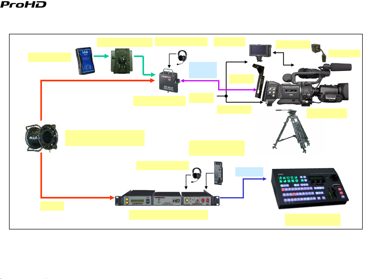
Tripod mounted CP-301C/CP-701C studio system diagram w/o Sled
Version 1.12
Battery Powered
BKW - V mount Plate
Hybrid Cable- BNC and ST
Fiber connectors
DT-109 or RH-1R5
CP-301C/CP-701C
DT-109 or RH-1R5
VF-HP840U
Signal
Cabling
SA-K840
Power
VC-Y250US
RM-LP25U
(RM-LP55U/LP57U)
VC-P840U
KA-R25U
GY-HD250U
HD-SDI
900m
Base Station CP301C/CP701C
KM-H2500U/H3000U
17
Page 19
Model Description Price Note
GY-HD250CHU Pro HD Camcorder $9,995.00 without 16X lens
GY-HD250U Pro HD Camcorder $10,995.00 With 16X Lens
RM-LP25U Local Remote Control Panel $3,995.00
RM-LP55U Local Remote Control Unit $815.00
RM-LP57U Local Remote Control Panel $910.00
KM-H2500U HD-SDI Switcher $14,500.00 6 SDI MultiDefinition Input
KM-H3000U HD-SDI Switcher $17,500.00 12 SDI MultiDefinition Input
KA-R25U Return Video Box $599.00
VF-HP840U 8.4" HD/SD Studio Viewfinder $3,200.00
SA-K840 Viewfinder Bracket $300.00 For VF-HP840U without KA-HD250U
VC-P840U Viewfinder Cable $315.00 For VF-HP840U without KA-HD250U
VC-Y250US Y XLR Power Cable $75.00
Options
Th13X3.5BRMU Fujinon Wide Angle $7,650.00
Th17X5BRM Fujinon Wide Angle $3,300.00
HTs18x4.2BRM Fujinon 18x High Quality Lens $10,800.00
KT20x5BKRS Canon 20x High Quality Lens $9,800.00
HZ-FM15U Manual Focus Control $685.00 Canon 20X
HZ-FM13U Manual Focus Control $685.00 Fujinon 17X, 13X
HZ-FM500 Manual Focus Control $820.00 Fujinon 16X
HZ-ZS13U Zoom Servo Control $750.00 Fujinon 13X, 16X, 17X, Canon 20X
MS-11 Zoom & Focus kit Fuji 18X lens $2,880.00 Fujinon 18X
ACM-12 1/2" to 1/3" Mount Converter $799.00
ACM-17 1/2" to 2/3" Mount Converter $799.00
Model Description Price Note
CP701 Camera Adapter + Base station + Pwr $13,335.00 This price includes all necessary options
CP301C S5 Camera Adapter + Base stationm + Pwr $10,134.00 This price includes all necessary options
CP301C S2 Camera Adapter + Base Station + Battery Mount $8,984.00 For Battery powered applications
Hybrid cable 2 Fibers + Coax $1.50 Camplex
Power Surge Absorber $625.00 Absorbs additional current draw used
Reel $500.00 Camplex
Interface Cabling $425.00 Camplex Fiber $400 to $450
DT-109 Headset $209.95 BeyerDynamic
K109.38 1.5m DT-109 Connecting cable $49.50 BeyerDynamic
PH-1R5 Headset $175.50 Telex
Third Party Components
Tripod Mounted Studio Components Price List (Fiber)
Version 1.12
18
Page 20
Sled mounted CP-301C/CP-701C studio system diagram
Version 1.12
Battery Powered
BKW - V mount Plate
Hybrid Cable
DT-109 or RH-1R5
Camera Adapter
DT-109 or RH-1R5
Battery Mount
(Q-X2 or P-V)
RM-LP25U
(RM-LP55U/LP57U)
Intermediate
Plate(KA-BP250U)
HD-SDI
VF-HP840U
GY-HD250U
KA-HD250U / KA-HD250U(A)*
48watts
Base Station
* When using VF-HP840U as viewfinder, camera adapter must be KA-HD250U(A).
KM-H2500U/H3000U
19
Page 21

Model Description Price Note
GY-HD250CHU Pro HD Camcorder $9,995.00 without 16X lens
GY-HD250U Pro HD Camcorder $10,995.00 With 16X Lens
KA-HD250U(A) Studio Adapter $3,000.00 For Tripod mount
VF-HP840U 8.4" HD/SD Studio Viewfinder $3,200.00
KA-BP250 Intermediate Plate N.C. Call JVC branch
RM-LP55U Local Remote Control Unit $815.00
RM-LP57U Local Remote Control Panel $910.00
RM-LP25U Local Remote Control Panel $3,995.00
KM-H2500U HD-SDI Switcher $14,500.00 6 SDI MultiDefinition Input
KM-H3000U HD-SDI Switcher $17,500.00 12 SDI MultiDefinition Input
Options
Th13X3.5BRMU Fujinon Wide Angle $7,650.00
Th17X5BRM Fujinon Wide Angle $3,300.00
HTs18x4.2BRM Fujinon 18x High Quality Lens $10,800.00
KT20x5BKRS Canon 20x High Quality Lens $9,800.00
HZ-FM15U Manual Focus Control $685.00 Canon 20X
HZ-FM13U Manual Focus Control $685.00 Fujinon 17X, 13X
HZ-FM500 Manual Focus Control $820.00 Fujinon 16X
HZ-ZS13U Zoom Servo Control $750.00 Fujinon 13X, 16X, 17X, Canon 20X
MS-11 Zoom & Focus kit Fuji 18X lens $2,880.00 Fujinon 18X
ACM-12 1/2" to 1/3" Mount Converter $799.00
ACM-17 1/2" to 2/3" Mount Converter $799.00
JVC-PV IDX Mount plate $125.00 For Mounting Copperhead / KA-HD300U
Third Party Components
Model Description Price Note
CP301C S5 Camera Adapter + Base stationm + Pwr $10,134.00 This price includes all necessary options
Hybrid cable 2 Fibers + Coax $1.50 Camplex
2 Fibers + Coax $2.00 Camplex/Clark RG6 Medium cable run
2 Fibers + Coax $2.25 Camplex/Clark RG11 Long cable run
PSA-31 Power Surge Absorber $625.00 Camplex Absorbs additional current draw
Reel $500.00 Camplex
Q-X2 Anton Bauer Plate $119.95 For Mounting Copperhead
DT-109 Headset $209.95 BeyerDynamic
K109.38 1.5m DT-109 Connecting cable $49.50 BeyerDynamic
PH-1R5 Headset $175.50 Telex
Sled Mounted Studio with Sled Components Price List (Fiber)
Version 1.12
20
Page 22

Power(48 watts, 4 amps)
HD/SD SDI
Program Audio 1
IFB or Retrun Audio or Timecode
Call or Tally, Call+Tally
Control
Program Audio 2
SD Composite
SD Component
Intercom
Genlock(Black Burst)/Tri-level sync
Asynchronous Return Video
CAMPLEX System Key features and Customer Benefit
[Tripod Mounted]
Complex's (CP-301C and CP-701C) systems provide an economical medium cable length (up to 900m) solution.
Due to the camera adapter’s light weight (CP301C – 2lbs/CP701 -2.5 lbs) the camera can be shoulder mounted and
operated for long periods of time without fatiguing the user.
The CP-301C CCU and the CP-701C CCU primarily differ in their signal handling capabilities. The CP-701C can pass
Component SD signals between the camera and the base station and has a asynchronous return video path back to the
camera.
[Sled Mounted]
The CP-301C/CP-701C Sled mounted configuration is an economical medium distance CCU solution.
This configuration enables viewing and focusing the camera images on a high definition studio monitor..
Up to 48 Watts of power is supplied to the camera and attached options at an economical price.
GY-HD250U can be quickly detached from the Sled and used as an ENG camera.
Flexibility of both hand held and tripod mounted operation.
Version 1.12
Camera Adapter
Exclusive CP701 system only feature in red
Exclusive CP301 system only feature in blue
Base Station
21
Fig 3. Signal Flow between Camera Adapter and Base Station
Page 23

Version 1.12
Additional Information and Limitations
Additional Information
In the CP-301C system, there is no separate return video signal. The return video signal, providing it is genlocked, can be
applied to the CP-301C’s Genlock input. On the camera side, the Genlock signal can be used simultaneously as a Genlock
and a return video signal. When using the CP301C’s camera adapter’s Genlock signal for Genlock and for return video, the
signal must be an NTSC VBS.
Set GY-HD250U “TALLY SYSTEM” menu setting to “STUDIO”.
When using VF-HP840U set “VF SIGNAL” menu setting to “COMPONENT”.
Limitations
Maximum cable length is limited to 900m with RG11.
The Hybrid cable becomes very heavy as the cable length increases.
If the cable is abused, internal fiber or coax can be damaged. It is not as reliable and robust as the tactical fiber cable. In
the case that the optical fiber is damaged a spare fiber that is part of the cable can be substituted.
The CP-301C can pass an HD Tri level genlock signal, but the CP-701C can not pass an HD Tri level genlock signal.
22
Page 24

Version 1.12
Section III - Long Length Fiber Cable connected Studio Configurations
Telecast Fiber:
Telecast Fiber also produces a fiber connected CCU. Their system consists of a Camera Adapter(Copper Head) , a Power
Module (Power Plus) connected to the GY-HD250U; a Hybrid Fiber Cable connects the Camera adapter to the Base Station
and an optional Power module. This Configuration can be operated with cable lengths of up to 2K meters
Base Station
Power Module
SMPTE 311
HYBRID Cable
Power Unit
Camera Adapter
GY-HD250U
Telecast Fiber system with Power
The Camera Adapter provides a signal interface between the camera and the two fibers inside the Hybrid Cable. The Power
module converts the 250V AC signal on the copper conductors inside the Hybrid cable to 12V Camera power. The two fibers
within the cable handle the signal transmission between the camera and the base station.
One fiber strand is dedicated to carrying the HD-SDI signal from the camera back to the base station.
The second fiber strand carries all of the other required signals between the camera adapter and the base station.
Key Features and Customer Benefit
Up to 150Watts of power is supplied to the studio camera and attached accessories.
Telecast Fiber system can pass a both a SD VBS or a HD Tri level sync Genlock signal.
Flexibility of Hand held or Tripod mounted operation
GY-HD250U can be powered and operated with cable lengths up to 2K meters.
23
Page 25

Shoulder/w power studio system diagram
Version 1.12
DT-109
or RH-1R5
KA-R25U
SMPTE 311
Hybrid Cable
Up to 2K meters
Power Plus
Camera
Adapter
&
Base
Station
DT-109
or RH-1R5
Signal
Cabling
GY-HD250U
RM-LP25U
(RM-LP55U/LP57U)
HD-SDI
KM-H2500U/H3000U
24
Page 26

Model
Description Price Notes
GY-HD250CHU
Pro HD Camcorder $9,995.00 without 16X lens
GY-HD250U
Pro HD Camcorder $10,995.00 With 16X Lens
RM-LP55U
Local Remote Control Unit $815.00
RM-LP57U
Local Remote Control Panel $910.00
RM-LP25U
Local Remote Control Panel $3,995.00
KM-H2500U HD-SDI Switcher $14,500.00 6 SDI MultiDefinition Input
KM-H3000U HD-SDI Switcher $17,500.00 12 SDI MultiDefinition Input
KA-R25U
Return Video Box $599.00
Options
Th13X3.5BRMU
Fujinon Wide Angle $7,650.00
Th17X5BRM
Fujinon Wide Angle $3,300.00
HTs18x4.2BRM
Fujinon 18x High Quality Lens $10,800.00
KT20x5BKRS
Canon 20x High Quality Lens $9,800.00
HZ-FM15U
Manual Focus Control $685.00 Canon 20X
HZ-FM13U
Manual Focus Control $685.00 Fujinon 17X, 13X
HZ-FM500
Manual Focus Control $820.00 Fujinon 16X
HZ-ZS13U
Zoom Servo Control $750.00 Fujinon 13X, 16X, 17X, Canon 20X
MS-11
Zoom & Focus kit Fuji 18X lens $2,880.00 Fujinon 18X
ACM-12
1/2" to 1/3" Mount Converter $799.00
ACM-17
1/2" to 2/3" Mount Converter $799.00
Model
Description Price Notes
Copperhead+
Base Station
Camera Tx/Rx $15,000.00 Telecast Fiber
Reel $500.00 Telecast Fiber
Power Plus 150 Watt supply $4,500.00 150W power module at base station and at camera
SMPTE hybrid cable
Has 2 fibers + copper for power
$1.45 Telecast Fiber Cost per foot
Additional Camera cabling $500.00 Telecast Fiber $400 to $600
DT-109 Headset $209.95 BeyerDynamic
K109.38 1.5m DT-109 Connecting cable $49.50 BeyerDynamic
PH-1R5 Headset $175.50 Telex
Third Party Components
Shoulder Studio with Power Components Price List (Fiber)
Version 1.12
25
Page 27

Tripod mounted/w power studio system diagram
Version 1.12
SMPTE 311
Hybrid Cable
Power Plus
Camera
Adapter
&
Base
Station
DT-109
or RH-1R5
DT-109
or RH-1R5
Signal
Cabling
POWER
RM-LP25U
(RM-LP55U/LP57U)
VF-HP840U
SA-K840
VC-Y250US
HD-SDI
VC-P840U
KA-R25U
GY-HD250U
Up to 2K meters
KM-H2500U/H3000U
26
Page 28

Model
Description Price Notes
GY-HD250CHU
Pro HD Camcorder $9,995.00 without 16X lens
GY-HD250U
Pro HD Camcorder $10,995.00 With 16X Lens
RM-LP55U
Local Remote Control Unit $815.00
RM-LP57U
Local Remote Control Panel $910.00
RM-LP25U
Local Remote Control Panel $3,995.00
KM-H2500U HD-SDI Switcher $14,500.00 6 SDI MultiDefinition Input
KM-H3000U HD-SDI Switcher $17,500.00 12 SDI MultiDefinition Input
KA-R25U
Return Video Box $599.00
VF-HP840U
8.4" HD/SD Studio Viewfinder $3,200.00
SA-K840
Viewfinder Bracket $300.00 For VF-HP840U without KA-HD250U
VC-P840U
Viewfinder Cable $315.00 For VF-HP840U without KA-HD250U
VC-Y250US
Y XLR Power Cable $75.00
Options
Th13X3.5BRMU
Fujinon Wide Angle $7,650.00
Th17X5BRM
Fujinon Wide Angle $3,300.00
HTs18x4.2BRM
Fujinon 18x High Quality Lens $10,800.00
KT20x5BKRS
Canon 20x High Quality Lens $9,800.00
HZ-FM15U
Manual Focus Control $685.00 Canon 20X
HZ-FM13U
Manual Focus Control $685.00 Fujinon 17X, 13X
HZ-FM500
Manual Focus Control $820.00 Fujinon 16X
HZ-ZS13U
Zoom Servo Control $750.00 Fujinon 13X, 16X, 17X, Canon 20X
MS-11
Zoom & Focus kit Fuji 18X lens $2,880.00 Fujinon 18X
ACM-12
1/2" to 1/3" Mount Converter $799.00
ACM-17
1/2" to 2/3" Mount Converter $799.00
Model
Description Price Notes
Copperhead+
Base Station
Camera Tx/Rx $15,000.00 Telecast Fiber
Reel $500.00 Telecast Fiber
Power Plus 150 Watt supply $4,500.00 150W power module at base station and at camera
SMPTE hybrid cable Has 2 fibers + copper for power $1.45 Telecast Fiber Cost per foot
Additional Camera cabling $500.00 Telecast Fiber $400 to $600
DT-109 Headset $209.95 BeyerDynamic
K109.38 1.5m DT-109 Connecting cable $49.50 BeyerDynamic
PH-1R5 Headset $175.50 Telex
Third Party Components
Tripod Mounted Studio with Power Components Price List (Fiber)
Version 1.12
27
Page 29

Sled Mounted/w Power studio system diagram
Version 1.12
SMPTE 311
Hybrid Cable
Power Plus
Camera
Adapter
&
Base
Station
DT-109
or RH-1R5
Battery Mount
(Q-X2 or P-V)
DT-109
or RH-1R5
VF-HP840U
GY-HD250U
Intermediate
Plate(KA-BP250U)
KA-HD250U / KA-HD250U(A)*
RM-LP25U
(RM-LP55U/LP57U)
HD-SDI
Up to 2K meters
* When using VF-HP840U as viewfinder, camera adapter must be KA-HD250U(A).
KM-H2500U/H3000U
28
Page 30

Model
Description Price Note
GY-HD250CHU Pro HD Camcorder $9,995.00 without 16X lens
GY-HD250U Pro HD Camcorder $10,995.00 With 16X Lens
KA-HD250U(A) Studio Adapter $3,000.00 For Tripod mount
VF-P400U 4" Viewfinder $875.00
KA-V400U Viewfinder Cable $225.00 20-pin/6-pin Adapter
VF-HP840U 8.4" HD/SD Studio Viewfinder $3,200.00
RM-LP55U Local Remote Control Unit $815.00
RM-LP57U Local Remote Control Panel $910.00
RM-LP25U Local Remote Control Panel $3,995.00
KM-H2500U HD-SDI Switcher $14,500.00 6 SDI MultiDefinition Input
KM-H3000U HD-SDI Switcher $17,500.00 12 SDI MultiDefinition Input
KA-BP250 Intermediate Plate N.C. Call JVC branch
Options
Th13X3.5BRMU Fujinon Wide Angle $7,650.00
Th17X5BRM Fujinon Wide Angle $3,300.00
HTs18x4.2BRM Fujinon 18x High Quality Lens $10,800.00
KT20x5BKRS Canon 20x High Quality Lens $9,800.00
HZ-FM15U Manual Focus Control $685.00 Canon 20X
HZ-FM13U Manual Focus Control $685.00 Fujinon 17X, 13X
HZ-FM500 Manual Focus Control $820.00 Fujinon 16X
MS-11 Zoom & Focus kit Fuji 18X lens $2,880.00 Fujinon 18X
ACM-12 1/2" to 1/3" Mount Converter $799.00
JVC-PV IDX Mount plate $125.00
ACM-17 1/2" to 2/3" Mount Converter $799.00
Third Party Components
Model Description Price Note
Copperhead+
Base Station
Camera Tx/Rx $15,000.00 Telecast Fiber
Reel
$500.00
Power Plus 150 Watt supply $4,500.00 150W power module at base station and at camera
SMPTE Hybrid cable Has 2 fibers + copper for power $1.45 Telecast Fiber Cost per foot
Camera cabling
$500.00 $400 to $600 Telecast Fiber
Q-X2 Anton Bauer Plate $119.95 For Mounting Copperhead
DT-109 Headset $209.95 BeyerDynamic
K109.38 1.5m DT-109 Connecting cable $49.50 BeyerDynamic
PH-1R5 Headset $175.50 Telex
Sled Mounted Studio with Power Studio Components List (Fiber)
Version 1.12
29
Page 31

Power(150W continuous;200W peak)
HD/SD SDI
Program Audio 1
Timecode Out
Tally
Control
Program Audio 2
Timecode In
SD Composite
Intercom
Genlock/Tri-level sync
Return Video
Telecast System Key Features and User Benefit
Sled mounted configuration provides reliable CCU camera operation using SMPTE approved hybrid cable.
This configuration enables viewing and precise focusing of the camera images on a high definition studio monitor..
Up to 150Watts of continuous power and 200Watts of peak power is supplied to the camera and attached accessories.
GY-HD250U can be quickly detached from the Sled and used as an ENG camera.
Version 1.12
Camera Adapter
Base Station
Fig 4 Signal Flow between Camera Adapter and Base Station
30
Page 32

Additional Information
When using VF-HP840U, set “VF SIGNAL” menu setting to “COMPONNET”.
Set GY-HD250U “TALLY SYSTEM” menu setting to “STUDIO”.
When using KA-R25U, set “VF SIGNAL” menu setting to “RGB”.
Version 1.12
31
Page 33

Version 1.12
Telecast Fiber CCU locally Power
For applications requiring light weight and long cable lengths of up to 20K meters, Telecast Fiber’s Camera Adapter (Copper
Head) can be connected to the base station via two Tactical fibers. Power to the camera can be supplied via a battery, an
off-board four-pin XLR power supply or on-board AC Power supply.
Camera Adapter
Base Station
Tactical Fiber
Cabling
GY-HD250U
Extremely long length Telecast Fiber Studio System
There are two fibers contained within the Tactical fiber cable. One fiber is used to carry the HD-SDI signal between the
camera and the Base station. The second fiber carries all of the other required signals between the Camera Adapter and the
Base station. Power must be supplied either locally or via an attached battery. One fiber contains the HD-SDI signal. The
second fiber contains all of the other required signals.
32
Page 34

Shoulder battery powered studio system diagram
DT-109
or RH-1R5
Signal Cabling
Dionic 90/160
Titan70
or
Version 1.12
KA-R25U
GY-HD250U
Tactical 2 fiber
Up to 20K meters
Camera
Adapter
&
Base
Station
DT-109
or RH-1R5
RM-LP25U
(RM-LP55U/LP57U)
HD-SDI
KM-H2500U/H3000U
33
Page 35

Model
Description Price Notes
GY-HD250CHU
Pro HD Camcorder $9,995.00 without 16X lens
GY-HD250U
Pro HD Camcorder $10,995.00 With 16X Lens
RM-LP55U
Local Remote Control Unit $815.00
RM-LP57U
Local Remote Control Panel $910.00
RM-LP25U
Local Remote Control Panel $3,995.00
KM-H2500U HD-SDI Switcher $14,500.00 6 SDI MultiDefinition Input
KM-H3000U HD-SDI Switcher $17,500.00 12 SDI MultiDefinition Input
KA-R25U
Return Video Box $599.00
Options
Th13X3.5BRMU
Fujinon Wide Angle $7,650.00
Th17X5BRM
Fujinon Wide Angle $3,300.00
HTs18x4.2BRM
Fujinon 18x High Quality Lens $10,800.00
KT20x5BKRS
Canon 20x High Quality Lens $9,800.00
HZ-FM15U
Manual Focus Control $685.00 Canon 20X
HZ-FM13U
Manual Focus Control $685.00 Fujinon 17X, 13X
HZ-FM500
Manual Focus Control $820.00 Fujinon 16X
HZ-ZS13U
Zoom Servo Control $750.00 Fujinon 13X, 16X, 17X, Canon 20X
MS-11
Zoom & Focus kit Fuji 18X lens $2,880.00 Fujinon 18X
ACM-12
1/2" to 1/3" Mount Converter $799.00
ACM-17
1/2" to 2/3" Mount Converter $799.00
Model
Description Price Notes
Copperhead+
Base Station
Camera Tx/Rx $15,000.00 Telecast Fiber
Tactical Fiber 2 2 fibers in cable $1.35 Telecast Fiber Cost per foot
Reel $500.00 Telecast Fiber
Hermaphrodite connectors $500.00 Telecast Fiber need two per system
Additional Camera cabling $500.00 Telecast Fiber $400 to $600
DT-109 Headset $209.95 BeyerDynamic
K109.38 1.5m DT-109 Connecting cable $49.50 BeyerDynamic
PH-1R5 Headset $175.50 Telex
Third Party Components
Shoulder Battery Powered Studio Components Price List (fiber)
Version 1.12
34
Page 36

Tripod Mounted w/o Sled battery powered studio system diagram
VF-HP840U
Version 1.12
Dionic 90/160
Tactical 2 fiber
or
Titan70
Camera
Adapter
&
Base
Station
DT-109
or RH-1R5
Signal Cabling
POWER
DT-109
or RH-1R5
SA-K840
VC-Y250US
RM-LP25U
(RM-LP55U/LP57U)
HD-SDI
VC-P840U
KA-R25U
GY-HD250U
Up to 20K meters
KM-H2500U/H3000U
35
Page 37

Model
Description Price Notes
GY-HD250CHU
Pro HD Camcorder $9,995.00 without 16X lens
GY-HD250U
Pro HD Camcorder $10,995.00 With 16X Lens
RM-LP55U
Local Remote Control Unit $815.00
RM-LP57U
Local Remote Control Panel $910.00
RM-LP25U
Local Remote Control Panel $3,995.00
KM-H2500U HD-SDI Switcher $14,500.00 6 SDI MultiDefinition Input
KM-H3000U HD-SDI Switcher $17,500.00 12 SDI MultiDefinition Input
KA-R25U
Return Video Box $599.00
VF-HP840U
8.4" HD/SD Studio Viewfinder $3,200.00
SA-K840
Viewfinder Bracket $300.00 For VF-HP840U without KA-HD250U
VC-P840U
Viewfinder Cable $315.00 For VF-HP840U without KA-HD250U
VC-Y250US
Y XLR Power Cable $75.00
Options
Th13X3.5BRMU
Fujinon Wide Angle $7,650.00
Th17X5BRM
Fujinon Wide Angle $3,300.00
HTs18x4.2BRM
Fujinon 18x High Quality Lens $10,800.00
KT20x5BKRS
Canon 20x High Quality Lens $9,800.00
HZ-FM15U
Manual Focus Control $685.00 Canon 20X
HZ-FM13U
Manual Focus Control $685.00 Fujinon 17X, 13X
HZ-FM500
Manual Focus Control $820.00 Fujinon 16X
HZ-ZS13U
Zoom Servo Control $750.00 Fujinon 13X, 16X, 17X, Canon 20X
MS-11
Zoom & Focus kit Fuji 18X lens $2,880.00 Fujinon 18X
ACM-12
1/2" to 1/3" Mount Converter $799.00
ACM-17
1/2" to 2/3" Mount Converter $799.00
Model
Description Price Notes
Copperhead+
Base Station
Camera Tx/Rx $15,000.00 Telecast Fiber
Tactical Fiber 2 2 fibers in cable $1.35 Telecast Fiber Cost per foot
Reel $500.00 Telecast Fiber
Hermaphrodite connectors $500.00 Telecast Fiber need two per system
Additional Camera cabling $500.00 Telecast Fiber $400 to $600
DT-109 Headset $209.95 BeyerDynamic
K109.38 1.5m DT-109 Connecting cable $49.50 BeyerDynamic
PH-1R5 Headset $175.50 Telex
Third Party Components
Tripod Mounted Battery Powered Studio Components Price List (Fiber)
Version 1.12
36
Page 38

Sled Mounted with battery or off board of on board AC power studio system diagram
VF-HP840U
Dionic 90/160 Titan70
or
DT-109
or RH-1R5
GY-HD250U
Version 1.12
Battery Mount
(Q-X2 or P-V)
Tactical 2 fiber
Up to 20K meters
* When using VF-HP840U as viewfinder, camera adapter must be KA-HD250U(A).
Camera
Adapter
&
Base
Station
DT-109
or RH-1R5
(RM-LP55U/LP57U)
Intermediate
Plate(KA-BP250U)
KA-HD250U / KA-HD250U(A)*
RM-LP25U
HD-SDI
KM-H2500U/H3000U
37
Page 39

Model
Description Price Note
GY-HD250CHU Pro HD Camcorder $9,995.00 without 16X lens
GY-HD250U Pro HD Camcorder $10,995.00 With 16X Lens
KA-HD250U(A) Studio Adapter $3,000.00 For Tripod mount
VF-P400U 4" Viewfinder $875.00
KA-V400U Viewfinder Cable $225.00 20-pin/6-pin Adapter
VF-HP840U 8.4" HD/SD Studio Viewfinder $3,200.00
RM-LP55U Local Remote Control Unit $815.00
RM-LP57U Local Remote Control Panel $910.00
RM-LP25U Local Remote Control Panel $3,995.00
KM-H2500U HD-SDI Switcher $14,500.00 6 SDI MultiDefinition Input
KM-H3000U HD-SDI Switcher $17,500.00 12 SDI MultiDefinition Input
KA-BP250 Intermediate Plate N.C. Call JVC branch
Options
Th13X3.5BRMU Fujinon Wide Angle $7,650.00
Th17X5BRM Fujinon Wide Angle $3,300.00
HTs18x4.2BRM Fujinon 18x High Quality Lens $10,800.00
KT20x5BKRS Canon 20x High Quality Lens $9,800.00
HZ-FM15U Manual Focus Control $685.00 Canon 20X
HZ-FM13U Manual Focus Control $685.00 Fujinon 17X, 13X
HZ-FM500 Manual Focus Control $820.00 Fujinon 16X
MS-11 Zoom & Focus kit Fuji 18X lens $2,880.00 Fujinon 18X
ACM-12 1/2" to 1/3" Mount Converter $799.00
JVC-PV IDX Mount plate $125.00
ACM-17 1/2" to 2/3" Mount Converter $799.00
Third Party Components
Model Description Price Note
Copperhead+
Base Station
Camera Tx/Rx $15,000.00 Telecast Fiber
Tactical Fiber 2 2 fibers in cable $1.35 Telecast Fiber Cost per foot
Reel
$500.00
Hermaphrodite connectors $500.00 Telecast Fiber need two per system
Camera cabling
$500.00 $400 to $600 Telecast Fiber
Q-X2 Anton Bauer Plate $119.95 For Mounting Copperhead
DT-109 Headset $209.95 BeyerDynamic
K109.38 1.5m DT-109 Connecting cable $49.50 BeyerDynamic
PH-1R5 Headset $175.50 Telex
Sled Mounted Battery Powered Studio Components Price List (Fiber)
Version 1.12
38
Page 40

Section IV - POV System configuration
POV Pan/Tilt System:
POV Pan/Tilt system diagram
Version 1.12
GY-HD250CHU/200CHUB
MD lens
ESI P/T head
・・・
GY-HD250CHU/200CHUB
ESI Model 55-Cam
HD SDI (BNC or Fiber)
or Component
CAT 5 cable ES960379-xxx
PTZF control
CAT 5 cable ES960379-xxx
Camera control
ESI Control Extender
Model 55 Base
Live Switcher HD-SDI or HD CMP
・・・
KM-H2500U/H3000U
ESI Control unit
Model 180
MD lens
ESI P/T head
ESI Model 55-Cam
RM-LP25U
(RM-LP55U/LP57U)
39
Page 41

Model Description Price Note
GY-HD250CHU Pro HD Camcorder $9,995.00 without 16X lens
GY-HD200CHUB Pro HD Camcorder $5,695.00 without 16X lens
RM-LP55U Local Remote Control Unit $815.00
RM-LP57U Local Remote Control Panel $910.00
RM-LP25U Local Remote Control Panel $3,995.00
KM-H2500U HD-SDI Switcher $14,500.00 6 SDI MultiDefinition Input
KM-H3000U HD-SDI Switcher $17,500.00 12 SDI MultiDefinition Input
Options
Th17x5BMD Fujinon 17x MD Lens $4,000.00 Motorized Lens
ACM-12 1/2" to 1/3" Mount Converter $799.00
ACM-17
1/2" to 2/3" Mount Converter $799.00
Third Party Components
Model Description Price Note
DPT130 Pan/Tild Head $5,735.00 from ESI
Model 180 Pan/Tilt Controller $3,950.00 Controls up to 4 P/T heads
ES960379-xxx RS-422 Cable $2.15 price per foot of cable ESI
IA60a IDX Battery charger/Supply $395.00 for GY-HD200/250
Model 55 Base Base Unit $1,020.00 ESI Camera remote control extender - extends up to 4 RM-LPxxU
Model 55 Cam unit RS-422 to RS-232C Converter $305.00 One for each camera in system.
POV System Components Price List
Key features and user benefits
Affordable HD POV pan tilt system replacement for the SD POV KY-560U system. If user is converting form a SD Pan Tilt
system some of the existing components such as Pan/Tilt controller, cables, power supplies, etc. can be reused.
A live 1080i or 720P60 HD-SDI or HD Component signal can be outputted and applied to the switcher.
Cameras can be controlled from up to 2000 ft.
When needed the GY-HD250U/GY-HD200U can be easily used as an ENG camera by detaching it from the Pan/Tilt head.
Upon request ESI can supply camera power to the camera from the Pan/Tilt head.
Version 1.12
40
Page 42

RCU control of cameras up to 2000 feet with ESI Model 55 System:
RCU control of cameras up to 2000 feet system diagram
GY-HD250CHU/200CHUB
Live Switcher HD-SDI or HD CMP
HD SDI (BNC or Fiber)
or Component
・・・
Version 1.12
・・・
GY-HD250CHU/200CHUB
ESI Model 55-Cam
ESI Model 55-Cam
CAT 5 cable ES960379-xxx
Camera control
KM-H2500U/H3000U
ESI Control Extender
Model 55 Base
RM-LP25U
(RM-LP55U/LP57U)
41
Page 43

Model Description Price Note
GY-HD250CHU Pro HD Camcorder $9,995.00 without 16X lens
GY-HD200CHUB Pro HD Camcorder $5,695.00 without 16X lens
RM-LP55U Local Remote Control Unit $815.00
RM-LP57U Local Remote Control Panel $910.00
RM-LP25U Local Remote Control Panel $3,995.00
KM-H2500U HD-SDI Switcher $14,500.00 6 SDI MultiDefinition Input
KM-H3000U HD-SDI Switcher $17,500.00 12 SDI MultiDefinition Input
Options
Th13x3.5BRMU Fujinon Wide Angle $7,650.00
Th17x5BMD Fujinon 17x MD Lens $4,000.00 Motorized Lens
HTs18x4.2BRM Fujinon 18x High Quality Lens $10,800.00
KT20x5BKRS Canon 20x High Quality Lens $9,800.00
HZ-FM15U Manual Focus Control $685.00 Canon 20X
HZ-FM13U Manual Focus Control $685.00 Fujinon 17X, 13X
HZ-FM500 Manual Focus Control $820.00 Fujinon 16X
HZ-ZS13U Zoom Servo Control $750.00 Fujinon 13X, 16X, 17X, Canon 20X
MS-11 Zoom & Focus kit Fuji 18X lens $2,880.00 Fujinon 18X
ACM-12 1/2" to 1/3" Mount Converter $799.00
ACM-17
1/2" to 2/3" Mount Converter $799.00
Third Party Components
Model Description Price Note
ES960379-xxx RS-422 Cable $2.15 price per foot of cable ESI
IA60a IDX Battery charger/Supply $395.00 for GY-HD200/250
Model 55 Base Base Unit $1,020.00 ESI Camera remote control extender - extends up to 4 RM-LPxxU
Model 55 Cam unit RS-422 to RS-232C Converter $305.00 One for each camera in system.
RCU control of cameras up to 2000 feet with ESI Model 55 System Components Price List
Key features and user benefits
A live 1080i or 720P60 HD-SDI or HD Component signal can be outputted and applied to the switcher.
Cameras can be controlled from up to 2000 ft.
Version 1.12
42
Page 44

Section V - Supplementary Information
“VF SIGNAL” Menu
Eng VF
Version 1.12
Mode
HD
Y, Pr, Pb
MENU Video Signal Output
“VF SIGNAL”
RGB
COMPOSITE No output CPS 480i No visible video
COMPONENT
Y No output Y 480i No visible video
RGB
Y, Pr, Pb
(COMPONENT)
Y, Pr, Pb
720p or 1080i
Y, Pr , Pb
720p or 1080i
20-Pin out
(VF out)
RGB 480i OK ENG with Eng VF
Y, Pr, Pb
720p or 1080i
RGB 480i OK ENG with Eng VF
Eng VF
Status
No visible video
20-Pin out
Application
HD STUDIO
with VF-HP840U
SD
COMPOSITE CPS 480i No visible video
COMPONENT Y, Pr, Pb 480i No visible video
Y Y 480i No visible video
Y, Pr, Pb 480i
SD STUDIO
with VF-HP840U
SD STUDIO
with VF-P400U
43
Page 45

How to use Sony 26Pin Cable with KA-HD250U
1. Disconnect the CABLE from the CN3 on the KA-HD250U’s MAIN board *.
2. Reconnect cable to CN4 on the MAIN board.
* See service manual for disassembly instructions
CN3
Version 1.12
CN4
44
Page 46

How to use Sony 26Pin cable with RM-P210U
1- Setup for Sony Cable
Remove the top-cover and change the setting of S35 & S36 dip-switch blocks
located on the 26-pin connector board.
(a) S35: All switches must be set UP.
(b) S36: All switches must be set DOWN.
2- Adjustment
Re-adjustment of the transmit Voltage (refer to SM).
(a) VOLT ADJ 15V: adjust to 15VDC +/- 0.2V
(b) VOLT ADJ 17V: adjust to 16VDC +/- 0.2V
(c) VOLT ADJ 19V: adjust to 16VDC +/- 0.2V
Note 1: If the Voltage is not correct, the viewfinder may be damaged due to over heating.
Note 2: Receive Voltage at pin-A and pin-B of the 26-pin MUST be lower than 15V. If the voltage exceeds 15VDC,
adjustment of (a) “VOLT ADJ 17V” and (b) “VOLT ADJ 19V” must be re-adjusted from 16VDC to 15VDC.
GY-HD250U/KA-HD250U and JVC CCUs Power connectivity table
Version 1.12
RM-P210U RM-P200U RM-P300U
VF-P400 VF-P550B VF-P400 VF-P550B VF-P400 VF-P550B
20m(VC-P112) Operation OK OK NG NG OK OK
50m(VC-P113) Operation OK OK NG NG OK OK
100m(VC-P114) Operation OK OK NG NG NG NG
45
Page 47

HD-SDI Cable Lengths
HD-SDI BNC Cable Distance (m) Distance (ft)
RG-11 150 500
RG-7 125 400
RG-6 100 330
RG-59 80 260
Telecast Fiber Rattler – Fiber Tx/Rx
The rattler Tx and Rx converts a electrical digital signal to an optical signal at the Tx end and from a optical signal to a
digital signal at the Rx end. It is used to extend the transmission distance of a HD/SD SDI signal up to 30K meters
Version 1.12
5- 15v 5- 15v
Up to 30km
ST Connection
Tx
$1000
Rx
$1000
46
Page 48

Section VI - Accessories
KA-R25U: Return Video Box
Version 1.12
Routes Camera video or Return video to ENG view finder
controlled by Lens Return button requires third party cabling.
Set camera TALLY MENU to “STUDIO”.
Ret_(CTRL)
Camera VF input VF output
RETURN Signal input
47
Page 49

KA-BP250: Intermediate Plate (handled by JPC)
The intermediate plate mounts on the back of the KA-HD250U. To this plate either an Anton
Bauer of an IDX mount plate can be attached. The Camplex or Telecast Fiber Camera adapter
can then be attached to the KA-HD250U.
· Enables mounting an Anton Bauer or IDX Mount on the back of the KA-HD250U
· AB Mount plate: QX2
· IDX Mount plate: JVC-PV
CONTACT : JVC Professional for availability of plate.
Version 1.12
GY-HD250U /
KA-HD250U
KA-BP250
Four screws to KA-BP250 onto back of KA-HD250U
Four screws to Battery Plate onto back of KA-BP250
OR
AB Mount plate
IDX Mount plate
48
Page 50

HD 1/3”mount bayonet lenses :
Version 1.12
Model
Th13x3.5BRMU
Fujinon
Th16x5.5BRMU
Fujinon
Th17x5BRM
Fujinon
Th17x5BMD
Fujinon
HTs18x4.2BRM
Fujinon
HTs18x4.2BERM
Fujinon
KT20x5BKRS
Canon
Focal Length
mm
3.5-46 74º - 6.3º 82mmx0.75mm F1.4 – F16
5.5-88 51º - 3.2º 82mmx0.75mm F1.4 – F16
5.0-85 55º - 3.3º 82mmx0.75mm F1.4 – F16
5.0-85 55º - 3.3º 82mmx0.75mm F1.4 – F16
4.2-76 63º - 4.0º 82mmx0.75mm F1.4 – F16
4.2-76
8.4-152 (w/2x)
5.0-100 52º - 2.8º 82mmx0.75mm F1.4 – F16
Angle of View Filter Screw IRIS Range
63º - 4.0º
34º - 1.0º (w/2x)
82mmx0.75mm F1.4 – F16
49
Page 51

KA-V400U: 6pin/20pin Viewfinder Adapter
Enables owners of VF-P400 to reuse their SD VF with a KA-HD250 studio adapter
This cable supplies video and power to the VF-P400U from the KA-HD250U.
The built in RGB matrix circuit allows the VF-P400U to display all VF functions except focus assist.
VF-P400U
6 Pin
Version 1.12
KA-V400U
20 Pin
KA-HD250U
50
Page 52

RM-LP25U: Local Remote Control Panel
Local remote control panel with granular control of the GY-HD250U’s video image. Includes a robust
joystick for control of IRIS and Master Black.
To use all of the RM-LP25U’s features the GY-HD250U firmware must be updated. The GY-HD250U has
the proper firmware if the camcorder has a “Tally” menu. The “Tally” menu item should be on page two of
the GY-HD250U’s “Others” menu. If the “Tally” menus is not there the camcorder’s firmware should be
updated. To update the camcorder’s firmware visit JVC’s professional products website at
http://pro.jvc.com/ Click on the support tab; then click on the firmware update link. Follow the firmware
update page instructions.
Interface cable - 5m cable with mini-din male connector
9V supply voltage
2W power dissipation
(Male 6pin: Pin side view)
Version 1.12
RM-HP250AU
5m /6pin mini din
RM-LP25U
Copperhead base station
6pin mini din to
DB9
5m /6pin mini din
RM-LP25U
RM - LP25U Interconnect Diagram
Camplex base station
6pin mini din to
DB9
5m /6pin mini din
RM-LP25U
Cable made by system integrator
51
Page 53

Version 1.12
RM-HP250AU: HD/SD 26Pin CCU
HD equivalent of the RM-HP210U with expanded capabilities:
New Features
HD/SD – component outputs
Genlock – BB or HDTV Trilevel sync
6pin mini DIN – Local remote control panel port
Expanded Camera menu access
Accessories not included:
26Pin cable - VC-P11x
Remote Control Panels – RM-LP55, RM-LP57,RM-LP25, RM-LP35
Firmware Upgrade:
Firmware upgrade of GY-HD250U is required for the new camera control features introduced by the RM-HP250AU to be activated.
To check if your camcorder has the required firmware visit JVC’s professional products website at http://pro.jvc.com/;
click on the support tab; then click on the firmware update link. Follow the firmware update page instructions.
26pin cable
VC-P110U -5m
VC-P112U -20m
VC-P113U -50m
VC-P114U -100m
Cable Coupler
KA-280U *
* Max cable length with
extension is 100m
52
Page 54

RM-HP250AU Interconnect Diagram
RM-HP250AU
Version 1.12
26Pin
GY-HD250U w/Sled
or
5m /6pin mini din
RM-LP25U/55/57
Cable made by system integrator
or
6pin Hirose din
to 6pin Mini din
RM-LP35U
Copperhead base station
or
Camplex Base station
53
Page 55

Version 1.12
Intercom System
Audio type
Termination Spec
Manufacturer
RTS
TM
Unbalanced
200Ω
Telex Communications, Inc.
Clear-Com
Unbalanced
200Ω
Clear-Com Intercom Systems
Audiocom®
Balanced
300Ω
Telex Communications, Inc.
Pin #
RTS
TM
Clear-Com
Audiocom®
Pin-1
GND
GND
GND
Pin-2
CH1 Unbalanced Audio
+ DC Power (+30V)
DC Power (+30V)
Balanced Audio(C)
+ DC Power
Pin-3
CH2 Unbalanced Audio
Unbalanced Audio
Balanced Audio(H)
+ DC Power
Interfacing RM-HP250AU with common Intercom system
The RM-HP250AU can be connected either a two wire balanced or two wire unbalanced intercom system. The table below
lists common intercom systems, audio type (balanced or unbalanced), system impedance and manufacture.
The RM-HP250AU has three terminals that are used to interface with balanced and unbalanced two wire audio intercom
systems. These terminals are labeled G (ground) C (cold) H (hot).
The table below shows the signals carried on the 3 pin XLR microphone cables used by the most common intercom system
providers.
RM-HP250AU REAR PANEL
21
3
XLR-3pin Male
(on Cable)
54
Page 56

Pin #
RTS
TM
Clear-Com
Pin-1
GND
GND
Pin-2
CH1 Unbalanced Audio
+ DC Power (+30V)
DC Power (+30V)
Pin-3
CH2 Unbalanced Audio
Unbalanced Audio
Connection to an unbalanced audio Intercom system
Connection between XLR-3pin and the RM-HP250AU
When connecting to a 2W RTS
TM
RTS
intercom system to the RM-HP250AU as shown in Fig. 1. As indicated below connect the RTS
pin-2 to the RM-HP250AU’s H terminal if audio CH1 is being used. If audio CH2 is used, then connect pin-3 to
the RM-HP250AU’s H terminal.
When connecting to a 2 wire Clear-Com system, wire the Clear-Com three pin microphone XLRs to the RM-
HP250AU as shown in Fig. 2.
TM
system, wire the three pin microphone XLRs that are used to connect the
Version 1.12
TM
XLR’s
XLR-3pin XLR-3pin
XLR pin assignment of each intercom
Settings of the RM-HP250AU
• S301 on the MAIN board is set to “RTS” (Factory default position).
RM-HP250AU REAR PANEL
21
3
Connect to user audio channel
Fig. 1 RTSTMsystem
RM-HP250AU REAR PANEL
21
3
Fig. 2 Clear-Com system
55
Page 57

Pin #
Audiocom
Pin-1
GND
Pin-2
Balanced Audio(C) + DC Power
Pin-3
Balanced Audio(H) + DC Power
Connection to a balanced audio Intercom system
Connect ion between XLR-3pin and the RM-HP250AU
When connecting to a 2 wire balanced system such as Audio-com ® connect three pin microphone XLRs to
the RM-HP250AU as shown in Fig. 3.
RM-HP250AU REAR PANEL
XLR-3pin
21
3
Version 1.12
Fig. 3 Audiocom ® system
XLR pin assignment of each intercom
Settings of the RM-HP250AU
• S301 on the MAIN board is set to “2W” (Side tone adjustment* is required).
* Refer on page 1-9 of the RM-HP250AU service manual(No. HC025)
56
Page 58

VF-HP840U: Color Studio View Finder
Feature:
8.4” - 1024 X 768 resolution
16:9 mode - 1024 X 576 pixels
Multi Format monitor –HD/SD 60Hz/50Hz SD RGB, HD/SD CMP, Y,
1:1 pixel display mode
Return video input – B&W: CPS or HD Y
PWR requirements – 12V, 12W
20Pin - Signal/Power input
Front and rear Tally light
Power Input – XLR or 20Pin KA-HD250U VF cable
Built in:
1. Aspect and safety zone markers
2. Customizable Zebra settings
3. Focus assist – Red, Green, Blue
Included Accessories:
Hood
20Pin KA-HD250U VF cable
Additional Accessory
VC-P840U: 20Pin GY-HD250U/GY-HD200UB Viewfinder cable
SA-K840: Viewfinder Bracket
VC-Y250US: Y XLR Power Cable
Firmware Upgrade:
Firmware upgrade of GY-HD250U is required for the VF-HP840U return video
switching and tally display to work. To check if your camcorder has the required
firmware visit JVC’s professional products website at http://pro.jvc.com/;click on the
support tab; then click on the firmware update link. Follow the firmware update page
instructions.
Version 1.12
57
Page 59

VF-HP840U and KA-HD250U Interconnect Diagram
VF-HP840U
20Pin KA-HD250U VF cable
Carries VF Video and Power
Version 1.12
GY-HD250U / KA-HD250U
58
Page 60

■Dimensions
20-pin plug(for VF-HP840U)
20-pin plug(for GY-HD250U/HD251E)
616mm
φ6.0mm
φ5.5mm
φ24.4mm
49mm
190mm
61mm
290mm
26mm
VC-P840U: 20Pin Viewfinder Cable
Provides a direct video signal connection between the
VF-HP840U and the GY-HD250U/GY-HD200UB without KA-HD250U.
Required Camcorder and VF-HP840U settings:
• Set the GY-HD250U/GY-HD200UB Camera’s “VF SIGNAL” in the “LCD/VF” menu to
“COMPONENT” (GY-HD200U does not have this function).
• Set the VF-HP840U’s DIP switch 4 to “OFF” position. This terminates the video inputted
into the VF-HP840U with 75Ω.
Version 1.12
59
Page 61

Power applied to GY-HD250U/GY-HD200UB via Battery Mount
Power Tap
(Anton Bauer)
VF-HP840U
Version 1.12
Power
Video
VC-P840U
Copperhead
(Telecast Fiber)
Endura-7S
(IDX)
Dionic 90
(Anton Bauer)
SA-K840
GY-HD250U / GY-HD200UB
AB or IDX Battery
Mount Plate
60
Page 62

Power applied to GY-HD250U/GY-HD200UB via 4 pin XLR
VF-HP840U
Version 1.12
Power
Video
VC-P840U
CP301C
(CAMPLEX)
T2
(Anton Bauer)
VL-2 PLUS
(IDX)
SA-K840
VC-Y250US
GY-HD250U / GY-HD200UB
AB or IDX Battery
Mount Plate
61
Page 63

KA-HD300U: Portable HD Studio Adapter
Available Dec. 2008
Key Features :
Complete mobile 26-pin studio solution for GY-HD250U
Easy V-mount click-on mounting, small, compact and lightweight
Intercom and Genlock functionality in SD and HD mode
Return video support with KA-R25U (Supplied)
Extra 12V power output for additional camera peripherals
Horizontal exit position of multi-core cable allows camera to rest upright
on a flat surface
Interfaces with RM-P210U and RM-HP250AU camera control units
Supports 26-pin multi-core cable over distance up to 300 feet
Substitute for KA-HD250U in portable application
Included Accessories:
KA-R25U Return Video Adapter
JVC-PV (V-mount Battery Plate)
BNC-BNCx3 (for COMPONENT)
BNC-BNCx1 (for GENLOCK)
BNC-RCAx1 (for COMPOSITE)
DSUB 15pin-DIN 6pin (for REMOTE), Round 10pin (for STUDIO), BNC (for RETURN video) and Wire (for RETURN
switch)
Version 1.12
62
Page 64

KM-H3000U / KM-H2500U: Multi Format HD-SDI Production Switcher
Key Features:
12(KM-H3000) / 6(KM-H2500) multi format SDI inputs, 720p, 1080i, 480i
3(KM-H3000) / 2(KM-H2500) Keyers
4 inputs with frame synchronizers
4 up/down converters
2 2D DVEs with crop and resize functionality
2 internal media store sources with animation support
Pattern generator with circle and pattern rotation
Wash generator
Floating high quality chroma keyer
6 HD-SDI outputs; 2 programs, preview, AUX1, AUX2 and AUX3
Analog composite output
Sync generator with 3 independently timed outputs
Remote control using RS-422 and 24 GPI inputs
10 memories, 8 tallies
Positional Joystick (KM-H3000 only)
Version 1.12
Available Jan. 2009
KM-H3000
Accessories not included:
Desk / Rack mount frame
Redundant power supply
63
Page 65

Component Description
Weght
[lbs]
Power
Dissipation
[W]
Note
GY-HD250CHU Pro HD Camcorder 5.6 23.0 Without lens
GY-HD250U Pro HD Camcorder 8.4 23.0 With 16X lens
KA-HD250U Studio Adapter 10.5 6.0
KA-HD300E Studio Adapter 2.6 6.0
VF-P400U SD 4" B&W monitor CRT 4.0 9.0 SD View Finder
VF-HP840U 8.4" HD/SD Viewfinder 4.4 12.0
VC-P840U
VF-HP840U to GY-HD250U
Viewfinder cable
N.A.
Viewfinder cable for Tripod mount
applications
VC-Y250US Y XLR Power cable N.A. Distribute power to VF-HP840U
KA-BP250U Intermediate plate 0.6
N.A. Call JVC branch
KA-R25U Return Video Box 0.2 0.2
Th 13X3.5BRM Fujinon Wide Angle N.A.
Th 17X5BRM Fujinon Zoom Lens 2.8 N.A.
HTs18x4.2BRM Fujinon 18x High Quality Lens 3.4 N.A.
KT20x5BKRS Canon 20x High Quality Lens 2.6 N.A.
HZ-FM15U Manual Focus Control N.A. Canon 20X
HZ-FM13U Manual Focus Control N.A. Fujinon 13X, 17X
HZ-FM-500 Manual Focus Control N.A. Fujinon 16X
HZ-ZS13U Zoom Servo Control Fujinon 13X, 16X, 17X, Canon 20X
MS-11 Zoom & Focus kit Fuji 18X lens Fujinon 18X
CP701 Part of Camera Adapter 2.5 6.0
CP301C Part of Camera Adapter 2.0 6.0
Q-X2 Anton Bauer Mount plate
N.A.
For mounting CP301C to back of sled
JVC-PV IDX Mount Plate
N.A.
For mounting CP301C to back of sled
Copperhead Part of Camera Adapter 1.5 7.0
Power Plus 150 Watt supply power module at camera
Studio System Components Weight and Power Dissipation List for Tripod Mounted:
Version 1.12
64
Page 66

End
Version 1.12
65
 Loading...