

Page 1
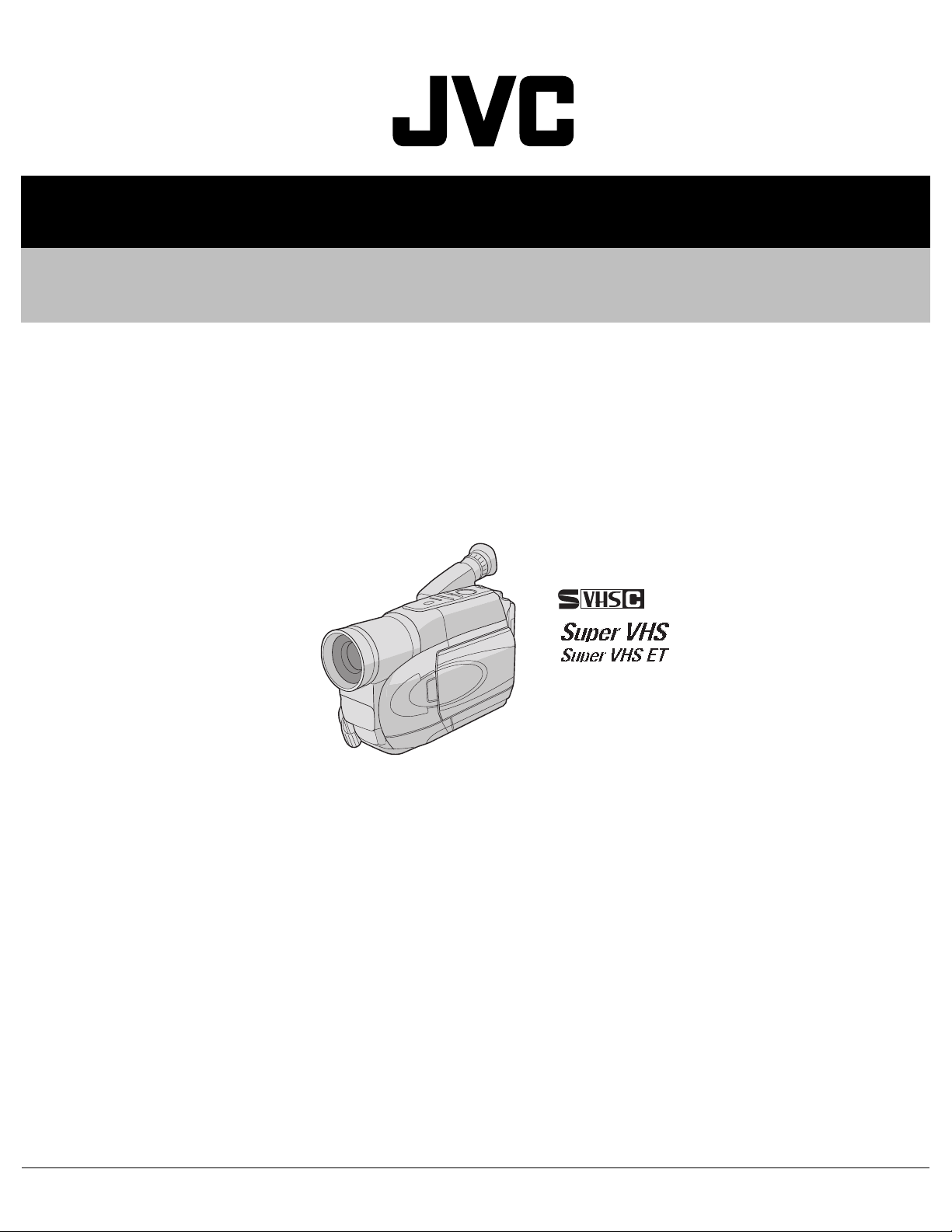
SERVICE MANUAL
COMPACT VHS CAMCORDER
YF00620041
GR-FXM40EK,GR-FXM40EX,GR-FXM40EY,
GR-FXM40EZ,GR-FXM404EX,GR-FXM404EY,
GR-FXM404EZ,GR-SXM30EF,GR-SXM50EX,
GR-SXM50EY,GR-SXM50EZ
VHS
PAL
625
GR-FXM40EK/EX/EY/EZ [M4A622], GR-FXM404EX/EY/EZ [M4A623]
GR-SXM30EF [M4C622], GR-SXM50EX/EY/EZ [M4C723]
For disassembling and assembling of MECHANISM ASSEMBLY, refer to the SERVICE MANUAL No.86700 (MECHANISM ASSEMBLY).
TABLE OF CONTENTS
1 PRECAUTION. . . . . . . . . . . . . . . . . . . . . . . . . . . . . . . . . . . . . . . . . . . . . . . . . . . . . . . . . . . . . . . . . . . . . . . . . 1-3
2 SPECIFIC SERVICE INSTRUCTIONS. . . . . . . . . . . . . . . . . . . . . . . . . . . . . . . . . . . . . . . . . . . . . . . . . . . . . . 1-5
3 DISASSEMBLY . . . . . . . . . . . . . . . . . . . . . . . . . . . . . . . . . . . . . . . . . . . . . . . . . . . . . . . . . . . . . . . . . . . . . . . 1-6
4 ADJUSTMENT . . . . . . . . . . . . . . . . . . . . . . . . . . . . . . . . . . . . . . . . . . . . . . . . . . . . . . . . . . . . . . . . . . . . . . . 1-15
5 TROUBLESHOOTING . . . . . . . . . . . . . . . . . . . . . . . . . . . . . . . . . . . . . . . . . . . . . . . . . . . . . . . . . . . . . . . . . 1-21
COPYRIGHT © 2004 VICTOR COMPANY OF JAPAN, LIMITED
No.YF006
2004/1
Page 2
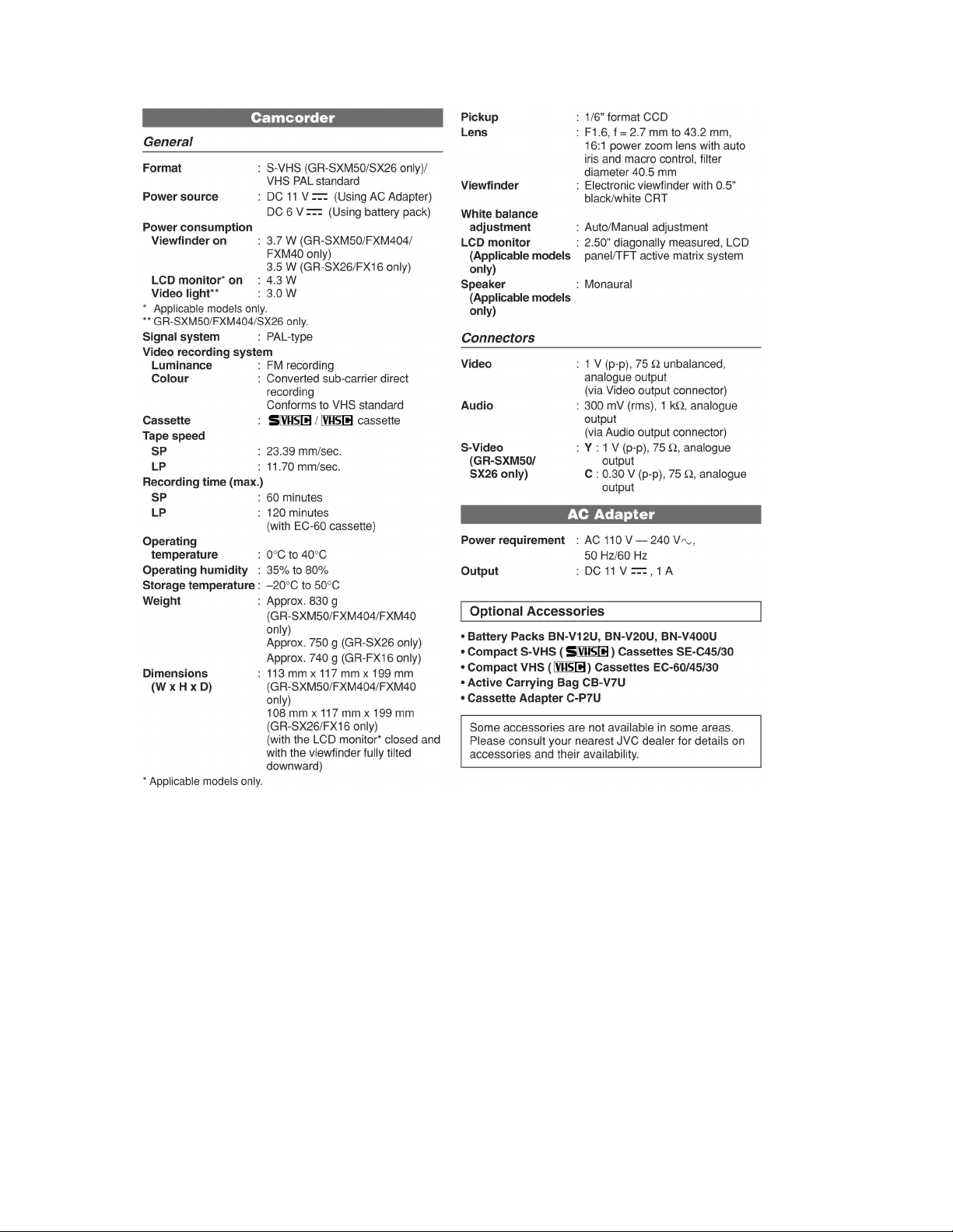
SPECIFICATION
1-2 (No.YF006)
Page 3
SECTION 1
r
e
PRECAUTION
1.1 SAFTY PRECAUTIONS
Prior to shipment from the factory, JVC products are strictly
inspected to conform with the recognized product safety and
electrical codes of the countries in which they are to be
sold.However,in order to maintain such compliance, it is equally
important to implement the following precautions when a set is
being serviced.
1.1.1 Precautions during Servicing
(1) Locations requiring special cauti on are denoted by labels
and inscriptions on the cabinet, chassis and certain parts of
the product.When performing service, be sure to read and
comply with these and other cautionary notices appearing
in the operation and service manuals.
(2) Parts identified by the symbol and shaded ( ) parts
are critical for safety.
Replace only with specified part numbers.
NOTE :
Parts in this category also include those specified to
comply with X-ray emission standards for products
using cathode ray tubes and those specified for
compliance with various regulations regarding
spurious radiation emission.
(3) Fuse replacement caution notice.
Caution for continued protection against fire hazard.
Replace only with same type and rated fuse(s) as
specified.
(4) Use specified internal wiring. Note especially:
• Wires covered with PVC tubing
• Double insulated wires
• High voltage leads
(5) Use specified insulating materials for hazardous live parts.
Note especially:
• Insulation Tape
• PVC tubing
•Spacers
• Insulation sheets for transistors
•Barrier
(6) When replacing AC primary side compon ents (transformers,
power cords, noise blocking capacitors, etc.) wrap ends of
wires securely about the terminals before soldering.
emission. Consequently, when servicing these products,
replace the cathode ray tubes and other parts with only the
specified parts. Under no circumstances attempt to modify
these circuits.Unauthorized modification can increase the
high voltage value and cause X-ray emission from the
cathode ray tube.
(12) Crimp type wire connectorIn such cases as when replacing
the power transformer in sets where the connections
between the power cord and power trans former primary
lead wires are performed using crimp type connectors, if
replacing the connectors is unavoidable, in order to prevent
safety hazards, perform carefully and precisely according
to the following steps.
• Connector part number :E03830-001
• Required tool : Connector crimping tool of the proper
type which will not damage insulated parts.
• Replacement procedure
a) Remove the old connector by cutting the wires at a
point close to the connector.Important : Do not
reuse a connector (discard it).
cut close to connector
Fig.1-1-3
b) Strip about 15 mm of the insulati on from the ends
of the wires. If the wires are stranded, twist the
strands to avoid frayed conductors.
15 mm
Fig.1-1-4
c) Align the lengths of the wires to be connected.
Insert the wires fully into the connector.
Metal sleeve
Fig.1-1-1
(7) Observe that wires do not contact heat producing parts
(heatsinks, oxide metal film resistors, fusible resistors, etc.)
(8) Check that replaced wires do not contact sharp edged or
pointed parts.
(9) When a power cord has been replaced, check that 10-15
kg of force in any direction will not loosen it.
Power cord
Fig.1-1-2
(10) Also check areas surrounding repaired locations.
(11) Products using cathode ray tubes (CRTs)In regard to such
products, the cathode ray tubes themselves, the high
voltage circuits, and related circuits are specified for
compliance with recognized codes pertaining to X-ray
Connector
Fig.1-1-5
d) As sh ow n in Fi g. 1-1-6, use the crimping tool to crimp
the metal sleeve at the center position. Be sure to
crimp fully to the complete closure of the tool.
1.2
5
2
.0
5.5
Crimping tool
Fig.1-1-6
e) Check the four points noted in Fig.1-1-7.
Not easily pulled free
Wire insulation recessed
more than 4 mm
Crimped at approx. cente
of metal sleev
Conductors extended
Fig.1-1-7
(No.YF006)1-3
Page 4
1.1.2 Safety Check after Servicing
Examine the area surrounding the repaired location for d amage
or deterioration. Observe that screws, parts and wires have been
returned to original positions, Afterwards, perform the following
tests and confirm the specified values in order to verify
compliance with safety standards.
(1) Insulation resistance test
Confirm the specified insulation resistance or greater
between power cord plug prongs and externally exposed
parts of the set (RF terminals, antenna terminals, video and
audio input and output terminals, microphone jacks,
earphone jacks, etc.).See table 1 below.
(2) Dielectric strength test
Confirm specified dielectric strength or greater between
power cord plug prongs and exposed accessible parts of
the set (RF terminals, antenna terminals, video and audio
input and output terminals, microphone jacks, earphone
jacks, etc.). See Fig.1-1-11 below.
(3) Clearance distance
When replacing primary circuit components, confirm
specified clearance distance (d), (d') between soldered
terminals, and between terminals and surrounding metallic
parts. See Fig.1-1-11 below.
d
Chassis
d'
Power cord
primary wire
Fig.1-1-8
(4) Leakage current test
Confirm specified or lower leakage current between earth
ground/power cord plug prongs and externally exposed
accessible parts (RF terminals, antenna terminals, video
and audio input and output terminals, microphone jacks,
earphone jacks, etc.).
Measuring Method : (Power ON)Insert load Z between
earth ground/power cord plug prongs and externally
exposed accessible parts. Use an AC voltmeter to
measure across both terminals of load Z. See Fig.1-1-9
and following Fig.1-1-12.
ab
Externally
exposed
accessible part
Z
V
c
A
Fig.1-1-9
(5) Grounding (Class 1 model only)
Confirm specified or lower grounding impedance between
earth pin in AC inlet and externally exposed accessible
parts (Video in, Video out, Audio in, Audio out or Fixing
screw etc.).Measuring Method:
Connect milli ohm meter between earth pin in AC inlet and
exposed accessible parts. See Fig.1-1-10 and grounding
specifications.
AC inlet
Earth pin
Exposed accessible part
MIlli ohm meter
Grounding Specifications
Region
USA & Canada
Europe & Australia
Grounding Impedance (Z
Z 0.1 ohm
Z 0.5 ohm
)
Fig.1-1-10
AC Line Voltage
100 V
100 to 240 V
110 to 130 V
110 to 130 V
200 to 240 V
Region
Japan
USA & Canada
Europe & Australia
Insulation Resistance (R
R 1 M /500 V DC
1 M R 12 M /500 V DC
R 10 M /500 V DC
)
Dielectric Strength
AC 1 kV 1 minute
AC 1.5 kV 1 minute
AC 1 kV 1 minute
AC 3 kV 1 minute
AC 1.5 kV 1 minute
(
Class
(
Class
Clearance Distance (d), (d'
d, d' 3 mm
d, d' 4 mm
d, d' 3.2 mm
d 4 mm
)
d' 8 mm (Power cord
d' 6 mm (Primary wire
)
Fig.1-1-11
AC Line Voltage
100 V
110 to 130 V
110 to 130 V
220 to 240 V
Region
Japan
USA & Canada
Europe & Australia
Load Z
1
0.15
1.5
2
50
Leakage Current (i)
i 1 mA rms
i 0.5 mA rms
i 0.7 mA peak
i 2 mA dc
i 0.7 mA peak
i 2 mA dc
a, b, c
Exposed accessible parts
Exposed accessible parts
Antenna earth terminals
Other terminals
Fig.1-1-12
NOTE :
These tables are unofficial and for reference only. Be sure to confirm the precise values for your particular country and locality.
)
)
)
1-4 (No.YF006)
Page 5
SECTION 2
SPECIFIC SERVICE INSTRUCTIONS
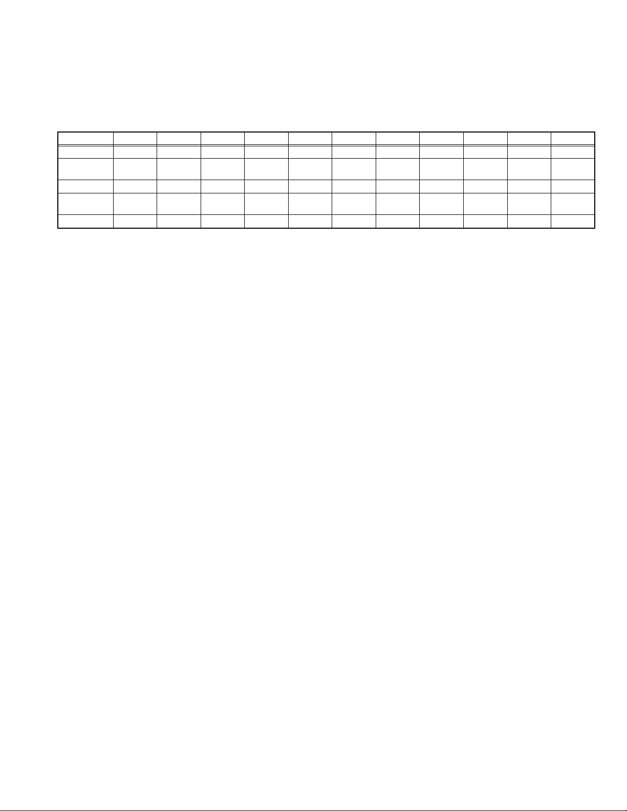
2.1 DIFFERENCE LIST The following table indicate main different points between models GR-FXM40EK, GR-FXM40EX, GR-FXM40EY, GR-FXM40EZ,
GR-FXM404EX, GR-FXM404EY, GR-FXM404EZ, GR-SXM30EF, GR-SXM50EX, GR-SXM50EY and GR-SXM50EZ.
MODEL
TAPE FORMAT
BODY COLOR SILVER SILVER SILVER SILVER MO LD
DC LIGHT NO NO NO NO YES YES YES NO YES YES YES
OSD LANGUAGE
AC CORD BS PLUG CEE PLUG CEE PLUG CEE PLUG CEE PLUG CEE PLUG CEE PLUG CEE PLUG CEE PLUG CEE PLUG CEE PLUG
GR-FXM40EK GR-FXM40EX GR-FXM40EY GR-FXM40EZ
VHS-C VHS-C VHS-C VHS-C VHS-C VHS-C VHS-C S-VHS-C S-VHS-C S-VHS-C S-VHS-C
ENGLISH ENGLISH/
RUSSIAN
ENGLISH/
RUSSIAN
ENGLISH/
RUSSIAN
GR-FXM404EX GR-FXM404EY
BLACK
ENGLISH/
RUSSIAN
MOLD
BLACK
ENGLISH/
RUSSIAN
GR-FXM404EZ GR-SXM30EF GR-SXM50EX GR-SXM50EY GR-SXM50EZ
MOLD
BLACK
ENGLISH/
RUSSIAN
MOLD
BLACK
ENGLISH ENGLISH/
SILVER SILVER SILVER
RUSSIAN
ENGLISH/
RUSSIAN
ENGLISH/
RUSSIAN
(No.YF006)1-5
Page 6
SECTION 3
DISASSEMBLY
3.1 BEFORE ASSEMBLY AND DISASSEMBLY
3.1.1 Precautions
• Be sure to disconnect the power supply unit prior to mounting
and soldering of parts.
• Prior to removing a component part that needs to disconnect
its connector(s) and its screw(s), first disconnect the wire(s)
from the connector(s), and then remove the screw(s).
• When connecting/disconnecting wires, pay enough attention
not to damage the connectors.
• When inserting the flat wire to the connector, pay attention to
the direction of the flat wire.
• Be careful in removing the parts to which some spacer or
shield is attached for reinforcement or insulation.
• When replacing chip parts (especially IC parts), first remove
the solder completely to prevent peeling of the pattern.
• Tighten screws properly during the procedures. Unless
specified otherwise, tighten screws at a torque of 0.196N
·cm). However, 0.196N·m (2.0kgf·cm) is a value at the
(2.0kgf
time of production. At the time of service, perform the
procedure at a torque 10% less than 0.196N
·m (2.0kgf·cm).
(See "SERVICE NOTE" as for tightening torque.)
3.1.2 Destination of connectors
Two kinds of double-arrows in connection tables respectively
show kinds of connector/wires.
: Wire: Flat wire : Board to board (B-B)
: The connector of the side to remove
CONN. No. PIN No.CONNECTOR
CN2a
CN2b
MAIN CN101
MAIN CN103
MONI/ BW CN761
MIC CN762
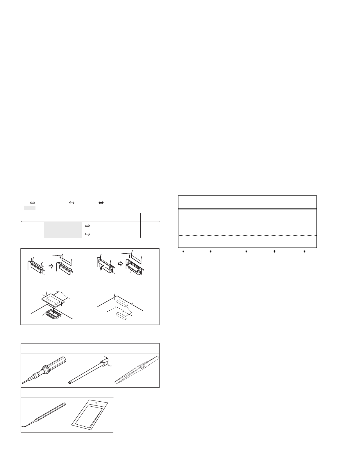
3.1.3 Disconnection of connectors (Wires)
Wire
· Pull both ends of the connector in the arrow
direction, remove the lock and disconnect the flat
wire.
B-B Connector
B-B Connector
· Pull the both ends of the board in the direction of the arrow, and remove the B-B Connector.
FPC Connector
· Extend the locks in the direction of the arrow for
unlocking and then pull out the wire. After
removing the wire, immediately restore the locks
to their original positions because the locks are
apt to come off the connector.
Wire
FPC Connector
Lock
B-B Connector
Fig.3-1-1
3.1.4 Tools required for disassembly and assembly
Torque driver
YTU94088
Chip IC replacement jig
PTS40844-2
Bit
YTU94088-003
Cleaning cloth
KSMM-01
Tweezers
P-895
·m
40
2
• Torque driver
Be sure to use to fastening the mechanism and exterior parts
because those parts must strictly be controlled for tightening
torque.
• Bit
This bit is slightly longer than those set in conventional torque
drivers.
• Tweezers
To be used for removing and installing parts and wires.
• Chip IC replacement jig
To be used for replacement of IC.
• Cleaning cloth
Recommended cleaning cloth to wipe down the video heads,
mechanism (tape transport system), optical lens surface.
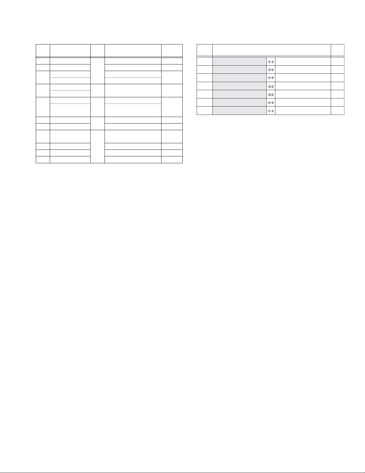
3.2 ASSEMBLY AND DISASSEMBLY OF MAIN PARTS
3.2.1 Assembly and disassembly
When reassembling, perform the step(s) in reverse order.
STEP
No.
[1]
[2]
[8]
PART
TOP COVER ASSY
UPPER ASSY
(Inc. VF ASSY,
SPEAKER/MONITOR)
VF ASSY
(∗1) Order of steps in Procedure
When reassembling, preform th e step(s) in the reverseorder.
These numbers are also used as the identification (location)
No. of parts Figures.
(∗2) Part to be removed or installed.
(∗3) Fig. No. showing Procedure or Part Location.
C = CABINET
(∗4) Identification of part to be removed, unhooked, unlocked,
released, unplugged, unclamped or unsoldered.
S = Screw
L = Lock, Release, Hook
SD = Solder
CN = Connector
[Example]
• 4 (S1a) = Remove 4 S1a screws.
• 3 (L1a) = Disengage 3 L1a hooks.
• 2 (SD1a) = Unsolder 2 SD1a points.
• CN1a = Remove a CN1a connector.
(∗5) Adjustment information for installation.
Fig.
No.
Fig.C1
Fig.C2-1
Fig.C2-2
POINT
S1,2(L1)
S2a,2(S2b),3(S2c)
2(S2d),S2e,S2c
L2,CN2a,b
2(S8),L8,CN8a
( 4) ( 5)( 2) ( 3)( 1)
NOTE
-
-
NOTE 8a
NOTE 8b
1-6 (No.YF006)
Fig.3-1-2
Page 7
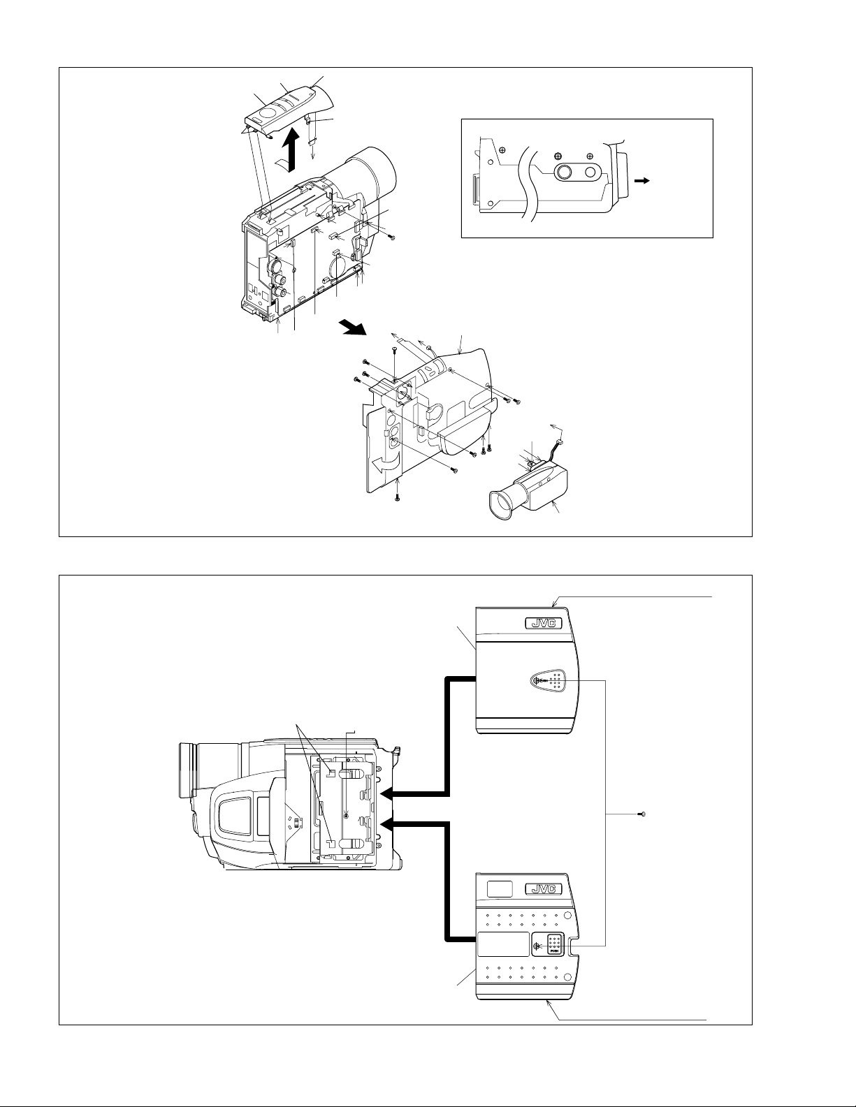
3.2.2 ASSEMBLY/DISASSEMBLY OF CABINET PARTS AND ELECTRICAL PARTS
zDisassembly procedure
STEP
PART NAME
No.
[1]
LOWER CASE ASSEMBLY
[2]
B/W VF ASSEMBLY
[3]
TOP OPE UNIT(S)
TOP OPE UNIT(M)
[4]
CASE COVER(S) ASSEMBLY
CASE COVER(M) ASSEMBLY
[5]
UPPER CASE(S) ASSEMBLY
UPPER CASE(M) ASSEMBLY
Inc. MONITOR ASSEMBLY
[6]
COVER (UPPER/M) ASSEMBLY
[7]
MONITOR ASSEMBLY
[8]
FRONT COVER ASSEMBLY
Inc. DC LIGHT,MIC
[9]
DC LIGHT ASSEMBLY
[10]
MIC
[11]
FRONT FRAME SA
Fig.C1
Fig.C2
Fig.C3
Fig.C4
Fig.C5
Fig.
No.
8(S1),CN1a,b,c
3(S2)
CN3,(S3),(L3a),(L3b),2(L3d)
CN3,(S3),(L3a),(L3b),(L3c),2(L3d)
(S4),2(L4)
6(S5a),(S5b),(L5)
CN5,6(S5a),(S5b)
3(S6)
S7a,L7,SHEET(FPC),2(S7b)
CN8a,CN8b,(S8),L8a,L8b
2(L9)
S10
2(S11)
POINT NOTE
-
-
-
-
NOTE 5
-
NOTE 7a,b,c,d
NOTE 8a,b
-
-
-
zDestination of connectors
CN.NO.
CN1a MAIN CN27 SPEAKER - 2
CN1b MAIN CN13 ZOOM UNIT - 14
CN1c MAIN CN12 B/W VF ASSEMBLY - 3
CN3 MAIN CN18 TOP OPE UNIT - 13
CN5 MAIN CN16
CN8a MAIN CN6 DC LIGHT - 2
CN8b MAIN CN8 MIC - 2
NOTE 5 :
Take care not to break or damage the FRAME.
NOTE 7a :
Take care not to cut the FPC wire.
NOTE 7b :
Insert and attach the SHEET(FPC) between the MONITOR
FPC and the UPPER CASE(M)ASSEMBLY.
NOTE 7c :
Attachment of the FPC
NOTE 7d :
For disassembly of the MONITOR ASSEMBLY, refer to 2.4
ASSEMBLY AND DISASSEMBLY OF [7]MONITOR ASSEMBLY (CABINET PARTS).
NOTE 8a :
Take care not to damage the OP BLOCK ASSEMBLY when
and after the FRONT CASE ASSEMBLY is removed.
NOTE 8b :
Attachment of the WIRE
CONNECTOR
MONITOR ASSEMBLY
CN7601
PIN
NO.
25
(No.YF006)1-7
Page 8
[3]
L3c
L3b
L3d
E
x
CN1c
u
t
CN1b
D
F
CN1a
10 (S2
11 (S2
L3a
v
D
9 (S2
)
<BOTTOM SIDE>
6
78
OP BLOCK
ASSEMBLY
CN3
w
12
(S3)
G
z
y
5
(S1)
v
[1]
4
(S1)
w
y
7
(S1)
z
8
(S1)
2
(S1)
p
q
(S1)
s1
r
1
E
F
G
3
(S1)
)
r
)
s1
q
p
E
u
t
x
6
(S1)
[2]
Fig.C1
L4
<S : SHOOTING MODEL>
[4]
aa
aa
12
(S4)
aa
[4]
1-8 (No.YF006)
<M : MONITOR MODEL>
Fig.C2
Page 9

<NOTE 5>
[5]
15
(S5a)
16
(S5a)
14
(S5a)
n
m
<S : SHOOTING MODEL>
g
k
k
24
(S7b)
25
(S7b)
[7]
<NOTE 7d>
<NOTE 5>
[5]
15
(S5a)
16
(S5a)
e
l
j
17
(S5a)
h
i
j
17
(S5a)
FPC
<NOTE 7a>
23
(S7a)
14
(S5a)
n
m
k
18
(S5a)
[6]
f
d
c
L7
<NOTE 7b>
SHEET(FPC)
18
(S5a)
g
h
i
e
<M : MONITOR MODEL>
19
(S5b)
n
C
(L5)
c
d
j
Fig.C3
f
d
c
20
(S6)
21
(S6)
22
(S6)
m
13
(S5a)
g
C
CN5
k
<MONITOR MODEL>
<NOTE 7c>
DO NOT MAKE FPC
SLACKEN IN THIS PART.
PROCESSED
THROUGH THIS PART.
UPPER CASE(M)ASSEMBLY
AS FOR PUSH SW, DON'T BE
BROKEN AND DON'T FLOAT .
(SEE AND CHECK SW AFTER
ATTACHING FPC.)
Fig.C4
INSTALL THE RAINFORCEMENT
BOARD WITH MONITOR OPENED .
( FOR THE DAMAGE PREVENTION
OF PUSH SWITCH .)
(No.YF006)1-9
Page 10

28
(S11)
26
(S8)
0.118N.m (1.2kgf.cm)
[11]
a
OP BLOCK ASSEMBLY
29
(S11)
b
b
SCREWING SEQUENCE
SHOULD BE IN ORDER
HERE FIRST AND OTHERS .
<NOTE 8a>
L8a
c
a
SHIELD
CN8b
c
[8]
L8b
A
B
CN8a
A
B
LIGHT WIRE
SHIELD SHEET
SHOULD BE PUTTED SHIELD
PLATE BETWEEN FRAME TO MECHA .
<NOTE 8b>
MIC WIRE
PASS THE WIRE
BETWEEN
THESE BOSSES.
DO NOT OBSTRUCT
THE RECEIVING
PART OF SENSOR
BY WIRE .
PASS THE WIRE
OUTSIDE OF
THIS BOSS .
[9]
27
(S10)
L9
[10]
Fig.C5
1-10 (No.YF006)
Page 11

3.2.3 ASSEMBLY AND DISASSEMBLY OF CAMERA SECTION AND BOARD ASSEMBLY
zDisassembly procedure
STEP
No.
[1]
[2]
[3]
[4]
[5]
PART
MAIN BOARD ASSEMBLY
OP BLOCK ASSEMBLY
CCD BOARD ASSEMBLY
MECHANISM ASSEMBLY
REAR BOARD ASSEMBLY
Fig.
No.
Fig.D1
Fig.D2
Fig.D3
Fig.D4
POINT
CN1a,b,c,d,e,f,g,h,SHIELD
2(S1),L1,CN1j
2(S2)
(S4a),(S4b),L4
SHIELD CASE(MAIN)
2(S4c),(S4d)
2(S5)
NOTE 3 :
For disassembly of the CCD BOARD ASSEMBLY, refer to
2.5 ASSEMBLY AND DISASSEMBLY OF [2]OP BLOCK
ASSEMBLY CCD BOARD ASSEMBLY (CAMERA SECTION AND BOARD ASSEMBLY).
NOTE 4 :
When attaching the MECHANISM ASSEMBLY to S.CASE
(MAIN), pull out the FPC CABLE not to be inserted between
the MECHANISM ASSEMBLY and S.CASE (MAIN).
zDestination of connectors
CONN.
No.
CN1a
CN1b
CN1c
CN1d
CN1e
CN1f
CN1g
CN1h
CN1j
MAIN CN15
MAIN CN4
MAIN CN1
MAIN CN5
MAIN CN2
MAIN CN3
MAIN CN7
MAIN CN22
MAIN CN28
CONNECTOR
OP BLOCK
LOADING MOTOR
DRUM MOTOR
HEAD(VIDEO,FLY.E)
SENSOR
CAPSTAN MOTOR
A/C HEAD
CCD
REAR UNIT
ASSEMBLY
CN5301
-
-
-
-
-
-
-
-
NOTE
-
-
NOTE 3
NOTE 4
-
Pin No.
24
2
10
11
14
18
11
14
10
(No.YF006)1-11
Page 12

A2
G2
CN1j
F2
A2
B2
J
D2
CN1e
SHIELD
C2
G2
L1
CN1f
E2
CN1g
B2
F2
CN1h
J
C2
D2
CN1d
2
(S1)
E2
(S1)
[1]
CN1a
CN1c
1
CN1b
9
(S4d)
d
[4]
g
c
8
(S4c)
7
(S4c)
FRAME ASSEMBLY
e
c
<NOTE 4>
e
SHIELD
CASE
(MAIN)
g
d
f
G1
G2
L4
5
(S4a)
6
(S4b)
4
(S2)
3
(S2)
Fig.D1
h
h
j
j
[3]
<NOTE 3>
[2]
Fig.D3
[5]
a
b
a
10
(S5)
b
11
(S5)
FRAME
ASSEMBLY
1-12 (No.YF006)
Fig.D2
Fig.D4
Page 13

3.2.4 ASSEMBLY AND DISASSEMBLY OF [7]MONITOR ASSEMBLY (CABINET PARTS)
zDisassembly of MONITOR ASSEMBLY
NOTE :
Be careful not to soil or scratch the monitor screen through
the disassembly/assembly work.
(1) While removing the th ree screws 1 to 3 in numerical
order and disengaging the three hooks (L7a and L7b)
in alphabetical order, remove the MONITOR COVER
ASSEMBLY.
NOTE 7a :
After removing the MONITOR COVER ASSEMBLY,
MONITOR COVER
ASSEMBLY
<NOTE 7b>
CN7a
be careful not to damage the FPC and the connector
because the MONI. HINGE ASSEMBLY moves
very easily.
(2) Unlock the conne ctor 7a and then remove the FPC
while lifting the MONI. HINGE ASSEMBLY upwards to
MONITOR BOARD
ASSEMBLY
4
(S7a)
remove it together with the FPC.
NOTE 7b :
D1
When removing the FPC, unlock the connector first
and then lift the MONI. HINGE ASSEMBLY upwards. Accordingly, the FPC is removed together
with the MONI.HINGE ASSEMBLY.
(3) Unsolder the two soldered parts (SD7).
NOTE 7c :
When removing the MONITOR BOARD ASSEMBLY and the BACKLIGHT together, it is not necessary to unsolder the two soldered parts (SD7).
NOTE 7d :
It depends on the inch size of the monitor assembly
whether the backlight is supplied as an assembly or
as separated parts.
In replacing the backlight assembly, see the Parts
MONI. HINGE
ASSEMBLY
List.
(4) Unlock the connector 7b, and disconnect the FPC
from the connector 7b.
(5) Disconnect the FPC from MONITOR CASE ASSEM-
BLY.
(6) Remove the screw (4), and remove the MONITOR
BOARD ASSEMBLY while lifting the side of MONITOR BOARD ASSEMBLY which has been attached
with screw (4) upwards.
(7) Remove the BACKLIGHT and DIFF SHEET in this or-
der.
(8) Remove the SPACER(LCD) and LCD MODULE in this
order.
D1
(9) Remove the S.CASE while disengaging L7e and L7f at
the both sides of MONITOR CASE ASSEMBLY.
L7c
L7e
L7a
<NOTE 7c>
C1
E1
L7f
L7b
<NOTE 7b>
CN7b
B1
SD7
E1
B1
C1
F1
MONITOR CASE ASSEMBLY
BACKLIGHT
ASSEMBLY
DIFF SHEET
SHOULD PUT THIS
PART AT RIGHT SIDE .
SPACER(LCD)
LCD MODULE
A1
S.CASE
1
(S7a)
F1
A1
<NOTE 7d>
L7d
2
(S7b)
3
(S7b)
Fig.3-2-1
(No.YF006)1-13
Page 14

3.2.5 ASSEMBLY AND DISASSEMBLY OF [2]OP BLOCK ASSEMBLY
CCD BOARD ASSEMBLY (CAMERA SECTION AND BOARD ASSEMBLY)
zPrecautions
(1) Take care in handling the CCD IMAGE SENSOR, OP
zAssembly of CCD BASE ASSEMBLY and CCD BOARD AS-
SEMBLY
LPF and lens components when performing maintenance etc., especially with regard to surface contamination, attached dust or scratching. If fingerprints are
present on the surface they should be wiped away using
either a silicon paper, clean chamois or the cleaning
cloth.
(2) The CCD IMAGE SENSOR may have been shipped with
a protective sheet attached to the transmitting glass.
When replacing the CCD IMAGE SENSOR, do not peel
off this sheet from the new part until immediately before
it is mounted in the OP BLOCK ASSEMBLY.
(3) The orientation of the OP LP F is an important factor for
installation. If there is some marking on the OP LPF, be
sure to note it down before removing and to reassemble
it very carefully as it was referring to the marking.
zDisassembly of CCD BOARD ASSEMBLY and CCD BASE
ASSEMBLY
(1) Unsolder the CCD BOARD ASSEMBLY by the 14 points
zReplacement of service repair parts
The service repair parts for the OP BLOCK ASSEMBLY are as
listed below.
Before replacement of these parts, remove the BRACKET (OP
BLOCK ASSEMBLY) as required.
Take special care not to disconnect any of the FPC wires or
cause any damage due to soldering (excessive heating).
(SD2) and then remove it.
(2) Remove the two screws (1, 2) and remove the CCD
BASE ASSEMBLY.
(3) Remove the SPACER.
NOTE 2b:
(4) Remove the SHEET.
(5) Remove the OP LPF.
NOTE 2c:
(1) Set the OP LPF to the OP BLOCK ASSEMBLY so that
the OP side touches the OP BLOCK ASSEMBLY.
NOTE 2a:
Pay careful attention to the orientation of the OP LPF.
(2) Set the SHEET to the OP LPF not to come off the right
position.
(3) Attach the SPACER to the OP BLOCK ASSEMBLY.
(4) Fasten them together with the two screws (1, 2).
(5) Set the CCD BOARD ASSEMBLY in the CCD BASE AS-
SEMBLY, and then solder it by the 14 points (SD2).
(1) FOCUS MOTOR
(2) ZOOM MOTOR
(3) IRIS MOTOR UNIT
When replacing the FOCUS MOTOR or the ZOOM MOTOR, solder the FPC at a space of about 1 mm above the
terminal pin.
The IRIS MOTOR UNIT includes the FPC ASSEMBLY and
two sensors.
(S2c)
8
(S2c)
SENSOR
1
11
9
(S2c)
(S2c)
7
IRIS MOTOR UNIT
<NOTE 2b, c>
10
(S2c)
5
(S2b)
OP BLOCK
6
(S2b)
FOCUS MOTOR
<NOTE 2b>
(S2b)
3
<NOTE 2a>
OP LPF
Blue
OP
side
4
(S2b)
CCD
side
OP LPF
ZOOM MOTOR
<NOTE 2b>
(SD2)
SHEET
CCD BASE ASSEMBLY
SPACER
0.078N.m (0.8kgf.cm)
.
m (1.2kgf.cm)
0.118N
(S2a)
2
(S2a)
CCD BAORD
ASSEMBLY
1-14 (No.YF006)
Fig.3-2-2
Page 15

SECTION 4
ADJUSTMENT
4.1 PREPARATION
4.1.1 Precaution
Camera system and deck system of this model are specially
adjusted by using PC.
However, if parts such as the following are replaced, an
adjustment is required. The adjus tment must be performed in a
Service Center equipped with the concerned facilities.
• OP BLOCK ASSEMBLY
• EEP ROM (IC102 of MAIN board)
• MONITOR
In the event of malfunction with electrical circuits, first find a
defective portion with the aid of proper test instruments as shown
in the following electrical adjustment procedure, and then
commence necessary repair/ replacement/adjustment.
• In observing chip TP, use IC clips, etc. to avoid any stress.
Prior to replacement of chip parts (especially IC), remove the
solder completely to prevent peeling of the pattern.
• Use a patch cord if necessary. As for a patch cord, see the
BOARD INTERCONNECTIONS.
• Since connectors are fragile, carefully handle them in
disconnecting and connecting the FPC.
4.1.2 REQUIRED TEST EQUIPMENT
• Personal computer (for Windows)
• Color TV monitor
• Oscilloscope (dual-trace type, observable 100MHz or higher
frequency). The one observable 300 MHz or higher frequency
is recommended.
• Digital voltmeter
• DC power supply or AC adapter
• Frequency counter (with threshold level adjuster)
4.1.3 TOOLS REQUIRED FOR ADJUSTMENT
Alignment tape
MHPE-C
Roller driver
PTU94002-2
INF Adjustment Lens
YTU92001B
Light box Assembly
YTU93096A
Jig Connector Cable
YTU93082G
Alignment tape
MHPE-LC
Cleaning Cloth
KSMM-01
INF Adjustment Lens Holder
YTU94087
Gray Scale Chart
YTU94133A
PC Cable
QAM0099-005
Cassette torque meter
PUJ50431-2
YTU92001-111
Camera Stand
YTU93079
Color Bar Chart
YTU94133C
Communication Cable
YTU93107A
Conn. ring
Service Support System
YTU94057-78
• Alignment tape
To be used for check and adjustment of interchangeability of
the mechanism.
(Video: Color bar signal, Audio: Non-signal)
• Cassette torque meter
This is used to cheek the back tension and play torque during
mechanism adjustment.
• Roller driver
To be used to turn the Roller driver to adjustment of the linearity of playback envelope.
• Cleaning Cloth
Recommended the Cleaning cloth to wipe down the video
heads, mechanism (tape transport system), optical lens surface.
(No.YF006)1-15
Page 16

• Conn. ring
The connector ring to attach the INF lens to the head of the OP
lens. For the usage of the Conn.ring.
• INF Adjustment Lens
To be used for adjustment of the camera system. For the usage of the INF adjustment lens, refer to the Service Bulletin
No. YA-SB-10035.
• INF Adjustment Lens Holder
To be used together with the Camera stand (11) for operating
the Videocamera in the stripped-down condition such as the
status without the exterior parts or for using commoditie s that
are not yet conformable to the interchangeable ring. For the
usage of the INF lens holder, refer to the Service Bulletin No.
YA-SB-10035.
• Camera Stand
To be used together with the INF adjustment lens holder. For
the usage of the Camera stand, refer to the Service Bulletin
No. YA-SB-10035.
• Light box Assembly
To be used for adjustment of the camera system. For the usage of the Light box assembly, refer to the Service Bulletin No.
YA-SB-10035.
• Gray Scale Chart
To be used for adjustment of the camera system. For the usage of the INF adjustment lens, refer to the Service Bulletin
No. YA-SB-10035.
• Color Bar Chart
To be used for adjustment of the camera system. For the usage of the INF adjustment lens, refer to the Service Bulletin
No. YA-SB-10035.
• Jig Connector Cable
To be connected to the Jig connector jack of the main board
and used for measurement and adjustment.
• PC Cable
To be used to connect the Videocamera and a personal computer with each other when a personal computer issued for adjustment.
• Communication Cable
Connect the Communication cable between the PC cable and
Jig connector cable when performing a PC adjustment.
• Service Support System
To be used for adjustment with a personal computer. Software
can be downloaded also from JS-net.
4.2 JIG CONNECTOR CABLE CONNECTION Connection procedure
JIG CONNECTOR
CABLE
CN25
JIG CONNECTOR COMMUNICATION CABLE
TO 8 PIN
( RXD )
RED
TO 7 PIN
( TXD )
( GND )
WHITE
BLACK
SERVICE SUPPORT SYSTEM
RS232C
COM PORT
PERSONAL COMPUTER
MENU
TO 6 OR 16 PIN
Fig.4-2-1
Jig connector diagrams
JIG CONNECTOR CABLE (YTU93082G)
MAIN CN25 JIG BOARD (LABEL)
AL_J3.2V 1 1 AL_J3.2V
MCU_RST 11 2 BWVFADJ
BWVFADJ 2 3 DIAL_PB
V_TP_FM 12 4 DIAL_MN
DIAL_PB 3 5 JIGCN_SW
V_FF 13 6 GND
DIAL_MN 4 7 TXD
EJECT_SW 14 8 RXD
JIGCN_SW 5 9 PLI_AD
PB_CTL 15 10 VPP_7.8V
GND 6 11 MCU_RST
GND 16 12 V_TP_FM
TXD 7 13 V_FF
V_OUT 17 14 EJECT_SW
RXD 8 15 PB_CTL
AO_SIG_J 18 16 GND
PLI_AD 9 17 V_OUT
V_OVL 19 18 AO_SIG_J
VPP_7.8V 10 19 V_OVL
DISCHG_L 20 20 DISCHG_L
COVER(JIG)
PC CABLE
1-16 (No.YF006)
Fig.4-2-2
Page 17

4.3 MECHANISM COMPATIBILITY ADJUSTMENT
4.3.1 Tape transport adjustment
Mechanism adjustment is needed when DRUM ASSEMBLY or a
part of the tape transport system is replaced. To protect tapes
from damage, first clean the tape transport system, next confirm
that nothing is wrong with the tape transport system by using a
tape that can be disposed of, and then perform adjustment with
alignment tape. Some exterior parts should be removed before
some adjustment procedures, depending on the procedures.
BACK TENSION
0.97x10
-3
- 1.71x10⁻³ N•m
(10-17gf·cm)
PLAY TORQUE
1.47x10
-3
- 2.45x10⁻³ N·m
(15-25gf·cm)
POLE BASE (SUP)
(GUIDE ROLLER)
POLE BASE (TU)
(GUIDE ROLLER)
TU GUIDE
POLE
A/C HEAD
ASSEMBLY
TENSION
POLE
PINCH
ROLLER
Fig.4-3-1
4.3.2 Back tension
Remove the exterior parts attached to CASSETTE HOUSING
ASSEMBLY so that scales of CASSETTE TORQUE METER can
be read.
• CASE COVER(S),(M) ASSEMBLY
• C. COVER INSIDE
Fig.4-3-3
4.3.3 Tape pattern
Remove the exterior parts attached to the UPPER CASE
ASSEMBLY so that the guide roller beside the DRUM ASSEMBLY
can be rotated.
• LOWER CASE ASSEMBLY
• TOP OPE UNIT
• CASE COVER(S),(M) ASSEMBLY
• UPPER CASE (S),(M) ASSEMBLY
NOTE:
In performing adjustment, it is recommended that LOWER
CASE ASSEMBLY and TOP OPE UNIT are attached to the
main body for better operation and safety.
POLE BASE (TU)
(GUIDE ROLLER)
ALIGNMENT TAPE
CASSETTE TORQUE METER
Fig.4-3-2
(1) Set a cassette torque meter onto the deck and measure the
back tension in standard PB mode to confirm that the back
tension is 0.97x10
-3
- 1.71x10⁻³ N•m.
(2) If not, replace the tension band.
When the value widely fluctuates in the measurement,
replace the SUPPLY REEL DISK.
(3) With the CASSETTE TORQUE METER, confirm that the
play torque is 1.47x10
-3
- 2.45x10⁻³ N•m.
If necessary, replace the center pulley unit.
POLE BASE (SUP)
(GUIDE ROLLER)
JIG CONNECTOR CABLE
MAIN CN25 - JIG BOARD
12PIN(V_TP_FM)
13PIN(V_FF)
Fig.4-3-4
(1) Remove the Cover (JIG) shown on Fig.4-2-1.
(2) Connect the JIG CONNECTOR CABLE to CN25 on the
MAIN BOARD ASSEMBLY as shown on Fig. 4-2-2.
(3) Observe signal at V_TP_FM with external trigger from
V_FF on the JIG CONNECTOR CABLE.
(4) Playback the SP stairstep signal of the alignment tape and
maximize the FM waveform by the tracking button.
(5) Set the tracking con trol to the center position by simulta-
neously pressing the tracking (-) and (+) buttons and maximize the FM waveform by the tracking button.
(6) If the observed FM waveform is not flat, adjust the height of
the SUPPLY of TAKE-UP GUIDE ROLLER with the roller
driver.
NOTE:
To prevent the tape from damage, turn the guide rollers
slowly.
(No.YF006)1-17
Page 18

(7) By operating the tracking button (both in + and - directions)
in the manual tracking mode, vary the output level of the
FM waveform from maximum to minimum and vice versa to
confirm that the waveform varies nearly in a flat shape.
(8) When the FM waveform breaks in the level varying process,
subtly adjust the height of guide rollers at every breaking
point so that the waveform varies as flat as possible.
Repeat the above steps 6. and 7. several times to confirm
that the waveform is flat as a whole.
(9) Playback the SP stairstep signal of alighment tape and ad-
just the tracking control to maximize the FM waveform,
confirm that FM waveform variation is always flat.
(10) Record the signal and play it back in both of the SP and LP
modes, and confirm that the FM waveform is flat in both
modes.
NOTE:
Among the above-mentioned adjustment steps, the
items of No.9 and No.10 are needed for the LP model
only.
CH-2
1 field
FLATTEN WAVEFORM.
CAUSER BY WRONG HEIGHT
OF SUPPLY GUIDE ROLLER
CAUSED BY WRONG HEIGHT
OF TAKE-UP GUIDE ROLLER
4.3.4 A/C head height & azimuth
Remove the exterior parts attached to the UPPER CASE
ASSEMBLY so that the screws around the A/C HEAD
ASSEMBLY can be tighten or loosen.
• LOWER CASE ASSEMBLY
• TOP OPE UNIT
• CASE COVER(S),(M) ASSEMBLY
• UPPER CASE (S),(M) ASSEMBLY
• FRONT FRAME ASSEMBLY
NOTE:
In performing adjustment, it is recommended that LOWER
CASE ASSEMBLY and TOP OPE UNIT are attached to the
main body for better operation and safety.
(1) Remove the Cover (JIG) shown on Fig.4-2-1.
(2) Connect the JIG CONNECTOR CABLE to CN25 on the
MAIN BOARD ASSEMBLY.
(3) Connect the channel-1 scope probe to the audio output
(AO_SIG_J) and connect the channel-2 scope probe to PB
CTL.
(4) Playback the alignment tape.
(5) Set the tracking to its center range by pressing the (+) and
(-) tracking controls simultaneously.
(6) Adjust screws A , B and C approximately 45 degrees in the
same direction to obtain maximum audio o utput and CTL
signal levels.
(7) As a final fine adjustment, adjust screw B for minimum sig-
nal level fluctuation and screw C for maximum output sig-
nal level.
Fig.4-3-5
CORRECT VARIATION OF WAVEFORM
BAD VARIATION OF WAVEFORM
Fig.4-3-6
(11) Through the above steps, confirm that there occur no wrin-
kling and damage in the tape around the PINCH ROLLER
and TU GUIDE POLE whenever the deck is in operation of
Loading/Unloading, Search Rewind and at mode change
from Search Rewind to play mode. If wrinkling or damage
in the tape occurs around the TU GUIDE POLE, adjust the
angle (slant) of the A/C HEAD to the tape. So that the tape
normally runs along the lower flange of the GUIDE POLE.
SCREW A
A/C HEAD
SCREW C
SCREW B
Fig.4-3-7
Audio
signal
Control
pulse
signal
1-18 (No.YF006)
Fig.4-3-8
Page 19

4.3.5 Phase of control head (X value)
Note:
Remove the exterior parts attached to the UPPER CASE
ASSEMBLY so that the screws around the A/C HEAD
ASSEMBLY can be tighten or loosen.
(1) Connect the JIG CONNECTOR CABLE to CN25 on the
MAIN BOARD ASSEMBLY.
(2) Playback the SP stairstep signal of the alignment tape and
observe signal at V_TP_FM with external trigger from
V_FF on the JIG CONNECTOR CABLE.
(3) Operate the tracking button in the center and manual
tracking mode by pressing the tracking (+) and (-) buttons
and confirm that the FM output level is maximum at
the center position as shown in Fig. 4-3-10.
(4) If necessary, slightly loosen the setscrews D and E and
insert the Tweezers into the notch and guide hole to move
the A/C HEAD fully in the direction of the capstan to the
extent.
(5) Gradually move the A/C HEAD toward the drum to find the
position where the FM output level maximum for the first
time (A’ - B’ in Fig. 4-3-10).
(6) Fine adjust the phase of the A/C HEAD and tighten the
screws D and E at the point A.
A/C HEAD
INSERT THE
TWEEZERS
4.4 ELECTRICAL ADJUSTMENT
Electrical adjustment is performed by using a personal computer
and software for SERVICE SUPPORT SYSTEM. Read README.TXT file to use the software properly.
As for the connection of cables, see "4.2 JIG CONNECTOR
CABLE CONNECTION".
4.4.1 B/W VF ASSEMBLY (E. VF) ADJUSTMENT
Referring to “SEC. 3 DISASSEMBLY” and connect the E. VF
WIRE to CN12 of the MAIN BOARD ASSEMBLY.
(LY20701)
BOTTOM CASE ASSEMBLY
PARTS NO.
LY20701
Fig.4-4-1
NOTE:
• Unless otherwise specified, all measurement points and adjustment parts are located on E. VF BOARD ASSEMBLY.
• After adjustment or replacement of the deflection yoke o r the
centering magnet, fix it by the band as shown the figure below.
TOP VIEW
CRT
SERIAL NO. LABEL
SCREW
CENTERING
MAGNET
STOPPER
SCREW D
FM OUTPUT
DIRECTION OF CAPSTAN
Fig.4-3-9
A
ADJUSTING
POINT
A/C HEAD PHASE
Fig.4-3-10
SCREW E
B
DIRECTION OF DRUM
MAX
ZERO
Fig.4-4-2
• After adjustment is completed, compare the picture on the E.
VF screen with the monitor TV.
CENTERING
CRT
MAGNET
STOPPER
F.B.T
Fig. 4-4-3
VR7003
CN7002
FOCUS
VR7002
T7001
BRIGHT
VR7001
V. SIZE
CN7001
Fig. 4-4-4
(No.YF006)1-19
Page 20

4.4.1.1 Tilt
Subject • Alignment tape
Mode • PB
Equipment • E. VF
Measurement point • E. VF screen
Adjusting part • Deflection yoke
Specification • The picture is visible as same as
(1) Put the deflection yoke to the most inner side of CRT neck
first. Then fix the stopper temporary.
(2) Adjust the tilt of picture on the E. VF screen by tilting the de-
flection yoke.
(3) Fix the stopper completely.
4.4.1.2 Centering
Subject • Alignment tape
Mode • PB
Equipment • E. VF
Measurement point • E. VF screen
Adjusting part • Centering magnet
Specification • The center of the E. VF screen
(1) While observing the viewfinder screen, adjust the centering
magnet to locate the stairstep in the center of the view-finder screen.
4.4.1.3 Vertical scanning
Subject • Camera picture
Mode • EE
Equipment • E. VF
Measurement point • E. VF screen
Adjusting part • VR7001 (V. SIZE)
Specification • Normal picture amplitude
(1) Observing the viewfinder screen, adjust VR7001 for normal
picture amplitude.
4.4.1.4 Brightness
Subject • Mode • EE
Equipment • E. VF
Measurement point • E. VF screen
Adjusting part • VR7002 (BRIGHT)
Specification • The CRT raster is just barely visible
(1) Close the lens with the cap and adjust VR7 002 so that the
raster of the CRT is just visible in the E. VF.
4.4.1.5 Focus
Subject • Camera picture
Mode • EE
Equipment • E. VF
Measurement point • E. VF screen
Adjusting part • VR7003 (FOCUS)
Specification • The center area is clear and defined
(1) While observing the viewfinder screen, adju st VR7003 so
that the picture at the central area of the screen is clear and
defined.
•Stairstep
monitor TV.
•Stairstep
(CRT BOARD ASSEMBLY)
• Lens closed
1-20 (No.YF006)
Page 21

5.1 SERVICE NOTE
SECTION 5
TROUBLESHOOTING
Fig.C3
[2]
Fig.3-2-2
Fig.C2
-
[11]
27 28 29
[10]
-
[9]
[8]
Fig.C1
[7]
[1]
[6]
<3.2.2 CABINET PARTS>
20 21 22 23 24 25 26
-
-
-
**
Fig.C4 Fig.C5
[5]
[4]
[2]/[3]
[1]
1234567891011
<3.2.3 CAMERA SECTION AND BOARD ASSEMBLY>
Fig.D4
<3.2.5 OP BLOCK ASSEMBLY>
Fig.D3
Fig.D2
[7]
Fig.3-2-1
Fig.D1
<3.2.4 MONITOR ASSEMBLY>
<NOTE>
Symbol No. [2] [3] [4] [5]
Symbol No.
Reference drawing
Place to stick screw -
Screw tightening torque
Removing order of screw 1 2 3 4 5 6 7 8 9 10 11 - 12 13 14 15 16 17 18 19
Removing order of screw
Symbol No.
Reference drawing
Place to stick screw
Screw tightening torque
Removing order of screw
Symbol No. Symbol No.
Reference drawing
Place to stick screw
Screw tightening torque
Removing order of screw 1 2 3 4 Removing order of screw 1 2 3 4 5 6 7 8 9 10 11
Reference drawing Reference drawing
Place to stick screw Place to stick screw
Screw tightening torque Screw tightening torque
(No.YF006)1-21
Page 22

5.2 TAKE OUT CASSETTE TAPE
In the event that the set enters the emergency mode as it is
loaded with a cassette tape and the cassette tape cannot be
ejected with the EJECT button, manually, take it out of the set
according to the following procedure.
NOTE :
• If the mechanism comes into the unloading mo de as the cassette tape is not held by hand, it results in tape damage.
(1) Disconnect the set from the power source.
(2) Remove the LOWER CASE ASSEMBLY and TOP OPE
UNIT (see Fig.C1, page 8).
(3) Connect a jumper wire to each pole of the LOADING
MOTOR as shown by the magnified view (Fig. 5-2-1).
BATTERY
(DC1.5V)
(4) While holding down the cassette housing by hand, con-
nect the jumper wires to a battery to run the mechanism
to the EJECT position four unloading. If this unloading
operation is performed as the cassette housing is not
held down by hand, the front lid of the cassette may damage the tape when it is ejected.
(5) For taking in the slack of the tape, run the mechanism to
the EJECT position as the front lid of the cassette is left
open, and turn the TAKE-UP GEAR in the forward direction to wind up the tape. After confirming that the tape
has completely been wound up and the supply reel is
idling, take the cassette tape out of the cassette housing.
MAGNIFIED VIEW
b
TAKE-UP GEAR
Fig.5-2-1
1-22 (No.YF006)
Page 23

5.3 EMERGENCY DISPLAY
Example (in case of the error number E01):
Whenever some abnormal signal is input to the mechacon CPU,
an error number (E01, as an example) is displayed in the electronic view finder. In every error status, such the message as
shown below alternately appear over and over.
E01
UNIT IN
SAFEGUARD MODE
E01
REMOVE AND
REATTACH BATTERY
• In an emergency mode, all operations except turning on/off the
POWER switch are ineffectual.
E. VF Symptom Mode when observed
E07 Short circuit of capstan MDA Power ON
E06 CAPSTAN FG input absent CAPSTAN rotation
E04 DRUM FG input absent DRUM rotation
E03 SUPPLY REEL FG input absent REC, PLAY, SEARCH, FF/REW
E02 Mode control motor rotates for more than 7.5 sec UNLOADING without shift to next
UNLOADING
mode.
E01 Mode control motor rotates for more than 7.5 sec LOADING without shift to next mode. LOADING
E00 Overtime the programming transaction REC, PLAY
(PAL)
(No.YF006)1-23
Page 24

VICTOR COMPANY OF JAPAN, LIMITED
AV & MULTIMEDIA COMPANY CAMCORDER CATEGORY 12, 3-chome, Moriya-cho, kanagawa-ku, Yokohama, kanagawa-prefecture, 221-8528, Japan
(No.YF006)
Printed in Japan
WPC
 Loading...