

Page 1
SERVICE MANUAL
COMPACT VHS CAMCORDER
GR-FX12EG,SX202EG,SX22EG/EK
VHS
PAL
625
SPECIFICATIONS
Camcorder
General
Format : S-VHS (GR-SXM607)
Power source : DC 11 V
Power consumption
LCD monitor* off,
viewfinder on : 4.0 W
LCD monitor* on,
viewfinder off : 4.5 W
Video light** : 3.0 W
* Models equipped with LCD monitor only.
** GR-SXM607 only.
Signal system : PAL-type
Video recording system
Luminance : FM recording
Colour : Converted sub-carrier
Cassette :
Tape speed
SP : 23.39 mm/sec.
LP : 11.70 mm/sec.
Recording time (max.)
SP : 60 minutes
LP : 120 minutes
Operating
temperature :0°C to 40°C
VHS PAL standard
(Using AC Adapter)
DC 6 V
(Using battery pack)
direct recording
Conforms to VHS standard
/ cassette
(with EC-60 cassette)
Operating humidity : 35% to 80%
Storage temperature : –20°C to 50°C
Weight : Approx. 910 g (GR-SXM607)
Dimensions : 200 mm x 112 mm x 118 mm
(W x H x D)
* Models equipped with LCD monitor only.
Pickup : 1/4" format CCD
Lens : F1.6, f = 3.9 mm to 62.4 mm,
Viewfinder : Electronic viewfinder with 0.5"
White balance
adjustment : Auto/Manual adjustment
LCD monitor : 3" diagonally measured,
(models equipped with
LCD monitor only)
Speaker : Monaural
(models equipped with
LCD monitor only)
Connectors
JLIP/EDIT : ø3.5 mm, 4-pole, mini-head
Video : 1 V (p-p), 75 Ω unbalanced,
Approx. 900 g (GR-FXM37)
16:1 power zoom lens with
auto iris and macro control,
black/white CRT
LCD panel/TFT active matrix
system (GR-SXM607)
: 2.5" diagonally measured, LCD
panel/TFT active matrix system
(GR-FXM37)
filter diameter 40.5 mm
jack (compatible with
RC-5325 plug)
analogue output
(via Video output connector)
Audio : 300 mV (rms), 1 kΩ analogue
S-Video : Y : 1 V (p-p), 75 Ω,
output
(via Audio output connector)
analogue output
C : 0.29 V (p-p), 75 Ω,
analogue output
AC Adapter AP-V10EG
Power requirement : AC 110 V to 240 V`,
Power consumption : 23 W
Output : DC 11 V
Dimensions : 59 mm x 31 mm x 84 mm
(W x H x D)
Weight : Approx. 140 g
Optional Accessories
• Battery Packs BN-V12U, BN-V20U, BN-V400U
• Compact S-VHS ( ) Cassettes SE-C45/30
• Compact VHS (
• Remote Control Unit RM-V700U
• Active Carrying Bag CB-V7U
• Cassette Adapter C-P7U
Some accessories are not available in some areas. Please
consult your nearest JVC dealer for details on accessories
and their availability.
Specifications shown are for SP mode unless otherwise
indicated. E & O.E. Design and specifications subject to
change without notice.
50 Hz/60 Hz
, 1 A
) Cassettes EC-60/45/30
December 2000
No.86590
Page 2

TABLE OF CONTENTS
Section Title Page
Important Safety Precautions
INSTRUCTIONS
1. DISASSEMBLY
1.1 SERVICE CAUTIONS .......................................................... 1-1
1.1.1 Precautions .................................................................. 1-1
1.1.2 How to read the disassembly and assembly ................ 1-1
1.1.3 Connection of the wires ................................................ 1-1
1.2 TOOLS REQUIRED FOR ADJUSTMENTS ......................... 1-2
1.3 DISASSEMBLY/ASSEMBLY OF CABINET PARTS .............1-3
1.3.1 Disassembly flow chart................................................. 1-3
1.3.2 Disassembly method .................................................... 1-4
1.4 DISASSEMBLY/ASSEMBLY OF CAMERA SECTION
AND DECK SECTION .......................................................... 1-8
1.4.1 Flowchart of disassembly ............................................. 1-8
1.4.2 Disassembly method .................................................... 1-8
1.5 REPLACEMENT OF CCD IMAGE SENSOR .....................1-10
1.5.1 Removal of CCD image sensor .................................. 1-10
1.5.2 Installation of new CCD image sensor ....................... 1-10
1.5.3 Replacement of CCD board assy ............................... 1-10
1.6 TAKE OUT CASSETTE TAPE............................................ 1-11
1.7 EMERGENCY DISPLAY..................................................... 1-12
1.8 DEMONSTRATION MODE ................................................ 1-12
1.9 SERVICE NOTE ................................................................. 1-14
Section Title Page
4.2 CPU SCHEMATIC DIAGRAM .............................................. 4-5
4.3 VTR ASP SCHEMATIC DIAGRAMS .................................... 4-7
4.4 MECHA MDA SCHEMATIC DIAGRAM ................................4-9
4.5 VTR DSP SCHEMATIC DIAGRAM .................................... 4-11
4.6 DSP SCHEMATIC DIAGRAM............................................. 4-13
4.7 IRIS & AF/ZOOM SCHEMATIC DIAGRAMS ...................... 4-15
4.8 VIDEO OUT SCHEMATIC DIAGRAM ................................ 4-17
4.9 REGULATOR SCHEMATIC DIAGRAM..............................4-19
4.10 LCD CTL SCHEMATIC DIAGRAM ..................................... 4-21
4.11 JACK AND CCD SCHEMATIC DIAGRAMS ....................... 4-23
4.12 REAR UNIT AND SENSOR SCHEMATIC DIAGRAM ........ 4-25
4.13 TOP OPE AND ZOOM UNITSCHEMATIC DIAGRAMS....... 4-26
4.14 B/WELECTRONIC
VIEWFINDER SCHEMATIC DIAGRAMS .............................. 4-27
4.15 MAIN CIRCUIT BOARD ..................................................... 4-29
4.16 CCD CIRCUIT BOARD ...................................................... 4-35
4.17 ELECTRONIC VIEWFINDER CIRCUIT BOARD ...............4-37
4.18 POWER SYSTEM BLOCK DIAGRAM ...............................4-39
4.19 Y/C BLOCK DIAGRAM....................................................... 4-41
4.20 CAMERA BLOCK DIAGRAM ............................................. 4-43
4.21 CPU/MDA BLOCK DIAGRAM ............................................4-47
4.22 WAVEFORMS .................................................................... 4-49
4.23 VOLTAGE CHARTS ........................................................... 4-50
2. MECHANISM ADJUSTMENT
2.1 Required adjustment tools...................................................... 2-1
5. PARTS LIST
5.1 PACKING ASSEMBLY <M1>................................................ 5-1
5.2 FINAL ASSEMBL Y <M2> ..................................................... 5-3
3. ELECTRICAL ADJUSTMENT
3.1 ELECTRICAL ADJUSTMENT............................................... 3-1
3.1.1 PREPARATION ............................................................ 3-1
3.2 ELECTRONIC VIEWFINDER (E.VF) ADJUSTMENT .......... 3-3
3.2.1 Horizontal sync.............................................................3-3
3.2.2 PLL adjustment ............................................................ 3-3
5.3 MECHANISM ASSEMBLY <M3>.......................................... 5-6
5.4 ELECTRONIC VIEWFINDER ASSEMBLY <M4>.................5-8
5.5 ELECTRICAL PARTS LIST .................................................. 5-9
MAIN BOARD ASSEMBLY <01>.......................................... 5-9
CCD BOARD ASSEMBLY <02> ......................................... 5-15
E. VF BOARD ASSEMBLY <50>........................................ 5-15
3.2.3 Centering......................................................................3-3
3.2.4 Foucs............................................................................ 3-4
3.2.5 Brightness .................................................................... 3-4
4. CHARTS AND DIAGRAMS
NOTES OF SCHEMATIC DIAGRAM ................................... 4-1
CIRCUIT BOARD NOTES .................................................... 4-2
4.1 BOARD INTERCONNECTIONS .......................................... 4-3
The following table lists the differing points between Models GR-FX12EG and GR-SX22EG/EK,SX202EG in this series.
GR-FX12EG GR-SX22EG GR-SX22EK GR-SX202EG
VIDEO LIGHT NOT USED USED USED
IR RECEIVER NOT USED NOT USED USED
BODY COLOR MOLD BLAK SILVER SILVER
IMAGE SENSOR 1/4” 320K 1/4” 320K 1/4” 470K
HORIZONTAL RESOLUTION 330LINES 330LINES 400LINES
SNAP SHOT NOT USED NOT USED USED(FULL ONL Y)
NIGHT SCOPE NOT USED NOT USED USED
5 SEC REC SW USED USED NOT USED
S-VHS ON/OFF NOT USED USED USED
VIDEO OUT SELECT PAL/SECAM NOT USEDUSED USED NOT USED USED
AC CORD CEE TYPE CEE TYPE UK TYPE CEE TYPE
BATTERY PACK BN-BV11U-E BN-V20BU BN-V20BU
REMOTE CONTROL UNIT NOT USED NOT USED USED
Page 3
Important Safety Precautions
Connector
Metal sleeve
Prior to shipment from the factory, JVC products are strictly inspected to conform with the recognized product safety and electrical codes
of the countries in which they are to be sold. However, in order to maintain such compliance, it is equally important to implement the
following precautions when a set is being serviced.
v
Precautions during Servicing
1. Locations requiring special caution are denoted by labels and
inscriptions on the cabinet, chassis and certain parts of the
product. When performing service, be sure to read and comply with these and other cautionary notices appearing in the
operation and service manuals.
2. Parts identified by the symbol and shaded ( ) parts are
critical for safety.
Replace only with specified part numbers.
Note: Parts in this category also include those specified to com-
ply with X-ray emission standards for products using
cathode ray tubes and those specified for compliance
with various regulations regarding spurious radiation
emission.
3. Fuse replacement caution notice.
Caution for continued protection against fire hazard.
Replace only with same type and rated fuse(s) as specified.
4. Use specified internal wiring. Note especially:
1) Wires covered with PVC tubing
2) Double insulated wires
3) High voltage leads
5. Use specified insulating materials for hazardous live parts.
Note especially:
1) Insulation Tape 3) Spacers 5) Barrier
2) PVC tubing 4) Insulation sheets for transistors
6. When replacing AC primary side components (transformers,
power cords, noise blocking capacitors, etc.) wrap ends of
wires securely about the terminals before soldering.
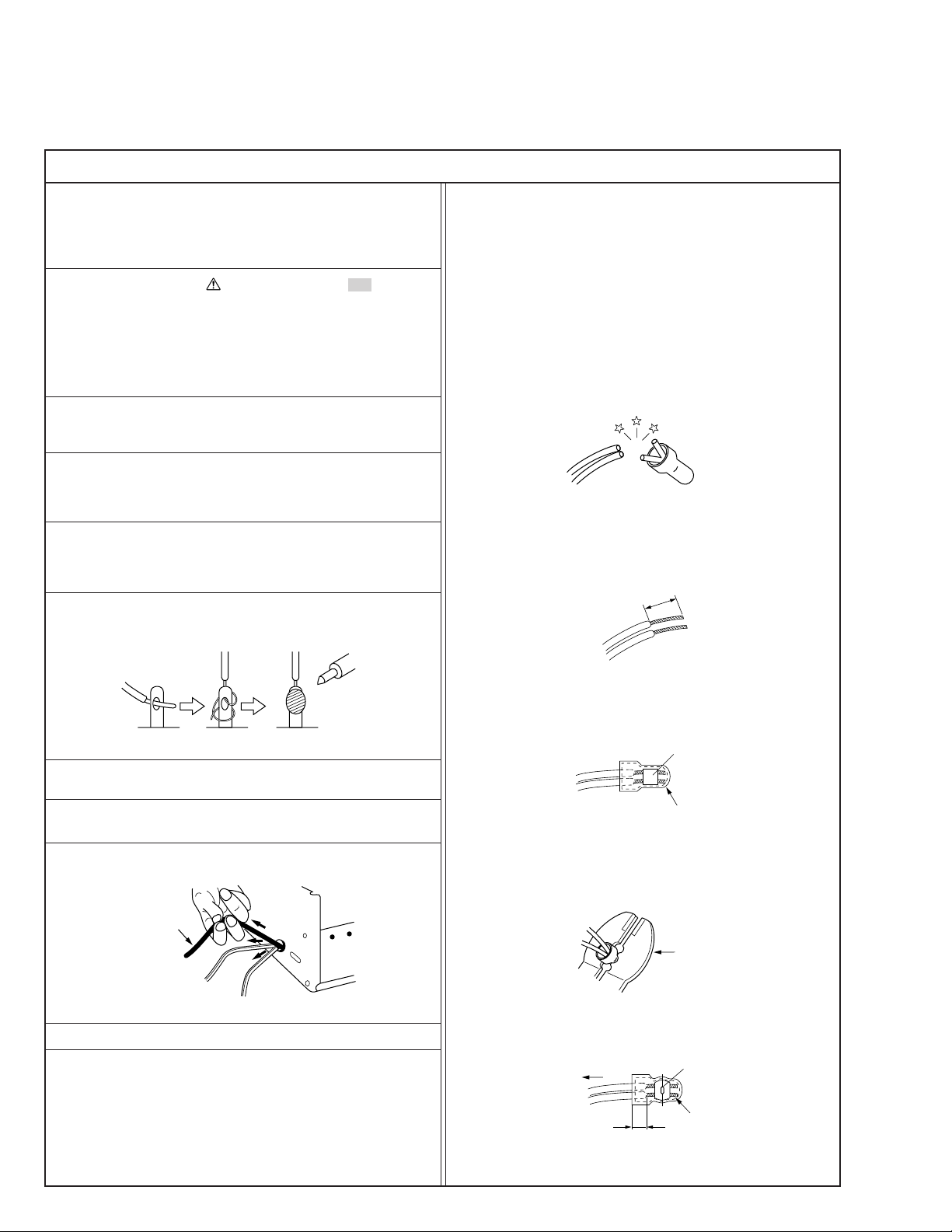
12. Crimp type wire connector
In such cases as when replacing the power transformer in sets
where the connections between the power cord and power
transformer primary lead wires are performed using crimp type
connectors, if replacing the connectors is unavoidable, in order to prevent safety hazards, perform carefully and precisely
according to the following steps.
1) Connector part number : E03830-001
2) Required tool : Connector crimping tool of the proper type
which will not damage insulated parts.
3) Replacement procedure
(1) Remove the old connector by cutting the wires at a point
close to the connector.
Important : Do not reuse a connector (discard it).
cut close to connector
Fig.3
(2) Strip about 15 mm of the insulation from the ends of
the wires. If the wires are stranded, twist the strands to
avoid frayed conductors.
15 mm
Fig.1
7. Observe that wires do not contact heat producing parts
(heatsinks, oxide metal film resistors, fusible resistors, etc.)
8. Check that replaced wires do not contact sharp edged or
pointed parts.
9. When a power cord has been replaced, check that 10-15 kg of
force in any direction will not loosen it.
Power cord
Fig.2
10. Also check areas surrounding repaired locations.
11. Products using cathode ray tubes (CRTs)
In regard to such products, the cathode ray tubes themselves,
the high voltage circuits, and related circuits are specified for
compliance with recognized codes pertaining to X-ray emission.
Consequently, when servicing these products, replace the cathode ray tubes and other parts with only the specified parts.
Under no circumstances attempt to modify these circuits.
Unauthorized modification can increase the high voltage value
and cause X-ray emission from the cathode ray tube.
Fig.4
(3) Align the lengths of the wires to be connected. Insert
the wires fully into the connector.
Fig.5
(4) As shown in Fig.6, use the crimping tool to crimp the
metal sleeve at the center position. Be sure to crimp fully
to the complete closure of the tool.
1.25
2.0
5.5
Fig.6
(5) Check the four points noted in Fig.7.
Not easily pulled free
Wire insulation recessed
more than 4 mm
Fig.7
Crimping tool
Crimped at approx. center
of metal sleeve
Conductors extended
1
S40888-01
Page 4
v
Safety Check after Servicing
Examine the area surrounding the repaired location for damage or deterioration. Observe that screws, parts and wires have been
returned to original positions, Afterwards, perform the following tests and confirm the specified values in order to verify compliance with safety standards.
1. Insulation resistance test
Confirm the specified insulation resistance or greater between power cord plug prongs and
externally exposed parts of the set (RF terminals, antenna terminals, video and audio input
and output terminals, microphone jacks, earphone jacks, etc.). See table 1 below.
2. Dielectric strength test
Confirm specified dielectric strength or greater between power cord plug prongs and exposed
accessible parts of the set (RF terminals, antenna terminals, video and audio input and output
terminals, microphone jacks, earphone jacks, etc.). See table 1 below.
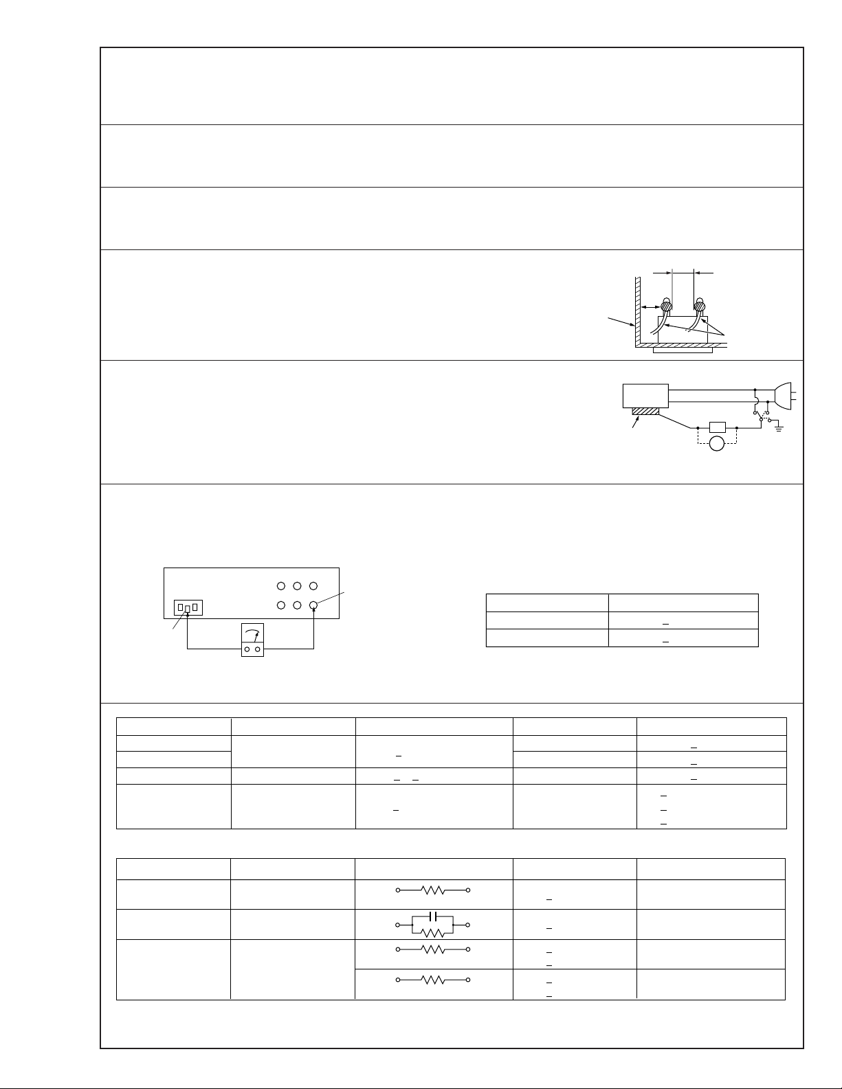
3. Clearance distance
When replacing primary circuit components, confirm specified clearance distance (d), (d’) between soldered terminals, and between terminals and surrounding metallic parts. See table 1
below.
Chassis
Fig. 8
4. Leakage current test
Confirm specified or lower leakage current between earth ground/power cord plug prongs
and externally exposed accessible parts (RF terminals, antenna terminals, video and audio
input and output terminals, microphone jacks, earphone jacks, etc.).
Measuring Method : (Power ON)
Insert load Z between earth ground/power cord plug prongs and externally exposed accessible parts. Use an AC voltmeter to measure across both terminals of load Z. See figure 9 and
following table 2.
5. Grounding (Class 1 model only)
Confirm specified or lower grounding impedance between earth pin in AC inlet and externally exposed accessible parts (Video in,
Video out, Audio in, Audio out or Fixing screw etc.).
Measuring Method:
Connect milli ohm meter between earth pin in AC inlet and exposed accessible parts. See figure 10 and grounding specifications.
AC inlet
Earth pin
Exposed accessible part
Grounding Specifications
Region
USA & Canada
Europe & Australia
Externally
exposed
accessible part
Grounding Impedance (Z)
d
d'
≤
Z 0.1 ohm
≤
Z 0.5 ohm
Power cord,
primary wire
Z
V
Fig. 9
ab
c
Milli ohm meter
Fig. 10
AC Line Voltage
100 V
100 to 240 V
110 to 130 V
110 to 130 V
200 to 240 V
100 V
110 to 130 V
110 to 130 V
220 to 240 V
Note: These tables are unofficial and for reference only. Be sure to confirm the precise values for your particular country and locality.
Region
Japan
USA & Canada
Europe & Australia R 10 MΩ/500 V DC
Region Load Z
Japan
USA & Canada
Europe & Australia
Table 2 Leakage current specifications for each region
Insulation Resistance (R)
≤
R 1 MΩ/500 V DC
≥≥
1 MΩ R 12 MΩ/500 V DC
≤
Table 1 Specifications for each region
1 kΩ
0.15 µF
1.5 kΩ
2 kΩ
50 kΩ
Dielectric Strength
AC 1 kV 1 minute
AC 1.5 kV 1 miute
AC 1 kV 1 minute
AC 3 kV 1 minute
AC 1.5 kV 1 minute
i 1 mA rms Exposed accessible parts
i 0.5 mA rms
i 0.7 mA peak
i 2 mA dc
i 0.7 mA peak
i 2 mA dc
2
≤
≤
≤
≤
≤
≤
(Class 2)
(Class 1)
Clearance Distance (d), (d')
≤
d, d' 3 mm
≤
d, d' 4 mm
≤
d, d' 3.2 mm
≤
d 4 mm
≤
d' 8 mm (Power cord)
≤
d' 6 mm (Primary wire)
a, b, cLeakage Current (i)AC Line Voltage
Exposed accessible parts
Antenna earth terminals
Other terminals
S40888-01
Page 5

Page 6
SECTION 1
Connector
Wire
DISASSEMBLY
1.1 SERVICE CAUTIONS
1.1.1 Precautions
1. Before disassembling/re-assembling the set as well as
soldering parts, make sure to disconnect the power
cable.
2. When disconnecting/connecting connectors, pay enough
attention to wiring not to damage it.
3. In general, chip parts such as resistor, shorting jumpers
(0-ohm resistor), ceramic capacitors, diodes, etc. can not
be reused after they were once removed.
4. When installing parts, be careful not to do with other parts
as well as not to damage others.
5. When removing ICs, be careful not to damage circuit
patterns.
6. Tighten screws properly during the procedures. Unless
specified otherwise, tighten screws at torque of 0.196 N·m
(2.0 kgf·cm).
1.1.2 How to read the disassembly and assembly
(For Cabinet Parts)
STEP
/LOC PART
NO.
Fig.
No.
REMOVAL
*UNLOCK/RELEASE/
UNPLUG/UNCLAMP/
UNSOLDER
1 CASSETTE C1 (S1),3(L1a),(L1b),(L1c)
COVER ASSEMBLY Push button, spring
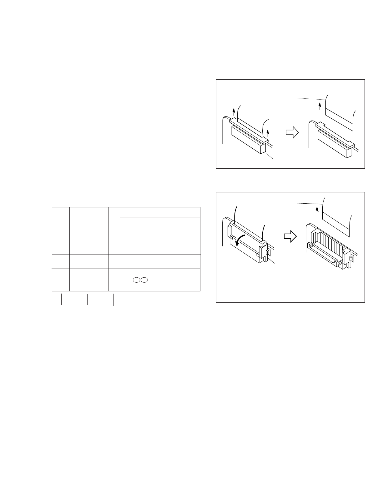
1.1.3 Connection of the wires
1. Pull the connector structure upward to release the clamp
when removing or inserting the flat wire cable.
Fig. 1-1-1
Wire
2
UPPER CASE C2 2(S2), (L2)
LOWER CASE C3 9(S3), (L3a), (L3b)
3 ASSEMBLY(INCL. *CN 3a 3b
E. VF. ASSEMBLY) CAP (RCA jack)
▲
▲
(1) (2) (3) (4)
(1) Order of steps in Procedure
When reassembling, preform the step(s) in the reverse
order. These numbers are also used as the identifica-
tion (location) No. of parts Figures.
(2) Part to be removed or installed.
(3) Fig. No. showing Procedure or Part Location.
C = Cabinet
CA = Camera
D = Deck
(4) Identification of part to be removed, unhooked, unlocked,
released, unplugged, unclamped or unsoldered.
P = Spring
W = Washer
S = Screw
* = Unhook, unlock, release, unplug or unsolder.
2(S3) = 2 Screws (S3)
CN = Connector
(5) Adjustment information for installation.
▲
▲
NOTE:
Connector
After removing the wire, return the stopper to
its original position, because it is apt to come
off if it is left open.
Fig. 1-1-2
1-1
Page 7
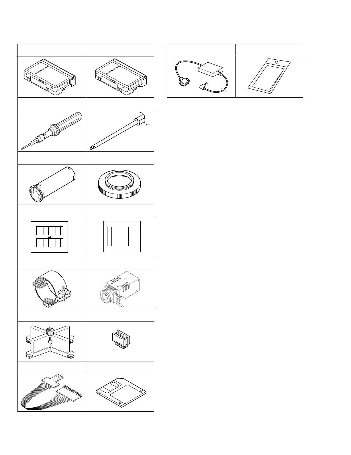
1.2 TOOLS REQUIRED FOR ADJUSTMENTS
Alignment tape
(for SP interchangeability)
1
3
5
78
MHPE-C
Torque driver
YTU94088
INF adjustment lens
YTU92001B
Gray Scale Chart
YTU94133A
Alignment tape
(for N. SP PB Y/C level)
2
4
6
MHVE-2C
YTU94088-003
Conn. ring
YTU92001-111
Color Bar Chart
YTU94133C
Bit
15 16
PC cable
QAM0099-002
Table 1-2-1
Cleaning cloth
KSMM-01
INF lens holder
910
11 12
13
YTU94087
Camera stand
YTU93079
Jig connector cable
YTU93106A
Light box Assembly
YTU93096A
Extension connector
YTU94145B-30
Service support system software
14
YTU94057-51
1-2
Page 8

1,2. Alignment tape
To be used for check and adjustment of interchangeability
of the mechanism.
(Video: Color bar signal, Audio: Non-signal)
3. Torque driver
Be sure to use to fastening the mechanism and exterior
parts because those parts must strictly be controlled for
tightening torque.
4. Bit
This bit is slightly longer than those set in conventional
torque drivers.
5. INF adjustment lens
To be used for adjustment of the camera system.
6. Conn. ring
The connector ring to attach the INF. lens to the head of
the OP lens.
7. Color bar chart
To be used for adjustment of the camera system.
8. Gray scale chart
To be used for adjustment of the camera system.
9. INF lens holder
To be used together with the camera stand (11) for
operating the VideoMovie in the stripped-down condition
such as the status without the exterior parts or for using
commodities that are not yet conformable to the
interchangeable ring.
10. Light box
To be used for adjustment of the camera system.
11. Camera stand
To be used together with the INF adjustment lens holder.
12. Extention connector
To be used to JIG connector cable
13. JIG connector cable
Connected to CN25 of the main board and used for
measuring error rates, etc.
14. Service support software
To be used for adjustment with a personal computer.
15. PC cable
To be used to connect the VideoMovie and a personal
computer with each other when a personal computer is
used for adjustment.
16. Cleaning cloth
Recommended cleaning cloth to wipe down the video
heads, mechanism (tape transport system), optical lens
surface.
1.3 DISASSEMBLY/ASSEMBLY OF CABINET PARTS
1.3.1 Disassembly flow chart
This flowchart indicates the disassembly step for the cabinet parts and board assembly in order to gain access to
item(s) to be serviced. When reassembling, perform the
step(s) in reverse order. Bend, route and dress the flat cables as they were originally.
1 Cassette cover assembly
▼
2 Upper case
▼
3 Lower case assembly
(Incl. E. VF assembly)
▼
4 E. VF assembly
▼
5 Top operation unit
6 Rear unit
▼
▼
7 Front cover assembly
(Incl. Microphone,
DC light assembly)
▼
8 Microphone
9 DC light assembly
▼
▼
▼
0 Upper cover (S) assembly
- Front frame assembly
▼
Note:
For screw management, refer to the table appearing
in the section "3.3 SERVICE NOTE" (page 3-5).
1-3
Page 9

1.3.2 Disassembly method
1
(S1)
(L1c)
1
(L1b)
Spring
(L1a)
Push button
STEP
/LOC PART
NO.
Fig.
No.
REMOVAL
*UNLOCK/RELEASE/
UNPLUG/UNCLAMP/
UNSOLDER
1 CASSETTE C1 (S1),3(L1a), (L1c), (L1b)
COVER ASSEMBLY Push button, spring
2
UPPER CASE C2 2(S2), 2(L2)
3 LOWER CASE C3 9(S3), (L3a), (L3b)
ASSEMBLY (INCL. *CN 3a
E. VF ASSEMBLY) CAP (RCA jack)
4 E. VF ASSEMBLY C4 3(S4)
5 TOP OPERATION C5 2(S5), (L5a), (L5b), (L5c)
UNIT *CN 5a
6 REAR UNIT C6 3(S6), (L6a), (L6b)
*CN 6a
7 FRONT COVER C7 3(S7a), (S7b), (L7a), (L7b)
ASSEMBLY (INCL. MIC *CN 7a
DC LIGHT ASSEMBLY)
8 MICROPHONE (S7a)
DC LIGHT ASSEMBLY 2(L7c)
9
COVER (LIGHT) 2(L7c)
0 UPPER COVER (S) C8 2(S8a), (S8b)
ASSEMBLY
- FRONT FRAME C9 2(S9)
ASSEMBLY
<NOTE 2, 3>
(1) The FPC assembly should be winded around the hinge
assembly by two and half turns so that the wire to be
connected to the monitor board assembly is positioned
inside.
(2) The upper and lower hinge covers should be mounted so
carefully the any wire is not caught into either of the
covers.
List of Abbreviations:
1(S1)=1 screws (S1)
3(L1a)=3 Locking Tabs
CN=Connector
Reference Notes:
<NOTE 1>
Destination of connectors
Two kinds of double-arrows in connection tables
Note:
respectively show kinds of connector/wires.
: Flat wire
: Wire
Con- No. of
nector Pins
3a 5 E. VF (B/W) MAIN CN12
5a 12 TOP OPERATION UNIT MAIN CN18
6a 13 REAR UNIT MAIN CN28
7a 2 MIC
Connector
MAIN CN8
2
(S2)
(L2)
(S2)
Fig. C1
2
3
1-4
Fig. C2
Page 10

7
(S3)
5
(S3)
6
(S3)
8
(S3)
CAP
(RCA jack)
12
(S3)
4
(S3)
(L3b)
9
(S3)
11
(S3)
3a
(L3a)
3
10
(S3)
Fig. C3
(L5c)
13
(S4)
15
(S4)
14
4
(S4)
16
(S5)
17
(S5)
5
(L5a)
(L5b)
Fig. C4
5a
Fig. C5
1-5
Page 11

6a
(L6a)
(L6b)
19
(S6)
18
(S6)
6
20
(S6)
Fig. C6
(L7c)
9
NO.VIDEO
LIGHT MODEL
(L7c)
9
VIDEO LIGHT
USED MODEL
(L7a)
7
8
(L7b)
21
(S7a)
22
(S7a)
24
(S7a)
7a
23
(S7b)
1-6
Fig. C7
Page 12

: 0.098N·m (1.0kgf·cm)
: 0.098N·m (1.0kgf·cm)
29
(S9)
28
(S9)
11
Fig. C8
27
(S8b)
10
25
(S8a)
26
(S8a)
Fig. C9
1-7
Page 13

1.4 DISASSEMBLY/ASSEMBLY OF CAMERA SECTION AND DECK SECTION
1.4.1 Flowchart of disassembly
The following flowchart shows the disassembly of the camera
section and deck section. When assembly of the camera
section and deck section, follow this flowchart in the reverse
order.
<Camera section/Deck section>
1
Zoom unit assembly
▼
2 Main board assembly
3 OP block assembly
▼
(Incl. CCD board assembly)
▼
3 OP block assembly
3
CCD board assembly
For details of disassembly of
manner, refer to page 1-12,
“1.5 REPLACEMENT OF
CCD IMAGE SENSOR.
▼
▼
4 Frame assembly
5 Cassette housing assembly
▼
Reference Notes:
<NOTE 1>
Open two pins of the cennter and connect CN4 as shown in
Fig.
<NOTE 2>
Destination of connectors
Two kinds of double-arrows in connection tables re-
Note:
spectively show kinds of connector/wires.
: Flat wire
: Wire
Con- No. of
nector Pins
Connector
1a 14 MAIN CN13 ZOOM UNIT
2a 14 MAIN CN2 SENSOR
2b 11 MAIN CN5 VIDEO/FLY. E HEAD
2c 10 MAIN CN1 DRUM MOTOR
2d 6 MAIN CN4 (PIN 1,2)
MAIN CN4 (PIN 5,6)
LOADING MOTOR
DC LIGHT
(OPEN TWO PINS OF
THE CENTER AND
CONNECT)
2e 22 MAIN CN15 OP BLOCK
2f 18 MAIN CN3 CAPSTAN MOTOR
2g 11 MAIN CN7 A/C HEAD
2h 14 MAIN CN22
CCD
1.4.2 Disassembly method
STEP
/LOC PART
NO.
Fig.
No.
*UNLOCK/RELEASE/
UNPLUG/UNCLAMP/
1 ZOOM UNIT D1 4(S1)
ASSEMBLY *CN 1a
2 MAIN BOARD D2 (S2), (L2a), (L2b)
*CN 2a , 2b , 2c , 2d , 2e
2f , 2g , 2h
3 OP BLOCK D3 2(S3)
ASSEMBLY CUSHION (OP)
4 FRAME ASSEMBLY D4 (S4a), 2(S4b), (S4c)
5 CASSETTE D5 4(S5)
HOUSING
ASSEMBLY
List of Abbreviations:
2(S1) = 2 Screws (S1)
4(L1a)=4 Locking Tabs (L1a)
CN=Connector
REMOVAL
UNSOLDER
1
(S1)
2
(S1)
4
(S1)
1
1a
3
(S1)
Fig. D1
1-8
Page 14

2
c
10
(S4b)
9
(S4b)
11
(S4c)
4
: 0.108N·m (1.1kgf·cm)
: 0.127N·m (1.3kgf·cm)
8
(S4a)
14
(S5)
12
(S5)
15
(S5)
13
(S5)
5
: 0.186N·m (1.9kgf·cm)
2h
(L2a)
2a
3
5
(S2)
2b
2c
2g
2e
2d
White
Fig. D2
2f
Note1
Red
(L2b)
Red
Fig. D4
7
(S3)
Cushion (OP)
Fig. D3
6
(S3)
Fig. D5
1-9
Page 15

1.5 REPLACEMENT OF CCD IMAGE SENSOR Notes:
•
Pay the most careful attention to the transparent glass
and optical LPF of the CCD image sensor so a not the
soil and damage them. If something is soiled with finger-prints, etc., gently clean it with silicon-processed
paper/cloth or chamois.
• When the CCD image sensor is shipped from the fac-
tory, there are protection seals applied onto the transparent glass. Leave the protector as it is, and take it off just
before assembling the CCD image sensor to the OP
block.
1.5.1 Removal of CCD image sensor
1. Remove two screws (1, 2) securing the CCD base assy,
and disassemble the CCD spacer, the optical LPF,
spacer rubber.
1.5.2 Installation of new CCD image sensor
1. Remove the protection seal from a new CCD image sensor. Next, put the optical LPF, spacer rubber, CCD spacer
on the CCD image sensor as they are piled up in this
order. At that time, make sure of orientation of each item
refering to the following table (see Fig. 1-5-1).
Part Name Orientation
CCD image sensor Mark is on the right viewed as indi-
cated by the arrow a .
Spacer rubber IC side is horizontal.
Optical LPF Marks are on the left and bottom
viewed as indicated by the arrow
a .
2. Fix the CCD base assy to OP block with the two screws
(1, 2) . At that time, be careful of the orientation.
3. After completion of all P.C. boards to the camera section, observe the monitor to confirm no vignetting caused
by the bodytube, rings, lens hood, etc. If no vignetting is
observed, it can be said that image's parallel, horizontality
and centering are correct.
1.5.3 Replacement of CCD board assy
1. Remove one screw (3).
2. Unsolder at the fourteen points on the CCD board assy.
1. Remove the screw (3) only when the CCD board
Note:
assy needs replacement.
2. When installing a new CCD board assy, carry out the
above-mentioned procedure in the reverse order.
Optical LPF
Blue
OP
side
CCD
side
(S1a)
CCD base assembly
CCD spacer
Spacer rubber
: 0.118N·m (1.2kgf·cm)
a
3
1
2
(S1a)
(S1b)
CCD board
assembly
1-10
Fig. 1-5-1
Page 16

1.6 TAKE OUT CASSETTE TAPE
In the event that the set enters the emergency mode as it is
loaded with a cassette tape and the cassette tape cannot
be ejected with the EJECT button, manually, take it out of
the set according to the following procedure.
Note:
If the mechanism comes into the unloading mode as
the cassette tape is not held by hand, it results in tape
damage.
1. Disconnect the set from the power source.
2. Remove the cassette cover assembly, Cover (VF), top
cover, (See Fig. C1, C2 and C3, Page 1-1, 2, 3 and 4)
3. Connect a jumper wire to each pole of the loading motor
as shown by the magnified view b (Fig. 1-6-1)
Battery
4. While holding down the cassette housing by hand, connect the jumper wires to a battery to run the mechanism
to the EJECT position four unloading. If this unloading
operation is performed as the cassette housing is not
held down by hand, the front lid of the cassette may
damage the tape when it is ejected.
5. For taking in the slack of the tape, run the mechanism
to the EJECT position as the front lid of the cassette is
left open, and turn the take-up gear in the forward direction to wind up the tape. After confirming that the tape
has completely been wound up and the supply reel is
idling, take the cassette tape out of the cassette housing.
Magnified view
Top view
b
Take-up gear
Fig. 1-6-1
1-11
Page 17

1.7 EMERGENCY DISPLAY
©
R
D
N
E
.
ECXZT
M
O
S
O
O
Y
D
M
SETEM ME
S
5
N
P
0
U
x
©
F
E
M
T
O
X
.
O
C
P
W
U
O
.
S
S
S
B
C
Y
U
.
A
S
R
M
T
E
EERMAMMEE
N
A
A
A
N
U
U
U
U
U
T
T
T
O
O
O
Whenever some abnormal signal is input to the
mechacon CPU, an error number (E01, as an exam-
• In an emergency mode, all operations except
turning on/off the POWER switch are ineffectual.
ple) is displayed in the electronic view finder.
In every error status, such the message as shown below alternately appear over and over.
Example (in case of the error number E01):
@@@@
UNIT IN
E01
SAFEGUARD MODE
E01
REMOVE AND
REATTACH BATTERY
E. VF Symptom Mode when observed Resulting mode
E07 Short circuit of capstan MDA Power ON Power OFF
E06 CAPSTAN FG input absent EDIT Power OFF
E04 DRUM FF input absent DRUM rotation Power OFF
E03 SUPPLY REEL FG input absent REC, PLAY, SEARCH, FF
E02
Mode control motor rotates for more than 10
UNLOADING Power OFF
UNLOADING
[Power OFF
sec without shift to next mode.
E01
Mode control motor rotates for more than 10
LOADING Power OFF
sec without shift to next mode.
E00 Overtime the programming transaction REC, PLAY Power OFF
1.8 DEMONSTRATION MODE
This model has the DEMONSTRATION mode.
1) How to set the DEMONSTRATION mode.
The camera can be entered into the DEMONSTRATION mode by setting on the DISPLA Y screen appearing in the viewfinder.
When entering the camera into the DEMONSTRA TION
mode, pay heed to the following matters.
1. Set the POWER switch to turn on
the "M".
Press the MENU WHEEL once. The
first page of the DISPLAY appears
on the LCD monitor (or in the
MENU Wheel
M
A
F
F
O
Y
A
L
P
Recording Start/Stop Button
viewfinder).
No cassette is set in the camcorder or a cassette is set
in the camcorder but it is protected from recording.
Note 1)
The indications of the DISPLAY page very
depending on the setting.
2) How to cancel the DEMONSTRATION mode.
To cancel the DEMONSTRATION mode, turn the
POWER switch off (“POWER OFF”).
2. Turn the MENU WHEEL in the
direction of the arrow to set the
cursor at “NEXT”.
Press the MENU WHEEL once.
The second page of the DISPLAY
appears on the LCD monitor (or in
the viewfinder).
T
E
N
U
S
S
Y
©
R
A
MMEEN
U
E
A
M
C
T
O
E
O
F
M
I
T
E
C
R
M
I
T
.
N
T
I
C
A
M
L
E
E
T
A
L
T
L
E
I
T
M
I
T
E
/
T
A
D
D
O
M
O
M
E
D
©
N
E
T
U
R
R
F
E
F
O
F
F
R
O
O
F
EFNCH
GM.
N
F
R
E
E
O
F
See to
next page
1-12
Fig. 1-8-1
Display 1
Display 2
Page 18

Refer to Fig. 1-9-2.
While the DEMONSTRATION
mode is activated, a word of
“DEMONSTRATION” is
appearing on the screen
scrolling from right to left.
DENO MODE
OFF
ON
EXIT
©
R
I
T
T
D
J
D
V
©
T
E
N
E
I
A
L
E
I
R
O
C
T
L
T
T
I
M
D
E
.
E
L
E
P
O
E
T
C
T
E
/
O
U
S
A
I
T
M
T
I
M
R
Y
M
M
I
A
L
I
D
O
O
N
S
E
E
M
C
A
M
D
U
T
R
E
R
N
E
N
E
T
E
A
O
G
O
M
.
.
M
MEE
N
O
O
O
F
0
O
S
N
U
F
F
F
R
6
N
E
U
F
F
F
ENACMH
Note 2)
As the “DEMO MODE” is executed, the
camcoder enters the DEMONSTRA TION mode
after the title screen of “TITLE CALL” and
“FUTURE” appear in this order.
<Flow chart>
1. TITLE CALL and FUTURE
2. FOG
3. ND EFFECT
4. FADER/WIPE (BLACK)
5. MOSAIC
6. SHUTTER
7. SLIDE
8. DOOR
9. CORNER
10. WINDOW
11. NEGA/POSI
12. STRETCH
13. MOSAIC
14. SEPIA
15. B/W
16. STROBE
17. CLASSIC
18. VIDEO ECHO
35. PIN UP SNAPSHOP
34. WIDE ANGLE
33. 30 ~ 32 (For DSC MODEL ONLY)
32. D.S.C. 9 FRAME
31. D.S.C. 4 FLAME
30. D.S.C. INDEX
29. NIGHT ALIVE 10X
28. NIGHT ALIVE OFF
27. S-VHS (For S-VHS MODEL ONLY)
26. VHS
25. P. STABILIZER OFF
24. P. STABILIZER OFF
23. P. STABILIZER ON
22. P. STABILIZER OFF
21. WIDE OFF
19. WIDE OFF
3. Turn the MENU WHEEL in the
direction of the arrow to set the
cursor at “DEMO MODE”. Then,
press the MENU WHEEL once.
The third page of the DEMO
MODE appears on the LCD
monitor (or in the viewfinder).
20. WIDE ON
Fig. 1-8-2
4. Turn the MENU WHEEL in the direction of the arrow to set the cursor at
“ON”. Then, press the MENU WHEEL
once.
The fourth page of the DISPLAY
appears on the LCD monitor (or in the
viewfinder).
(“DEMO MODE” is switched “ON” from
“OFF” status.)
Display 4Display 3
5. Press the MENU WHEEL once.
The camcorder automatically
enters the DEMONSTRATION
mode and it repeats demonstration operation.
While the camcorder is performing demonstration, all operations
except turning on/off the POWER
switch are ineffectual.
1-13
Page 19

1.9 SERVICE NOTE
1-14
Page 20

SECTION 2
MECHANISM ADJUSTMENT
YMA0030A-E AND YMA0031A-E is used in this model.
For the MECHANISM ADJUSTMENT , pleasa refer to the MECHANISM ASSEMBLY of the Service Manual
GR-FXM37EG (No.86589).
2.1Required adjustment tools
Alignment tape
MHPE-C
Jig connector cable
YTU93106A
Cassette torque meter
PUJ50431-2
Alignment tape
MHPE-LC
Extension connector
YTU94145B-30
Roller Driver
PTU94002-2
Table 2-1-1
2-1
Page 21

SECTION 3
ELECTRICAL ADJUSTMENT
3.1 ELECTRICAL ADJUSTMENT
3.1.1 PREPARATION
1. Precaution
This model does not contain adjustment controls (VR).
General deck system and camera system adjustment are
not required. However, if MAIN board replacement, please
use original EEPROM on to new board. Then adjustment are
not required. And if parts such as the following need replacement, special computerized adjustment are required (Refer
to sec. 3.1.1-4). Please contact to JVC Service for detaile
information.
• OP block
• EEPROM (IC104 of MAIN board)
In the event of malfunction with electrical circuits, troubleshooting with the aid of proper test instruments most be
done first, and then commence necessary repair, replacement and adjustment, etc.
1. In case of wiring to chip test points for measurement, use
IC clips, etc. to avoid any stress.
2. Since connectors are fragile, carefully handle them in
disconnecting and connecting.
3. Shortcircuit between operation un it and DECK chassis.
2. Required test equipment
1. Color TV monitor.
2. AC power adapter
3. Oscilloscope (dual-trace type, observable 100 MHz or
higher frequency)
* It is recommended to use one observable 300 MHz or
higher frequency.
4. Digital voltmeter
5. Frequency counter (with threshold level adjuster)
6. Personal computer
3. Required adjustment tools
For detsails of special jigs necessary for adjustment, refer to
page 1-2 and 1-3 of the Section 1.
4. Setup for E. VF section adjustment
Referring to “SEC. 1 DISASSEMBLY” and connect the E.VF
WIRE to CN12 of the MAIN board.
(LY20686)
Bottom case assy
Parts No.
LY20686
Adjustment ltem : 3.3
Note:
This adjustmentalls into a special adjustment that requires
•
a personal computer.
For details, refer to “3.1.1 Preparation”.
Serial No.
label
Screw
5. Connection for Service support system
Fig. 3-1-1 Connection for Service support system
3-1
Service Support
System software
RS232C
COM Port
MENU
PC CABLE
Personal Computer
Page 22

7 FUSE LOCATION FOR MAIN BOARD ASSEMBLY
60
61
41
IC1601
80
120
17
IC2001
IC2401
4
85
IC4251
1
85
14
38 20
IC4501
119
IC105
9
8
16
1
IC107
5
4
8
1
24
13
FOIL SIDE
14
IC7005
CN12
14
8
5
F6002
F6003
0 1 MAIN PWB
YB10310-01-01
5
4
8
1
IC7006
CN28
113
13
24
2536
IC5202
40
21
157
148
37
IC5201
48
112
2536
112
37
48
24
13
105156
104
2536
37
IC7001
48
1
12
IC4001
208
152
43
IC106
IC104
1
5
8
4
4
2
3
1
56
53
2942
28
IC3501
15
114
0 1 MAIN PWB
YB10310-01-01
CN16
25
36
95
17
IC6001
32
33
F6001
Fig. 3-1-2 FUSE location for MAIN board assembly (FOIL SIDE)
COMPONENT SIDE
232
13
24
12
IC7002
1
37
48
IC4702
14
116
64
49
48
16
1
CN25
30
15
114
CN2
1
IC7009
85
CN11
20
1
8
14
110
CN13
114
IC3003
3
4
5
109
1
73
1
72
IC7008
9
16
146
IC3001
1
19
37
36
1
5
3
4
IC3002
IC102
1
5
3
4
111
39
1
1
44
12
CN19
176
CN18
IC4002
45
CN22
1
38
20
38
2
IC101
1
CN1CN5
114
CN7
1
11
IC4003
20 11
110
133
132
89
88
10
CN3
18 1
IC4202
IC4201
85
17
148
4
1
22
CN15
1
CN4
16
Fig. 3-1-3 FUSE location for MAIN board assembly (COMPONENT SIDE)
3-2
Page 23

3.2 ELECTRONIC VIEWFINDER (E. VF) ADJUSTMENT
Notes:
Unless otherwise specified, all measurement points
and adjustment parts are located on E. VF board.
CRT
CENTERING
MAGNET
FOCUS
MAGNET
F.B.T
Fig. 3-2-1 E. VF
CRT-CN
50E. VF PWB ASSY
VR4
BRIGHT
VR1
V. SIZE
VR2
H. HOLD
CN2
CN1
(a)
Fig. 3-2-3 Horizontal sync. 1
(b)
Fig. 3-2-4 Horizontal sync. 2
3.2.2 PLL adjustment
Subject • Camera picture
Fig. 3-2-2 E. VF board
3.2.1 Horizontal sync.
Subject • Alignment tape
• Stairstep
Mode • PB
Equipment • E. VF
Measurement point • E. VF screen
Adjusting part • VR2 (H. HOLD)
Specification • The midpoint of the two
markings
1) Observing the viewfinder screen, turn VR2 fully clockwise
to make the picture unstable.
2) Slowly return VR2 counterclockwise to find a point where
the picture becomes stable, and mark this position.
3) Turn VR2 fully counterclockwise to make the picture
unstable in the same manner as 1) above.
4) Slowly return VR2 clockwise until the picture becomes
stable, and mark this position.
5) Finally set VR2 to the midpoint between the two markings
of 2) and 4).
Mode • EE
Equipment • E. VF
Measurement point • E. VF screen
Adjusting part •VR1 (V. SIZE)
Specification • Normal picture amplitude
1) Observing the viewfinder screen, adjust VR1 for normal
picture amplitude.
3.2.3 Centering
Subject • Alignment tape
•Stairstep
Mode • PB
Equipment • E. VF
Measurement point • E. VF screen
Adjusting part •Centering magnet (CRT assy)
Specification • The center of the E. VF screen
1) While observing the viewfinder screen, adjust the centering
magnet to locate the stairstep in the center of the viewfinder screen.
3-3
Page 24

3.2.4 Focus
Subject • Camera picture
Mode •EE
Equipment • E. VF
Measurment point •E. VF screen
Adjustment part • Focus magnet (CRT assy)
Specification •
1) While observing the viewfinder screen, adjust the focus
magnet for the deflecting yoke so that the picture at the
central area of the screen is clear and defined.
3.2.5 Brightness
Subject • -
Mode •EE
Equipment • E. VF
Measurment point •E. VF screen
Adjustment part •VR4 (BRIGHT)
Specification •
1) Close the lens with the cap and adjust VR4 so that the
raster of the CRT is just visible in the E. VF.
The center area is clear and defined
•Lens closed
The CRT raster is just barely visible
3-4
Page 25

Page 26

VICTOR COMPANY OF JAPAN, LIMITED
VIDEO DIVISION
S40894
Printed in Japan
 Loading...