

Page 1
DIGITAL VIDEO CAMERA
GR-DVX70
Please visit our CyberCam Homepage on the
World Wide Web and answer our Consumer
Survey (in English only):
http://www.jvc-victor.co.jp/english/index-e.html
ENGLISH
INSTRUCTIONS
LYT0412-001A
EN
Page 2
2 EN
Dear Customer,
Thank you for purchasing this digital video camera. Before use, please read the safety information and
precautions contained in the following pages to ensure safe use of this product.
Using This Instruction Manual
•All major sections and subsections are listed in the Table Of Contents (Z pg. 6, 7).
•Notes appear after most subsections. Be sure to read these as well.
•Basic and advanced features/operation are separated for easier reference.
It is recommended that you . . .
.... refer to the Index (Z pgs. 99 – 106) and familiarize yourself with button locations, etc. before use.
.... read thoroughly the Safety Precautions. They contain extremely important information regarding the safe
use of this product.
You are recommended to carefully read the cautions on pages 107 and 108 before use.
SAFETY PRECAUTIONS
WARNING:
TO PREVENT FIRE OR SHOCK
HAZARD, DO NOT EXPOSE
THIS UNIT TO RAIN OR
MOISTURE.
Warning on lithium cell battery
(for remote control unit)
The battery used in this device may present a fire
or chemical burn hazard if mistreated. Do not
recharge, disassemble, heat above 100°C or
incinerate.
Replace the battery with Maxell, Panasonic
(Matsushita Electric), Sanyo or Sony CR2025; use
of another battery may present a risk of fire or
explosion.
n Dispose of used battery promptly.
n Keep away from children.
n Do not disassemble and do not dispose of in
fire.
NOTES:
●
The rating plate (serial number plate) and safety
caution are on the bottom and/or the back of
the main unit.
●
The rating plate (serial number plate) of the AC
Power Adapter/Charger is on its bottom.
●
The rating plate (serial number plate) of the
Docking Station is on its bottom.
CAUTIONS:
n If you notice smoke or a peculiar smell coming
from the camcorder or AC adapter/charger,
shut it down and unplug it immediately.
Continue using the camcorder or AC adapter/
charger under these conditions could lead to
fire or electric shock. Contact your JVC dealer.
Do not attempt to repair the malfunction
yourself.
n To prevent shock, do not open the cabinet. No
user serviceable parts inside. Refer servicing to
qualified personnel.
n When you are not using the AC Power
Adapter/Charger for a long period of time, it is
recommended that you disconnect the power
cord from AC outlet.
This camcorder is designed to be used with PALtype colour television signals. It cannot be used
for playback with a television of a different
standard. However, live recording and LCD
monitor/ viewfinder playback are possible
anywhere. Use the BN-V507U/V514U battery
packs and, to recharge them, the provided multivoltage AC Power Adapter/Charger. (An
appropriate conversion adapter may be
necessary to accommodate different designs of
AC outlets in different countries.)
This unit is produced to comply with Standard
IEC Publ. 65.
Page 3

EN3
SAFETY PRECAUTIONS
Do not point the lens or the viewfinder directly into the sun. This can cause eye injuries, as well as
lead to the malfunctioning of internal circuitry. There is also a risk of fire or electric shock.
CAUTION!
The following notes concern possible physical damage to the camcorder and to the user.
When carrying, be sure to always attach and use the provided hand strap. Hold the camcorder
firmly in your hand, with the strap securely around your wrist. Carrying or holding the
camcorder by the viewfinder and/or the LCD monitor can result in dropping the unit, or in a
malfunction.
Take care not to get your finger caught in the cassette cover. Do not let children operate the
camcorder, as they are particularly susceptible to this type of injury.
Do not use a tripod on unsteady or unlevel surfaces. It could tip over, causing serious damage to
the camcorder.
CAUTION!
Attaching the camcorder to the Docking Station with cables (Audio/Video, S-Video, Editing, DC,
etc.) connected, then leaving it on top of the TV is not recommended, as tripping on the cables will
cause the camcorder to fall, resulting in damage.
n This camcorder is designed exclusively for the digital video cassette and MultiMediaCard. Only
cassettes marked “
” and memory cards marked “ ” can be used with this unit.
Before recording an important scene . . .
.... make sure you only use cassettes with the Mini DV mark .
.... make sure you only use memory cards with the mark
.... remember that this camcorder is not compatible with other digital video formats.
.... remember that this camcorder is intended for private consumer use only. Any commercial use
without proper permission is prohibited. (Even if you record an event such as a show, performance or exhibition for personal enjoyment, it is strongly recommended that you obtain permission beforehand.)
.
Page 4
4 EN
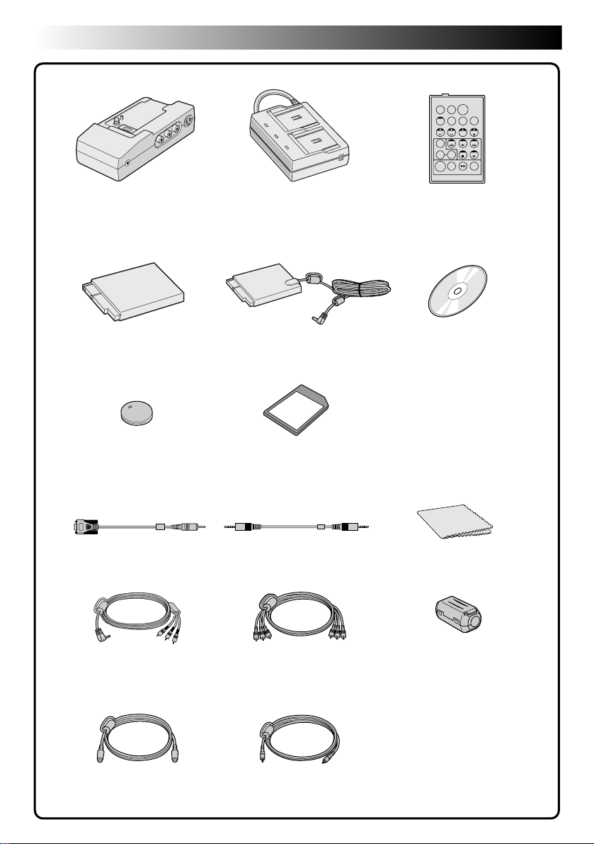
PROVIDED ACCESSORIES
TW
•Docking Station CU-V501E •AC Power Adapter/Charger
•Battery Pack BN-V507U •DC Cord •CD-ROM
•Lithium Battery CR2025
(for remote control unit)
AA-V50A or AA-V50SH
•MultiMediaCard
•JLIP Cable
•Remote Control Unit
The CD ROM contains the
following 7 software
programmes:
• JLIP Video Capture
• JLIP Video Producer
• Picture Navigator (for Windows
• Picture Navigator (for Macintosh
Presto!
• Mr. Photo
• PhotoAlbum
• ImageFolio
RM-V713U
•Cleaning Cloth•PC Connection Cable
®
)
®
)
•Audio/Video (A/V) Cable
[mini-plug to RCA plug]
•S-Video Cable
•Audio/Video (A/V) Cable
[RCA plug to RCA plug]
•Editing Cable
•Core Filter x 3 (for optional
DV cable, headphones and
microphone)
Page 5
ABOUT DV
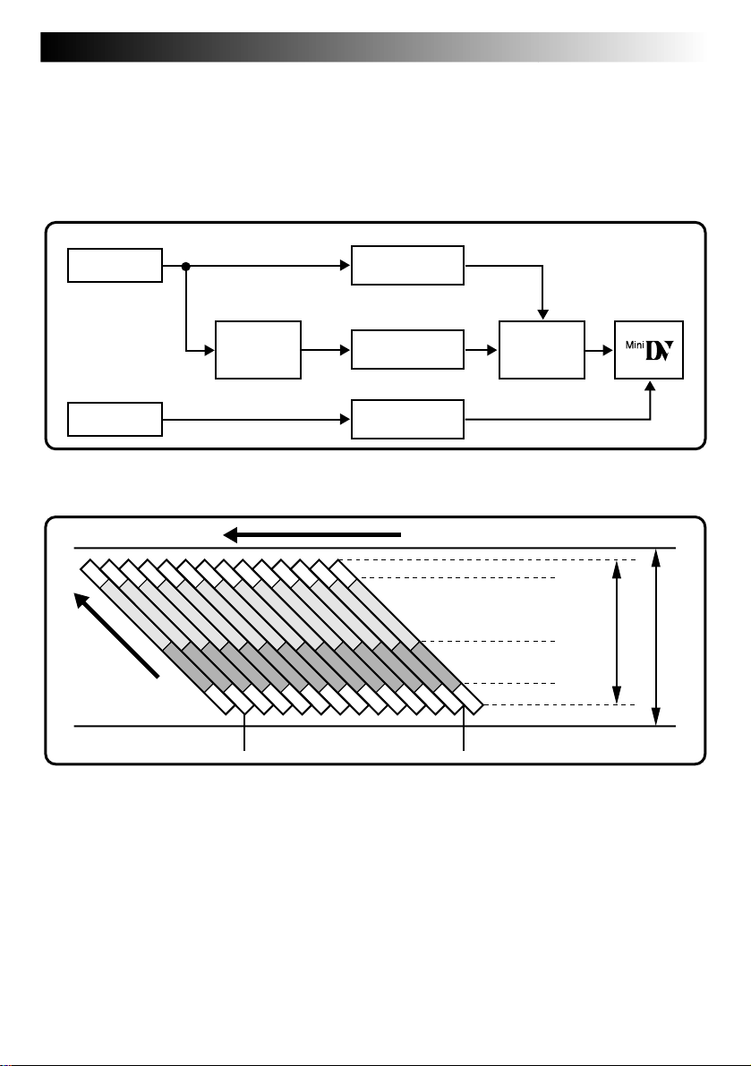
The digital camcorder converts incoming audio and video signals into digital form for recording.
A video signal is composed of a luminance signal (Y) and colour signals (R-Y and B-Y). These signals are
identified and recorded digitally (Digital Component Recording). The A/D (Analogue to Digital) converter
samples the Y signal at 13.5 MHz, and R-Y and B-Y at 6.75 MHz, and changes them to an 8-bit quantum
signal.
Sound sampled at 48 kHz is changed to a 16-bit quantum signal, and sound sampled at 32 kHz is converted to
a 12-bit signal.
EN5
VIDEO
Lens
Chrominance (C)
AUDIO
Mic
This camcorder separates the data into blocks, writing one block of each data type on each track of the tape.
Head tracking
direction
Luminance Signal (Y)
Colour Difference
Signal (R-Y/B-Y)
Chromatic
Analysis
conversion
conversion
conversion
12 tracks/frame
A/D
A/D
A/D
Tape direction
Sub-Code Area
Video Area
Signal
compression
Audio Area
ITI Area
Recording by
rotating head
helical scan
5.24 mm
6.35 mm
1 Sub-Code Area
The Time Code and Date/Time data are
written here, separate from the video data.
This enables you to display the date and
time during playback, even if they weren’t
displayed while recording.
2 Video Area
The digital video signal is recorded here.
3 Audio Area
The digital audio signal is recorded here.
4 ITI (Insert and Tracking
Information) Area
Insert editing and post-recording editing
tracking signals are recorded here.
Page 6

6 EN
CONTENTS
PROVIDED ACCESSORIES
ABOUT DV
GETTING STARTED
Power............................................................................................................ 8
Grip Adjustment ..............................................................................................10
Viewfinder Adjustment ..................................................................................... 10
Date/Time Settings.......................................................................................... 11
Loading/Unloading A Cassette............................................................................. 12
Recording Mode Setting..................................................................................... 13
Loading A MultiMediaCard ................................................................................. 14
Unloading A MultiMediaCard ............................................................................... 14
Picture Quality Mode Setting .............................................................................. 15
Tripod Mounting .............................................................................................. 16
Operation Mode .............................................................................................. 17
RECORDING
Basic Recording For Video .................................................................................. 18
Basic Recording For Digital Still Camera (D.S.C.)........................................................ 22
Basic Recording For Video And D.S.C...................................................................... 24
Advanced Features For Video And D.S.C.................................................................. 26
8 – 17
18 – 51
4
5
PLAYBACK
Basic Playback For Video ................................................................................... 52
Advanced Features For Video .............................................................................. 54
Basic Playback For D.S.C. ................................................................................... 56
Advanced Features For D.S.C. .............................................................................. 57
Advanced Features For Video And D.S.C.................................................................. 68
Basic Connections ............................................................................................ 70
Advanced Connections .......................................................................................72
52 – 73
Page 7

EN7
DUBBING
Dubbing Images/Sounds Recorded On A Tape To Another Tape ....................................... 74
Digital Dubbing Of Recorded Images/Sounds Between Tapes ........................................ 75
Dubbing Images Stored In A MultiMediaCard To A Tape ............................................... 76
Dubbing Images Recorded On A Tape To A MultiMediaCard ........................................... 77
Copying Images Using Infrared Communication [IrTran-P]............................................. 78
USING THE REMOTE CONTROL UNIT
Random Assemble Editing .................................................................................. 84
For More Accurate Editing .................................................................................. 88
Audio Dubbing ................................................................................................ 90
74 – 79
80 – 90
ADDITIONAL INFORMATION
Initializing A MultiMediaCard .............................................................................. 91
TROUBLESHOOTING
92 – 97
USER MAINTENANCE
INDEX
Docking Station............................................................................................... 99
Controls, Connectors And Indicators .................................................................... 100
Indications................................................................................................... 102
Term s ........................................................................................................ 106
99 – 106
91
98
CAUTIONS
SPECIFICATIONS
107 – 108
109 – 110
Page 8
8 EN
Power
This camcorder’s 2-way power supply system lets
you choose the most appropriate source of power.
NOTES:
●
No function is available without power supply.
●
Use only specified power supply.
●
Do not use provided power supply units with other
equipment.
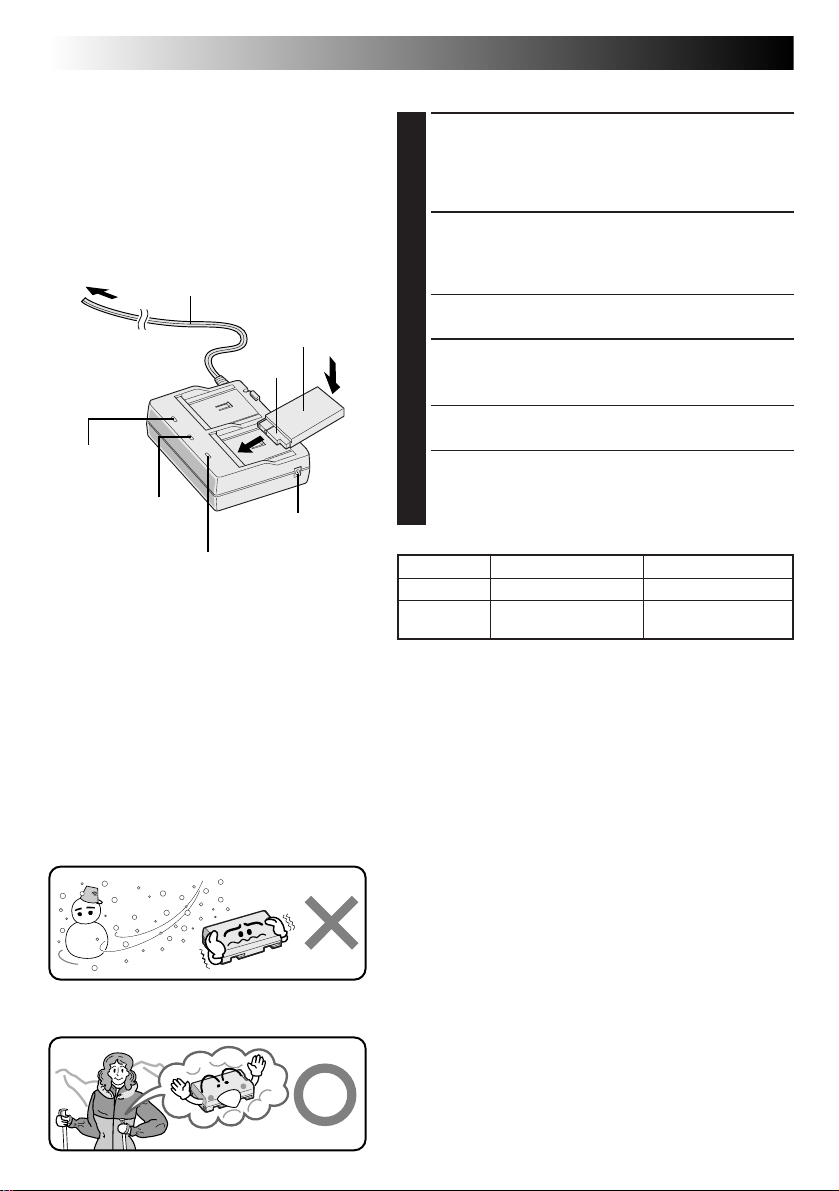
To AC outlet
AC Power
Adapter/Charger
AA-V50A or
AA-V50SH
Charger
indicator 1
Power cord
Power lamp
Charger indicator 2
Battery pack
BN-V507U or
BN-V514U
1
DC OUT terminal
CHARGING THE BATTERY PACK
SUPPLY POWER TO CHARGER
1
Make sure you unplug the camcorder’s DC cord from the
AC Power Adapter/Charger.
Plug the AC Adapter/Charger’s power cord into an AC
outlet. The power lamp comes on.
ATTACH BATTERY/BATTERIES
2
Attach the battery pack while making sure its terminal
side 1 is in contact with the indicator side of the battery
pack mount on the AC Power Adapter/Charger.
• The Charger Indicator (1 or 2) begins blinking to indicate
charging has started.
CONFIRM STATUS
3
When the charger indicator stops blinking but stays lit,
charging is finished.
• If two batteries are attached to the charger, they will be
charged in the order that they were attached.
DETACH BATTERY/BATTERIES
4
Slide the battery or batteries in the opposite direction of
the arrow and lift off. Remember to unplug the AC
Adapter/Charger’s power cord from an AC outlet.
Charging time
Battery pack
BN-V507U approx. 1 hr. 30 min. approx. 3 hrs.
BN-V514U
(optional)
GETTING STARTED
ONE TWO
approx. 3 hrs. approx. 6 hrs.
NOTES:
●
Perform charging where the temperature is between 10° and 30°C. 20° to 25°C is the ideal temperature range for charging.
If the environment is too cold, charging may be incomplete.
●
Charging times noted above are for fully discharged battery pack.
●
Charging time varies according to the ambient temperature and the status of the battery pack.
●
To avoid interference with reception, do not use the AC Power Adapter/Charger near a radio.
●
If you connect the camcorder’s DC cord to the adapter during battery charging, power is supplied to the camcorder and
charging stops.
●
Since the AC Power Adapter/Charger processes electricity internally, it becomes warm during use. Be sure to use it only in
well-ventilated areas.
●
When charging the battery pack for the first time or after a long storage period, the charger indicator may not light. In this
case, remove the battery pack from the AC Power Adapter/Charger, then try charging again.
●
If the battery operation time remains extremely short even after having been fully charged, the battery is worn out and needs
to be replaced. Please purchase a new one.
About Batteries
DANGER! Do not attempt to take the batteries apart, or
expose them to flame or excessive heat, as it may cause a fire
or explosion.
WARNING! Do not allow the battery or its terminals to come
in contact with metals, as this can result in a short circuit and
possibly start a fire.
Lithium-ion is vulnerable in colder
temperatures.
The Benefits Of Lithium-Ion Batteries
Lithium-ion battery packs are small but have a large power
capacity. However, when one is exposed to cold temperatures
(below 10° C), its usage time becomes shorter and it may
cease to function. If this happens, place the battery pack in
your pocket or other warm, protected place for a short time,
then re-attach it to the camcorder. As long as the battery pack
itself is not cold, it should not affect performance.
(If you’re using a heating pad, make sure the battery pack does
not come in direct contact with it.)
Page 9
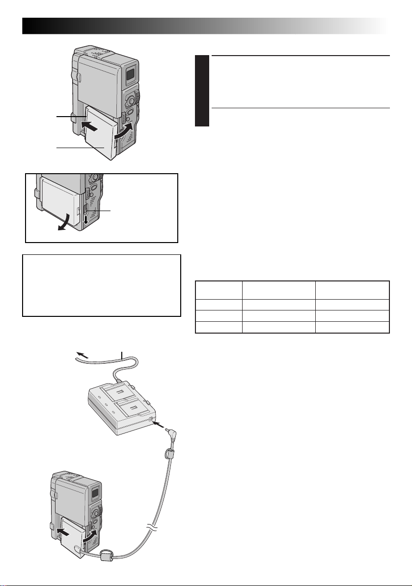
1
2
BATT. RELEASE
Switch
ATTENTION:
Before detaching the power source,
make sure that the camcorder’s power
is turned off. Failure to do so can result
in a camcorder malfunction.
EN9
USING THE BATTERY PACK
ATTACH BATTERY PACK
1
Insert the terminal end 1 of the battery pack into the
battery pack mount, then firmly push the end 2 of
the battery pack in the direction of the arrow until it
locks into place as shown in the illustration.
•
If the battery pack is attached in the wrong position,
a malfunction may occur.
To Detach The Battery Pack . . .
.... while sliding down BATT. RELEASE, detach it.
NOTES:
●
Continuous shooting is possible when the temperature is
approx. 20˚C.
●
However, continuous shooting capability is reduced
significantly under the following conditions:
•
The temperature is below 10˚C.
•
Zoom or Record-Standby mode is engaged repeatedly.
•
The LCD monitor is used repeatedly.
Before extended use, it is recommended that you
prepare enough battery packs to cover 3 times the
planned shooting time.
Approximate recording time
Battery pack
BN-V507U 55 min. 65 min.
BN-V514U 115 min. 130 min.
BN-V856U 7 hrs. 30 min. 8 hrs. 30 min.
LCD monitor on/ LCD monitor off/
Viewfinder off Viewfinder on
To AC outlet
AC Power
Adapter/Charger
AA-V50A or
AA-V50SH
To battery
pack mount
Power cord
To DC OUT
terminal
DC cord
INFORMATION:
VU-V856KIT is a set composed of the BN-V856U battery
pack and AA-V80EG AC Power Adapter/Charger.
Also read thoroughly the VU-V856KIT's instruction
manuals.
It is impossible to charge the BN-V856U battery pack
using the provided AC Power Adapter/Charger. Use the
optional AA-V80EG AC Power Adapter/Charger.
USING AC POWER
Use the AC Power Adapter/Charger (connect as shown in
the illustration).
NOTES:
●
The provided AC Power Adapter/Charger features
automatic voltage selection in the AC range from 110 V
to 240 V.
●
For other notes, Z pg. 8.
Page 10
10 EN
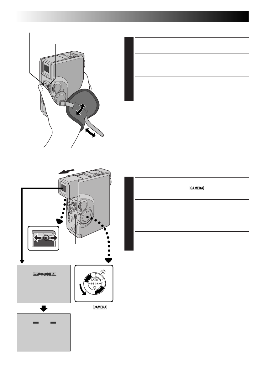
START/STOP Button
GETTING STARTED
Grip Adjustment
(cont.)
Power Zoom Lever
2
3
EXPAND LOOP
1
Separate the Velcro strip.
INSERT HAND
2
Pass your right hand through the loop and grasp the
grip.
ADJUST STRAP LENGTH
3
Adjust so that your thumb and fingers can easily
operate START/STOP and Power Zoom Lever.
Refasten the Velcro strip.
NOTE:
When carrying the camcorder inside a bag, etc., the grip
belt’s metal buckle may damage the camcorder. It is
recommended that you place it inside the Velcro strip.
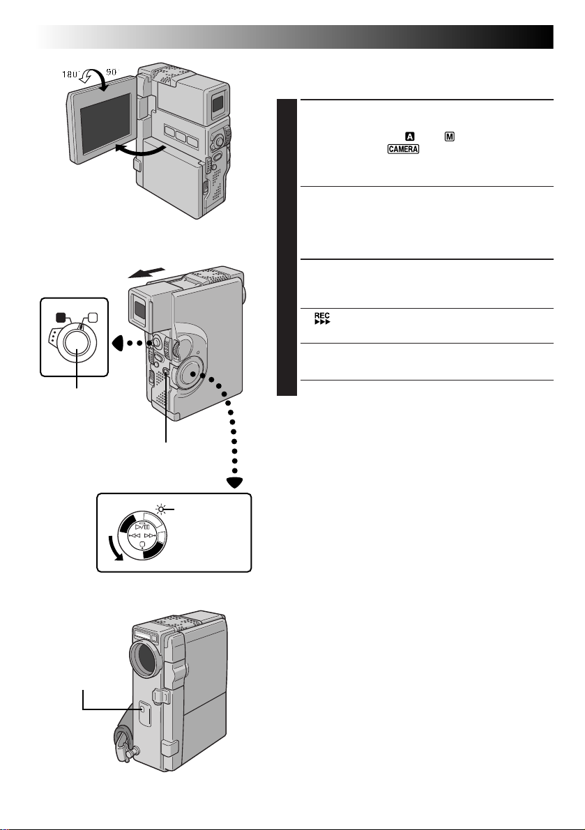
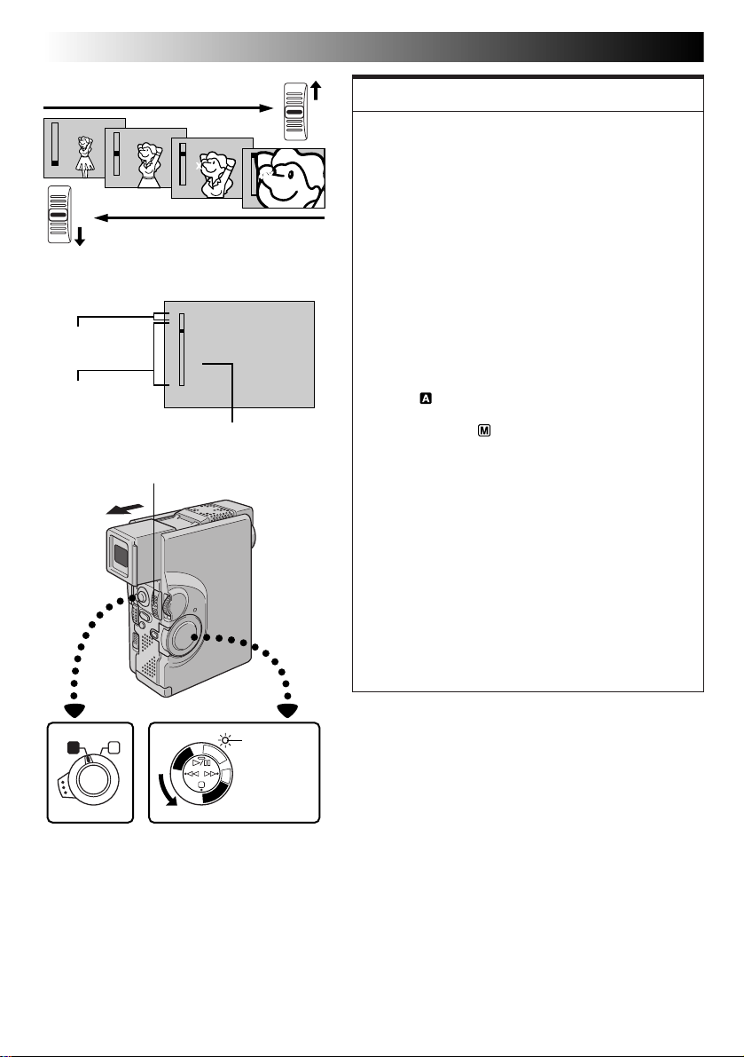
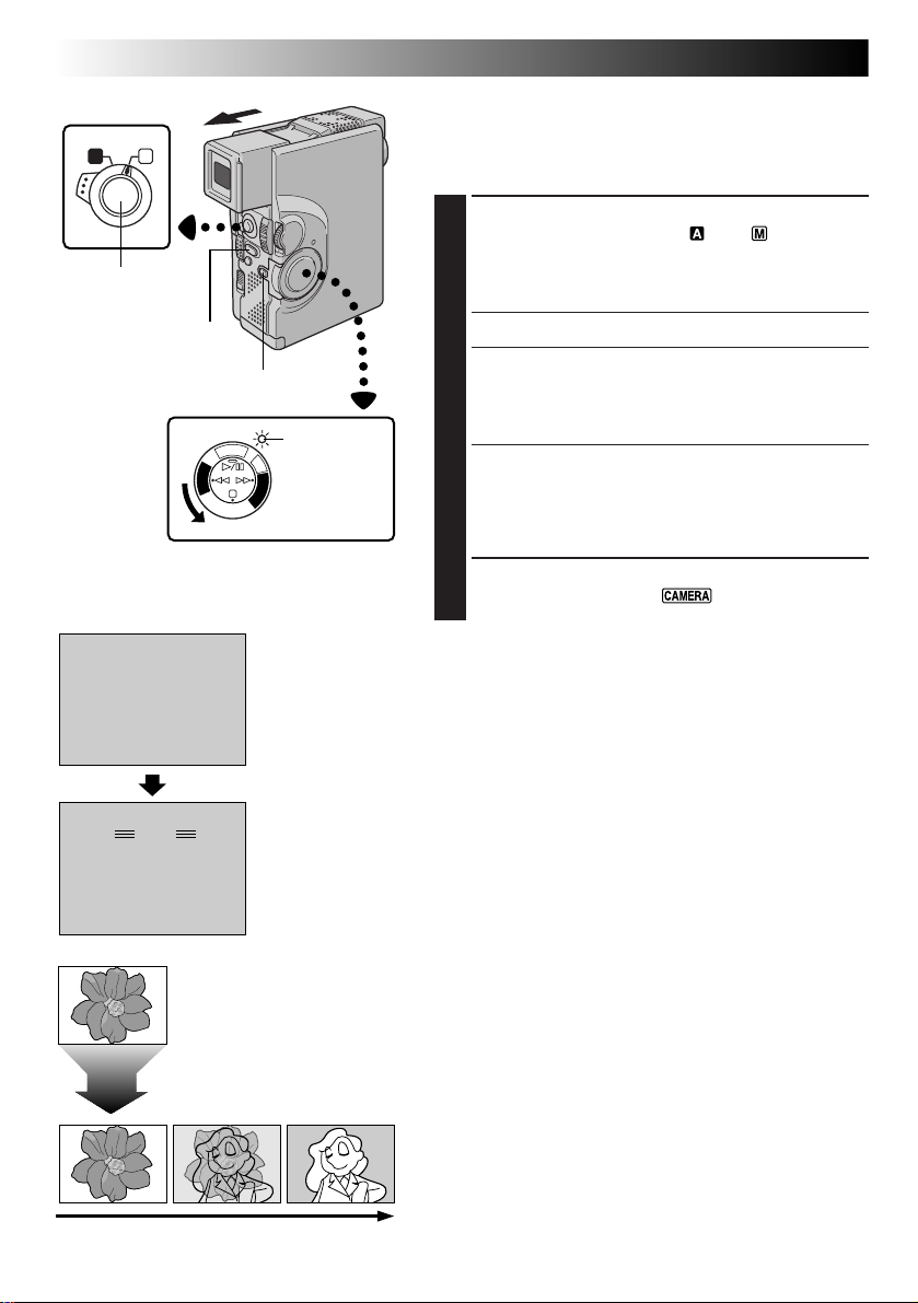
Viewfinder Adjustment
SELECT OPERATION MODE
1
Set the Power Switch to “ ” or “5S” while
pressing down the Lock Button .
POSITION VIEWFINDER
2
Pull out the viewfinder fully.
•The power lamp comes on and the camcorder is
turned on.
PAUSE
Lock Button
1
Set to “
or “5S”.
ADJUST DIOPTRE
3
Slide the Dioptre Adjustment Control until the
indications in the viewfinder are clearly focused.
F
C
F
A
O
M
E
C
R
P
/
A
Y
5
A
S
L
P
D
S
C
D
S
C
P
L
A
Y
”
Page 11
OFF
FLASH ADJ.
P. AE
/ EFFECT
END
0
4
– – – – –6– – – – –
4
TO DATE / TIME MENU
TO SYSTEM MENU
END
OFF
AUTO
FLASH
GAIN UP AGC
SELF-TIMER
Operation Switch
A M
EN11
Date/Time Settings
Date and time will automatically be recorded on tape at
all times. It is your choice to display it or not during
playback (Z pg. 55).
SELECT OPERATION MODE
1
Set the Operation Switch to “ ”. Then, set the
Power Switch to “ ” or “5S” (or “ ”) while
pressing down the Lock Button. Open the LCD
monitor fully or pull out the viewfinder fully.
•The power lamp comes on and the camcorder is
turned on.
Lock Button
Power lamp
F
C
F
A
O
M
E
C
R
P
/
A
Y
5
A
S
L
P
D
S
C
D
S
C
P
L
A
Y
MENU/SET Dial Power Switch
Display
Recording Menu
TO MODE MENU
Mode Menu
DATE/TIME
INDICATION ON
ON SCREEN OFF
4
DATE / TIME
RETURN
ONDISPLAY
1 . 1 . 00
Date/Time Menu
00 : 00
ACCESS RECORDING MENU
2
Press MENU/SET. The Recording Menu appears.
ACCESS MODE MENU
3
Move the highlight bar to “TO MODE MENU” by
rotating MENU/SET. Press it and the Mode Menu
appears.
ACCESS DATE/TIME MENU
4
Move the highlight bar to “TO DATE/TIME MENU”
by rotating MENU/SET. Press it and the Date/Time
Menu appears.
INPUT DATE AND TIME
5
Move the highlight bar to “DATE/TIME” by rotating
MENU/SET. Press it and “day” is highlighted and
begins blinking.
Rotating MENU/SET, input the day. Press it. Repeat the
procedure to input the month, year, hour and minute.
•Press MENU/SET twice when the highlight bar is set
to “RETURN” to exit.
Regarding Built-in Clock’s Rechargeable Lithium Battery
To store the date/time in memory, the clock’s rechargeable
lithium battery is integrated in the camcorder. While the
camcorder is connected to an AC outlet using the AC Power
Adapter/Charger, or while the battery pack attached to the
camcorder continues to supply power to the camcorder, the
clock’s rechargeable lithium battery is always charged.
However, if the camcorder is not used for approx. 3 months,
the clock lithium battery will become discharged and the
date/time stored in memory will be lost. When this occurs,
first connect the camcorder to an AC outlet using the AC
Power Adapter/Charger for over 24 hours to charge the
clock’s rechargeable lithium battery. Then perform the date/
time setting before using the camcorder.
It is also possible to use the camcorder without the date/
time setting.
NOTE:
Even if you select “DATE/TIME”, if the parameter is not highlighted the camcorder's internal clock continues to
operate. Once you move the highlight bar to the first date/time parameter (day), the clock stops. When you
finish setting the minute and press MENU/SET, the date and time begin operation from the date and time you
just set.
Page 12
12 EN
Cassette holder
GETTING STARTED
(cont.)
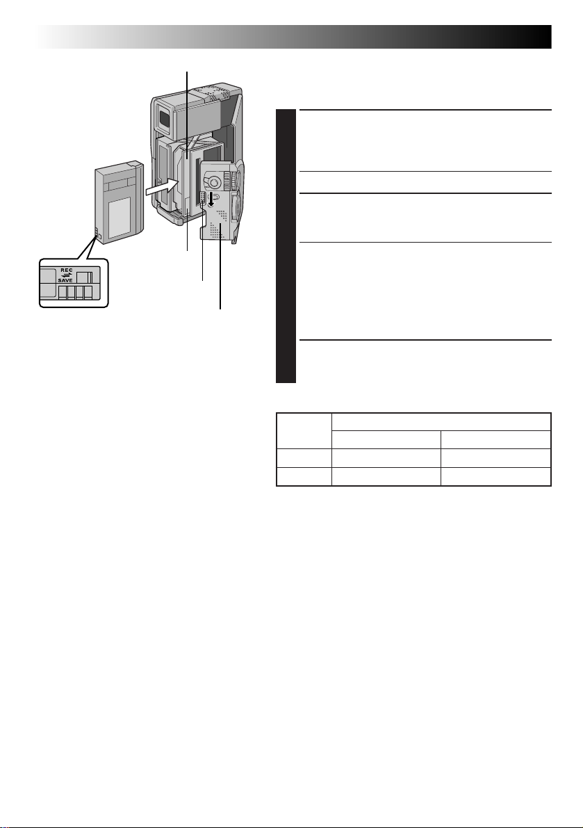
Loading/Unloading A Cassette
The camcorder needs to be powered up to load or eject a
cassette.
Make sure the
window side is
facing out.
PUSH HERE
OPEN/EJECT Switch
Erase protection
switch*
*
To Protect Valuable Recordings . . .
.... slide the erase protection switch on the
back of the tape in the direction of “SAVE”.
This prevents this tape from being recorded
over. If you decide later that you do want
to record on this tape, slide the switch back
to “REC” before loading the tape.
Cassette cover
OPEN CASSETTE COVER
1
Slide OPEN/EJECT in the direction of the arrow then
swing the cover open until it locks. The holder opens
automatically.
•Do not touch internal components.
INSERT/REMOVE TAPE
2
Insert or remove a tape and press “PUSH HERE” to
close the cassette holder.
•Once the cassette holder is closed, it recedes
automatically. Wait until it recedes completely
before closing the cassette cover.
•When the battery’s charge is low, you may not be
able to close the cover. Do not apply force. Replace
the battery with a fully charged one before
continuing.
CLOSE CASSETTE COVER
3
Close the cassette cover firmly until it locks into
place.
Approximate recording time
Tape
DVM-30 30 min. 45 min.
DVM-60 60 min. 90 min.
Recording mode
SP LP
NOTES:
●
It takes a few seconds for the cassette holder to open. Do not apply force.
●
If you wait a few seconds and the cassette holder does not open, close the cassette cover and try again. If the
cassette holder still does not open, turn the camcorder off then on again.
●
If the tape does not load properly, open the cassette cover fully and remove the cassette. A few minutes later,
insert it again.
●
When the camcorder is suddenly moved from a cold place to a warm environment, wait a short time before
opening the cover.
●
Closing the cassette cover before the cassette holder comes out may cause damage to the camcorder.
●
Even when the camcorder is switched off, a cassette can be loaded or unloaded. After the cassette holder is
closed with the camcorder switched off, however, it may not recede. It is recommended to turn the power on
before loading or unloading.
●
When resuming recording, once you open the cassette cover a blank portion will be recorded on the tape or
a previously recorded scene will be erased (recorded over) regardless of whether the cassette holder came
out or not. See page 25 for information about recording from the middle of a tape.
Page 13
Operation Switch
A M
Lock Button
Power lamp
F
C
F
A
O
M
E
C
R
P
/
A
Y
5
A
S
L
P
D
S
C
D
S
C
P
L
A
Y
MENU/SET Dial Power Switch
Display
FOCUS
EXPOSURE AUTO
W. BALANCE
FADER
/ WIPE
P. AE
/ EFFECT
FLASH ADJ.
TO MODE MENU
4
END
4
REC MODE
WIDE MODE OFF
ZOOM
DIS
GAIN UP
SELF-TIMER
FLASH
TO DATE / TIME MENU
TO SYSTEM MENU
END
AUTO
AUTO
OFF
OFF
0
SP
40X
ON
AGC
OFF
AUTO
– – – – –6– – – – –
Recording Menu
Mode Menu
EN13
Recording Mode Setting
Set the tape recording mode according to your preference.
SELECT OPERATION MODE
1
Set the Operation Switch to “ ”. Then, set the Power
Switch to “ ” or “5S” while pressing down the
Lock Button. Open the LCD monitor fully or pull out
the viewfinder fully.
•The power lamp comes on and the camcorder is
turned on.
ACCESS RECORDING MENU
2
Press MENU/SET. The Recording Menu appears.
ACCESS MODE MENU
3
Move the highlight bar to “TO MODE MENU” by
rotating MENU/SET. Press it and the Mode Menu
appears.
SET RECORDING MODE
4
First move the highlight bar to “REC MODE” by
rotating MENU/SET. Press it and the parameter “SP”
or “LP” is highlighted. Select “SP” or “LP” by rotating
MENU/SET. Press it twice to exit from the Recording
Menu.
•Audio Dubbing is impossible on a tape recorded in
the LP mode.
•“LP” (Long Play) is more economical, providing
1.5 times the recording time.
NOTES:
●
If the recording mode is switched during recording, the
playback picture will be blurred at the switching point.
●
It is recommended that tapes recorded in the LP mode
on this camcorder be played back on this camcorder.
●
During playback of a tape recorded on another
camcorder, blocks of noise may appear or there may be
momentary pauses in the sound.
4
REC MODE
WIDE MODE OFF
ZOOM
DIS
GAIN UP
SELF-TIMER
FLASH
TO DATE / TIME MENU
TO SYSTEM MENU
END
SP
40X
ON
AGC
OFF
AUTO
– – – – –6– – – – –
SP
– – – – –6– – – – –
SP LP
Recording mode
indicator
Page 14
14 EN
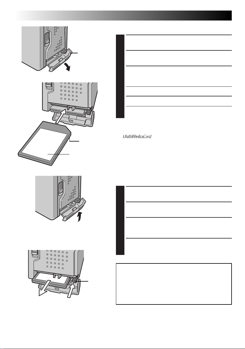
Card Cover
Terminal
MultiMediaCard
GETTING STARTED
(cont.)
Loading A MultiMediaCard
CONFIRM POWER-OFF STATUS
1
Make sure the camcorder’s power is off.
OPEN THE CARD COVER
2
INSERT THE MULTIMEDIACARD
3
Insert the MultiMediaCard terminal end first with the
label facing up (see the illustration on the left).
•Do not touch the terminal.
CLOSE THE CARD COVER
4
•If the card is not installed properly, the card cover
cannot be closed.
NOTES:
●
Be sure to use only MultiMediaCards marked
“ ”.
●
Some brands of MultiMediaCards are not compatible with
this camcorder. Before purchasing a MultiMediaCard,
consult its manufacturer or dealer.
Unloading A MultiMediaCard
The MultiMediaCard retains images in its memory even
after it has been removed from the camcorder.
EJECT
CONFIRM POWER-OFF STATUS
1
Make sure the camcorder’s power is off.
OPEN THE CARD COVER
2
REMOVE THE MULTIMEDIACARD
3
Press EJECT. The MultiMediaCard is disengaged from
the camcorder.
CLOSE THE CARD COVER
4
ATTENTION:
Do not insert/remove the MultiMediaCard while the
camcorder is turned on, as this may cause the
MultiMediaCard to be corrupted or cause the
camcorder to become unable to recognize whether or
not the card is installed.
Page 15
Operation Switch
A M
Lock Button
Power lamp
5
S
A
R
D
E
S
M
C
A
D
C
S
F
C
F
O
P
L
C
A
P
/
Y
Y
A
L
P
MENU/SET Dial Power Switch
Display
FOCUS
EXPOSURE AUTO
W. BALANCE
P. AE
/ EFFECT
FLASH ADJ.
TO MODE MENU
4
END
4
QUALITY
ZOOM
DIS
GAIN UP
SELF-TIMER
FLASH
TO DATE / TIME MENU
TO SYSTEM MENU
END
AUTO
AUTO
OFF
FINE
40X
ON
AGC
OFF
AUTO
– – – – –6– – – – –
0
Recording Menu
Mode Menu
EN15
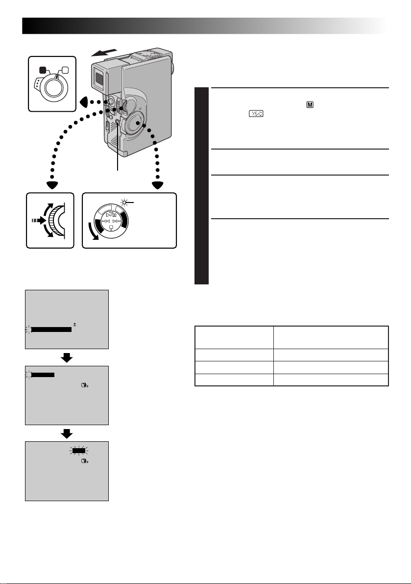
Picture Quality Mode Setting
The Picture Quality mode can be selected to best match
your needs. Three Picture Quality modes are available:
FINE, STANDARD and ECONOMY (in order of quality).
SELECT OPERATION MODE
1
Set the Operation Switch to “ ”. Then, set the Power
Switch to “ ” while pressing down the Lock
Button.
Open the LCD monitor fully or pull out the viewfinder fully.
ACCESS RECORDING MENU
2
Press MENU/SET. The Recording Menu appears.
ACCESS MODE MENU
3
Move the highlight bar to “TO MODE MENU” by
rotating MENU/SET. Press it and the Mode Menu
appears.
SET PICTURE QUALITY MODE
4
First, move the highlight bar to “QUALITY” by
rotating MENU/SET. Press it and the parameter
“FINE”, “STANDARD” or “ECONOMY” is highlighted. Select “FINE”, “STANDARD” or
“ECONOMY” by rotating MENU/SET. Press it twice
to exit the Recording Menu.
NOTE:
The number of storable images depends on the selected
Picture Quality mode as well as the size of the images.
Picture Quality Mode
FINE
STANDARD
ECONOMY
Number of Storable Images
(with provided MultiMediaCard)
Approximately 30
Approximately 50
Approximately 100
4
QUALITY
ZOOM
DIS
GAIN UP
SELF-TIMER
FLASH
TO DATE / TIME MENU
TO SYSTEM MENU
END
FINE
40X
ON
AGC
OFF
AUTO
– – – – –6– – – – –
Page 16
16 EN
GETTING STARTED
(cont.)
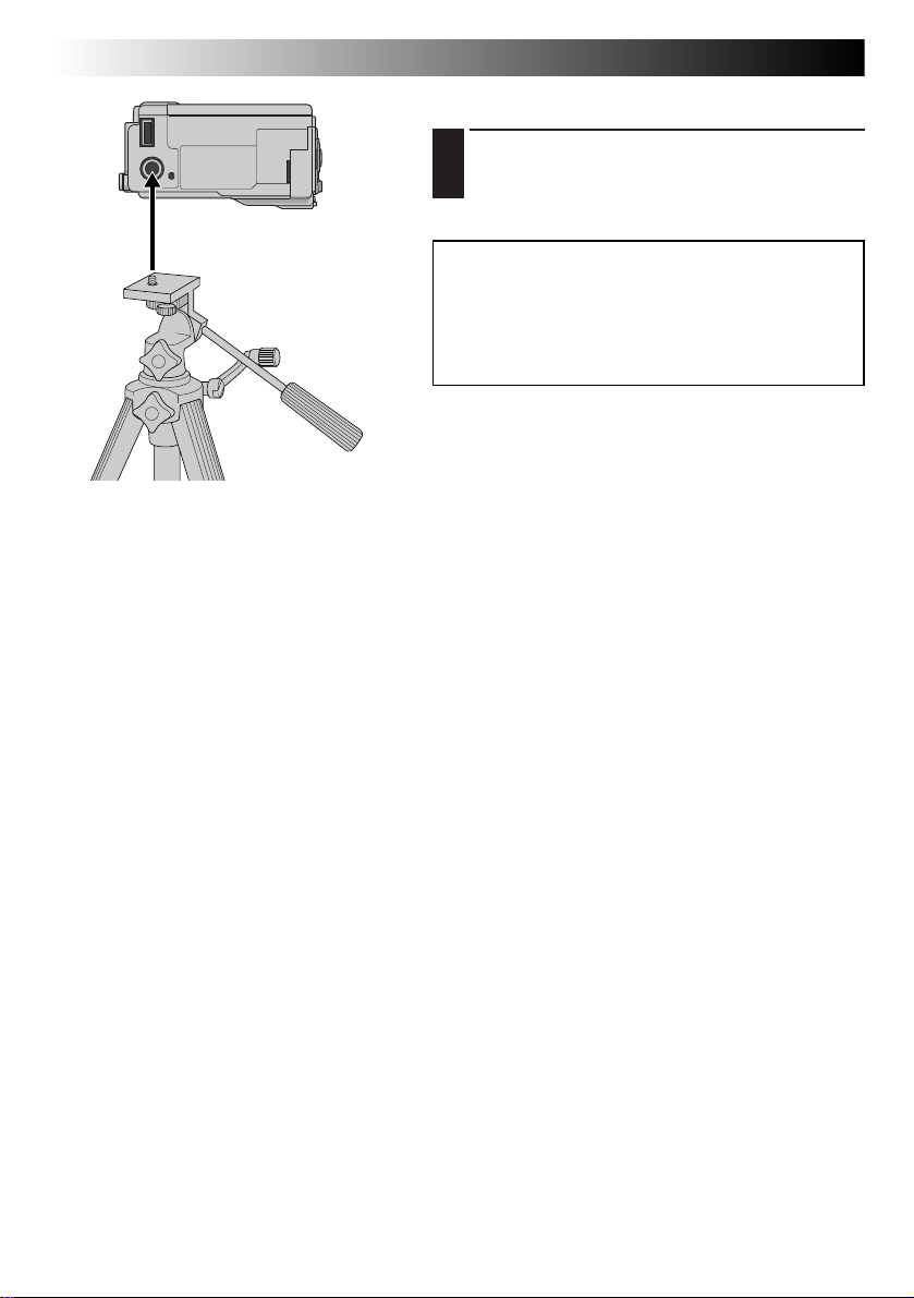
Tripod Mounting
ALIGN AND TIGHTEN
1
Align the screw on the tripod with the camera’s
mounting socket. Then tighten the screw.
CAUTION:
When using a tripod, be sure to open and extend
its legs fully to stabilise the camcorder. To
prevent damage to the unit caused by falling
over, do not use a small-sized tripod.
Page 17
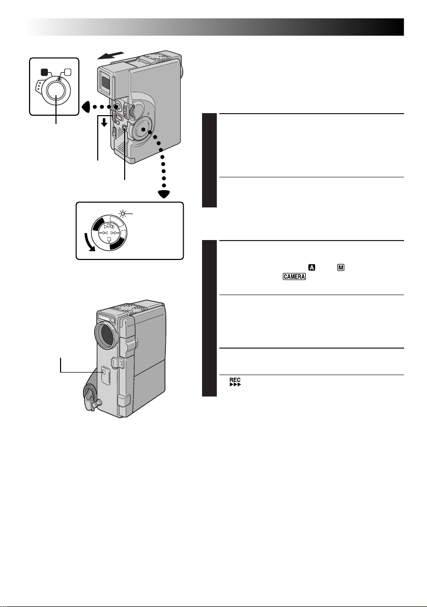
To turn on the camcorder, first set the Power
Switch to any operation mode except “OFF”,
then pull out the viewfinder fully or open the
LCD monitor. When setting the Power Switch,
press and hold the Lock Button.
Lock Button
A M
Operation Switch
P
/
Y
A
L
P
F
C
F
A
O
M
E
C
R
A
5
S
D
S
C
D
S
C
P
L
A
Y
Power Switch
Power lamp
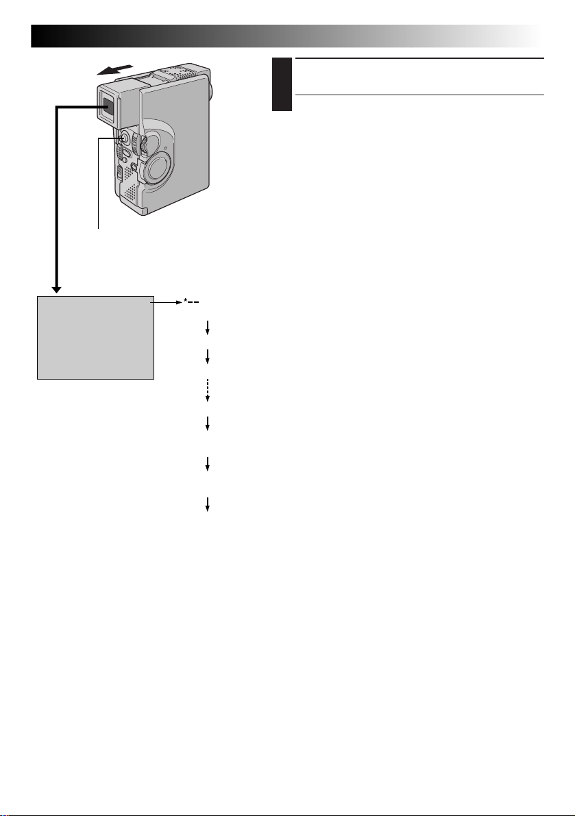
According to the Operation Switch position
you have selected, “F.AUTO” or “MANUAL”
appears in the upper left corner.
F . AUTO
PAUSE
MANUAL
PAUSE
When set to “ ”
When set to “
(When the Power
Switch is set to “5S”,
“MANUAL” blinks.)
”
EN17
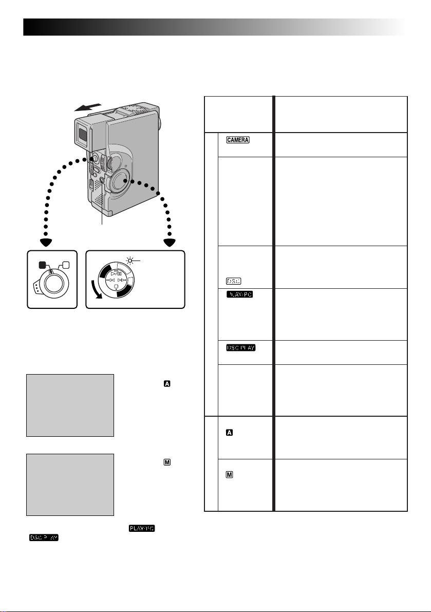
Operation Mode
Turning the Power Switch and Operation Switch allows
you to choose the appropriate operation mode among the
following table:
Power Switch/
Operation Function
Switch Position
Suitable for standard recording on
a tape.
5 second
recording
mode:
5S
Digital
Still
Camera:
Power Switch Position
OFF
Full Auto:
Manual:
Operation Switch Position
Allows you to record on a tape in
5-second clips to keep the action
moving.
Enables shooting in Manual
mode. However, Focus and
Exposure are the same as in the
Full Auto mode, and it is not
possible to change menu settings
using the MENU/SET Dial.
Suitable for standard recording in
the MultiMediaCard.
Allows you to play back a
recording on the tape or to
transfer a still image recorded on
the tape or in the MultiMediaCard
to a computer.
Allows you to display an image
stored in the MultiMediaCard.
Allows you to switch off the
camcorder. After setting to this
position, Manual Focus and
Exposure Control are automatically reset to “AUTO”.
Allows you to record using NO
special effects or manual
adjustments. Suitable for standard
recording.
Allows you to set various
recording functions using the
Menus. If you want more creative
capabilities than Full Auto
recording, try this mode.
If the Power Switch is set to “ ” or
“ ”, these indications do not appear.
Page 18
18 EN
Operation Switch
A M
RECORDING
Basic Recording For Video
NOTE:
You should already have performed the procedures listed
below. If not, do so before continuing.
●
Power (Z pg. 8)
●
Grip Adjustment (Z pg. 10)
●
Viewfinder Adjustment (Z pg. 10)
●
Recording Mode Setting (Z pg. 13)
START/STOP
Button
OPEN/EJECT Switch
Tally lamp
(lights while
recording is
in progress)
Lock Button
F
C
F
A
O
M
E
C
R
P
/
A
Y
A
L
P
C
P
L
A
Y
Power Switch
Power lamp
5
S
D
S
C
D
S
LOAD A CASSETTE
1
Slide OPEN/EJECT in the direction of the arrow then
swing the cover open until it locks. The holder opens
automatically.
Insert a tape and press “PUSH HERE” to close the
cassette holder.
•Once the cassette holder is closed, it recedes
automatically. Wait until it recedes completely
before closing the cassette cover.
Shooting While Watching The Viewfinder
ENTER RECORD-STANDBY MODE
2
Make sure the LCD monitor is closed and locked. Set
the Operation Switch to “ ” or “ ”. Then, set the
Power Switch to “ ” while pressing down the
Lock Button. Pull out the viewfinder fully.
•The lens cover opens, the power lamp lights and the
camcorder enters the Record-Standby mode.
•The scene you are aimed at appears on the
viewfinder screen, with the word “PAUSE”
superimposed upon it.
START SHOOTING
3
Press START/STOP.
•“ ” appears in the viewfinder while recording is
in progress.
Page 19
START/STOP Button
Tape remaining time indicator
25 min
min
(Now calculating)
90 min
89 min
3 min
2 min
(Blinking)
1 min
(Blinking)
0 min
(Blinking)
EN19
STOP RECORDING
4
Press START/STOP again to stop recording.
•The camcorder re-enters the Record-Standby mode.
NOTES:
●
The image will not appear simultaneously in the LCD
monitor and the viewfinder. No image appears on the
LCD monitor when the viewfinder is pulled out. It is not
possible to shoot using both LCD monitor and viewfinder. However, during Interface Shooting (Z pg. 21)
the image appears simultaneously in the LCD monitor
and the viewfinder.
●
The cassette holder cannot be opened unless a power
supply is attached.
●
There may be a delay after you open the cassette cover
until the holder opens. Do not use force.
●
The indicated tape remaining time is approximate.
●
The time required to calculate and to display the
remaining tape length, and the accuracy of the calculation, may vary according to the type of tape used.
●
“TAPE END” appears when the tape reaches its end, and
the power goes off automatically if left in this condition
for 5 minutes. “TAPE END” also appears when a cassette
whose tape is already at its end is loaded.
●
If the Record-Standby mode continues for 5 minutes, the
camcorder’s power shuts off automatically. To turn the
camcorder on again, push back and pull out the
viewfinder again or close and re-open the LCD monitor.
●
When a blank portion is left between recorded scenes
on the tape, the time code is interrupted and errors may
occur when editing the tape. Continue recording from
where you stop so that there are no gaps by following
“Recording from the middle of a tape” (Z pg. 25).
●
During recording, sound is not heard from the speaker. If
you want to hear the sound, connect optional headphones to the headphones connector. The sound
volume at this point is the same as the level it was
adjusted during playback.
●
To turn the tally lamp off during recording, refer to
pgs. 34 – 39.
Page 20
20 EN
Operation Switch
A M
START/STOP Button
Lock Button
Power Switch
F
C
F
A
O
C
P
/
Y
A
L
P
Y
M
E
R
A
5
S
D
S
C
P
L
A
Power lamp
D
S
C
RECORDING
Shooting While Watching The LCD Monitor
Before the following steps, perform step 1 (Z pg. 18).
ENTER RECORD–STANDBY MODE
2
Make sure the viewfinder is pushed back in. Set the
Operation Switch to “ ” or “ ”. Then, set the
Power Switch to “ ” while pressing down the
Lock Button.
Open the LCD monitor fully.
•The lens cover opens, the power lamp lights and the
camcorder enters the Record-Standby mode.
•The scene you are aimed at appears in the LCD
monitor, with the word “PAUSE” superimposed
upon it.
START SHOOTING
3
Tilt the LCD monitor upward/downward for best
viewability (Z pg. 21) and press START/STOP.
•“ ” appears in the LCD monitor while recording
is in progress.
STOP RECORDING
4
Press START/STOP again to stop recording.
•The camcorder re-enters the Record-Standby mode.
NOTES:
●
When you use the LCD monitor outdoors in direct
sunlight, the LCD monitor may be difficult to see. If this
happens, we recommend that you use the viewfinder
(Z pg. 18).
●
To turn the tally lamp off during recording, refer to
pgs. 34 – 39.
●
For other notes, refer to pg. 19.
Basic Recording For Video (cont.)
Tally lamp
(lights while
recording is
in progress)
Page 21
Self-Recording
EN21
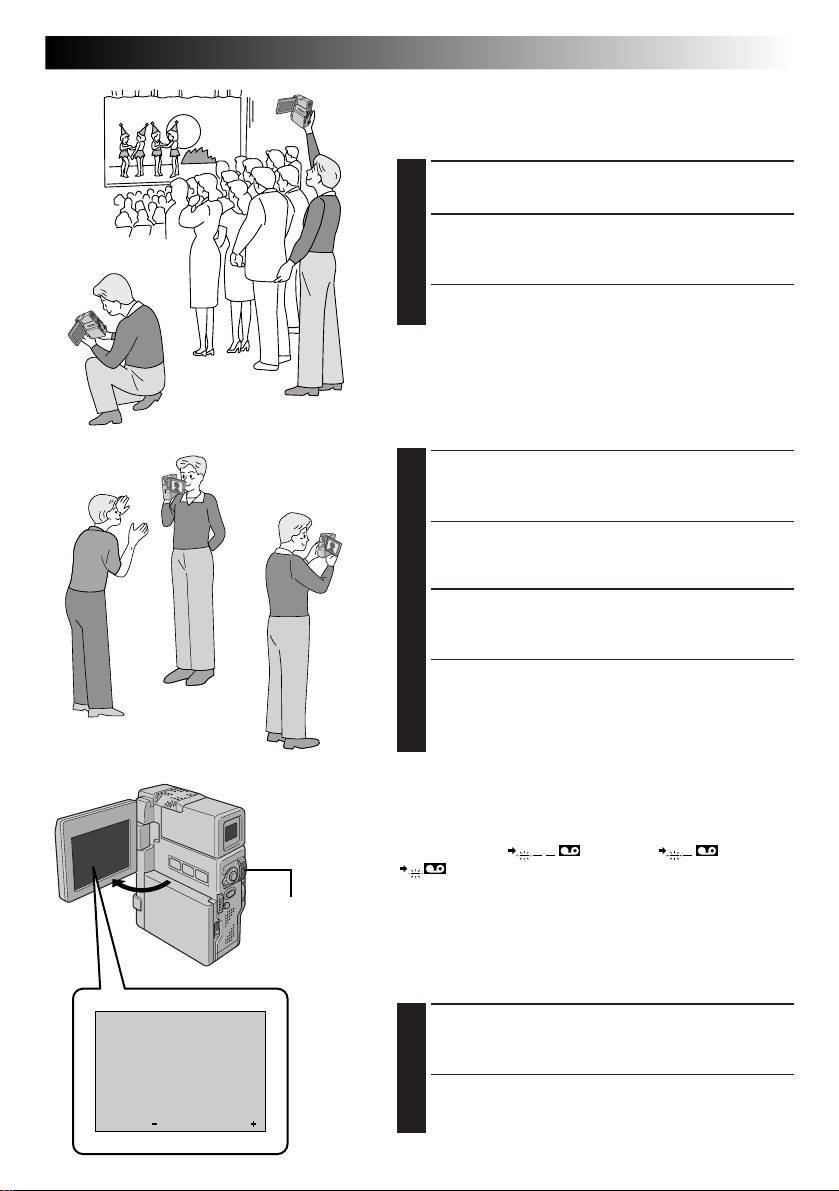
Journalistic Shooting
In some situations different angles of shooting may be
required for more dramatic results.
OPEN LCD MONITOR
1
Make sure the LCD monitor is fully open.
TILT LCD MONITOR
2
Tilt the LCD monitor in the most convenient
direction.
•The LCD monitor can rotate almost full circle (270°:
90° downward, 180° upward).
Interface Shooting
A person you shoot can view himself/herself in the LCD
monitor, and you can even shoot yourself while viewing
your own image in the LCD monitor.
TILT LCD MONITOR UPWARD
1
Open the LCD monitor and tilt it upward to 180
degrees so that it faces forward.
•The monitor image is inverted vertically. If the
viewfinder is pulled out at that time, it will also
switch on.
START RECORDING
2
Point the lens toward the subject (yourself when selfrecording) and start recording.
•During Interface Shooting, the “Tape Running”
indicator and warning indications (Z pg. 102 –
105) are the only ones that are shown; they appear
reversed in the display as they would when viewing
a mirror, but are not reversed in the recording.
NOTE:
The tape remaining indicator does not appear during
interface shooting. However, when the remaining time
reaches 2 minutes, the indicator appears showing the
remaining time: (blinking) (blinking)
(blinking)
BRIGHT
– – – – –
6
– – – – –
MENU/SET
Dial
Brightness Control
You can adjust the brightness of the display by rotating
MENU/SET.
ADJUST BRIGHTNESS
1
Rotate MENU/SET until the brightness indicator moves
and the display reaches its appropriate brightness.
•The brightness indication appears on the display.
•If the viewfinder is pulled out, it is also possible to
adjust its brightness.
Page 22
22 EN
A M
Operation Switch
RECORDING
Lock Button
PHOTO (SNAPSHOT) Button
Power lamp
5
S
A
R
D
E
S
M
C
A
D
C
S
F
C
F
O
P
L
C
A
P
/
Y
Y
A
L
P
Power Switch
Flash
Flash Sensor
SNAPSHOT
MODE Button
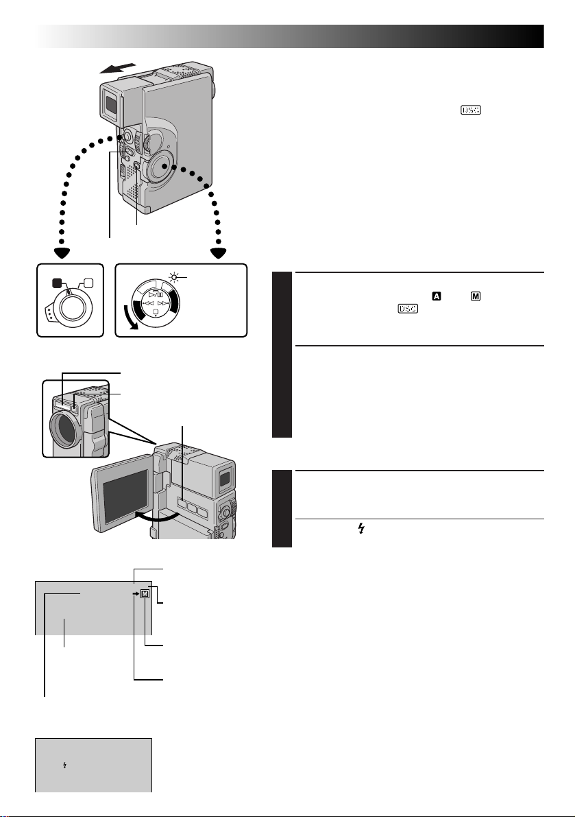
Basic Recording For Digital Still Camera (D.S.C.)
Basic Shooting (Snapshot)
You can use your camcorder as a Digital Still Camera
(D.S.C.) for taking snapshots. Still images shot in the D.S.C.
mode (when the Power Switch is set to “ ”) are
recorded in the MultiMediaCard.
NOTE:
You should already have performed the procedures listed
below. If you haven’t, do so before continuing.
• Power (Z pg. 8)
• Grip Adjustment (Z pg. 10)
• Viewfinder Adjustment (Z pg. 10)
• Loading A MultiMediaCard (Z pg. 14)
• Picture Quality Mode Setting (Z pg. 15)
SNAPSHOT MODE SELECTION
SELECT OPERATION MODE
1
Set the Operation Switch to “ ” or “ ”. Then, set
the Power Switch to “ ” while pressing down the
Lock Button. Open the LCD monitor fully or pull out
the viewfinder fully.
SELECT SNAPSHOT MODE
2
Choose the appropriate mode from among the 5
snapshot modes available (Z pg. 23) by pressing
SNAPSHOT MODE.
Press SNAPSHOT MODE as many times as necessary
until the desired snapshot mode indicator is displayed.
SNAPSHOT RECORDING
TAKE SNAPSHOT
1
Press PHOTO (SNAPSHOT). The image is recorded
in the MultiMediaCard.
•When the “ ” flash ready indicator is displayed,
the flash fires.
Display
STANDARD
FULL
Snapshot mode
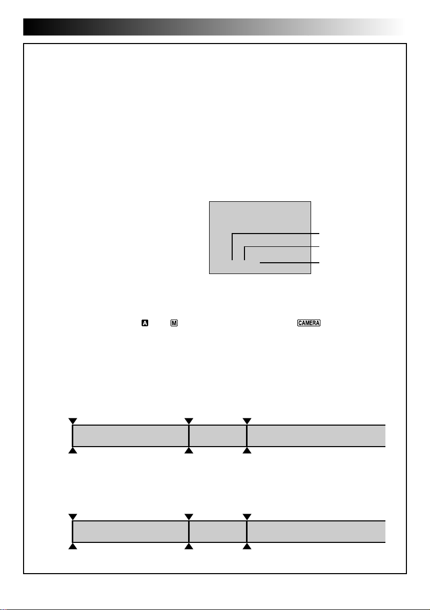
Picture Quality mode
Displays the Picture Quality mode of the stored image. There are 3 modes available:
FINE, STANDARD and ECONOMY (in order of quality).
PHOTO
Number of shots taken
Displays the number of images that have already been shot.
10/38
Total number of shots
Displays the approximate total number of shots that can be stored, including those already
taken. The number increases or decreases depending on the shots stored, the Picture Quality
mode, etc.
Card icon
Appears when a MultiMediaCard is loaded.
Blinks when a MultiMediaCard is not loaded.
Shooting icon
Appears and blinks during shooting.
10/38
During snapshot
MSTANDARD
Page 23
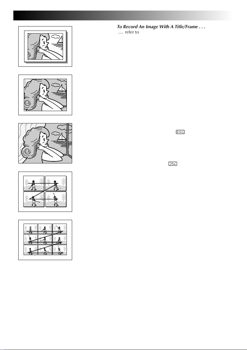
PIN-UP
Pin-Up mode*
FRAME
Snapshot mode
with frame*
FULL
Snapshot mode
with no frame*
MULTI-4
Multi-Analyser 4
EN23
To Record An Image With A Title/Frame . . .
.... refer to “Superimposing A Title/Frame” (Z pg. 69).
To Remove The Shutter Sound . . .
.... when you don’t want to hear the shutter sound, set
BEEP/TALLY to “OFF” in the System Menu
(Z pg. 34 – 39). The sound is no longer hard from the
speaker.
NOTES:
●
Even if “MULTI-4” or “MULTI-9” is engaged, Snapshot
recording will be performed in the FULL mode during
Digital Zoom. However, the flash will not fire.
●
If Snapshot recording is not possible, “PHOTO” blinks
when PHOTO (SNAPSHOT) is pressed.
●
Even if Programme AE with special effects (Z pg. 44,
45) is engaged, certain modes of Programme AE with
special effects are disabled during Snapshot recording.
In such a case, the icon blinks.
●
If shooting is not performed for approx. 5 minutes when
the Power Switch is set to “ ” and power is supplied
from the battery pack, the camcorder shuts off automatically to save power. To perform shooting again, close the
LCD monitor and re-open it. When using the viewfinder,
push back it in and pull it out again.
●
Motor Drive Mode (Z pg. 30) is disabled when the
Power Switch is set to “ ”.
●
To reduce the Red-Eye effect of the subject’s eyes when
the flash fires, Z pg. 32.
●
When a cable or headphone set is connected to the AV
OUT connector, the shutter sound is not heard from the
speaker.
MULTI-9
Multi-Analyser 9
*:There is the sound of a shutter closing.
Page 24
24 EN
Zoom in (T: Telephoto)
D
T
W
W
Digital zoom zone
10X (optical)
zoom zone
D
T
1X
W
T
D
T
10X
20X
W
Zoom out (W: Wide angle)
D
T
10X
W
Approximate zoom ratio
Power Zoom Lever
RECORDING
T
W
D
T
40X
W
Zoom display
Basic Recording For Video And D.S.C.
FEATURE:
PURPOSE:
To produce the zoom in/out effect, or an instantaneous
change in image magnification.
OPERATION:
Zoom In
Slide the Power Zoom Lever towards “T”.
Zoom Out
Slide the Power Zoom Lever towards “W”.
n The further you slide the Power Zoom Lever, the
quicker the zoom action.
NOTES:
●
Focusing may become unstable during Zooming. In
this case, set the zoom while in Record-Standby,
lock the focus by using the manual focus
(Z pg. 47), then zoom in or out in Record mode.
●
In Full Auto mode (when the Operation Switch is
set to “ ”), zoom magnification of up to 40X is
possible. In Manual mode (when the Operation
Switch is set to “ ”), zooming is possible to a
maximum of 200X or can be switched to 10X
magnification offered by optical zoom.
●
Zoom magnification of over 10X is done through
Digital image processing, and is therefore called
Digital Zoom.
●
During Digital zoom, the quality of image may
suffer.
●
Digital zoom cannot be used while functions done
through Digital image processing (Picture Wipe/
Dissolve function, Z pg. 42, Video Echo,
Z
●
Macro shooting (as close as approx. 5 cm to the
subject) is possible when the Power Zoom Lever is
set all the way to “W”. Also see “TELE MACRO” in
the System Menu on page 39.
Zooming
pg. 45, etc.) are activated.
A M
Operation Switch
F
C
F
A
O
M
E
C
R
P
/
A
Y
5
A
L
P
S
C
P
L
A
Y
Power Switch
Power lamp
S
D
S
C
D
Page 25
EN25
NOTE: Recording From The Middle Of A Tape
Time Code
During recording, a time code is recorded on the tape. This code is to confirm the location of the recorded
scene on the tape during playback.
If recording starts from a blank portion, the time code begins counting from “00:00:00”
(minute:second:frame). If recording starts from the end of a previously recorded scene, the time code
continues from the last time code number.
To perform Random Assemble Editing (Z pg. 84 – 89), time code is necessary. If during recording a blank
portion is recorded partway through the tape, the time code is interrupted. When recording is resumed, the
time code starts counting up again from “00:00:00”. This means the camcorder may record the same time
codes as those existing in a previously recorded scene. To prevent leaving a blank portion on a tape,
perform the procedure in “Recording From The Middle of A Tape” (see below) in the following cases;
•After playing back the recorded tape, when you
shoot again.
•When power shuts off during shooting.
•When a tape is removed and re-inserted during
shooting.
•When shooting using a partially recorded tape.
•When shooting on a blank portion located
partway through the tape.
•When shooting again after already shooting a
scene and opening/closing the cassette cover.
TC
Recording From The Middle Of A Tape
1. Play back a tape to find the spot at which you want to start recording, then engage the Still Playback
mode (Z pg. 53).
2. Set the Operation Switch to “ ” or “ ”. Then, set the Power Switch to “ ” or “5S” while
pressing down the Lock Button and start recording.
NOTES:
●
The Time Code cannot be reset.
●
During fast-forwarding and rewinding, time code indication does not move smoothly.
Display
12 : 34 : 24
Time code is displayed
during playback.
Minutes
Seconds
Frames
(25 frames = 1 second)
When blank portion is recorded on a tape
Time code
00:00:00
Tape
Shooting start point
Time code
05:43:21
Proper recording
Time code
00:00:00
Tape
Shooting start point
Time code
05:43:21
Time code
00:00:00
Shooting start pointShooting stop point
Time code
05:44:00
Shooting start pointShooting start point
Newly recorded sceneBlankAlready recorded scene
Latest sceneNew sceneAlready recorded scene
Page 26
26 EN
OFF
FLASH ADJ.
P. AE
/ EFFECT
END
0
4
– – – – –6– – – – –
4
TO DATE / TIME MENU
TO SYSTEM MENU
END
OFF
AUTO
FLASH
GAIN UP AGC
SELF-TIMER
Operation Switch
A M
MENU/SET Dial Power Switch
Display
TO MODE MENU
RECORDING
Lock Button
F
C
F
A
O
M
E
C
P
/
Y
A
L
P
P
L
A
Y
Recording Menu
Mode Menu
R
A
5
S
D
S
C
D
S
C
Power lamp
Advanced Features For Video And D.S.C.
Displaying The Date And Time During
RECORDING
Advanced Features
Recording
When the Operation Switch is set to “ ”, you can choose
whether to display the date and time during recording or
not. You must first set the date and time (“Date/Time
Settings”, Z pg. 11). Set “DISPLAY” to “ON” in the Date/
Time Menu. The Date/Time is always displayed when the
Operaton Switch is set to “ ”.
SELECT OPERATION MODE
1
Set the Operation Switch to “ ”. Then, set the
Power Switch to “ ”, “5S” or “ ” while
pressing down the Lock Button.
ACCESS RECORDING MENU
2
Press MENU/SET. The Recording Menu appears.
ACCESS MODE MENU
3
Move the highlight bar to “TO MODE MENU” by
rotating MENU/SET. Press it and the Mode Menu
appears.
ACCESS DATE/TIME MENU
4
Move the highlight bar to “TO DATE/TIME MENU”
by rotating MENU/SET. Press it and the Date/Time
Menu appears.
SELECT FUNCTION
5
Move the highlight bar to “DISPLAY” by rotating
MENU/SET, then press it.
SET FUNCTION PARAMETERS
6
Cycle through the available settings of the selected
functions by rotating MENU/SET and stop when the
one you want is displayed. Then press it and the
highlight bar automatically moves to “RETURN”.
INDICATION ON
ON SCREEN OFF
DATE / TIME
4
RETURN
DATE/TIME
ONDISPLAY
25 . 12 . 99
16 : 40
Date/Time Menu
CLOSE RECORDING MENU
7
Press MENU/SET twice. Selection is complete and the
menu disappears.
NOTES:
●
Connect the camcorder to a TV and set “ON SCREEN”
to “ON” in the Date/Time Menu. The display appears on
the connected TV .
●
Even if “ON SCREEN” is set to “ON”, the indications are
removed from the TV if “INDICATION” is set to “OFF”
(Z pg. 27).
Page 27
OFF
FLASH ADJ.
P. AE
/ EFFECT
END
0
4
– – – – –6– – – – –
4
TO DATE / TIME MENU
TO SYSTEM MENU
END
OFF
AUTO
FLASH
GAIN UP AGC
SELF-TIMER
Operation Switch
A M
Lock Button
EN27
LCD Monitor/Viewfinder Indications
You can make the LCD monitor/Viewfinder indications
appear/disappear.
SELECT OPERATION MODE
1
Set the Operation Switch to “ ”. Then, set the
Power Switch to “ ”, “5S” or “ ” while
pressing down the Lock Button.
ACCESS RECORDING MENU
2
Press MENU/SET. The Recording Menu appears.
ACCESS MODE MENU
3
Move the highlight bar to “TO MODE MENU” by
rotating MENU/SET. Press it and the Mode Menu
appears.
Power lamp
F
C
F
A
O
M
E
C
R
P
/
A
Y
5
A
S
L
P
D
S
C
D
S
C
P
L
A
Y
MENU/SET Dial Power Switch
Display
Recording Menu
TO MODE MENU
Mode Menu
DATE/TIME
INDICATION ON
ON SCREEN OFF
DATE / TIME
4
RETURN
ONDISPLAY
25 . 12 . 99
Date/Time Menu
16 : 40
ACCESS DATE/TIME MENU
4
Move the highlight bar to “TO DATE/TIME MENU”
by rotating MENU/SET. Press it and the Date/Time
Menu appears.
SELECT FUNCTION
5
Move the highlight bar to “INDICATION” by rotating
MENU/SET, then press it.
SET FUNCTION PARAMETERS
6
Cycle through the available settings of the selected
functions by rotating MENU/SET and stop when the
one you want is displayed.
OFF: To make the indications disappear.
ON: To make the indications appear.
Then press it and the highlight bar automatically
moves to “RETURN”.
CLOSE RECORDING MENU
7
Press MENU/SET twice. Selection is complete and the
menu disappears.
NOTES:
●
It is impossible to make the tape running indicator
“
444
” and warnings etc. disappear from the LCD
monitor or the viewfinder. For the indications that can
be removed, Z pg. 102, 103.
●
If “INDICATION” is set in the Date/Time Menu,
“INDICATION” in the Playback Menu will also be set to
the same setting (Z pg. 55).
Page 28
28 EN
Operation Switch
A M
START/STOP Button
PHOTO (SNAPSHOT)
Button
Display
MANUAL
5S MODE
MANUAL
5S MODE
RECORDING
Lock Button
E
R
M
A
A
5
C
S
F
D
F
O
C
P
/
Y
A
L
P
Y
Power Switch
REC
PAUSE
PAUSE
444
After 5 sec.
REC
444
Record-Standby
S
C
D
S
C
P
L
A
Power lamp
Advanced Features For Video And D.S.C. (cont.)
Scene (5-second recording)
Record a vacation or an important event in 5-second clips
to keep the action moving. This function is available only
for video recording.
SELECT OPERATION MODE
1
Set the Operation Switch to “ ” or “ ”, then set
the Power Switch to “5S” while pressing down the
Lock Button. Pull out the viewfinder fully or open the
LCD monitor fully.
•“5S MODE” appears.
ENGAGE 5S MODE
2
Press START/STOP. The tally lamp lights and beep
sounds to indicate the start of recording, and after 5
seconds the camcorder enters Record-Standby mode.
•If you press START/STOP again within 5 seconds
after recording starts, Record-Standby mode is not
engaged.
•If you press and hold START/STOP, recording
continues until START/STOP is released.
END 5S MODE
3
Set the Power Switch to “ ” or “OFF”.
To Take A Snapshot In The 5-Second Recording Mode . . .
.... instead of pressing START/STOP in step 2, press
SNAPSHOT MODE as many times as necessary until
the desired snapshot indicator is displayed, then press
PHOTO (SNAPSHOT). The camcorder records a 5second still (Z pg. 30). When “SCENE” is set to
“ANIM.” (Z pg. 34 – 39) this function is not
available.
NOTES:
●
When “SCENE” is set to “ANIM.” in the System Menu,
the 5-second recording mode is not available. Animation recording of a 1/3-second clip is taken instead
(Z pg. 34 – 39).
●
While the 5-second recording mode is activated, Fade/
Wipe effects (Z pg. 43) and Programme AE with
special effects (Z pg. 45) cannot be performed.
However, when “SCENE” is set to “5SD” in the System
Menu (Z pg. 39), the Dissolve function is available (see
below).
Dissolves during 5 second recording mode
Set “SCENE” to “5SD” in the System Menu (Z pg. 34 –
39). “5SD MODE” appears in step 1. Record one 5-second
clip, and the image at the end of the clip is stored. If you
record the next clip within 5 minutes, the previous scene
dissolves as the new scene appears.
•If you turn the power off, the stored image will be lost.
Dissolves during 5 second recording mode
Page 29
OFF
FLASH ADJ.
P. AE
/ EFFECT
END
0
4
– – – – –6– – – – –
4
TO DATE / TIME MENU
TO SYSTEM MENU
END
ON
AUTO
FLASH
GAIN UP AGC
SELF-TIMER
Operation Switch
A M
START/STOP
Button
Lock Button
EN29
Self-Timer
Once the camcorder is set, the camcorder operator can
become part of the scene in a more natural way, adding
the final touch to a memorable picture.
SELECT OPERATION MODE
1
Set the Operation Switch to “ ”. Then, set the
Power Switch to “ ” or “ ” (or “5S”) while
pressing down the Lock Button. Pull out the
viewfinder fully or open the LCD monitor fully.
•You can tilt the LCD monitor upward to 180
degrees so that it faces forward and view yourself
while self-recording with the viewfinder pushed
back.
MENU/SET Dial
Display
TO MODE MENU
MANUAL
PAUSE
F
C
F
A
O
M
E
C
R
P
/
Y
A
L
P
P
L
A
Y
Power Switch
Recording Menu
Mode Menu
– – –
Self-Timer
indication
A
5
S
D
S
C
D
S
C
Power lamp
ACCESS RECORDING MENU
2
Press MENU/SET. The Recording Menu appears.
ACCESS MODE MENU
3
Move the highlight bar to “TO MODE MENU” by
rotating MENU/SET. Press it. The Mode Menu
appears.
SET SELF-TIMER
4
Move the highlight bar to “SELF-TIMER” by rotating
MENU/SET. Press it and the parameter is highlighted.
Rotate MENU/SET until “ON” appears. Press it twice
to exit from the Recording Menu.
ENGAGE SELF-TIMER MODE
5
Press START/STOP. After 15 seconds, the beep
sounds and video recording starts. To stop Self-Timer
recording, press START/STOP again. The camcorder
re-enters Record-Standby mode.
OR
Press PHOTO (SNAPSHOT). After 15 seconds, the
beep sounds and snapshot recording starts. After that,
the camcorder re-enters Record-Standby mode.
END SELF-TIMER RECORDING
6
Set the Operation Switch to “ ” or set the Power
Switch to “OFF”. “SELF-TIMER” is automatically set
back to “OFF”.
When START/STOP or
PHOTO (SNAPSHOT)
is pressed, the tally
lamp changes as shown:
Begins blinking
(Self-Timer starts)
Blinks quickly
¥¥
(Self-Timer shooting
starts soon)
After approx. 15 sec.
Stops blinking
and stays on
(Self-Timer
4
shooting starts)
Page 30
30 EN
A M
Operation Switch
RECORDING
Lock Button
PHOTO (SNAPSHOT) Button
Power lamp
F
C
F
A
O
M
E
C
R
P
/
A
Y
5
A
S
L
P
D
S
C
D
S
C
P
L
A
Y
Power Switch
Advanced Features For Video And D.S.C. (cont.)
Snapshot (For Video Recording)
Use your camcorder like a regular camera and take a
snapshot, or several of them in succession.
This feature lets you record still images that look like
photographs onto a tape.
SNAPSHOT MODE SELECTION
SELECT OPERATION MODE
1
Set the Operation Switch to “ ” or “ ”. Then, set
the Power Switch to “ ” while pressing down
the Lock Button. Pull out the viewfinder fully or open
the LCD monitor fully.
SELECT SNAPSHOT MODE
2
Choose the appropriate mode from among the 5
Snapshot modes (Z pg. 31) by pressing SNAPSHOT
MODE.
Press SNAPSHOT MODE as many times as necessary
until the desired snapshot mode indicator is displayed.
SNAPSHOT RECORDING
TAKE SNAPSHOT
1
Press PHOTO (SNAPSHOT).
If you press during Record-Standby . . .
.... “PHOTO” appears and a still image will be
recorded for approx. 6 seconds, then the
camcorder re-enters the Record-Standby mode.
If you press during Recording . . .
.... “PHOTO” appears and a still image will be
recorded for approx. 5 seconds, then the normal
recording resumes.
•When the “ ” flash ready indicator is displayed,
the flash fires.
FULL
PHOTO
SNAPSHOT MODE Button
Display
Snapshot mode
During snapshot
Motor Drive Mode
Keeping PHOTO (SNAPSHOT) pressed provides an effect
similar to serial photography. (The interval between the
still images: approx. 1 second.) However, when “REC
SELECT” is set to “TAPE & CARD” in the System Menu (Z
pg. 39), the Motor Drive Mode does not take place.
To Remove The Shutter Sound. . .
.... when you don’t want to hear the shutter sound, set
BEEP/TALLY to “OFF” in the System Menu
(Z pg. 34 – 39). Though the sound is not heard from
the speaker, it is recorded on the tape.
Page 31

PIN-UP
Pin-Up mode*
FRAME
Snapshot mode
with frame*
FULL
Snapshot mode
with no frame*
MULTI-4
Multi-Analyser 4
EN31
NOTES:
●
Even if “MULTI-4” or “MULTI-9” is engaged, Snapshot
recording will be performed in the FULL mode during
Digital Zoom. However, the flash will not fire.
●
If Snapshot recording is not possible, “PHOTO” blinks
when PHOTO (SNAPSHOT) is pressed.
●
Even if Programme AE with special effects (Z pg. 44) is
engaged, certain modes of Programme AE with special
effects are disabled during Snapshot recording. In such a
case, the icon blinks.
●
When “REC SELECT” is set to “TAPE & CARD” in the
System Menu (Z pg. 39), still images are recorded not
only onto the tape but also in the MultiMediaCard. If a
tape is not loaded, they are recorded only in the
MultiMediaCard, and if a MultiMediaCard is not loaded,
the message “COPYING FAILED” appears and still
images are recorded only onto the tape.
●
If PHOTO (SNAPSHOT) is pressed during tape
playback . . .
•
If a MultiMediaCard is not loaded: The message
“COPYING FAILED” will appear, and a still image
produced by the Snapshot mode will be displayed, in
the same manner as during recording.
•
If a MultiMediaCard is loaded: A still image produced
by the Snapshot mode will be recorded in the
MultiMediaCard (Z pg. 77).
●
To reduce the Red-Eye effect of the subject’s eyes when
the flash fires, Z pg. 32.
●
When a cable or headphone set is connected to the AV
OUT connector, the shutter sound is not heard from the
speaker, however it is recorded onto the tape.
MULTI-9
Multi-Analyser 9
*:There is the sound effect of a shutter closing.
Page 32
32 EN
FLASH ADJ.
END
0
4
– – – – –6– – – – –
4
TO DATE / TIME MENU
TO SYSTEM MENU
END
AUTO
FLASH
Operation Switch
A M
MENU/SET Dial
TO MODE MENU
RECORDING
PHOTO
(SNAPSHOT)
Button
Lock Button
C
P
/
Y
A
L
P
Display
Power lamp
F
C
F
A
O
M
E
R
A
5
S
D
S
C
D
S
C
P
L
A
Y
Power Switch
Recording Menu
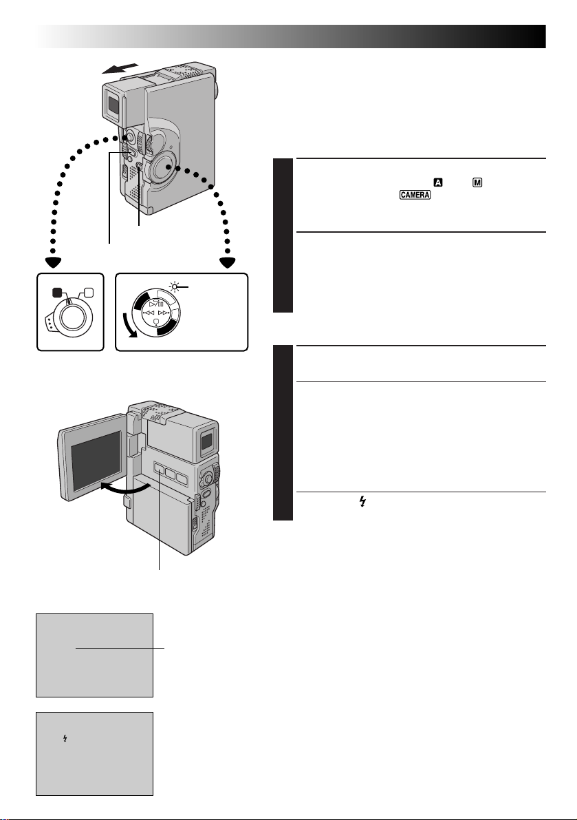
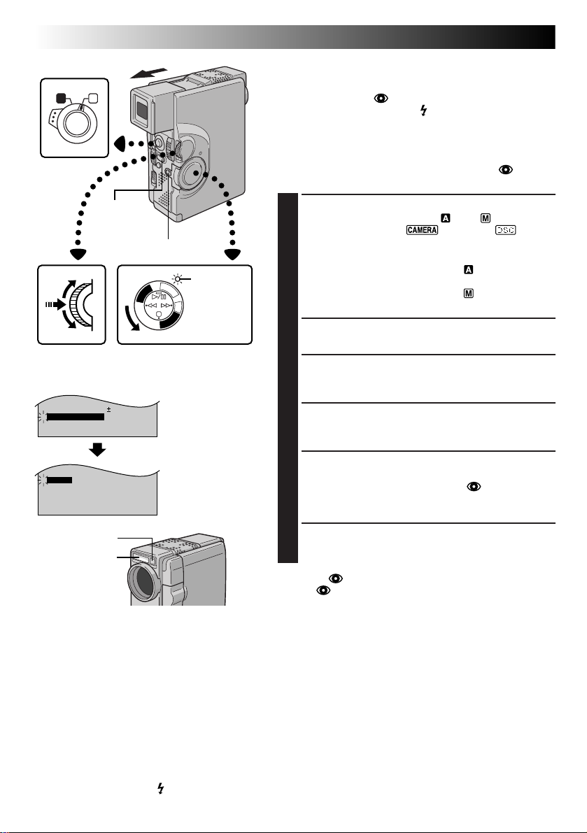
Advanced Features For Video And D.S.C. (cont.)
Snapshot Flash (Auto Flash)
In Full Auto or Manual mode, when “FLASH” is set to
“AUTO” or “AUTO ” in the Mode Menu, the flash
automatically fires if it’s dark ( appears) when a snapshot
is taken in Record-Standby.
By setting “FLASH” to “ON” or “OFF” in the Mode Menu,
the flash can be activated or deactivated on demand.
To reduce the Red-Eye effect in the subject’s eyes, it is
recommended that you set “FLASH” to “AUTO ”. The
flash automatically fires using this function when it is dark.
ENGAGE RECORD-STANDBY
1
Set the Operation Switch to “ ” or “ ”. Then, set
the Power Switch to “ ”, “5S” or “ ” while
pressing down the Lock Button. Pull out the viewfinder fully or open the LCD monitor fully.
If the Operation Switch is set to “ ” . . .
.... go to step 6.
If the Operation Switch is set to “ ” . . .
.... go to step 2.
ACCESS RECORDING MENU
2
Press MENU/SET. The Recording Menu appears.
ACCESS MODE MENU
3
Move the highlight bar to “TO MODE MENU” by
rotating MENU/SET. Press it. The Mode Menu appears.
SELECT FUNCTION
4
Rotate MENU/SET to move the highlight bar to
“FLASH”, then press it.
SELECT FUNCTION PARAMETERS
5
Mode Menu
Rotate MENU/SET to display the desired parameter
(“AUTO”, “ON”, “OFF” or “AUTO ”) and press it.
The parameter stops blinking and setting is complete.
Press MENU/SET. The normal screen reappears.
Flash sensor
Flash
TAKE SNAPSHOT
6
Press PHOTO (SNAPSHOT).
If “AUTO ” Is Selected In The Mode Menu . . .
.... the Red-Eye reduction indicator lights, then press
PHOTO (SNAPSHOT). The flash fires twice. The first
flash is for reduction of the human eye’s red reflection
and the second flash is for the actual recording.
NOTES:
●
Do not fire the flash at a person at short range.
●
In Multi-Analyser 4 or Multi-Analyser 9, the flash is disabled (Z pg. 23, 31).
●
The flash does not fire when the flash is set to “OFF” on the Mode Menu and also when the battery remaining
power is low. Moreover, the flash does not fire when it is set to “AUTO” on the Mode Menu with GAIN UP set to
“OFF” (Z pg. 37) and with Programme AE with special effects set to “TWILIGHT” (Z pg. 45).
●
When taking several snapshots in succession (Motor Drive Mode), the flash fires only during the first one.
●
Although images shot with a flash tend to look whiter than they actually are, to compensate for this the camcorder
automatically darkens the picture when using the flash. When shooting a subject at a distance where the flash light
cannot reach (over approx. 2 m), set the flash to “OFF” to prevent the picture from becoming too dark.
●
The colour tone changes depending on the background lighting conditions, such as under fluorescent or halogen
lamps.
●
When you want to change the brightness of the flash, refer to “Flash Brightness Adjustment” (Z pg. 33).
●
While charging the flash, blinks and the flash will not fire. Although noise may appear, this is not a malfunction
and is not recorded. It can take up to ten seconds to charge the flash.
Page 33
FLASH ADJ.
END
0
4
– – – – –6– – – – –
TO MODE MENU
END
Operation Switch
A M
EN33
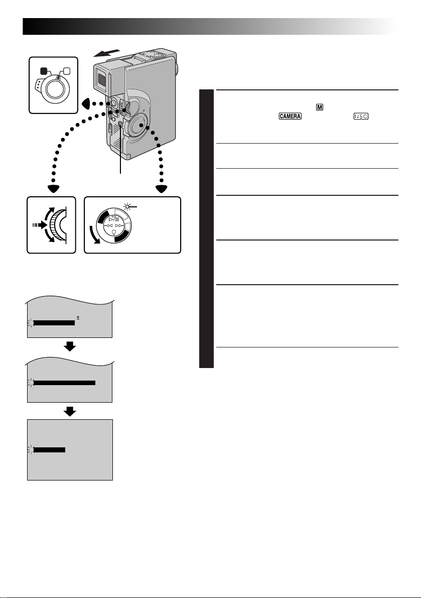
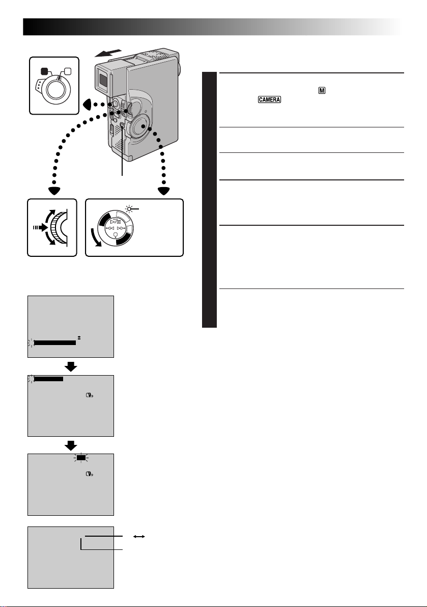
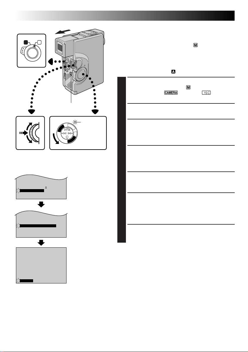
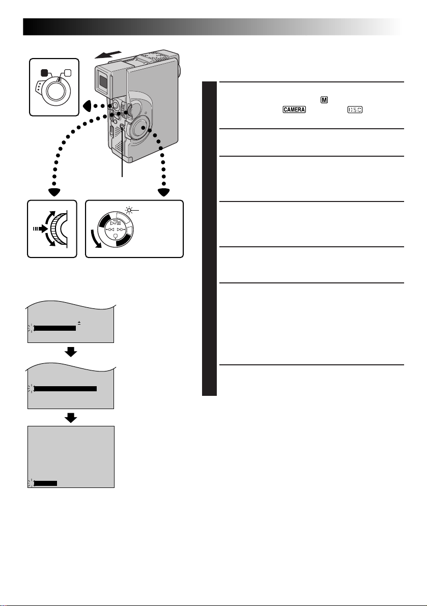
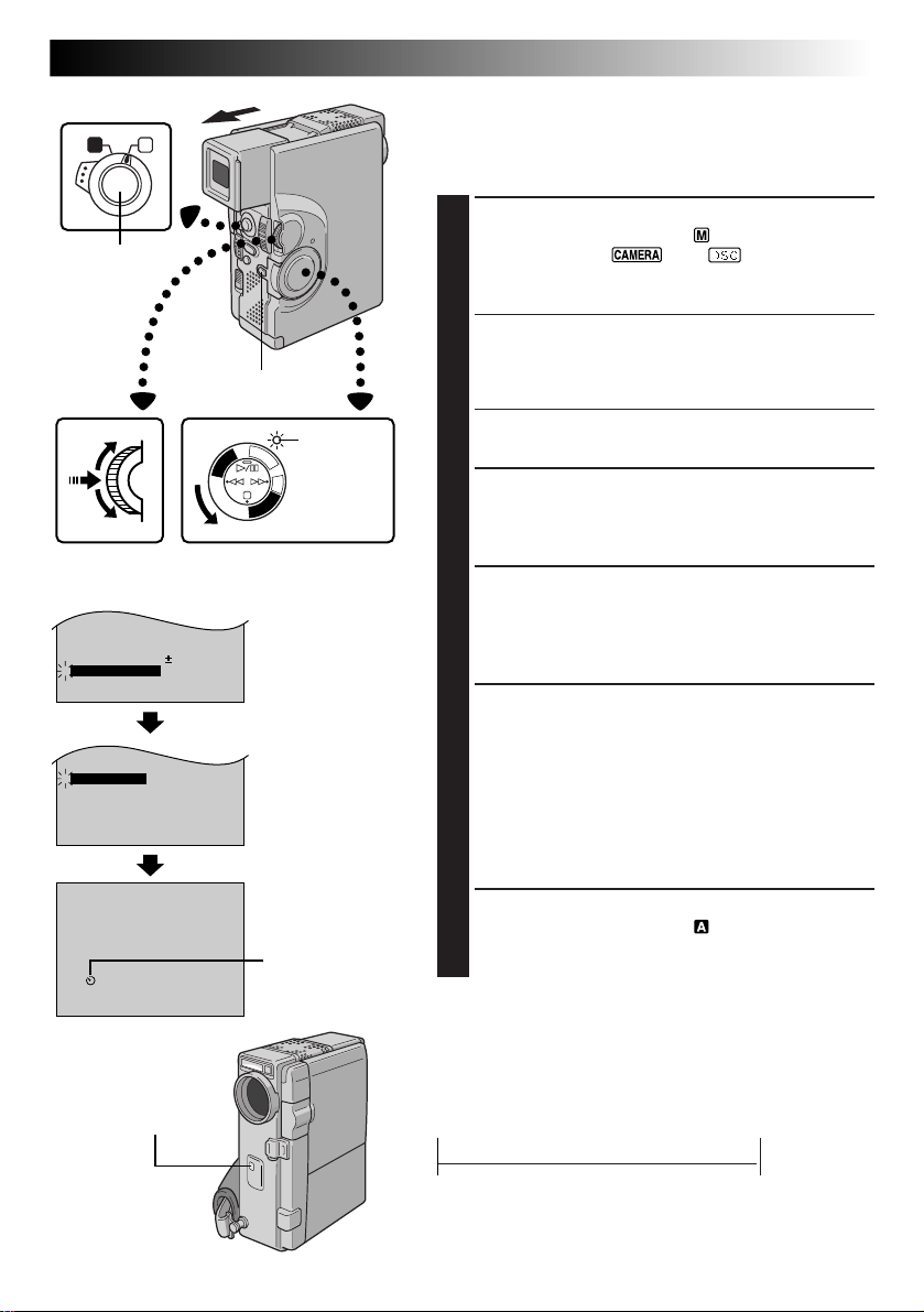
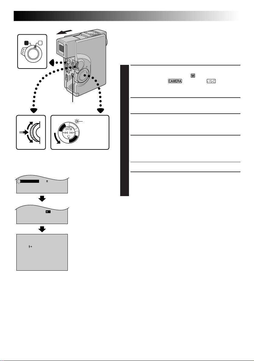
Flash Brightness Adjustment
When a snapshot (Z pg. 22, 30) is taken in the dark the
camcorder fires the flash (Z pg. 32) and adjusts the
brightness automatically. You can also adjust the flash
brightness manually. When you find that the snapshots
you took look too bright or too dark, adjust it manually.
SELECT OPERATION MODE
1
Set the Operation Switch to “ ”. Then, set the
Power Switch to “ ”, “5S” or “ ” while
pressing down the Lock Button. Pull out the viewfinder fully or open the LCD monitor fully.
Lock Button
Power lamp
F
C
F
A
O
M
E
C
R
P
/
A
Y
5
A
S
L
P
D
S
C
D
S
C
P
L
A
Y
MENU/SET Dial Power Switch
Display
TO MODE MENU
4
FLASH ADJ.
MANUAL
2
2
Recording Menu
ACCESS RECORDING MENU
2
Press MENU/SET. The Recording Menu appears.
SELECT FUNCTION
3
Rotate MENU/SET to move the highlight bar to
“FLASH ADJ.”, then press it. The parameter blinks.
ADJUST BRIGHTNESS OF FLASH
4
Rotating MENU/SET upward increases the number of
the brightness adjustment and rotating MENU/SET
downward decreases it.
•The adjustment range is from –3 to +3.
ACTIVATE BRIGHTNESS OF FLASH
5
Press MENU/SET twice. The flash brightness
adjustment is complete and the normal screen
reappears.
NOTES:
●
When the battery power is low or when “FLASH” is set
to “OFF” in the Mode Menu, the “FLASH ADJ.” setting
cannot be changed.
●
When you change the subject you are shooting or the
shooting location, set it back to ±0 as described in step 4
and take a snapshot to check the flash brightness. After
doing this adjust to your desired brightness.
Page 34
34 EN
Operation Switch
A M
RECORDING
Advanced Features For Video And D.S.C. (cont.)
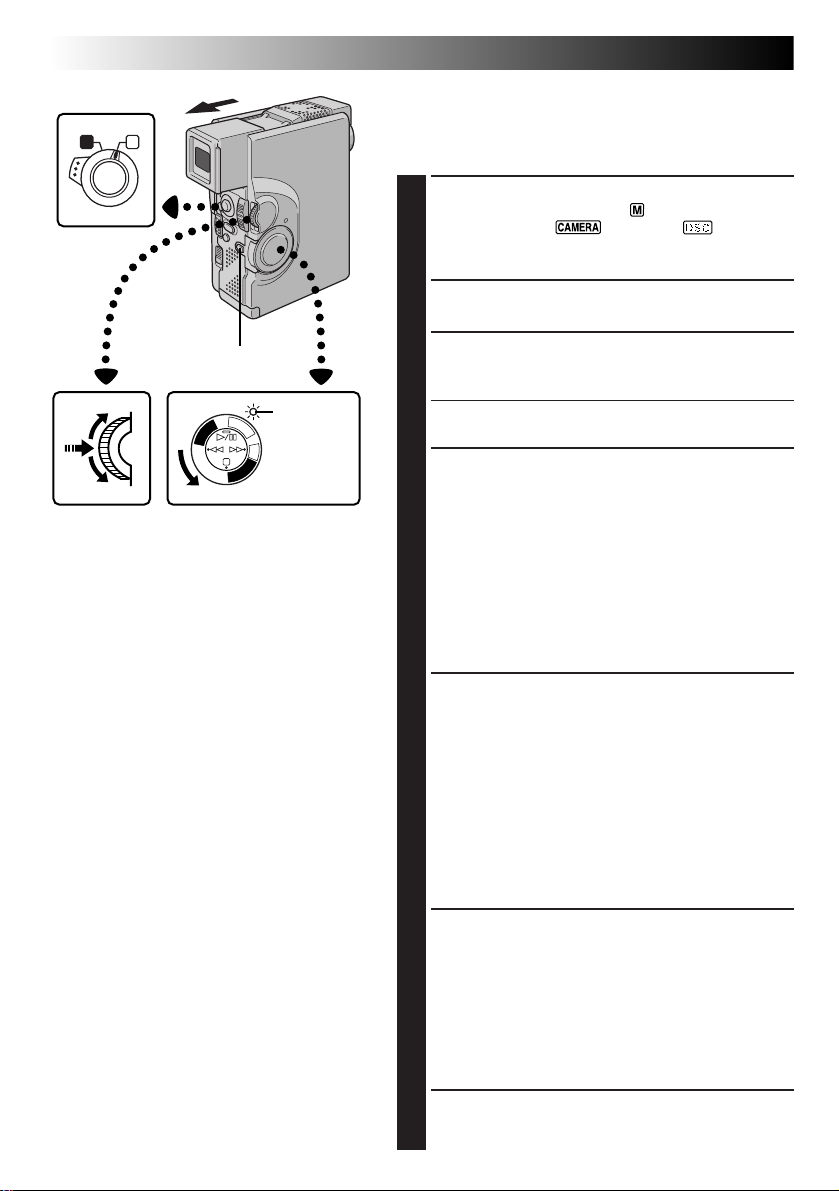
Using Menu For Detailed Adjustment
This camcorder is equipped with an easy-to-use,
on-screen menu system that simplifies many of the more
detailed camcorder settings (Z pg. 35 – 39) .
SELECT OPERATION MODE
1
Set the Operation Switch to “ ”. Then, set the
Power Switch to “ ”, “5S” or “ ” while
pressing down the Lock Button. Pull out the viewfinder fully or open the LCD monitor fully.
ACCESS RECORDING MENU
2
Press MENU/SET. The Recording Menu appears.
Lock Button
F
C
F
A
O
M
E
C
R
P
/
A
Y
5
A
S
L
P
D
S
C
D
S
C
P
L
A
Y
Power SwitchMENU/SET Dial
Power lamp
SELECT FUNCTION
3
Rotate MENU/SET to move the highlight bar to the
desired function.
• If the setting you want cannot be found in the Menu
Screen, place the highlight bar on “END”, then go to step 7.
MAKE SETTING
4
Press MENU/SET. The setting procedure depends on
the function you select.
If you select “FOCUS”, “EXPOSURE”, “W.BALANCE”,
“FADER/WIPE”, “P.AE/EFFECT” or “FLASH ADJ.” . . .
..... see respective pages (FOCUS: Z pg. 47,
EXPOSURE: Z pg. 48, W.BALANCE: Z pg. 50,
FADER/WIPE: Z pg. 41, P.AE/EFFECT: Z pg. 44,
FLASH ADJ.,: Z pg. 33) and do each procedure
from step 4.
If you select “TO MODE MENU” . . .
..... the Mode Menu appears. Go to step 5.
SELECT FUNCTION PARAMETERS IN
5
MODE MENU
Rotate MENU/SET to move the highlight bar to the
desired function and press it.
If you select a function other than “TO DATE/TIME
MENU” or “TO SYSTEM MENU” . . .
..... each function’s parameter starts blinking. Rotate MENU/
SET until the desired parameter appears. Go to step 7.
If you select “TO DATE/TIME MENU” . . .
..... the Date/Time Menu appears. Go to step 6.
If you select “TO SYSTEM MENU” . . .
..... the System Menu appears. Go to step 6.
SELECT FUNCTION PARAMETERS IN
6
DATE/TIME MENU OR SYSTEM MENU
Rotate MENU/SET to move the highlight bar to the
desired function, then press it.
If you select “DATE/TIME” . . . Z pg. 11.
If you select other functions . . .
..... rotate MENU/SET until the desired parameter
appears, then press it. The highlight bar automatically moves to “RETURN”. Go to step 7.
CLOSE MENU SCREEN
7
Press MENU/SET as many times as necessary to
return to the normal screen.
Page 35
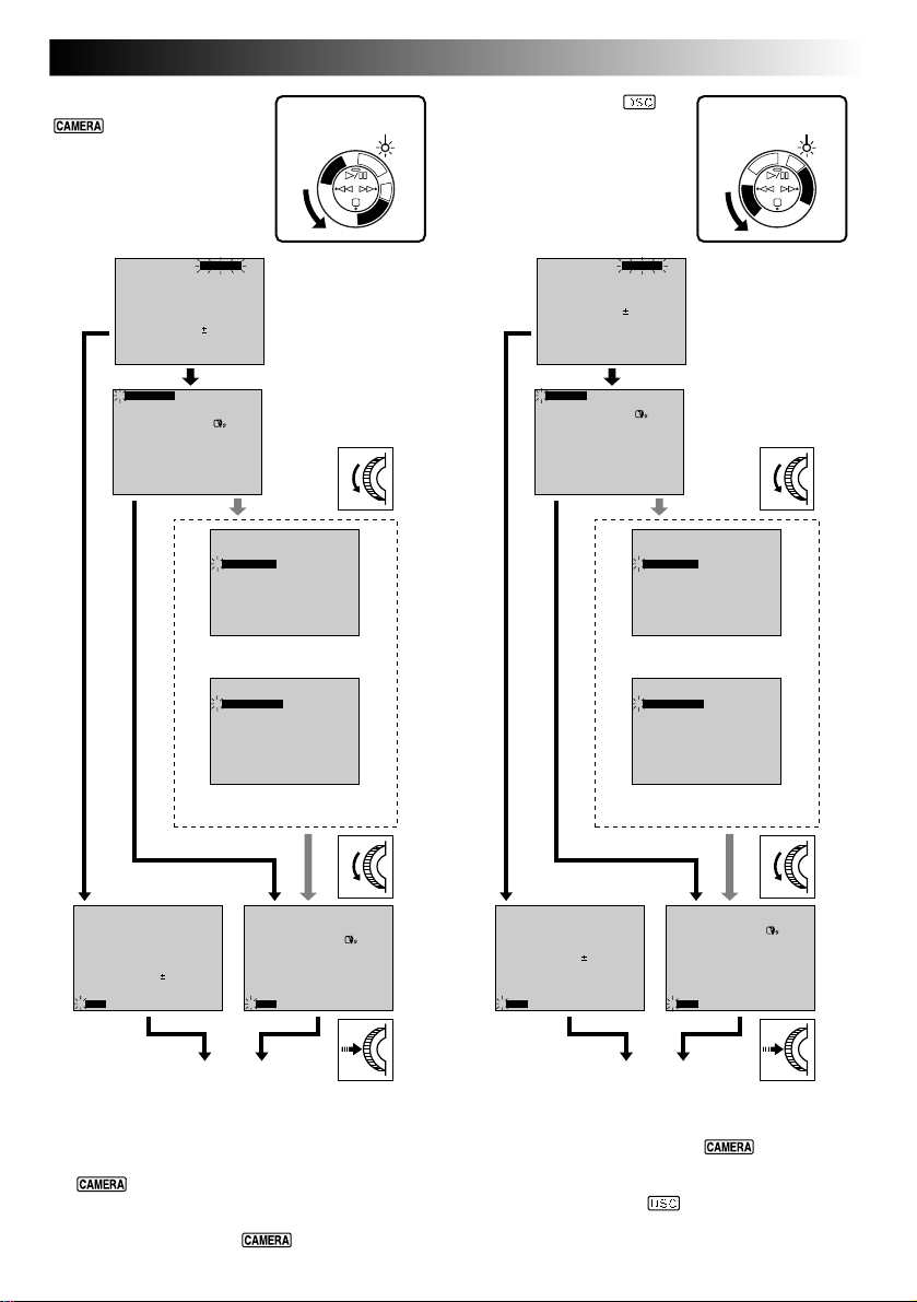
[Power Switch:
or 5S]
Display
4
FOCUS
EXPOSURE AUTO
W. BALANCE
FADER
/ WIPE
P. AE
/ EFFECT
FLASH ADJ.
TO MODE MENU
END
MANUAL
AUTO
OFF
OFF
0
[Power Switch: ]
Power lamp Power lamp
F
C
F
A
O
M
E
C
R
P
/
A
Y
5
A
S
L
P
D
S
C
D
S
C
P
L
A
Y
Display
Recording Menu
4
FOCUS
EXPOSURE AUTO
W. BALANCE
P. AE
/ EFFECT
FLASH ADJ.
TO MODE MENU
END
MANUAL
AUTO
OFF
0
Recording Menu
EN35
5
S
A
R
D
E
S
M
C
A
C
F
F
O
C
P
/
Y
A
L
P
D
S
C
P
L
A
Y
4
REC MODE
WIDE MODE OFF
ZOOM
DIS
GAIN UP
SELF-TIMER
FLASH
TO DATE / TIME MENU
TO SYSTEM MENU
END
FOCUS
EXPOSURE AUTO
W. BALANCE
FADER
/ WIPE
P. AE
/ EFFECT
FLASH ADJ.
TO MODE MENU
4
END
SP
40X
ON
AGC
OFF
AUTO
– – – – –6– – – – –
MANUAL
AUTO
OFF
OFF
0
Mode Menu
DATE/TIME
INDICATION ON
4
ON SCREEN OFF
DATE / TIME
RETURN
Date/Time Menu
SYSTEM MENU
4
TELE MACRO
SCENE
BEEP / TALLY
WIND CUT
SOUND MODE
ID NUMBER
REC SELECT
RETURN
System Menu
REC MODE
WIDE MODE OFF
ZOOM
DIS
GAIN UP
SELF-TIMER
FLASH
TO DATE / TIME MENU
TO SYSTEM MENU
4
END
ONDISPLAY
25 . 12 . 99
16 : 40
OFF
5S
ON
OFF
32kHz
06
TAPE
OFFDEMO. MODE
SP
40X
ON
AGC
OFF
AUTO
DEC 25 ’ 98
– – – – –6– – – – –
4
QUALITY FINE
DIS
GAIN UP
SELF-TIMER
FLASH
TO DATE / TIME MENU
TO SYSTEM MENU
END
40XZOOM
ON
AGC
OFF
AUTO
– – – – –6– – – – –
INDICATION ON
4
ON SCREEN OFF
DATE / TIME
RETURN
Mode Menu
DATE/TIME
ONDISPLAY
25 . 12 . 99
16 : 40
Date/Time Menu
SYSTEM MENU
4
TELE MACRO
BEEP / TALLY
ID NUMBER
DEMO. MODE
RETURN
OFF
ON
06
OFF
System Menu
FOCUS
EXPOSURE AUTO
W. BALANCE
P. AE
/ EFFECT
FLASH ADJ.
TO MODE MENU
: 30
4
END
MANUAL
AUTO
OFF
0
QUALITY FINE
DIS
GAIN UP
SELF-TIMER
FLASH
TO DATE / TIME MENU
TO SYSTEM MENU
– – – – –6– – – – –
4
END
40XZOOM
ON
AGC
OFF
AUTO
DEC 25 ’ 98
: 30
Normal Screen
Normal Screen
NOTES:
●
“FADER/WIPE” appears in the Recording Menu only when the Power Switch is set to “ ” or “5S”.
●
“REC MODE” and “WIDE MODE” appear in the Mode Menu only when the Power Switch is set to
“ ” or “5S”.
●
“QUALITY” appears in the Mode Menu only when the Power Switch is set to “ ”.
●
“SCENE”, “WIND CUT”, “SOUND MODE” and “REC SELECT” appear in the System Menu only when the
Power Switch is set to “ ” or “5S”.
Page 36

36 EN
RECORDING
Recording Menu Explanations
Advanced Features For Video And D.S.C. (cont.)
FOCUS
EXPOSURE
W.BALANCE
FADER/WIPE
P.AE/EFFECT
FLASH ADJ.
TO MODE MENU
Refer to “Focusing” (Z pg. 46, 47).
Refer to “Exposure Control” and “Iris Lock” (Z pg. 48, 49).
Refer to “White Balance Adjustment” and “Manual White Balance Operation”
(Z pg. 50, 51).
Refer to “Fade/Wipe Effects” (Z pg. 41 – 43).
Refer to “Program AE With Special Effects” (Z pg. 44, 45).
Refer to “Flash Brightness Adjustment” (Z pg. 33).
Refer to “Mode Menu Explanations”. (Z pg. 37).
Page 37
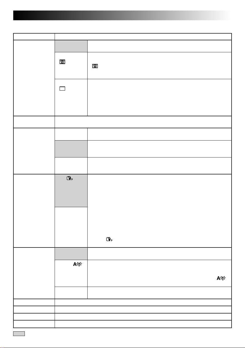
Mode Menu Explanations
REC MODE
WIDE MODE
QUALITY
ZOOM
DIS
GAIN UP
SELF-TIMER
FLASH
TO DA TE/TIME MENU
TO SYSTEM MENU
: Factory-preset
Allows you to set the recording mode (SP or LP) depending on your preference (Z pg. 13).
OFF
SQUEEZE
CINEMA
Allows you to set the Picture Quality mode (FINE, STANDARD or ECONOMY)
depending on your preference (Z pg. 15).
10X
40X
200X
ON
OFF
AGC
AUTO
OFF
Refer to “Self-Timer” (Z pg. 29).
Refer to “Snapshot Flash (Auto Flash)” (Z pg. 32).
Refer to “Date/Time Menu Explanations” (Z pg. 38).
Refer to “System Menu Explanations” (Z pg. 39).
EN37
Select “OFF” when you want to use neither “SQUEEZE” nor
“CINEMA”.
For playback on TVs with an aspect ratio of 16:9. Naturally expands
the image to fit the screen without distortion.
appears. When using this mode, refer to your wide-screen TV's
instruction manual. During playback/recording on 4:3 TVs/LCD
monitor/viewfinder, the image is elongated vertically.
Inserts black bands at the top and bottom of the screen. During
playback on wide-screen TVs, the black bands at the top and bottom
of the screen are cut and the screen ratio becomes 16:9. When using
this mode, refer to your wide-screen TV's instruction manual. During
playback/recording on 4:3 TVs/LCD monitor/viewfinder, black bands
are inserted at the top and bottom of the screen and the image
appears like a letterboxed 16:9 movie.
When set to “10X” while using digital zoom, the zoom magnification
will reset to 10X since digital zoom will be disengaged.
Allows you to use the Digital Zoom. By digitally processing and
magnifying images, zooming is possible from 10 times (the optical
zoom limit), to a maximum of 40 times digital magnification.
Allows you to use the Digital Zoom. By digitally processing and
magnifying images, zooming is possible from 10 times (the optical
zoom limit), to a maximum of 200 times digital magnification.
To compensate for unstable images caused by camera-shake,
particularly at high magnification.
NOTES:
●
Accurate stabilisation may not be possible if hand shake is
excessive, or under the following conditions:
•
When shooting subjects with vertical or horizontal stripes.
•
When shooting dark or dim subjects.
•
When shooting subjects with excessive backlighting.
•
When shooting scenes with movement in various directions.
•
When shooting scenes with low-contrast backgrounds.
●
Switch off the Digital Image Stabilizer (DIS) when recording with
the camcorder on a tripod.
●
The “ ” indicator appears blinking if the Stabilizer cannot be
used.
This is automatically activated during Full Auto mode. The overall
appearance may be grainy, but the image is bright.
The shutter speed is automatically adjusted (1/25 — 1/200 sec.).
Shooting a subject in low or poor lighting at 1/25 sec. shutter speed
provides a brighter image than in the AGC mode, but the subject’s
movements are not smooth or natural. When set to this mode, “ ”
is displayed.
Allows you to shoot dark scenes with no picture brightness adjustment.
CONTINUED ON NEXT PAGE
Page 38

38 EN
RECORDING
Date/Time Menu Explanations
INDICATION
ON SCREEN
DISPLAY
DATE/TIME
: Factory-preset
ON
OFF
OFF
ON
ON
OFF
Allows you to set the current date and time (Z pg. 11).
Advanced Features For Video And D.S.C. (cont.)
Makes all the indications appear in the camcorder (Z pg. 27).
Keeps all the indications (except the tape running indicator, warnings, etc.)
from appearing in the camcorder (Z pg. 27).
Keeps the camcorder’s display from appearing on the connected TV screen.
Makes the camcorder’s display appear on screen when the camcorder is
connected to a TV.
Makes the date/time settings appear in the camcorder (Z pg. 26).
Keeps the date/time settings from appearing in the camcorder.
Page 39
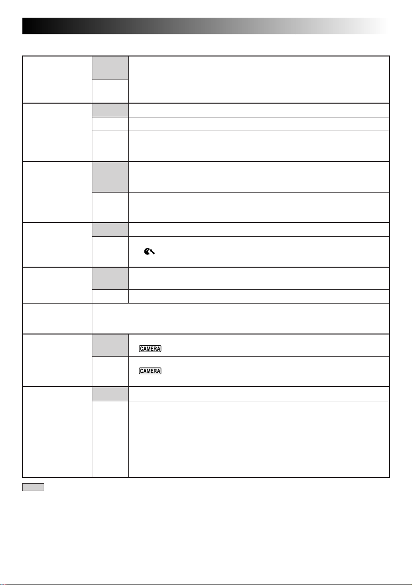
System Menu Explanations
TELE MACRO
SCENE
BEEP/TALLY
WIND CUT
SOUND MODE
ID NUMBER
REC SELECT
DEMO. MODE
OFF
ON
5S
5SD
ANIM.
ON
OFF
OFF
ON
32 kHz
48 kHz
This number is necessary when connecting the camcorder to a device such as a
computer using the J terminal (JLIP). The numbers range from 01 to 99. Factory setting
is 06.
TAPE
TAPE
&
CARD
OFF
ON
EN39
Usually the distance to a subject where the lens is in focus depends on the
zoom magnification. Unless there is a distance more than 1m to the subject,
the lens is out of focus at the maximum telephoto setting. When set to “ON”,
you can shoot a subject as large as possible at a distance of approx. 60 cm.
•Depending on the zoom position, the lens may go out of focus.
Z pg. 28.
Z pg. 28.
Allows you to record a 1/3-second clip. By using an inanimate object and
changing its position between shots, you can record the subject as though it
is moving (Z pg. 28).
The tally lamp comes on to signal the start of recording.
The beep sounds when the power is turned on or off, and at the beginning and
end of recording. Also to activate the shutter sound effect (Z pg. 23, 31).
The tally lamp remains off at all times.
Even though not heard while shooting, shutter sound is recorded on the
tape.
Disengages the function which cuts down on noise created by wind.
Helps cut down on noise created by wind.
•“ ” appears.
•The quality of the sound will change. This is normal.
Enables recording of stereo sound on four separate channels, and is
recommended for use when performing audio dubbing.
Enables recording of stereo sound on two separate channels.
When Snapshot recording is performed with the Power Switch set to
“ ” or “5S”, still images are recorded only onto the tape.
When Snapshot recording is performed with the Power Switch set to
“ ” or “5S”, still images are recorded not only onto the tape but also
in the MultiMediaCard.
Automatic demonstration will not take place.
Demonstrates certain functions such as Program AE with special effects,
etc., and can be used to confirm how these functions operate. When
“DEMO. MODE” is set to “ON” and the Recording Menu is closed,
demonstration starts.
NOTES:
●
If a tape is in the camcorder, the demonstration cannot be turned on.
●
By turning off the camcorder, “DEMO. MODE” is set to “OFF” automatically.
: Factory-preset
Page 40
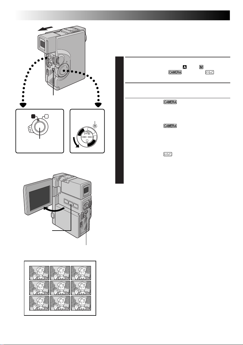
40 EN
START/STOP Button
Operation Switch Power Switch
MULTI SCREEN
Button
RECORDING
Lock Button
A M
PHOTO (SNAPSHOT) Button
Advanced Features For Video And D.S.C. (cont.)
Multi Screen Mode
The screen is divided into 9 quadrangles, with the scene
you are aiming at appearing in each one. This 9-quadrangle image can be recorded onto a tape or into a
MultiMediaCard.
SELECT OPERATION MODE
1
Set the Operation Switch to “ ” or “ ”. Then, set
the Power Switch to “ ”, “5S” or “ ” while
pressing down the Lock Button.
ACTIVATE MULTI SCREEN
2
Press MULTI SCREEN.
[Power Switch: “ ”]
If you press MULTI SCREEN during recording . . .
.... the screen will be divided into 9 quadrangles and
Power lamp
F
C
F
A
O
M
E
C
R
P
/
A
Y
5
A
S
L
P
D
C
D
S
C
P
L
A
Y
S
To Return To The Normal Screen . . .
NOTES:
●
●
●
they will be recorded onto a tape.
[Power Switch: “ ” or “5S”]
If you press MULTI SCREEN during Record-Standby . . .
.... the screen will be divided into 9 quadrangles.
Press START/STOP to start recording with 9
quadrangles.
[Power Switch: “ ”]
If you press MULTI SCREEN during RecordStandby. . .
.... the screen will be divided into 9 quadrangles.
Press PHOTO (SNAPSHOT) to record with 9
quadrangles.
.... press MULTI SCREEN again.
In the Multi Screen mode, it is not possible to bring up
the Menu Screen.
During Digital Zoom, the Multi Screen mode is not
available.
The Multi Screen mode is available during video
playback as well.
Multi Screen mode
Page 41
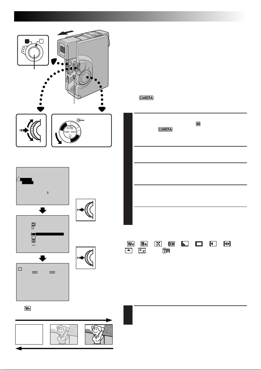
Operation Switch
EN41
Fade/Wipe Effects
A M
START/STOP
Button
MENU/SET Dial
Display
FOCUS
EXPOSURE AUTO
W. BALANCE
4
FADER
/ WIPE
P. AE
/ EFFECT
FLASH ADJ.
TO MODE MENU
END
FADER / WIPE
P
?
R
W
H
4
SEL.
B
K
B W
MANUAL
W
H
PAUSE
[Ex.:
FADER – WHITE]
Fade-in
AUTO
AUTO
OFF
OFF
0
WIPE– SHUTTER
RANDOM
OFF
FADER– WHITE
FADER– BLACK
FADER–MOSAIC
FADER– B.W
Lock Button
F
C
F
A
O
M
E
C
R
P
/
A
Y
5
A
S
L
P
D
S
C
D
S
C
P
L
A
Y
Power Switch
Recording Menu
FADER/WIPE Menu
Power lamp
IMPORTANT:
If certain modes of Programme AE with special effects
(Z pg. 44) are activated, some Fade/Wipe Effects cannot
be used. If you select a Fade/Wipe Effect that is unusable
in the current situation, the indication blinks.
These effects let you make pro-style scene transitions. Use
these to spice up the transition from one scene to the next.
You can also vary transitions from scene to scene.
This function is available only when the Power Switch is
set to “ ”.
EFFECT SELECTION
SELECT OPERATION MODE
1
Set the Operation Switch to “ ”. Then set the Power
Switch to “ ” while pressing down the Lock
Button. Pull out the viewfinder fully or open the LCD
monitor fully.
ACCESS RECORDING MENU
2
Press MENU/SET. The Recording Menu appears.
ACCESS “FADER/WIPE” MENU
3
Rotate MENU/SET to move the highlight bar to
“FADER/WIPE”, then press it.
SELECT EFFECT
4
Rotate MENU/SET to move the highlight bar to the
desired function, then press it.
•The FADER/WIPE Menu disappears and the effect is
reserved. The indicator representing the selected
effect appears.
FADE/WIPE SELECTION
( , , , , , , , ,
, and )
A scene gradually appears on a black, white, or black-andwhite screen (Fade-in or Wipe-in); or disappears, leaving a
black, white, or black-and-white screen (Fade-out or
Wipe-out).
Fade or Wipe works when recording is started or when
you stop recording.
Before the following step, perform the above steps 1
through 4.
START OR END RECORDING
5
Press START/STOP to activate Fade-in/out or Wipe-in/
out.
NOTE:
Z
pg. 42.
Fade-out
Page 42

42 EN
Previous scene end
Wipe-in
RECORDING
START/STOP Button
[Ex.:
Within 5 minutes . . .
WIPE – SCROLL]
Advanced Features For Video And D.S.C. (cont.)
PICTURE WIPE OR DISSOLVE SELECTION
( , , , , , and
)
Combine the Picture Wipe and Dissolve functions for a
professional transition effect. There are 6 Picture Wipe
effects and 1 Dissolve effect. The Picture Wipe or Dissolve
works when recording is started.
Before the following steps, perform steps 1 through 4 on
pg. 41.
STORE SCENE IN MEMORY
5
Engage the Record-Standby mode.
If you select Picture Wipe/Dissolve during
recording . . .
.... press START/STOP when one scene is finished.
The point at which the scene ended is stored in
memory.
If you select Picture Wipe/Dissolve during RecordStandby mode . . .
.... press START/STOP to start recording and press it
again when one scene is finished. The point at
which the scene ended is stored in memory.
If you select Picture Wipe/Dissolve during RecordStandby mode after performing a Picture Wipe/
Dissolve . . .
.... the point at which the scene ended is already
stored in memory.
START RECORDING
6
If you start recording a new scene within 5 minutes of
the end of the previous recording (without having
turned the camcorder’s power off), the previous scene
wipes out, revealing the new scene.
NOTES:
●
You can extend the length of a Fade or Wipe by pressing
and holding START/STOP .
●
If the power is turned off after a scene is finished
recording, the stored point is erased.
This disables the Picture Wipe/Dissolve combination.
When this happens, the Picture Wipe/Dissolve indicator
blinks. Try recording again, but do not turn the power off
when you are finished. Please be advised that power
also shuts off automatically if 5 minutes elapse in the
Record-Standby mode.
●
The sound at the end of the last recorded scene is not
stored.
Page 43

Fader And Wipe Menu
Menu Effect
EN43
FADER — WHITE
FADER — BLACK
FADER — MOSAIC
FADER — B.W
WIPE — CORNER
WIPE — WINDOW
WIPE — SLIDE
WIPE — DOOR
WIPE — SCROLL
WIPE — SHUTTER
DISSOLVE
Fade in or out with a white screen.
Fade in or out with a black screen.
Fade in or out with a full-screen mosaic effect.
Fade in to a colour screen from a black and white screen, or fade out
from colour to black and white.
Wipe in on a black screen from the upper right to the lower left corner,
or wipe out from lower left to upper right, leaving a black screen.
The scene starts in the centre of a black screen and wipes in toward
the corners, or comes in from the corners, gradually wiping out to the
centre.
Wipe in from right to left, or wipe out from left to right.
Wipe in as the two halves of a black screen open to the left and right,
revealing the scene, or wipe out and the black screen reappears from
left and right to cover the scene.
The scene wipes in from the bottom to the top of a black screen, or
wipes out from top to bottom, leaving a black screen.
Wipe in toward the centre of a black screen from the top and bottom,
or wipe out from the centre toward the top and bottom, leaving a
black screen.
The new scene gradually appears as the old one gradually disappears.
WIPE — CORNER
WIPE — WINDOW
WIPE — SLIDE
WIPE — DOOR
WIPE — SCROLL
WIPE — SHUTTER
RANDOM
The new scene wipes in over the previous one from the upper right
corner to the lower left corner.
The next scene gradually wipes in from the centre of the screen
toward the corners, covering the previous scene.
The next scene gradually wipes in over the previous one from right to
left.
The previous scene wipes out from the centre to the right and left, like
a door being pushed open to reveal the next scene.
The new scene wipes in over the last one from the bottom of the
screen to the top.
The new scene wipes in over the previous one from the centre toward
the top and bottom of the screen.
When this function is activated, the camcorder randomly selects the
effect used in scene transition (from , , , , , ,
, and ). The Picture Wipe/Dissolve function is not available.
Page 44

44 EN
OFF
4
FLASH ADJ
P. AE
/ EFFECT
END
TO MODE MENU
0
Operation Switch
RECORDING
Advanced Features For Video And D.S.C. (cont.)
Programme AE With Special Effects
A M
Lock Button
Power lamp
F
C
F
A
O
M
E
C
R
P
/
A
Y
5
A
S
L
P
D
S
C
D
S
C
P
L
A
Y
MENU/SET Dial Power Switch
Display
Recording Menu
P. AE / EFFECT
B/W
4
SEL.
1
2
TWILIGHT
SEPIA
MONOTONE
CLASSIC FILM
STROBE
SLOW 4X
SLOW 10X
P.AE/EFFECT Menu
IMPORTANT:
If certain Fades or Wipes (Z pg. 43) are activated, some
modes of Programme AE with special effects cannot be
used. If you select a mode that is unusable in the current
situation, the mode's symbol blinks.
You can choose any one of the effects from the P.AE/
EFFECT Menu.
SELECT OPERATION MODE
1
Set the Operation Switch to “ ”. Then set the Power
Switch to “ ” or “ ” while pressing down
the Lock Button. Pull out the viewfinder fully or open
the LCD monitor fully.
ACCESS RECORDING MENU
2
Press MENU/SET. The Recording Menu appears.
ACCESS “P.AE/EFFECT” SELECT MENU
3
Rotate MENU/SET to move the highlight bar to “P.AE/
EFFECT”, then press it.
SELECT MODE
4
Move the highlight bar to the desired mode by
rotating MENU/SET, then press it.
•The P.AE/EFFECT Menu disappears and the selected
mode is activated. The symbol of the selected mode
appears.
DISABLE MODE
5
To turn off the selected mode, re-access the P.AE/
EFFECT Menu and move the highlight bar to “OFF”
by rotating MENU/SET. Then press it.
NOTES:
●
Programme AE with special effects can be changed
during recording or during Record-Standby.
●
The following modes are available only when the Power
Switch is set to “ ”: “CLASSIC FILM”, “STROBE”
and “VIDEO ECHO”.
PAUSE
The indicator for the selected mode appears, and the
selected mode is engaged.
Page 45

SHUTTER
(Variable Shutter
Speed)
EN45
CLASSIC FILM*
1/50–The shutter speed is fixed at 1/50th of a
second. Black bands that usually appear when
shooting a TV screen become narrower.
1/100–The shutter speed is fixed at 1/100th of a
second. The flickering that occurs when shooting
under a fluorescent light or mercury-vapour lamp
is reduced.
1/250, 1/500–These settings allow fast-moving
images to be captured one frame at a time, for
vivid, stable slow-motion playback. The faster the
shutter speed, the darker the picture becomes. Use
the shutter function under good lighting conditions.
TWILIGHT
Makes evening scenes look more natural.
White Balance (Z pg. 50) is initially set to ,
but can be changed to your desired setting. When
Twilight is chosen, the camcorder automatically
adjusts the focus from approx. 10 m to infinity.
From less than 10 m, adjust the focus manually.
SEPIA
Recorded scenes have a brownish tint like old
photos. Combine this with the Cinema mode for a
classic look.
MONOTONE
Like classic black and white films, your footage is
shot in B/W. Used together with the Cinema mode,
it enhances the “classic film” effect.
Gives recorded scenes a strobe effect.
Your recording looks like a series of consecutive
snapshots.
STROBE*
SLOW (Slow Shutter)
You can light dark subjects or areas even brighter
than they would be under good natural lighting.
SLOW 4X
The Shutter Speed is set to 1/12.5th of a second to
quadruple the sensitivity.
SLOW 10X
The Shutter Speed is set to 1/5th of a second to
provide 10 times the sensitivity.
NOTES:
●
When using “SLOW”, the image takes on a
strobe-like effect.
●
Use “SLOW” only in dark areas.
●
The Manual Focus indication may appear and
flash when “SLOW” is in use.
●
If the image is out of focus, adjust manually. It is
also recommended that you use a tripod, if
possible.
VIDEO ECHO*
*Available only when the Power Switch is set to “ ”.
Adds a “ghost” to the subject, giving your
recording a “fantasy” feeling.
Page 46

46 EN
RECORDING
Focus detection zone
Advanced Features For Video And D.S.C. (cont.)
Focusing
AUTO FOCUS
The camcorder’s Full Range AF system offers continuous
shooting ability from close-up (as close as approx. 5 cm to
the subject) to infinity. However, correct focus may not be
obtainable in the situations listed below (in these cases use
manual focusing):
•When two subjects overlap in the same scene.
•When illumination is low.*
•When the subject has no contrast (difference in brightness and darkness), such as a flat, one-colour wall, or a
clear, blue sky.*
•When a dark object is barely visible in the viewfinder.*
•When the scene contains minute patterns or identical
patterns that are regularly repeated.
•When the scene is affected by sunbeams or light
reflecting off the surface of a body of water.
•When shooting a scene with a high-contrast
background.
* The following low-contrast warnings appear blinking:
, , and
NOTES:
●
If the lens is smeared or blurred, accurate focusing is not
possible. Keep the lens clean, wiping with a piece of soft
cloth if it gets dirty. When condensation occurs, wipe
with a soft cloth or wait for it to dry naturally.
●
When shooting a subject close to the lens, zoom-out first
(Z pg. 24). If zoomed-in in the auto focus mode, the
camcorder could automatically zoom out depending on
the distance between the camcorder and the subject.
When “TELE MACRO” (Z pg. 39) is activated, the
camcorder will not zoom out automatically.
Page 47

FOCUS
EXPOSURE AUTO
AUTO
MANUAL
W. BALANCE
4
Operation Switch
A M
Lock Button
Power lamp
F
C
F
A
O
M
E
C
R
P
/
A
Y
5
A
S
L
P
D
S
C
D
S
C
P
L
A
Y
MENU/SET Dial Power Switch
EN47
MANUAL FOCUS
NOTE:
You should already have made the necessary viewfinder
adjustments (Z pg. 10). If you have not, do so before
continuing.
SELECT OPERATION MODE
1
Set the Operation Switch to “ ”. Then, set the
Power Switch to “ ”, “5S” or “ ” while
pressing down the Lock Button. Pull out the viewfinder fully or open the LCD monitor fully.
ACCESS RECORDING MENU
2
Press MENU/SET. The Recording Menu appears.
ACCESS “FOCUS”
3
Rotate MENU/SET to move the highlight bar to
“FOCUS”, then press it.
ACCESS MANUAL FOCUS
4
Rotate MENU/SET to display “MANUAL”, then press
it. The Recording Menu disappears and “FOCUS” is
displayed in the upper left corner. The focus is locked
at this point.
FOCUS
FOCUS
Display
Recording Menu
ADJUST FOCUS
5
To farther subject . . .
.... rotate MENU/SET upward. “ ” appears and
blinks. Go to step 6.
To nearer subject . . .
.... rotate MENU/SET downward. “ ” appears and
blinks. Go to step 6.
END ADJUSTMENT OF FOCUS
6
Press MENU/SET. Focus adjustment is complete. The
indication changes from “FOCUS” to “MANUAL”.
•If you want to reset the focus, repeat from step 2.
To Change To Auto Focus . . .
.... rotate MENU/SET to display “AUTO” then press it in
step 4. The manual focus indicators disappear. Or, set
the Operation Switch to “ ”.
NOTES:
●
After the Power Switch is set to “OFF”, Manual Focus is
reset to “AUTO”.
●
Be sure to focus the lens in the maximum telephoto
position when you use the Manual Focus mode. If you
focus in on a certain subject in the wide-angle position,
sharply focused images cannot be obtained when
zoomed up because the depth-of-field is reduced at
longer focal lengths.
●
When the focus level cannot be adjusted any farther or
closer, “ ” or “ ” will blink.
Page 48
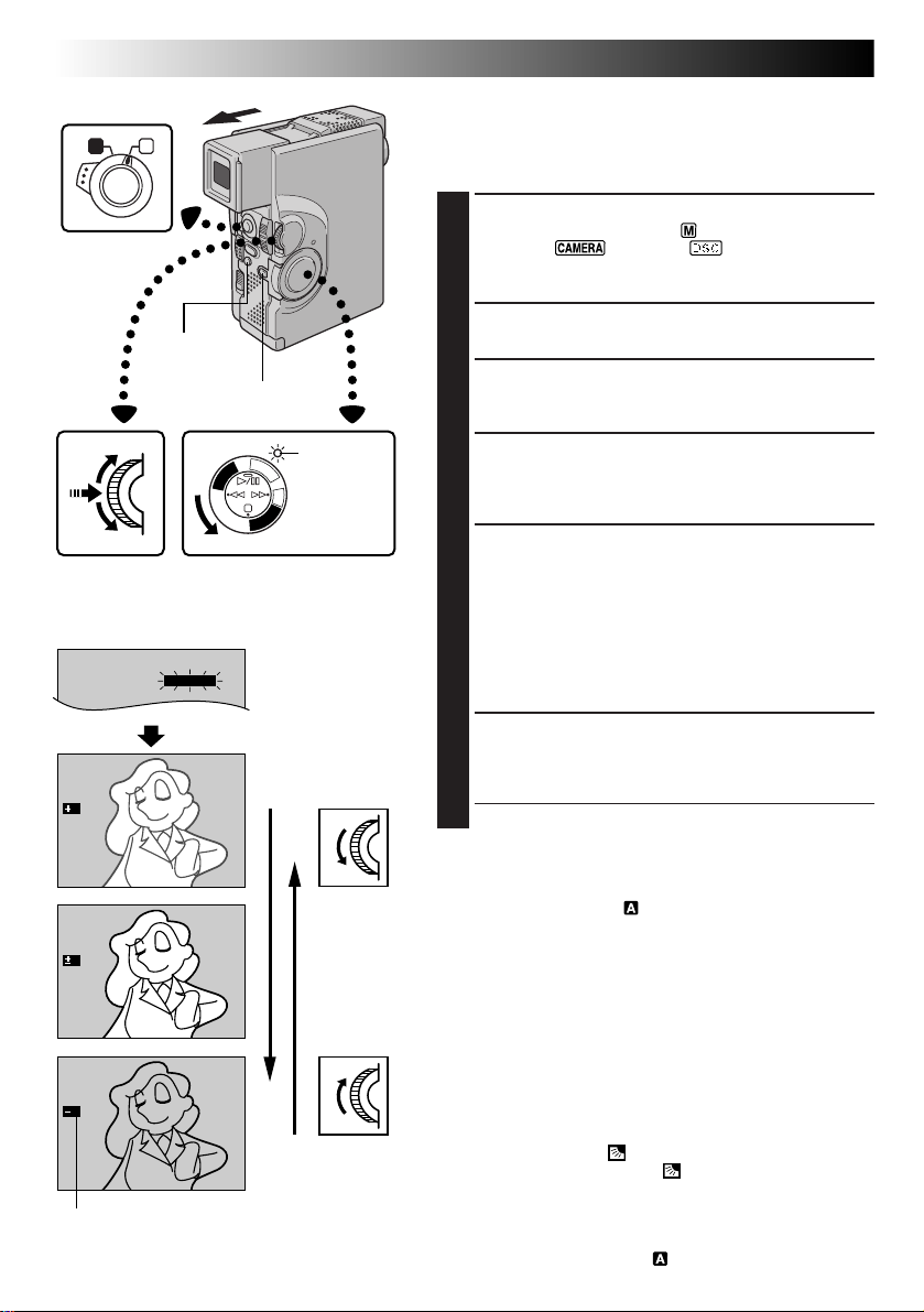
48 EN
FOCUS
EXPOSURE
MANUAL
AUTO
AUTO
W. BALANCE
4
Operation Switch
A M
MENU/SET Dial
EXP.
6
EXP.
0
EXP.
6
Exposure control indicator
RECORDING
BACK LIGHT
Button
Lock Button
C
P
/
Y
A
L
P
Display
Power lamp
F
C
F
A
O
M
E
R
A
5
S
D
S
C
D
S
C
P
L
A
Y
Power Switch
Recording Menu
To darken the image
To brighten the image
Advanced Features For Video And D.S.C. (cont.)
Exposure Control
This feature automatically adjusts the iris for the best
available picture quality, but you can override and make
the adjustment manually.
SELECT OPERATION MODE
1
Set the Operation Switch to “ ”. Then, set the Power
Switch to “ ”, “5S” or “ ” while pressing
down the Lock Button. Pull out the viewfinder fully or
open the LCD monitor fully.
ACCESS RECORDING MENU
2
Press MENU/SET. The Recording Menu appears.
ACCESS “EXPOSURE”
3
Rotate MENU/SET to move the highlight bar to
“EXPOSURE”, then press it.
ACCESS EXPOSURE CONTROL
4
Rotate MENU/SET to display “MANUAL”, then press it.
The Recording Menu disappears. “EXP.” and the highlight
bar on the exposure control indicator are displayed.
ADJUST EXPOSURE
5
To brighten the image . . .
..... rotate MENU/SET upward. The exposure control
indicator increases (maximum +6).
Go to step 6.
To darken the image . . .
..... rotate MENU/SET downward. The exposure control
indicator decreases (maximum –6).
Go to step 6.
END ADJUSTMENT OF EXPOSURE
6
Press MENU/SET. Exposure adjustment is complete. The
indication “EXP.” changes to “MANUAL” and the highlight
bar on the exposure control indicator goes out.
•If you want to reset the exposure, repeat step 2.
To Return To Automatic Exposure Control . . .
..... rotate MENU/SET to display “AUTO” then press it in step
4. The exposure control indicator disappears. Or set the
Operation Switch to “ ”.
NOTES:
●
After the Power Switch is set to “OFF”, Exposure Control is
reset to “AUTO”.
●
Manual exposure adjustment is recommended in the
following situations:
•
When shooting using reverse lighting or when the
background is too bright.
•
When shooting on a reflective natural background such
as at the beach or when skiing.
•
When the background is overly dark or the subject light.
To Brighten The Subject Quickly . . .
..... press BACK LIGHT. is displayed and the subject is
brightened. If pressed again, disappears and the
brightness returns to the previous level. The value shown by
the exposure control indicator plus 2 is the back light
compensation level. The maximum compensation level is
+6. Back light compensation is also available when the
Operation Switch is set to “ ”.
Page 49
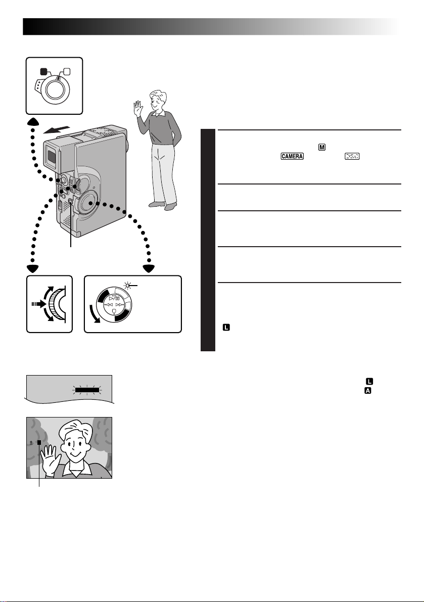
FOCUS
EXPOSURE
MANUAL
AUTO
AUTO
W. BALANCE
4
Operation Switch
A M
Lock Button
MENU/SET Dial
F
C
F
A
O
M
E
C
R
P
/
A
Y
A
L
P
S
C
P
L
A
Y
Power Switch
Power lamp
5
S
D
S
C
D
EN49
Iris Lock
Use this function when shooting a moving subject, when
zooming, when the subject changes its distance (thus its
size in the LCD monitor or the viewfinder), or when you
want to lock the brightness level.
When the subject is close, keep the iris locked. Even when
the subject moves away from you, the image will not
darken or brighten.
SELECT OPERATION MODE
1
Set the Operation Switch to “ ”. Then, set the
Power Switch to “ ”, “5S” or “ ” while
pressing down the Lock Button. Pull out the viewfinder fully or open the LCD monitor fully.
ACCESS RECORDING MENU
2
Press MENU/SET. The Recording Menu appears.
ACCESS “EXPOSURE”
3
Rotate MENU/SET to move the highlight bar to
“EXPOSURE”, then press it.
ACCESS EXPOSURE CONTROL
4
Rotate MENU/SET to display “MANUAL”, then press
it. “EXP.” is displayed.
CENTRE SUBJECT, LOCK IRIS
5
Adjust zoom so that the subject fills the LCD monitor
or the viewfinder, then press and hold MENU/SET for
over 2 seconds. The exposure control indicator and
“ ” appear, indicating that the iris is locked.
Press MENU/SET. The indication displayed in the
upper left corner changes from “EXP.” to “MANUAL”.
Display
EXP.
0 L
Iris lock indicator
Recording Menu
To Return To Automatic Iris Control . . .
.... rotate MENU/SET to display “AUTO” then press it in
step 4. The exposure control indicator and “ ”
disappear. Or, set the Operation Switch to “ ”.
NOTE:
Iris lock is recommended in the following situations:
●
When shooting on a reflective natural background such
as at the beach or when skiing.
●
When shooting objects under a spotlight.
●
When the subject is backing away.
●
When zooming.
To Lock The Exposure Control And The Iris . . .
.... after step 4, adjust the exposure rotating MENU/SET.
Then lock the iris in step 5. For automatic locking,
rotate MENU/SET to display “AUTO”, then press it in
step 4. The iris becomes automatic after about 2
seconds.
Iris
Works like the pupil of the human eye. In a well-lit
environment, the human pupil contracts to keep too much
light from entering. In low lighting, the pupil dilates to
allow more light in.
Page 50
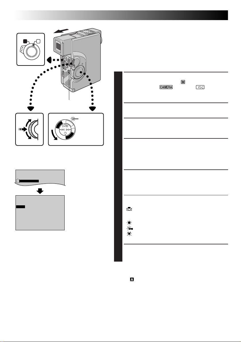
50 EN
FOCUS
EXPOSURE AUTO
AUTO
W. BALANCE
4
AUTO
Operation Switch
A M
W . BAL .
AUTO
RECORDING
Lock Button
C
P
/
Y
A
L
P
Display
Power lamp
F
C
F
A
O
M
E
R
A
5
S
D
S
C
D
S
C
P
L
A
Y
Power SwitchMENU/SET Dial
Recording Menu
White Balance
Adjustment
Advanced Features For Video And D.S.C. (cont.)
White Balance Adjustment
A term that refers to the correctness of colour reproduction
under various lighting. If the white balance is correct, all
other colours will be accurately reproduced.
The white balance is usually adjusted automatically.
However, the more advanced camcorder operator would
prefer to control this function manually and achieve a
more professional colour/tint reproduction.
SELECT OPERATION MODE
1
Set the Operation Switch to “ ”. Then, set the
Power Switch to “ ”, “5S” or “ ” while
pressing down the Lock Button. Pull out the viewfinder fully or open the LCD monitor fully.
ACCESS RECORDING MENU
2
Press MENU/SET. The Recording Menu appears.
ACCESS “W.BALANCE”
3
Rotate MENU/SET to move the highlight bar to
“W.BALANCE”, then press it.
ACCESS WHITE BALANCE ADJUST-
4
MENT
The Recording Menu disappears. “W.BAL.” appears
in the upper left corner and the currently selected
mode indication is also displayed.
SET FUNCTION PARAMETERS
5
Cycle through the available settings of the selected
functions by rotating MENU/SET, and stop when the
one you want is displayed.
“AUTO” – The white balance is adjusted automati-
“ ” – When shooting with the white balance
“ ” – When shooting outdoors on a sunny day.
“ ” – When shooting outdoors on a cloudy day.
“ ” – When using a video light or other similar
cally. This is the factory preset position.
already having been set on the subject
(Z pg. 51).
type of lighting.
CLOSE WHITE BALANCE ADJUSTMENT
6
Press MENU/SET again. Selection is complete. The
indication “W.BAL.” changes to “MANUAL”.
To Return To Automatic White Balance . . .
.... select “AUTO” in step 5. Or, set the Operation Switch
to “ ”.
NOTE:
White balance cannot be used when Sepia or Monotone
(Z pg. 45) is activated.
Page 51
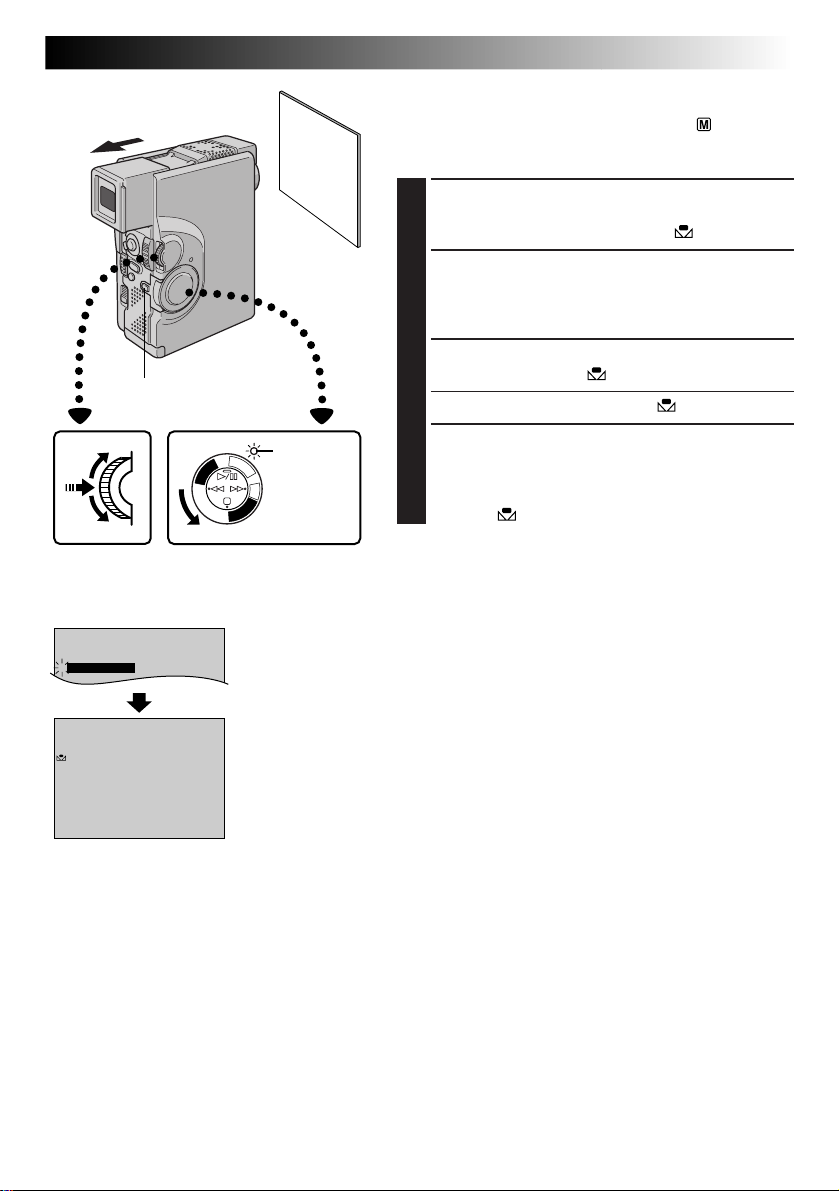
FOCUS
EXPOSURE AUTO
AUTO
W. BALANCE
4
AUTO
Lock Button
White paper
EN51
Manual White Balance Operation
If the camera is operating in Manual mode “ ”, perform
Manual White Balance when shooting under various types
of lighting.
SELECT OPERATION MODE
1
Follow steps 1 through 5 of the white balance
adjustment (Z pg. 50), and select “ MAN.”.
SET MANUAL WHITE BALANCE
2
Hold a sheet of plain white paper in front of the
subject. Adjust zoom or position yourself so that the
white paper fills the screen.
ENTER SETTING
3
Press MENU/SET until begins blinking.
•When the setting is completed, stops blinking.
MANUAL
Display
Power lamp
F
C
F
A
O
M
E
C
R
P
/
A
Y
5
A
S
L
P
D
S
C
D
S
C
P
L
A
Y
Power SwitchMENU/SET Dial
Recording Menu
Manual White
Balance Adjustment
EXIT MANUAL WHITE BALANCE
4
ADJUSTMENT
Press MENU/SET. The indication “W.BAL.” changes
to “MANUAL” and only the Manual White Balance
indicator is displayed.
To Change The Tint For Recording . . .
.... in step 2, substitute coloured paper for white. The
white balance is adjusted based on the colour,
changing the tint. Red paper — deeper green; blue
paper — orange; yellow paper — deeper purple.
NOTES:
●
In step 2, it may be difficult to focus on the white paper
in some circumstances. In such a case, adjust focus
manually (Z pg. 47).
●
A subject can be shot under various types of lighting
conditions indoors (natural, flourescent, candlelight,
etc.). Because the colour temperature is different
depending on the light source, the tint of the subject will
differ depending on the white balance settings. Use this
function for a more natural result.
●
Once you adjust white balance during Manual White
Balance operation, the setting is retained even if the
power is turned off or the battery removed.
Page 52
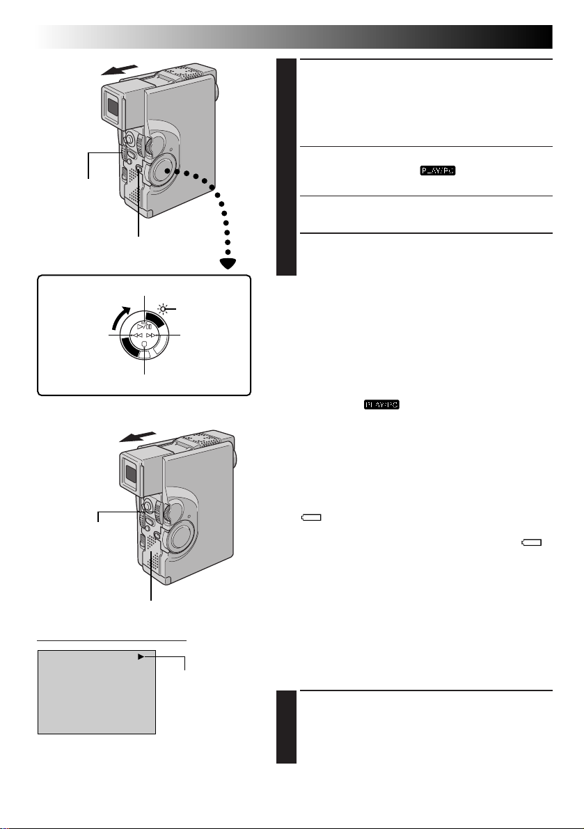
52 EN
OPEN/EJECT
Switch
Power Switch
Rewind (
Button
Power Zoom Lever
(VOL.)
Lock Button
Play/Pause (
2
)
Stop (5) Button
4
Y
A
L
P
C
S
D
Speaker
/6) Button
Power lamp
P
L
A
Y
/
P
C
O
F
F
C
A
M
E
R
A
5
S
D
S
C
Fast-Forward
3
) Button
(
PLAYBACK
LOAD A CASSETTE
1
Slide OPEN/EJECT in the direction of the arrow, then
swing the cassette cover open until it locks. The
holder opens automatically.
Insert a tape and press “PUSH HERE” to close the
cassette holder.
SELECT OPERATION MODE
2
Set the Power Switch to “ ” while pressing
down the Lock Button. The power lamp lights.
PLAY BACK
3
Press 4/6. The playback picture appears.
STOP PLAYBACK
4
Press 5.
Basic Playback For Video
Rewind or Fast-forward the tape
Press 2 to rewind, or 3 to fast-forward the tape during
Stop mode.
NOTES:
●
If Stop mode continues for 5 minutes when the power
supply is a battery pack, the camcorder shuts off
automatically. To turn on again, set the Power Switch to
“OFF”, then to “ ”.
●
The playback picture can also be viewed in the
viewfinder (with the viewfinder pulled out) or on a
connected TV (Z pg. 70, 71). Camcorder operation is
the same as described in this section.
●
You can also view the playback picture on the LCD
monitor with it flipped over and retracted.
●
LCD monitor/viewfinder indications:
•
When power is supplied from the battery pack: the
“ ” battery pack remaining power indicator is
displayed on the LCD monitor when it is turned on.
When power is supplied through the DC cord: “ ”
does not appear.
•
During Stop mode, none of the indications are
displayed in the viewfinder.
●
Copyguarded tapes cannot be played back. The screen
displays a blue background.
LCD monitor/Viewfinder Indication
Tape running
indicator
Speaker (or Headphones) Volume Control
You can adjust the speaker (or headphones connected to
the headphones connector) volume by pushing the Power
Zoom Lever.
ADJUST VOLUME
1
If you want to turn up the volume . . .
.... slide the Power Zoom Lever (VOL.) towards “+”.
If you want to turn down the volume . . .
.... slide the Power Zoom Lever (VOL.) towards “–”.
Page 53
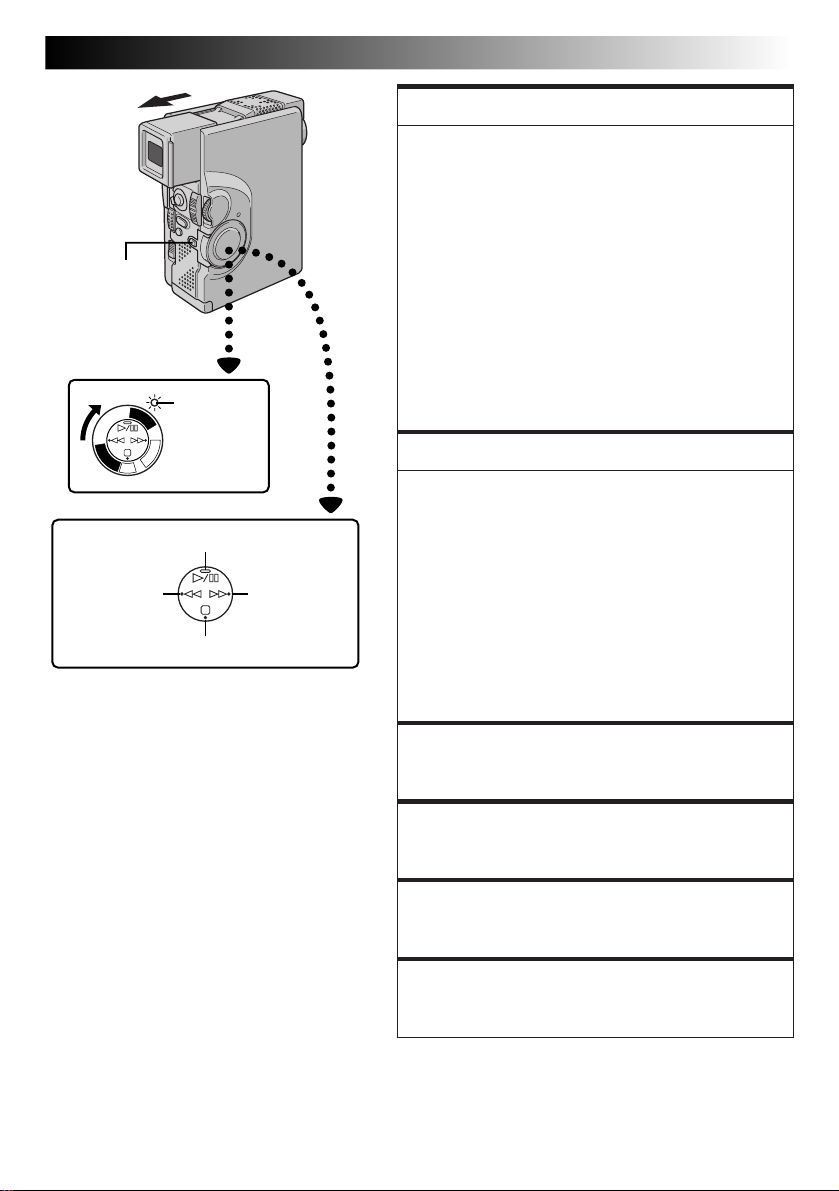
EN53
Lock Button
Power Switch
P
L
A
Y
A
L
P
C
S
D
D
S
C
Play/Pause (
2
Rewind (
Button
Power lamp
Y
/
P
C
O
F
F
C
A
M
E
R
A
5
S
)
Stop (5) Button
4
/6) Button
Fast-Forward
3
) Button
(
FEATURE:
Still Playback
PURPOSE:
To pause during playback.
OPERATION:
1) Press 4/6 during playback.
2) To resume normal playback, press 4/6 again.
NOTES:
●
If still playback continues for more than about 3
minutes, the camcorder’s Stop mode is automatically engaged. After 5 minutes in the Stop mode,
the camcorder’s power is automatically turned off.
●
When 4/6 is pressed, the image may not pause
immediately so that the camcorder can stabilise the
still image. During this time, if PAUSE
(6)
on the
remote control is pressed, Slow-Motion Playback
will start. This is not a malfunction.
FEATURE:
Shuttle Search
PURPOSE:
To allow high-speed search in either direction.
OPERATION:
1) Press 3 to forward or press 2 to reverse during
playback.
2) To resume normal playback, press 4/6.
NOTES:
●
During playback, press and hold 2 or 3. The
search continues as long as you hold the button.
Once you release it, normal playback resumes.
●
A slight mosaic effect appears on screen during
Shuttle Search. This is not a malfunction.
FEATURE:
Slow-Motion Playback
Available only with the RM-V713U remote control
(provided) (Z pg. 82).
FEATURE:
Frame-By-Frame Playback
Available only with the RM-V713U remote control
(provided) (Z pg. 82).
FEATURE:
Playback Zoom
Available only with the RM-V713U remote control
(provided) (Z pg. 82).
FEATURE:
Playback Special Effects
Available only with the RM-V713U remote control
(provided) (Z pg. 83).
Page 54
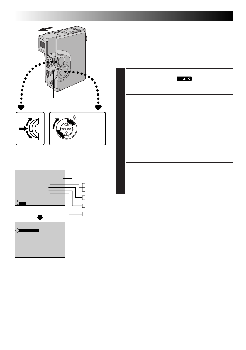
54 EN
PLAYBACK
Advanced Features For Video
Playback Menu
The Playback Menu allows you to set the following
functions:
Playback Sound (32 kHz, 48 kHz), Synchro Comp,
Indication, Display and Time Code.
procedure applies to all except
89).
SELECT OPERATION MODE
1
Set the Power Switch to “ ” while pressing
down the Lock Button. Pull out the viewfinder fully or
open the LCD monitor fully.
The following
Synchro Comp (Z pg. 88,
MENU/SET Dial
Display
32kHz MODE
SYNCHRO
INDICATION
DISPLAY
TIMECODE
4
END
Playback Menu
4
32kHz MODE
SYNCHRO
INDICATION
DISPLAY
TIMECODE
END
Lock Button
FULL SOUND48kHz MODE
SOUND1
0 . 0
ON
ON
OFF
FULL SOUND48kHz MODE
SOUND1
0 . 0
ON
ON
OFF
P
L
A
Y
/
P
C
O
F
F
A
Y
M
A
E
L
R
P
A
C
5
S
S
D
D
S
C
Power Switch
Power lamp
C
FULL SOUND
SOUND1
SOUND2
FULL SOUND
SOUND1
SOUND2
ON
OFF
ON
OFF
ON
OFF
ACCESS PLAYBACK MENU
2
Press MENU/SET. The Playback Menu appears.
SELECT FUNCTION
3
Move the highlight bar to the desired function by
rotating MENU/SET. Press it to activate.
SET FUNCTION PARAMETERS
4
Rotate MENU/SET to cycle through the available
settings for the selected function, and stop when the
desired setting appears. Then press MENU/SET, and
the highlight bar automatically moves to “END”.
•To set parameters for other functions, repeat steps 3
and 4.
CLOSE MENU
5
Press MENU/SET again, and the menu disappears.
Page 55
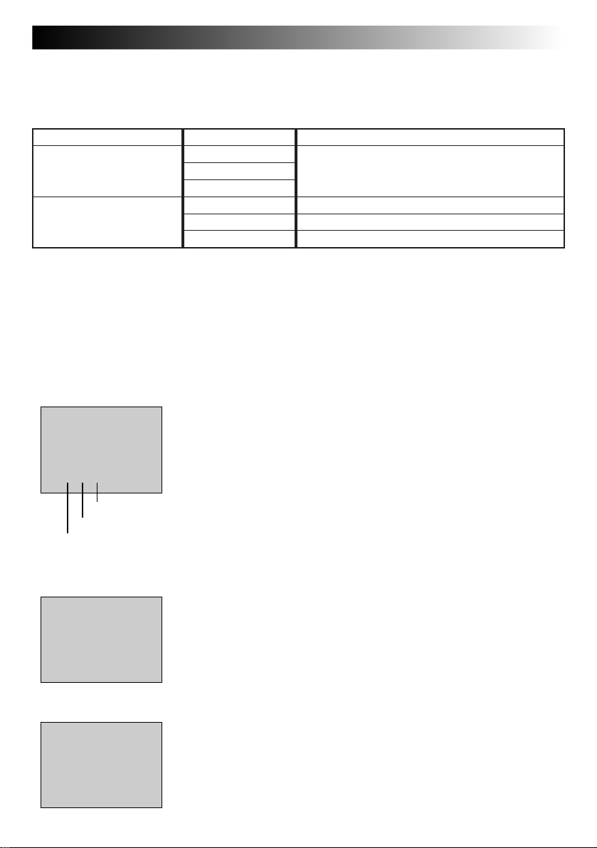
EN55
Playback Sound
During playback, the camcorder detects the sound mode in which the recording was made, and plays the
sound back. Select the type of sound to accompany your playback picture. (32 kHz is preset to “SOUND 1”
and 48 kHz is preset to “FULL SOUND”.)
Recording sound Display Output sound
FULL SOUND
32 kHz SOUND 1 Stereo sound
SOUND 2
FULL SOUND Stereo sound
48 kHz SOUND 1 “L” sound is output on both channels
SOUND 2 “R” sound is output on both channels
When watching a tape recorded at 32 kHz, if you want to change the output sound, access the Playback Menu
and, in step 3 on page 54, select “32 kHz MODE” and set it for “FULL SOUND”, “SOUND 1” or “SOUND 2”.
When playing back a tape recorded at 48 kHz, set in the same manner.
NOTES:
●
You can also use the provided RM-V713U remote control’s AUDIO MONITOR button to change the output sound
(without having to access the Playback Menu). Make sure you point the remote control at the camcorder ’s remote sensor.
●
During playback, the camcorder detects the sound mode in which the recording was made. This detection cannot
be made during fast-forward or rewind. During playback the sound mode is displayed in the upper left corner.
Display
Frames*
Seconds
DEC 25 ’ 98
PM 5 : 30
25 . 12 . 99
25 . 12 . 99
12 : 34 : 24
TC
Minutes
*25 frames = 1 second
12 : 34 : 24
TC
32kHz/SOUND1
12 : 34 : 24
TC
16 : 40
16 : 40
TIME CODE
(Displaying The Time Code During Playback)
You can display the Time Code on screen during playback. This is especially
useful for editing. This function is preset to “OFF”. To turn it on, select “TIME
CODE” at the Playback Menu and change the setting (Z pg. 54).
ON– The Time Code is displayed on the playback screen.
OFF– The Time Code does not appear.
DISPLAY (Displaying the Date During Playback)
If the time has been set, the date is automatically recorded separately from
the recorded video signal. You can display or remove the date anytime
during playback. This function is preset to “ON”. To turn it off, select
“DISPLAY” at the Playback Menu and change the setting (Z pg. 54).
ON– The date is displayed on the playback screen.
OFF– The date is not displayed.
INDICATION
You can make the Playback Sound, Time Code and Date indications
disappear. This function overrides the “TIME CODE” and “DISPLAY”
settings in the Playback Menu. The factory-preset is “ON”. To turn it off,
select “INDICATION” in the Playback Menu and change the setting
(Z pg. 54).
OFF– The Playback Sound, Time Code and Date indications do not appear
on the Playback Screen.
ON– The Playback Sound, Time Code and Date indications are displayed
according to how “TIME CODE” and “DISPLAY” are set in the
Playback Menu.
NOTE:
If “INDICATION” is set in the Date/Time Menu, “INDICATION” in the Playback
Menu will also be set to the same setting (Z pg. 34 – 38).
Page 56
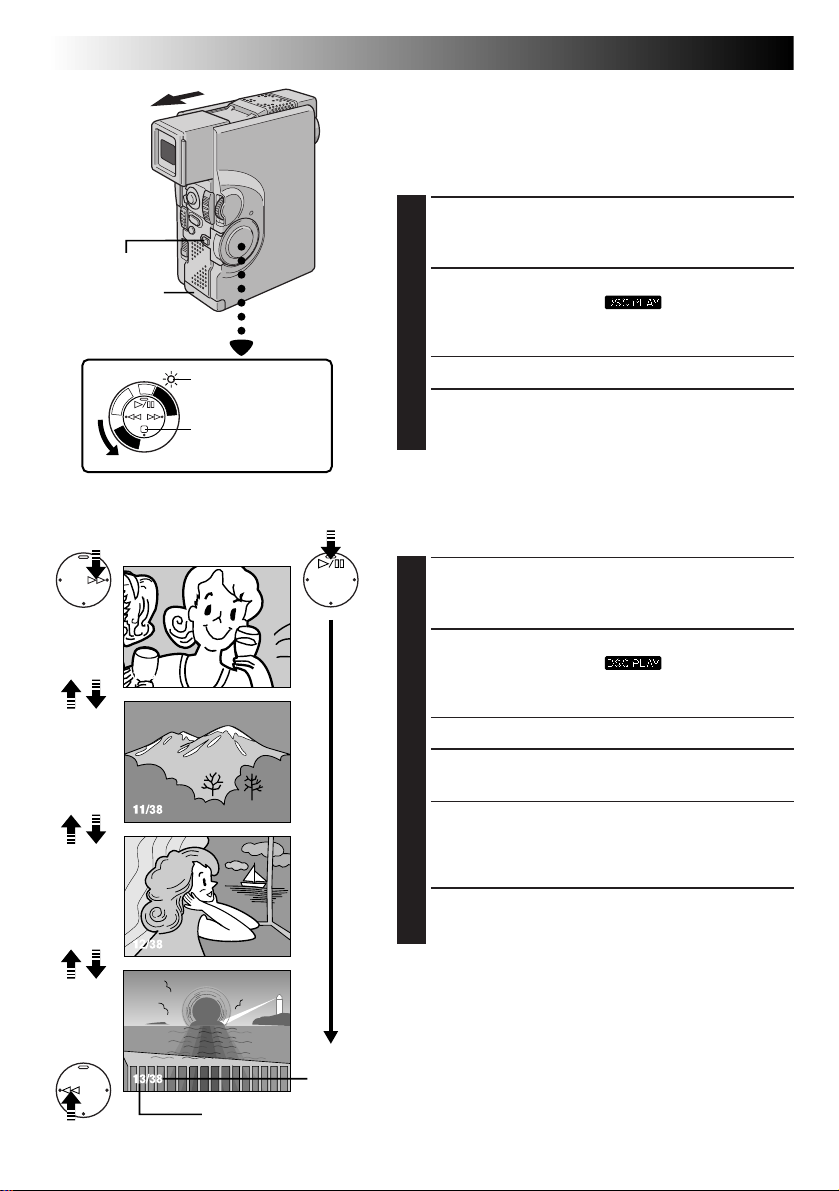
56 EN
Lock Button
Card cover
Power Switch
PLAYBACK
Basic Playback For D.S.C.
Normal Playback
Images shot with the camcorder are automatically
numbered, then stored in numerical order in the
MultiMediaCard. You can view the stored images, one at a
time, much like flipping through a photo album.
LOAD A MULTIMEDIACARD
1
Open the card cover. Insert a MultiMediaCard, then
close the card cover.
SELECT OPERATION MODE
2
Set the Power Switch to “ ” while pressing
down the Lock Button. Open the LCD monitor fully
or pull out the viewfinder fully.
Power lamp
S
C
D
S
D
5
S
A
C
R
P
E
L
M
A
A
Y
C
F
F
O
C
P
/
Y
A
L
P
Stop (5) Button
•A stored image is displayed.
DISPLAY ANOTHER IMAGE
3
Press 3 to display the next image.
Press 2 to display the previous image.
[For Normal Playback]
To display the next image
10/38
11/38
12/38
13/38
To display
the previous image
[For Auto Playback]
Display
Image number*
Displays the index number
of the image file.
Auto Playback
You can run through all the images stored in memory
automatically.
LOAD A MULTIMEDIACARD
1
Open the card cover. Insert a MultiMediaCard, then
close the card cover.
SELECT OPERATION MODE
2
Set the Power Switch to “ ” while pressing
down the Lock Button. Open the LCD monitor fully
or pull out the viewfinder fully.
•A stored image is displayed.
START AUTO PLAYBACK
3
Press 4/6.
•If you press 2 during Auto Playback, images are
displayed in descending order.
•If you press 3during Auto Playback, images are
displayed in ascending order.
STOP AUTO PLAYBACK
4
Press 5.
NOTE:
Even if you shoot a new image after playing back a lownumbered one, this will not overwrite an existing image,
because new images are automatically stored after the lastrecorded one.
Total number of images*
Displays the total number of stored images.
* Not displayed when “INDICATION” is set to “OFF” in the Date/
Time Menu (
Z pg. 38) or Video Playback Menu (Z pg. 55).
Page 57
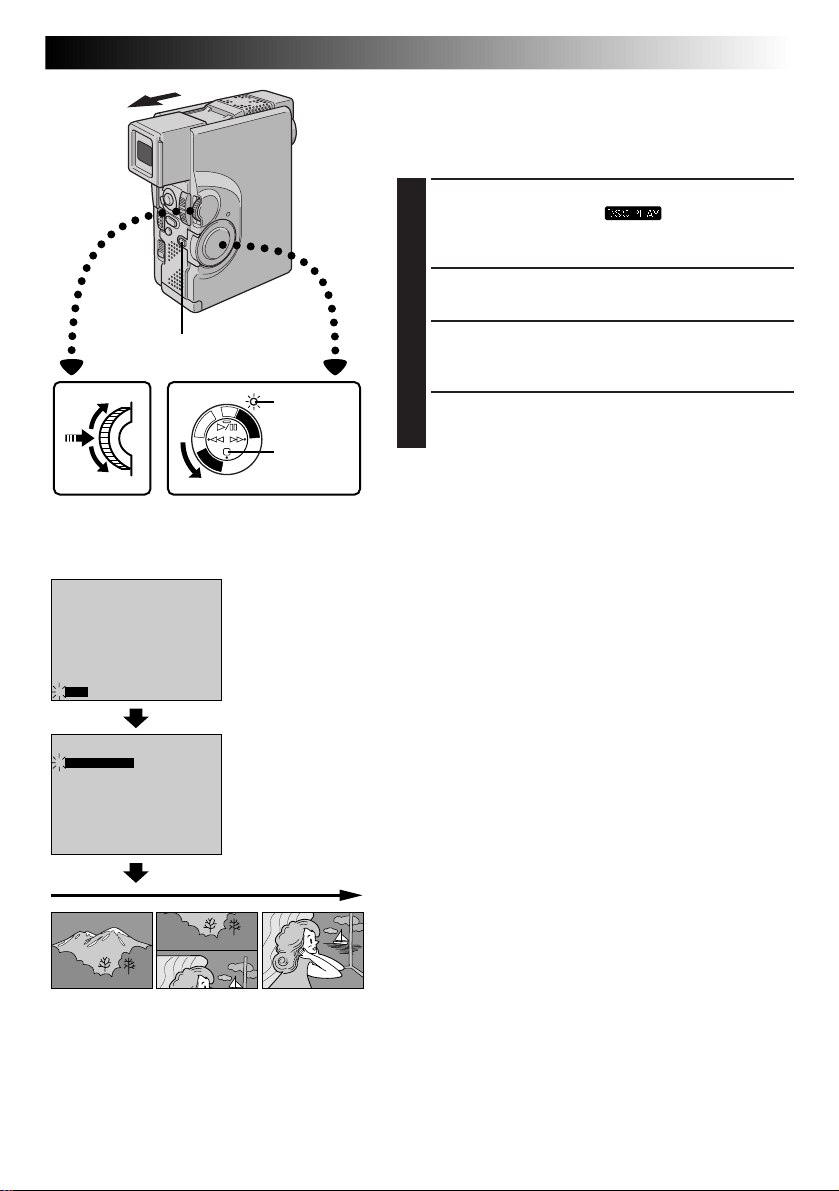
PLAYBACK
Advanced Features For D.S.C.
Slide Show
You can run through all the images stored in memory
automatically in numerical order. Each still image wipes in
over the last one from the bottom of the screen to the top.
SELECT OPERATION MODE
1
Set the Power Switch to “ ”, while pressing
down the Lock Button. Open the LCD monitor fully
or pull out the viewfinder fully.
ACCESS PLAYBACK MENU
2
Press MENU/SET. The Playback Menu appears.
EN57
MENU/SET Dial
Display
INDEX
SLIDE SHOW
MULTI VIEW
PROTECT
FILE DELETE
TITLE DELETE
FORMAT
4
END
INDEX
4
SLIDE SHOW
MULTI VIEW
PROTECT
FILE DELETE
TITLE DELETE
FORMAT
END
Lock Button
OFF
OFFIrTran-P
OFF
OFFIrTran-P
S
C
D
S
D
5
S
A
C
R
P
E
L
M
A
C
F
F
O
C
P
/
Y
A
L
P
Power Switch
Playback Menu
Power lamp
A
Y
Stop (5)
Button
START SLIDE SHOW
3
Move the highlight bar to “SLIDE SHOW” by rotating
MENU/SET, and press it. The Slide Show starts.
STOP SLIDE SHOW
4
Press 5.
NOTE:
While the Slide Show is being performed, the image may
be disturbed.
Page 58

58 EN
Picture Quality mode
Index number Selected image
EXIT
001 F 002 S 003 E
004 F
INDEX
005 F
PLAYBACK
006 F
Advanced Features For D.S.C. (cont.)
INDEX Screen
The images you shot can be displayed together with their
index information. Convenient for checking images shot
beforehand, the INDEX Screen also shows the Picture
Quality mode as well as which images are protected
against accidental erasure.
001: Index number
Index numbers are marked from 001. For example, when
10 images are stored (index number: 001 to 010), if three
images with index numbers 002, 004 and 006 are deleted
from memory, the remaining images are automatically
moved up to fill any gaps in the numerical sequence.
Therefore, the number of remaining images is 7, and the
new index numbers range from 001 to 007.
Protect icon
F/S/E: Picture Quality mode
Displays the Picture Quality mode of the stored image.
There are 3 modes available: FINE, STANDARD and
ECONOMY (in order of quality).
: Protect icon
When an image is protected against its accidental erasure,
a padlock mark appears next to the Picture Quality mode
indicator, and that image cannot be deleted.
Selected Image
An image is framed in green when it is selected. Rotate
MENU/SET to move the green frame to the desired image.
Page 59

MENU/SET Dial
Power lamp
S
C
D
S
D
5
S
A
C
R
E
M
A
C
F
F
O
C
P
/
Y
A
L
P
Power Switch
EN59
Index Playback
You can view the images stored in memory six at a time.
Use this mode when looking for an image you wish to
view.
SELECT OPERATION MODE
1
Set the Power Switch to “ ” while pressing
down the Lock Button. Open the LCD monitor fully
or pull out the viewfinder fully.
•A stored image is displayed.
ACCESS INDEX SCREEN
2
P
L
A
Y
Lock Button
MULTI SCREEN Button
Press MULTI SCREEN. The INDEX Screen appears.
OR
Select “INDEX” in the Playback Menu (To access the
Playback Menu, press MENU/SET).
DISPLAY DESIRED IMAGE
3
Rotate MENU/SET to move the green frame to the
desired image and press it. The image selected in the
INDEX Screen is displayed.
Display
4
INDEX
SLIDE SHOW
MULTI VIEW
PROTECT
FILE DELETE
TITLE DELETE
FORMAT
END
EXIT INDEX
001 F 002 S 003 E
004 F
005 F
OFF
OFFIrTran-P
006 F
Playback Menu
INDEX Screen
Playback Screen
Page 60

60 EN
MENU/SET Dial
Power Switch
Rewind (
Button
INDEX
SLIDE SHOW
4
MULTI VIEW
PROTECT
FILE DELETE
TITLE DELETE
FORMAT
END
2
Display
Lock Button
A
R
E
M
A
)
C
F
F
O
C
P
/
Y
SAME 16
OFFIrTran-P
S
C
D
S
D
5
S
C
P
L
A
Y
A
L
P
Playback Menu
PLAYBACK
Power lamp
Fast-Forward
3
) Button
(
Advanced Features For D.S.C. (cont.)
Multi-Image Screen
There are 3 Multi-Image Screens that can be created: 4split screens composed of the same image, 16-split screens
composed of the same image and 4-split screens composed of different, user-selected images.
SELECT OPERATION MODE
1
Set the Power Switch to “ ” while pressing
down the Lock Button. Open the LCD monitor fully or
pull out the viewfinder fully.
•A stored image is displayed.
•To create a Multi-Image Screen using the same
image, select an image before performing step 2.
ACCESS PLAYBACK MENU
2
Press MENU/SET. The Playback Menu appears.
SELECT FUNCTION
3
Rotate MENU/SET to move the highlight bar to
“MULTI VIEW” and press it. The selected parameter
blinks.
NOTES:
●
By printing a Multi-Image Screen to a printer that
supports sticker sheets, you can create stickers of any
image you like. For details, read your printer’s instruction manual.
●
To create a Multi-Image Screen using the same image
with a title/frame, first select the title/frame, referring to
“Superimposing A Title/Frame” (Z pg. 69), and then go
to step 2 above.
●
If a title/frame is superimposed over the playback picture
before step 2 is performed above, it will be impossible to
set “MULTI VIEW” to “SELECTED 4”.
Multi-Image Screen
NOTE:
If you wish to change the still images which
make up the Multi-Image Screen, go back to
normal playback and change the “MULTI
VIEW” setting in the Playback Menu.
TO CREATE A MULTI-IMAGE SCREEN
USING THE SAME IMAGE
Before doing the following, perform steps 1 through 3
above.
SELECT MODE
4
Rotate MENU/SET until the “SAME 4” or “SAME 16”
appears.
CREATE MULTI-IMAGE SCREEN
5
Press MENU/SET. A Multi-Image Screen displaying 4
or 16 frames of the same image appears.
END MULTI-IMAGE SCREEN
6
Set “MULTI VIEW” to “OFF” in the Playback Menu.
OR
Press 3 or 2 to display another image.
Page 61

MENU/SET Dial
Display
INDEX
SLIDE SHOW
4
MULTI VIEW
PROTECT
FILE DELETE
TITLE DELETE
FORMAT
END
EXIT
001 F 002 S 003 E
004 F
MULTI
005 F
SELECTED 4
OFFIrTran-P
006 F
Playback Menu
Multi-Image
Index Screen
Multi-Image Screen
EN61
TO CREATE A MULTI-IMAGE SCREEN
USING SELECTED IMAGES
Before doing the following, perform steps 1 through 3
(Z pg. 60).
SELECT MODE
4
Rotate MENU/SET until “SELECTED 4” appears and
press it. The Multi-Image Index Screen appears.
SELECT IMAGES
5
Rotate MENU/SET to move the green frame to the
desired image and press it. A check mark “ ”
appears on the selected image. Repeat this
procedure for all 4 images to be selected.
•To cancel the selection of an image, rotate MENU/
SET to move the green frame to the desired image
and press it. The check mark “ ” disappears.
CREATE MULTI-IMAGE SCREEN
6
Rotate MENU/SET upward to select “EXIT” and press
it. The Multi-Image Screen of the selected images
appears.
•The selected images are displayed in numerical
order from left to right and top to bottom.
•If you exit before selecting all 4 images, the MultiImage Screen is cancelled.
END MULTI-IMAGE SCREEN
7
Set “MULTI VIEW” to “OFF” in the Playback Menu.
OR
Press 3 or 2 to display another image.
NOTE:
If you wish to change the still images which make up the
Multi-Image Screen, go back to normal playback and
change the “MULTI VIEW” setting in the Playback Menu.
Page 62

62 EN
PLAYBACK
Protecting Images
The Protect mode helps prevent the accidental erasure of
images. When a padlock mark is displayed next to the
Picture Quality Mode indication, that image cannot be
deleted.
1
Advanced Features For D.S.C. (cont.)
SELECT OPERATION MODE
Set the Power Switch to “ ” while pressing
down the Lock Button. Open the LCD monitor fully or
pull out the viewfinder fully.
•A stored image is displayed.
Lock Button
Display
INDEX
SLIDE SHOW
MULTI VIEW
4
PROTECT
FILE DELETE
TITLE DELETE
FORMAT
END
EXIT
001 F 002 S 003 E
004 F
Normal playback
PROTECT
005 F
OFF
OFFIrTran-P
006 F
S
C
D
S
D
5
S
A
C
R
P
E
L
M
A
A
Y
C
F
F
O
C
P
/
Y
A
L
P
Power SwitchMENU/SET Dial
Playback Menu
PROTECT Index
Screen
Power lamp
Padlock mark
ACCESS PLAYBACK MENU
2
Press MENU/SET. The Playback Menu appears.
SELECT FUNCTION
3
Rotate MENU/SET to move the highlight bar to
“PROTECT” and press it. The PROTECT Index Screen
appears.
TO PROTECT AN IMAGE
Before doing the following, perform steps 1 through 3
above.
SELECT IMAGE
4
Rotate MENU/SET to move the green frame to the
desired image and press it. A “ ” padlock mark
appears on the selected image.
Repeat this procedure for all images you do not wish
to delete by accident.
END SELECTION
5
Rotate MENU/SET upward to select “EXIT” and press
it. The normal playback screen appears.
NOTE:
When the memory is initialised or corrupted, even
protected images are deleted. If you do not want to lose
important images, we recommend you to transfer them to
a PC and save them.
Page 63

MENU/SET Dial
Display
EXIT PROTECT
001 F 002 S 003 E
005 F
004 F
EXIT PROTECT
001 F 002 S 003 E
004 F
005 F
006 F
006 F
PROTECT Index
Screen
EN63
TO REMOVE PROTECTION
Before doing the following, perform steps 1 through 3
(Z pg. 62).
SELECT IMAGES
4
Rotate MENU/SET to move the green frame to the
desired image and press it. The “ ” padlock mark
located above the image disappears and the image is
no longer protected.
Repeat this procedure for all images from which you
wish to remove protection.
END PROTECTION
5
Rotate MENU/SET upward to select “EXIT” and press
it. The normal playback screen appears.
Normal playback
Page 64
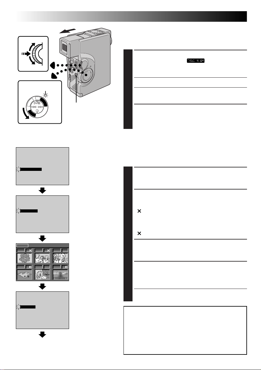
64 EN
MENU/SET Dial
Power lamp
A
R
E
M
A
C
F
F
O
C
P
/
Y
Power Switch
PLAYBACK
Advanced Features For D.S.C. (cont.)
Deleting Images
Previously shot images can be deleted either one at a time
or all at once.
SELECT OPERATION MODE
1
Set the Power Switch to “ ” while pressing
down the Lock Button. Open the LCD monitor fully or
pull out the viewfinder fully.
•A stored image is displayed.
ACCESS PLAYBACK MENU
S
C
D
S
D
5
S
C
P
L
A
Y
A
L
P
Lock Button
2
Press MENU/SET. The Playback Menu appears.
SELECT FUNCTION
3
Rotate MENU/SET to move the highlight bar to “FILE
DELETE” and press it. The FILE DELETE Screen
appears.
Display
INDEX
SLIDE SHOW
MULTI VIEW
PROTECT
4
FILE DELETE
TITLE DELETE
FORMAT
END
ALL
4
SELECTED
CANCEL
NEXT DELETE
001 F 002 S 003 E
004 F
4
EXECUTE
CANCEL
Normal playback
OFF
OFFIrTran-P
FILE DELETE
005 F
006 F
Playback Menu
FILE DELETE Screen
DELETE Index Screen
Deletion Confirmation
Screen
TO SELECT AN IMAGE BY BROWSING
IMAGES STORED IN MEMORY
Before doing the following, perform steps 1 through 3
above.
SELECT MODE
4
Rotate MENU/SET to select “SELECTED” and press it.
The DELETE Index Screen appears.
SELECT IMAGE
5
Rotate MENU/SET to move the green frame to the
desired image that you wish to delete and press it. An
“ ” appears above the selected image.
Repeat this procedure for all images that you wish to
delete.
To deselect an image, press MENU/SET again. The
“ ” disappears.
END SELECTION
6
Rotate MENU/SET upward to select “NEXT” and
press it. The Deletion Confirmation Screen appears.
DELETE IMAGE
7
Rotate MENU/SET to select “EXECUTE” and press it.
The selected images are deleted and the normal
playback screen appears.
•If you wish to cancel deletion, rotate MENU/SET to
select “CANCEL” and press it.
CAUTION:
While deleting images, never remove the
MultiMediaCard or disconnect power, as this may
cause the memory to be corrupted. Also, be sure to
use the AC Power Adapter/Charger, as a malfunction
may occur if the battery become exhausted halfway
through the operation.
Page 65
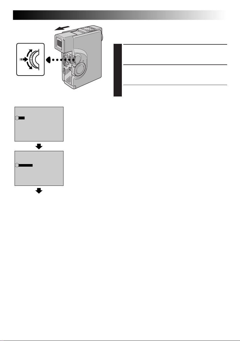
MENU/SET Dial
Display
FILE DELETE
4
ALL
SELECTED
CANCEL
4
EXECUTE
CANCEL
FILE DELETE Screen
Deletion
Confirmation Screen
EN65
TO DELETE ALL IMAGES
Before doing the following, perform steps 1 through 3
(Z pg. 64).
SELECT MODE
4
Rotate MENU/SET to select “ALL” and press it. The
Deletion Confirmation Screen appears.
DELETE IMAGES
5
Rotate MENU/SET to select “EXECUTE” and press it.
All the images are deleted.
•If you wish to cancel deletion, rotate MENU/SET to
select “CANCEL” and press it.
Normal playback
Page 66
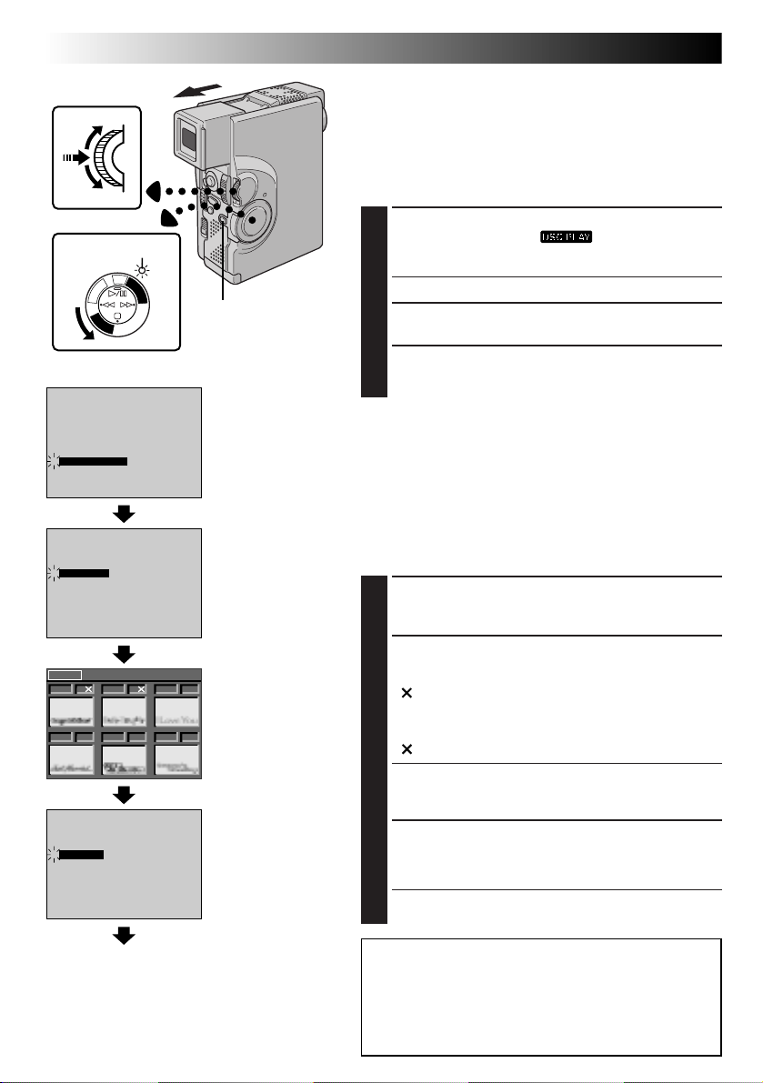
66 EN
MENU/SET Dial
Power lamp
M
A
C
F
F
O
INDEX
SLIDE SHOW
MULTI VIEW
PROTECT
FILE DELETE
4
TITLE DELETE
FORMAT
END
S
C
D
S
5
A
R
E
C
P
/
Y
A
L
P
Display
PLAYBACK
Advanced Features For D.S.C. (cont.)
Deleting Titles/Frames
A title/frame created on a PC can be transferred to a
MultiMediaCard using the provided software. Titles/frames that
have been transferred to a MultiMediaCard can be deleted
when they are no longer needed.
There are 2 ways of deleting previously created titles/frames:
by browsing through titles/frames individually or by deleting
them all at once.
SELECT OPERATION MODE
1
Set the Power Switch to “ ” while pressing
down the Lock Button. Open the LCD monitor fully or
D
S
C
P
L
A
Y
OFF
OFFIrTran-P
Lock Button
Power Switch
Playback Menu
pull out the viewfinder fully.
•A stored image is displayed.
ACCESS PLAYBACK MENU
2
Press MENU/SET. The Playback Menu appears.
SELECT FUNCTION
3
Rotate MENU/SET to move the highlight bar to “TITLE
DELETE” and press it. The TITLE DELETE Screen appears.
NOTES:
●
If titles/frames created on a PC have not been transferred to
a MultiMediaCard, it is not possible to delete them using
these steps.
●
The titles/frames in the camcorder’s memory cannot be
deleted.
TITLE DELETE
ALL
4
SELECTED
CANCEL
NEXT DELETE
013 F 014 F 015 F
017 F
016 F
4
EXECUTE
CANCEL
Normal playback
018 F
TITLE DELETE Screen
DELETE Index Screen
Deletion Confirmation
Screen
TO SELECT A TITLE/FRAME BY BROWSING
TITLES/FRAMES STORED IN MEMORY
Before doing the following, perform steps 1 through 3 above.
SELECT MODE
4
Rotate MENU/SET to select “SELECTED” and press it.
The DELETE Index Screen appears.
SELECT TITLE/FRAME
5
Rotate MENU/SET to move the green frame to the
desired title/frame that you wish to delete and press it. An
“ ” appears above the selected title/frame.
Repeat this procedure for all titles/frames that you wish to
delete.
To deselect a title/frame, press MENU/SET again. The
“ ” disappears.
END SELECTION
6
Rotate MENU/SET upward to select “NEXT” and press it.
The Deletion Confirmation Screen appears.
DELETE TITLE/FRAME
7
Rotate MENU/SET to select “EXECUTE” and press it. The
selected titles/frames are deleted and the normal
playback screen appears.
•If you wish to cancel deletion, rotate MENU/SET to
select “CANCEL” and press it.
CAUTION:
While deleting titles/frames, never remove the
MultiMediaCard or disconnect power, as this may cause
the memory to be corrupted. Also, be sure to use the AC
Power Adapter/Charger, as a malfunction may occur if the
battery become exhausted halfway through the operation.
Page 67
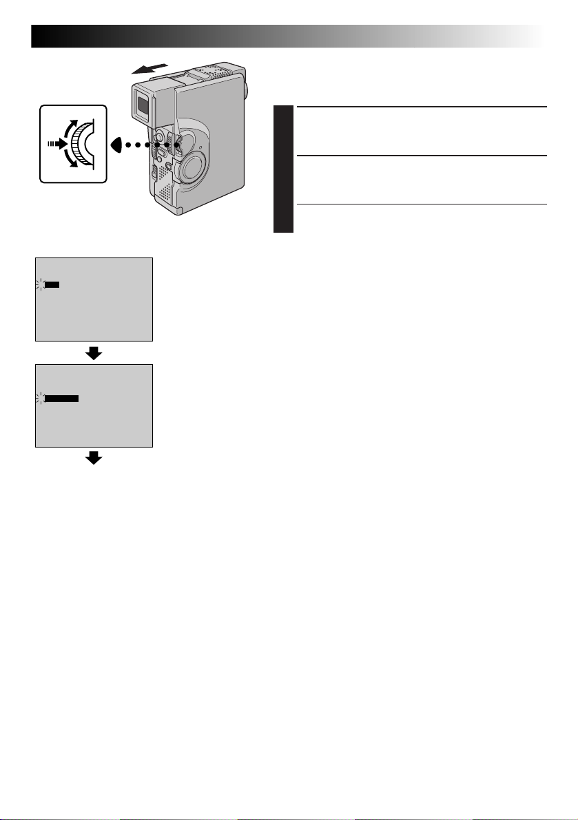
MENU/SET Dial
Display
TITLE DELETE
4
ALL
SELECTED
CANCEL
4
EXECUTE
CANCEL
TITLE DELETE Screen
Deletion Confirmation
Screen
EN67
TO DELETE ALL TITLES/FRAMES
Before doing the following, perform steps 1 through 3
(Z pg. 66).
SELECT MODE
4
Rotate MENU/SET to select “ALL” and press it. The
Deletion Confirmation Screen appears.
DELETE TITLE/FRAME
5
Rotate MENU/SET to select “EXECUTE” and press it.
All the titles/frames are deleted.
•If you wish to cancel deletion, rotate MENU/SET to
select “CANCEL” and press it.
Normal playback
Page 68
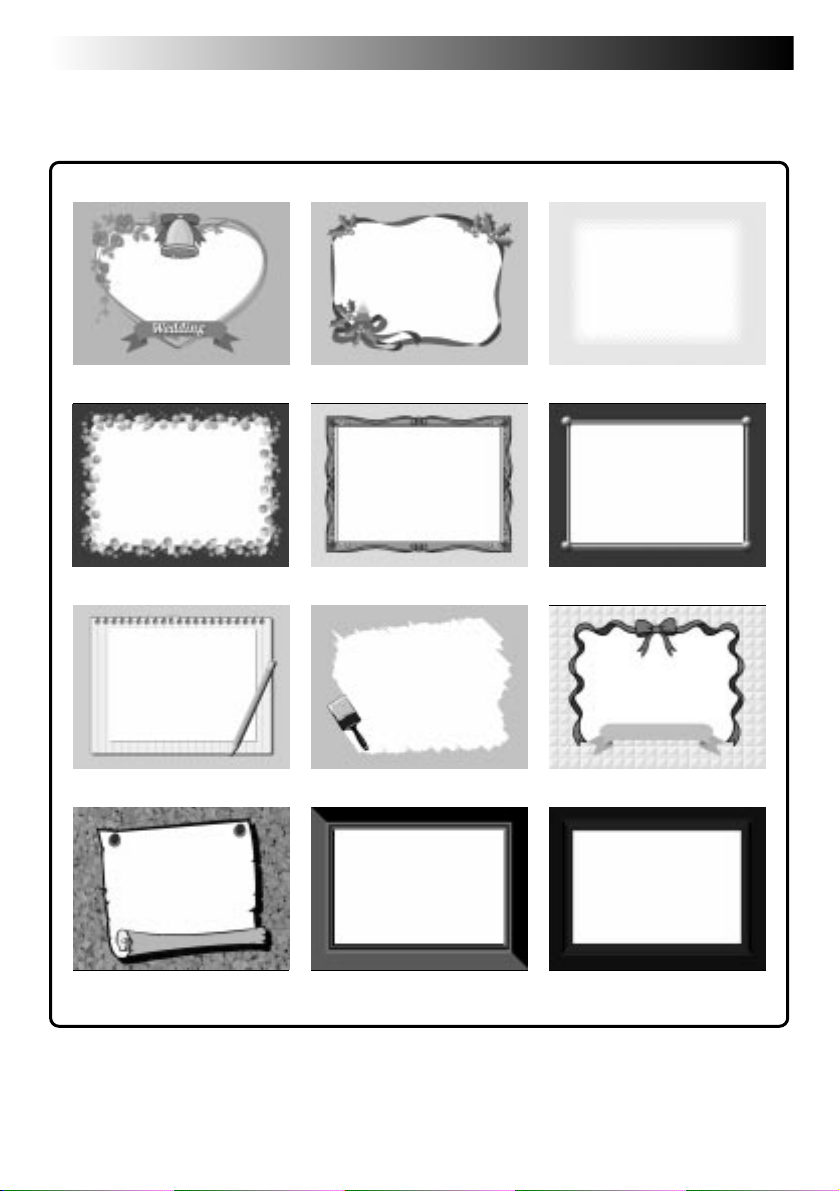
68 EN
Types Of Titles/Frames
This camcorder has 12 preset titles/frames stored in its memory, as shown in the following illustration.
PLAYBACK
Advanced Features For Video And D.S.C.
Page 69
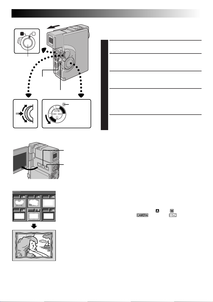
Operation Switch
A M
EN69
Superimposing A Title/Frame
A title/frame can be superimposed over the playback
picture (image).
START PLAYBACK
1
Play back a tape or images in a MultiMediaCard.
START/STOP
Button
PHOTO
(SNAPSHOT)
Button
Lock Button
R
E
M
A
C
F
F
O
C
P
/
Power lamp
S
C
D
S
D
5
S
A
C
P
L
A
Y
Y
A
L
P
SUPERIMPOSE TITLE/FRAME
2
Press TITLE (/Frame). A title/frame is superimposed
over the playback picture (image).
ACCESS TITLE/FRAME INDEX SCREEN
3
Press MULTI SCREEN. The Title/Frame Index Screen
appears.
SELECT DESIRED TITLE/FRAME
4
Rotate MENU/SET to move the green frame to the
desired title/frame and press it. The selected title/
frame is superimposed over the playback picture
(image).
MAKE TITLE/FRAME DISAPPEAR
5
Press TITLE (/Frame). The selected title/frame
disappears.
MENU/SET Dial
Display
EXIT INDEX
001 002 003
Power Switch
MULTI SCREEN
Button
TITLE (/Frame)
Button
Title/Frame Index
Screen
NOTES:
●
A title/frame created on a PC can be transferred to a
MultiMediaCard using the provided software. Transferred
titles/frames are displayed from title/frame index number
013, and they can be used together with the titles/frames in
the camcorder’s memory. For details on creating/transferring
titles/frames, refer to the software instructions.
●
If Snapshot recording/playback is performed with a title/
frame, the images will be recorded/played back in the FULL
mode regardless of the selected Snapshot mode.
●
Depending on the images you record or play back, the title/
frame outline may become grainy or vague.
●
During title/frame display, it is not possible to change the
Snapshot mode.
To Record An Image With A Title/Frame . . .
.... You can also record an image with a title/frame by
performing the following procedure.
005
004
006
1. Set the Operation Switch to “ ” or “ ”. Then, set the
Power Switch to “ ”, “5S” or “ ” while
pressing down the Lock Button.
2. Press TITLE (/Frame) to superimpose a title/frame on an
image.
3. Press MULTI SCREEN to display the Title/Frame Index
Screen.
4. Rotate MENU/SET to move the green frame to the
desired title/frame and press it. The selected title/frame
is superimposed over the image.
5. Press START/STOP or PHOTO (SNAPSHOT) to start
recording. The image is recorded with the selected title/
frame.
6. Press TITLE (/Frame) to make the title/frame disappear.
NOTES:
●
During recording, it is not possible to change the title/frame, as the Title/Frame Index Screen does not appear if
MULTI SCREEN is pressed.
●
The titles/frames displayed in the Title/Frame Index Screen may be jittery.
Page 70
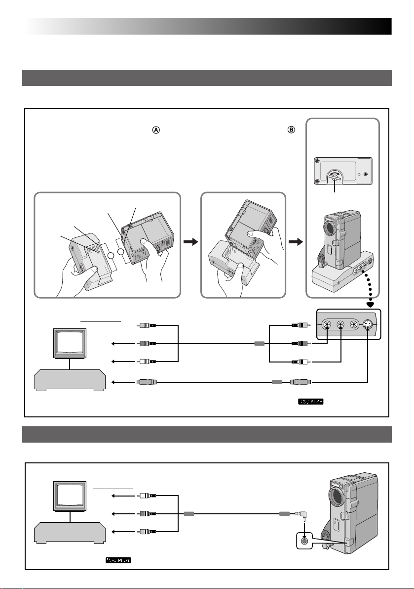
70 EN
PLAYBACK
Basic Connections
These are some basic types of connections. When making the connections, refer also to your VCR and TV
instruction manuals.
A. Connection to a TV or VCR equipped with an S-VIDEO IN and A/V input (RCA type) connectors
Use the provided Docking Station, Audio/Video (A/V) cable [RCA plug to RCA plug] and S-Video cable.
Docking Station Attachment
1 Align the edge of the camcorder with the edge of the Docking Station .
2 Align the direction stud and screw on the Docking Station with the stud hole
and tripod mounting socket on the camcorder.
3 Tighten the screw.
•When removing the camcorder, loosen the screw and detach the camcorder.
12
Tripod mounting socket
Screw
Stud
To TV or VCR
A
B
Stud hole
Yellow:
Not connected
Yellow:
Not connected
TV
Red to AUDIO R**
White to AUDIO L**
A/V cable
[RCA plug to RCA
plug] (provided)
Red to AUDIO R OUT**
White to AUDIO L OUT**
VCR
To S-VIDEO IN
** The Audio cable is not required for watching still images with the Power Switch set to “ ”.
S-Video cable (provided)
3
Bottom of
Docking Station
Screw Knob
To S-VIDEO OUT
B. Connection to a TV or VCR equipped only with A/V input connectors
Use the provided Audio/Video (A/V) cable [mini-plug to RCA plug].
* When connecting the cables, open this cover.
To TV or VCR
TV
White to AUDIO L**
Red to AUDIO R**
VCR
** The Audio cable is not required for watching still images with the
Power Switch set to “
Yellow to VIDEO
”.
A/V cable
[mini-plug to RCA
plug] (provided)
Connector
cover*
To
AV OUT
Page 71

CONFIRM POWER-OFF STATUS
1
Make sure the camcorder’s power is off.
CONNECT CAMCORDER TO TV OR
2
VCR
Connect as shown in the illustration (Z pg. 70).
If Using A VCR . . . go to step 3.
If not . . . go to step 4.
CONNECT VCR OUTPUT TO TV
3
INPUT
Refer to your VCR’s instruction manual.
SUPPLY POWER
4
Turn on the camcorder, the VCR and the TV.
SELECT MODE
5
Set the VCR to its AUX input mode, and set the
TV to its VIDEO mode.
To choose whether or not the following displays
appear on the connected TV . . .
•Date/Time, Time Code
.... set to “ON” or “OFF” in the Playback Menu
(Z pg. 54).
•Playback Sound Mode Display
.... set the Operation Switch to “ ”, then set the
Power Switch to the camera position
(“ ”, “5S” or “ ”) while pressing
down the Lock Button. Press MENU/SET and
set “ON SCREEN” in the Date/Time Menu
(Z pg. 34 – 38) to “ON” or “OFF”. Then, set
the Power Switch back to “ ”.
EN71
NOTES:
●
It is recommended to use the AC Power Adapter/
Charger as the power supply instead of the battery
pack. (Z pg. 9)
●
Never connect any other Audio/Video cable than
the provided Audio/Video cable (mini-plug to RCA
plug) to the camcorder’s AV OUT connector.
●
When using the cables (except Audio/Video cable
with mini-plug to RCA plug), make sure you
connect the end of the cable with the core filter to
the camcorder. The core filter reduces interference.
●
To monitor the picture and sound from the
camcorder without inserting a tape, set the
camcorder’s Power Switch to “ ”, “5S” or
“ ”, then set your TV to the appropriate input
mode.
●
Make sure you adjust the TV sound volume to its
minimum level to avoid a sudden burst of sound
when the camcorder is turned on.
●
If you have a TV or speakers that are not specially
shielded, do not place the speakers adjacent to the
TV as interference will occur in the camcorder
playback picture.
●
To keep the camcorder’s display from appearing on
the TV screen during playback, set “INDICATION”
to “OFF” in the Playback Menu (Z pg. 54) and
press DISPLAY on the remote control.
●
While the Audio/Video cable is connected to the
AV OUT connector, sound cannot be heard from
the speaker.
Page 72
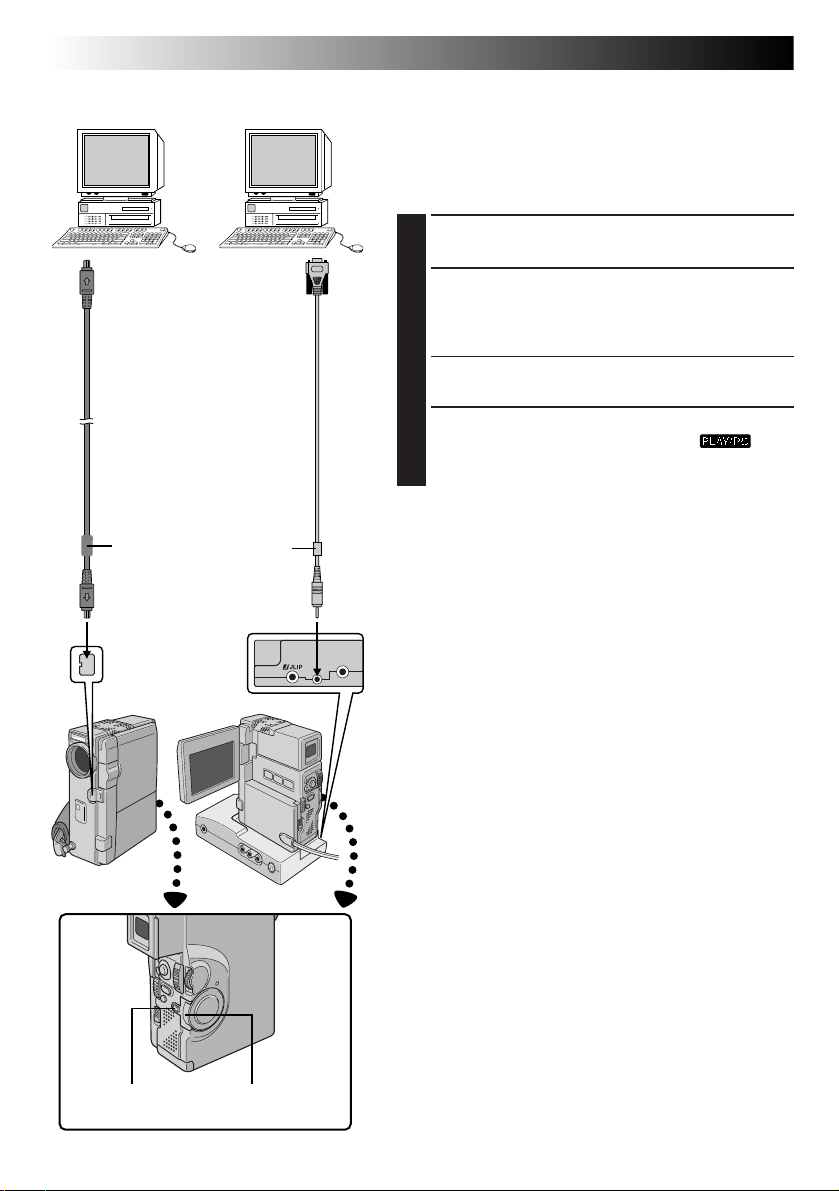
72 EN
PC with DV connectorequipped capture board
PC
PLAYBACK
Advanced Connections
Connection To A Personal Computer
This camcorder can transfer still images to a personal
computer by using the provided software when connected
as shown in the illustration. It is also possible to transfer
still images to a personal computer with a DV connectorequipped capture board installed.
CONFIRM POWER-OFF STATUS
1
Make sure the camcorder and PC are turned off.
To DV
connector
DV cable
(optional)
Core filter
To DV
IN/OUT
Open the
connector
cover.
To
RS-232C
PC
connection
cable
(provided)
Core filter
To PC
(DIGITAL
STILL)
CONNECT TO PC
2
Connect the camcorder or Docking Station to your
PC using the appropriate cable as shown in the
illustration.
•To attach the camcorder to Docking Station, refer to
“Docking Station Attachment” on pg. 70.
TURN ON POWER
3
Turn the camcorder’s Power Switch to “ ”
while pressing down the Lock Button and turn on the
PC.
NOTES:
●
It is recommended to use the AC Power Adapter/
Charger as the power supply instead of the battery pack
(Z pg. 9).
●
Never connect the PC connection cable and the DV
cable simultaneously to the camcorder. Connect only
the cable you wish to use to the camcorder.
●
The date/time information cannot be captured into PC.
●
Also refer to the instruction manuals of the provided
Software and the DV connector-equipped capture
board.
●
Be sure to use a DV cable with the core filter.
Power SwitchLock Button
Page 73
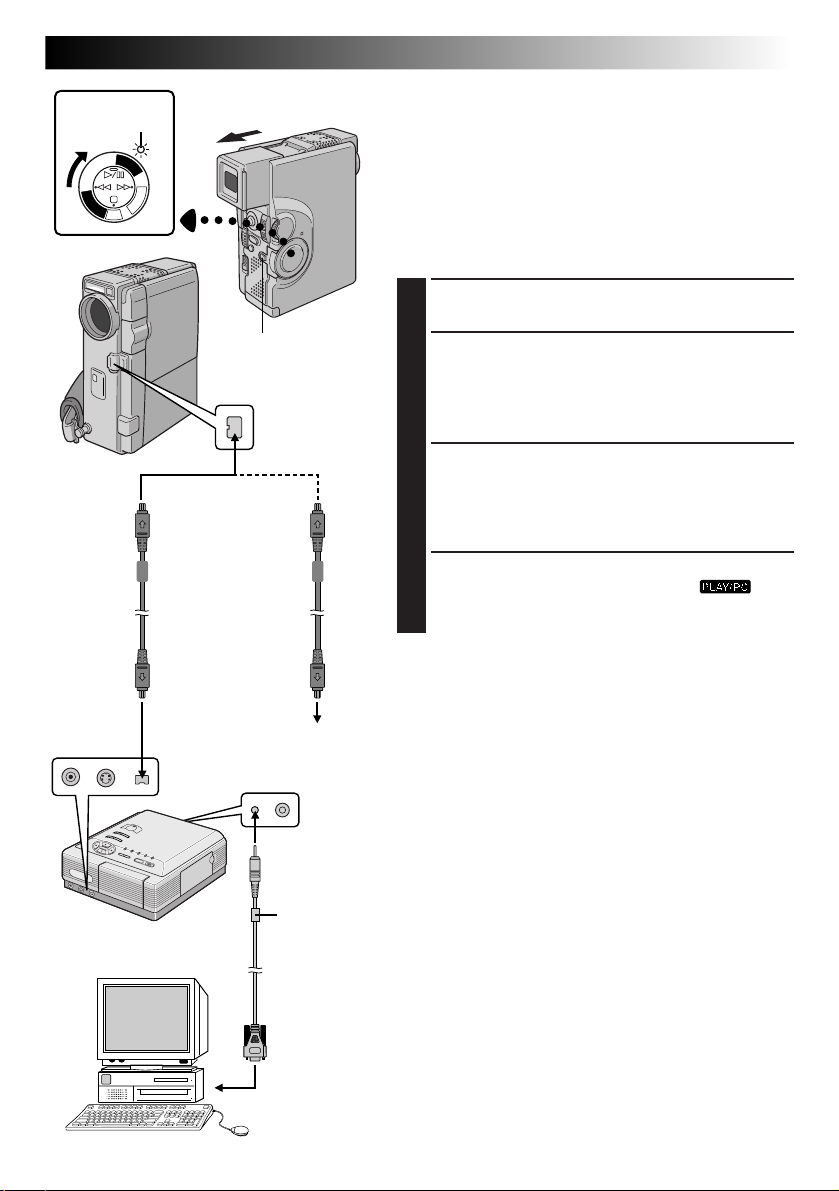
Power lamp
Y
A
L
P
C
S
D
To DV IN
connector
Digital Printer
P
L
A
Y
/
P
C
O
F
F
C
A
M
E
R
A
5
S
D
S
C
Power Switch
Lock Button
Open the
connector cover.
To DV IN/OUT
DV cable (optional)
To D V
connector
Video unit equipped
with a DV input
connector
To P C
connector
PC
connection
cable
(provided)
Core filter
EN73
Connection To A Video Unit Equipped With
A DV Connector
Connection to the Digital Printer GV-DT3 (optional) allows
you to print out the images or to transfer the captured
image from the Digital Printer to a personal computer. It is
also possible to copy recorded scenes from the camcorder
onto another video unit equipped with a DV connector.
This function is called Digital Dubbing (Z pg. 75), which
offers virtually no image or sound deterioration.
CONFIRM POWER-OFF STATUS
1
Make sure all the units are turned off.
CONNECT CAMCORDER TO PRINTER
2
OR VIDEO UNIT EQUIPPED WITH DV
INPUT CONNECTOR
Make connections to the device you want to connect
to using the DV cable, as shown in the illustration.
CONNECT PRINTER TO PC
3
(IF NECESSARY)
Connect the PC connection cable (provided) to the
printer's PC connector and the PC’s RS-232C
connector.
TURN ON POWER
4
Turn the camcorder’s Power Switch to “ ”
while pressing down the Lock Button and turn on the
other units.
NOTES:
●
It is recommended to use the AC Power Adapter/
Charger as the power supply instead of the battery
pack. (Z pg. 9)
●
For Digital Dubbing, this camcorder can be connected
only to one device at a time. This camcorder can also be
used as a recorder.
●
If Still Playback, Slow-Motion Playback, Fast-Forward or
Rewind is attempted with the camcorder connected to a
video unit via the DV connector, the image will take on
an effect similar to a coloured mosaic pattern or it will
become black.
●
Also refer to the instruction manuals of the connected
units.
●
Be sure to use a DV cable with the core filter.
PC
To RS-232C
Page 74

74 EN
Yellow to
VIDEO OUT*
Play/Pause (4/6) Button
Red to
AUDIO
R OUT
White to
AUDIO
L OUT
To
S-VIDEO
OUT
Power Switch
DUBBING
Dubbing Images/Sounds Recorded On A
Tape To Another Tape
CONNECT EQUIPMENT
1
Following the illustration at left, connect the
camcorder and the VCR. Also refer to pg. 70 and 71.
PREPARE FOR DUBBING
2
Set the camcorder’s Power Switch to “ ”, turn
on the VCR’s power, and insert the appropriate
cassettes in the camcorder and the VCR.
SELECT VCR MODE
3
Engage the VCR’s AUX and Record-Pause modes.
FIND EDIT-IN POINT
4
Engage the camcorder’s Play mode to find a spot just
before the edit-in point. Once it is reached, press 4/6
on the camcorder.
START EDITING
5
Press 4/6 on the camcorder and engage the VCR’s
Record mode.
STOP EDITING TEMPORARILY
6
Engage the VCR’s Record-Pause mode and press 4/6
on the camcorder.
TV
S-Video cable
(provided)
A/V cable
[RCA plug to RCA
plug] (provided)
To AUDIO,
VIDEO*
and S-VIDEO IN
connectors
VCR (Recording deck)
* Connect when the S-Video cable is not used.
EDIT MORE SEGMENTS
7
Repeat steps 4 through 6 for additional editing, then
stop the VCR and camcorder when finished.
NOTES:
●
You can use the AV OUT connector on the camcorder
for connection.
●
You can use Playback Zoom (Z pg. 82) or Playback
Special Effects (Z pg. 83) in step 5.
●
Before you start dubbing, make sure that the indications
do not appear on the connected TV. If they do appear
during dubbing, they are being recorded onto the new
tape.
To clear the Playback Sound Mode Display, press
DISPLAY on the RM-V713U remote control (provided).
●
Select “DISPLAY” and “TIME CODE” from the Playback
Menu (Z pg. 54) to show or hide the Date/Time and
the Time Code on the recording.
●
To keep all the camcorder’s indications from appearing
on the VCR, set “INDICATION” to “OFF” in the
Playback Menu (Z pg. 54) and press DISPLAY on the
remote control.
Page 75

P
L
A
Y
/
P
C
O
Y
A
E
L
R
P
A
C
5
S
S
D
D
S
C
Power Switch
EN75
Digital Dubbing Of Recorded Images/
F
F
C
A
M
Sounds Between Tapes
It is also possible to copy recorded scenes from the
camcorder onto other video unit equipped with a DV
connector. Since a digital signal is sent, there is little if any
image or sound deterioration.
CONFIRM POWER-OFF STATUS
1
Make sure the camcorder’s power is off.
Lock Button
Open the
connector
cover.
To D V
IN/OUT
To DV IN
DV cable
(optional)
Video unit equipped
with DV connector
4
PLAY (
STOP (5)
)
TW
RM-V713U
(provided)
MAKE CONNECTIONS
2
Connect the camcorder to your video unit equipped
with a DV connector using the DV cable (optional) as
shown in the illustration.
START PLAYBACK
3
Press 4 to play back the source tape.
START RECORDING
4
While watching the playback on the monitor, engage
the DV connector-equipped video unit’s record mode
from the spot on the source tape you want to begin
recording.
NOTES:
●
It is recommended to use the AC Power Adapter/
Charger as the power supply instead of the battery pack
(Z pg. 9).
●
If the remote control is used when both the player and
recorder are JVC video units, both units will perform the
same operation. To prevent this from happening, press
the buttons on both units.
●
For Digital Dubbing, this camcorder can be connected
only to one device at a time. This camcorder can also be
used as a recorder.
●
If a blank portion or disturbed image is played back on
the player during dubbing, the dubbing may stop so that
an unusual image is not dubbed.
●
Even though the DV cable is connected correctly,
sometimes the image may not appear in step 3. If the
above occurs, turn off power and make connections
again.
●
If “Playback Zoom” (Z pg. 82), “Playback Special
Effects” (Z pg. 83), “Superimposing A Title/Frame”
(Z pg. 69) or “Snapshot” is attempted during playback,
only the original playback image recorded on the tape is
output from the DV IN/OUT connector.
●
Be sure to use a DV cable with the core filter.
To Use This Camcorder As A Recorder . . .
1. Turn the Power Switch to “ ” while pressing down the Lock Button.
2. Connect the DV cable as shown in the illustration and load a cassette to record on.
3. Press the Recording Start/Stop Button to engage the Record-Pause mode. “DV IN” appears on the screen.
4. Press the Recording Start/Stop Button to start recording. “DV IN” changes to “
5. Press the Recording Start/Stop Button again to engage the Record-Pause mode. “
DV IN
DV IN
”.
” returns to “DV IN”.
NOTES:
●
During Digital Dubbing, the image is dubbed using the recording mode selected in the Mode Menu (Z pg. 13).
●
Digital Dubbing is performed in the sound mode recorded on the original tape, regardless of the current
“SOUND MODE” setting (Z pg. 39).
●
During
Digital Dubbing, no signal is output from the AV OUT connector.
Page 76

76 EN
DUBBING
(cont.)
Dubbing Images Stored In A
MultiMediaCard To A Tape
Images can be dubbed from a MultiMediaCard to a tape.
LOAD CASSETTE AND
1
MULTIMEDIACARD
PHOTO
(SNAPSHOT)
Button
Lock Button
Power Switch
S
5
A
R
E
M
A
C
F
F
O
C
P
/
Y
A
L
P
Rewind (
Button
S
C
D
D
S
C
P
L
A
Y
2
)
TO COPY TO TAPE
PUSH “SNAPSHOT
Power lamp
Display
Fast-Forward
3
) Button
(
SP
TAPE
SELECT OPERATION MODE
2
Set the Power Switch to “ ” while pressing
down the Lock Button. Open the LCD monitor fully
or pull out the viewfinder fully.
SELECT IMAGE TO BE DUBBED
3
Perform Index Playback (Z pg. 59), Auto Playback
(Z pg. 56) or press 2 or 3 to select the image
you wish.
START DUBBING
4
Press PHOTO (SNAPSHOT). The message “TO
COPY TO TAPE PUSH SNAPSHOT” is displayed for
approx. 5 seconds. While the message is displayed,
press PHOTO (SNAPSHOT) again and the selected
image is recorded on the tape for approx. 5 seconds.
•The “SP” or “LP”, TAPE and tape running indicators
disappear when dubbing is complete.
NOTE:
If PHOTO (SNAPSHOT) is pressed in step 4 when the
tape’s erase protection switch is set to “SAVE”, the message
“COPYING FAILED” is displayed.
SP
444
TAPE
Page 77
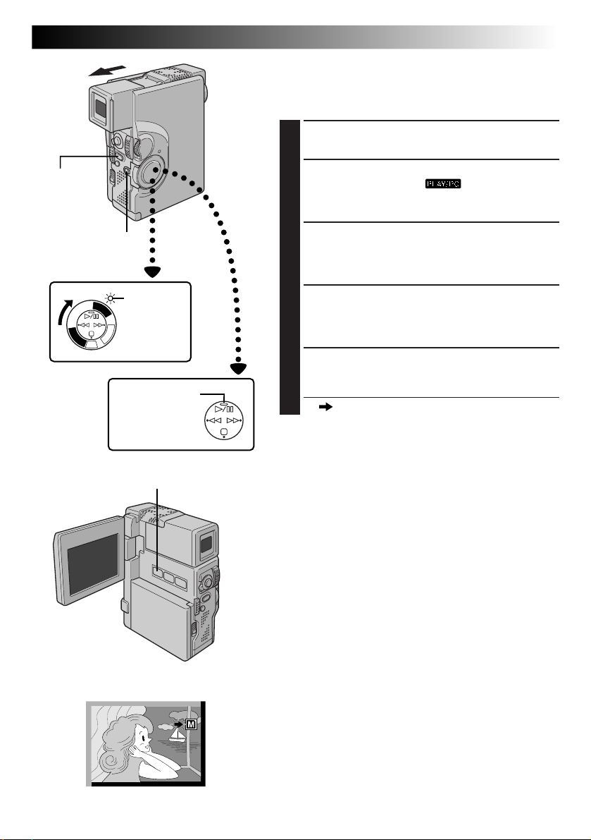
EN77
Dubbing Images Recorded On A Tape To A
MultiMediaCard
Images can be dubbed from a tape to a MultiMediaCard.
LOAD CASSETTE AND
1
MULTIMEDIACARD
PHOTO
(SNAPSHOT)
Button
Lock Button
Power Switch
Y
A
L
P
C
S
D
Power lamp
P
L
A
Y
/
P
C
O
F
F
C
A
M
E
R
A
5
S
D
S
C
Play/Pause (4/6)
Button
SNAPSHOT MODE Button
SELECT OPERATION MODE
2
Set the Power Switch to “ ” while pressing
down the Lock Button. Open the LCD monitor fully
or pull out the viewfinder fully.
SELECT IMAGE TO BE DUBBED
3
Press 4/6 to start playback. At the moment you find
the image you wish to dub, press it again to engage
Still Playback.
SELECT SNAPSHOT MODE
4
Press SNAPSHOT MODE to select the Snapshot
mode to use for dubbing the image to the
MultiMediaCard.
START COPYING
5
Press PHOTO (SNAPSHOT). The image is stored in
the MultiMediaCard.
•“ ” blinks during dubbing.
NOTES:
●
If PHOTO (SNAPSHOT) is pressed in step 5 when a
MultiMediaCard is not loaded, the message “COPYING
FAILED” is displayed.
●
If an image recorded on the tape using the WIDE mode
(Z pg. 37) is dubbed to a MultiMediaCard, the WIDE
mode identifying signal is not dubbed with it.
Display
SP
4
Page 78

78 EN
MENU/SET Dial
Power Switch
Rewind (
2
Button
Infrared transmitter/receiver
)
Lock Button
S
C
D
S
5
A
R
E
M
A
C
F
F
O
C
P
/
Y
A
L
P
D
S
C
P
L
A
Y
Power lamp
Fast-Forward
(3) Button
DUBBING
(cont.)
Copying Images Using Infrared
Communication [IrTran-P]
Images stored in a MultiMediaCard can be copied
between this camcorder and another piece of equipment
that supports IrDA (IrTran-P) infrared communication,
regardless of its manufacturer.
The following procedure is described using two
GR-DVX7 camcorders as an example. For use of other
video units, refer to their respective instructions.
LOAD MULTIMEDIACARDS
1
[For both receiving and transmitting camcorders]
Insert MultiMediaCards into both receiving and
transmitting camcorders.
SELECT OPERATION MODE
2
[For both receiving and transmitting camcorders]
Set the Power Switch to “ ” while pressing
down the Lock Button. Open the LCD monitor fully
or pull out the viewfinder fully.
ACCESS PLAYBACK MENU
3
[For both receiving and transmitting camcorders]
Press MENU/SET. The Playback Menu appears.
SELECT FUNCTION
4
[For both receiving and transmitting camcorders]
Rotate MENU/SET to move the highlight bar to
“IrTran-P” and press it. The selected parameter blinks.
15° 15°
15° 15°
< 50 cm
SELECT IrTran-P MODE
5
[For transmitting camcorder]
Rotate MENU/SET until “TRANSMIT” appears and
press it. The normal playback screen appears.
SELECT IMAGE TO BE COPIED
6
[For transmitting camcorder]
Perform Index Playback (Z pg. 59), Auto Playback
(Z pg. 56) or press 2 or 3 to select the desired
image.
Page 79

A M
START/STOP/
TRANS Button
MENU/SET Dial
EN79
POSITION CAMCORDERS
7
[For both receiving and transmitting camcorders]
Position the transmitting and receiving camcorders so
that their infrared transmitter and receiver face each
other.
•The distance between them should be less than
50 cm and the transmitter and receiver should be
angled no more than 15˚ to each other.
TRANSMIT IMAGE
8
[For transmitting camcorder]
Press START/STOP/TRANS. Image transmission starts
and the message “IN PROGRESS” is displayed.
RECEIVE IMAGE
9
[For receiving camcorder]
Rotate MENU/SET until “RECEIVE” appears and press
it. Image reception starts and the message “IN
PROGRESS” is displayed. Reception is complete
when the message disappears.
NOTES:
●
Be sure to supply power from the AC Power Adapter/
Charger instead of the battery pack.
●
[For transmitting camcorder]
•
Be sure to set “IrTran-P” back to “OFF” when the
transmission is finished.
•
An image with a title/frame can also be transmitted.
•
If the message “COMMUNICATION FAILED” is
displayed within approx. 60 seconds after START/
STOP/TRANS is pressed, check the equipment
orientation, power supplies, etc. and retry the
transmission.
•
To abort transmission in the middle, press START/
STOP/TRANS. The message “COMMUNICATION
FAILED” is displayed.
●
[For receiving camcorder]
•
If the message “COMMUNICATION FAILED” is
displayed, check the equipment orientation, power
supply, etc. and retry the transmission.
•
“IrTran-P” automatically returns to “OFF” when the
reception is complete or it fails.
Page 80

80 EN
USING THE REMOTE CONTROL UNIT
The Full-Function Remote Control Unit can operate this
camcorder from a distance as well as the basic operations
(Playback, Stop, Pause, Fast-Forward and Rewind) of your
VCR. This remote control unit makes additional playback
functions possible.
2
1
1
Knob
Transmitted beam
effective area
15°
30°
30°
15°
5m
Installing The Battery
3
Remote sensor
The remote control uses one lithium battery (CR2025).
PULL OUT BATTERY HOLDER
1
Pull out the battery holder while pressing the knob as
shown.
INSERT BATTERY IN HOLDER
2
Insert the battery in the holder, and be sure to have
the “+” mark visible.
RE-INSERT HOLDER
3
Slide the holder back in until you hear a click.
•Read the caution concerning lithium batteries
(Z pg. 2).
When using the remote control, be sure to
point it at the remote sensor. The illustration shows the approximate transmitted
beam effective area for indoor use.
The transmitted beam may not be effective
or may cause incorrect operation outdoors
or when the remote sensor is directly
exposed to sunlight or powerful lighting.
Page 81
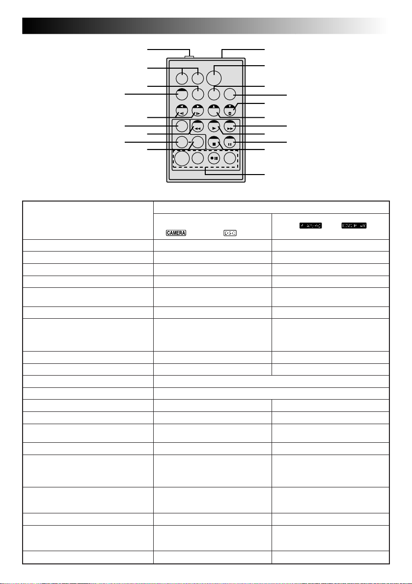
EN81
4
6
8
RM-V713U
(provided)
Buttons
1 PAUSE IN Connector
2 Zoom (T/W) Buttons
3 DISPLAY Button
4 SHIFT Button
5 SLOW Rewind/Forward Buttons
Left/Right Buttons
6 FADE/WIPE Button
7 REW Button
8 EFFECT Button
9 EFFECT ON/OFF Button
0 Infrared beam transmitting window
! START/STOP Button
@ AUDIO MONITOR Button
# MBR SET Button
$ Down Button
A.DUB Button
% Up Button
^ FF Button
& PLAY Button
* PAUSE Button
( STOP Button
) R.A.EDIT Buttons
1
2
TW
3
0
!
@
$
5
%
7 &
9 (
)
Functions
With the camcorder’s Power
Switch set to the camera position
(“ ”, “5S” or “ ”) .
—
Zoom in/out (Z pg. 24)
—
—
—
—
—
—
—
—
Transmits the beam signal.
Functions same as START/STOP on the camcorder.
—
—
—
—
—
—
—
—
—
—
#
^
*
With the camcorder’s Power Switch
set to “
Z pg. 85
Zoom in/out (
Z pg. 74
Z pg. 82
Z pg. 82
Z pg. 82
Z pg. 85
• Rewind/Reverse Shuttle Search on
a tape (Z pg. 52, 53)
•Displays previous image in a
MultiMediaCard (
Z pg. 83
Z pg. 83
Z pg. 55
Z pg. 84
Z pg. 82
Z pg. 90
Z pg. 82
• Forward/Forward Shuttle Search
on a tape (Z pg. 52, 53)
• Displays next image in a
MultiMediaCard (
• Starts Playback of a tape (
• Starts Auto Playback of a
MultiMediaCard (
Pauses the tape (
• Stops the tape (
• Stops Auto Playback or Slide Show
Z pg. 56, 57)
(
Z pg. 84 – 89
” or “ ”.
Z pg. 82)
Z pg. 56)
Z pg. 56)
Z pg. 52)
Z pg. 56)
Z pg. 53)
Z pg. 52)
Page 82
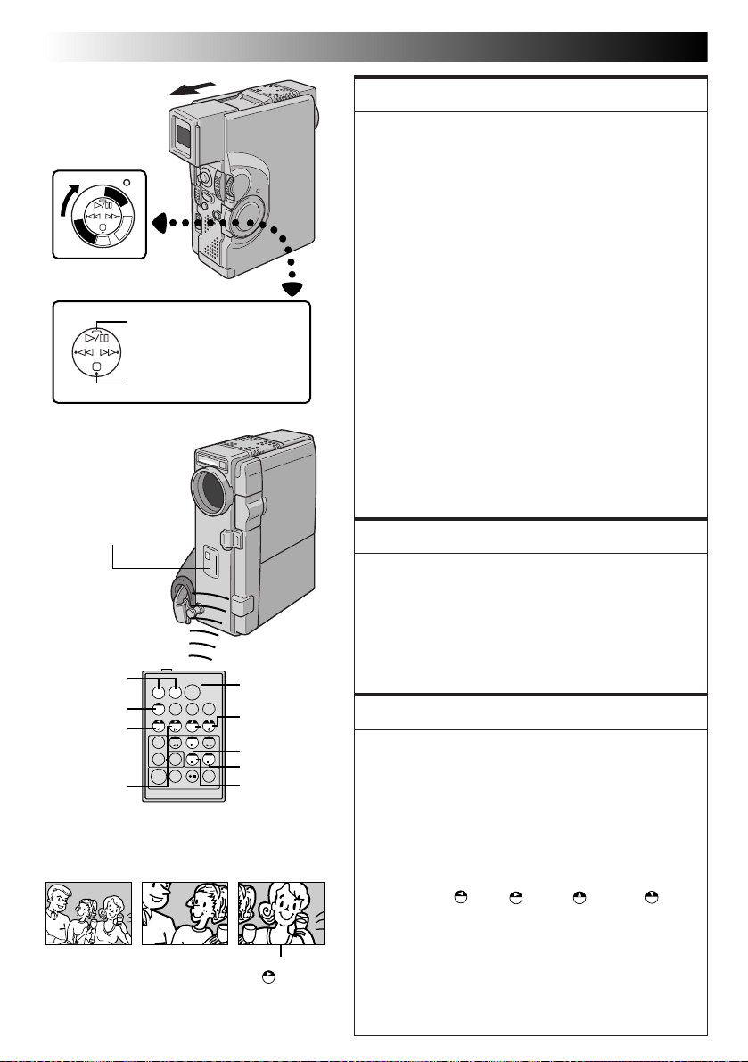
82 EN
USING THE REMOTE CONTROL UNIT
(cont.)
Power Switch
P
L
A
Y
A
L
P
C
S
S
D
D
S
C
Remote sensor
Zoom Buttons
SHIFT
Left or SLOW
Rewind Button
Right or SLOW
Forward Button
Y
/
P
C
O
F
F
C
A
M
E
R
A
5
Play (4) Button
Stop (5) Button
TW
RM-V713U
(provided)
Press TNormal playback
Up Button
Down Button
PLAY
PAUSE
STOP
To move image,
(Right)
press
while keeping
SHIFT held down.
FEATURE:
Slow-Motion Playback
PURPOSE:
To allow slow-speed search in either direction during
video playback.
OPERATION:
1) To change from normal to Slow-Motion Playback, press
PAUSE (6) at the point where you want to start
playback in slow motion.
2) Press SLOW (9 or 0). After playing back for approx.
1 minute in Slow Rewind or approx. 2 minutes in Slow
Forward, normal playback resumes.
n To stop Slow-Motion Playback in progess, press PLAY (4).
NOTES:
●
During Slow-Motion Playback, due to digital image
processing, the picture may take on a mosaic effect.
●
After SLOW
displayed for a few seconds, then the screen may become
blue back for a few seconds. This is not a malfunction.
●
There may be a small margin between the slow-motion
playback start point you chose and the start point at which
the camcorder actually begins playback in slow motion.
●
During Slow-Motion Playback, there will be disturbances in video and the picture may seem unstable,
especially with steady images. This is not a malfunc-
(9 or 0)
is pressed, the still image may be
tion.
●
During Slow-Motion Playback, press PAUSE
pause playback.
FEATURE:
Frame-By-Frame Playback
(6)
to
PURPOSE:
To allow frame-by-frame search during video playback.
OPERATION:
1) To change from normal to Frame-By-Frame Playback,
press PAUSE (6) at the point where you want to start
Frame-By-Frame Playback.
2) Press PAUSE (6) repeatedly. Each time it is pressed, the
frame is played back.
FEATURE:
Playback Zoom
PURPOSE:
To magnify the recorded image up to 10X at any time
during video playback.
OPERATION:
1) Press PLAY (4) to find the scene of interest.
2) Press the Zoom Buttons (T/W) on the remote control.
Make sure the remote control is pointed at the
camcorder's remote sensor. Pressing T zooms in.
3) You can move the image on screen around to find a
particular portion of the picture. While holding down
SHIFT, press (Left), (Right), (Up) and
(Down).
n To end zoom, press and hold W until magnification returns
to normal. Or, press STOP (5) and then press PLAY (4).
NOTES:
●
Zoom can also be used during slow-motion and still
playback.
●
During digital image processing, the quality of the
image may suffer.
Page 83
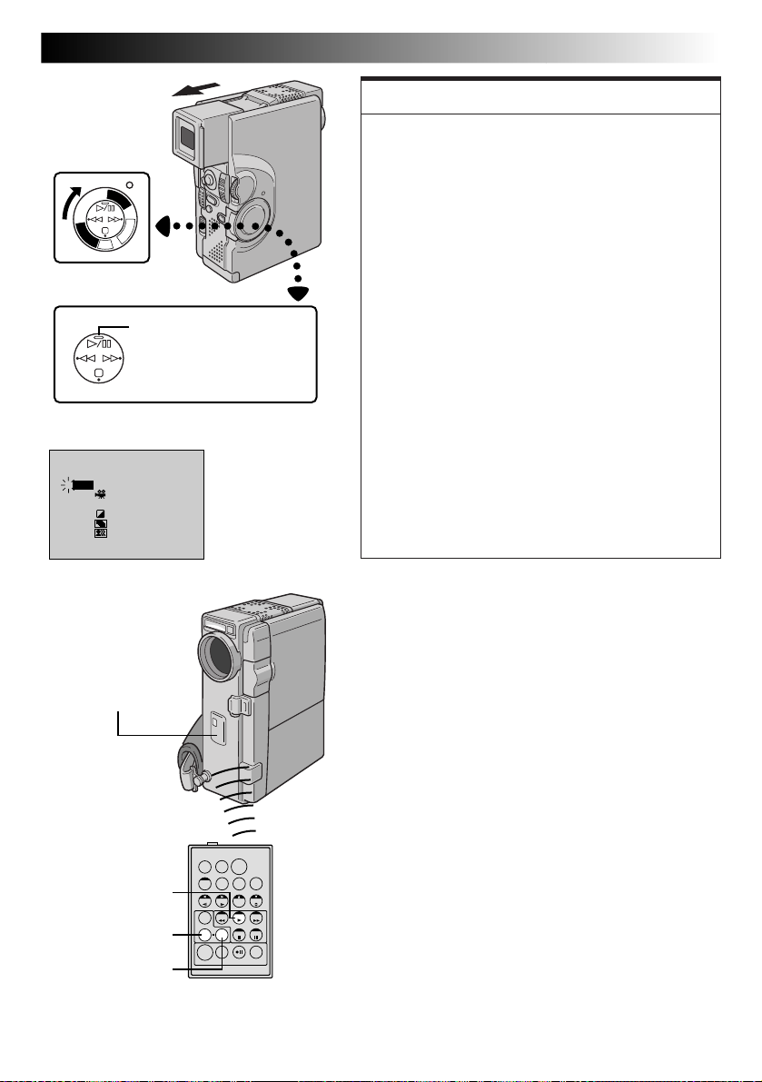
EN83
Power Switch
P
L
A
Y
/
P
C
O
F
F
C
A
Y
M
A
E
L
R
P
A
C
5
S
S
D
D
S
C
PLAYBACK EFFECT
4
OFF
CLASSIC FILM
1
B/W
MONOTONE
2
SEPIA
3
STROBE
4
VIDEO ECHO5
Play (
4
) Button
PLAYBACK EFFECT
Select Menu
FEATURE:
Playback Special Effects
PURPOSE:
To allow you to add creative effects to the video
playback image. You can use any one of the 5 effects.
OPERATION:
1) To start playback, press PLAY (4).
2) Point the remote control at the camcorder's remote
sensor and press EFFECT. The PLAYBACK EFFECT
Select Menu appears.
3) Move the highlight bar to the desired effect by
pressing EFFECT. The selected function is activated
and after 2 seconds the menu disappears.
n To deactivate the selected effect, press EFFECT ON/
OFF on the remote control. Pressing it again re-
activates the selected effect.
n To change the selected effect, repeat from step 2 of
the above “OPERATION”.
NOTES:
●
When some Playback Special Effects are used, the
Multi-Analyser 4 and Multi-Analyser 9 Snapshot
modes (Z pg. 31) are not available.
●
The effects that can be used during playback are
Classic Film, Monotone, Sepia, Strobe and Video
Echo. The effects work the same in playback as they
did in recording. Refer to page 45 for more
information.
Remote sensor
PLAY
EFFECT
EFFECT ON/OFF
TW
RM-V713U
(provided)
Page 84
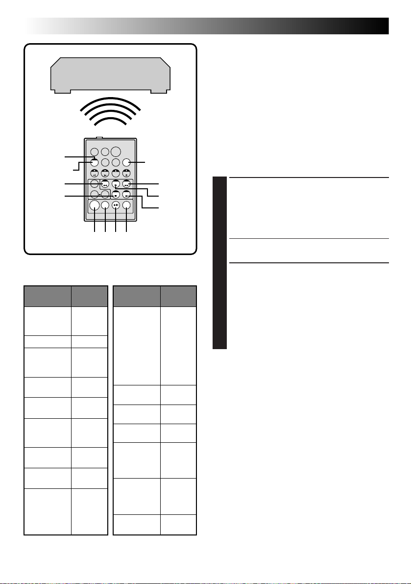
84 EN
3
SHIFT
1
6
RM-V713U
(provided)
VCR CODE LIST
VCR BRAND
NAME
AKAI
BLAUPUNKT
FERGUSON
GRUNDIG 1 4
HITACHI 6 6
JVC 9 1
A
B
C
MITSUBISHI 6 7
NEC 3 7
PANASONIC 1 3
USING THE REMOTE CONTROL UNIT
VCR (Recording deck)
TW
789`
BUTTONS
(A) (B)
6 2
6 4
7 7
1 3
9 7
9 8
3 2
3 4
6 3
9 6
9 3
6 8
3 8
1 7
1 1
9 4
1 8
VCR BRAND
NAME
PHILIPS
SANYO 3 6
SELECO,
REX
SHARP 1 5
SONY
THOMSON,
TELEFUNKEN,
SABA,
NORDMENDE
TOSHIBA 6 9
MBR SET
2
4
5
BUTTONS
(A) (B)
1 9
9 5
1 1
9 4
9 1
9 6
1 2
3 3
7 2
3 5
9 1
9 6
1 `
6 5
6 `
3 9
3 1
9 1
9 6
9 7
3 2
6 1
(cont.)
Random Assemble Editing [R.A.Edit]
Create edited videos easily using your camcorder as
the source player. You can select up to 8 “cuts” for
automatic editing, in any order you like. R.A.Edit is
more easily performed when the RM-V713U MBR
(Multi-Brand Remote, Z pg. 81) is set to operate
with your brand of VCR (see VCR CODE LIST), but
can also be performed by operating the VCR
manually.
Before operation, make sure the lithium battery is
installed in the remote control RM-V713U
(Z pg. 80).
SET REMOTE/VCR CODE
SET REMOTE TO OPERATE VCR
1
Turn off the power to the VCR and point the
remote towards the VCR’s infrared sensor. Then,
referring to the VCR CODE LIST on the left,
press and hold MBR SET, and press button (A)
and then (B).
•The code is automatically set once you release
MBR SET, and the VCR’s power comes on.
OPERATE VCR
2
Make sure the VCR’s power is on. Then, while
holding SHIFT, press the button on the remote
for the desired function. The functions the
remote can control are PLAY, STOP, PAUSE, FF,
REW and VCR REC STBY (you do not need to
press SHIFT for this one).
You are now ready to try Random Assemble
Editing.
IMPORTANT
Although the MBR is compatible with JVC VCRs and
those of many other makers, it may not work with
yours or may offer limited functions.
NOTES:
●
If the VCR’s power does not come on in step 1, try
another code from the VCR CODE LIST.
●
Some brands of VCR do not come on
automatically. In this case, turn the power on
manually and try step 2.
●
If the remote control is not able to control the VCR,
use the controls on the VCR.
●
When the remote control's battery runs out, the
VCR brand you have set will be erased.
In that case, replace the old battery with a new one
to reset the VCR brand.
Page 85
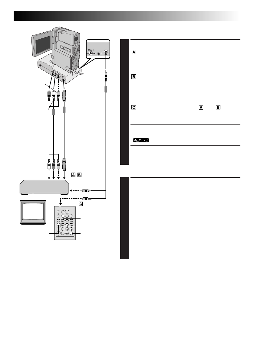
Yellow to
VIDEO OUT*
Red to AUDIO
R OUT
White to
AUDIO L OUT
A/V cable [RCA
plug to RCA plug]
(provided)
To AUDIO,
VIDEO*
and S-VIDEO
IN connectors
VCR
TV
FADE/WIPE
* Connect when the S-Video cable is not used.
To
S-VIDEO
OUT
S-Video cable
(provided)
TW
RM-V713U
(provided)
Editing cable
(provided)
To Remote PAUSE
or R.A.EDIT
To PAUSE IN
DISPLAY
PLAY
R.A.EDIT
ON/OFF
To
EDIT
MAKE CONNECTIONS
Also refer to pg. 70, 71 and 73.
CONNECT TO . . .
1
JVC VCR EQUIPPED WITH REMOTE PAUSE
TERMINAL
Connect the editing cable to the Remote PAUSE
terminal.
JVC VCR NOT EQUIPPED WITH REMOTE
PAUSE TERMINAL BUT EQUIPPED WITH
R.A.EDIT CONNECTOR
Connect the editing cable to the R.A.EDIT
connector.
VCR OTHER THAN TYPE OR
Connect the editing cable to the RM-V713U’s
PAUSE IN connector.
PREPARE CAMCORDER
2
Insert a recorded tape and set the Power Switch to
“ ” while pressing down the Lock Button.
PREPARE VCR
3
Turn the power on, insert a recordable tape and
engage the AUX mode (refer to VCR’s instructions).
SELECT SCENES
START SOURCE PLAYBACK
4
Press PLAY (4) and then press R.A.EDIT ON/OFF on
the remote control. Make sure to point the remote
control at the camcorder’s remote sensor.
•The Random Assemble Editing Menu appears.
EXECUTE FADE/WIPE IN
5
(IF NECESSARY)
Press FADE/WIPE on the remote control.
•Cycle through the effects by pressing repeatedly,
and stop when the one you want is displayed.
•You cannot use a Picture Wipe/Dissolve at the
beginning of Programme 1.
EN85
NOTES:
●
You can use the AV OUT connector on the camcorder for connection.
●
Before Random Assemble Editing, make sure the indications do not appear on the TV monitor. If they appear
during Random Assemble Editing, they will be recorded onto the new tape. To clear the Playback Sound
Mode Display, press DISPLAY on the remote control. Select “DISPLAY” and “TIME CODE” from the Playback
Menu (Z pg. 54) to show or hide the Date/Time and the Time Code on the recording. To show or hide all
indications except for the Random Assemble Editing Menu, set “INDICATION” to “OFF” in the Playback
Menu (Z pg. 54) and press DISPLAY on the remote control. When Random Assemble Editing starts, its
indications disappear and are not recorded on the new tape.
●
When editing on a VCR equipped with DV input connector, the DV cable can be connected instead of the SVideo cable and Audio/Video cable.
CONTINUED ON NEXT PAGE
Page 86
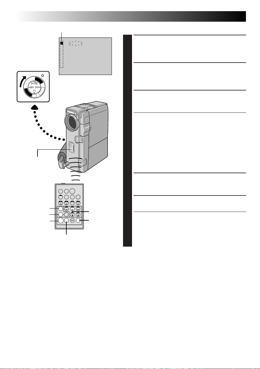
86 EN
Power Switch
Y
A
L
P
C
S
D
Remote sensor
RM-V713U
(provided)
FADE/WIPE
EDIT IN/OUT
P
L
A
Y
/
P
A
5
S
D
S
C
EFFECT
USING THE REMOTE CONTROL UNIT
Programme
I N OUT MODE
1 –– – – : –– ~
2
3
4
5
6
7
8
C
O
F
F
C
A
M
E
R
~
~
~
~
~
~
TIME CODE
–– : ––
00 : 00
TOTAL
Random Assemble
Editing Menu
4
SELECT SCENES (cont.)
SET EDIT-IN POINT
6
At the beginning of the scene, press EDIT IN/OUT on
the remote control. The Edit-In position appears on
the Random Assemble Editing Menu.
SET EDIT-OUT POINT
7
At the end of the scene, press EDIT IN/OUT. The
Edit-Out position appears on the Random Assemble
Editing Menu.
USE FADE/WIPE ON SCENE
8
TRANSITION (IF NECESSARY)
(cont.)
Press FADE/WIPE.
•Cycle through the effects by pressing repeatedly,
and stop when the one you want is displayed.
•If you select a Fade/Wipe effect for an Edit-Out
point, the effect is automatically applied to the
following Edit-In point.
•You cannot use a Picture Wipe/Dissolve at the end
of the last scene.
•When you use Fade/Wipe effects, that time is
included in the total time (this does not apply to
TW
CANCEL
PLAY
R.A.EDIT
ON/OFF
Picture Wipe/Dissolve).
USE PLAYBACK SPECIAL EFFECTS
9
(IF NECESSARY,
Press EFFECT.
REGISTER ADDITIONAL SCENES
10
Repeat steps 6 through 9.
•To change previously registered points, press
CANCEL on the remote control. The registered
points disappear, one at a time, from the most
recently registered point.
•If you are not using Fade/Wipe or Programme AE
1
Z pg. 83)
with special effects, repeat steps 6 and 7 only.
NOTES:
●
When the source tape has more than 2 identical time codes (Z pg. 25), the camcorder may not find the
Edit-In point you chose and a malfunction may occur.
●
When choosing a scene, set Edit-In and Edit-Out points so that there is a relatively large difference between
them.
●
If the search time for an in-point exceeds 5 minutes, the recording deck’s Record-Standby mode will be
cancelled and editing will not take place.
●
If there are blank portions before or after the Edit-In and Edit-Out points, a blue-backed screen may be
included in the edited version.
●
Since time codes register time only as accurately as seconds, the time code total time may not match the
total programme time exactly.
●
Turning off the camcorder’s power erases all registered Edit-In and Edit-Out points.
●
If you select Sepia or Monotone mode from Programme AE with special effects, you cannot use the Dissolve
or Black & White Fader. In this case the Dissolve or Black & White indicator begins blinking. Once the next
Edit-In point is registered, the effect is turned off. To combine these effects, use Sepia or Monotone during
recording, then use Dissolve or Black & White Fader during Random Assemble Editing.
●
It is not possible to use Fade/Wipe effects and Programme AE with special effects during Random Assemble
Editing using a DV cable.
Page 87
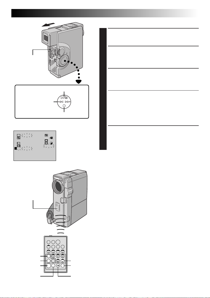
START/STOP
Button
2
~
~
~
16 : 30
9 : 39
) Button
Stop (5) Button
P
Rewind (
I N OUT MODE
W
H
1 00 : 2 5 ~ 02 : 05 ––
2 07 : 1 8 ~ 08 : 31––
P
3 –– 03 : 33 ~ 05 : 5 3
4 09 : 3 0 ~ 13 : 1 5
5 15 : 5 5 ~ 16 : 20–– ––
6 –– –– : ––
7
8
TIME CODE
TOTAL
Remote Sensor
Pause (6) Button
Random Assemble
Editing Menu
B/W
4
EN87
AUTOMATIC EDITING TO VCR
PREPARE SOURCE TAPE
11
Rewind the tape in the camcorder to the beginning of
the scene you want to edit and press PAUSE (6).
ENGAGE VCR'S RECORD-PAUSE MODE
12
Point the remote control towards the VCR’s remote
sensor and press VCR REC STBY (q6), or manually
engage the VCR’s Record-Pause mode.
START EDITING
13
Press START/STOP on the camcorder. Editing
proceeds as programmed, right through to the end of
the last registered scene.
•Pressing START/STOP on the remote control does
not start editing.
•When dubbing is complete, the camcorder enters
the Pause mode, and the recording deck enters its
Record-Standby mode.
•If you do not register an Edit-Out point, the tape will
be dubbed all the way to the end automatically.
STOP EDITING
14
Engage the Stop modes for the camcorder and the
VCR.
To make the R.A.Edit counter display disappear, press
R.A.EDIT ON/OFF on the remote control.
NOTES:
●
Pressing R.A.EDIT ON/OFF on the remote control clears
all settings registered during Random Assemble Editing.
●
When the editing cable is connected to the Pause
terminal during dubbing, make sure the remote control
is pointed at the VCR’s sensor, and that the path between
the two is unobstructed.
●
Random Assemble Editing may not function properly
when using a tape including several duplicated Time
Codes (Z pg. 25).
1
RM-V713U
(provided)
FADE/WIPE
EFFECT
EDIT IN/OUT
CANCEL
TW
PAUSE
R.A.EDIT
ON/OFF
VCR REC
STBY
Page 88
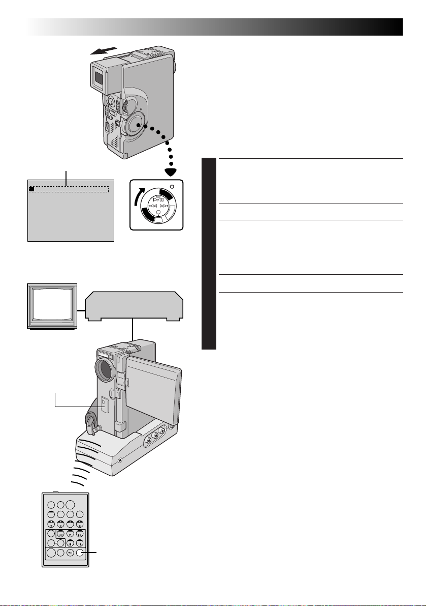
88 EN
Programme 1
I N OUT MODE
1 –– – – : –– ~
2
3
4
5
6
7
8
TIME CODE
TOTAL
Random Assemble
Editing Menu
TV
~
~
~
~
~
~
~
–– : ––
00 : 00
USING THE REMOTE CONTROL UNIT
For More Accurate Editing
Some VCRs make the transition from Record-Standby to
Record mode faster than others. Even if you begin editing
for the camcorder and the VCR at exactly the same time,
you may lose scenes you wanted, or find that you have
recorded scenes you did not want. For a cleanly edited
tape, confirm and adjust the timing of the camcorder
against your VCR.
DIAGNOSING VCR’S AGAINST
CAMCORDER TIMING
PREPARE FOR R.A.EDIT
1
Play back the tape in the camcorder, then point the
remote control at the camcorder’s remote sensor and
press R.A.EDIT ON/OFF.
•“Random Assemble Editing Menu” appears.
CHOOSE A SCENE
2
Perform Random Assemble Editing on Programme 1
only. In order to check VCR and camcorder timing,
select the beginning of a scene transition as your EditIn point.
PLAY BACK DUBBED SCENE
3
•If any images from the scene prior to the transition
you chose for your Edit-In point were recorded, that
means your VCR moves quickly from Record-Pause
to Record mode.
•If the scene you tried to dub starts in progress, the
VCR is slow to start recording.
Y
A
4
Power Switch
VCR
(Recording deck)
P
L
A
Y
/
P
C
O
F
F
C
A
M
E
L
R
P
A
C
5
S
S
D
D
S
C
(cont.)
Remote sensor
TW
RM-V713U
(provided)
R.A.EDIT
ON/OFF
Page 89
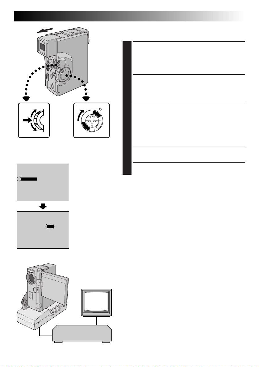
ADJUSTMENT OF VCR’S AGAINST
CAMCORDER TIMING
ACCESS PLAYBACK MENU
4
Point the remote control at the camcorder’s remote
sensor and press R.A.EDIT ON/OFF to make the
Random Assemble Editing menu disappear, then
press MENU/SET. The Playback Menu appears.
SELECT FUNCTION
5
Move the highlight bar to “SYNCHRO” by rotating
MENU/SET, then press it. The value for “SYNCHRO”
is highlighted.
EN89
MENU/SET Dial
Display
32kHz MODE
4
SYNCHRO
INDICATION
DISPLAY
TIMECODE
END
32kHz MODE
4
SYNCHRO
INDICATION
DISPLAY
TIMECODE
END
FULL SOUND48kHz MODE
SOUND1
0 . 0
ON
ON
OFF
FULL SOUND48kHz MODE
SOUND1
0 . 0
ON
ON
OFF
P
L
A
Y
A
L
P
C
S
S
D
D
S
C
Power Switch
Playback Menu
INPUT CORRECTION DATA
Y
/
P
C
O
F
F
C
A
M
E
R
A
5
6
Based on the diagnostics performed (Z pg. 88), you
can now increase the VCR’s speed by rotating
MENU/SET upward. You can also slow down the
VCR’s speed by rotating MENU/SET downward. The
adjustment range is from –1.3 to +1.3 seconds, in
0.1-second increments.
CLOSE MENU
7
Press MENU/SET twice.
•Now perform Random Assemble Editing beginning
with step 4 on page 85.
NOTES:
●
Before performing actual Random Assemble Editing, do
a few Random Assemble Editing trial runs to check
whether the value you have input is appropriate or not,
and make adjustments accordingly.
●
Depending on the recorder, there may be situations
where the timing difference cannot be fully corrected.
TV
VCR
(Recording deck)
Page 90

90 EN
Lock Button
Speaker
Display
Audio Dub Standby mode Power Switch
Remote sensor
AV OUT
(headphones)
connector
Located
beneath
the cover.
AUDIO
MONITOR
DISPLAY
PLAY
RM-V713U
(provided)
USING THE REMOTE CONTROL UNIT
Stereo microphone
TW
P
L
A
Y
/
P
C
O
F
F
C
A
Y
M
A
E
L
R
P
A
C
5
S
S
D
D
S
C
External
microphone
input connector
A.DUB
PAUSE
STOP
(cont.)
Audio Dubbing
The audio track can be customized only when recorded
on the 32 kHz mode (Z pg. 39).
NOTES:
●
Audio Dubbing is not possible on a tape recorded at
48 kHz, on a tape recorded in the LP mode or on a
blank portion of a tape.
●
To perform Audio Dubbing while watching in the
television, make connections (Z pg. 70).
FIND EDIT-IN POINT
1
Play back the tape to locate the point where editing
will start, then press PAUSE (6).
ENGAGE AUDIO DUB STANDBY
2
While holding A.DUB (e) on the remote control,
press PAUSE (6). “6e” appears.
BEGIN DUBBING
3
Press PLAY (4) , then begin “narrating”.
•Speak into the microphone.
PAUSE DURING DUBBING
4
Press PAUSE (6).
STOP DUBBING
5
Press STOP (5).
NOTES:
●
Audio dubbing is also possible using an optional
microphone.
●
While an optional microphone is connected, the built-in
microphone is disabled.
●
When editing onto a tape that was recorded at 32 kHz,
the old and new soundtracks are recorded separately.
●
To select the desired sound for playback, press AUDIO
MONITOR on the remote control.
●
If you dub onto a blank space on the tape, the sound may
be disrupted. Make sure you only edit recorded areas.
●
If feedback or howling occurs during TV Playback, move
the camcorder’s microphone away from the TV, or turn
down the TV’s volume.
●
Sound is not heard from the speaker during Audio
Dubbing. To hear sound, connect optional headphones
to the AV OUT (headphones) connector.
●
If you change from 32 kHz to 48 kHz in mid-recording
and then use the tape for Audio Dubbing, it is not
effective from the point where 48 kHz recording began.
●
During Audio Dubbing, when the tape moves to scenes
recorded in the LP mode, scenes recorded at 48 kHz or
a blank portion, Audio Dubbing stops and “ERROR!
REFER MANUAL” appears.
Recording sound Display Output sound
FULL SOUND Original and new tracks are combined and output in stereo.
32 kHz SOUND 2 New track is output on both “L” and “R” channels in stereo.
SOUND 1 Original track is output on both “L” and “R” channels in stereo.
Page 91
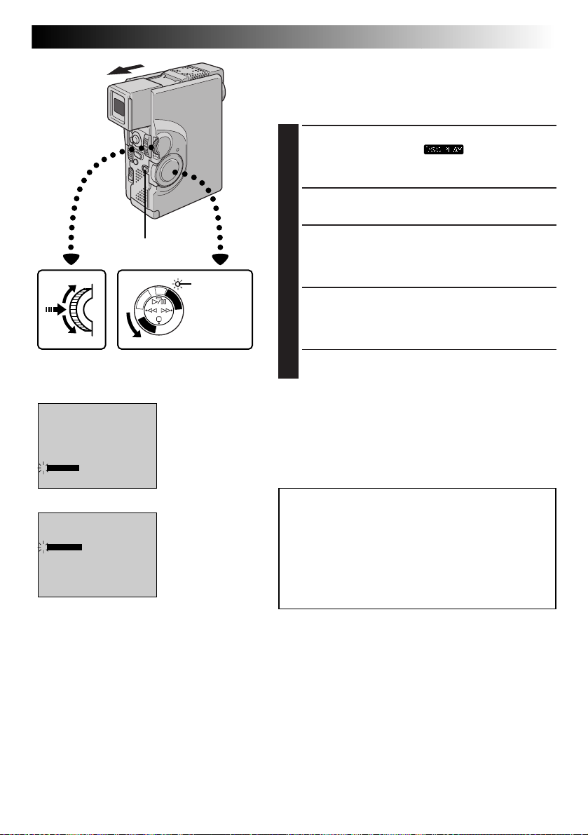
ADDITIONAL INFORMATION
Initializing A MultiMediaCard
If the MultiMediaCard’s memory is corrupt, “PLEASE
INITIALIZE” will appear. In this case, you will have to
initialise the MultiMediaCard.
1
2
EN91
SELECT OPERATION MODE
Set the Power Switch to “ ”, while pressing
down the Lock Button. Open the LCD monitor fully
or pull out the viewfinder fully.
ACCESS PLAYBACK MENU
Press MENU/SET. The Playback Menu appears.
MENU/SET Dial
Display
INDEX
SLIDE SHOW
MULTI VIEW
PROTECT
FILE DELETE
TITLE DELETE
4
FORMAT
END
4
EXECUTE
CANCEL
Lock Button
OFF
OFFIrTran-P
Power Lamp
S
C
D
S
D
5
S
A
C
R
P
E
L
M
A
A
Y
C
F
F
O
C
P
/
Y
A
L
P
Power Switch
Playback Menu
Format Confirmation
Screen
SELECT FUNCTION
3
Rotate MENU/SET to move the highlight bar to
“FORMAT” and press it. The Format Confirmation
Screen appears.
INITIALIZE MULTIMEDIACARD
4
Rotate MENU/SET to move the highlight bar to
“EXECUTE” and press it. The MultiMediaCard is
initialised.
•If you wish to cancel initialization, rotate MENU/
SET to select “CANCEL” and press it.
NOTES:
●
After initializing, all images stored in the
MultiMediaCard, including those which have been
protected, are cleared.
●
Initialization is possible only when “PLEASE INITIALIZE”
appears.
CAUTION:
Do not perform any other operation (such as
turning off the camcorder) during initialization.
Also, be sure to use the provided AC Power
Adapter/Charger, as the MultiMediaCard may be
corrupted if the battery becomes exhausted
during initialization.
Page 92

92 EN
TROUBLESHOOTING
If, after following the steps in the chart below, the problem still exists, please consult your nearest JVC dealer.
The camcorder is a microcomputer-controlled device. External noise and interference (from a TV, a radio,
etc.) might prevent it from functioning properly. In such cases, first disconnect its power supply unit (battery
pack, AC Power Adapter/Battery Charger, etc.) and wait a few minutes; and then re-connect it and proceed
as usual from the beginning.
SYMPTOM POSSIBLE CAUSES CORRECTIVE ACTION
1.
No power is supplied.
2.
“SET DATE/TIME!” appears.
3.
Recording cannot be
performed.
4.
There is no picture.
5.
Some functions are not
available using MENU/SET.
6.
The focus does not adjust
automatically.
7.
The cassette will not load
properly.
8.
The MultiMediaCard will not
load properly.
9.
In the 5-Second mode,
recording ends before
5 seconds have elapsed.
1.
• The power is not connected
properly.
• The battery is dead.
• The LCD monitor is not open
fully or the viewfinder is not
pulled out when recording.
2.
• The built-in clock’s rechargeable lithium battery is
discharged.
• The previously set date/time is
erased.
3.
• The tape’s erase protection
switch is set to “SAVE”.
• The Power Switch is set to
“ ”.
• “TAPE END” appears.
• The cassette’s cover is open.
4.
• The camcorder is not getting
power, or some other
malfunction exists.
5.
• The Operation Switch is set to
“ ”.
6.
• Focus is set to “MANUAL”.
• The recording was done in a
dark place, or the contrast
was low.
• The lens is dirty or covered
with condensation.
7.
• The cassette is in the wrong
position.
• The battery’s charge is low.
8.
• The MultiMediaCard is in the
wrong position.
9.
• The 5-Second mode in the
System Menu is set to
“ANIM.”.
1.
• Connect the AC Power
Adapter/Charger securely
(Z pg. 9).
• Replace the dead battery with a
fully charged one (Z pg. 8, 9).
• Open the LCD monitor fully
or pull out the viewfinder. The
LCD monitor turns on/off
when it is opened/closed at
approx. 90° while the Power
Switch is set to any position
except “OFF” if the viewfinder
is not fully pulled out.
2.
• Connect the camcorder to an
AC outlet using the AC Power
Adapter/Charger for over 24
hours to charge the clock’s
lithium battery (Z pg. 11).
3.
• Set the tape’s erase protection
switch to “REC” (Z pg. 12).
• Set the Power Switch to any
position except “ ” or
“OFF” (Z pg. 17).
• Replace with new cassette
(Z pg. 12).
• Close the cassette’s cover.
4.
• Turn the camcorder’s power
off and on again (Z pg. 18).
5.
• Set the Operation Switch to
“ ” (Z pg. 17).
6.
• Set Focus to “AUTO”
(Z pg. 47).
• Clean the lens and check the
focus again (Z pg. 98).
7.
• Set it in the right position
(Z pg. 12).
• Install a fully charged battery
(Z pg. 8, 9).
8.
• Set it in the right position
(Z pg. 14).
9.
• Select “5S” or “5SD” in the
System Menu (Z pg. 34 –
39).
Page 93

SYMPTOM POSSIBLE CAUSES CORRECTIVE ACTION
10.
Snapshot mode cannot be
used.
11.
Although Snapshot is
attempted, flash does not
take place.
12.
Although Snapshot is taken
with the flash, Red-Eye
Reduction does not take
place.
13.
The image taken using
Snapshot is too dark.
14.
The image taken using
Snapshot is too bright.
15.
The colour of Snapshot looks
strange.
16.
Digital Zoom does not work.
10.
•
The Squeeze mode is selected.
11.
• The subject is too bright with
the flash set to “AUTO” or
“AUTO ”.
• If blinks, the flash is being
charged.
• Multi-Analyser 4 or MultiAnalyser 9 is selected.
• The camcorder is in the
Record mode.
12.
• The subject does not look
straight toward the flash.
• The subject does not look at
the first flash, which is an
important part of Red-Eye
Reduction.
• The camcorder is too far from
the subject.
• “FLASH” is not set to “AUTO
” in the Mode Menu.
13.
• “FLASH” is set to “OFF” in the
Mode Menu.
• The flash emission window is
covered by fingers, etc..
• The flash brightness is set to
produce a darker image
(adjustment value: –3).
• The camcorder is too far from
the subject.
14.
• “FLASH” is set to “ON” in the
Mode Menu.
15.
• The light source or the subject
does not include white. Or
there are various different
light sources behind the
subject.
16.
• 10X optical zoom is selected.
• The Video Echo mode is
activated.
• Picture Wipe or Dissolve are
being used in a scene
transition.
• 5-Second recording was
done with the Power Switch
set to “5S”, and with “5SD”
selected in the System Menu.
10.
• Disengage the Squeeze mode
(Z pg. 37).
11.
• Set “FLASH” to “ON” in the
Mode Menu (Z pg. 32).
• It can take up to 10 seconds
to charge the flash.
•
Disengage Multi-Analyser 4 or
Multi-Analyser 9 (Z pg. 23, 31).
• Set the camcorder in the
Record-Standby mode
(Z pg. 32).
12.
• The subject should look
straight toward the flash,
especially the first flash. If the
subject does not see the first
flash, it will be difficult for
Red-Eye Reduction to take
place (Z pg. 32).
• The flash is effective for
subjects at a distance of
approx. 0.7 m to 2 m from the
camcorder (Z pg. 32).
• Set “FLASH” to “AUTO ”
in the Mode Menu to display
the Red-Eye Reduction
indicator (Z pg. 32).
13.
• Set “FLASH” to any position
except “OFF” in the Mode
Menu (Z pg. 32).
• Do not cover the flash
emission window.
• Adjust the flash brightness to a
larger value (Z pg. 33).
• The flash is effective for
subjects at a distance of
approx. 0.7 m to 2 m
(Z pg. 32).
14.
• Set “FLASH” to any parameter
other than “ON” in the Mode
Menu (Z pg. 32).
15.
• Set “FLASH” to “ON” in the
Mode Menu. Or find a white
subject and compose your
shot so that it also appears in
the frame (Z pg. 32).
16.
• Turn off the Video Echo mode
(Z pg. 45).
• Wait until the Picture Wipe or
Dissolve effects are completed
(Z pg. 41 – 43).
• Change the setting of either
the System Menu or the
Power Switch (Z pg. 28).
EN93
CONTINUED ON NEXT PAGE
Page 94

94 EN
SYMPTOM POSSIBLE CAUSES CORRECTIVE ACTION
17.
Programme AE with special
effects and Fade/Wipe Effects
do not work.
18.
The Black & White Fader
does not work.
19.
The Dissolve function does
not work.
20.
The Picture Wipe and
Dissolve functions do not
work.
21.
The picture wipe function
doesn’t work.
22.
Scene transition does not go
as expected.
TROUBLESHOOTING
17.
• The Operation Switch is set to
“ ” and/or the Power Switch
is set to “5S”.
18.
• The Sepia or Monotone mode
is activated.
19.
• The Sepia, Monotone or Slow
Shutter mode of Programme
AE with special effects is
activated.
• The Squeeze mode is
selected.
• The previously selected mode
of Programme AE with special
effects was changed after the
last selected scene for editing
was registered.
20.
• The last selected editing scene
is ending.
• At the end of the last selected
scene for editing, the Power
Switch was set to “OFF”.
• The power is off.
21.
• The Slow Shutter mode is
activated.
• The Squeeze or Cinema mode
is selected in the Mode Menu.
22.
• When using “Picture Wipe/
Dissolve” (Z pg. 42) or
“Dissolves during 5 second
recording mode” (Z pg. 28),
there is a delay of a fraction of
a second between the
previous record stop-point
and the Dissolve start-point.
This is normal, but this slight
delay becomes especially
noticeable when shooting
fast-moving subject or during
rapid panning.
(cont.)
17.
• Set the Operation Switch to
“ ” and/or set the Power
Switch to “ ” or
“ ”.
18.
• Turn off Sepia and Monotone
(Z pg. 44).
19.
• Turn off Sepia, Monotone or
Slow Shutter before adding
Dissolve to a scene transition
(Z pg. 44).
• Make sure that the Squeeze
mode in the Mode Menu is
set to “OFF” (Z pg. 37).
• Make sure you have selected
the mode of Programme AE
with special effects you want
before starting editing
(Z pg. 44).
20.
• Select Picture Wipe or
Dissolve before beginning
recording. The effects are then
automatically activated
(Z pg. 42).
• Do not turn off the
camcorder’s power after
setting Edit-In and Edit-Out
points, as they will all be
erased (Z pg. 42).
• The camcorder automatically
shuts off after 5 minutes have
elapsed in the RecordStandby mode. Make sure you
continue operations within
5 minutes after engaging
Record-Standby mode
(Z pg. 42).
21.
• Make sure the Squeeze mode,
Cinema mode, or Slow
Shutter mode is not activated
when preparing to use the
Picture Wipe function
(Z pg. 37, 45).
22.
————
Page 95

SYMPTOM POSSIBLE CAUSES CORRECTIVE ACTION
23.
The Video Echo mode does
not work.
24.
Even when Slow Shutter is
not selected, the image looks
like it is activated.
25.
There is no strobe when the
Classic Film or Strobe mode
is activated.
26.
White Balance cannot be
activated.
27.
When shooting a subject
illuminated by bright light,
vertical lines appear.
28.
When the screen is under
direct sunlight during
shooting, the screen becomes
red or black for an instant.
29.
During recording, the date/
time does not appear.
30.
Images stored in the
MultiMediaCard cannot be
deleted.
31.
The indicators and messages
do not appear.
32.
Images on the LCD monitor
appear dark or whitish.
23.
• The Picture Wipe or
Dissolve functions are in use.
• The Squeeze mode is selected
in the Mode Menu.
• A Fade-In or Fade-Out is in
progress.
• Dissolve during 5-second
mode recording is in use.
24.
•
When shooting in the dark, the
unit becomes highly sensitive to
light and the image takes on an
effect similar to Slow Shutter.
25.
• The Picture Wipe or Dissolve
function is in use.
• Dissolve during 5-second
mode recording is in use.
26.
• The Sepia or Monotone mode
is activated.
27.
• This is a result of exceedingly
high contrast, and is not a
malfunction.
28.
• This is not a malfunction.
29.
• “DISPLAY” is set to “OFF” in
the Date/Time Menu.
• Interface Shooting is
performed.
30.
• Images stored in the
MultiMediaCard are
protected.
31.
• “ON SCREEN” is set to “OFF”
in the Date/Time Menu.
• You have made the indicators
disappear.
32.
• In places subject to low
temperature, images become
dark due to the characteristics
of the LCD monitor. When
this happens, the displayed
colours differ from those that
are actually recorded. This is
not a defect of the camcorder.
•
When the LCD monitor’s
fluorescent light reaches the
end of its service life, images on
the LCD monitor become dark.
Consult your nearest JVC dealer.
23.
• Make sure the Squeeze mode
is set to “OFF” (Z pg. 34 –
39).
• Do not try to use the Video
Echo mode during a Fade-In or
Fade-Out or when Dissolve is
activated during 5-second
mode recording (Z pg. 44,
45).
24.
• If you want the lighting to
look more natural, set GAIN
UP to “AGC” or “OFF” in the
Mode Menu (Z pg. 34 – 39).
25.
• Do not try to use the Classic
Film or Strobe mode during a
scene transition (Z pg. 44,
45).
26.
• Turn off Sepia or Monotone
before setting White Balance
(Z pg. 44, 45).
27.
————
28.
————
29.
• Set “DISPLAY” to “ON” in the
Date/Time Menu (Z pg. 26).
• During Interface Shooting, the
date/time does not appear
(Z pg. 21).
• Set “INDICATION” to “ON”
in the Date/Time Menu
(Z pg. 27).
30.
• Remove protection from the
images stored in the
MultiMediaCard and delete
them (Z pg. 62, 64).
31.
• Set “ON SCREEN” to “ON” in
the Date/Time Menu
(Z pg. 26).
• Set “INDICATION” to “ON”
in the Date/Time Menu
(Z pg. 27).
32.
• Adjust the brightness and
angle of the LCD monitor
(Z pg. 21).
EN95
CONTINUED ON NEXT PAGE
Page 96
96 EN
SYMPTOM POSSIBLE CAUSES CORRECTIVE ACTION
33.
The rear of the LCD monitor
is hot.
34.
The indicators and the image
colour on the LCD monitor
are not clear.
35.
The LCD monitor or
viewfinder indications blink.
36.
Coloured bright spots appear
all over the LCD monitor or
the viewfinder.
37.
During recording, sound
cannot be heard.
38.
Play, Rewind and FastForward functions do not
work.
39.
The tape is moving, but
there is no picture.
40.
The LCD monitor indications
are distorted.
TROUBLESHOOTING
33.
• The light used to illuminate
the LCD monitor causes it to
become hot.
34.
• This may occur when the
surface or the edge of the LCD
monitor is pressed.
35.
• Certain Fade/Wipe effects,
certain modes of Programme
AE with special effects, “DIS”
and other functions that
cannot be used together are
selected at the same time.
36.
• The LCD monitor and the
viewfinder are made with
high-precision technology.
However, black spots or
bright spots of light (red, green
or blue) may appear
constantly on the LCD
monitor or the viewfinder.
These spots are not recorded
on the tape. This is not due to
any defect of the unit.
(Effective dots: more than
99.99 %)
37.
• The optional headphones are
not connected to the
headphones connector.
• The sound volume of the
headphones connector was
not adjusted appropriately.
The sound volume at this
point is the same as the level
it was adjusted to during
playback.
38.
• The Power Switch is not set to
“ ”.
39.
• Your TV has AV input
terminals, but is not set to its
VIDEO mode.
• The cassette’s cover is open.
40.
• During playback of the
unrecorded portion, Highspeed Search and still
playback, LCD monitor
indications appear distorted.
This is not a defect.
(cont.)
33.
• Close the LCD monitor to turn
it off or set the Power Switch
to “OFF”, and let the unit cool
down.
34.
————
35.
• Re-read the sections covering
Fade/Wipe effects, Programme AE with special
effects and “DIS” (Z pg. 37,
41 – 45).
36.
————
37.
• Connect the optional
headphones to the headphones connector
(Z pg. 100).
• Adjust the sound volume
during playback (Z pg. 52).
38.
• Set the Power Switch to
“ ” (Z pg. 52).
39.
• Set the TV to the mode or
channel appropriate for video
playback (Z pg. 70, 71).
• Close the cassette’s cover
(Z pg. 12).
40.
————
Page 97

SYMPTOM POSSIBLE CAUSES CORRECTIVE ACTION
41.
Images on the LCD monitor
are jittery.
42.
The LCD monitor, the
viewfinder and the lens have
become dirty (ex. fingerprints).
43.
An unusual mark appears.
44.
An error indication
(E01 — E06) appears.
45.
The charger indicator on the
AC Power Adapter/Charger
does not light.
46.
The recording mode
indicator “LP” blinks.
47.
Picture does not appear on
the LCD monitor.
48.
When the image is printed
from the printer, a black bar
appears at the bottom of the
screen.
49.
When the camcorder is
connected via the DV
connector, the camcorder
does not operate.
41.
• The speaker volume is too
great.
42.
————
43.
————
44.
• A malfunction of some kind
has occurred. In this case the
camcorder’s functions
become unusable.
45.
• The temperature of the battery
is extremely high/low.
• Charging is difficult in places
subject to extremely high/low
temperatures.
46.
• This occurs when recording in
the LP mode is not available.
After the indicator blinks, the
recording mode switches to
“SP” and recording goes on.
47.
• The viewfinder is pulled out.
• The LCD monitor's brightness
setting is too dark.
48.
• This is not a malfunction.
49.
• The DV cable was plugged/
unplugged with power turned
on.
41.
• Turn the speaker volume
down (Z pg. 52).
42.
• Wipe them gently with soft
cloth. Wiping strongly can
cause damage.
43.
• Check the section of the
manual that explains LCD
monitor/viewfinder
indications (Z pg. 102 –
105).
44.
• Remove the power supply
(battery pack, etc.) and wait a
few minutes for the indication
to clear. When it does, you
can resume using the
camcorder.
If the indication remains even
though you repeat the above
two or three times, please
consult your nearest JVC
dealer.
45.
• To protect the battery, it is
recommended to charge it in
places with a temperature of
10°C to 35°C (Z pg. 107).
46.
————
47.
• Push the viewfinder back in.
• Adjust the brightness of the
LCD monitor (Z pg. 21).
• If the monitor is tilted upward
180 degrees, open the
monitor fully (Z pg. 20).
48.
• By recording with “DIS”
activated (Z pg. 37) this can
be avoided.
49.
• Turn the camcorder’s power
off and on again, then operate
it.
EN97
Page 98
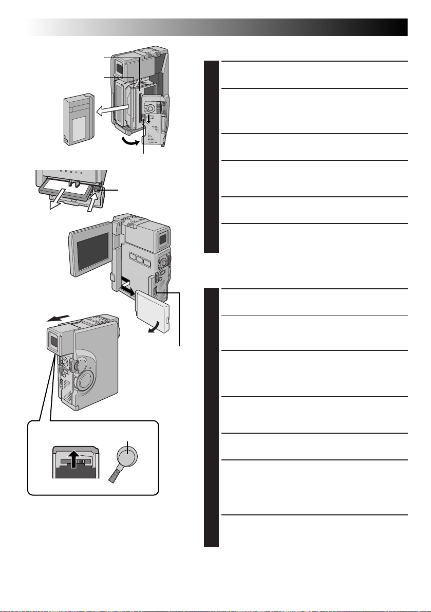
98 EN
Cassette holder
PUSH HERE
Remove.
OPEN/EJECT Switch
EJECT
BATT. RELEASE
Switch
USER MAINTENANCE
After Use
Turn off the camcorder.
1
Slide down OPEN/EJECT in the direction of the
2
arrow, then swing the cover open until it locks. The
cassette holder opens automatically. Remove the
cassette.
Press “PUSH HERE” to close the cassette cover.
3
Open the card cover, then press EJECT. The
4
MultiMediaCard is disengaged from the camcorder.
Remove the MultiMediaCard.
Close the card cover.
5
Slide down BATT. RELEASE and remove the battery
6
pack.
Cleaning The Camcorder
CLEAN EXTERIOR
1
Wipe gently with a soft cloth.
•Put cloth in diluted mild soap and wring it well to
wipe off heavy dirt. Then wipe again with a dry
cloth.
CLEAN LCD MONITOR
2
Wipe gently with the provided cleaning cloth or a
commercially available soft cloth. Be careful not to
damage the monitor. Close the LCD monitor.
Bottom of
viewfinder
Blower brush
1
Gap
2
NOTES:
●
Avoid using strong cleaning agents such as
benzine or alcohol.
●
Cleaning should be done only after the
battery pack has been removed or other
power units have been disconnected.
●
Mold may form if the lens is left dirty.
●
When using a cleaner or chemically treated
cloth refer to the cautions of each product.
CLEAN LENS
3
Blow it with a blower brush, then wipe gently with
lens cleaning paper.
PULL OUT VIEWFINDER FULLY
4
CLEAN VIEWFINDER
5
Slide the cover in the direction of the arrow 1. Insert
a lens blower or a soft cloth into the gap at the
bottom of the viewfinder and clean the interior of the
viewfinder with it 2.
PUSH VIEWFINDER BACK IN
6
Close the cover until it locks in place. Push the
viewfinder back in.
Page 99
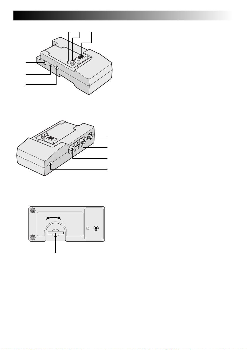
INDEX
1
2
3
Docking Station
4
!
EN99
65
7
8
9
0
1 JLIP (Joint Level Interface Protocol) Connector
Connect to a JLIP-compatible camcorder or VCR
to control it from the computer using the provided
Software.
NOTE:
Make sure that the camcorder is turned on while
connecting the camcorder to a PC using the
Docking Station’s JLIP connector. If the camcorder
is turned off (because the Power Switch is set to
“OFF” or due to Auto Shut Off* etc.) while the
JLIP programmeme software is used, it will be
impossible to control the connected devices from
the computer. In such a case, first try turning the
camcorder on again, or unplug the JLIP connection cable from the Docking Station’s JLIP
connector. Then, initialise or run the software
again.
* Auto Shut Off:
If 5 minutes elapse in the Record-Standby mode
or in the Pause mode, the camcorder’s power
shuts off automatically to conserve energy.
2 PC Connector [DIGITAL STILL] ........... Z pg. 72
3 Edit Connector [EDIT] ......................... Z pg. 85
Connect the editing cable when performing
Random Assemble Editing (Z pg. 84 – 89).
4 Stud .................................................... Z pg. 70
5 Screw ................................................. Z pg. 70
6 Multi Connector
The Docking Station can be connected with this
camcorder through this connector. Never touch it
with your hand or hit it with a hard object; if the
pins are damaged, the connectors will become
unusable due to contact failure.
7 S-Video Output Connector
[S OUT] ....................................... Z pg. 70, 85
8 Video Output Connector
[VIDEO] ....................................... Z pg. 70, 85
9 Audio Output Connector
[AUDIO L/R] ................................ Z pg. 70, 85
0 External Stereo Microphone Input
Connector [MIC]................................. Z pg. 90
! Screw Knob ........................................ Z pg. 70
To attach the camcorder, tighten this clockwise.
Page 100
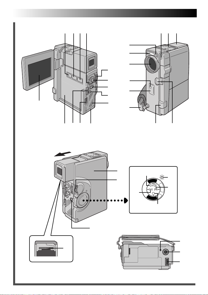
100 EN
INDEX
Controls, Connectors And Indicators
Q
1 2 3 4
E T
9
0
5
6
7
8
W
Y
!
t
r
u
w
p
R
@
$
#
Y
A
L
P
Y
A
L
iy o
) (
e
P
/
C
O
F
F
C
A
M
E
R
^
A
5
S
D
S
C
D
S
C
P
*
%
&
U
I
q
 Loading...