

JVC EX-D11J, EX-D11EE, EX-D11A, EX-D11US, EX-D11UB Service Manual
...
SERVICE MANUAL
COMPACT COMPONENT SYSTEM
MB54420067
EX-D11J,EX-D11EE,EX-D11A,
EX-D11US,EX-D11UB,EX-D11UP,
EX-D11UT,EX-D11UW,EX-D11UY,
EX-D11UG
Lead free solder used in the board (material : Sn-Ag-Cu, melting point : 219 Centigrade)
1 PRECAUTION. . . . . . . . . . . . . . . . . . . . . . . . . . . . . . . . . . . . . . . . . . . . . . . . . . . . . . . . . . . . . . . . . . . . . . . . . 1-3
2 SPECIFIC SERVICE INSTRUCTIONS . . . . . . . . . . . . . . . . . . . . . . . . . . . . . . . . . . . . . . . . . . . . . . . . . . . . . . 1-6
3 DISASSEMBLY . . . . . . . . . . . . . . . . . . . . . . . . . . . . . . . . . . . . . . . . . . . . . . . . . . . . . . . . . . . . . . . . . . . . . . . 1-7
4 ADJUSTMENT . . . . . . . . . . . . . . . . . . . . . . . . . . . . . . . . . . . . . . . . . . . . . . . . . . . . . . . . . . . . . . . . . . . . . . . 1-23
5 TROUBLESHOOTING . . . . . . . . . . . . . . . . . . . . . . . . . . . . . . . . . . . . . . . . . . . . . . . . . . . . . . . . . . . . . . . . . 1-27
COPYRIGHT © 2006 Victor Company of Japan, Limited
CA-EXD11
TABLE OF CONTENTS
SP-EXD11SP-EXD11
No.MB544
2006/7
SPECIFICATION
General Power source AC 120 V , 60 Hz (for U.S.A. model)
Power consumption 25 W (in operation)/
Weight: 2.6 kg (5.7 lbs)
External dimensions (W
DVD player Playable discs DVD VIDEO, DVD AUDIO, VCD, SVCD, CD, CD-R/RW (VCD/SVCD/CD/MP3/WMA/JPEG/
Video output Color system NTSC (for U.S.A. model)
Horizontal resolution 500 lines
Composite
S-video
Component × 1 Y output: 1.0 V (p-p)/75 Ω
Audio output Analog sound output Speakers × 2
Output power 20 W per channel min., RMS, at 4
Fitting impedance 4
Headphones × 1 11 mW/32 Ω
Fitting impedance 16 Ω to 1 kΩ
Subwoofer × 1 500 mVrms/10 kΩ
Digital sound output Optical × 1 -21 dBm to -15 dBm
Audio input Sound input AUX 1 400 mV/50 k
Tuner FM tuner Receiving frequency 87.5 MHz to 108.0 MHz
AM (MW) tuner Receiving frequency 531 kHz to 1 710 kHz (9 kHz) (For Singapore/Hong Kong/South and Central America/Australia)
Speaker Type Full range, 1-way bass-reflex type, Magnetically shielded type
Speaker 8cm (3 3/16 inches) wood cone
Frequency response 55 Hz to 20 000 Hz
Power handling capacity 20 W
Impedance 4
Sound pressure level 80 dB/W m
Dimension (W
Weight 1.8 kg (4.0 lbs) each
• Manufactured under license from Dolby Laboratories. "Dolby", "Pro Logic", "MLP lossless", and the double-D symbol are trademarks of Dolby
Laboratories.
• "DTS" and "DTS 2.0+ Digital Out" are trademarks of Digital Theater Systems, Inc.
• "Official DivX® Certified product", "Plays all versions of DivX® video (including DivX® 6) with standard playback of DivX® media files", "DivX,
DivX certified, and associated logos are trademarks of DivX, Inc. and are used under licence.
• USE OF THIS PRODUCT IN ANY MANNER THAT COMPLIES WITH THE MPEG-4 VISUAL STANDARD IS PROHIBITED, EXCEPT FOR USE
BY A CONSUMER ENGAGING IN PERSONAL AND NON-COMMERCIAL ACTIVITIES.
• This product incorporates copyright protection technology that is protected by U.S. patents and other intellectual property rights. Use of this copyright protection technology must be authorized by Macrovision, and is intended for home and other limited viewing uses only unless otherwise
authorized by Macrovision. Reverse engineering or disassembly is prohibited.
× 1 1.0 V (p-p)/75 Ω, synchronization negative
× 1 Y output: 1.0 V (p-p)/75 Ω, synchronization negative
× H × D) 120 mm × 150.5 mm × 243 mm (43/4 in. × 6 in. × 95/8 in.)
× H × D) 150 mm × 152.6 mm × 252.9 mm (5 15/16 in. × 6 1/16 in. × 10 in.)
AUX 2 1.5 V/50 kΩ
USB AUDIO × 1
Antenna 75
Antenna External antenna jack (loop antenna)
AC 110-240 V , 50/60 Hz (for Asian model)
AC 240 V, 50 Hz (for Australian model)
AC 220 V, 50/60 Hz (for Hong Kong model)
4.0 W (on standby/display on)
1.0 W (on standby/display off)
MPEG1/MPEG2 format)
DVD-R/-RW (MP3/WMA/JPEG/DVD VIDEO/DVD VR [CPRM]/MPEG1/ MPEG2 format)
DVD-ROM (MP3/WMA/JPEG/MPEG1/ MPEG2/DVD VR [CPRM] format)
PAL/NTSC (for Asian model)
For PAL 0.3 V (p-p)/75
For NTSC 0.286 V (p-p)/75 Ω
PB/PR output: 0.7 V (p-p)/75 Ω
Ω
Ω at 1 kHz with no more than 10% total harmonic distortion
Ω to 16 Ω
Ω
200 mV/50 kΩ
750 mV/50 kΩ
Ω Unbalanced type
530 kHz to 1 710 kHz (10 kHz) (For Singapore/Hong Kong/South and Central America/Australia)
531 kHz to 1 602 kHz (9 kHz) (For Middle East and South Africa)
530 kHz to 1 600 kHz (10 kHz) (For Middle East and South Africa)
522 kHz to 1 629 kHz (For Russia)
× 1
Ω
• Designs and Specifications are subject to change without notice.
1-2 (No.MB544)
SECTION 1
PRECAUTION
1.1 Safety Precautions
(1) This design of this product contains special hardware and
many circuits and components specially for safety purposes. For continued protection, no changes should be made
to the original design unless authorized in writing by the
manufacturer. Replacement parts must be identical to
those used in the original circuits. Services should be performed by qualified personnel only.
(2) Alterations of the design or circuitry of the product should
not be made. Any design alterations of the product should
not be made. Any design alterations or additions will void
the manufacturers warranty and will further relieve the
manufacture of responsibility for personal injury or property
damage resulting therefrom.
(3) Many electrical and mechanical parts in the products have
special safety-related characteristics. These characteristics are often not evident from visual inspection nor can the
protection afforded by them necessarily be obtained by using replacement components rated for higher voltage, wattage, etc. Replacement parts which have these special
safety characteristics are identified in the Parts List of Service Manual. Electrical components having such features
are identified by shading on the schematics and by ( ) on
the Parts List in the Service Manual. The use of a substitute
replacement which does not have the same safety characteristics as the recommended replacement parts shown in
the Parts List of Service Manual may create shock, fire, or
other hazards.
(4) The leads in the products are routed and dressed with ties,
clamps, tubings, barriers and the like to be separated from
live parts, high temperature parts, moving parts and/or
sharp edges for the prevention of electric shock and fire
hazard. When service is required, the original lead routing
and dress should be observed, and it should be confirmed
that they have been returned to normal, after reassembling.
(5) Leakage shock hazard testing
After reassembling the product, always perform an isolation check on the exposed metal parts of the product (antenna terminals, knobs, metal cabinet, screw heads,
headphone jack, control shafts, etc.) to be sure the product
is safe to operate without danger of electrical shock.Do not
use a line isolation transformer during this check.
• Plug the AC line cord directly into the AC outlet. Using a
"Leakage Current Tester", measure the leakage current
from each exposed metal parts of the cabinet, particularly any exposed metal part having a return path to the
chassis, to a known good earth ground. Any leakage current must not exceed 0.5mA AC (r.m.s.).
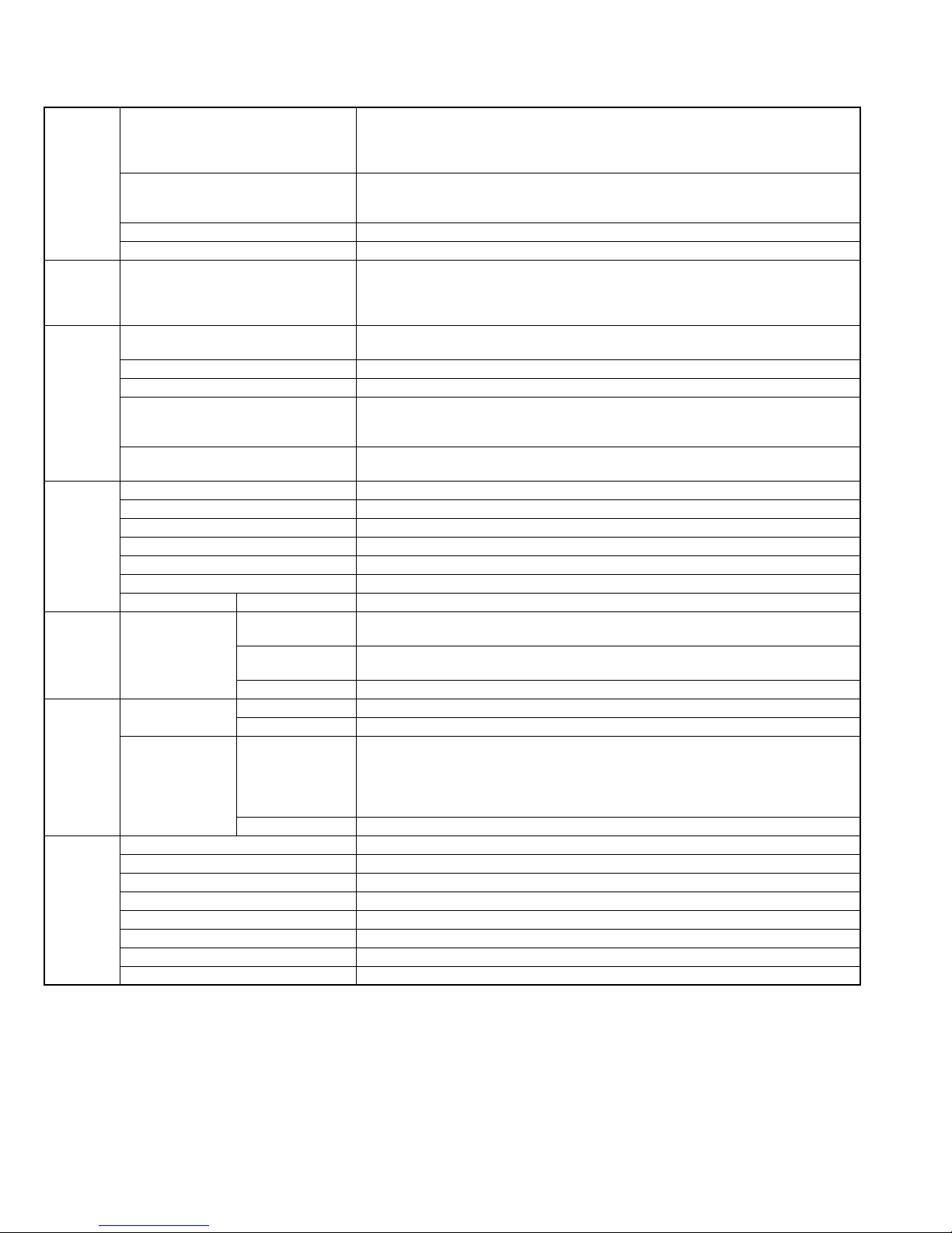
• Alternate check method
Plug the AC line cord directly into the AC outlet. Use an
AC voltmeter having, 1,000Ω per volt or more sensitivity
in the following manner. Connect a 1,500Ω 10W resistor
paralleled by a 0.15µF AC-type capacitor between an ex-
posed metal part and a known good earth ground.
Measure the AC voltage across the resistor with the AC
voltmeter.
Move the resistor connection to each exposed metal
part, particularly any exposed metal part having a return
path to the chassis, and measure the AC voltage across
the resistor. Now, reverse the plug in the AC outlet and
repeat each measurement. Voltage measured any must
not exceed 0.75 V AC (r.m.s.). This corresponds to 0.5
mA AC (r.m.s.).
AC VOLTMETER
(Having 1000
ohms/volts,
or more sensitivity)
0.15 F AC TYPE
Place this
probe on
1500 10W
Good earth ground
1.2 Warning
(1) This equipment has been designed and manufactured to
meet international safety standards.
(2) It is the legal responsibility of the repairer to ensure that
these safety standards are maintained.
(3) Repairs must be made in accordance with the relevant
safety standards.
(4) It is essential that safety critical components are replaced
by approved parts.
(5) If mains voltage selector is provided, check setting for local
voltage.
1.3 Caution
Burrs formed during molding may be left over on some parts
of the chassis.
Therefore, pay attention to such burrs in the case of preforming repair of this system.
1.4 Critical parts for safety
In regard with component parts appearing on the silk-screen
printed side (parts side) of the PWB diagrams, the parts that are
printed over with black such as the resistor ( ), diode ( )
and ICP ( ) or identified by the " " mark nearby are critical
for safety. When replacing them, be sure to use the parts of the
same type and rating as specified by the manufacturer.
(This regulation dose not Except the J and C version)
each exposed
metal part.
(No.MB544)1-3
1.5 Preventing static electricity
Electrostatic discharge (ESD), which occurs when static electricity stored in the body, fabric, etc. is discharged, can destroy the laser
diode in the traverse unit (optical pickup). Take care to prevent this when performing repairs.
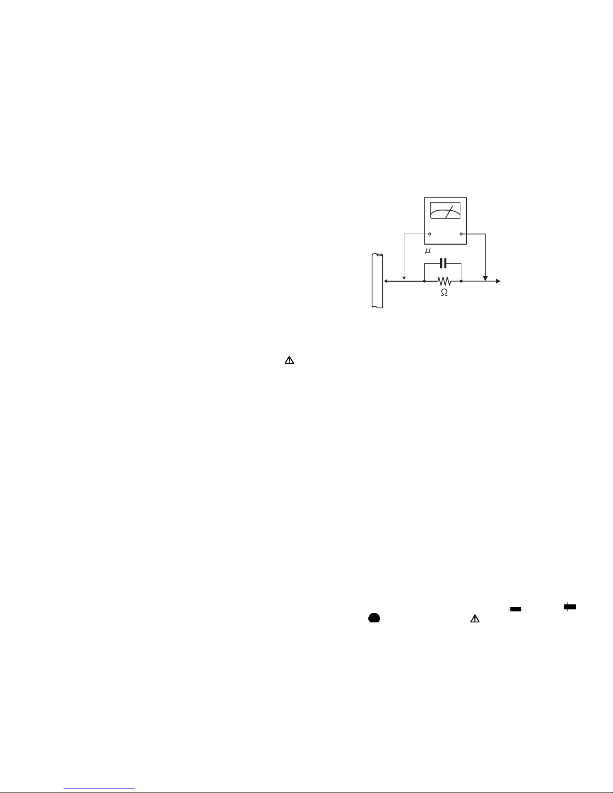
1.5.1 Grounding to prevent damage by static electricity
Static electricity in the work area can destroy the optical pickup (laser diode) in devices such as laser products.
Be careful to use proper grounding in the area where repairs are being performed.
(1) Ground the workbench
Ground the workbench by laying conductive material (such as a conductive sheet) or an iron plate over it before placing the
traverse unit (optical pickup) on it.
(2) Ground yourself
Use an anti-static wrist strap to release any static electricity built up in your body.
(caption)
Anti-static wrist strap
1M
Conductive material
(conductive sheet) or iron palate
(3) Handling the optical pickup
• In order to maintain quality during transport and before installation, both sides of the laser diode on the replacement optical
pickup are shorted. After replacement, return the shorted parts to their original condition.
(Refer to the text.)
• Do not use a tester to check the condition of the laser diode in the optical pickup. The tester's internal power source can easily
destroy the laser diode.
1.6 Handling the traverse unit (optical pickup)
(1) Do not subject the traverse unit (optical pickup) to strong shocks, as it is a sensitive, complex unit.
(2) Cut off the shorted part of the flexible cable using nippers, etc. after replacing the optical pickup. For specific details, refer to the
replacement procedure in the text. Remove the anti-static pin when replacing the traverse unit. Be careful not to take too long a
time when attaching it to the connector.
(3) Handle the flexible cable carefully as it may break when subjected to strong force.
(4) I t is not possible to adjust the semi-fixed resistor that adjusts the laser power. Do not turn it.
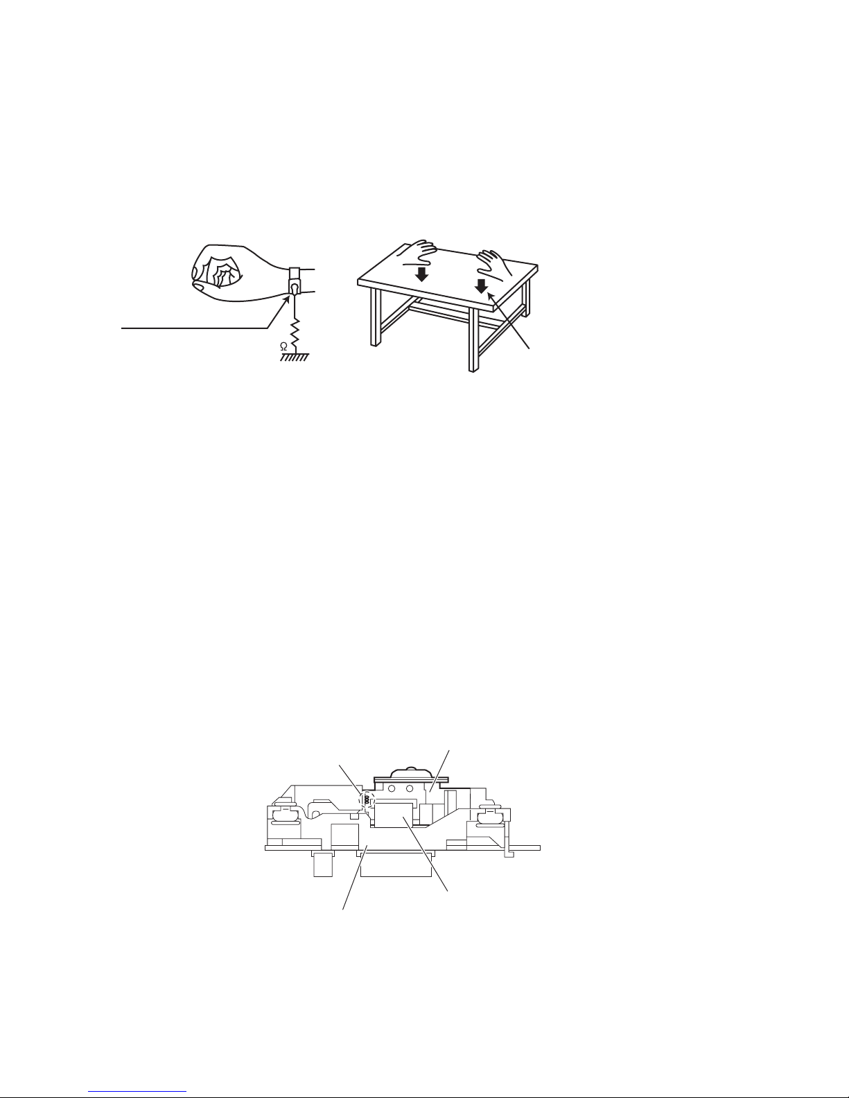
1.7 Attention when traverse unit is decomposed
*Please refer to "Disassembly method" in the text for the pickup unit.
• Apply solder to the short land sections before the card wire is disconnected from the connecto on the servo board. (If the card wire
is disconnected without applying solder, the pickup may be destroyed by static electricity.)
• In the assembly, be sure to remove solder from the short land sections after connecting the card wire.
DVD pickup
short land sections
Traverse mechanism assembly
1-4 (No.MB544)
Card wire
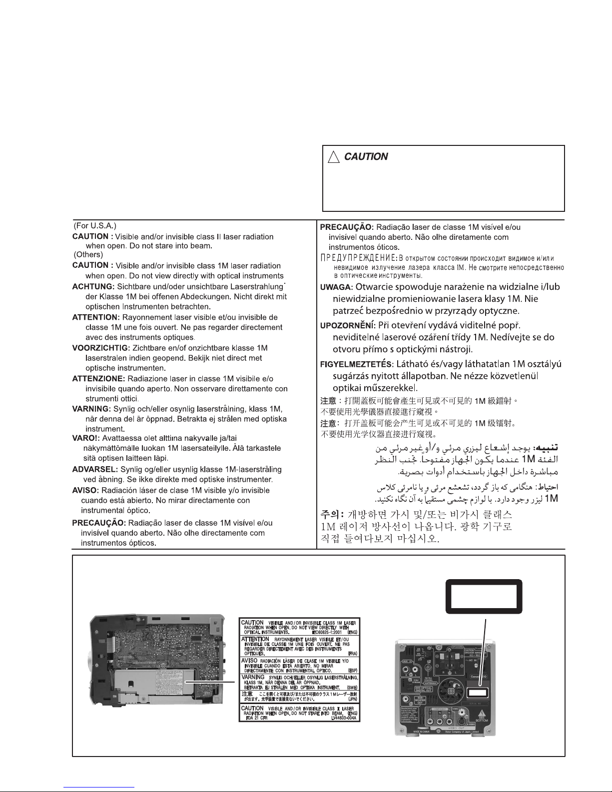
1.8 Important for laser products
1.CLASS 1 LASER PRODUCT
2.CAUTION :
(For U.S.A.) Visible and/or invisible class II laser radiation
when open. Do not stare into beam.
(Others) Visible and/or invisible class 1M laser radiation
when open. Do not view directly with optical instruments.
3.CAUTION : Visible and/or invisible laser radiation when
open and inter lock failed or defeated. Avoid direct
exposure to beam.
4.CAUTION : This laser product uses visible and/or invisible
laser radiation and is equipped with safety switches which
prevent emission of radiation when the drawer is open and
the safety interlocks have failed or are defeated. It is
dangerous to defeat the safety switches.
5.CAUTION : If safety switches malfunction, the laser is able
to function.
6.CAUTION : Use of controls, adjustments or performance of
procedures other than those specified here in may result in
hazardous radiation exposure.
!
Please use enough caution not to
see the beam directly or touch it
in case of an adjustment or operation
check.
REPRODUCTION AND POSITION OF LABELS and PRINT
WARNING LABEL and PRINT
CLASS 1
LASER PRODUCT
CLASS 1
LASER PRODUCT
(No.MB544)1-5

SECTION 2
SPECIFIC SERVICE INSTRUCTIONS
This service manual does not describe SPECIFIC SERVICE INSTRUCTIONS.
1-6 (No.MB544)
SECTION 3
A
DISASSEMBLY
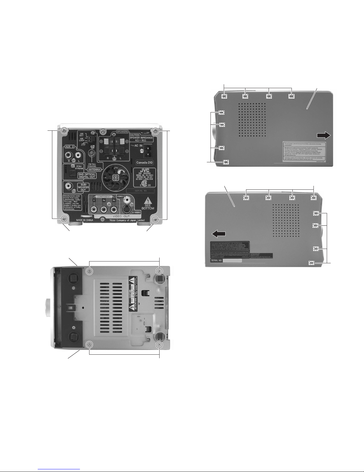
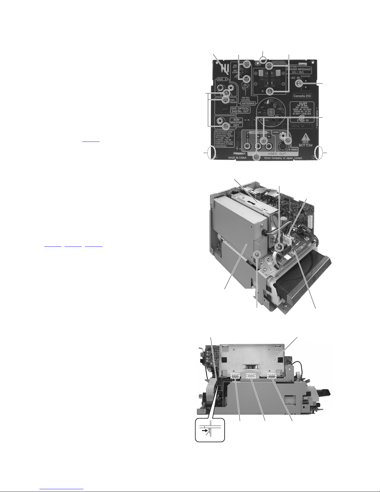
3.1 Main body section
3.1.1 Removing the side panel L and side panel R
(See Figs.1 to 4)
(1) From the back side of the main body, remove the four
screws A attaching the side panels L/R. (See Fig.1.)
(2) From the bottom side of the main body, remove the four
screws B attaching the side panels L/R. (See Fig.2.)
(3) From the both sides of the main body, release the joint a in
the direction of the arrow and remove the side panels L/R
toward this side. (See Figs.3 and 4.)
A
a
a
Side panel L
Side panel R
Fig.3
a
Side panel R Side panel L
Fig.1
Side panel R
Side panel L
Fig.2
B
a
Fig.4
B
(No.MB544)1-7
3.1.2 Removing the top panel assembly
(See Figs.5 and 6)
• Remove the side panels L/R.
(1) From the both sides of the main body, remove the two
screws C. (See Figs.5 and 6)
(2) From the back side of the main body, remove the screw D
attaching the top panel assembly. (See Fig.6.)
(3) From the both sides of the main body, release the joints b
and c. (See Figs.5 and 6.)
(4) Take out the top panel assembly in the direction of the ar-
row. (See Fig.6.)
C
c
Fig.5
Top panel assembly
b c
D
Top panel assembly
b
C
1-8 (No.MB544)
Fig.6
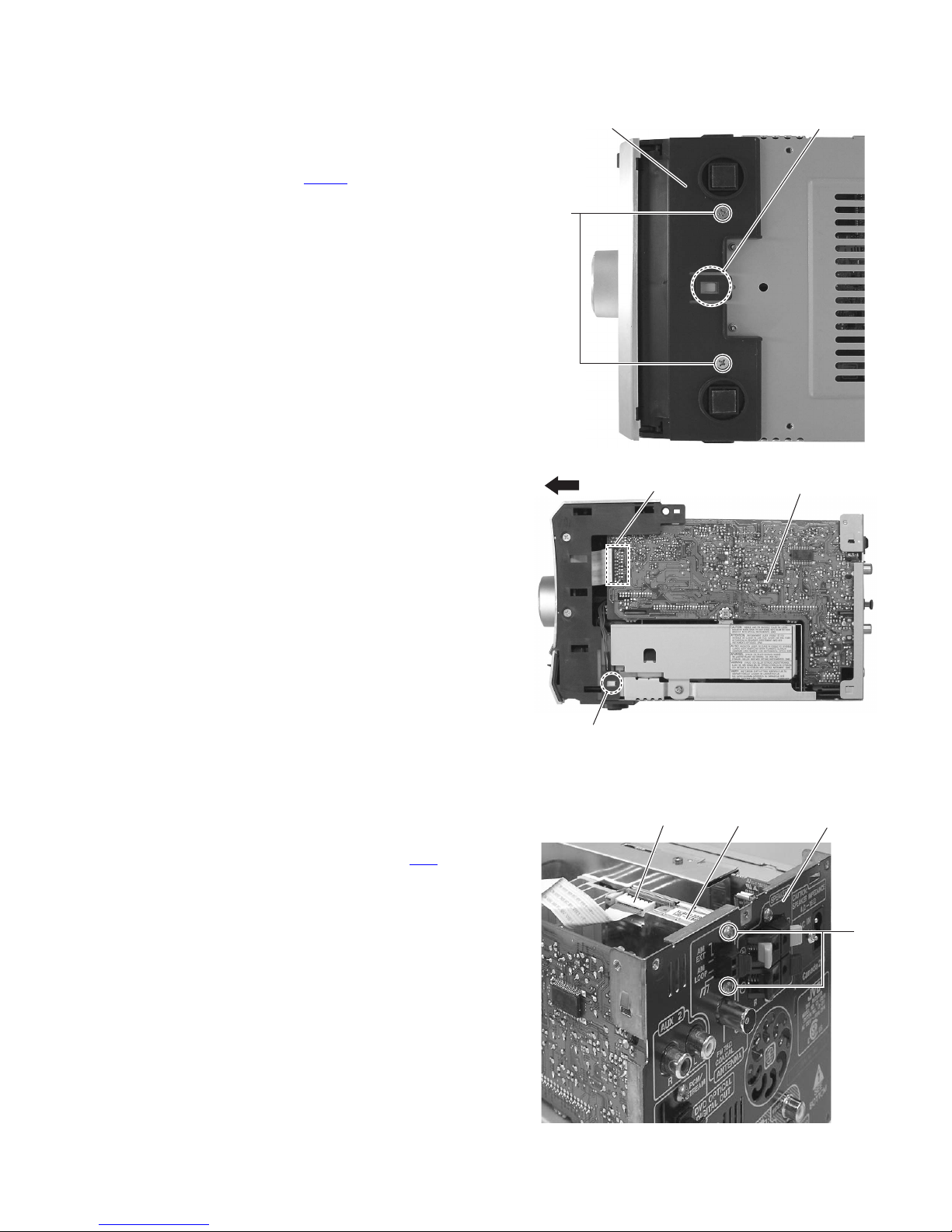
3.1.3 Removing the front panel assembly
(See Figs.7 and 8)
• Remove the side panels L/R and top panel assembly.
(1) From the bottom side of the main body, remove the two
screws E attaching the front panel assembly. (See Fig.7.)
(2) From the forward side of the micom board, disconnect the
card wire from the connector CN426
(3) From the bottom and both sides of the main body, release
the joints (d, e) of the front panel assembly and remove the
front panel assembly in the direction of the arrow. (See
Figs.7 and 8.)
. (See Fig.8.)
Front panel assembly
E
CN426
d
Fig.7
Micom board
3.1.4 Removing the tuner
(See Fig.9)
• Remove the side panels L/R and top panel assembly.
(1) From the back side of the main body, remove the two
screws F attaching the tuner to the rear panel.
(2) Disconnect the card wire from the connector CN1
tuner.
on the
e
Fig.8
Tuner Rear panelCN1
F
Fig.9
(No.MB544)1-9
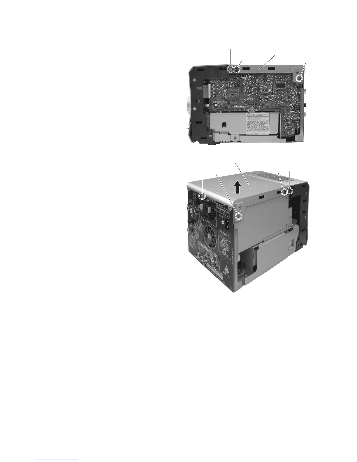
3.1.5 Removing the rear panel
(See Fig.10)
• Remove the side panels L/R and top panel assembly.
(1) From the back side of the main body, remove the ten
screws G and screw H attaching the rear panel.
(2) From the top side of the main body, disconnect the earth
wire from the rear panel.
(3) From the both sides of the main body, release the joints f
and remove the rear panel.
3.1.6 Removing the switching power supply
(See Figs.10 and 11)
• Remove the side panels L/R and top panel assembly.
(1) From the back side of the main body, remove the screw H
attaching the rear panel. (See Fig.10.)
(2) From the top side of the main body, disconnect the wire
from the connector CN200
Fig.11.)
(3) From the left side of the main body, remove the screw J at-
taching the main body. (See Fig.11.)
(4) Take out the switching power supply. (See Fig.11.)
3.1.7 Removing the digital amplifier board assembly
(See Figs.11 and 12)
• Remove the side panels L/R, top panel assembly, rear panel
and switching power supply.
(1) From the top side of the main body, remove the screw K at-
taching the digital amplifier board assembly. (See Fig.11.)
Reference:
When attaching the screw K, attach the earth wire with it.
(2) From the left side of the main body, disconnect the connec-
tors (CN310
assembly from the regulator board. (See Fig.12.)
(3) Release the joint g of the shield case B in the direction of
the arrow and take out the digital amplifier board assembly
from the regulator board. (See Fig.12.)
, CN311, CN312) on the digital amplifier board
on the regulator board. (See
Earth wire
Rear panel
GG
G
f
Fig.10
Digital amplifier board assembly
H
G
f
K
CN200
Switching power supply
Regulator board
CN312 CN311 CN310
g
J
Fig.11
Digital amplifier board assembly
Fig.12
Regulator board
1-10 (No.MB544)
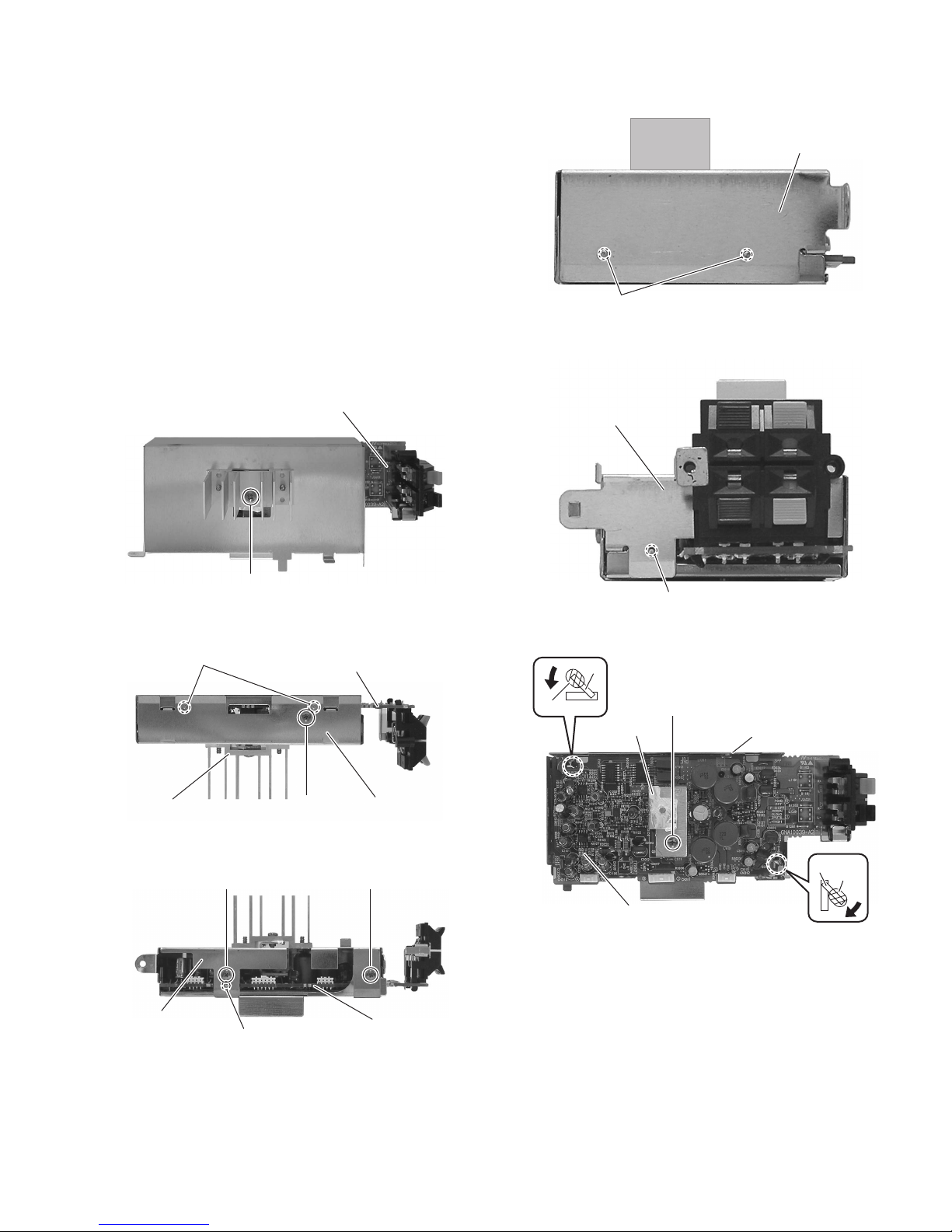
3.1.8 Removing the digital amplifier board
(See Figs.13 to 18)
• Remove the side panels L/R, top panel assembly, rear panel,
switching power supply and digital amplifier board assembly.
(1) From the forward side of the digital amplifier board assem-
bly, remove the screw M. (See Fig.13.)
(2) From the top and bottom sides of the digital amplifier board
assembly, remove the three screws N. (See Figs.14 and
15.)
(3) Release the joints (h, j, k, m) and remove the shield case
B with the heat sink in the direction of the arrow. (See
Figs.14 to 17.)
(4) From the forward side of the digital amplifier board, remove
the screw N attaching the heat sink. (See Fig.18.)
(5) Remove the solders from the soldered sections (n, p) and
bend the sections (q, r) of the shield case A in the direction
of the arrow. (See Fig.18.)
(6) Take out the digital amplifier board from the shield case A.
Shield case B
k
Fig.16
Heat sink
Digital amplifier board
M
Fig.13
h
N
Digital amplifier board
Shield case B
N
Fig.14
N
Shield case B
q
n
Heat sink
m
N
Fig.17
Shield case A
r
p
Shield case B
j
Digital amplifier board
Fig.15
Digital amplifier board
Fig.18
(No.MB544)1-11
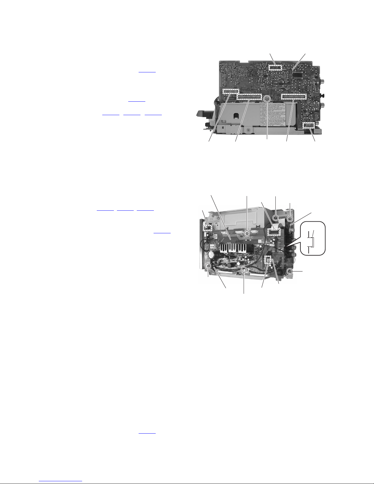
3.1.9 Removing the micom board
(See Fig.19)
• Remove the side panels L/R, top panel assembly, rear panel
and front panel assembly.
(1) From the right side of the main body, remove the screw P
attaching the micom board.
(2) Disconnect the card wire from the connector CN421
forward side of the micom board.
Reference:
Remove the tuner as required. (See Fig.9)
(3) Disconnect the wire from the connector CN501
ward side of the micom board.
(4) Disconnect the connectors (CN423
the micom board from the regulator and video boards toward this side to remove the micom board.
, CN424, CN425) on
on the
on the for-
CN421
Micom board
3.1.10 Removing the regulator board
(See Fig.20)
• Remove the side panels L/R, top panel assembly, tuner, rear
panel, switching power supply, digital amplifier board assembly and micom board.
(1) From the top side of the main body, disconnect the card
wires from the connectors (CN208
regulator board.
Reference:
When connecting the card wire to the connector CN208
pass it through the hole s of the regulator board as before.
(2) Remove the screws Q and Q'.
Reference:
When attaching the screw Q', attach the earth wire with
it.
(3) Remove the screws Q".
Reference:
When attaching the screw Q", attach the earth wire and
the wire holder with it.
(4) Remove the screw R and screw S' attaching the earth wire.
Reference:
When attaching the screw R and S', attach the earth wire
with it.
, CN210, CN212) on the
CN501
Regulator board
CN210
,
CN424 CN423 CN425
Q
P
Fig.19
CN212
R
S'
Video board
CN703
S
Q''
Wire holder
CN208
s
Q'
Fig.20
3.1.11 Removing the video board
(See Fig.20)
• Remove the side panels L/R, top panel assembly, tuner, rear
panel, switching power supply, digital amplifier board assembly and micom board.
Reference:
Remove the regulator board as required.
(1) From the top side of the main body, remove the two screws
S.
Reference:
When attaching the screw S, attach the earth wire with it.
(2) Take out the video board from the main body.
(3) Disconnect the card wire from the connector CN703
video board.
1-12 (No.MB544)
on the
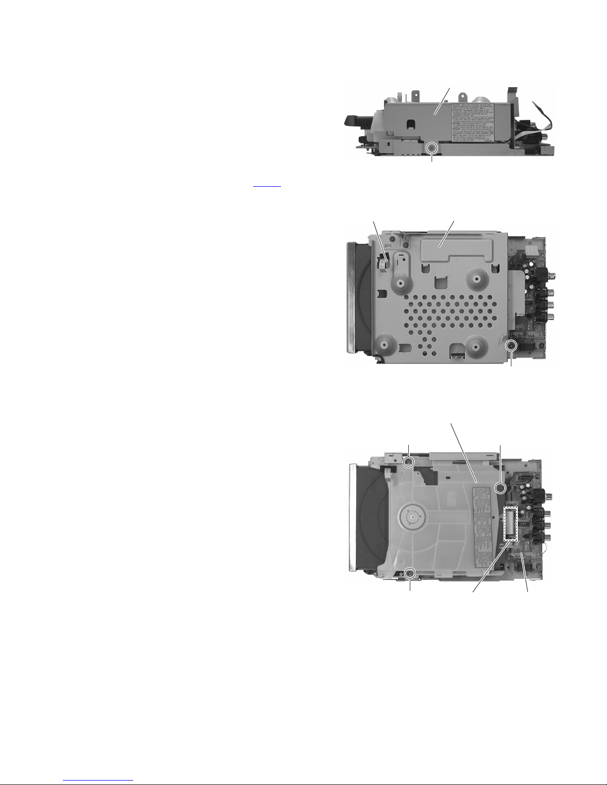
3.1.12 Removing the DVD mechanism assembly
(See Figs.21 to 23)
• Remove the side panels L/R, top panel assembly, front panel
assembly, tuner, rear panel, switching power supply, digital
amplifier board assembly, micom board and regulator board.
(1) From the right side of the main body, remove the screw T
attaching the metal chassis. (See Fig.21.)
(2) From the top side of the main body, remove the screw U
and take out the metal chassis. (See Fig.22.)
Reference:
When attaching the metal chassis, pass the card wire
through the hole t on the metal chassis as before.
(3) Disconnect the card wire from the connector CN703
video board. (See Fig.23.)
(4) Remove the three screws V and take out the DVD mecha-
nism assembly from the bottom chassis. (See Fig.23.)
on the
Metal chassis
T
Fig.21
t
Metal chassis
Fig.22
DVD mechanism assembly
V
V
CN703
Fig.23
V
U
Video board
(No.MB544)1-13
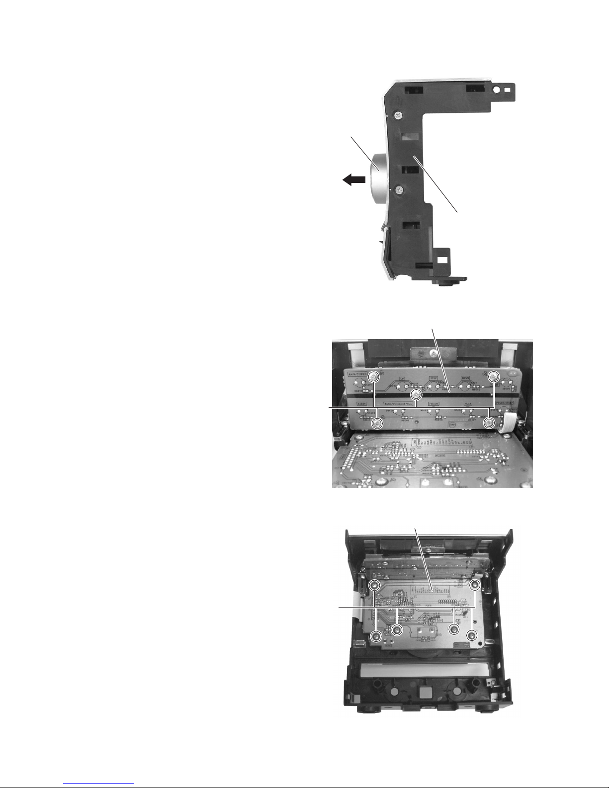
3.1.13 Removing the switch board and front FL board
(See Figs.24 to 26)
• Remove the side panels L/R, top panel and front panel assem-
bly.
(1) From the front side of the main body, pull out the volume
knob assembly in the direction of the arrow. (See Fig.24.)
(2) From the inside of the front panel assembly, remove the
five screws W attaching the switch board. (See Fig.25.)
(3) Remove the six screws X attaching the front FL board.
(See Fig.26.)
(4) Take out the switch board and the front FL board.
Volume knob
assembly
Front panel
assembly
Fig.24
Switch board
W
Fig.25
Front FL board
X
1-14 (No.MB544)
Fig.26
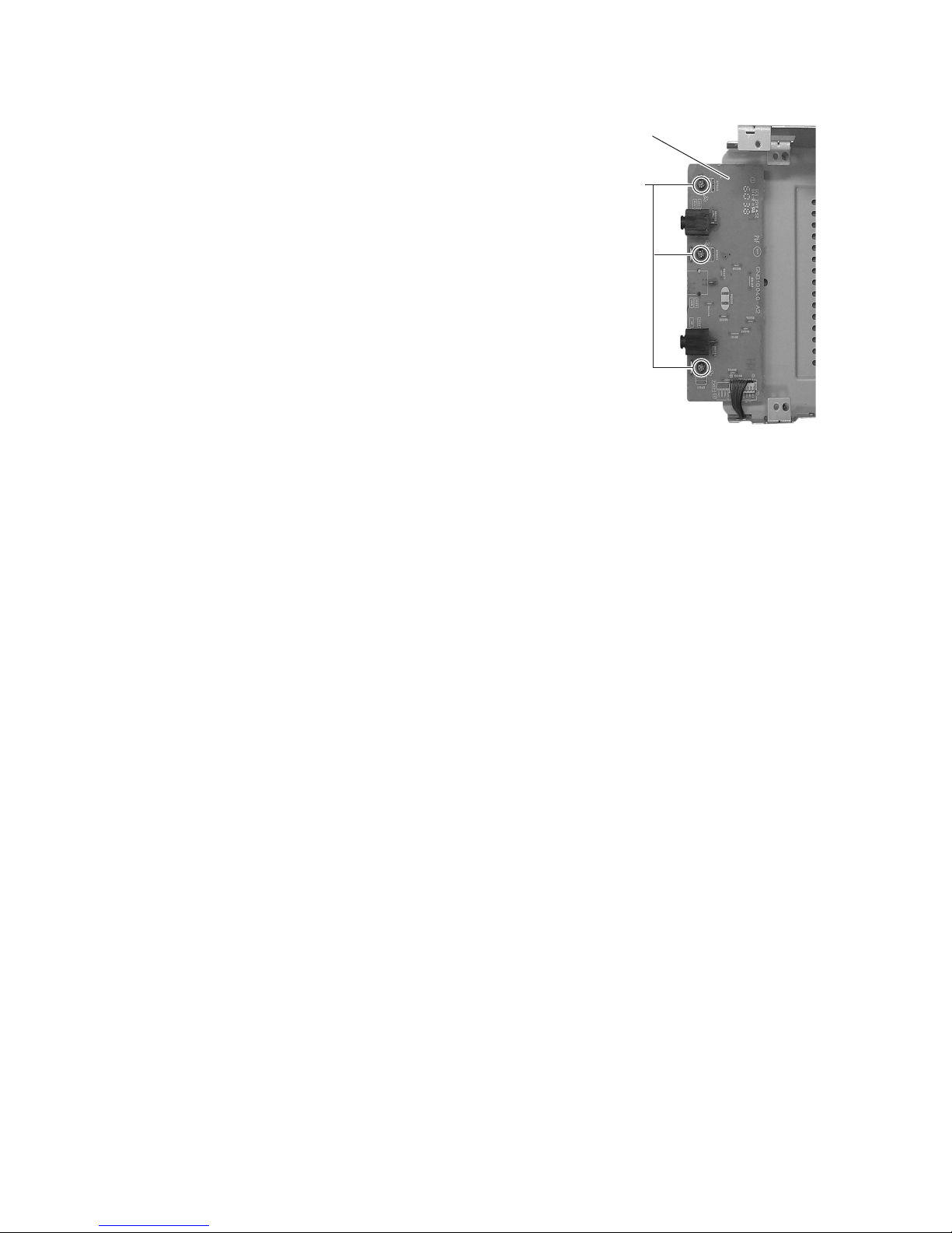
3.1.14 Removing the headphone board
(See Fig.27)
• Remove the side panels L/R, top panel assembly, front panel
assembly, tuner, rear panel, switching power supply, digital
amplifier board assembly, micom board, regulator board and
DVD mechanism assembly.
(1) Remove the three screws Y and take out the headphone
board.
(2) Take out the headphone board.
Headphone board
Y
Fig.27
(No.MB544)1-15
3.2 DVD mechanism assembly section
• Remove the DVD mechanism assembly from the main body.
(See "Removing the DVD mechanism assembly" of the DVD player section.)
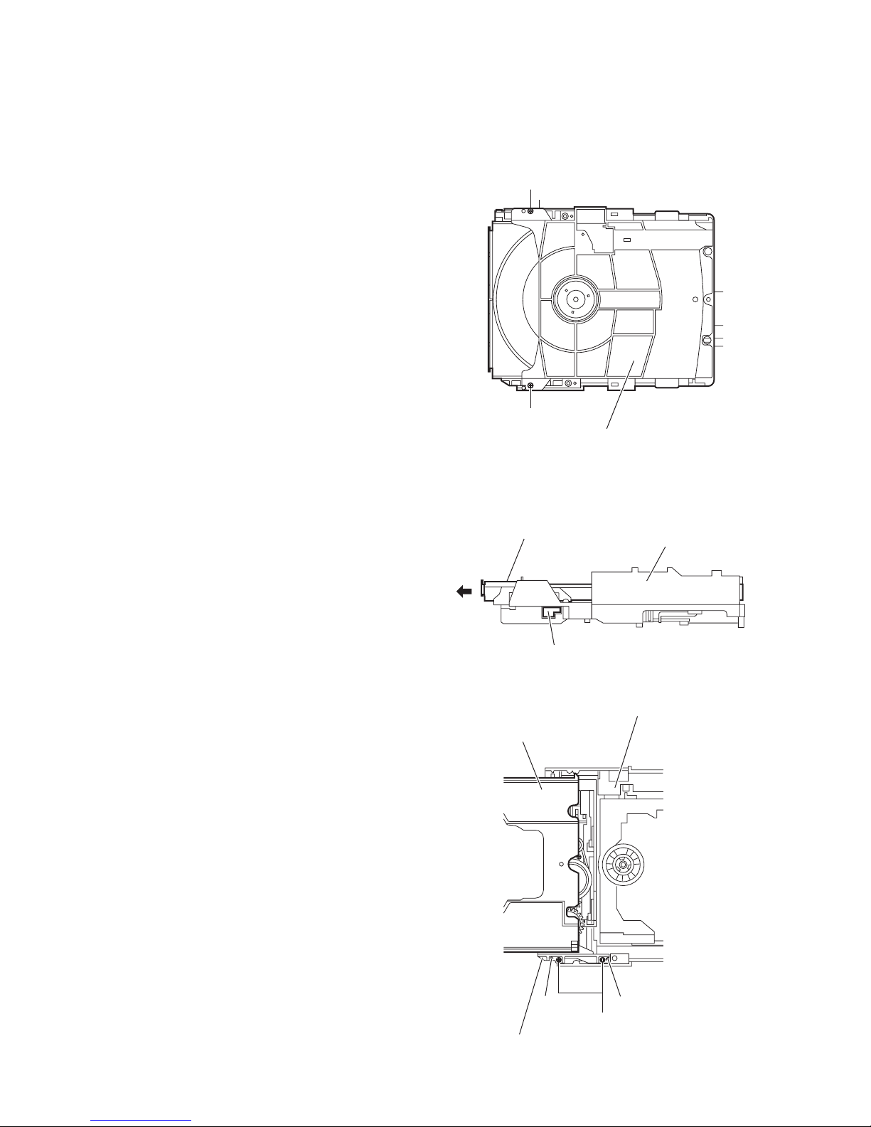
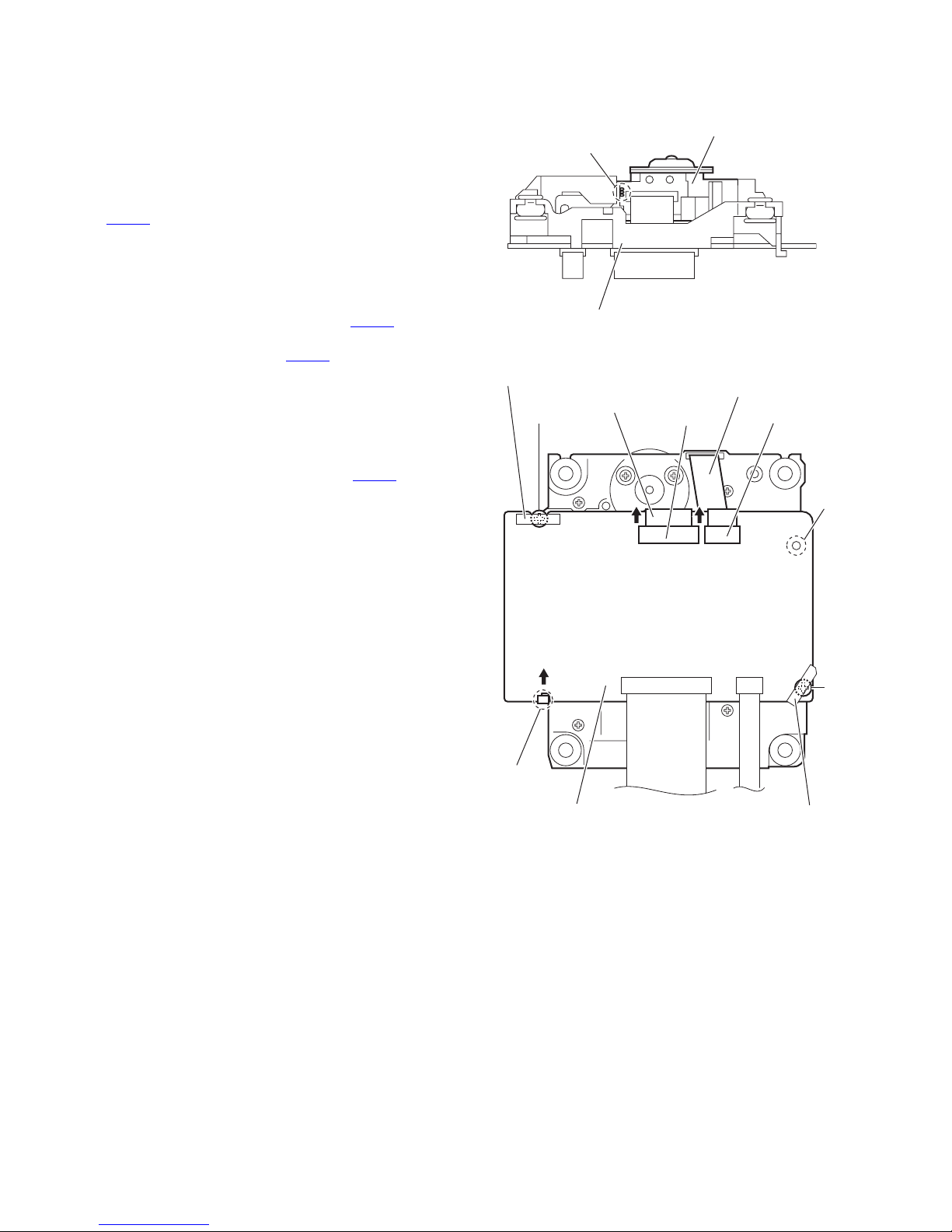
3.2.1 Removing the clamper base
(See Fig.1)
(1) From the top side of the DVD mechanism assembly, re-
move the two screws A attaching the clamper base.
(2) Take out the clamper base.
A
3.2.2 Removing the tray assembly
(See Figs.2 and 3)
• Remove the clamper base.
(1) From the right side of the DVD mechanism assembly, push
the slide cam and pull the tray assembly out of the DVD
mechanism assembly in the direction of the arrow. (See
Fig.2.)
(2) From the top side of the DVD mechanism assembly, re-
move the two screws B attaching the tray assembly. (See
Fig.3.)
(3) Remove the shaft guide of the tray assembly from the pro-
jections a of the DVD mechanism assembly and take out
the tray assembly. (See Fig.3.)
A
Tray assembly
Slide cam
DVD mechanism assembly
Tray assembly
Clamper base
Fig.1
DVD mechanism assembly
Fig.2
1-16 (No.MB544)
a
Shaft guide
a
B
Fig.3
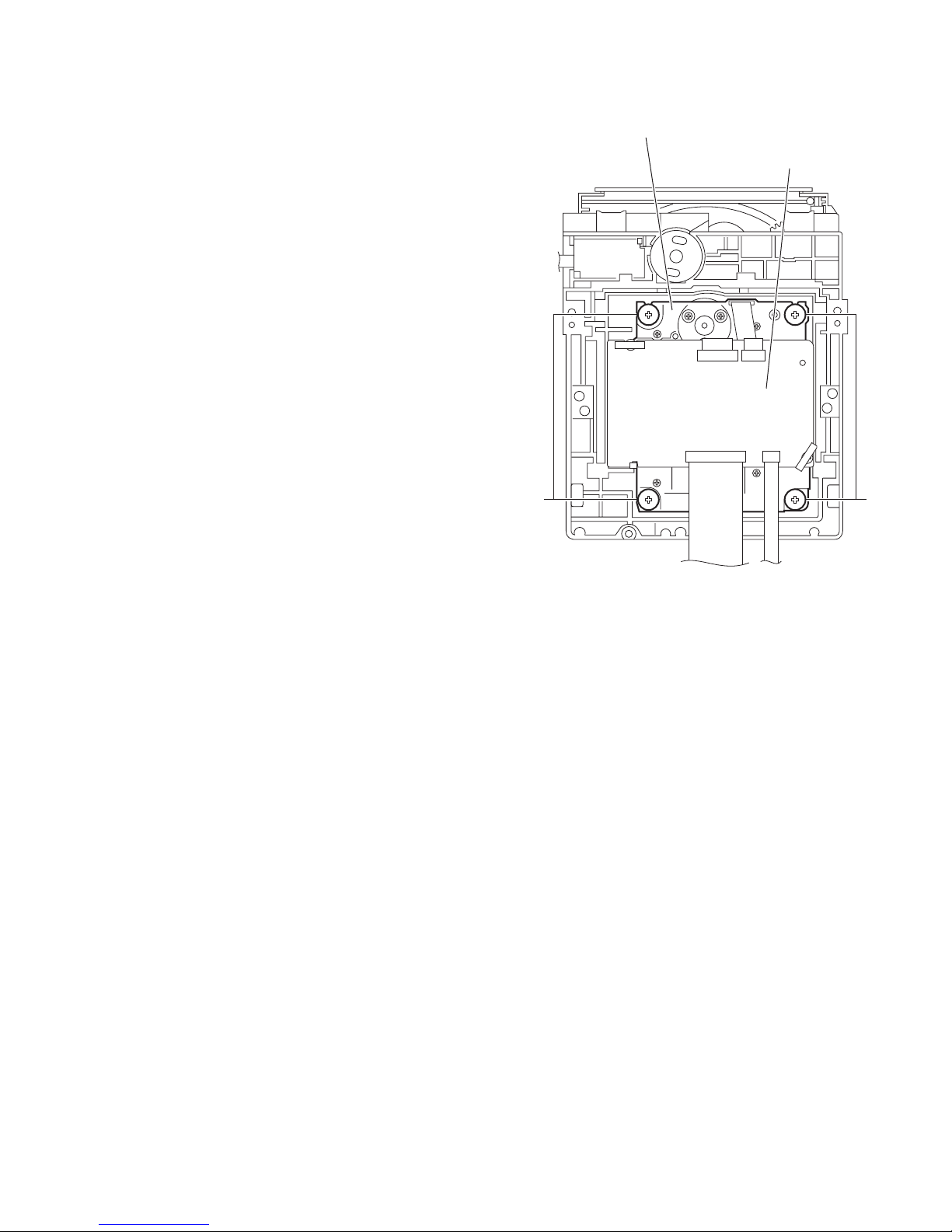
3.2.3 Removing the traverse mechanism assembly
(See Fig.4)
• Remove the clamper base.
(1) From the bottom side of the DVD mechanism assembly, re-
move the four screws C attaching the traverse mechanism
assembly.
(2) Take out the traverse mechanism assembly with the DVD
module board.
Traverse mechanism assembly
DVD module board
CC
Fig.4
(No.MB544)1-17
3.2.4 Removing the DVD module board
(See Figs.5 and 6)
• Remove the clamper base and traverse mechanism assembly.
(1) Solder the short land sections b on the DVD pickup. (See
Fig.5.)
Caution:
• Solder the short land sections b on the DVD pickup before disconnecting the card wire from the connector
on the DVD module board. If the card wire is
CN101
disconnected without attaching solders, the DVD pickup may be destroyed by static electricity. (See Figs.5
and 6.)
• When attaching the DVD module board, be sure to remove solders from the short land sections b after connecting the card wire to the connector CN101
DVD module board. (See Figs.5 and 6.)
(2) Release the lock of the connector CN101
ule board in the direction of the arrow and disconnect the
card wire. (See Fig.6.)
(3) Remove the spacers on the DVD module board. (See
Fig.6.)
(4) Remove the two screws D attaching the DVD module
board. (See Fig.6.)
(5) Disconnect the card wire from the connector CN201
DVD module board. (See Fig.6.)
(6) Remove the DVD module board from the engagement sec-
tion c in an upward direction and remove it from the hook d
in the direction of the arrow. (See Fig.6.)
on the DVD mod-
on the
on the
b
Traverse mechanism assembly
Spacer
Card wire
D
Fig.5
CN101
DVD pickup
Card wire
CN201
c
d
DVD module board
D
Spacer
Fig.6
1-18 (No.MB544)
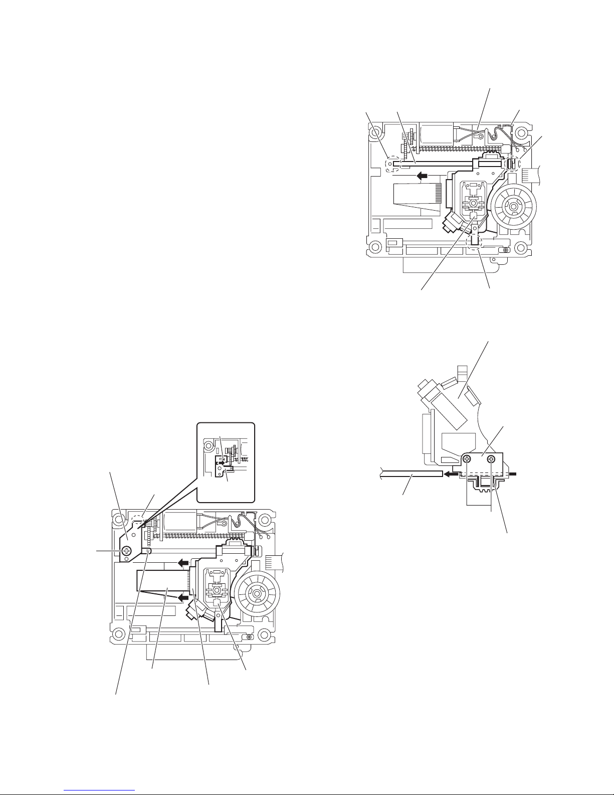
3.2.5 Removing the DVD pickup
(See Figs.5, 7 to 9)
• Remove the clamper base and traverse mechanism assembly.
(1) Solder the short land sections b on the DVD pickup. (See
Fig.5.)
Caution:
• Solder the short land sections b on the DVD pickup before disconnecting the card wire from the connector on
the DVD pickup. If the card wire is disconnected without attaching solders, the pickup may be destroyed by
static electricity. (See Figs.5 and 7.)
• When attaching the DVD pickup, be sure to remove
solders from the short land sections b after connecting
the card wire to the connector on the DVD pickup.
(See Figs.5 and 7.)
(2) Disconnect the card wire from the connector on the DVD
pickup. (See Fig.7.)
(3) From the top side of the traverse mechanism assembly, re-
move the screw E and remove the feed bracket from the
section e. (See Fig.7.)
(4) Remove the guide shaft adj. spring from the claw f in the
direction of the arrow and remove the guide shaft adj.
spring. (See Fig.7.)
(5) Remove the section g of the traverse mechanism assem-
bly and remove the guide shaft of the DVD pickup from the
section h while moving it in the direction of the arrow. (See
Fig.8.)
(6) Remove the DVD pickup from the section j of the traverse
mechanism assembly and take out the DVD pickup with
the guide shaft. (See fig.8.)
(7) Remove the two screws F attaching the rack arm and rack
arm spring. (See Fig.9.)
(8) Remove the guide shaft from the DVD pickup. (See Fig.9.)
f
g
Guide shaft
DVD pickup
Traverse mechanism assembly
Rod spring
h
j
Fig.8
DVD pickup
Rack arm
Feed bracket
e
E
Card wire
Guide shaft adj. spring
Fig.7
Guide shaft
adj. spring
DVD pickup
Connector
Guide shaft
F
Rack arm spring
Fig.9
(No.MB544)1-19
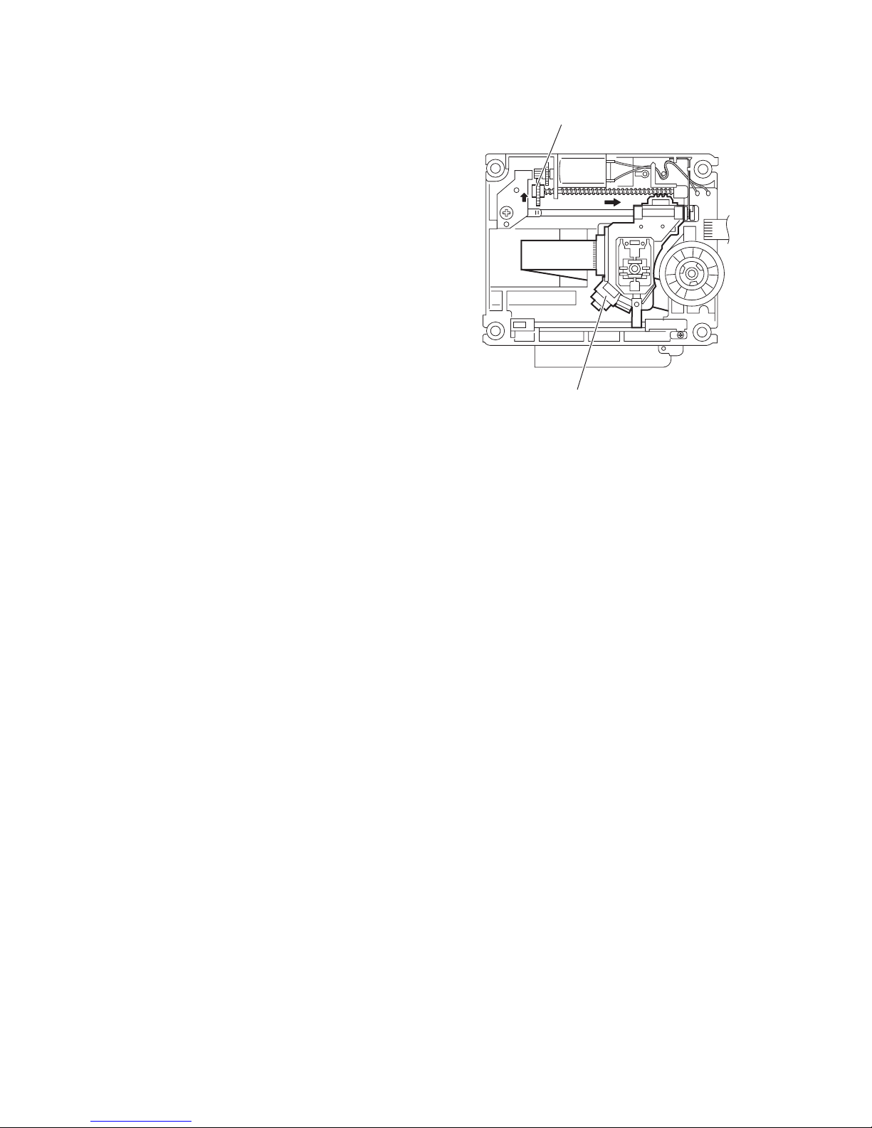
3.2.6 Attaching the DVD pickup
(See Figs.5, 7 to 10)
• See "3.3.5 Removing the DVD pickup".
(1) Attach the guide shaft, rack arm and rack arm spring to the
DVD pickup. (See Fig.9.)
(2) Align the DVD pickup to the section j of the traverse mech-
anism assembly first, and set the both ends of the guide
shaft of the DVD pickup in the sections (g, h) of the
traverse mechanism assembly. (See Fig.8.)
Reference:
When attaching the guide shaft to the section h, attach it
under the rod spring. (See Fig.8.)
(3) Attach the guide shaft adj. spring and feed bracket. (See
Fig.7.)
(4) Remove solders from the short land sections b on the DVD
pickup after connecting the card wire to the connector on
the DVD pickup. (See Fig.5.)
(5) Turn the screw shaft gear in the direction of the arrow 1 to
move the DVD pickup fully in the direction of the arrow 2.
(See Fig.10.)
Screw shaft gear
1
2
DVD pickup
Fig.10
1-20 (No.MB544)
 Loading...