

Page 1

SERVICE MANUAL
COMPACT COMPONENT SYSTEM
MB39920056
EX-D1
Area suffix
B ------------------------------ U.K.
E ---------- Continental Europe
EN ----------- Northern Europe
EV ------------- Eastern Europe
EE -------- Russian Federation
CA-EXD1SP-EXD1 SP-EXD1
Lead free solder used in the board (material : Sn-Ag-Cu, melting point : 219 Centigrade)
TABLE OF CONTENTS
1 PRECAUTION. . . . . . . . . . . . . . . . . . . . . . . . . . . . . . . . . . . . . . . . . . . . . . . . . . . . . . . . . . . . . . . . . . . . . . . . . 1-3
2 SPECIFIC SERVICE INSTRUCTIONS . . . . . . . . . . . . . . . . . . . . . . . . . . . . . . . . . . . . . . . . . . . . . . . . . . . . . . 1-7
3 DISASSEMBLY . . . . . . . . . . . . . . . . . . . . . . . . . . . . . . . . . . . . . . . . . . . . . . . . . . . . . . . . . . . . . . . . . . . . . . . 1-8
4 ADJUSTMENT . . . . . . . . . . . . . . . . . . . . . . . . . . . . . . . . . . . . . . . . . . . . . . . . . . . . . . . . . . . . . . . . . . . . . . . 1-25
5 TROUBLESHOOTING . . . . . . . . . . . . . . . . . . . . . . . . . . . . . . . . . . . . . . . . . . . . . . . . . . . . . . . . . . . . . . . . . 1-35
COPYRIGHT © 2005 Victor Company of Japan, Limited
No.MB399
2005/6
Page 2
SPECIFICATION
General Power source AC 230 V , 50 Hz
Power consumption 25 W (in operation)
1.0 W (on standby)
Weight 3.0 kg
External dimensions (W × H × D) 150 mm × 152 mm × 246 mm
DVD player Playable discs DVD VIDEO, DVD AUDIO, VCD,
SVCD, CD, CD-R/RW (CD, VCD,
MP3, WMA, JPEG format), DVD-R/-RW (video format)
Video output Color system PAL
Horizontal resolution 500 lines
Composite × 1 1.0 V (p-p)/75 Ω, synchronization negative
S-video × 1 Y output: 1.0 V (p-p)/75 Ω, synchronization negative
C output: 0.3 V (p-p)/75 Ω
Component × 1 Y output: 1.0 V (p-p)/75 Ω, synchronization negative
PB/PR output: 0.7 V (p-p)/75 Ω
Audio output Analog sound output Speakers × 2 Output power (IEC 268-3): 36 W (18 W+18 W) at 4 Ω (10% THD)
Fitting impedance: 4 Ω to 16 Ω
Headphones × 1 11 mW/32 Ω
Fitting impedance: 16 Ω to 1 kΩ
Subwoofer × 1 500 mVrms/10 kΩ
Digital sound output Optical × 1 -21 dBm to -15 dBm
Audio input Sound input AUX × 1
400 mV/50 kΩ
USB AUDIO × 1
Tuner FM tuner Receiving frequency 87.50 MHz to 108.00 MHz
Antenna 75 Ω- Unbalanced type
AM (MW) tuner Receiving frequency 522 kHz to 1 629 kHz
Antenna External antenna jack (loop antenna)
Speaker Type Full range
1-way bass-reflex type
Magnetically shielded type
Speaker 8cm cone × 1
Frequency response 55 to 20 000 Hz
Power handling capacity 30 W
Impedance 4Ω
Sound pressure level 80 dB/W m
Dimension (W × H × D) 120 mm × 151 mm × 241 mm
Weight 1.8 kg each
Designs and Specifications are subject to change without notice.
1-2 (No.MB399)
Page 3
SECTION 1
PRECAUTION
1.1 Safety Precautions
(1) This design of this product contains special hardware and
many circuits and components specially for safety purposes. For continued protection, no changes should be made
to the original design unless authorized in writing by the
manufacturer. Replacement parts must be identical to
those used in the original circuits. Services should be performed by qualified personnel only.
(2) Alterations of the design or circuitry of the product should
not be made. Any design alterations of the product should
not be made. Any design alterations or additions will void
the manufacturers warranty and will further relieve the
manufacture of responsibility for personal injury or property
damage resulting therefrom.
(3) Many electrical and mechanical parts in the products have
special safety-related characteristics. These characteristics are often not evident from visual inspection nor can the
protection afforded by them necessarily be obtained by using replacement components rated for higher voltage, wattage, etc. Replacement parts which have these special
safety characteristics are identified in the Parts List of Service Manual. Electrical components having such features
are identified by shading on the schematics and by ( ) on
the Parts List in the Service Manual. The use of a substitute
replacement which does not have the same safety characteristics as the recommended replacement parts shown in
the Parts List of Service Manual may create shock, fire, or
other hazards.
(4) The leads in the products are routed and dressed with ties,
clamps, tubings, barriers and the like to be separated from
live parts, high temperature parts, moving parts and/or
sharp edges for the prevention of electric shock and fire
hazard. When service is required, the original lead routing
and dress should be observed, and it should be confirmed
that they have been returned to normal, after reassembling.
(5) Leakage shock hazard testing
After reassembling the product, always perform an isolation check on the exposed metal parts of the product (antenna terminals, knobs, metal cabinet, screw heads,
headphone jack, control shafts, etc.) to be sure the product
is safe to operate without danger of electrical shock.Do not
use a line isolation transformer during this check.
• Plug the AC line cord directly into the AC outlet. Using a
"Leakage Current Tester", measure the leakage current
from each exposed metal parts of the cabinet, particularly any exposed metal part having a return path to the
chassis, to a known good earth ground. Any leakage current must not exceed 0.5mA AC (r.m.s.).
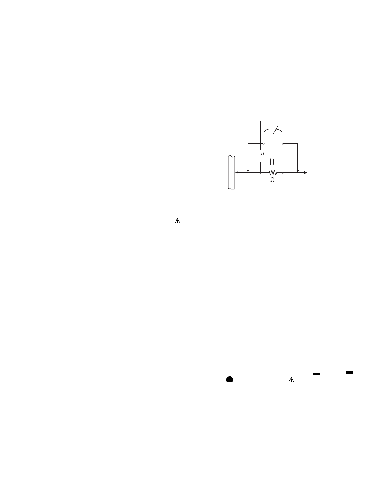
• Alternate check method
Plug the AC line cord directly into the AC outlet. Use an
AC voltmeter having, 1,000Ω per volt or more sensitivity
in the following manner. Connect a 1,500Ω 10W resistor
paralleled by a 0.15µF AC-type capacitor between an ex-
posed metal part and a known good earth ground.
Measure the AC voltage across the resistor with the AC
voltmeter.
Move the resistor connection to each exposed metal
part, particularly any exposed metal part having a return
path to the chassis, and measure the AC voltage across
the resistor. Now, reverse the plug in the AC outlet and
repeat each measurement. Voltage measured any must
not exceed 0.75 V AC (r.m.s.). This corresponds to 0.5
mA AC (r.m.s.).
AC VOLTMETER
(Having 1000
ohms/volts,
or more sensitivity)
0.15 F AC TYPE
Place this
probe on
1500 10W
Good earth ground
1.2 Warning
(1) This equipment has been designed and manufactured to
meet international safety standards.
(2) It is the legal responsibility of the repairer to ensure that
these safety standards are maintained.
(3) Repairs must be made in accordance with the relevant
safety standards.
(4) It is essential that safety critical components are replaced
by approved parts.
(5) If mains voltage selector is provided, check setting for local
voltage.
1.3 Caution
Burrs formed during molding may be left over on some parts
of the chassis.
Therefore, pay attention to such burrs in the case of preforming repair of this system.
1.4 Critical parts for safety
In regard with component parts appearing on the silk-screen
printed side (parts side) of the PWB diagrams, the parts that are
printed over with black such as the resistor ( ), diode ( )
and ICP ( ) or identified by the " " mark nearby are critical
for safety. When replacing them, be sure to use the parts of the
same type and rating as specified by the manufacturer.
(This regulation dose not Except the J and C version)
each exposed
metal part.
(No.MB399)1-3
Page 4
1.5 Safety Precautions (U.K only)
(1) This design of this product contains special hardware and many circuits and components specially for safety purposes. For con-
tinued protection, no changes should be made to the original design unless authorized in writing by the manufacturer. Replacement parts must be identical to those used in the original circuits.
(2) Any unauthorised design alterations or additions will void the manufacturer's guarantee; furthermore the manufacturer cannot
accept responsibility for personal injury or property damage resulting therefrom.
(3) Essential safety critical components are identified by ( ) on the Parts List and by shading on the schematics, and must never
be replaced by parts other than those listed in the manual. Please note however that many electrical and mechanical parts in
the product have special safety related characteristics. These characteristics are often not evident from visual inspection. Parts
other than specified by the manufacturer may not have the same safety characteristics as the recommended replacement parts
shown in the Parts List of the Service Manual and may create shock, fire, or other hazards.
(4) The leads in the products are routed and dressed with ties, clamps, tubings, barriers and the like to be separated from live parts,
high temperature parts, moving parts and/or sharp edges for the prevention of electric shock and fire hazard. When service is
required, the original lead routing and dress should be observed, and it should be confirmed that they have been returned to
normal, after re-assembling.
1.5.1 Warning
(1) Service should be performed by qualified personnel only.
(2) This equipment has been designed and manufactured to meet international safety standards.
(3) It is the legal responsibility of the repairer to ensure that these safety standards are maintained.
(4) Repairs must be made in accordance with the relevant safety standards.
(5) It is essential that safety critical components are replaced by approved parts.
(6) If mains voltage selector is provided, check setting for local voltage.
Burrs formed during molding may be left over on some parts of the chassis. Therefore,
pay attention to such burrs in the case of preforming repair of this system.
1-4 (No.MB399)
Page 5
1.6 Preventing static electricity
Electrostatic discharge (ESD), which occurs when static electricity stored in the body, fabric, etc. is discharged, can destroy the laser
diode in the traverse unit (optical pickup). Take care to prevent this when performing repairs.
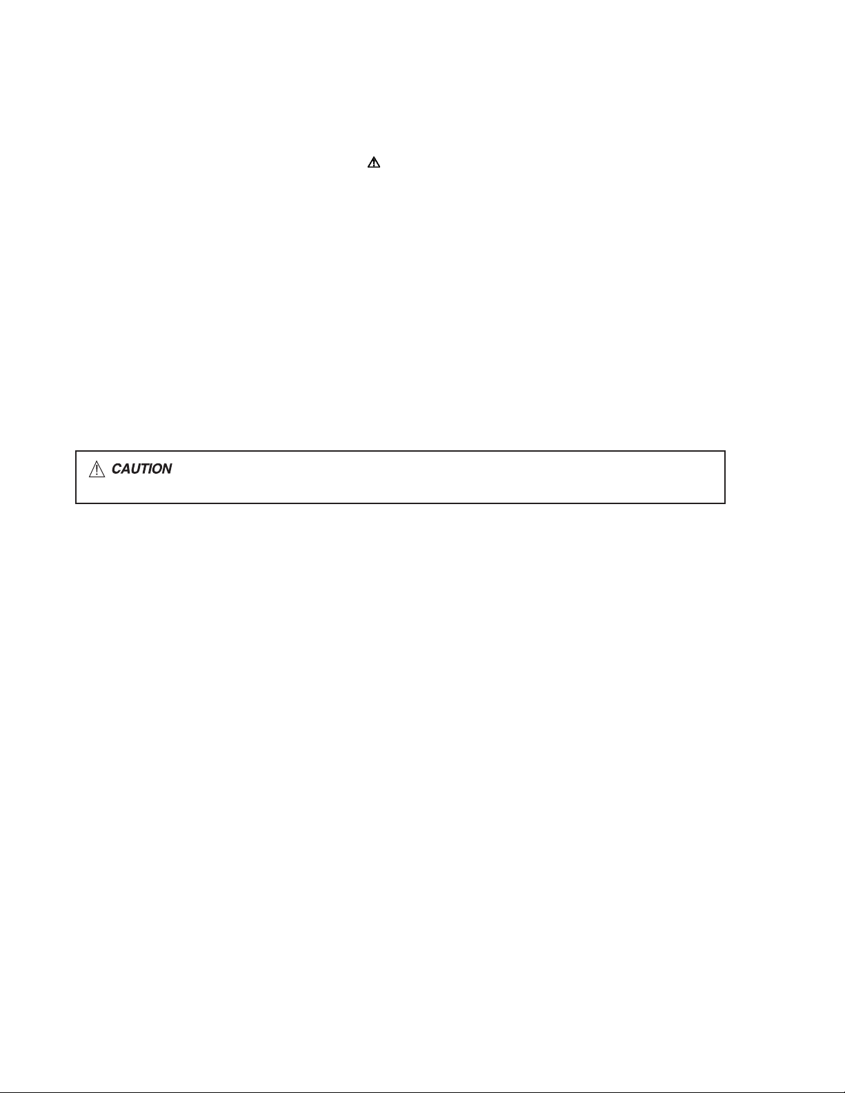
1.6.1 Grounding to prevent damage by static electricity
Static electricity in the work area can destroy the optical pickup (laser diode) in devices such as laser products.
Be careful to use proper grounding in the area where repairs are being performed.
(1) Ground the workbench
Ground the workbench by laying conductive material (such as a conductive sheet) or an iron plate over it before placing the
traverse unit (optical pickup) on it.
(2) Ground yourself
Use an anti-static wrist strap to release any static electricity built up in your body.
(caption)
Anti-static wrist strap
1M
Conductive material
(conductive sheet) or iron palate
(3) Handling the optical pickup
• In order to maintain quality during transport and before installation, both sides of the laser diode on the replacement optical
pickup are shorted. After replacement, return the shorted parts to their original condition.
(Refer to the text.)
• Do not use a tester to check the condition of the laser diode in the optical pickup. The tester's internal power source can easily
destroy the laser diode.
1.7 Handling the traverse unit (optical pickup)
(1) Do not subject the traverse unit (optical pickup) to strong shocks, as it is a sensitive, complex unit.
(2) Cut off the shorted part of the flexible cable using nippers, etc. after replacing the optical pickup. For specific details, refer to the
replacement procedure in the text. Remove the anti-static pin when replacing the traverse unit. Be careful not to take too long a
time when attaching it to the connector.
(3) Handle the flexible cable carefully as it may break when subjected to strong force.
(4) I t is not possible to adjust the semi-fixed resistor that adjusts the laser power. Do not turn it.
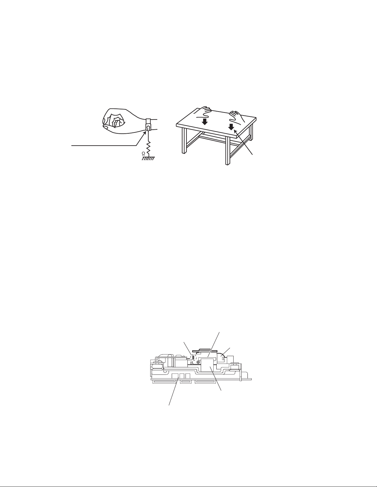
1.8 Attention when traverse unit is decomposed
*Please refer to "Disassembly method" in the text for the pickup unit.
• Apply solder to the short land sections before the flexible wire is disconnected from the connecto on the servo board. (If the flexible
wire is disconnected without applying solder, the pickup may be destroyed by static electricity.)
• In the assembly, be sure to remove solder from the short land sections after connecting the flexible wire.
Connector
Short land section
Pickup
Card wire
Traverse mechanism assembly
(No.MB399)1-5
Page 6

1.9 Important for laser products
!
1.CLASS 1 LASER PRODUCT
2.DANGER : Invisible laser radiation when open and inter
lock failed or defeated. Avoid direct exposure to beam.
3.CAUTION : There are no serviceable parts inside the
Laser Unit. Do not disassemble the Laser Unit. Replace
the complete Laser Unit if it malfunctions.
4.CAUTION : The CD,MD and DVD player uses invisible
laser radiation and is equipped with safety switches which
prevent emission of radiation when the drawer is open and
the safety interlocks have failed or are defeated. It is
dangerous to defeat the safety switches.
5.CAUTION : If safety switches malfunction, the laser is able
to function.
6.CAUTION : Use of controls, adjustments or performance of
procedures other than those specified here in may result in
hazardous radiation exposure.
Please use enough caution not to
see the beam directly or touch it
in case of an adjustment or operation
check.
REPRODUCTION AND POSITION OF LABELS
WARNING LABEL
CAUTION : Visible and Invisible
laser radiation when open and
interlock failed or defeated.
AVOID DIRECT EXPOSURE TO
BEAM. (e)
CLASS 1
LASER PRODUCT
ADVARSEL : Synlig og usynlig
laserstråling når maskinen er
åben eller interlocken fejeler.
Undgå direkte eksponering til
stråling. (d)
CAUTION : Visible and Invisible
laser radiation when open and
interlock failed or defeated.
AVOID DIRECT EXPOSURE TO
BEAM. (e)
VARNING : Synlig och
osynling laserstrålning när
den öppnas och spärren är
urkopplad. Betrakta ej
strålen. (s)
VARNING : Synlig och
osynling laserstrålning när
den öppnas och spärren är
urkopplad. Betrakta ej
strålen. (s)
VARO : Avattaessa ja suojalukitus
ohitettuna tai viallisena olet alttiina
näkyvälle ja näkymättömälle
lasersäteilylle. Vältä säteen
kohdistumista suoraan itseesi. (f)
ADVARSEL : Synlig og usynlig
laserstråling når maskinen er
åben eller interlocken fejeler.
Undgå direkte eksponering til
stråling. (d)
VARO : Avattaessa ja suojalukitus
ohitettuna tai viallisena olet alttiina
näkyvälle ja näkymättömälle
lasersäteilylle. Vältä säteen
kohdistumista suoraan itseesi. (f)
1-6 (No.MB399)
Page 7

SECTION 2
SPECIFIC SERVICE INSTRUCTIONS
This service manual does not describe SPECIFIC SERVICE INSTRUCTIONS.
(No.MB399)1-7
Page 8
SECTION 3
DISASSEMBLY
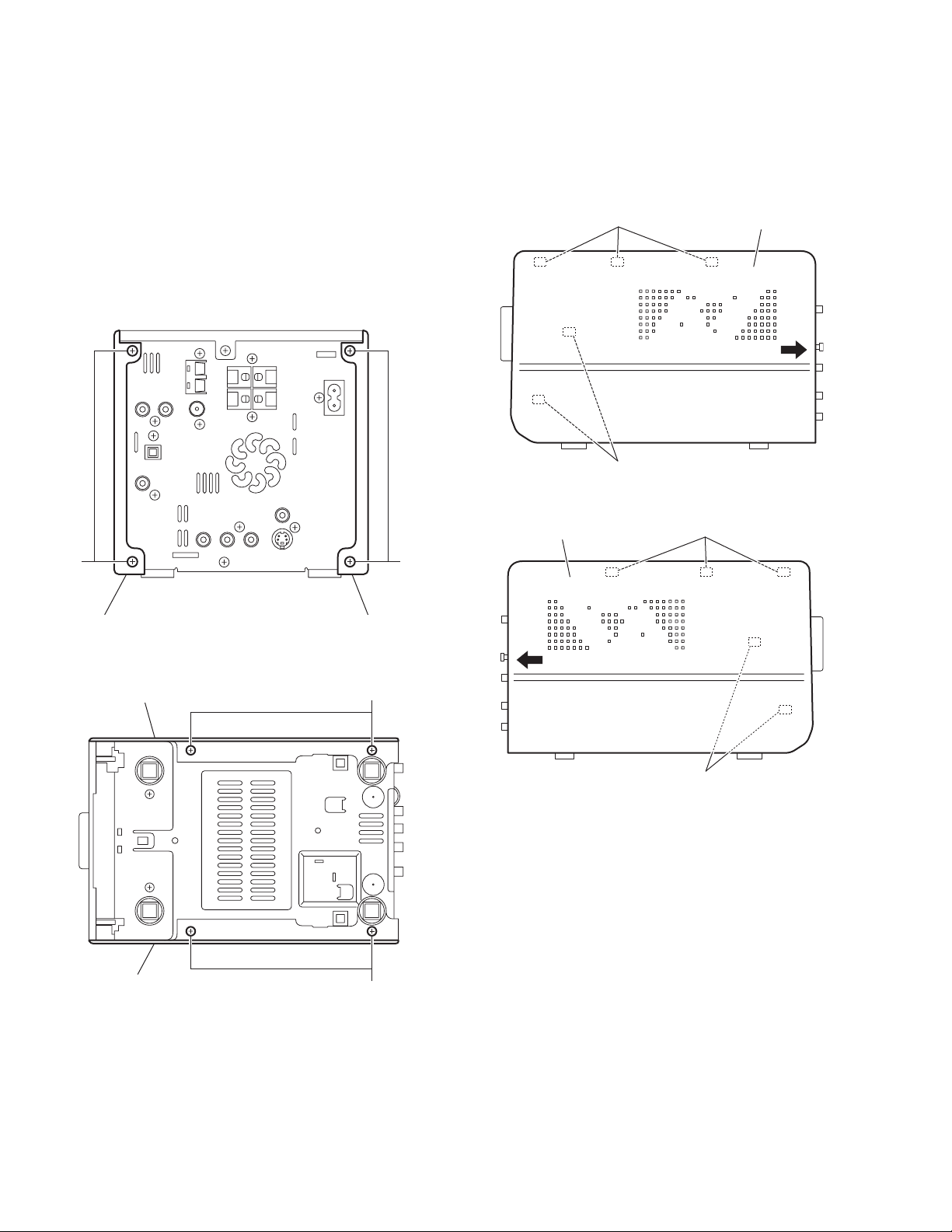
3.1 Main body section
3.1.1 Removing the side panel L and side panel R
(See Figs.1 to 4)
(1) From the back side of the main body, remove the four
screws A attaching the side panels L/R. (See Fig.1.)
(2) From the bottom side of the main body, remove the four
screws B attaching the side panels L/R. (See Fig.2.)
(3) From the both sides of the main body, release the joint a in
the direction of the arrow and remove the side panels L/R
toward this side. (See Figs.3 and 4.)
a
a
Fig.3
Side panel R
A A
Side panel R Side panel L
Fig.1
Side panel R
B
Side panel L
a
a
Fig.4
Side panel L
1-8 (No.MB399)
B
Fig.2
Page 9
3.1.2 Removing the top panel assembly
(See Figs.5 to 6)
• Remove the side panels L/R.
(1) From the front side of the main body, pull out the volume
knob assembly in the direction of the arrow. (See Fig.5.)
(2) Remove the two screws C and remove the volume orna-
ment. (See Fig.5.)
(3) From the both sides of the main body, remove the two
screws D, two screws E and screw F. (See Figs.5 and 6)
Reference:
When attaching the screw F, attach the earth wire with it.
(See Fig.6.)
(4) From the back side of the main body, remove the screw G
attaching the top panel assembly. (See Fig.6.)
(5) From the both sides of the main body, release the joints b
and remove the joints c in the direction of the arrow. (See
Figs.5 and 6.)
(6) Disconnect the card wire from the connector CN427
micom board while lifting the top panel assembly. (See
Fig.5.)
on the
Volume knob assembly
D
c
C
Volume ornament
C
Top panel assembly
CN427
Fig.5
E
Micom board
b
Top panel assembly
G
E
b
Top panel assembly
Earth wire
F
Fig.6
D
c
(No.MB399)1-9
Page 10
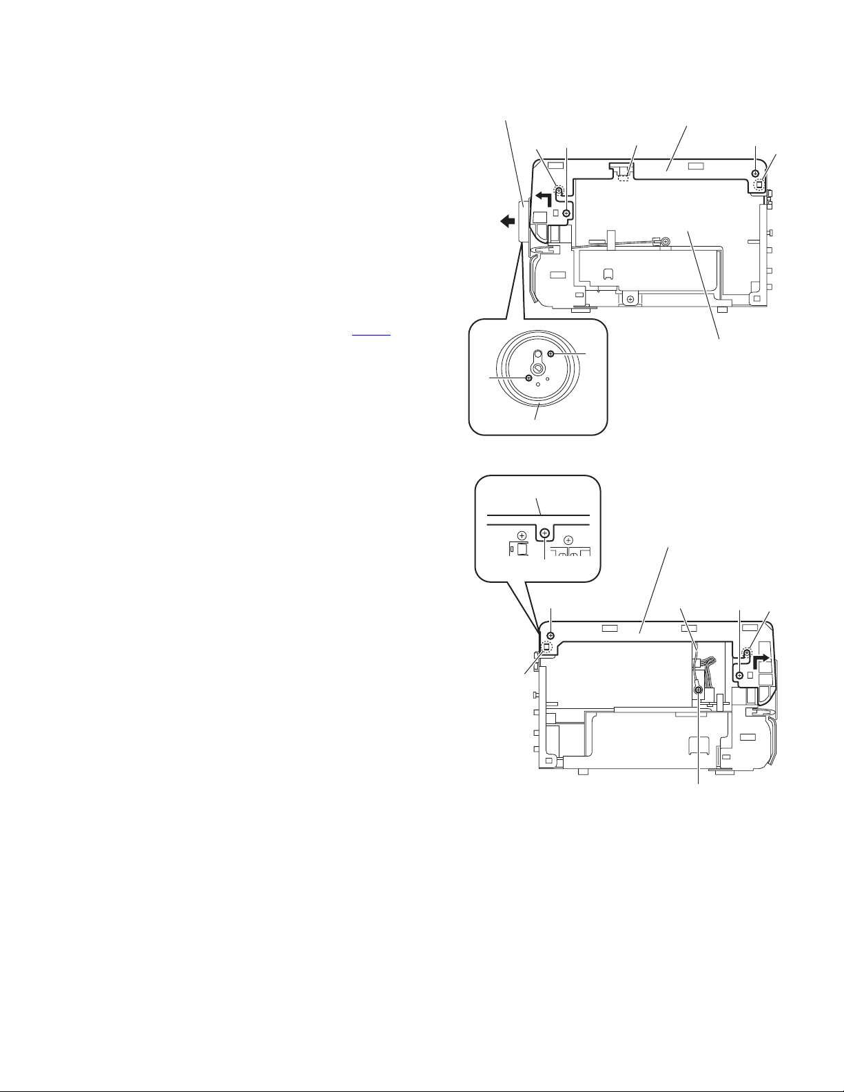
3.1.3 Removing the front panel assembly
(See Figs.7 to 9)
• Remove the side panels L/R and top panel assembly.
(1) From the bottom side of the main body, remove the two
screws H attaching the front panel assembly. (See Fig.7.)
(2) From the forward side of the micom board, disconnect the
card wire from the connector CN426
(3) Disconnect the wire from the connector CN501 on the mi-
com board. (See Fig.8.)
(4) From the right side of the main body, remove the screw J
and remove the earth wire. (See Fig.8.)
Reference:
• When attaching the screw J, attach the earth wire with
it. (See Fig.8.)
• After attaching the earth wire, fix it with the spacers as
before. (See Fig.8.)
(5) From the left side of the main body, remove the screw K
and remove the earth wire. (See Fig.9.)
Reference:
When attaching the screw K, attach the earth wire with
it. (See Fig.9.)
(6) From the bottom and both sides of the main body, release
the joints (d, e) of the front panel assembly and remove the
front panel assembly in the direction of the arrow. (See
Figs.7 to 9.)
Front panel assembly
. (See Fig.8.)
d
Front panel assembly
CN501
e
Micom board
CN426
Spacers
Fig.8
Front panel assembly
Earth wire
J
H
H
Fig.7
e
Earth wire
K
Fig.9
1-10 (No.MB399)
Page 11
3.1.4 Removing the tuner
(See Figs.10 and 11)
• Remove the side panels L/R and top panel assembly.
(1) From the back side of the main body, remove the two
screws M attaching the tuner to the rear panel. (See
Fig.10.)
(2) Disconnect the card wire from the connector CN1
tuner. (See Fig.11.)
on the
M
Tuner
M
Fig.10
CN1
Tuner
Fig.11
(No.MB399)1-11
Page 12

3.1.5 Removing the rear panel
(See Fig.12)
• Remove the side panels L/R and top panel assembly.
(1) From the back side of the main body, remove the ten
screws N and screw P attaching the rear panel.
(2) From the top side of the main body, disconnect the earth
wire from the rear panel in the direction of the arrow.
(3) From the both sides of the main body, release the joints f
and remove the rear panel.
Earth wire
Rear panel
N
N
Rear panel
P
N
ff
N
Fig.12
1-12 (No.MB399)
Page 13

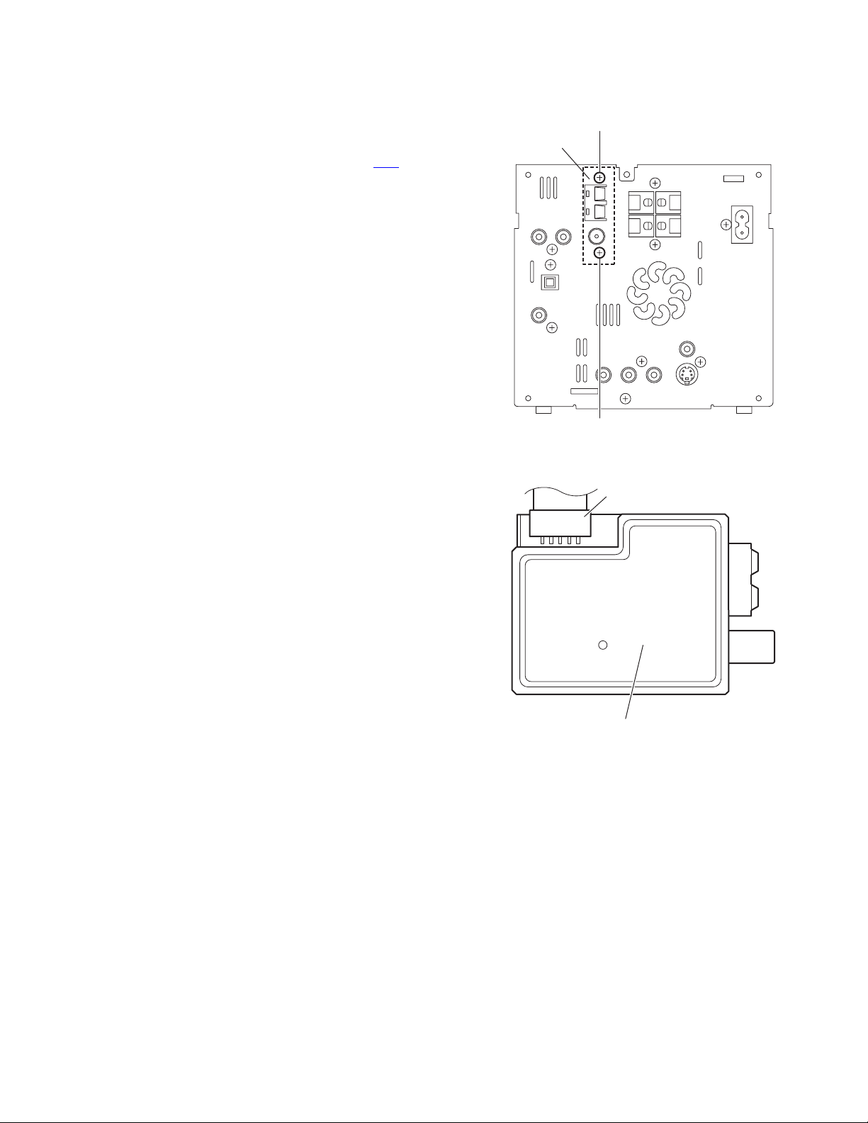
3.1.6 Removing the switching power supply
(See Figs.13 and 14)
• Remove the side panels L/R, top panel assembly and rear
panel.
(1) From the top side of the main body, disconnect the wire
from the connector CN200
Fig.13.)
(2) Take out the switching power supply in the direction of the
arrow. (See Fig.14.)
on the regulator board. (See
Regulator board
CN200
Fig.13
Switching power supply
Fig.14
(No.MB399)1-13
Page 14

3.1.7 Removing the digital amplifier board assembly
(See Figs.15 and 16)
• Remove the side panels L/R, top panel assembly, rear panel
and switching power supply.
(1) From the top side of the main body, remove the screw Q
attaching the digital amplifier board assembly. (See
Fig.15.)
(2) From the left side of the main body, disconnect the connec-
tors (CN310
assembly from the regulator board. (See Fig.16.)
(3) Release the joint g of the shield case B in the direction of
the arrow and take out the digital amplifier board assembly
from the main body. (See Fig.16.)
, CN311, CN312) on the digital amplifier board
Digital amplifier board assembly
Q
Fig.15
Digital amplifier board assembly
Regulator board
Shield case B
1-14 (No.MB399)
CN312 CN311 CN310
g
Fig.16
Page 15

3.1.8 Removing the digital amplifier board
(See Figs.17 to 22)
• Remove the side panels L/R, top panel assembly, rear panel,
switching power supply and digital amplifier board assembly.
(1) From the forward side of the digital amplifier board assem-
bly, remove the screw R. (See Fig.17.)
(2) From the top and bottom sides of the digital amplifier board
assembly, remove the three screws S. (See Figs.18 and
19.)
(3) Release the joints (h, j, k, m) and remove the shield case
B with the heat sink in the direction of the arrow. (See
Figs.18 to 21.)
(4) From the forward side of the digital amplifier board, remove
the screw S attaching the heat sink. (See Fig.22.)
(5) Remove the solders from the soldered sections (n, p) and
bend the sections (q, r) of the shield case A in the direction
of the arrow. (See Fig.22.)
(6) Take out the digital amplifier board from the shield case A.
Heat sink
Shield case B
k
Fig.20
Digital amplifier board assembly
R
Fig.17
Shield case B
Digital amplifier board assembly
Shield case B
S
hh
Fig.18
Heat sink
Heat sink
SS
Shield case B
m
Fig.21
q
n
Heat sink
S
Digital amplifier board
Fig.22
Heat sink
Shield case A
p
r
j
Digital amplifier board assembly
Fig.19
(No.MB399)1-15
Page 16

3.1.9 Removing the micom board
(See Fig.23)
• Remove the side panels L/R, top panel assembly and rear
panel.
(1) From the right side of the main body, remove the screw T
attaching the micom board.
Reference:
• When attaching the screw T, attach the earth wire with
it.
• After attaching the earth wire, fix it with the spacers as
before.
(2) Disconnect the card wire from the connector CN421
forward side of the micom board.
Reference:
Remove the tuner as required. (See Figs.10 and 11.)
(3) Disconnect the card wire from the connector CN426
forward side of the micom board.
(4) Disconnect the wire from the connector CN501
ward side of the micom board.
(5) Disconnect the connectors (CN423
the micom board from the regulator and video boards toward this side to remove the micom board.
3.1.10 Removing the regulator board
(See Fig.24)
• Remove the side panels L/R, top panel assembly, tuner, rear
panel, switching power supply, digital amplifier board assembly and micom board.
(1) From the top side of the main body, disconnect the card
wires from the connectors (CN208
tor board.
Reference:
When connecting the card wire to the connector CN208
pass it through the hole s of the regulator board as before.
(2) Remove the two screws U and screw U'.
Reference:
When attaching the screw U', attach the wire holder with
it.
(3) Remove the screw V' to remove the earth wire and take out
the regulator board.
3.1.11 Removing the video board
(See Fig.24)
• Remove the side panels L/R, top panel assembly, tuner, rear
panel, switching power supply, digital amplifier board assembly and micom board.
Reference:
Remove the regulator board as required.
(1) From the top side of the main body, remove the screws V
and screw V'.
Reference:
When attaching the screw V', attach the earth wire with
it.
(2) Take out the video board in the direction of the arrow.
(3) Disconnect the card wire from the connector CN703
video board.
, CN424, CN425) on
, CN210) on the regula-
on the
on the
on the for-
on the
Micom board
CN501
CN210
,
CN426
Spacers
Regulator board
U'
Wire holder
Earth wire
CN424
Fig.23
Fig.24
CN421
CN423
T
Video board
U
CN208
U
Earth wire
CN425
V
CN703
s
V'
1-16 (No.MB399)
Page 17

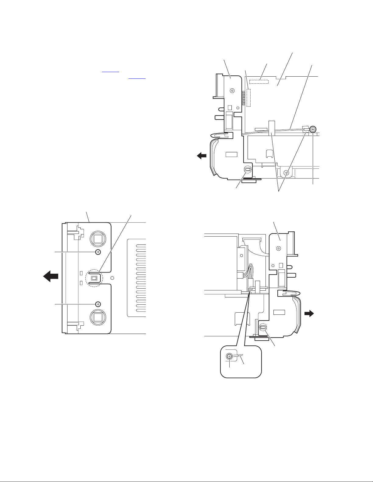
3.1.12 Removing the DVD mechanism assembly
(See Figs.25 to 28)
• Remove the side panels L/R, top panel assembly, front panel
assembly, tuner, rear panel, switching power supply, digital
amplifier board assembly, micom board and regulator board.
(1) From the right side of the main body, remove the screw W
attaching the metal chassis. (See Fig.25.)
(2) From the top side of the main body, remove the two screws
X and take out the metal chassis. (See Fig.26.)
Reference:
When attaching the metal chassis, pass the card wire
through the hole t on the metal chassis as before.
(3) Disconnect the card wire from the connector CN703
video board. (See Fig.27.)
(4) Remove the screw Y and take out the DVD mechanism as-
sembly from the bottom chassis. (See Fig.27.)
Reference:
When the resolution of DVD mechanism assembly is done sequentially, remove a CD fitting in the direction of the arrow.
(See Fig.28.)
on the
DVD mechanism assembly
Bottom chassis
Video board
Y
CN703
Metal chassis
CD fitting
W
Fig.25
t
Metal chassis
X
Fig.27
DVD mechanism assembly
Fig.28
Fig.26
X
(No.MB399)1-17
Page 18

3.1.13 Removing the switch board
(See Fig.29)
• Remove the side panels L/R and top panel assembly.
From the inside of the top panel assembly, remove the three
screws Z and take out the switch board.
Top panel assembly
3.1.14 Removing the front board
(See Fig.30)
• Remove the side panels L/R, top panel and front panel assem-
blies.
(1) From the inside of the front panel assembly, disconnect the
card wire from the connector CN605
(2) Remove the five screws AA and take out the front board.
3.1.15 Removing the FL board
(See Fig.30)
• Remove the side panels L/R, top panel assembly, front panel
assembly and front board.
Remove the two screws AA and take out the FL board.
3.1.16 Removing the headphone and USB board
(See Fig.30)
• Remove the side panels L/R, top panel and front panel assem-
blies.
(1) Remove the four screws AA and take out the support
boards.
(2) Take out the headphone and USB board.
Reference:
After attaching the headphone and USB board, fix the wires
with the spacers as before.
on the front board.
Z
Front board
AA
AA
Spacer
Support board
Switch board
Fig.29
AA
AA
AA
Z
FL board
CN605
AA
AA
Spacer
Support board
1-18 (No.MB399)
Headphone and USB board
Fig.30
Page 19

3.2 DVD mechanism section
• Remove the DVD mechanism assembly from the main body.
(See "Removing the DVD mechanism assembly".)
3.2.1 Removing the clamper base
(See Fig.1)
(1) From the top side of the DVD mechanism assembly, re-
move the two screws A attaching the clamper base.
(2) Lift the clamper base in an upward direction to remove it
from the projections a of the DVD mechanism assembly.
(3) Slide the clamper base in the direction of the arrow and re-
move it from the joints b.
Clamper base
A
a
b
3.2.2 Removing the tray assembly
(See Fig.2)
(1) From the top side of the DVD mechanism assembly, re-
move the two screws B attaching the shaft guide of the tray
assembly.
(2) Remove the tray assembly from the projections c of the
DVD mechanism assembly and take out the tray assembly.
a
A
DVD mechanism assembly
Tray assembly
b
Fig.1
DVD mechanism assembly
Shaft guide
cc
B
Fig.2
(No.MB399)1-19
Page 20

3.2.3 Removing the traverse mechanism assembly
(See Figs.3)
(1) From the bottom side of the DVD mechanism assembly, re-
move the four screws C attaching the traverse mechanism
assembly.
(2) Take out the traverse mechanism assembly with the DVD
module board.
DVD mechanism assembly
DVD module board
3.2.4 Removing the DVD module board
(See Figs.4 and 5)
• Remove the traverse mechanism assembly.
(1) From the side of the traverse mechanism assembly, solder
the short land sections d on the pickup. (See Fig.4.)
(2) From the bottom side of the traverse mechanism assem-
bly, release the lock of the connector CN101
module board in the direction of the arrow 1 and disconnect
the card wire. (See Fig.5.)
Caution:
• Solder the short land sections d on the pickup before
disconnecting the card wire from the connector CN101
on the DVD module board. If the card wire is disconnected without attaching solder, the pickup may be destroyed by static electricity. (See Figs.4 and 5.)
• When attaching the DVD module board, be sure to remove solders from the short land sections d after connecting the card wire to the connector CN101
DVD module board. (See Figs.4 and 5.)
(3) Disconnect the card wire from the connector CN201
DVD module board. (See Fig.5.)
(4) Remove the two screws D attaching the DVD module
board. (See Fig.5.)
(5) Remove the DVD module board from the projection e in an
upward direction and remove the engagement section g in
the direction 3 while removing the engagement section f in
the direction of the arrow 2. (See Fig.5.)
on the DVD
on the
on the
C
Traverse mechanism assembly
Fig.3
d
Traverse mechanism assembly
Fig.4
e
D
Card wire
11
2
Card wire
CN101
C
Pickup
CN201
D
g
3
1-20 (No.MB399)
f
DVD module board
Traverse mechanism assembly
Fig.5
Page 21

3.2.5 Removing the pickup
(See Figs.4,6 to 8)
• Remove the traverse mechanism assembly.
(1) From the side of the traverse mechanism assembly, solder
the short land sections d on the pickup. (See Fig.4.)
(2) Release the lock of the connector on the pickup in the di-
rection of the arrow and disconnect the card wire. (See
Fig.6.)
Caution:
• Solder the short land sections d on the pickup before
disconnecting the card wire from the connector on the
pickup. If the card wire is disconnected without attaching solder, the pickup may be destroyed by static electricity. (See Figs.4 and 6.)
• When attaching the pickup, be sure to remove solders
from the short land sections d after connecting the
card wire to the connector on the pickup. (See Figs.4
and 6.)
(3) Remove the screw E attaching the plate and thrust spring.
(See Fig.6.)
(4) Remove the engagement section h attaching the plate to
the feed holder and remove the plate. (See Fig.6.)
(5) Remove the engagement sections (i, j), remove the thrust
spring. (See Fig.6.)
(6) Remove the shaft of the pickup from the section k on the
traverse mechanism assembly and remove the shaft from
the section m while moving it in the direction of the arrow.
(See Fig.7.)
(7) Remove the pickup from the section n of the traverse
mechanism assembly and take out the pickup with the
shaft. (See fig.7.)
(8) From the bottom side of the pickup, remove the two screws
F attaching the SW actuator and lead spring. (See Fig.8.)
(9) Pull the shaft out of the pickup. (See Fig.8.)
i
Thrust spring
Plate
E
j
Thrust spring
h
Card wire
Traverse mechanism assembly
Feed holder
Connector
Fig.6
Traverse mechanism assembly
Pickup
k
Shaft
Pickup
Fig.7
Torsion spring
m
n
(No.MB399)1-21
Page 22

3.2.6 Attaching the pickup
(See Figs.4,6 to 9)
• See "3.2.5 Removing the pickup".
(1) Attach the shaft, SW actuator and lead spring to the pickup.
(See Fig.8.)
(2) Align the pickup to the section n of the traverse mechanism
assembly first and set the both ends of the shaft of the pickup in the sections (k, m) of the traverse mechanism assembly. (See Fig.7.)
Note:
When attaching the shaft to the section m, attach it under
the torsion spring. (See Fig.7.)
(3) Attach the plate and thrust spring. (See Fig.6.)
(4) Remove solders from the short land sections d after con-
necting the card wire to the connector on the pickup. (See
Figs.4 and 6.)
(5) Turn the feed gear M in the direction of the arrow 1 to move
the pickup in the direction of the arrow 2. (See Fig.9.)
Shaft
Feed gear M
Fig.8
Pickup
SW actuator
Lead spring
F
1
2
Pickup
Fig.9
1-22 (No.MB399)
Page 23

3.2.7 Removing the feed motor
(See Figs.10 to 12)
• Remove the traverse mechanism assembly.
(1) From the top side of the traverse mechanism assembly, re-
move the screw G attaching the plate and thrust spring.
(See Fig.10.)
(2) Remove the engagement section p attaching the plate to
the feed holder and remove the plate. (See Fig.10.)
(3) Remove the engagement sections (q, r), remove the thrust
spring. (See Fig.10.)
(4) Remove the wires from the soldered section s on the spin-
dle motor board. (See Fig.11.)
Reference:
When attaching the feed motor, pass the wire through
the section t on the spindle base. (See Fig.11.)
(5) Remove the feed holder, feed motor, lead screw, feed gear
E and feed gear M at the same time after removing the
three screws H attaching the feed holder. (See Fig.11.)
(6) From the side of the feed holder, remove the two screws J
attaching the feed motor. (See Fig.12.)
3.2.8 Removing the spindle motor board
(See Figs.11 and 13)
• Remove the traverse mechanism assembly and DVD module
board.
(1) From the top side of the traverse mechanism assembly, re-
move the wires from the soldered section s on the spindle
motor board. (See Fig.11.)
(2) From the bottom side of the traverse mechanism assem-
bly, remove the three screws K attaching the spindle motor
board. (See Fig.13.)
Feed gear M
Feed gear E
H
Feed holder
J
H
Feed motor
Spindle base
Fig.11
Lead screw
Wires
Spindle motor board
Feed holder
t
s
q
Thrust spring
Plate
G
r
Thrust spring
p
Fig.12
Traverse mechanism assembly
Feed holder
Traverse mechanism assembly
K
Fig.13
Fig.10
(No.MB399)1-23
Page 24

3.2.9 Removing the switch board
(See Fig.14.)
(1) From the bottom side of the DVD mechanism assembly, re-
move the screw L attaching the switch board.
(2) Disconnect the card wire from the connector CN1 on the
switch board.
(3) Remove the wires from the soldered section u on the
switch board.
(4) Lift the switch board while pressing the claw v of the DVD
mechanism assembly in the direction of the arrow and remove it from the section w.
Reference:
Put the wires on the section x after attaching the switch board
to the DVD mechanism assembly.
3.2.10 Removing the motor
(See Figs.14 and 15)
• Remove the clamper base and tray assembly.
(1) From the bottom side of the DVD mechanism assembly, re-
move the wires from the soldered section u on the switch
board. (See Fig.14.)
(2) From the top side of the DVD mechanism assembly, re-
move the belt from the motor pulley. (See Fig.15.)
Note:
Take care not to attach grease on the belt.
(3) Remove the two screws M attaching the motor to the DVD
mechanism assembly and take out the motor from the bottom side of the DVD mechanism assembly. (See Fig.15.)
Reference:
Put the wires on the section x after attaching the motor to the
DVD mechanism assembly. (See Fig.14.)
Card wire
L
M
Switch board
CN1
w
x
u
v
Wires
DVD mechanism assembly
Fig.14
Motor pulley
Belt
DVD mechanism assembly
Fig.15
1-24 (No.MB399)
Page 25

4.1 Service mode
4.1.1 Confirming contents
(1) Tuner AM switch to 9kHz-step
(2) Tuner AM switch to 10kHz-step
(3) Cold start
(4) Tray lock
(5) DVD test mode
(6) DVD initialize
4.1.2 Confirming methods
SECTION 4
ADJUSTMENT
1. Tuner AM switch to 9kHz-step
AM frequency change to 9kHz at U & A-version.
Press the [
main unit and set the tuner in AM mode
Press the [
the main unit to enter in standby mode
Press the [
the
[DOWN ] button on the main unit.
AM frequency is set to 9kHz-step.
2. Tuner AM switch to 10kHz-step
AM frequency change to 10kHz at U & A-version.
Press the [
main unit and set the tuner in AM mode
Press the [
the main unit to enter in standby mode
STANDBY/ON]
STANDBY/ON]
STANDBY/ON] button while pressing
FL indication
" 9K STEP "
STANDBY/ON]
STANDBY/ON]
button on the
.
button again on
.
button on the
.
button again on
.
3. Cold start
Cold start processing.
Press the [
[STOP] and [0] keys on the remote controller
simultaneously
4. Tray lock
Loader-mecha is locked.
EJECT processing isn't done by pushing EJECT key
at tray lock on state.
Then display to LOCKED / UNLOCKED.
EJECT is pushed, pushing STOP again, tray lock is off.
Back up to tray locked ON/OFF.
Press the [
[STOP] button on the main unit in standby mode.
AUDIO
Cold start is completed.
EJECT] button while pressing the
] key
at standby.
FL indication
" COLD "
FL indication
" LOCKED "
while pressing the
Press the [
the
STANDBY/ON] button while pressing
[ UP] button on the main unit.
FL indication
" 10K STEP "
AM frequency is set to 10kHz-step.
Press the [
button again on the main unit in standby mode.
Press the [
button again on the main unit in standby mode.
EJECT] button while pressing the
FL indication
" UNLOCKED "
EJECT] button while pressing the
[STOP]
[STOP]
(No.MB399)1-25
Page 26

5. DVD test mode
In to the DVD test mode.
Test mode contents is refer to module specification.
DVD test mode is canceled by POWER OFF and
except source DVD.
Insert a power cord in an outlet while pressing
the [
PLAY]
and [PAUSE] buttons on the main
unit simultaneously
.
6. DVD initialize
DVD module initialized.
LCD segment is light on at initialize command.
DVD test mode.
Press the [
button on the main unit
3D PHONIC]
.
The details refer to "4.1.3 DVD test mode".
4.1.3 DVD test mode
1. To enter DVD TEST mode,
(1) AC POWER ON while holding PLAY+PAUSE keys.
(2) DVD Mecha will start in TEST MODE, FL will display:
T xxy vw
2. To exit DVD TEST mode,
During TEST MODE (except for Device Key write & DVD Region Re-write), press POWER KEY.
To exit TEST mode for Device Key Write & DVD Region Re-write, first AC OFF, then AC ON again to return to
normal state.
3. EEPROM INITIALIZATION
3.1 NORMAL INITIALIZE
(1) During DVD TEST MODE, press STOP key on remote control to start NORMAL EEPROM INITIALIZATION.
(2) FL will display:
T xxy vw
This unit is set to DVD test mode.
Initialization state from DVD UNIT
Study state information from DVD UNIT
Region number
Received DESTINATION information:
JC/1U/D/E/2U/3U/UB/UT/4U/UY/EE/UF
DVD initialize is completed.
3.2 FULL INITIALIZE
(1) During DVD TEST MODE, press >>| key on set 2 seconds control to start FULL EEPROM INITIALIZATION.
(2) FL will display:
4. DEVICE KEY CHECKSUM DISPLAY
(1) During DESTINATION INFO display screen (1), press MENU key to enter DEVICE KEY CHECKSUM display.
(2) FL will display:
1-26 (No.MB399)
Initialization state from DVD UNIT
T xxy vw
Initialization state from DVD UNIT
DKxxxx (Example) DK470B
Page 27

5. DVD check mode
DVD test mode
Press the [
MENU
] key twice
on the remote controller
FL indication
" CHECK "
Press the [1] key on
the remote controller
Press the [2] key on
the remote controller
Press the [3] key on
the remote controller
Press the [4] key on
the remote controller
Press the [5] key on
the remote controller
Press the [6] key on
the remote controller
Press the [7] key on
the remote controller
Press the [8] key on
the remote controller
.
START PLAYBACK
.
Perform SEARCH TNO+1
.
Perform SEARCH TNO-1
.
Light up CD_LD and
display laser current
.
Light up DVD_LD and
display laser current
.
Enter DVD x 2 JITTER
MEASUREMENT MODE
.
View EEPROM (MECHA)
content in -1 address step.
.
View EEPROM (MECHA)
content in +1 address step.
.
FL indication
" PLAYBACK "
FL indication FL indication
"WOBBLE"
(After 2 seconds)
"xxxxyyyy"
FL indication
"CHECK"
FL indication FL indication
"COLD LSR"
FL indication FL indication
"DVDLDLSR"
FL indication FL indication
"JITX1"
FL indication FL indication
"EEP BWD"
FL indication FL indication
"EEP FWD"
(After 2 seconds)
"xxxxyyyy"
(After 2 seconds)
"xxxxyyyy"
(After 2 seconds)
"xxxxyyyy"
(After 2 seconds)
"xxxxyyyy"
(After 2 seconds)
"xxxxyyyy"
Press the [9] key on
the remote controller
Press the [10] key on
the remote controller
A
Perform TEMPERATURE
SENSOR VALUE
.
Perform SEARCH DVD_DL
PARALLEL DISC DESIGNATED
POSITION and JITTER
MEASUREMENT
.
FL indication FL indication
"TEMP"
FL indication FL indication
"DVD-DL"
(After 2 seconds)
"xxxxyyyy"
(After 2 seconds)
"xxxxyyyy"
(No.MB399)1-27
Page 28

A
Press the [0] key on
the remote controller
Press the [
the remote controller
Press the [
+10
PLAY
] key on
.
] key
on the remote controller
Press the [
STOP
] key
on the remote controller
Press the [
MENU
] key
on the remote controller
Return to starting screen
of DVD test mode.
Press the [
button on the main unit
STANDBY/ON
.
Perform monitor output.
.
Initialize EEPROM (MECHA)
Start PLAYING and obtain
LASER CURRENT and
JITTER value.
.
Stop JITTER measurement.
.
.
]
FL indication FL indication
"MONITOR"
(After 2 seconds)
"xxxxyyyy"
FL indication
"INIT"
FL indication FL indication
"LSR JIT"
(After 2 seconds)
"xxxxyyyy"
FL indication
"xxxxyyyy"
DVD check mode is completed.
1-28 (No.MB399)
Page 29

4.2 Indicating check for FL display
4.2.1 FL display (DVD function)
1
DVD
2 OPEN DVD
Other source
3 CLOSE DVD
Other source
4 NO DISC DVD
Other source
5 TOC READING
6 POWER OFF
7 ERROR DISC
REGION CODE ERROR
TRAY LOCK
FL displayFunctionNo.
DVD
OPEN
CLOSE
NO D I SC
READ I NG
SEE YOU
REUG
I
O
L
O
C
N
KCE
Note
Under tray OPEN operation, and OPEN state.
The last source is displayed.
Under tray CLOSE operation.
The last source is displayed.
At the time of DISC-less decision.
The last source is displayed.
Under POWER OFF processing.
Other keys are not received while carrying out this
processing.
0
:
0
When DISC classification is 0x00 or 0x0C.
0
E
R
R
.
D
At the time of TRAY LOCK
TRAY UNLOCK
8 DVD AUDIO
STOP
PLAY
(TOP MENU/MENU)
PLAY
SEARCH
+10 KEY INPUT
GROUP +10 KEY INPUT
N
L
O
K
E
D
D
V
D
A
U
D
I
G
3
D
V
D
D
V
D
D
V
D
T
0
1
D
V
D
T
0
1
D
V
D
T
1
-
D
V
D
G
1
-
D
V
D
S
T
O
P
A
G
3
T
A
M
E
N
U
A
M
E
N
U
1
:
2
3
:
A
G
1
T
-
:
-
-
:
A
G
1
T
1
:
2
3
:
A
G
1
T
1
:
2
3
:
A
-
T
At the time of TRAY LOCK release
O
1
5
4
1
0
-
-
-
1
5
4
-
1
5
4
1
(No.MB399)1-29
Page 30

REPEAT GROUP
REPEAT TRACK
PROGRAM
(NO ENTRY)
PROGRAM (STOP)
PROGRAM (PLAY)
RANDOM (STOP)
RANDOM (SEARCH)
RANDOM
(PLAY/PAUSE)
FL displayFunctionNo.
display of Current condition
display of Current condition
P
R
O
G
R
A
M
P
2
G
2
T
T
1
5
0
:
0
1
:
R
A
N
D
O
M
T
x
x
-
:
-
-
:
T
1
1
:
2
3
:
Note
1
5
2
3
-
-
4
5
RESUME
DOWNMIX PROHIBITED
WATER MARK
9 DVD VIDEO
STOP
PLAY (TITLE/MENU)
PLAY
PAUSE
SEARCH
+10 KEY INPUT
R
E
S
U
M
E
L
R
O
N
L
Y
M
U
L
T
I
C
H
N
O
A
U
D
I
O
T
1
5
D
V
D
D
V
D
D
V
D
C
1
3
D
V
D
C
1
3
D
V
D
C
2
D
V
D
C
1
-
D
V
D
S
T
O
P
UNDER FL DISPLAY MODE
T
1
5
M
E
N
M
E
N
1
:
2
3
T
1
2
1
:
2
3
T
1
2
-
:
-
-
T
1
2
1
:
2
3
T
1
2
-
C
-
U
U
:
C
:
C
:
C
:
C
UNDER FL DISPLAY MODE
5
4
UNDER FL DISPLAY MODE
3
1
5
4
UNDER FL DISPLAY MODE
3
1
-
UNDER FL DISPLAY MODE
4
1
Blink display ( ON : 0.5s / OFF : 0.5s )
5
4
UNDER FL DISPLAY MODE
-
1
TITLE+10 KEY INPUT
REPEAT TITLE
REPEAT CHAPTER
REPEAT A-B
PROGRAM
PROGRAM (STOP)
PROGRAM (PLAY)
RANDOM (STOP)
RANDOM (SEARCH)
RANDOM
REGION CODE ERROR
RESUME
1-30 (No.MB399)
(NO ENTRY)
(PLAY/PAUSE)
Blink display ( ON : 0.5s / OFF : 0.5s )
T
1
-
1
:
2
3
D
V
D
T
1
-
C
2
0
:
0
0
C
2
0
:
0
0
C
2
0
:
0
0
P
R
O
G
R
A
P
1
T
1
C
1
0
:
0
1
R
A
N
D
O
M
T
x
x
-
:
-
-
T
0
1
1
:
2
3
R
E
G
I
O
N
E
R
E
S
U
M
E
5
:
4
UNDER FL DISPLAY MODE
3
C
1
0
:
0
0
:
0
0
:
0
M
1
C
3
:
2
-
:
-
5
:
4
.
R
R
Page 31

10 VCD (SVCD)
STOP
SELECT (PBC DISC)
PLAY (PBC DISC)
SEARCH (PBC DISC)
PLAY (NORMAL)
SEARCH (NORMAL)
+10 KEY INPUT
FL displayFunctionNo.
V
C
D
1
2
4
8
:
1
Total time is displayed.
2
Note
After 4 seconds EACH-displays.
V
C
D
V
C
D
1
V
C
D
1
V
C
D
1
V
C
D
1
V
C
D
1
-
P
B
C
P
B
C
P
B
C
0
:
2
3
-
:
-
-
0
:
2
Blink display ( ON : 0.5s / OFF : 0.5s )
3
PROGRAM
PROGRAM (STOP)
PROGRAM (PLAY)
RANDOM (STOP)
RANDOM (SEARCH)
RANDOM
(PLAY/PAUSE)
REPEAT ALL
REPEAT 1
REPEAT A-B
RESUME
11 CD
STOP
PLAY
SEARCH
+10 KEY INPUT
RANDOM (STOP)
RANDOM (SEARCH)
RANDOM
(PLAY/PAUSE)
PROGRAM
PROGRAM (STOP)
PROGRAM (PLAY)
(NO ENTRY)
(NO ENTRY)
P
R
O
G
R
A
M
P
1
V
C
D
3
R
A
N
V
C
D
x
x
V
C
D
1
V
C
D
1
V
C
D
1
V
C
D
1
R
E
S
C
D
1
2
T
1
D
O
M
-
-
0
0
0
0
U
M
E
4
8
3
:
2
3
:
-
-
:
2
3
:
2
3
:
2
3
:
2
3
:
1
Total time is displayed.
2
After 4 seconds EACH-displays.
C
D
1
C
D
1
C
D
1
-
R
A
C
D
x
x
C
D
1
P
RNODG
P
1
C
D
1
0
:
2
3
-
:
-
-
0
:
2
Blink display ( ON : 0.5s / OFF : 0.5s )
3
O
M
-
-
:
-
-
0
:
2
3
R
A
M
T
1
1
:
2
3
REPEAT ALL
REPEAT 1
REPEAT A-B
C
D
1
C
D
1
C
D
1
0
:
2
3
0
:
2
3
0
:
2
3
(No.MB399)1-31
Page 32

12 MP3
STOP
PLAY
SEARCH
+10 KEY INPUT
GROUP+10 KEY INPUT
REPEAT ALL
REPEAT 1
FL displayFunctionNo.
Note
The light is always switched on at the time of MP3.
T
R
M
P
T
R
M
P
T
R
T
R
M
P
G
1
M
P
T
R
T
R
1
3
G
1
2
3
3
G
1
2
4
1
-
3
G
-
3
G
1
2
3
1
2
3
0
:
0
0
1
2
T
1
2
3
2
3
:
4
5
1
2
T
1
2
3
UNDER FL DISPLAY MODE
-
-
:
-
-
2
3
:
4
5
Blink display ( ON : 0.5s / OFF : 0.5s )
1
2
T
1
-
UNDER FL DISPLAY MODE
2
3
:
4
5
Blink display ( ON : 0.5s / OFF : 0.5s )
1
-
T
1
2
3
UNDER FL DISPLAY MODE
2
3
:
4
5
2
3
:
4
5
PROGRAM
(NO ENTRY)
PROGRAM (STOP)
PROGRAM (PLAY)
RANDOM (STOP)
RANDOM (SEARCH)
RANDOM
(PLAY/PAUSE)
WMA
STOP
PLAY
SEARCH
+10 KEY INPUT
GROUP+10 KEY INPUT
REPEAT ALL
REPEAT 1
W
W
W
G
W
P
R
O
G
R
A
M
P
1
G
1
T
T
R
T
R
T
R
T
R
M
T
R
M
T
R
T
R
M
1
M
T
R
T
R
1
R
A
N
x
x
x
1
1
A
G
1
2
3
A
G
1
2
3
1
-
A
G
-
A
G
1
2
3
1
2
3
1
D
O
M
-
-
1
0
1
2
T
2
3
1
2
T
-
-
2
3
1
2
T
2
3
1
-
T
2
3
2
3
1
:
2
3
:
-
-
:
2
3
:
0
0
1
2
3
:
4
5
1
2
3
:
-
-
:
4
5
1
-
:
4
5
1
2
3
:
4
5
:
4
5
PROGRAM
PROGRAM (STOP)
PROGRAM (PLAY)
RANDOM (STOP)
RANDOM (SEARCH)
RANDOM
1-32 (No.MB399)
(NO ENTRY)
(PLAY/PAUSE)
P
R
O
G
R
A
M
P
1
G
1
T
T
R
T
R
T
R
1
R
A
N
x
x
x
1
1
D
O
M
-
-
1
1
:
2
3
:
-
-
:
2
3
Page 33

JPEG
Under a display
FL displayFunctionNo.
J
P
G
G
1
2
F
1
2
3
Note
+10 KEY INPUT
GROUP+10 KEY INPUT
MPEG4
STOP
PLAY
SEARCH
+10 KEY INPUT
GROUP+10 KEY INPUT
REPEAT ALL
REPEAT 1
PROGRAM
(NO ENTRY)
PROGRAM (STOP)
PROGRAM (PLAY)
J
P
G
G
1
2
F
J
P
G
G
1
-
F
1
T
R
A
S
T
R
A
S
T
R
T
R
A
S
G
1
A
S
T
R
T
R
P
T
R
1
F
G
1
2
3
F
G
1
2
4
1
-
F
G
-
F
G
1
2
3
1
2
3
P
R
O
1
G
1
0
:
1
2
T
1
2
3
:
1
2
T
1
-
-
:
2
3
:
1
2
T
2
3
:
1
-
T
1
2
3
:
2
3
:
G
R
A
M
1
T
1
:
Blink display ( ON : 0.5s / OFF : 0.5s )
1
-
Blink display ( ON : 0.5s / OFF : 0.5s )
2
3
0
0
2
3
4
5
UNDER FL DISPLAY MODE
2
3
-
-
4
5
Blink display ( ON : 0.5s / OFF : 0.5s )
1
-
4
5
Blink display ( ON : 0.5s / OFF : 0.5s )
2
3
4
5
4
5
1
2
3
RANDOM (STOP)
RANDOM (SEARCH)
RANDOM
Other
SCAN MODE
UPGRADE
T
(PLAY/PAUSE)
T
PIR
R
A
N
D
O
M
R
x
x
x
-
-
:
-
-
R
N
P
1
N
T
E
O
G
R
N
T
T
S
C
P
A
A
L
U
P
G
1
:
2
3
R
L
A
C
E
E,J,Ver.
E
S
S
I
V
E
S
C
P
R
O
U Ver.
G
.
L
P
R
O
G
.
R
A
D
E
When DISC classification is 0x0F.
(No.MB399)1-33
Page 34

4.2.2 FL display (Except DVD)
1
SOURCE DVD
AUX
AM
FM
2 MUTING
3 VOLUME UP/DOWN
FL displayFunctionNo.
V
D
RDE
A
D
I
N
A
U
X
A
M
110
0
5
3
1
F
M
1
0
3
.
5
MUT I NG
VOL UME 2 0
G
k
0M
Note
About fine contents, it is based on DVD specification.
After displaying for 2 seconds, it shifts to the
following displays.
After displaying for 2 seconds, it shifts to the
following displays.
It displays only at the time of a PRESET call.
After displaying for 2 seconds, it shifts to the
following displays.
It displays only at the time of a PRESET call.
At FADE MUTING
After cancel, return to nomal display.
It displays for 5 seconds.
It returns to a normal display after 5 seconds.
4 SLEEP
5 DIMMER
8 AM STEP
9 RDS DISPLAY
SSLLEEEEPP15O0FmFi
D
I
M
M
E
R
D
I
M
M
E
R
A
U
T
O
DRIM
D
I
M
M
E
B
A
S
S
B
A
S
S
B
A
S
S
T
R
E
B
L
E
T
R
E
B
L
E
T
R
E
B
L
E
O
+
-
+
-
19 0kkSSTTEEPP
N
O
P
S
N
O
P
TTY
N
O
R
It displays for 5 seconds.
n
It returns to a normal display after 5 seconds.
1
AT PRESS DIMMER KEY(REMOCON), 5-SECOND
2
INDICATE.
M
F
F
5
+5 0 -56 BASS
0
5
5
+5 0 -57 TREBLE
0
5
It displays for 5 seconds.
It returns to a normal display after 5 seconds.
No PS information.
No PTY information.
No RT information.
1-34 (No.MB399)
Page 35

10
PTY SELECTION
FL displayFunctionNo.
S
E
L
E
C
T
P
T
Y
PRESS SHIFT+ON SCREEN (PTY SEARCH)
SELECT and PTY will display alternatively for
500msec each.
N
E
W
S
S
E
A
R
C
H
N
E
PRESS PTY SELECT+/- TO SELECT PTY CODE.
THE SELECTED PTY CODE WILL BLINK
(0.5sec ON/OFF).
S
W
PRESS SHIFT+ON SCREEN (PTY SEARCH) to
begin search. DISPLAY 'SEARCH' and PTY code
each for 500msec.
Note
11 SUBWOOFER
12 DVD LEVEL
13 AUTO STANDBY
F
O
U
N
D
X
X
X
X
N
O
T
SUBWOOFOFFER
NMO
R
I
D
H
I
A.STANDBY
N
X
X
F
O
U
M
A
L
D
L
E
G
H
S
E
W
If the RDS station with the select PTY code is found.
The found PTY code will blink for 8 seconds
(0.5sec ON/OFF). Then, display shows the PRESET
X
X
RDS station for 1 sec. Then display PS information.
N
D
IF CANNOT FOUND, DISPLAY 'NOT
FOUND' FOR 2 SEC. RETURN TO
PREVOUS DISPLAY.
It displays for 5 seconds.
It returns to a normal display after 5 seconds.
It displays for 5 seconds.
It returns to a normal display after 5 seconds.
AT PRESS DVD LEVEL KEY(REMOCON),
5-SECOND INDICATE.
AT PRESS AUTO STANDBY KEY(REMOCON),
5-SECOND INDICATE.
SECTION 5
TROUBLESHOOTING
This service manual does not describe TROUBLESHOOTING.
(No.MB399)1-35
Page 36

Victor Company of Japan, Limited
AV & MULTIMEDIA COMPANY AUDIO/VIDEO SYSTEMS CATEGORY 10-1,1chome,Ohwatari-machi,Maebashi-city,371-8543,Japan
(No.MB399)
Printed in Japan
VPT
 Loading...