

Page 1
SERVICE MANUAL
MB658<Rev.001>20083SERVICE MANUAL
COMPACT COMPONENT SYSTEM
EX-AK2DB
COPYRIGHT © 2008 Victor Company of Japan, Limited
Lead free solder used in the board (material : Sn-Ag-Cu, melting point : 219 Centigrade)
Lead free solder used in the board (material : Sn-Cu, melting point : 230 Centigrade)
TABLE OF CONTENTS
1 PRECAUTION. . . . . . . . . . . . . . . . . . . . . . . . . . . . . . . . . . . . . . . . . . . . . . . . . . . . . . . . . . . . . . . . . . . . . . . . . 1-3
2 SPECIFIC SERVICE INSTRUCTIONS. . . . . . . . . . . . . . . . . . . . . . . . . . . . . . . . . . . . . . . . . . . . . . . . . . . . . . 1-6
3 DISASSEMBLY . . . . . . . . . . . . . . . . . . . . . . . . . . . . . . . . . . . . . . . . . . . . . . . . . . . . . . . . . . . . . . . . . . . . . . . 1-6
4 ADJUSTMENT . . . . . . . . . . . . . . . . . . . . . . . . . . . . . . . . . . . . . . . . . . . . . . . . . . . . . . . . . . . . . . . . . . . . . . . 1-18
5 TROUBLESHOOTING . . . . . . . . . . . . . . . . . . . . . . . . . . . . . . . . . . . . . . . . . . . . . . . . . . . . . . . . . . . . . . . . . 1-23
COPYRIGHT © 2008 Victor Company of Japan, Limited
No.MB658<Rev.001>
2008/3
Page 2
SPECIFICATION
EX-AK2DB
General
Power source AC 230 V
Power consumption 24 W (in operation)
0.9 W (on standby)
Mass 3.1kg
External dimensions ( W × H × D) 232 mm × 100 mm × 269 mm
Playable discs/files DVD VIDEO, DVD AUDIO, DVD,VR, VCD, Super VCD, CD, CD-R/RW
(CD, VCD, MP3, WMA, WAV,JPEG, MPEG1, MPEG2 format),DVD-R/RW (video format)
Color system PAL
Horizontal resolution 500 lines
Analog sound output Speakers × 2
Output power (IEC 268-3) 60 W (30 W + 30 W) at 4 C (1 kHz/10% THD)
Fitting impedance 4 Ω to 16Ω
Headphones 11 mW/32 Ω
Fitting impedance 16 Ω to 1 kΩ
Subwoofer 500 mVrms/10 kΩ
Optical -21 dBm to -15 dBm
Sound input AUX × 1
Level 1 250 mV/50 kΩ
Level 2 500 mV/50 kΩ
Band III tuner Receiving Frequency: 5A (174.928) - 13F(239.200) MHz
L-Band tuner Receiving Frequency: LA (1452.960) - LW(1490.624) MHz
Type 1-way bass-reflex type
Magnetically shiel ded type
Speaker 8cm cone × 1
Power handling capacity 30 W
Impedance 4Ω
Sound pressure level 81 dB/Wzm
Dimension (W × H × D) 120 mm × 161 mm × 239 mm
Mass (1 unit ) 1.7 kg
~, 50 Hz
DVD player
Video output
Audio output
Digital sound output
Audio input
Tuner (Digital Audio Broadcasting)
Speaker
Designs and Specifications are subject to change without notice.
1-2 (No.MB658<Rev.001>)
Page 3
1.1 Safety Precautions
SECTION 1
PRECAUTION
!
!
Burrs formed during molding may be left over on some parts of the chassis. Therefore,
pay attention to such burrs in the case of preforming repair of this system.
Please use enough caution not to see the beam directly or touch it in case of an
adjustment or operation check.
(No.MB658<Rev.001>)1-3
Page 4
1.2 Preventing static electricity
Electrostatic disc ha rge (ESD ), wh ic h oc cu rs w he n st ati c el ec tric ity sto r ed in th e bod y, f abri c, e tc. is d is cha rge d, ca n de st roy the laser
diode in the traverse unit (optical pickup). Take care to prevent this when performing repairs.
1.2.1 Grounding to prevent damage by static electricity
Static electricity in the work area can destroy the optical pickup (laser diode) in devices such as laser products.
Be careful to use proper grounding in the area where repairs are being performed.
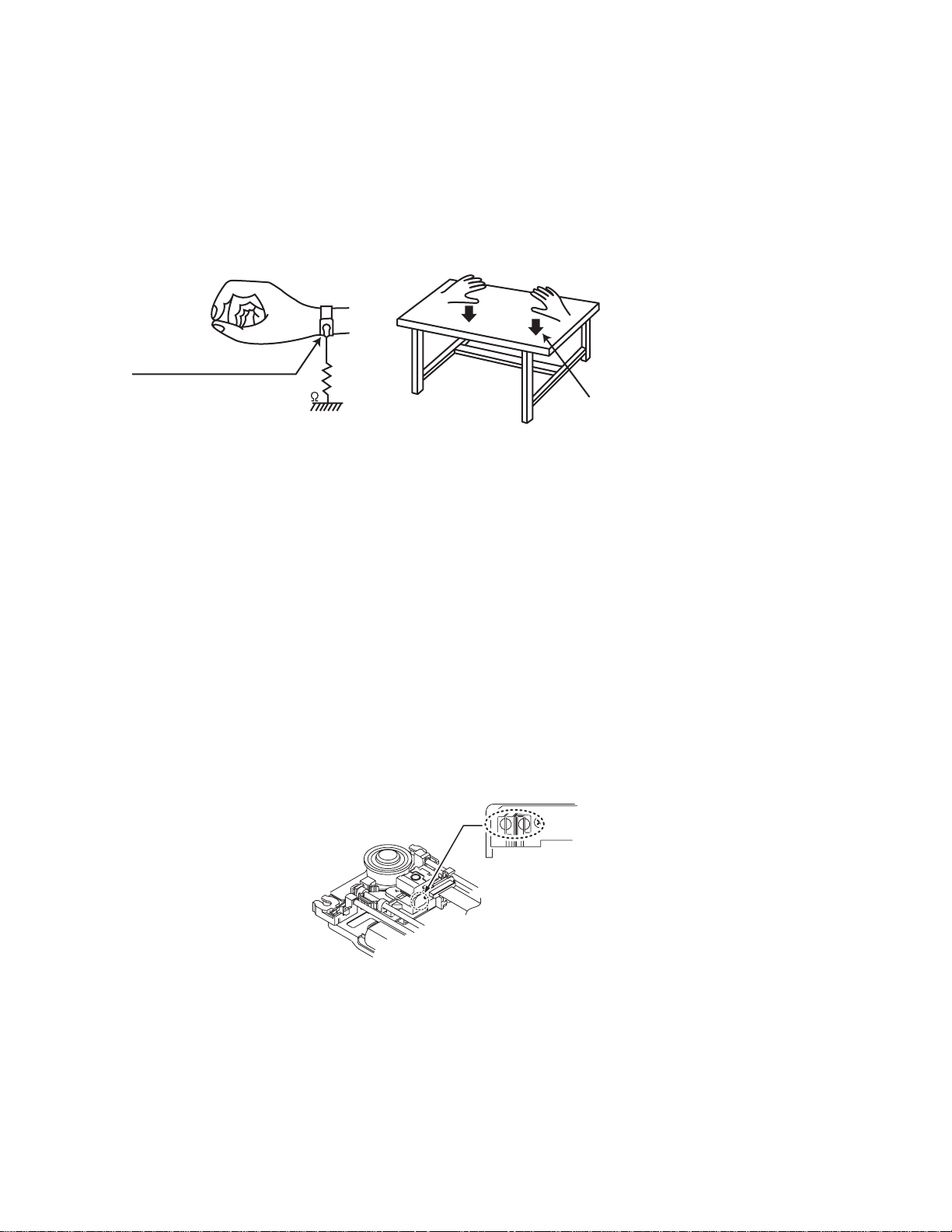
(1) Ground the workbench
Ground the workbench by laying conductive material (such as a conductive sheet) or an iron plate over it before placing the
traverse unit (optical pickup) on it.
(2) Ground yourself
Use an anti-static wrist strap to release any static electricity built up in your body.
(caption)
Anti-static wrist strap
1M
Conductive material
(conductive sheet) or iron plate
(3) Handling the optical pickup
• In order to maintain quality during transport and before installation, both sides of the laser diode on the replacement optical
pickup are shorted. After replacement, return the shorted parts to their original condition.
(Refer to the text.)
• Do not use a tester to ch eck the co ndition of th e laser dio de in the op tical pickup . The tester' s interna l power sourc e can easily
destroy the laser diode.
1.3 Handling the traverse unit (optical pickup)
(1) Do not subject the traverse unit (optical pickup) to strong shocks, as it is a sensitive, complex unit.
(2) Cut off the shorted part of the flexible cable using nip pers, etc. aft er replacing the optical pi ckup. For sp ecific det ails, refer to the
replacement procedu re i n the text. Remove the an ti-s tat ic pin w he n re pl aci ng the traverse unit. Be c are ful not to take too long a
time when attaching it to the connector.
(3) Handle the flexible cable carefully as it may break when subjected to strong force.
(4) It is not possible to adjust the semi-fixed resistor that adjusts the laser power. Do not turn it.
1.4 Attention when traverse unit is decomposed *Please refer to "Disassembly method" in the text for the pickup unit.
• Apply solder to the short land before the card wire is disconnected from the connector on the pickup unit.
(If the card wire is disconnected without applying solder, the pickup may be destroyed by static electricity.)
• In the assembly, be sure to remove solder from the short land after connecting the card wire.
Solder short land section
1-4 (No.MB658<Rev.001>)
Page 5

1.5 Important for laser products
1.CLASS 1 LASER PRODUCT
2.CAUTION :
(For U.S.A.) Visible and/or invisible class II laser radiation
when open. Do not stare into beam.
(Others) Visible and/or invisible class 1M laser radiation
when open. Do not view directly with optical instruments.
3.CAUTION : Visible and/or invisible laser radiation when
open and inter lock failed or defeated. Avoid direct
exposure to beam.
4.CAUTION : This laser product uses visible and/or invisible
laser radiation and is equipped with safety switches which
prevent emission of radiation when the drawer is open and
the safety interlocks have failed or are defeated. It is
dangerous to defeat the safety switches.
5.CAUTION : If safety switches malfunction, the laser is able
to function.
6.CAUTION : Use of controls, adjustments or performance of
procedures other than those specified here in may result in
hazardous radiation exposure.
!
Please use enough caution not to
see the beam directly or touch it
in case of an adjustment or operation
check.
REPRODUCTION AND POSITION OF LABELS and PRINT
WARNING LABEL and PRINT
(No.MB658<Rev.001>)1-5
Page 6

SECTION 2
SPECIFIC SERVICE INSTRUCTIONS
This service manual does not describe SPECIFIC SERVICE INSTRUCTIONS.
SECTION 3
DISASSEMBLY
3.1 Main body
3.1.1 Removing the Top cover (See Fig 1, 2)
(1) Remove the four screws A attaching the Top cover. (See
Fig.1)
(2) Takeout two washers B and two washers C on the Top cov-
er. (See Fig.2)
A
A
Fig.1
C
B
Fig.2
1-6 (No.MB658<Rev.001>)
Page 7
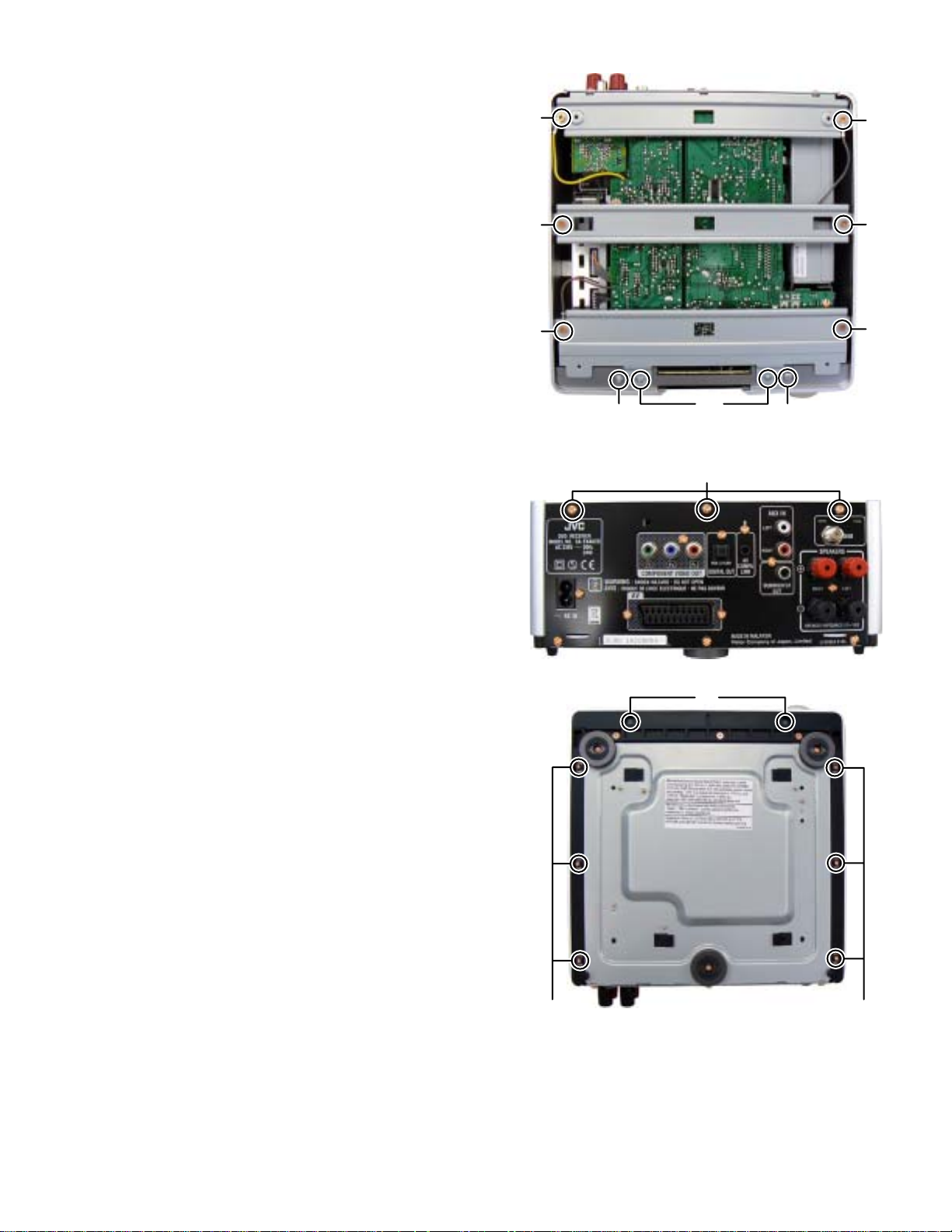
3.1.2 Removing the AL panel L and AL panel R (See Fig.3
to 5)
(1) Remove the two screws D and two screws E attaching the
Bridge A. (See Fig.3)
(2) Remove the two screws F attaching th e Bridge B. (See
Fig.3)
(3) Remove the two screws G and three screws H attaching
the bridge C. (See Fig.3, 4)
(4) Remove the two screws J attaching the AL panel L a nd AL
panel R. (See Fig.3)
(5) Remove the two screws K and six screws L attaching the
AL panel L and AL panel R. (See Fig.5)
G
F
G
F
E
E
D
JJ
Fig.3
H
Fig.4
K
LL
Fig.5
(No.MB658<Rev.001>)1-7
Page 8
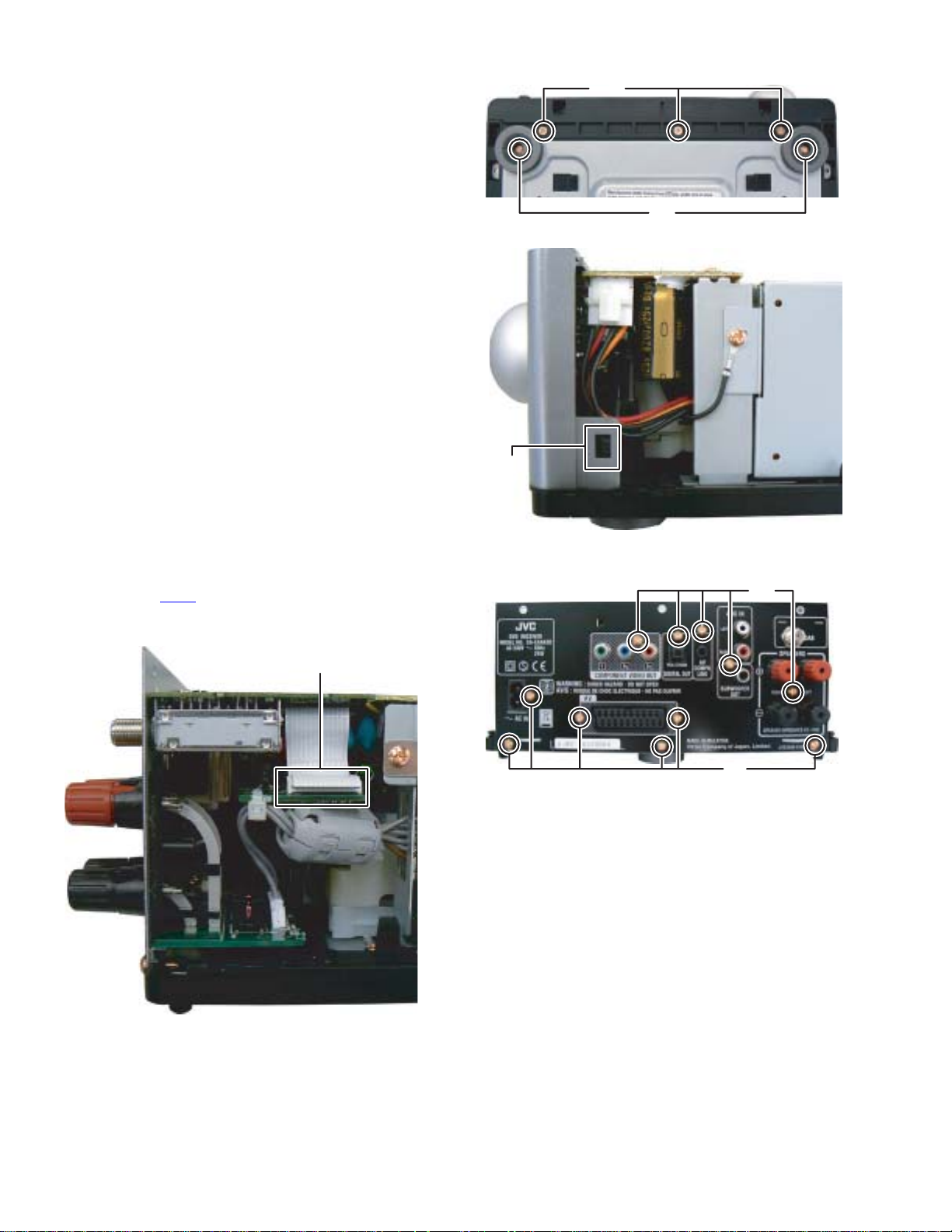
3.1.3 Removing the Front panel (See Fig.6, 7)
(1) Remove the two screws M attaching the Foot. (See Fig.6)
(2) Remove the three screws N attaching the Foot. (See Fig.6)
(3) Disengage two hooks a engaged both side of the Front
panel. (See Fig.7)
N
M
Fig.6
hook a
3.1.4 Removing the Rear panel (with DAB tuner pack) (See Fig.8, 9)
(1) Disconnect the card wire from DAB tuner pack connected
to connector CN21
(2) Remove the eleven screws P attaching the Rear panel.
(See Fig.9)
of the Micon board. (See Fig,8)
CN21
Fig.7
P
P
Fig.9
1-8 (No.MB658<Rev.001>)
Fig.8
Page 9

3.1.5 Removing the Switching power supply unit (see Fig.10)
(1) Disconnect the connector wire from Switching power sup-
ply unit connected to connector CN201
(2) Remove the one screw Q attaching t he Switching pow er
supply unit.
3.1.6 Removing the Headphone board (See Fig.11)
(1) Disconnect the connector wire from Main bo ard conn ected
to connector CN443
(2) Disconnect the earth wire from Bottom chassis connected
to post pin TP401 of the Headphone board.
(3) Remove the one screw R attaching the Hea dphone board.
of the Headphone board.
of the Main board.
Q
CN201
Fig.10
R
CN443
Fig.11
TP401
(No.MB658<Rev.001>)1-9
Page 10

3.1.7 Removing the Main board (See Fig.12 to 14)
(1) Disconnect the card wire from Micon board connected to
connector CN202
(2) Disconnect the card wire from DVD m echan ism c onnec ted
to connector CN206
(3) Disconnect the connector wires from Main board connect-
ed to connector CN102 and CN103 of the Digital amp
board. (See Fig.12)
(4) Remove the three screws S attaching the Main board. (See
Fig.12)
(5) Disconnect the connector wires from Main board connect-
ed to connector CN713
(See Fig.13)
(6) Disconnect the Earth wire from bottom chassis connected
to test point TP201
Fig.14)
of the Main board. (See Fig.12)
of the Main board. (See Fig.12)
and CN714 of the Micon board.
and TP204 of the Main board. (See
CN714
SS
CN202
CN102
CN103
S
CN206
Fig.12
CN713
Fig.13
TP201
1-10 (No.MB658<Rev.001>)
TP204
Fig.14
Page 11

3.1.8 Removing the Micon board (See Fig.15)
(1) Disconnect the connector wire from Micon board connect-
ed to connector CN101
(2) Disconnect the card wire from SCART board connected to
connector CN711
(3) Disconnect the card wire from Loader board connected to
connector CN701 of the Micon board.
(4) Disconnect the card wire from Front end board connected
to connector CN708
(5) Remove the two screws T attaching the Micon board.
of the Digital amp board.
of the Micon board.
of the Micon board.
CN701
TT
3.1.9 Removing the Digital amp board (See Fig.16)
(1) Disconnect the connector wire from Di gital amp board con-
nected to connector CN301
(2) Remove the one screw U attaching the Digital amp board.
of the Speaker terminal bo ard.
CN711
CN708 CN101
Fig.15
U
CN301
Fig.16
(No.MB658<Rev.001>)1-11
Page 12

3.1.10 Removing the DVD mechanism (See Fig.17)
(1) Remove the three screws V attaching the DVD mecha-
nism.
3.1.11 Removing the SCART board (See Fig.18)
(1) Remove the one screw W attaching the SCART board.
VV
V
Fig.17
3.1.12 Removing the Speaker terminal board (See Fig.18)
Remove the one screw X attaching the Speaker terminal board.
3.1.13 Removing the Front board (See Fig.19)
(1) Remove the volume knob.
(2) Remove the nine screws Y attaching the Front board.
1-12 (No.MB658<Rev.001>)
WX
Fig.18
Y
Y
Fig.19
Page 13

3.2 DVD mechanism
3.2.1 Removing the traverse mechanism
(See Fig.1 to 6)
(1) Remove the two screws A attaching the tr amecha ho lder
from top side of DVD mechanism assembly. (See Fig.1)
(2) Remove the two screws B attaching the DVD module
board. (See Fig.2)
(3) Remove the four screws C attaching the CB holder and
take out it. (See Fig.3)
(4) Remove the four screws D attaching the traverse mecha-
nism. (See Fig.4)
(5) Solder the solder part of DVD pick up. (See Fig.5)
(6) Disconnect the card wire from CN101
DVD module board. (See Fig. 6)
Caution:
• Solder the short land section on the DVD pickup before dis-
connecting the card wire from the connector on the DVD
pickup. If the card wire i s disconnected w ithout attaching solders, the pickup may be destroyed by static electricity.
• When attaching the DVD pickup, be sure to remove solders
from the short land section after connecting the card wire to
the connector on the DVD pickup.
and CN201 on the
A
Clamper base
B
A
DVD mechanism assembly
Fig.1
DVD mechanism assembly
B
DVD module board
Fig.2
(No.MB658<Rev.001>)1-13
Page 14

DVD module board
DVD module board
CN101
CN201
C
C
CC
Fig.3
DVD mechanism assembly
Traverse mechanism assembly
Fig.6
DD
Fig.4
Solder short land section
Fig.5
1-14 (No.MB658<Rev.001>)
Page 15

3.2.2 Removing the pickup assembly
(See Fig.7 to 11)
(1) Remove the two rod springs pressing the guide s haft. (See
Fig.7)
(2) Remove the screw E and F attaching the spring holde r.
(See Fig.8)
(3) Remove the read screw from traverse mechanism assem-
bly. (See Fig.9)
Caution:
When remove the lead screw, do not loss the middle
gear. (See Fig.10 and 11)
(4) Remove the bar spring pressing the shaft. (See Fig.10)
(5) Take out the pickup assembly from traverse mechanism
chassis by order. (See Fig.11)
(SHAFT)
(T.TABLE)
HOOK
(BAR SPRING)
Fig.10
ROD SPRING ROD SPRING
Fig.7
Spring holder
Fig.8
order 2
order 3
order 1
Fig.11
EF
Middle gear
Lead screw
Fig.9
(No.MB658<Rev.001>)1-15
Page 16

3.2.3 Removing the feed motor assembly
(See Fig.12)
(1) Remove the one screw G attaching the feed motor assem -
bly.
(2) Remove the feed motor wires from solder part of spindle
motor board.
Solder part
3.2.4 Removing the spindle motor assembly
(See Fig.13)
(1) Remove the three screws H attaching the spindle motor
from spindle motor board.
Middle gear
Lead screw
Fig.12
H
Spindle motor
Fig.13
G
1-16 (No.MB658<Rev.001>)
Page 17

3.2.5 Removin g the tray assembly
(See Fig.14 & 15)
(1) Remove the two screws J attaching the clamper base.
(See Fig.14)
(2) Remove the one screw K attaching the shaft guide from
bottom side. (See Fig.14)
(3) Remove the two screws L attaching the shaft guide from
top side. (See Fig.15)
Caution:
When attach the tray assem bly, boss of lo ading su b asse mbly
should atta ch to guide of bottom si de at tray as sembly. (Se e
Fig.15)
J
order 1
order 2
clamper base
L
K
Fig.15
[bottom side]
Fig.14
(No.MB658<Rev.001>)1-17
Page 18

SECTION 4
ADJUSTMENT
4.1 ATTENTION IN SERVICE OF DVD SECTION
(1) When pickup, Flash ROM ,DVD module board were changed, initialize EEPROM by all means.
(2) When full initialization was execu ted, execute learning w ith a DVD test disc by all means.
Test disc : VT-501, VT-502
Learning m ethod : It is adjusted automatically by normal playback of a DVD disc.
4.2 DVD TEST MODE
4.2.1 Content of correspondence TEST MODE
(1) Version, Region, Learning status check mode
(2) NORMAL initialize, FULL initialize
(3) Device key checksum indication mode
(4) Micon version indication mode
(5) FL all on mode
(6) FRONT END check mode
4.2.2 Mode transition
TEST MODE into the press [PLAY] key and [STOP] key together of main body, connect the AC power.
After into the TEST MODE, mode select by [MENU] key.
PLAY+STOP+AC
Version, Region, Learning
status indication mode
[>>|] key(*1) [|<<] key(*1)
NORMAL
initialize
[STOP] key 4sec
long press(*1)
FULL
initialize
MENU key
Device key
write
MENU key
Device key
MENU key MENU key MENU key
Micon version
checksum
mode
indication mode
MENU key
FL all on
mode
FRONT END
check mode
(*1): Change form Version, Region, Learning status indication mode to NORMAL initialize, FULL initialize is effective only main body key.
The following keys are allocated when there are neither [>>|] key nor [|<<] key in the main body.
NORMAL initialize: PAUSE key
FULL initialize: STOP key 4sec long press
Device key write: PLAY key
When a basic key cannot be allocated by the set, it is assumed it is arbitrary.
4.2.3 Processing details
The communication of operated FL(LCD) display and DVD back end microcomputer is shown as follows.
*It is assumed to be OK to differ from the content of the specification because the number of digits is different according to the set for the FL(LCD) display.
*It is assumed to be OK to differ from the content of the specification because it also has the relation between arrangement and presence b y th e s et also fo r
the key.
STEP Operation Movement RemarksFL(LCD)indication
132
46578
132
1
AC is pulled out, and
double press [PLAY]
and [STOP] key of the
main body
Keep step 1, connect
2
AC
Version, Region, Learning
status indication mode
Power on by test mode,
version indication to FL
TEST
Version indication
JC#
The display to the version code is as
follows.
JC, 1U, D, E
2U, 3U, UB, UT
4U, UY, EE, UF
1-18 (No.MB658<Rev.001>)
Region indication (# part)
Learning and Initialization from the back
end is displayed in the second line( )
of the FL display.
Blank indication at 0xFF
Page 19

STEP Operation Movement RemarksFL(LCD)indication
Press a [>>|] key of the
main body.
NORMAL initialize
132
132
TEST
46578
JC#
Learning status (first digit)
BCA CHECK OK incomplete,
DVD learning incomplete,
CD learning incomplete (indication 7)
BCA CHECK OK incomplete,
DVD learning complete,
CD learning incomplete (indication 6)
BCA CHECK OK incomplete,
DVD learning incomplete,
CD learning complete (indication 5)
BCA CHECK OK incomplete,
DVD learning complete,
CD leaning complete (indication 4)
BCA CHECK OK complete,
DVD learning incomplete,
CD learning incomplete (indication 3)
BCA CHECK OK complete,
DVD learning complete,
CD learning incomplete (indication 2)
BCA CHECK OK complete,
DVD learning incomplete,
CD learning complete (indication 1)
BCA CHECK OK complete
DVD learning complete
CD learning complete (indication 0)
(BCA READ CHECK result is only BCA
READ OK, it to complete)
Initialization status (second digit)
FULL initialize complete (indication 3)
NORMAL initialize complete (indication 0)
Initialize incomplete (blank indication)
Continue pressing a
[STOP] key of the main
body.(4sec)
FULL initialize
3 Press a [MENU] key of
the remote controller.
4 Press a [MENU] key of
the remote controller.
Press a [ON SCREEN]
key of the remote
controller.
Press a [MENU] key of
5
the remote controller.
Press a [MENU] key of
6
the remote controller.
DEVICE CHECKSUM
indication mode
Indicate the CHECKSUM
of the Device key to FL
(4 byte)
Micon version indication
mode
Indicate the version of micon
to FL
Micon version indication
mode
Indicate the version of micon
to FL
FL all on mode
All FL and all LED to ON
FRONT END check mode
Indicate the front end check
mode to FL
SU
SC
BE
JC#TEST
The AVC protocol is returned from
M
high speed to normal speed.
(Return it to the normal mode when
coming off the TEST mode. )
Indicate CHECKSUM to FL
,,,
,,,
: Syscon Version
##
## : Syscon Romcorr Version
$$$$ : DVD Backend Version
$$$$
KCHEC
: CPPM
: CPRM
(No.MB658<Rev.001>)1-19
Page 20

STEP Operation Movement RemarksFL(LCD)indication
Press a [1] key of the
remote controller
Press a [2] key of the
remote controller
Disc startup and through
playback
(Playback starts from the
start position)
Presence of WOBBLE
0:WOBBLE_NO_CHECK
(un check)
1:WOBBLE_PRESS_MEDIA
(press)
2:WOBBLE_MINUS_MEDIA
(DVD-R/-RW media)
3:WOBBLE_PLUS_MEDIA
(DVD+R/+RW media)
132
132
WO B
46578
KCHEC
Upper : 0
Lower : WOBBLE detection result
Press a [3] key of the
remote controller
Press a [4] key of the
remote controller
Press a [5] key of the
remote controller
Press a [6] key of the
remote controller
Press a [8] key of the
remote controller
Press a [9] key of the
remote controller
Port check mode
(TRACK,INDEX,DEMP,COPY)
1:INDEX Port = High
2:TRACK Port = High
3:COPY Port = High
4:DEMP Port = High
CD_LD lights and laser
current is displayed
DVD_LD lights and laser
current is displayed
DVD_SL x1 jitter
measurement mode
Content of BACKUP
memory(0x00-0x63)
indication (FWD)
Temperature sensor
(AD value) indication
POT
CLD
DLD
JIT
BUP
TMP
Upper : 0x01-0x04 (check port number)
Lower : 0
Upper : Laser current value
(BACKUP value,Real measured value)
Lower : 0
Upper : Laser current value
(BACKUP value,Real measured value)
Lower : 0
Upper : Laser current value
(BACKUP value,Real measured value)
Lower : Real measured value
Upper Byte1 : Display option
0x00 : BACKUP area
0xFF : permanent area
Upper Byte2 : BACKUP memory address
(0x00-0x63)
Lower : Content of BACKUP memory
Upper : 0
Lower : Temperature sensor value
Press a [10] key of the
remote controller
Press a [0] key of the
remote controller
Press a [ 10] key of the
remote controller
>
=
1-20 (No.MB658<Rev.001>)
DVD-DL(parallel,opposite)
Search & jitter
measurement of the
specified position of
DVD-SL
MONITOR output switch
1: SRV_MONI_CIRC
2: SRV_MONI_SERVO
3-5: SRV_MONI_ANALOG
6-7: SRV_MONI_DRC
8-11: SRV_MONI_SERVO
_JIG
12: SRV_MONI_DEFAULT
BCA READ CHECK
0:During BCA READ
1:BCA READ OK
2:BCA SEEK ERROR
3:BCA READ ERROR
4:SPINUP adjust ERROR
-
DL
MOT
BCA
Upper : 0x00-0x06(measure at VT501)
Lower : Jitter value
Upper : 0x00-0x0C
Lower : 0
Page 21

STEP Operation Movement RemarksFL(LCD)indication
Press a [STOP] key of
the main body or
remote controller
Press a [OPEN/CLOSE]
key of the main body or
remote controller
Disc stop, LD-OFF
Tray Open/Close
132
46578
132
CHECK
CHECK
Press a [PLAY] key of
the main body or
remote controller
Press a [MENU] key of
7
the remote controller
Press a [POWER] key
of the main body
*1 Mode toggle done by press [MENU] key.
*2 STEP3 are only for DVD-AUDIO or VR correspondence model.
Disc playback
Back to STEP 2
Release the TEST MODE
Upper:Laser current value
(BACKUP value, Real measured value)
Lower:Jitter value
ETSTJC#
Release at each step
(No.MB658<Rev.001>)1-21
Page 22

4.3 TEST MODE
4.3.1 Mode transition
It shall be in the mode in normal POWER ON and prepare five modes.
(1) The test mode which enters by the receive of remote controller cord [STOP] + [POWER] + [1].
* It invalidate the whole test mode anything other than test remote controller cord [STOP] + [POWER] + [1].
(2) The version confirmation mode which enters by the receive of remote controller cord [STOP] + [POWER] + [10].
* The whole version confirmation mode invalidates wireless remote controller cord
[STOP] + [POWER] + [1], [STOP] + [POWER] + [2] and [STOP] + [POWER] + [ 10].
(3) The model excellent + act confirmation mode which enters by the reception of wir eless remote controller cord [STOP] + [POWER] + [ 10].
* The whole model name + dest inatio n confirm ation mode inv alida tes remote c ontroll er cord [STOP] + [POWER ] + [1], [S TOP]
+ [POWER] + [2] and [STOP] + [POWER] + [10].
* Only for in confirmation mode 5 indication and source DAB, it is decided that [UPPER] is specialized in a service mode Lite indication change.
(4) The temperature indication mode which enters by the receive of remote controller cord [STOP] + [POWER] + [2].
* The whole temperature indication mode invalidates remote controller cord [STOP] + [POWER] + [1],
[STOP] + [POWER] + [10] and [STOP] + [POWER] + [ 10].
Normal mode
[STOP] + [POWER] + [1]
Test mode
"FL & LED all ON"
Any key in
Release the
"FL & LED all ON"
Continue the
Test mode (2)
[STOP] + [POWER] + [0]
[STOP] + [POWER] + [2]
[STOP] + [POWER] + [ 10]
[STOP] + [POWER] + [10]
UPPER (DISPLAY) Key
COLD
START
Temperature
indication mode
Model name
Destination
confirmation mode
[STOP] + [POWER] + [0]
[STOP] + [POWER] + [2]
+
Transientness
4 sec.
[STOP]
+
[POWER]
+
[10]
UPPER
(DISPLAY) Key
UPPER
(DISPLAY) Key
UPPER
[STOP] + [POWER] + [1] or HARD RESET
(DISPLAY) Key
[STOP] + [POWER] + [1] or HARD RESET
UPPER
(DISPLAY) Key
UPPER
(DISPLAY) Key
DAB Micon version
V019-FF
"Actual service ID"
SERVICE or Sid=
"Audio average error rate"
Audio Err
"FIC average error rate"
FIC Err
"Actual ensemble ID"
"gain mode, bandwidth
(RF setting value)"
UPPER (DISPLAY) Key
Eid
RF Set
"Tuner setting data"
Tun Set3
(DISPLAY) Key
"Tuner setting data"
Tun Set2
(DISPLAY) Key
"Tuner setting data"
Tun Set1
(DISPLAY) Key
"DAB now status"
NOW_SEQ
(DISPLAY) Key
"AUTMOD value,
DETMOD value,
MOD value"
DAB MODE
[STOP]
+
[POWER]
+
[10]
UPPER
UPPER
UPPER
UPPER
Version confirmation mode 1
"Syscon & ROMCOLLE version"
[STOP] + [POWER] + [10]
Version confirmation mode 2
"Back end version"
[STOP] + [POWER] + [10]
Version confirmation mode 3
"DVD unit destination +
REGION CODE"
[STOP] + [POWER] + [10]
Version confirmation mode 4
"DVD module information"
[STOP] + [POWER] + [10]
Version confirmation mode 5
"DAB module version"
[STOP] + [POWER] + [10]
1-22 (No.MB658<Rev.001>)
UPPER (DISPLAY) Key
Normal mode (Release the TEST MODE)
Page 23

4.3.2 Set to DAB Test mode
(1) Source to DAB.
(2) Press [STOP] + [POWER] + [10] key together.
(3) Press [STOP] + [10], keep this state version indication is replaced whenever press [POWER] key.
Mode change to version confirmation mode 5 "DAB module versio n", press [UPP ER] key of remote controller to shift the DAB test mode.
SECTION 5
TROUBLESHOOTING
This service manual does not describe TROUBLESHOOTING.
(No.MB658<Rev.001>)1-23
Page 24

Victor Company of Japan, Limited
Audio/Video Systems category 10-1,1chome,Ohwatari-machi,Maebashi-city,371-8543,Japan
(No.MB658<Rev.001>)
Printed in Japan
VPT
 Loading...