

Page 1
SERVICE MANUAL
COMPACT COMPONENT SYSTEM
MB34820052
EX-A1,EX-P1,EX-A5
EX-A1
Area suffix
US ------------------------ Singapore
UB ---------------------- Hong Kong
UF ------------------------------ China
UP ----------------------------- Korea
UT ---------------------------- Taiwan
UW ----------- Brazil,Mexico,Peru
(SP-EXA1)
(SP-EXP1)
(CA-EXA1)
(CA-EXP1)
(SP-EXA1)
(SP-EXP1)
UJ ---------------------- U.S.Military
EX-P1
Area suffix
UF ------------------------------ China
UP ----------------------------- Korea
UT ---------------------------- Taiwan
UJ ---------------------- U.S.Military
EX-A5
(CA-EXA5) (SP-EXA5)(SP-EXA5)
EX-A1
Speaker 1-way bass-reflex type
8cm wood cone x1
EX-P1 EX-A5
1-way bass-reflex type
8cm wood cone x1
UT ---------------------------- Taiwan
2-way bass-reflex type
11cm wood cone x1
2cm wood cone x1
Area suffix
TABLE OF CONTENTS
1 PRECAUTION. . . . . . . . . . . . . . . . . . . . . . . . . . . . . . . . . . . . . . . . . . . . . . . . . . . . . . . . . . . . . . . . . . . . . . . . . 1-3
2 SPECIFIC SERVICE INSTRUCTIONS . . . . . . . . . . . . . . . . . . . . . . . . . . . . . . . . . . . . . . . . . . . . . . . . . . . . . . 1-6
3 DISASSEMBLY . . . . . . . . . . . . . . . . . . . . . . . . . . . . . . . . . . . . . . . . . . . . . . . . . . . . . . . . . . . . . . . . . . . . . . . 1-7
4 ADJUSTMENT . . . . . . . . . . . . . . . . . . . . . . . . . . . . . . . . . . . . . . . . . . . . . . . . . . . . . . . . . . . . . . . . . . . . . . . 1-24
5 TROUBLESHOOTING . . . . . . . . . . . . . . . . . . . . . . . . . . . . . . . . . . . . . . . . . . . . . . . . . . . . . . . . . . . . . . . . . 1-28
COPYRIGHT © 2005 Victor Company of Japan, Limited
No.MB348
2005/2
Page 2
SPECIFICATION
COMPACT COMPONENT SYSTEM (EX-A1,EX-P1,EX-A5)
General Power source AC 110 - 240 V , 50 Hz/60 Hz (EX-A1, EX-P1)
AC 110 V for Taiwan (EX-A5)
Power consumption 24 W (in operation)
1.1 W (on standby)
Weight 3.0 kg
External dimensions (W × H × D) 232 mm × 100 mm × 269 mm
DVD player Playable discs DVD VIDEO, DVD AUDIO, VCD, Super VCD, CD,
CD-R/RW (CD, VCD, MP3, JPEG format), DVD-R/RW (video format)
Video output Color system NTSC(EX-A1, EX-P1)
NTSC/PAL selectable (EX-A5)
Horizontal resolution 500 lines
Composite × 1 1.0 V (p-p)/75 Ω, synchronization negative
S-video × 1 Y output: 1.0 V (p-p)/75 Ω, synchronization negative
C output: 0.286 V (p-p)/75 Ω
Component × 1 Y output: 1.0 V (p-p)/75 Ω
PB/PR output: 0.7 V (p-p)/75 Ω
Audio output Analog sound output Speakers × 2 60 W (30 W + 30 W) at 4 Ω (10% THD)
Output power (IEC 268-3) Fitting impedance: 4 Ω to 16 Ω
Headphones × 1 11 mW/32 Ω
Fitting impedance 16 Ω to 1 kΩ
Subwoofer × 1 500 mVrms/10 kΩ
Digital sound output Optical × 1 -21 dBm to -15 dBm
Other output AV COMPU LINK × 2 (Ø3.5)
Audio input Sound input AUX × 1
Level 1 250 mV/50 kΩ
Level 2 500 mV/50 kΩ
Tuner FM tuner Receiving frequency 87.50 MHz to 108.00 MHz
Antenna 75Ω- unbalanced type
AM tuner Receiving frequency 531 kHz to 1710 kHz (at 9 kHz interval space)
530 kHz to 1710 kHz (at 10 kHz interval space)
Antenna External antenna jack (loop antenna)
SPEAKER (SP-EXA1/SP-EXP1)
Type 1-way bass-reflex type Magnetically shielded type
Speaker 8cm cone × 1
Power handling capacity 30 W
Impedance 4Ω
Sound pressure level 81 dB/W m (SP-EXA1)
82 dB/W m (SP-EXP1)
Dimension (W × H × D) 120 mm × 161 mm × 239 mm
Weight (1 unit) 1.6 kg (SP-EXA1)
1.9 kg (SP-EXP1)
SPEAKER (SP-EXA5)
Type 2-way bass-reflex type Magnetically shielded type
Speaker Woofer : 10.5 cm wood cone
Tweeter : 2 cm wood cone
Power handling capacity 100 W
Impedance 4Ω
Crossover frequency 3.5 kHz
Sound pressure level 80.5 dB/W m
Dimension (W × H × D) 143 mm × 257 mm × 243 mm
Weight (1 unit) 3.5 kg
Designs and Specifications are subject to change without notice.
1-2 (No.MB348)
Page 3
SECTION 1
PRECAUTION
1.1 Safety Precautions
(1) This design of this product contains special hardware and
many circuits and components specially for safety purposes. For continued protection, no changes should be made
to the original design unless authorized in writing by the
manufacturer. Replacement parts must be identical to
those used in the original circuits. Services should be performed by qualified personnel only.
(2) Alterations of the design or circuitry of the product should
not be made. Any design alterations of the product should
not be made. Any design alterations or additions will void
the manufacturers warranty and will further relieve the
manufacture of responsibility for personal injury or property
damage resulting therefrom.
(3) Many electrical and mechanical parts in the products have
special safety-related characteristics. These characteristics are often not evident from visual inspection nor can the
protection afforded by them necessarily be obtained by using replacement components rated for higher voltage, wattage, etc. Replacement parts which have these special
safety characteristics are identified in the Parts List of Service Manual. Electrical components having such features
are identified by shading on the schematics and by ( ) on
the Parts List in the Service Manual. The use of a substitute
replacement which does not have the same safety characteristics as the recommended replacement parts shown in
the Parts List of Service Manual may create shock, fire, or
other hazards.
(4) The leads in the products are routed and dressed with ties,
clamps, tubings, barriers and the like to be separated from
live parts, high temperature parts, moving parts and/or
sharp edges for the prevention of electric shock and fire
hazard. When service is required, the original lead routing
and dress should be observed, and it should be confirmed
that they have been returned to normal, after reassembling.
(5) Leakage shock hazard testing
After reassembling the product, always perform an isolation check on the exposed metal parts of the product (antenna terminals, knobs, metal cabinet, screw heads,
headphone jack, control shafts, etc.) to be sure the product
is safe to operate without danger of electrical shock.Do not
use a line isolation transformer during this check.
• Plug the AC line cord directly into the AC outlet. Using a
"Leakage Current Tester", measure the leakage current
from each exposed metal parts of the cabinet, particularly any exposed metal part having a return path to the
chassis, to a known good earth ground. Any leakage current must not exceed 0.5mA AC (r.m.s.).
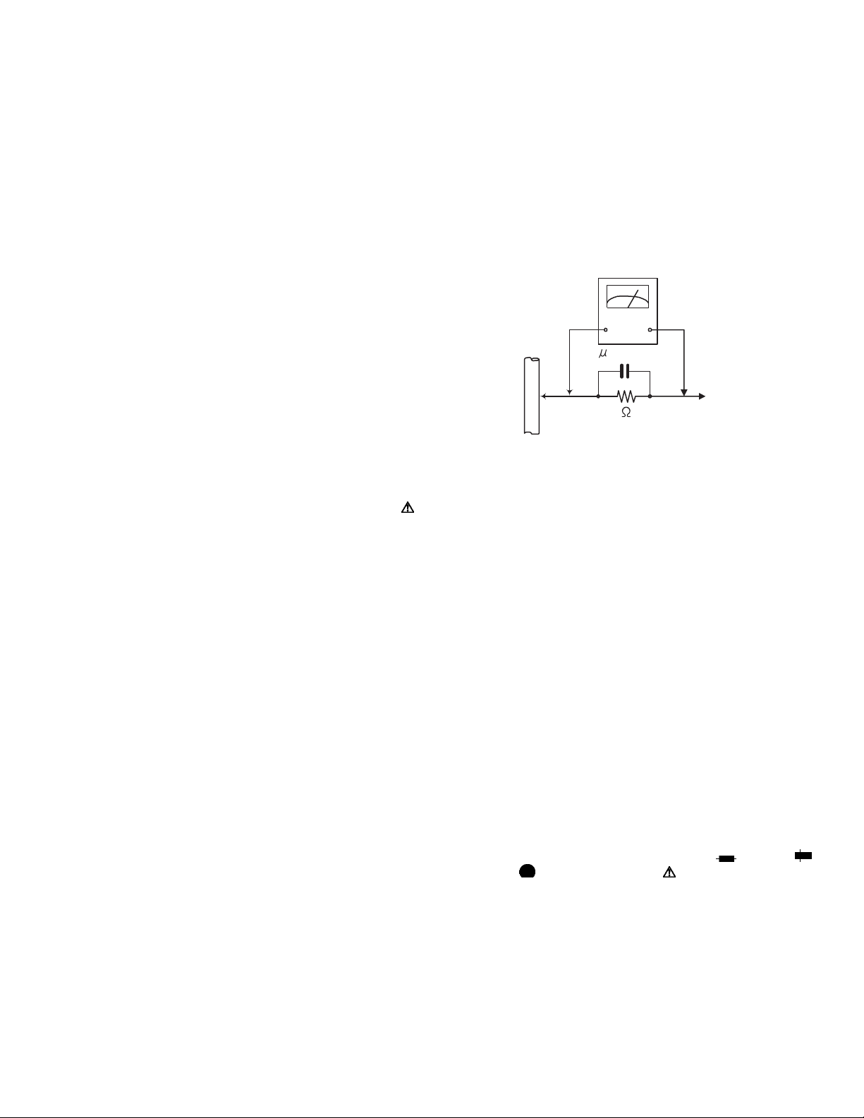
• Alternate check method
Plug the AC line cord directly into the AC outlet. Use an
AC voltmeter having, 1,000Ω per volt or more sensitivity
in the following manner. Connect a 1,500Ω 10W resistor
paralleled by a 0.15µF AC-type capacitor between an ex-
posed metal part and a known good earth ground.
Measure the AC voltage across the resistor with the AC
voltmeter.
Move the resistor connection to each exposed metal
part, particularly any exposed metal part having a return
path to the chassis, and measure the AC voltage across
the resistor. Now, reverse the plug in the AC outlet and
repeat each measurement. Voltage measured any must
not exceed 0.75 V AC (r.m.s.). This corresponds to 0.5
mA AC (r.m.s.).
AC VOLTMETER
(Having 1000
ohms/volts,
or more sensitivity)
0.15 F AC TYPE
Place this
probe on
1500 10W
Good earth ground
1.2 Warning
(1) This equipment has been designed and manufactured to
meet international safety standards.
(2) It is the legal responsibility of the repairer to ensure that
these safety standards are maintained.
(3) Repairs must be made in accordance with the relevant
safety standards.
(4) It is essential that safety critical components are replaced
by approved parts.
(5) If mains voltage selector is provided, check setting for local
voltage.
1.3 Caution
Burrs formed during molding may be left over on some parts
of the chassis.
Therefore, pay attention to such burrs in the case of preforming repair of this system.
1.4 Critical parts for safety
In regard with component parts appearing on the silk-screen
printed side (parts side) of the PWB diagrams, the parts that are
printed over with black such as the resistor ( ), diode ( )
and ICP ( ) or identified by the " " mark nearby are critical
for safety. When replacing them, be sure to use the parts of the
same type and rating as specified by the manufacturer.
(This regulation dose not Except the J and C version)
each exposed
metal part.
(No.MB348)1-3
Page 4
1.5 Preventing static electricity
Electrostatic discharge (ESD), which occurs when static electricity stored in the body, fabric, etc. is discharged, can destroy the laser
diode in the traverse unit (optical pickup). Take care to prevent this when performing repairs.
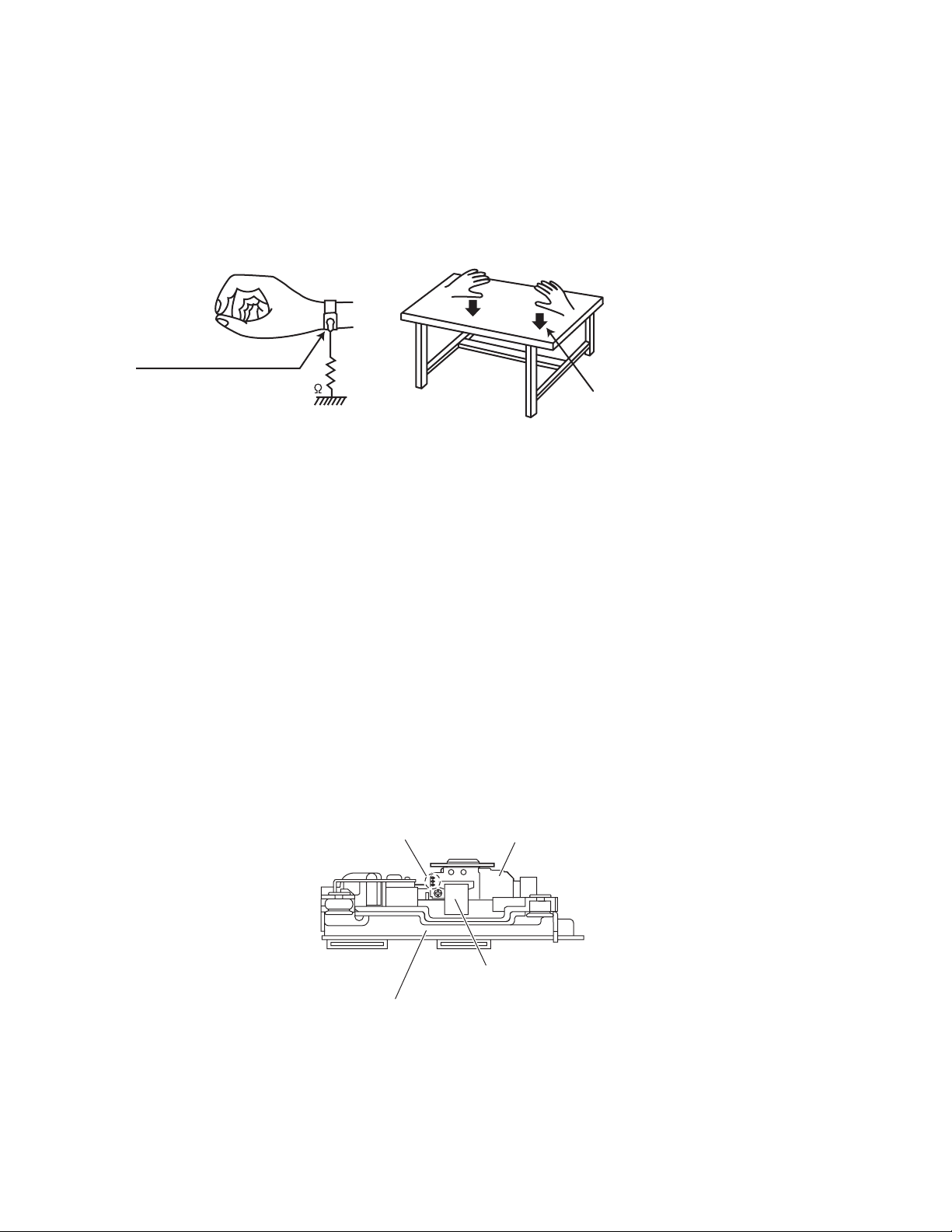
1.5.1 Grounding to prevent damage by static electricity
Static electricity in the work area can destroy the optical pickup (laser diode) in devices such as laser products.
Be careful to use proper grounding in the area where repairs are being performed.
(1) Ground the workbench
Ground the workbench by laying conductive material (such as a conductive sheet) or an iron plate over it before placing the
traverse unit (optical pickup) on it.
(2) Ground yourself
Use an anti-static wrist strap to release any static electricity built up in your body.
(caption)
Anti-static wrist strap
1M
Conductive material
(conductive sheet) or iron palate
(3) Handling the optical pickup
• In order to maintain quality during transport and before installation, both sides of the laser diode on the replacement optical
pickup are shorted. After replacement, return the shorted parts to their original condition.
(Refer to the text.)
• Do not use a tester to check the condition of the laser diode in the optical pickup. The tester's internal power source can easily
destroy the laser diode.
1.6 Handling the traverse unit (optical pickup)
(1) Do not subject the traverse unit (optical pickup) to strong shocks, as it is a sensitive, complex unit.
(2) Cut off the shorted part of the flexible cable using nippers, etc. after replacing the optical pickup. For specific details, refer to the
replacement procedure in the text. Remove the anti-static pin when replacing the traverse unit. Be careful not to take too long a
time when attaching it to the connector.
(3) Handle the flexible cable carefully as it may break when subjected to strong force.
(4) I t is not possible to adjust the semi-fixed resistor that adjusts the laser power. Do not turn it.
1.7 Attention when traverse unit is decomposed
*Please refer to "Disassembly method" in the text for the pickup unit.
• Apply solder to the short land sections before the flexible wire is disconnected from the connecto on the servo board. (If the flexible
wire is disconnected without applying solder, the pickup may be destroyed by static electricity.)
• In the assembly, be sure to remove solder from the short land sections after connecting the flexible wire.
Short land section
pickup
1-4 (No.MB348)
Card wire
Traverse mechanism assembly
Page 5
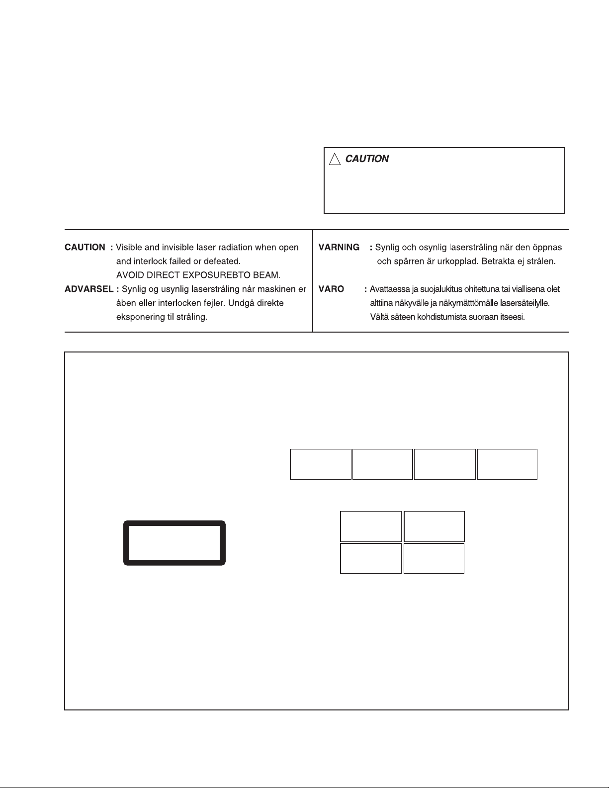
1.8 Important for laser products
!
1.CLASS 1 LASER PRODUCT
2.DANGER : Invisible laser radiation when open and inter
lock failed or defeated. Avoid direct exposure to beam.
3.CAUTION : There are no serviceable parts inside the
Laser Unit. Do not disassemble the Laser Unit. Replace
the complete Laser Unit if it malfunctions.
4.CAUTION : The CD,MD and DVD player uses invisible
laser radiation and is equipped with safety switches which
prevent emission of radiation when the drawer is open and
the safety interlocks have failed or are defeated. It is
dangerous to defeat the safety switches.
5.CAUTION : If safety switches malfunction, the laser is able
to function.
6.CAUTION : Use of controls, adjustments or performance of
procedures other than those specified here in may result in
hazardous radiation exposure.
Please use enough caution not to
see the beam directly or touch it
in case of an adjustment or operation
check.
REPRODUCTION AND POSITION OF LABELS
WARNING LABEL
CAUTION : Visible and Invisible
laser radiation when open and
interlock failed or defeated.
AVOID DIRECT EXPOSURE TO
BEAM. (e)
CLASS 1
LASER PRODUCT
ADVARSEL : Synlig og usynlig
laserstråling når maskinen er
åben eller interlocken fejeler.
Undgå direkte eksponering til
stråling. (d)
CAUTION : Visible and Invisible
laser radiation when open and
interlock failed or defeated.
AVOID DIRECT EXPOSURE TO
BEAM. (e)
VARNING : Synlig och
osynling laserstrålning när
den öppnas och spärren är
urkopplad. Betrakta ej
strålen. (s)
VARNING : Synlig och
osynling laserstrålning när
den öppnas och spärren är
urkopplad. Betrakta ej
strålen. (s)
VARO : Avattaessa ja suojalukitus
ohitettuna tai viallisena olet alttiina
näkyvälle ja näkymättömälle
lasersäteilylle. Vältä säteen
kohdistumista suoraan itseesi. (f)
ADVARSEL : Synlig og usynlig
laserstråling når maskinen er
åben eller interlocken fejeler.
Undgå direkte eksponering til
stråling. (d)
VARO : Avattaessa ja suojalukitus
ohitettuna tai viallisena olet alttiina
näkyvälle ja näkymättömälle
lasersäteilylle. Vältä säteen
kohdistumista suoraan itseesi. (f)
(No.MB348)1-5
Page 6

SECTION 2
SPECIFIC SERVICE INSTRUCTIONS
This service manual does not describe SPECIFIC SERVICE INSTRUCTIONS.
1-6 (No.MB348)
Page 7
SECTION 3
DISASSEMBLY
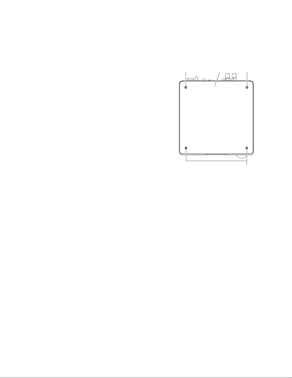
3.1 Main body section
3.1.1 Removing the top cover
(See Fig.1)
(1) From the top side of the main body, remove the four screws
A attaching the top cover.
A A
Top cover
Fig.1
A
(No.MB348)1-7
Page 8
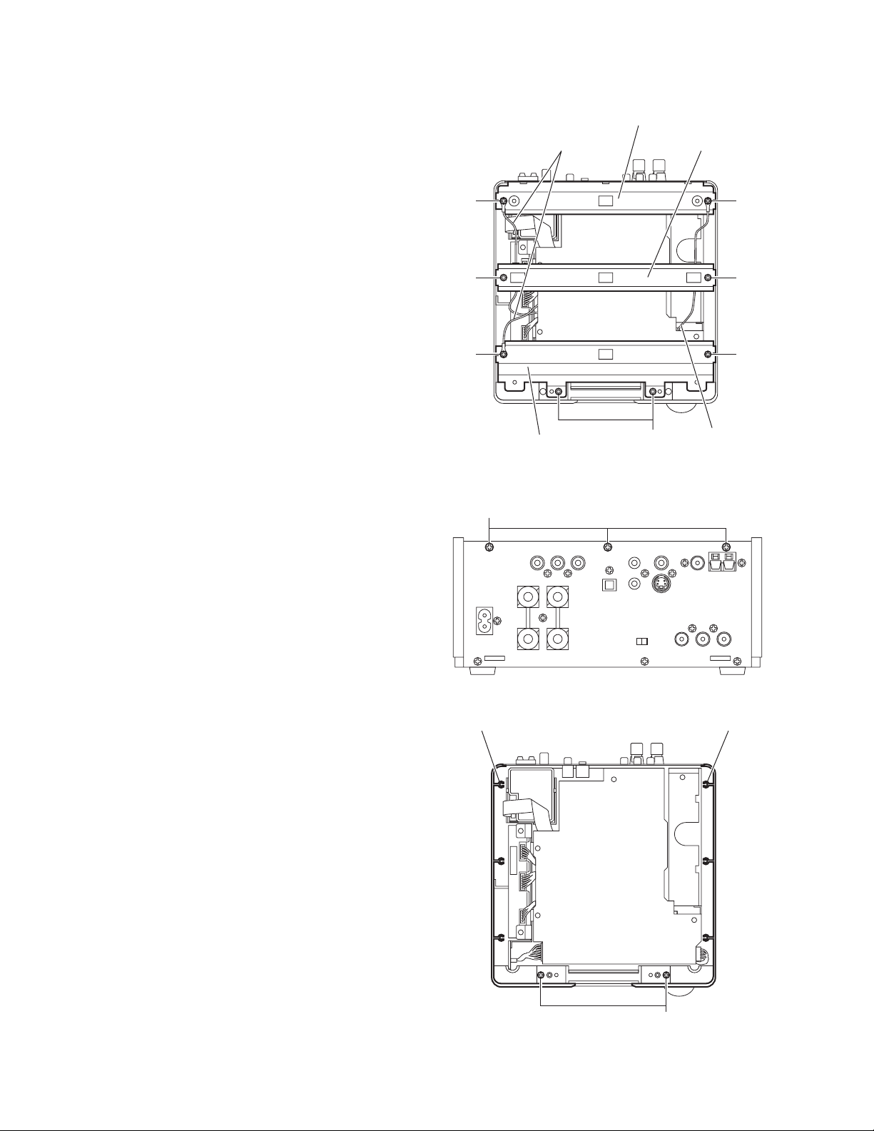
3.1.2 Removing the AL panel L and AL panel R (
A
See Figs.2 to 7.)
• Remove the top cover.
(1) Remove the two screws B, screw C and screw C' attaching
the bridge A. (See Fig.2.)
Reference:
When attaching the screw C' attach the lug wire with it.
(See Fig.2.)
(2) Remove the two screws C attaching the bridge B. (See
Fig.2.)
(3) Remove the two screws C' attaching the bridge C. (See
Fig.2.)
(4) From the back side of the main body, remove the three
screws D attaching the bridge C. (See Fig.3.)
Reference:
When attaching the screws C' attach the lug wires with
it. (See Fig.2.)
(5) From the top side of the main body, remove the two screws
E attaching the AL panel L and AL panel R. (See Fig.4.)
(6) From the bottom side of the main body, remove the three
screws F attaching the wood bar. (See Fig.5.)
(7) Remove the six screws G and two screws H attaching the
AL panel L and AL panel R. (See Fig.6.)
(8) Remove the AL panel L and AL panel R in the direction of
the arrow 2 while extending the back section of the AL panel L and AL panel R in the direction of the arrow 1. (See
Fig.7.)
C'
C
C'
D
Lug wires
Fig.2
Bridge C
BBridge A
Bridge B
C'
C
C
Lug wire
1-8 (No.MB348)
L panel L
Fig.3
AL panel R
E
Fig.4
Page 9
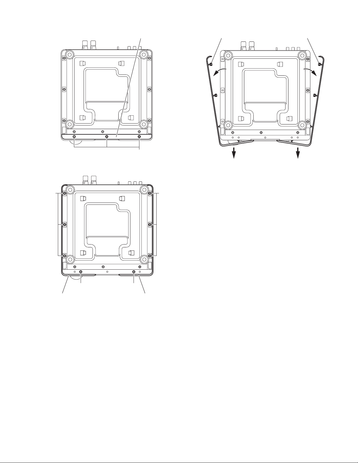
Wood ba
r
111 111
F
Fig.5
2 2
Fig.7
GG
AL panel LAL panel R
AL panel R
H H
AL panel L
Fig.6
(No.MB348)1-9
Page 10

3.1.3 Removing the front panel assembly
y
(See Fig.8)
• Remove the top cover, AL panel L and AL panel R.
(1) Removing the three screws J attaching the front panel as-
sembly. (See Fig.8.)
(2) Release the claws a attaching the front panel assembly
and remove the front panel assembly in the direction of the
arrow. (See Fig.8.)
Note:
When attaching the front panel assembly, confirm that the connector CN804
nector CN704 on the micom board certainly.
on the front board is disconnected in the con-
Front panel assembl
CN704
a
CN804
J
Fig.8
a
J
1-10 (No.MB348)
Page 11

3.1.4 Removing the rear panel
(See Fig.9.)
From the back side of the main body, remove the sixteen screws
K and screw L attaching the rear panel.
3.1.5 Removing the switching power unit
(See Figs.9 and 10)
• Remove the top cover, AL panel L and AL panel R.
(1) From the back side of the main body, remove the screw L
attaching the switching power unit. (See Fig.9.)
(2) From the right side of the main body, disconnect the wire
from the connector CN201
Fig.10.)
(3) Remove the screw M attaching the switching power unit.
(See Fig.10.)
(4) From the top side of the switching power unit, remove the
spacer fixing the lug wire. (See Fig.10.)
(5) Take out the switching power unit from the main body in the
direction of the arrow. (See Fig.10.)
on the main board. (See
K
Rear panel
KL
Fig.9
Spacer
CN201
Wire
Lug wire
M
Main board
Switching power unit
Fig.10
(No.MB348)1-11
Page 12

3.1.6 Removing the tuner
(See Figs.11 and 12)
• Remove the top cover and rear panel.
(1) From the top side of the main body, remove the two screws
N attaching the bridge C. (See Fig.11.)
Reference:
When attaching the screws N, attach the lug wires with
them. (See Fig.11.)
(2) Release the claws b of the tuner holder and take out the
tuner from the main body. (See Fig.12.)
(3) Disconnect the card wire from the connector CN1
tuner. (See Fig.12.)
on the
N
Lug wire Bridge C
Fig.11
Tuner
b
N
Lug wire
b
1-12 (No.MB348)
CN1
Card wire
Fig.12
Page 13

3.1.7 Removing the headphone board
(See Fig.13)
• Remove the top cover, AL panel L, AL panel R and front panel
assembly.
(1) From the left side of the main body, disconnect the wire
from the connector CN401
(2) Remove the screw P attaching the headphone board.
(3) Remove the engagement section c toward this side, re-
move the headphone board from the joint d in the direction
of the arrow.
on the main board.
P
Main board
c
d
Fig.13
Headphone board
CN401
(No.MB348)1-13
Page 14

3.1.8 Removing the main board
A
R
(See Figs.14 and 15)
• Remove the top cover, AL panel L, AL panel R, rear panel and
switching power unit.
Reference:
Remove the front panel assembly as required.
(1) From the top side of the main body, disconnect the card
wires from the connectors (CN202
main board. (See Fig.14.)
(2) Disconnect the wires from the connectors (CN205
) on the main board. (See Fig.14.)
CN401
(3) Disconnect the wire from the connector CN706 on the mi-
com board. (See Fig.14.)
(4) Disconnect the wires from the connectors (CN310
CN312) on the digital amplifier board assembly. (See
Fig.14.)
(5) Remove the screw Q attaching the lug wire to the bracket
A. (See Fig.14.)
(6) Disconnect the lug wire from TP201
(See Fig.14.)
(7) Remove the spacer fixing the lug wire. (See Fig.15.)
(8) Remove the four screws R attaching the main board and
remove the main board from the main body. (See Fig.15.)
Reference:
When attaching the main board, attach the screws R after fitting the hole of the main board to the joints e and f of the main
body. (See Fig.15.)
and CN204) on the
and
and
on the main board.
Digital amplifier
board assembly
CN312
CN310
Wire
Micom board
Wires
CN401
Main board
CN204
CN706
CN202
Lug wire
Card wire
CN205
Wire
Card wire
Bracket
Q
TP201
Main board
TP201
Lug wire
Fig.14
Spacer
e
R
1-14 (No.MB348)
Lug wire
R
Main board
f
Fig.15
Page 15

3.1.9 Removing the micom board
(See Figs.16 and 17)
• Remove the top cover, AL panel L, AL panel R, front panel as-
sembly, rear panel, switching power unit and main board.
(1) From the top side of the main body, disconnect the card
wires from the connectors (CN631
com board. (See Fig.16.)
(2) Disconnect the card wire from the connector CN705
micom board and take out the tuner after releasing the
claws g of the tuner holder. (See Fig.16.)
Reference:
Remove the tuner as required.
(3) Disconnect the wire from the connector CN311
ital amplifier board assembly. (See Fig.16.)
(4) Disconnect the card wire from the connector CN601
main board. (See Fig.17.)
(5) Remove the two screws S and screw S' attaching the mi-
com board. (See Fig.17.)
Reference:
• When attaching the screw S', attach the bracket D with it.
(See Fig.17.)
• When attaching the micom board, attach the screws S and
screw S' after fitting the hole of the micom board to the joints
(h,i,j,k) of the main body. (See Fig.17.)
and CN701) on the mi-
on the
on the dig-
on the
Tuner
CN705
CN311
CN701
Digital amplifier board assembly
Tuner holder
g
Card wire
Wire
Fig.16
Card wires
CN631
Micom board
Micom
board
i
CN601
Card wire
S'
h
Micom board
Bracket D
Micom board
j
S
k
S
Micom board
Fig.17
(No.MB348)1-15
Page 16

3.1.10 Removing the digital amplifier board
(See Figs.18 to 20)
• Remove the top cover, AL panel L, AL panel R, front panel as-
sembly, rear panel, switching power unit, main board and micom board.
(1) From the back side of the main body, disconnect the card
wire from the connector CN313
board assembly. (See Fig.18.)
Reference:
When connecting the wire, connect the wire to connector
on the digital amplifier board assembly after pass
CN313
it through the section m of the side cover L. (See Fig.18.)
(2) From the top side of the main body, remove the two screws
T and two screws U attaching the bracket C. (See Fig.18.)
(3) Take out the bracket C with the headphone board from the
main body.
Reference:
When attaching the bracket C to the bottom chassis, attach it after fitting the hole to the projections n of the bot-
tom chassis. (See Fig.18.)
(4) Take out the digital amplifier board assembly.
(5) Release the joints (p,q,r) of the deus case A and deus case
B, and remove the deus case A in the direction of the ar-
row. (See Fig.19.)
(6) Remove the screw V attaching the heat sink. (See Fig.20.)
(7) Remove the solder from the soldered sections (s,t) attach-
ing the digital amplifier board to the deus case B and bend
the joints (u,v) in the direction of the arrow. (See Fig.20.)
(8) Take out the digital amplifier board from the deus case B.
Reference:
When attaching the digital amplifier board to the deus case B,
fit the joints (u,v,w,x) of the deus case B to the hole of the digital amplifier board. (See Fig.20.)
on the digital amplifier
s
Deus case A
p
Deus case B
u
r
q
Fig.19
Digital amplifier board
V
x
Side cover L
Wire
CN313
U
n
T
U
Headphone board
T
m
Digital amplifier board assembly
Fig.18
Bottom chassis
Bracket C
w
t
Deus case B
Fig.20
Heat sink
v
1-16 (No.MB348)
Page 17

3.1.11 Removing the speaker terminal board
YY
(See Fig.21.)
• Remove the top cover, AL panel L, AL panel R, front panel assembly, the rear panel, switching power unit, main board and
micom board.
(1) From the back side of the main body, disconnect the wire
from the connector CN313
sembly.
Reference:
When connecting the wire, connect the wire to connector
on the digital amplifier board assembly after pass
CN313
it through the section y of the side cover L. (See Fig.21.)
(2) From the top side of the main body, remove the screw W
attaching the speaker terminal board.
Reference:
When attaching the speaker terminal board, attach the screw
W after fitting the hole of the speaker terminal board to the joint
z of the side cover R.
3.1.12 Removing the component video terminal board
(See Fig.21)
• Remove the top cover, AL panel L, AL panel R, front panel assembly, rear panel, switching power unit, main board and micom board.
From the top side of the main body, remove the screw X attaching the component video terminal board.
Reference:
When attaching the component video terminal board, attach
the screw X after fitting the hole of the component video terminal board to the joint aa of the side cover L.
on the digital amplifier board as-
Component video terminal board
aa
Side cover L
Digital amplifier board assembly
CN313
Wire
X
y
Fig.21
Speaker terminal board
Side cover R
W
z
3.1.13 Removing the DVD mechanism assembly
(See Fig.22.)
• Remove the top cover, AL panel L, AL panel R, front panel assembly, rear panel, switching power unit, main board and the
micom board.
(1) From the top side of the main body, remove the three
screws Y attaching the DVD mechanism assembly.
(2) Take out the DVD mechanism assembly from the main
body.
Y
DVD mechanism assembly
Fig.22
(No.MB348)1-17
Page 18

3.1.14 Removing the front board
(See Figs.23 and 24)
• Remove the top cover, AL panel L, AL panel R and front panel
assembly.
(1) From the front side of the front panel assembly, pull out the
volume assembly in the direction of the arrow. (See
Fig.23.)
(2) From the inside of the front panel assembly, remove the
ten screws Z attaching the front board. (See Fig.24.)
(3) Release the two claws ab of the indicator attaching the
front board and take out the front board from the front panel
assembly. (See Fig.24.)
Reference:
When attaching the front board, attach the screws Z after fitting
the hole of the front board to the projections ac of the front panel assembly. (See Fig.24.)
Volume assembly
ac
Front panel assembly
Fig.23
Front board
ac
ac
Z Z
Z
Front panel assembly
Fig.24
ab
ac
Z
1-18 (No.MB348)
Page 19

3.2 DVD mechanism section
• Remove the DVD mechanism assembly from the main body.
(See "3.1.13 Removing the DVD mechanism assembly".)
3.2.1 Removing the traverse mechanism assembly
(See Fig.1)
• From the bottom side of the DVD mechanism assembly, re-
move the three screws A and screw A’ attaching the traverse
mechanism assembly and take out the DVD traverse mechanism assembly with the DVD servo control board.
Reference:
When attaching the screws A’, attach the washer with it.
DVD mechanism assembly
DVD servo control board
A'
Washer
A'
3.2.2 Removing the DVD servo control board
(See Figs.2 and 3)
• Remove the traverse mechanism assembly.
(1) From the side of the traverse mechanism assembly, solder
the short land sections a on the pickup. (See Fig.2.)
(2) From the bottom side of the traverse mechanism assem-
bly, release the lock of the connector CN101
servo control board in the direction of the arrow and disconnect the card wire. (See Fig.3.)
Caution:
• Solder the short land sections a on the pickup before
disconnecting the card wire from the connector CN101
on the DVD servo control board. If the card wire is disconnected without attaching solder, the pickup may be
destroyed by static electricity. (See Figs.2 and 3.)
• When attaching the DVD servo control board, be sure
to remove solders from the short land sections a after
connecting the card wire to the connector CN101
the DVD servo control board. (See Figs.2 and 3.)
(3) Disconnect the card wire from the connector CN201
DVD servo control board. (See Fig.3.)
(4) Remove the two screws B attaching the DVD servo control
board. (See Fig.3.)
(5) Remove the DVD servo control board from the engage-
ment section b in an upward and remove the engagement
section d in the direction 2 while removing the engagement
section c in the direction of the arrow 1. (See Fig.3.)
on the DVD
on the
on
A
Traverse mechanism assembly
Fig.1
a
Traverse mechanism assembly
Fig.2
Card wire
b
CN101
B
1
Pickup
Card wire
2
A
CN201
B
d
c
DVD servo control board
Traverse mechanism assembly
Fig.3
(No.MB348)1-19
Page 20

3.2.3 Removing the pickup
(See Figs.2,4 to 6)
• Remove the traverse mechanism assembly.
(1) From the side of the traverse mechanism assembly, solder
the short land sections a on the pickup. (See Fig.2.)
(2) Release the lock of the connector on the pickup in the di-
rection of the arrow and disconnect the card wire. (See
Fig.4.)
Caution:
• Solder the short land sections a on the pickup before
disconnecting the card wire from the connector on the
pickup. If the card wire is disconnected without attaching solder, the pickup may be destroyed by static electricity. (See Figs.2 and 4.)
• When attaching the pickup, be sure to remove solders
from the short land sections a after connecting the
card wire to the connector on the pickup. (See Figs.2
and 4.)
(3) Remove the screw C attaching the plate and thrust spring.
(See Fig.4.)
(4) Remove the engagement section e attaching the plate to
the feed holder and remove the plate with the thrust spring.
(See Fig.4.)
(5) Remove the shaft of the pickup from the section f on the
traverse mechanism assembly and remove the shaft from
the section g while moving it in the direction of the arrow.
(See Fig.5.)
(6) Remove the pickup from the section h of the traverse
mechanism assembly and take out the pickup with the
shaft. (See fig.5.)
(7) From the bottom side of the pickup, remove the two screws
D attaching the SW actuator and leaf spring. (See Fig.6.)
(8) Pull the shaft out of the pickup. (See Fig.6.)
Plate
C
Feed holder
f
e
Thrust spring
Card wire
Traverse mechanism assembly
Shaft
Connector
Fig.4
Torsion spring
Pickup
g
1-20 (No.MB348)
Pickup
h
Fig.5
Pickup
SW actuator
Shaft
Leaf spring
D
Fig.6
Page 21

3.2.4 Attaching the pickup
(See Figs.2,4 to 7)
• See "3.2.3 Removing the pickup"
(1) Attach the shaft, SW actuator and leaf spring to the pickup.
(See Fig.6.)
(2) Align the pickup to the section h of the traverse mechanism
assembly first, and set the both ends of the shaft of the
pickup in the sections f and g of the traverse mechanism
assembly. (See Fig.5.)
Reference:
When attaching the shaft to the section g, attach it under
the torsion spring. (See Fig.5.)
(3) Attach the plate and thrust spring. (See Fig.4.)
(4) Remove solders from the short land sections a after con-
necting the card wire to the connector on the pickup. (See
Figs.2 and 4.)
(5) Turn the feed gear M in the direction of the arrow 1 to move
the pickup fully in the direction of the arrow 2. (See Fig.7.)
Feed gear M
1
2
Pickup
Fig.7
(No.MB348)1-21
Page 22

3.2.5 Removing the feed motor
(See Figs.4,8 and 9)
• Remove the traverse mechanism assembly.
(1) From the top side of the traverse mechanism assembly, re-
move the screw C attaching the plate and thrust spring.
(See Fig.4.)
(2) Remove the engagement section e attaching the plate to
the feed holder and remove the plate with the thrust spring.
(See Fig.4.)
(3) Remove the wires from the soldered section i on the spin-
dle motor board. (See Fig.8.)
Reference:
• When attaching the feed motor, pass the wire through
the section j on the spindle base. (See Fig.8.)
• Pass the wire through the lower section of the torsion
spring. (See Fig.8.)
(4) Remove the feed holder, feed motor, lead screw, feed gear
E and feed gear M at the same time after removing the
three screws E attaching the feed holder. (See Fig.8.)
(5) From the side of the feed holder, remove the two screws F
attaching the feed motor. (See Fig.9.)
Feed gear M
Feed gear E
E
Feed motor
Lead screw
Torsion spring
Wires
j
i
3.2.6 Removing the spindle motor board
(See Figs.8 and 10)
• Remove the traverse mechanism assembly and DVD servo
control board.
(1) From the top side of the traverse mechanism assembly, re-
move the wires from the soldered section i on the spindle
motor board. (See Fig.8.)
(2) From the bottom side of the traverse mechanism assem-
bly, remove the three screws G attaching the spindle motor
board. (See Fig.10.)
E
Feed holder
Traverse mechanism assembly
Spindle base
Spindle motor board
Fig.8
F
Fig.9
Traverse mechanism assembly
Feed holder
1-22 (No.MB348)
G
Fig.10
Page 23

3.2.7 Removing the switch board
(See Fig.11.)
(1) From the bottom side of the DVD mechanism assembly, re-
move the wires from the soldered sections k on the switch
board.
(2) Lift the switch board while pressing the claw m of the DVD
mechanism assembly in the direction of the arrow and remove it from the section n.
Reference:
• Put the wires on the section p after attaching the switch
board to the DVD mechanism assembly.
• Fix the claw m on the DVD mechanism assembly with bonds
after attaching the switch board.
3.2.8 Removing the motor
(See Figs.11 to 15)
(1) From the bottom side of the DVD mechanism assembly, re-
move the wires from the soldered section k on the switch
board. (See Fig.11.)
(2) From the right side of the DVD mechanism assembly, push
the slide cam and pull the tray assembly out of the DVD
mechanism assembly in the direction of the arrow. (See
Fig.12.)
(3) From the top side of the DVD mechanism assembly, re-
move the two screws H attaching the leaf spring to the
bushing and remove the leaf spring. (See Fig.13.)
(4) Remove the bushing of the tray assembly from the projec-
tion q on the DVD mechanism assembly and move the tray
assembly in the direction of the arrow. (See Fig.14.)
(5) Remove the claw r of the tray assembly from the DVD
mechanism assembly and take out the tray assembly. (See
Fig.14.)
(6) From the top side of the DVD mechanism assembly, re-
move the belt from the motor pulley. (See Fig.15.)
Note:
Take care not to attach grease on the belt.
(7) Remove the two screws J attaching the motor to the DVD
mechanism assembly and take out the motor from the bottom side of the DVD mechanism assembly. (See Fig.15.)
Reference:
Put the wires on the section p after attaching the motor to the
DVD mechanism assembly. (See Fig.11.)
DVD mechanism assembly
Switch board Wires
k
m
Tray assembly
Slide cam
Fig.12
Leaf spring
DVD mechanism assembly
Fig.13
q
r
DVD mechanism assembly
Fig.14
DVD mechanism assembly
DVD mechanism assembly
H
Tray assembly
Bushing
Bushing
n
p
Fig.11
J
Fig.15
Belt
Motor pulley
(No.MB348)1-23
Page 24

4.1 Jigs and test instruments
• Remote controller
• Test disc : VT501, VT502
4.2 Adjustment and check method
While pressing both the [STOP] key and
[PLAY/PAUSE] key on the main unit,
insert the AC power cord in an outlet.
SECTION 4
ADJUSTMENT
Indication
TES 3U0
3
or
TES 3U3h
3
Press the [MENU] key on
the remote controller.
Indication
XXXX
Press the [MENU] key on
the remote controller.
Area suffix indication
1:JC
7:UB 8:UT 9:4U 10:UY 11:EE 12:UF
Region indication
Received region data are assigned by a bit unit.
When 1 is made more than 2 bits, HEX displays a region number
and distinguishes it by displaying h.
Index indication of device key
(For DVD-Audio)
2:1U 3:D 4:E 5:2U 6:3U
Bit0:Region 1
Bit1:Region 2
Bit2:Region 3
Bit3:Region 4
Bit4:Region 5
Bit5:Region 6
Bit6:Region 7
Bit7:Region 8
A
1-24 (No.MB348)
Indication
X.XX XX
SC:
B
Version indication of system control microcomputer
SYS : System control microcomputer
A version of a ROM collection is displayed in the right side of version
indication of a system control microcomputer.
Press the [ON SCREEN]
key on the remote controller.
Indication
XXX
UT:
PLAY/PAUSE
DVD EJECT
Version indication of unit
Indication returns to version indication of a system control
microcomputer by pushing an ON SCREEN key again.
STOP
Page 25

A
Press the [MENU] key on
the remote controller.
B
Check mode starts of
the front end.
Indication
CHECK
FE:
Press the [1] key on
the remote controller.
Indication
CHECK
PLY
Press the [2] key on
the remote controller.
Indication
XXXXXXXX
WOB
Press the [3] key on
the remote controller.
Indication
CHECK
Disc startup and through playback
(Playback starts from the start position)
CD TNO+1 search
CD TNO-1 search
Press the [4] key on
the remote controller.
Indication
XXXXYYYY
CD_LD lights and laser current is displayed.
XXXXYYYY
CD
Jitter value
Laser current value
Press the [5] key on
the remote controller.
Indication
XXXXYYYY
DVD_LD lights and laser current is displayed.
XXXXYYYY
DVD
Jitter value
Laser current value
D EC
(No.MB348)1-25
Page 26

D EC
Press the [6] key on
the remote controller.
Indication
XXXXYYYY
JIT
Press the [7] key on
the remote controller.
Indication
XXXXYYYY
-1
Press the [8] key on
the remote controller.
Indication
XXXXYYYY
+1
DVD x2 jitter measuring mode
XXXXYYYY
Jitter value
Laser current value
Contents of EEPROM used by mechanism
control microcomputer (An address is done -1 of.)
XXXXYYYY
EEPROM data
EEPROM address
Contents of EEPROM used by mechanism
control microcomputer (An address is done +1 of.)
XXXXYYYY
EEPROM data
EEPROM address
Press the [9] key on
the remote controller.
Indication
XXXXYYYY
TMP
Press the [10] key on
the remote controller.
Indication
XXXXYYYY
DLO
G HF
Search & jitter measurement of the specified
position of DVD-SL
XXXXYYYY
Jitter value
Position measured with VT-502
Search & jitter measurement of the specified
position of opposite disc of DVD-DL
XXXXYYYY
Jitter value
Position measured with VT-501
1-26 (No.MB348)
Page 27

G HF
Press the [0] key on
the remote controller.
Indication
XXXXYYYY
MON
Press the [+10] key on
the remote controller.
Search & jitter measurement of the specified
position of parallel disc of the DVD-DL
XXXXYYYY
Indication
MECH CPU
CLA
Press the [STOP] key on the main
unit or remote controller.
Indication
CHECK
Disc stopped & LD-OFF
STP
Jitter value
Position measured with VT-501
Initialization of EEPROM contents used by
the mechanism control microcomputer
Press the [DVD EJECT]
key on the main unit.
Indication
Tray OPEN/CLOSE
CHECK
O/C
Press the [DVD PLAY] key on the
main unit or remote controller.
Indication
XXXXYYYY
Disc playback
XXXXYYYY
PLY
Press the [MENU] key on
the remote controller.
Cancellation of a test mode
Push the [STANDBY] key on the main unit or remote controller.
Cancellation of a test mode can execute any step in adjustment.
Jitter value
Laser current value
(No.MB348)1-27
Page 28

SECTION 5
TROUBLESHOOTING
This service manual does not describe TROUBLESHOOTING.
1-28 (No.MB348)
Page 29

(No.MB348)1-29
Page 30

Victor Company of Japan, Limited
AV & MULTIMEDIA COMPANY AUDIO/VIDEO SYSTEMS CATEGORY 10-1,1chome,Ohwatari-machi,Maebashi-city,371-8543,Japan
(No.MB348)
Printed in Japan
VPT
 Loading...