

JVC DT-V100CGU - Hdtv Multi-format Monitor, V100CGU - Video Editing Monitor CRT Display DT 10 Inch Professional Production, DT-V100CG Basic Manual
Page 1
DT-V100CG Menu Operations
Basic Manual
HD format including SDI can simply be displayed on this 10” CRT
Features
I. : HD / SD (SDI, component*)
II. : HD / SD Format can be converted to Video Signal
III. : No delay due to L INE conversion
IV. : Using CRT of SD
*Advantage ; Viewing Angle / Response Time / Low Price
*Disadvantage ; Power Consumption (45w actual)
V. Without above, almost same as DT-V19/17
(Marker / Level Meter / Underscan / Rush Display / Zoom / RS485Remote)
*Add. Function; Level Meter Function (During Zoom), Format Indicator Function
*No Function; Pulse Check Function
* Scheduled early 2006
Page 2
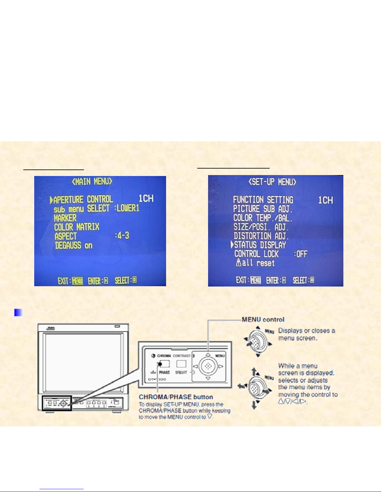
MAIN MENU
SET-UP MENU
Buttons for Menu Operations
Page 3
Page 4
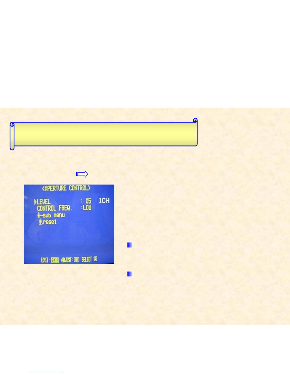
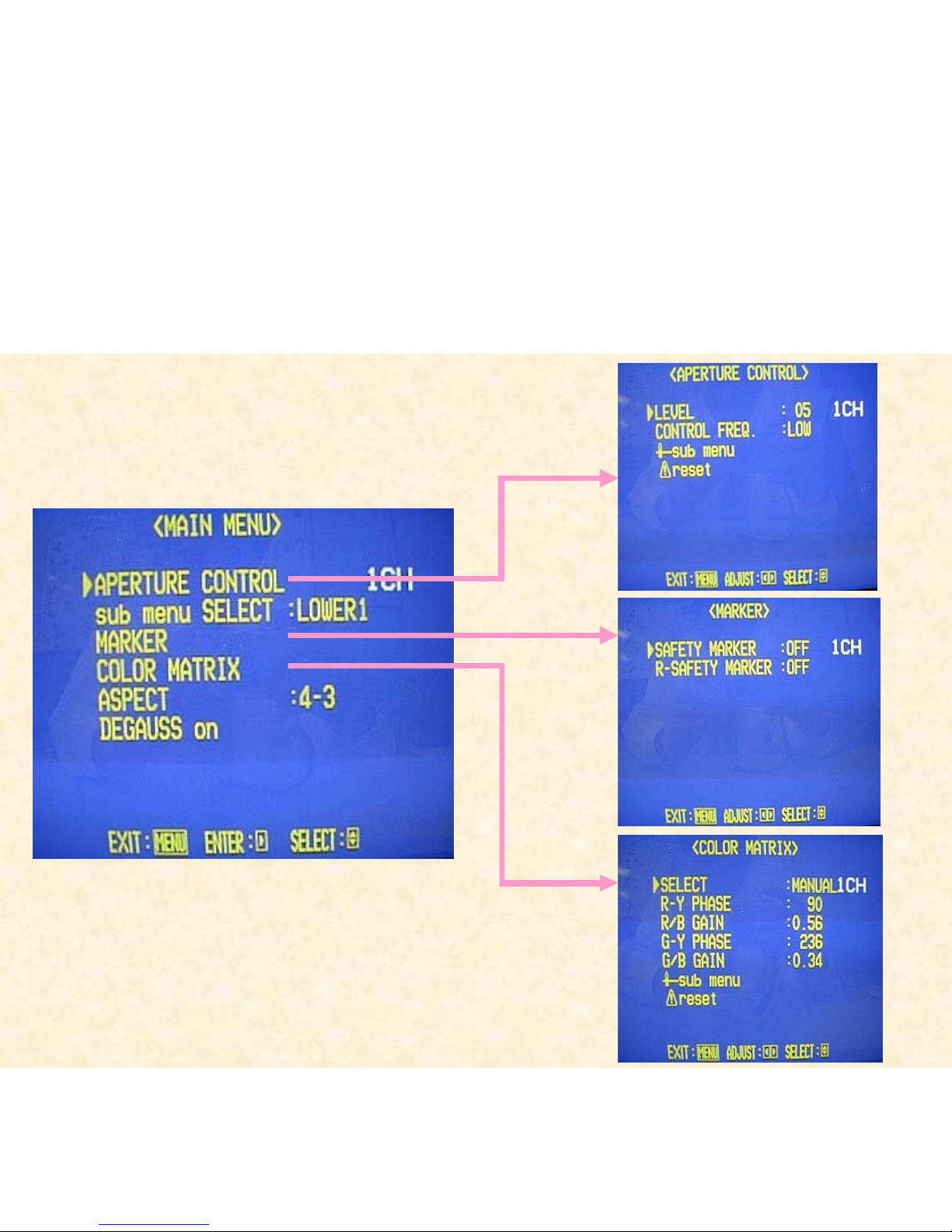
MAIN MENU APERTURE CONTROL
Compensates the frequency
characteristics of the input
video signal.
LEVEL
Adjusts the compensate value.
CONTROL FREQ.
Selects the frequency to compensate.
How to Use Main Menu
Page 5
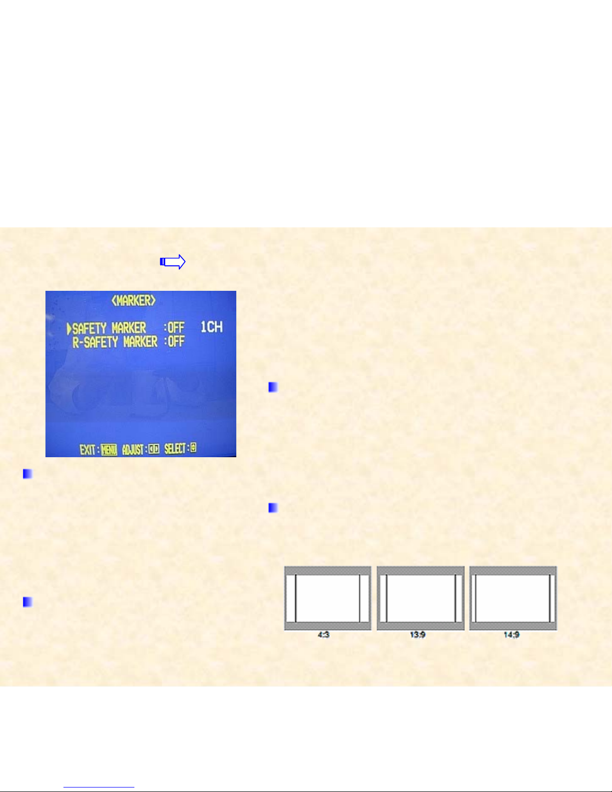
MAIN MENU MARKER
Controls ON / OFF and other Settings of the MARKER
SELECT, ZOOM, ASPECT SELECT, and SAFETY
MARKER functions Included in the MARKER Function.
MARKER SELECT
R-MARKER SELECT
It displays the area of the aspect ratio
that has been set in the ASPECT
SELECT / R-ASPECT SELECT,
superimposed on the current screen.
ZOOM / R-ZOOM
Zooms the area of 4:3 aspect ratio to
fill the whole screen when the signal
of 16:9 format is input.
SAFETY MARKER / R-SEFERY MARKER
Displays dotted lines to indicate the areas
corresponding to 80%, 88%, or 90% of the screen
size (the aspect ratio setting in “ASPECT
SELECT/R-ASPECT SELECT)
ASPECT SELECT/R-ASPECT SELECT
Selects the aspect ratio.
• 4:3/13:9/14:9
Page 6

MAIN MENU COLOR MATRIX
Selects or adjusts the standard of the
Color demodulation (color rendering).
SELECT
Selects the picture matrix standard.
R-Y PHASE
Sets the R-Y phase.
R/B GAIN
Sets the R/B gain.
G-Y PHASE
Sets the G-Y phase.
G/B GAIN
Sets the G/B gain.
Page 7

MAIN MENU ASPECT
Selects the aspect ratio.
MAIN MENU DEGAUSS on
Degausses the screen.
While degaussing, “Degaussing!” is displayed on the screen.
4 : 3 16 : 9
Page 8

Page 9

SET-UP MENU FUNCTION SETTING
Sets the control systems for the
COLOR SYSTEM, synchronized
signal, RUSH DELAY TIME,
colors and functions of the tally
lamp, groups of the audio output
modes, and MAKE/TRIGGER
terminal.
How to Use SET-UP Menu
Page 10

COLOR SYSTEM
Selects the color system.
SYNC SELECT
Selects the synchronized signal
RUSH DELAY TIME
Sets the delay time between when
the stand-by button is pressed and
when the monitor actually turns on.
TALLY SELECT
Selects the color of the tally lamp
on the upper right of the front panel.
FORMAT IND.
Sets the tally lamp as the format
indicator to show the format of the
signal currently input.
ON: Uses the lamp as the format indicator.
Green: Shows the HD SDI signal is input.
Re d : Shows the SD SDI Signal is input.
Orange: Shows the composite signal is input.
OFF: Uses the lamp as the tally lamp.
REMOTE SYSTEM
Sets the MAKE / TRIGGER terminal.
ZOOM WINDOW
Adjusts the horizontal position of the
zooming area. This item appears on
the menu only when using the
Component Unit (option).
E. AUDIO GROUP
Sets the group of the available audio
output modes selected by the MENU
control.
HOUR METER X 100h
Displays the total usage time of the
monitor in hundred-hour units.
Page 11

SET-UP MENU PICTURE SUB ADJ.
The standard value (“00”) of the
picture adjustment is initially set at the
factory. You can adjust the standard
value as your initial setting.
CONTRAST
BRIGHT
CHROMA
PHASE
NTSC SET UP
Sets the set-up level of the input
NTSC signal.
COMPO. LEVEL
Sets the set-up level of the input
component or SD DDI signal.
Page 12

SET-UP MENU COLOR TEMP. / BAL.
Sets or adjusts the color temperature
or white balance.
COLOR TEMP.
Selects the color temperature.
BLUE DRIVE
Adjusts the blue drive level.
RED DRIVE
Adjusts the red drive
GREEN CUTOFF
Adjusts the green cut-off point.
BLUE CUTOFF
Adjusts the blue cut-off point.
RED CUTOFF
Adjusts the red cut-off point.
Page 13

SET-UP MENU SIZE / POSI. ADJ.
Adjusts the size or position of the
picture.
H. SIZE
Adjusts the horizontal screen size
H. POSITION
Adjusts the horizontal screen position.
V. SIZE
Adjusts the vertical screen size.
V. POSITION
Adjusts the vertical screen size
ZOOM H. SIZE
ZOOM V. SIZE
Page 14

SET-UP MENU DISTORTION ADJ.
Compensates the picture distortion,
tilt, and the color heterogeneity
caused by the geomagnetic influence.
PARALLELOGRAM
Compensates the parallelogram
picture distortion.
TRAPEZOID
Compensates the trapezoid picture
distortion
ROTATION
Compensates a picture tilt.
PURITY
According to the location of the
monitor, there may be the color
heterogeneity around the rim of the
screen caused by the geomagnetic
influence. You can avoid this color
heterogeneity with this function
decreasing the geomagnetic
influence.
Page 15

SET-UP MENU STATUS DISPLAY
Sets the items related to the display screens, such as
the status display or the AUDIO LEVEL METER display.
Can also be used to set the 1080/60i or 1035/60i signal
displayed correctly.
1080 / 1035
When the component signal is input,
the monitor does not automatically
discriminate the 1080/60i signal from
the 1035/60i signal. Set this item
according to the input signal format.
This item appears on the menu only
when using the Component Unit
(option). 1080 / 1035
STATUS DISPLAY
Sets the status display.
AUTO / MANUAL / OFF
Setting the AUDIO LEVEL METER display
You can check the conditions of the current EMBEDDED
AUDIO signals on the AUDIO LEVEL METER display.
AUDIO LEVEL METER display example
LEVEL METER ch: 1-8, BAR TYPE: 3COLORS
Page 16

SET-UP MENU CONTROL LOCK
CONTROL LOCK
Prohibits the monitor operations except turning on/off the monitor and
deactivating this function.
SET-UP MENU all reset
Resets all SET-UP MENU items to factory-preset values.
 Loading...