

Page 1
.
INPUT
PHOTO
http://manual3.jvckenwood.com/projector/mobile/global/
The Mobile User Guide can be viewed on mobile internet devices including
smartphones and tablets.
Mobile User Guide
Pour utilisation par le client :
Entrerci-dessous le N°de série qui
est situé sous le boîtier. Garder
cetteinformation comme référence
pour le futur.
Instrucción para el cliente :
Introduzca a continuación el nº de
serie que aparece en la parte
inferior lateral de la caja. Conserve
esta información como referencia
para uso ulterior.
For Customer use :
Enter below the serial No. which is
located on the side of the cabinet.
Retain this information for future
reference.
DLA-X900R / DLA-X700R /
DLA-X500R
Model No.
Serial No.
DLA-X900R / DLA-X700R /
DLA-X5
00R
N° de modèle
N° de série
DLA-X900R / DLA-X700R /
DLA-X500R
Modelo Nº
Nº de serie
D-ILA
PROJECTOR
DLA-X900R
DLA-X700R
DLA-X500R
ENGLISH
FRANÇAIS
ESPAÑOL/CASTELLANO
Getting Started Set up Operate Adjust/Set Maintenance Troubleshooting Others
INSTRUCTIONS
.
.
.
Not suitable for household room illumination.
PC027183199-1
Page 2
Safety Precautions
晼㯡婌♟㒷
IMPORTANT INFORMATION
This product has a High Intensity
Dis-charge (HID) lamp that contains
mercury.
Disposal of these materials may be
regulated in your community due to
environmental considerations. For
disposal or recycling information,
please contact your local authorities or
for USA, the Electronic Industries
Alliance: http://www.eiae.org.
WARNING:
TO PREVENT FIRE OR SHOCK HAZARDS, DO
NOT EXPOSE THIS APPLIANCE TO RAIN OR
MOISTURE.
MACHINE NOISE INFORMATION
(Germany only)
Changes Machine Noise Information Ordinance 3.
GSGV, January 18, 1991: The sound pressure level
at the operator position is equal or less than 20 dB
(A) according to ISO 7779.
FCC INFORMATION (U.S.A. only)
CAUTION:
Changes or modification not approved by JVC could
void the user’s authority to operate the equipment.
About the installation place
Do not install the projector in a place that cannot
support its weight securely.
If the installation place is not sturdy enough, the
projector could fall or overturn, possibly causing
personal injury.
Reorient or relocate the receiving antenna.
Increase the separation between the equipment
and receiver.
Consult the dealer or an experienced radio/TV
technician for help.
Connect the equipment into an outlet on a circuit
different from that to which the receiver is
connected.
NOTE:
This equipment has been tested and found to comply
with the limits for Class B digital devices, pursuant to
Part 15 of the FCC Rules. These limits are designed
to provide reasonable protec tion against harmful
interference in a residential installation. This
equipment generates, uses, and can radiate radio
frequency energy and, if not installed and used in
accordance with the instruc tions, may cause harmful
interference to radio communications. However,
there is no guarantee that interference will not occur
in a particular installation. If this equipment does
cause harmful interference to radio or television
reception, which can be determined by turning the
equipment off and on, the user is encourage to try to
correct the interference by one or more of the
following measures:
WARNING:
THIS APPARATUS MUST BE EARTHED.
CAUTION:
For the customers in Taiwan only
To reduce the risk of electric shock, do not remove
cover. Refer servicing to qualified service personnel.
This projector is equipped with a 3-blade grounding
type plug to satisfy FCC rule. If you are unable to
insert the plug into the outlet, contact your electrician.
Model Number: DLA-X900RBU/DLA-X700RBU/
DLA-X500RBU
Trade Name: JVC
Responsible party: JVC AMERICAS CORP.
Address: 1700 Valley Road Wayne, N. J. 07470
Telephone Number: 973-317-5000
This device complies with Part 15 of FCC Rules.
Operation is subject to the following two conditions:
(1) This device may not cause harmful interference,
and (2) this device must accept any interference
received, including interference that may cause
undesired operation.
Declaration of Conformity
Getting Started
.
2
Page 3
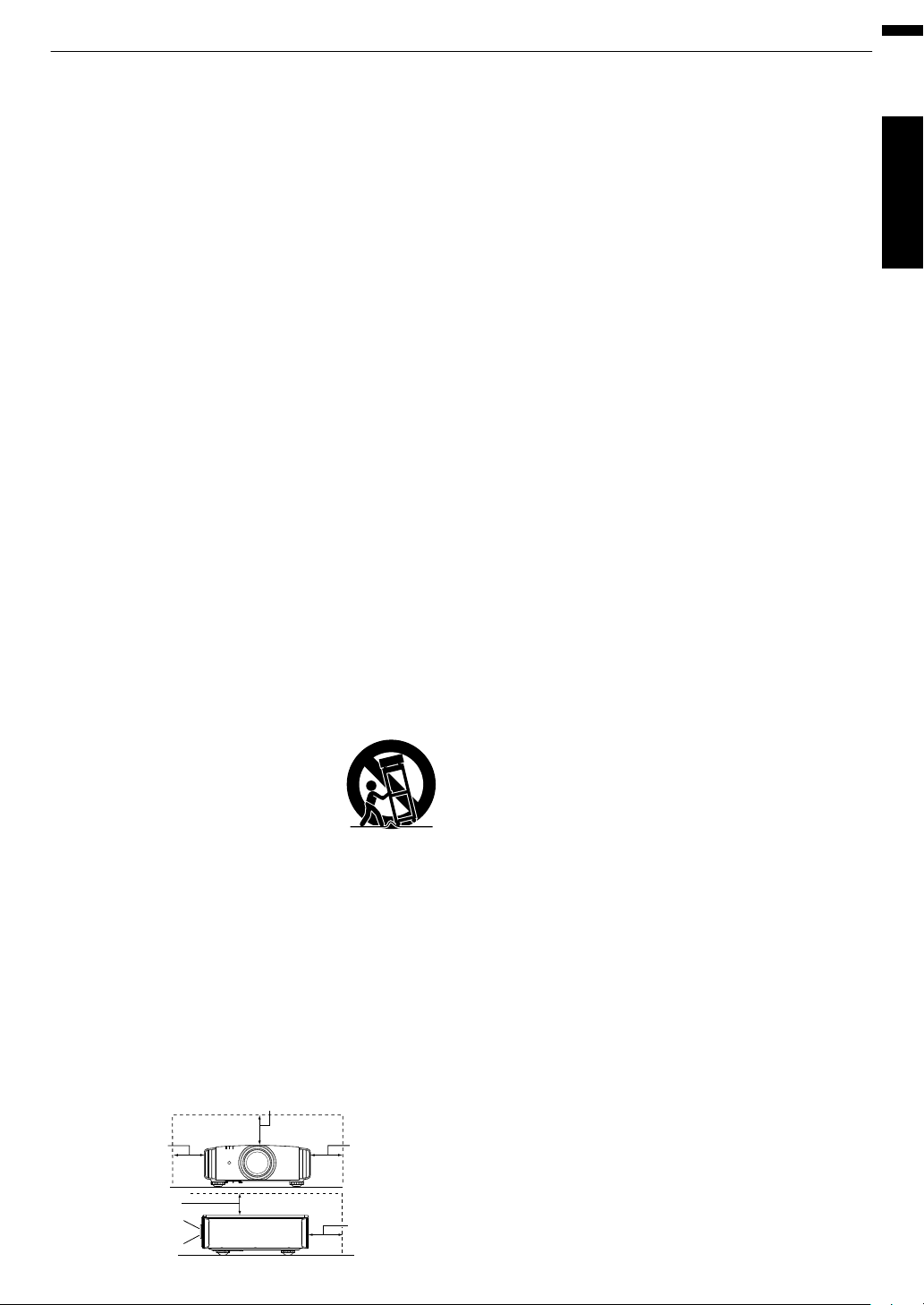
150 mm and above
150 mm
and above
300 mm
and above
200 mm
and above
300 mm
and above
PORTABLE CART WARNING
(symbol provided by RETAC)
S3126A
Front
-
-
-
-
-
-
-
-
-
-
-
-
-
IMPORTANT SAFEGUARDS
Electrical energy can perform many useful functions.
This unit has been engineered and manufactured to
assure your personal safety. But IMPROPER USE
CAN RESULT IN POTENTIAL ELECTRICAL
SHOCK OR FIRE HAZARD. In order not to defeat
the safeguards incorporated into this product,
observe the following basic rules for its installation,
use and service. Please read these Important
Safeguards carefully before use.
All the safety and operating instructions should be read
before the product is operated.
The safety and operating instructions should be retained for
future reference.
All warnings on the product and in the operating
instructions should be adhered to.
All operating instructions should be followed.
Place the projector near a wall outlet where the plug can be
easily unplugged.
Unplug this product from the wall outlet before cleaning.
Do not use liquid cleaners or aerosol cleaners. Use a damp
cloth for cleaning.
Do not use attachments not recommended by the product
manufacturer as they may be hazardous.
Do not use this product near water. Do not use immediately
after moving from a low temperature to high temperature,
as this causes condensation, which may result in fire,
electric shock, or other hazards.
Do not place this product on an unstable cart, stand, or
table. The product may fall, causing serious injury to a child
or adult, and serious damage to the product. The product
should be mounted according to the manufacturer’s
instructions, and should use a mount recommended by the
manufacturer.
When the product is used on a cart,
care should be taken to avoid quick
stops, excessive force, and uneven
surfaces which may cause the product
and cart to overturn, damaging
equipment or causing possible injury to
the operator.
Slots and openings in the cabinet are provided for
ventilation. These ensure reliable operation of the product
and protect it from overheating. These openings must not
be blocked or covered. (The openings should never be
blocked by placing the product on bed, sofa, rug, or similar
surface. It should not be placed in a built-in installation such
as a bookcase or rack unless proper ventilation is provided
and the manufacturer’s instructions have been adhered to.)
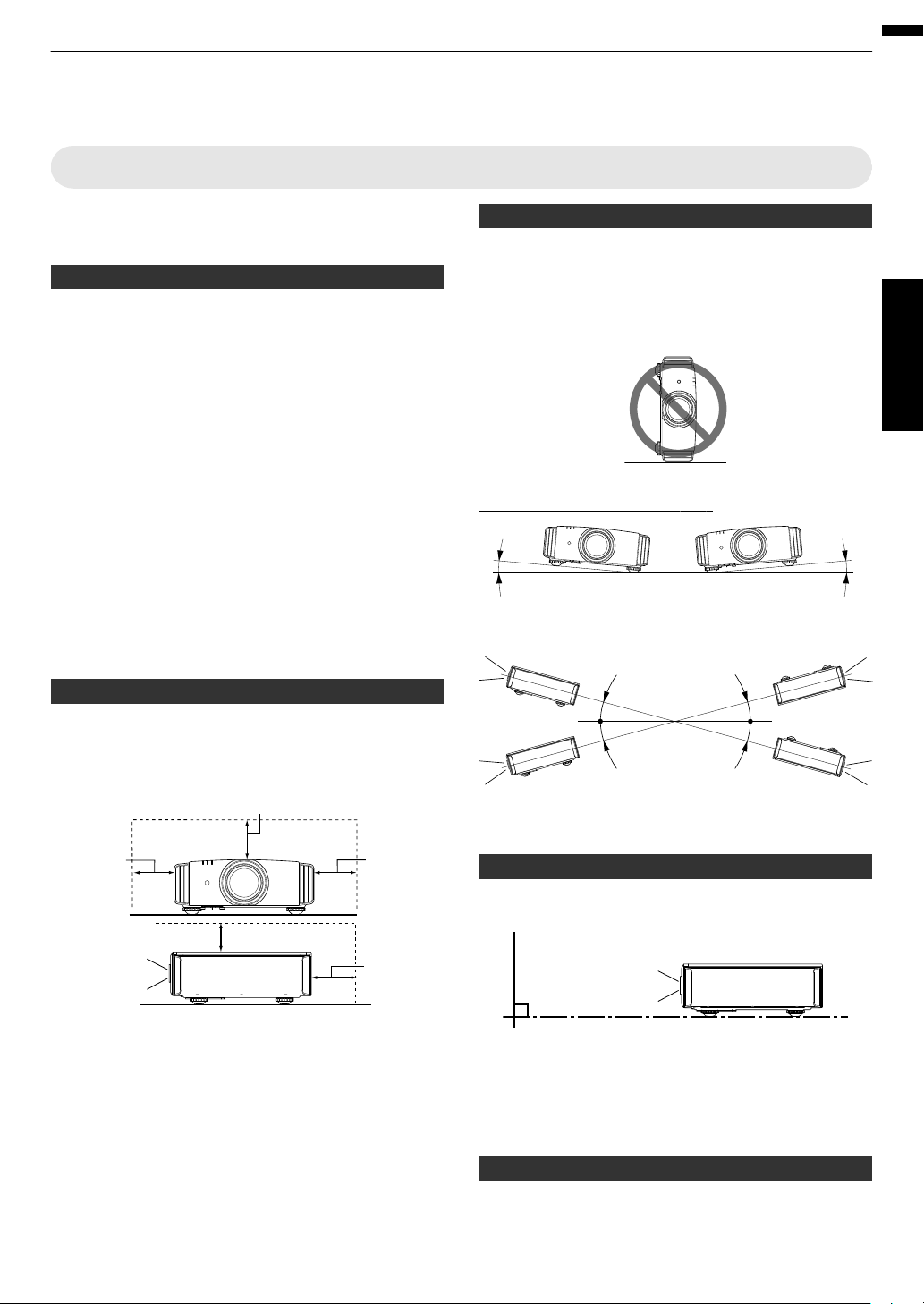
To allow better heat dissipation, keep a clearance between
this unit and its surrounding as shown below. When this unit
is enclosed in a space of dimensions as shown below, use
an air-conditioner so that the internal and external
temperatures are the same. Overheating can cause
damage.
-
-
-
-
-
-
-
-
-
-
-
-
a)
b)
c)
d)
e)
f)
When the power supply cord or plug is damaged.
If liquid has been spilled, or objects have fallen on the
product.
If the product has been exposed to rain or water.
If the product does not operate normally by following the
operating instructions. Adjust only those controls that
are covered by the Operation Manual, as an improper
adjustment of controls may result in damage and will
often require extensive work by a qualified technician to
restore the product to normal operation.
If the product has been dropped or damaged in any
way.
When the product exhibits a distinct change in
performance, this indicates a need for service.
When replacement parts are required, be sure the service
technician has used replacement parts specified by the
manufacturer or with same characteristics as the original
part. Unauthorized substitutions may result in fire, electric
shock, or other hazards.
Upon completion of any service or repairs to this product,
ask the service technician to perform safety checks to
determine that the product is in proper operating condition.
The product should be placed more than one foot away
from heat sources such as radiators, heat registers, stoves,
and other products (including amplifiers) that produce heat.
When connecting other products such as VCR’s, and DVD
players, you should turn off the power of this product for
protection against electric shock.
Power source indicated on the label. If you are not sure of
the type of power supply to your home, consult your
product dealer or local power company.
This product is equipped with a three-wire plug. This plug
will fit only into a grounded power outlet. If you are unable
to insert the plug into the outlet, contact your electrician to
install the proper outlet. Do not defeat the safety purpose of
the grounded plug.
Power-supply cords should be routed so that they are not
likely to be walked on or pinched by items placed upon or
against them. Pay particular attention to cords at doors,
plugs, receptacles, and the point where they exit from the
product.
For added protection of this product during a lightning
storm, or when it is left unattended and unused for long
periods of time, unplug it from the wall outlet and
disconnect the cable system. This will prevent damage to
the product due to lightning and power line surges.
Do not overload wall outlets, extension cords, or
convenience receptacles on other equipment as this can
result in a risk of fire or electric shock.
Never push objects of any kind into this product through
openings as they may touch dangerous voltage points or
short out parts that could result in a fire or electric shock.
Never spill liquid of any kind on the product.
Do not attempt to service this product yourself as opening
or removing covers may expose you to dangerous voltages
and other hazards. Refer all service to qualified service
personnel.
Unplug this product from the wall outlet and refer service to
qualified service personnel under the following conditions:
Getting Started
.
3
Page 4

-
-
-
-
-
-
-
-
-
-
-
Do not place combustibles behind the cooling fan. For
example, cloth, paper, matches, aerosol cans or gas
lighters that present special hazards when over heated.
Do not look into the projection lens while the illumination
lamp is turned on. Exposure of your eyes to the strong light
can result in impaired eyesight.
Do not look into the inside of this unit through vents
(ventilation holes), etc. Do not look at the illumination lamp
directly by opening the cabinet while the illumination lamp is
turned on. The illumination lamp also contains ultraviolet
rays and the light is so powerful that your eyesight can be
impaired.
Do not drop, hit, or damage the light-source lamp (lamp
unit) in any way. It may cause the light-source lamp to
break and lead to injuries. Do not use a damaged light
source lamp. If the light-source lamp is broken, ask your
dealer to repair it. Fragments from a broken light-source
lamp may cause injuries.
The light-source lamp used in this projector is a high
pressure mercury lamp. Be careful when disposing of the
light-source lamp. If anything is unclear, please consult
your dealer.
Do not ceiling-mount the projector to a place which tends to
vibrate; otherwise, the attaching fixture of the projector
could be broken by the vibration, possibly causing it to fall
or overturn, which could lead to personal injury.
Use only the accessory cord designed for this product to
prevent shock.
For health reasons, please take a break of about 5-15
minutes every 30-60 minutes and let your eyes rest. Please
refrain from watching any 3D-images when you feel tired,
unwell or if you feel any other discomfort. Moreover, in case
you see a double image, please adjust the equipment and
software for proper display. Please stop using the unit if the
double image is still visible after adjustment.
Once every three years, please perform an internal test.
This unit is provided with replacement parts needed to
maintain its function (such as cooling fans). Estimated
replacement time of parts can vary greatly depending on
frequency of use and the respective environment. For
replacement, please consult your dealer, or the nearest
authorized JVC service center.
When fixing the unit to the ceiling, Please note that we do
not take any responsibility, even during the warranty period,
if the product is damaged due to use of metal fixtures used
for fixation to the ceiling other than our own or if the
installation environment of said metal fixtures is not
appropriate. If the unit is suspended from the ceiling during
use, please be careful in regard to the ambient temperature
of the unit. If you use a central heating, the temperature
close to the ceiling will be higher than normally expected.
Video images can burn into the electronic com ponent
parts. Please do not display screens with still images of
high brightness or high contrast, such as found in video
games and computer programs. Over a long period of time
it might stick to the picture element. There is no problem
with the playback of moving images, e.g. normal video
footage.
-
-
-
-
-
-
-
Video images can burn into the electronic com ponent
parts. Please do not display screens with still images of
high brightness or high contrast, such as found in video
games and computer programs. Over a long period of time
it might stick to the picture element. There is no problem
with the playback of moving images, e.g. normal video
footage.
Not using the unit for a long time can lead to malfunction.
Please power it on and let it run occasionally. Please avoid
using the unit in a room where cigarettes are smoked. It is
impos sible to clean optical component parts if they are
contaminated by nicotine or tar. This might lead to
performance degradation.
Please watch from a distance three times the height of the
projected image size. Persons with photosensitivity, any
kind of heart disease, or weak health should not use 3D
glasses.
Watching 3D-images might be cause of illness. If you feel
any change in your physical condition, please stop
watching immediately and consult a physician if necessary.
When watching 3D images, it is recommended to take
regular breaks. As the length and frequency of the required
breaks differ for every person, please judge according to
your own condition.
If your child watches while wearing 3D glasses, it should be
accompanied by its parents or an adult guardian. The adult
guardian should be careful to avoid situations where the
child’s eyes might become tired, as responses to tiredness
and discomfort, etc., are hard to detect, and it is possible
for the physical condition to deteriorate very quickly. As the
visual sense is not yet fully developed in children under the
age of 6, please consult a physician in regard to any
problem concerning 3D-images if necessary.
Note that when using the 3D feature, the video output may
appear different from the original video image due to image
conversion on the device.
* DO NOT allow any unqualified person to
install the unit.
Be sure to ask your dealer to install the unit
(e.g.attaching it to the ceiling) since special
technical knowledge and skills are required for
installation. If installation is performed by an
unqualified person, it may cause personal injury or
electrical shock.
Getting Started
.
4
Page 5
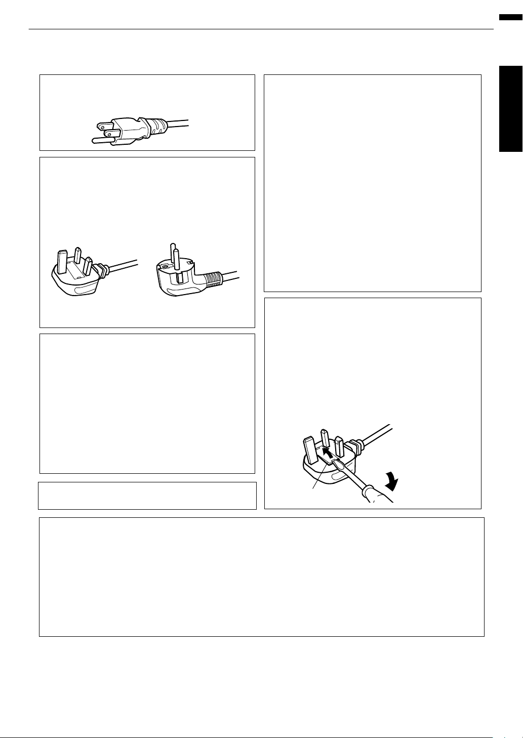
Power cord
Power cord
For European continent
countries
For United Kingdom
Green-and-yellow
Blue
Brown
Fuse
: Earth
: Neutral
: Live
POWER CONNECTION
WARNING:
WARNING:
Do not cut off the main plug from this
equipment.
The power supply voltage rating of this product is
AC110V – AC240V. Use only the power cord
designated by our dealer to ensure Safety and EMC.
Ensure that the power cable used for the projector is
the correct type for the AC outlet in your country.
Consult your product dealer.
If the plug fitted is not suitable for the power points
in your home or the cable is too short to reach a
power point, then obtain an appropriate safety
approved extension lead or adapter or consult your
dealer. If nonetheless the mains plug is cut off,
dispose of the plug immediately, to avoid a possible
shock hazard by inadvertent connection to the main
supply. If a new main plug has to be fitted, then
follow the instruction given below.
Dear Customer,
This apparatus is in conformance with the valid European directives and standards regarding
electromagnetic compatibility and electrical safety.
European representative of JVC KENWOOD Corporation is:
JVC Technical Services Europe GmbH
Konrad-Adenauer-Allee 1-11
61118 Bad Vilbel
Germany
THIS APPARATUS MUST BE EARTHED.
IMPORTANT (Europe only):
The wires in the mains lead on this product are
colored Vert et jaune in accordance with the
following cord:
IMPORTANT (Europe only):
POWER CONNECTION
(United Kingdom only)
When replacing the fuse, be sure to use only a
correctly rated approved type, re-fit the fuse cover.
IF IN DOUBT —— CONSULT A COMPETENT
ELECTRICIAN.
Open the fuse compartment with the blade
screwdriver, and replace the fuse.
(* An example is shown in the illustration below.)
As these colors may not correspond with the
colored making identifying the terminals in your
plug, proceed as follows:
The wire which is colored green-and-yellow must be
connected to the terminal which is marked M with
the letter E or the safety earth or colored green or
green-and-yellow. The wire which is colored blue
must be connected to the terminal which is marked
with the letter N or colored black.
The wire which is colored brown must be connected
to the terminal which is marked with the letter L or
colored red.
For USA and Canada only
Use only the following power cord.
Getting Started
.
5
Page 6
ENGLISH
Information for Users on Disposal of Old Equipment and Batteries
[European Union only]
These symbols indicate that equipment with these symbols should not be disposed
of as general household waste. If you want to dispose of the product or battery,
please consider the collection systems or facilities for appropriate recycling.
Notice: The sign Pb below the symbol for batteries indicates that this battery
contains lead.
Benutzerinformationen zur Entsorgung alter Geräte und Batterien
[Nur Europäische Union]
Diese Symbole zeigen an, dass derartig gekennzeichnete Geräte nicht als normaler
Haushaltsabfall entsorgt werden dürfen. Wenden Sie sich zur Entsorgung des
Produkts oder der Batterie an die hierfür vorgesehenen Sammelstellen oder
Einrichtungen, damit eine fachgerechte Wiederverwertung möglich ist.
Hinweis:
Notification:
Das Zeichen Pb unterhalb des Batteriesymbols gibt an, dass diese
Batterie Blei enthält.
Informations relatives à l’élimination des appareils et des piles usagés, à l’intention
des utilisateurs
[Union européenne seulement]
Si ces symboles figurent sur les produits, cela signifie qu’ils ne doivent pas être
jetés comme déchets ménagers. Si vous voulez jeter ce produit ou cette pile,
veuillez considérer le système de collecte des déchets ou les centres de
recyclage appropriés.
La symbole Pb en dessous du symbole des piles indique que cette
pile contient du plomb.
Informatie voor gebruikers over het verwijderen van oude apparatuur en batterijen
[Alleen Europese Unie]
Deze symbolen geven aan dat appara tuur met dit symbool niet mag worden
weggegooid als algemeen huishoudelijk afval. Als u het product of de batterij wilt
weggooien, kun t u inzamelsystemen of faciliteiten voor een geschikte recycling
gebruiken.
Opmerking: Het teken Pb onder het batterijsymboo l geeft aan dat deze batterij
lood bevat.
Battery
Batterie
Pile
Batterij
Products
Produkte
Produits
Producten
DEUTSCH
FRANÇAIS
NEDERLANDS
Información para los usuarios sobre la eliminación de baterías/pilas usadas
[Sólo Unión Europea]
Estos símbolos indican que el equipo con estos símbolos no debe desecharse
con la basura doméstica. Si desea desechar el producto o batería/pila, acuda
a los sistemas o centros de recogida para que los reciclen debidamente.
Atención: La indicación Pb debajo del símbolo de batería/pila indica que ésta
contiene plomo.
Baterías/pilas
Productos
ESPAÑOL / CASTELLANO
Getting Started
.
6
Page 7
ITALIANO
Informazioni per gli utenti sullo smaltimento delle apparecchiature e batterie obsolete
[Solo per l’Unione Europea]
Questi simboli indicano che le apparecchiature a cui sono relativi non devono
essere smaltite tra i rifiuti domestici generici. Se si desidera smaltire questo
prodotto o questa batteria, prendere in considerazione i sistem i o le strutture di
raccolta appropriati per il riciclaggio corretto.
Nota: Il simbolo Pb sotto il simbolo delle batter ie indica che questa batteria contiene
piombo.
Informação para os utilizadores acerca da eliminação de equipamento usado e pilhas
[Apenas União Europeia]
Estes símbolos indicam que o equipamento com estes símbolos não deve ser
eliminado juntamente com o restante lixo doméstico. Se p retende eliminar
o produto ou a pilha, utilize os sistemas de recolha ou instalações para uma
reciclagem apropriada.
Aviso:
Σημείωση:
O sinal Pb abaixo do símbolo para pilhas indica que esta pilha contém
chumbo.
Πληροφορίες για την απόρριψη παλαιού εξοπλισμού και μπαταριών
[ Ευρωπαϊκή Ένωση μόνο ]
Αυτά τα σύμβολα υποδηλώνουν ότι ο εξοπλισμός που τα φέρει δεν θα πρέπει
να απορριφθεί ως κοινό οικιακό απόρριμμα . Εάν επιθυμείτε την απόρριψη
αυτού του προϊόντος ή αυτής της μπαταρίας , χρησιμοποιήστε το σύστημα
περισυλλογής ή εγκαταστάσεις για ανάλογη ανακύκλωση .
Το σύμβολο Pb κάτω από το σύμβολο μπαταρίας υποδηλώνει ότι
η μπαταρία περιέχει μόλυβδο .
Brugerinformation om bortskaffelse af gammelt udstyr og batterier
[Kun EU]
Disse symboler angiver, at udstyr med disse symboler ikke må bortskaffes som
almindeligt husholdningsaffald. Hvis du ønsker at smide dette produkt eller batteri
ud, bedes du overveje at bruge indsamlingssystem et eller steder, hvor der kan
ske korrekt gen brug.
Bemærk: Tegnet Pb under symbolet for batterierne angiver, at dette batteri
indeholder bly.
Batteria
Pilha
Μπαταρία
Batteri
Prodotti
Produtos
Προϊόντα
Produkter
PORTUGUÊS
ΕΛΛΗΝΙΚΑ
DANSK
Tietoja vanhojen laitteiden ja akkujen hävittämisestä
[Vain Euroopan unioni]
Nämä symbolit ilmaisevat, että symboleilla merk ittyä laitetta ei tulisi hävittää
tavallisen kotitalousjätteen mukana. Jos haluat hävit tää tuotteen tai sen akun,
tee se hyödyntämällä akkujen keräyspisteitä tai muita kier rätyspaikkoja.
Huomautus: Akkusymbolin alapuolella oleva Pb-merk intä tarkoit taa, että akku
sisältää lyijyä.
Akku
Tuotteet
SUOMI
Getting Started
.
7
Page 8
SVENSKA
Information för användare gällande bortskaffning av gammal utrustning och batterier
[Endast den Europeiska unionen]
Dessa symboler indikerar att utrustning med dessa symboler inte ska hanteras
som vanligt hushållsavfall. Om du vill bortsk affa produkten eller batteriet ska du
använda uppsamlingssystem eller inrättningar för lämplig återvinning.
Observera: Märkningen Pb under symbolen för batterier indikerar att detta batteri
innehåller bly.
Opplysninger til brukere om kassering av gammelt utstyr og batterier
[Bare EU]
Disse symbolene viser at utstyr med dette symbolet, ikke skal kastes sammen
med vanlig husholdningsavfall. Hvis du vil kass ere dette produkte t eller batteriet,
skal du vurdere å bruke innsam lingssystemene eller andre muligheter for riktig
gjenbruk.
Merk:
Уведомление:
Tegnet Pb under symbolet for batterie r, viser at batteriet inneholder bly.
Сведения для пользователей по утилизации старого оборудования и батарей
[только для Европейского союза]
Данные символы указывают на то, что оборудование, на которое они
нанесены, не должны утилизироваться, как обычные бытовые отходы. При
необходимости утилизировать такое изделие или батарею обратитесь в
специальный пункт сбора для их надлежащей переработки.
Надпись Pb под символом батар ей указывает на то, что
данная батарея содержит свинец.
Informace pro uživatele k likvid aci starého zařízení a baterií
[Pouze Evropská unie]
Tyto symboly označují, že produkty s těmito symboly se nesmí likvidovat jako
běžný odpad. Pokud chcete produkt nebo baterii zlikvidovat, využijte sběrný
systém nebo jiné zařízení, které zaji stí řádnou recyklaci.
Bemærk: Značka Pb pod symbolem pro ba te rie znamená, že tato baterie
obsahuje olovo.
Batteri
Batteri
Батарея
Baterie
Produkter
Produkter
Изделия
Produkty
NORSK
Informacje dla użytkowników dotyczące poz bywania się zużytego sprzętu i baterii
[Tylko kraje Unii Europejskiej]
Te symbole oznaczają, że sprzę tu nie należy wyr zucać razem z odpadami
gospodarczymi. Jeśli trzeba po zbyć się tego produktu lub ba terii, proszę
skorzystać z systemu odbioru lub urządzeń do zbió rki odpadów elektronicznych,
w celu odpowiedniego ponowne go ich przetworzenia.
Uwaga: Oznaczenie Pb, znajdujące się pod symbole m baterii wskazuje, że ta
bateria zawiera ołów.
Bateria
Produkty
POLSKI
Getting Started
.
8
Page 9
MAGYAR
Felhasználói információ az elhasznált be rendezések és akkumulátorok elhelyezéséről
[Csak az Európai Unióban]
Ez a szimbólum azt jelzi, hogy a berendezés nem helyezhető az általános
háztartási hulladék közé. Ha meg szeretne szabadulni a terméktől vagy az
akkumulátortól, akkor legyen tekintettel az gyűjtő rendszerre vagy intézményekre
a megfelelő hasznosítás érdekében.
Megjegyzés: Az alábbi Pb szimbólum - ha az akkum ulátoron megtalálható - azt
jelzi, hogy az akkumulátor ólmot tartalmaz.
Informacije za korisnike o odlaganju stare opreme i baterija
[Samo u zemljama gde se primenjuje]
Ovi simboli ukazuju da proizvod i baterije sa ovim simbolom ne smeju biti odloženi
kao nesortiran kućni otpad. Ako želite da ih se rešite, molimo vas da ne
upotrebljavate običnu kantu za đubre. Postoje zasebni sistemi za prikupljanje
ovakvih proizvoda.
Naznaka: Hemijski simbol Pb ispod simbola za baterije ukazuje na to da li baterija
sadrži olovo.
Akkumulátor
Baterija
Termékek
Produkt
Cрпска
Getting Started
.
9
Page 10

Contents
Getting Started
Getting Started
Safety Precautions .................................................. 2
Accessories/Optional Accessories ........................ 11
Check the Accessories ......................................
Optional Accessories ......................................... 11
Main Features ....................................................... 12
Controls and Features ........................................... 14
Main Unit - Front ................................................ 14
Main Unit - Bottom ............................................. 14
Main Unit - Rear ................................................. 15
Main Unit - Input Terminals ................................ 16
Remote Control ................................................. 17
Loading Batteries into the Remote Control ........ 18
Effective Range of Remote Control Unit ............ 18
Set up
Installing the Projector ........................................... 19
Precautions during Installation ........................... 19
Precautions during Mounting ............................. 20
Adjusting the Position ........................................ 21
Connecting the Projector ....................................... 22
Connecting to the HDMI Input Terminal (Digital
Input) ................................................................. 22
Connecting to the LAN Terminal ........................ 23
Connecting to the RS-232C Terminal ................ 23
Connecting to the TRIGGER Terminal ............... 24
Connecting the Power Cord (Supplied Accessory)
Operate
Viewing Videos ...................................................... 25
Adjusting the Projector Screen .............................. 27
Adjusting the Lens According to the Projection
Position .............................................................. 27
Saving and Retrieving Adjustment Settings ....... 28
Adjusting Image Quality Automatically According to
the Viewing Environment ................................... 30
Adjusting the Screen Size (Aspect) ................... 31
Viewing 3D Movies ................................................ 32
Installing the 3D SYNCHRO EMITTER .............. 32
Viewing 3D Movies ............................................ 33
Converting 2D Movies to 3D Movies for Viewing
Adjusting 3D Movies .......................................... 34
Adjust/Set
Selecting an Image Quality According to the Video
Type ...................................................................... 35
Setting the Picture Mode ................................... 35
Setting the Color Profile ..................................... 36
11
...... 24
....... 34
Adjusting to the Preferred Color (Color
Management)
Adjusting Movies for Increased Expressiveness
(Multiple Pixel Control) .......................................... 39
Fine-tuning the Image Quality ............................... 41
Adjusting the Output Value of the Projected Image
(Gamma) ........................................................... 41
Fine-tuning to the Preferred Gamma Setting ..... 42
Reducing the After-image of Fast-moving Images
(Clear Motion Drive (C.M.D.)) ............................ 44
Viewing High Contrast Images (Lens Aperture) . 44
Adjustments and Settings in the Menu .................. 45
List of Menu Items ............................................. 45
Picture Adjust .................................................... 47
Input Signal ........................................................ 50
Installation ......................................................... 52
Display Setup .................................................... 58
Function ............................................................. 59
Information ......................................................... 60
.................................................... 38
Maintenance
Replacing the Lamp .............................................. 61
Lamp Replacement Procedure .......................... 61
Resetting the Lamp Time ................................... 63
Maintaining the Cabinet and Remote Control ........ 63
Cleaning and Replacing the Filter ......................... 64
Troubleshooting
Troubleshooting .................................................... 65
When the following messages appear... ................ 69
Others
External Control .................................................... 70
RS-232C Specifications ..................................... 70
TCP/IP Connection ............................................ 70
Command Format .............................................. 71
Remote Control Code ........................................ 72
Communications Example ................................. 73
Specifications ........................................................ 74
Index ..................................................................... 81
Symbols used in this manual
S
indicates a function that is supported by DLA-X900R.
R
indicates a function that is supported by DLA-X700R.
Q
indicates a function that is supported by DLA-X500R.
Items not marked with any of the above symbols are
supported by all models.
10
Page 11
Accessories/Optional Accessories
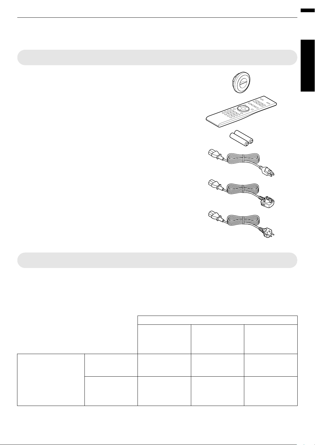
Check the Accessories
Lens cover Q .................................................................... 1 piece
* It is attached to the main unit at the time of shipment.
Remote control ....................................................................... 1 piece
.
.
Getting Started
AAA-size batteries (for operational check) ............................ 2 pieces
Power cord (for USA) (about. 2 m) ......................................... 1 piece
.
Power cord (for UK) (about. 2 m) ............................................ 1 piece
.
Power cord (for EU) (about. 2 m) ............................................ 1 piece
.
0
INSTRUCTIONS (this book), warranty card, and other printed material are also included.
Optional Accessories
0
Replacement lamp model: PK-L2312U
0
3D GLASSES: model PK-AG3
0
3D SYNCHRO EMITTER: model PK-EM2
Compatibility Chart for 3D SYNCHRO EMITTER and 3D GLASSES
.
3D SYNCHRO EMITTER PK-EM1 *
(Communication
Method:
IR
(Infrared))
PK-EM2
(Communication
Method: RF (Radio
frequency))
* Discontinued product
Please check with your authorized dealer for details.
PK-AG1 *
(Communication
Method: IR (Infrared))
X X —
— — X
3D GLASSES
PK-AG2 *
(Communication
Method: IR (Infrared))
PK-AG3
(Communication
Method: RF (Radio
frequency))
11
Page 12
Main Features
The photos are for illustrative purposes only.
The photos are for illustrative
purposes only.
The photos are for illustrative purposes only.
Getting Started
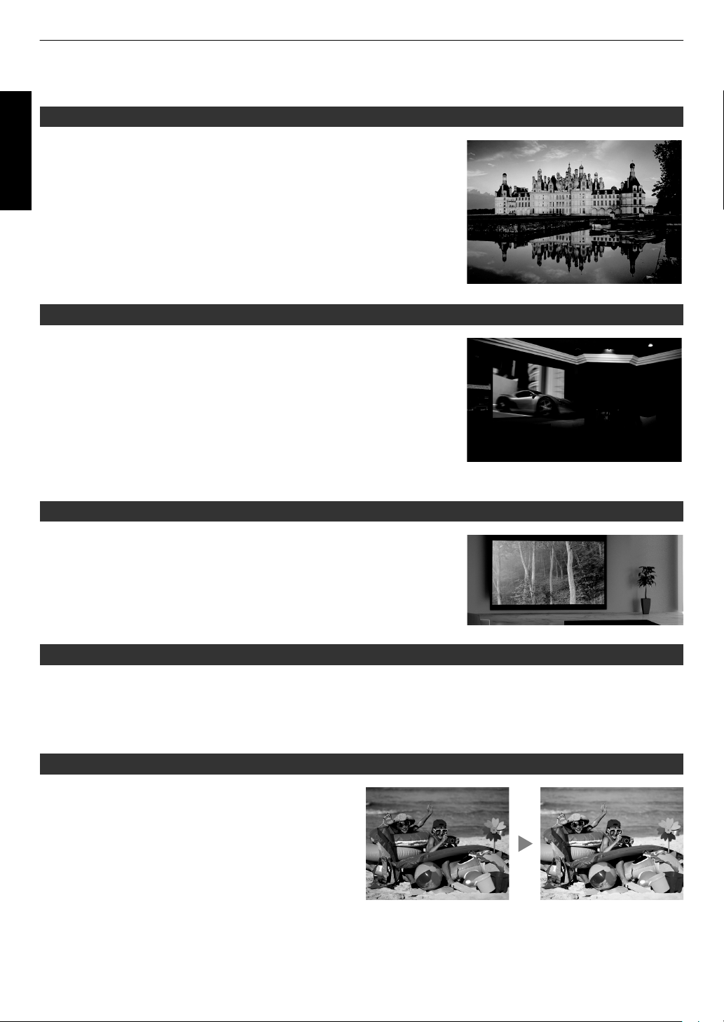
New, impressive image quality with the 4K resolution
By employing JVC’s unique image-processing technology (MPC), focus and
blurring can be detected and adjusted in real time, allowing viewers to enjoy
the enhanced expressiveness of 4K images. (p. 39)
3D video expressions with a highly realistic feel
With the 3D feature, you can enjoy 3D movies with a more realistic effect.
(p. 32)
With the 2D-3D conversion feature, you can now enjoy 3D movies by
converting
video camera into 3D ones. (p. 34)
2D videos of TV
programs or those that are recorded using a home
Optimal image quality adjustment according to the viewing environment
Halation that occurs in environments such as a living room with white walls is
taken into consideration for optimal viewing. (p. 30)
0
You can
finer adjustments.
For more details, please refer to our website.
http://www3.jvckenwood.com/projector/support/index.html
utilize the optional
optical sensor and dedicated software to make
Flexible installation
In addition to the 2x motorized zoom & focus lens, the wide coverage of the lens shift functions also makes installation
of the projector more flexible. (p. 27)
The lens memory feature,
to different video size formats easily.
which enables focus, zoom, or shift settings to be saved or retrieved, enables you to switch
Customizable image quality adjustment feature
You can make adjustments according to the type of video
images or your preferences to enjoy the videos in optimal
quality. (p. 35)
The Real Color Imaging Technology (a color reproduction
technology developed by JVC)
image quality that is closer to the original image. (p. 36)
enables reproduction in an
12
Page 13
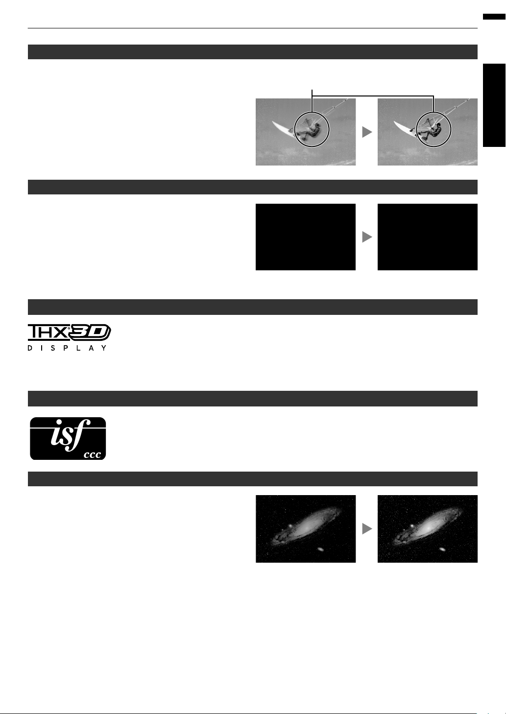
Clear video expression with little after-image (C.M.D.)
Sharp depiction of details with minimal blur
The photos are for illustrative purposes only.
ABCD
After adjustmentBefore adjustment
The photos are for illustrative purposes only.
ABCD
ABCD
ABCD
®
After adjustmentBefore adjustment
The photos are for illustrative purposes only.
Optimal interpolation according to the content is made
possible with the new high-definition image interpolation
technique that supports 3D images.
Viewers can enjoy clear video expression with little afterimage. (p. 44)
* C.M.D. is the abbreviation for Clear Motion Drive.
High-precision pixel adjustment feature
With the highly-precise “Pixel Adjust” feature, you can
enjoy a clear video quality with little color fringing
throughout the entire image.
(p. 53)
* Equipped
separately when an anamorphic lens is used and when
you are using the projector with a screen.
THX certification S R
THX
The
cleared more than 400 image quality tests.
with two memories, you
For S R, a “THX 3D Display Certification” by THX has been obtained.
In addition to 2D movies, you can also enjoy faithful reproduction of images in a “quality as
intended by the filmmaker” during playback of 3D movies.
certification
3D
“an indication of high definition and high resolution”, which is granted to products that have
is
can save the settings
Getting Started
isf certification S R
S R are isf-certified, so calibration can be performed by an isf-certified trainer.
After calibration is performed, an isf mode is added to the Picture mode.
For more details, please refer to the isf website.
http://www.imagingscience.com/
Intelligent Lens Aperture
JVC has developed an image analysis algorithm, which
analyzes the state of the video image in real time, and
controls the aperture dynamically according to the image
information.
This technology enables viewers to enjoy video images
with enhanced contrast.
13
Page 14
Controls and Features
ABC
D
E
E
FG
H
Getting Started
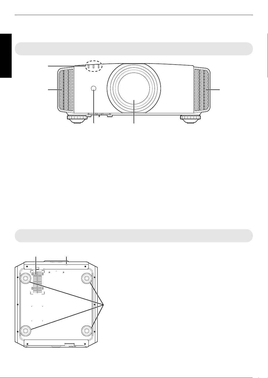
Main Unit - Front
.
A
Lens
This is a projection lens. Do not look through the lens
while an image is projected.
B
Lens cover S R
The lens cover opens/closes when the power supply
is turned on/off. (p. 52)
0
For Q, attach the lens cover when the unit is not
in use.
C
Remote Sensor (front)
Please aim
it.
* There is also a remote sensor at the rear.
the remote control
at this area when using
Main Unit - Bottom
D
Indicator
Refer to “Indicator Display on the Main Unit”p.
E
Exhaust vent
Warm air is discharged to cool down the internal
temperature.
Do not block the vents.
F
Inlets (at 3 points on the rear/bottom)
The inlets take in air to cool down the internal temperature.
Do not block or prevent the outflow of hot air. Doing so may cause
the unit to malfunction.
* There
G
H
are two inlets on
Manual button for lens cover S R
The lens cover can be opened when pressed down.
It is used for maintenance purposes. You can also make use of it
when you need to open the lens cover urgently.
Feet
The height and angle of the projector can be adjusted by turning the
foot. (0 to 5 mm) (p. 21)
When the foot is removed, it can be used as the mounting holes for
the ceiling mount bracket.
the right and left sides at the rear of the unit.
78.
14
Page 15
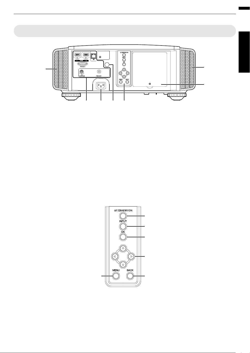
Main Unit - Rear
F
IKLM
F
J
[MENU]: Displays the menu
[BACK]: Returns to the previous menu
[JKH I] keys: Selects an item
[OK]: Confirms a selection
[INPUT]: Switches the input
A [STANDBY/ON]: Turns “on”/“off” the
power
.
Getting Started
I
Input terminals
In addition to the video input terminal, there are also
other connection terminals for devices such as
controllers and optional equipment.
Please see
more details about the terminals.
J
Lamp cover
When replacing the light source lamp, remove this
cover.
K
Operation panel
For more details, please refer to the
panel” in the diagram below.
“Main Unit - Input Terminals”p.
16
“Operation
Operation panel
for
L
Remote Sensor (rear)
the remote control at this area when using
aim
Please
it.
* There is also a remote sensor at the front.
M
Power input terminal
Connect the supplied power cord to this terminal.
.
15
Page 16
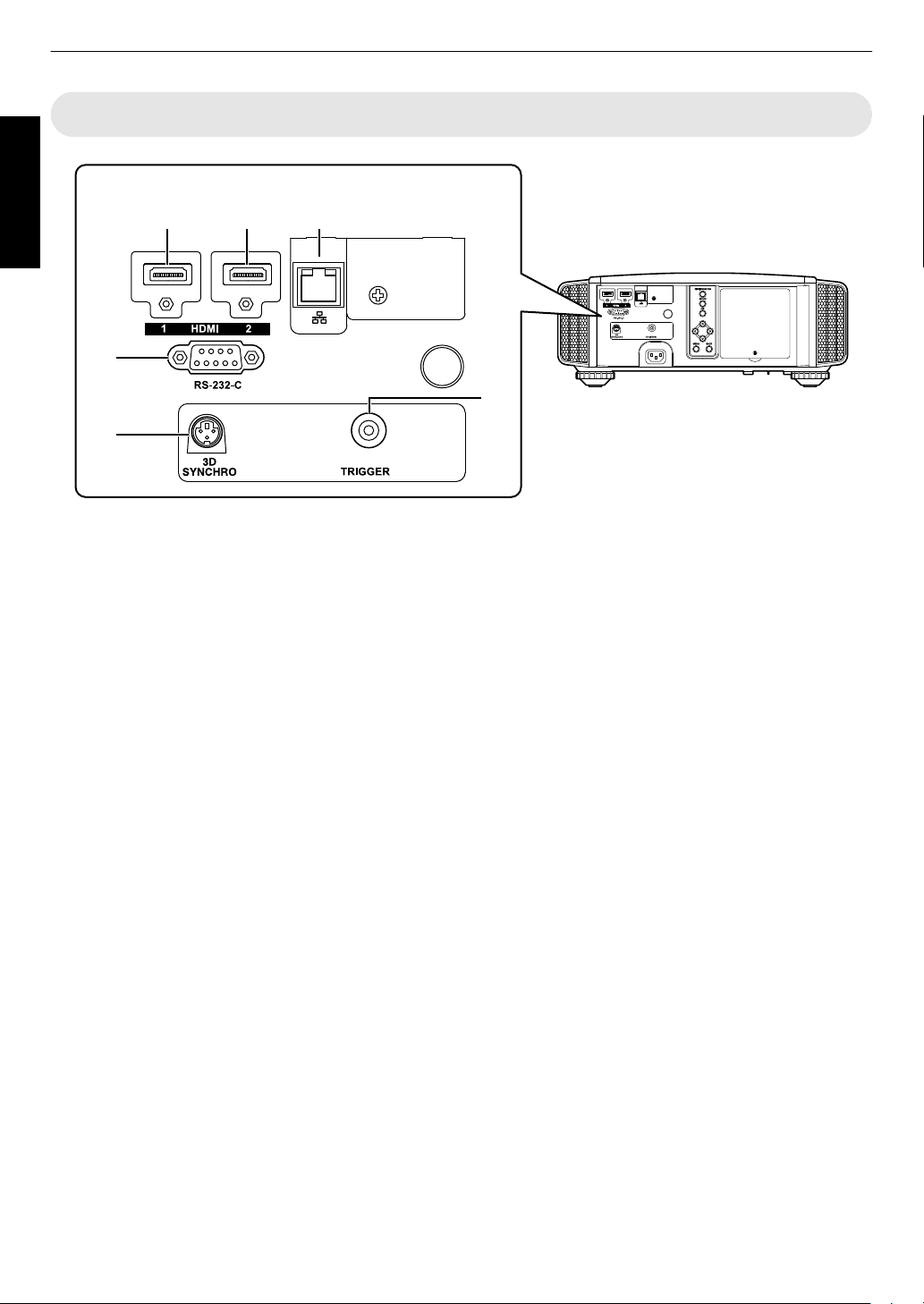
Main Unit - Input Terminals
A B C
D
E
F
Enlarged View of Rear Face
Getting Started
.
A
[HDMI 1] input terminal
B
[HDMI 2] input terminal
For connecting to devices that support HDMI output.
(p. 22)
It is fitted to the M3 lock hole. The depth of the screw
hole is 3 mm.
C
[LAN] terminal (RJ-45)
The projector can be controlled by connecting it to a
PC through the computer network for control
commands to be sent to the projector.
D
[RS-232C] terminal (D-sub 9-pin
male)
The projector can be
this terminal.
E
[3D SYNCHRO] terminal
By connecting a 3D SYNCHRO EMITTER (sold
separately) to this terminal, you can view 3D movies.
controlled by connecting a PC to
F
[TRIGGER] terminal (E)
terminal for DC 12 V, 100 mA power supply. It
Output
is used for sending output signals to control devices
such as an elevating screen that is equipped with a
trigger function.
Note that improper connection may damage the
projector. (Tip=DC +12 V, Sleeve=GND)
16
Page 17
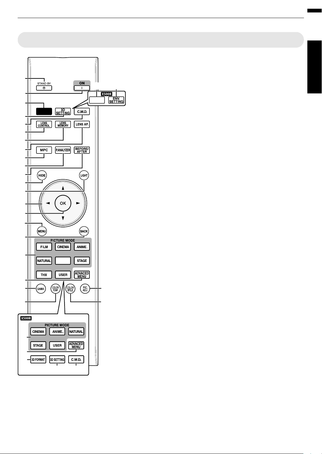
Remote Control
INPUT
PHOTO
A
T
Y
W
G
F
C
D
K
O
M
B
E
H
I
J
L
N
P
Q
R
S
T
X
ED
V
Z
U
U
INFO.
Getting Started
O
[LIGHT]
Illuminates the buttons on the
remote control.
P
[JKH I] keys
For selecting an item.
Q
[OK]
Confirms a selected item.
R
[MENU]
Displays the menu,
or hides the menu if it is
displayed.
S
[BACK]
Returns to the previous menu.
T
[PICTURE MODE]
Switches the Picture mode to
[FILM]*, [CINEMA], [ANIME.],
[NATURAL], [PHOTO]*,
[STAGE], [THX]*, or [USER].
(p. 35)
* S R only
U
[ADVANCED
MENU]
Pressing the button each time
switches the menu in the
following sequence: “Picture
Mode”"“Color
Profile”"“Color
Temp.”"“Gamma”
V
[GAMMA]
For setting the gamma level.
(p. 41)
W
[COLOR TEMP.]
For setting the color
temperature. (p. 48)
X
[3D FORMAT] Q
Switches the 3D format.
(p. 33)
Y
[COLOR P.FILE]
Switches the color profile.
(p. 36)
Z
[PIC. ADJ.]
Switches the items for
adjusting the image quality,
such as contrast, brightness,
etc. (p. 49)
17
A
B [STAND BY]
Turns off the power. (
B
C [ON]
Turns on the power. (p. 25)
C
[INPUT]
Select an input from [HDMI 1]
and [HDMI 2]. (p. 25)
D
[3D SETTING]
Displays the 3D setting menu.
(p. 33)
E
[C.M.D.]
For
setting frame interpolation.
(p. 44)
F
[INFO.] Q
Displays the information
menu. (p. 60)
G
[ENV.SETTING]
p. 26)
Q
Displays the “Environment
Setting” menu, (p. 30)
H
[LENS CONTROL]
For adjusting focus, zoom, and
shift. (p. 27)
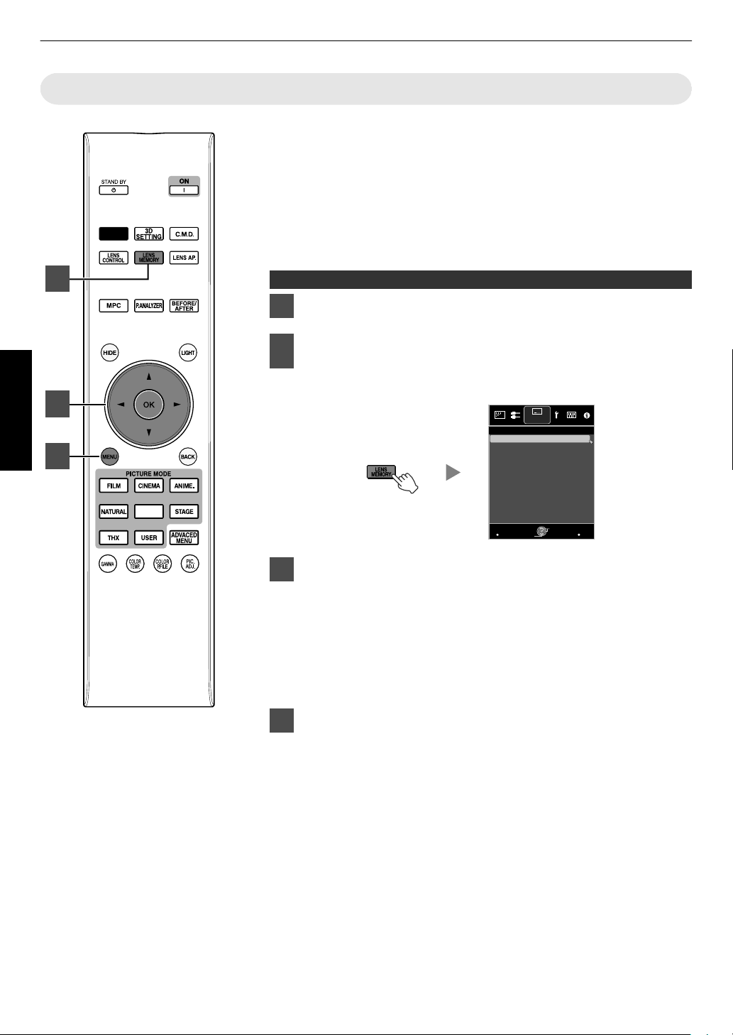
I
[LENS MEMORY]
Switches between saving,
retrieving, and editing of the
lens memory. (p. 28)
J
[LENS AP.]
For setting the lens aperture.
(p. 44)
K
[MPC]
For setting the MPC level.
(p. 39)
L
[P.ANALYZER]
Turns on/off the analysis
screen. (p. 40)
M
[BEFORE/AFTER]
Displays the image before or
after an effect is applied. This
is used for MPC and Color
Management.
(p. 38, p. 39)
N
[HIDE]
Hides the image temporarily.
(p. 25)
Page 18
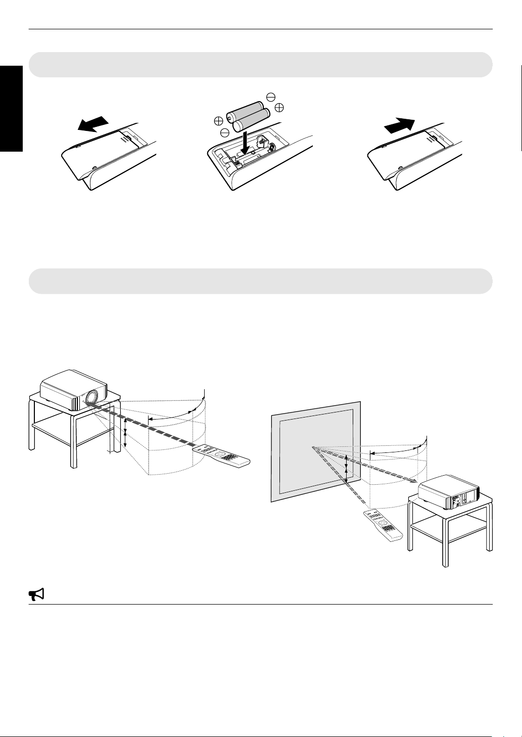
Loading Batteries into the Remote Control
30°
30°
20°
20°
Remote Control
This unit
A
B
30°
30°
20°
20°
20°
20°
20°
20°
Screen
Remote Control
This unit
Getting Started
.
0
If the remote control has
to be brought closer to the projector to operate, it means that the batteries are wearing out.
Replace the batteries with new ones (AAA).
0
Insert the batteries according to the t s marks. Be sure to insert the s end first.
0
If an error occurs while using the remote control, remove the batteries and wait for five minutes. Load the batteries
again and operate the remote control.
Effective Range of Remote Control Unit
When aiming the remote control toward the sensor on this
unit
(front
or
rear),
that the distance to the sensor
ensure
is within 7 m.
If the remote control fails to work properly, move closer
to this unit.
Control through reflection off a screen, etc.
Ensure that the total of distance A (between this unit and
the screen) and distance B (between the remote control
and the screen) is within 7 m.
As the efficiency of signals reflected from the remote
*
control unit varies with the type of screen used, the
operable distance may decrease.
.
.
CAUTION
0
Do not put the remote control in a place with an exposure to direct sun light or high temperature.
It may deformed due to heat, or the internal components may be adversely affected resulting in fire hazard.
0
Remove the batteries from the remote control when storing the remote control.
Storing the remote control for a prolonged period without removing the batteries can cause battery leakage.
18
Page 19
Installing the Projector
Front
150 mm
and above
200 mm
and above
300 mm
and above
300 mm
and above
150 mm and above
5° 5°
15°
15°
15°
15°
Screen
Front
Precautions during Installation
Please read the following carefully before installing this
unit.
Do not install at the following
This unit is a precision device. Please refrain from
installing or using it at
the following locations. Otherwise,
it may cause fire or malfunction.
0
Dusty, wet and humid places
0
Places subject to oily smoke or cigarette smoke
0
On top of a carpet or bedding, or other soft surfaces
0
Places exposed to direct sunlight
0
Places with a high or low temperature
0
Do not install this unit in a room that is oily or subject
cigarette smoke. Even a
to
small quantity of smoke or
oiliness can have a long-term impact on this unit.
* This unit produces a great amount of heat, and is
designed to take in cool air to cool its optical
components. Using the unit at the above locations
may cause dirt to attach to the light path, thereby
resulting in dark images or dull colors.
* Dirt that sticks to the optical components cannot be
removed.
Maintain clearance from the wall, etc.
As the unit discharges a large amount of heat, install it
with adequate clearance from the surroundings as shown
below.
.
Using the projector
This unit uses a projection
in use.
Please refrain from projecting in the following
circumstances. Otherwise, it may cause fire or
malfunction.
0
Projection with the unit stood vertically
0
Projection with the unit inclined at an angle
Horizontal inclination: within ± 5 °
.
Vertical inclination: within ± 15 °
0
Malfunction may occur if the angle is not set within the
abovementioned range.
lamp, which will heat up when
.
.
Set up
Leave the front area of the unit unblocked.
If there is any obstructing object in front of the exhaust
vent, hot air will flow
back to the unit and cause it to heat
up. Hot air flowing out of the unit may cast shadows on
the screen (heat haze phenomenon).
Installing the screen
Install the unit and the screen such that they are
perpendicular to each other.
.
0
Please choose a screen material with non-uniform
patterns.
Uniform
patterns
such
checks may cause
as
interference patterns to occur.
0
In this case, you can
change the size of the screen to
make the interference patterns less noticeable.
Using the projector at a high altitude
When using this unit at a location that is higher than 900
m above sea level (low air pressure), set the “High
Altitude Mode” to “On”. (p. 54)
19
Page 20
Precautions during Mounting
Air Inlets
4 Locations
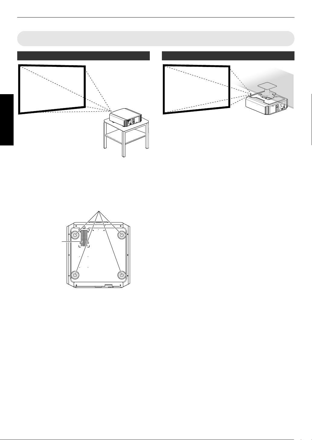
Securing (mounting) the projector
Set up
.
0
When this unit is to
be mounted to a fixed position for
use, install it horizontally.
0
Make sure to secure the main unit to prevent
accidents such as during an earthquake.
Securing with screws
Securing the projector (ceiling mount)
.
0
Be sure to ask your dealer to install the unit for you.
Installing the unit on your own may cause the unit to
fall resulting in injury.
0
Take the necessary actions to prevent the main unit
from falling off such as during an earthquake.
0
Regardless of the warranty period, JVC is not liable
for any product damage caused
with non-JVC ceiling fittings or to an environment that
is not suited for ceiling mount.
0
When using the unit with it suspended from a ceiling,
pay attention to the surrounding temperature. When
a heater is in use, the temperature around the ceiling
may be higher than expected.
0
attach the unit to
To
the ceiling mount bracket, set the
torque between the range of 1.5N m to 2.0N m.
Tightening with torque exceeding the above range
may cause damage to the unit, which may result the
unit to fall.
by mounting the unit
.
Remove the four feet at the bottom, and fasten using the
screws (M5 screws, 13 to 23 mm).
* Using screws other than those
designated may cause
the unit to break down.
* Leave a clearance of at least 10 mm from the bottom
surface of the unit to allow it to take in cool air.
20
Page 21
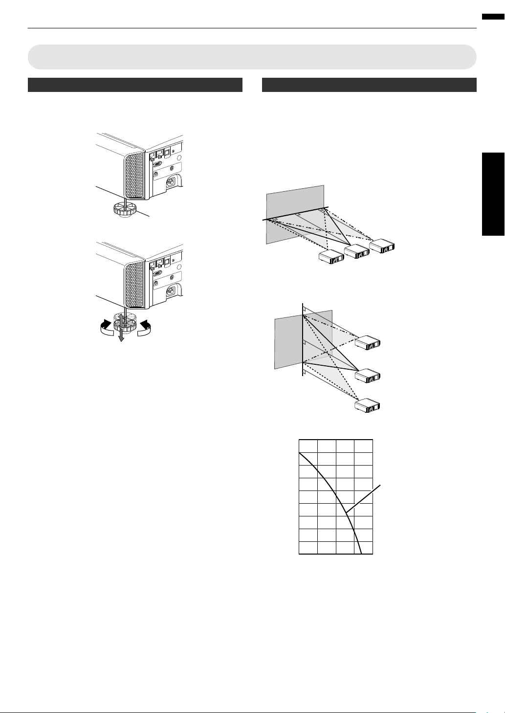
Adjusting the Position
ContractExtend
Feet
90
80
70
60
50
40
30
20
10
0
10 3020 40
Lens movement range
Horizontal lens shift (%)
Vertical lens shift (%)
Lens shift Range
Up to about 80% of the
projected image
Horizontal Position: 0 % (Center)
Vertical Position
Up to about 34% of the
projected image
Vertical Position: 0% (Center)
Horizontal Position
■
■
■
Adjusting the elevation angle of the projector
The height and inclination of the unit (0 to 5 mm) can be
adjusted by turning the feet.
Lift the unit and adjust the four feet.
.
Adjusting the position of the image
By using the lens shift feature of this unit, you can shift
the image upward/downward or to the left/right. Set it to
your preferred position.
Æ “Adjusting the Lens According to the Projection
Position” (p.
27)
Set up
.
0
The maximum vertical shift varies with the amount of
horizontal shift. Similarly, the maximum horizontal
shift also changes with the amount of vertical shift.
0
The
values
on
the
are intended as a guide. Use
graph
them for reference during installation.
21
Page 22
Connecting the Projector
HDMI Output Terminal
BD/DVD Recorder, etc.
Laptop, etc.
HDMI Cable (Sold Separately)
This Unit
To [HDMI 1] or [HDMI 2] input
terminal
HDMI-DVI Conversion Cable (Sold Separately)
To [HDMI 1] or [HDMI 2] input
terminal
This Unit
DVI Output Terminal
Desktop PC, etc.
0
Do not turn on the power until connection is complete.
0
The connection procedures differ according to the device used. For details, please refer to the instruction manual
of the device to be connected.
0
This projector is used for projecting images. To output the audio of connected devices, please connect a separate
audio output device, such as an amplifier or speaker.
0
The images may not be displayed depending on the devices and cables to be connected.
Use only HDMI cables (sold separately) that are HDMI-certified.
0
Some cables cannot be connected to this unit due to the size of their connector cover.
Set up
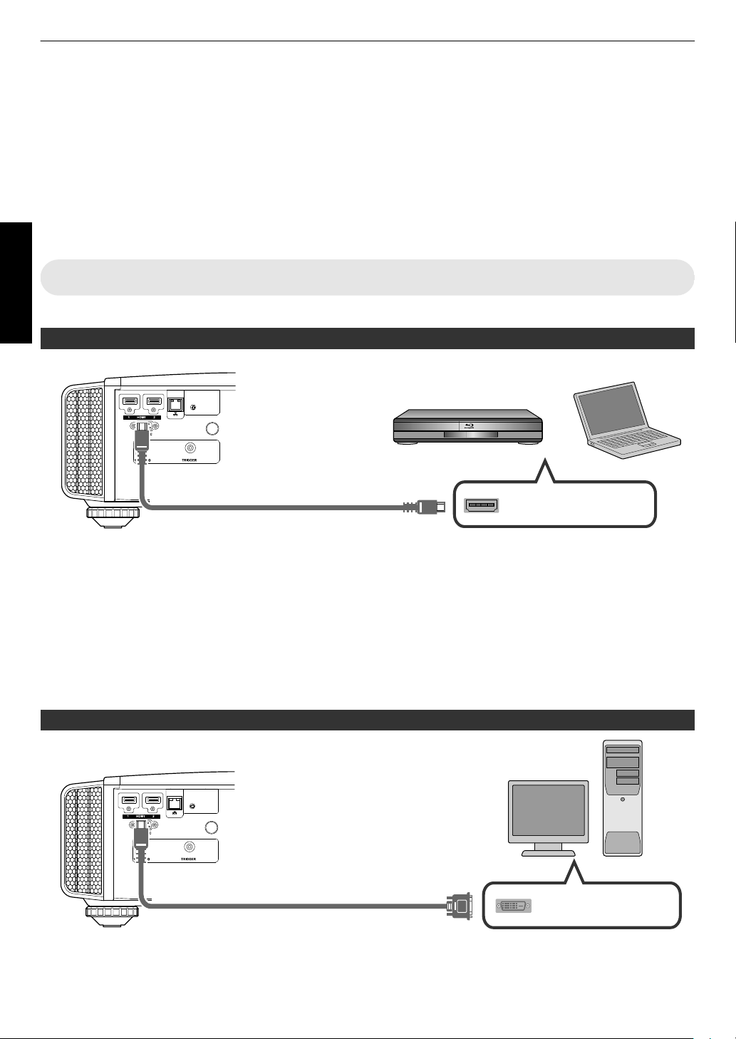
Connecting to the HDMI Input Terminal (Digital Input)
Connecting via HDMI cable
.
0
If noise occurs, move the laptop away from this unit.
0
For a transmission bandwidth in compliance with the HDMI standard, a 340 MHz cable is recommended. When
using a cable with a
bandwidth of 75 MHz, you are recommended to set the resolution of the equipment transmitting
the video to 1080i or lower.
0
If the video is not displayed, try to reduce the length of the cable or lower the resolution of the video transmitting
equipment.
0
the source device is
If
connected to the projector through an intermediate device such as an AV amplifier or divider,
the video image may not appear depending on the specifications of the intermediate device.
In this case, connect the source device directly to the projector, and check whether the video image is displayed.
Connecting via HDMI-DVI conversion cable
.
0
If noise occurs, move the desktop PC away from this unit.
0
If the video is not displayed, try to reduce the length of the cable or lower the resolution of the video transmitting
equipment.
22
Page 23
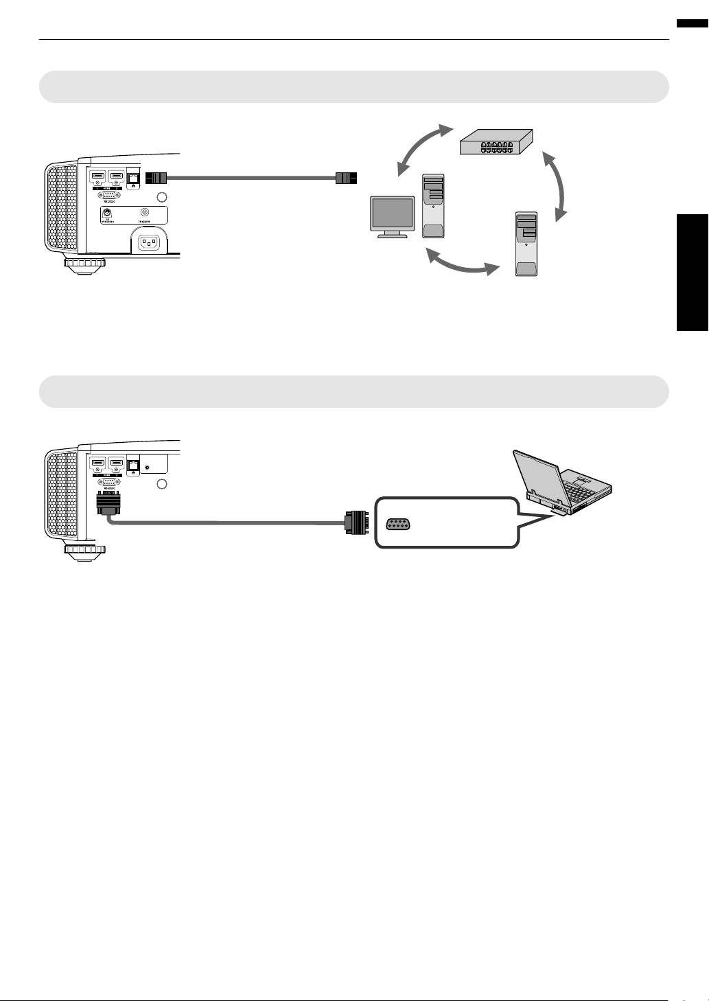
Connecting to the LAN Terminal
Desktop PC, etc.
Server
Hub
Network
Connection Cable
(Sold Separately)
This Unit
To [LAN] Terminal
RS-232C Terminal
Laptop, etc.
RS-232C Connection Cable (Sold Separately)
To [RS-232C] Terminal
This Unit
.
0
The network is used to control this unit. It is not used for sending or receiving video signals.
0
Please contact your network administrator for information concerning the network connection.
0
Set “ECO Mode” to “Off” if RS-232C/LAN communication is performed or the HDMI link function is used in the Standby
mode. (p. 59)
0
For more information on control, please refer to “External Control” (p. 70).
Connecting to the RS-232C Terminal
Set up
.
0
Set “ECO Mode” to “Off” if RS-232C/LAN communication is performed or the HDMI link function is used in the Standby
mode. (p. 59)
0
For more information on control, please refer to “External Control” (p. 70).
23
Page 24
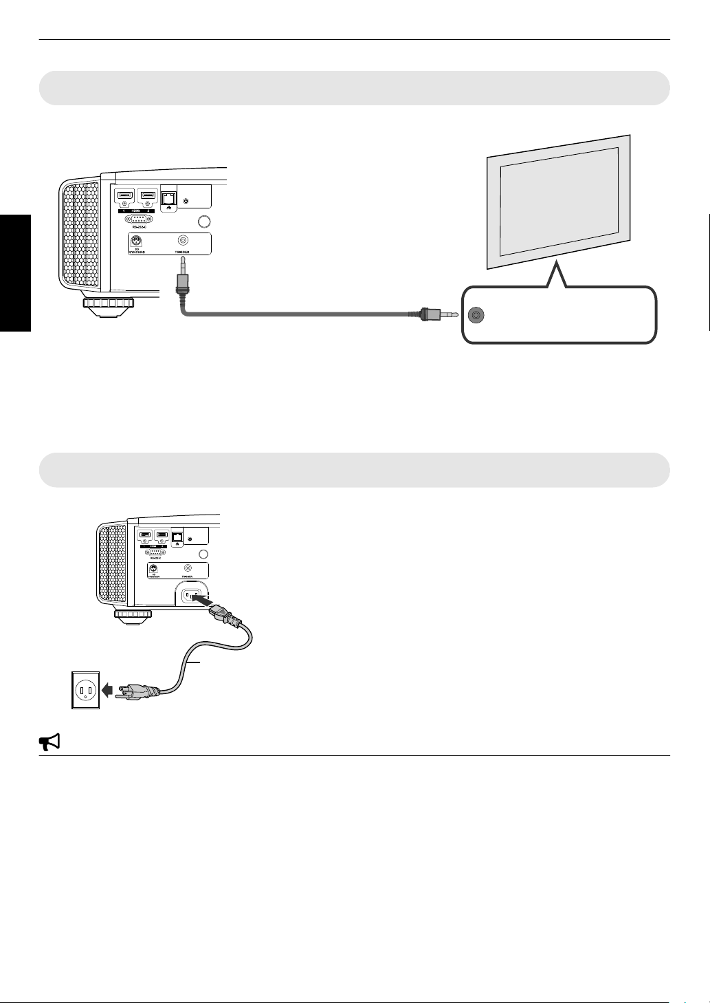
Connecting to the TRIGGER Terminal
Trigger Input Terminal (Ø3.5)
Screen
Trigger Cable (Sold Separately)
To [TRIGGER] Terminal
This Unit
A
B
Power Cord
(Supplied)
Set up
.
0
Do not use it to supply power to other devices.
0
Connecting to the audio terminal of another device may cause the device to malfunction or break down.
0
Using beyond the rated value will cause the unit to malfunction.
0
The trigger terminal outputs a voltage of 12 V. Exercise adequate caution to prevent short circuit.
0
The factory setting is “Off”. To change the setting, configure the “Trigger” item in the menu (
Connecting the Power Cord (Supplied Accessory)
p. 59).
0
0
0
0
0
0
A
Connect
the
power
cord
supplied
to the power input terminal on
the main unit
B
Insert the supplied power plug into the wall outlet.
Precautions to prevent fire and electric shock
The voltage capacity of this unit is large. Please connect it directly to the wall outlet.
When you are not using the equipment, please unplug the power cord from the outlet.
Connect it using only the power cord supplied.
Do not use a voltage other than the indicated power voltage.
Do not damage, break or modify the power cord. Do not place a heavy object on the power cord, or heat or pull it.
Doing so may damage the power cord.
Do not unplug the power cord with wet hands.
24
Page 25
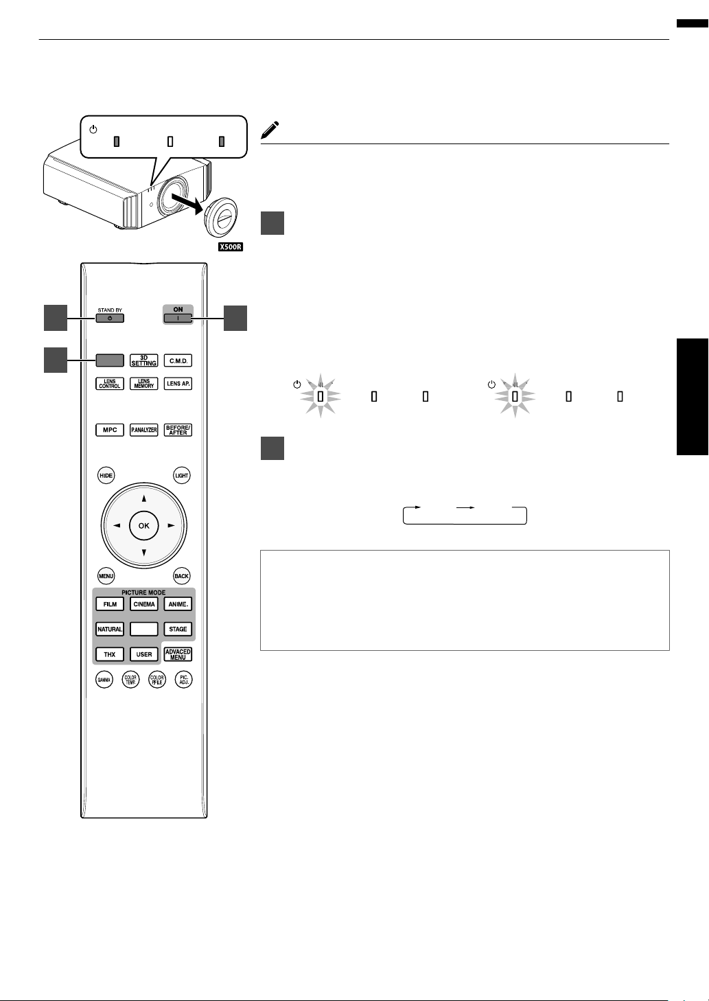
Viewing Videos
LAMP WARNING
STANDBY/ON
LAMP WARNING
STANDBY/ON
During lamp startup
“STANDBY/ON” lights up (green)
In standby state
“STANDBY/ON” lights up (red)
HDMI 1
HDMI 2
LAMP WARNING
STANDBY/ON
INPUT
PHOTO
1
2
3
MEMO
0
When you are using Q, be sure to remove the lens cover.
0
Connect the power cord, and ensure that the “STANDBY/ON” indicator
lights up in red.
1
Turn on the power
Remote control: press the C [ON] button
Projector unit: press the A [STANDBY/ON] button
0
The “STANDBY/ON” indicator light switches
goes off after the unit starts up).
0
(S R) The motorized lens cover opens.
.
2
Choose the image to project
Pressing the [INPUT] button on the projector unit or remote control each
time switches the input mode as follows.
from red to green (light
Operate
.
0
Play back the selected device to project the image.
To hide the image temporarily
Press the [HIDE] button on the projector unit or remote control
0
The “STANDBY/ON” indicator light starts to blink in green.
0
Press the [HIDE] button again to resume display of the image.
0
The power cannot be turned off when the image is temporarily hidden.
25
Page 26
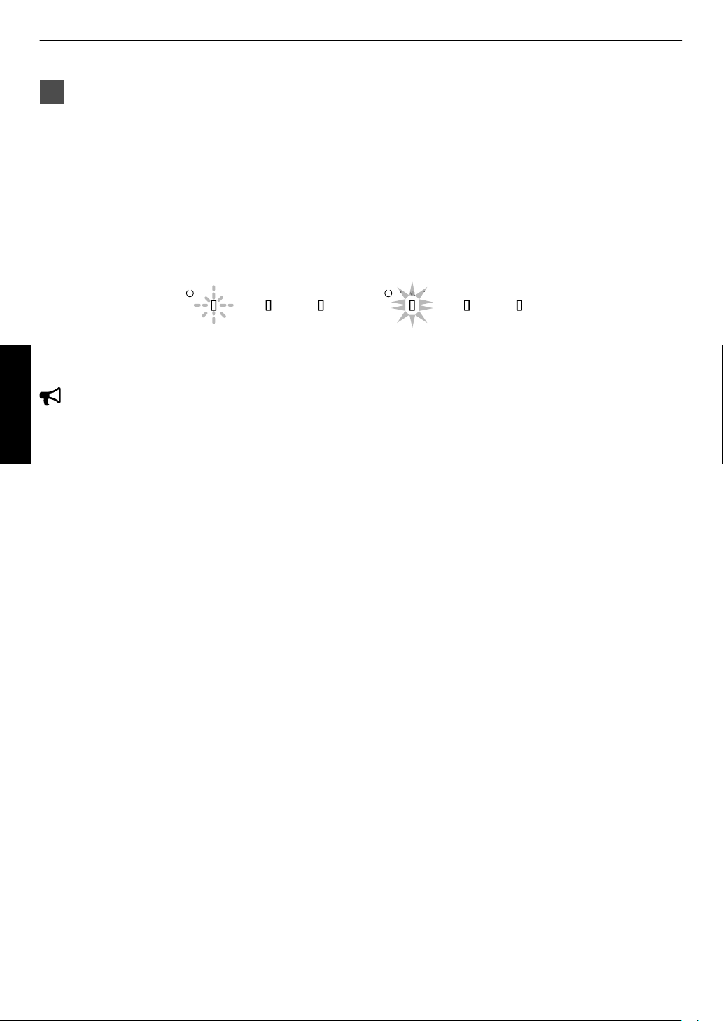
3
LAMP WARNING
STANDBY/ON
LAMP
WARNING
STANDBY/ON
In standby state
“STANDBY/ON” lights up (red)
In the Cool-down mode
“STANDBY/ON” blinking (red)
Turn off the power
Remote control: press the B [STAND BY] button
Projector unit: press the A [STANDBY/ON] button
0
While the “Are you sure you want to turn off?” message is displayed, press the button again.
0
The lamp turns off, and the “STANDBY/ON” indicator switches from a green light to a red blinking light.
0
After the light goes off, the fan will run for about 100 seconds to cool down the lamp (Cool-down mode).
Do not disconnect the power cable while cooling is in progress.
0
After about 100 seconds, the “STANDBY/ON” indicator switches from a blinking red to a solid red light.
.
0
(Q) Attach the lens cover.
0
(S R) The motorized lens cover closes.
Operate
CAUTION
0
The power cannot be turned off within approximately 60 seconds after it has been turned on.
0
After the light goes off, the fan will run for about 100 seconds to cool down the lamp (Cool-down mode).
Do not disconnect the power cable while cooling is in progress.
0
The power cannot be turned on again while cooling is in progress (100 seconds).
0
Pull out the power plug when the unit is not to be used for a prolonged period of time.
26
Page 27

Adjusting the Projector Screen
Focus
Shift (Screen Position)
Adjustment
Zoom (Screen Size)
Adjustment
ABCD
ABCD
ABCD
Focus Adjustment
INPUT
PHOTO
1
2
Adjusting the Lens According to the Projection Position
Press the [LENS CONTROL] button, and use the
1
[JKH I] keys to adjust Focus, Zoom (screen size),
and Shift (screen position)
.
0
Pressing the [LENS CONTROL] or [OK] button each time switches
the mode in the following sequence:
“Focus”"“Zoom”"“Shift”"“Focus”...
Operate
.
Press the [MENU] button once, or the [BACK] twice,
2
to end adjustment.
0
Operation of the lens control feature is disabled when the lens lock
is set to “On”.
27
Page 28
Saving and Retrieving Adjustment Settings
MENU
BACK
-----
-----
-----
-----
-----
-----
-----
-----
-----
>>
-----
Back
Operate
Select
Exit
Lens Memory Save
Installation
INPUT
PHOTO
2
4
3
The Focus, Zoom, and Shift settings can be saved or retrieved, so you can
easily to a different
switch
0
Pressing the [LENS MEMORY] button
following sequence: “Lens Memory Save”"“Lens Memory Select”"“Lens
Memory Name Edit”"“Lens Memory Save”...
0
In a state where no adjustment settings are saved (factory default), only
“Lens Memory Save” is displayed.
0
Operation of the lens control feature is disabled when the lens lock is set
to “On”.
Saving an adjustment data
Adjust focus, zoom, or shift (p. 27)
1
Press the [LENS MEMORY] button to display “Lens
2
Memory Save”
Operate
0
You can also save an adjustment data by selecting
“Installation”"“Lens Control”"“Lens Memory
aspect ratio (screen size) according to the image.
each time switches the mode in the
Save” from the menu.
Select the item to save, and press the [OK] button
3
0
The adjustment data is saved.
0
Items with no adjustment data saved are displayed as [----].
0
If
.
you have selected an
item for which an adjustment data has already
been saved, the old data will be overwritten.
0
You can change the name when saving an item. (p. 29)
0
The maximum number of items can be saved is 10 for S
R
and 5 for Q.
Press the [MENU] button to exit
28
4
Page 29
Retrieving an adjustment data
MENU
BACK
-----
-----
-----
MEMORY2
-----
-----
-----
-----
-----
>>
MEMORY1
Back
Operate
Select
Exit
Lens Memory Select
Installation
MENU
BACK
-----
-----
-----
MEMORY2
-----
-----
-----
-----
-----
>>
MEMORY1
Lens Memory Name Edit
Back
Operate
Select
Exit
Installation
MENU
>>
MEMORY1
}
?
.
y
l
Y
L
{
=
,
x
k
X
K
]
/
0
w
j
W
J
[
-
9
v
i
V
I
>
+
8
y
h
U
H
<
*
7
t
g
T
G
)
&
6
s
f
S
F
(
%
5
r
e
R
E
~
$
4
q
d
Q
D
|
#
3
p
c
P
C
;
"
2
o
b
O
B
\
^
z
M
Z
m
@
:
!
1
n
a
N
A
SPACE
OKAll ClearClear
Name
Character List
Selection Cursor
Input Cursor
BACK
Back
Operate
Select
Exit
Lens Memory Name Edit
Installation
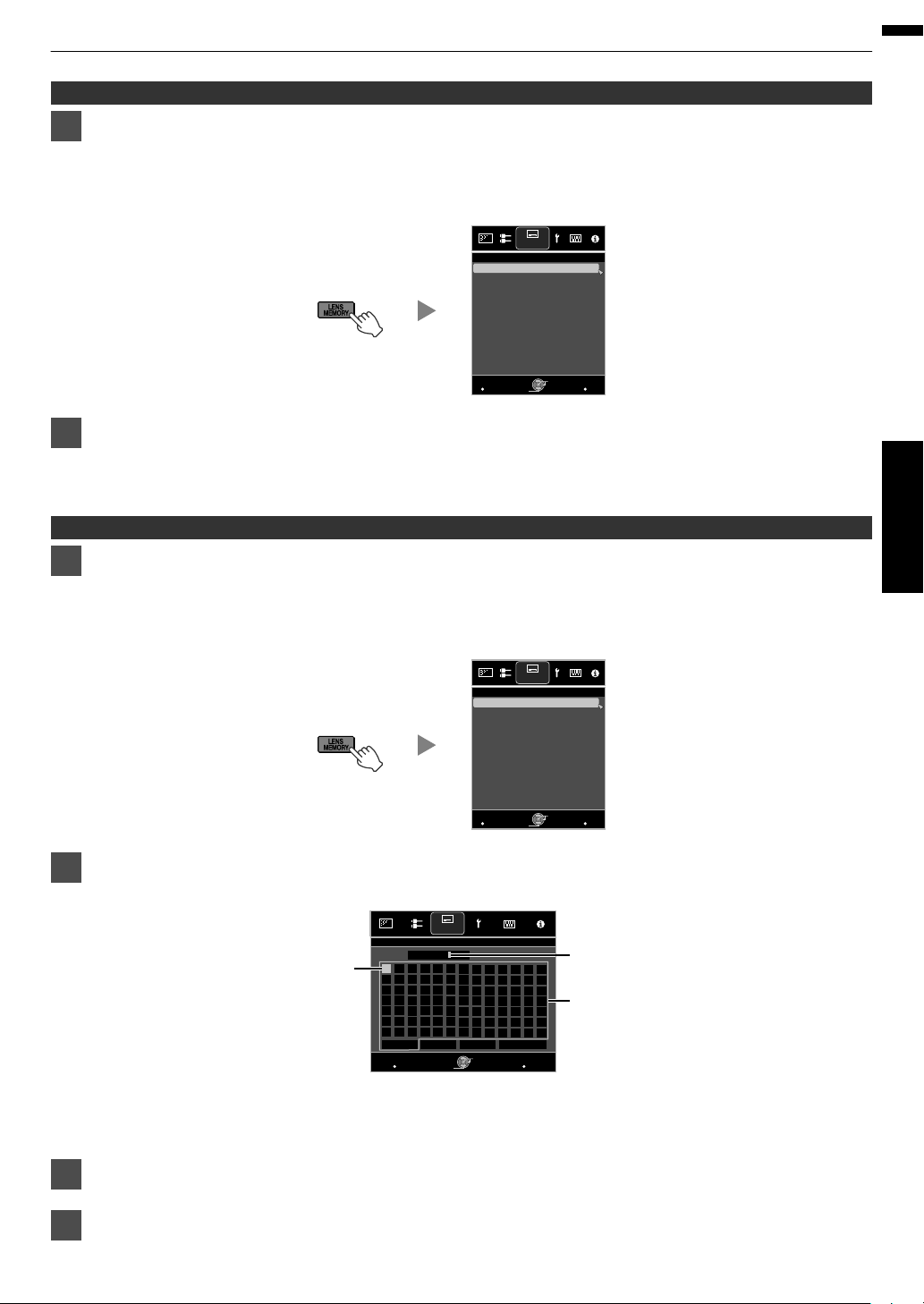
Press the [LENS MEMORY] button to display “Lens Memory Select”
1
0
Pressing
the [LENS MEMORY] button
each time switches the mode in the following sequence: “Lens Memory
Select”"“Lens Memory Save”"“Lens Memory Name Edit”"“Lens Memory Select”...
0
You can also retrieve an adjustment data by selecting “Installation”"“Lens Control”"“Lens Memory Select”
from the menu.
.
Select the adjustment data to retrieve, and press the [OK] button
2
0
The retrieved data is adjusted automatically.
0
If no adjustment data has been saved, the item will be grayed out and cannot be selected.
Renaming an adjustment data
Press the [LENS MEMORY] button to display “Lens Memory Name Edit”
1
0
Pressing the [LENS MEMORY] button each time switches the mode in the following sequence: “Lens Memory
Select”"“Lens Memory Save”"“Lens Memory Name Edit”"“Lens Memory Select”...
0
You can also edit an adjustment data by selecting “Installation”"“Lens Control”"“Lens Memory Name Edit”
from the menu.
Operate
.
Select the adjustment data to edit, and press the [OK] button
2
0
An edit screen appears.
.
0
You can input up to 10 characters.
0
Characters that are usable include alphabets (upper or lower case), numeric characters, and symbols.
0
Pressing the [Back] button cancels the content that is currently being edited, and exits the edit mode.
After renaming, select “OK” and press the [OK] button
3
Press the [MENU] button to exit
4
29
Page 30
Adjusting Image Quality Automatically According to the Viewing
Projector
Viewer
Viewing
Distance
Screen Size
Screen
- Front View -
>>
MENU
BACK
0
MENU
BACK
0
3
21
Back
Operate
Select
Exit
Back
Operate
Select
Exit
Light
3m
100inch
Off
On
Wall C olor
Viewing Distance
Screen Size
Screen No.
Screen Adjust
Off
Front
Environment Setting
High Altitude Mode
Anamorphic
Pincushion
Keystone
Installation Style
Pixel Adjust
Lens Control
Installation Installation
Off
Environment Setting
Off
On
Adjust
>>
MENU
BACK
3
21
Back
Operate
Select
Exit
Light
3m
100inch
Off
On
Wall Color
Viewing Distance
Screen Size
Screen No.
Screen Adjust
Installation
Environment Setting
Adjust
Environment
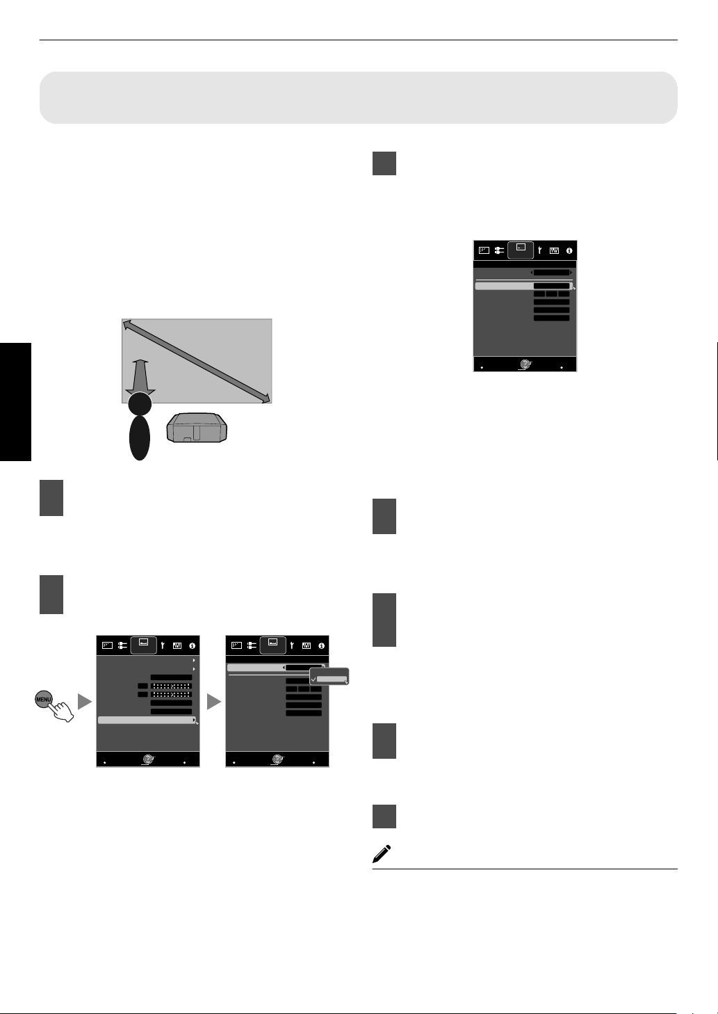
By configuring “Environment Setting” according to the
viewing environment, image quality adjustment and
correction according to environmental differences are
performed
automatically
minimize
to
influence on the
any
image quality.
0
“Environment Setting” is applied separately from the
individually adjusted data.
0
Screen correction cannot be performed when “Color
Profile” is set to “x.v.Color”.
.
Set Screen Adjust
3
By selecting the optimal correction mode
according to the characteristics of the screen in
use, corrections can be performed to reproduce
natural images with balanced colors.
Operate
1
2
Press the [MENU] button to display
the menu
Q:
Press the [ENV.SETTING] button on the remote
control to open the “Environment Setting” menu.
Select “Installation”"“Environment
Setting”"“On” from the menu
.
0
When “Environment Setting” is set to “Off”,
“Screen Size”, “Viewing Distance”, and “Wall
Color” are grayed out and cannot be selected.
.
0
This item is not available
when “Color Profile” is
set to “Off”.
0
Select a type from “1” to “106”.
0
For information on the screen and the
corresponding
correction mode, please visit
website.
http://www3.jvckenwood.com/english/projector/screen/
Select “Screen Size” to configure the
4
screen size to use
0
Select the closest screen size setting from the
range between “60inch” and “200inch” (in 10inch increments).
Select “Viewing Distance” to
5
configure the viewing distance
(distance to the screen)
0
Select the closest viewing distance
the range between “1 m” and “10 m”.
0
For more details on the height, please refer to
“Screen Size and Projection Distance”p. 75.
Select “Wall Color” to configure the
6
wall color
0
If the wall is dark
in color, select “Dark”. For walls
with a color other than dark color, select “Light”.
Press the [MENU] button to exit
7
setting from
our
30
MEMO
0
You can utilize the optional optical sensor and
dedicated software to make finer adjustments.
For more information on the dedicated software,
please visit our website.
http://www3.jvckenwood.com/english/download/
index.html
Page 31

Adjusting the Screen Size (Aspect)
MENU
BACK
Auto
16:9
Off
Auto
Picture Position
3D Setting
Progressive
Mask
Aspect
Control with HDMI
Color Space
Input Level
Input Signal
Auto
Back
Operate
Select
Exit
Zoom
16:9
4:3
4:3
2.35:1
(Cinema
Scope)
Setting
Input Image
Output Image
1280×1024
1920×1200
Full
Just
Auto
Setting
Output Image
Input Image
The screen size of the projected image can be adjusted
optimally according to the original screen size (aspect)
that has been input.
Press the [MENU] button to display
1
the menu
Select “Input Signal”"“Aspect” from
2
the menu
.
Setting Description
4:3 Sets the screen size to 4:3. For
HD signals, the two sides are
reduced.
16:9 Sets the screen size to 16:9.
For SD signals, the two sides
are expanded.
Zoom Enlarges the entire image.
* Not selectable in the case
HD signals.
Auto Positions the image at the
center with the entire image
enlarged.
Just Displays the input image in the
actual size.
Full Fills the entire screen with the
image with the size (aspect)
the input image ignored.
0
This item is grayed out and cannot be adjusted when
there is no signal, signal is out of range, or during 3D
or 4K input.
Displayed
only during
video signal
input.
of
Displayed
only during
PC signal
input.
of
Example of input image and screen size
HDMI Signal Input
.
PC Signal Input
.
Operate
3
Press the [MENU] button to exit
31
Page 32

Viewing 3D Movies
3D GLASSES
3D SYNCHRO EMITTER
PK-EM2
PK-EM1
3D SYNCHRO EMITTER
This Unit
By using the 3D GLASSES (PK-AG1, PK-AG2, or PK-AG3) and 3D SYNCHRO EMITTER (PK-EM1 or PK-EM2), both
sold separately, you can enjoy 3D video images.
0
For 3D GLASSES and 3D SYNCHRO EMITTER that are compatible with this unit, please refer to
Accessories”p. 11.
Installing the 3D SYNCHRO EMITTER
1
Connect 3D SYNCHRO EMITTER to the [3D SYNCHRO] terminal on the main unit
Operate
.
Adjust the 3D SYNCHRO EMITTER position so that the 3D GLASSES can receive
2
signals from the 3D SYNCHRO EMITTER
0
For more details, please refer to the instruction manuals 3D GLASSES and 3D SYNCHRO EMITTER.
“Optional
32
Page 33

Viewing 3D Movies
INPUT
Connect this unit to a 3D-compatible
1
HDMI device, and turn on the power
to play back the 3D video image
0
details on how to
For
please refer to the instruction manual of the
player or recorder in use.
0
When 3D signals are received,
switches automatically to the 3D format.
0
This unit supports the following 3D formats.
- Frame packing
- Side-by-side
- Top-and-bottom
0
the default setting, “3D
In
for automatic projection of 3D images.
If the image does not switch to 3D automatically
A
Press the [3D SETTING] button to
display “3D Setting”
B
Select “3D Format”
Q: Press the [3D FORMAT] button on the remote
control
play back 3D video images,
the video image
Format” is set to “Auto”
0
Pressing the [3D FORMAT] button each time
switches the mode in the following sequence:
“Auto”"“Side by Side”"“Top and
Bottom”"“2D”"“Auto”...
0
You can also perform setting from “Input
Signal”"“3D Setting”"“3D Format” in the
menu.
Format Description
Auto The format is detected and
configured automatically.
Side by Side Select this setting if the 3D input
signal is of the side-by-side
format.
Top and Bottom Select this setting if the 3D input
signal is of the top-and-bottom
format.
2D Select this setting if 2D images
are falsely recognized as 3D
ones.
Turn of the power of the 3D GLASSES
2
and put them on
0
The PK-AG1 powers on automatically.
Operate
.
33
Page 34

Converting 2D Movies to 3D Movies for Viewing
>
MENU
BACK
0
0
INPUT
Back
Operate
Select
Exit
Auto
Crosstalk Cancel
Parallax
2D to 3D conversion
3D Format
3D Setting
Input Signal
On
1
2
Operate
Press the [3D SETTING] button to
display “3D Setting”
0
The [3D SETTING] button is positioned
differently on the remote control depending on
the model in use. (p. 17)
Select “2D to 3D conversion” followed
by “On”, and press the [OK] button
0
You can also perform setting from “Input
Signal”"“3D Setting”"“2D to
the menu.
.
3D conversion” in
3
Press the [MENU] button to exit
MEMO
0
Depending on the movies, 3D
what you expected.
0
This item is grayed out and displayed as “Off” during
3D or 4K input.
effect may be less than
Adjusting 3D Movies
3D video images may appear differently to different
viewers. It may also be affected by your physical
condition at the time of viewing.
You are therefore recommended to adjust the video
images accordingly.
Press the [3D SETTING] button to
1
display “3D Setting”
0
The [3D SETTING] button is positioned
differently on the remote control depending on
the model in use. (p. 17)
0
You can also perform setting from “Input
Signal”"“3D Setting” in the menu.
Adjusting parallax (Parallax)
Adjust the displacement of the image for the left
and right eyes separately to obtain the best 3D
effect.
0
To do so, use the H I
0
Setting range: -15 to +15
keys to move the cursor.
Adjusting crosstalk (Crosstalk Cancel)
Double images (overlapping of the left image with
the one on the right or vice versa) can be reduced
to deliver a clear quality.
0
To do so, use the H I keys to move the cursor.
0
Setting range: -8 to +8
0
Adjustment cannot be made when “2D to 3D
conversion” is set to “On”.
Press the [MENU] button to exit
2
34
Page 35

Selecting an Image Quality According to the
INPUT
PHOTO
1
Video Type
Setting the Picture Mode
You can adjust the image quality according to the type of video image you are
viewing.
Press the [PICTURE MODE] button to select “Picture
1
Mode”
0
You can also perform setting from “Picture Adjust”"“Picture Mode”
in the menu.
Item Description
Film*1S R
Cinema*1 Reproduces the image in vivid colors based on the
Animation*1 Suitable for animated works.
Natural*1
Photo*1S R Setting for displaying photo images.
Stage*1 Suitable for concerts or theatrical works.
THX*1 S R Image quality certified by THX.
User 1 to User 4 *3 Enables user-defined image quality data to be saved
4K 50/60p *4 *5 Picture mode when the input signal is
*1 For Picture modes with the *1 mark, the optimal settings for 2D and 3D
signals are stored separately
selected mode.
0
Edited settings will also be saved separately.
0
No changes will be made to the Picture mode name.
*2 DCI is the abbreviation for Digital Cinema Initiatives.
*3 To view videos that support the x.v.Color format, select a user setting
(“User 1” to “User 4”) in “Picture Mode”, and set “Color Profile” to
“x.v.Color”.
*4 When the input signal is “3840×2160/50Hz” or “3840×2160/60Hz”, the
picture mode is
and cannot be adjusted.
*5 This item won’t be displayed when the input signal is other than
“3840×2160/50Hz” or “3840×2160/60Hz”.
Reproduces faithfully the texture of movie films.
DCI standard. Suitable for all movies. *2
Image quality that focuses on natural color and
gradation reproduction. Suitable for drama footage, etc.
and retrieved.
“3840×2160/50Hz” or “3840×2160/60Hz”.
and applied automatically according to the
fixed at “4K 50/60p”, and some functions are grayed out
Adjust/Set
35
Page 36

Setting the Color Profile
PHOTO
By setting the “Color Profile” (color space information) according to the “Picture Mode”, you
can fine-tune the image quality according to the movie you are viewing.
After configuring “Picture Mode” (p. 35), press the [COLOR
1
P.FILE] button
0
0
0
Pressing the [COLOR P.FILE] button each time switches the “Color Profile” data for
the “Picture Mode” in sequence.
The selectable “Color Profile” settings vary according to the “Picture Mode” and also
whether the signal is 2D or 3D.
"
You can also perform setting from “Picture Adjust”
“Color Profile” in the menu.
List of “Color Profile” for “Picture Mode”
Picture Mode 2D Signal Input 3D Signal Input Description
Cinema Cinema
Standard Standard Color space of the HDTV standard. *1
—
Animation Animation
Standard Standard Color space of the HDTV standard. *1
—
Natural Natural
Adjust/Set
Stage Stage
User 1 to User 4 Standard When “Picture Mode” is set to any of the settings from “User 1” to “User 4”, you
Standard Standard Color space of the HDTV standard. *1
—
Standard Standard Color space of the HDTV standard. *1
—
Cinema
Animation
Natural
Stage
3D Cinema
3D Video
3D Animation
3D Stage
x.v.Color*2*3 Color space that is close to that of the x.v.Color standard.
Off Disables color space adjustment.
Custom1 to Custom5 Saves the auto calibration values.
3D Cinema Color space suitable for all 3D movies.
3D Animation Color space suitable for 3D animation works.
3D Video Color space suitable for 3D broadcasts.
3D Stage Color space suitable for 3D concerts, 3D theatrical works, etc.
—
—
—
—
Q
Color space suitable for all movies.
Color space that is suitable for animated works.
Color space that is suitable for drama footage, etc.
Color space that is suitable for concerts, theatrical performances, etc.
can select one of the “Color Profile” shown on the left.
0
See above for the description of the respective “Color Profile”.
0
To perform auto calibration, you need to get ready a commercially available
optical sensor and a dedicated software program. For more details, please
refer to our website.
*1 HDTV is the abbreviation for High Definition Television.
*2 To view videos that support the x.v.Color format, select a user setting (“User 1” to “User 4”) in “Picture Mode”, and set “Color
Profile” to “x.v.Color”.
*3 x.v.Color is a wide color space standard for used in videos; it includes wider color gamut than the HDTV standard.
36
Page 37

List of “Color Profile” for “Picture Mode”
Picture Mode 2D Signal Input 3D Signal Input Description
Film Film 1
Film 2
Film 3
—
Cinema Cinema 1
Cinema 2
Standard Standard Color space of the HDTV standard. *2
—
Animation Anime 1
Anime 2
Standard Standard Color space of the HDTV standard. *2
—
Natural Video
Standard Standard Color space of the HDTV standard. *2
—
Photo AdobeRGB
Standard Standard Color space of the HDTV standard. *2
—
Stage Stage
Standard Standard Color space of the HDTV standard. *2
—
THX THX*4 3D THX*4 Color space of the THX standard.
User 1 to User 4 Standard When “Picture Mode” is set to any of the settings from “User 1” to “User 4”, you can select
Cinema 1
Cinema 2
Anime 1
Anime 2
Video
AdobeRGB
Stage
3D Cinema
3D Video
3D Animation
3D Stage
3D Photo
x.v.Color*5*6 Color space of the x.v.Color standard.
Off Disables color space adjustment.
Custom1 to Custom5 Saves the auto calibration values.
—
—
—
3D Film*1 Color space suitable for 3D movies recorded in film.
—
—
3D Cinema Color space suitable for all 3D movies.
—
—
3D Animation Color space suitable for 3D animation works.
—
3D Video Color space suitable for 3D video materials.
—
3D Photo Color space suitable for 3D photo materials.
—
3D Stage Color space suitable for 3D concerts, 3D theatrical works, etc.
S R
Color space that is close to the characteristics of Eastman Kodak Company movie films.
Color space that is close to the characteristics of FUJIFILM Corporation movie films.
Color space suitable for digitally remastered piece of art based on a Technicolor film.
Color space with rich colors that are characteristic of movies.
Color space that is close to that of the DCI standard.
Color space that is suitable for CG animation works. Ideal for animated works with bright
colors.
Color space that is suitable for cel animation works. Ideal for animated works with light
colors.
Color space that is suitable for TV programs, dramas, sports programs, etc.
Color space of the AdobeRGB standard. *3
Color space that is suitable for concerts, theatrical performances, etc.
one of the “Color Profile” shown on the left.
0
See above for the description of the respective “Color Profile”.
0
To perform auto calibration, you need to get ready a commercially available optical
sensor and a dedicated software program. For more details, please refer to our
website.
*1 The value is fixed during 3D signal input, and selection cannot be made.
*2 HDTV is the abbreviation for High Definition Television.
*3 AdobeRGB is a color space with a wide gamut as defined by Adobe.
Adobe is a registered trademark or trademark of Adobe Systems Incorporated in the United States and other countries.
*4 Color Profile is fixed when “THX” is selected as the “Picture Mode”.
*5 To view videos that support the x.v.Color format, select a user setting (“User 1” to “User 4”) in “Picture Mode”, and set “Color
Profile” to “x.v.Color”.
*6 x.v.Color is a wide color space standard for used in videos; it includes wider color gamut than the HDTV standard.
37
Adjust/Set
Page 38

Adjusting to the Preferred Color (Color Management)
>
MENU
BACK
0
0
0
0
Back
Operate
Select
Exit
Red
On
Film 1
Before
Brightness
Saturation
Hue
Axis Position
Color Selection
Color Management
Color Profile
Picture Adjust
Color Profile
Reset
Off
On
>
MENU
BACK
0
0
0
0
A
B
MagentaBlue
Cyan
Green Yellow
Red
Clockwise rotation: -
Counterclockwise
rotation: +
Axis Position (Image)
Adjustable range when
Red is selected: ± 30°
with Red as the center
Back
Operate
Select
Exit
Red
On
Film 1
Before
Reset
Brightness
Saturation
Hue
Axis Position
Color Selection
Color Management
Color Profile
Picture Adjust
Color Profile
Based on the setting of the selected “Color Profile”, you can adjust each of the following colors according to your
preference: Red, Orange, Yellow, Green, Cyan, Blue, and Magenta.
1
Press the [ADVANCED MENU] button to display the “Color Profile” menu
Set “Color Management” to “On”, and press the [OK]
2
button
0
You can also perform setting
Management” in the menu.
3
Adjust to the preferred color.
A
Select “Color Selection”, and press the H I keys to
select the color to adjust
0
For color adjustment, select the color from the
following: “Red”, “Orange”, “Yellow”, “Green”,
“Cyan”, “Blue”, “Magenta”.
B
Adjust the selected color
from “Picture Adjust”"“Color Profile”"“Color
Adjust/Set
Item
Axis Position -30 to 30 Fine-tune the position
Hue -30 to 30 Adjusts the hue (color
Saturation -30 to 30 Adjusts the color
Brightness -30 to 30 Adjusts the
0
4
Selecting “Reset” resets all the adjustment data.
0
Pressing the [BEFORE/AFTER] button on the
remote control enables you to check the image
before adjustment.
Press the [MENU] button to exit
Setting Range
Description
of the central axis of
the selected color.
tone).
saturation (vividness).
-30 (dull) to +30 (vivid)
brightness.
-30 (dark) to +30
(bright)
38
Page 39

Adjusting Movies for Increased
>>
MENU
BACK
0
0
0
0
INPUT
Back
Operate
Select
Exit
Auto
On
Before Reset
NR
Smoothing
Dynamic Contrast
Enhance
Original Resolution
4K e-shift
MPC Level
Picture Adjust
Expressiveness (Multiple Pixel Control)
The new image-processing algorithm developed by JVC
helps to create a natural impression that is sharper at
areas in focus, and softer at areas that are not in focus,
enabling you to enjoy highly expressive 4K images with
a greater sense of depth.
Press the [MPC] button to display the
1
adjustment menu
0
You can also perform setting from “Picture
Adjust”"“MPC Level” in the menu.
.
Make adjustments according to your
2
preference based on the setting
of the
selected “Picture Mode”
* The factory setting varies with the “Picture
Mode”.
0
In the default “Original Resolution”
setting (“Auto”), the
resolution is set automatically.
0
By increasing the setting range, you can expect
enhanced effects.
0
Images are displayed in the original resolution (2K)
when “4K e-shift” is set to “Off”.
0
The setting is fixed at “On” during 4K signal input.
0
During
3D signal input and
when “2D to 3D conversion”
is set to “On”, the setting is fixed at “Off”.
0
“Original Resolution”, “Zone”, “Enhance”, “Dynamic
Contrast”, and “NR” can be
adjusted even when “4K e-
shift” is set to “Off”.
* MPC is the abbreviation for Multiple Pixel Control.
3
Press the [MENU] button to exit
Toggling between the States before
and after Adjustment
Pressing the [BEFORE/AFTER] button on the remote
control enables you to toggle between the states before
adjustment (BEFORE) and after adjustment (AFTER).
Adjust/Set
Item Setting Description
4K e-shift On (4K)/Off
(2K)
Original
Resolution
Auto/4K/
1080p/
Switches the display
resolution.
For selecting a resolution for
the content you are viewing.
1080i/720p/
480p
Enhance 0 to 100 Enhances the sharpness of
the image.
Dynamic
Contrast
0 to 100 Enhances the contrast of the
image.
Smoothing 0 to 100 Enhances the blurriness of
the image for a softer effect.
NR 0 to 10 For reducing the noise of the
video image.
39
Page 40

About the analysis screen
Low High
Red Yellow Green Cyan
Blue
Frequency
Orange
Purple
Pressing the [P.ANALYZER] button on the remote control displays the analysis screen. The operation varies with the
state of the OSD.
1
Press the [P.ANALYZER] button
The frequency components of the input image are displayed.
.
0
The frequency components are distinguished using different colors.
0
When setting the “Original Resolution” manually, select “4K” if high-frequency components constitute the majority,
and a lower resolution if there are more low-frequency components.
.
2
Adjust/Set
Make adjustments while looking at the analysis screen
A
Press the [MPC] button to display the adjustment menu
You can also perform setting from “Picture Adjust”"“MPC Level” in the menu.
B
Make adjustments according to your preference based on the setting of the selected “Picture Mode”*
0
With the analysis screen displayed, selecting “Enhance” displays the area in “cyan” where the “Enhance”
effect is applied.
Pressing the [P.ANALYZER] button while “Enhance” is selected also displays the area.
0
With the analysis screen displayed, selecting “Dynamic Contrast” displays the area in “yellow” where the
“Dynamic Contrast” effect is applied.
Pressing the [P.ANALYZER] button while “Dynamic Contrast” is selected also displays the area.
0
the analysis screen displayed,
With
“Smoothing” or “NR” effect is applied.
Pressing the [P.ANALYZER] button while “Smoothing” or “NR” is selected also displays the area.
* You can make adjustments with the analysis screen displayed.
Increasing the value enhances the effect and the color displayed is darker.
selecting “Smoothing” or “NR” displays the area in “magenta” where the
3
40
Press the [P.ANALYZER] to exit the analysis screen
Page 41

Fine-tuning the Image Quality
0
255
0 255
The photos are for illustrative purposes only.
Input Value
Output Value
A
B
AB
0
255
0 255
A
B
AB
The photos are for illustrative purposes only.
Input Value
Output Value
PHOTO
Adjusting the Output Value of the Projected Image (Gamma)
You can adjust the output value of the projected image with respect to the video signal input.
Example of gamma adjustment
The overall image appear brighter with respect to the original image, making the dark areas more visible.
.
Increases the contrast with respect to the original image, creating a greater sense of depth.
.
1
Press the [GAMMA] button
0
Pressing the [GAMMA] button each time switches the setting in sequence.
0
You can also perform setting from “Picture Adjust”"“Gamma” in the menu.
* The setting value varies with the model in use, as well as the “Picture Mode”.
Gamma Settings for Different “Color Profile” Q
Color Profile Selectable Settings Description
Standard
Cinema
Animation
Natural
Stage
3D Cinema
3D Video
3D Animation
3D Stage
Off
x.v.Color Normal* Recommended setting for normal viewing.
* When “Color Profile” is set to “x.v.Color”, the setting is fixed at “Normal”.
Normal Recommended setting for normal viewing.
Brightness Priority Places more emphasis on the brightness compared to the Normal setting.
Contrast Priority Places more emphasis on the contrast compared to the Normal setting.
Gradation Priority Places more emphasis on the gradation compared to the Normal setting.
Custom 1 to Custom 3 Fine-tunes the gamma setting according to the user’s preference.
Adjust/Set
41
Page 42

Gamma Settings for Different “Color Profile” S R
>
MENU
BACK
0
0
0
Back
Operate
Select
Exit
White
2.2
Custom 1
Reset
Bright Level
Dark Level
Picture Tone
Color Selection
Correction Value
Gamma
Picture Adjust
Gamma
Color Profile Selectable Settings Description
Film 1 Film 1 Image is close to the characteristics of Eastman Kodak Company movie
films.
Film 2 Places more emphasis on the gradation compared to the “Film 1” setting.
Custom 1 to Custom 3 Fine-tunes the gamma setting according to the user’s preference.
Film 2 Film 1 Image is close to the characteristics of FUJIFILM Corporation movie films.
Film 2 Places more emphasis on the contrast compared to the “Film 1” setting.
Custom 1 to Custom 3 Fine-tunes the gamma setting according to the user’s preference.
Film 3 Film 1 Places emphasis on the gradation.
Film 2 Places emphasis on the contrast.
Custom 1 to Custom 3 Fine-tunes the gamma setting according to the user’s preference.
3D Film Film 1 Places emphasis on the gradation.
Film 2 Places emphasis on the contrast.
Custom 1 to Custom 3 Fine-tunes the gamma setting according to the user’s preference.
Standard
Cinema 1/Cinema 2
Anime 1/Anime 2
Video
AdobeRGB
Stage
Adjust/Set
3D Cinema
3D Video
3D Animation
3D Stage
3D Photo
Off
x.v.Color Normal*1 Recommended setting for normal viewing.
THX
3D THX
*1 When “Color Profile” is set to “x.v.Color”, the setting is fixed at “Normal”.
*2 When “Color Profile” is set to “THX”/“3D THX”, the setting is fixed at “THX”.
Normal Recommended setting for normal viewing.
Brightness Priority Places more emphasis on the brightness compared to the Normal setting.
Contrast Priority Places more emphasis on the contrast compared to the Normal setting.
Gradation Priority Places more emphasis on the gradation compared to the Normal setting.
Custom 1 to Custom 3 Fine-tunes the gamma setting according to the user’s preference.
THX*2 Video of the THX standard.
Fine-tuning to the Preferred Gamma Setting
You can perform fine adjustments based on the selected gamma adjustment setting.
1
Press the [ADVANCED MENU] button to display the gamma menu
0
You can also perform setting from “Picture Adjust”"“Gamma” in the menu.
42
Page 43

2
C
B
A
D
0 255
0
255
D”
Gamma Curve
Input Value
Output Value
Dark
Dark
Bright
Bright
Adjust to the preferred setting
Item Description Setting
Color Selection Select “Color Selection”, and select the color to adjust White/Red/Green/Blue
Picture Tone Adjusts the overall brightness automatically for a well-balanced
result without compromising the gradation of the image.
-16 (darkens image for an
underexposed effect) to +16
(brightens
image
for
an
overexposed
effect)
Dark Level
Adjusts the dark areas of the input image. (Each of White/Red/
Green/Blue can be adjusted.)
0
To do so, use the H I keys to move the cursor.
Bright Level Adjusts the bright areas of the input image. (Each of White/Red/
Green/Blue can be adjusted.)
0
To do so, use the H I keys to move the cursor.
-7 (darkens the shadows) to +7
(brightens the shadows)
-7 (darkens the highlights) to +7
(brightens the highlights)
* Adjustment cannot be made when “Color Profile” is set to “x.v.Color”.
Selecting the Default Value for Making Adjustments
0
When one of “Custom 1” to “Custom 3” is selected in “Gamma”, you can select a “Correction Value”.
0
Select “Correction Value”, and press the H I keys to select a correction value (setting value) as a base value for
adjustment.
0
For details on the correction value (setting value), please refer to
Q
Normal, Brightness Priority, Contrast Priority, Gradation Priority, 1.8, 1.9, 2.0, 2.1, 2.2, 2.3, 2.4, 2.5, 2.6, import
S R
When “Picture Mode” is set to “Film”:
Film 1, Film 2, import
When “Picture Mode” is set to a value other than “Film”:
Normal, Brightness Priority, Contrast Priority, Gradation Priority, 1.8, 1.9, 2.0, 2.1, 2.2, 2.3, 2.4, 2.5, 2.6, import
0
The smaller the value, the brighter the dark areas of the image will become. At the same time, the bright areas will
appear blown out.
0
Selecting “import” enables you to import gamma data that is created externally. The factory setting for “import” is
the same as the “Normal” setting.
For more details, please refer to our website.
http://www3.jvckenwood.com/projector/support/index.html
p. 41 and p. 42.
Adjust/Set
About gamma adjustment
0
When the gamma curve is a straight line:
The brightness and contrast of the video input will be
the same as that of the video output.
0
Area for which the gamma curve is above the straight
line (A):
Video output appears brighter than the input.
0
Area for which the gamma curve is below the straight
line (B):
Video output appears darker than the input.
0
Area for which the slope of the gamma curve is steep
(midtone) (C):
The grayscale range of the video output becomes
wider, and the contrast increases (D"D’).
43
Page 44

Reducing the After-image of Fast-moving Images (Clear Motion Drive (C.M.D.))
Intermediate Frame GenerationIntermediate Frame Generation
Interpolation Enabled
Original Image
INPUT
INPUT
Optimal interpolation according to the content is made possible with the new high-definition image interpolation
technique that supports 3D images.
For some scenes, interpolation may cause distortion in the image. In this case, set to “Off”.
.
Press the [C.M.D.] button
1
0
Pressing the [C.M.D.] button each time switches the mode in the following
sequence: “Off”"“Low”"“High”"“Inverse Telecine”"“Off”...
Setting Description
Off Interpolation is not performed.
Adjust/Set
Low Softens the image quality.
High Image quality becomes softer than that of the “Low” setting.
Inverse Telecine 60i/60p video images such as those of TVs and DVDs.
Suitable
0
for
original
Does not function for 24p video images.
images
are 24-frame film sources.
that
* C.M.D. is the abbreviation for Clear Motion Drive.
* The [C.M.D.] button is positioned
differently on the remote control depending on the
model in use. (p. 17)
Viewing High Contrast Images (Lens Aperture)
JVC has developed an image analysis algorithm, which analyzes the state of the video image in real time, and controls
the aperture dynamically according to the image information.
This technology enables viewers to enjoy video images with enhanced contrast.
Press the [LENS AP.] button
1
Pressing the [LENS AP.] button each time switches the setting in sequence.
Setting Description
Auto 1 Image contrast is enhanced.
Auto 2 Places emphasis on the gradation.
44
Manual Does not perform dynamic control.
Select this setting to perform adjustment manually.
*1 Manual adjustment is disabled in the “Auto 1” and “Auto 2” setting.
To perform adjustment manually, select “Manual”.
*2 When the setting is changed to Auto after performing manual adjustment, the value
set manually will be used as the aperture value for Auto.
Page 45

Adjustments and Settings in the Menu
Pressing the [MENU] button displays the menu.
Press the [JKH I] keys to select an item, followed by pressing the [OK] button to confirm the selection.
List of Menu Items
Picture Adjust
I Picture Mode .................................................................................................................................................... p. 35
9 Clear Black ................................................................................................................................................. p. 47
9 Lamp Power
9 Lens Aperture ............................................................................................................................................. p. 47
9 User Name Edit .......................................................................................................................................... p. 47
I Color Profile ..................................................................................................................................................... p. 36
Color Management .......................................................................................................................................... p. 48
I Color Temp. ..................................................................................................................................................... p. 48
I Gamma ............................................................................................................................................................ p. 41
Picture Tone .................................................................................................................................................... p. 48
Dark Level/Bright Level ................................................................................................................................... p. 48
I MPC Level ....................................................................................................................................................... p. 39
I Clear Motion Drive ........................................................................................................................................... p. 44
I Brightness ........................................................................................................................................................ p. 49
I Contrast ........................................................................................................................................................... p. 49
I Color ................................................................................................................................................................ p. 49
I Tint ................................................................................................................................................................... p. 50
............................................................................................................................................... p. 47
Adjust/Set
Input Signal
I Input Level ....................................................................................................................................................... p. 50
I Color Space ..................................................................................................................................................... p. 50
I Control with HDMI ............................................................................................................................................ p. 50
Aspect .............................................................................................................................................................. p. 51
I
I Progressive ...................................................................................................................................................... p. 51
I Mask ................................................................................................................................................................ p. 51
I 3D Setting ........................................................................................................................................................ p. 32
I Picture Position ................................................................................................................................................ p. 51
45
Page 46

Installation
I Lens Control .................................................................................................................................................... p. 27
9 Focus .......................................................................................................................................................... p. 27
9 Zoom .......................................................................................................................................................... p. 27
Shift ............................................................................................................................................................ p. 27
9
9 Image Pattern ............................................................................................................................................. p. 52
9 Lock ............................................................................................................................................................ p. 52
9 Lens Memory Select ................................................................................................................................... p. 28
9 Lens Memory Save ..................................................................................................................................... p. 28
9 Lens Memory Name Edit ............................................................................................................................ p. 28
9 Lens Center ................................................................................................................................................ p. 52
9 Lens Cover S R .......................................................................................................................... p. 52
I Pixel Adjust ...................................................................................................................................................... p. 53
I Installation Style ............................................................................................................................................... p. 54
I Keystone .......................................................................................................................................................... p. 54
I Pincushion ....................................................................................................................................................... p. 54
I Anamorphic ...................................................................................................................................................... p. 54
I High Altitude Mode .......................................................................................................................................... p. 54
I Environment Setting ......................................................................................................................................... p. 30
9 Screen Adjust ............................................................................................................................................. p. 30
Display Setup
I Back Color ....................................................................................................................................................... p. 58
I Menu Position .................................................................................................................................................. p. 58
I Signal Display
I Logo ................................................................................................................................................................. p. 58
Adjust/Set
I Language ......................................................................................................................................................... p. 58
.................................................................................................................................................. p. 58
Function
I Trigger ............................................................................................................................................................. p. 59
I Off Timer .......................................................................................................................................................... p. 59
I ECO Mode ....................................................................................................................................................... p. 59
I
Network ........................................................................................................................................................... p. 59
I Remote Code ................................................................................................................................................... p. 60
I Lamp Reset ..................................................................................................................................................... p. 63
Information
I Information ....................................................................................................................................................... p. 60
46
Page 47

Picture Adjust
MENU
BACK
User 1
}
?
.
y
l
Y
L
{
=
,
x
k
X
K
]
/
0
w
j
W
J
[
-
9
v
i
V
I
>
+
8
y
h
U
H
<
*
7
t
g
T
G
)
&
6
s
f
S
F
(
%
5
r
e
R
E
~
$
4
q
d
Q
D
|
#
3
p
c
P
C
;
"
2
o
b
O
B
\
^
z
M
Z
m
@
:
!
1
n
a
N
A
>>
SPACE
Name
After entry is complete, select
“OK” and press the [OK] button
Selection Cursor
Input Cursor
Back
Operate
Select
Exit
OKAll ClearClear
User Name Edit
Picture Adjust
Picture Mode
You can adjust the image quality according to the type of video image you are viewing.
Æ “Setting the Picture Mode” (p. 35)
Clear Black
Adjusts the difference in brightness in an image electrically to produce an image with contrast.
Setting Description
Off Does not perform correction.
Low Mode with a mild effect.
High Mode with a strong effect.
Lamp Power
The brightness of the lamp can be set to “Low” or “High”.
0
The factory setting varies with the “Picture Mode”.
0
Continuous use at the “High” setting may cause the lamp to darken faster.
Lens Aperture
JVC has developed an image analysis algorithm, which analyzes the state of the video image in real time, and controls
the aperture dynamically according to the image information.
This technology enables viewers to enjoy video images with enhanced contrast.
Æ “Viewing High Contrast Images (Lens Aperture)” (p. 44)
0
Stopping down the aperture reduces the brightness and increases the contrast.
0
Setting range: -15 (stops down) to 0 (opens up)
Adjust/Set
User Name Edit
You can edit the “User 1” to “User 4” names in the Picture mode.
0
Characters that are usable include alphabets (upper or lower case), numeric characters, and symbols.
0
Enter not more than 10 characters.
.
47
Page 48

Color Profile
By setting the “Color Profile” (color space information) according to the “Picture Mode”, you can fine-tune the image
quality according to the movie you are viewing.
Æ “Setting the Color Profile” (p. 36)
Color Management
Each of the colors is adjustable according to the user’s preference.
Æ “Adjusting to the Preferred Color (Color Management)” (p. 38)
Color Temp.
For setting the color temperature of the video image.
0
When “Picture Mode” is set to “THX” and when “Color Profile” is set to “x.v.Color”, the setting is fixed at 6500K.
0
When “Picture Mode” is set to “4K 50/60p”, offset cannot be adjusted.
Preset
Setting Description
Xenon 1 to Xenon 3 S R
* Selectable when “Picture Mode” is set to
“Film” or “Cinema”.
Adjust/Set
5500K to 9500K (9 levels in increments of
500K)
Custom 1 to Custom 3 The color temperature of video images can be adjusted manually and
High Bright Color temperature that gives priority to brightness.
Color temperature that reproduces
the characteristics of a xenon lamp
used in cinemas.
0
Xenon 1: A light source color that is emitted by a film projector
0
2: A light source
Xenon
color emitted by a projector used for digital
cinema
0
Xenon 3: A light source color that looks cooler than that of “Xenon
2”
Increasing the value enhances the blue tone of the video image, while
decreasing the value enhances the red tone.
saved as one of the three customized settings.
Custom
Setting Description
Gain Red, Gain Green, Gain Blue Adjusts each color in the bright parts of the video image.
0
Setting range: -255 (reduces the red/green/blue tone) to 0
(enhances the red/green/blue tone)
Offset Red, Offset Green, Offset Blue Adjusts each color in the dark areas of the video image.
0
Setting range: -50 (reduces the red/green/blue tone) to +50
(enhances the red/green/blue tone)
Gamma
You can adjust the output value of the projected image with respect to the video signal input.
Æ “Adjusting the Output Value of the Projected Image (Gamma)” (p. 41)
Picture Tone
Adjusts the overall brightness automatically for a well-balanced result without compromising the gradation of the image.
Æ “Fine-tuning to the Preferred Gamma Setting” (p. 43)
Dark Level/Bright Level
You can adjust the image quality to produce a sharp contrast in the brightness.
Æ “Fine-tuning to the Preferred Gamma Setting” (p. 43)
48
Page 49

MPC Level
You can enjoy natural, expressive 4K images with a stronger sense of depth.
Æ “Adjusting Movies for Increased Expressiveness (Multiple Pixel Control)” (p. 39)
4K e-shift
Switches the display resolution.
0
Setting values: On (4K), Off (2K)
Original Resolution
For selecting a resolution for the content you are viewing.
0
Setting values: Auto, 4K, 1080p, 1080i/720p, and 480p
default “Original Resolution” setting is “Auto”, which switches the resolution automatically according to the type
* The
of signal input.
Enhance
For adjusting the high-frequency areas. Increasing the value enhances the definition for a sharper image quality.
0
Setting range: 0 to 100
Dynamic Contrast
For adjusting the medium-frequency areas. Increasing the value enhances the contrast for a more dynamic image
quality.
0
Setting range: 0 to 100
Smoothing
For adjusting the low-frequency areas. Increasing the value enhances the blurriness of the image for a softer effect.
0
Setting range: 0 to 100
Adjust/Set
NR
Prevents noise from becoming too pronounced.
0
Setting range: 0 (weak) to 10 (strong)
Clear Motion Drive
For reducing the after-image, which occurs in a fast-moving scene.
Æ “Reducing the After-image of Fast-moving Images (Clear Motion Drive (C.M.D.))” (p. 44)
Brightness
For adjusting the brightness of the video image.
0
Setting range: -50 (darker) to +50 (brighter)
* Adjustment cannot be made when “Color Profile” is set to “x.v.Color”.
Contrast
For adjusting the difference in brightness to produce an image with contrast.
0
Setting range: -50 (little difference in brightness) to +50 (large difference in brightness)
* Adjustment cannot be made when “Color Profile” is set to “x.v.Color”.
Color
For adjusting the color density of the video image.
0
Setting range: -50 (lighter) to +50 (deeper)
* Adjustment cannot be made when “Color Profile” is set to “x.v.Color”.
49
Page 50

Tint
For adjusting the hue of the video image.
0
Setting range: -50 (reddish) to +50 (greenish)
* Adjustment cannot be made when “Color Profile” is set to “x.v.Color”.
Input Signal
Input Level
For setting the dynamic range (gradation) of the video input.
0
If the dynamic range is not appropriate, the bright areas become overexposed, and the dark areas become
underexposed.
Setting Description
Auto Sets the input signal level automatically.
Standard Select this setting if you are inputting video signals (dynamic range: 16 - 235).
Enhanced Select this setting if you are inputting PC signals (dynamic range: 0 - 255).
Super White Select this setting when inputting Super White-compatible device signals (dynamic
range: 16 - 255).
* When Picture Mode is set to “THX”, the setting is fixed at “Super White”.
Color Space
Adjust/Set
For setting the color space of the input signal.
Setting Description
Auto Detects “YCbCr(4:4:4)”, “YCbCr(4:2:2)”, and “RGB” automatically.
YCbCr(4:4:4) Select this setting when inputting YCbCr(4:4:4) video signals.
YCbCr(4:2:2) Select this setting when inputting YCbCr(4:2:2) video signals.
RGB Select this setting when inputting RGB video signals.
* The color space setting is YCbCr(4:2:0) during 3840×2160/50 Hz, 3840×2160/60 Hz input.
Control with HDMI (CEC)
For setting the HDMI link function.
0
Setting to “On” enables this unit to be operated via operation on the connected device, such as power on/off and
switching of input.
50
Page 51

Aspect
Mask: black strip around the periphery
On
Off
The screen size of the projected image can be adjusted optimally according to the original screen size (aspect) that
has been input.
Æ “Adjusting the Screen Size (Aspect)” (p. 31)
Progressive
For converting the interpolation setting of the interlaced signals.
Setting Description
Auto Performs interpolation by automatically detecting whether the interlaced signals
are converted from 24p video images, such as those in film movies, or interlaced
signals of video materials.
Off Interpolates video images as interlaced signals of video materials, etc.
Mask
For hiding the peripheral area of the image with a mask (black strip).
Setting Description
Off Not masked.
2.5% Masks about 2.5% of the peripheral area of the image.
5% Masks about 5.0% of the peripheral area of the image.
Custom Masks about 0% to 5% of the four sides of the image.
Adjust/Set
3D Setting
For setting 3D movies for viewing.
Æ “Viewing 3D Movies” (p. 32)
Picture Position (Horiz./Vert.)
Adjust the position if the edges of the image are partially missing due to the timing of horizontal and vertical
synchronization signals.
* Adjustment cannot be made during 3D signal input.
51
Page 52

Installation
Lens Control
Focus / Zoom / Shift
For adjusting the lens according to the projection position
Æ “Adjusting the Lens According to the Projection Position” (p. 27)
Image Pattern
Setting Description
On Displays the lens adjustment pattern.
Off Displays external signals, and does not display the lens adjustment pattern.
Lock
Setting Description
On Locks the lens to prevent any erroneous operation on the adjustments.
0
Operation of the lens control feature is disabled when “On” is selected.
Off Does not lock the lens.
Lens Memory Select / Lens Memory Save / Lens Memory Name Edit
The Focus, Zoom, and Shift settings can be saved or retrieved, so you can switch easily to a different aspect ratio
Adjust/Set
(screen size) according to the image.
Æ “Saving and Retrieving Adjustment Settings” (p. 28)
Lens Center
Returns the lens position to the center.
Lens Cover S R
Setting Description
Auto Opens/closes the lens cover according to the power on/off operation.
Open Leaves the lens cover open regardless of the power on/off mode.
52
Page 53

Pixel Adjust
Adjust
For setting the adjustment feature to On (Memory 1 or Memory 2) or Off.
* You can save the settings separately when an anamorphic lens is used and when you are using the projector with
a screen.
Adjust Area
Setting Description
Whole Adjusts the entire image.
Zone Enables fine adjustment of each zone by dividing the screen into 11 vertical x 11
horizontal zones.
Adjust Color
For selecting the color to adjust (“Red” or “Blue”).
Adjust Pattern Color
For setting the adjustment pattern color to “White” or “Yellow / Cyan”.
Adjust(Pixel)
When “Adjust Area” is set to “Whole”, adjustment can be made by moving in units of one pixel on the screen of the color
selected in “Adjust Color”.
Æ “Whole Adjust (Pixel) Operation Procedure” (p. 55)
Adjustment cannot be made when “Adjust Area” is set to “Zone”.
*
Setting Description
H (Horizontal) Setting range: -2 (moves red/blue to the left) to +2 (moves red/blue to the right)
V (Vertical) Setting range: -2 (moves red/blue downward) to +2 (moves red/blue upward)
Adjust/Set
Adjust(Fine)
When “Adjust Area” is set to “Whole”, adjustment can be made by moving in units of 1/16 pixel on the screen of the
color selected in “Adjust Color”.
Æ “Whole Adjust (Fine) Operation Procedure” (p. 56)
When “Adjust Area” is set
each zone is possible.
Æ “Zone Adjust Operation Procedure” (p. 57)
Setting Description
H (Horizontal) Setting range: -31 (moves red/blue to the left) to +31 (moves red/blue to the right)
V (Vertical) Setting range: -31 (moves red/blue downward) to +31 (moves red/blue upward)
to “Zone”, the screen is divided into 11 vertical x 11 horizontal zones, and fine adjustment of
Reset
Restores all pixel adjustment data to the factory default.
53
Page 54

Installation Style
For setting to “Front”, “Ceiling Mount (F)”, “Rear”, or “Ceiling Mount (R)” according to the installation status of the
projector.
0
“Front” or “Ceiling Mount (F)” is set when projector is installed in the front with respect to the screen.
0
“Rear” or “Ceiling Mount (R)” is set when projector is installed in the rear with respect to the screen.
Keystone
For correcting any keystone distortion that occurs when the projector is installed at an angle with respect to the screen.
0
Vertical setting range: -16 to +16
*1 Increasing the value changes the aspect slightly.
*2 When “Pincushion” is set, “Keystone” is grayed out and cannot be adjusted.
Pincushion
For correcting distortion of the projection screen that occurs when projecting the image on a curved screen.
0
Setting range: 0 to 16
* When “Keystone” is set, “Pincushion” is grayed out and cannot be adjusted.
Anamorphic
Configure this setting when an anamorphic lens is used.
Setting Description
A Projects the 2.35:1 image with it stretched in the vertical direction only.
Adjust/Set
B Projects the 16:9 image with it compressed in the horizontal direction only.
Off Projects the 2.35:1 image without any changes.
High Altitude Mode
Set to “On” when using the projector at a location of low atmospheric pressure (higher than 900 m above sea level).
Environment Setting
By configuring “Environment Setting” according to the viewing environment, image quality adjustment and correction
according to environmental differences are performed automatically to minimize any influence on the image quality.
Æ “Adjusting Image Quality Automatically According to the Viewing Environment” (p. 30)
Screen Adjust
By selecting the optimal correction mode according to the characteristics of the screen in use, corrections can be
performed to reproduce natural images with balanced colors.
Æ “Set Screen Adjust” (p. 30)
A frame as shown on the right appears at the center (gradation is accentuated in the illustration, but not in the actual
image).
The current black tone is
longer noticeable.
displayed on the right side. Adjust accordingly until the boundary line with the left frame is no
54
Page 55

Whole Adjust (Pixel) Operation Procedure
Color A.
GAMMA
BACK
Adjust.
COLOR
Color P.
COLOR
A. Area
PIC.
TEMP P. FILE. ADJ.
H 0
V 0
Red
Pixel Adjust
Back
Operate
Select
Whole Adjust (Pixel)
V (Vertical)
H (Horizontal)
Adjustment (Pixel) Window
Adjustment Pattern
Color A.
GAMMA
BACK
Adjust.
COLOR
Color P.
COLOR
A. Area
PIC.
TEMP P. FILE. ADJ.
H 0
V 0
Red
Pixel Adjust
Back
Operate
Select
Whole Adjust (Pixel)
Remote Control Operation
Guide
Color for
Adjustment
Pixel Adjustment Setting
For making general adjustments to slight color fringing in the horizontal/vertical directions of the video image.
A
Set “Adjust Area” to “Whole”
B
Select “Adjust Color” and “Adjust Pattern Color”
C
Select “Adjust(Pixel)”, and press the [OK] button
0
The selected adjustment pattern and Adjustment (Pixel) window are displayed.
.
D
Press the [OK] button to enter the Adjustment mode
E
Use the [JKH I
0
The adjustment setting appears at the center of the Adjustment (Pixel) window.
] keys to move and adjust the pixels in the vertical and horizontal directions across the entire screen.
.
F
After adjustment is complete, press the [BACK] button to exit the Adjustment mode
Remote Control Operation Guide
Button Name Description of Operation
[GAMMA] Changes “Adjust Color”.
[COLOR TEMP.] Switches between “Adjust(Pixel)” and “Adjust(Fine)”.
0
Switches to “Adjust(Pixel)” when “Adjust Area” is set to “Zone”.
[COLOR P.FILE] Changes “Adjust Pattern Color”.
[PIC ADJ.] Switches “Adjust Area”.
0
A zone cursor appears on the adjustment pattern when the “Zone” setting is selected.
Adjust/Set
55
Page 56

Whole Adjust (Fine) Operation Procedure
Color A.
GAMMA
BACK
Adjust.
COLOR
Color P.
COLOR
A. Area
PIC.
TEMP P. FILE. ADJ.
0 ( 0 / 0 )
0 ( 0 / 0 )
V
H
Red
Whole Adjust (Fine)
Pixel Adjust
Back
Operate
Select
V (Vertical)
H (Horizontal)
Fine Window
Adjustment Pattern
H −20 (−20 / −20)
V 5 ( 5 / 5)
Color A.
GAMMA
BACK
Adjust.
COLOR
Color P.
COLOR
A. Area
PIC.
TEMP P. FILE. ADJ.
0 ( 0 / 0 )
0 ( 0 / 0 )
V
H
Red
Whole Adjust (Fine)
Pixel Adjust
Indicates the maximum and
minimum misalignment value of
the entire screen.(Max. / Min.)
Adjustment Setting
Remote Control Operation
Guide
Color for
Adjustment
Pixel Adjustment Setting
Back
Operate
Select
For making general adjustments on
adjustments.
A
Set “Adjust Area” to “Whole”
B
Select “Adjust Color” and “Adjust Pattern Color”
C
Select Adjust(Fine), and press the [OK] button
0
The selected adjustment pattern and Fine window are displayed.
0
The adjustable range may be smaller depending on the pixels being adjusted on the entire screen.
.
D
Press the [OK] button to enter the Adjustment mode
E
Use the [JKH I
Adjust/Set
0
The adjustment setting appears at the center of the Fine window.
] keys to move and adjust the pixels in the vertical and horizontal directions across the entire screen.
the misalignment of the entire screen using “Adjust(Pixel)”, followed by making fine
.
F
After adjustment is complete, press the [BACK] button to exit the Adjustment mode
MEMO
0
If both the maximum overall screen misalignment of H (horizontal direction) and V (vertical direction) are “31”, you
cannot select a value that is larger than the displayed setting even when the adjustment setting is lower than the
maximum value.
0
If the minimum overall screen misalignment is “-31”, you cannot select a value that is smaller than the displayed
setting even when the adjustment setting is higher than the minimum value.
56
Page 57

Zone Adjust Operation Procedure
Color A.
GAMMA
BACK
Adjust.
COLOR
Color P.
COLOR
A. Area
PIC.
TEMP P. FILE. ADJ.
0
0 / 0
0
V
H
Position
Red
Zone Adjust
Pixel Adjust
V (Vertical)
H (Horizontal)
Zone Adjustment Window
Zone Cursor
Adjustment Pattern
Back
Operate
Select
H −31
V 7
Color A.
GAMMA
BACK
Adjust.
COLOR
Color P.
COLOR
A. Area
PIC.
TEMP P. FILE. ADJ.
0
0 / 0
8 / 5
0
V
H
Position
Red
Zone Adjust
Pixel Adjust
Position
Adjustment Setting
Cursor Position
Remote Control Operation
Guide
Color for
Adjustment
Pixel Adjustment Setting
Back
Operate
Select
For fine-tuning misalignments on a part of the screen after adjusting the overall screen misalignment using
“Adjust(Pixel)” and “Adjust(Fine)”.
0
The screen can be divided vertically and horizontally into 10 sections for partial adjustments to be made.
A
Set “Adjust Area” to “Zone”
B
Select “Adjust Color” and “Adjust Pattern Color”
C
Select Adjust(Fine), and press the [OK] button
0
The selected adjustment pattern and Zone Adjustment window are displayed.
0
The adjustable range may be smaller depending on the pixels being adjusted on the entire screen.
.
D
Press the [JKH I] keys to move the cursor to the point to be adjusted
E
Press the [OK] button to enter the Adjustment mode
F
Use the [JKH I
0
The adjustment setting appears at the center of the Zone Adjustment window.
] keys to move and adjust the pixels in the vertical and horizontal directions across the entire screen.
Adjust/Set
.
G
After adjustment is complete, press the [BACK] button to exit the Adjustment mode
57
Page 58

Display Setup
Back Color
For setting the color of the background to “Blue” or “Black” when there is no signal input.
Menu Position
For setting the display position of the menu.
Signal Display
Setting Description
On Shows the input terminal for 5 seconds when input is switched.
Off Not displayed.
Logo
Setting Description
On Displays the “D-ILA” logo for 5 seconds during startup.
Off Not displayed.
Adjust/Set
Language
For setting the display language to “日本語”, “English”, “Deutsch”, “Español”, “Italiano”, “Français”, “Português”,
“Nederlands”, “Svenska”, “Norsk”, “Русский”, “中文”, or “繁體中文”.
58
Page 59

Function
Trigger
For setting whether to supply a 12 V output to devices such as an external screen equipped with a trigger function.
Setting Description
Off No output.
On (Power) Outputs control signals (12 V) from the trigger terminal when the power is turned
on.
0
After the power is turned off, output stops when the unit shifts to the Standby
mode after cooling is complete.
0
You can also output signals in the Standby mode by pressing the [OK] button.
On (Anamo) Outputs control signals when the “Anamorphic” setting is switched from “Off” to “A”
or “B”.
Off Timer
For setting the duration before the power turns off automatically when the projector is not operated.
0
Setting values: “1 Hour”, “2 Hours”, “3 Hours” and “4 Hours”
ECO Mode
For setting the “ECO Mode”, which reduces power consumption when the projector is in the standby state.
Adjust/Set
Setting Description
On Minimizes power consumption in the Standby mode.
0
If there is no signal transmission and operation for 30 minutes while an image
is projected, the power is turned off automatically.
Off Set to “Off” if RS-232C / LAN communication is performed or the HDMI link function
is used in the Standby mode.
Network
Specify the settings below during external control such as from a PC or smartphone.
Setting Description
DHCP Client On Obtains the IP address automatically from the DHCP server inside the connected
network.
Off For configuring the network settings manually.
IP Address For configuring the IP address.
Subnet Mask For configuring the subnet mask.
Default Gateway For configuring the default gateway.
MAC Address Displays the MAC address of the unit.
Set Applies the network settings.
59
Page 60

Glossary of Network Terminology
DHCP : Abbreviation for Dynamic
to assign an IP address automatically to the connected device.
IP Address : Numeric characters for identifying the device that is connected to the network.
Subnet Mask : Numeric characters that define the bit count used for the network address that is a
segment of the IP address.
Default Gateway : Server for communicating beyond the network that is divided by the subnet mask.
MAC Address : Abbreviation for Media Access Control address. This is a number that is unique to each
network adapter. Each of the network adapters is assigned with a unique MAC address.
Remote Code
For changing the remote control code.
0
You need to configure the remote control according to the settings of this unit.
On the remote control unit, press the [MENU] and [BACK] buttons at the same time for three seconds or longer to
switch the code.
0
The backlight of the remote control blinks 3 times: change the remote control code to “A”
0
The backlight of the remote control blinks 2 times: change the remote control code to “B”
Setting Description
A Change the remote control code from “B” to “A”.
B Change the remote control code from “A” to “B”.
Lamp Reset
Adjust/Set
For resetting the lamp time to “0”.
Æ “Resetting the Lamp Time” (p. 63)
Host Configuration Protocol. This is a protocol for the network
Information
Setting Description
Input Displays video input terminal.
Source
(Displayed only during video signal input)
Resolution
(Displayed only during PC signal input)
H Frequency
(Displayed only during PC signal input)
V Frequency
(Displayed only during PC signal input)
Deep Color Displays the color bit depth of the input video signal.
Color Space Displays the color space of the input signal.
Lamp Time Displays the lamp time.
Soft Ver. Displays the firmware version.
PS Ver. Displays the version of image quality data.
Displays the input source.
Displays the image resolution.
Displays the horizontal frequency.
Displays the vertical frequency.
0
Not displayed when YCbCr(4:2:2) is input.
0
Displayed when Deep Color information is received from the source device.
60
Page 61

Replacing the Lamp
Handle
The lamp is a consumable item. If the image appears dark or the lamp goes out, replace the lamp unit.
0
When the lamp replacement time approaches, the user is notified with a message displayed on the screen and by
the indicator. (
Lamp Replacement Procedure
CAUTION
0
not insert your hands
Do
This could cause significant deterioration in the
performance of the equipment, or lead to injury and
electric shock.
0
Do not replace the lamp
been used. Allow a cooling period of at least one hour
before replacement. The temperature of the lamp is
still high, and may cause burn injuries.
0
Do not subject the lamp unit to shock. Doing so may
cause lamp blowout.
0
not use a flammable
Do
parts of the unit. Doing so may cause fire.
0
Use only genuine replacement parts
Also, never attempt to reuse an old lamp unit. This
may cause the unit to malfunction.
0
Do not touch the surface
shorten the lamp life and cause lamp blowout.
0
When replacing the lamp, be careful not to injure
yourself as the lamp may be broken.
0
When replacing the lamp of a projector suspended
from the ceiling, work at height is required. This is a
dangerous operation. Please consult our service
center.
p. 78)
into the opening of the lamp.
immediately after the unit has
air duster to clean the internal
for the lamp unit.
of a new lamp. Doing so may
3
Loosen the screws of the lamp unit
0
Loosen the screws with a t screwdriver.
.
4
Pull out the lamp unit
0
Grasp the handle and pull out the lamp unit.
Maintenance
Pull out the power plug from the power
1
outlet
2
Remove the lamp cover
0
Remove the screw of the lamp cover with a t
screwdriver.
.
.
61
Page 62

5
Handle
Install the new lamp unit
.
Tighten the screws of the new lamp
6
unit
0
Tighten the screws with a t screwdriver.
.
Maintenance
7
Attach the lamp cover
0
Insert the two tabs at the top and bottom of the
lamp cover into the unit.
0
Tighten the screws with a t screwdriver.
MEMO
Usable lamp life
0
When the lamp is used with “Lamp Power” set to
the lamp life on
“Low”,
hours. This is the average usable time and not a
guaranteed value.
0
The lamp life may not
the operating conditions.
0
When the lamp has reached
deterioration progresses rapidly.
0
When the video image appears dark, when the color
tone looks unnatural, or when the image flickers,
replace the lamp unit with a new one promptly.
Purchasing a lamp unit
Please consult your authorized dealer or nearby service
center.
0
Lamp unit
Product no.: PK-L2312U
* Not suitable for household room illumination.
Lamps with a different product number or those for
*
other projector models cannot be used.
Information about the lamp
An ultra-high pressure mercury lamp with a high internal
pressure is used in the projector.
Due to the characteristics of this lamp, it may blow out
with a loud noise or go out when it is subject to shock or
using
after
for a prolonged
the lamp blows out or goes out varies considerably with
each lamp as well as the operating conditions).
After replacing the lamp
0
Do not place the removed lamp unit at a place that is
within reach by children or anywhere near
inflammable items.
0
Dispose used lamp units in the same way as
fluorescent
community for disposal.
lamps. Follow the regulations
this unit is approximately 4000
reach 4000 hours depending on
the end of its usable life,
period of time (the time before
of your local
62
.
Page 63

Resetting the Lamp Time
MENU
BACK
Back
Operate
Select
Exit
A
Off
Lamp Reset
Remote Code
Network
ECO Mode
Off Timer
Trigger
Function
Off
Off
NoYes
Reset Lamp Time?
Press for 2
seconds or longer
Reset the lamp time when you have replaced the lamp.
It provides an estimated timing for lamp replacement
Resetting the lamp time from the menu
screen
Press the [MENU] button to display
1
the menu
Select “Function”"“Lamp Reset”
2
from the menu
.
On the “Reset Lamp Time?” screen,
3
select “Yes” and press the
0
The lamp time is reset to zero.
[OK] button
Resetting the lamp time using the remote
control
Insert the power plug into the power
1
outlet
Make sure that you operate the
remote control in the Standby mode
2
(the power plug is inserted into the
outlet, but the power is not turned on)
0
Press in the order as shown.
0
Make sure that you press a button within two
seconds after the last button is pressed.
Press the last button for at least two seconds.
.
0
The “LAMP” indicator and “STANDBY/ON”
indicator blink alternately for three seconds.
After that, the unit switches to the Standby
mode.
.
MEMO
0
Reset
the lamp time only
when you have replaced the
lamp.
If the lamp time is reset while a lamp is in use, you may
lose track of the timing for replacing the lamp. Doing
so may result in using the lamp beyond the estimated
limit, thereby causing lamp blowout.
Maintaining the Cabinet and Remote Control
0
Gently wipe off dirt on the cabinet with a soft cloth.
0
If it is extremely dirty, wet a cloth in water, wring dry and use it to wipe off the dirt, followed by wiping again with a
dry cloth.
0
Pay attention to the following as the cabinet may deteriorate in condition or the paint may come off.
0
Do not wipe with thinner or benzine
0
Do not allow prolonged contact with rubber or plastic products
0
Do not spray volatile chemicals such as insecticide
Maintenance
63
Page 64

Cleaning and Replacing the Filter
Pull out while
pushing down the
tab
Check that the left
and right tabs are
locked onto the unit
Clean the filter regularly Otherwise, the air intake
efficiency may deteriorate, and malfunction may occur.
CAUTION
0
Make sure that you pull out the power plug from the
outlet before cleaning or replacing the filter.
0
Before turning this unit upside
the floor or a table, make sure that you lay a soft rag
in advance to prevent the projector from being
scratched.
down and placing it on
3
Reinstall the inner filter
1
Remove the inner filter
.
2
Clean the filter
Maintenance
.
0
Wash the filter with water and dry it in a shaded
area.
0
If the filter is extremely dirty, clean it with a
neutral detergent. Put on rubber gloves when
using a neutral detergent.
0
After washing the filter with water, make sure
that it is completely dry before reinstalling.
Otherwise, electric shock or malfunction may
occur.
0
Do not clean the filter with a vacuum cleaner or
air duster. The filter is soft and may be easily
damaged.
.
If the filter is damaged or too dirty to be
cleaned
0
Replace with a new filter. A dirty filter will dirty the
internal parts of the unit and cause shadows to appear
on the video image.
0
To purchase a new filter or when there is dirt in the
internal parts of the unit, consult your authorized
dealer or nearby service center.
0
Inner filter (exchangeable filter)
Product no.: PC010661199
64
Page 65

Troubleshooting
Before sending the unit to your authorized dealer for repair, please check the following points.
The following symptoms are not malfunctions.
You do not need to worry about the following symptoms if there is no abnormality on the screen.
0
A part of the top or front surface of the unit is hot.
0
A creaking sound is heard from the unit
0
An operating sound is heard from the inside of the unit.
0
Color smear occurs on some screens
This unit is a digital device. This unit may become unable to operate normally due to external static or noise.
Perform the following operations when such malfunctions occur.
A
If the unit is in the Standby mode, pull out the power plug, followed by inserting it again
B
Press the A [STANDBY/ON] button on the main unit to turn on the power again
When “High Altitude Mode” is set to “On”, and “Lamp Power” is set to “High” during 3D mode, the fan will
make louder noise than usual since it is designed to run at high speed in 3D mode.
Power is not supplied
Check Action Refer to
Is the power cord disconnected? Insert the power cord (plug) firmly. p. 24
Is the lamp cover properly shut? If the unit is in the Standby mode, remove the power plug
and close the lamp cover
again.
Is the lamp in the Cool-down mode? After exiting the Cool-down mode, turn on the power again. p. 26
properly. After that, insert the plug
p. 62
Power shuts down automatically
Check Action Refer to
Has “ECO Mode” been configured? Set “ECO Mode” to “Off”. p. 59
Has “Off Timer” been configured? Set “Off Timer” to “Off”. p. 59
Are the air inlets and exhaust vent
blocked?
Is the filter dirty? Clean the filter. p. 64
Leave proper clearance when installing the unit p. 14, 15
p. 19
Video image does not appear
Check Action Refer to
Is the correct external input selected? Select the correct external input terminal. p. 25
Is the power of the AV device turned on? Turn on the power of the AV device and play the video. p. 22
Is the AV device properly connected? Connect the AV device properly. p. 22
Are the correct signals being output from
the AV device?
Is the cable in use an HDMI-certified
cable?
Set the AV device properly. p. 22
Use an HDMI-certified high-speed cable. Also, use as
short a cable as possible.
p. 22
Troubleshooting
65
Page 66

Check Action Refer to
Is “Control with HDMI” set to “On”? If the video image does not appear when “Control with
HDMI” is set to “On”,
on this unit and the external device again.
Is the video image temporarily hidden? Press the [HIDE] button p. 25
change the setting to “Off” and power
p. 50
3D images do not appear
Check Action Refer to
Do you see two images displayed side by
side?
Is an intermediate device (AV amplifier,
divider, etc.) in use?
Is the cable in use an HDMI-certified
cable?
Is the power of the 3D GLASSES turned
on?
Are the 3D GLASSES charged? Check whether the PK-AG1 battery of the 3D GLASSES
Are the 3D GLASSES and 3D
SYNCHRO EMITTER too far away from
each other?
Set “3D Format” to “Side by Side”
Video images in the “Side by Side” format may not be
recognized automatically in the case of 3D video images.
Connect the source device to the projector directly, and
check whether there is any improvement in the condition.
If the condition improves, it is likely that this is not caused
by malfunction of the projector.
Use an HDMI-certified high-speed cable.
Also, use as short a cable as possible.
If you are using the PK-AG2 or PK-AG33D GLASSES, turn
on the power manually.
has run out, and whether PK-AG2 and PK-AG3 are
charged.
Position them at an appropriate distance.
p. 33
p. 22
p. 22
Check the
instruction
manual of the 3D
GLASSES and
3D SYNCHRO
EMITTER.
3D video image looks unnatural
Check Action Refer to
Are there overlapping video images? If there are overlapping video images partially, this is due
to the crosstalk phenomenon.
In this case, adjust “Crosstalk Cancel” accordingly.
If there are overlapping video images partially, this is due
to the crosstalk phenomenon.
This phenomenon often occurs when there are drastic
changes in the brightness.
Troubleshooting
In this case, set Lamp Power to “High”
Video image looks unnatural
Colors are unnatural
Check Action Refer to
Is the color space of the input signal
correctly set?
Is the image correctly adjusted? Adjust “Color” and “Tint” accordingly. p. 49, p. 50
Is the AV device properly connected? Connect the AV device properly. p. 22
* The video image may appear slightly reddish immediately after starting up. This is not a malfunction.
The color may turn out unnatural when the input signal is
different from that in the projector setting.
Set the “Color Space” for “Input Signal” correctly.
p. 34
p. 47
p. 50
66
Page 67

Video image is fuzzy
Check Action Refer to
Is the focus correctly adjusted? Adjust the focus. p. 27
Is the unit placed too near or too far away
from the screen?
Set the unit at a correct distance from the screen. p. 75
Video image flickers
Check Action Refer to
Do you see horizontally-extended,
overlapping video images?
Are you viewing the video images under
a fluorescent light?
* Flickers may sometimes occur upon starting up the projector unit, or immediately after the projector is changed from
floor-standing to ceiling mounted. This is attributable to the lamp or drive mechanism, and is likely not caused by
malfunction of the projector.
In this case, set “3D Format” to “Auto” p. 33
This is caused by interference between the 3D glasses with
the flickers of the fluorescent light.
View with the fluorescent light turned off.
—
Projected image is dark
Check Action Refer to
Is the lamp near exhaustion? Check the lamp time in the “Information” menu. Prepare a
new lamp unit or replace as soon as possible when the
lamp is near exhaustion.
Is the aperture closed? Set “Lens Aperture” to “Auto 1” or “Auto 2”, or set to
“Manual” and open up the aperture manually.
Is “Lamp Power” set to “Low”? Set “Lamp Power” to “High” p. 47
p. 60
p. 61
p. 44
Video image appears horizontally (vertically) extended
Check Action Refer to
Is “3D Format” set to “Side by Side”? Set “3D Format” to “Auto” p. 33
Is “Anamorphic” set to a setting other
than “Off”?
Set “Anamorphic” to “Off” p. 54
Striped patterns appear on the screen
Check Action Refer to
Does the fabric of the screen have a
regular pattern?
Interference fringes may sometimes occur between the
fabric pattern and the pixels.
dealer.
Please consult the authorized
Video images are missing
Check Action Refer to
Has screen mask been configured? Set “Mask” to “Off”. p. 51
Is the display position misaligned? Alter the “Picture Position” value so that the entire image
appears on the screen.
p. 51
Troubleshooting
—
67
Page 68

Remote control does not work
Check Action Refer to
Are the batteries correctly loaded? Match the polarities (t s) correctly when loading the
batteries.
Are the batteries exhausted? Replace with new batteries. p. 18
Is there an obstructing object between
the remote control and remote sensor?
Is the remote control held too far away
from the unit?
Are the IR (infrared) 3D GLASSES and
3D SYNCHRO EMITTER in use?
Remove any obstructing object. p. 18
Hold the remote control closer to the sensor during use. p. 18
As there is a possibility of signal interference, when you are
using the IR (infrared) 3D GLASSES together with the 3D
SYNCHRO EMITTER, try adjusting the orientation of the
3D SYNCHRO EMITTER.
p. 18
p. 32
The lens cover does not close
Check Action Refer to
Is “Lens Cover” set to “Open”? Set “Lens Cover” under “Lens Control” in the setting menu
to “Auto”.
p. 52
Noise is heard
Check Action Refer to
Is the exhaust vent blocked?
Is the unit used near a heater or airconditioner?
Are you viewing 3D video images? “Lamp Power” is set automatically to “High” to ease viewing
Is the “Picture Mode” or “Color Profile”
changed?
Did you change the “4K e-shift” setting
for “MPC Level”?
There are small black or colored dots on the screen
Troubleshooting
The D-ILA device is manufactured using high-precision technologies, but there may be some (less than 0.01%) missing
pixels or pixels that remain permanently lit. This is not a malfunction.
Check the installation condition of the projector.
When
the fan revolution speed increases to protect the projector
unit, hence a louder operating sound.
of 3D video images, hence a louder fan operating sound.
If you are bothered by the sound, set it to “Low”.
Operating sound is generated by the cinema filter. This is
not a malfunction.
Switching sound is generated. This is not a malfunction.
surrounding
the
temperature
of
the projector is high,
p. 19
p. 47
—
—
68
Page 69

When the following messages appear...
No Input
HDMI-1
BACK
Back
Lamp replacement
Message Description Action
0
No device is connected to the input
.
terminal
0
The input terminal is connected but
there is no signal
A video signal that cannot be used with
.
this unit has been input (The names of
input terminals such as “HDMI-1” and
“HDMI-2” will be displayed in yellow).
This message is displayed when the
accumulated lamp time has exceeded
.
2900 hours.
To
clear
the
message,
press
the [BACK]
button on the operation panel of the
projector unit or the remote control.
Input the video signals.
Input video signals that can be used.
)
(p. 77
Get ready a new lamp unit and replace
as soon as possible. Reset the lamp time
after replacing the lamp. (p. 61, 63)
Troubleshooting
69
Page 70

External Control
15
69
This Unit
D6 D7D4 D5D2 D3D0 D1
Stop bitStart bit
Projector Control
Connection Authentication Procedure
PJA CK
PJ RE Q
PJ _O K
Within 5 Seconds
Controlling PC
3-way Handshake
TCP Port No. 20554
Establishment of TCP Connection
Projector
It is possible to control this unit by connecting it to a PC using an RS-232C cross cable (D-sub 9-pin).
The projector can be controlled by connecting it to a PC through the computer network with a LAN cable for control
commands to be sent to the projector.
Æ “ Network ” (p. 59)
0
Please use it after you have gained proper understanding from professional books or consulting the system
administrator.
RS-232C Specifications
Pin No. Signal Function Signal Direction
2 RxD Receive data PC " This unit
3 TxD Transmission data This unit " PC
5 GND Signal ground
1, 4, 6 - 9 N/C
0
PC refers to the controller, such as a personal computer.
— —
Mode Non-synchronous
Character length 8 bit
Parity None
Start bit 1
Stop bit 1
Data rate 19200 bps
Data format Binary
—
TCP/IP Connection
Before controlling via LAN, it is necessary to establish connection of the TCP layer by a “3-way handshake”, followed
by sending out “PJREQ” and
authentication.
If you are unable to complete sending within five seconds, or when “PJ_NG” or “PJNAK” is received, check the operating
status of the projector, followed by performing the steps again starting from establishment of a TCP connection.
Others
70
.
receiving “PJACK” within five seconds after the projector sends out “PJ_OK” for connection
Page 71

Command Format
The command between this unit and the computer consists of “Header”, “Unit ID”, “Command”, “Data” and “End”.
0
Header (1 byte), Unit ID (2 bytes), Command (2 bytes), Data (n bytes), End (1 byte)
Header
This binary code indicates the start of communication.
Binary Code Type Description
21 Operating command PC " This unit
3F Reference command PC " This unit
40 Response command
06 ACK This unit " PC (returns to PC after the command is accepted without
Unit ID
This is a code that specifies the unit. The binary code is fixed at “8901”.
Command and data
This unit " PC
error)
Operating command and data (binary code)
Command
0000
5057 Power
4950 Input When power is on
5243 Remote
Type Description
Connection
check
supply
control
Check whether communication is
enabled between this unit and the
PC during standby.
During standby
31: Turns on the power
When power is on
30: Turns off the power (Standby
mode)
36: HDMI 1
37: HDMI 2
Sends the same code as the
supplied remote control.
0
“Remote Control
Code”p.
72
Operating command and data (binary code)
Command
5057 Power
4950 Input When power is on
Type Description
supply
End
This code indicates the end of communication. The binary code is fixed at “0A”.
During standby or when power is
on
30: Standby mode
31: When power is on
32: In the Cool-down mode
34: When error occurs on this unit
36: HDMI 1
37: HDMI 2
71
Others
Page 72

Remote Control Code
Binary code is sent during communication.
0
following applies to the
The
of the code.
case when the remote control code is “A”. In the case of “B”, add “36” to the beginning
Remote Control Button Name Binary Code
STAND BY 37 33 30 36
ON 37 33 30 35
INPUT 37 33 30 38
INFO. Q 37 33 37 34
ENV.SETTING Q 37 33 35 45
3D SETTING 37 33 44 35
C.M.D. 37 33 38 41
LENS CONTROL 37 33 33 30
LENS MEMORY 37 33 44 34
LENS AP. 37 33 32 30
MPC 37 33 46 30
P.ANALYZER 37 33 35 43
BEFORE/AFTER 37 33 43 35
HIDE 37 33 31 44
J
K
I
H
OK 37 33 32 46
37 33 30 31
37 33 30 32
37 33 33 34
37 33 33 36
Remote Control Button Name Binary Code
MENU 37 33 32 35
BACK 37 33 30 33
FILM S R 37 33 36 39
CINEMA 37 33 36 38
ANIME. 37 33 36 36
NATURAL 37 33 36 41
PHOTO S R 37 33 38 42
STAGE 37 33 36 37
THX S R 37 33 36 46
USER 37 33 44 37
3D FORMAT Q 37 33 44 36
ADVANCED MENU 37 33 37 33
GAMMA 37 33 37 35
COLOR TEMP. 37 33 37 36
COLOR PROFILE 37 33 38 38
PIC. ADJ. 37 33 37 32
Others
72
Page 73

Communications Example
This section shows the communication examples of RS-232C.
Operating command
Type Command Description
Connection check PC " This unit: 21 89 01 00 00 0A
This unit " PC: 06 89 01 00 00 0A
Power (On) PC " This unit: 21 89 01 50 57 31 0A
This unit "
Power (Off) PC " This unit: 21 89 01 50 57 30 0A
This unit "
Remote control
(MENU)
PC " This unit: 21 89 01 52 43 37 33 32 45 0A
This unit " PC: 06 89 01 52 43 0A
Reference command
Type Command Description
Power (On) PC " This unit: 3F 89 01 50 57 0A
This unit " PC: 06 89 01 50 57 0A
This unit " PC: 40 89 01 50 57 31 0A
Input (HDMI 1) PC " This unit: 3F 89 01 49 50 0A
This unit " PC: 06 89 01 49 50 0A
This unit " PC: 40 89 01 49 50 36 0A
PC: 06 89 01 50 57 0A
PC: 06 89 01 50 57 0A
Connection check
When power is turned on from the
Standby mode
When power is
mode) from power-on mode
When the same operation as
pressing the
remote control is performed
When information
state is acquired
When information on HDMI 1 input
is acquired
turned off (Standby
[MENU] button on the
on the power-on
73
Others
Page 74

Specifications
Product Name D-ILA Projector
Model Name DLA-X900RB, DLA-X700RB, DLA-X500RB/W*1,2
Display Panel/Size D-ILA device *3, 4
0.7" (1920 x 1080 pixels) x 3 (total no. of pixels: approx. 6.22 million)
Projection Lens 2.0 x power zoom lens (1.4:1 to 2.8:1), motorized zoom and focus
Light-source Lamp 230 W ultra-high pressure mercury lamp [model no.: PK-L2312U]
Average lifespan: 4000 hours (“Low” mode)
Screen Size Approx. 60" to 200" (Aspect ratio of 16:9)
Projection Distance Refer to p. 75.
Input Compatibility Signal Refer to p. 77.
Display Resolution 3840 x 2160 pixels *5
Input Terminal HDMI Input 2 system, HDMI 19-pin x 2 (HDCP-compatible) *6
Output Terminal Trigger Terminal 1 system, Ø 3.5 mm DC Power Jack (E)
DC OUT 12 V, 0.1 A
3D synchro Dedicated terminal for 3D SYNCHRO EMITTER (1 system, mini-DIN
3-pin)
Control Terminal RS-232C Terminal 1 system, D-sub 9-pin (male) (external control)
LAN Terminal 1 system, RJ-45 plug
Power Requirements AC 110 V to 240 V, 50 Hz/60 Hz
Power Consumption 360 W (during normal standby: 7 W, during Eco Mode standby: 0.4 W)
Operation Environment Temperature: 5°C to 35°C; humidity: 20% to 80%; storage
temperature: -10°C to 60°C
Installation Height Below 5,000 ft (1524 m)
Dimensions (Width x Height x Depth) Approx.
Mass 15.0 kg (S R)
14.7 kg (Q)
Accessories Refer to p. 11.
*1 “W” indicates that the main unit is white in color. “B” indicates that the main unit is black in color.
*2 E model only in the case of DLA-X500RW.
*3 D-ILA is the abbreviation for Direct drive Image Light Amplifier.
*4 D-ILA devices
Only 0.01% or less of the pixels are either missing or would remain permanently lit.
*5 During 3D playback, the pixel is set to 1920 x 1080.
*6 HDCP is the abbreviation for High-bandwidth Digital Content Protection system. The image of the HDMI input
terminal may not be displayed in some cases due to changes in the HDCP specifications.
are manufactured using extremely high-precision technology with a pixel effectiveness of 99.99%.
455 mm x 179 mm x 472 mm (excluding feet and protrusions)
Others
74
Page 75

0
Design and specifications are subject to change without prior notice.
0
Please note that some of the pictures and illustrations may have been abridged, enlarged or contextualized in order
to aid comprehension. Images may differ from the actual product.
About Trademarks and Copyrights
HDMI, HDMI logo and High-Definition Multimedia Interface are trademarks or registered
trademarks of HDMI Licensing LCC.
“x.v.Color” and the “x.v.Color” logo are trademarks of Sony Corporation
Screen Size and Projection Distance
When a 16:9 screen is used
Screen Size Projection Distance
Diagonal (Model) Width (mm) Height (mm) Wide-end (m) Tele-end (m)
60 1328 747 1.78 3.66
70 1549 872 2.09 4.28
80 1771 996 2.4 4.89
90 1992 1121 2.7 5.51
100 2214 1245 3.01 6.13
110 2435 1370 3.31 6.75
120 2656 1494 3.62 7.36
130 2878 1619 3.92 7.98
140 3099 1743 4.23 8.60
150 3320 1868 4.53 9.22
160 3542 1992 4.84 9.84
170 3763 2117 5.14 10.45
180 3984 2241 5.45 11.07
190 4206 2366 5.75 11.68
200 4427 2490 6.06 12.30
75
Others
Page 76

When a 4:3 screen is used
Screen Size Projection Distance
Diagonal (Model) Width (mm) Height (mm) Wide-end (m) Tele-end (m)
60 1219 914 2.22 4.49
70 1422 1067 2.60 5.24
80 1626 1219 2.98 6.00
90 1829 1372 3.36 6.75
100 2032 1524 3.74 7.51
110 2235 1676 4.11 8.26
120 2438 1829 4.49 9.02
130 2642 1981 4.87 9.77
140 2845 2134 5.25 10.53
150 3048 2286 5.63 11.28
160 3251 2438 6.00 12.04
* Projection to a 4:3 screen larger than 163" is equivalent to a size that is larger than 200" in the 16:9 format, and is
beyond our guarantee coverage.
When a 2.35:1 screen is used
Screen Size Projection Distance
Diagonal (Model) Width (mm) Height (mm) Wide-end (m) Tele-end (m)
60 1402 597 1.95 3.91
70 1636 696 2.28 4.56
80 1870 796 2.60 5.21
90 2103 895 2.93 5.86
100 2337 995 3.26 6.51
110 2571 1094 3.58 7.16
120 2805 1193 3.91 7.81
130 3038 1293 4.23 8.47
140 3272 1392 4.56 9.12
150 3506 1492 4.88 9.77
160 3740 1591 5.21 10.42
170 3973 1691 5.53 11.07
180 4207 1790 5.86 11.72
190 4441 1890 6.19 12.37
200 4674 1989 6.51 13.02
Others
76
Page 77

Types of Possible Input Signals
4096
3840
2160
Display Area
Video
Digital Video Signal 480p, 576p, 720p/50 Hz, 720p/60 Hz, 1080i/50 Hz, 1080i/60 Hz, 1080p/24
Hz, 1080p/50 Hz, 1080p/60 Hz, 3840×2160/24 Hz, 3840×2160/25 Hz,
3840×2160/30 Hz, 3840×2160/50 Hz(4:2:0), 3840×2160/60 Hz(4:2:0),
4096×2160/24 Hz*
3D Signal Frame Packing 720p/50 Hz, 720p/60 Hz, 1080p/24 Hz
Side-by-side 1080i/60 Hz, 1080p/60 Hz, 1080i/50 Hz, 1080p/50 Hz, 1080p/24 Hz,
720p/50 Hz, 720p/60 Hz
Top-and-bottom 720p/50 Hz, 720p/60 Hz, 1080p/24 Hz
* The display image when the input signal is 4096×2160
.
PC signal (HDMI)
No. Designation Resolution fh [kHz] fv [Hz]
1 VGA 60 640×480 31.500 60.000 25.200 800 525 640 480
2 VGA 59.94 640×480 31.469 59.940 25.175 800 525 640 480
3 SVGA 60 800×600 37.879 60.317 40.000 1,056 628 800 600
4 XGA 60 1024×768 48.363 60.004 65.000 1,344 806 1,024 768
5 WXGA 60 1280×768 47.760 60.000 79.998 1,675 796 1,280 768
6 WXGA+ 60 1440×900 55.919 59.999 106.470 1,904 932 1,440 900
7 SXGA 60 1280×1024 63.981 60.020 108.000 1.688 1,066 1,280 1,024
8 WSXGA+ 60 1680×1050 65.222 60.002 147.140 2,256 1,087 1,680 1,050
9 WUXGA 60 1920×1200 74.038 59.95 154.000 2,080 1,235 1,920 1,200
* Even when signals can be input, video images may not be projected properly depending on the PC or cable in use.
When this occurs, switching to another compatible resolution or changing the cable may help to resolve the problem
in some cases.
dot CLK
[MHz]
Total No.
of Dots
[dot]
Total No.
of Lines
[line]
No. of
Effective
Dots [dot]
No. of
Effective
Lines
[line]
Others
77
Page 78

Indicator Display on the Main Unit
The indicator appears blinking.The indicator lights up.
LAMP WARNING
STANDBY/ON
LAMP WARNING
STANDBY/ON
LAMP WARNING
STANDBY/ON
LAMP WARNING
STANDBY/ON
LAMP WARNING
STANDBY/ON
When the video image is temporarily hidden (HIDE is on)
“STANDBY/ON” blinking (green)
During projection
All lights off
In the Cool-down mode
“STANDBY/ON” blinking (red)
During lamp startup
“STANDBY/ON” lights up (green)
In standby state
“STANDBY/ON” lights up (red)
LAMP WARNING
STANDBY/ON
When lamp replacement is near
(lamp time has exceeded 2900 hours)
“LAMP” lights up (orange)
Meaning of the lighting figures
.
Operation mode display
Displays using the different colors and solid/blinking light of the “STANDBY/ON” indicator.
.
Estimated timing for lamp replacement
Displays using the solid/blinking light of the “LAMP” indicator. The “STANDBY/ON” indicator, which shows the operating
mode of the unit, is displayed simultaneously as described above.
.
Others
78
Page 79

Warning display
LAMP WARNING
STANDBY/ON
(Red)(*)Mode
Display
LAMP WARNING
STANDBY/ON
Blinking
Simultaneously
(Red)
(Orange)
Mode
Display
LAMP WARNING
STANDBY/ON
(Red)
(Orange)
Mode
Display
You can tell the details of a warning from the (repeated) displays of the “WARNING” and “LAMP” indicators. The
“STANDBY/ON” indicator, which shows the
The Warning mode is activated once the message is displayed. Projection is interrupted, and the cooling fan is turned
on for about 100 seconds.
The power cannot be turned on again while cooling is in progress. Check the following after cooling is complete.
operating mode of the unit, is displayed simultaneously as described above.
Indicator Status (Solid/Blinking)
.
Blinking
Frequency
Description Check and Countermeasure
x1 Abnormality in the power supply
x2 Cooling fan stopped abnormally
x3 Internal temperature is abnormally
high
x4 External temperature is too high
x5 Abnormal circuit operation
0
Check that nothing is blocking
the air inlets.
0
Check that the external
temperature is normal.
Countermeasure: Leave the unit
unoperated until it cools down.
that, turn on the
After
power again.
x1 Abnormal circuit operation
x2
x3
x4 Abnormal operation of the
automatic lens cover
.
0
Check that nothing is blocking
the auto lens cover.
Countermeasure: Turn on the
power again.
x1 Lamp does not light up and unit is
unable to project
x2 Lamp goes out during projection
x3 When the lamp cover is removed
0
Check that the lamp unit and
lamp cover are correctly
installed.
Countermeasure: Turn on the
power again.
.
If the Warning mode is activated again, wait for the cooling fan to stop, followed by pulling out the power plug from the
outlet.
Request for repair at your authorized dealer or a nearby service center.
(*) If the scheduled time for lamp replacement is exceeded, the indicator may light up.
Others
79
Page 80

Dimensions
5
472
455
Lens
Ø60
24
103.5
178.5
227.5
Lens Center
33759
91 290
Lens
92110
32 110
Lamp Cover
(Unit: mm)
Top Surface
.
Front
Bottom Surface
.
Rear Surface
Others
80
.
.
0
The dimensions are identical for all the models.
Page 81

Index
Accessories ......................................................... 11
A
Adjusting Distortion of the Projection Screen ....... 27
Adjustment and Setting by the Menu ................... 45
Adjustment of the Image Quality
ADVANCED MENU ............................................. 17
Anamorphic ......................................................... 54
Aspect ................................................................. 31
Back Color ........................................................... 58
B
BEFORE/AFTER ................................................. 17
Brightness ............................................................ 49
C.M.D (Clear Motion Drive) ................................. 44
C
Ceiling Mount
Cleaning and Replacing the Filter ........................ 64
Clear Black
Clear Motion Drive ............................................... 44
Color Density ....................................................... 49
Color Management .............................................. 38
COLOR P.FILE .................................................... 36
Color Profile ......................................................... 36
Color Shade ......................................................... 50
Color Space ......................................................... 50
Color Temperature ............................................... 48
Connection .......................................................... 22
Contrast ............................................................... 49
Controls and Features ......................................... 14
Custom Gamma ................................................... 42
Dimensions .......................................................... 80
D
Display Position ................................................... 51
Distortion Correction ............................................ 54
....................................................... 20
.......................................................... 47
.......................... 47
HIDE .................................................................... 25
High Altitude Mode .............................................. 54
Indicator Display .................................................. 78
I
INFO .................................................................... 17
Input Resolution .............................................
Input Signal .................................................... 60, 77
Input terminals ..................................................... 16
Installation Method
Installing the 3D Syncro Emitter ........................... 32
Keystone Correction ............................................ 54
K
Lamp ................................................................... 11
L
Lamp Power
Lamp Time ........................................................... 60
Language Selection
Lens ..................................................................... 14
LENS AP. ............................................................. 17
Lens Aperture ................................................ 44, 47
Lens Control ........................................................ 27
Lens cover ........................................................... 14
Lens Cover .......................................................... 11
Lens Memory ....................................................... 27
Lens Shift ............................................................. 27
Line Display ......................................................... 58
Logo Display ........................................................ 58
Main Features ...................................................... 12
M
Menu Items .......................................................... 45
Menu Position ...................................................... 58
MPC LEVEL
.............................................. 19
......................................................... 47
............................................. 58
......................................................... 39
60, 77
Eco Mode ............................................................ 59
E
ENV.SETTING
Environment Correction .......................................
External Control ................................................... 70
Filter Product no. ................................................. 64
F
Filter Replacement ............................................... 64
Focus ................................................................... 28
Frame Interpolation .............................................. 44
Frame Packing
GAMMA ............................................................... 41
G
Gamma Adjustment ............................................. 41
HDMI Color Space ............................................... 50
H
HDMI Input Level
HDMI Input Link ................................................... 50
HDMI Input Terminal ............................................
..................................................... 17
..................................................... 33
................................................. 50
30
22
Network ............................................................... 59
N
NR ....................................................................... 49
Off Timer .............................................................. 59
O
Optional Accessories ...........................................
P.ANALYZER ...................................................... 17
P
PIC. ADJ.
Picture Mode ....................................................... 35
Picture Tone
Pixel Adjustment .................................................. 53
Precautions during Installation ............................. 19
Progressive .......................................................... 51
Projection Distance .............................................. 75
Remote Control ................................................... 17
R
Replacing the Lamp ............................................. 61
Resetting the Lamp .............................................. 60
RGB ..................................................................... 50
............................................................. 49
........................................................ 48
11
Others
81
Page 82

RS-232C .............................................................. 23
Troubleshooting ................................................... 65
Screen Correction ................................................ 30
S
Screen Mask ........................................................ 51
Screen Size and Projection Distance ................... 75
Shadow/Highlight Correction ............................... 43
Shift ..................................................................... 28
Side by Side ........................................................ 33
Signal Display ...................................................... 60
Software Ver. ....................................................... 60
Specifications ...................................................... 74
THX ..................................................................... 13
T
Top and Bottom ................................................... 33
Trigger ................................................................. 59
User Name Edit ................................................... 47
U
Viewing 3D Movies ..............................................
V
Viewing Videos
When the following messages appear... .............. 69
W
Zoom ................................................................... 28
Z
Symbol
2D/3D Conversion ............................................... 34
3D Crosstalk Cancel
3D Format ............................................................ 33
3D Glasses ....................................................
3D Setting ...................................................... 34, 51
3D Synchro Emitter ........................................ 11, 32
.................................................... 25
............................................ 34
32
11, 32
Others
82
Page 83

83
Page 84

DLA-X900R
DLA-X700R
DLA-X500R
D-ILA PROJECTOR
.
© 2013 JVC KENWOOD Corporation 1010TAY-SW-AO
Page 85

INPUT
PHOTO
http://manual3.jvckenwood.com/projector/mobile/global/
Le manuel d’utilisateur mobile peut être visualisé sur des appareils internet mobiles y
compris sur les smartphones et les tablettes.
Manuel d’utilisateur mobile
ENGLISH
ESPAÑOL/CASTELLANO
FRANÇAIS
.
D-ILA
PROJECTEUR
DLA-X900R
DLA-X700R
DLA-X500R
Pour commencer
INSTRUCTIONS
Préparation Fonctionnement Ajuster/Régler Entretien Dépannage Autres
.
.
Ne convient pas pour l'éclairage domestique.
PC027183199-1
Page 86

Mesures de sécurité
IMPORTANT INFORMATIONS
Ce produit comprend une lampe à
décharge à haute intensité (HID)
contenant du mercure.
Éliminer ces déchets est sujet à la
réglementation de votre communauté
pour des raisons environnementales.
Pour de plus amples informations
concernant leur élimination ou leur
recyclage, veuillez contacter vos
autorités locales ou, pour les É-U,
l’Electronic Industries Alliance:
http://www.eiae.org.
AVERTISSEMENT:
POUR ÉVITER TOUT RISQUE D’INCENDIE OU
D’ÉLÉCTROCUTION, N’EXPOSEZ PAS CET
APPAREIL À LA PLUIE OU À L’HUMIDITÉ.
INFORMATIONS CONCERNANT LES
NUISANCES SONORES DES MACHINES
(seulement en Allemagne)
Modifie l’ordonnance 3. GSGV concernant les
nuisances sonores des machines du 18 janvier
1991 : Le niveau de pression sonore à la position de
l’utilisateur est inférieur ou égal à 20 dB (A)
conformément à l’ISO 7779.
INFORMATIONS DU FCC (seulement aux É-U)
AVERTISSEMENT :
Les transformations ou les modifications n’étant pas
approuvées par JVC pourraient annuler le droit de
l’utilisateur d’utiliser l’équipement.
À propos du choix de l’emplacement
N’installez pas le projecteur dans un endroit qui ne
peut pas soutenir son poids en toute sécurité.
Si l’emplacement de l’installation n’est pas
suffisamment solide, le projecteur risque de tomber
ou de se renverser et de blesser quelqu’un.
Réorientez ou déplacez l’antenne de réception.
Augmentez la distance entre l’équipement et le
récepteur.
Consultez votre revendeur ou un technicien
expérimenté en radio / TV pour de l’aide.
Connectez l’équipement à une prise ou à un circuit
électrique différent de celui sur lequel le récepteur
est branché.
NOTE:
Cet équipement a été testé et a été reconnu comme
respectant les limites des appareils numériques de classe
B, conformément à la partie 15 des règles du FCC. Ces
limites sont conçues pour fournir une protection
raisonnable contre les interférences nuisibles. Cet
équipement génère, utilise et peut émettre de l’énergie
sous forme de fréquence radio et, s’il n’est pas installé et
utilisé en accord avec les instructions, il pourrait causer
des interférences nuisibles aux communications radio.
Néanmoins, il n’y a aucune garantie que l’interférence
n’apparaitra pas dans une installation particulière. Si cet
équipement cause en effet des interférences nuisibles à
la réception radio ou TV, ce qui peut être vérifié en
éteignant et rallumant l’équipement, l’utilisateur est
encouragé à essayer de corriger l’interférence avec l’une
ou plusieurs des mesures suivanteso:
AVERTISSEMENT:
CET APPAREIL DOIT ETRE MIS A LA TERRE.
ATTENTION:
Pour réduire les risques d’électrocution, ne retirez
pas le couvercle de l’appareil. Référez-vous à un
technicien qualifié.
Ce projecteur est équipé d’une prise comprenant une
fiche de terre afin de respecter les règles du FCC. Si
vous êtes dans l’impossibilité d’insérer la prise dans
la prise murale, contactez votre électricien.
Numéro de modèle : DLA-X900RBU/DLA-X700RBU/
DLA-X500RBU
Nom de marque : JVC
Responsable : JVC AMERICAS CORP.
Adresse : 1700 Valley Road Wayne, N. J. 07470
Numéro de téléphone : 973-317-5000Ce dispositif
est conforme au règlement FCC, Partie 15.Le
fonctionnement est assujetti aux deux conditions
suivantes : (1) Ce dispositif ne doit pas causer
d’interférences dangereuses, et (2) ce dispositif doit
accepter toutes les interférences reçues, y compris
les interférences qui peuvent entraîner un
fonctionnement indésirable.
Déclaration de conformité
Pour commencer
.
2
Page 87

Au moins 150 mm
Au moins
150 mm
Au moins
300 mm
Au moins
200 mm
Au moins
300 mm
PORTABLE CART WARNING
(symbol provided by RETAC)
S3126A
Proj.Avant
-
-
-
-
-
-
-
-
-
-
-
-
IMPORTANTES MESURES
DE SÉCURITÉ
L’énergie électrique peut remplir beaucoup de fonctions
utiles. Cet appareil a été conçu et fabriqué pour assurer
votre propre sécurité. Mais UNE UTILISATION
INCORRECTE PEUT ENTRAÎNER UN RISQUE
POTENTIEL D’ÉLECTROCUTION OU D’INCENDIE. Afin
de ne pas annuler les dispositifs de sécurité incorporés
dans cet appareil, observez les règles fondamentales
suivantes pour son installation, son utilisation et sa
réparation. Veuillez lire attentivement ces Importantes
mesures de sécurité avant d’utiliser l’appareil.
Toutes les instructions de sécurité et de fonctionnement
doivent être lues avant l’utilisation de l’appareil.
Les instructions de sécurité et de fonctionnement doivent être
conservées à titre d’information.
Tous les avertissements sur l’appareil et dans le mode
d’emploi doivent être compris et acceptés.
Toutes les instructions de fonctionnement doivent être
suivies.
Mettre le projecteur près d’une prise de courant, de façon à
pouvoir le brancher et débrancher facilement.
Débranchez cet appareil de la prise murale avant de le
nettoyer. Ne pas utiliser de nettoyant ou en aérosol. Utilisez
un chiffon humide pour le nettoyage.
N’utilisez pas d’accessoires non recommandés par le
fabricant de l’appareil car ils pourraient être dangereux.
N’utilisez pas ce produit près de l’eau. Ne pas l’utiliser non
plus après l’avoir déplacé d’une basse température à une
température élevée. Cela produit une condensation
d’humidité qui peut entraîner un incendie, une électrocution
ou d’autres dangers.
Ne placez pas cet appareil sur un chariot, une table ou tout
autre support instable. L’appareil pourrait tomber, et ainsi
blesser gravement un enfant ou un adulte, ainsi qu’être même
sérieusement endommagé. L’appareil doit être monté
conformément aux instructions du fabricant et doit utiliser un
support recommandé par le fabricant.
Quand vous utilisez l’appareil sur un chariot, faites attention
aux arrêts brusques, aux forces excessives et aux surfaces
accidentées qui pourraient causer un renversement de
l’appareil, risquant de l’endommager ou de blesser
l’opérateur.
Les fentes et les ouvertures du coffret
sont nécessaires pour la ventilation.
Elles assurent un fonctionnement sûr
de l’appareil et le protège d’une
surchauffe. Ces ouvertures ne doivent
pas être bloquées ou recouvertes.
(Les ouvertures ne doivent jamais être
bloquées en plaçant l’appareil sur un
lit, un divan, un tapis ou une surface similaire. Il ne doit
pas être encastré dans un emplacement comme une
bibliothèque ou un bâti sauf si une ventilation correcte existe
et si les instructions du fabricant ont été respectées.)
Afin de permettre une meilleure dissipation de la
chaleur,laissez un espace libre tout autour de cet appareil, tel
qu’illustré ci-dessous. Lorsque cet appareil se trouve dans un
espace dont les dimensions correspondent à celles indiquées
ci-dessous, utilisez un climatiseur pour que la température
soit la même à l’intérieur et à l’extérieur de cet espace. La
surchauffe peut causer des dommages.
a)
b)
c)
d)
e)
f)
Quand le cordon ou la fiche d’alimentation secteur sont
endommagés.
Si un liquide a coulé ou si un objet est tombé à l’intérieur
de l’appareil.
Si l’appareil a été exposé à la pluie ou à l’eau.
Si l’appareil ne fonctionne pas normalement en suivant les
instructions de fonctionnement. Ajustez uniquement les
commandes couvertes par le mode d’emploi, car un
ajustement incorrect des commandes peut endommager
l’appareil et demandera souvent beaucoup de temps à un
technicien qualifié pour ramener l’appareil en état de
fonctionnement normal.
Si le produit est tombé ou a été endommagé de n’importe
quelle autre façon.
Quand l’appareil montre un changement évident dans ses
performances, cela indique qu’il doit être réparé.
Alimentation électrique indiquée sur l'étiquette. Si vous n’êtes
pas sûr du type d’alimentation électrique domestique,
consultez un revendeur ou votre entreprise locale de
distribution d’énergie.
Cet appareil est équipé d’une fiche à trois broches. Elle ne
peut être branchée que dans une prise secteur avec mise à la
terre. Si vous ne pouvez pas insérer la fiche dans la prise,
contactez votre électricien afin qu’il installe une prise
correcte. N’essayez pas de défaire le principe de sécurité de
la fiche avec mise à la terre.
Les cordons d’alimentation doivent être positionnés de façon
à ce qu’ils ne soient pas écrasés ou coincés par des objets
placés sous ou contre eux. Faites particulièrement attention
aux cordons au niveau des portes, des fiches et prises ainsi
qu’au niveau de la sortie de l’appareil.
Pour une meilleure protection pendant un orage ou quand il
est laissé sans surveillance ou n’est pas utilisé pendant une
longue période de temps, débranchez-le de la prise secteur
murale et déconnectez le système de câbles. Cela évitera
qu’il soit endommagé du fait d’un éclair ou d’une surtension.
Ne surchargez pas les prises murales, les cordons
prolongateurs ou les prises de courant sur les autres
appareils car cela pourrait entraîner un risque d’incendie ou
d’électrocution.
Ne jamais insérer d’objet d’aucune sorte à l’intérieur de cet
appareil à travers les ouvertures car ils pourraient toucher des
points de tension dangereuse ou créer un court-circuit qui
pourrait entraîner un incendie ou une électrocution. Ne jamais
verser de liquide d’aucune sorte sur l’appareil.
N’essayez pas de réparer cet appareil vous-même car l’ouvrir
ou retirez les couvercles peut vous exposer à des tensions
dangereuses ou à d’autres dangers. Référez-vous à un
personnel qualifié pour toute réparation.
Débranchez l’appareil de la prise secteur murale et contactez
un réparateur qualifié dans les conditions suivantes:
-
-
-
-
-
-
-
-
.
Pour commencer
3
Page 88

-
-
-
-
-
-
-
-
Lorsque l’unité est fixée au plafond Veuillez noter que nous
n’assumons aucune responsabilité, même pendant la période
de garantie, si le produit est endommagé en raison de
l’utilisation d’éléments métalliques pour la fixation au plafond
par vos propres moyens ou si l’environnement d’installation
de ces éléments métalliques n’est pas adapté.Si l’unité est
accrochée au plafond pendant l’utilisation, veuillez faire
attention à la température ambiante de l’unité. Si vous utilisez
un chauffage central, il est possible que la température au
niveau du plafond soit supérieure à la température normale.
Les images vidéo peuvent s’incruster dans les matrices
électroniques. Veuillez ne pas afficher sur les écrans des
images fixes à forte luminosité ou à fort contraste, comme par
exemple les images des jeux vidéo ou des programmes
informatiques. Sur un période de temps prolongée, ces
images peuvent s’incruster aux pixels. Il n’y a aucun
problème pour la lecture des images animées, p.ex. d’un
métrage vidéo normal.
Le fait de laisser l'unité inutilisée pendant de longues
périodes risque de causer un dysfonctionnement. Veuillez
allumer l'unité et la laisser fonctionner de temps en
temps.Veuillez éviter d’utiliser l’unité dans une pièce où l’on
fume. Il est impossible de nettoyer les composants optiques
qui seraient contaminés par la nicotine ou le goudron. Cela
risque de provoquer une dégradation des performances.
Veuillez regarder les images à une distance égale à au moins
trois fois la hauteur de l’image projetée. Les personnes
photosensibles, atteintes d’une maladie cardiaque
quelconque ou en mauvaise santé ne doivent pas utiliser les
lunettes 3D.
Le visionnage d'images en 3D peut être à l'origine de
maladies. Si vous ressentez un changement dans votre
condition physique, arrêtez immédiatement le visionnage et,
si nécessaire, consultez un médecin.
Lorsque vous regardez des images en 3D, il est recommandé
de faire régulièrement des pauses. Étant donné que la durée
et la fréquence des pauses requises varient d’une personne à
l’autre, faites les pauses nécessaires en fonction de votre
propre situation.
Si votre enfant regarde les images en portant des lunettes
3D, il doit être accompagné par ses parents ou par un adulte
responsable. L’adulte responsable doit veiller à éviter les
situations dans lesquelles les yeux de l’enfant se fatiguent,
car les réactions à la fatigue et à l’inconfort, etc., sont difficiles
à détecter, et il est possible que la condition physique se
détériore très rapidement. Étant donné que le sens de la
vision n’est pas entièrement développé chez les enfants de
moins de six ans, si nécessaire, veuillez consulter un
médecin pour tout problème en relation avec les images en
3D.
Pendant l’utilisation de la fonction 3D, le rendu vidéo peut
être différent de l’image vidéo d’origine, en raison de la
conversion de l’image dans le dispositif.
*NE LAISSEZ PAS une personne non qualifiée
installer l’appareil.
Demandez au revendeur d’installer l’appareil (par
exemple, la fixation au plafond) car cela demande
des connaissances et des techniques spéciales.
Si l’installation est réalisée par une personne non
qualifiée, cela pourrait entraîner des blessures
personnelles ou une électrocution.
-
-
-
-
-
-
-
-
-
-
-
-
-
Quand le remplacement des pièces est nécessaire,
assurez-vous que le réparateur a utilisé les pièces de
rechange spécifiées par le fabricant ou possédant les mêmes
caractéristiques que la pièce originale. Un remplacement non
autorisé peut entraîner in incendie, une électrocution ou
autres dangers.
Après que cet appareil a subi une réparation ou un entretien,
demandez au réparateur de réaliser les vérifications de
sécurité pour déterminer si l’appareil est en état de
fonctionnement correct.
L’appareil doit être placé à plus de trente centimètres de
sources de chaleur, comme un radiateur, un accumula teur
de chaleur, un fourneau ou tout autre appareil (amplificateurs
inclus) produisant de la chaleur.
Lors d’un raccordement avec un magnétoscope ou un lecteur
de DVD, vous devez mettre cet appareil hors tension pour
éviter tout choc électrique.
Ne placez pas de produits combustibles derrière le
ventilateur de refroidissement. Par exemple, du tissu, du
papier, des allumettes, une bombe aérosol ou un briquet à
gaz qui présentent des dangers particuliers s’ils sont
chauffés.
Ne regardez pas dans l’objectif de projection quand la lampe
du projecteur est allumée. Une exposition des yeux à une
forte lumière peut affaiblir votre vue.
Ne regardez pas à l’intérieur de l’appareil au travers de
évents (orifices de ventilation), etc. Ne regardez pas
directement la lampe de projection en ouvrant le coffret
pendant que celle-ci est allumée. La lampe de projection
émet aussi des rayons ultraviolets et la lumière est si forte
que votre vue pourrait être affaiblie.
Ne pas laisser tomber, frapper ou autrement endommager la
source de lumière (module lampe). La source de lumière peut
se briser et entraîner des blessures. Ne jamais utiliser de
lampe endommagée. Si la source de lumière est cassée,
demandez à votre revendeur d’effectuer la réparation. Des
fragments provenant d’une lampes brisée pourraient causer
des blessures.
La lampe utiliser dans ce projecteur est une lampe au
mercure sous haute pression. Faire attention lorsque cette
lampe doit être jetée. S’il y a quelque chose que vous ne
comprenez pas, contactez votre revendeur.
N’effectuez pas de “montage au plafond” du projecteur dans
endroit soumis à beaucoup de vibrations. Les fixations
pourraient se défaire du fait des vibrations causant ainsi la
chute de l’appareil et une éventuelle blessure physique.
Utilisez uniquement le cordon fourni conçu pour cet appareil
afin d’éviter tout choc éléctrique.
Pour des raisons de santé, faites une pause de 5 à 15
minutes toutes les 30 à 60 minutes, afin de laisser vos yeux
se reposer. Veuillez éviter de regarder des images en 3D
lorsque vous vous sentez fatigué, lorsque vous ne vous
sentez pas bien, ou en cas d’inconfort. De plus, si vous voyez
les images en double, veuillez ajuster l’équipement et le
logiciel de façon à avoir un affichage correct. Veuillez arrêter
d’utiliser l’unité si vous voyez toujours les images en double
après ajustement.
Tous les trois ans, veuillez procéder à un test interne. Cette
unité est fournie avec les pièces de rechange nécessaires
pour la maintenir en état de marche (par exemple des
ventilateurs de refroidissement). Le délai estimé de
remplacement des pièces varie considérablement en fonction
de l’utilisation et de l’environnement. Pour les
remplacements, veuillez consulter votre détaillant ou le centre
de réparation JVC agréé le plus proche de chez vous.
Pour commencer
4
.
Page 89

Cord. d‘alimentation
Cord. d‘alimentation
Pour les pays du continent
européen
Pour le Royaume-Uni
Vert et jaune
Bleu
Marron
Fusibles
: Terre
: Neutre
: Sous tension
CONNEXION ELECTRIQUE
AVERTISSEMENT:
AVERTISSEMENT:
Ne débranchez pas la fiche principale de cet
appareil.
La tension d’alimentation secteur de cet appareil est
de 110V – 240V CA. N’utilisez que le cordon
d’alimentation désigné par nos revendeurs pour la
sécurité et la compatibilité électromagnétique (EMC).
Assurez- vous que le cordon d’alimentation utilisé
pour le projecteur correspond bien au type de prise
de votre pays.
Consultez votre revendeur.
Si la fiche existante ne convient pas aux prises de
courant de votre maison ou si le cordon est trop
court pour atteindre une prise de courant,
procurez-vous un cordon prolongateur ou un
adaptateur de sécurité approuvé ou consultez votre
revendeur.
Si la fiche secteur etait coupée, jetez la prise
immédiatement, pour éviter tout danger
d’électrocution par une connexion accidentelle à
l’alimentation secteur. Si la nouvelle fiche secteur
doit être adapté, suivez les instructions données
ci-dessous.
Cher(e) client(e),
Cet appareil est conforme aux directives et normes européennes en vigueur concernant la compatibilité
électromagnétique et à la sécurité électrique.
Représentant européen de la société JVC KENWOOD Corporation:
JVC Technical Services Europe GmbH
Konrad-Adenauer-Allee 1-11
61118 Bad Vilbel
Allemagne
CET APPAREIL DOIT ETRE MIS A LA TERRE.
IMPORTANT (Europe seulement):
Les codes couleurs des fils du cordon
d’alimentation de cet appareil sont les suivants:
REMPLACEMENT DU FUSIBLE:
CONNEXION ELECTRIQUE
(Royaume-Uni seulement)
Lors du remplacement du fusible, assurez-vous
d’utiliser seulement un fusible de valeur correcte et
de type approuvé. Remettez en place le couvercle
du fusible.
EN CAS DE DOUTE —— CONSULTEZ UN
ELECTRICIEN QUALIFIE.
Ouvrez le compartiment à fusible avec la lame d’un
tournevis et remplacer le fusible.
(* Voir l’illustration ci-dessous.)
Comme ces couleurs ne correspondent peut être
pas avec les couleurs identifiant les bornes de votre
fiche. Procédez comme suit:
Le fil coloré en vert et jaune doit être connecté à la
borne marquée M par la lettre E ou le symbole de
terre ou de couleur vert et jaune.
Le fil qui est coloré en bleu doit être connecté à la
borne qui est marqué par la lettre N ou de couleur
noire.
Le fil qui est coloré en marron doit être connecté à la
borne qui est marquée de la lettre L ou de couleur
rouge.
Aux É-U et au Canada seulement.
N’utilisez que le cordon d’alimentation suivant.
Pour commencer
.
5
Page 90

ENGLISH
Information for Users on Disposal of Old Equipment and Batteries
[European Union only]
These symbols indicate that equipment with these symbols should not be disposed
of as general household waste. If you want to dispose of the product or battery,
please consider the collection systems or facilities for appropriate recycling.
Notice: The sign Pb below the symbol for batteries indicates that this battery
contains lead.
Benutzerinformationen zur Entsorgung alter Geräte und Batterien
[Nur Europäische Union]
Diese Symbole zeigen an, dass derartig gekennzeichnete Geräte nicht als normaler
Haushaltsabfall entsorgt werden dürfen. Wenden Sie sich zur Entsorgung des
Produkts oder der Batterie an die hierfür vorgesehenen Sammelstellen oder
Einrichtungen, damit eine fachgerechte Wiederverwertung möglich ist.
Hinweis:
Notification:
Das Zeichen Pb unterhalb des Batteriesymbols gibt an, dass diese
Batterie Blei enthält.
Informations relatives à l’élimination des appareils et des piles usagés, à l’intention
des utilisateurs
[Union européenne seulement]
Si ces symboles figurent sur les produits, cela signifie qu’ils ne doivent pas être
jetés comme déchets ménagers. Si vous voulez jeter ce produit ou cette pile,
veuillez considérer le système de collecte des déchets ou les centres de
recyclage appropriés.
La symbole Pb en dessous du symbole des piles indique que cette
pile contient du plomb.
Informatie voor gebruikers over het verwijderen van oude apparatuur en batterijen
[Alleen Europese Unie]
Deze symbolen geven aan dat appara tuur met dit symbool niet mag worden
weggegooid als algemeen huishoudelijk afval. Als u het product of de batterij wilt
weggooien, kun t u inzamelsystemen of faciliteiten voor een geschikte recycling
gebruiken.
Opmerking: Het teken Pb onder het batterijsymboo l geeft aan dat deze batterij
lood bevat.
Battery
Batterie
Pile
Batterij
Products
Produkte
Produits
Producten
DEUTSCH
FRANÇAIS
NEDERLANDS
Información para los usuarios sobre la eliminación de baterías/pilas usadas
[Sólo Unión Europea]
Estos símbolos indican que el equipo con estos símbolos no debe desecharse
con la basura doméstica. Si desea desechar el producto o batería/pila, acuda
a los sistemas o centros de recogida para que los reciclen debidamente.
Atención: La indicación Pb debajo del símbolo de batería/pila indica que ésta
contiene plomo.
Baterías/pilas
Productos
ESPAÑOL / CASTELLANO
Pour commencer
.
6
Page 91

ITALIANO
Informazioni per gli utenti sullo smaltimento delle apparecchiature e batterie obsolete
[Solo per l’Unione Europea]
Questi simboli indicano che le apparecchiature a cui sono relativi non devono
essere smaltite tra i rifiuti domestici generici. Se si desidera smaltire questo
prodotto o questa batteria, prendere in considerazione i sistem i o le strutture di
raccolta appropriati per il riciclaggio corretto.
Nota: Il simbolo Pb sotto il simbolo delle batter ie indica che questa batteria contiene
piombo.
Informação para os utilizadores acerca da eliminação de equipamento usado e pilhas
[Apenas União Europeia]
Estes símbolos indicam que o equipamento com estes símbolos não deve ser
eliminado juntamente com o restante lixo doméstico. Se p retende eliminar
o produto ou a pilha, utilize os sistemas de recolha ou instalações para uma
reciclagem apropriada.
Aviso:
Σημείωση:
O sinal Pb abaixo do símbolo para pilhas indica que esta pilha contém
chumbo.
Πληροφορίες για την απόρριψη παλαιού εξοπλισμού και μπαταριών
[ Ευρωπαϊκή Ένωση μόνο ]
Αυτά τα σύμβολα υποδηλώνουν ότι ο εξοπλισμός που τα φέρει δεν θα πρέπει
να απορριφθεί ως κοινό οικιακό απόρριμμα . Εάν επιθυμείτε την απόρριψη
αυτού του προϊόντος ή αυτής της μπαταρίας , χρησιμοποιήστε το σύστημα
περισυλλογής ή εγκαταστάσεις για ανάλογη ανακύκλωση .
Το σύμβολο Pb κάτω από το σύμβολο μπαταρίας υποδηλώνει ότι
η μπαταρία περιέχει μόλυβδο .
Brugerinformation om bortskaffelse af gammelt udstyr og batterier
[Kun EU]
Disse symboler angiver, at udstyr med disse symboler ikke må bortskaffes som
almindeligt husholdningsaffald. Hvis du ønsker at smide dette produkt eller batteri
ud, bedes du overveje at bruge indsamlingssystem et eller steder, hvor der kan
ske korrekt gen brug.
Bemærk: Tegnet Pb under symbolet for batterierne angiver, at dette batteri
indeholder bly.
Batteria
Pilha
Μπαταρία
Batteri
Prodotti
Produtos
Προϊόντα
Produkter
PORTUGUÊS
ΕΛΛΗΝΙΚΑ
DANSK
Tietoja vanhojen laitteiden ja akkujen hävittämisestä
[Vain Euroopan unioni]
Nämä symbolit ilmaisevat, että symboleilla merk ittyä laitetta ei tulisi hävittää
tavallisen kotitalousjätteen mukana. Jos haluat hävit tää tuotteen tai sen akun,
tee se hyödyntämällä akkujen keräyspisteitä tai muita kier rätyspaikkoja.
Huomautus: Akkusymbolin alapuolella oleva Pb-merk intä tarkoit taa, että akku
sisältää lyijyä.
Akku
Tuotteet
SUOMI
Pour commencer
.
7
Page 92

SVENSKA
Information för användare gällande bortskaffning av gammal utrustning och batterier
[Endast den Europeiska unionen]
Dessa symboler indikerar att utrustning med dessa symboler inte ska hanteras
som vanligt hushållsavfall. Om du vill bortsk affa produkten eller batteriet ska du
använda uppsamlingssystem eller inrättningar för lämplig återvinning.
Observera: Märkningen Pb under symbolen för batterier indikerar att detta batteri
innehåller bly.
Opplysninger til brukere om kassering av gammelt utstyr og batterier
[Bare EU]
Disse symbolene viser at utstyr med dette symbolet, ikke skal kastes sammen
med vanlig husholdningsavfall. Hvis du vil kass ere dette produkte t eller batteriet,
skal du vurdere å bruke innsam lingssystemene eller andre muligheter for riktig
gjenbruk.
Merk:
Уведомление:
Tegnet Pb under symbolet for batterie r, viser at batteriet inneholder bly.
Сведения для пользователей по утилизации старого оборудования и батарей
[только для Европейского союза]
Данные символы указывают на то, что оборудование, на которое они
нанесены, не должны утилизироваться, как обычные бытовые отходы. При
необходимости утилизировать такое изделие или батарею обратитесь в
специальный пункт сбора для их надлежащей переработки.
Надпись Pb под символом батар ей указывает на то, что
данная батарея содержит свинец.
Informace pro uživatele k likvid aci starého zařízení a baterií
[Pouze Evropská unie]
Tyto symboly označují, že produkty s těmito symboly se nesmí likvidovat jako
běžný odpad. Pokud chcete produkt nebo baterii zlikvidovat, využijte sběrný
systém nebo jiné zařízení, které zaji stí řádnou recyklaci.
Bemærk: Značka Pb pod symbolem pro ba te rie znamená, že tato baterie
obsahuje olovo.
Batteri
Batteri
Батарея
Baterie
Produkter
Produkter
Изделия
Produkty
NORSK
Informacje dla użytkowników dotyczące poz bywania się zużytego sprzętu i baterii
[Tylko kraje Unii Europejskiej]
Te symbole oznaczają, że sprzę tu nie należy wyr zucać razem z odpadami
gospodarczymi. Jeśli trzeba po zbyć się tego produktu lub ba terii, proszę
skorzystać z systemu odbioru lub urządzeń do zbió rki odpadów elektronicznych,
w celu odpowiedniego ponowne go ich przetworzenia.
Uwaga: Oznaczenie Pb, znajdujące się pod symbole m baterii wskazuje, że ta
bateria zawiera ołów.
Bateria
Produkty
POLSKI
Pour commencer
.
8
Page 93

MAGYAR
Felhasználói információ az elhasznált be rendezések és akkumulátorok elhelyezéséről
[Csak az Európai Unióban]
Ez a szimbólum azt jelzi, hogy a berendezés nem helyezhető az általános
háztartási hulladék közé. Ha meg szeretne szabadulni a terméktől vagy az
akkumulátortól, akkor legyen tekintettel az gyűjtő rendszerre vagy intézményekre
a megfelelő hasznosítás érdekében.
Megjegyzés: Az alábbi Pb szimbólum - ha az akkum ulátoron megtalálható - azt
jelzi, hogy az akkumulátor ólmot tartalmaz.
Informacije za korisnike o odlaganju stare opreme i baterija
[Samo u zemljama gde se primenjuje]
Ovi simboli ukazuju da proizvod i baterije sa ovim simbolom ne smeju biti odloženi
kao nesortiran kućni otpad. Ako želite da ih se rešite, molimo vas da ne
upotrebljavate običnu kantu za đubre. Postoje zasebni sistemi za prikupljanje
ovakvih proizvoda.
Naznaka: Hemijski simbol Pb ispod simbola za baterije ukazuje na to da li baterija
sadrži olovo.
Akkumulátor
Baterija
Termékek
Produkt
Cрпска
Pour commencer
.
9
Page 94

Table des matières
Pour commencer
Pour commencer
Mesures de sécurité ................................................ 2
Accessoires/Accessoires en option ....................... 11
Vérifier les accessoires ......................................
Accessoires en option ....................................... 11
Principales caractéristiques .................................. 12
Commandes et fonctionnalités .............................. 14
Unité principale - Avant ...................................... 14
Unité principale - Bas ......................................... 14
Unité principale - Arrière .................................... 15
Unité principale - Bornes d’entrée ...................... 16
Télécommande .................................................. 17
Insérer les piles dans la télécommande ............. 18
Portée efficace de la télécommande .................. 18
Préparation
Installation du projecteur ....................................... 19
Précautions lors de l’installation ......................... 19
Précautions lors de la fixation ............................ 20
Ajuster la position .............................................. 21
Connexion du projecteur ....................................... 22
Connexion à la borne d’entrée HDMI (entrée
numérique) ........................................................ 22
Connexion à la borne LAN ................................. 23
Connexion à la borne RS-232C ......................... 23
Connexion à la borne TRIGGER ........................ 24
Connexion du cordon d’alimentation (accessoire
fourni) ................................................................ 24
Fonctionnement
Visionner des vidéos ............................................. 25
Ajuster l’écran du projecteur .................................. 27
Régler l’objectif en fonction de la position du
projecteur .......................................................... 27
Enregistrer et récupérer les paramètres de réglage
Régler automatiquement la qualité d’image en
fonction de l’environnement de visionnage ........ 30
Régler la taille de l’image (rapport de format) .... 31
Visionner des films 3D ........................................... 32
Installation du ÉMETTEUR DE SYNCHRO 3D .. 32
Visionner des films 3D ....................................... 33
Convertir des films 2D en films 3D pour les
visionner ............................................................ 34
Paramétrage des films 3D ................................. 34
Ajuster/Régler
Sélectionner une qualité d’image en fonction du type
de vidéo ................................................................ 35
Régler le mode d’image ..................................... 35
11
... 28
Régler le profil couleur ....................................... 36
Ajuster la couleur préférée (Réglage couleur)
Régler les films
Pixel Control) ......................................................... 39
Affiner la qualité d’image ....................................... 41
Régler la valeur de sortie de l’image projetée
(Gamma) ........................................................... 41
Réglage précis des paramètres de gamma
préférés ............................................................. 42
Réduire la rémanence des images à mouvements rapides
(Clear Motion Drive (C.M.D.))
Visualisation des images à fort contraste
(Ouverture) ........................................................ 44
Réglages et paramètres dans le menu .................. 45
Liste des éléments de menu .............................. 45
Qualité image .................................................... 47
Signal d'entrée ................................................... 50
Installation ......................................................... 52
Affichage ........................................................... 58
Fonction ............................................................. 59
Informations ....................................................... 60
pour une plus grande netteté (Multiple
................................. 44
... 38
Entretien
Remplacement de la lampe ................................... 61
Procédure de remplacement de la lampe .......... 61
Réinitialiser le temps d’utilisation de la lampe .... 63
Entretien du boîtier et de la télécommande ........... 63
Nettoyage et remplacement du filtre ...................... 64
Dépannage
Dépannage ........................................................... 65
Lorsque les messages suivants apparaissent...
........... 69
Autres
Contrôle externe .................................................... 70
Spécifications RS-232C ..................................... 70
Connexion TCP/IP ............................................. 70
Format des commandes .................................... 71
Code de la télécommande ................................. 72
Exemple de communications ............................. 73
Spécifications ........................................................ 74
Index ..................................................................... 81
Les symboles utilisés dans ce manuel
S
indique une fonction prise en charge par le DLA-X900R.
R
indique une fonction prise en charge par le DLA-X700R.
Q
indique une fonction prise en charge par le DLA-X500R.
Les éléments ne comportant aucun des symboles cidessus sont pris en charge par tous les modèles.
10
Page 95

Accessoires/Accessoires en option
Vérifier les accessoires
Pour commencer
Couvre-objectif
* Il est fixé à l’unité principale au moment de l’expédition.
Télécommande ............................................................................ 1 pièce
Piles type AAA (pour confirmation de fonctionnement) .............. 2 pièces
Cordon d’alimentation (pour les États-Unis) (environ 2 m) ........... 1 pièce
Cordon d’alimentation (pour le Royaume-Uni) (environ 2 m) ........ 1 pièce
Cordon d’alimentation (pour l’Union européenne) (environ 2 m) .. 1 pièce
0
Le INSTRUCTIONS (ce document), la carte de garantie ainsi que les autres documents imprimés sont également inclus.
Q
.................................................................. 1 pièce
.
.
.
.
.
.
Accessoires en option
0
Modèle de lampe de rechange : PK-L2312U
0
LUNETTES 3D : modèle PK-AG3
0
ÉMETTEUR DE SYNCHRO 3D : modèle PK-EM2
Tableau de compatibilité pour l’ÉMETTEUR DE SYNCHRO 3D et les LUNETTES 3D
LUNETTES 3D
ÉMETTEUR DE
SYNCHRO 3D
* Produit de fin de série
Veuillez vérifier auprès de votre revendeur agréé pour les détails.
PK-EM1 *
(Méthode de
communication : IR
(Infrarouge))
PK-EM2
(Méthode de
communication : RF
(Radiofréquence))
PK-AG1 *
(Méthode de
communication : IR
(Infrarouge))
X X —
— — X
PK-AG2 *
(Méthode de
communication : IR
(Infrarouge))
communication : RF
(Radiofréquence))
PK-AG3
(Méthode de
11
Page 96

Principales caractéristiques
Les photos sont uniquement fournies à titre d’illustration.
Les photos sont uniquement
fournies à titre d’illustration.
Les photos sont uniquement fournies à titre d’illustration.
Pour commencer
Nouveau, une qualité d’image impressionnante avec la résolution 4K
Grâce à l’utilisation de la technologie unique de JVC pour le traitement des
images (MPC), la mise au
temps réel, permettant aux utilisateurs de profiter de la qualité améliorée des
images 4K. (p. 39)
Expressions vidéo 3D avec une grande sensation de réalisme
Avec la fonction 3D, vous pouvez profiter de films 3D avec un effet plus
réaliste. (
Grâce à la fonction
3D des vidéos 2D provenant d’émissions de télévision ou enregistrées à l’aide
d’une caméra vidéo. (p. 34)
p. 32)
point et le flou peuvent être détectés et ajustés en
de conversion 2D-3D, vous pouvez désormais profiter en
Réglage de la qualité d’image optimale en fonction de l’environnement visuel
Le halo se produisant dans des environnements tels qu’un salon avec des
murs blancs est pris en considération pour un visionnage optimal. (p. 30)
0
Vous pouvez utiliser le capteur optique en option et le logiciel dédié pour
effectuer des réglages plus précis.
Pour plus de détails, veuillez vous reporter à notre site Internet.
http://www3.jvckenwood.com/projector/support/index.html
Installation flexible
En plus de l’objectif avec mise au point & zoom x 2 motorisé, la large couverture offerte par la fonction de décalage de
l’objectif rend également l’installation du projecteur plus flexible. (p. 27)
La fonction de
de mise au point, de zoom ou de décalage, offre la possibilité de basculer aisément entre les différents formats vidéo.
mémoire de position de l’objectif, qui permet de sauvegarder ou de récupérer les paramètres de réglage
Fonction de réglage de la qualité d’image personnalisable
Vous pouvez effectuer des réglages en fonction du type
d’images vidéo ou de vos préférences pour profiter des
vidéos dans une qualité optimale. (p. 35)
La technologie Real Color Imaging (une technologie de
reproduction des couleurs développée
reproduire une qualité d’image plus proche de l’image
originale. (p. 36)
par JVC) permet de
12
Page 97

Expression vidéo claire avec peu d’images rémanentes (C.M.D.)
Représentation précise des détails avec un flou
minime
Les photos sont uniquement fournies à titre d’illustration.
ABCD
Après le réglageAvant le réglage
Les photos sont uniquement fournies à titre d’illustration.
ABCD
ABCD
ABCD
®
Après le réglageAvant le réglage
Les photos sont uniquement fournies à titre d’illustration.
L’interpolation optimale en fonction du
possible avec la nouvelle technique d’interpolation d’image
haute définition qui prend en charge les images 3D.
Les utilisateurs peuvent profiter d’une résolution vidéo
supérieure avec peu de rémanence. (p. 44)
* C.M.D. est l’abréviation de Clear Motion Drive.
Fonction de réglage des pixels de haute précision
Avec la fonction “Ajustement des pixels” haute précision,
vous pouvez profiter d’une qualité vidéo claire avec peu
d’aberration chromatique sur la totalité de l’image.
(p. 53)
Équipé de deux mémoires, vous pouvez sauvegarder
*
les paramètres séparément quand une lentille
anamorphique est utilisée et lorsque vous utilisez le
projecteur avec un écran.
THX certification S R
Pour S R, une “certification d’affichage THX 3D” par THX a été obtenue.
En plus des films 2D,
une “qualité conforme à l’intention du réalisateur” pendant la lecture de films 3D.
La certification THX 3D est “une garantie de haute définition et de haute résolution” accordée aux produits ayant passé
avec succès plus de 400 tests de qualité d’image.
contenu est rendue
vous pouvez également profiter de la reproduction fidèle des images dans
Pour commencer
isf certification S R
S R sont isf-certifiés, afin que l’étalonnage puisse être effectué par un formateur isfcertifié.
Une fois l’étalonnage effectué, un mode isf est ajouté au mode Image.
Pour plus de détails, veuillez consulter le site Internet isf.
http://www.imagingscience.com/
Ouverture de l’objectif intelligent
JVC a mis au point un algorithme d’analyse de l’image, ce
permet d’analyser l’état de
qui
et permet de contrôler l’ouverture du diaphragme de façon
dynamique selon les informations de l’image.
Cette technologie permet aux utilisateurs de profiter des
images vidéo avec un meilleur contraste.
l’image vidéo en temps réel,
13
Page 98

Commandes et fonctionnalités
ABC
D
E
E
FG
H
Pour commencer
Unité principale - Avant
.
A
Objectif
Cet objectif est objectif de
dans l’objectif lorsqu’une image est projetée.
B
Couvre-objectif S R
Le couvre-objectif s’ouvre/se ferme lorsque l’appareil
est allumé/éteint. (p. 52)
0
Pour Q, fixez le couvre-objectif lorsque l’appareil
n’est pas utilisé.
C
Capteur infrarouge (avant)
Veuillez diriger la télécommande vers cette zone
lorsque vous l’utilisez.
Un capteur infrarouge est également disponible à
*
l’arrière.
projection. Ne regardez pas
Unité principale - Bas
D
Indicateur
Reportez-vous
principale”p. 78.
E
Évent de sortie d’aération
L’air chaud est évacué afin d’abaisser la température
interne.
Ne bloquez pas les évents de sortie d’aération.
F
Entrées d’air (à 3 points sur l’arrière/le bas)
Les entrées d’air aspirent de l’air afin d’abaisser la température
interne.
Ne bloquez pas ou n’empêchez pas la sortie d’air chaud. Cela
pourrait entraîner un dysfonctionnement de l’appareil.
y a deux
* Il
de l’appareil.
G
Bouton manuel pour le couvre-objectif
entrées
d’air sur le côté droit et gauche de la face arrière
à “Affichage des indicateurs sur l’unité
S R
Il est possible d’ouvrir le couvre-objectif en appuyant sur ce bouton.
Celui-ci est utilisé à des fins de maintenance. Vous pouvez
également l’utiliser lorsque vous devez ouvrir le couvre-objectif de
toute urgence.
H
Pieds
Vous pouvez régler la hauteur et l’angle du projecteur en tournant
les pieds. (de 0 à 5 mm) (p. 21)
Lorsque les pieds sont retirés, il est possible d’utiliser leur
emplacement comme trous de montage pour le support de fixation
au plafond.
14
Page 99

Unité principale - Arrière
F
IKLM
F
J
[MENU] : Affiche le menu
[BACK] : Retourne au menu précédent
Touches [JKH I] : Sélectionne un élément
[OK] : Confirme une sélection
[INPUT] : Change d’entrée
A [STANDBY/ON] : Allume/éteint l’appareil.
.
Pour commencer
I
Bornes d’entrée
plus
En
connexion sont disponibles pour des dispositifs de
contrôle ou des équipements en option.
Veuillez vous reporter à “Unité principale - Bornes
d’entrée”p. 16 pour plus de détails sur les bornes.
J
Couvercle de la lampe
Pour remplacer la lampe, retirez ce couvercle.
K
Panneau de commande
Pour plus de détails, veuillez vous reporter au
“Panneau de commande” dans le schéma ci-après.
de
la
d’entrée vidéo, d’autres bornes de
borne
Panneau de commande
L
Capteur infrarouge (arrière)
Veuillez diriger la télécommande vers cette zone
lorsque vous l’utilisez.
Un capteur infrarouge est également disponible à
*
l’avant.
M
Borne d’entrée de l’alimentation
Connectez le cordon d’alimentation fourni à cette
borne.
.
15
Page 100

A B C
D
E
F
Vue agrandie de la face arrière
Pour commencer
Unité principale - Bornes d’entrée
.
A
Borne d’entrée [HDMI 1]
B
Borne d’entrée [HDMI 2]
Pour raccorder des appareils prenant en charge la
sortie HDMI. (p. 22)
Le branchement se fait sur l’orifice à verrouillage M3.
La profondeur du trou de vis est de 3 mm.
C
Borne [LAN] (RJ-45)
Il est possible de contrôler ce projecteur en le
connectant à un PC par l’intermédiaire d’un réseau
informatique pour envoyer des commandes de
contrôle au projecteur.
D
Borne [RS-232C] (D-sub mâle à 9
broches)
projecteur peut être contrôlé
Le
à cette borne.
E
Borne [3D SYNCHRO]
En connectant un ÉMETTEUR DE SYNCHRO 3D
(vendu séparément) à cette borne, vous pouvez
visionner des films 3D.
en connectant un PC
F
Borne [TRIGGER] (E)
Borne de sortie d’alimentation de CC 12 V,
alimentation électrique 100 mA. Il est utilisé pour
envoyer des signaux de sortie pour contrôler les
appareils tels qu’un écran d’élévation qui est équipé
d’une fonction de déclenchement.
Veuillez noter qu’une connexion incorrecte peut
endommager le projecteur. (Tip=DC +12 V,
Sleeve=GND)
16
 Loading...