

Page 1

14
1
Getting started
⑦ Feet
Controls and features
① Lens
This is a projection lens. Please do not look
inside during projection.
② Remote receiver (front)
Please aim the remote control at this area when
using it.
* There is also a remote receiver at the rear.
③ Indicator
Please see “About the indicator display” for
details. (Reference page: 16)
④ Exhaust Vent
Warm air ows out in order to cool the interior of
the set. Please do not block the vents.
⑤ Inlets
⑥ Manual button for
lens cover
⑤ Inlets (at 3 points on the rear/
bottom)
In order to cool the inside of the unit, air is let
inside. Do not block or prevent the outow of
hot air. Doing so could lead to failure of the unit.
* There are inlets at two points on the right and
left sides of the rear side. (Reference page: 15)
⑥ Manual operation button of the
lens cover
The lens cover can be opened when pressed
down.It is used for maintenance and not used
during normal use.
⑦ Feet
The height (0 to 5 mm) can be adjusted by
turning the foot.
Main body - Front
Main body - Bottom
④ Exhaust
Vent
① Lens
② Remote receiver (front)
④ Exhaust Vent
③ Indicator
STANDBY/ON LAMP WARNING
Page 2

15
Getting Started
ENGLISH
Main body - Rear
Controls and features (continued)
⑧ Input terminal
There is also a terminal other than the input
terminal for video images, such as those used
for controlling or optional equipment. This
illustration is
X7 X9
. Please see “About input
terminals” for detailed information
X3
about
terminals. (Reference page: 18)
⑨ Lamp Cover
When replacing the light source lamp, remove
this cover. (Reference page: 60)
⑩ Operation panel
See the following illustration “Control panel” for
more details.
⑪ Light receiving section of the
remote control (rear)
Please aim the remote control at this section
when using.
* There is also a light receiving section at the
rear.
⑫ Power input terminal
This is the power input terminal. It is
connected via the supplied power cord.
(Reference page: 31)
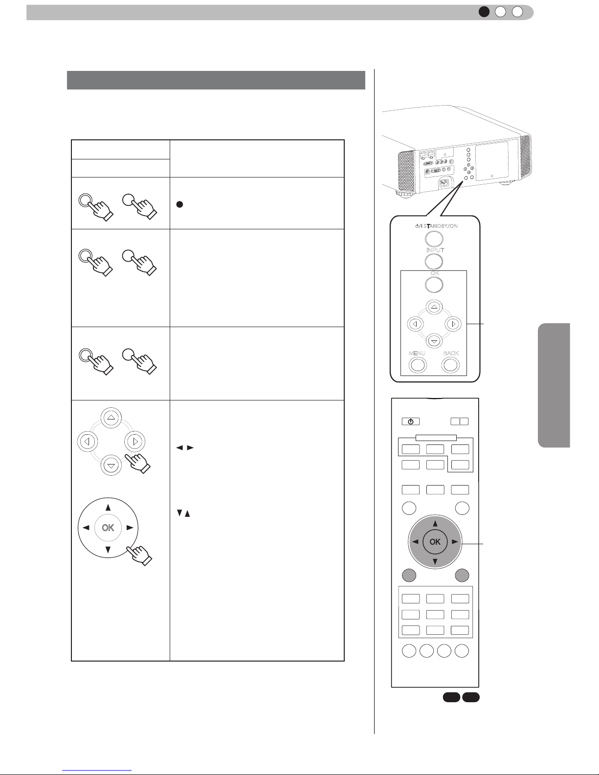
To turn on/off the power
To switch input
To select or conrm
Up button
Right button
Left button
Down button
To display the menu
To r
eturn to the previous menu
STANDBY/ON
MENU
BACK
INPUT
OK
⑤ Inlets
⑨ Lamp Cover
⑩ Operation panel
⑫ Power input
terminal
⑧ Input
terminal
⑤ Inlets
⑪ Light receiving section
of the remote control (rear)
■
Operation panel
Page 3

16
1
Getting started
Controls and features (continued)
Warnings and indications used during normal operation mode of this unit are displayed with the indicators
for [STAND BY / ON], [LAMP], [WARNING] at the front of this unit.
Meaning of the lighting gures:
Operation mode display
Displays the color and lighting/ashing of the [STAND BY / ON] indicator.
Criterion indication of the lamp replacement
Displays lighting/ashing of the [LAMP] indicator. Moreover, the [STAND BY / ON] indicator, which shows
the operation mode of this unit, is displayed as described above. (Reference page: 73)
The display the indicator lights.
They display ashing of the indicator.
STAND BY
Light on(Red)
Duringstandby
LAMP WARNING
STANDBY/ON
STAND BY
Light on(Green)
LAMP WARNING
STANDBY/ON
LAMP WARNING
STAND BY
Blinking(Red)
Duringcooldown
Whileactivatingthelamp
(about1minute)
STANDBY/ON
LAMP WARNING
STAND BY
Blinking(Green)
LAMP WARNING
Duringimageprojection
STANDBY/ON
All Off
When"Hide"issettoON
STANDBY/ON
LAMP Light on(orange)
Lamp replacement is near(When
accumulated lamp time has
exceeded 2900 hours)
STANDBY/ON
LAMP WARNING
LAMP Light on(orange)
Lamp has reached the end of life
(When accumulated lamp time has
exceeded 3000 hours)
STANDBY/ON
LAMP WARNING
Main body - About the indicator display
Page 4

17
Getting Started
ENGLISH
Warning display
You are informed of the contents of warning notices by the (repeated) displays of the [WARNING] and
[LAMP] indicators. Moreover, the [STAND BY / ON] indicator, which shows the operating mode of the unit,
is displayed simultaneously as described above.
Upon activation of the warning mode, the projection is interrupted at the same time for about 60 seconds
and the cooling fan is turne
d on. Please disconnect the power plug from the electric socket after the
cooling fan has stopped. Subsequently, please perform the following checks and take appropriate
countermeasures.
Lighting/flashing lights
status diagram
Blinking
Frequency
Content
Conrmation and
countermeasures
(
red
)
Abnormalities in the power
supply
●
Check that nothing is
blocking the air inlets.
●
Check that the external
temperature is normal.
Action
Leave the unit until it cools
down.
After that, turn on the power
again.
2 times Cooling fan stops
3 times
Internal temperature is too
high
4 times
External temperature is
too high
(
orange
) (
red
)
Sim
ultaneous
ashing
Abnormal electrical circuit
2 times
3 times
4 times
If something is wrong with
the automatic lens cover
●
Check that an impact shock
has not occurred during
operation.
●
Check that the lamp
unit and lamp cover are
correctly installed.
●
Check that nothing is
blocking the auto lens
cover.
Action
Turn on the power again.
Lamp does not light up
and unit is unable to
project
2 times
Lamp is turned off during
projection
3 times
Lamp cover is removed
Controls and features (continued)
Main body - Warning display and conrmation/response
STANDBY/ON
LAMP WARNING
STANDBY/ON
LAMP WARNING
STANDBY/ON
LAMP WARNING
If the warning indication is displayed again, please wait for the cooling fan stopped, then pull out the power
plug from the power outlet. Then call your authorized dealer for repair.
(
orange
) (
red
)
Mode
display
Mode
display
Mode
display
1 time
1 time
1 time
Page 5

18
1
Getting started
Controls and features (continued)
Main body - Input terminal
① HDMI 1 ② HDMI 2 ③ LAN
⑤ COMPONENT
⑧ TRIGGER
⑨ REMOTE
⑥ 3D SYNCHRO
⑦ PC
④ RS-232C
① HDMI 1 Terminal
You can connect a device equipped with HDMI
output, etc. It is tted to the M3 lock hole.
Screw hole depth 3mm. (Reference page: 26)
② HDMI 2 Terminal
You can connect a device equipped with HDMI
output, etc. It is tted to the M3 lock hole.
Screw hole depth 3mm. (Reference page: 26)
③ LAN terminal “RJ-45”
X7 X9
This is a LAN-terminal. If one connects an
external PC, it is possible to control this unit by
sending control commands. (Reference page:
30)
④ RS-232C terminal (male D-Sub 9
pin)
This is a RS-232C interface standard terminal.
If one connects an external PC, it is possible to
control this unit. (Reference page: 29)
⑤ COMPONENT terminal “RCAx3”
It is also used as input terminal for analog
RGB (G on Sync) signals, component (Y, Cb,
Cr) signals, DTV format (Y, Pb, Pr) signals. It
can also be connected with devices, which are
equipped with signal output, etc. (Reference
page: 27)
⑥ 3D SYNCHRO terminal
3D synchro emitter: it is connected to the PKEM1 (sold separately) when enjoying 3D video
contents. (Reference page: 28)
⑦ PC terminal “D-Sub 15 pin”
X7 X9
This is an input term used for Personal Computer
(PC) signals only (RGB video signals and sync
signals). Use to connect a computer display
output terminal, etc. (Reference page: 28)
⑧ TRIGGER terminal( )
DC power supply output terminal with DC12V,
100mA. It is used for output signals which control
the vacillating screen responding to the SCREEN
TRIGGER. Please note it can cause damage
to your equipment if the connection is done
incorrectly. (Tip = DC +12 V, Sleeve = GND)
(Reference Page: 29, 54)
⑨ REMOTE terminal to “Stereo mini
jack”
In case it is impossible to use the remote control
due to the installation of this unit’s dedicated
BOX or rear projection, one can set up an
external light receiving section. It is used to
connect this external receiver and this unit. There
is no such product as an external light receptor.
Therefore, please consult your authorized JVC
service center. (Reference page: 30)
X7 X9
X7 X9
Page 6

19
Getting Started
ENGLISH
Controls and features (continued)
■
Remote Control
How to insert batteries into the remote control
●
If the remote control has to be brought closer to the projector to operate, it means that the batteries are
wearing out.
When this happens, replace the batteries. Insert the batteries according to the
marks.
●
Be sure to insert the end rst.
●
If an error occurs when using the remote control, remove the batteries and wait for 5 minutes. Load the
batteries again and operate the remote control.
①
②
③
To turn on the power
To select input mode
(Reference page: 32)
To illuminate buttons on the remote
control for 7 second
To select or conrm
To return to the previous menu
(Reference page: 43)
To switch picture mode
Color Prole
Sequentially switched picture
adjust items, such as contrast and
brightness.The switching items are
not the same for different models, or
different picture modes.
To set gamma
To adjust color temperature
To display/close the menu
(Reference page: 43)
To hide the image
temporarily(Reference
page: 36)
Lens Aperture
To control lens
(Reference page: 32)
To turn off the power
Clear Motion Drive
BACK
HIDE
LIGHT
LENS AP.
C.M.D
PC
HDMI 1
STAND BY
ASPECT
HDMI 2
ANAMO
COMP.
LENS.
CONTROL
MENU
GAMMA
P.FILE
COLOR
ADJ.
PIC.
ON
FILM
NATURAL
STAGE 3D
USER1
USER2
THX
ANIME
CINEMA
PICTURE MODE
INPUT
TEMP
COLOR
To set the screen size
(Reference page: 34)
Anamorphic
Button: displays information
X7 X9
X3
X3
X3
INFO.
USER3
Button
Color space button
SPACE
COLOR
Page 7

20
Preparation
2
About installation
Important points concerning the installation
This unit is a precision device. Therefore, please refrain
from installation or use in the following locations.
Otherwise, it may cause re or malfunction.
• Dust, wet and humid locations.
• Sooty or cigarette smoke lled locations.
• On top of a carpet or bedding, or other soft surfaces.
• Locations with high temperatures - as located in direct
sunlight.
• Locations with high or low temperatures.
Permissible operating temperature range: +5 º to +35º .
Relative humidity range permissible for operating: 20%
~ 80% (non-condensing) .
Storage temperature tolerance: -10º to +60º.
• If the installation of the unit is done in a room with soot
and/or smoke over a longer period, even small amounts
of these substances will affect the device.This unit
cools its optical components, which produce a great
amount of heat, by sucking in air. If the optical circuits
get dirty, this might lead to malfunctions, like the video
images becoming darker or a deterioration of the color
development. Dirt sticking to the optical components
cannot be removed.
For better heat dissipation, please keep a minimum
distance between this unit and its surroundings as shown
in
the following illustration.
Moreover, please open the front of the unit. If there are
any objects in front of the exhaust port, the hot air will
ow back to the unit and heat it. The hot air owing out of
the unit might cause shadows on the screen (heat haze
phenomenon).
Moreover, when it is enclosed in a space as shown in the
following illustration, please make sure that the enclosed
interior has the same temperature as the outside. High
temperatures might lead to failure of the unit.
This unit uses a projection lamp, which will get hot when
in use. Please refrain from projecting in the following
circumstances.
Otherwise, it might cause re or malfunction.
• Projection while lying on its side.
Please avoid projection if the installation of the unit is
done at an excessive angle of more tha
n ± 30 °. It may
cause harm to the life of the lamp and color shading.
• Please avoid projection at a location where the air vents
or exhaust ports might get blocked.
Please choose a non-uniform cloth material for the screen.
If you choose something uniform, like something with a
checkered pattern, there might be interference with the
pixel array of the D-ILA components. One way to reduce
the interference pattern is to change the size of the screen,
so that it will not be so noticeable.
Inclination adjustment
for this unit
How to adjust the vertical angle
Height and inclination of the unit (0 ~ 5mm) can be
adjusted by rotating its feet. Lift the unit and adjust
the four feet.
Installation environment
Please be careful to perform
the installation at a certain
distance from walls and
other devices
Please be careful when using
Please read the following carefully before the installation of this unit.
Extend Contract
150 mm and above
300 mm
and above
200 mm
and above
300 mm
and above
150 mm
and above
Stand
CAUTION
CAUTION
CAUTION
Page 8

21
Preparation
ENGLISH
Installing the Projector and Screen
Set Angle
Shift
About installation (Continued)
While installing, please place this unit and the screen perpendicular to each other. Failing
to do so may increase trapezoidal distortion. (Reference page: 36, 52)
The angle range which can be set for this unit is ±30°.
■
Left/Right position
*
0% up/down position (center)
■
Up/Down position
*
0% left/right position (center)
Lens shift correlation chart:
●
Malfunctions may occur if the angle is not set within the above-mentioned range.
Approximately 34% (maximum) of the projected image
Approximately 34% (maximum) of the projected image
Approximately 80%
(maximum) of the projected
image
Approximately 80%
(maximum) of the
projected image
90
80
70
60
50
40
30
20
10
0 10 20
30 40
Horizontal lens shift
(%)
Vertical lens shift(%)
●
Maximum Up-Down shift varies with the amount of Left-Right shift.
Likewise, maximum Left-Right shift varies with the amount of UpDown shift.
●
The values on the chart are intended to act as a guide. Use them
for reference during installation.
30°
30°
30°
30°
Left-Right Shift(%)
0% 10% 20% 30% 34%
Up-Down Shift(%)
80% 66% 47% 18% 0%
Lens movability
range
■
Lens shift movement
range
Page 9

22
Preparation
2
About installation (Continued)
Fixation of the projector
Measures to prevent the unit from toppling or dropping should be taken for safety reasons and
accident prevention during emergencies including earthquakes.
When mounting this unit on a pedestal or ceiling, remove the 4 feet on the bottom surface and
use all the 4 screw holes (M5 screws) to mount.
Ceiling
■
Bottom Surface
Air inlets
4 locations
Precautions for Mounting
●
Special expertise and techniques are required for
mounting this unit. Be sure to ask your dealer or a
specialist to perform mounting.
●
Depth of the screw holes (screw length) is 23
mm. Use screws shorter than 23 mm but longer
than 13 mm.
Using other screws will result in
malfunctioning or cause the unit to drop.
●
When mounting to a pedestal, ensure
sufcient space (foot height of 10 mm or
higher) around the unit so that the air inlets
are not blocked.
●
Do not tilt this unit more than ±5 degrees
from side to side when using.
●
Regardless whether the unit is still under
guarantee, JVC is not liable for any product
damage caused by mounting the unit with non-
JVC ceiling ttings or when the environment is
not suitable for ceiling-mount.
●
When using the unit hanging from a ceiling,
pay attention to the surrounding temperature.
When a heater is in use, temperature around
the ceiling is higher than expected.
Page 10
23
Preparation
ENGLISH
About installation (Continued)
Determine the distance from the lens to the screen to achieve your desired screen size.
This unit uses a 2.0x power zoom lens for projection.
Screen Size and Projection Distance
■
Relationship Between Projection Screen Size and Projection Distance
Projection Screen Size
(Height, Width)
Aspect Ratio 16:9
A p pr o xi m at e P r oj e ct i on
Distance
W(Wide) to T(Tele)
140"
(Approx.1.7, 3.1m)
Approx.4.23 m to
Approx.8.60m
150"
(Approx.1.9, 3.3m)
Approx.4.53m to
Approx.9.22m
160"
(Approx.2.0, 3.5m)
Approx.4.84m to
Approx.9.84m
170"
(Approx.2.1, 3.8m)
Approx.5.14m to
Approx.10.45m
180"
(Approx.2.2, 4.0m)
Approx.5.45m to
Approx.11.07m
190"
(Approx.2.4, 4.2m)
Approx.5.75m to
Ap
prox.11.68m
200"
(Approx.2.5, 4.4m)
Approx.6.06m to
Approx.12.30m
Pr o jec tio n Sc r ee n
Size
(Height, Width)
Aspect Ratio 16:9
A p pr o x im at e Pr o j ec t io n
Distance
W(Wide) to T(Tele)
60
"
(
Approx.
0.7, 1.3m)
Approx.1.78m to
Approx.3.66m
70"
(Approx.0.9, 1.5m)
Approx.2.09m to Approx.4.28m
80"
(Approx.1.0, 1.8m)
Approx.2.40m to Approx.4.89m
90"
(Approx.1.1, 2.0m)
Approx.2.70m to Approx.5.51m
100"
(Approx.1.2, 2.2m)
Approx.3.0m to Approx.6.13m
110"
(Approx.1.4, 2.4m)
Approx.3.3m to Approx.6.75m
120"
(Approx.
1.5, 2.7m)
Approx.3.62m to Approx.7.36m
130"
(Approx.1.6, 2.9m)
Approx.3.92m to Approx.7.98m
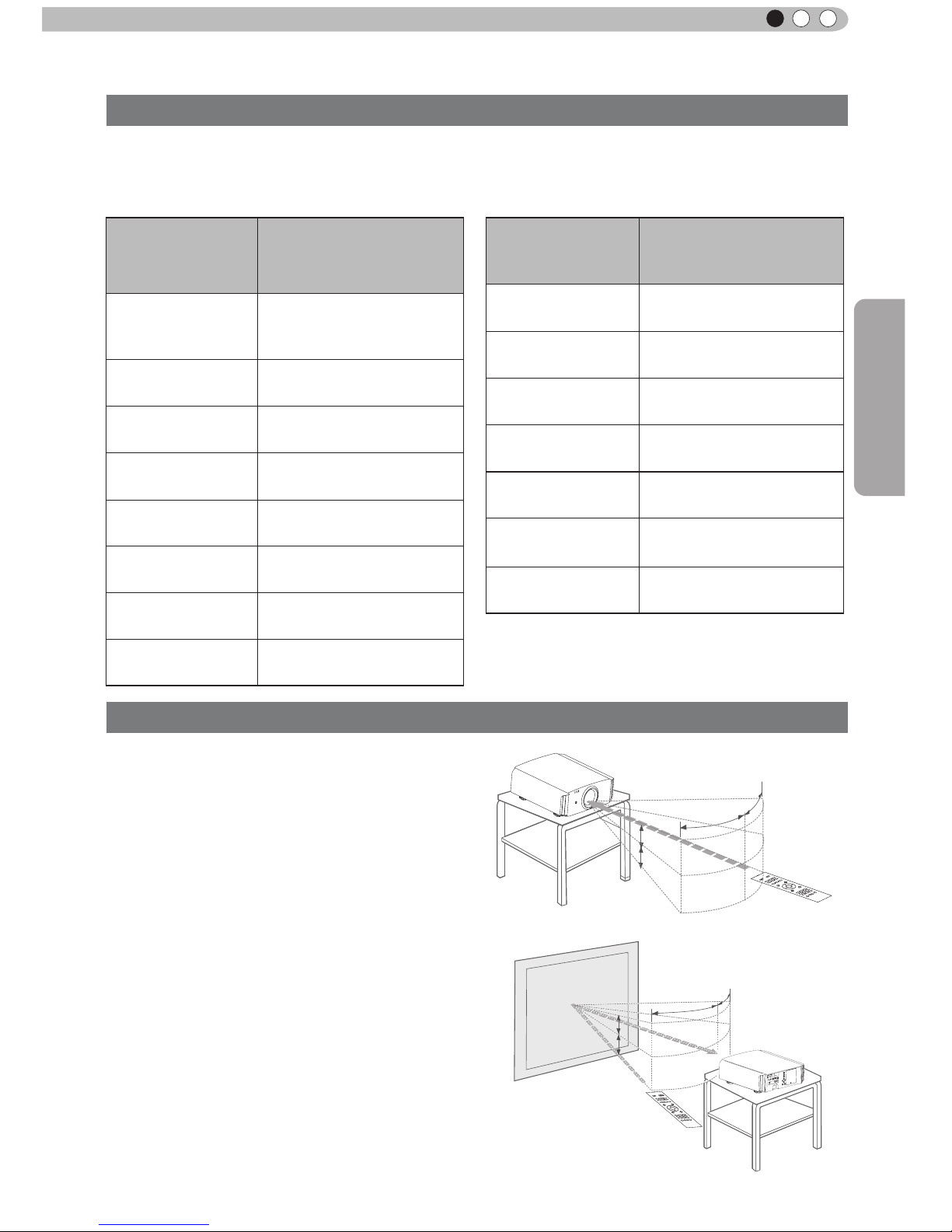
Effective Range of Remote Control Unit
■
When directing the remote control toward this
unit.
●
When aiming the remote control towards the
remote sensor on this unit, ensure that the
distance to the sensor in front or at the rear of
this unit is within 7 m.
●
If the remote control fails to work properly, move
closer to this unit.
■
When reecting off a screen
●
Ensure that the total of distance A between this
unit and screen and distance B between remote
control and screen is within 7 m.
●
As the efciency of signals reected from the
remote control unit differ with the type of screen
used, operable distance may decrease.
30°
30°
20°
20°
30°
30°
20°
20°
A
B
This unit
This unit
Remote control
Screen
Remote control
Page 11

24
Preparation
2
About the connection
Types of possible input signals (PC compatible)
●
HDMI
No.
Designation
Resolution
fh
[kHz]
fv
[Hz]
dot CLK
[MHz]
Total No.
of dots
[dot]
Total No.
of lines
[line]
No. of
effective
dots
[dot]
No. of
effective
lines [line]
1
VGA
60 640 X 480 31.500 60.000 25.200 800 525 640 480
2
VGA
59.94 640 X 480 31.469 59.940 25.175 800 525 640 480
3
SVGA
60 800 X 600 37.879 60.317 40.000 1,056 628 800 600
4
XGA
60 1024 X 768 48.363 60.004 65.000 1,344 806 1,024 768
5
WXGA
60 1280 X 768 47.760 60.000 79.998 1,675 796 1,280 768
6
WXGA
+60 1440 X 900 55.919 59.999 106.470 1,904 932 1,440 900
7
SXGA
60 1280 X 1024 63.981 60.020 108.000 1,688 1,066 1,280 1,024
8
WSXGA
+60 1680 X 1050 65.222 60.002 147.140 2,256 1,087 1,680 1,050
9
WUXGA
60 1920 X 1200 74.038 59.95 154.000 2,080 1,235 1,920 1,200
●
PC (D-sub 3-lines 15 pins)
No.
Designation
Resolution
fh
[kHz]
fv
[Hz]
dot CLK
[MHz]
Total No.
of dots
[dot]
Total
No. of
lines
[line]
No. of
effective
dots
[dot]
No. of
effective
lines [line]
1
VGA
60 640 X 480 31.500 60.000 25.175 800 525 640 480
2
VGA
72 640 X 480 37.900 72.000 31.500 832 520 640 480
3
VGA
75 640 X 480 37.500 75.000 31.500 840 500 640 480
4
VGA
85 640 X 480 43.300 85.000 36.000 832 509 640 480
5
SVGA
56 800 X 600 35.200 56.000 36.000 1024 625 800 600
6
SVGA
60 800 X 600 37.900 60.000 40.000 1056 628 800 600
7
SVGA
72 800 X 600 48.100 72.000 50.000 1040 666 800 600
8
SVGA
75 800 X 600 46.900 75.000 49.500 1056 625 800 600
9
SVGA
85 800 X 600 53.700 85.000 56.250 1048 631 800 600
10
XGA
60 1024 X 768 48.400 60.000 65.000 1344 806 1024 768
11
XGA
70 1024 X 768 56.500 70.000 75.000 1328 806 1024 768
12
XGA
75 1024 X 768 60.000 75.000 75.750 1312 800 1024 768
13
XGA
85 1024 X 768 68.700 85.000 94.500 1376 808 1024 768
14
WXGA
60 1280 X 768 47.760 60.000 79.998 1675 796 1280 768
15
WXGA+
60 1440 X 900 55.919 59.999 106.470 1904 932 1440 900
16
SXGA
60 1280 X 1024 64.000 60.000 108.000 1688 1066 1280 1024
17
SXGA+
60 1400 X 1050 63.981 60.020 108.000 1688 1066 1400 1050
18
WSXGA+
60 1680 X 1050 65.222
60.002 147.140 2256 1087 1680 1050
19 1920x1080 60 1920 X 1080 67.500 60.00 148.500 2200 1125 1920 1080
20
MAC
13" 640 X 480 35.000 66.667 30.240 864 525 640 480
21
MAC
16" 832 X 624 49.107 75.087 55.000 1120 654 832 624
22
MAC
19" 1024 X 768 60.241 74.927 80.000 1328 804 1024 768
Page 12
25
Preparation
ENGLISH
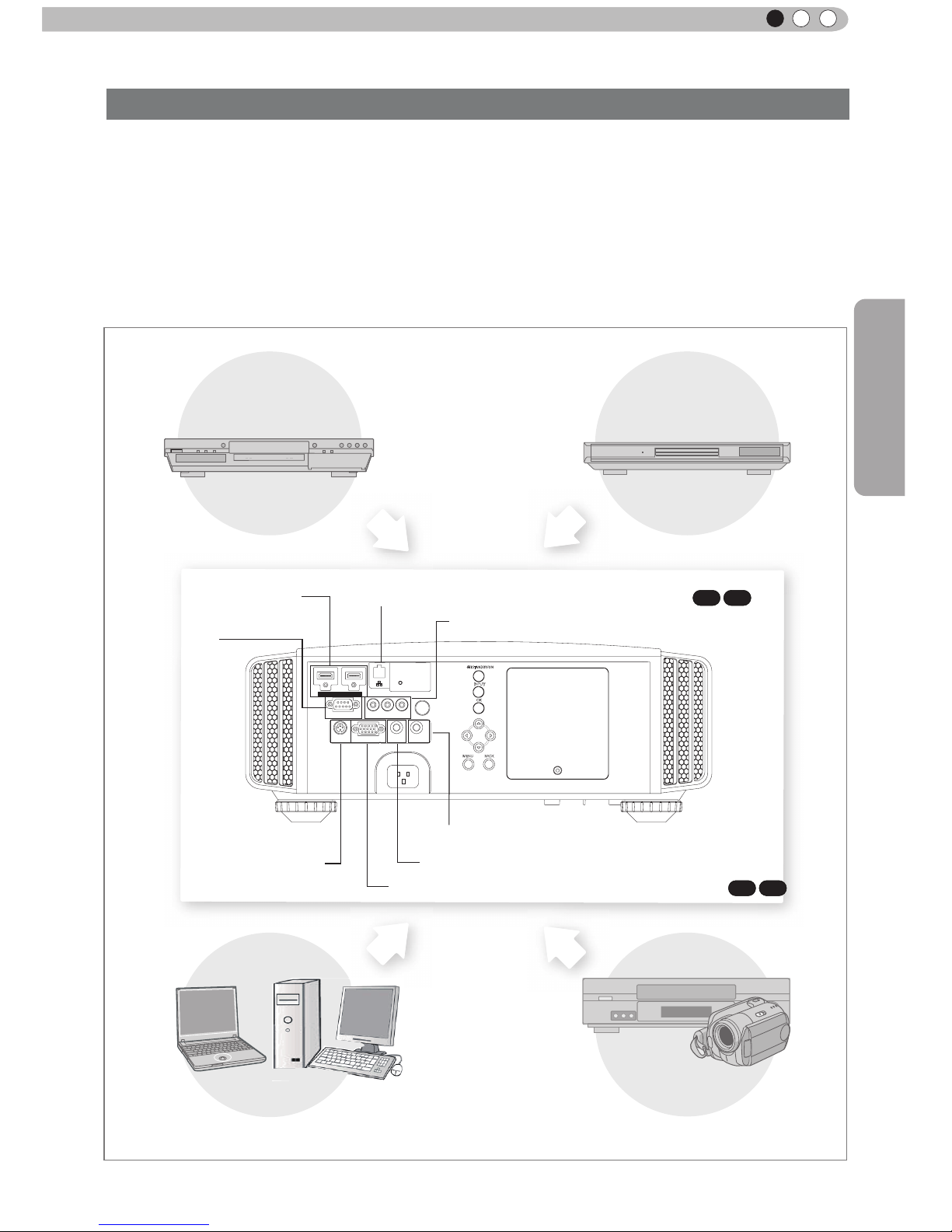
About the connection (Continued)
●
Do not turn on the power until connection is complete.
●
The connection procedures differ according to the device used. For details, refer to the instruction
manual of the device to be connected.
●
This device is used for image projection. Connect to an audio output device such as amplier and
speaker for audio output from the connected device.
●
The images may not be displayed depending on the devices and cables to be connected.
For HDMI cable (sold separately), only use one that is HDMI-approved.
●
It may not be possible to connect to this unit depending on the dimension of the connector cover of the
cables to be connected.
1 HDMI 2
RS-232-C
3D
C
R/PR CB/PB Y
SYNCHRO
PC
TRIGGER
REMOTE
CONTROL
STANDBY/ON
MENU
BACK
INPUT
OK
To connect via HDMI
terminal
(Reference page: 26)
Connection to the unit
To connect via video terminal
(Reference page: 27)
Connection by LAN terminal (Reference page: 30)
X7 X9
To connect via PC terminal
(Reference page: 28)
X7 X9
Connection by 3D SYNCHRO
terminal (Reference page: 28)
Connection by REMOTE terminal (Reference page: 30)
To connect RS232C terminal
(Reference
page: 29)
PC
VCR and
camcorder
BD/DVD Recorder BD/DVD Player
To connect via Trigger terminal
(Reference page: 29)
Page 13
26
Preparation
2
About the connection (Continued)
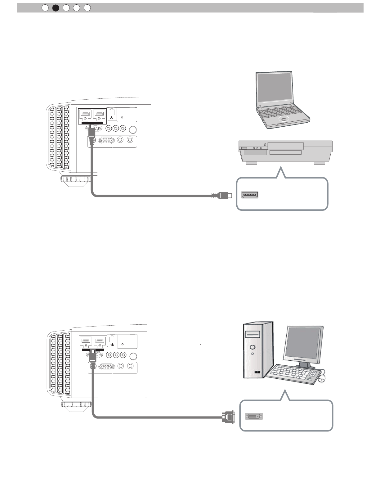
■
Connecting via HDMI Cable
■
Connecting via HDMI-DVI Conversion Cable
1 HDMI 2
RS-232-C
3D
C
R/PRCB/PB
Y
SYNCHRO
PC
TRIGGER
REMOTE
CONTROL
STANDBY/ON
MENU
BACK
INPUT
OK
1 HDMI 2
RS-232-C
3D
C
R/PRCB/PB
Y
SYNCHRO
PC
TRIGGER
REMOTE
CONTROL
STANDBY/ON
MENU
BACK
INPUT
OK
This unit
This unit
BD/DVD recorder
HDMI cable (sold separately)
HDMI output terminal
Notebook PC
●
If noise is produced, take PCs (Notebook PC) away from this unit.
●
For a transmission bandwidth in compliance with the HDMI standard, a 340MHz cable is recommended.
In case a cable is used for transmission bandwidth of 75MHz, it is recommended to choose 1080i or
less for the transmitting equipment.
●
If the video is not displayed, try to reduce the length of the cable or lowering the resolution of the video
transmitting equipment.
●
If noise is produced, take PCs (desktop computer) away from this unit.
●
If the video is not displayed, try to reduce the length of the cable or lowering the resolution of the video
transmitting equipment.
HDMI-DVI conversion cable
(sold separately)
DVI output terminal
Desktop computer
HDMI 1 input terminal
HDMI 2 input terminal
HDMI 1 input terminal
HDMI 2 input terminal
Page 14
27
Preparation
ENGLISH
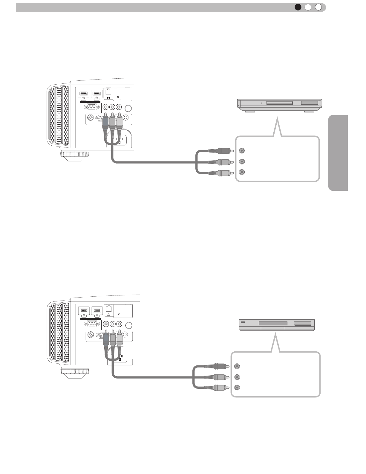
About the connection (Continued)
1 HDMI 2
RS-232-C
3D
C
R/PR CB/PB Y
SYNCHRO
PC
TRIGGER
REMOTE
CONTROL
STANDBY/ON
MENU BACK
INPUT
OK
C
BD/DVD player
Component video output terminals
Y (green)
C
R/PR
(red)
C
B/PB
(blue)
●
Set “COMP.” in the setting menu to “Y Pb/Cb Pr/Cr”.
(Reference page: 52)
This unit
To component video input terminals
Component video cable
(sold separately)
■
Connecting via RGB Video Cable
●
Set “COMP.” in the setting menu to “RGB”. (Reference page: 52)
●
For information on compatible input signals, see “Specications”.(Reference page: 73)
1 HDMI 2
RS-232-C
3D
C
R/PR CB/PB Y
SYNCHRO
PC
TRIGGER
REMOTE
CONTROL
STANDBY/ON
MENU
BACK
INPUT
OK
This unit
Device equipped with
RGB output
RGB video cable
(sold separately)
RGB video output terminals
R(Red)
B(Blue)
G(Green)
(Includes sync
signals)
To RGB video input terminals
■
Connecting via Component Video Cable
Page 15

28
Preparation
2
■
Connecting via PC Cable
X7 X9
About the connection (Continued)
1 HDMI 2
RS-232-C
3D
C
R/PRCB/PB
Y
SYNCHRO
PC
TRIGGER
REMOTE
CONTROL
STANDBY/ON
MENU
BACK
INPUT
OK
This unit
●
For information on supported input signals, please refer to “Specications
”.
(Reference page: 73)
PC cable(sold separately
)
To PC input terminal
VGA output terminal
Notebook PC
■
Connected by a 3D SYNCHRO terminal
1 HDMI 2
RS-232-C
3D
C
R/PRCB/PB
Y
SYNCHRO
PC
TRIGGER
REMOTE
CONTROL
STANDBY/ON
MENU
BACK
INPUT
OK
This unit
●
3D synchro emitter: This is a dedicated terminal for PK-EM1 (sold separately).
●
3D glasses (PK-AG1-B) is an optional device, and is not included in the 3D synchro emitter.
Before you watch 3D video images, make sure to read "3D description of the system"
(Reference page 57 to 59).
3D synchro emitter
3D-glasses
CAUTION
Page 16

29
Preparation
ENGLISH
About the connection (Continued)
■
Connecting via Trigger Cable
1 HDMI 2
RS-232-C
3D
C
R/PRCB/PB
Y
SYNCHRO
PC
TRIGGER
REMOTE
CONTROL
STANDBY/ON
MENU
BACK
INPUT
OK
This unit
●
Do not supply the power to the other devices.
●
Do not connect audio terminals of the other devices such as headphones etc. Otherwise, this may
cause a malfunction of the other devices or injury.
●
Using beyond the rated value will cause malfunction.
● Exercise adequate caution to prevent short circuit as the trigger terminal outputs a voltage of 12V.
●
The default is set to "No output". Please set it under the item "Trigger" of menu [5] "Function" (Reference
page: 54).
Screen
Trigger cable
(sold separately)
Trigger input terminal
(Φ3.5)
1 HDMI 2
3D
C
R/PRCB/PB
Y
SYNCHRO
PC
TRIGGER
REMOTE
CONTROL
STANDBY/ON
MENU
BACK
INPUT
OK
■
Connected by RS-232C connection cable
This unit
RS-232C
terminal
RS-232C connection cable (sold separately)
To Trigger output terminal
CAUTION
Page 17

30
Preparation
2
About the connection (Continued)
■
Connected by LAN terminal
X7 X9
1 HDMI 2
RS-232-C
3D
C
R/PR CB/PB Y
SYNCHRO
PC
TRIGGER
REMOTE
CONTROL
STANDBY/ON
MENU
BACK
INPUT
OK
This unit
●
The network is used to control the unit. It is not used for transmission of the video signal.
●
Please contact your network administrator for questions concerning the network connection.
Network
HUB
Server
1 HDMI 2
RS-232-C
3D
C
R/PR CB/PB Y
SYNCHRO
PC
TRIGGER
REMOTE
CONTROL
STANDBY/ON
MENU
BACK
INPUT
OK
■
Connected by a REMOTE terminal
This unit
External infrared sensor
(sold separately)
●
For an external infrared sensor and connecting cable, please contact your dealer or a JVC service
center.
connection cable(sold separately)
connection cable
(sold separately)
Page 18

31
Preparation
ENGLISH
About the connection (Continued)
Connection of the power cord (provided)
Once you have connected the equipment, connect the projector power cord.
1 HDMI 2
RS-232-C
3D
C
R/PRCB/PB
Y
SYNCHRO
PC
TRIGGER
REMOTE
CONTROL
STANDBY/ON
MENU
BACK
INPUT
OK
Power Cord
(Supplied)
1
2
1 Connect the power cord supplied with the
unit power input terminal
2 Connect to the power outlet
● As the amount of electrical energy for this unit is large, please connect it directly into
the wall outlet.
● When you are not using the equipment, please unplug the power cord.
● Connect it only with the provided power cord.
● Do not use voltage other than the indicated power voltage.
● Do not damage, break or modify the power cord. Moreover, the power cord will be
damaged if you place it under heavy objects, heat or pull it.
● Do not unplug with wet hands.
Be carful to avoid re and electric shocks
CAUTION
Page 19

32
Operation
3
Basic Operation
Basic operation procedures
WARNING
LAMP
STANDBY/ON
Once you have nished the basic setup, the unit can normally be
used just with the following operations.
1
2
3
Turn on power source
ON
STANDBY/ON
Light on (Green)
●
You can also press the
button on the unit to turn
on the power
. (Reference page: 15)
●
The lens cover will be opened.
Choose the projected image
1
Select input mode
●
You can also select the input mode by pressing the
INPUT
button on the unit. (Reference page: 15)
HDMI 1
HDMI 2 COMP. PC
2
Play back the selected device
Adjust the zoom (screen size)
BACK
Back
Operate
Select
Exit
MENU
Zoom
Lens Control
LENS
Adjust accordingly
by pressing the up/
down buttons
4
Adjust the focus (focal point)
Adjust accordingly
by pressing the
up/down buttons
BACK
Back
Operate
Select
Exit
MENU
Focus
Lens Control
LENS
BACK
HIDE
LIGHT
LENS AP.
C.M.D
PC
HDMI 1
STAND BY
ASPECT
HDMI 2
ANAMO
COMP
.
LENS.
CONTROL
MENU
GAMMA
P.FILE
COLOR
ADJ.
PIC.
ON
FILM
NATURAL
STAGE 3D
USER1
USER2
THX
ANIME
CINEMA
PICTURE MODE
INPUT
TEMP
COLOR
6
4
2
5
3
1
X7 X9
Page 20

Operation
33
ENGLISH
5
Adjust the shift (image position)
Adjust accordingly
by pressing the
up/down buttons
BACK
Back
Operate
Select
Shift
Lens Control
●
After adjusting the image position, it may be necessary to
select “Pixel Adjust” from the Settings menu “Installation”.
(Reference page:53)
●
Every time the
LENS
button is pressed, the adjustment
item will be switched among “Focus”, “Zoom” and “Shift”.
OK
It can also be switched with the button.
)RFXV =RRP
6KLIW
LENS
STAND BY
STAND BY
STAND BY/ON
STAND BY/ON
Blinking (Red Lamp)
Light on (Red Lamp)
While a confirmation screen is displayed
Cool Down mode
6
Turn off power source
●
When power off, the lens cover will be closed.
●
The power cannot be turned off within approximately 90
seconds after it has been turned on. Start operation only
after 90 seconds time.
●
You can also press the
button on the unit to turn off
the power. (
Reference page: 15
)
●
Pull out the power plug when the unit will not be used for a
prolonged time.
About Cool Down
mode
MEMO
●
The Cool Down mode is a
function to cool down the lamp
for approximately 60 seconds
after projection is complete.
This function prevents the
internal parts of the unit from
deformation or damage due to
overheating of the lamp. It also
prevents lamp blowout and
premature shortening of lamp
life.
●
During Cool Down mode, the
[STANDBY/ON] indicator blinks
in red.
●
After the Cool Down mode is
complete, the unit automatically
returns to standby mode.
●
Do not pull out the power plug
during Cool Down mode. This
may shorten the lamp life and
cause a malfunction.
LENS
Page 21

34
Operation
3
Basic Operation (continued)
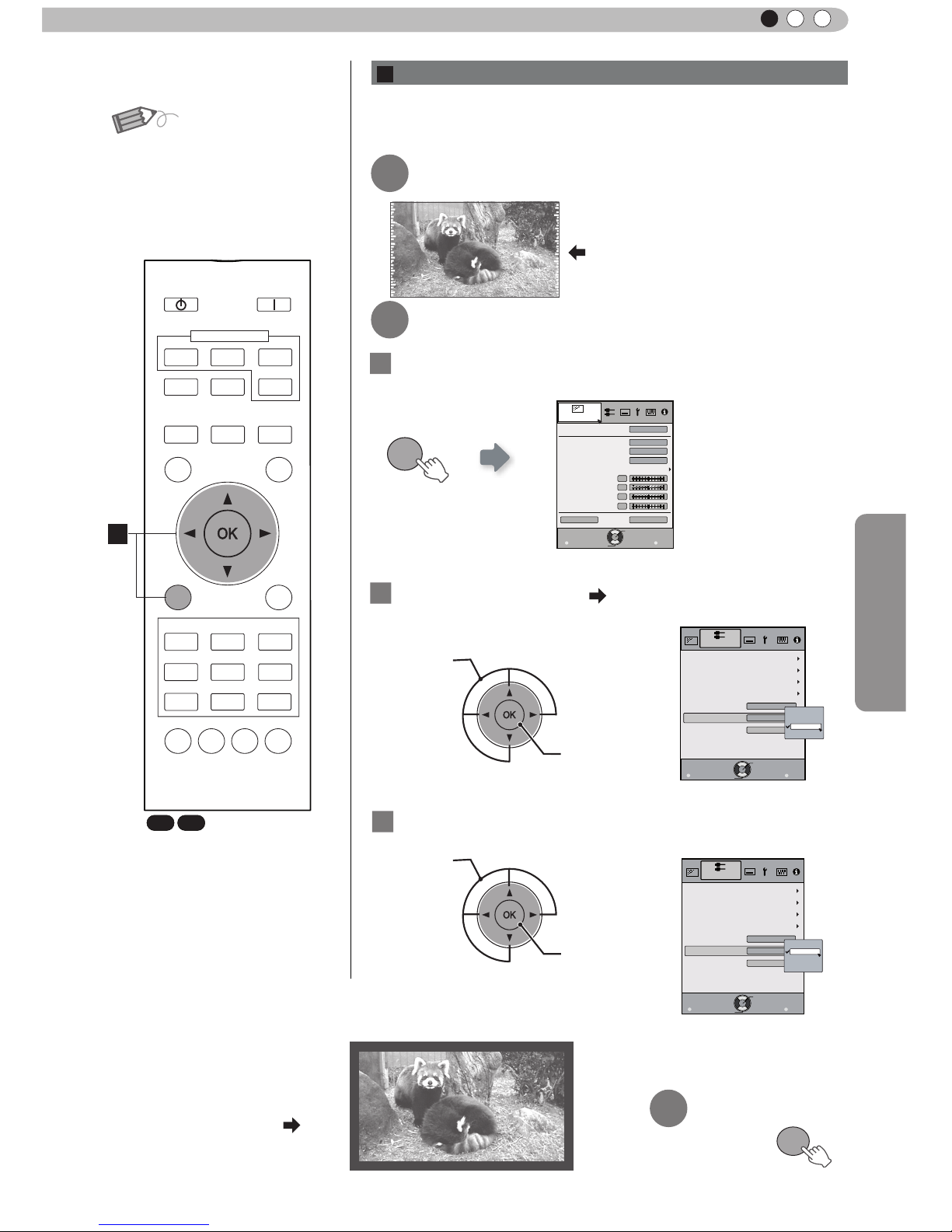
Frequently used useful functions
Setting the Screen Size
Masking the Surrounding Area of an Image
Temporary turning-off of the video
Adjustment of the keystone correction
The projected image can be set to a most appropriate screen
size (aspect ratio).
● The screen size can also be set from
“
Aspect(Video)” of the
setting menu. (Reference page: 50)
● When PC signals are input, the
“
Aspect(Computer)” setting will be
available instead. (Reference page: 50)
■
Input Image and Projected Image by Different Screen
Size
Screen Size
4:3
16:9
Zoom
Input Image
SDTV(4:3)
Aspect Ratio:Same
Most appropriate
screen size
Aspect Ratio:
Landscape
Image is stretched
horizontally
Aspect Ratio:Same
Top and bottom of
the image are
missing
SDTV(4:3)
Image recorded in
landscape (black
bands on top and
bottom) of DVD
software
Aspect Ratio:Same
Small image is
projected
Aspect Ratio:
Landscape
Image is stretched
horizontally
Aspect Ratio:Same
Most appropriate
screen size
● Depending on the input image, selecting
“
4:3” may result in a
vertically stretched image, while selecting “16:9” provides you
with the most appropriate screen size.
● When there is 3D signal input, the ratio is xed to
“
16:9”.
ASPECT
4:3 16:9 Zoom
You can change the screen size of the projected image or
hide the surrounding area of an image for which quality at the
outer area has deteriorated.
A
Setting the Screen Size
X7 X9
BACK
HIDE
LIGHT
LENS AP.
C.M.D
PC
HDMI 1
STAND BY
ASPECT
HDMI 2
ANAMO
COMP.
LENS.
CONTROL
MENU
GAMMA
P.FILE
COLOR
ADJ.
PIC.
ON
FILM
NATURAL
STAGE 3D
USER1
USER2
THX
ANIME
CINEMA
PICTURE MODE
INPUT
TEMP
COLOR
A
A
B
C
D
Page 22
Operation
35
ENGLISH
MEMO
●
Maski ng is av ailabl e only
when high definition images
are input.
2
Mask the image
② Confirm
MENU
Picture Adjust
Reset
Advanced
Exit
MENU
BACK
Back
Select
Operate
Color Temp.
Gamma
Film Tone
Contrast
Brightness
Color
Tint
0
0
0
0
Color Profile
Picture Mode
Film
Film1
Xenon1
Film1
1
Display the setting menu
2
Select “Input Signal” “Mask
”
① Select
② Confirm
Exit
MENU
BACK
Back
Select
Operate
Aspect (Video)
Progressive
HDMI
COMP.
Auto
PC
Picture Position
16:9
Off
Mask
2.5%
5%
Off
Custom
Input Signal
3
Set a mask value
① Select
Exit
MENU
BACK
Back
Select
Operate
Aspect (Video)
Progressive
HDMI
COMP.
Auto
PC
Picture Position
16:9
5%
5%
Mask
2.5%
5%
Off
Custom
Input Signal
Example:
When the “Mask” value is
changed from “Off”
“5%”
3
To end
MENU
Images for which quality at the outer area has deteriorated
can be projected by masking (hiding) the surrounding area of
the projected image.
1
Image for which quality at the outer
area has deteriorated.
Project the image
B
Masking the Surrounding Area of an Image
BACK
HIDE
LIGHT
LENS AP.
C.M.D
PC
HDMI 1
STAND BY
ASPECT
HDMI 2
ANAMO
COMP.
LENS.
CONTROL
MENU
GAMMA
P.FILE
COLOR
ADJ.
PIC.
ON
FILM
NATURAL
STAGE 3D
USER1
USER2
THX
ANIME
CINEMA
PICTURE MODE
INPUT
TEMP
COLOR
B
X7 X9
Page 23

36
Operation
3
MENU
Picture Adjust
Reset
Advanced
Exit
MENU
BACK
Back
Select
Operate
Color Temp.
Gamma
Film Tone
Contrast
Brightness
Color
Tint
0
0
0
0
Color Profile
Picture Mode
Film
Film1
Xenon1
Film1
1
Display the setting menu
3
Adjusts keystone correction
If one presses the cursor (vertical and horizontal arrows) in the
keystone correction mode, the keystone distortion can be adjusted.
4
Exit
Basic Operation (continued)
You can hide the image temporarily.
HIDE
Green light blinks
when the image is
hidden.
●
Press the
HIDE
button again to display image.
●
The power cannot be turned off when the image is temporarily
hidden.
D
Adjustment of the keystone correction
C
Temporary turning-off of the video
In regards to the projection plane, any occurring keystone distortion
is adjusted in case the installation location is inclined.
2
Select “Installation” “Keystone
”
① Selec
② Confirm
Exit
MENU
BACK
Back
Select
Operate
Pixel Adjust
Installation
Lens Control
Anamorphic
Screen Adjust
Black Level
Installation Style
Front
Off
Keystone
X7 X9
BACK
HIDE
LIGHT
LENS AP.
C.M.D
PC
HDMI 1
STAND BY
ASPECT
HDMI 2
ANAMO
COMP.
LENS.
CONTROL
MENU
GAMMA
P.FILE
COLOR
ADJ.
PIC.
ON
FILM
NATURAL
STAGE 3D
USER1
USER2
THX
ANIME
CINEMA
PICTURE MODE
INPUT
TEMP
COLOR
C
D
Adjust horizontal distortion with the
cursors for left and right.
Adjust vertical
distortion with
the cursors for
up and down.
●
When there is a 3D input
signal, adjustment is not
possible. Moreover, even if
the keystone correction is
adjusted, keystone correction
is removed when there is a 3D
input signal.
MENU
Page 24

Operation
37
ENGLISH
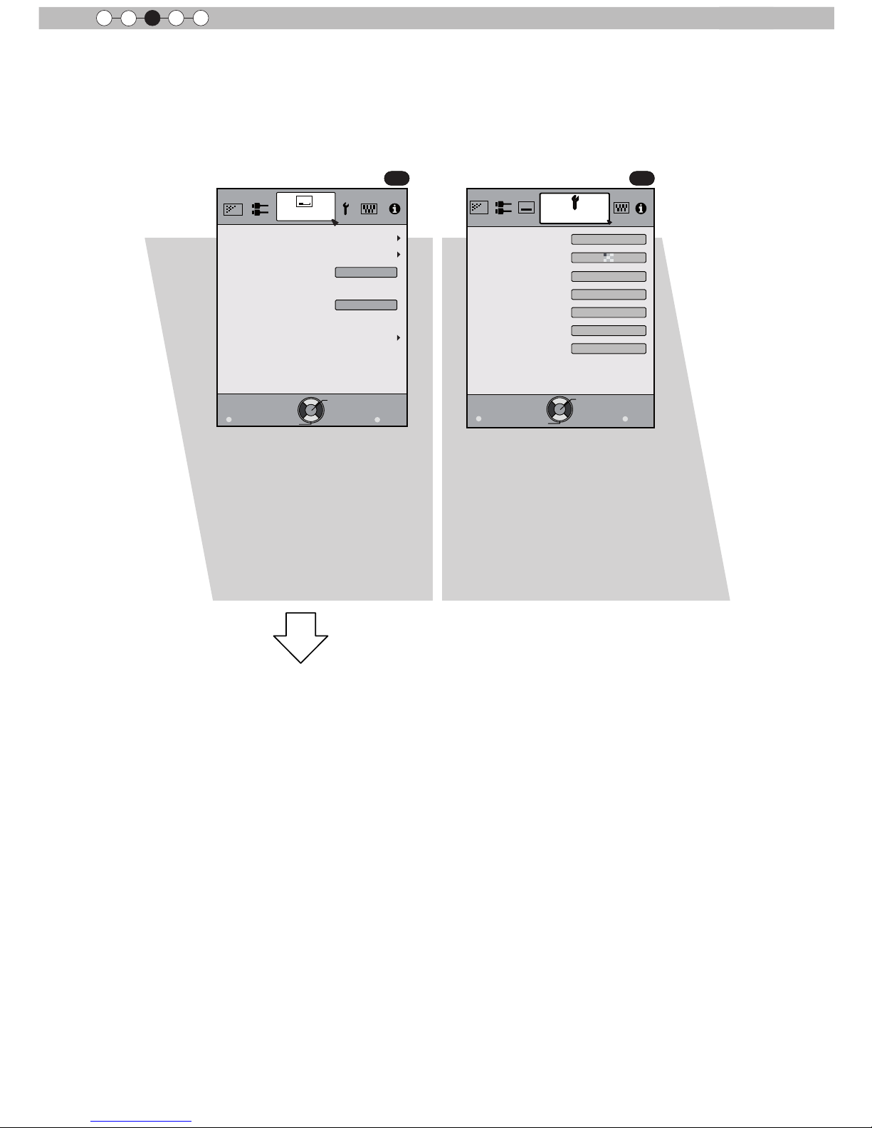
Adjustments and settings in the menu
The Menu of this unit is organized as follows. As this is only a brief guideline, items, which might not be
displayed due to certain settings, are still displayed in the illustration. Moreover, in regard to
COM
, it shows
countermeasures for all kinds of devices, but there the values for setting and adjustment might be different.
See “Description of menu items” (Reference: Since 45 and following) for details. It can be moved to
subscreens used for adjustment, even for items that do not feature submenus.
Structure of the menu hierarchy (summary)
To “[2] Layers and
organization of the input
signal submenu”
To “[1] Layers and
organization of the picture
quality submenu
”
Picture Adjust
Reset
Advanced
Exit
MENU
BACK
Back
Select
Operate
Color Temp.
Gamma
Film Tone
Contrast
Brightness
Color
Tint
0
0
0
0
Color Profile
Picture Mode
Film
Film1
Xenon1
Film1
Picture Adjust
Reset
Exit
MENU
BACK
Back
Select
Operate
Color Temp.
Gamma
Advanced
Contrast
Brightness
Color
Tint
0
0
0
0
Picture Mode
Natural
6500K
Normal
Exit
MENU
BACK
Back
Select
Operate
Aspect(Video)
Progressive
HDMI
COMP.
Mask
Auto
PC
Picture Position
16:9
Off
Input Signal
Exit
MENU
BACK
Back
Select
Operate
Aspect(Video)
Progressive
HDMI
COMP.
Mask
Auto
Picture Position
16:9
Off
Input Signal
X7 X9
X7 X9
X3 X3
(*) Apart from “Film”,
“Brightness/darkness
correction” is displayed in
the “Picture Mode”.
(*) When there is a PC
signal input, “Aspect
(PC)” is displayed.
(*)
(*)
Continue to
the next
[2] Input signal
[1] Picture Adjust
(*) When there is a PC signal
input, “Aspect (PC)” is
displayed.
(*)
Page 25
38
Operation
3
Adjustments and settings in the menu (continued)
Exit
MENU
BACK
Back
Select
Operate
Pixel Adjust
Installation
Lens Control
Keystone
Anamorphic
Screen Adjust
Black Level
Installation Style
Front
Off
Exit
MENU
BACK
Back
Select
Operate
Display Setup
Back Color
Menu Display
Menu Position
On
Line Display
5sec
Source Display
On
Logo
On
Language
English
Black
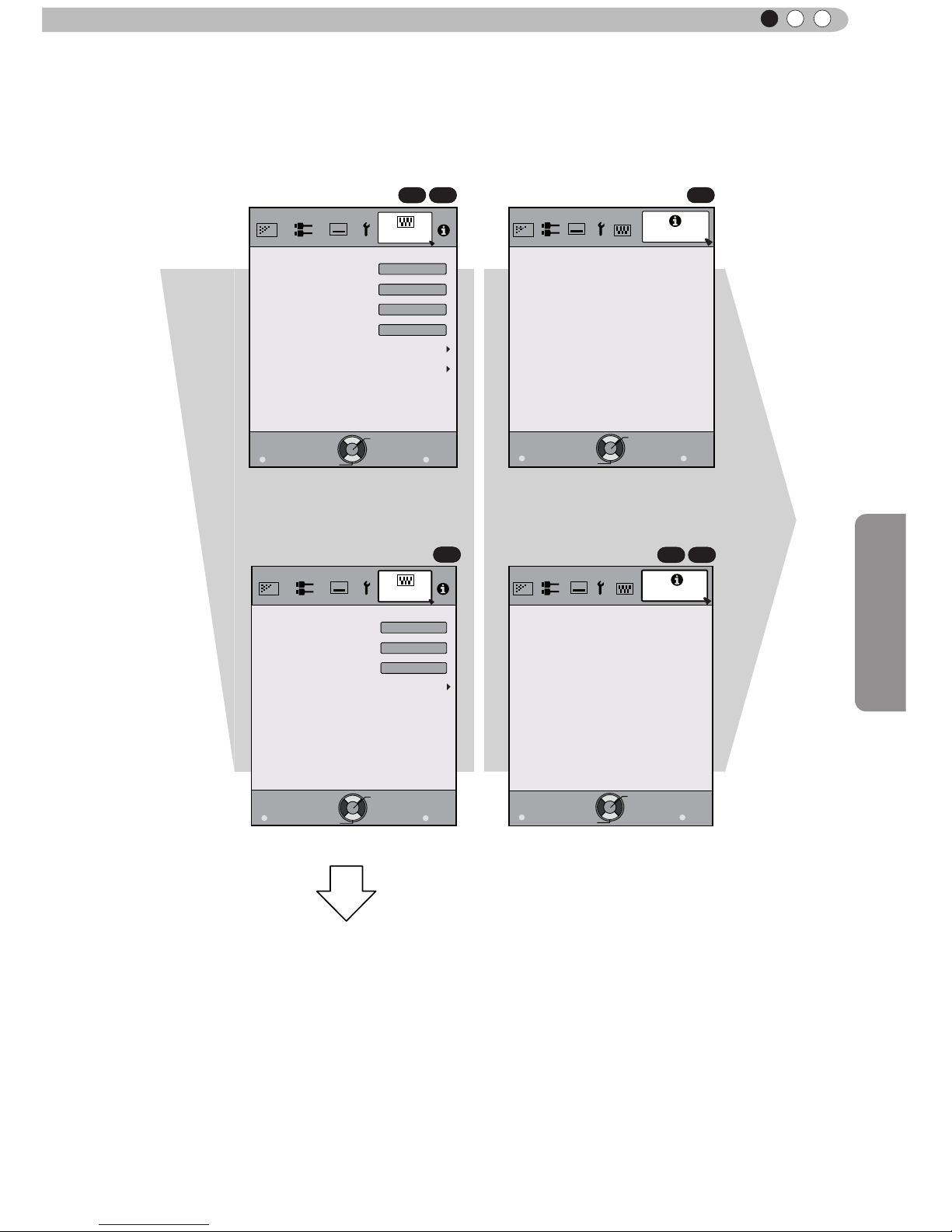
[4] Display settings[3] Installation
To “[3] Layers and
organization of the
installation submenu”
Continue
to the next
Continued from
the previous page
COM COM
Page 26
Operation
39
ENGLISH
Adjustments and settings in the menu (continued)
Exit
MENU
BACK
Back
Select
Operate
Trigger
Off Timer
Communication Terminal
Network
Lamp Reset
High Altitude Mode
LAN
Off
Off
Off
Function
Exit
MENU
BACK
Back
Select
Operate
Trigger
Off Timer
Lamp Reset
High Altitude Mode
Off
Off
Off
Function
Exit
MENU
BACK
Back
Select
Operate
160H
HDMI-2
1080p60
10bit
Input
Source
Deep Color
Lamp Time
Information
:
:
:
:
Exit
MENU
BACK
Back
Select
Operate
Lamp Time
Deep Color
160H
PC
1920X1080
Information
Resolution
67.50kHz
H Frequency
60.0Hz
V Frequency
Input
:
:
:
:
:
:
8bit
To “[5] Layers and
organization of the function
submenu”
[6] Information[5] Function
X7 X9
X7 X9
X3
For PC signal input
COM
Continued
from the
previous
page
Page 27

40
Operation
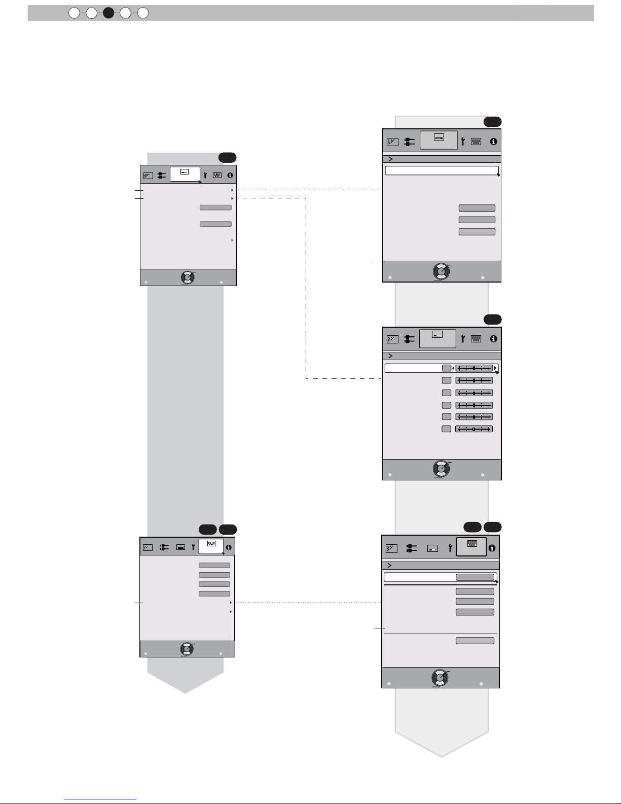
3
[1] Layers and organization of the picture adjust submenu
Adjustments and settings in the menu (continued)
>
Color Temp.
Gain Red
Gain Green
Gain Blue
Offset Red
Offset Green
Offset Blue
Preset
Custom1
Custom2
Custom3
Picture Adjust
Xenon1
Exit
MENU
BACK
Back
Select
Operate
Reset
0
0
0
0
0
0
5500K
6000K
6500K
7000K
7500K
8000K
8500K
9000K
9500K
Xenon1
Xenon2
Xenon3
>
Color Temp.
Gain Red
Gain Green
Gain Blue
Offset Red
Offset Green
Offset Blue
Preset
Custom1
Custom2
Custom3
Picture Adjust
6500K
Exit
MENU
BACK
Back
Select
Operate
Reset
0
0
0
0
0
0
6500K
5500K
6000K
7000K
7500K
8000K
8500K
9000K
9500K
High Brightness
6500K
Picture Adjust
Reset
Advanced
Exit
MENU
BACK
Back
Select
Operate
Color Temp.
Gamma
Film Tone
Contrast
Brightness
Color
Tint
0
0
0
0
Color Profile
Picture Mode
Film
Film1
Xenon1
Film1
Picture Adjust
Reset
Exit
MENU
BACK
Back
Select
Operate
Color Temp.
Gamma
Advanced
Contrast
Brightness
Color
Tint
0
0
0
0
Picture Mode
Natural
6500K
Normal
Picture Adjust
Exit
MENU
BACK
Back
Select
Operate
>
Advanced
0
Lens Aperture
CMD Demo
Clear Motion Drive
Color Management
Custom Gamma
NR
Lamp Power
Sharpness
Off
Off
Normal
Picture Adjust
Exit
MENU
BACK
Back
Select
Operate
>
Advanced
0
Lens Aperture
CMD Demo
Clear Motion Drive
Custom Gamma
Color Space
NR
Lamp Power
Sharpness
Off
Normal
Exit
MENU
BACK
Back
Select
Operate
0
>
>
25
Detail Enhance
Sharpness
Picture Adjust
Sharpness
Color Management
Color Selection
Axis Position
Hue
Saturation
Brightness
Off
Custom1
Custom2
Custom3
Picture Adjust
Exit
MENU
BACK
Back
Select
Operate
0
0
0
0
Pause
Off
Reset
Red
>
>
[1] Picture Adjust
[1-2] Advanced
[1-2-3] Color Management
[1-2-1] Sharpness
X7 X9
X7 X9
X3
X3
X3
[1-1] Color temperature
[1-1]
[1-1]
[1-2]
[1-2]
[1-2-1]
[1-2-1]
[1-2-2]
[1-2-2]
[1-2-3]
X7 X9
X7 X9
COM
Custom Gamma
Correction Value
White
Red
Green
Blue
Reset
1023
512
50
100(%)
Custom1
Custom2
Custom3
0
Picture Adjust
Exit
MENU
BACK
Back
Select
Operate
Normal
>
>
[1-2-2] Custom Gamma
COM
Page 28

Operation
41
ENGLISH
[2] Layers and organization of the input signal submenu
Adjustments and settings in the menu (continued)
Exit
MENU
BACK
Back
Select
Operate
Aspect(Video)
Progressive
HDMI
COMP.
Mask
Auto
PC
Picture Position
16:9
Off
Input Signal
Exit
MENU
BACK
Back
Select
Operate
Aspect(Video)
Progressive
HDMI
COMP.
Mask
Auto
Picture Position
16:9
Off
Input Signal
Exit
MENU
BACK
Back
Select
Operate
Input Signal
COMP.
Y Pb/Cb Pr/Cr
Color Space
Exit
MENU
BACK
Back
Select
Operate
Level Check
Input Signal
HDMI
Off
Control with HDMI
Auto
Color Space
Auto
3D Format
Enhanced
Input
Exit
MENU
BACK
Back
Select
Operate
Input Signal
PC
16
Phase
2200
Tracking
Picture Position
Auto Alignment
X7 X9
X3
[2] Input signal
[2-3] PC
[2-2] COMP.
[2-1] HDMI
X7 X9
[2-3]
[2-2]
[2-2]
[2-1]
[2-1]
COM
COM
Page 29
42
Operation
3
Adjustments and settings in the menu (continued)
Layers and organization of the submenus [3] installation and [5] function
Exit
MENU
BACK
Back
Select
Operate
Trigger
Off Timer
Communication Terminal
Network
Lamp Reset
High Altitude Mode
LAN
Off
Off
Off
Function
Exit
MENU
BACK
Back
Select
Operate
IP Address
Subnet Mask
Default Gateway
Network
DHCP Client
Off
Function
Set
MAC Address :
AA-BB-CC-DD-EE-FF
192. 168. 0.254
255. 255. 255. 0
192. 168. 0. 2
Exit
MENU
BACK
Back
Select
Operate
Pixel Adjust
Installation
Lens Control
Keystone
Anamorphic
Screen Adjust
Black Level
Installation Style
Front
Off
Exit
MENU
BACK
Back
Select
Operate
Lock
Off
Zoom
Shift
On
Image Pattern
Auto
Lens Cover
Installation
Lens Control
Focus
Exit
MENU
BACK
Back
Select
Operate
Horiz. Green
Horiz. Blue
Installation
Pixel Adjust
Vert. Red
Vert. Green
Vert. Blue
3
3
3
3
3
Horiz. Red
3
[3-2] Pixel Adjust
[3-2]
[5-1] Network
[5-1]
[3-1] Lens Control
[3-1]
[3] Installation
X7 X9
X7 X9
[5] Function
COM
COM
COM
(*)
(*) MAC address is different
depending on the
respective equipment
Page 30
Operation
43
ENGLISH
Adjustments and settings in the menu (continued)
Menu operation button
MENU
MENU
OK OK
BACK
BACK
Button
This unit Remote Control
Function
Menu is displayed.
While the menu is displayed,
the menu screen is turned off.
While showing "Main menu" (Layer 1)
selected items are confirmed, and
"Submenu" (Layer 2) will be displayed.
When the submenu is displayed, press
OK, and the displayed items in the
selection are moved to the
"Setting screen" (Layer 3).
Return to the previous menu screen.
The menu screen is turned off when
the main menu screen is shown.
This unit
Remote Control
Displaying the main menu and the
submenu
Select an adjustment item in the
menu. Set the setting value of the
selected adjustment item. The
adjusted setting value is immediately
reflected in the image.
Selection of a displayed sub-menu
item. Selection of an item in the
menu.
:/
/
:
Operate the menu by use of the buttons on the main body or the
remote control.
STANDBY/ON
MENU
BACK
INPUT
OK
BACK
HIDE
LIGHT
LENS AP.
C.M.D
PC
HDMI 1
STAND BY
ASPECT
HDMI 2
ANAMO
COMP.
LENS.
CONTROL
MENU
GAMMA
P.FILE
COLOR
ADJ.
PIC.
ON
FILM
NATURAL
STAGE 3D
USER1
USER2
THX
ANIME
CINEMA
PICTURE MODE
INPUT
TEMP
COLOR
Menu
operation
buttons
Menu
operation
buttons
X7 X9
Page 31
44
Operation
3
Adjustments and settings in the menu (continued)
Menu operation procedure
1 Press MENU.
The main menu is displayed on the screen.
Picture Adjust
Reset
Advanced
Exit
MENU
BACK
Back
Select
Operate
Color Temp.
Gamma
Film Tone
Contrast
Brightness
Color
Tint
0
0
0
0
Color Profile
Picture Mode
Film
Film1
Xenon1
Film1
The submenu items, which are currently
selected, are shown. Currently selected menu
items are highlighted and the icon is colored
in orange.
The submenu items, which are currently
selected, are displayed.
Example: Picture Adjust
X7 X9
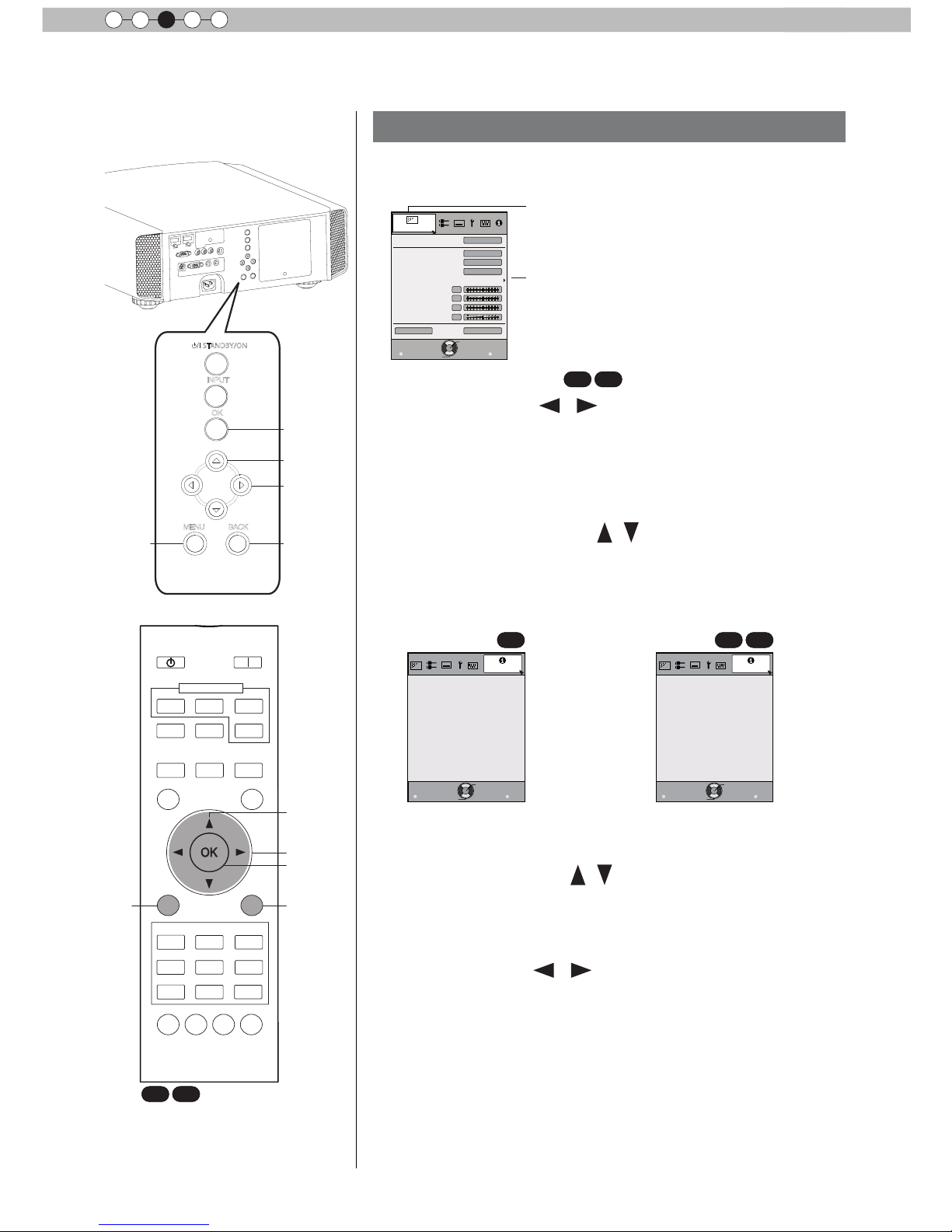
2 Press cursor ( / ) to select a submenu.
● A submenu (picture adjust, input signal, installation, display
setup, function, information) is selected:
● If one selects "Information", information about the currently
selected video input and PC input are displayed at the bottom
of the menu.
3 Press OK or cursor ( / ).
● Sub-menu item is displayed.
● Sub-menu items vary depending on the input signal and the
picture mode. See "Content menu" on the next page for more
details.
4 Press the cursor ( / ) to select the items to
adjust.
If the name of a submenu item is displayed in a dimmed manner,
it cannot be selected.
5 Press cursor ( / ) to change settings.
6 After adjusting, press BACK.
Every time it is pressed, you will return to the respective previous
menu screen.
7 Repeat steps 6-2 to adjust other items.
After all adjustments are done, press MENU, and the menu
disappears from the screen.
STANDBY/ON
MENU
BACK
INPUT
OK
BACK
HIDE
LIGHT
LENS AP.
C.M.D
PC
HDMI 1
STAND BY
ASPECT
HDMI 2
ANAMO
COMP.
LENS.
CONTROL
MENU
GAMMA
P.FILE
COLOR
ADJ.
PIC.
ON
FILM
NATURAL
STAGE 3D
USER1
USER2
THX
ANIME
CINEMA
PICTURE MODE
INPUT
TEMP
COLOR
1
1
2,5
2,5
3,4
3,4
3
3
6
6
X7 X9
Exit
MENU
BACK
Back
Select
Operate
160H
HDMI-2
1080p60
10bit
Input
Source
Deep Color
Lamp Time
Information
:
:
:
:
Exit
MENU
BACK
Back
Select
Operate
160H
HDMI-2
1080p60
10bit
Input
Source
Deep Color
Lamp Time
Information
:
:
:
:
X7 X9
Example: When inputting
PC signals
Example: Input of signals
other than PC signals
COM
Page 32

Operation
45
ENGLISH
Adjustments and settings in the menu (continued)
Menu item description
All numbers for the items within [ ]are default settings.
● It is possible to operate all items displayed in the menu display by pressing OK/BACK or the cursor (up,
down, left, right arrows).
● Displayed items vary depending on the selected item in the menu and type of input signal or absence of
any signal.
[1] Picture Adjust
Picture Mode
Please refer to the description of each mode, and then use the mode to best suited for
you. Moreover, it is possible to adjust the image quality by using a user 1, 2, and 3.
Settings: Film, Cinema, Animation, Natural, Stage, 3D, THX, User 1, User 2, User 3.
[Natural]
Film This quality setting is similar to the texture of the lm setting. It is suitable for watching
movies in general.
This image setting is based on the DCI standard and brings to life brightly colored
pictures. Suitable for viewing action movies and brightly colored images.
DCI: Shorthand for Digital Cinema Initiatives.
Animation
An image quality setting for watching animation movies and the like.
Natural
It is an image quality setting with natural color/tone. Suitable for viewing video material,
such as dramas/serials.
Stage
This image quality setting is suitable for watching of live events, e.g. on a stage.
3D
This is an image quality setting for watching 3D movies.
User 1
User 2
User 3
X3
The users 1, 2, and 3 should adjust the image quality as desired in each case. Data of the
last adjustment is saved.
THX
X7 X9
It is an image setting certied by the company THX.
Color Prole
X7 X9
It selects a color prole to suit the input source. Depending on the settings, the items that
can be set in the "Picture Mode" vary. (See Table 1)
The color prole is selected based on the video production. We recommend to match the
color prole of the video you want to watch.
(*) If you select "Off", it is impossible to perform any picture adjust for other color temp.
other than "Lamp power" and "Lens aperture" under "Advance", and also not gamma or
sharpness.
Setting: Film 1, Film 2, Cinema 1, Cinema 2, Standard, Anime 1, Anime 2, Video, Vivid,
Adobe, Stage, 3D, Off.
Depending on the picture mode, the default values will change. [See table 1]
Film 1 This is a prole that comes close to a color space that resembles using a Xenon lamp to
transmit a lm used for movies by the Eastman Kodak Company.
Film 2 This is a prole that comes close to a color space that resembles using a Xenon lamp to
transmit a lm used for movies by the FUJIFILM Corporation.
Cinema 1
This is a prole that resembles the color space of the DCI standard.
Cinema 2
This is a prole that resembles the color space of HDTV.
Standard
It is a prole with an especially rich representation of the lm-specic colors.
HDTV: Shorthand for High Denition Television.
Anime 1
This is a prole suitable for CG-animations, which can be often found in Hollywood-
produced animated series.
It is intended for animations with multiple bright colors.
Anime 2
This is a prole suitable for animation cel-style animation series, which are common in
Japan.
It is intended for animations with many dim colors.
Video
This prole is suitable e.g. for TV / drama / sports.
Vivid
This is a prole with rich sense of color, which makes it suitable for games.
Adobe
This is the color prole for Adobe RGB.
(*) Adobe, and the Adobe logo are registered trademarks or trademarks of Adobe
Systems Incorporated in the United States and/or other countries.
Stage
This prole is suitable for live music, orchestra and opera concerts, theater, etc.
3D
This is the most suitable prole when using 3D-glasses.
Off
It is a mode that does not adjust the color management.
Cinema
Page 33

46
Operation
3
Adjustments and settings in the menu (continued)
Picture Mode
Film Cinema Anime Natural Stage 3D THX User 1, 2
Color Prole
Film 1 Cinema 1 Anime 1 Video Stage 3D THX
Everything
is displayed
except for
Film 1 and
Film2.
Film 2 Cinema 2 Anime 2 Vivid Standard Standard
Standard Standard Adobe Vivid
Standard
This is the default value according to the picture mode.
[Table 1] The setting contents and default values
X7 X9
of the color proles for the picture mode
Color Temp.
It is possible to set the color temp.
To "[1-1] Color Temp." of the submenu
Gamma
It is possible to set the gamma curve. Please set to your preference.
Settings: Normal, A (3D), B (3D), Film 1, Film 2, Film 3 Film 4, A, B, C, D, Custom 1,
Custom 2, Custom 3 [Normal]
Normal
Typically we recommend this setting.
A (3D)
B (3D)
A (3D), B (3D) can only be set, if the "Picture Mode" is "3D".
This is the normal gamma curve for 3D.
A (3D) will be brighter.
Film 1, 2, 3, 4 can only be set if the "Picture Mode" is set to "Film"
X7 X9
Film 1 This is a gamma curve that approximates the characteristics of an Eastman Kodak
Company lm for movies.
Film 2 This is a gamma curve that approximate the gamma curve characteristics of a
cinematographic lm made by the FUJIFILM Corporation.
Film 3 This is a gamma curve that is even more focused on tone for the gamma of Film 1.
Film 4 This is a gamma curve that emphasizes more contrast for the gamma of Film 2.
A, B, C, D cannot be set if the "Picture Mode" is "3D".
A
B
C
D
In regard to normal gamma, this is a gamma curve focused on tone.
This is a gamma curve for the lm's unique S curve.
This is a gamma curve that – in regard to the gamma of B – emphasized even more the
feeling of contrast.
For normal, this is a gamma curve where the intermediate gradations look very bright.
Custom 1
Custom 2
Custom 3
Custom 1, 2, 3 cannot be set if the "Picture Mode" is "3D".
Under submenu "[1-2-2] Custom Gamma", it is possible to change the gamma curve and
save it.
The initial value of Custom 1, 2, and 3 is the same as for "Normal".
Film Tone
X7 X9
You can reproduce the intensity of the exposure image.
(*) This function can be set if the "Picture Mode" is set to "Film".
White
Red
Settings: (The more under-exposure, the darker) -16 to 16 (the more over-exposure, the
brighter) [0]
Setting: (under-exposure to for red), -16 to 16 (over-exposure for red) [0]
Green
Settings: (under-exposure for green) -16 to 16 (over-exposure for green) [0]
Blue
Settings: (under-exposure for blue) -16 to 16 (over-exposure for blue) [0]
Dark/Bright Level
X7 X9
Compensating darkness / brightness of an area.
(*) It is possible to set it unless the "Picture Mode" is set to "Film".
Dark Level
Values: (makes dark areas darker) -7 to 7 (brightens dark areas) [0]
Bright Level
Settings: (darkens bright areas) -7 to 7 (makes bright areas brighter) [0]
Page 34

Operation
47
ENGLISH
Adjustments and settings in the menu (continued)
Contrast
Adjusts the contrast of the video images.
Settings: (blackish) -50 50 (whitish)
Brightness
You can adjust the brightness of the video image.
Settings: (dark) -50 to 50 (bright)
Color
Adjust the color intensity of the video images.
Settings: (dim), -50 to 50 (saturated)
Tint
Adjusts the image tint of the video images.
Settings: (reddish) -50 to 50 (greenish)
Advanced
Functions such as contour correction, custom gamma and color management can be set
to sub-menu "[1-2] Advanced".
Reset
Sets settings to default factory settings.
[1-1] Color Temp.
Set the color temp. of the video images.
Please adjust to your preference.
(*) For this setting, the setting items can differ in accordance with the "Picture Mode".
Adjustment is not possible when set to “THX".
Settings: (Preset value), Xenon1, Xenon2, Xenon3, Custom 1, Custom 2,
Custom 3 [Preset value]
(Preset value)
The color temp. can be adjusted within the range of 5500K to 9500K in steps of 500K.
It is said that a value of 6500K produces a well balanced video image.
Settings: Between (reddish) 5500-9500 (bluish) in steps of 500K [6500]
Xenon1
Xenon2
Xenon3
This reproduces the color temp. characteristics of a xenon lamp being used in cinemas.
A light source color that is emitted by a lm projector.
A light source color emitted by a projector used for digital cinema.
A light source color that looks cooler than that of the Xenon2.
Offset
Xenon 1, Xenon 2, Xenon 3 can each be adjusted based on the dark color of the video
images.
Red
Settings: (Weak red) -50 to 50 (strong red) [0]
Green
Setting: (Weak green), -50 to 50 (strong green) [0]
Blue
Setting: (Weak blue) -50 to 50 (strong blue) [0]
Custom 1
Custom 2
Custom 3
You can adjust the color temp. and save each Custom 1, 2, and 3.Please save your
preferred adjustment values and enjoy it.
Gain
It is possible to adjust the bright part of the video images for each color.
Red
Settings: (Weak red) -50 to 50 (strong red) [0]
Green
Setting: (Weak green) -255 to 0 (strong green) [0]
Blue
Setting: (Weak blue) -255 to 0 (strong blue) [0]
Offset
For each color, the dark areas of the video images can be adjusted.
Red
Green
Blue
Settings: (Weak red) -50 to 50 (strong red) [0]
Setting: (Weak green) -50 to 50 (strong green) [0]
Setting: (Weak blue) -50 to 50 (strong blue) [0]
Page 35

48
Operation
3
Adjustments and settings in the menu (continued)
[1-2] Advanced
Sharpness
You can set the sharpness and detail enhance to "[1-2-1] Sharpness" of the submenu
NR
Reduces the noise of the video images. Please adjust to your preference.
RNR
Adjusts the intensity of random noise elimination of the image.
Values: (Low) 0 to16 (strong) [0]
MNR
Adjusts the intensity of mosquito noise elimination of the video images.
(*) It is not possible to set it when the "Picture Mode" is set to "3D".
Moreover, it is not possible to set it when there is an input of HD input signals.
Values: (Low) 0 to16 (strong) [0]
BNR
Reduces the block noise of the video images.
(*) ) It is not possible to set it when the "Picture Mode" is set to "3D"
Moreover, it is not possible to set it when there is an input of HD input signals.
Settings: On, Off [Off]
Color Space
X3
You can switch the color space display of the projector output.
Settings: Standard, Wide 1, Wide 2
Standard
Wide 1
Wide 2
Equivalent to the HDTV color space
Equivalent to the color space of the DCI standard
A color space that is broader than Wide1
Custom Gamma
It is possible to set the gamma curve and save it. Please adjust to your preference.
To "[1-2-2] Custom Gamma" of the submenu
Color Management
X7 X9
It is possible to set the color of the screen to the preferred color and save it.
To "[1-2-3] Color Management" of the submenu.
Clear Motion Drive
It improves video images with fast movements to produce clear video images with little
residual image retention.
For PC and 3D signals, the "Clear motion Drive” cannot be set.
Moreover, the images in some scenes may be distorted. In such a case, please select
"Off".
Settings: Off, Mode 1, Mode 2, Mode 3, Mode 4, Film motion [Off]
Off
Off
Mode 1
Black insertion weak
Mode 2
Black interpolation strong
Mode 3
Interpolation weak
Mode 4
Interpolation strong
Film motion
With 60i/60p signals, e.g of TV-broadcast and DVDs, original 24 frame video image
footage is changed to a 24 frame display.
(*) 24p will not function.
CMD Demo
It is possible to conrm the effect of the setting of Mode 3 and Mode 4 of the Clear motion
drive. Upon pressing the button "OK", it will be displayed on all sides of a screen in the
center split into two parts. Finally, it will turn to "Off”. It cannot be set for PC and 3D
signals.
Settings: Left -> right -> top -> down -> Off (changed with "OK" button) [Off]
Left The left screen displays a demonstration of the Clear motion drive.
Right The right screen displays a demonstration of the Clear motion drive.
Top The upper screen displays a demo of the Clear motion drive.
Down The screen below displays a demo of the Clear motion drive.
Off The Demo of the Clear motion drive is turned off.
Lens Aperture
Adjusts the amount with which the optical iris is squeezed. A setting of 0 means fully
opened.
Settings: (Dark) -15 to 0 (bright) [0]
Page 36

Operation
49
ENGLISH
Adjustments and settings in the menu (continued)
Custom Gamma
Correction Value
White
Red
Green
Blue
Reset
1023
512
50
100(%)
Custom1
Custom2
Custom3
0
Picture Adjust
Exit
MENU
BACK
Back
Select
Operate
Normal
>
>
Gradation at the
selected point.
Gamma curve
Gradation diagram corresponding
to the gamma curve.
(*)
Lamp Power
It is possible to change the brightness of the lamp.
(*) If continually used with "High", the lamp will become dark earlier.
(*) The more one lets the interior temperature of the device rise due to generation of heat,
the less the level of tolerance against high temperatures.
(*) For about 60 seconds after the lamp is lit, the lamp cannot be switched off.
Settings: Normal, High [Normal]
Normal Normally this setting is chosen.(160W drive)
High In a bright room, when the video is hard to see, this setting is chosen.(220W drive)
[1-2-1] Sharpness
Sharpness
Emphasizes the outlines of video images. Please adjust to your preference.
Values: 0 to 50 (clear)
Detail Enhancement
It makes minute details of the video images stand out. Please adjust to your preference.
Values: 0 to 50 (strong)
[1-2-2] Custom Gamma
Custom 1~3
[1] It is possible to select a gamma curve adjustment for Custom 1, 2, and 3 under the
"Gamma" of the picture adjust and then save it.
Please adjust to your preference.
(*) Initial values of Custom 1, 2, and 3 are the same as for "Normal".
(*) Please refer to the gure at the bottom of the menu in two frames for adjustment.
(*) It is recommended that you read "Gamma Curve" (page reference: 56) for hints about
adjustment.
Correction Value
You can choose to add the underlying gamma curve adjustment.
(*) Can choose any setting, as the default gamma curve will always appear linear.
Settings: Normal, A, B, C, D
(brightens in particular dark to intermediate parts) 1.8 to 2.6 (darkens in particular dark to
intermediate parts) in the range of values with increments of 0.1 [Normal]
Gamma Adjustment
The gamma curve for "green" is being displayed as being representative. If "white", "red,"
"green" or "blue" are selected, the corresponding color curves are displayed.
Place the cursor on a gamma curve with 12 points with the buttons for left and right, and
then use the buttons for up and down buttons to move those points up or down.
White
Red, green and blue can be adjusted at the same time.
Red
It is possible to adjust the gamma curve of red.
Green
It is possible to adjust the gamma curve for green.
Blue
It is possible to adjust the gamma curve for blue.
Reset
The same data as for the "Normal" mode are used.
(*) When you exit the adjustment menu of Custom Gamma, please save the adjustment
values.
You can return to the original data, which should be saved.
Page 37

50
Operation
3
Adjustments and settings in the menu (continued)
[1-2-3] Color Management
X7 X9
Custom 1~3
Set the 7 color axis (red / orange / yellow / green / cyan / blue / magenta) color as you
like and save it then. For example you may want to change only the red color of roses.
Please adjust to your preference. According to your adjustments, the input image in the
background changes. It is possible to conrm the video image before adjustment by
pressing the "HIDE" button of the remote control.
Pause
It is possible to display the input video image of the background being adjusted as a still
picture.
Settings: On, Off [Off]
On
Off
Freezes the input video image.
Unfreezes the input video image.
Color
It is possible with the 7 colors of red, orange, yellow, green, cyan, blue and magenta to
precisely adjust the hue, color saturation and brightness, and then save it. Please adjust
to your preference.
Axis position
Fine-tune the position of the central axis of the selected color further.
Settings: -30 to 30 [0]
Hue
Adjust the hue.
Settings: -30 to 30 [0]
Saturation Adjust the color saturation.
Settings: (dim color), -30 to 30 (vivid colors) [0]
Brightnes Adjust the brightness.
Settings: (dark) -30 to 30 (bright colors) [0]
[2] Input Signal
HDMI It is possible to set this if one selects the HDMI terminal to the submenu "[2-1] HDMI".
COMP. This can be set if one selects the COMP. terminal to the submenu "[2-2] COMP."
PC
X7 X9
This can be set if one selects the PC terminal to the submenu "[2-3] PC".
Picture Position
Please adjust if the edges of the picture are partially missing due to the timing of
horizontal and vertical synchronization signals. The value of the picture position depends
on the input signal.
(*) Depending on the input signal, it may be the case that not everything of the video
image is displayed.
(*) When there is a 3D input signal, adjustment is not possible.
Horizontal position
Vertical position
This aligns the horizontal direction of the image position.
This aligns the vertical positions of the image.
Aspect (Video)
(*) It is displayed when there is a video signal input.
(*) If set to3D, ratio is xed to 16:9.
Settings: 4:3, 16:9, Zoom [16:9]
4:3
Sets the screen size of the image to 4:3. For HD signals, left and right sides are reduced.
16:9
Sets the screen size of the video image screen to 16:9. For SD signals left and right sides
are expanded.
Zoom
Zooms the video images. (*) For HD signals, this cannot be selected.
Aspect (PC)
Sets the video image screen size when there is a PC video signal input.
(*) Is displayed when there is a PC signal input.
Settings: Auto, 1:1, Full [Auto]
Auto Positions the video image screen in the center of the display range, to ll the screen.
Depending on the size of the video screen, left and right black borders will be drawn.
1:1
The video image screen size is displayed with the size of the input image.
Depending on the input video image, the screen will become smaller or part of the input
image off the screen is cut off.
Full It does not keep the aspect ratio of the video image screen and lls the entire screen.
Page 38

Operation
51
ENGLISH
Adjustments and settings in the menu (continued)
Mask
It hides the upper, lower, left and right borders of the screen with a black mask. Can be
individually adjusted vertically and horizontally. Please adjust to your preference.
Setting: Off, 2.5%, 5%, Custom [Off]
Off Not masked.
2.5%
Compared to the original video images, around 2.5% around the video images are
masked.
5%
Compared to the original video images, around 5% around the video images are masked.
Custom
Left
Compared to the original video images, around 5% of the video images are masked on
the left side.
Settings: 0 ~ 5% [0]
Right
Compared to the original video images, around 5% of the video images is masked on the
right side.
Settings: 0 ~ 5% [0]
Upper
Compared to the original video images, around 5% of the video images are masked at the
upper side.
Settings: 0 ~ 5% [0]
Down
Compared to the original video images, around 5% of the video images are masked at the
bottom side.
Settings: 0 ~ 5% [0]
Progressive
Interlaced signals (480i/576i/1080i) are converted to progressive signals. Interpolates
interlaced signal video images with video images from the surrounding. Please set to your
preference.
Settings: Auto, Off [Auto]
Auto It is automatically detected if the 24p video images, which can be seen in the lm screens,
interlaced signals from the original video material or if they are the product of signal
conversion and are interpolated accordingly.
Off The interpolation of video images as interlaced video signals, e.g. video material is done.
[2-1] HDMI
Input
(*) It can be set when the HDMI terminal is selected.
Sets the dynamic range of the input video images (scale). Dark and bright areas, which
are not matched to the range, might get brighter or darker. If you are unsure of the input
signal dynamic range, please check under "Level Check".
Settings: Standard, Enhance, Super White [Standard]
Standard It gets set if the dynamic image range of the gradation level of the input image is set to
16-235. In case of a video signal, please set it up here.
Enhanced
It is set if the dynamic range of the input video scale level is 0-255.If these are PC signals,
please set them here.
Super White
It is set if the dynamic range of the input video scale level is 16-255.Please set the output
to video equipment compatible with Super White for Super White-enabled DVD / BD etc.
Check the input level
0 235
255 16
You can conrm the dynamic range of the input signal.A pattern as shown in the
illustration is displayed in the four corners and center of the screen. Please compare the
dynamic range of input signal with this pattern illustration and conrm.
(*) The number in the illustration is the scale level. This number is not displayed. The
illustration of the gradation in the gure is accentuated for explanatory purposes It is
different from the actual scale level.
Color Space
It sets the color space of the input signal.
Settings: Auto, YCbCr(4:4:4), YCbCr(4:2:2), RGB [Auto]
Auto YCbCr(4:4:4), YCbCr(4:2:2), RGB signals are automatically detected and congured.
YCbCr (4:4:4)
Sets it if the input of the YCbCr(4:4:4) input video image signal is performed.
YCbCr (4:2:2)
Sets it if the input of the YCbCr(4:2:2) input video image signal is performed.
RGB
It is set when the RGB video signals input is performed.
Control with HDMI
Congured communication of the HDMI equipment control
Settings: On, Off [Off]
Page 39

52
Operation
3
Adjustments and settings in the menu (continued)
3D Format
Sets the format of the 3D input signal.
(*) It is recommended to read "On 3D" (reference page: 53) before watching 3D video
images.
Settings: Auto, Frame Packing, Side by Side, Top & Bottom, 2D [Auto]
Auto Is set automatically.
Frame Packing
Select this if the 3D input signal is the frame pack method.
Side by Side
Select this if the 3D input signal is the side by side method.
Top & Bottom
Select this if the 3D input signal is the top and down method.
2D
Projected as a 2D signal.
[2-2] COMP.
X7 X9
(*) It can be set when the COMP. terminal is selected.
Color Space
It congures the input signal method of the component input terminal.
Settings: Y Pb/Cb Pr/Cr, RGB [Y Pb/Cb Pr/Cr]
Y Pb/Cb Pr/Cr
It is set for the component video image input signal.
RGB
It is set for the RGB video image input signal.
[2-3] PC
(*) Setting can be done when selecting a PC terminal.
Auto Alignment
The picture position of Tracking and Phase are automatically adjusted.
Tracking
Adjusts the size and display of the horizontal direction and display area of the video
images.
(Depending on the signal, there is normally no need to be adjusted.)
Phase
Adjusts the ickering and blur of the video images.
(Depending on the signal, there is normally no need to adjustment.)
Picture Position
Adjust the display of the picture position.
Horizontal Adjusts the horiz. of the video image.
Vertical Adjusts the vertical position of the image.
[3] Installation
Lens Control To Sub-menu "[3-1] Lens Control"
Pixel Adjust To submenu "[3-2] Pixel Adjust"
Installation Style
Matching the state of the projector’s projection, one can switch horizontal and vertical ip
/ forward switch.
Settings: Front, Ceiling Mount (Front), Rear, Ceiling Mount (RE) [Front]
Front
Front upright projection mode.
Ceiling Mount (F)
Ceiling/front projection mode.
Rear
Rear upright projection mode.
Ceiling Mount (R)
Ceiling/ rear projection mode.
Keystone
In regards to the projection plane, any occurring keystone distortion is adjusted in case
the installation location is inclined.
(*) There may be
instances, when the video image - after having corrected keystone
distortion - will not match the screen. The position with a shift correction of 0% position is
an exception.
(*) When there is a 3D input signal, adjustment is not possible.
Horizontal Adjusts the horizontal keystone.
Settings: -40 to 40 [0]
Vertical Adjusts the vertical keystone.
Settings: -30 to 30 [0]
Page 40

Operation
53
ENGLISH
Adjustments and settings in the menu (continued)
Anamorphic
The video images are projected after being enlarged in the vertical direction of the panel
resolution. This setting is used when one uses the anamorphic lens to enlarge them in the
horizontal direction.
(*) Anamorphic mode cannot be set when there is a 3D signal input.
If a 3D signal is fed in when Anamorphic mode is set to A or B, Anamorphic mode is
automatically turned Off.
Settings: A, B, Off [Off]
A
Video with an aspect ratio of 2.35:1 is enlarged in the vertical direction of the panel
resolution and then projected.
B
Video with an aspect ratio of 16:9 are displayed by reducing them in the horizontal
direction, without changing their size in the vertical direction.
Off
Used when watching video images other than those with a 2.35:1 aspect ratio while using
an anamorphic lens. 2.35:1 video images are projected without any changes. (Black
bands appear on all sides)
Screen Adjust
It corrects the white balance fault according to the reective properties of the projection
screen. Please adjust to your preference.
Black Level
Sets the black level when used indoors.
Settings: 0 to 10 [0]
[3-1] Lens Control
It controls each motorized functions of the lens during the projector-installation.
Focus
This function is used to adjust the focus.
Zoom
This function is used to adjust the zoom.
Shift
This function is used to adjust the shift.
Lens Cover
This function is used to set if the lens cover should be linked with a power supply for
opening/closing, or if it should be left open.
Settings: Auto, Open [Auto]
Auto This opens/closes the lens cover when it is linked to on/off of a power supply.
Open Regardless if the power supply is on on/off, the lens cover is always open.
Image pattern
It is possible to adjust the projection screen during adjustment of the focus zoom shift.
Settings: On, Off [On]
On During the adjustment, the image pattern is displayed.
The image pattern is displayed in conjunction with the above setting items.
Off The external input signal is displayed without displaying the image pattern.
Lock
This sets the lens control to on/off.
Settings: On, Off [Off]
On It is not possible to adjust the above setting items. If the remote control button "LENS"
button is pressed, a warning message is issued.
Off This functions as lens control function.
[3-2] Pixel Adjust
This ne tunes each slight color errors in the horizontal/vertical directions of the video
images in units of 1 pixel.
(*) It is impossible to match all image pixels on the screen. Due to the equipment, there
will always be some gaps.
(*) In case the image is reversed, or upside-down, the horizontal and vertical directions
are reversed.
(*) Please perform adjustments on a clear still picture.
(*) For ne tuning, the effects of adjustments may be difcult to understand for some
video images.
Page 41

54
Operation
3
Horiz. Red
Horiz. Green
Horiz. Blue
(Move red to the left) 1 to 5 (move red to the right) [3]
(Move green to the left), 1 to 5 (move red to the right) [3]
(Move blue to the left) 1 to 5 (move red to the right) [3]
Horiz Red
Horiz Green
Horiz Blue
(move red down) 1 to 5 (move red up) [3]
(Move green down) 1 to 5 (move green up) [3]
(move blue down) 1 to 5 (move blue up) [3]
[4] Display Setup
Back Color
Sets the color of the background, which is displayed without an input signal.
Settings: Blue, Black [Blue]
Blue
Sets the background color to blue.
Black
Sets the background color to black.
Menu Position
Sets the picture position of the menu. Please set to your preferred position Navigate the
menu by pressing the left or right keys when you have selected an item. Moreover, if
one presses the button [OK], an image illustration appears at the position of the menu.
The highlighted position in the illustration moves by use of the left and right keys. If one
presses [OK], the menu moves to the highlighted position.
If you press the key to the right, the menu will move starting from the top left -> top right
-> central -> bottom right -> bottom left and then back to the upper left.
By pressing of the left key, the menu moves in the opposite direction. [Upper left]
Menu Display
Sets the time for the menu to be displayed.
Settings: 15 seconds, On [On]
15 sec
If there is no menu operation for 15 seconds, the menu display vanishes.
On
Display always.
Line Display
Congures if input is displayed or not when input is switched.
value: 5 seconds, on [5 seconds]
5 sec
Displays for 5 seconds.
On
Not displayed.
Source Display
Congures whether or not to display the signal, when the input is switched.
Settings: On, Off [On]
On
Display.
Off
Not displayed.
Logo
Congures whether or not to display the "D-ILA" logo upon activation.
Settings: On, Off [On]
On
Displayed for 5 seconds.
Off
Not displayed.
[5] Function
Trigger
Congures 12V output to an external screen equipped with a trigger function.
Settings: Off, On(Power), On(Anamo) [Off]
Off
No output.
On (Power) When turned on, control signals (12V) from the trigger terminal are emitted.
If you turn off the power, the output of the control signal stops.
During standby mode, an output will occur if the OPERATE button is pressed.
After cooling, the output stops when you go back to standby.
On (Anamo) Control signals (12V) are emitted when the Anamorphic mode is set from "Off” to “A” or
“B”. If the Anamorphic mode is set to "A" or "B", the operation in this state equals "On
(Power)".
Off Timer
Sets Off Timer function and its time.
* If there are no operations, the unit powers off automatically.
* It powers off automatically even while projecting an image.
Settings: Off, 1 hour, 2 hours, 3 hours, 4 hours [Off]
Adjustments and settings in the menu (continued)
Page 42
Operation
55
ENGLISH
Adjustments and settings in the menu (continued)
Off
Power is not turned off.
1 hour
Power is turned off automatically after 1 hour.
2 hours
Power is turned off automatically after 2 hours.
3 hours
Power is turned off automatically after 3 hours.
4 hours
Power is turned off automatically after 4 hours.
High Altitude Mode
Set to use at low pressure locations (900m above sea level).
Settings: On, Off [Off]
On
Set.
Off
Do not set.
Communication
terminal
X7 X9
Sets the used control terminal. It is not possible to use it at the same time.
Settings: RS-232C, LAN [RS-232C]
RS-232C Sets the RS-232C terminal.
LAN Sets the LAN terminal.
Network
X7 X9
It is displayed, if the setting of the "Communication terminal” to the submenu "[5-1]
Network" is set to "LAN".
Lamp reset Reset of the lamp use time to "0".
[5-1] Network
X7 X9
DHCP client
Sets the DHCP client.
Settings: On, Off [Off]
On
Obtains automatically an IP address from within the connected network's DHCP server.
* The automatic retrieval starts with the "Set" within the menu.
Off
The network settings are being done manually.
IP address
Sets the IP address. [192.168.0.2]
Subnet mask
Sets the subnet mask. [255.255.255.0]
Default gateway
Sets the default gateway. [192.168.0.254]
MAC address
Displays the MAC address of the unit.
Set
[5-1] Reects the network setting.
[6] Information
Displays upon HDMI/COMP. input
Input
Displays video image input terminal.
Source
Displays the name of the input source.
Deep Color
Displays the color bit depth concerning an input video image signal.
* When you input YCbCr (4:2:2), it is not displayed.
* When there is information about DeepColor from the source device, it is displayed.
Lamp Time
Displays the lamp use time.
Displays upon PC input
Input
Displays video image input terminal.
Resolution
Displays image resolution.
H Frequency
Displays the H Frequency.
V Frequency
Displays V Frequency.
Deep Color
Displays the color bit depth concerning an input video image signal.
* When you input YCbCr (4:2:2), it is not displayed.
* When there is information about DeepColor from the source device, it is displayed.
Lamp Time
Displays the lamp use time.
Page 43

56
Operation
3
Gamma Curve
The description of the gamma curve that assumes a gamma curve unit. Please read the relevant detailed description
and professional books.
The gamma curve of the projector to the input video signal determines for each color the relative value of its light output.
The value of the input video image signal is displayed as a percentage - with
both being displayed in % as units - of the maximum light input signal for brightness and the brightness output value as a percentage of the maximum output
value of each color or the projector. In relation to the signal value of 50% of the
input, it projects with brightness output value of 50%. However, a light output
value of 0% is not completely black and neither no projection. As the possibility of the projector to reproduce blackness is limited, it will be actually slightly
brighter.
The input video image signal value becomes a continuous curve of 0% to 100%
for the gamma curve, which can be set with the projector. Moreover, it is impossible to get only one light output value for the input video image signal value.
The gamma curve can be set for each color, i.e. red, green and blue. By selecting the white color, the 3 colors can be adjusted at the same time.
A larger angle of inclination of the gamma curve leads to a greater gap of the
light output value of that area and makes it easier to distinguish the video images. A low angle of inclination leads, on the
contrary, to the difference in that area becoming smaller, so that the video images are harder to distinguish. If it is impossible to get an inclination angle, so that it is chosen to become horizontal, the gap in that area vanished and it might
be impossible to distinguish the video images.
The light output
A
B C
Input sig-
nal value
100%
100%
0%
0%
A
B
C
Suppose you knew the inclination of the input video image signal values of the watched video images, and would
increase the slope of the portion of this area and attenuate the slope of other areas. It would then be easier to determine
the video images. Also, if you did not know the inclination of the input video image signal value of the watched video
images, adjustment would be difcult.However, there are some trends of the distribution of the input video image signal
value depending on the type of video content. As some typical examples are prepared in the [Gamma] (Reference Page:
46), it is recommended to perform similar settings before watching.
Some methods about how to adjust the gamma curve are presented here, but in reality one can think of various adjust-
ment methods, for examp
le where red, green and blue are individually adjusted. In your own image creation, please
enjoy the process of trial and error.
The light output
The light output
100%
100%
0%
0%
Input sig-
nal value
The distribution of the input signal
100%
100%
0%
0%
Input sig-
nal value
The distribution of the input signal
Operation guide (glossary)
The light output
50%
50%
Input signal
value
0%
100%
100%
0%
Page 44

Operation
57
ENGLISH
This is a description for the 3D-method using this unit, 3D-glasses (sold separately: PK-AG1-B) and an 3D
synchro emitter (sold separately: PK-EM1). Set the 3D TV and 3D compatibility software to an appropriate
viewing standard. For viewing, a separate unit compatible with
3D playback is needed. For detailed description of other 3D
methods, please read specialized books on this topic. (For the
sake of explanation, a simplied and exaggerated picture is
used.)
The 3D scheme of this unit utilizes the principle of binocular
parallax. It projects with the frame sequential method, where
separately alternating images are produced for the left and
right eye. Opening and closing of 3D glasses tted with liquid
crystal shutters are controlled in such a way, that video images
corresponding to the ri
ght/left eye and are only visible for the
respective eye. As a result, one can watch three-dimensional
images.
Due to the difference of the video images both eyes see, the
brain perceives them in a stereoscopic way. The video images
that can be seen by the respective eyes are articially produced. Due to the exposure of the eyes to the respective video
images, the brain is induced to create a ster
eoscopic image,
which is not present as a real object. In other words, it is a use
of virtual images.
立体映像
Eye
Video images
seen with the
right eye
Video images
seen with the left
eye
Stereoscopic
video image
Binocular parallax:
Difference of the view
on a single object
when seen from the
left and right eyes,
respectively.
CAUTION
• Please stop watching at once if
you do not feel well and consult a
physician if necessary.
• People who already have a kind of
photosensitivity, sufferers from heart
disease, and people in poor physical
condition should not watch 3D video
images of this device, which makes
use of 3D glasses.
• It is recommended that you take
a break periodically. Length and
frequency of the required break
differ due to individual differences.
Please judge for yourself.
CAUTION
• The comprehensive brain function
to judge stereoscopic vision and
which include a feeling for real
distances, develops while growing
up by touching and seeing real
objects, but in early childhood, it
is still in an underdeveloped state.
Even though there are individual
differences, children under 5 are
still developing. Letting them
frequently watch virtual 3D video
images can be an obstacle for the
development of a comprehensive
three-dimensional feel.
• For younger children may suddenly
become sick, because they continue
watching without realizing symptoms
like 3D sickness or deterioration
of health until after watching 3D
images. Please accompany your
while it watches. And please be
careful when it comes to your child’s
bodily condition and state.
Description of the 3D method
Original
Page 45

58
Operation
3
Separate images which can be seen by the right eye and left eye, respectively, are taken and produced
separately. Therefore, the image for the left eye is only visible to the left eye, and the images for the right
eye only or the right eye. The Human brain perceives stereoscopic images based on image information on
both sides.
The closer one looks at stereoscopic images, the greater the binocular d
isparity, which means greater
perception of outward projection. At the same time, the focus has to t the screen, but the projecting image
and the focus cause a great contradiction. This causes visual fatigue and discomfort.
Left-eye image Right-eye image
Stereoscopic
video image
CAUTION
In most cases, 3D images taken
or produced are horizontally
arranged respectively. If these
images were not horizontally
arranged for left and right eye
movement when watching,
the brain could not perceive a
stereoscopic image, but would
still recognize a double image. As
such video images can cause 3D
sickness, please do not hold the
3D glasses slanted relative to the
video images.
CAUTION
Please watch from a distance three times the height of the screen. For example, for a
projection size of 120, it should be approximately 4.5m, and for an 80-type, it should
be around of 3 m. Please refer to page 19, where one can nd a table with the screen
seizes and at the same height. Choosing a distance closer than recommended may
cause eyestrain.
Page 46
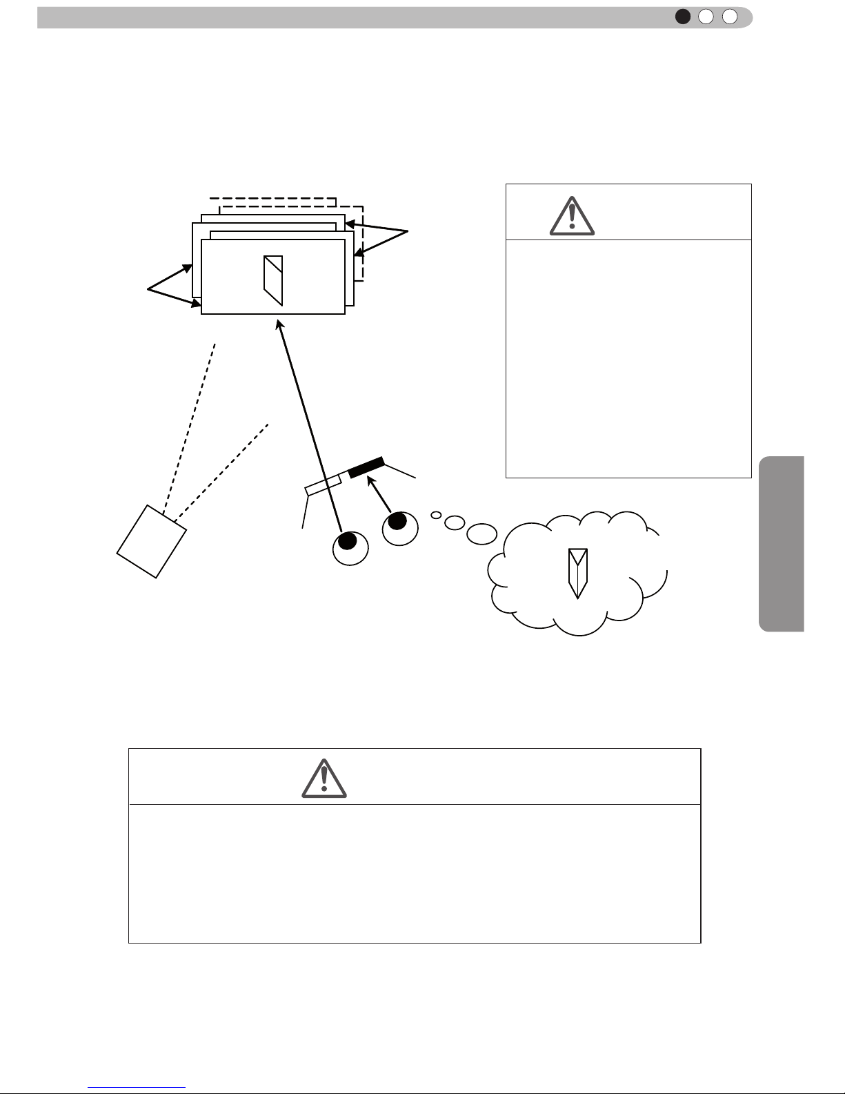
Operation
59
ENGLISH
The frame sequential method is a way of displaying video images left and right sequentially. The projector
projects the video images used for the left- and right eyes onto the screen. The video images for the left
and right side are only visible with the respective eye, as the left and right side of the 3D glasses are
opened and shut by a liquid crystal shutter. As a result, the left and right images are seen by the eye and
show a 3D image.
In order to match the timing of the display of video images and the timing of the opening/closing of the 3D
glasses liquid crystal shutters and it is necessary to show to the eyes only those video images, for the left
or right eye, respectively, the projector of this unit sends these timing data from the 3D synchro emitter to
the 3D glasses with infrare
d rays.
Left-
eye
image
Right-eye
image
Eye
Close
Open
Video image projection
with the projector frame
sequential method
3D-glasses
CAUTION
• As the video images for the left
and right side ash alternatively
when displayed, we urge you to
refrain from looking at the screen
with naked eyes. When viewed
with several people, please
prepare glasses for them.
• These 3D glasses are only for the
3D video images of this device.
Please do not use it for watching
other objects or 2D video images.
CAUTION
• In regard to the 3D emitter, please direct the 3D glasses in such a way towards it, that
the infrared rays can directly reach the 3D glasses.
• In the following cases, it may not work correctly.
• If you are near infrared communication equipment or lighting equipment.
• If the 3D-glasses do not face to the 3D synchro emitter.
• Depending on the use of 3D emitters, it may be possible that its operation might
inuence the operation of other devices with infrared communication.
Stereoscopic
video image
Page 47
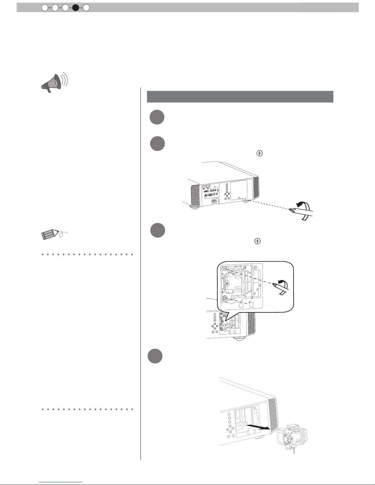
60
Maintenance
4
Replacing the Lamp
The lamp is a consumable item. If the image is dark or the lamp is turned off, replace the lamp
unit.
● When the lamp replacement time approaches, a message is displayed on the screen and the condition
is indicated by the indicator. (Reference page: 16 to 17, 67)
CAUTION
●
Do not insert your hands into
the opening of the lamp!
This could cause obvious
deterioration of the
equipment’s function, wounds
and electric shocks.
●
Do not replace the lamp
immediately after the unit has
been used, and allow a cooling
period of 1 hour or more before
replacement. The temperature
of the lamp is still high and this
may cause a burn.
●
Do not apply shock to the
lamp unit. I
t may cause lamp
blowout.
●
Do not use ammable air duster
to clean the internal parts of the
unit. This may cause re.
Lamp replacement procedure
MEMO
Usable Lamp Life
Purchasing the Lamp Unit
●
When using the “Lamp Power”
set at “Normal", the lifetime of
the lamp will be approximately
3000 hours.
This is an average lifetime and
cannot be guaranteed.
●
The lamp life may not reach
3000 hours depending on the
operating conditions.
●
When the lamp has reached
the end of its usable life,
deterioration progresses
rapidly.
●
If the picture becomes dark,
the tint becomes strange, or
the image ickers, promptly the
lamp unit for a new one.
Please consult your authorized
dealer.
■
Lamp Unit
Part No.: PK-L2210U
2
Remove the lamp cover
Loosen the screws on the lamp unit
●
Remove the screws with a
screwdriver.
●
Loosen the screws with a screwdriver.
3
4
Pull out the lamp unit
●
Grasp the handle and pull out the lamp unit.
Handle
1
Remove the power plug from the
outlet
Page 48

61
Maintenance
ENGLISH
Install the new lamp unit
Tighten the screws of the new lamp
unit
Attach the lamp cover
CAUTION
●
Use only genuine replacement
parts for the lamp unit. Also,
never attempt to reuse an old
lamp unit. This may cause a
malfunction.
●
Do not touch the surface of a
new lamp. This may shorten
the lamp life and cause lamp
blowout.
MEMO
After Replacing the Lamp
●
Do not place the removed
lamp unit at locations that is
reachable by children or near
combustible items
.
●
Dispose used lamp units in
the same way as uorescent
lamps. Follow your local
community rules for disposal.
5
6
●
Tighten the screws with a screwdriver.
●
Insert the top part (with 2 claws) of the lamp cover into
the unit.
●
Fasten the screws with a screwdriver.
7
Handle
Page 49

62
Maintenance
4
Replacing the Lamp (Continued)
Resetting lamp Time
After replacing a new lamp unit, please reset the lamp time.
Description of two methods.
● Select
“
Yes” and the lamp time is set to zero. Moreover,
one returns to the previous menu.
Reset the lamp time from the menu screen.
1
2
3
BACK
HIDE
LIGHT
LENS AP.
C.M.D
PC
HDMI 1
STAND BY
ASPECT
HDMI 2
ANAMO
COMP.
LENS.
CONTROL
MENU
GAMMA
P.FILE
COLOR
ADJ.
PIC.
ON
FILM
NATURAL
STAGE 3D
USER1
USER2
THX
ANIME
CINEMA
PICTURE MODE
INPUT
TEMP
COLOR
MENU
Picture Adjust
Reset
Advanced
Exit
MENU
BACK
Back
Select
Operate
Color Temp.
Gamma
Film Tone
Contrast
Brightness
Color
Tint
0
0
0
0
Color Profile
Picture Mode
Film
Film1
Xenon1
Film1
Display the setting menu
Select“Function” “Lamp Reset”
Exit
MENU
BACK
Back
Select
Operate
Trigger
Off Timer
Communication Terminal
Network
High Altitude Mode
LAN
Off
Off
Off
Function
Lamp Reset
Reset Lamp Time?
YES
NO
Re-conrm
② Confirm
① Select
Page 50

63
Maintenance
ENGLISH
WARNING
LAMP
STANDBY/ON
CAUTION
●
Reset the lamp time only when
you have replaced the lamp.
●
Never reset the service time when
the lamp is still in use. Otherwise,
the approximate standard for
gauging replacement time may be
inaccurate and lamp blowout may
occur.
BACK
HIDE
LIGHT
LENS AP.
C.M.D
PC
HDMI 1
STAND BY
ASPECT
HDMI 2
ANAMO
COMP.
LENS.
CONTROL
MENU
GAMMA
P.FILE
COLOR
ADJ.
PIC.
ON
FILM
NATURAL
STAGE 3D
USER1
USER2
THX
ANIME
CINEMA
PICTURE MODE
INPUT
TEMP
COLOR
X7 X9
Reset the lamp time by remote control.
1
2
Insert the power plug to the power
outlet
Red Lights
Must operate with the remote
control in the standby mode (the
projector is powered, but is not
turned on).
●
Press in the order as shown.
●
Press each button within 2-second intervals and press
the last button for 2 seconds or more.
HIDE
BACK
OK
Press for 2 seconds or more
●
[STANDBY/ON] indicator and [LAMP] indicator blink
alternately for 3 seconds. After that, the unit switches to
standby mode.
Page 51

64
Maintenance
4
Method for cleaning and
replacing lters
Clean the filter regularly or air intake efficiency may deteriorate and malfunction may
occur.
Remove the inner lter.
1
2
Clean the lter.
●
Wash the lter with water and dry it in a shaded area.
●
In extremely soiled cases, using a neutral detergent
is recommended. Put on rubber gloves when using a
neutral detergent.
●
After washing the lter with water, make sure that it is
completely dry before reinstalling. Otherwise electric
shock or malfunctions may occur.
●
Do not clean the lter with a vacuum cleaner or air
duster. The lter is soft and may be damaged.
Reinstall the inner lter.
3
CAUTION
●
Pull the power plug from the
power outlet.
●
Please turn this unit and if
you put in on a bed or a table,
rst place something soft
like a piece of cloth below.
Then you can put it on top of
it. Otherwise, it may cause
scratches on this unit.
If the lter is damaged or
too dirty to be cleaned.
MEMO
●
Replace with a new lter. A
dirty lter will dirty the internal
parts of the unit and cause
shadows on the video image.
●
To purchase a new lter or
when it is dirty in the internal
parts, consult your authorized
dealer.
■
Inner Filter
Part No.:
●
Replacement Filter:
PC010661199
Lift up while pushing the claw
Check that the left and
right claws are locked onto
the unit
Page 52

Others
65
ENGLISH
Troubleshooting
■
You do not need to worry about the following situations if there is no abnormality on the
screen.
●
Part of the top surface or front of the unit is hot.
●
A creaking sound is heard from the unit.
●
An operating sound is heard from the inside of the unit.
●
Color smear occurs on some screens.
■
Perform the following operations when the unit is unable to operate normally due to external
static or noise.
① When the unit is in standby mode, please pull out the power plug, then insert again.
② Press the power button on the unit to turn on the power again.
■
A sound may be heard when the lamp is off but there is no danger.
■
D-ILA device is manufactured using high-precision technology but there may be some missing
pixels or pixels that remain permanently lit up.
Power is not supplied
Is the power cord disconnected? Insert the power cord (plug) rmly.
Reference page:
31
Is the lamp cover properly shut?
Remove the power plug when the unit is
in standby mode and close the lamp cover
properly. After that, insert the plug again.
Reference page:
61
Is the lamp in Cool Down
mode?
After the Cool Down mode is complete, turn
on the power again.
Reference page:
33
Video image does not appear
Is the correct external input
selected?
Select the correct external input.
Reference page:
32
Is the AV device properly
connected?
Connect the AV device properly.
Reference page:
25 to 30
Is the power of the AV device
turned on?
Turn on the power of the AV device and play
the video.
Reference page:
32
Are the correct signals being
output from the AV device?
Set the AV device prope
rly.
Reference page:
25 to 30
Is the setting of the input
terminal correct?
Set “COMP.” and “HDMI” in the setting menu
according to the input signal.
Reference page:
51 to 52
Is the video image temporarily
hidden?
Press the [HIDE] button to display the video
image again.
Reference page:
36
Remote control does not work
Are batteries installed
correctly?
Match the polarities (
or ) correctly when
inserting the batteries.
Reference page:
19
Are batteries exhausted? Replace with new batteries.
Reference page:
19
Is there an obstructive object
between the remote control
and remote sensor?
Remove any obstructive objects.
Reference page:
23
Is the remote control held too
far away from the unit?
Hold the remote control closer to the sensor
when using.
Reference page:
23
Before sending the unit to your authorized dealer for repair, please
check the following points.
The following situations are not malfunctions.
Page 53
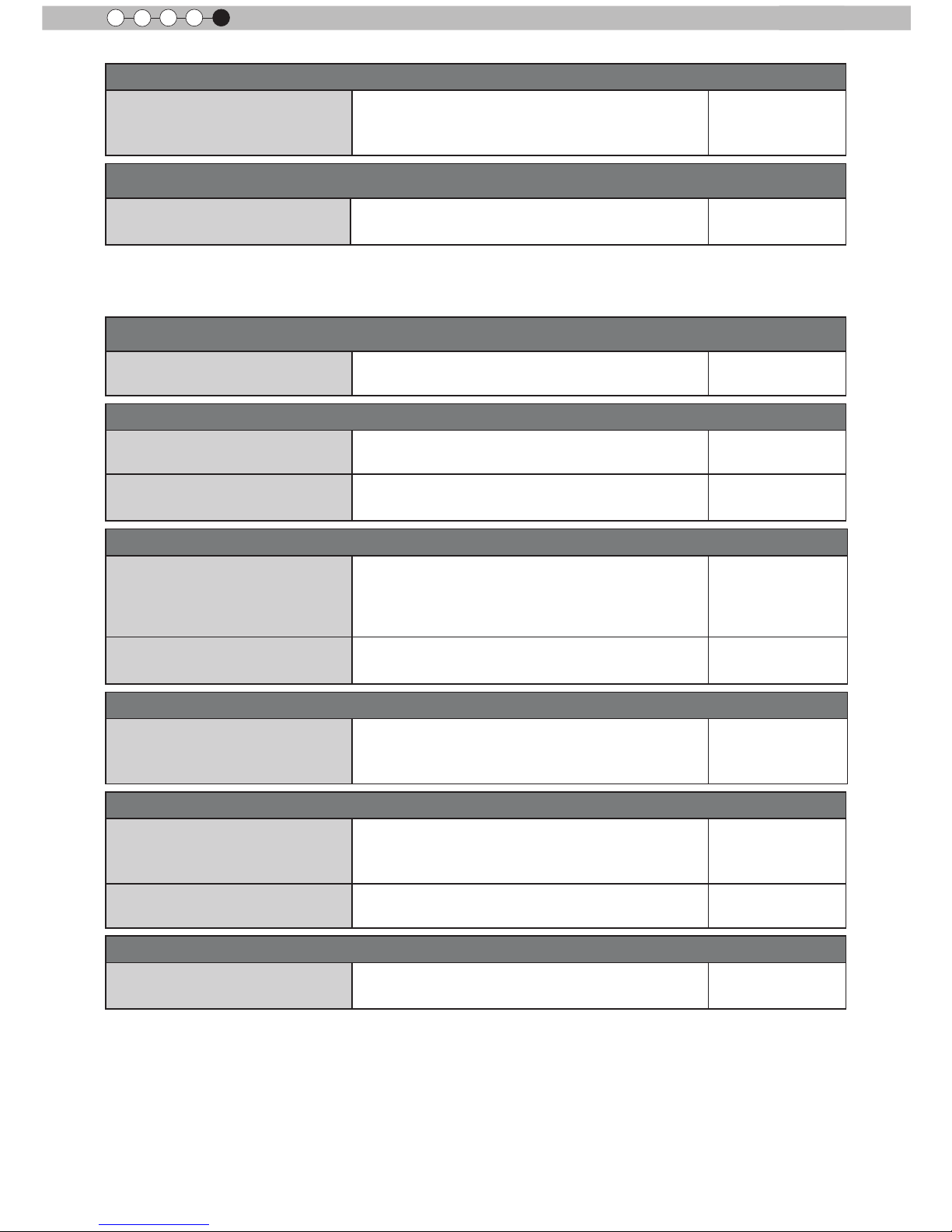
66
Others
5
The picture cannot be projected
Will the picture icker and
become invisible with HDMI
input?
Please use a short HDMI cable.
Reference page:
26
The image cannot output by HDMI terminal
Is the setup of “Control with
HDMI” function “Off”?
Set up the “Control with HDMI” function to “Off”.
Reference page:
51
Color does not appear or looks strange
Is the image correctly adjusted?
Adjust “Color” and “Tint” in the setting menu.
Reference page:
47
Video image is fuzzy
Is the focus correctly adjusted? Adjust the focus.
Reference page:
32
Is the unit placed too near or too
far away from the screen?
Set the unit at a correct distance from the
screen.
Reference page:
21, 23
Video images are missing
Has setting been performed for
screen mask?
Set “Mask” in the setting menu to “Off”.
Reference page:
35
Reference page:
51
Is the display out of position?
Alter the “Picture Position” value in the setting
menu to ensure that images are not missing.
Reference page:
50
Projected image is dark
Is the lamp near exhaustion?
Check the lamp time on the information menu.
Prepare a new lamp unit or replace as soon
as possible when the lamp is near exhaustion.
Reference page:
60 to 63
The unit works when power is turned on but stops abruptly after a few minutes
Are the air inlets and exhaust
vent blocked?
Remove the power plug when the unit is in
standby mode and remove any blocking object.
After that, insert the plug again.
Reference page:
3, 14
Is the lter dirty? Clean the lter.
Reference page:
64
Power is cut off suddenly
Has setting been performed for
off timer?
Set “Off Timer” in the setting menu to “Off”.
Reference page:
54 to 55
● Even if the “Control with HDMI” function is “On”, there are still some devices cannot reveal image
normally.
Page 54

Others
67
ENGLISH
In case this message is
displayed
Message Cause (Details)
COMP㧚
䇭NO Input
No device is connected to the input terminal.
The input terminal is connected but there is no signal.
Input the video signals.
COMP.
A video signal that cannot be used in this unit has been input.
Input video signals that can be used.
* The names of input terminals such as COMP. will be displayed in yellow
BACK
Back
Lamp replacement
This message is displayed when the accumulated lamp time has
exceeded 2900 hours.
To clear the message, press the [Back] button.
Get ready a new lamp unit and replace as soon as possible. Reset
the lamp time after replacing the lamp. (Reference page: 60 to 63)
Page 55

68
Others
5
RS-232C Interface
It is possible to control this machine, if it is connected by an RS-232C cross cable (D-Sub9
pin) to a PC. Otherwise, this machine can be controlled via a computer network by connecting
it with a LAN cable and sending of control commands. Please use it after you have understood
this by reading professional books, or by discussing it with a system administrator.
Before you can con
trol it via LAN, you have to establish a TCP-connection via a "3-way-handshake". It is
necessary for a connection authentication to send from the projector "PJ_OK" and - within 5 seconds after
sending a "PJREQ" – to receive "PJACK". Please perform this operation – after conrming the operating
status of the projector - again after establishment of a TCP connection, if you cannot send within 5 seconds
"PJ_NG" or could not receive "PJNAK".
RS-232C Specications
Pin No. Signal Function Signal Direction
2 RxD
Receive data PC→This unit
3 TxD
Transmit data This unit→PC
5 GND
Signal ground
-
1,4,6 - 9 N/C - -
Mode
Non-synchronous
Character Length
8 bit
Parity
None
Start Bit
1
Stop Bit
1
Data rate
19200 bps
Data format
Binary
This unit
Start Bit
Stop Bit
D6 D7D4 D5D2 D3D0 D1
●
PC refers to the controller such as a personal computer.
TCP/IP-connection
Control PC
Projector
PJ_OK
PJREQ
PJACK
Connection authentication procedure
Within 5 seconds
Projector Control
TCP-layer connection establishment
TCP port number 20554
Three-way handshake
Page 56
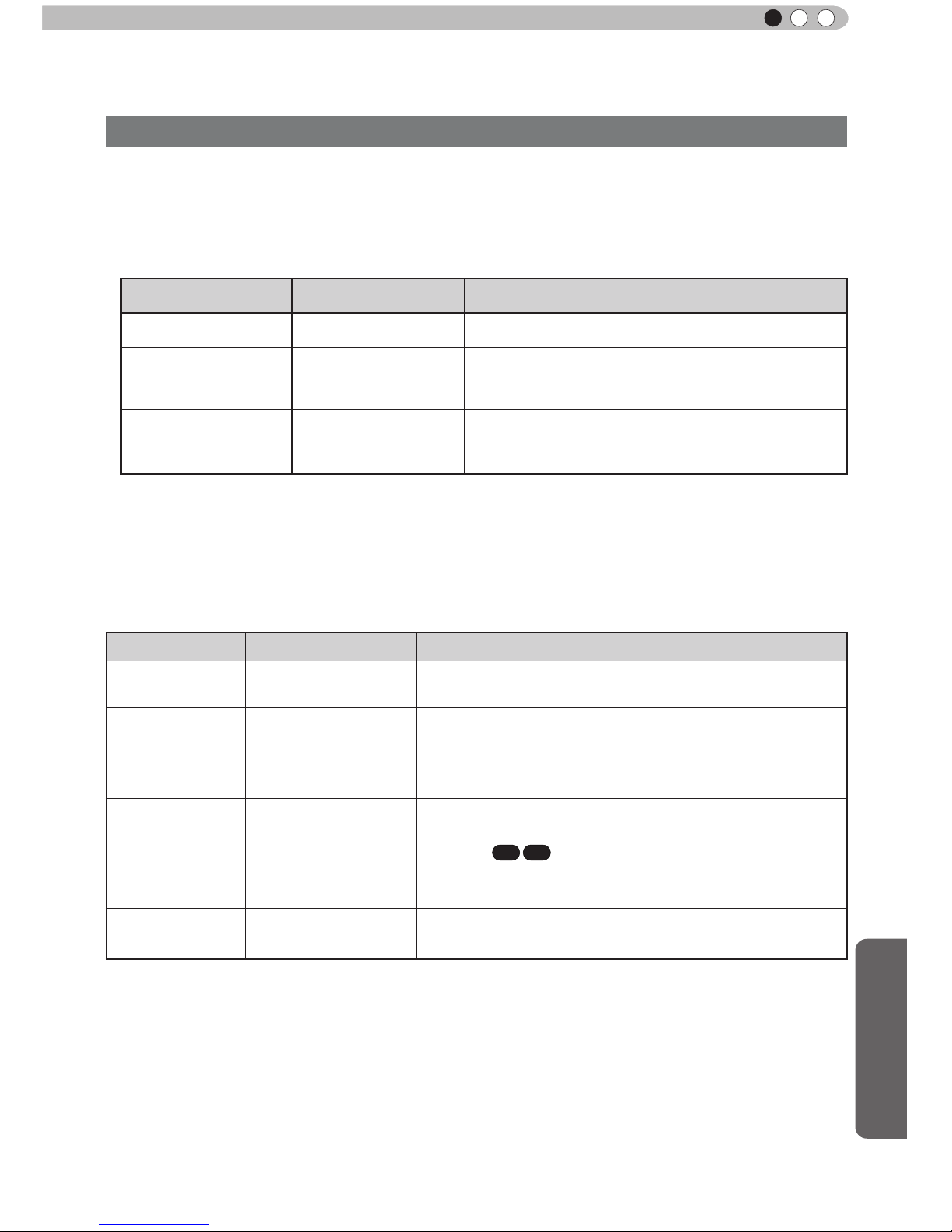
Others
69
ENGLISH
RS-232C Interface (Continued)
The command between this unit and the computer consists of “Header”, “Unit ID”, “Command”, “Data”
and “End”.
●
Header (1 byte), Unit ID (2 bytes), Command (2 bytes), Data (n bytes), End (1 byte)
■
Header
This binary code indicates the start of communication.
Binary code
Type Description
21 Operating command PC → This unit
3F Response command PC → This unit
40 Reference command This unit → PC
06 ACK
This unit → PC
(When the command is accepted without error, it
returns to PC)
■
Unit ID
This code species the unit. The binary code is xed at “8901”.
■
Command and data
Operating command and data (Binary code)
Command Type Description
0000
Connection check
Check whether communication is available between this
unit and the PC during standby.
5057
Power supply
During standby
31: Turn on the power.
During power on
30: Turn off the power. (Standby mode)
4950
Input
During power on
32: COMP.
33: PC
X7 X9
36: HDMI 1
37: HDMI 2
5243
Remote Control
Sends the same code as the supplied remote control.
●
“Remote control code” (Reference page: 70)
Command Format
Page 57

70
Others
5
Reference command and data (Binary code)
Command Type Data description
5057
Power supply
During standby or power on
30: Standby mode
31: Power-on mode
32: During Cool Down mode
34: Warning mode
4950
Input
During power on
32: COMP.
32: PC
X7 X9
36: HDMI 1
37: HDMI 2
■
End
This code indicates the end of communication. The binary code is xed at
“0A”.
■
Remote control code
●
Binary code is sent during communication.
Remote control button
name
Binary code
Remote control button
name
Binary code
37 33 30 31 NATURAL 37 33 36 41
37 33 30 32 USER 1 37 33 36 43
BACK 37 33 30 33 USER 2 37 33 36 44
ON 37 33 30 35
USER 3
X3
37 33 36 45
STAND BY 37 33 30 36
THX
X7 X9
37 33 36 46
HIDE 37 33 31 44 HDMI 1 37 33 37 30
LENS.AP. 37 33 32 30 HDMI 2 37 33 37 31
MENU 37 33 32 45 PIC.ADJ. 37 33 37 32
OK 37 33 32 46 INFO. 37 33 37 34
LENS CONTROL 37 33 33 30 GAMMA 37 33 37 35
37 33 33 34 C.TEMP 37 33 37 36
37 33 33 36 ASPECT 37 33 37 37
PC
X7 X9
37 33 34 36 3D 37 33 38 37
COMP. 37 33 34 44
COLOR PROFILE
X7 X9
37 33 38 38
ANIME 37 33 36 36 C.M.D 37 33 38 41
STAGE 37 33 36 37
ANAMO
X3
37 33 43 35
CINEMA 37 33 36 38 COLOR SPACE 37 33 43 44
FILM 37 33 36 39
X3
Page 58
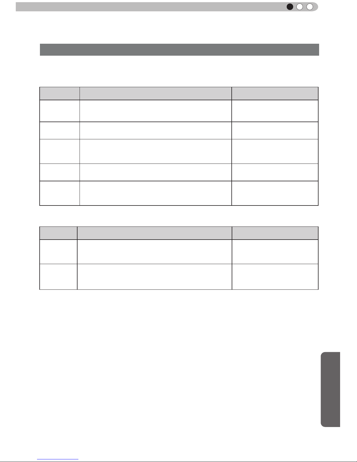
Others
71
ENGLISH
This section shows the communication examples of RS-232C.
■
Operating command
Type Command Description
Connection
check
PC→This unit: 21 89 01 00 00 0A
This unit→PC:
06 89 01 00 00 0A
Connection check.
Power (On)
PC→This unit: 21 89 01 50 57 31 0A
This unit→PC:
06 89 01 50 57 0A
When power is turned on from
standby mode.
Power (Off)
PC→This unit: 21 89 01 50 57 30 0A
This unit→PC: 06 89 01 50 57 0A
When power is turned off
(standby mode) from power-on
mode.
Input
(COMP.)
PC→This unit: 21 89 01 49 50 32 0A
This unit→PC: 06 89 01 49 50 0A
When video input is set to
component.
Remote
Control
(MENU)
PC→This unit: 21 89 01 52 43 37 33 32 45 0A
This unit→PC:
06 89 01 52 43 0A
When the same operation as
pressing the [MENU] button
on the remote control is made
■
Reference command
Type Command Description
Power (On)
PC→This unit: 3F 89 01 50 57 0A
This unit→PC: 06 89 01 50 57 0A
This unit→PC: 40 89 01 50 57 31 0A
When information of poweron mode is acquired.
Input
(HDMI 1)
PC→This unit: 3F 89 01 49 50 0A
This unit→PC: 06 89 01 49 50 0A
This unit→PC: 40 89 01 49 50 36 0A
When information of HDMI 1
input is acquired.
RS-232C Interface (Continued)
RS-232C Communication Examples
Page 59

72
Others
5
Caution
Copyright and Caution
D-ILA Device Characteristics
Do not project still pictures or pictures that have still
segments for a long period of time. The still parts of
the picture may remain on the screen.
Take special notice of images on the screens of
video games and computer programs. There is no
problem when playing normal video images such as
movies.
When Unit is Unused for a Long Time
Prolonged disuse of the unit may effect an error on the
functions. Turn on the power occasionally and operate
the unit.
Usage Environment
●
Avoid direct exposure of screen to direct sunlight
and illumination. Block light using a curtain.
Images can be well projected by darkening the
brightness of the room.
●
Do not use this unit in rooms with cigarette
smoke or oily smoke. This may cause the unit
to malfunction.
Parts Replacement
This unit contains parts (optical part, cooling
fan, etc.) that require replacement to maintain
its functioning. The estimated time for parts
replacement varies greatly depending on the
usage and environment. Please consult your
authorized dealer for replacement.
Maintenance Procedures
Dirt on the cabinet
●
Gently clean dirt on the cabinet with a soft cloth.
In the case of heavy soiling, soak a cloth in water,
wring dry and wipe, followed by wiping again with
a dry cloth. Pay attention to the following as the
cabinet may deteriorate in condition or paint may
come off.
● Do not wipe with thinner or benzene.
● Do not spray with volatile chemicals like
insecticide.
● Do not allow prolonged contact with rubber or
plastic products.
Dirt in the air inlets
●
Use a vacuum cleaner to suck up the dirt.
Otherwise, use a cloth to wipe off the dirt. If dirt
is allowed to accumulate in the air inlets, the
internal temperature cannot be adjusted and this
may cause a malfunction.
Dirt on the lens
●
Clean the dirt using commercial blowers or
lens cleaning papers for cleaning glasses and
cameras. Do not use uid-type cleaning agents.
This may lead to peeling of the surface coating
lm.
( Reference page: 14)
About Trademarks and Copyright
●
HDMI, HDMI logo and high denition multimedia interface
are trademarks or registered trademarks of HDMI Licensing
LCC.
Page 60

Others
73
ENGLISH
Product Name
D-ILA
Projector
Model Name
DLA-X3-W, DLA-X3-B, DLA-X7-B, DLA-X9-B *1
Display Panel/Size
D-ILA
device
* 2 *3
0.7
" (1920pixels x 1080pixels) x 3 (Total no. of pixels: Approx. 6.22million)
Projection Lens
2.0 x power zoom lens (1.4:1 to 2.8:1)
(Zoom/Focus: Power)
Light-source Lamp
220 W Ultra-high pressure mercury lamp [Part No. :
PK-L2210U]
Average lifespan:
3000
hours (normal mode)
Screen Size
Approx. 60" to 200" (Aspect ratio: 16:9)
Projection Distance Approx.
1.8m to 12m
Analog Video Input
Format
480i, 480p, 576i, 576p, 720p/50 Hz, 720p/60 Hz, 1080i/50
Hz
1080i/60
Hz
Digital Video Input
Format
480i, 480p, 576i, 576p, 720p/50 Hz, 720p/60 Hz, 1080i/50
Hz
1080i/60 Hz, 1080p/24 Hz, 1080p/50 Hz, 1080p/60 Hz
PC compatible signals
(Reference page: P24)
Resolution 1920 dots x 1080 dots
Input terminal
Video Input
1 system, RCA
pin jack
×
3
Y:1.0V
p-p, 75Ω
P
b/Cb, Pr/Cr:0.7Vp-p, 75Ω
*
Also supports R / G / B Sync on G
HDMI
Input
2 system, HDMI 19
pin
×
2(HDCP
compliant
) * 4
Compatible with the HDMIv1.4a standard
* 5
PC
Input
1 system, D-Sub 15 pin VGA
Output terminal
Trigger terminal
1 system, Φ3.5mmDC Power Jack (
)
DC OUT 12V, 0.1A
3D synchro
3D synchro emitter dedicated terminal (1 system, mini DIN 3pin)
Control terminal
RS-232C terminal 1 system , D-sub 9-pin (male) x1 (External control)
Remote terminal 1 system, stereo mini jack x1 (Remote Control)
LAN terminal 1 system, RJ-45 plug x1
Power Requirements
AC 110V-240V 50/60Hz
Power Consumption
350W(3.5A) (
Standby mode:
0.9W)
Operation Environment
Temperature:
5ºC to 35ºC
Humidity: 20% to 80%(No condensation)
(Storage Temperature:
-10℃ to 60℃ )
Installation Height
Below
5000ft (1524 m)
Dimensions
(Width x Height x Depth)
About 455mmx179mmx472mm
(
Excluding foot, lens, and other protruding parts)
Mass
14.7kg
X3
/ 15.1kg
X7 X9
Accessories
(Please see page 13)
Specifications
Page 61

74
Others
5
* 1
Regarding -W the color of the main body is some kind of white color. Regarding –B, the color of the
main body is some kind of black.
* 2
D-ILA is the abbreviation for Direct drive Image Light Amplier.
* 3 D-ILA devices are manufactured using extremely high-precision technology. Pixel effectiveness is
99.99%. Only 0.01% or less of the pixels are either missing or would remain permanently lit up.
* 4 HDCP is the abbreviation for High-bandwidth Digital Conte
nt Protection system.
The image of HDMI input terminal may not be displayed due to HDCP specication change.
* 5 Ethermet is not supported.
●
Design and specications are subject to change without prior notice.
●
Please note that some of the pictures and illustrations may have been abridged, enlarged or
contextualized in order to aid comprehension. Images may differ from the actual product.
Page 62
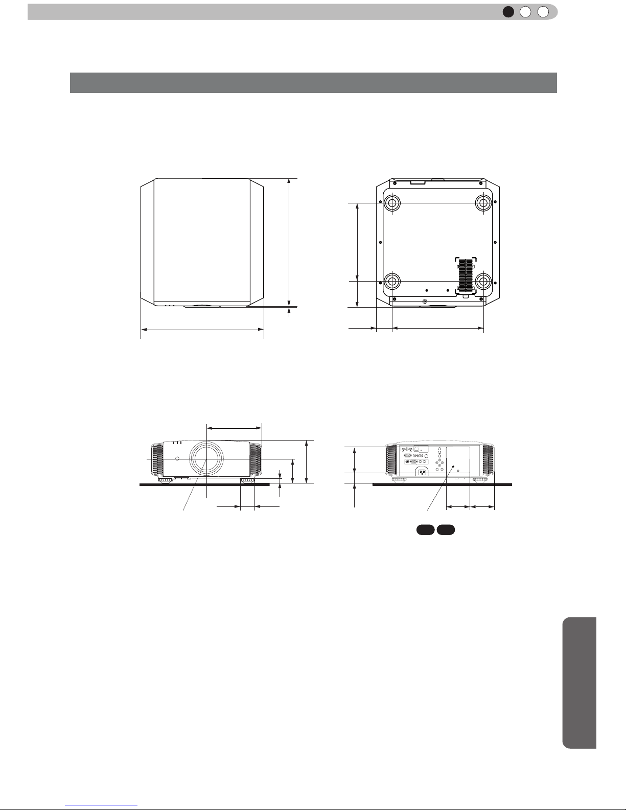
Others
75
ENGLISH
Dimensions
(Unit: mm)
455
5
337
59
227.5
Φ60
24
103.5
178.5
290
472
91
110
32
110
92
Lens center
Lamp cover
■
■
■■
Top Surface
Front
Bottom Surface
Back Surface
Connection terminal section of the
illustration is
X7 X9
.
 Loading...