

Page 1
Operation
Others
Preparation
Getting Started
Maintenance
0711TTH-AO-AO
© 2011 JVC KENWOOD Corporation
DLA-X90R
DLA-X70R
DLA-X30
D-ILA PROJECTOR
PROYECTOR D-ILA
PROJECTEUR D-ILA
For Customer use :
Enter below the serial No. which is
located on the side of the cabinet.
Retain this information for future
reference.
Model No. DLA-X70R
DLA-X30
DLA-X90R
Serial No.
Pour utilisation par le client :
Entrer ci-dessous le N° de série qui
est situé sous le boîtier. Garder
cette information comme référence
pour le futur.
N° de modèle DLA-X70R
DLA-X30
DLA-X90R
N° de série
Instrucción para el cliente :
Introduzca a continuación el nº de
serie que aparece en la parte
inferior lateral de la caja. Conserve
esta información como referencia
para uso ulterior.
Modelo Nº DLA-X70R
DLA-X30
DLA-X90R
Nº de serie
DLA-X90R/DLA-X70R/DLA-X30
ENGLISH FRANÇAIS ESPAÑOL/CASTELLANO
INSTRUCTIONS
MANUEL D’INSTRUCTIONS
MANUAL DE INSTRUCCIONES
D-ILA PROJECTOR
PROJECTEUR D-ILA
PROYECTOR D-ILA
DLA-X90R
DLA-X70R
DLA-X30
ON
STAND BY
COMPONENT
.
COMP
HDMI 1
HDMI 2
ASPECT
INFO.
ANAMO
LENS
LENS AP.
C.M.D
CONTROL
HIDE
LIGHT
BACK
MENU
CINEMA
OINEMA
ANIME
FILM
NATURAL
STAGE 3D
USER2 USER3
USER1
C.TEMP.
C.SPACE
GAMMA
PIC.ADJ.
COLOR
PICTURE
COLOR
SPACEADJUST
TEMP.
90
70
PC021082599-1
Page 2
1
Getting started
Safety Precautions
IMPORTANT INFORMATION
This product has a High Intensity Discharge (HID) lamp that contains
mercury.
Disposal of these materials may be
regulated in your community due to
environmental considerations. For
disposal or recycling information,
please contact your local authorities or
for USA, the Electronic Industries
Alliance: http://www.eiae.org.
WARNING:
TO PREVENT FIRE OR SHOCK HAZARDS, DO
NOT EXPOSE THIS APPLIANCE TO RAIN OR
MOISTURE.
WARNING:
THIS APPARATUS MUST BE EARTHED.
CAUTION:
To reduce the risk of electric shock, do not remove
cover. Refer servicing to qualied service personnel.
This projector is equipped with a 3-blade grounding
type plug to satisfy FCC rule. If you are unable to
insert the plug into the outlet, contact your
electrician.
MACHINE NOISE INFORMATION
(Germany only)
Changes Machine Noise Information Ordinance 3.
GSGV, January 18, 1991: The sound pressure level
at the operator position is equal or less than 20 dB
(A) according to ISO 7779.
For the customers in Taiwan only
廢電池請回收
FCC INFORMATION (U.S.A. only)
CAUTION:
Changes or modication not approved by JVC
could void the user’s authority to operate the
equipment.
NOTE:
This equipment has been tested and found to
comply with the limits for Class B digital devices,
pursuant to Part 15 of the FCC Rules. These
limits are designed to provide reasonable protec
tion against harmful interference in a residential
installation. This equipment generates, uses, and
can radiate radio frequency energy and, if not
installed and used in accordance with the instruc
tions, may cause harmful interference to radio
communications. However, there is no guarantee
that interference will not occur in a particular
installation. If this equipment does cause harmful
interference to radio or television reception, which
can be determined by turning the equipment off
and on, the user is encourage to try to correct the
interference by one or more of the following
measures:
● Reorient or relocate the receiving antenna.
● Increase the separation between the equipment
and receiver.
● Connect the equipment into an outlet on a
circuit different from that to which the receiver is
connected.
● Consult the dealer or an experienced radio/
TV technician for help.
About the installation place
Do not install the projector in a place that cannot
support its weight securely.
If the installation place is not sturdy enough, the
projector could fall or overturn, possibly causing
personal injury.
IMPORTANT SAFEGUARDS
Electrical energy can perform many useful
functions. This unit has been engineered and
manufactured to assure your personal safety. But
IMPROPER USE CAN RESULT IN POTENTIAL
ELECTRICAL SHOCK OR FIRE HAZ ARD.
In order not to defeat the safeguards incorporated
into this product, observe the following basic rules
for its installation, use and service. Please read
these Important Safeguards carefully before use.
- All the safety and operating instructions should
be read before the product is operated.
- The safety and operating instructions should be
retained for future reference.
2
Page 3
Getting Started
ENGLISH
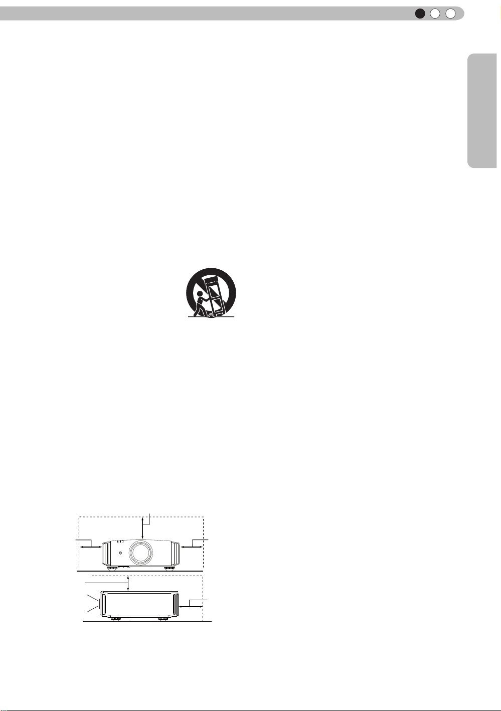
150 mm and above
300 mm
and above
200 mm
and above
300 mm
and above
150 mm
and above
PORTABLE CART WARNING
(symbol provided by RETAC)
S3126A
- All warnings on the product and in the operating
instructions should be adhered to.
- All operating instructions should be followed.
- Place the projector near a wall outlet where the
plug can be easily unplugged.
- Unplug this product from the wall outlet before
cleaning. Do not use liquid cleaners or aerosol
cleaners. Use a damp cloth for cleaning.
- Do not use attachments not recommended by the
product manufacturer as they may be hazardous.
- Do not use this product near water. Do not use
immediately after moving from a low temperature
to high temperature, as this causes condensation,
which may result in re, electric shock, or other
hazards.
- Do not place this product on an unstable cart,
stand, or table. The product may fall, causing
serious injury to a child or adult, and serious
damage to the product. The product should be
mounted according to the manufacturer’s
instructions, and should use a mount recommend
ed by the manufacturer.
- When the product is used on a
cart, care should be taken to avoid
quick stops, excessive force,
and uneven surfaces which may
cause the product and cart to
overturn, damaging equipment or
causing possible injury to the
operator.
- Slots and openings in the cabinet are provided for
ventilation. These ensure reliable operation of the
product and protect it from overheating. These
openings must not be blocked or covered. (The
openings should never be blocked by placing the
product on bed, sofa, rug, or similar surface. It
should not be placed in a built-in installation such
as a bookcase or rack unless proper ventilation is
provided and the manufacturer’s instructions have
been adhered to.)
- To allow better heat dissipation, keep a clearance
between this unit and its surrounding as shown
below. When this unit is enclosed in a space of
dimensions as shown below, use an air-conditioner
so that the internal and external temperatures are
the same. Overheating can cause damage.
Front
- power source indicated on the label. If you are
not sure of the type of power supply to your
home, consult your product dealer or local
power company.
- This product is equipped with a three-wire plug.
This plug will t only into a grounded power
outlet. If you are unable to insert the plug into
the outlet, contact your electrician to install the
proper outlet. Do not defeat the safety purpose
of the grounded plug.
- Power-supply cords should be routed so that
they are not likely to be walked on or pinched
by items placed upon or against them. Pay
particular attention to cords at doors, plugs,
receptacles, and the point where they exit from
the product.
- For added protection of this product during a
lightning storm, or when it is left unattended and
unused for long periods of time, unplug it from
the wall outlet and disconnect the cable system.
This will prevent damage to the product due to
lightning and power line surges.
- Do not overload wall outlets, extension cords, or
convenience receptacles on other equipment as
this can result in a risk of re or electric shock.
- Never push objects of any kind into this product
through openings as they may touch dangerous
voltage points or short out parts that could result
in a re or electric shock. Never spill liquid of
any kind on the product.
- Do not attempt to service this product yourself
as opening or removing covers may expose you
to dangerous voltages and other hazards. Refer
all service to qualied service personnel.
- Unplug this product from the wall outlet and
refer service to qualied service personnel
under the following conditions:
a) When the power supply cord or plug is damaged.
b) If liquid has been spilled, or objects have fallen on
the product.
c) If the product has been exposed to rain or water.
d) If the product does not operate normally by
following the operating instructions. Adjust only
those controls that are covered by the Operation
Manual, as an improper adjustment of controls may
result in damage and will often require extensive
work by a qualied technician to restore the product
to normal operation.
e) If the product has been dropped or damaged in any
way.
f ) When the product exhibits a distinct change in
performance, this indicates a need for service.
- When replacement parts are required, be sure
the service technician has used replacement
parts specied by the manufacturer or with
same characteristics as the original part.
Unauthorized substitutions may result in re,
electric shock, or other hazards.
- Upon completion of any service or repairs to
this product, ask the service technician to
perform safety checks to determine that the
product is in proper operating condition.
3
Page 4

1
Getting started
- The product should be placed more than one foot
away from heat sources such as radiators, heat
registers, stoves, and other products (including
ampliers) that produce heat.
- When connecting other products such as VCR’s,
and DVD players, you should turn off the power of
this product for protection against electric shock.
- Do not place combustibles behind the cooling fan.
For example, cloth, paper, matches, aerosol cans
or gas lighters that present special hazards when
over heated.
- Do not look into the projection lens while the
illumination lamp is turned on. Exposure of your
eyes to the strong light can result in impaired
eyesight.
- Do not look into the inside of this unit through
vents (ventilation holes), etc. Do not look at the
illumination lamp directly by opening the cabinet
while the illumination lamp is turned on. The
illumination lamp also contains ultraviolet rays and
the light is so powerful that your eyesight can be
impaired.
- Do not drop, hit, or damage the light-source lamp
(lamp unit) in any way. It may cause the light source lamp to break and lead to injuries. Do not
use a damaged light source lamp. If the light source lamp is broken, ask your dealer to repair it.
Fragments from a broken light-source lamp may
cause injuries.
- The light-source lamp used in this projector is a
high pressure mercury lamp. Be careful when
disposing of the light-source lamp. If anything is
unclear, please consult your dealer.
- Do not ceiling-mount the projector to a place which
tends to vibrate; otherwise, the attaching xture of
the projector could be broken by the vibration,
possibly causing it to fall or overturn, which could
lead to personal injury.
- Use only the accessory cord designed for this
product to prevent shock.
- For health reasons, please take a break of about
5-15 minutes every 30-60 minutes and let your
eyes rest. Please refrain from watching any 3D images when you feel tired, unwell or if you feel
any other discomfort. Moreover, in case you see a
double image, please adjust the equipment and
software for proper display. Please stop using the
unit if the double image is still visible after
adjustment.
- Once every three years, please perform an internal
test. This unit is provided with replacement parts
needed to maintain its function (such as cooling
fans). Estimated replacement time of parts can
vary greatly depending on frequency of use and
the respective environment. For replacement,
please consult your dealer, or the nearest
authorized JVC service center.
- When xing the unit to the ceiling, Please note that
we do not take any responsibility, even during the
warranty period, if the product is damaged due to
use of metal xtures used for xation to the ceiling
other than our own or if the installation
environment of said metal xtures is not
appropriate. If the unit is suspended from the
ceiling during use, please be careful in regard to
the ambient temperature of the unit. If you use
a central heating, the temperature close to the
ceiling will be higher than normally expected.
- Video images can burn into the electronic com
ponent parts. Please do not display screens with
still images of high brightness or high contrast,
such as found in video games and computer
programs. Over a long period of time it might
stick to the picture element. There is no problem
with the playback of moving images, e.g. normal
video footage.
- Not using the unit for a long time can lead to
malfunction. Please power it on and let it run
occasionally. Please avoid using the unit in a
room where cigarettes are smoked. It is impos
sible to clean optical component parts if they are
contaminated by nicotine or tar. This might lead
to performance degradation.
- Please watch from a distance three times the
height of the projected image size. Persons with
photosensitivity, any kind of heart disease, or
weak health should not use 3D glasses.
- Watching 3D-images might be cause of illness.
If you feel any change in your physical condition,
please stop watching immediately and consult a
physician if necessary.
- When watching 3D images, it is recommended
to take regular breaks. As the length and
frequency of the required breaks differ for every
person, please judge according to your own
condition.
- If your child watches while wearing 3D glasses,
it should be accompanied by its parents or an
adult guardian. The adult guardian should be
careful to avoid situations where the child’s eyes
might become tired, as responses to tiredness
and discomfort, etc., are hard to detect, and it is
possible for the physical condition to deteriorate
very quickly. As the visual sense is not yet fully
developed in children under the age of 6, please
consult a physician in regard to any problem
concerning 3D-images if necessary.
- Note that when using the 3D feature, the video
output may appear different from the original
video image due to image conversion on the
device.
DO NOT allow any unqualied person
*
to install the unit.
Be sure to ask your dealer to install the unit
(e.g.attaching it to the ceiling) since special
technical knowledge and skills are required
for installation. If installation is performed by
an unqualied person, it may cause personal
injury or electrical shock.
4
Page 5
Getting Started
Safety Precautions (Continued)
POWER CONNECTION
ENGLISH
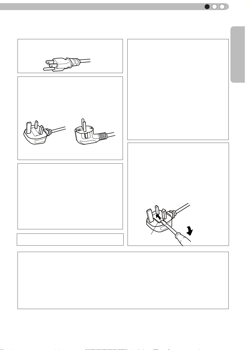
For USA and Canada only
Use only the following power cord.
Power cord
The power supply voltage rating of this product is
AC110V – AC240V. Use only the power cord
designated by our dealer to ensure Safety and EMC.
Ensure that the power cable used for the projector is
the correct type for the AC outlet in your country.
Consult your product dealer.
Power cord
For United Kingdom For European continent
countries
WARNING:
Do not cut off the main plug from this
equipment.
If the plug tted is not suitable for the power points
in your home or the cable is too short to reach a
power point, then obtain an appropriate safety
approved extension lead or adapter or consult your
dealer. If nonetheless the mains plug is cut off,
dispose of the plug immediately, to avoid a possible
shock hazard by inadvertent connection to the main
supply. If a new main plug has to be tted, then
follow the instruction given below.
WARNING:
THIS APPARATUS MUST BE EARTHED.
IMPORTANT (Europe only):
The wires in the mains lead on this product are
colored Vert et jaune in accordance with the
following cord:
Green-and-yellow
Blue
Brown
As these colors may not correspond with the
colored making identifying the terminals in your
plug, proceed as follows:
The wire which is colored green-and-yellow must
be connected to the terminal which is marked M
with the letter E or the safety earth or colored
green or green-and-yellow. The wire which is
colored blue must be connected to the terminal
which is marked with the letter N or colored black.
The wire which is colored brown must be
connected to the terminal which is marked with the
letter L or colored red.
:Earth
:Neutral
:Live
POWER CONNECTION
(United Kingdom only)
HOW TO REPLACE THE FUSE:
When replacing the fuse, be sure to use only a
correctly rated approved type, re-t the fuse cover.
IF IN DOUBT —— CONSULT A COMPETENT
ELECTRICIAN.
Open the fuse compartment with the blade
screwdriver, and replace the fuse.
(* An example is shown in the illustration below.)
Fuse
Dear Customer,
This apparatus is in conformance with the valid European directives and standards regarding
electromagnetic compatibility and electrical safety.
European representative of JVC KENWOOD Corporation is:
JVC Technical Services Europe GmbH
Postfach 10 05 04
61145 Friedberg
Germany
5
Page 6
1
Getting started
ENGLISH
Information for Users on Disposal of Old Equipment and Batteries
[European Union only]
These symbols indicate that equipment with these symbols
should not be disposed of as general household waste. If you
want to dispose of the product o r battery, please consider the
collection systems or fa cilities for appr opriate recycling.
Notice: The sign Pb below the symbol for batteries indicates that
this battery contains lead.
Products
Battery
DEUTSCH
Benutzerinformationen zur Entsorgung alter Geräte und Batterien
[Nur Europäische Union]
Diese Symbole zeigen an, dass derartig gekennzeichnete Geräte
nicht als normaler Haushaltsabfall entsorgt werden dürfen. We
nden Sie sich zur Entsorgung des Produkts oder der Batterie an
die hierfür vorgesehenen Sammelstellen oder Einrichtungen,
damit eine fachgerechte Wiederverwertung möglich ist.
Hinweis: Das Zeichen Pb unterhalb des Batteriesymbols gibt an,
Produkte
dass diese Batterie Blei enthält.
Batterie
FRANÇAIS
Informations relatives à l’élimination des appareils et des piles usagés, à
l’intention des utilisateurs
[Union européenne seulement]
Si ces symboles gurent sur les produits, cela signie qu’ils ne
doivent pas être jetés comme déchets ménagers. Si vous voulez
jeter ce produit ou cette pile, veuillez considérer le système de
collection de déc hets ou les centres de recyclage appropriés.
Notication: La marque Pb en dessous du symbole des piles
indique que cette pile contient du plomb.
Produits
Pile
NEDERLANDS
Informatie voor gebruikers over het verwijderen van oude apparatuur en
batterijen
[Alleen Europese Unie]
Deze symbolen geven aan dat appara tuur met dit symbool niet
mag worden weggegooid als algemeen huishoudelijk afval. Als u
het product of de batterij wilt weggooien, kun t u inzamelsystemen
of faciliteiten voor een geschikte recycling gebruiken.
Opmerking: Het teken Pb onder het batterijsymboo l geeft aan
dat deze batterij lood bevat.
Batterij
Producten
6
Page 7
Getting Started
ENGLISH
ESPAÑOL / CASTELLANO
Información para los usuarios sobre la eliminación de baterías/pilas usadas
[Sólo Unión Europea]
Estos símbolos indican que el equipo con estos símbolos no debe
desecharse con la basura doméstica. Si desea desechar el pro
ducto o batería/pila, acuda a los sistemas o centros de recogida
para que los reciclen debidamente.
Atención: La indicación Pb debajo del símbolo de batería/pila
indica que ésta contiene plomo.
Productos
Baterías/pilas
ITALIANO
Informazioni per gli utenti sullo smaltimento delle apparecchiature e batterie
obsolete
[Solo per l’Unione Europea]
Questi simboli indicano che le apparecchiature a cui sono relativi
non devono essere smaltite tra i riuti domestici generici. Se si
desidera smaltire questo prodotto o questa batteria, prendere in
considerazione i sistem i o le strutture di raccolta appropriati per
il riciclaggio corretto.
Nota: Il simbolo Pb sotto il simbolo delle batter ie indica che
Prodotti
questa batteria contiene piombo.
Batteria
PORTUGUÊS
Informação para os utilizadores acerca da eliminação de equipamento usado e
pilhas
[Apenas União Europeia]
Estes símbolos indicam que o equipamento com estes símbolos
não deve ser eliminado juntamente com o restante lixo doméstico.
Se p retende eliminar o produto ou a pilha, utilize os sistemas de
recolha ou instalações para uma reciclagem apropriada.
Aviso: O sinal Pb abaixo do símbolo para pilhas indica que esta
pilha contém chumbo.
Produtos
Πληροφορίες για την απόρριψη παλαιού εξοπλισμού και μπαταριών
[ Ευρωπαϊκή Ένωση μόνο ]
Αυτά τα σύμβολα υποδηλώνουν ότι ο εξοπλισμός που τα φέρει
δεν θα πρέπει να απορριφθεί ως κοινό οικιακό απόρριμμα . Εάν
επιθυμείτε την απόρριψη αυτού του προϊόντος ή αυτής της
μπαταρίας , χρησιμοποιήστε το σύστημα περισυλλογής ή
εγκαταστάσεις για ανάλογη ανακύκλωση .
Σημείωση: Το σύμβολο Pb κάτω από το σύμβολο μπαταρίας
Προϊόντα
υποδηλώνει ότι η μπαταρία περιέχει μόλυβδο .
Pilha
ΕΛΛΗΝΙΚΑ
Μπαταρία
7
Page 8
1
Getting started
DANSK
Brugerinformation om bortskaffelse af gammelt udstyr og batterier
[Kun EU]
Disse symboler angiver, at udstyr med disse symboler ikke må
bortskaffes som almindeligt husholdningsaffald. Hvis du ønsker at
smide dette produkt eller batteri ud, bedes du overveje at bruge
indsamlingssystem et eller steder, hvor der kan ske korrekt gen
brug.
Bemærk: Tegnet Pb under symbolet for batterierne angiver, at
Produkter
dette batteri indeholder bly.
Batteri
SUOMI
Tietoja vanhojen laitteiden ja akkujen hävittämisestä
[Vain Euroopan unioni]
Nämä symbolit ilmaisevat, että symboleilla merk ittyä laitetta ei
tulisi hävittää tavallisen kotitalousjätteen mukana. Jos haluat hävit
tää tuotteen tai sen akun, tee se hyödyntämällä akkujen
keräyspisteitä tai muita kier rätyspaikkoja .
Huomautus: Akkusymbolin alapuolella oleva Pb-merk intä tarkoit
taa, että akku sisältää lyijyä.
Tuotteet
Akku
SVENSKA
Information för användare gällande bortskaffning av gammal utrustning och
batterier
[Endast den Europeiska unionen]
Dessa symboler indikerar att utrustning med dessa symboler inte
ska hanteras som vanligt hushållsavfall. Om du vill bortsk affa
produkten eller batteriet ska du använda uppsamlingssystem eller
inrättningar för lämplig återvinning.
Observera: Märkningen Pb under symbolen för batterier indikerar
att detta batteri innehåller bly.
Batteri
Produkter
NORSK
Opplysninger til brukere om kassering av gammelt utstyr og batterier
[Bare EU]
Disse symbolene viser at utstyr med dette symbolet, ikke skal
kastes sammen med vanlig husholdningsavfall. Hvis du vil kass
ere dette produkte t eller batteriet, skal du vurdere å bruke innsam
lingssystemene eller andre muligheter for riktig gjenbruk.
Merk: Tegnet Pb under symbolet for batterie r, viser at batteriet
Produkter
inneholder bly.
Batteri
8
Page 9
Getting Started
ENGLISH
Сведения для пользователей по утилизации старого оборудования и
батарей
[только для Европейского союза]
Данные символы указывают на то, что оборудование, на
которое они нанесены, не должны утилизироваться, как
обычные бытовые отходы. При необходимости утилизировать
такое изделие или батарею обратитесь в специальный пункт
сбора для их надлежащей переработки.
Уведомление: Надпись Pb под символом батар ей указывает
Изделия
на то, что данная батарея содержит свинец.
Батарея
Informace pro uživatele k likvid aci starého zařízení a baterií
[Pouze Evropská unie]
Tyto symboly označují, že produkty s těmito symboly se nesmí
likvidovat jako běžný odpad. Pokud chcete produkt nebo baterii
zlikvidovat, využijte sběrný systém nebo jiné zařízení, které zaji stí
řádnou recyklaci.
Upozornění: Značka Pb pod symbolem pro ba te rie znamená, že
Produkty
tato baterie obsahuje olovo.
Baterie
Informacje dla użytkowników dotyczące poz bywania się zużytego sprzętu i
baterii
[Tylko kraje Unii Europejskiej]
Te symbole oznaczają, że sprzę tu nie należy wyr zucać razem z
odpadami gospodarczymi. Jeśli trzeba po zbyć się tego produktu
lub ba terii, proszę skorzystać z systemu odbioru lub urządzeń do
zbió rki odpadów elektronicznych, w celu odpowiedniego ponowne
go ich przetworzenia.
Uwaga: Oznaczenie Pb, znajdujące się pod symbole m baterii
Produkty
wskazuje, że ta bateria zawiera ołów.
Felhasználói információ az elhasznált be rendezések és akkumulátorok
elhelyezéséről
[Csak az Európai Unióban]
Ez a szimbólum azt jelzi, hogy a berendezés nem helyezhető az
általános háztartási hulladék közé. Ha meg szeretne szabadulni a
terméktől vagy az akkumulátortól, akkor legyen tekintettel az
gyűjtő rendszerre vagy intézményekre a megfelelő hasznosítás
érdekében.
Megjegyzés: Az alábbi Pb szimbólum - ha az akkum ulátoron
Termékek
megtalálható - azt jelzi, hogy az akkumulátor ólmot
tartalmaz.
POLSKI
Bateria
MAGYAR
Akkumulátor
9
Page 10
1
Getting started
Cрпска
Informacije za korisnike o odlaganju stare opreme i baterija
[Samo u zemljama gde se primenjuje]
Ovi simboli ukazuju da proizvod i baterije sa ovim simbolom ne
smeju biti odloženi kao nesortiran kućni otpad. Ako želite da ih se
rešite, molimo vas da ne upotrebljavate običnu kantu za đubre.
Postoje zasebni sistemi za prikupljanje ovakvih proizvoda.
Naznaka: Hemijski simbol Pb ispod simbola za baterije
ukazuje na to da li baterija sadrži olovo.
Baterija
Produkt
10
Page 11

Getting Started
ENGLISH
70
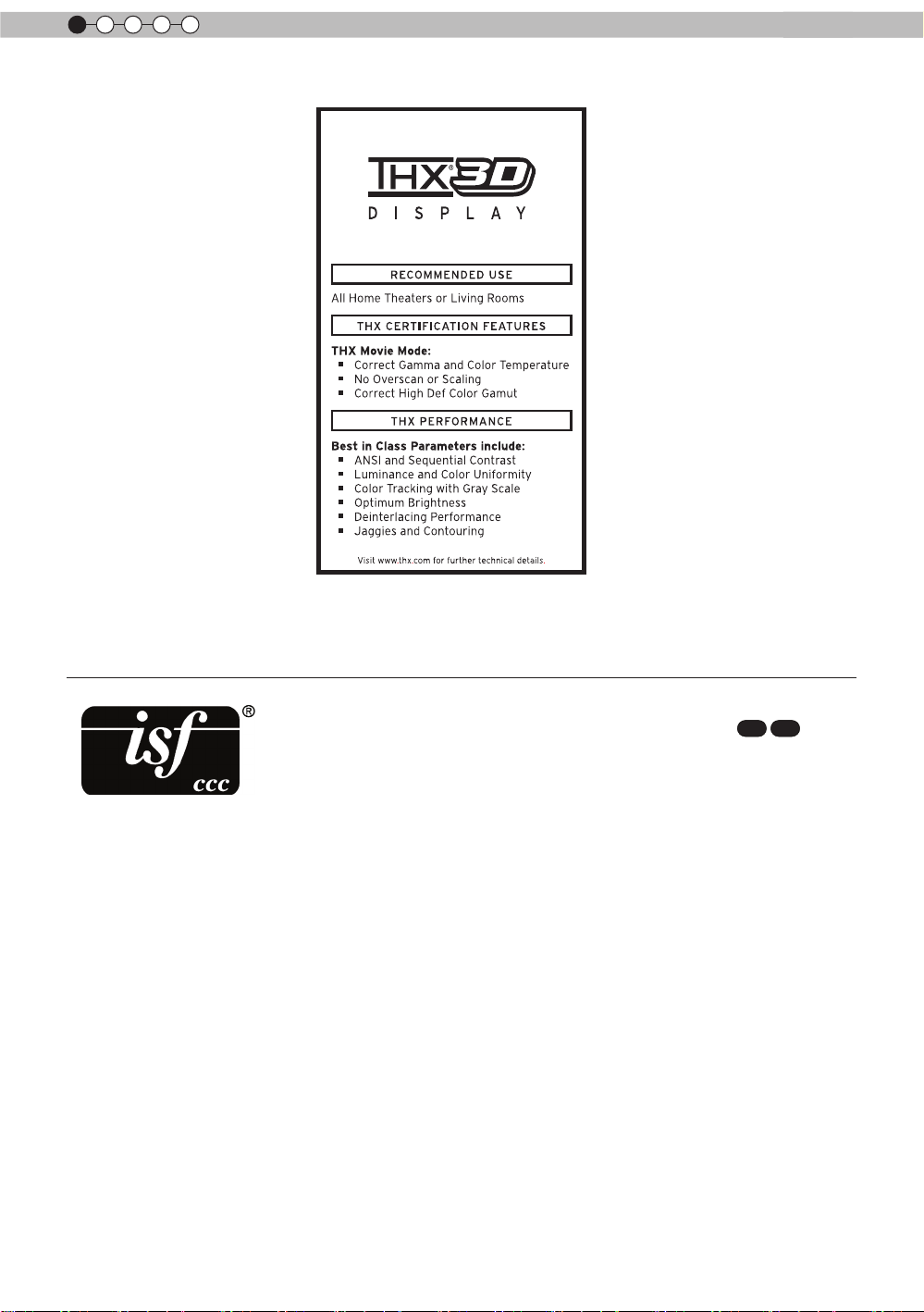
THX Certication
THX Certication
Established by lm producer George Lucas, THX aims to enhance the reproduction of
audio sound and video images intended by lmmakers by setting quality standards for
cinema viewing environments as well as home entertainment systems.
Based on the know-how that we have cultivated over the past 25 years in areas including
lm production, cinema viewing environment design, and audio/video editing, we have
established a partnership with JVC KENWOOD Corporation to develop an unprecedented home theater projector system.
The emphases of THX Certication lie in the video quality and signal processing
capability of projector products. JVC projectors, DLA-X90R and DLA-X70R, are equipped
with the THX mode, which is able to bring out the full potential of the projector when playing movies on a large screen.
90
Received “THX 3D Display Certication” (*1) specied by THX Ltd.
In addition, the certication standards were established with the aim to “faithfully
reproduce images at home according to the intentions of the lm director” during
playback of 2D or 3D images, and they are “a proof of high denition and high image
quality”, indicating that a certied product has cleared more than 400 rigorous image
quality tests including accuracy of color reproduction, cross-talk, viewing angles, and
video processing performance.
CAUTION
In order for you to enjoy 3D movies:
• Please get ready “3D glasses” and a “3D Sync Emitter” (both sold separately).
• Please read through “Safety Precautions” (Reference page: 4), and the precautions in
“Explanatory Notes on the 3D System” in “Operation Guide (Glossary)”
(Reference page: 75 to 77).
*1: The recommended screen size is 90″ (16:9), and this is limited to front
projection only.
11
Page 12
1
Getting started
For detail information about ISF, please refer web site
http://www.imagingscience.com/
90
70
12
Page 13
Getting Started
Contents
7
ENGLISH
Getting started
Safety Precautions ...........................2
70
THX Certication
90
.................11
Contents .........................................13
Accessories/Optional
Accessories ....................................14
Check the Accessories .............................. 14
Optional Accessories ................................. 14
Controls and features ....................15
Main body - Front ......................................15
Main body - Bottom ...................................15
Main body - Rear ....................................... 16
Main body - About the indicator display .....17
Main body - Warning display and
conrmation/response ...............................18
Main body - Input terminal ......................... 19
How to insert batteries into the remote
control ........................................................ 21
Preparation
About installation ...........................22
IImportant points concerning the
installation .................................................22
Installing the Projector and Screen ...........23
Set Angle ................................................ 23
Shift .......................................................23
Fixation of the projector ............................. 24
Screen Size and Projection Distance ........25
Effective Range of Remote Control Unit....25
About the connection .....................26
Types of possible input signals
(PC compatible) ......................................... 27
Connection to the unit ...............................28
Connection of the power cord (provided)
..................................................................34
Masking the Surrounding Area of
an Image ................................................40
Temporary turning-off of the video ..........41
Adjustment of the keystone correction ...41
Adjustments and settings
in the menu .....................................42
Structure of the menu hierarchy
(summary) .................................................42
Menu operation button ..............................50
Menu operation procedure ........................51
Menu item description ...............................52
Operation guide (glossary) ............74
Maintenance
Replacing the Lamp .......................78
Lamp replacement procedure ...................78
Resetting lamp Time ..................................80
Method for cleaning and
replacing lters ...............................82
Others
Troubleshooting .............................84
In case this message is
displayed .........................................86
RS-232C Interface ...........................87
RS-232C Specications ............................87
TCP/IP-connection ....................................87
Command Format .....................................88
RS-232C Communication Examples ......... 90
Copyright and Caution ...................91
About Trademarks and Copyright ..............91
Caution ......................................................91
Specications .................................92
Dimensions ................................................ 94
Index ................................................95
Operation
Basic Operation ..............................36
Basic operation procedures ....................... 36
Frequently used useful functions ............... 38
Setting the Screen Size .......................... 38
CAUTION
About the marks used in this
book
Compatible only with DLA-X90R
90
Compatible only with DLA-X70R
70
Compatible only with DLA-X30
X
30
13
Page 14

1
Getting started
Accessories/Optional Accessories
Check the Accessories
Lens Cover 30 ..........................................................................1 piece
Remote Control
AAA size Batteries (for operation conrm)..................................2 pieces
Power Cord For the US market (2 m)
Power Cord For the EU market (2 m) .........................................1 piece
Power Cord For the UK market (2 m) .........................................1 piece
●
Instruction manual (this book), warranty card and other printed material are also included.
..........................................................................1 piece
.........................................1 piece
Optional Accessories
Please check with your authorized dealer for details.
●
Replacement Lamp: PK-L2210U
●
Replacement Filter: PC010661199
●
3D-Glasses: PK-AG1-B , PK-AG2-B
●
3D Synchro Emitter: PK-EM1
14
Page 15
Getting Started
Controls and features
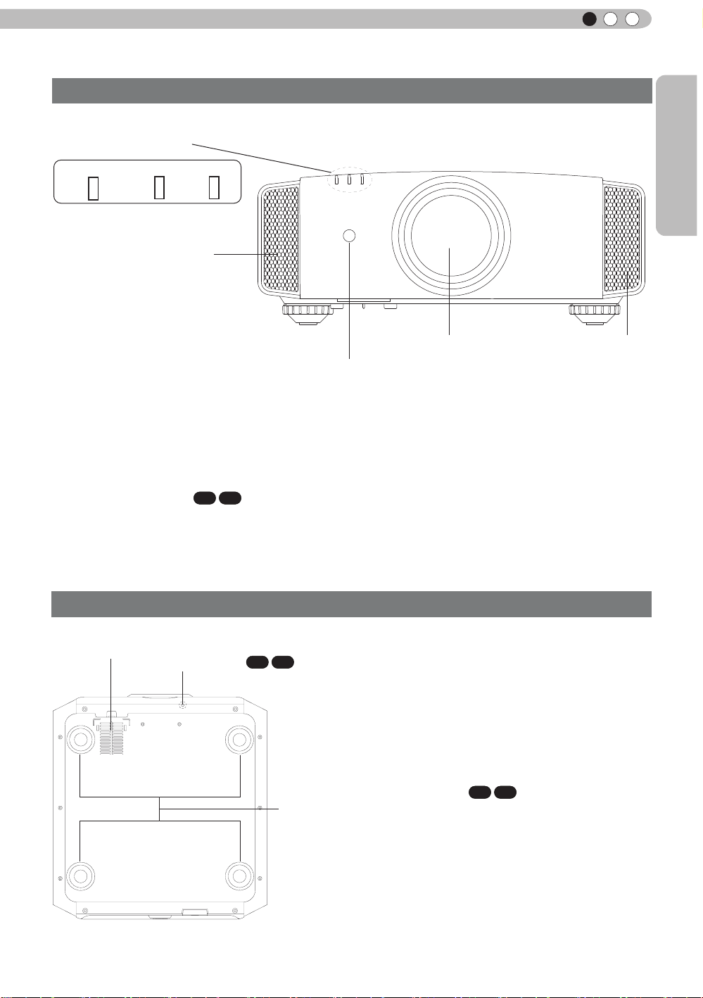
Main body - Front
③ Indicator
STANDBY/ON LAMP WARNING
ENGLISH
④ Exhaust Ve
nt
② Remote receiver (front)
① Lens
This is a projection lens. Please do not look
inside during projection.
Lens cover
The lens cover opens/closes when the power
supply is turned on/off.
(Reference page: 66)
90
70
② Remote receiver (front)
Please aim the remote control at this area when
using it.
(*) There is also a remote receiver at the rear.
Main body - Bottom
⑤ Inlets
⑥ Manual button for
70
lens cover
90
① Lens
Lens cover
④ Exhaust
Vent
③ Indicator
Please see “About the indicator display” for
details. (Reference page: 17)
④ Exhaust Vent
Warm air flows out in order to cool the interior of
the set. Please do not block the vents.
⑤ Inlets (at 3 points on the rear/
bottom)
In order to cool the inside of the unit, air is let
inside. Do not block or prevent the outflow of
hot air. Doing so could lead to failure of the unit.
(*) There are inlets at two points on the right
and left sides of the rear side.
(Reference page: 16)
⑦ Feet
⑥ Manual operation button of the
70
lens cover
The lens cover can be opened when pressed
down.It is used for maintenance and not used
during normal use.
90
⑦ Feet
The height (0 to 5 mm) can be adjusted by
turning the foot.
When the foot is removed, it can be used as the
mounting holes for the ceiling mount bracket.
(Reference page: 24)
15
Page 16
1
Getting started
Controls and features (continued)
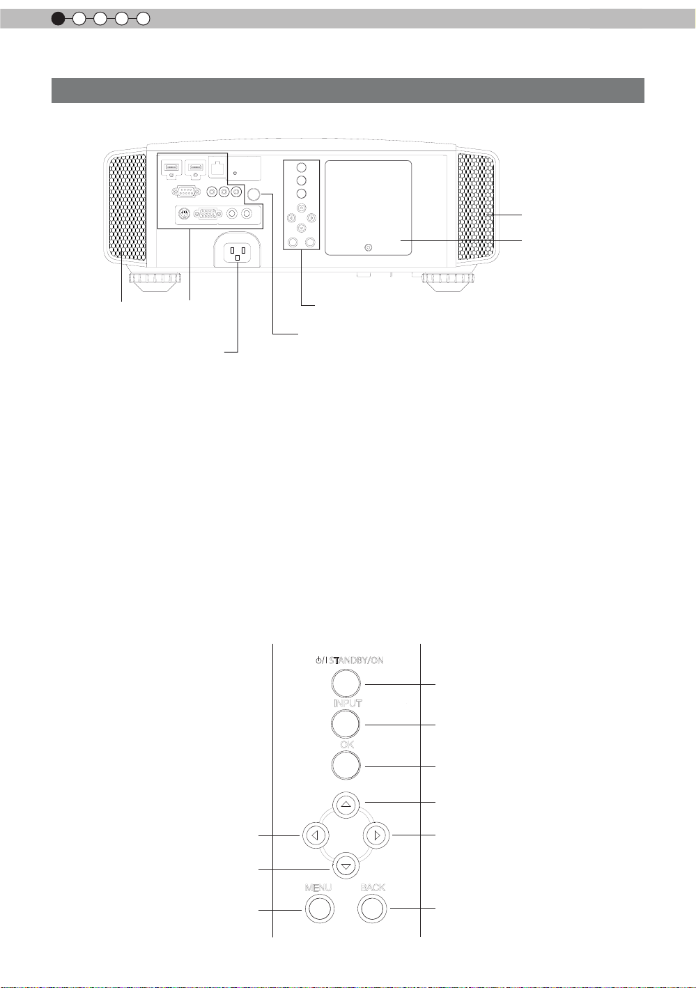
Main body - Rear
⑤ Inlets
⑨ Lamp Cover
⑤ Inlets
⑧ I
nput
terminal
⑫ Power input
terminal
⑧ Input terminal
There is also a terminal other than the input
terminal for video images, such as those used
for controlling or optional equipment. Please see
“
bout input terminals” for detailed information
A
about terminals. (Reference page: 19)
⑨ Lamp Cover
When replacing the light source lamp, remove
this cover. (Reference page: 78)
⑩ Operation panel
See the following illustration “Control panel” for
more details.
O
peration panel
■
⑩ Operation panel
⑪ L
ight receiving section
of the remote control (rear)
⑪ Light receiving section of the
remote control (rear)
Please aim the remote control at this section
when using.
(*) There is also a light receiving section at
the rear.
⑫ Power input terminal
This is the power input terminal. It is
connected via the supplied power cord.
(Reference page: 34)
STANDBY/ON
To
turn on/off the power
INPUT
switch input
To
OK
To select or conrm
16
Left button
Down button
To
display the menu
MENU
BACK
Up button
Right button
return to the previous menu
To
Page 17
Getting Started
ENGLISH
Controls and features (continued)
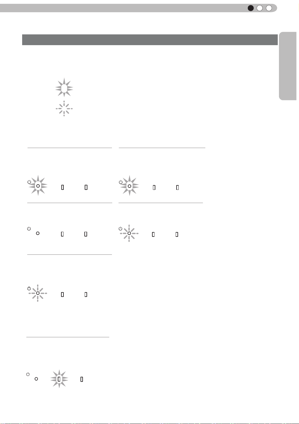
Main body - About the indicator display
Warnings and indications used during normal operation mode of this unit are displayed with the indicators
for [STAND BY / ON], [LAMP], [WARNING] at the front of this unit.
Meaning of the lighting gures:
The display the indicator lights.
They display flashing of the indicator.
Operation mode display
Displays the color and lighting/flashing of the [STAND BY / ON] indicator.
STAND BY
Duringstandby
STANDBY/ON
All Off
Duringimageprojection
STANDBY/ON
STAND BY
Duringcooldown
STANDBY/ON
Light on(Red)
LAMP WARNING
LAMP WARNING
Blinking(Red)
LAMP WARNING
STAND BY
Whileactivatingthelamp
(about1minute)
STANDBY/ON
STAND BY
When"Hide"issettoON
STANDBY/ON
Light on(Green)
LAMP WARNING
Blinking(Green)
LAMP WARNING
Criterion indication of the lamp replacement
Displays lighting/flashing of the [LAMP] indicator. Moreover, the [STAND BY / ON] indicator, which shows
the operation mode of this unit, is displayed as described above. (Reference page: 92)
LAMP Light on(orange)
Lamp replacement is
near(When accumulated lamp
time has exceeded 2900 hours)
STANDBY/ON
LAMP WARNING
17
Page 18
1
Getting started
Controls and features (continued)
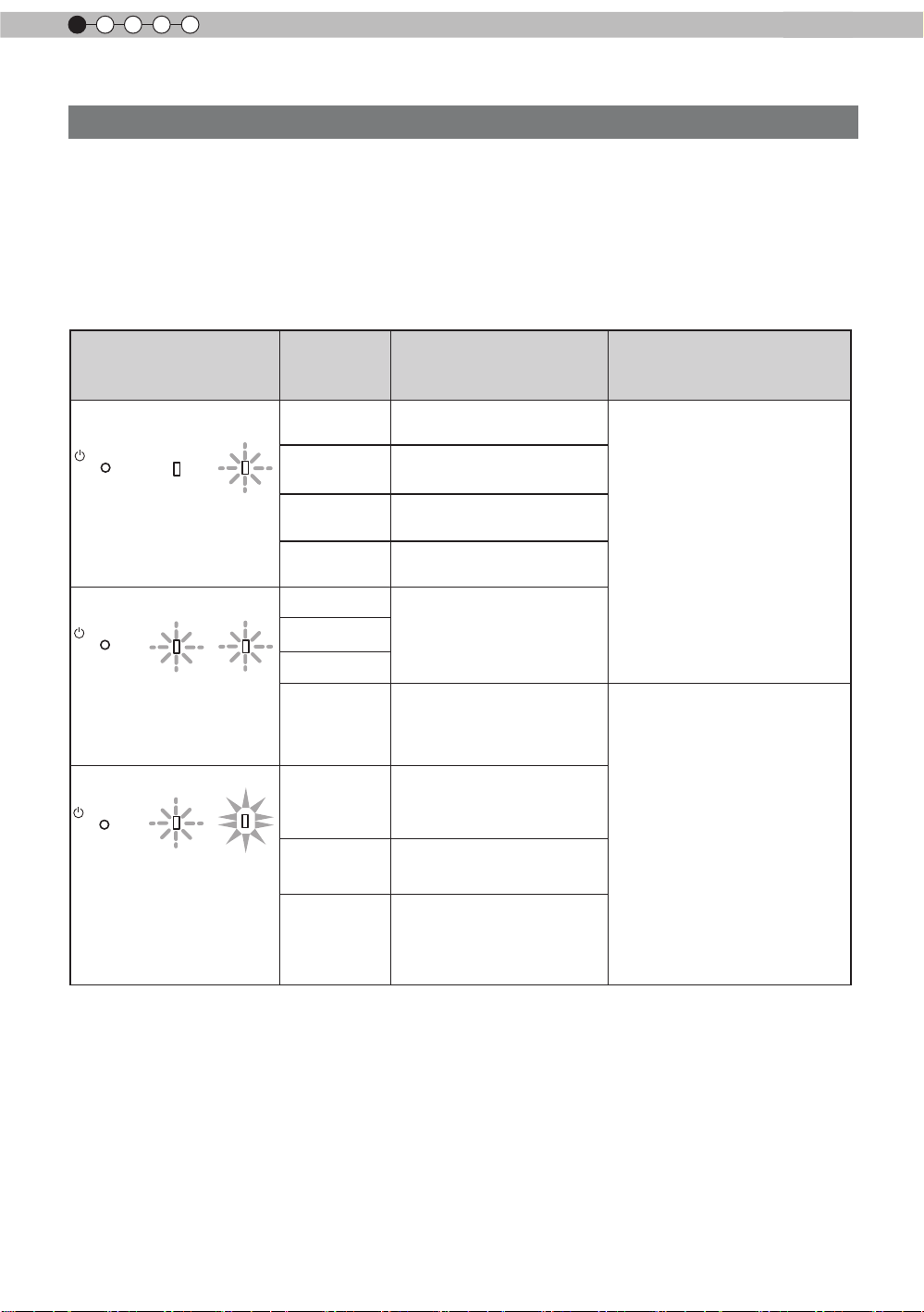
Main body - Warning display and confirmation/response
Warning display
Yo
u are informed of the contents of warning notices by the (repeated) displays of the [WARNING] and
[LAMP] indicators. Moreover,
is displayed simultaneously as described above.
Upon activation of the warning mode, the projection is interrupted at the same time for about 60 seconds
and the cooling fan is turned on. Please disconnect the power plug from the electric socket after the
cooling fan has stopped. Subsequently,
countermeasures.
the [STAND BY / ON] indicator, which shows the operating mode of the unit,
please perform the following checks and take appropriate
Lighting/flashing lights
status diagram
STANDBY/ON
LAMP WARNING
red
(
) (
red
red
)
)
Mode
display
STANDBY/ON
Mode
display
STANDBY/ON
Mode
display
(*)
LAMP WARNING
orange
(
Simultaneous
flashing
LAMP WARNING
orange
(
) (
Blinking
Frequency
1 times
Abnormalities in the power
supply
2 times Cooling fan stops
3 times
4 times
Internal temperature is too
high
External temperature is
too high
1 times
2 times
3 times
)
4 times
Abnormal electrical circuit
If something is wrong with
the automatic lens cover
Lamp does not light up
1 times
and unit is unable to
project
2 times
Lamp is turned off
projection
Content
during
Confirmation and
countermeasures
●
Check that nothing is
blocking the air inlets.
●
Check that the external
temperature is normal.
Action
Leave the unit until it cools
down.
After that, turn on the power
again.
●
Check that an impact shock
has not occurred during
operation.
●
Check that the lamp
unit and lamp cover are
correctly installed.
●
Check that nothing is
blocking the auto lens
cover.
3 times
If the warning indication is displayed again, please wait for the cooling fan stopped, then pull out the power
plug from the power outlet. T
hen call your authorized dealer for repair.
(*) If the scheduled time for the replacement of the lamp is exceeded, the light might light up.
Lamp cover is removed
Turn on the power again.
18
Action
Page 19
Getting Started
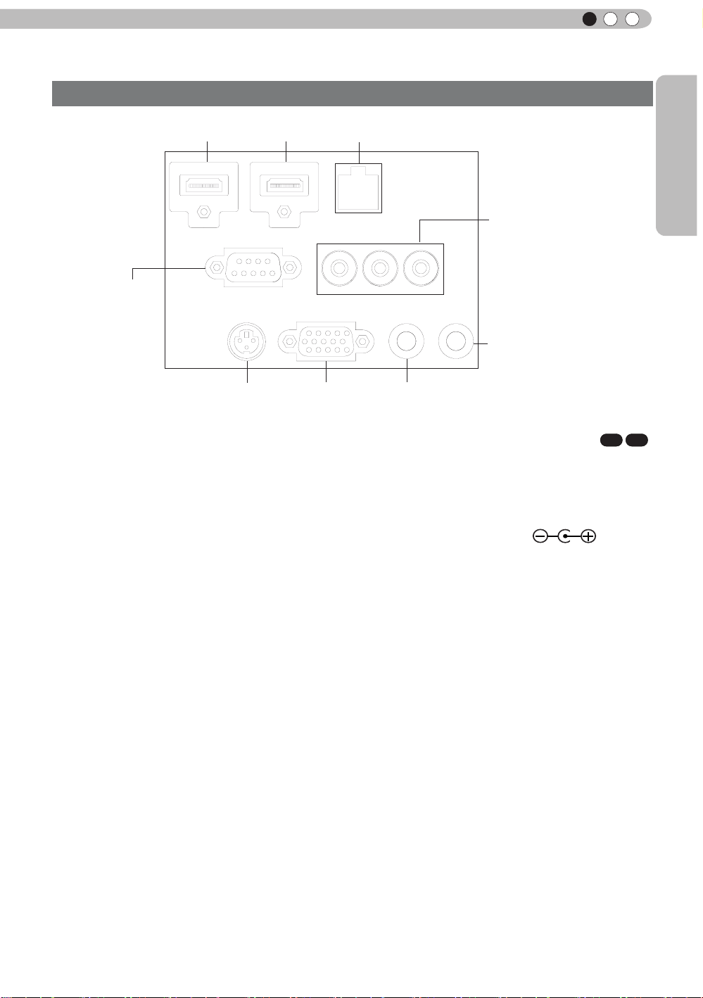
Controls and features (continued)
Main body - Input terminal
① HDMI 1 ② HDMI 2 ③ LAN
⑤ COMPONENT
④ RS-232C
⑨ REMOTE
ENGLISH
⑥ 3D SYNCHRO
① HDMI 1 Terminal
② HDMI 2 Terminal
You can connect a device equipped with HDMI
output, etc. It is tted to the M3 lock hole.
Screw hole depth 3mm. (Reference page: 29)
③ LAN terminal “RJ-45”
This is a LAN-terminal. If one connects an
external PC, it is possible to control this unit by
sending control commands.
(Reference page: 33)
④ RS-232C terminal (male D-Sub 9
pin)
This is a RS-232C interface standard terminal.
If one connects an external PC, it is possible to
control this unit. (Reference page: 32)
⑤ COMPONENT terminal “RCAx3”
It is also used as input terminal for analog
RGB (G on Sync) signals, component (Y, Cb,
Cr) signals, DTV format (Y, Pb, Pr) signals. It
can also be connected with devices, which are
equipped with signal output, etc. (Reference
page: 30)
⑥ 3D SYNCHRO terminal
3D synchro emitter: it is connected to the PKEM1 (sold separately) when enjoying 3D video
contents. (Reference page: 31)
⑦ PC
⑧ TRIGGER
⑦ PC terminal “D-Sub 15 pin”
This is an input term used for Personal Computer
(PC) signals only (RGB video signals and sync
signals). Use to connect a computer display
output terminal, etc. (Reference page: 31)
⑧ TRIGGER terminal( )
DC power supply output terminal with DC12V,
100mA. It is used for output signals which control
the vacillating screen responding to the SCREEN
TRIGGER. Please note it can cause damage
to your equipment if the connection is done
incorrectly. (Tip = DC +12 V, Sleeve = GND)
(Reference Page: 32, 72)
⑨ REMOTE terminal to “Stereo mini
jack”
In case it is impossible to use the remote control
due to the installation of this unit’s dedicated
BOX or rear projection, one can set up an
external light receiving section. It is used to
connect this external receiver and this unit. There
is no such product as an external light receptor.
Therefore, please consult your authorized JVC
KENWOOD Corporation. (Reference page: 33)
90
70
19
Page 20
1
Getting started
Controls and features (continued)
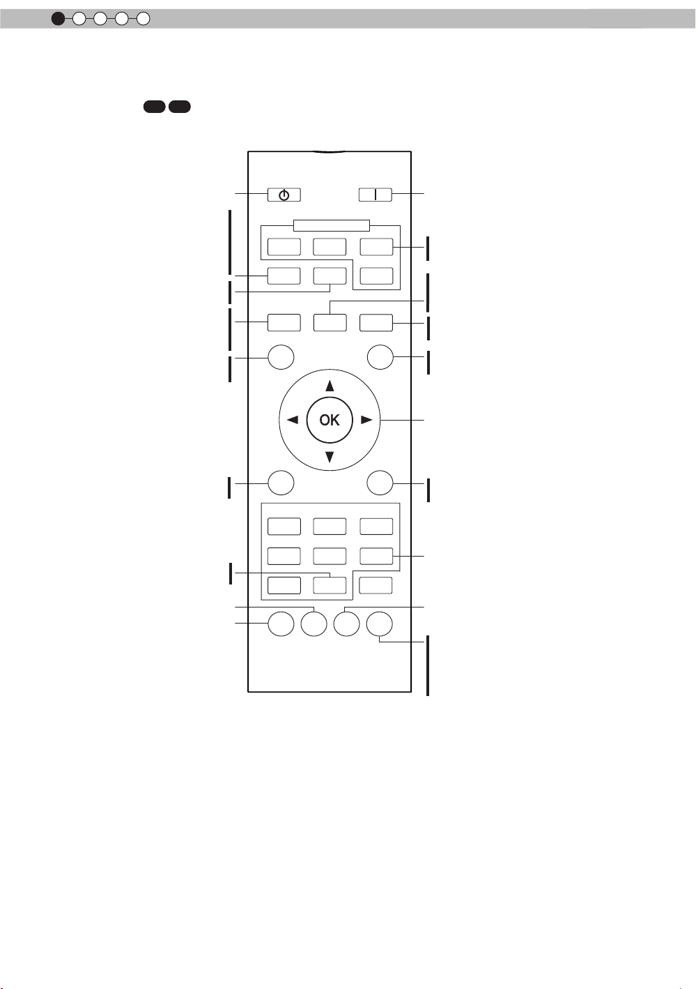
■
Remote Control
70
90
90
INPUT
HDMI 2
3D
SETTING
LENS
MEMORY
ON
COMP
PC
ANAMO.
LIGHT
To turn on the power
select input mode
To
.
(Reference page: 36)
This sequentially switches the call up/
save/edit modes of your lens memory
(Reference page: 65)
This sequentially switches anamorphic
modes.(Reference page: 64)
illuminate buttons on the remote
To
control for 7 second
select or confirm
To
turn off the power
To
This button sequentially
switches 3D formats
(Reference page: 63)
his function cannot be used
(*) T
when inputting 2D and frame
packing 3D signals
Display the 3D setting
menu(Reference page: 63)
Use this function to sequentially
select focus, zoom and shift
adjustment lens controls.
(Reference page: 65)
hide the image temporarily
To
(Reference page: 41)
STAND BY
HDMI 1
3D
FORMAT
LENS.
CONTROL
HIDE
display/close the menu
To
(Reference page: 50)
This sequentially switches
between users 1-5
To
adjust color temperature
set gamma
To
MENU
FILM
NATURAL
THX
GAMMA
PICTURE MODE
CINEMA
STAGE 3D
USER
COLOR
COLOR
TEMP
P.FILE
BACK
ANIME
C.M.D.
PIC.
ADJ.
return to the previous menu
To
(Reference page: 50)
To
switch picture mode
Color Profile
Sequentially switched picture
adjust items, such as contrast and
brightness.The switching items are
not the same for diff
erent models, or
different picture modes.
20
Page 21

Getting Started
Controls and features (continued)
BACK
HIDE
LIGHT
LENS
MEMORY
LENS AP.
HDMI 1
STAND BY
3D
FORMAT
HDMI 2
COMP
.
LENS.
CONTROL
MENU
GAMMA
SPACE
COLOR
ADJ.
PIC.
ON
FILM
NATURAL
STAGE 3D
USER
INFO
C.M.D.
ANIME
CINEMA
PICTURE MODE
INPUT
TEMP
COLOR
ANAMO.
3D
SETTING
7
■
Remote Control
X
30
X
ENGLISH
turn off the power
To
This button sequentially switches
3D formats (Reference page: 63)
his function cannot be used
(*) T
when inputting 2D and frame
packing 3D signals
Display the 3D setting menu
(Reference page: 63)
Use this function to sequentially
select focus, zoom and shift
adjustment lens controls.
(Reference page: 65)
hide the image temporarily
To
(Reference page: 41)
To display/close the menu
(Reference page: 50)
This sequentially switches
between users 1-5.
To adjust color temperature
To set gamma
To turn on the power
To select input mode
(Reference page: 36)
This sequentially switches anamorphic
modes. (Reference page: 64)
This sequentially switches the call up/
save/edit modes of your lens memory
(Reference page: 65)
To adjust Lens Aperture
(Reference page: 57)
illuminate buttons on the remote
To
control for 7 second
To
select or confirm
return to the previous menu
To
(Reference page: 50)
switch picture mode
To
Display the information menu
(Reference page: 73)
Color Space
Sequentially switched picture
adjust items, such as contrast and
brightness.The switching items are
not the same for diff
erent models, or
different picture modes.
How to insert batteries into the remote control
①
●
If the remote control has to be brought closer to the projector to operate, it means that the batteries are
wearing out.
When this happens, replace the batteries. Insert the batteries according to the
●
Be sure to insert the end first.
●
If an error occurs when using the remote control, remove the batteries and wait for 5 minutes. Load the
batteries again and operate the remote control.
②
③
marks.
21
Page 22
2
CAUTION
CAUTION
CAUTION
Preparation
About installation
Important points concerning the installation
Please read the following carefully before the installation of this unit.
Installation environment
This unit is a precision device. Therefore, please refrain
from installation or use in the following locations.
Otherwise, it may cause re or malfunction.
• Dust, wet and humid locations.
• Sooty or cigarette smoke lled locations.
• On top of a carpet or bedding, or other soft surfaces.
• Locations with high temperatures - as located in direct
sunlight.
• Locations with high or low temperatures.
Permissible operating temperature range: +5 º to +35º .
Relative humidity range permissible for operating: 20%
~ 80% (non-condensing) .
Storage temperature tolerance: -10º to +60º.
• If the installation of the unit is done in a room with soot
and/or smoke over a longer period, even small amounts
of these substances will affect the device.This unit
cools its optical components, which produce a great
amount of heat, by sucking in air. If the optical circuits
get dirty, this might lead to malfunctions, like the video
images becoming darker or a deterioration of the color
development. Dirt sticking to the optical components
cannot be removed.
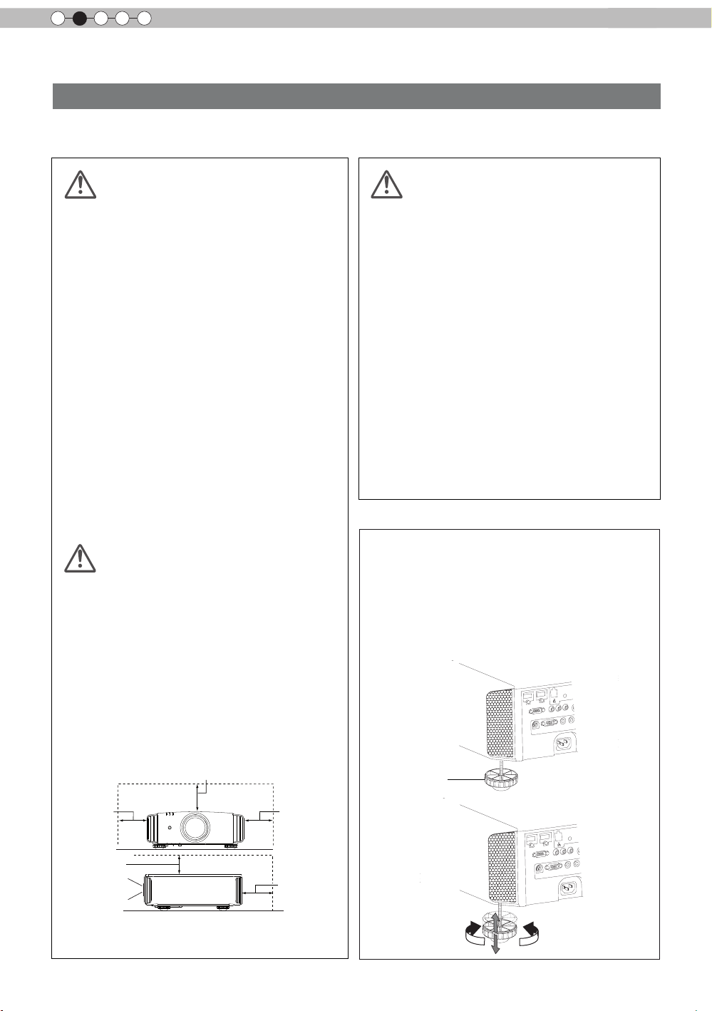
Please be careful to perform
the installation at a certain
distance from walls and
other devices
For better heat dissipation, please keep a minimum
distance between this unit and its surroundings as shown
in the following illustration.
Moreover, please open the front of the unit. If there are
any objects in front of the exhaust port, the hot air will
ow back to the unit and heat it. The hot air owing out of
the unit might cause shadows on the screen (heat haze
phenomenon).
Moreover, when it is enclosed in a space as shown in the
following illustration, please make sure that the enclosed
interior has the same temperature as the outside. High
temperatures might lead to failure of the unit.
Please be careful when using
This unit uses a projection lamp, which will get hot when
in use. Please refrain from projecting in the following
circumstances.
Otherwise, it might cause re or malfunction.
• Projection while lying on its side.
Please avoid projection if the installation of the unit is
done at an excessive angle of more than ± 30 °. It may
cause harm to the life of the lamp and color shading.
• Please avoid projection at a location where the air vents
or exhaust ports might get blocked.
Please choose a non-uniform cloth material for the screen.
If you choose something uniform, like something with a
checkered pattern, there might be interference with the
pixel array of the D-ILA components. One way to reduce
the interference pattern is to change the size of the screen,
so that it will not be so noticeable.
Inclination adjustment
for this unit
How to adjust the vertical angle
Height and inclination of the unit (0 ~ 5mm) can be
adjusted by rotating its feet. Lift the unit and adjust
the four feet.
22
300 mm
and above
150 mm
and above
Front
150 mm and above
300 mm
and above
200 mm
and above
Stand
Extend Contract
Page 23
ENGLISH
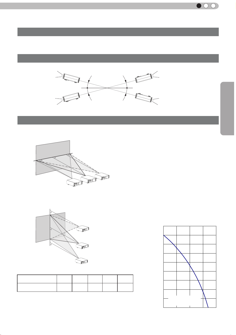
Horizontal lens shift
About installation (Continued)
Installing the Projector and Screen
While installing, please place this unit and the screen perpendicular to each other. Failing
to do so may increase trapezoidal distortion. (Reference page: 36, 52)
Set Angle
The angle range which can be set for this unit is ±30°.
30°
30°
30°
30°
●
Malfunctions may occur if the angle is not set within the above-mentioned range.
Shift
Preparation
■
Left/Right position
0% up/down position (center)
(*)
Approximately 34% (maximum) of the projected image
■
Up/Down position
0% left/right position (center)
(*)
Approximately 34% (maximum) of the projected image
Approximately 80%
(maximum) of the projected
image
Approximately 80%
(maximum) of the
projected image
Lens shift correlation chart:
Left-Right Shift(%)
Up-Down Shift(%)
●
Maximum Up-Down shift varies with the amount of Left-Right shift.
Likewise, maximum Left-Right shift varies with the amount of UpDown shift.
●
The values on the chart are intended to act as a guide. Use them
for reference during installation.
0% 10% 20% 30% 34%
80% 66% 47% 18% 0%
■
Lens shift movement
range
90
80
70
60
Vertical lens shift(%)
50
40
30
20
Lens movability
10
0 10 20
range
30 40
(%)
23
Page 24

2
Preparation
About installation (Continued)
Fixation of the projector
Measures to prevent the unit from toppling or dropping should be taken for safety reasons and
accident prevention during emergencies including earthquakes.
When mounting this unit on a pedestal or ceiling, remove the 4 feet on the bottom surface and
use all the 4 screw holes (M5 screws) to mount.
Ceiling
Precautions for Mounting
●
Special expertise and techniques are required for
mounting this unit. Be sure to ask your dealer or a
specialist to perform mounting.
●
Depth of the screw holes (screw length) is 23
mm. Use screws shorter than 23 mm but longer
than 13 mm.
Using other screws will result in
malfunctioning or cause the unit to drop.
●
When mounting to a pedestal, ensure
sufcient space (foot height of 10 mm or
higher) around the unit so that the air inlets
are not blocked.
●
Do not tilt this unit more than ±5 degrees
from side to side when using.
■
Bottom Surface
4 locations
Air inlets
●
Regardless whether the unit is still under
guarantee, JVC is not liable for any product
damage caused by mounting the unit with non-
JVC ceiling ttings or when the environment is
not suitable for ceiling-mount.
●
When using the unit hanging from a ceiling,
pay attention to the surrounding temperature.
When a heater is in use, temperature around
the ceiling is higher than expected.
24
Page 25
ENGLISH
30°
30°
20°
20°
About installation (Continued)
Screen Size and Projection Distance
Determine the distance from the lens to the screen to achieve your desired screen size.
This unit uses a 2.0x power zoom lens for projection.
■
Relationship Between Projection Screen Size and Projection Distance
Projection Screen Size
(Height, Width)
Aspect Ratio 16:9
"
60
Approx.
(
(Approx.0.9, 1.5m)
(Approx.1.0, 1.8m)
(Approx.1.1, 2.0m)
(Approx.1.2, 2.2m)
(Approx.1.4, 2.4m)
(Approx.1.5, 2.7m)
(Approx.1.6, 2.9m)
0.7, 1.3m)
70"
80"
90"
100"
110"
120"
130"
Approximate Projection
DistanceW(Wide) to T(Tele)
Approx.1.78m to
Approx.3.66m
Approx.2.09m to
Approx.4.28m
Approx.2.40m to
Approx.4.89m
Approx.2.70m to
Approx.5.51m
Approx.3.01m to
Approx.6.13m
Approx.3.31m to
Approx.6.75m
Approx.3.62m to
Approx.7.36m
Approx.3.92m to
Approx.7.98m
Projection Screen Size
(Height, Width)
Aspect Ratio 16:9
140"
(Approx.1.7, 3.1m)
150"
(Approx.1.9, 3.3m)
160"
(Approx.2.0, 3.5m)
170"
(Approx.2.1, 3.8m)
180"
(Approx.2.2, 4.0m)
190"
(Approx.2.4, 4.2m)
200"
(Approx.2.5, 4.4m)
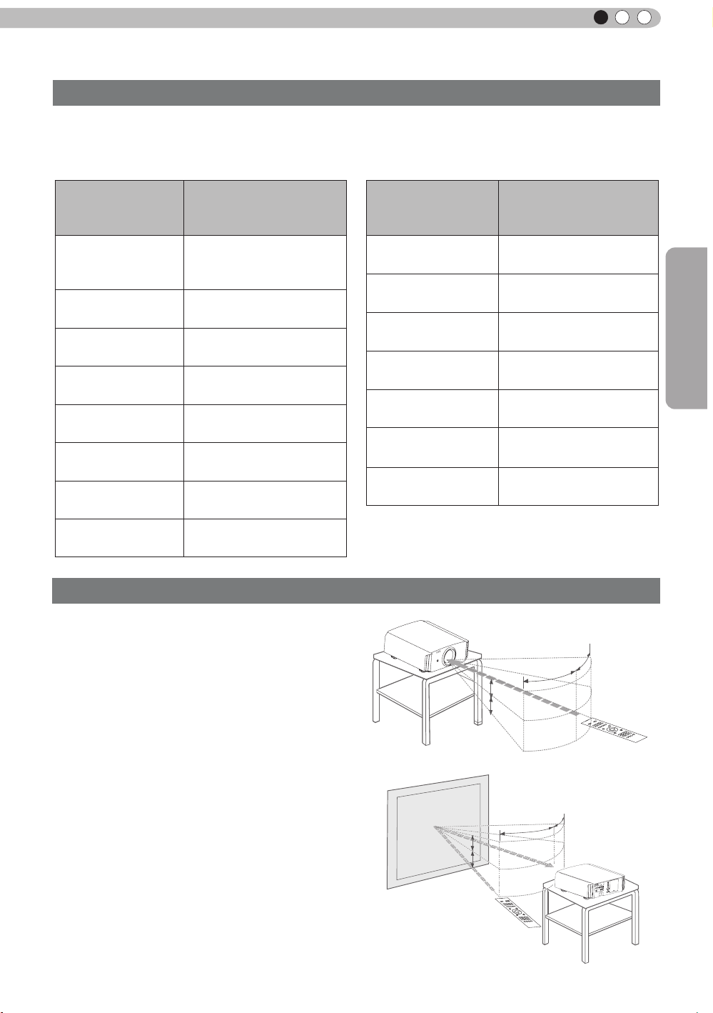
Effective Range of Remote Control Unit
Approximate Projection
DistanceW(Wide) to T(Tele)
Approx.4.23 m to
Approx.8.60m
Approx.4.53m to
Approx.9.22m
Approx.4.84m to
Approx.9.84m
Approx.5.14m to
Approx.10.45m
Approx.5.45m to
Approx.11.07m
Approx.5.75m to
Approx.11.68m
Approx.6.06m to
Approx.12.30m
Preparation
When directing the remote control toward this
■
unit.
●
When aiming the remote control towards the
remote sensor on this unit, ensure that the
distance to the sensor in front or at the rear of
this unit is within 7 m.
●
If the remote control fails to work properly, move
closer to this unit.
When reecting off a screen
■
●
Ensure that the total of distance A between this
unit and screen and distance B between remote
control and screen is within 7 m.
●
As the efciency of signals reected from the
remote control unit differ with the type of screen
used, operable distance may decrease.
Screen
This unit
20°
A
20°
B
Remote control
30°
Remote control
30°
This unit
25
Page 26
2
Preparation
About the connection
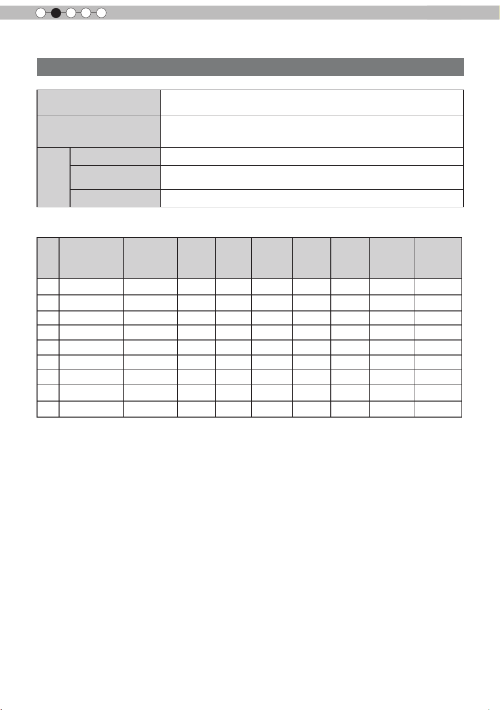
Types of possible input signals
Analog Video Input Format
signals
Digital Video Input Format
signals
frame pack method
3D
signal
●
PC signal (HDMI)
No.
side by side method
top and down method
Designation
1
2
3
4
5
6
7
8
9
WSXGA
60 640 X 480 31.500 60.000 25.200 800 525 640 480
VGA
59.94 640 X 480 31.469 59.940 25.175 800 525 640 480
VGA
SVGA
60
XGA
WXGA
+60 1440 X 900 55.919 59.999 106.470 1,904 932 1,440 900
WXGA
SXGA
WUXGA
Resolution
60 800 X 600 37.879 60.317 40.000 1,056 628 800 600
1024 X 768 48.363
60
1280 X 768 47.760
60 1280 X 1024 63.981 60.020 108.000 1,688 1,066 1,280 1,024
+60 1680 X 1050 65.222 60.002 147.140 2,256 1,087 1,680 1,050
60 1920 X 1200 74.038 59.95 154.000 2,080 1,235 1,920 1,200
480i, 480p, 576i, 576p, 720p/50Hz, 720p/60Hz,
1080i/50Hz, 1080i/60Hz
480i, 480p, 576i, 576p, 720p/50Hz, 720p/60Hz,
1080i/50Hz, 1080i/60Hz,1080p/24Hz,
1080p/50Hz, 1080p/60Hz
720p/50Hz, 720p/60Hz, 1080p/24Hz, 1080i/50Hz, 1080i/60Hz
1080i/60Hz, 1080p/60Hz, 1080i/50Hz, 1080p/50Hz, 1080p/24Hz,
720p/50Hz, 720p/60Hz
720p/50Hz, 720p/60Hz, 1080p/24Hz
fh
[kHz]fv[Hz]
60.004 65.000
60.000
dot CLK
[MHz]
79.998 1,675
Total No.
of dots
[dot]
1,344
Total No.
of lines
[line]
806 1,024
796 1,280
No. of
effective
dots
[dot]
No. of
effective
lines [line]
768
768
26
Page 27
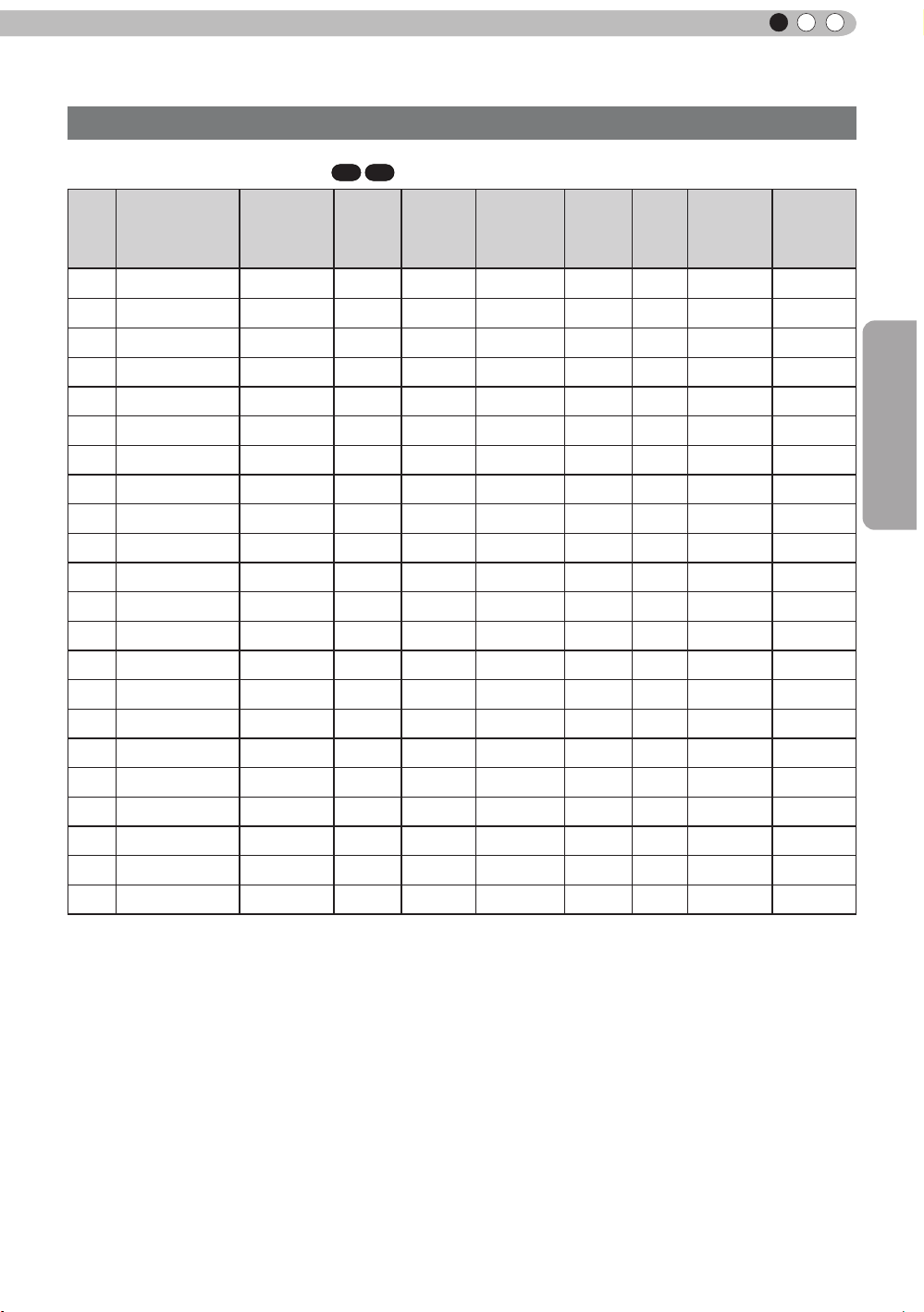
About the connection (Continued)
Types of possible input signals (PC compatible)
ENGLISH
●
PC signal (D-sub 3-lines 15 pins)
No.
Designation
1
2
3
4
5
6
7
8
9
10
11
12
13
14
15
16
17
18
WSXGA+
19 1920x1080 60 1920 X 1080 67.500 60.00 148.500 2200 1125 1920 1080
20
21
22
60 640 X 480 31.500 60.000 25.175 800 525 640 480
VGA
72 640 X 480 37.900 72.000 31.500 832 520 640 480
VGA
75 640 X 480 37.500 75.000 31.500 840 500 640 480
VGA
85 640 X 480 43.300 85.000 36.000 832 509 640 480
VGA
SVGA
SVGA
SVGA
SVGA
SVGA
60 1024 X 768 48.400 60.000 65.000 1344 806 1024 768
XGA
70 1024 X 768 56.500 70.000 75.000 1328 806 1024 768
XGA
75 1024 X 768 60.000 75.000 75.750 1312 800 1024 768
XGA
85 1024 X 768 68.700 85.000 94.500 1376 808 1024 768
XGA
WXGA
WXGA+
SXGA
SXGA+
13" 640 X 480 35.000 66.667 30.240 864 525 640 480
MAC
16" 832 X 624 49.107 75.087 55.000 1120 654 832 624
MAC
19" 1024 X 768 60.241 74.927 80.000 1328 804 1024 768
MAC
Resolution
56 800 X 600 35.200 56.000 36.000 1024 625 800 600
60 800 X 600 37.900 60.000 40.000 1056 628 800 600
72 800 X 600 48.100 72.000 50.000 1040 666 800 600
75 800 X 600 46.900 75.000 49.500 1056 625 800 600
85 800 X 600 53.700 85.000 56.250 1048 631 800 600
60 1280 X 768 47.760 60.000 79.998 1675 796 1280 768
60 1440 X 900 55.919 59.999 106.470 1904 932 1440 900
60 1280 X 1024 64.000 60.000 108.000 1688 1066 1280 1024
60 1400 X 1050 63.981 60.020 108.000 1688 1066 1400 1050
60 1680 X 1050 65.222 60.002 147.140 2256 1087 1680 1050
90
[kHz]
70
fh
fv
[Hz]
dot CLK
[MHz]
Total No.
of dots
[dot]
Total
No. of
lines
[line]
No. of
effective
dots
[dot]
effective
lines [line]
No. of
Preparation
27
Page 28
2
Preparation
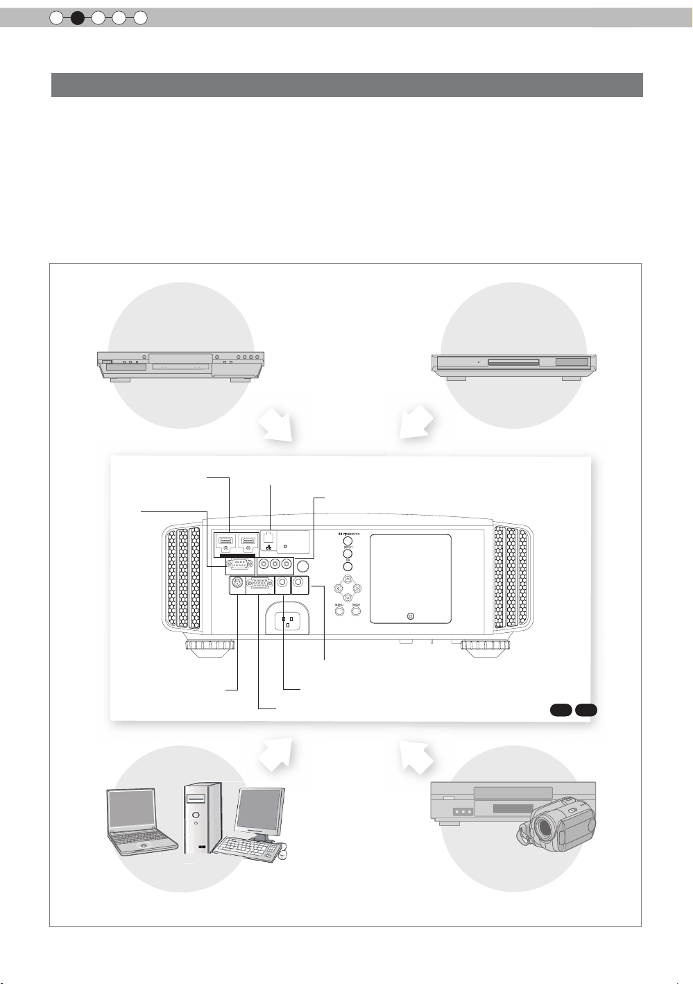
About the connection (Continued)
Connection to the unit
●
Do not turn on the power until connection is complete.
●
The connection procedures differ according to the device used. For details, refer to the instruction
manual of the device to be connected.
●
This device is used for image projection. Connect to an audio output device such as amplifier and
speaker for audio output from the connected device.
●
The images may not be displayed depending on the devices and cables to be connected.
For HDMI cable (sold separately), only use one that is HDMI-approved.
●
It may not be possible to connect to this unit depending on the dimension of the connector cover of the
cables to be connected.
BD/DVD Recorder BD/DVD Player
To connect via HDMI
terminal
(Reference page: 29)
To
connect RS-
232C terminal
(Reference
page: 32)
Connection by 3D SYNCHRO
terminal (Reference page: 31)
Connection by LAN terminal (Reference page: 33)
To connect via video terminal
STANDBY/ON
1 HDMI 2
RS-232-C
3D
SYNCHRO
C
R/PR CB/PB Y
PC
TRIGGER
REMOTE
CONTROL
INPUT
OK
MENU
BACK
Connection by REMOTE terminal (Reference page: 33)
To connect via Trigger terminal
To connect via PC terminal
(Reference page: 31)
(Reference page: 32)
(Reference page: 30)
70
90
28
PC
VCR and
camcorder
Page 29
About the connection (Continued)
1 HDMI 2
RS-232-C
3D
C
R/PRCB/PB
Y
SYNCHRO
PC
TRIGGER
REMOTE
CONTROL
STANDBY/ON
MENU
BACK
INPUT
OK
1 HDMI 2
RS-232-C
3D
C
R/PRCB/PB
Y
SYNCHRO
PC
TRIGGER
REMOTE
CONTROL
STANDBY/ON
MENU
BACK
INPUT
OK
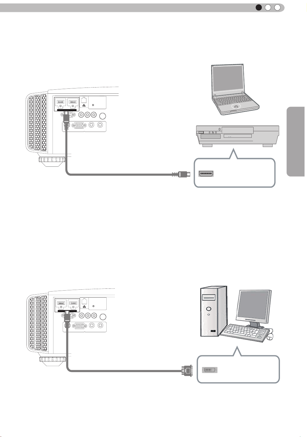
■
Connecting via HDMI Cable
ENGLISH
This unit
Notebook PC
BD/DVD recorder
HDMI 1 input terminal
HDMI 2 input terminal
HDMI output terminal
HDMI cable (sold separately)
●
If noise is produced, take PCs (Notebook PC) away from this unit.
●
For a transmission bandwidth in compliance with the HDMI standard, a 340MHz cable is recommended.
In case a cable is used for transmission bandwidth of 75MHz, it is recommended to choose 1080i or less
for the transmitting equipment.
●
If the video is not displayed, try to reduce the length of the cable or lowering the resolution of the video
transmitting equipment.
Preparation
■
Connecting via HDMI-DVI Conversion Cable
This unit
Desktop computer
HDMI 1 input terminal
HDMI 2 input terminal
●
If noise is produced, take PCs (desktop computer) away from this unit.
●
If the video is not displayed, try to reduce the length of the cable or lowering the resolution of the video
transmitting equipment.
HDMI-DVI conversion cable
(sold separately)
DVI output terminal
29
Page 30

2
C
Preparation
About the connection (Continued)
Connecting via Component Video Cable
■
This unit
STANDBY/ON
INPUT
OK
1 HDMI 2
RS-232-C
3D
SYNCHRO
C
R/PR CB/PB Y
PC
TRIGGER
REMOTE
CONTROL
MENU BACK
To component video input terminals
Component video cable
(sold separately)
●
Set “COMP.” in the setting menu to “Y Pb/Cb Pr/Cr”.
(Reference page: 60)
BD/DVD player
Component video output terminals
C
R/PR
C
B/PB
Y (green)
(red)
(blue)
■
Connecting via RGB Video Cable
This unit
STANDBY/ON
1 HDMI 2
RS-232-C
3D
SYNCHRO
C
R/PR CB/PB Y
PC
REMOTE
TRIGGER
CONTROL
To RGB video input terminals
INPUT
OK
MENU
BACK
RGB video cable
(sold separately)
●
Set “COMP.” in the setting menu to “RGB”. (Reference page: 60)
●
For information on compatible input signals, see “Specifications”. (Reference page: 92)
Device equipped with
RGB output
RGB video output terminals
R(Red)
B(Blue)
G(Green)
signals)
(Includes sync
30
Page 31

About the connection (Continued)
1 HDMI 2
RS-232-C
3D
C
R/PRCB/PB
Y
SYNCHRO
PC
TRIGGER
REMOTE
CONTROL
STANDBY/ON
MENU
BACK
INPUT
OK
1 HDMI 2
RS-232-C
3D
C
R/PRCB/PB
Y
SYNCHRO
PC
TRIGGER
REMOTE
CONTROL
STANDBY/ON
MENU
BACK
INPUT
OK
■
Connecting via PC Cable
This unit
To PC input terminal
PC cable(sold separately
●
For information on supported input signals, please refer to “Specications
90
70
Notebook PC
)
VGA output terminal
(Reference page: 92)
”.
ENGLISH
Preparation
■
Connected by a 3D SYNCHRO terminal
This unit
3D-glasses
3D synchro emitter
●
3D synchro emitter: This is a dedicated terminal for PK-EM1 (sold separately).
●
The PK-EM1 infrared sometimes affects other infrared communication devices.
●
3D glasses (PK-AG1-B, PK-AG2-B) is an optional device, and is not included in the 3D synchro emitter.
Note that converting 2D images to 3D ones using the 3D feature of this product, and playing them for
●
commercial purposes or for broadcasting in public places may infringe the rights of authors protected
under the copyright laws.
3D i
●
CAUTION
mages may appear different depending on the ambient temperature and lamp usage. Stop using the
projector if images cannot be projected correctly.
Before you watch 3D video images, make sure to read "3D description of the system".
●
(Reference page: 75 to 77)
31
Page 32

2
1 HDMI 2
RS-232-C
3D
C
R/PRCB/PB
Y
SYNCHRO
PC
TRIGGER
REMOTE
CONTROL
STANDBY/ON
MENU
BACK
INPUT
OK
1 HDMI 2
3D
C
R/PRCB/PB
Y
SYNCHRO
PC
TRIGGER
REMOTE
CONTROL
STANDBY/ON
MENU
BACK
INPUT
OK
Preparation
About the connection (Continued)
■
Connecting via Trigger Cable
This unit
Screen
To Trigger output terminal
Tr
igger cable
(sold separately)
CAUTION
Trigger input terminal
(Φ3.5)
●
Do not supply the power to the other devices.
●
Do not connect audio terminals of the other devices such as headphones etc. Otherwise, this may
cause a malfunction of the other devices or injury.
●
Using beyond the rated value will cause malfunction.
● Exercise adequate caution to prevent short circuit as the trigger terminal outputs a voltage of 12V.
●
The default is set to "No output". Please set it under the item "Trigger" of menu [5] "Function". (Reference
page: 72)
■
Connected by RS-232C connection cable
This unit
RS-232C connection cable (sold separately)
RS-232C
terminal
32
Page 33

ENGLISH
1 HDMI 2
RS-232-C
3D
C
R/PR CB/PB Y
SYNCHRO
PC
TRIGGER
REMOTE
CONTROL
STANDBY/ON
MENU
BACK
INPUT
OK
About the connection (Continued)
■
Connected by LAN terminal
This unit
HUB
connection cable
(sold separately)
STANDBY/ON
1 HDMI 2
C
R/PR CB/PB Y
RS-232-C
3D
SYNCHRO
●
The network is used to control the unit. It is not used for transmission of the video signal.
●
Please contact your network administrator for questions concerning the network connection.
REMOTE
TRIGGER
PC
CONTROL
INPUT
OK
MENU
BACK
Network
Preparation
Server
■
Connected by a REMOTE terminal
This unit
External infrared sensor
connection cable(sold separately)
●
For an external infrared sensor and connecting cable, please contact your dealer.
(sold separately)
33
Page 34

2
1 HDMI 2
RS-232-C
3D
C
R/PRCB/PB
Y
SYNCHRO
PC
TRIGGER
REMOTE
CONTROL
STANDBY/ON
MENU
BACK
INPUT
OK
Power Cord
(Supplied)
Preparation
About the connection (Continued)
Connection of the power cord (provided)
Once you have connected the equipment, connect the projector power cord.
1 Connect the power cord supplied with the
unit power input terminal
2 Connect to the power outlet
1
2
Be carful to avoid re and electric shocks
● As the amount of electrical energy for this unit is large, please connect it directly into
the wall outlet.
CAUTION
● When you are not using the equipment, please unplug the power cord.
● Connect it only with the provided power cord.
● Do not use voltage other than the indicated power voltage.
● Do not damage, break or modify the power cord. Moreover, the power cord will be
damaged if you place it under heavy objects, heat or pull it.
● Do not unplug with wet hands.
34
Page 35

MEMO
ENGLISH
Preparation
35
Page 36

3
INPUT
LENS
LENS
BACK
HIDE
LIGHT
LENS
MEMORY
ANAMO.
PC
HDMI 1
STAND BY
3D
FORMAT
HDMI 2
3D
SETTING
COMP
.
LENS.
CONTROL
MENU
ON
INPUT
GAMMA
P.FILE
COLOR
ADJ.
PIC.
FILM
NATURAL
STAGE 3D
THX
USER
C.M.D.
ANIME
CINEMA
PICTURE MODE
TEMP
COLOR
Operation
Basic Operation
Basic operation procedures
6
1
2
3
4
5
Once you have finished the basic setup, the unit can normally be
used just with the following operations.
Turn on power source
1
ON
STANDBY/ON
Light on (Green)
●
You can also press the
on the power
●
The lens cover will be opened.
. (Reference page: 16)
Remove the lens cover.
button on the unit to turn
70
90
X
30
(*) Be sure to remove the lens cover when you use the
product Projection without removing the lens cover
may cause the product to malfunction.
Choose the projected image
2
1
Select input mode
●
You can also select the input mode by pressing the
button on the unit. (Reference page: 16)
HDMI 1
HDMI 2 COMP. PC
36
70
90
X
30
arrangement is used for the
: The same button
operations in this explanation.
WARNING
LAMP
STANDBY/ON
Play back the selected device
2
Adjust the zoom (screen size)
3
Lens Control
Zoom
Select
Back
Exit
MENU
Operate
4
Adjust the focus (focal point)
Lens Control
Focus
Select
Back
Exit
MENU
Operate
Adjust accordingly
BACK
by pressing the up/
down buttons
Adjust accordingly
BACK
by pressing the
up/down buttons
Page 37

Adjust the shift (image position)
OK
)RFXV =RRP
6KLIW
LENS
LENS
5
Lens Control
ENGLISH
Shift
●
After adjusting the image position, it may be necessary to
select “Pixel Adjust” from the Settings menu “Installation”.
(Reference page: 66
●
Every time the
to 67
LENS
button is pressed, the adjustment
item will be switched among “Focus”, “Zoom” and “Shift”.
Turn off power source
6
It can also be switched with the button.
STAND BY
While a confirmation screen is displayed
STAND BY
STAND BY/ON
Blinking (Red Lamp)
Select
Operate
)
Back
MEMO
About Cool Down
BACK
Adjust accordingly
by pressing the
up/down/left/right
buttons
mode
●
The Cool Down mode is a
function to cool down the lamp
for approximately 60 seconds
after projection is complete.
This function prevents the
internal parts of the unit from
deformation or damage due to
overheating of the lamp. It also
prevents lamp blowout and
premature shortening of lamp
life.
●
During Cool Down mode, the
[STANDBY/ON] indicator blinks
in red.
●
After the Cool Down mode is
complete, the unit automatically
returns to standby mode.
●
Do not pull out the power plug
during Cool Down mode. This
may shorten the lamp life and
cause a malfunction.
●
The slide cover will not close
if the [Slide Cover] is set to
[Open] in the [3. Setup] [3-1. Lens Control] menu.
(Reference page: 66)
Operation
Cool Down mode
STAND BY/ON
Light on (Red Lamp)
●
When power off, the lens cover will be closed.
●
Set the lens cover.
●
You can also press the
the power. (
●
Pull out the power plug when the unit will not be used for a
Reference page: 16
X
30
button on the unit to turn off
)
90
70
prolonged time.
37
Page 38

3
Picture Adjust
Reset
Advanced
Exit
MENU
BACK
Back
Select
Operate
Color Temp.
Gamma
Dark/Bright Level
Picture Tone
Contrast
Brightness
Color
Tint
0
0
0
0
Color Profile
Picture Mode
Natural
Video
6500K
Normal
7
Operation
Basic Operation (continued)
Frequently used useful functions
u can change the screen size of the projected image or
Yo
hide the surrounding area of an image for which quality at the
outer area has deteriorated.
A
Setting the Screen Size
Masking the Surrounding Area of an Image
B
C
Temporary turning-off of the video
Adjustment of the keystone correction
D
A
Setting the Screen Size
The projected image can be set to a most appropriate screen
size (aspect ratio).
“
● When PC signals are input, the
spect(Computer)” setting will be
A
available instead. (Reference page: 60)
■ Input Image and Projected Image by Different Screen
Size
Project the image
1
INPUT
HDMI 2
3D
SETTING
LENS
MEMORY
ON
COMP
PC
ANAMO.
.
LIGHT
STAND BY
HDMI 1
3D
FORMAT
LENS.
CONTROL
HIDE
A
38
COLOR
P.FILE
BACK
ANIME
C.M.D.
PIC.
ADJ.
MENU
PICTURE MODE
CINEMA
FILM
NATURAL
STAGE 3D
THX
USER
COLOR
GAMMA
TEMP
70
90
X
: The same button
30
arrangement is used for the
operations in this explanation.
Aspect the image
2
Display the setting menu
1
MENU
2
Select “Input Signal
① Select
② Confirm
4:3 video signal
“Aspect (Video)”
”
Input Signal
HDMI
COMP.
PC
Picture Position
Aspect (Video)
Mask
Progressive
3D Setting
Exit
MENU
Select
4:3
off
Auto
Operate
Back
BACK
16:9
Custom
4:3
Page 39

3
MENU
Set a Aspect value
ENGLISH
Example:
When the “Aspect” value is
“
changed from “4
:3”
16:9
① Select
② Confirm
”
● Depending on the input image, selecting
vertically stretched image, while selecting “16:9” provides you
with the most appropriate screen size.
● When there is 3D signal input, the ratio is fixed to
Input Signal
HDMI
COMP.
PC
Picture Position
Aspect (Video)
Mask
Progressive
3D Setting
Select
Operate
“
16:9”.
Exit
MENU
To end
3
“
4:3” may result in a
16:9
4:3
off
16:9
Auto
Custom
Back
BACK
Operation
39
Page 40

3
Picture Adjust
Reset
Advanced
Exit
MENU
BACK
Back
Select
Operate
Color Temp.
Gamma
Dark/Bright Level
Picture Tone
Contrast
Brightness
Color
Tint
0
0
0
0
Color Profile
Picture Mode
Natural
Video
6500K
Normal
Exit
MENU
BACK
Back
Select
Operate
Aspect (Video)
Progressive
3D Setting
HDMI
COMP.
Auto
PC
Picture Position
16:9
Off
Mask
2.5%
5%
Off
Custom
Input Signal
Exit
MENU
BACK
Back
Select
Operate
Aspect (Video)
Progressive
3D Setting
HDMI
COMP.
Auto
PC
Picture Position
16:9
5%
Mask
2.5%
5%
Off
Custom
Input Signal
MENU
7
Operation
MEMO
●
Mask i ng is av a ilab l e only
when high definition images
are input.
INPUT
HDMI 2
3D
SETTING
LENS
MEMORY
ON
COMP
PC
ANAMO.
.
LIGHT
STAND BY
HDMI 1
3D
FORMAT
LENS.
CONTROL
HIDE
B
Masking the Surrounding Area of an Image
Images for which quality at the outer area has deteriorated
can be projected by masking (hiding) the surrounding area of
the projected image.
Project the image
1
Image for which quality at the
outer area has deteriorated.
2
Mask the image
Display the setting menu
1
MENU
B
COLOR
P.FILE
BACK
ANIME
C.M.D.
ADJ.
MENU
PICTURE MODE
CINEMA
FILM
NATURAL
STAGE 3D
THX
USER
COLOR
GAMMA
TEMP
70
90
X
X
: The same button
30
arrangement is used for the
operations in this explanation.
(*) When there is a 3D input
signal, adjustment is not
possible.
2
Select “Input Signal” “Mask
”
① Select
PIC.
② Confirm
3
Set a mask value
① Select
② Confirm
40
Example:
When the “M
changed from “O
ask” value is
“5%”
ff”
3
To end
Page 41

ENGLISH
Picture Adjust
Reset
Advanced
Exit
MENU
BACK
Back
Select
Operate
Color Temp.
Gamma
Dark/Bright Level
Picture Tone
Contrast
Brightness
Color
Tint
0
0
0
0
Color Profile
Picture Mode
Natural
Video
6500K
Normal
MENU
7
Basic Operation (continued)
C
Temporary turning-off of the video
You can hide the image temporarily.
INPUT
HDMI 2
3D
SETTING
LENS
MEMORY
ON
COMP
PC
ANAMO.
STAND BY
HDMI 1
3D
FORMAT
LENS.
CONTROL
C
HIDE
D
USER
COLOR
P.FILE
BACK
ANIME
C.M.D.
MENU
PICTURE MODE
CINEMA
FILM
NATURAL
STAGE 3D
THX
COLOR
GAMMA
TEMP
70
90
X
: The same button
30
arrangement is used for the
operations in this explanation.
LIGHT
PIC.
ADJ.
HIDE
Green light blinks
when the image is
hidden.
.
●
Press the
●
The power cannot be turned off when the image is temporarily
HIDE
button again to display image.
hidden.
D
Adjustment of the keystone correction
In regards to the projection plane, any occurring keystone distortion
is adjusted in case the installation location is inclined.
Display the setting menu
1
MENU
Operation
2
Select “Installation
① Selec
3
Adjusts keystone correction
If one presses the cursor (vertical and horizontal arrows) in the
keystone correction mode, the keystone distortion can be adjusted.
”
“Keystone
② Confirm
”
Installation
Lens Control
Pixel Adjust
Installation Style
Keystone
Anamorphic
Screen Adjust
Black Level
Exit
MENU
Select
Operate
Front
Off
Back
BACK
●
When there is a 3D input
signal, adjustment is not
possible. Moreover, even if
the keystone correction is
adjusted, keystone correction
is removed when there is a 3D
input signal.
Adjust horizontal distortion with the
cursors for left and right.
Exit
4
Adjust vertical
distortion with
the cursors for
up and down.
41
Page 42
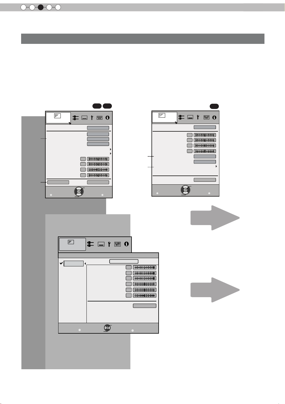
3
Picture Adjust
Reset
Advanced
Exit
MENU
BACK
Back
Select
Operate
Color Temp.
Gamma
Dark/Bright Level
Picture Tone
Contrast
Brightness
Color
Tint
0
0
0
0
Color Profile
Picture Mode
Natural
Video
6500K
Normal
>
Color Temp.
Gain Red
Gain Green
Gain Blue
Offset Red
Offset Green
Offset Blue
Preset
Custom1
Custom2
Custom3
Picture Adjust
6500K
Exit
MENU
BACK
Back
Select
Operate
Reset
0
0
0
0
0
0
Operation
Adjustments and settings in the menu
Structure of the menu hierarchy (summary)
The Menu of this unit is organized as follows. As this is only a brief guideline, items, which might not be
displayed due to certain settings, are still displayed in the illustration. Moreover, in regard to , it shows
countermeasures for all kinds of devices, but there the values for setting and adjustment might be different.
See “Description of menu items” (Reference: Since 52 and following) for details. It can be moved to
subscreens used for adjustment, even for items that do not feature submenus.
[1] Picture Adjust
70
[1-1]
90
[1-1]
[1-2]
Picture Adjust
Picture Mode
Contrast
Brightness
Color
Tint
Color Temp.
Gamma
Advanced
0
0
0
0
30
Natural
6500K
Normal
42
[1-2]
[1-1] Color Temp.
Continue to the next
Exit
MENU
Select
Reset
Operate
P. 52
P. 55
Back
BACK
Page 43

ENGLISH
Exit
MENU
BACK
Back
Select
Operate
0
>
>
25
Detail Enhance
Sharpness
Picture Adjust
Sharpness
Adjustments and settings in the menu (continued)
[1-2] Advanced
90
70
30
[1-2-1]
[1-2-2]
[1-2-3]
Picture Adjust
>
Advanced
Sharpness
NR
Custom Gamma
Color Management
User Name Edit
Clear Motion Drive
CMD Demo
Lens Aperture
Lamp Power
Exit
MENU
Select
[1-2-1] Sharpness
0
Operate
Off
Off
Normal
Back
BACK
[1-2-1]
[1-2-2]
Picture Adjust
>
Advanced
Sharpness
NR
Color Space
Custom Gamma
User Name Edit
Clear Motion Drive
CMD Demo
Lens Aperture
Lamp Power
Exit
MENU
Select
0
Operate
P. 56
Standard
Off
Normal
Back
BACK
Operation
P. 58
Continue to the next
43
Page 44

3
Color Management
Color Selection
Axis Position
Hue
Saturation
Brightness
Off
Custom1
Custom2
Custom3
Picture Adjust
Exit
MENU
BACK
Back
Select
Operate
0
0
0
0
Pause
Off
Reset
Red
>
>
Custom Gamma
Correction Value
White
Red
Green
Blue
Reset
1023
512
50
100(%)
Custom1
Custom2
Custom3
0
Picture Adjust
Exit
MENU
BACK
Back
Select
Operate
Normal
>
>
Operation
Adjustments and settings in the menu (continued)
[1-2-2] Custom Gamma
P. 58
[1-2-3] Color Management
70
90
44
P. 59
Page 45

ENGLISH
Input Signal
3D Setting
Parallax
On
2D/3D
Crosstalk Cancel
Auto
3D Format
0
Intensity
Sub Title Adjust
1
Exit
MENU
BACK
Back
Select
Operate
On
Exit
MENU
BACK
Back
Select
Operate
Level Check
Input Signal
HDMI
Off
Control with HDMI
Auto
Color Space
Standard
Input
Exit
MENU
BACK
Back
Select
Operate
Aspect(Video)
Progressive
3D Setting
HDMI
COMP.
Mask
Auto
Picture Position
16:9
Off
Input Signal
Adjustments and settings in the menu (continued)
[2] Input Signal
When inputting 2D signals
Input Signal
HDMI
[2-1]
COMP.
[2-2]
[2-3]
(*)
PC
Picture Position
Aspect(Video)
Mask
Progressive
3D Setting
90
70
16:9
Off
Auto
When inputting 2D signals
30
[2-1]
[2-3]
Exit
MENU
Select
Operate
Back
BACK
(*) When there is a PC signal
input, “Aspect (PC)” is
displayed.
The "Input Signal" menu display during 3D signal input
is the same as the menu display for "[2-3] 3D Setting".
[2-1] HDMI
P. 60
Operation
P. 63
Continue to the next
P. 61
45
Page 46

3
Input Signal
3D Setting
Parallax
On
2D/3D
Crosstalk Cancel
Auto
3D Format
0
Intensity
Sub Title Adjust
1
Exit
MENU
BACK
Back
Select
Operate
On
Exit
MENU
BACK
Back
Select
Operate
Input Signal
PC
16
Phase
880
Tracking
Picture Position
Auto Alignment
Operation
Adjustments and settings in the menu (continued)
[2-2] PC
70
90
P. 62
[2-3] 3D Setting
P. 63
46
Page 47

ENGLISH
Exit
MENU
BACK
Back
Select
Operate
Pixel Adjust
Installation
Lens Control
Keystone
Anamorphic
Screen Adjust
Black Level
Installation Style
Front
Off
Exit
MENU
BACK
Back
Select
Operate
Lock
Lens Memory Select
Lens Memory Save
Zoom
Shift
On
Image Pattern
Auto
Lens Cover
Installation
Lens Control
Focus
Lens Memory Name Edit
Off
Exit
MENU
BACK
Back
Select
Operate
Lock
Lens Memory Select
Lens Memory Save
Zoom
Shift
On
Image Pattern
Installation
Lens Control
Focus
Lens Memory Name Edit
Off
Installation
Exit
MENU
BACK
Back
Select
Operate
Adjust Area
Adjust Color
Pixel Adjust
Adjust Pattern Color
Adjust(Pixel)
Adjust(Fine)
Adjust
On
Whole
Red
White
Reset
Horiz. Blue
Pixel Adjust
Vert. Red
Vert. Blue
3
3
3
Horiz. Red
3
Installation
Exit
MENU
BACK
Back
Select
Operate
Adjustments and settings in the menu (continued)
[3] Installation
[3-1]
[3-2]
P. 64
[3-1] Lens Control
90
70
30
[3-2] Pixel Adjust
90
70
Operation
P. 65
30
P. 66 to 67
47
Page 48
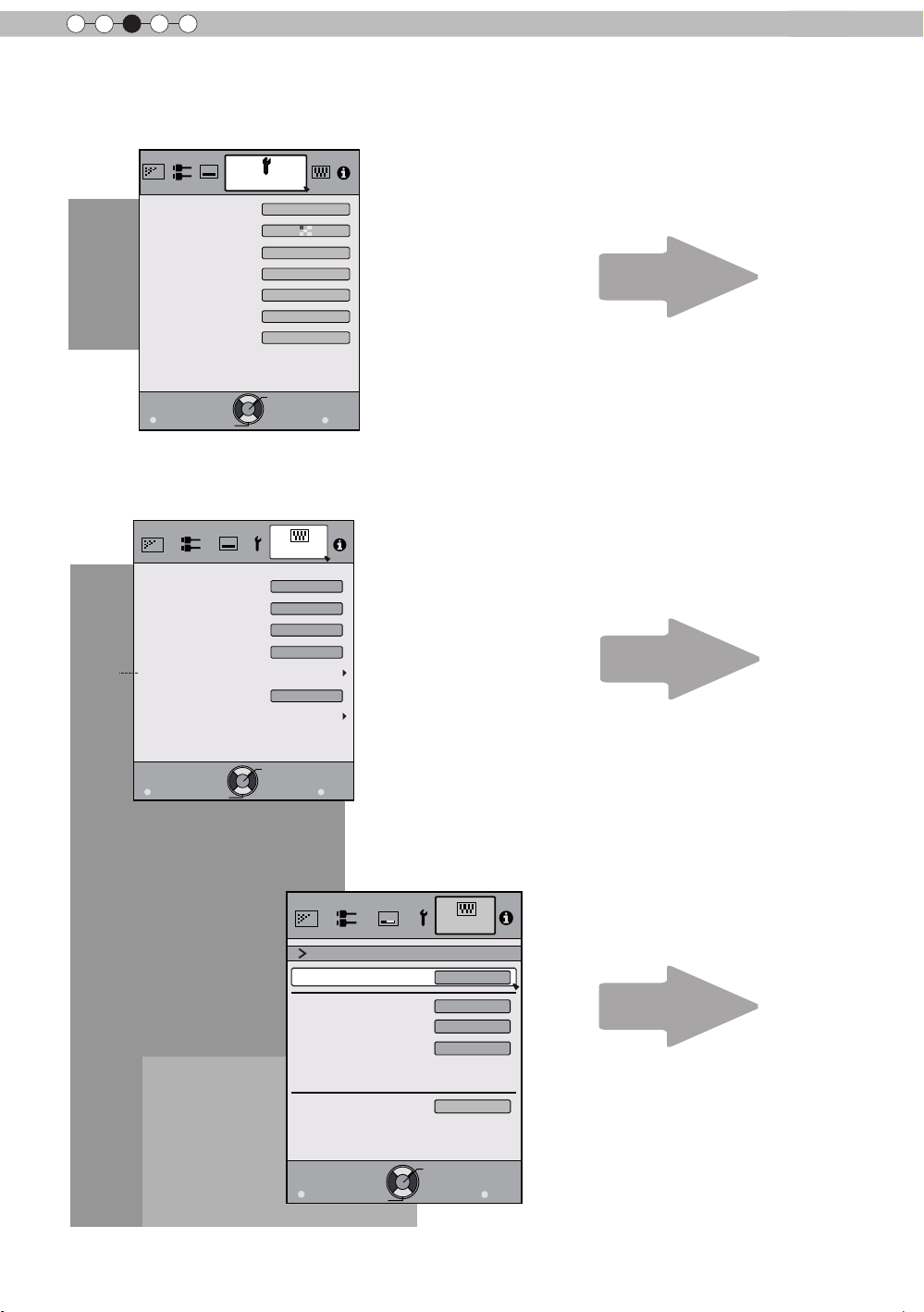
3
Exit
MENU
BACK
Back
Select
Operate
IP Address
Subnet Mask
Default Gateway
Network
DHCP Client
On
Function
Set
MAC Address :
AA-BB-CC-DD-EE-FF
192. 168. 0.254
255. 255. 255. 0
192. 168. 0. 2
Exit
MENU
BACK
Back
Select
Operate
Trigger
Off Timer
Remote Code
Network
Lamp Reset
Remote Code
High Altitude Mode
Off
Off
Off
Function
RS-232C
A
Exit
MENU
BACK
Back
Select
Operate
Display Setup
Back Color
Menu Display
Menu Position
On
Line Display
5sec
Source Display
On
Logo
On
Language
English
Black
Operation
Adjustments and settings in the menu (continued)
[4] Display Setup
P. 71
[5] Function
[5-1]
P. 72
[5-1] Network
P. 73
48
Page 49

ENGLISH
Exit
MENU
BACK
Back
Select
Operate
160H
HDMI-2
1080p60
8bit
Input
Source
Deep Color
Lamp Time
12.011
Soft Ver.
Information
:
:
:
:
:
Adjustments and settings in the menu (continued)
[6] Information
When inputting HDMI signals
P. 73
When inputting PC signals
70
90
Input
Resolution
H Frequency
V Frequency
Deep Color
Lamp Time
Soft Ver.
Exit
MENU
Select
:
:
:
:
:
:
:
Information
1920X1080
67.50kHz
60.0Hz
160H
12.011
Operate
Operation
PC
8bit
Back
BACK
P. 73
49
Page 50

3
STANDBY/ON
MENU
BACK
INPUT
OK
Operation
Adjustments and settings in the menu (continued)
Menu operation button
Operate the menu by use of the buttons on the main body or the
remote control.
Button
This unit Remote Control
MENU
OK OK
BACK
This unit
Remote Control
MENU
BACK
Function
Menu is displayed.
While the menu is displayed,
the me nu screen is turned off.
While showing "Main menu" (Layer 1)
selected items are confirmed, and
"Submenu" (Layer 2) will be displayed.
When the submenu is displayed, press
OK, and the displayed items in the
selection are moved to the
"Setting screen" (Layer 3).
Return to the previous menu screen.
The menu screen is turned off when
the main menu screen is shown.
Displaying the main menu and the
submenu
Select an adjustment item in the
:/
menu. Set the setting value of the
selected adjustment item. The
adjusted setting value is immediately
reflected in the image.
:
/
Selection of a displayed sub-menu
item. Selection of an item in the
menu.
STAND BY
HDMI 1
3D
FORMAT
LENS.
CONTROL
HIDE
MENU
FILM
NATURAL
THX
GAMMA
INPUT
HDMI 2
3D
SETTING
LENS
MEMORY
PICTURE MODE
CINEMA
STAGE 3D
USER
COLOR
COLOR
TEMP
P.FILE
ON
ANAMO.
COMP
PC
LIGHT
BACK
ANIME
C.M.D.
.
PIC.
ADJ.
Menu
operation
buttons
Menu
operation
buttons
50
70
90
X
: The same button
30
arrangement is used for the
operations in this explanation.
Page 51

ENGLISH
STANDBY/ON
MENU
BACK
INPUT
OK
Exit
MENU
BACK
Back
Select
Operate
160H
HDMI-2
1080p60
8bit
Input
Source
Deep Color
Lamp Time
12.011
Soft Ver.
Information
:
:
:
:
:
Exit
MENU
BACK
Back
Select
Operate
Lamp Time
Deep Color
160H
PC
1920X1080
Information
Resolution
67.50kHz
H Frequency
60.0Hz
V Frequency
Input
:
:
:
:
:
:
8bit
12.011
Soft Ver.
:
7
90
70
Adjustments and settings in the menu (continued)
Menu operation procedure
1 Press MENU.
The main menu is displayed on the screen.
Picture Adjust
Picture Mode
Color Profile
Color Temp.
Gamma
Dark/Bright Level
Picture Tone
Contrast
Brightness
Color
Tint
Advanced
Exit
0
0
0
0
Select
Operate
MENU
Example: Picture Adjust
The submenu items, which are currently
selected, are shown. Currently selected menu
Natural
items are highlighted and the icon is colored
Video
6500K
in orange.
Normal
The submenu items, which are currently
selected, are displayed.
Reset
Back
BACK
This displays the remote control operation
guide.
1
3
3,4
2,5
1
INPUT
HDMI 2
3D
SETTING
LENS
MEMORY
ON
STAND BY
HDMI 1
3D
FORMAT
LENS.
CONTROL
HIDE
COMP
PC
ANAMO.
LIGHT
6
.
3,4
2,5
3
CINEMA
STAGE 3D
USER
COLOR
P.FILE
BACK
ANIME
C.M.D.
6
PIC.
ADJ.
MENU
PICTURE MODE
FILM
NATURAL
THX
COLOR
GAMMA
TEMP
70
90
X
: The same button
30
arrangement is used for the
operations in this explanation.
2 Press cursor ( / ) to select a submenu.
● A submenu (picture adjust, input signal, installation, display
setup, function, information) is selected:
● If one selects "Information", information about the currently
selected video input and PC input are displayed at the bottom
of the menu.
3 Press OK or cursor ( / ).
● Sub-menu item is displayed.
● Sub-menu items vary depending on the input signal and the
picture mode. See "Content menu" on the next page for more
details.
Example: Input of signals
other than PC signals
Example: When inputting
PC signals
4 Press the cursor ( / ) to select the items to
adjust.
If the name of a submenu item is displayed in a dimmed manner,
it cannot be selected.
5 Press cursor ( / ) to change settings.
6 After adjusting, press BACK.
Every time it is pressed, you will return to the respective previous
menu screen.
7 Repeat steps 6-2 to adjust other items.
After all adjustments are done, press MENU, and the menu
disappears from the screen.
Operation
51
Page 52

3
Operation
Adjustments and settings in the menu (continued)
Menu item description
All numbers for the items within [ ]are default settings.
● It is possible to operate all items displayed in the menu display by pressing OK/BACK or the cursor (up,
down, left, right arrows).
● Displayed items vary depending on the selected item in the menu and type of input signal or absence of
any signal.
[1] Picture Adjust
Adjust the video image contents and projector projection environment picture to
your preferred color, gamma, brightness and other settings.
Use the UP and DOWN keys to select items. Press the [BACK] key to return to
the previous screen.
Picture Mode
Color Profile
Color Temp.
Gamma
Dark/Bright Level
Picture Tone
Contrast
Brightness
Color
Tint
Advanced
Items Explanation, operation, precautions, settings
Picture Mode
Please refer to the description of each mode, and then use the mode to best suited for
you. Moreover, it is possible to adjust the image quality by using a User 1-5.
Settings: Film, Cinema, Animation, Natural, Stage, 3D, THX, User 1-5.
[Natural]
Film This quality setting is similar to the texture of the lm setting. It is suitable for watching
movies in general.
Cinema
This image setting is based on the DCI standard and brings to life brightly colored
pictures. Suitable for viewing action movies and brightly colored images.
DCI: Shorthand for Digital Cinema Initiatives.
Animation
Natural
An image quality setting for watching animation movies and the like.
It is an image quality setting with natural color/tone. Suitable for viewing video material,
such as dramas/serials.
Stage
3D
THX
User 1
User 2
User 3
90
70
This image quality setting is suitable for watching of live events, e.g. on a stage.
This is an image quality setting for watching 3D movies.
It is an image setting certied by the company THX.
The User 1-5 should adjust the image quality as desired in each case. Data of the last
adjustment is saved. Edit to set your preferred your username using the "[1-2] Advanced"
"User Name Edit" function.
User 4
User 5
Color Profile
70
90
It selects a color prole to suit the input source. Depending on the settings, the items that
can be set in the "Picture Mode" vary. (See Table 1)
The color prole is selected based on the video production. We recommend to match the
color prole of the video you want to watch.
(*) If you select "Off", it is impossible to perform any picture adjust for other color temp.
other than "Lamp power" and "Lens aperture" under "Advance", and also not gamma or
sharpness.
Setting: Film 1, Film 2, Cinema 1, Cinema 2, Standard, Anime 1, Anime 2, Video, Vivid,
Adobe, Stage, 3D, Off, Custom 1-5.
[Depending on the picture mode, the default values will change. (See Table 1)]
Film 1 This is a prole that comes close to a color space that resembles using a Xenon lamp to
transmit a lm used for movies by the Eastman Kodak Company.
Film 2 This is a prole that comes close to a color space that resembles using a Xenon lamp to
transmit a lm used for movies by the FUJIFILM Corporation.
Cinema 1
Cinema 2
Standard
This is a prole that resembles the color space of the DCI standard.
This is a prole that resembles the color space of HDTV.
It is a prole with an especially rich representation of the lm-specic colors.
HDTV: Shorthand for High Denition Television.
Natural
Video
6500K
Normal
0
0
0
0
Reset
52
Page 53

ENGLISH
Adjustments and settings in the menu (continued)
Anime 1
Anime 2
Video
Vivid
Adobe
Stage
3D
Off
Custom 1
Custom 2
Custom 3
Custom 4
Custom 5
This is a prole suitable for CG-animations, which can be often found in Hollywood-
produced animated series.
It is intended for animations with multiple bright colors.
This is a prole suitable for animation cel-style animation series, which are common in
Japan.
It is intended for animations with many dim colors.
This prole is suitable e.g. for TV / drama / sports.
This is a prole with rich sense of color, which makes it suitable for games.
This is the color prole for Adobe RGB.
(*) Adobe, and the Adobe logo are registered trademarks or trademarks of Adobe
Systems Incorporated in the United States and/or other countries.
This prole is suitable for live music, orchestra and opera concerts, theater, etc.
This is the most suitable prole when using 3D-glasses.
It is a mode that does not adjust the color management.
You can install the color prole supplied by this JVC. The name changes after
installation.
90
[Table 1] The setting contents and default values of the color proles for the picture mode
Picture Mode
Film Cinema Anime Natural Stage 3D THX
Film 1 Cinema 1 Anime 1 Video Stage 3D THX
Color Prole
Film 2 Cinema 2 Anime 2 Vivid Standard Standard
Standard Standard Adobe Vivid
Standard
User 1,
2,3,4,5
Everything
is displayed
except for
Film 1,2
and THX.
Operation
This is the default value according to the picture mode.
53
Page 54

3
Operation
Adjustments and settings in the menu (continued)
Color Temp.
Gamma
Normal
A (3D)
B (3D)
Film 1 This is a gamma curve that approximates the characteristics of an Eastman Kodak
Film 2 This is a gamma curve that approximate the gamma curve characteristics of a
Film 3 This is a gamma curve that is even more focused on tone for the gamma of Film 1.
Film 4 This is a gamma curve that emphasizes more contrast for the gamma of Film 2.
A
B
C
D
Custom 1
Custom 2
Custom 3
Dark/Bright Level
Dark Level
Bright Level
Picture Tone
White
Red
Green
Blue
Contrast
Brightness
Color
Tint
Advanced
Reset
It is possible to set the color temp.
To "[1-1] Color Temp." of the submenu
It is possible to set the gamma curve. Please set to your preference.
Settings: Normal, A (3D), B (3D), Film 1, Film 2, Film 3 Film 4, A, B, C, D, Custom 1,
Custom 2, Custom 3 [Normal]
Typically we recommend this setting.
(*) You cannot congure Normal Mode when the "Picture Mode" is set to "Film" or "3D".
A (3D), B (3D) can only be set, if the "Picture Mode" is "3D".
This is a standard gamma curve for 3D.
A (3D) will be brighter.
Film 1, 2, 3, 4 can only be set if the "Picture Mode" is set to "Film" .
Company lm for movies.
cinematographic lm made by the FUJIFILM Corporation.
(*)You cannot congure A, B, C, and D when the "Picture Mode" is set to "Film" or "3D".
In regard to normal gamma, this is a gamma curve focused on tone.
This is a gamma curve for the lm's unique S curve.
This is a gamma curve that – in regard to the gamma of B – emphasized even more the
feeling of contrast.
For normal, this is a gamma curve where the intermediate gradations look very bright.
(*) Custom 1, 2, 3 cannot be congured during 3D signal input and when the "Picture
Mode" is set to 3D.
Under submenu "[1-2-2] Custom Gamma", it is possible to change the gamma curve and
save it.
The initial value of Custom 1, 2, and 3 is the same as for "Normal".
Compensating darkness / brightness of an area.
(*) It is possible to set it unless the "Picture Mode" is set to "Film".
Settings: (makes dark areas darker) -7 to 7 (brightens dark areas) [0]
Settings: (darkens bright areas) -7 to 7 (makes bright areas brighter) [0]
You can reproduce the intensity of the exposure image.
(*) This function can be congured when the "Picture Mode" is set to "Film" and "Gamma"
is set to "Film 1-4".
(*) "Video Tone" is displayed when the "Picture Mode" setting is anything except "Film".
Settings: (The more under-exposure, the darker) -16 to 16 (the more over-exposure, the
brighter) [0]
Settings: (under-exposure to for red), -16 to 16 (over-exposure for red) [0]
Settings: (under-exposure for green) -16 to 16 (over-exposure for green) [0]
Settings: (under-exposure for blue) -16 to 16 (over-exposure for blue) [0]
Adjusts the contrast of the video images.
Settings: (blackish) -50 50 (whitish)
You can adjust the brightness of the video image.
Settings: (dark) -50 to 50 (bright)
Adjust the color intensity of the video images.
Settings: (dim), -50 to 50 (saturated)
Adjusts the image tint of the video images.
Settings: (reddish) -50 to 50 (greenish)
Functions such as contour correction, custom gamma and color management can be set
to sub-menu "[1-2] Advanced".
Sets settings to default factory settings.
90
70
54
Page 55

ENGLISH
Adjustments and settings in the menu (continued)
[1-1]
Color Te
Use this function to se the video image color temperature. Adjust according to
your preference.
(*) The settings available will vary depending on the "Picture Mode". However,
settings cannot be adjusted when "Picture Mode" is set to "THX".
Use the UP and DOWN keys to select items. Press the [BACK] key to return
to the previous screen.
Items Explanation, operation, precautions, settings
Preset
(Preset value)
(Preset value)
Xenon1
Xenon2
Xenon3
(Preset value)
Custom 1
Custom 2
Custom 3
Gain
Offset
mp.
Red
Green
Blue
High Bright
70
90
Red
Green
Blue
Red
Green
Blue
Red
Green
Blue
>
Color Temp.
Preset
Custom1
Custom2
Custom3
Gain Red
Gain Green
Gain Blue
Offset Red
Offset Green
Offset Blue
6500K
0
0
0
0
0
0
Reset
Set the color temp. of the video images.
Please adjust to your preference.
(*) For this setting, the setting items can differ in accordance with the "Picture Mode".
Adjustment is not possible when set to “THX".
Settings: (Preset value), Xenon1, Xenon2, Xenon3, High Bright, Custom 1, Custom 2,
Custom 3 [6500]
The color temp. can be adjusted within the range of 5500K to 9500K in steps of 500K.
It is said that a value of 6500K produces a well balanced video image.
(*)This cannot be congured when the "Picture Mode" is set to "Film".
Settings: Between (reddish) 5500-9500 (bluish) in steps of 500K
Xenon 1, Xenon 2, Xenon 3 can each be adjusted based on the dark color of the video
images.
Settings: (Weak red) -50 to 50 (strong red) [0]
Settings: (Weak green), -50 to 50 (strong green) [0]
Settings: (Weak blue) -50 to 50 (strong blue) [0]
Select this to get the brightest image.
(*) This can be congured when the "Picture Mode" is set to "3D".
90
70
This reproduces the color temp. characteristics of a xenon lamp being
used in cinemas.
(*) This can be congured only when the "Picture Mode" is set to "Film" or "Cinema".
A light source color that is emitted by a lm projector.
A light source color emitted by a projector used for digital cinema.
A light source color that looks cooler than that of the Xenon2.
Xenon 1, Xenon 2, Xenon 3 can each be adjusted based on the dark color of the video
images.
Settings: (Weak red) -50 to 50 (strong red) [0]
Settings: (Weak green), -50 to 50 (strong green) [0]
Settings: (Weak blue) -50 to 50 (strong blue) [0]
You can adjust the color temp. and save each Custom 1, 2, and 3.Please save your
preferred adjustment values and enjoy it.
It is possible to adjust the bright part of the video images for each color.
Settings: (Weak red) -255 to 0 (strong red) [0]
Settings: (Weak green) -255 to 0 (strong green) [0]
Settings: (Weak blue) -255 to 0 (strong blue) [0]
For each color, the dark areas of the video images can be adjusted.
Settings: (Weak red) -50 to 50 (strong red) [0]
Settings: (Weak green) -50 to 50 (strong green) [0]
Settings: (Weak blue) -50 to 50 (strong blue) [0]
Operation
55
Page 56

3
Operation
Adjustments and settings in the menu (continued)
[1-2] Advanced
Use this function to set video image contours, overall sharpness, noise
reduction mode and video afterimage. You can also create your preferred
gamma and color quality.
Use the UP and DOWN keys to select items. Press the [BACK] key to return
to the previous screen.
Items Explanation, operation, precautions, settings
Sharpness
NR
RNR
You can set the sharpness and detail enhance to "[1-2-1] Sharpness" of the submenu
Reduces the noise of the video images. Please adjust to your preference.
Adjusts the intensity of random noise elimination of the image.
Settings: (Low) 0 to16 (strong) [0]
MNR
Adjusts the intensity of mosquito noise elimination of the video images.
(*) It is not possible to set it when the "Picture Mode" is set to "3D".
Moreover, it is not possible to set it when there is an input of HD input signals.
Settings: (Low) 0 to16 (strong) [0]
BNR
Reduces the block noise of the video images.
(*) It is not possible to set it when the "Picture Mode" is set to "3D"
Moreover, it is not possible to set it when there is an input of HD input signals.
Settings: On, Off [Off]
Color Space
X
30
Standard
Wide 1
Wide 2
Custom Gamma
You can switch the color space display of the projector output.
Settings: Standard, Wide 1, Wide 2 [Standard]
Equivalent to the HDTV color space
Equivalent to the color space of the DCI standard
color space that is broader than Wide1
A
It is possible to set the gamma curve and save it. Please adjust to your preference.
To "[1-2-2] Custom Gamma" of the submenu
Color Management
It is possible to set the color of the screen to the preferred color and save it.
To "[1-2-3] Color Management" of the submenu.
User Name Edit
You can edit the "Picture Mode" User Name.
(*) No. of characters is limited to 10
(*) You can use capital and small alphabet letters, numbers and symbols.
User 1
User 2
User 3
User 4
User 5
Input cursor
Select the user name you want to edit.
Press the [OK] key on the main unit or on the remote control to conrm and enter the edit
mode.
(*) Press the [BACK] key on the main unit or on the remote control to exit edit mode.
Doing so will delete the content of your modications.
This displays the place where you will enter the characters. The cursor will move
automatically; it cannot be moved to the left or right.
Select cursor
Move the cursor using the [UP], [DOWN], [LEFT], and [RIGHT] keys on the main unit or
on the remote control.
Move to the letter you want to enter and press the [OK] key on the main unit or on the
remote control to set the letter at the input cursor position in the NAME eld.
Clear
Use this function to delete a character. Move the select cursor to the desired location and
press the [OK] key on the main unit or on the remote control. This will delete the character
to the left of the input cursor in the Name eld.
All Clear
Use this function to delete all characters. Move the select cursor to the desired location
and press the [OK] key on the main unit or on the remote control. A
message will appear.
OK
Use this function to set your name. Move the select cursor to the desired location
and press the [OK] key on the main unit or on the remote control. A save conrmation
message will appear.
>
Advanced
Sharpness
NR
Custom Gamma
Color Management
User Name Edit
Clear Motion Drive
CMD Demo
Lens Aperture
Lamp Power
0
delete conrmation
Normal
Off
Off
70
90
56
Page 57

ENGLISH
7
User Name Edit
MENU
BACK
>
>
Name
User 1
Clear
All Clear OK
\}{][><
)(
~
|
;:
?=/-+*&%$#"!
^.,0987654321
zyxwvytsrqpon
lkjihgfedcba
YXWVUTSRQPON
MLKJIHGFEDCBA
Z
m
@
Exit
Back
Select
Operate
Picture Adjust
SPACE
Adjustments and settings in the menu (continued)
Clear Motion Drive
Off
Mode 1
Mode 2
Mode 3
Mode 4
Film Motion
CMD Demo
Left The left screen displays a demonstration of the Clear motion drive.
Right The right screen displays a demonstration of the Clear motion drive.
Top The upper screen displays a demo of the Clear motion drive.
Bottom The screen below displays a demo of the Clear motion drive.
Off The Demo of the Clear motion drive is turned off.
Lens A
Lamp Power
Normal
High
Select cursor
perture
It improves video images with fast movements to produce clear video images with little
residual image retention.
This cannot be set when the PC Signal/3D Signal and "[2-3] 2D/3D" are ON.
Moreover, it may happen that the image is distorted in some scenes, or light and dark
ashes occur. In this case, please choose "Off", etc., and then a setting of your choice.
Settings: Off, Mode 1, Mode 2, Mode 3, Mode 4, Inverse Telecine [Off]
Off
Black insertion weak
Black interpolation strong
Interpolation weak
Interpolation strong
With 60i/60p signals, e.g of TV-broadcast and DVDs, original 24 frame video image
footage is changed to a 24 frame display.
(*) 24p will not function.
It is possible to conrm the effect of the setting of Mode 3 and Mode 4 of the Clear motion
drive. Upon pressing the button "OK", it will be displayed on all sides of a screen in the
center split into two parts. Finally, it will turn to "Off”. It cannot be set for PC and 3D
signals.
Settings: Left, right, top, Bottom, Off [Off]
Adjusts the amount with which the optical iris is squeezed. A setting of 0 means fully
opened.
Settings: (Dark) -15 to 0 (bright) [0]
It is possible to change the brightness of the lamp.
(*) If continually used with "High", the lamp will become dark earlier.
(*) The more one lets the interior temperature of the device rise due to generation of heat,
the less the level of tolerance against high temperatures.
(*) For about 60 seconds after the lamp is lit, the lamp cannot be switched off.
(*) This will be "High" when the "Picture Mode” is set to "3D".
(*) This will be "High" when the "Picture Mode” is set to "3D", "Film" and "Cinema".
Settings: Normal, High [Normal]
Normally this setting is chosen.(160W drive)
In a bright room, when the video is hard to see, this setting is chosen.(220W drive)
Input cursor
Character list
Operation
70
90
X
30
57
Page 58

3
Operation
Adjustments and settings in the menu (continued)
[1-2-1] Sharpness
>
>
Use this function to set video image contours and overall sharpness
according to your preference.
Use the UP and DOWN keys to select items. Press the [BACK] key to
return to the previous screen.
Items Explanation, operation, precautions, settings
Sharpness
Emphasizes the outlines of video images. Please adjust to your preference.
Settings: 0 to 50 (clear)
Detail Enhance
It makes minute details of the video images stand out. Please adjust to your preference.
Settings: 0 to 50 (strong)
[1-2-2] Custom Gamma
Use this function to create your preferred gamma curve.
Select CUSTOM 1, 2 or 3 using the UP and DOWN keys, then press
the [OK] key to set and adjust each item. Press the [BACK] key to
return to the previous screen.
Sharpness
Sharpness
Detail Enhance
>
>
Custom Gamma
Custom1
Custom2
Custom3
25
0
Correction Value
White
Red
Green
Blue
Reset
Normal
1023
512
0
50
100(%)
Items Explanation, operation, precautions, settings
Custom 1~3
[1] It is possible to select a gamma curve adjustment for Custom 1, 2, and 3 under the
"Gamma" of the picture adjust and then save it.
Please adjust to your preference.
(*) Custom 1, 2, 3 cannot be congured during 3D signal input and when the "Picture
Mode" is set to 3D.
(*) Initial values of Custom 1, 2, and 3 are the same as for "Normal".
(*) Please refer to the gure at the bottom of the menu in two frames for adjustment.
(*) It is recommended that you read "Gamma Curve" (Reference page: 74) for hints about
adjustment.
Correction Va
lue
You can choose to add the underlying gamma curve adjustment.
(*) Can choose any setting, as the default gamma curve will always appear linear.
Settings: Normal, A, B, C, D
(brightens in particular dark to intermediate parts) 1.8 to 2.6 (darkens in particular dark to
intermediate parts) in the range of values with increments of 0.1 [Normal]
Gamma Adjustment
The gamma curve for "green" is being displayed as being representative. If "white", "red,"
"green" or "blue" are selected, the corresponding color curves are displayed.
Place the cursor on a gamma curve with 12 points with the buttons for left and right, and
then use the buttons for up and down buttons to move those points up or down.
White
Red
Green
Blue
Reset
Red, green and blue can be adjusted at the same time.
It is possible to adjust the gamma curve of red.
It is possible to adjust the gamma curve for green.
It is possible to adjust the gamma curve for blue.
The same data as for the "Normal" mode are used.
(*) When you exit the adjustment menu of Custom Gamma, please save the adjustment
values.
You can return to the original data, which should be saved.
58
Page 59

ENGLISH
Custom Gamma
Correction Value
White
Red
Green
Blue
Reset
1023
512
50
100(%)
Custom1
Custom2
Custom3
0
Picture Adjust
Exit
MENU
BACK
Back
Select
Operate
Normal
>
>
Adjustments and settings in the menu (continued)
(*)
Gamma curve
Gradation diagram
Gradation at the
selected point.
70
[1-2-3] Color Management
90
Use this function to create your preferred gamma curve.
Select CUSTOM 1, 2 or 3 using the UP and DOWN keys, then press
the [OK] key to set and adjust each item. Press the [BACK] key to
return to the previous screen.
corresponding
to the gamma
curve.
>
>
Color Management
Pause
Off
Off
Custom1
Custom2
Custom3
Reset
Color Selection
Axis Position
Hue
Saturation
Brightness
Red
0
0
0
0
Operation
Items Explanation, operation, precautions, settings
Custom 1~3
Set the 7 color axis (red / orange / yellow / green / cyan / blue / magenta) color as you
like and save it then. For example you may want to change only the red color of roses.
Please adjust to your preference. According to your adjustments, the input image in the
background changes. It is possible to conrm the video image before adjustment by
pressing the "HIDE" button of the remote control.
Pause
It is possible to display the input video image of the background being adjusted as a still
picture.
Settings: On, Off [Off]
On
Off
Color Selection
Freezes the input video image.
Unfreezes the input video image.
It is possible with the 7 colors of red, orange, yellow, green, cyan, blue and magenta to
precisely adjust the hue, color saturation and brightness, and then save it. Please adjust
to your preference.
Axis Position
Fine-tune the position of the central axis of the selected color further.
Settings: -30 to 30 [0]
Hue
Adjust the hue.
Settings: -30 to 30 [0]
Saturation Adjust the color saturation.
Settings: (dim color), -30 to 30 (vivid colors) [0]
Brightness Adjust the brightness.
Settings: (dark) -30 to 30 (bright colors) [0]
59
Page 60

3
Operation
Adjustments and settings in the menu (continued)
[2] Input Signal
Use this function to set the appropriate specications for the video image
signals input from HDMI, COMP and PC. Set the aspect ratio and screen
mask.
Use the UP and DOWN keys to select items. Press the [BACK] key to return
to the previous screen.
(*) This becomes "[2-3]3D Setting" during 3D signal input.
HDMI
COMP.
PC
Picture Position
Aspect(Video)
Mask
Progressive
3D Setting
16:9
Off
Auto
Items Explanation, operation, precautions, settings
HDMI It is possible to set this if one selects the HDMI terminal to the submenu "[2-1] HDMI".
COMP.
Color Space
(*) This can be set when the HDMI terminal is selected.
It congures the input signal method of the component input terminal.
Settings: Y Pb/Cb Pr/Cr, RGB [Y Pb/Cb Pr/Cr]
Y Pb/Cb Pr/Cr
RGB
70
90
PC
Picture Position
It is set for the component video image input signal.
It is set for the RGB video image input signal.
This can be set if one selects the PC terminal to the submenu "[2-2] PC".
Please adjust if the edges of the picture are partially missing due to the timing of
horizontal and vertical synchronization signals. The value of the picture position depends
on the input signal.
(*) Depending on the input signal, it may be the case that not everything of the video
image is displayed.
(*) When there is a 3D input signal, adjustment is not possible.
Horiz.
Vert.
Aspect (Video)
This aligns the horizontal direction of the image position.
This aligns the vertical positions of the image.
(*) It is displayed when there is a video signal input.
(*) If set to3D, ratio is xed to 16:9.
Settings: 4:3, 16:9, Zoom [16:9]
4:3
16:9
Sets the screen size of the image to 4:3. For HD signals, left and right sides are reduced.
Sets the screen size of the video image screen to 16:9. For SD signals left and right sides
are expanded.
Zoom
Aspect (PC)
Zooms the video images. (*) For HD signals, this cannot be selected.
Sets the video image screen size when there is a PC video signal input.
(*) Is displayed when there is a PC signal input.
Settings: Auto, 1:1, Full [Auto]
Auto Positions the video image screen in the center of the display range, to ll the screen.
Depending on the size of the video screen, left and right black borders will be drawn.
1:1
The video image screen size is displayed with the size of the input image.
Depending on the input video image, the screen will become smaller or part of the input
image off the screen is cut off.
Full It does not keep the aspect ratio of the video image screen and lls the entire screen.
60
Page 61

ENGLISH
Adjustments and settings in the menu (continued)
Mask
It hides the upper, lower, left and right borders of the screen with a black mask. Can be
individually adjusted vertically and horizontally. Please adjust to your preference.
(*) When there is a 3D input signal, adjustment is not possible.
Settings: Off, 2.5%, 5%, Custom [Off]
Off Not masked.
2.5%
Compared to the original video images, around 2.5% around the video images are
masked.
5%
Compared to the original video images, around 5% around the video images are masked.
Custom
Left
Compared to the original video images, around 5% of the video images are masked on
the left side.
Settings: 0 ~ 5% [0]
Right
Compared to the original video images, around 5% of the video images is masked on the
right side.
Settings: 0 ~ 5% [0]
Top
Compared to the original video images, around 5% of the video images are masked at the
upper side.
Settings: 0 ~ 5% [0]
Bottom
Compared to the original video images, around 5% of the video images are masked at the
bottom side.
Settings: 0 ~ 5% [0]
Progressive
Interlaced signals (480i/576i/1080i) are converted to progressive signals. Interpolates
interlaced signal video images with video images from the surrounding. Please set to your
preference.
Settings: Auto, Off [Auto]
Auto It is automatically detected if the 24p video images, which can be seen in the lm screens,
interlaced signals from the original video material or if they are the product of signal
conversion and are interpolated accordingly.
Off The interpolation of video images as interlaced video signals, e.g. video material is done.
3D Setting
Go to "[2-3] 3D settings" in the submenu.
Operation
[2-1] HDMI
Congure this when using the HDMI terminal.
Use the UP and DOWN keys to select items. Press the [BACK] key to return
to the previous screen.
(*) This can be set when the HDMI terminal is selected.
Items Explanation, operation, precautions, settings
Input
Sets the dynamic range of the input video images (scale). Dark and bright areas, which
are not matched to the range, might get brighter or darker. If you are unsure of the input
signal dynamic range, please check under "Level Check".
Settings: Standard, Enhance, Super White [Standard]
Standard It gets set if the dynamic image range of the gradation level of the input image is set to
16-235. In case of a video signal, please set it up here.
Enhanced
It is set if the dynamic range of the input video scale level is 0-255.If these are PC signals,
please set them here.
Super White
It is set if the dynamic range of the input video scale level is 16-255.Please set the output
to video equipment compatible with Super White for Super White-enabled DVD / BD etc.
HDMI
Input
Level Check
Color Space
Control with HDMI
Standard
Auto
Off
61
Page 62

3
Operation
Adjustments and settings in the menu (continued)
Level Check
0 235
255 16
You can conrm the dynamic range of the input signal.A pattern as shown in the
illustration is displayed in the four corners and center of the screen. Please compare the
dynamic range of input signal with this pattern illustration and conrm.
(*) The number in the illustration is the scale level. This number is not displayed. The
illustration of the gradation in the gure is accentuated for explanatory purposes It is
different from the actual scale level.
Color Space
It sets the color space of the input signal.
Settings: Auto, YCbCr(4:4:4), YCbCr(4:2:2), RGB [Auto]
Auto YCbCr(4:4:4), YCbCr(4:2:2), RGB signals are automatically detected and congured.
YCbCr (4:4:4)
YCbCr (4:2:2)
RGB
Control with HDMI
Sets it if the input of the YCbCr(4:4:4) input video image signal is performed.
Sets it if the input of the YCbCr(4:2:2) input video image signal is performed.
It is set when the RGB video signals input is performed.
Congured communication of the HDMI equipment control
Settings: On, Off [Off]
[2-2] PC
90
Congure this when using the PC terminal.
Use the UP and DOWN keys to select items. Press the [BACK] key toreturn to the
previous screen.
(*) This can be set when the PC terminal is selected.
70
PC
Tracking
Phase
Picture Position
Items Explanation, operation, precautions, settings
Auto A
acking
Tr
lignment
The picture position of Tracking and Phase are automatically adjusted.
Adjusts the size and display of the horizontal direction and display area of the video
images.
(Depending on the signal, there is normally no need to be adjusted.)
Phase
Adjusts the ickering and blur of the video images.
(Depending on the signal, there is normally no need to adjustment.)
Picture Position
Horiz
rt.
Ve
Adjust the display of the picture position.
Adjusts the horiz. of the video image.
Adjusts the vertical position of the image.
Auto Alignment
880
16
62
Page 63

ENGLISH
Adjustments and settings in the menu (continued)
[2-3] 3D Setting
Use this function to select the 3D signal mode, turn 2D/3D conversion
ON/OFF and to adjust the appearance for 3D video images.
Use the UP/DOWN keys to select an adjustment item. Press the
[BACK] key to return to the previous screen.
Items Explanation, operation, precautions, settings
3D Formats
Use this function to set the 3D input signal format. Use the LEFT/RIGHT keys to congure
settings. Press the OK key to display the settings list, then use the UP/DOWN keys to
select your settings. The [BACK] key will return you to the precious screen.
(*) Signals that do not contain 3D data may be treated as normal 2D signals, and,
therefore, will not project correctly. In such cases, congure the signal manually.
(*) It is recommended to read "About 3D" (Reference page: 75 to 77) before viewing 3D
video images.
Settings: Auto, Side by Side, Top and Bottom, 2D [Auto]
Auto
Side by Side
p and Bottom
To
2D
2D/3D
These settings are performed automatically.
Select this setting when the 3D input signal is in Side-by-Side mode.
Select this setting when the 3D input signal is in Top and Bottom mode.
This is projected as a 2D signal.
Use this function to convert the 2D video image into a quasi-3D video image. The effect
may not be visible with some images.
Settings: On , Off [Off]
On
Off
Parallax
Use this function to convert the 2D video image into a 3D video image.
Will not convert to 3D video image.
Use this function to adjust the amount of misalignment of the left and right 3D video
images. Adjust settings according to your preference using the LEFT/RIGHT keys. Press
the [OK] key to display the adjustment gauge window. The [BACK] key will return you to
the previous screen.
(*) Cannot be adjusted during 3D signal input or when "2D/3D" is ON.
Settings: -15~15 [0]
Crosstalk Cancel
Use this function to lessen cross-talk between 3D video images. Adjust settings according
to your preference using the LEFT/RIGHT keys. Press the [OK] key to display the
adjustment gauge window. The [BACK] key will return you to the previous screen.
(*) Can be adjusted during 3D signal input, but not when "2D/3D" is ON.
White
Red
Green
Blue
Intensity
Settings: -8~8 [0]
Settings: -8~8 [0]
Settings: -8~8 [0]
Settings: -8~8 [0]
Use this function to adjust depth perception. Adjust settings according to your preference
using the LEFT/RIGHT keys. Press the [OK] key to display the adjustment gauge window.
The [BACK] key will return you to the previous screen.
(*)This is adjustable when "2D/3D" is ON.
Settings: 1~5 [1]
Sub Ti
tle Adjust
Use this function to automatically identify subtitles and set 3D conversion ON or OFF.
Adjust settings according to your preference.
(*)This is adjustable when "2D/3D" is ON.
(*) There may be instances where automatic identication does not work, or video images
are identied as subtitles. Use the LEFT/RIGHT keys to congure settings. Press the [OK]
key to display the settings list, then use the UP/DOWN keys to select your settings. The
[BACK] key will return you to the precious screen.
Settings: Off , On [Off]
Off
On
Use this function to make 2D subtitles.
Use this function to turn subtitle correction OFF.
3D Setting
3D Format
2D/3D
Parallax
0
Crosstalk Cancel
1
Intensity
Sub Title Adjust
Auto
On
On
Operation
63
Page 64

3
Operation
Adjustments and settings in the menu (continued)
[3] Installation
Use this function to set and adjust installation method and projection
environment.
Use the UP/DOWN keys to select an adjustment item. Press the [BACK]
key to return to the previous screen.
Items Explanation, operation, precautions, settings
Lens Control To sub-menu "[3-1] Lens Control"
Pixel A
djust To sub-menu "[3-2] Pixel Adjust"
Installation Style
Matching the state of the projector’s projection, one can switch horizontal and vertical ip /
forward switch.
Settings: Front, Ceiling Mount (Front), Rear, Ceiling Mount (RE) [Front]
Front
Ceiling Mount (F)
Rear
Ceiling Mount (R)
Keystone
Front upright projection mode.
Ceiling/front projection mode.
Rear upright projection mode.
Ceiling/ rear projection mode.
In regards to the projection plane, any occurring keystone distortion is adjusted in case
the installation location is inclined.
here may be instances, when the video image - after having corrected keystone
(*) T
distortion - will not match the screen. The position with a shift correction of 0% position is
an exception.
(*) When there is a 3D input signal, adjustment is not possible.
Horizontal Adjusts the horizontal keystone.
Settings: -40 to 40
rtical Adjusts the vertical keystone.
Ve
[0]
Settings: -30 to 30 [0]
Anamorphic
The video images are projected after being enlarged in the vertical direction of the panel
resolution. This setting is used when one uses the anamorphic lens to enlarge them in the
horizontal direction.
If a 3D signal is fed in when Anamorphic mode is set to A or B, Anamorphic mode is
automatically turned Off.
Settings: A, B, Off [Off]
A
Video with an aspect ratio of 2.35:1 is enlarged in the vertical direction of the panel
resolution and then projected.
B
Video with an aspect ratio of 16:9 are displayed by reducing them in the horizontal
direction, without changing their size in the vertical direction.
Off
Used when watching video images other than those with a 2.35:1 aspect ratio while using
an anamorphic lens. 2.35:1 video images are projected without any changes. (Black
bands appear on all sides)
Screen A
djust
It corrects the white balance fault according to the reective properties of the projection
screen. Please adjust to your preference.
Black Level
Sets the black level when used indoors.
Settings: 0 to 10 [0]
The frame is displayed in the center as shown in the figure on the right. (Resolution is
emphasized in this figure and is not a true representation.) The actual black that can be
displayed by this machine is shown in the right frame. Adjust so that the borderline shared
with the left frame does not stand out.
(*) This adjustment decreases shading, making fine adjustments from the black (dark) side
to the white (bright) side. Adjust settings according to your preference.
Lens Control
Pixel Adjust
Installation Style
Keystone
Anamorphic
Screen Adjust
Black Level
Front
Off
64
Page 65

ENGLISH
Adjustments and settings in the menu (continued)
[3-1] Lens Control
Use this function to adjust focus, zoom and shift. You can also turn image
pattern display ON or OFF and save lens position settings during adjustment.
Use the UP/DOWN keys to select an adjustment item. Press the
[BACK] key to return to the previous screen.
Items Explanation, operation, precautions, settings
It controls each motorized functions of the lens during the projector-installation.
Focus
Zoom
Shift
Image Pattern
This function is used to adjust the focus.
This function is used to adjust the zoom.
This function is used to adjust the shift.
It is possible to adjust the projection screen during adjustment of the focus zoom shift.
Settings: On, Off [On]
On
During the adjustment, the image pattern is displayed.
The image pattern is displayed in conjunction with the above setting items.
Off
Lock
The external input signal is displayed without displaying the image pattern.
This sets the lens control to on/off.
Settings: On, Off [Off]
On
It is not possible to adjust the above setting items. If the remote control button "LENS"
button is pressed, a warning message is issued.
Off
Lens Memory Select
This functions as lens control function.
Use this function to call up saved lens adjustment data. Congure to automatically adjust
the lens to the saved settings.
(*) There may sometimes be a slight difference between this and saved conditions.
Lens Memory Save
Select lens focus, zoom and shift settings after adjustments have been made to save
the adjustment data at the time of selection. Select Memory 1, Memory 2 or Memory 3 in
accordance with your preference. You can also save as a different name when save data.
Lens Memory
Name Edit
You can edit the lens memory name.
(*) No. of characters is limited to 10.
(*) You can use capital and small alphabet letters, numbers and symbols.
Memory1
Memory2
Memory3
Select the user name you want to edit.
Press the [OK] key on the main unit or on the remote control to conrm and enter edit
mode.
(*) A "-" displays if the data is not saved.
(*) Press the [BACK] key on the main unit or on the remote control to exit edit mode.
Doing so will delete the content of your modications.
Input cursor
This displays the place where you will enter the characters. The cursor will move
automatically; it cannot be moved to the left or right.
Select cursor
Move the cursor using the [UP], [DOWN], [LEFT], and [RIGHT] keys on the main unit or
on the remote control.
Move to the letter you want to enter and press the [OK] key on the main unit or on the
remote control to set the letter at the input cursor position in the NAME eld.
Lens Control
Focus
Zoom
Shift
Image Pattern
Lock
Lens Memory Select
Lens Memory Save
Lens Memory Name Edit
Lens Cover
On
Off
Auto
Operation
65
Page 66

3
User Name Edit
MENU
BACK
>
>
Name
User 1
Clear
All Clear OK
\}{][><
)(
~
|
;:
?=/-+*&%$#"!
^.,0987654321
zyxwvytsrqpon
lkjihgfedcba
YXWVUTSRQPON
MLKJIHGFEDCBA
Z
m
@
Exit
Back
Select
Operate
Picture Adjust
SPACE
Operation
Adjustments and settings in the menu (continued)
Clear
All Clear
OK
Select cursor
Lens Cover
70
90
Auto
Open
Use this function to delete a character. Move the select cursor to the desired location and
press the [OK] key on the main unit or on the remote control. This will delete the character to
the left of the input cursor in the Name eld.
Use this function to delete all characters. Move the select cursor to the desired location and
press the [OK] key on the main unit or on the remote control. A delete conrmation message
will appear.
Use this function to set your name. Move the select cursor to the desired location and press
the [OK] key on the main unit or on the remote control. A save conrmation message will
appear.
Input cursor
Character list
This function is used to set if the lens cover should be linked with a power supply for
opening/closing, or if it should be left open.
Settings: Auto, Open [Auto]
This opens/closes the lens cover when it is linked to on/off of a power supply.
Regardless if the power supply is on/off, the lens cover is always open.
[3-2] Pixel Adjust
90
70
Use this function to adjust slight color errorsin the horizontal/vertical
directions of the video image. It is recommended to rst set the "Adjust
Area" to [Whole] and make general adjustments using [Adjust (Pixel)],
then make further adjustments using the [Adjust (Fine)] function. Next, set
the "Adjust Area" to "Zone" to make partial adjustments.
See Summary "Pixel Adjust Flow and Operation.
Use the UP/DOWN keys to select an adjustment item. Press the [BACK]
key to return to the previous screen.
(*) It is impossible to match all image pixels on the screen. Due to the equipment, there will
always be some gaps. Color errors vary depending on screen position.
(*) In case the image is reversed, or upside-down, the horizontal and vertical directions are reversed.
(*) Please perform adjustments on a clear still picture.
(*) For ne tuning, the effects of adjustments may be difcult to understand for some video images.
Items Explanation, operation, precautions, settings
Adjust
Use this function to turn the pixel alignment adjust function ON and OFF.
Settings: Off, On [Off]
Adjust Area
Use this function to set the pixel error adjustment range.
Settings: Whole, Zone [Whole]
66
Whole
Zone
Select the entire screen as the adjustment area.
The entire screen can be divided into 11X11 sections for adjustment.
(*) The size of the zone cannot be changed.
Pixel Adjust
Adjust
Adjust Area
Adjust Color
Adjust Pattern Color
Adjust(Pixel)
Adjust(Fine)
Reset
Whole
White
On
Red
Page 67

ENGLISH
Adjustments and settings in the menu (continued)
Adjust Color
Use this function to set the color of the pixels you want to adjust.
Settings: Red, Blue [Red]
Adjust Pattern Color
Use this function to set the adjust pattern color. Set according to your preference.
Settings: White, Green + (Adjust Color) [White]
White Use this function to set the Adjust pattern to white.
Green +
(Adjust Color)
Adjust(Pixel)
Use this function to set the Adjust pattern to green and the color set using [Adjust Color]
items.
Use this function to move the color selected using the [Adjust Color] items for the pixels
on the entire screen pixel by pixel in the vertical and horizontal directions.
(*) This function cannot be used when the [Adjust Area] is set to [Zone].
H (Horizontal) settings: -2 ~ 2 [0]
V (Vertical) settings: -2 ~ 2 [0]
Adjust(Fine)
Use this function to move the color selected using the [Adjust Color] items for the pixels
on the entire screen pixel by pixel in the vertical and horizontal directions.
H (Horizontal) settings: -31 ~ 31 [0]
V (Vertical) settings: -31 ~ 31 [0]
Reset
[3-2] Pixel Adjust
Use this function to adjust color errors on the horizontal and vertical
directions of the video images.
Use the UP/DOWN keys to select an adjustment item. Press the
[BACK] key to return to the previous screen.
Setting all pixel adjust data to default factory settings.
30
Pixel Adjust
Horiz. Red
Horiz. Blue
Vert. Red
Vert. Blue
3
3
3
3
(*) It is impossible to match all image pixels on the screen. Due to the
equipment, there will always be some gaps. Color errors vary depending on
screen position.
(*) In case the image is reversed, or upside-down, the horizontal and vertical
directions are reversed.
(*) Please perform adjustments on a clear still picture.
(*) For ne tuning, the effects of adjustments may be difcult to understand for some video images.
Items Explanation, operation, precautions, settings
Horiz. Red
Horiz. Blue
Vert. Red
Vert. Blue
(Move red to the left) 1 to 5 (move red to the right) [3]
(Move blue to the left) 1 to 5 (move red to the right) [3]
(move red down) 1 to 5 (move red up) [3]
(move blue down) 1 to 5 (move blue up) [3]
Operation
67
Page 68

3
Vercital
Pixel Adjust
Whole Adjust (Pixel)
Red
H 1
V 1
Color A.
GAMMA
PIC.
COLOR.
COLOR.
Select
Operate
BACK
BACK
TEMP
P.FILE.
ADJ.
A. Area
Color P.
ADJUST.
Pixel Adjust
Whole Adjust (Pixel)
Red
H 1
V 1
Color A.
GAMMA
PIC.
COLOR.
COLOR.
Select
Operate
BACK
BACK
TEMP
P.FILE.
ADJ.
A. Area
Color P.
ADJUST.
H (Horizontal)
Operation
Adjustments and settings in the menu (continued)
See Pixel Adjust Flow and Operation: Adjust(Pixel)
Use this function to make general adjustments in the slight color errors in the horizontal/vertical directions of
the video images.
Select [Adjust Area] to [Whole] and select [Adjust Color] and [Adjust Pattern]. Move the cursor to
[Adjust(Pixel)], then press the [OK] Button on the remote control to display the adjust pattern and adjust
(pixel) window on the screen.
Adjust Pattern
Adjust(pixel) window
You can use the [UP], [DOWN],
[LEFT], and [RIGHT] buttons to
change position.
Press the [OK] button on the remote control to enter the adjust operation mode. Use the [UP], [DOWN],
[LEFT], and [RIGHT] buttons to move and adjust pixels in the vertical and horizontal directions across the
entire screen. The adjustment settings appear in the center of the Adjust (pixel) window. Use the [BACK] button to exit the adjust operation mode.
Adjust(pixel) window
Adjust Color
Pixel adjust setting
Remote Control Operation Guide
Use the [GAMMA] button on the remote control to change [Adjust color].
Use the [PIC ADJ] button on the remote control to change [Adjust Area] and switch to the Zone adjust
screen. At the same time, the zone cursor will appear on the adjust pattern.
Use the [COLOR P.FILE] button on the remote control to change [Adjust pattern]. Use the [COLOR TEMP]
button on the remote control to change [Adjust (Pixel)] and [Fine Tune] and switch to the ne tune window.
(*) This becomes [Adjust (Pixel)] when the Adjust Area is set at "Zone".
You can use the [BACK] button on the remote control to stop pixel adjust. When in Adjust Operation Mode,
the [BACK] button will exit the mode.
68
Page 69

ENGLISH
Pixel Adjust
Adjust(Fine)
Red
H -1 (-20/-20)
V 1 ( 5 / 5 )
Color A.
GAMMA
PIC.
COLOR.
COLOR.
Select
Operate
BACK
BACK
TEMP
P.FILE.
ADJ.
A. Area
Color P.
ADJUST.
Pixel Adjust
Whole Adjust (Fine)
Red
H -1 (-20/-20)
V 1 ( 5 / 5 )
Color A.
GAMMA
PIC.
COLOR.
COLOR.
Select
Operate
BACK
BACK
TEMP
P.FILE.
ADJ.
A. Area
Color P.
ADJUST.
Pixel Adjust
Whole Adjust (Fine)
Red
H -1 (-20/-20)
V 1 ( 5 / 5 )
Color A.
GAMMA
PIC.
COLOR.
COLOR.
Select
Operate
BACK
BACK
TEMP
P.FILE.
ADJ.
A. Area
Color P.
ADJUST.
Vercital
H (Horizontal)
Adjustments and settings in the menu (continued)
See Pixel Adjust Flow and Operation: Adjust(Fine)
After making overall adjustment for error across the entire screen, proceed to ne-tuning. Press the [COLOR
TEMP] button on the remote control to display the [Adjust(Fine) Window]. Also, from the main menu, set the
[Adjust Area] to [All] and select [Adjust Color] and [Adjust Pattern], then move the cursor to [Adjust (Fine)]
and press the [OK] button on the remote control to display the adjust pattern and the ne tune window.
(*) The range of adjustment may narrow depending on the adjust amount of the entire screen.
Adjust Pattern
Adjust(Fine) window
You can use the [UP], [DOWN],
[LEFT], and [RIGHT] buttons to
change position.
Press the [OK] button on the remote control to enter the adjust operation mode. Use the [UP], [DOWN],
[LEFT], and [RIGHT] buttons to move and adjust pixels in the vertical and horizontal directions across the
entire screen. The adjustment settings appear in the center of the Adjust (Fine) window. Use the [BACK]
button to exit the adjust operation mode.
Pixel adjust setting
Adjust(Fine) window
Adjust Color
Operation
Remote Control
Operation Guide
(Reference page: 68)
This shows the maximum and minimum
Adjust setting
overall screen error.(Max)/(Min)
When both H (horizontal direction) and V (vertical direction) show a maximum overall screen error of 31,
even if the adjust setting is less than this, you may not congure an adjustment setting that is larger than the
displayed setting. Furthermore, when the minimum overall screen error is -31, even if the adjust setting is
greater than this, you may not congure an adjustment setting that is larger than the displayed setting.
69
Page 70

3
Pixel Adjust
Zone Adjust
Red
Position 8 / 5
H - 31
V - 7
Color A.
GAMMA
PIC.
COLOR.
COLOR.
Select
Operate
BACK
BACK
TEMP
P.FILE.
ADJ.
A. Area
Color P.
ADJUST.
Pixel Adjust
Zone Adjust
Red
Position 8 / 5
H - 31
V - 7
Color A.
GAMMA
PIC.
COLOR.
COLOR.
Select
Operate
BACK
BACK
TEMP
P.FILE.
ADJ.
A. Area
Color P.
ADJUST.
Vercital
H (Horizontal)
Operation
Adjustments and settings in the menu (continued)
See Pixel Adjust Flow and Operation: Zone Adjust
After making overall adjustment for error across the entire screen, proceed to ne-tuning. The screen can be
divided vertically and horizontally into 10 sections to make adjustments. Press the [PIC ADJ] button on the
remote control to display the [Zone Adjust Window]. Or, from the main menu, set the [Adjust Area] to [Zone]
and select [Adjust Color] and [Adjust Pattern], then move the cursor to [Adjust(Fine)] and press the [OK]
button on the remote control to display the adjust pattern and the zone adjust window.
(*) The range of adjustment may narrow depending on the adjust amount of the entire screen.
Zone cursor
Zone Adjust Window
H0
Use the [UP], [DOWN], [LEFT], and [RIGHT] buttons to move the cursor to the position you want to adjust.
Press the [OK] button on the remote control to enter the adjust operation mode. Use the [UP], [DOWN],
[LEFT], and [RIGHT] buttons to move and adjust pixels in the vertical and horizontal directions within the
zone. The adjustment settings appear in the center of the Zone adjust window along with the cursor position.
Use the [BACK] button to exit the adjust operation mode.
Adjust Pattern
H10
V10
Zone Adjust window
Adjust Color
Pixel adjust setting
V0
70
Remote Control
Operation Guide
(Reference page: 68)
cursor-position
Adjust setting
Page 71

ENGLISH
Back Color
Menu Display
Menu Position
On
Line Display
5sec
Source Display
On
Logo
On
Language
English
Black
Adjustments and settings in the menu (continued)
[4] Display Setup
Use this function to turn the messages that appear on each screen ON or
OFF and to set the background color when there is no signal.
Use the UP/DOWN keys to select an adjustment item. Press the [BACK]
key to return to the previous screen.
Items Explanation, operation, precautions, settings
Back Color
Blue
Black
Menu Position
Menu Display
15 sec
On
Line Display
5 sec
Off
Source Display
On
Off
Logo
On
Off
Sets the color of the background, which is displayed without an input signal.
Settings: Blue, Black [Blue]
Sets the background color to blue.
Sets the background color to black.
Sets the picture position of the menu. Please set to your preferred position Navigate the
menu by pressing the left or right keys when you have selected an item. Moreover, if
one presses the button [OK], an image illustration appears at the position of the menu.
The highlighted position in the illustration moves by use of the left and right keys. If one
presses [OK], the menu moves to the highlighted position.
If you press the key to the right, the menu will move starting from the top left -> top right
-> central -> bottom right -> bottom left and then back to the upper left.
By pressing of the left key, the menu moves in the opposite direction. [Upper left]
Sets the time for the menu to be displayed.
Settings: 15 sec, On [On]
If there is no menu operation for 15 seconds, the menu display vanishes.
Display always.
Congures if input is displayed or not when input is switched.
Settings: 5 sec, Off [5 sec]
Displays for 5 seconds.
Not displayed.
Congures whether or not to display the signal, when the input is switched.
Settings: On, Off [On]
Display.
Not displayed.
Congures whether or not to display the "D-ILA" logo upon activation.
Settings: On, Off [On]
Displayed for 5 seconds.
Not displayed.
Operation
71
Page 72

3
Trigger
Off Timer
Remote Code
Network
Lamp Reset
Remote Code
High Altitude Mode
Off
Off
Off
RS-232C
A
Operation
Adjustments and settings in the menu (continued)
[5] Function
Use this function to set command communications, remote control codes,
OFF timer function, etc. You can also reset the lamp time.
Use the UP/DOWN keys to select an adjustment item.
Press the [BACK] key to return to the previous screen.
Items Explanation, operation, precautions, settings
igger
Tr
Off
On (Power) When turned on, control signals (12V) from the trigger terminal are emitted.
On (Anamo) Control signals (12V) are emitted when the Anamorphic mode is set from "Off” to “A” or
mer
Off Ti
Off
1 Hour
2 Hours
3 Hours
4 Hours
ltitude Mode
High A
On
Off
Communication
rminal
Te
RS-232C Sets the RS-232C terminal.
LAN Sets the LAN terminal.
Network It is displayed, if the setting of the "Communication terminal” to the submenu "[5-1]
Remote Code
A Set the projector's remote control code to "A".
B Set the projector's remote control code to "B".
Lamp Reset Reset of the lamp use time to "0".
Congures 12V output to an external screen equipped with a trigger function.
Settings: Off, On(Power), On(Anamo) [Off]
No output.
If you turn off the power, the output of the control signal stops.
During standby mode, an output will occur if the [OK] button is pressed.
After cooling, the output stops when you go back to standby.
“B”. If the Anamorphic mode is set to "A" or "B", the operation in this state equals "On
(Power)".
Sets Off Timer function and its time.
(*) If there are no operations, the unit powers off automatically.
(*) It powers off automatically even while projecting an image.
(*) You will be given a warning 60 seconds before power turns OFF.
Press the [OK] button while the warning is being displayed to delete the warning display.
You cannot congure settings to omit warning display.
Settings: Off, 1 hour, 2 hours, 3 hours, 4 hours [Off]
Power is not turned off.
Power is turned off automatically after 1 hour.
Power is turned off automatically after 2 hours.
Power is turned off automatically after 3 hours.
Power is turned off automatically after 4 hours.
Set to use at low pressure locations (900m above sea level).
Settings: On, Off [Off]
Set.
Do not set.
Sets the used control terminal. It is not possible to use it at the same time.
Settings: RS-232C, LAN [RS-232C]
Network" is set to "LAN".
Use this function to change the projector's remote control code. The projector can be
operated only with a remote control congured with the same code. T
o change the remote
control code itself, press "MENU" and [BACK] together for three seconds or more. All of
the buttons on the remote control will begin to blink. Two blinks indicate "Change A to B";
three blinks indicate "Change B to A".
Settings: A, B [A]
72
Page 73

ENGLISH
Adjustments and settings in the menu (continued)
[5-1] Network
Use this function to congure the network settings used for
command communication.
Use the UP and DOWN keys to select items. Press the [BACK]
key to return to the previous screen.
Items Explanation, operation, precautions, settings
DHCP Client
Sets the DHCP client.
Settings: On, Off [Off]
On
Obtains automatically an IP address from within the connected network's DHCP server.
(*) The automatic retrieval starts with the "Set" within the menu.
Off
IP Address
Subnet Mask
Default Gateway
MAC Address
Set
The network settings are being done manually.
Sets the IP address. [192.168.0.2]
Sets the subnet mask. [255.255.255.0]
Sets the default gateway. [192.168.0.254]
Displays the MAC address of the unit.
[5-1] Reects the network setting.
[6] Information
This displays the input signal specications information,
lamp time and software version.
Use the UP and DOWN keys to select items. Press the
[BACK] key to return to the previous screen.
Input
Source
Deep Color
Lamp Time
Soft Ver.
HDMI-2
:
1080p60
:
8bit
:
:
160H
:
12.011
Network
DHCP Client
IP Address
Subnet Mask
Default Gateway
MAC Address :
Input
Resolution
H Frequency
V Frequency
Deep Color
Lamp Time
Soft Ver.
:
:
:
:
:
:
:
192. 168. 0. 2
255. 255. 255. 0
192. 168. 0.254
AA-BB-CC-DD-EE-FF
On
Set
PC
1920X1080
67.50kHz
60.0Hz
8bit
160H
12.011
Operation
Displays upon HDMI/COMP. input
Items Explanation, operation, precautions, settings
Input
Source
Deep Color
Lamp Time
Soft Ver.
Displays video image input terminal.
Displays the name of the input source.
Displays the color bit depth concerning an input video image signal.
(*) When you input YCbCr (4:2:2), it is not displayed.
(*) When there is information about DeepColor from the source device, it is displayed.
Displays the lamp use time.
The rmware version is displayed.
Displays upon PC input
Items Explanation, operation, precautions, settings
Input
Resolution
H Frequency
V Frequency
Deep Color
Displays video image input terminal.
Displays image resolution.
Displays the H Frequency.
Displays V Frequency.
Displays the color bit depth concerning an input video image signal.
(*) When you input YCbCr (4:2:2), it is not displayed.
(*) When there is information about DeepColor from the source device, it is displayed.
Lamp Time
Soft Ver.
Displays the lamp use time.
The rmware version is displayed.
73
Page 74

3
Operation
Operation guide (glossary)
Gamma Curve
The description of the gamma curve that assumes a gamma curve unit. Please read the relevant detailed description
and professional books.
The gamma curve of the projector to the input video signal determines for each color the relative value of its light output.
The value of the input video image signal is displayed as a percentage - with
both being displayed in % as units - of the maximum light input signal for brightness and the brightness output value as a percentage of the maximum output
value of each color or the projector. In relation to the signal value of 50% of the
input, it projects with brightness output value of 50%. However, a light output
value of 0% is not completely black and neither no projection. As the possibility of the projector to reproduce blackness is limited, it will be actually slightly
brighter.
The input video image signal value becomes a continuous curve of 0% to 100%
for the gamma curve, which can be set with the projector. Moreover, it is impossible to get only one light output value for the input video image signal value.
The gamma curve can be set for each color, i.e. red, green and blue. By selecting the white color, the 3 colors can be adjusted at the same time.
A larger angle of inclination of the gamma curve leads to a greater gap of the
light output value of that area and makes it easier to distinguish the video images. A low angle of inclination leads, on the
contrary, to the difference in that area becoming smaller, so that the video images are harder to distinguish. If it is impossible to get an inclination angle, so that it is chosen to become horizontal, the gap in that area vanished and it might
be impossible to distinguish the video images.
100%
A
A
100%
50%
The light output
0%
0%
Input signal
B C
50%
100%
value
B
The light output
C
0%
0%
Suppose you knew the inclination of the input video image signal values of the watched video images, and would
increase the slope of the portion of this area and attenuate the slope of other areas. It would then be easier to determine
the video images. Also, if you did not know the inclination of the input video image signal value of the watched video
images, adjustment would be difcult.However, there are some trends of the distribution of the input video image signal
value depending on the type of video content. As some typical examples are prepared in the [Gamma] (Reference Page:
54), it is recommended to perform similar settings before watching.
Some methods about how to adjust the gamma curve are presented here, but in reality one can think of various adjust-
ment methods, for example where red, green and blue are individually adjusted. In your own image creation, please
enjoy the process of trial and error.
100%
0%
Input sig-
nal value
The light output
Input sig-
0%
nal value
100%
100%
100%
0%
The light output
0%
Input sig-
nal value
100%
74
The distribution of the input signal
The distribution of the input signal
Page 75

ENGLISH
Description of the 3D method
This is a description for the 3D-method using this unit, 3D-glasses (sold separately: PK-AG1-B/PK-AG2B) and an 3D synchro emitter (sold separately: PK-EM1). Set the 3D TV and 3D compatibility software to
an appropriate viewing standard. For viewing, a separate unit
compatible with 3D playback is needed. For detailed description of other 3D methods, please read specialized books on
this topic. (For the sake of explanation, a simplied and exaggerated picture is used.)
The 3D scheme of this unit utilizes the principle of binocular
parallax. It projects with the frame sequential method, where
separately alternating images are produced for the left and
right eye. Opening and closing of 3D glasses tted with liquid
crystal shutters are controlled in such a way, that video images
corresponding to the right/left eye and are only visible for the
respective eye. As a result, one can watch three-dimensional
images.
Binocular parallax:
Difference of the view
on a single object
when seen from the
left and right eyes,
respectively.
Original
• Please stop watching at once if
you do not feel well and consult a
physician if necessary.
• People who already have a kind of
photosensitivity, sufferers from heart
disease, and people in poor physical
condition should not watch 3D video
images of this device, which makes
use of 3D glasses.
• It is recommended that you take
a break periodically. Length and
frequency of the required break
differ due to individual differences.
Please judge for yourself.
CAUTION
Operation
Video images
seen with the left
eye
Due to the difference of the video images both eyes see, the
brain perceives them in a stereoscopic way. The video images
that can be seen by the respective eyes are articially produced. Due to the exposure of the eyes to the respective video
images, the brain is induced to create a stereoscopic image,
which is not present as a real object. In other words, it is a use
of virtual images.
Eye
Stereoscopic
立体映像
video image
Video images
seen with the
right eye
CAUTION
• The comprehensive brain function
to judge stereoscopic vision and
which include a feeling for real
distances, develops while growing
up by touching and seeing real
objects, but in early childhood, it
is still in an underdeveloped state.
Even though there are individual
differences, children under 5 are
still developing. Letting them
frequently watch virtual 3D video
images can be an obstacle for the
development of a comprehensive
three-dimensional feel.
• For younger children may suddenly
become sick, because they continue
watching without realizing symptoms
like 3D sickness or deterioration
of health until after watching 3D
images. Please accompany your
while it watches. And please be
careful when it comes to your child’s
bodily condition and state.
75
Page 76

3
Separate images which can be seen by the right eye and left eye, respectively, are taken and produced
separately. Therefore, the image for the left eye is only visible to the left eye, and the images for the right
eye only or the right eye. The Human brain perceives stereoscopic images based on image information on
both sides.
Left-eye image Right-eye image
Operation
CAUTION
In most cases, 3D images taken
or produced are horizontally
arranged respectively. If these
images were not horizontally
arranged for left and right eye
movement when watching,
the brain could not perceive a
stereoscopic image, but would
still recognize a double image. As
such video images can cause 3D
Stereoscopic
video image
sickness, please do not hold the
3D glasses slanted relative to the
video images.
The closer one looks at stereoscopic images, the greater the binocular disparity, which means greater
perception of outward projection. At the same time, the focus has to t the screen, but the projecting image
and the focus cause a great contradiction. This causes visual fatigue and discomfort.
CAUTION
Please watch from a distance three times the height of the screen. For example, for a
projection size of 120, it should be approximately 4.5m, and for an 80-type, it should
be around of 3 m. Please refer to page 19, where one can nd a table with the screen
seizes and at the same height. Choosing a distance closer than recommended may
cause eyestrain.
76
Page 77
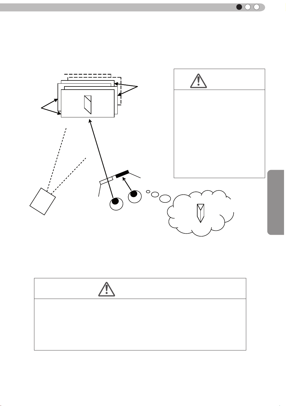
ENGLISH
The frame sequential method is a way of displaying video images left and right sequentially. The projector
projects the video images used for the left- and right eyes onto the screen. The video images for the left
and right side are only visible with the respective eye, as the left and right side of the 3D glasses are
opened and shut by a liquid crystal shutter. As a result, the left and right images are seen by the eye and
show a 3D image.
CAUTION
Left-
eye
image
Right-eye
image
• As the video images for the left
and right side ash alternatively
when displayed, we urge you to
refrain from looking at the screen
with naked eyes. When viewed
with several people, please
prepare glasses for them.
• These 3D glasses are only for the
3D video images of this device.
Please do not use it for watching
other objects or 2D video images.
Close
Open
3D-glasses
Eye
Stereoscopic
video image
Video image projection
with the projector frame
sequential method
In order to match the timing of the display of video images and the timing of the opening/closing of the 3D
glasses liquid crystal shutters and it is necessary to show to the eyes only those video images, for the left
or right eye, respectively, the projector of this unit sends these timing data from the 3D synchro emitter to
the 3D glasses with infrared rays.
Operation
CAUTION
• In regard to the 3D emitter, please direct the 3D glasses in such a way towards it, that
the infrared rays can directly reach the 3D glasses.
• In the following cases, it may not work correctly.
• If you are near infrared communication equipment or lighting equipment.
• If the 3D-glasses do not face to the 3D synchro emitter.
• Depending on the use of 3D emitters, it may be possible that its operation might
inuence the operation of other devices with infrared communication.
77
Page 78

4
Maintenance
Replacing the Lamp
The lamp is a consumable item. If the image is dark or the lamp is turned off, replace the lamp
unit.
● When the lamp replacement time approaches, a message is displayed on the screen and the condition
is indicated by the indicator. (Reference page: 17 to 18, 86)
CAUTION
●
Do not insert your hands into
the opening of the lamp!
This could cause obvious
deterioration of the
equipment’s
and electric shocks.
●
Do not replace the lamp
immediately after the unit has
been used, and allow a cooling
period of 1 hour or more before
replacement. The temperature
of the lamp is still high and this
may cause a burn.
●
Do not apply shock to the
lamp unit. It may cause lamp
blowout.
●
Do not use flammable air duster
to clean the internal parts of the
unit. This may cause fire.
Usable Lamp Life
●
When using the “Lamp Power”
set at “N
the lamp will be approximately
3000 hours.
This is an average lifetime and
cannot be guaranteed.
●
The lamp life may not reach
3000 hours depending on the
operating conditions.
●
When the lamp has reached
the end of its usable life,
deterioration progresses
rapidly.
●
If the picture becomes dark,
the tint becomes strange, or
the image flickers, promptly the
lamp unit for a new one.
function, wounds
MEMO
ormal", the lifetime of
Lamp replacement procedure
Remove the power plug from the
1
outlet
Remove the lamp cover
2
●
Remove the screws with a
Loosen the screws on the lamp unit
3
●
Loosen the screws with a screwdriver.
Pull out the lamp unit
4
●
Grasp the handle and pull out the lamp unit.
screwdriver.
Purchasing the Lamp Unit
Please consult your authorized
dealer.
Lamp Unit
■
Part No.: PK-L2210U
78
Handle
Page 79

Maintenance
ENGLISH
Install the new lamp unit
5
Handle
Tighten the screws of the new lamp
6
unit
●
Tighten the screws with a screwdriver.
CAUTION
●
Use only genuine replacement
parts for the lamp unit. Also,
never attempt to reuse an old
lamp unit. This may cause a
malfunction.
●
Do not touch the surface of a
new lamp. This may shorten
the lamp life and cause lamp
blowout.
MEMO
After Replacing the Lamp
●
Do not place the removed
lamp unit at locations that is
reachable by children or near
combustible items
●
Dispose used lamp units in
the same way as uorescent
lamps. Follow your local
community rules for disposal.
.
Attach the lamp cover
7
●
Insert the top part (with 2 claws) of the lamp cover into
the unit.
●
Fasten the screws with a screwdriver.
79
Page 80

4
Exit
MENU
BACK
Back
Select
Operate
Trigger
Off Timer
Communication Terminal
Network
High Altitude Mode
LAN
Off
Off
Off
Function
Lamp Reset
Remote Code
A
Reset Lamp Time?
YES
NO
7
Maintenance
Replacing the Lamp (Continued)
Resetting lamp Time
STAND BY
HDMI 1
3D
FORMAT
LENS.
CONTROL
HIDE
MENU
FILM
NATURAL
THX
GAMMA
INPUT
HDMI 2
3D
SETTING
LENS
MEMORY
PICTURE MODE
CINEMA
STAGE 3D
USER
COLOR
COLOR
TEMP
P.FILE
ON
COMP
ANAMO.
ANIME
C.M.D.
PC
LIGHT
BACK
ADJ.
After replacing a new lamp unit, please reset the lamp time.
Description of two methods.
.
PIC.
Reset the lamp time from the menu screen.
Display the setting menu
1
Picture Adjust
Picture Mode
Color Profile
Color Temp.
MENU
Select“Function” “Lamp Reset”
2
Gamma
Dark/Bright Level
Picture Tone
Contrast
Brightness
Color
Tint
Advanced
Exit
MENU
① Select
Select
0
0
0
0
Operate
Natural
Video
6500K
Normal
Reset
Back
BACK
80
70
90
X
: The same button
30
arrangement is used for the
operations in this explanation.
Re-conrm
3
● Select
one returns to the previous menu.
② Confirm
“
Yes” and the lamp time is set to zero. Moreover,
Page 81

Maintenance
ENGLISH
7
Reset the lamp time by remote control.
Insert the power plug to the power
1
outlet
Red Lights
Must operate with the remote
2
control in the standby mode (the
projector is powered, but is not
turned on).
●
Press in the order as shown.
●
Press each button within 2-second intervals and press
the last button for 2 seconds or more.
BACK
OK
HIDE
Press for 2 seconds or more
STAND BY
HDMI 1
3D
FORMAT
LENS.
CONTROL
HIDE
MENU
FILM
NATURAL
THX
GAMMA
INPUT
HDMI 2
3D
SETTING
LENS
MEMORY
PICTURE MODE
CINEMA
STAGE 3D
USER
COLOR
COLOR
TEMP
P.FILE
ON
COMP
ANAMO.
ANIME
C.M.D.
PC
LIGHT
BACK
.
PIC.
ADJ.
●
[STANDBY/ON] indicator and [LAMP] indicator blink
alternately for 3 seconds. After that, the unit switches to
standby mode.
70
90
X
: The same button
30
arrangement is used for the
operations in this explanation.
STANDBY/ON
LAMP
WARNING
CAUTION
●
Reset the lamp time only when
you have replaced the lamp.
●
Never reset the service time when
the lamp is still in use. Otherwise,
the approximate standard for
gauging replacement time may be
inaccurate and lamp blowout may
occur.
81
Page 82

4
Maintenance
Method for cleaning and
replacing lters
Clean the filter regularly or air intake efficiency may deteriorate and malfunction may
occur.
Remove the inner lter.
1
Clean the lter.
2
Lift up while pushing the claw
●
Pull the power plug from the
power outlet.
●
Please turn this unit and if
you put in on a bed or a table,
rst place something soft
like a piece of cloth below.
Then you can put it on top of
it. Otherwise, it may cause
scratches on this unit.
CAUTION
●
Wash the lter with water and dry it in a shaded area.
●
In extremely soiled cases, using a neutral detergent
is recommended. Put on rubber gloves when using a
neutral detergent.
●
After washing the lter with water, make sure that it is
completely dry before reinstalling. Otherwise electric
shock or malfunctions may occur.
●
Do not clean the lter with a vacuum cleaner or air
duster. The lter is soft and may be damaged.
Reinstall the inner lter.
3
Check that the left and
right claws are locked onto
the unit
MEMO
If the lter is damaged or
too dirty to be cleaned.
●
Replace with a new lter. A
dirty lter will dirty the internal
parts of the unit and cause
shadows on the video image.
●
To purchase a new lter or
when it is dirty in the internal
parts, consult your authorized
dealer.
Inner Filter
■
Part No.:
●
Replacement Filter:
PC010661199
82
Page 83

Maintenance
MEMO
ENGLISH
83
Page 84

5
Others
Troubleshooting
Before sending the unit to your authorized dealer for repair, please
check the following points.
The following situations are not malfunctions.
■
You do not need to worry about the following situations if there is no abnormality on the
screen.
●
Part of the top surface or front of the unit is hot.
●
A creaking sound is heard from the unit.
●
An operating sound is heard from the inside of the unit.
●
Color smear occurs on some screens.
■
Perform the following operations when the unit is unable to operate normally due to external
static or noise.
① When the unit is in standby mode, please pull out the power plug, then insert again.
② Press the power button on the unit to turn on the power again.
■
A sound may be heard when the lamp is off but there is no danger.
■
D-ILA device is manufactured using high-precision technology but there may be some missing
pixels or pixels that remain permanently lit up.
Power is not supplied
Is the power cord disconnected? Insert the power cord (plug) rmly.
Remove the power plug when the unit is
Is the lamp cover properly shut?
Is the lamp in Cool Down
mode?
in standby mode and close the lamp cover
properly. After that, insert the plug again.
After the Cool Down mode is complete, turn
on the power again.
Reference page:
34
Reference page:
79
Reference page:
37
Video image does not appear
Is the correct external input
selected?
Is the AV device properly
connected?
Is the power of the AV device
turned on?
Are the correct signals being
output from the AV device?
Is the setting of the input
terminal correct?
Is the video image temporarily
hidden?
Select the correct external input.
Connect the AV device properly.
Turn on the power of the AV device and play
the video.
Set the AV device properly.
Set “COMP.” and “HDMI” in the setting menu
according to the input signal.
Press the [HIDE] button to display the video
image again.
Remote control does not work
Are batteries installed
correctly?
Are batteries exhausted? Replace with new batteries.
Is there an obstructive object
between the remote control
and remote sensor?
Is the remote control held too
far away from the unit?
Match the polarities ( or ) correctly when
inserting the batteries.
Remove any obstructive objects.
Hold the remote control closer to the sensor
when using.
Reference page:
36
Reference page:
28 to 33
Reference page:
34
Reference page:
28 to 33
Reference page:
60 to 61
Reference page:
41
Reference page:
21
Reference page:
21
Reference page:
25
Reference page:
25
84
Page 85

ENGLISH
The picture cannot be projected
Will the picture icker and
become invisible with HDMI
input?
Please use a short HDMI cable.
Reference page:
29
The image cannot output by HDMI terminal
Is the setup of “Control with
HDMI” function “Off”?
● Even if the “Control with HDMI” function is “On”, there are still some devices cannot reveal image
normally.
Set up the “Control with HDMI” function to “Off”.
Reference page:
62
Color does not appear or looks strange
Is the image correctly adjusted?
Adjust “Color” and “Tint” in the setting menu.
Reference page:
54
Video image is fuzzy
Is the focus correctly adjusted? Adjust the focus.
Is the unit placed too near or too
far away from the screen?
Set the unit at a correct distance from the
screen.
Reference page:
36
Reference page:
23, 25
Video images are missing
Reference page:
Has setting been performed for
screen mask?
Is the display out of position?
Set “Mask” in the setting menu to “Off”.
Alter the “Picture Position” value in the setting
menu to ensure that images are not missing.
40
Reference page:
61
Reference page:
60
Projected image is dark
Is the lamp near exhaustion?
Check the lamp time on the information menu.
Prepare a new lamp unit or replace as soon
as possible when the lamp is near exhaustion.
Reference page:
78 to 81
The unit works when power is turned on but stops abruptly after a few minutes
Are the air inlets and exhaust
vent blocked?
Is the lter dirty? Clean the lter.
Remove the power plug when the unit is in
standby mode and remove any blocking object.
After that, insert the plug again.
Reference page:
3, 15
Reference page:
82
Power is cut off suddenly
Has setting been performed for
off timer?
Set “Off Timer” in the setting menu to “Off”.
Reference page:
72
Others
85
Page 86

5
COMP.
Others
In case this message is
displayed
Message Cause (Details)
COMP㧚
䇭NO Input
Lamp replacement
Back
BACK
No device is connected to the input terminal.
The input terminal is connected but there is no signal.
Input the video signals.
A video signal that cannot be used in this unit has been input.
Input video signals that can be used.
* The names of input terminals such as COMP. will be displayed in yellow
This message is displayed when the accumulated lamp time has
exceeded 2900 hours.
To clear the message, press the [Back] button.
Get ready a new lamp unit and replace as soon as possible. Reset
the lamp time after replacing the lamp. (Reference page: 78 to 81)
86
Page 87

ENGLISH
RS-232C Interface
It is possible to control this machine, if it is connected by an RS-232C cross cable (D-Sub9
pin) to a PC. Otherwise, this machine can be controlled via a computer network by connecting
it with a LAN cable and sending of control commands. Please use it after you have understood
this by reading professional books, or by discussing it with a system administrator.
RS-232C Specications
This unit
Pin No. Signal Function Signal Direction
2 RxD
Receive data PC→This unit
Mode
Character Length
Parity
Start Bit
Stop Bit
Data rate
Data format
●
3 TxD
5 GND
1,4,6 - 9 N/C - -
PC refers to the controller such as a personal computer.
Non-synchronous
8 bit
None
1
1
19200 bps
Binary
Transmit data This unit→PC
Signal ground
Start Bit
-
D6 D7D4 D5D2 D3D0 D1
Stop Bit
TCP/IP-connection
Before you can control it via LAN, you have to establish a TCP-connection via a "3-way-handshake". It is
necessary for a connection authentication to send from the projector "PJ_OK" and - within 5 seconds after
sending a "PJREQ" – to receive "PJACK". Please perform this operation – after conrming the operating
status of the projector - again after establishment of a TCP connection, if you cannot send within 5 seconds
"PJ_NG" or could not receive "PJNAK".
Within 5 seconds
Projector
PJ_OK
PJACK
TCP-layer connection establishment
TCP port number 20554
Three-way handshake
Control PC
Connection authentication procedure
Others
Projector Control
PJREQ
87
Page 88

5
Others
RS-232C Interface (Continued)
Command Format
The command between this unit and the computer consists of “Header”, “Unit ID”, “Command”, “Data”
and “End”.
●
Header (1 byte), Unit ID (2 bytes), Command (2 bytes), Data (n bytes), End (1 byte)
Header
■
This binary code indicates the start of communication.
Binary code
21 Operating command PC
3F
40 Reference command This unit → PC
06 ACK
Unit ID
■
This code species the unit. The binary code is xed at “8901”.
Command and data
■
Operating command and data (Binary code)
Command Type Description
0000
5057
Response command PC
Connection check
Power supply
Type Description
This unit
→
This unit
→
This unit → PC
(When the command is accepted without error, it
returns to PC)
Check whether communication is available between this
unit and the PC during standby.
During standby
31: Turn on the power.
During power on
30: Turn off the power. (Standby mode)
88
4950
5243
Input
Remote Control
During power on
32: COMP.
33: PC
36: HDMI 1
37: HDMI 2
Sends the same code as the supplied remote control.
●
“Remote control code” (Reference page: 89)
90
70
Page 89

ENGLISH
30
30
30
Reference command and data (Binary code)
Command Type Data description
During standby or power on
30: Standby mode
■
End
5057
4950
Power supply
Input
31: Power-on mode
32: During Cool Down mode
34: Warning mode
During power on
32: COMP.
70
32: PC
36: HDMI 1
37: HDMI 2
90
This code indicates the end of communication. The binary code is xed at “0A”.
■
Remote control code
●
Binary code is sent during communication.
●
The remote control code is "A". Make the head of the code "36" when the remote control code is "B".
Remote control button
name
BACK 37 33 30 33 HDMI 1 37 33 37 30
ON 37 33 30 35 HDMI 2 37 33 37 31
STAND BY 37 33 30 36 PIC.ADJ. 37 33 37 32
HIDE 37 33 31 44 INFO 37 33 37 34
LENS.AP. 37 33 32 30 GAMMA 37 33 37 35
MENU 37 33 32 45 C.TEMP 37 33 37 36
OK 37 33 32 46 3D 37 33 38 37
LENS CONTROL 37 33 33 30 COLOR PROFILE 37 33 38 38
PC
FILM 37 33 36 39
70
90
COMP. 37 33 34 44 LENS MEMORY 37 33 44 34
ANIME 37 33 36 36 3D SETTING 37 33 44 35
STAGE 37 33 36 37 3D FORMAT 37 33 44 36
CINEMA 37 33 36 38 USER 37 33 44 37
Binary code
37 33 30 31 NATURAL 37 33 36 41
37 33 30 32
37 33 33 34 C.M.D 37 33 38 41
37 33 33 36 ANAMO 37 33 43 35
37 33 34 36 COLOR SPACE 37 33 43 44
Remote control button
name
THX
90
70
Binary code
37 33 36 46
Others
89
Page 90

5
Others
RS-232C Interface (Continued)
RS-232C Communication Examples
This section shows the communication examples of RS-232C.
Operating command
■
Type Command Description
Connection
check
Power (On)
Power (Off)
Input
(COMP.)
Remote
Control
(MENU)
■
Reference command
PC→This unit: 21 89 01 00 00 0A
This unit→PC: 06 89 01 00 00 0A
PC→This unit: 21 89 01 50 57 31 0A
This unit→PC: 06 89 01 50 57 0A
PC→This unit: 21 89 01 50 57 30 0A
This unit→PC: 06 89 01 50 57 0A
PC→This unit: 21 89 01 49 50 32 0A
This unit→PC: 06 89 01 49 50 0A
PC→This unit: 21 89 01 52 43 37 33 32 45 0A
This unit→PC: 06 89 01 52 43 0A
Connection check.
When power is turned on from
standby mode.
When power is turned off
(standby mode) from power-on
mode.
When video input is set to
component.
When the same operation as
pressing the [MENU] button
on the remote control is made
Type Command Description
Power (On)
Input
(HDMI 1)
PC→This unit: 3F 89 01 50 57 0A
This unit→PC: 06 89 01 50 57 0A
This unit→PC: 40 89 01 50 57 31 0A
PC→This unit: 3F 89 01 49 50 0A
This unit→PC: 06 89 01 49 50 0A
This unit→PC: 40 89 01 49 50 36 0A
When information of poweron mode is acquired.
When information of HDMI 1
input is acquired.
90
Page 91

Copyright and Caution
About Trademarks and Copyright
●
HDMI, HDMI logo and high denition multimedia interface
are trademarks or registered trademarks of HDMI Licensing
LCC.
Caution
ENGLISH
D-ILA Device Characteristics
Do not project still pictures or pictures that have still
segments for a long period of time. The still parts of
the picture may remain on the screen.
Take special notice of images on the screens of
video games and computer programs. There is no
problem when playing normal video images such as
movies.
When Unit is Unused for a Long Time
Prolonged disuse of the unit may effect an error on the
functions. Turn on the power occasionally and operate
the unit.
Usage Environment
●
Avoid direct exposure of screen to direct sunlight
and illumination. Block light using a curtain.
Images can be well projected by darkening the
brightness of the room.
●
Do not use this unit in rooms with cigarette
smoke or oily smoke. This may cause the unit
to malfunction.
Parts Replacement
Maintenance Procedures
Dirt on the cabinet
●
Gently clean dirt on the cabinet with a soft cloth.
In the case of heavy soiling, soak a cloth in water,
wring dry and wipe, followed by wiping again with
a dry cloth. Pay attention to the following as the
cabinet may deteriorate in condition or paint may
come off.
● Do not wipe with thinner or benzene.
● Do not spray with volatile chemicals like
insecticide.
● Do not allow prolonged contact with rubber or
plastic products.
Dirt in the air inlets
●
Use a vacuum cleaner to suck up the dirt.
Otherwise, use a cloth to wipe off the dirt. If dirt
is allowed to accumulate in the air inlets, the
internal temperature cannot be adjusted and this
may cause a malfunction.
Dirt on the lens
●
Clean the dirt using commercial blowers or
lens cleaning papers for cleaning glasses and
cameras. Do not use uid-type cleaning agents.
This may lead to peeling of the surface coating
lm.
(Reference page: 15)
This unit contains parts (optical part, cooling
fan, etc.) that require replacement to maintain
its functioning. The estimated time for parts
replacement varies greatly depending on the
usage and environment. Please consult your
authorized dealer for replacement.
Others
91
Page 92

5
7
Others
Specifications
Product Name
Model Name
Display Panel/Size
Projection Lens
Light-source Lamp
Screen Size
Projection Distance Approx.
Input compatibility signal
Display resolution
Video Input
Input
terminal.
Input
HDMI
Input
PC
Tr
Output
terminal
Control
terminal
Power Requirements
Power Consumption
Operation Environment
Installation Height
Dimensions
(Width x Height x Depth)
Mass
Accessories
igger terminal
3D synchro
RS-232C terminal 1 system , D-sub 9-pin (male) x1 (External control)
Remote terminal 1 system, stereo mini jack x1 (Remote Control)
LAN terminal 1 system, RJ-45 plug x1
D-ILA
DLA-X90R-B,DLA-X70R-B,DLA-X30-B,DLA-X30-W
D-ILA
" (1920pixels x 1080pixels) x 3 (Total no. of pixels: Approx. 6.22million)
0.7
2.0 x power zoom lens (1.4:1 to 2.8:1)
(Zoom/Focus: Power)
220 W Ultra-high pressure mercury lamp [Part No.:
Average lifespan:
Approx. 60" to 200" (Aspect ratio: 16:9)
(Reference page: 26, 27)
3840 dots x 2160 dots
1920 dots x 1080 dots
1 system, RCA
Y:
1.0Vp-p, 75Ω
Pb/Cb, Pr/Cr:0.7Vp-p, 75Ω
(*) A
lso supports R / G / B Sync on G
2 system, HDMI 19
Compatible with the HDMIv1.4a standard
1 system, D-Sub 15 pin VGA
1 system, Φ3
DC OUT 12V, 0.1A
3D synchro emitter dedicated terminal (1 system, mini DIN 3pin)
AC 11
360W (3.5A
330W (3.2A Max) (Standby mode: 0.8W)
Temperature:
Humidity: 20% to 80% (No condensation)
(Storage Temperature:
Below
About 455mmx179mmx472mm
(Excluding foot, lens, and other protruding parts)
15.4kg
(Reference page: 14)
Projector
device
* 2 *3
3000
1.8m to 12m
pin jack
pin
.5mmDC Power Jack ( )
0V-240V 50/60Hz
Standby mode:
Max) (
5ºC to 35ºC
5000ft (1524 m)
/ 14.9kg
70
90
hours (normal mode)
70
90
30
3
×
compliant
(HDCP
2
×
70
90
0.8W)
-10℃ to 60℃ )
X
30
90
X
30
) * 4
* 5
*
PK-L2210U]
70
1
92
Page 93

ENGLISH
Regarding -W the color of the main body is some kind of white color. Regarding –B, the color of the
* 1
main body is some kind of black.
D-ILA is the abbreviation for Direct drive Image Light Amplier.
* 2
* 3 D-ILA devices are manufactured using extremely high-precision technology. Pixel effectiveness is
99.99%. Only 0.01% or less of the pixels are either missing or would remain permanently lit up.
* 4 HDCP is the abbreviation for High-bandwidth Digital Content Protection system.
The image of HDMI input terminal may not be displayed due to HDCP specication change.
* 5 Ethermet is not supported.
●
Design and specications are subject to change without prior notice.
●
Please note that some of the pictures and illustrations may have been abridged, enlarged or
contextualized in order to aid comprehension. Images may differ from the actual product.
Others
93
Page 94

5
90
70
Dimensions
Others
(Unit: mm)
■
Top Surface
Front
Lens center
■
Bottom Surface
472
5
455
Lens
227.5
178.5
103.5
Φ60
24
290
91
59
■■
Back Surface
110
32
Lamp cover
337
Lens
110
92
Connection terminal section of the
illustration is .
94
Page 95

Index
ENGLISH
3D
Shorthand for "Three-dimensional"
Operation Guide (Glossary) ............... Page 74
Connection by 3D SYNCHRO
terminal ............................................. Page 31
3D format of [2-3] 3D Setting ............. Page 63
Picture Mode of [1] Picture Adjust ...... Page 52
Color Profile of [1] Picture Adjust ....... Page 52
Points of note ................................ Page 4, 75
HDMI
Shorthand for "High-Definition Multimedia
Interface"
Specifications .
Connection method ............................ Page 29
[2-1] HDMI .......................................... Page 61
(Note on length) ................................. Page 29
THX
THX Certification .................................Page 11
Picture Mode of [1] Picture Adjust ...... Page 52
Anamorphic Lens
Anamorphic of [3] Installation ............. Page 64
Color
Color Profile of [1] Picture Adjust ....... Page 52
Color temp. of [1] Picture Adjust......... Page 54
Color of [1] Picture Adjust .................. Page 54
Tint of [1] Picture Adjust .................... Page 54
[1-1] Color temp. ............................... Page 55
Color Space of [1-2] Advanced ......... Page 56
[1-2-2] Custom Gamma..................... Page 58
[1-2-3] Color Management ................ Page 59
Screen Size
Distance Chart ................................... Page 25
Aspect (Video) and aspect
(PC) of [2] Input Signal ....................... Page 60
Zoom of [3-1] Lens Control ............... Page 65
Mask
Mask of [2] Input Signal ..................... Page 61
Screen Menu
Table Menu Structure ......................... Page 42
[1] Picture Adjust ................................ Page 42
[2] Input Signal ................................... Page 45
[3] Installation ..................................... Page 47
.....................................Page 92
[4] Display Setup ............................... Page 48
[5] Function ....................................... Page 48
[6] Information .................................... Page 49
Operating procedure ......................... Page 51
Batteries
Types ................................................ Page 14
How to insert batteries ...................... Page 21
Gamma
Glossary .......................................... Page 74
Gamma of [1] Picture Adjust ............ Page 54
[1-2-2] Custom Gamma ................... Page 58
Spare parts
See "Filters" section
See "Lamp" section
Shift
Shift Amount ....................................... Page 23
Adjustment ......................................... Page 37
Zoom
Magnification ...................................... Page 92
Adjustment ......................................... Page 36
Installation
Angle .................................................. Page 23
Settings .............................................. Page 64
Ceiling Mount ................................. Page 4,24
Caution .............................................. Page 22
Settings Menu
Structure ............................................ Page 52
Menu operating method ..................... Page 51
Projection Distance
Distance Chart ................................... Page 25
Input Signal
Analog video Input Format..................Page 26
3D signal compatibility table............... Page 26
PC signal support table ................. Page 26,27
[6] Information .................................... Page 73
Noise
NR. of [1-2] Advanced ........................ Page 56
Filter
Inlet filter location ............................... Page 15
Replacement Filter Number ............... Page 82
Cleaning and Replacement ................ Page 82
Others
95
Page 96

5
Others
Index (continued)
Message
Indicator (LED) display....................... Page 17
Meaning ............................................. Page 86
Lamp
Replacement Lamp Number .............. Page 78
Recommended use time .................... Page 78
Lamp time of [6] Information .............. Page 73
Replacement ...................................... Page 78
Lamp power of [1-2] Advanced .......... Page 57
Lamp reset of [5] Function ................. Page 72
How to reset the lamp time .......... Page 80, 81
Notes of Caution .................................. Page 4
Remote control
Button placement .............................. Page 20
Instructions ......................................... Page 25
Remote Code ..................................... Page 72
See "Dry battery" section
Lens
[3-1] Lens Control ............................. Page 65
Focus of [3-1] Lens Control ............... Page 65
Zoom of [3-1] Lens Control ............... Page 65
Shift of [3-1] Lens Control .................. Page 65
(Cleaning the lens) ............................. Page 91
96
 Loading...