

Page 1
SUPER PROJECTOR
LOCK UNLOCK
HIDE
EXIT
ZOOM
KEYSTONE
SHUTTER
DIGITAL
ZOOM
SHIFT FOCUS
VIC1 VIC2 VIC3
MENU
ENTER
OPERATE
BACK
LIGHT
T
W
T
W
ON
OFF
RM-MQX1G REMOTE CONTROL UNIT
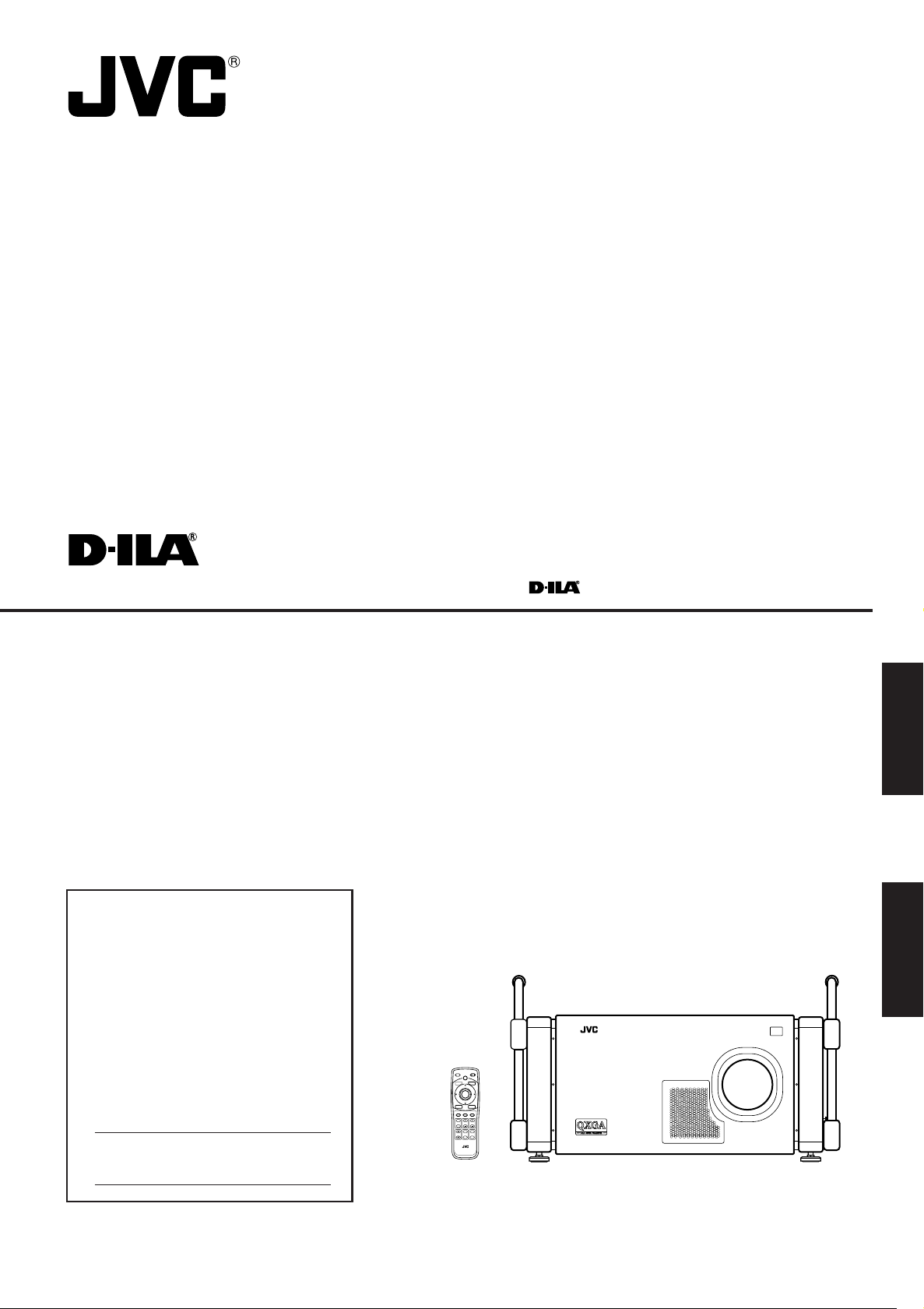
MANUEL D’INSTRUCTIONS : SUPER PROJECTEUR
DLA-QX1G
For Customer Use:
Enter below the Serial No. which is located
on the side panel of the cabinet. Retain this
information for future reference.
INSTRUCTIONS
ENGLISH
Pour l’utilisateur:
FRANÇAIS
Inscrivez ci-dessous le No de série situé sur
le panneau latéral du coffret de l’appareil.
Conservez cette information à titre
d’information.
Model No.
No de modèle DLA-QX1G
Serial No.
No de série
(Lenses are not supplied.)
LCT0963-002A
Page 2

Page 3

INSTRUCTIONS
SUPER PROJECTOR
DLA-QX1G
ENGLISH
Page 4
Thank you for purchasing this projector. Before using it, read and follow all instructions carefully to take full
advantage of the projector’s capabilities.
SAFETY PRECAUTIONS
IMPORTANT INFORMATION
WARNING :
TO PREVENT FIRE OR SHOCK HAZARDS, DO NOT EXPOSE THIS
APPLIANCE TO RAIN OR MOISTURE.
WARNING :
THIS APPARATUS MUST BE EARTHED.
CAUTION :
To reduce the risk of electric shock, do not remove cover. Refer servicing to
qualified service personnel.
MACHINE NOISE INFORMATION
(Germany only)
Changes Machine Noise Information Ordinance 3. GSGV, January 18,
1991: The sound pressure level at the operator position is equal or less
than 70 dB(A) according to ISO 7779.
FCC INFORMATION (U.S.A. only)
CAUTION: Changes or modification not approved by JVC could void the
user’s authority to operate the equipment.
NOTE: This equipment has been tested and found to comply with the limits
for a Class A digital device, pursuant to Part 15 of the FCC Rules. These
limits are designed to provide reasonable protection against harmful
interference when the equipment is operated in a commercial environment.
This equipment generates, uses, and can radiate radio frequency energy
and, if not installed and used in accordance with the instruction manual,
may cause harmful interference to radio communications. Operation of this
equipment in a residential area is likely to cause harmful interference in
which case the user will be required to correct the interference at his own
expense.
About the plug (U.S.A. only)
This projector is equipped with a 3-blade grounding-type plug to satisfy FCC
rule. If you are unable to insert the plug into the outlet, contact your dealer.
About burning-in of the D-ILA device
Do not allow the same still picture to be projected for a long time or an abnormally
bright video picture to be projected.
Do not project video images with high-intensity or high-contrast on a screen. The
video image could be burned in to the D-ILA device.
Use special care when projecting video games or computer program images. There
is no problem with ordinary video-cassette playback images.
2
Page 5

SAFETY PRECAUTIONS (Cont.)
IMPORTANT SAFEGUARDS
Electrical energy can perform many useful functions. This unit has been engineered and manufactured to assure your
personal safety. But IMPROPER USE CAN RESULT IN POTENTIAL ELECTRICAL SHOCK OR FIRE HAZARD. In
order not to defeat the safeguards incorporated into this product, observe the following basic rules for its installation,
use and service. Please read these “IMPORTANT SAFEGUARDS” carefully before use.
– All the safety and operating instructions should be read before the product is operated.
– The safety and operating instructions should be retained for future reference.
– All warnings on the product and in the operating instructions should be adhered to.
– All operating instructions should be followed.
– Unplug this product from the wall outlet before cleaning. Do not use liquid cleaners or aerosol cleaners. Use a damp cloth for
cleaning.
– Do not use attachments not recommended by the product manufacturer as they may be hazardous.
– Do not use this product near water. Do not use immediately after moving from a low temperature to high temperature, as this
causes condensation, which may result in fire, electric shock, or other hazards.
– Do not place this product on an unstable cart, stand, or table. The product may fall, causing serious injury to a child or an adult,
and serious damage to the product. The product should be mounted according to the manufacturer’s instructions, and should
use a mount recommended by the manufacturer.
– When the product is used on a cart, care should be taken to avoid quick stops, excessive force, and uneven
surfaces which may cause the product and cart to overturn, damaging equipment or causing possible injury to
the operator.
– Unplug this product from the wall outlet and refer service to qualified service personnel under the following
conditions:
a) When the power supply cord or plug is damaged.
b) If liquid has been spilled, or objects have fallen on the product.
c) If the product has been exposed to rain or water.
d) If the product does not operate normally by following the operating instructions. Adjust only those controls that are covered
by the Operation Manual, as an improper adjustment of controls may result in damage and will often require extensive
work by a qualified technician to restore the product to normal operation.
e) If the product has been dropped or damaged in any way.
f ) When the product exhibits a distinct change in performance—this indicates a need for service.
– When replacement parts are required, be sure the service technician has used replacement parts specified by the manufacturer
or with same characteristics as the original part. Unauthorized substitutions may result in fire, electric shock, or other hazards.
– Upon completion of any service or repairs to this product, ask the service technician to perform safety checks to determine
that the product is in proper operating condition.
– The product should be placed more than one foot away from heat sources such as radiators, heat registers, stoves, and other
products (including amplifiers) that produce heat.
– When connecting other products such as VCR’s, and personal computers, you should turn off the power of this product for
protection against electric shock.
– Do not place combustibles behind the cooling fan. For example, cloth, paper, matches, aerosol cans or gas lighters that
present special hazards when overheated.
– Do not look into the projection lens while the illumination lamp is turned on. Exposure of your eyes to the strong light can result
in impaired eyesight.
ENGLISH
3
Page 6

SAFETY PRECAUTIONS (Cont.)
– Slots and openings in the cabinet are provided for ventilation. These ensure reliable operation of the product and protect it
from overheating. These openings must not be blocked or covered. (The openings should never be blocked by placing the
product on bed, sofa, rug, or similar surface. It should not be placed in a built-in installation such as a bookcase or rack unless
proper ventilation is provided and the manufacturer’s instructions have been adhered to.)
For proper ventilation, separate the product from other equipment, which may prevent ventilation and keep distance more
than 60 cm (23-5/8”).
– This product should be operated only with the type of power source indicated on the label. If you are not sure of the type of
power supply to your home, consult your product dealer or local power company.
– This product is equipped with a three-wire plug. This plug will fit only into a grounded power outlet. If you are unable to insert
the plug into the outlet, contact your electrician to install the proper outlet. Do not defeat the safety purpose of the grounded
plug.
– Power-supply cords should be routed so that they are not likely to be walked on or pinched by items placed upon or against
them. Pay particular attention to cords at doors, plugs, receptacles, and the point where they exit from the product.
– For added protection of this product during a lightning storm, or when it is left unattended and unused for long periods of time,
unplug it from the wall outlet and disconnect the cable system. This will prevent damage to the product due to lightning and
power line surges.
– Do not overload wall outlets, extension cords, or convenience receptacles on other equipment as this can result in a risk of fire
or electric shock.
– Never push objects of any kind into this product through openings as they may touch dangerous voltage points or short out
parts that could result in a fire or electric shock. Never spill liquid of any kind on the product.
– Do not attempt to service this product yourself as opening or removing covers may expose you to dangerous voltages and
other hazards. Refer all service to qualified service personnel.
– Do not look into the inside of this unit through vents (ventilation holes), etc. Do not look at the light-source lamp directly by
opening the cabinet while the light-source lamp is turned on. The light-source lamp also contains ultraviolet rays and the light
is so powerful that your eyesight can be impaired.
– Xenon gas is enclosed with high pressure inside the light-source lamp (lamp unit) of this projector. If you drop or impart a
shock to the lamp, or discard it as is, there is possibility of explosion, leading to personal injury. Use special care when
handling the lamp. For any unclear points, consult your product dealer.
– Use only the accessory cord designed for this product to prevent shock.
The power supply voltage rating of this product is AC 200 V to 240 V, the power cord attached conforms to the following
power supply voltage. Use only the power cord designated by our dealer to ensure Safety and EMC.
When it is used by other power supply voltage, power cable must be changed.
Consult your product dealer.
* DO NOT allow any unqualified person to install the unit.
Be sure to ask your dealer to install the unit (eg. attaching it to the ceiling) since special technical knowledge and
skills are required for installation.
If installation is performed by an unqualified person, it may cause personal injury or electrical shock.
4
Page 7
SAFETY PRECAUTIONS (Cont.)
POWER CONNECTION
(United Kingdom only)
WARNING
Do not cut off the main plug from this equipment.
If the plug fitted is not suitable for the power points in your home or the cable is too short to reach a power point, then obtain an
appropriate safety approved extension lead or adapter or consult your dealer.
If nonetheless the mains plug is cut off, remove the fuse and dispose of the plug immediately, to avoid a possible shock hazard by
inadvertent connection to the main supply.
If a new main plug has to be fitted, then follow the instruction given below:
WARNING:
THIS APPARATUS MUST BE EARTHED.
IMPORTANT:
The wires in the mains lead on this product are coloured in accordance with the following cord:
Green and Yellow : Earth
Blue : Neutral
Brown : Live
As these colours may not correspond with the coloured making identifying the terminals in your plug, proceed as follows:
The wire which is coloured green-and-yellow must be connected to the terminal which is marked
earth or coloured green or green-and-yellow.
The wire which is coloured blue must be connected to the terminal which is marked with the letter N or coloured black.
The wire which is coloured brown must be connected to the terminal which is marked with the letter L or coloured red.
When replacing the fuse, be sure to use only a correctly rated approved type, re-fit the fuse cover.
IF IN DOUBT —— CONSULT A COMPETENT ELECTRICIAN.
with the letter E or the safety
Information on the power cord plug
The power cord of this projector does not have a wall outlet plug attached. We recomend you to
select and attach a plug which matches your wall outlet.
Use a plug rated 250V/20A.
The wires ends of the power cord are covered for protection. Remove the covers before attaching
the plug to the power cord.
– This equipment is in conformity with the provisions and protection requirements of the corresponding European Directives.
This equipment is designed for professional projector appliances and can be used in the following environments.
• Controlled EMC environment (for example purpose built broadcasting or recording studio), and the rural outdoors environment (far away from railways, transmitters, overhead power lines, etc).
In order to keep the best performance and furthermore for electromagnetic compatibility we recommend to use the cables
not exceeding the following length:
ENGLISH
AC INPUT Power supply cord 3 m
REMOTE Shielded cable 15 m
RGB ANALOG IN Shielded cable 3 m
HDTV ANALOG IN Shielded cable 5 m
RS232C CONTROL IN Shielded cable 3 m
RS232C CONTROL OUT Shielded cable 3 m
HD-SDI IN Shielded cable 5 m
• The inrush current of this apparatus is 17.250 amperes.
5
Page 8

Contents
SAFETY PRECAUTIONS ........................... 2
Accessories ............................................... 7
Controls and Features .............................. 8
Front Side / Top Surface / Right Side .................... 8
Left-hand side / Back Side .................................... 9
Control Panel ...................................................... 10
Connector Panel ................................................. 12
Remote Control Unit ........................................... 14
Cursor (5/ ∞/ 2/ 3) / ENTER
(Menu Operation) Button ............................... 16
Installing Batteries ............................................... 16
Installing the Projector ........................... 17
Precautions for Installation .................................. 17
Adjusting the Inclination of the Projector ............. 19
Installing the Projector against the Screen ......... 20
Projection Distance and Screen Size .................. 21
Lens Shift Function ............................................. 22
Effective Range and
Distance of the Remote Control Unit ............. 24
Connecting to Various Devices .............. 25
Signals that Can Be Input to the Projector .......... 25
Examples of System Configuration ..................... 26
Connecting to RGB Devices ............................... 27
Connecting to Analog HD Devices ...................... 28
Connecting to Digital HD Devices ....................... 29
Connecting to Devices which Control the
Projector......................................................... 30
Connecting the Power Cord (Supplied) .............. 31
Basic Operations..................................... 32
1. Turning On the Power ..................................... 32
■ Turning Off the Power ..................................... 33
2. Selecting the VIC to be Projected ................... 34
3. Adjusting the Screen Size ............................... 35
4. Adjusting Focus ............................................... 35
For Operating Other Functions ........................... 36
■ Turning off the video image (HIDE)................. 36
■ Interrupting the projection light
while video image stops (SHUTTER) .. 36
■ Removing the trapezoidal distortion
of the image (KEYSTONE) .................. 37
■ Setting the amount of lens shifting (SHIFT) .... 38
Menu Operations ..................................... 39
■ No signal menu mode ..................................... 39
■ RGB VIC menu mode ..................................... 40
■ HDTV VIC or HD-SDI VIC menu mode ........... 41
Buttons and Control for the Menu Operation ...... 42
Menu Operation Procedure ................................. 43
Contents of the Menu .......................................... 44
■ Information in Main menu ............................... 44
■ Image adj. menu ............................................. 44
■ Setting menu ................................................... 44
■ VIC menu (VIC menu 1/2) ............................... 45
■ Options menu .................................................. 46
■ Language menu .............................................. 46
■ Color temp. menu ........................................... 46
■ Sub brightness menu ...................................... 46
■ Disp. Posi. menu ............................................. 47
■ Offset & Gain menu ........................................ 47
■ Menu position menu ........................................ 47
■ Keystone menu ............................................... 47
■ User 1 or 2 menu ............................................ 47
■ Lens shift menu ............................................... 47
Cleaning and Replacing the Filters ....... 48
Replacing the Light-Source Lamp ......... 50
Troubleshooting ...................................... 51
Warning Messages.................................. 53
Appendix .................................................. 55
■ Relation between projection distances
and projection screen sizes ................. 55
· GL-MQ1010G ................................................. 55
· GL-MQ1015SG ............................................... 56
· GL-MQ1020ZG ............................................... 57
· GL-MQ1023SZG ............................................. 58
Specifications .......................................... 59
6
Page 9

Accessories
ZOOM
KEYSTONE
SHU
TTER
RM-MQX1G REMOTE CONTROL UNIT
SHIFT
FOCUS
OPERATE
EXIT
MENU
MO
D
E
B
A
CK
LIGH
T
ENTER
VIC1
VIC2
VIC3
T
W
ON
OFF
LOCK
UNLOCK
DIGITAL
ZOO
M
T
W
The following accessories are included with this projector. Check for them; if any item is missing, please contact your
dealer.
(For USA)
(For Europe)
Remote control unit (RM-MQX1G) AA/R6-size dry cell battery (×2)
(for checking operation)
Remote control cable
[approx. 49.2 ft (15 m)]
Protective cap (×8)
(for covering the screw holes)
Power code
[approx. 9.8 ft (3.0 m)]
ENGLISH
Information on separately sold items
• Projection lens
GL-MQ1010G 1 : 1 fixed-focus lens
GL-MQ1015SG 1.5 : 1 fixed-focus lens
GL-MQ1020ZG 2.1 : 1 to 4.9 : 1 zoom lens
GL-MQ1023SZG 3 : 1 to 7 : 1 zoom lens
• Video Interface Card (VIC)
PK-Q01HAG A board to be used for adding HDTV signal (Y, P
function to the projector.
PK-Q01HSDG A board to be used for adding HD-SDI video signal input function to the
projector.
b, and Pr video signal) input
7
Page 10
Controls and Features
Z
O
O
M
F
O
C
U
S
T
W
M
E
N
U
E
N
TE
R
E
X
I
T
V
IC
S
E
L
E
C
T
1
2
3
K
E
Y
S
T
O
N
E
O
P
ER
A
T
E
M
O
D
E
S
T
A
N
D
B
Y
8
2
9
1
1
1
6
5
2
7
1
4
2
R
EMOT
E
C
O
N
TR
O
L
R
S-23
2C
OU
T
RS-2
32C IN
R
G
B
V
H/C
S
RGB
An
alog VIC
3
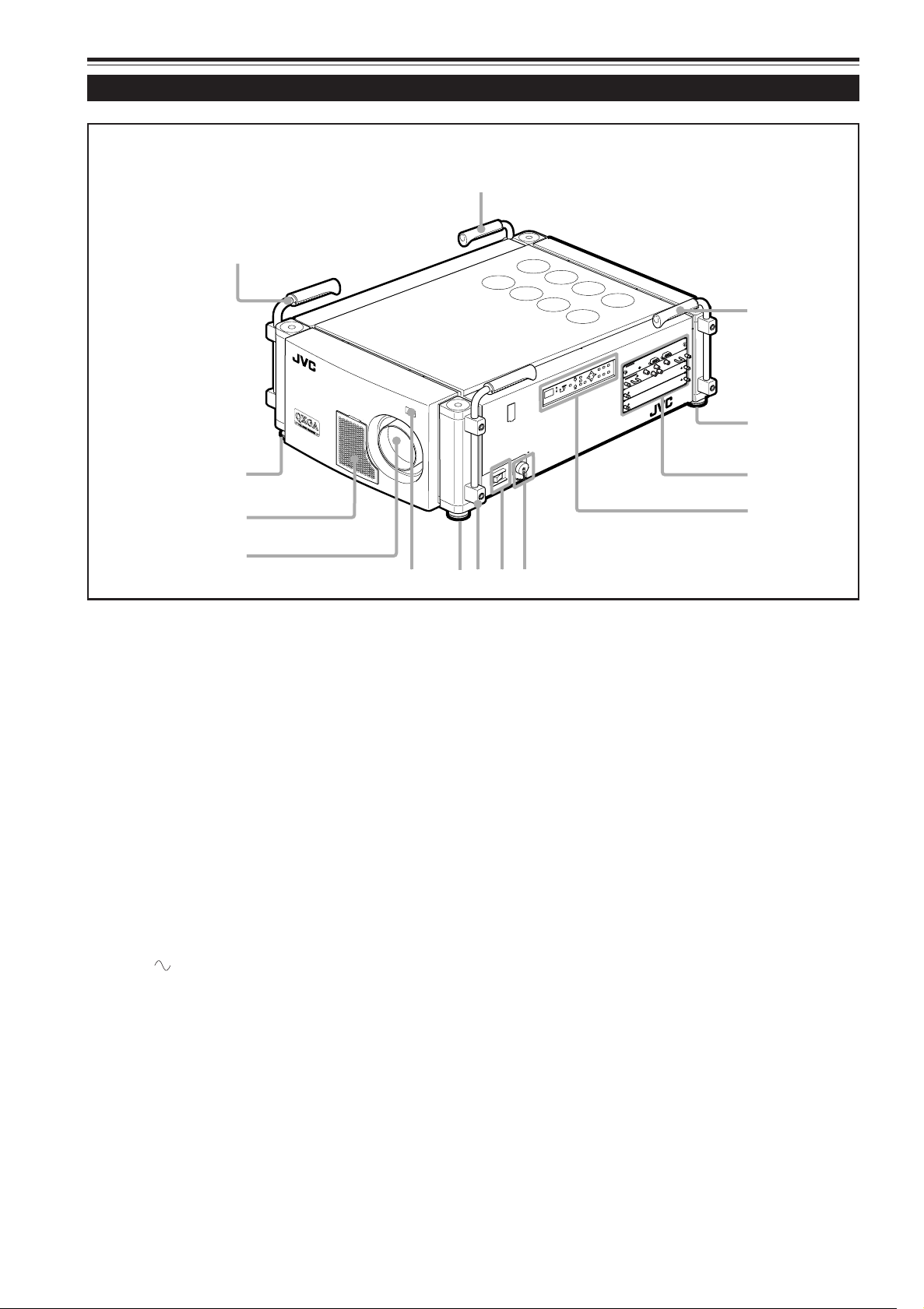
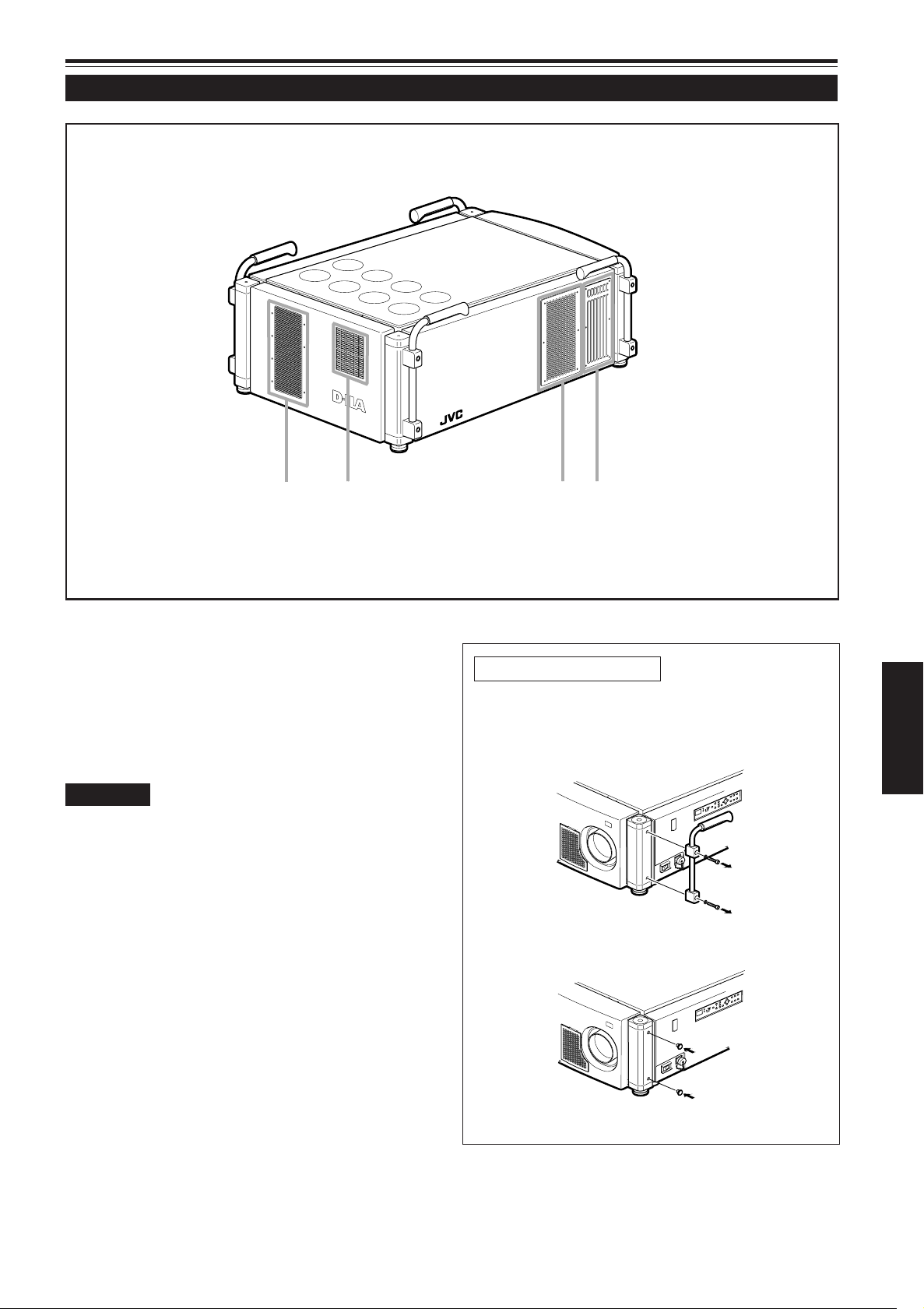
Front Side / Top Surface / Right Side
Handles
1
They are set in place when shipped from the factory. To
carry this projector, use them. You can remove them if
necessary. For details, refer to “To remove the handles”
on page 9.
Adjustable feet
2
They are set at the shortest position when shipped from
the factory. Turn the foot to make the projector level.
Adjustment can be made in the range of ±3.5° vertically
and ±4.5° horizontally.
Connector panel
3
For details, refer to “Connector Panel” on pages 12 and 13.
Control panel
4
For details, refer to “Control Panel” on pages 10 and 11.
AC IN (power input) terminal
5
This is the power input terminal where the supplied power
cord is connected. For details, refer to “Connecting the
Power Cord (Supplied)” on page 31.
MAIN POWER switch
6
This is the main power switch. When it is turned on, the
projector goes into stand-by mode, and the STAND BY
indicator on the control panel comes on.
ON [ ❙ ]: The main power turns on.
OFF [‡]: The main power turns off.
Remote sensor
7
When operating with the remote control unit, aim it at this
sensor. An additional remote sensor is provided on the
control panel of the projector. The effective operating
distance of the remote control is about 32.8 ft (10 m) from
each of the sensors. The effective operating range of angles
is 50° horizontally, and 15° vertically.
Lens mount
8
Attach a projection lens separately sold to this mount.
GL-MQ1010G 1 : 1 fixed-focus lens
GL-MQ1015SG 1.5 : 1 fixed-focus lens
GL-MQ1020ZG 2.1 : 1 to 4.9 : 1 zoom lens
GL-MQ1023SZG 3 : 1 to 7 : 1 zoom lens
For attaching or replacing the lens, consult your dealer
who performed the installation and adjustments of your
projector.
8
Page 11
Controls and Features (cont.)
p
q
e
w
Z
O
O
M
F
O
C
U
S
T
W
M
E
N
U
E
N
T
E
R
E
X
I
T
V
IC
S
E
L
E
C
T
1
2
3
K
E
Y
S
T
O
N
E
O
P
E
R
A
T
E
M
O
D
E
S
T
A
N
D
B
Y
Z
O
O
M
F
O
C
U
S
T
W
M
E
N
U
E
N
T
E
R
E
X
I
T
V
I
C
S
E
L
E
C
T
1
2
3
K
E
Y
S
T
O
N
E
O
P
E
R
A
T
E
M
O
D
E
S
T
A
N
D
B
Y
Left-hand side / Back Side
Intake area (filter)
9, w
Air is taken in through this area to cool the light-source
lamp. If this area is blocked or if something that obstructs
taking-in or exhausted air is placed around the projector,
heat may build up inside and could cause a fire.
For details, refer to “Precautions for Installation” on pages
17 and 18.
CAUTIONS
• Be careful as paper, cloth or soft cushion could be drawn in if placed
nearby. Do not block the intake area, or heat may build up and could
cause a fire.
• Clean the filter periodically. Deposition of dirt on the filter works to
reduce the cooling effect, causing heat to build up inside, which could
cause a fire or malfunction.
For details, refer to “Cleaning and Replacing the Filters” on pages
48 and 49.
Exhaust vent (for the light-source lamp power supply)
e
This vent dischrages warm air from the cooling fan for the
light-source lamp power supply. This fan continues running
as long as the MAIN POWER switch is on.
Exhaust vents
p, q
Vents for cooling fans through which warm air comes out.
To remove the handles
Remove two screws fixing the handle to the projector
with a hex wrench.
• Keep the handles and screws for future use.
ENGLISH
Then, attach the supplied protective caps to cover
the screw holes.
9
Page 12
Controls and Features (cont.)
1234 5678
ZOOM
FOCUS
T
W
+
–
MENU
ENTER
EXIT
VIC SELECT
1
2
3
KEY STONE
OPERATE
HIDE
STAND BY
we9qp
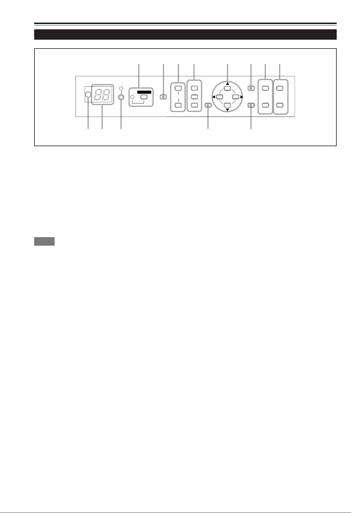
Control Panel
OPERATE indicator
1
ON: When the projector is in operation (projecting)
OPERATE button
Press this button for one or more seconds while the
projector is in stand-by mode, the MAIN POWER switch is
turned on and the OPERATE indicator lights up.
Press it again, and the projector goes into the cool-down
mode, then stand-by mode.
For details on the operations, refer to pages 32 and 33.
Memo
While in the first 20 seconds of cool-down mode:
If you press the OPERATE button, the projector is not tuned on.
HIDE button
2
Use this button to turn off the image on the screen
temporarily. Pressing it again resumes the image.
For details on the operations, refer to page 36.
KEYSTONE buttons
3
Use these buttons to correct a trapezoidal distortion of the
projected image.
For details on the operations, refer to page 37.
VIC SELECT 1, 2, and 3 buttons
4
You can select the desired VIC (Video Input Card) installed
into the projector by pressing one of these buttons.
For details on the operations, refer to page 34.
Cursor (5/∞/2/3) button
5
Use this button in the menu mode to select an item or to
set or adjust the value.
For details on the operations, refer to pages 16 and 42.
MENU button
6
Use this button to enter or exit from the menu mode. The
menu appears or disappears on the screen.
For details on the operations, refer to “Menu Operation
Procedure” page 42.
ZOOM T/W buttons
7
Use these buttons to adjust the projected screen size. (They
work only when the lens unit attached to this projector has
the zooming function.)
T (Tele) : The projected screen size decreases.
W (Wide) : The projected screen size increases.
For details on the operations, refer to page 35.
FOCUS +/– buttons
8
Use these buttons to adjust the focus of the projected video
image.
+ : The focus point becomes more distant.
– : The focus point becomes nearer.
For details on the operations, refer to page 35.
Remote sensor
9
When operating with the remote control unit, aim it at this
sensor. An additional remote sensor is provided on the
control panel of the projector. The effective operating
distance of the remote control is about 32.8 ft (10 m) from
each of the sensors. The effective operating range of angles
is 50° horizontally, and 15° vertically.
Status code display
p
A 2-digit number appears here to show the status of this
projector. Refer to the right.
10
Page 13
Controls and Features (cont.)
1234 5678
ZOOM
FOCUS
T
W
+
–
MENU
ENTER
EXIT
VIC SELECT
1
2
3
KEY STONE
OPERATE
HIDE
STAND BY
we9qp
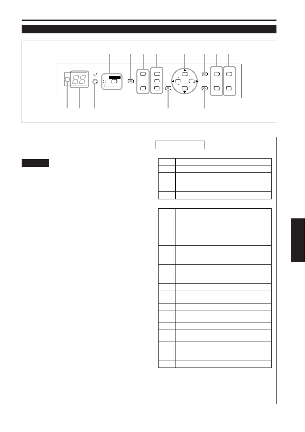
Control Panel (Cont.)
STAND BY Indicator
q
On : When in stand-by mode.
Blinking : While in cool-down mode.
CAUTIONS
• The cool-down mode continues for about 10 minutes. At the first 20
seconds of the cool-down mode, the projection cannot be started
again. During this period, the STAND BY indicator is blinking and
“07” appear on the status code display.
Then, “07” changes into “06” on the status code display, but the
STAND BY indicator is still blinking, and the cooling fans will continue
to run for about 10 minutes before they stop.
After the cooling-down mode, the projector goes into stand-by mode
automatically (the STAND BY indicator is not blinking but lit).
• The purpose of the cool-down mode is to prevent inner parts from
being deformed or broken by heat from the heated lamp as well as
to prolong the life of the lamp.
Do not turn off the MAIN POWER switch while in the cool-down
mode. Also, do not block any of exhaust openings while in cooldown mode.
• The cooling fan for the light-source lamp power supply continues
running as long as the MAIN POWER switch is turned on.
EXIT button
w
Use this button in the menu mode to return to the previous
menu. When the main menu is displayed, this button will
cause the menu to disappear.
For details on the operations, refer to page 42.
ENTER button
e
Use this button in the menu mode. Use it to display the
hierarchical menus. Also use it when “ENTER” is displayed
for the item on the menu.
For details on the operations, refer to pages 16 and 42.
About status code
Normal indications
Code Status
00 The projector is in stand-by mode.
01 The projector is in normal status.
06 The projector is in the cool-down mode.
(enable to start the projection again)
07 The projector is in the cool-down mode.
Error indications
Code Status
02 The side panel is unstable.
Abnormal temperature in the lamp unit.
The lamp cannot light up.
03 The internal shutter is closed or there may
be trouble in the shutter function.
04 The projector is turned off while no signal is
input.
10 The lamp goes off during projection.
20 Trouble in the light-source lamp power
supply.
21 Trouble in the power supply of the projector.
22 Trouble in the power supply of the fan.
23 Trouble in cooling process of R-device.
24 Trouble in cooling process of G-device.
25 Trouble in cooling process of B-device.
30 Trouble in the fan or the sensor of air
pressure.
40 Trouble in the micro processor.
80 The lamp life is near its end (exceed 900
hours).
81 The lamp life is near its end (exceed 1000
hours).
82 Abnormal temperature in the projector.
83 Abnormal temperature in the room.
ENGLISH
11
Page 14
Controls and Features (cont.)
REMOTE
CONTROL
RS-232C OUT
RS-232C IN
2
1
3
B
G
R
V
H/C
S
RGB Analog VIC
4
5
6
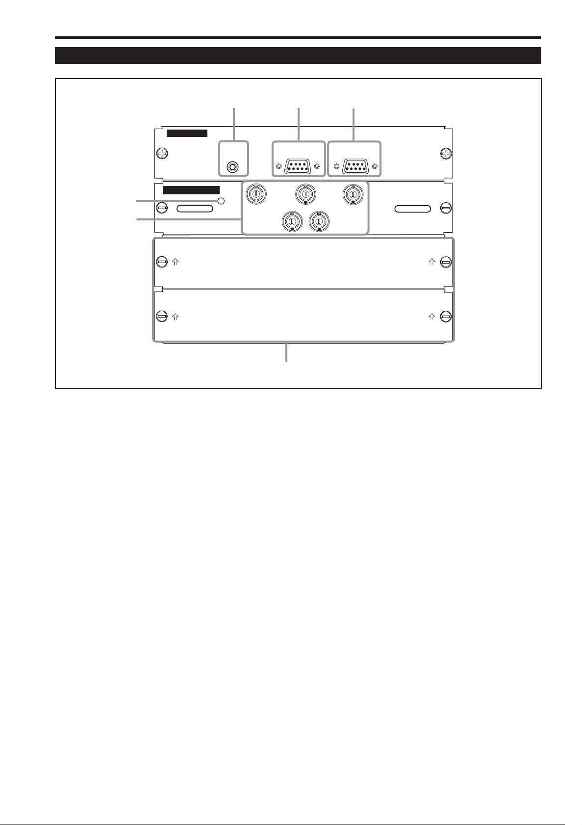
Connector Panel
REMOTE terminal (mini jack)
1
This terminal is used to directly connect the remote control unit to the projector. Use the remote control cable supplied.
RS-232C OUT terminal (D-sub 9 pin)
2
This is an RS-232C interface-specified terminal. When
another DLA-QX1G is connected to this projector using
this terminal, you can enable a computer to control plural
DLA-QX1Gs at the same time.
For details, consult your dealer.
RS-232C IN terminal (D-sub 9 pin)
3
This is a RS-232C interface-specified terminal. This
projector can be controlled by a computer connected
externally.
For details, consult your dealer.
LED
4
This LED lights up when the RGB Analog VIC is selected.
RGB IN terminals (BNC x 5)
5
These are multipurpose video input terminals that allow
input of the following signals.
• Analog RGB signals, vertical sync (V) signals, and
horizontal sync (H) signals / composite signals (Cs).
(Devices which have analog RGB signal output terminals
can be connected.)
* Input of external sync signals is automatically detected.
Detection of H/V signals or Cs signals causes automatic
switching to external sync. The priority order is H/V >
Cs.
• The uppermost edge of the image may appear to bow if
the sync signal input is composite sync (Cs) or G on sync
signal. In this case, use separate sync signals for vertical
sync (V) and horizontal sync (H).
VIC slots (x 2)
6
You can install the optional VICs in this projector using
these slots. The following VICs are available.
• HDTV Analog VIC
This VIC enables the projector to be input the conventional
HDTV signal (Y, P
• HD-SDI VIC
This VIC enables the projector to be input and output the
HD-SDI signal. The output terminal can be used as a line
through terminal for checking the input signal by
connecting the HD-SDI monitor or for using plural
projectors at the same time.
For details, refer to page 13.
b, and Pr).
12
Page 15
Connector Panel (Cont.)
HD-SDI VIC
IN
OUT
Å
ı
HDTV Analog VIC
Y
P
b
P
r
ı
Å
REMOTE
C
O
NT
R
O
L
RS-232C OUT
RS
-232C IN
R
G
B
Y
H/C
S
RGB Analog VIC
R
E
M
O
T
E
CONTROL
RS
-232
C
O
U
T
R
S-232C
IN
R
G
B
Y
H/C
S
RGB Analog VIC
R
G
B
Y
H/C
S
RGB Analog VIC
H
D
TV
A
nalog VIC
Y
P
b
P
r
REMOTE
CONTROL
RS-232C OUT
RS-232C IN
R
G
B
Y
H/C
S
R
GB
Analog V
IC
HDTV Analog VIC
Y
P
b
P
r
About the optional VICs
HDTV Analog VIC
LED
Å
This LED lights up when the HDTV Analog VIC is
selected.
Y, P b, Pr input terminal (BNC x 3)
ı
These are Y, Pb, Pr input terminals for HD signal
(SMPTE260M/274M/296M).
HD-SDI VIC
LED
Å
This LED lights up when the HD-SDI VIC is se-
lected.
SDI input/output (through) terminal (BNC x 2)
ı
These are input and output terminals for HD-SDI
signal (SMPTE292M).
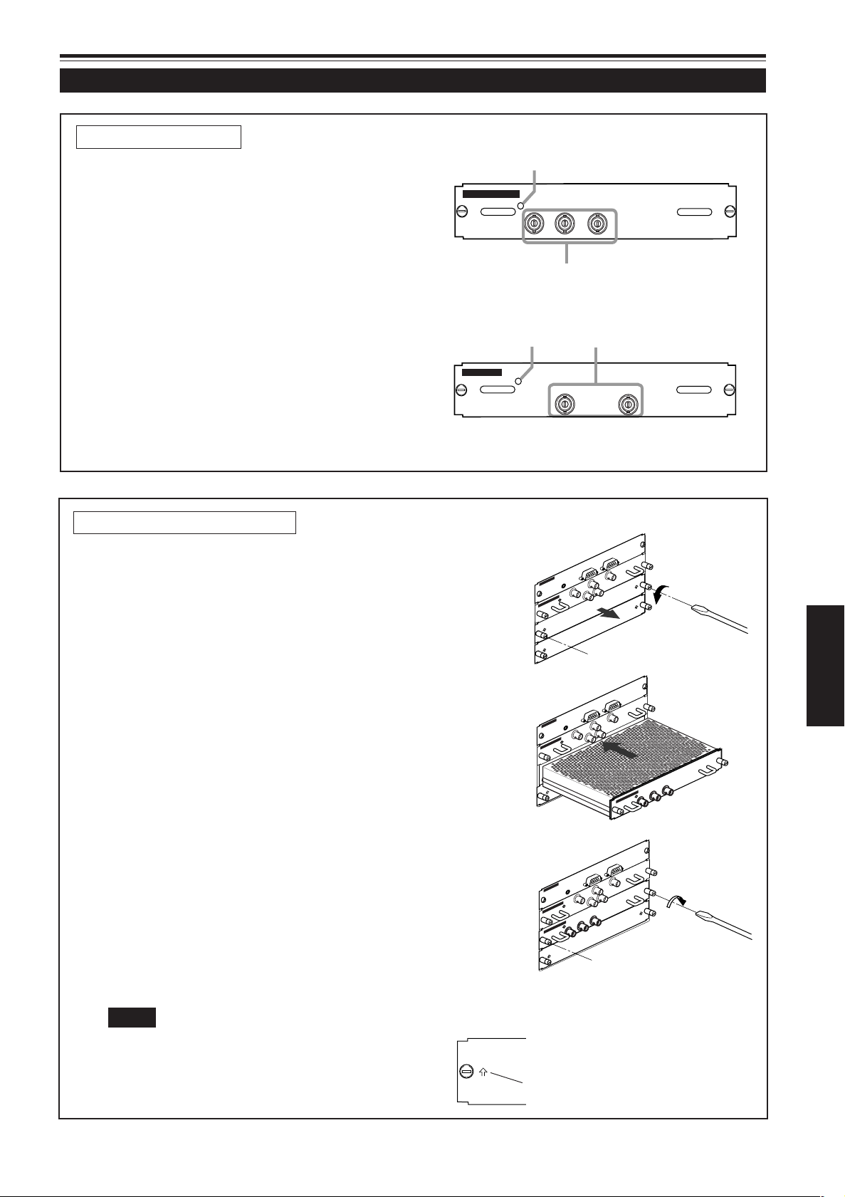
How to install the optional VICs
1
Remove the slot panel from the slot of the
projector.
1) Remove two screws on the slot panel, one on each end,
from an empty slot.
2) Take off the slot panel.
2
Install the VIC.
1) Aligning both ends of the PC board of the VIC with the
grooves inside the slot, insert the VIC into the slot.
2) Push the VIC fully so that two connectors on inner surface
of the VIC are securely plugged into the sockets inside the
slot.
3
Fasten the VIC to the projector.
After inserting the VIC into the slot, fasten it to the projector
with two screws attached to the VIC.
ENGLISH
Notes
• To avoid penetrating of the dust, do not remove the slot
panel from the unused VIC slot.
• When replacing the slot panel, set it with the arrow up
(indicated on the both ends of the slot panel) as shown:
arrow
13
Page 16
Controls and Features (Cont.)
t
RM-MQX1G REMOTE CONTROL UNIT
STON
O
EX
N
LOCK UNLOCK
p
r
w
6
5
4
3
2
1
7
8
q
e
MODE
EXIT
ZOOM
KEYSTONE
SHUTTER
DIGITAL
ZOOM
SHIFT FOCUS
VIC1 VIC2 VIC3
MENU
ENTER
OPERATE
BACK
LIGHT
T
W
T
W
ON
OFF
9
y
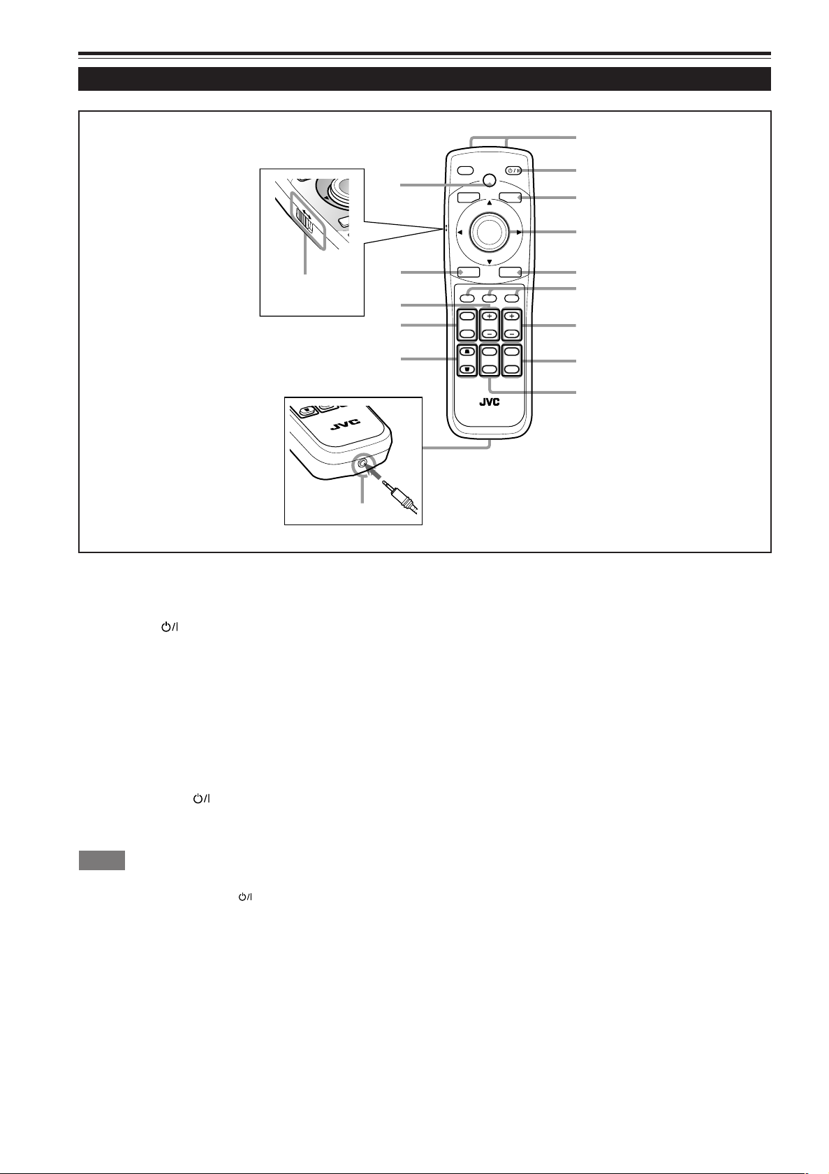
Remote Control Unit
LOCK
KEY
E
UNLOCK
RM-MQX1G REMOTE CONTROL UNIT
Remote control’s signal transmitter
1
Cursor (5/∞/2/3) / ENTER button
4
When using this as the cursor button, press it in the
OPERATE button
2
When the projector is in stand-by mode, press this button
for one second or more to turn on the projector.
The OPERATE indicator lights up.
• About 30 seconds after the power has turned on, video
image will appear on the screen.
When the projector is turned on, press this button for one
5/∞/2/3 directions to select menu items or adjust settings.
When using it as the ENTER button, press the button
straight down.
The ENTER button is used in the menu mode. Use it to
display the hierarchical menus. Also use it when “ENTER”
is displayed for the item on the menu.
For details on the operation, refer to pages 16 and 42.
second or more so that the projector goes into cool-down
mode before going to stand-by mode.
For details, refer to “CAUTIONS” on page 11.
• The OPERATE
1 minute after the light-source lamp is turned on. Use the
button approximately 1 minute later.
Memo
While in cool-down mode (the STAND BY indicator is blinking):
Even if you press the OPERATE button, the projector is not turned
on. Wait until the projector enters stand-by mode. (The STAND BY
indicator stays lit.)
BACK LIGHT button
3
When this button is pressed, all the buttons light up.
When no button is pressed while the buttons are lit, they
will be turned off after several seconds.
button will not work for approximately
MENU button
5
Use this button to enter or exit from the menu mode. The
menu appears or disappears on the screen.
For details on the operation, refer to page 42.
VIC 1, 2, and 3 buttons
6
You can select the desired VIC (Video Input Card) installed
into the projector by pressing one of these buttons.
For details on the operations, refer to page 34.
FOCUS +/– buttons
7
Use these buttons to adjust the focus of the projected video
image.
+: The focus point becomes more distant.
–: The focus point becomes nearer.
For details on the operation, refer to page 35.
DIGITAL ZOOM T/W buttons
Memo
8
Not in use.
14
Page 17
Controls and Features (Cont.)
t
RM-MQX1G REMOTE CONTROL UNIT
STON
O
EX
N
LOCK UNLOCK
p
r
w
6
5
4
3
2
1
7
8
q
e
MODE
EXIT
ZOOM
KEYSTONE
SHUTTER
DIGITAL
ZOOM
SHIFT FOCUS
VIC1 VIC2 VIC3
MENU
ENTER
OPERATE
BACK
LIGHT
T
W
T
W
ON
OFF
9
y
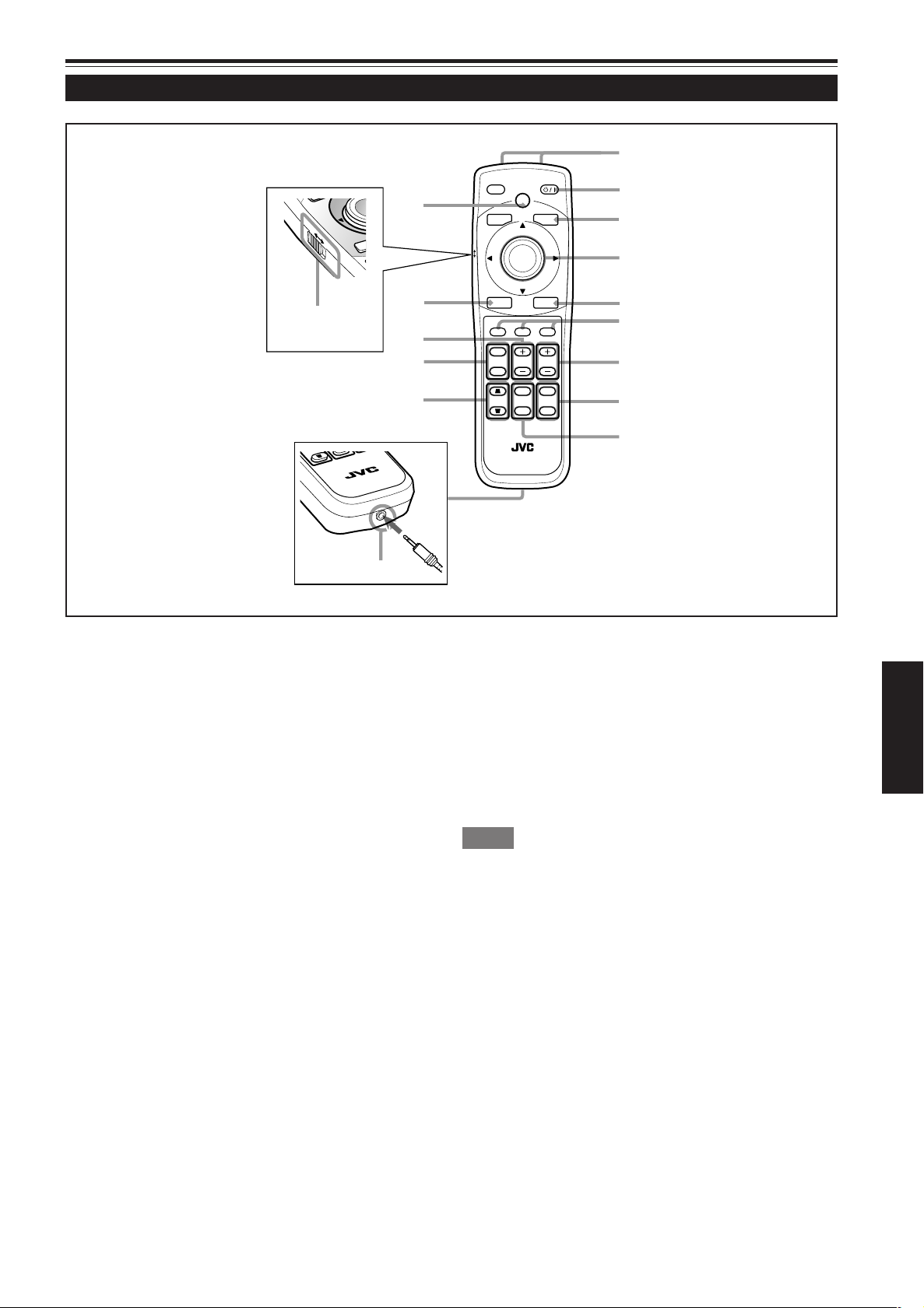
Remote Control Unit (Cont.)
LOCK
KEY
E
UNLOCK
RM-MQX1G REMOTE CONTROL UNIT
SHUTTER ON/OFF buttons
9
Use these buttons to control the internal shutter.
ON : Closes the shutter to turn off the projection.
OFF : Opens the shutter to turn on the projection.
For details on the operation, refer to page 36.
Wired remote control terminal
p
To use the remote control unit as a wired unit, connect the
SHIFT +/– buttons
e
Use these buttons to adjust the height of the projection
screen when projectors are used in a stack configuration*.
(They work only when the lens unit attached to this projector
has the lens shift function.)
+:Moves the screen upwards.
– : Moves the screen downwards.
For details on the operation, refer to page 38.
ENGLISH
supplied remote control cable between this terminal and
the REMOTE terminal on the connector panel of the projector.
For details, refer to page 24.
• The signal transmitter of the remote control unit will stop
working when the cable is connected to this terminal.
KEYSTONE buttons
q
Use these buttons to correct a trapezoidal distortion of the
projected image.
For details on the operation, refer to page 37.
ZOOM T/W buttons
w
Use these buttons to adjust the projected screen size. (They
work only when the lens unit attached to this projector has
the zooming function.)
T (Tele) : The projected screen size decreases.
W (Wide) : The projected screen size increases.
For details on the operations, refer to page 35.
Memo
* Stack configuration:
Up to three projectors can be stacked and used together (stack
configuration). This allows you to project sufficiently bright image in
a fairly large auditorium or relatively bright place.
For details, refer to page 20.
EXIT button
r
Use this button to return to the previous screen when you
are operating the menu.
For details on the operation, refer to page 43.
LOCK Ô UNLOCK switch
t
When this switch is set to “LOCK,” the ZOOM T/W buttons, the SHIFT +/– buttons, and the FOCUS +/– buttons
do not work. When the adjustment is needed, set the switch
to “UNLOCK.”
HIDE button
y
Use this button to turn off the video image temporarily.
Pressing it again makes the video image to resume.
For details on the operation, refer to page 36.
15
Page 18
Controls and Features (cont.)
OPERATE
EXIT
MENU
MODE
BACK
LIGHT
ENTER
VIC3
LOCK
UNLOCK
2
2
2
2
1
Cursor (5/∞/2/3) / ENTER (Menu Operation) Button
The remote control unit supplied for this projector has only one button to navigate through the menus. Pressing the menu
operation button too strongly may cause an incorrect operation. So, before you use the button in an actual situation, have some
practice to make yourself familiar with using the button.
1 When using the Cursor (5/∞/2/3) / ENTER button
as the ENTER button :
Press the button straight down when the menu is displayed. When
pressing the button causes the submenu to be displayed.
appears on the selected item,
2 When using the Cursor (5/∞/2/3) / ENTER button
as a cursor moving button:
Press the button toward one of the 5/∞/2/3. While the
menu is displayed, use the button to select an item to
adjust or make adjustment.
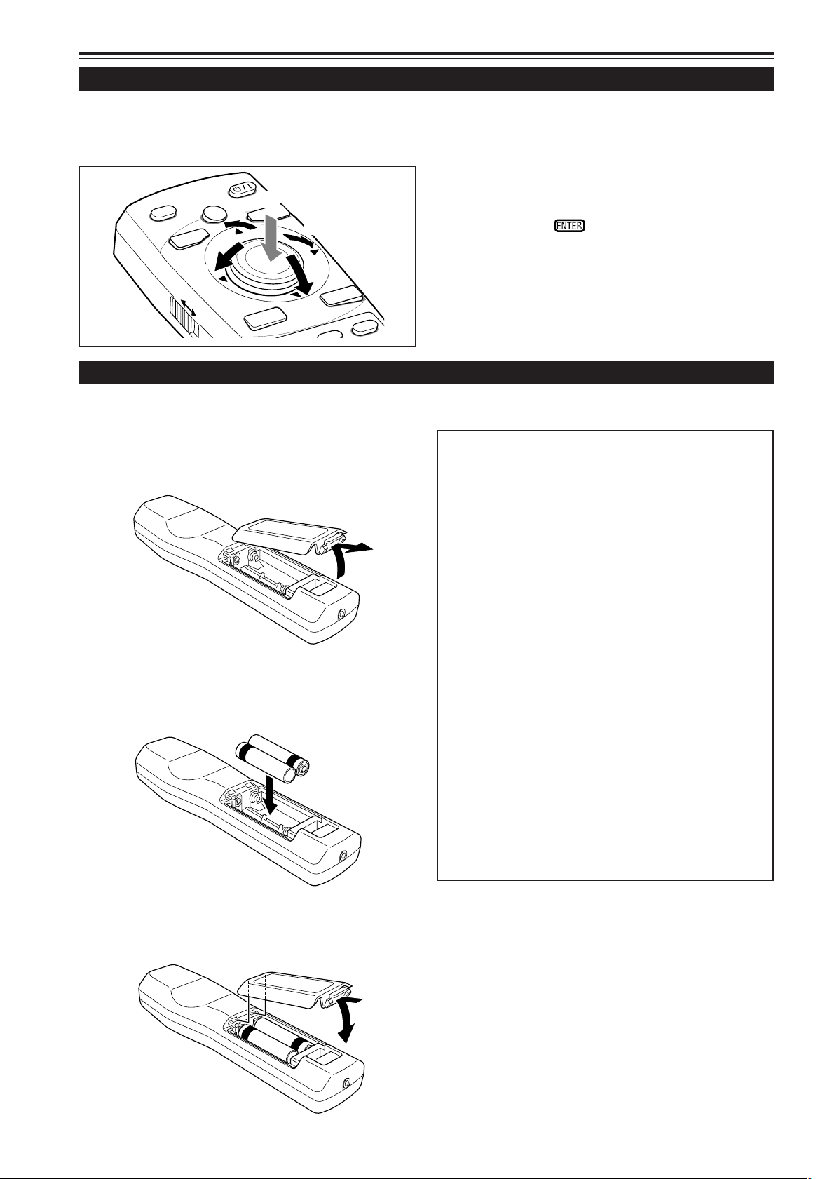
Installing Batteries
Install batteries in the remote control unit. If the remote control has started to work erratically, replace the batteries.
Open the back cover.
1
Open the back cover in the direction of the arrow.
Install the batteries.
2
Place the two batteries (AA/R6-size) supplied in the remote
control unit as illustrated below.
·
ª
ª
·
Precautions for using batteries
If batteries are used incorrectly, they may crack or leak
liquid. This could cause a fire, burn, malfunction, or
staining or damaging the surrounding.
Beware of the following:
• Do not mix new and old batteries.
• Do not mix different types of batteries as they differ in
characteristics.
• Place batteries so they match the polarities indicated:
(+) to (+) and (–) to (–).
• Be sure to put the minus (–) end in first to avoid shortcircuiting.
• Use only designated batteries.
• Remove the batteries if not used for a prolonged period
of time.
• When the batteries are exhausted, replace them
immediately. Otherwise, liquid could leak, or malfunction
could occur due to leaked liquids. If the leaked liquid
contacts the skin, wipe it off with a cloth, otherwise the
skin could become rough.
• Do not put batteries into fire or try to recharge them.
• Batteries run for six months to one year in normal use.
But the batteries supplied are for confirming operation
and may not run that long. When the remote control unit
starts failing to work properly, replace the batteries with
new ones.
Close the back cover.
3
First fit the claw on the back cover into the case, then
close the back cover in the direction of the arrow.
16
Page 19
Installing the Projector
ZOOM
FOCUS
T
W
MENU
ENTER
EXIT
VIC SELECT
1
23KEY STONE
OPERATE
HIDE
STAND BY
REMOTE
CONTROL
RS-232C OUT
RS-232C IN
R
G
B
Y
H/C
S
RGB Analog VIC
Precautions for Installation
CAUTIONS
• Since the projector weighs approx. 92 kg (203 lbs.), be sure to have four or more people when
lifting or moving it; otherwise, the projector could possibly drop, causing personal injury and/or
damage to the projector.
• Do not install the projector in the following places:
• There is much water, humidity or dust.
• The projector may be subjected to oil smoke or cigarette smoke.
• On a soft surface such as a carpet or cushion.
• The projector may be subjected to direct sunlight.
• Temperature is high or humidity is low.
Allowable operation temperature range: + 5°C to + 35°C (41°F to 95°F)
Allowable relative humidity range: 20% to 80% (no condensation)
Allowable storage temperature range: –10°C to +60°C (14°F to 140°F)
■ When installing the projector, observe the following:
• Do not use the projector placed on its side or upside down.
The projector cannot be used by being placed on its side or upside down; otherwise, it could malfunction.
• Use the projector within the range of allowable installation angle.
Avoid using the projector inclined over 5° right-to-left or left-to-right, over 25° front-to-rear or rear-to-front; otherwise it could
cause color variation or harm the lamp life.
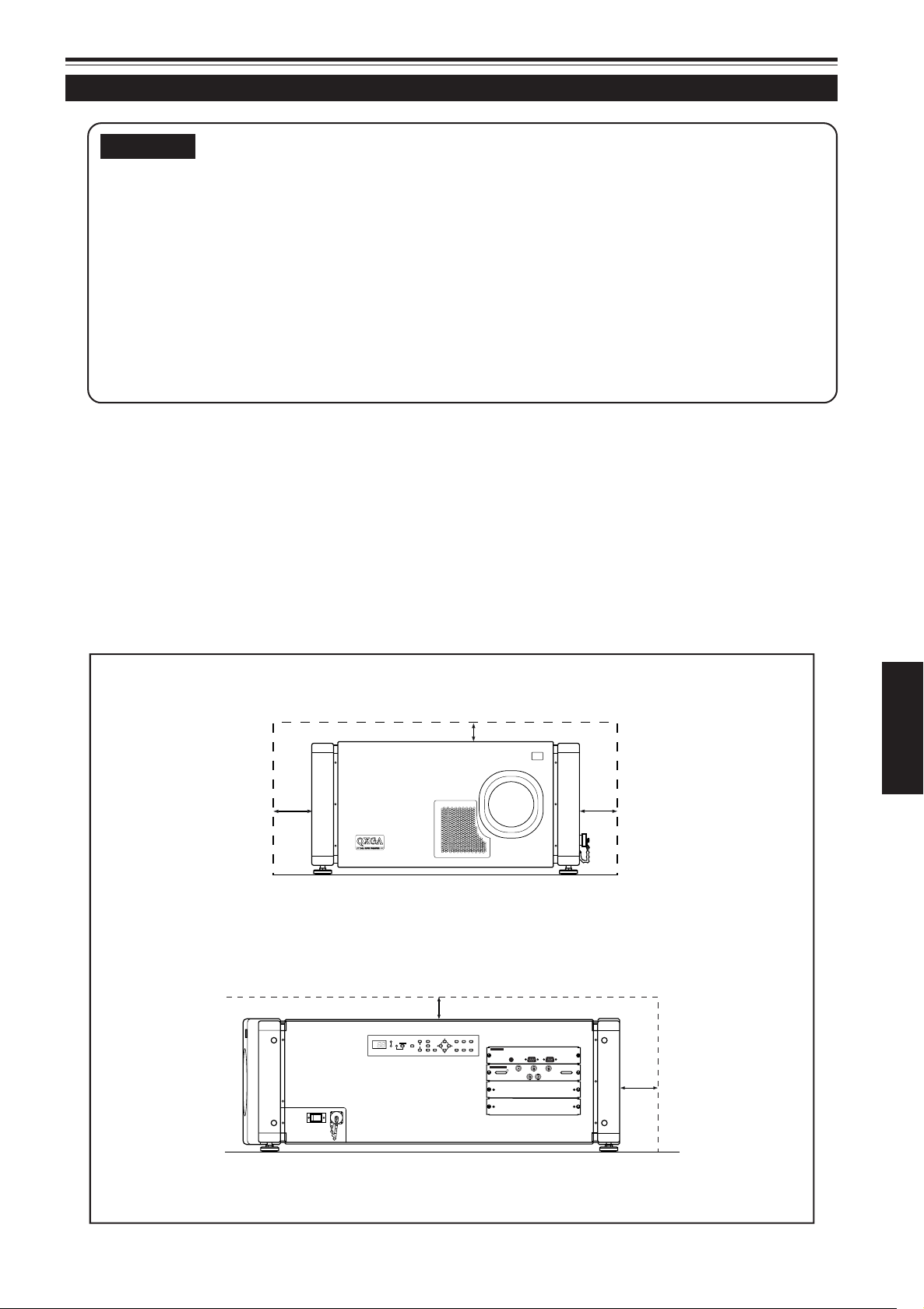
• Do not block the exhaust vents.
Do not use a cover which encloses the projector intake or blocks the exhaust vents. Allow sufficient space around the
projector. When the projector is enclosed in a space of the following dimensions, use an air conditioner so the temperature
inside becomes equal to the outside temperature.
Allowable minimum space required
Front view
600 mm (23-5/8”)
Right side view
305 mm (12”)
ENGLISH
600 mm (23-5/8”)
305 mm (12”)
600 mm (23-5/8”)
17
Page 20
Installing the Projector (Cont.)
ZOOM
FOCUS
T
W
MENU
ENTER
EXIT
VIC SELECT
1
23KEY STONE
OPERATE
HIDE
STAND BY
REMOTE
CONTROL
RS-232C OUT
RS-232C IN
R
G
B
Y
H/C
S
RGB Analog VIC
Precautions for Installation (Cont.)
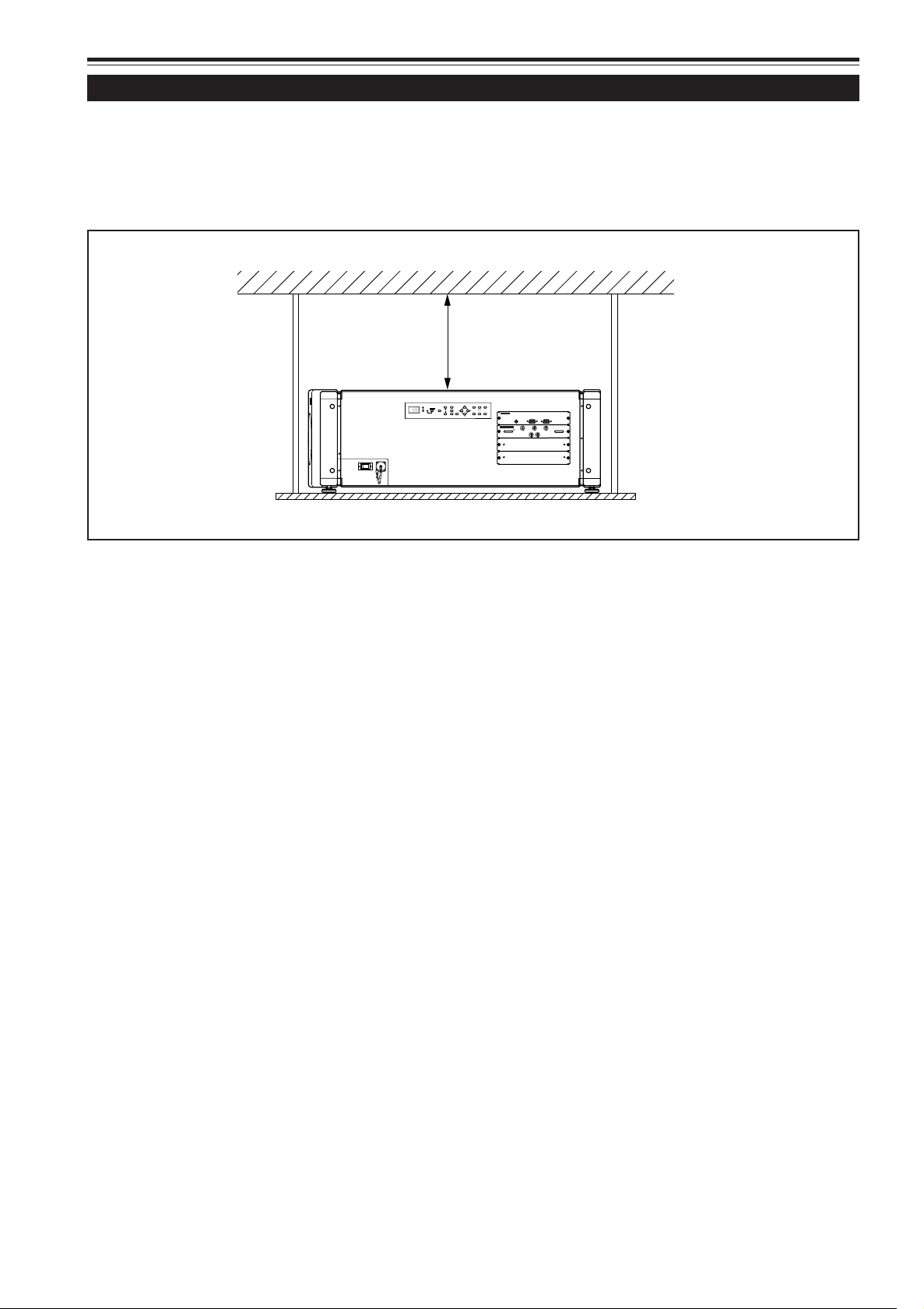
■ Observe the following when hanging the projector from the ceiling
• To prevent falling or overturning, it is recommended that the projector be fixed to its stand with bolts.
• When mounting the projector to the ceiling, first install a special shelf and then place the projector on it securely. For safety
and maintenance purposes, a suitable facility is necessary to easily lift and lower the projector from the shelf for maintenance.
305 mm (12”)
or more
18
Page 21
+3.5
Extend Shorten
+4.5˚
–4.5˚
Extend Shorten
Installing the Projector (Cont.)
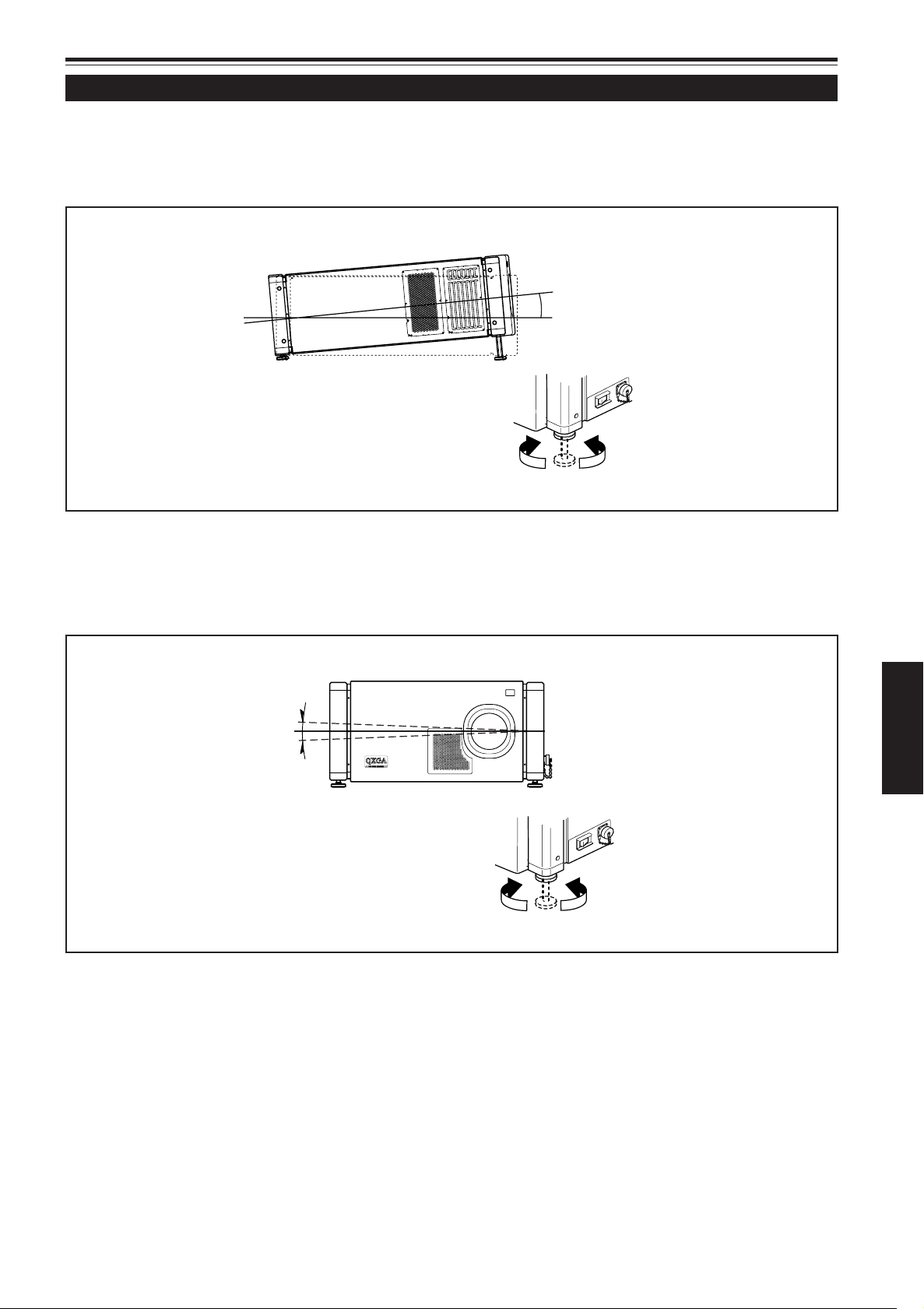
Adjusting the Inclination of the Projector
The vertical angle and the leveling of the projector can be adjusted with the adjustable feet on the bottom of the projector.
■ Adjusting the vertical angle of the projector
Lift the projector, rotate the front adjustable feet, and adjust the vertical angle within the range of 0° to 3.5°.
■ Leveling the projector
Lift the projector, rotate the adjustable feet, and adjust the horizontal angle until the projector is level.
ENGLISH
19
Page 22
Z
O
OM
F
OC
U
S
T
W
M
E
NU
E
N
TE
R
EX
IT
V
IC S
ELE
C
T
1
2
3
KE
Y
ST
O
NE
O
P
E
RA
TE
H
I
D
E
ST
A
ND
BY
RE
M
O
T
E
C
O
N
T
R
O
L
R
S-
2
3
2
C
O
U
T
R
S
-2
3
2
C
I
N
R
G
B
Y
H/C
S
RGB Analog VIC
3.55°
Z
O
O
M
F
O
C
U
S
T
W
M
E
N
U
E
N
T
E
R
E
X
I
T
V
IC
S
E
L
E
C
T
1
2
3
K
E
Y
S
T
O
N
E
O
P
E
R
A
T
E
H
I
D
E
S
T
A
N
D
B
Y
RE
M
O
TE
CO
N
T
R
O
L
R
S
-
2
3
2
C
O
U
T
R
S
-
2
3
2
C
I
N
R
G
B
Y
H
/
C
S
R
G
B
A
na
lo
g
V
IC
Z
OO
M
F
O
C
US
T
W
M
E
N
U
EN
T
E
R
E
X
IT
V
I
C
S
E
L
E
C
T
1
2
3
K
E
Y S
TO
N
E
O
P
E
RA
TE
HI
D
E
ST
A
N
D
B
Y
R
E
MO
TE
C
O
N
T
R
O
L
R
S
-2
3
2
C
O
U
T
R
S
-2
3
2
C
IN
R
G
B
Y
H/C
S
RGB Analog VIC
Z
O
O
M
F
O
C
U
S
T
W
M
E
N
U
E
N
T
E
R
E
X
I
T
V
IC
S
E
L
E
C
T
1
2
3
K
E
Y
S
T
O
N
E
O
P
E
R
A
T
E
H
ID
E
S
T
A
N
D
B
Y
R
E
M
O
T
E
C
O
N
T
R
O
L
R
S
-
2
3
2
C
O
U
T
R
S
-
2
3
2
C
I
N
R
G
B
Y
H/C
S
RGB Analog VIC
Z
O
O
M
F
O
C
U
S
T
W
M
E
N
U
E
N
T
E
R
E
X
I
T
V
I
C
S
E
L
E
C
T
1
2
3
K
E
Y
S
T
O
N
E
O
P
E
R
A
T
E
H
ID
E
S
T
A
N
D
B
Y
R
E
M
O
TE
C
O
N
T
R
O
L
R
S
-
2
3
2
C
O
U
T
R
S
-
2
3
2
C
I
N
R
G
B
Y
H/C
S
RGB Analog VIC
Installing the Projector (Cont.)
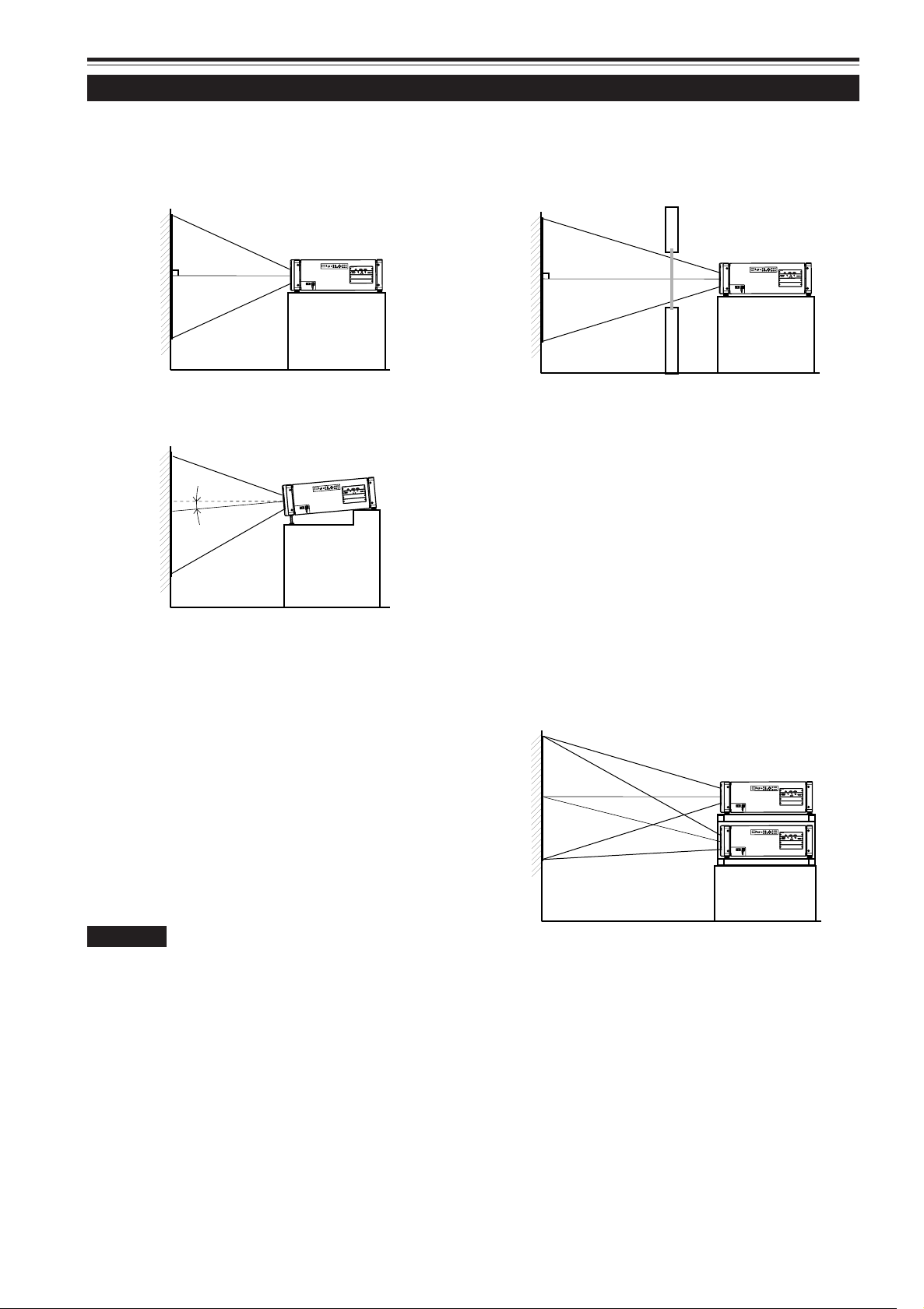
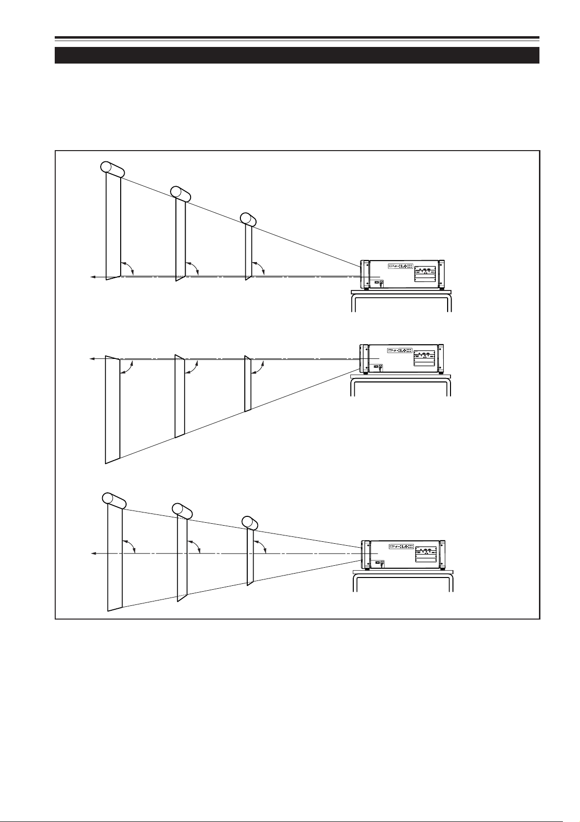
Installing the Projector against the Screen
The projector should be placed so that the center line of the lens is at a right angle to the screen as shown in the following
figures.
■ Normal projection
■ Inclined projection
■ Projection through the glass
• The brightness of the video image reduces when it is projected through the glass. It is not recommended that the
video image is projected through the plural glasses.
• Even if the projector is not installed at right angles to the
glass, you can enjoy the projection through the glass. In
this case, adjust the position of the projector and/or the
glass to avoid the diffused reflection.
■ Projection using stack configuration
Up to three projectors can be stacked and used together
(stack configuration).
Using two or more projectors together, high image brightness can be attained. This allows you to project sufficiently
bright image in a fairly large auditorium or relatively bright
place.
CAUTION
• To prevent damage to the projector during shipment, a shift center
lock pin was used to fix the lens mechanism when the projector was
shipped out the factory. If the lens does not either move up or down
by your lens shift adjustment using the buttons on the remote control
unit or the setting menu, the shift center lock pin might not have
been removed. In this case, consult your dealer or service center.
20
• When using the stack configuration, first install the frame
specially designed for the stack configuration. Decide the
installation place in the point of stability and efficiency for
ventilation.
• For the stack configuration, you need to use the lens with
the shift function.
Page 23
Installing the Projector (Cont.)
Projection Distance and Screen Size
The range of projection distances that can be focused depends on the lens unit (not supplied) to be used. When the aspect ratio
of the screen is 4:3, the range is as follows and you need to install the projector within this range.
Lens type Approximate projection distance
GL-MQ1010G 3.9 ft (1.2 m) to 25.9 ft (7.9 m)
GL-MQ1015SG 5.6 ft (1.7 m) to 40.3 ft (12.3 m)
GL-MQ1020ZG 26.2 ft (8.0 m) to 280.3 ft (85.5 m)
GL-MQ1023SZG 28.2 ft (8.6 m) to 276.1 ft (84.2 m)
The value for projection distance is a guide (reference). The projected image size may vary depending on the manufacturing tolerance of the projection lens.
Change of projection screen according to
aspect ratio
Screen with 4 : 3 aspect ratio
Screen with 16 : 9 aspect ratio
• For detailed relation between projection distances and projection screen sizes, refer to Appendix. The relation for both 4:3 and
16:9 are listed there.
• When adjusting the screen size, use a 4:3 aspect-ration picture. (A 16:9 aspect-ration picture is projected, based on the width
of a 4:3 aspect-ratio picture.)
• The diagonal length of a 16:9 aspect-ratio screen is about 91.8% that of a 4:3 aspect-ratio screen. This value is only a guide
(reference).
• If the keystone is adjusted, the projected screen becomes smaller.
■ Optional Lenses
This projector does not include a lens. You can select one of the optional lenses to adjust the projection distance. Please ask
your dealer to buy and install the lens.
Lens model Function
GL-MQ1010G Powered focus for rear projection, short focal length lens (subject ratio 1:1), 0% influence.
GL-MQ1015SG Powered focus, short focal length lens (subject ratio 1.5:1), manual vertical shift function pro-
vided, 0% to ±50% influence.
GL-MQ1020ZG Powered zoom/powered focus, long focal length lens (subject ratio 2.1:1 to 4.9:1), 0% influence.
GL-MQ1023SZG Powered zoom/powered focus, long focal length lens (subject ratio 3:1 to 7:1), manual vertical
shift function provided, 0% to ±50% influence.
ENGLISH
21
Page 24
Z
O
O
M
F
O
C
U
S
T
W
M
E
N
U
E
N
T
E
R
E
X
IT
V
IC
S
E
L
E
C
T
1
2
3
KE
Y
S
T
O
N
E
O
P
E
R
A
T
E
H
I
D
E
S
T
A
N
D
B
Y
R
E
M
O
T
E
CONTROL
R
S
-23
2
C
OU
T
R
S
-23
2
C
IN
Z
O
OM
F
O
CU
S
T
W
ME
N
U
E
N
TE
R
E
X
IT
V
I
C S
E
L
EC
T
1
2
3
KE
Y
S
TO
N
E
OP
E
R
A
T
E
H
I
DE
S
TA
N
D
B
Y
R
E
M
O
T
E
CONTROL
R
S
-
23
2
C
OU
T
R
S
-23
2
C
IN
R
G
B
Y
H/C
S
RGB Analog VIC
R
G
B
Y
H/C
S
RGB Analog VIC
90°
90°90°90°
90° 90°
Center line of the lens
Center line of the lens
For the lenses without the lens shift function
or when the lens shift is set to 0%
For the lenses with the lens shift function
When the lens shift is set to 50%
ZO
O
M
F
OC
U
S
T
W
M
E
N
U
E
N
T
E
R
E
X
IT
VIC
S
EL
E
C
T
1
2
3
KE
Y
ST
O
NE
O
P
ER
AT
E
H
ID
E
S
TA
ND
B
Y
R
E
M
O
T
E
C
ONTRO
L
R
S
-2
32
C
O
UT
R
S
-2
32
C
I
N
R
G
B
Y
H/C
S
RGB Analog VIC
90° 90° 90°
Center line of the lens
When the lens shift is set to –50%
Installing the Projector (Cont.)
Lens Shift Function
Some of the separately sold lenses have a lens shift function.
For the lens with the lens shift function: When the lens shift is set to 50%, install the projector so that the bottom edge of
the projection screen is at the same height as the center of the lens. When the lens shift is set to –50%, install the projector so
that the top edge of the projection screen is at the same height as the center of the lens .
For the lens without the lens shift function or when the lens shift is set to 0%: Install the projector so that the center of the
projection screen is at the same height as the center of the lens.
• When using the lens with the shift function, you can adjust the projected image vertically using the setting menu or the SHIFT
+/– buttons on the remote control unit.
• When using the projectors in stack configuration (stacked one over another), make adjustment so that the picture of each
projector overlaps exactly using the lens shift function. If the horizontal adjustment is needed, consult your dealer.
• For detailed adjustment procedures, refer to pages 38 and 46.
• For maximum amount of shift, refer to “Maximum amount of shift” on page 23. (When the lens needs to be adjusted in
horizontal angles, consult your dealer.)
22
Page 25
Installing the Projector (Cont.)
Lens Shift Function (Cont.)
Py(%)
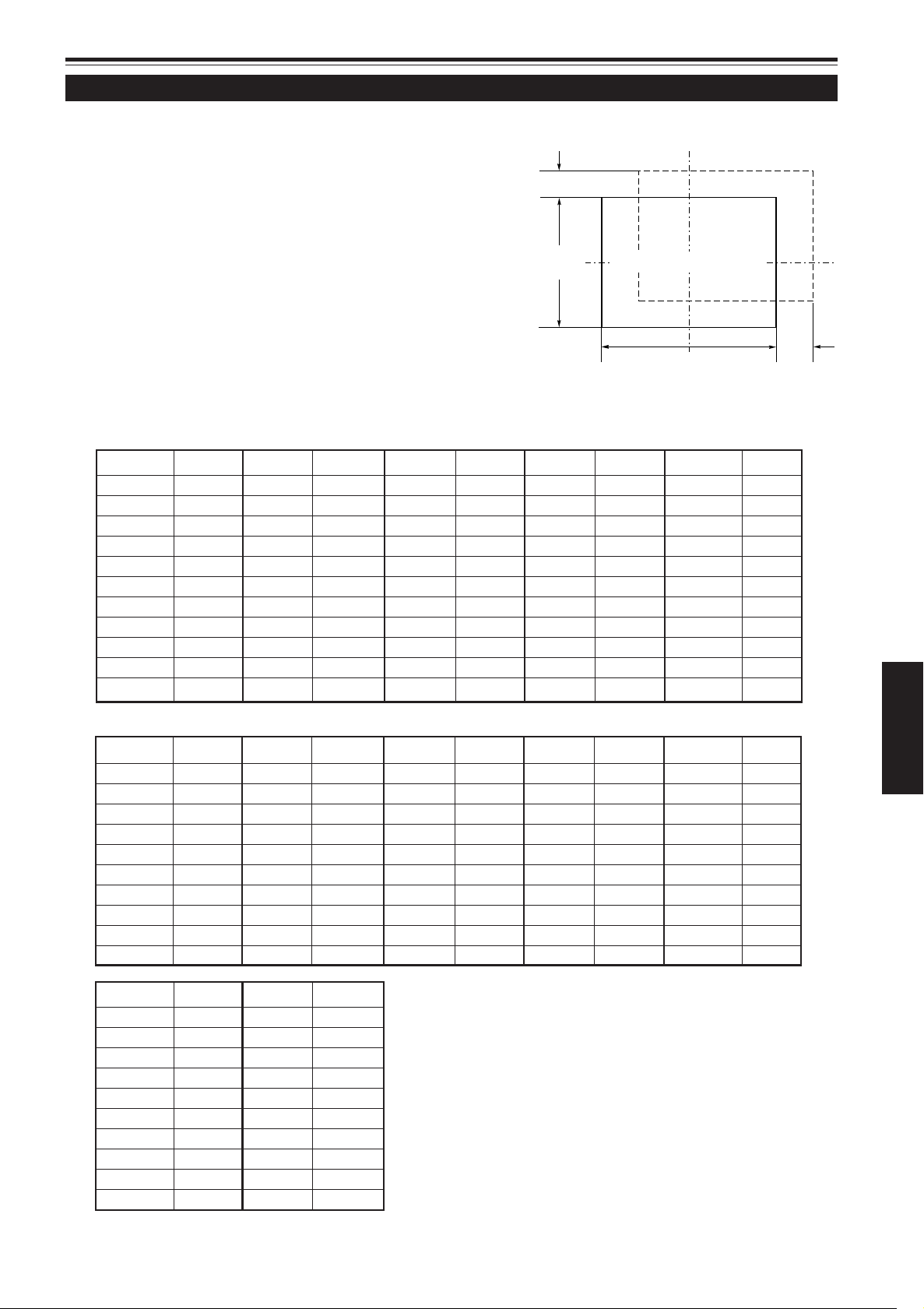
Maximum amount of shift
The maximum amount of vertical shift is restricted by the amount
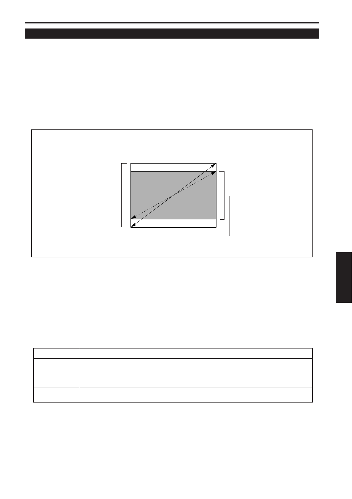
of horizontal shift made.
The amount of shift is defined as follows:
With the screen width taken as 1, horizontal shift is defined as a
ratio (%) of the screen width, while with the screen height taken
as 1, vertical shift is defined as a ratio (%) of the screen height.
Vertical screen size
(y): 100%
Relational table for maximum shift amounts (aspect ratio 4 : 3)
Py(%) Px(%) Py(%) Px(%) Py(%) Px(%) Py(%) Px(%) Py(%) Px(%)
0.0 32.0 10.0 28.1 20.0 23.3 30.0 17.3 40.0 9.7
1.0 31.6 11.0 27.7 21.0 22.7 31.0 16.6 41.0 8.9
2.0 31.3 12.0 27.2 22.0 22.2 32.0 15.9 42.0 8.0
3.0 30.9 13.0 26.8 23.0 21.6 33.0 15.2 43.0 7.1
4.0 30.5 14.0 26.3 24.0 21.0 34.0 14.5 44.0 6.2
5.0 30.1 15.0 25.8 25.0 20.4 35.0 13.7 45.0 5.2
6.0 29.8 16.0 25.3 26.0 19.8 36.0 13.0 46.0 4.2
7.0 29.4 17.0 24.8 27.0 19.2 37.0 12.2 47.0 3.2
8.0 28.9 18.0 24.3 28.0 18.6 38.0 11.4 48.0 2.2
9.0 28.5 19.0 23.8 29.0 17.9 39.0 10.6 49.0 1.2
Screen after shifted
Screen with zero (0) shift
Horizontal screen sized
(x): 100%
50.0 0.0
Px
(%)
Relational table for maximum shift amounts (aspect ratio 16 : 9)
Py(%) Px(%) Py(%) Px(%) Py(%) Px(%) Py(%) Px(%) Py(%) Px(%)
0.0 32.0 10.0 29.2 20.0 25.8 30.0 21.9 40.0 17.3
1.0 31.7 11.0 28.8 21.0 25.1 31.0 21.5 41.0 16.8
2.0 31.4 12.0 28.5 22.0 24.7 32.0 21.0 42.0 16.2
3.0 31.2 13.0 28.2 23.0 24.3 33.0 20.6 43.0 15.7
4.0 30.9 14.0 27.9 24.0 23.9 34.0 20.1 44.0 15.2
5.0 30.6 15.0 27.6 25.0 23.9 35.0 19.7 45.0 14.6
6.0 30.3 16.0 27.2 26.0 23.5 36.0 19.2 46.0 14.1
7.0 30.0 17.0 26.9 27.0 23.1 37.0 18.7 47.0 13.5
8.0 29.8 18.0 26.5 28.0 22.7 38.0 18.3 48.0 13.0
9.0 29.5 19.0 26.2 29.0 22.3 39.0 17.8 49.0 12.4
Py(%) Px(%) Py(%) Px(%)
50.0 11.8 60.0 5.2
51.0 11.2 61.0 4.5
52.0 10.6 62.0 3.7
53.0 10.0 63.0 3.0
54.0 9.3 64.0 2.2
55.0 8.7 65.0 1.4
56.0 8.0 66.7 0.0
57.0 7.3
58.0 6.6
59.0 5.9
ENGLISH
23
Page 26
Installing the Projector (Cont.)
ZOOM
KEYSTONE
SHUTTER
DIGITAL
ZOOM
SH
IFT FOC
US
OPERATE
EXIT
ME
NU
MODE
BACK
LIGHT
ENTER
VIC1
VIC2 VIC3
T
W
T
W
ON
OFF
LOCK
UNLOCK
RM-MQX1G REMOTE CONTROL UNIT
Z
O
O
M
F
O
C
U
S
T
W
M
E
N
U
E
N
T
E
R
E
X
I
T
V
I
C
S
E
L
E
C
T
1
2
3
K
E
Y
S
T
O
N
E
O
P
E
R
A
T
E
M
O
D
E
S
TA
N
D
B
Y
REMOTE
CONTROL
RS-232C OUT
RS-232C IN
A
15°
50°
B
Effective Range and Distance of the Remote Control Unit
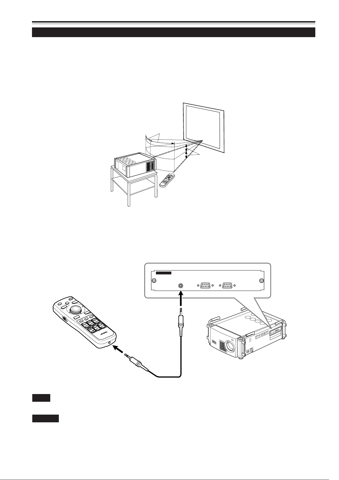
The remote control unit can be used as either a wireless remote control unit or a wired one.
■ Using as a wireless remote control unit
Aim the remote control unit as the remote sensor on the front or control panel of the projector.
The operable distance of the remote control unit is about 32.8 ft (10 m) for direct reception. The remote control unit can be used
by having its signal reflected on the screen. In this case, the total distance of “A + B” should be about 32.8 ft (10 m) or less. The
operable angles of the remote control unit are 50° horizontally, 15° vertically.
■ Using as a wired remote control unit
Connect the supplied remote control cable between the remote control unit and the REMOTE terminal on the connector panel
of the projector.
Using it as a wired remote control unit, you do not have to worry about the operable angle of the unit, though the operable
distance is limited by the length of the remote cable (approx. 49.2 ft (15 m)).
Note
• When the remote control unit is used as a wired unit, its signal transmitter and projector’s remote sensor do not work.
CAUTION
• Do not extend the remote cable. Doing so could cause a malfunction of the projector.
24
Page 27
Connecting to Various Devices
Signals that Can Be Input to the Projector
The following signals can be input to the projector through the corresponding VICs (Video Input Cards).
• Before connection, be sure to turn off the projector and devices.
• Read the manual which comes with each device thoroughly.
■ Analog RGB signals
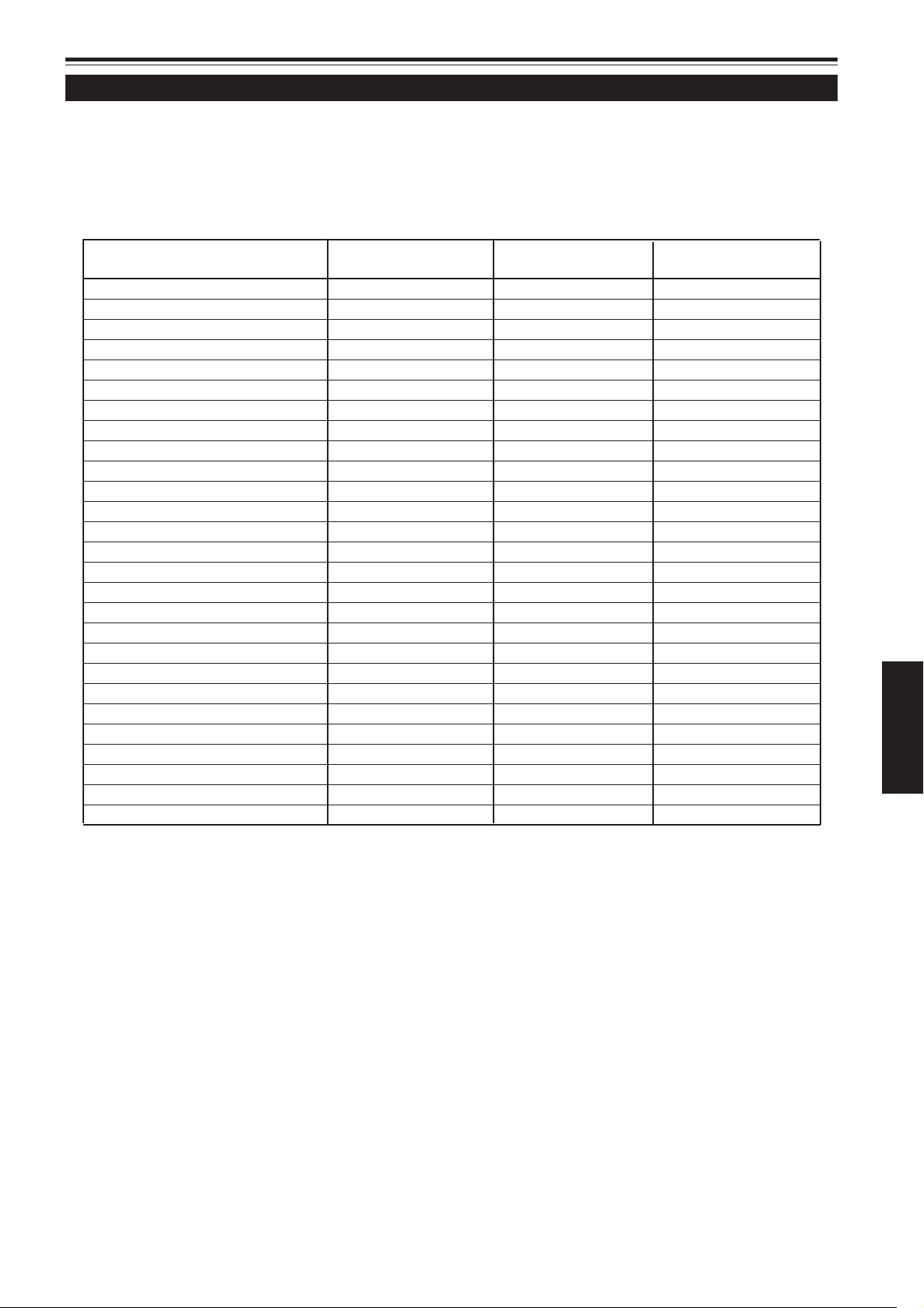
The signals with the following resolutions can be input to the input terminal of the RGB Analog VIC.
Screen resolution Horizontal Vertical Effective number of
(standard name) frequency frequency scanning line
DTV (480p 31.5kHz) 31.5Hz 59.9Hz 483
DTV (720p 60Hz) 45.0kHz 60.0Hz 720
DTV (1080p 60Hz) 67.5kHz 60.0Hz 1080
VGA (640 X 480 60Hz) 31.5kHz 59.9Hz 480
VGA (640 X 480 75Hz) 37.5kHz 75.0Hz 480
VGA (640 X 480 85Hz) 43.3kHz 85.0Hz 480
VGA (640 X 480 Macintosh 13") 35.0kHz 66.7Hz 480
SVGA (800 X 600 85Hz) 53.7kHz 85.0Hz 600
SVGA (832 X 624 Macintosh 16") 49.8kHz 74.6Hz 624
XGA (1024 X 768 60Hz) 48.4kHz 60.0Hz 768
XGA (1024 X 768 70Hz) 56.5kHz 70.1Hz 768
XGA (1024 X 768 75Hz) 60.0kHz 75.0Hz 768
XGA (1024 X 768 85Hz) 68.7kHz 85.0Hz 768
XGA (1024 X 768 Macintosh 19") 60.2kHz 74.9Hz 768
XGA (1024 X 768 Macintosh 21") 68.7kHz 75.1Hz 870
SXGA (1280 X 1024 60Hz) 63.9kHz 60.0Hz 1024
SXGA (1280 X 1024 67Hz) 70.8kHz 67.0Hz 1024
SXGA (1280 X 1024 75Hz) 79.9kHz 75.0Hz 1024
SXGA (1280 X 1024 76Hz) 81.2kHz 76.2Hz 1024
SXGA (1280 X 1024 85Hz) 91.1kHz 85.0Hz 1024
UXGA (1600 X 1200 60Hz) 75.0kHz 60.0Hz 1200
UXGA (1600 X 1200 65Hz) 81.2kHz 65.0Hz 1200
UXGA (1600 X 1200 70Hz) 87.5kHz 70.0Hz 1200
UXGA (1600 X 1200 75Hz) 93.8kHz 75.0Hz 1200
UXGA (1600 X 1200 85Hz) 106.3kHz 85.0Hz 1200
QXGA (2048 X 1536 60Hz) 95.3kHz 59.9Hz 1536
QXGA (2048 X 1536 60Hz) 95.7kHz 60.0Hz 1536
ENGLISH
• The RGB signals whose dot (pixel) clock is lower than 25 MHz or over 280 MHz are not available.
• The SVGA signals whose dot (pixel) clock is lower than 50 MHz are not available.
• When you want to input NTSC signal, make the signal twice as dense by a line doubler.
• The resolution and the scanning frequencies are within the range specified in the table on this page.
Be sure that the resolution and the scanning frequencies of the video signal are within the range. A video signal out of the
range cannot be used. (Even signals out of the range could be projected. However, it may not be sharp enough. On the
other hand, even some of the signals within the range may require adjustment depending on the video board used.)
When a signal other than listed in the table on this page is input, the image could be partially erased or an unneeded foldover image could appear.
Even signals within the frequency range may not be displayed normally depending on the type of the signal.
Composite sync (C
■ Analog HD signals
The HDTV interlaced signals can be input to the input terminal of the Analog HD VIC. NTSC is not available.
■ Digital HD signals
The digital HD signals can be input to the input terminal of the HD-SDI VIC as the SDI format (and can be output through).
S) and G on Sync signals cannot be handled depending on the devices connected.
25
Page 28
Connecting to Various Devices (Cont.)
ZOOM
FOCUS
T
W
MENU
ENTER
EXIT
VIC SELECT
1
23KEY STONE
OPERATE
HIDE
STAND BY
REMOTE
CONTROL
RS-232C OUT
RS-232C IN
B
G
R
V
H/C
S
RGB Analog VIC
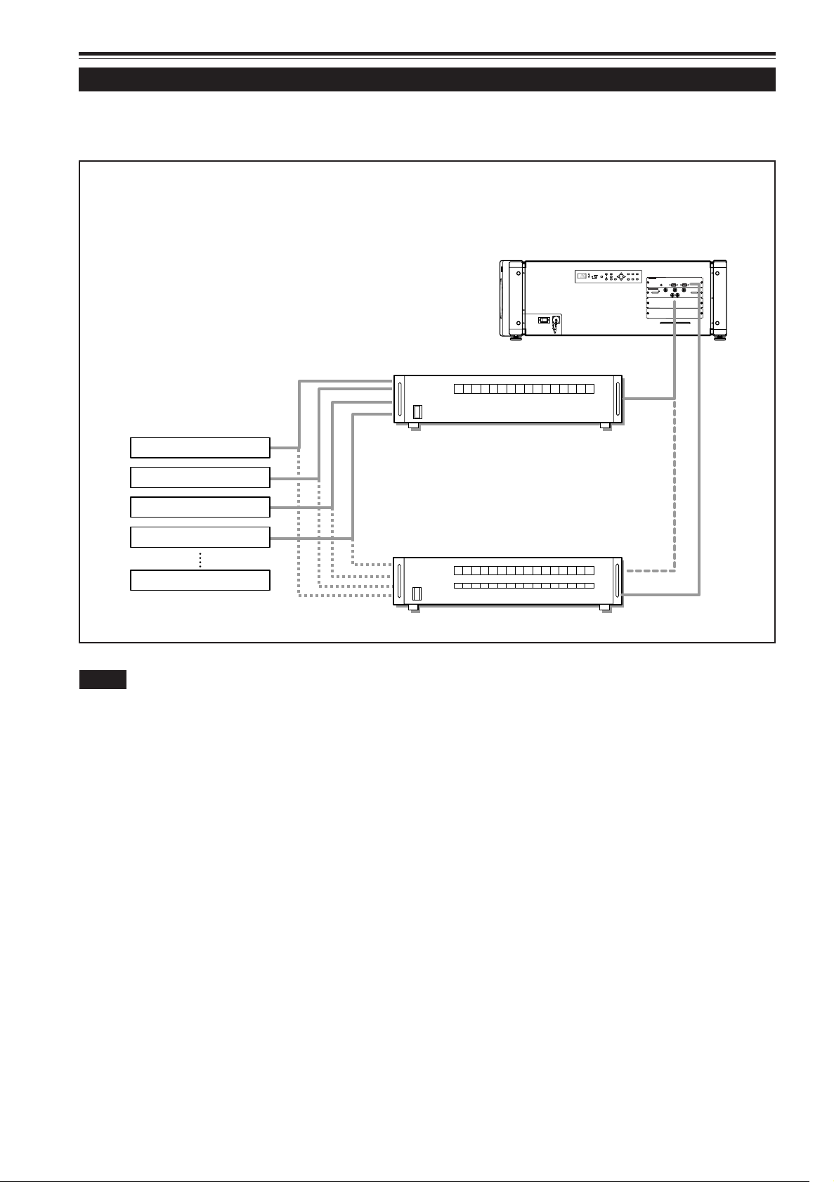
Examples of System Configuration
Before connection, be sure to turn off both the projector and the equipment.
• Also, read the manuals which came with the equipment.
Example of a basic system
• By connecting an RGB switcher, a variety of input sources can be input to the projector using RGB signals. Using the
remote control unit supplied, you can select the channel for an input source and project an image optimal to the source.
• By connecting the dedicated switcher, you can switch the channel of the projector automatically by selecting the channel on
the dedicated switcher.
RGB switcher (not supplied)
HDTV 1
Projector
HDTV 2
Computer 1
Dedicated switcher
Computer 2
(not supplied)
Notes
• Video image played back on devices, such as a VCR, whose image signal is unstable may be disturbed. (This may occur when the projector
is not yet adjusted at the time of installation, or when a new device is added.)
In such a case, consult your dealer to adjust the projector.
• For buying and installing the dedicated switcher, consult your dealer.
26
Page 29
Connecting to Various Devices (Cont.)
B
G
R
V
H/C
S
RGB Analog VIC
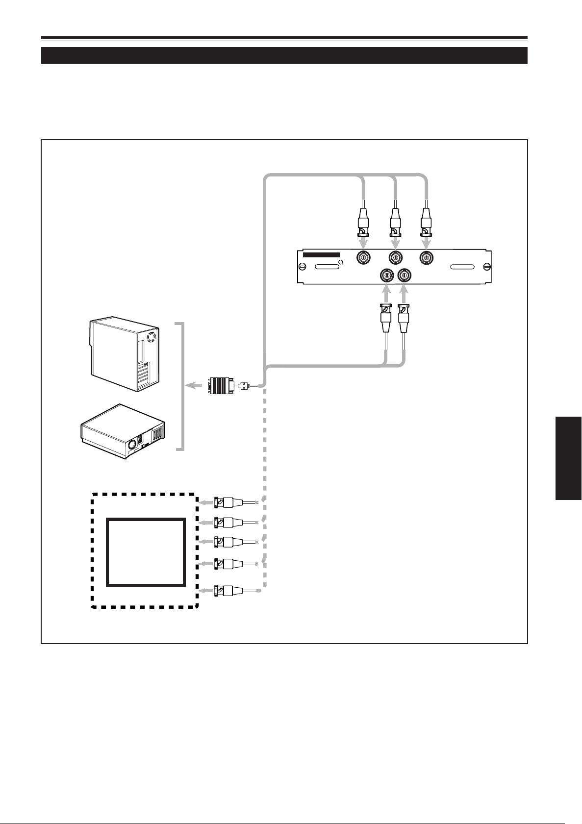
Connecting to RGB Devices
Before connection, be sure to turn off both the projector and RGB devices.
• Read the manuals which comes with each device thoroughly.
• Prepare and use separately available RGB connection cable.
• Detection of H/V signals or Cs signals causes automatic switch to external sync. The priority order is H/V > Cs.
• Desktop type
• RGB output devices
To monitor connector
RGB connection cable
(not supplied)
To V
To B
To G
To R
To H/Cs
ENGLISH
Laser video disc player, etc.
To R
To G
To B
To H/Cs
To V
27
Page 30
HDTV Analog VIC
Y
Pb
Pr
Connecting to Various Devices (Cont.)
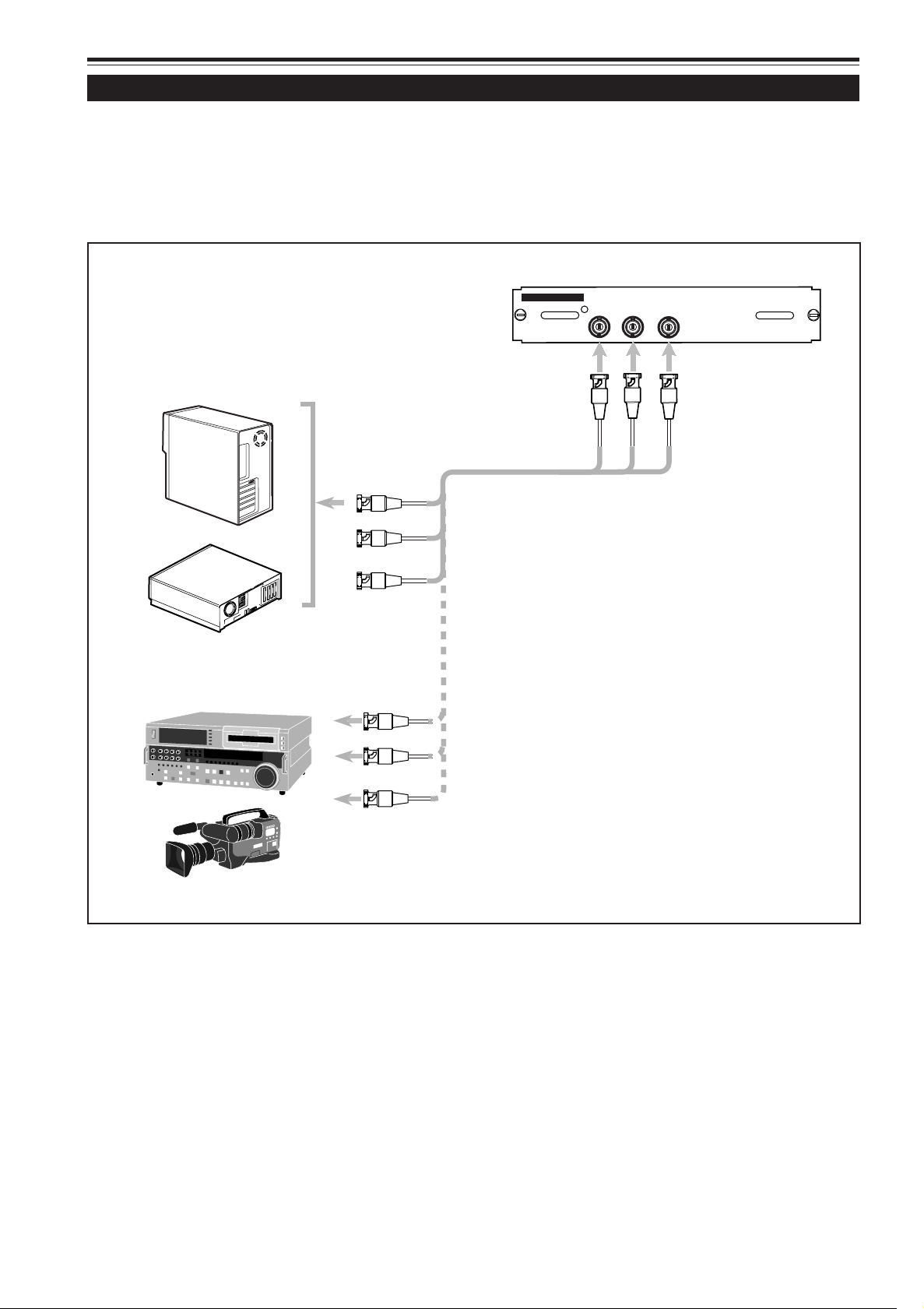
Connecting to Analog HD Devices
When you install an HDTV analog VIC (Video Input Card) to the projector, you can use analog HD devices equipped with the Y,
P
b, and Pr terminals.
Before connection, be sure to turn off both the projector and devices to be connected.
• Read the manual thoroughly which comes with each device to be connected.
• Prepare and use the separately available HD analog connection cable.
HDTV Analog VIC
• Desktop type
• Analog HD devices
To Y, P b, and Pr
To Y, P b, and Pr
To Y
To P b
HD Analog connection cable
(not supplied)
To P r
28
Page 31

HD-SDI VIC
IN
OUT
Connecting to Various Devices (Cont.)
Connecting to Digital HD Devices
When you install an HD-SDI VIC (Video Input Card) to the projector, you can use digital HD devices equipped with the SDI
interface.
Before connection, be sure to turn off both the projector and devices.
• Read the manual thoroughly which comes with each device to be connected.
• Prepare and use the separately available SDI coaxial connection cable.
HD-SDI VIC
• Digital HD devices
To OUT
To I N
To I N
To OUT
To I N
To OUT
SDI coaxial cable
(not supplied)
• Digital HD monitor
To I N
• The HD-SDI VIC has the OUT terminal, so you can also
connect the digital HD monitor or another device.
ENGLISH
29
Page 32

Connecting to Various Devices (Cont.)
REMOTE
CONTROL
RS-232C OUT
RS-232C IN
Connecting to Devices which Control the Projector
When you install a computer to the projector, you can operate the projector using the computer.
Before connection, be sure to turn off both the projector and computer.
• Read the manual thoroughly which comes with each device to be connected.
• Prepare and use the separately available RS-232C connection cable.
RS-232C connection cable
(not supplied)
• When another DLA-QX1G is connected to this projector using RS-232C OUT terminal, you can enable a computer to control
plural DLA-QX1Gs at the same time.
For details, consult your dealer.
30
Page 33

Connecting to Various Devices (Cont.)
Z
O
O
M
F
O
C
US
T
W
M
E
N
U
E
N
TE
R
E
X
IT
VI
C
S
E
LE
CT
1
2
3
K
E
Y
S
TO
N
E
O
PE
R
A
TE
M
O
DE
S
TA
N
D
BY
R
E
M
OT
E
C
O
N
T
R
O
L
RS
-
232
C
O
U
T
R
S
-23
2C IN
R
G
B
V
H
/C
S
RG
B
A
n
a
l
og
V
IC
To wall AC outlet
Connecting the Power Cord (Supplied)
After all devices have finished being connected, connect the projector’s power cord. At this time, do not turn on the MAIN
POWER switch yet.
• Do not turn on the projector without installing the lens unit (not supplied). Doing so will cause the lens-hole blind cover (black
one) initially installed to be deformed by heat from the light-source lamp.
■ Preparation for United Kingdom only
Attach a plug which matches your wall outlet to the power
code. For details, consult your dealer.
1
Power cord (supplied)
200 V to 240 V, single
2
phase
CAUTIONS
To prevent fire and electric shock, observe the following:
• When you do not use the devices, pull out their power cords from
wall outlets.
• Do not connect the devices with power cords other than supplied.
• Do not use voltage other than the power voltage indicated.
• Do not scar, damage, or work on the power cords. Also, do not put a
heavy object on, heat or pull the power cords, otherwise they may
be damaged.
• Do not insert or pull out the plugs with a wet hand.
1 Insert the supplied power cord
into the power input terminal (AC
IN
1. Remove the power input terminal cover.
2. Insert the plug of the supplied power cord into
) of the projector.
The cover is a screwed type. Turn the cover in the
direction of the arrow to remove.
the power input terminal of the projector.
Align the groove on the projector plug of the power
cord with the claw on the power input terminal of the
projector, and push the plug in firmly.
After that, turn the ring on the plug in the direction of
the arrow to fix.
2 Insert the plug of the supplied
power cord into a wall outlet.
ENGLISH
■ To use the projector
• Remove the lens cap before using the projector.
CAUTIONS
• Be sure to remove the cap; otherwise, it may be deformed (or
degraded in quality) or melted, possibly causing a fire or
malfunction.
• Do not operate the projector with the lens cap attached. Doing
so can deform the lens cap because of the heat. A metallic
lens cap can get hot and cause injury.
Lens cap
3 (For U.S.A. only)
Turn the plug to the right to fix.
CAUTIONS
• Since the power requirement of the projector is high, be sure to
insert the power plug directly into a wall outlet.
• This projector requires a single phase, 3-wire, 200V to 240V wall
outlet.
31
Page 34

Z
O
OM
FO
CUS
T
W
M
E
NU
EN
TE
R
E
X
IT
VIC
SE
LE
C
T
1
2
3
K
EY
S
T
ONE
OP
E
RA
T
E
M
ODE
ST
A
ND
B
Y
OPERATE
STAND BY
R
E
M
O
T
E
CONTROL
R
S
-
2
3
2
C
O
U
T
R
S
-
2
3
2
C
I
N
R
G
B
V
H
/
C
S
R
G
B A
n
alo
g
VI
C
Basic Operations
LOCK UNLOCK
HIDE
EXIT MENU
ENTER
OPERATE
BACK
LIGHT
OPERATE
STAND BY
OPERATE
STAND BY
OPERATE
OPERATE
■ Projector’s buttons
STAND BY indicator
Status code display
OPERATE indicator
OPERATE button
2
The following describes the basic procedure for common use
of the projector.
1. Turning On the Power
1 Turn on the MAIN POWER switch
of the projector.
ON [ ❙ ]:The main power turns on and the STAND BY
indicator comes on. “00” appears on the status
code display.
Projector’s indicator
2 Press the OPERATE button for one
second or more (either on the
control panel or on the remote
control unit).
• The OPERATE indicator comes on and “01” appears
on the status code display.
■ Remote control unit
MAIN POWER switch
OPERATE button
1
2
Remote control unit
Projector
Projector’s indicator
Notes
• After the power is turned on, the screen may appear jumbled for a
few seconds, but this is not a malfunction.
• After the OPERATE indicator comes on, it can take a minute or so
for the lamp to warm up and operate consistently.
32
Page 35

Basic Operations (Cont.)
OPERATE
OPERATE
OPERATE
STAND BY
Z
O
O
M
F
O
C
US
T
W
ME
N
U
EN
TE
R
E
XI
T
V
IC
SE
L
E
CT
1
2
3
K
E
Y
S
T
O
N
E
O
PE
R
A
T
E
M
O
D
E
ST
A
N
D
B
Y
OPERATE
STAND BY
REMOTE
CO
NTR
OL
R
S
-
2
3
2
C
O
U
T
R
S
-
2
3
2
C
IN
R
G
B
V
H/C
S
RGB A
nalog
VIC
LOCK UNLOCK
HIDE
EXIT MENU
ENTER
OPERATE
BACK
LIGHT
OPERATE
STAND BY
■ Projector’s buttons
STAND BY indicator
Status code display
OPERATE indicator
OPERATE button
1
■ Turning Off the Power
1 Press the OPERATE button for one
second or more (either on the
control panel or on the remote
control unit).
• The OPERATE indicator goes off and the STAND BY
indicator changes to blinking.
•“07” appears on the status code display.
Remote control unit
Projector
Projector’s indicator
■ Remote control unit
MAIN POWER switch
OPERATE button
2
1
Note
• You cannot cancel the turning-off process until “07” changes to “06”
or “00” on the status code display.
2 Turn off the MAIN POWER switch
when “00” appears on the status
code display.
‡‡
OFF [
‡]: The MAIN POWER switch turns off and the
‡‡
STAND BY indicator goes off.
Projector’s indicator
* Do not turn off the MAIN POWER switch until “00”
appears on the status code display (or while the STAND
BY indicator is blinking). The cooling fans continue
running about 10 minutes.
ENGLISH
Note
• To change the menu language displayed
English is selected when the projector is shipped from the factory.
The language displayed can be selected from the following six
languages: (Japanese), ENGLISH, DEUTSCH (German),
ESPAÑOL (Spanish), ITALIANO (Italian), and FRANÇAIS (French).
(To be continued on the next page)
33
Page 36

Basic Operations (Cont.)
VIC SELECT
1
2
3
VIC1 VIC 2 VIC 3
Z
O
O
M
F
O
C
US
T
W
M
EN
U
EN
T
E
R
EXI
T
V
IC
S
E
L
E
CT
1
2
3
K
E
Y
S
T
O
NE
O
P
E
R
AT
E
M
O
D
E
S
T
AN
D
B
Y
EXIT
VIC SELECT
1
2
3
KEY STONE
HIDE
REM
O
TE
CO
NTR
O
L
R
S
-2
3
2
C
O
U
T
R
S
-
2
3
2
C
IN
R
G
B
V
H/C
S
RGB
A
na
log VI
C
UNLOCK
EXIT
ZOOM
KEYSTONE
SHUTTER
DIGITAL
ZOOM
SHIFT FOCUS
VIC1 VIC2 VIC 3
MENU
ENTER
T
W
T
W
ON
OFF
VIC 1
■ Projector’s buttons
VIC SELECT 1, 2, 3 buttons
2.
Selecting the VIC to be projected
Press the VIC SELECT 1, 2, or 3 button to
select the desired VIC.
(Or press the remote control’s VIC 1, 2, or
3 button to select the desired VIC.)
Remote control unit
Screen display
Projector
Line display
■ Remote control unit
* When “5sec” is selected as the line display setting in
the menu, the line display is shown on the upper part of
the screen for about five seconds. However, it will not
be shown if the line display setting is set to “OFF.”
For details, refer to page 46.
Note
• When no signal comes into the projector through the selected VIC,
No signal menu appears on the screen. Refer to page 39.
VIC 1, 2, 3 buttons
34
Page 37

ZOOM
T
W
FOCUS
LOCK UNLOCK
HIDE
EXIT
ZOOM
KEYSTONE
SHUTTER
DIGITAL
ZOOM
SHIFT FOCUS
VIC1 VIC2 VIC 3
MENU
ENTER
OPERATE
BACK
LIGHT
T
W
T
W
ON
OFF
RM-MQX1G REMOTE CONTROL UNIT
Z
O
OM
F
O
C
US
T
W
M
E
N
U
E
N
T
ER
E
X
IT
V
I
C
S
E
LE
C
T
1
2
3
K
E
Y
S
T
O
NE
OP
ER
AT
E
M
O
DE
S
T
AN
D
B
Y
ZOOM
FOCUS
T
W+–
MENU
ENTER
R
E
MOT
E
C
ONT
ROL
R
S
-
2
3
2
C
O
U
T
R
S
-
2
3
2
C
I
N
R
G
B
V
H
/C
S
R
G
B A
nalo
g V
IC
ZOOM
T
W
FOCUS
–
+
Basic Operations (Cont.)
■ Projector’s buttons
ZOOM T/W buttons FOCUS +/– buttons
3. Adjusting the Screen Size
Adjust the screen size with the ZOOM T/W
buttons (either on the control panel or on
the remote control unit).
You can adjust the screen size using the ZOOM T/W buttons
only when you use the lens with the zoom function.
When adjusting the screen size with the ZOOM T/W buttons
on the remote control unit, set the LOCKÔUNLOCK switch
to the UNLOCK position.
■ To reduce the screen size:
Press the ZOOM T (Tele) button.
■ To enlarge the screen size:
Press the ZOOM W (Wide) button.
Remote control unit
Projector
■ Remote control unit
LOCK
UNLOCK
switch
ZOOM T/W
buttons
FOCUS +/–
buttons
4. Adjusting Focus
Adjust focus with the FOCUS +/– buttons
(either on the control panel or on the remote
control unit).
When adjusting the focus with the FOCUS +/– buttons on the
remote control unit, set the LOCKÔUNLOCK switch to the
UNLOCK position.
■ To focus on farther points:
Press the FOCUS + button.
■ To focus on nearer points:
Press the FOCUS – button.
Remote control unit
Projector
ENGLISH
(To be continued on the next page)
35
Page 38

Basic Operations (Cont.)
HIDE
HIDE
Z
O
O
M
F
O
C
US
T
W
M
E
NU
EN
T
E
R
E
X
IT
V
IC
SE
L
E
CT
1
2
3
KE
Y
S
T
O
N
E
O
PE
RA
T
E
M
OD
E
S
T
AN
D B
Y
EXIT
VIC SELECT
1
2
3
KEY STONE
HIDE
R
E
M
O
T
E
CONTROL
R
S
-2
3
2
C
O
U
T
R
S
-
2
3
2
C
I
N
R
G
B
V
H
/C
S
R
GB
Analog VIC
LOCK UNLOCK
HIDE
EXIT
ZOOM
KEYSTONE
SHUTTER
DIGITAL
ZOOM
SHIFT FOCUS
VIC1 VIC2 VIC 3
MENU
ENTER
OPERATE
BACK
LIGHT
T
W
T
W
ON
OFF
RM-MQX1G REMOTE CONTROL UNIT
SHUTTER
ON
OFF
■ Projector’s buttons
■ Remote control unit
HIDE button
HIDE button
For Operating Other Functions
■ Turning off video image (HIDE)
Video image can be turned off temporarily.
Press the HIDE button once:
Video image turns off temporarily.
Press the HIDE button again:
Video image comes on again.
Remote control unit
Note
• When the video image input is changed, the HIDE function is
canceled and new image will appear.
■ Interrupting the projection light while
video image stops (SHUTTER)
When video image stops, you can interrupt the projection
completely using the shutter function.
Press the SHUTTER ON button on the remote control
unit:
The projection is interrupted temporarily.
Press the SHUTTER OFF button on the remote control
unit:
The projection is displayed again.
Projector
36
SHUTTER
ON/OFF
buttons
Remote control unit
Note
• When the shutter function is activated, “03” appears in the status
code display.
CAUTION
• When the shutter function is activated, the temperature inside the
projector rises up faster than usual.
Page 39

Z
OOM
F
OC
US
T
W
M
E
NU
E
NT
E
R
E
X
IT
V
IC
S
E
L
E
CT
1
2
3
KE
Y
STO
N
E
OP
E
RAT
E
MO
DE
ST
A
ND B
Y
EXIT
VIC SELECT
1
2
3
KEY STONE
HIDE
REMO
TE
CONTROL
R
S
-
2
3
2
C
O
U
T
R
S
-
2
3
2
C
I
N
R
G
B
V
H
/C
S
R
GB
Ana
log
V
I
C
LOCK UNLOCK
HIDE
EXIT
ZOOM
KEYSTONE
SHUTTER
DIGITAL
ZOOM
SHIFT FOCUS
VIC1 VIC2 VIC 3
MENU
ENTER
OPERATE
BACK
LIGHT
T
W
T
W
ON
OFF
RM-MQX1G REMOTE CONTROL UNIT
Basic Operations (Cont.)
KEYSTONE
KEY STONE
Keystone 115
■ Projector’s buttons
KEYSTONE buttons
EXIT button
■ Removing the trapezoidal distortion of the
image (KEYSTONE)
If the image projected on the screen is distorted in trapezoid
form, correct it with the KEYSTONE buttons. When the
KEYSTONE button is pressed, the keystone indication
appears on the screen.
Keystone indication
Press the KEYSTONE
The trapezoid form is corrected as shown in the figure.
Remote control unit Projector
/ buttons:
■ Remote control unit
EXIT button
KEYSTONE
buttons
Notes
• Before adjusting the trapezoidal distortion, adjust the shift setting.
For details, refer to page 38.
• The trapezoidal distortion (keystone) can be adjusted within the range
of 0 to 127.
• Adjustable range for correcting trapezoidal distortion (keystone) is
0˚ to +15˚.
When “Aspect” or “Panel” is selected as the Resize setting (see
page 44), the adjustable range is limited as follows:
– While UXGA or SXGA signals are inputted, the range is 0˚ to +10˚.
– While analog HD signals are inputted, you cannot make any
adjustment.
• The trapezoidal distortion (keystone) can be adjusted from the menu.
For details, refer to page 46.
• Interference patterns may appear on the screen when adjusting the
keystone. This is not a malfunction.
• Depending on the type of signal, some noise may appear in the
picture when the keystone is adjusted. In this case, consult your
dealer.
ENGLISH
(To be continued on the next page)
37
Page 40

Basic Operations (Cont.)
SHIFT
LOCK UNLOCK
HIDE
EXIT
ZOOM
KEYSTONE
SHUTTER
DIGITAL
ZOOM
SHIFT FOCUS
VIC1 VIC2 VIC 3
MENU
ENTER
OPERATE
BACK
LIGHT
T
W
T
W
ON
OFF
RM-MQX1G REMOTE CONTROL UNIT
ZOO
M
FO
CU
S
T
W
MENU
ENT
ER
EX
I
T
VIC SELE
CT
1
2
3
KEY S
T
O
NE
O
PER
A
T
E
H
I
D
E
ST
AND B
Y
R
E
M
O
T
E
C
O
N
T
R
O
L
R
S
-
2
3
2
C
O
U
T
R
S
-
2
3
2
C
I
N
R
E
M
O
T
E
C
O
N
T
R
O
L
R
S
-
2
3
2
C
O
U
T
R
S
-
2
3
2
C
I
N
R
G
B
Y
H/C
S
RGB Analog VIC
■ Remote control unit
SHIFT +/–
buttons
■ Setting the amount of lens shifting
(SHIFT)
When the lens unit (not supplied) has the lens shifting function,
the projected screen can be moved vertically in position.
• When using the projectors in stack configuration (stacked
one over another), make adjustment so that the picture of
each projector overlays exactly using the lens shift function.
Press the SHIFT + button:
The lens shifts upward.
Press the SHIFT – button:
The lens shifts downward.
Remote control unit
38
Notes
• The amount of shifting is within the range of approx. –50% to 50%.
• When the lens shift is set to 0%, the center of the projection screen
is the same height as the center of the lens.
When the lens shift is set to 50%, the bottom edge of the projection
screen is at the same height as the center of the lens. When the
lens shift is set to –50%, the upper edge of the projection screen is
at the same height as the center of the lens.
Page 41

Language
English
Deutsch
Español
Italiano
Français
Main : Options
Language menu
Back to “Main : Options”
Right Left rev.
RS-232C [bps]
Sleep time [min]
15 30 60 OFF
9600 19200
OFF ON
Options
Options menu
Main : Information
VIC Slot 1
Switcher
Resolution
Frequency H
Frequency V
Lamp time
RGB
CH.0
1024 x 768
48.5kHz
80 Hz
123 h
Menu
Image adj.
Setting
VIC menu
Options
Language
Information
Right Left rev.
RS-232C[bps]
Sleep time [min]
Menu
Image adj.
Setting
VIC menu
Options
Language
Information
Main menu Sub menu 1
Main : Language
Image adj.
Setting
VIC menu
Options
Language
Information
Menu
English
Deutsch
Español
Italiano
Français
Menu Operations
You can adjust picture quality, set functions, get information on the input video signal, etc. using the menus. From the following
diagrams, you can see the overall menus. Note that there are three menu modes: No signal menu mode, RGB VIC menu mode
and HDTV/HD-SDI VIC menu mode. When the MENU button is pressed, the projector enters one of these modes by judging
the input signal being received.
■ No signal menu mode
The following diagram shows the menu transition when there is no signal input through the selected VIC.
Note
• The display languages of the menus are set to “English” when
shipped from the factory. The display language can be selected from
the following 6 languages: “ (Japanese),” “English,” “Deutsch
(German),” “Español (Spanish),” “Italiano (Italian)” and “Français
(French).” The language settings in this section are explained using
English menus.
For details, refer to page 46.
(To be continued on the next page)
ENGLISH
39
Page 42

Back to “Main : Image adj.”
Keystone 0
Keystone menu
Main : Setting
Disp.Posi.
Resize
Image adj.
Setting
VIC menu
Options
Language
Information
Menu
Main : VIC menu
Tracking
Phase
AD sync adj.
Offset & Gain
Clamp
Image adj.
Setting
VIC menu
Options
Language
Information
Menu
Main : Options
Menu position
Menu display
Line display
Keystone
Right Left rev.
RS-232C [bps]
Sleep time [min]
Back color
Lens shift
Image adj.
Setting
VIC menu
Options
Language
Information
Menu
Main : Information
VIC Slot 1
Switcher
Resolution
Frequency H
Frequency V
Lamp time
RGB
CH.0
1024 x 768
48.5kHz
80 Hz
123 h
Menu
Image adj.
Setting
VIC menu
Options
Language
Information
Main : Image adj.
Contrast
Brightness
Color temp.
Gamma
Sub brightness
Menu
Image adj.
Setting
VIC menu
Options
Language
Information
Contrast
Brightness
Color temp.
Gamma
Sub brightness
Image adj.
ENTER
12 3
Image adj. menu
123
123
ENTER
Color temp.
ENTER
5500K
6500K
User 1
User 2
ENTER
Color temp. menu
R
G
B
Sub brightness
123
123
123
Sub brightness menu
Setting menu
Disp.Posi.
Resize
Setting
1:1 Panel Aspect
ENTER
3
VIC menu
Tracking
Phase
AD sync adj.
Offset & Gain
Clamp
1020
12
VIC menu
BP
ST
ENTER
123
Disp.Posi.
Scanning position
Disp.Posi. menu
Picture position
ENTER
Menu position
Menu display
Line display
Keystone
Options 2
ENTER
5sec OFF
15sec ON
Options 1
ENTER
Options 1 menu
ENTER
Offset R
Offset G
Offset B
Gain R
Gain G
Gain B
Offset & Gain
123
123
123
123
123
123
Offset & Gain menu
Menu position
Menu position menu
Right Left rev.
RS-232C [bps]
Sleep time [min]
Back color
Lens shift
Options 1
ENTER
15 30 60 OFF
9600 19200
OFF ON
Options 2
Options 2 menu
ENTER
BLUE BLACK
Lens shift
DOWN
UP
Lens shift menu
Main menu Sub menu 1 Sub menu 2 Sub menu 3
Main : Language
Image adj.
Setting
VIC menu
Options
Language
Information
Menu
English
Deutsch
Español
Italiano
Français
Language
English
Deutsch
Español
Italiano
Français
Language menu
R
G
B
User 1
User 1 menu
123
123
123
User 2
User 2 menu
R
G
B
123
123
123
Menu Operations (Cont.)
■ RGB VIC menu mode
The following diagram shows the menu transition when there is signal input through the RGB VIC.
40
Note
• The display languages of the menus are set to “English” when
shipped from the factory. The display language can be selected from
the following 6 languages: “ (Japanese),” “English,” “Deutsch
(German),” “Español (Spanish),” “Italiano (Italian)” and “Français
(French).” The language settings in this section are explained using
English menus.
For details, refer to page 46.
Page 43

Menu Operations (Cont.)
Back to “Main : Image adj.”
Keystone 0
Keystone menu
Main : Setting
Disp.Posi.
Resize
Image adj.
Setting
VIC menu
Options
Language
Information
Menu
Main : VIC menu
Tint
Color
Sharpness
Phase
HDTV
MAIP
2-2/2-3 Pulldown
Image adj.
Setting
VIC menu
Options
Language
Information
Menu
Main : Options
Menu position
Menu display
Line display
Keystone
Right Left rev.
RS-232C [bps]
Sleep time [min]
Back color
Lens shift
Image adj.
Setting
VIC menu
Options
Language
Information
Menu
Main : Information
VIC Slot 1
Switcher
Source
Lamp time
RGB
CH.0
1080/50i
123 h
Menu
Image adj.
Setting
VIC menu
Options
Language
Information
Main : Image adj.
Contrast
Brightness
Color temp.
Gamma
Sub brightness
Menu
Image adj.
Setting
VIC menu
Options
Language
Information
Contrast
Brightness
Color temp.
Gamma
Sub brightness
Image adj.
ENTER
12 3
Image adj. menu
123
123
ENTER
Color temp.
ENTER
5500K
6500K
User 1
User 2
ENTER
Color temp. menu
R
G
B
Sub brightness
123
123
123
Sub brightness menu
Setting menu
Disp.Posi.
Resize
Setting
1:1 Panel Aspect
ENTER
VIC menu 1
Disp.Posi.
Scanning position
Disp.Posi. menu
Picture position
ENTER
Menu position
Menu display
Line display
Keystone
Options 2
ENTER
5sec OFF
15sec ON
Options 1
ENTER
Options 1 menu
ENTER
Menu position
Menu position menu
Right Left rev.
RS-232C [bps]
Sleep time [min]
Back color
Lens shift
Options 1
ENTER
15 30 60 OFF
9600 19200
OFF ON
Options 2
Options 2 menu
ENTER
BLUE BLACK
Lens shift
DOWN
UP
Lens shift menu
Main menu Sub menu 1 Sub menu 2 Sub menu 3
Main : Language
Image adj.
Setting
VIC menu
Options
Language
Information
Menu
English
Deutsch
Español
Italiano
Français
Language
English
Deutsch
Español
Italiano
Français
Language menu
R
G
B
User 1
User 1 menu
123
123
123
User 2
User 2 menu
R
G
B
123
123
123
3
Tint
Color
Sharpness
Phase
VIC menu 2
VIC menu 1
ENTER
123
123
123
123
HDTV
MAIP
2-2/2-3 Pulldown
VIC menu 1
VIC menu 2
ENTER
Auto
OFF
ON
OFF
1035i1080i
VIC menu 2
■ HDTV VIC or HD-SDI VIC menu mode
The following diagram shows the menu transition when there is signal input through the HDTV VIC or the HD-SDI VIC.
ENGLISH
Note
• The display languages of the menus are set to “English” when
shipped from the factory. The display language can be selected from
the following 6 languages: “ (Japanese),” “English,” “Deutsch
(German),” “Español (Spanish),” “Italiano (Italian)” and “Français
(French).” The language settings in this section are explained using
English menus.
For details, refer to page 46.
41
Page 44
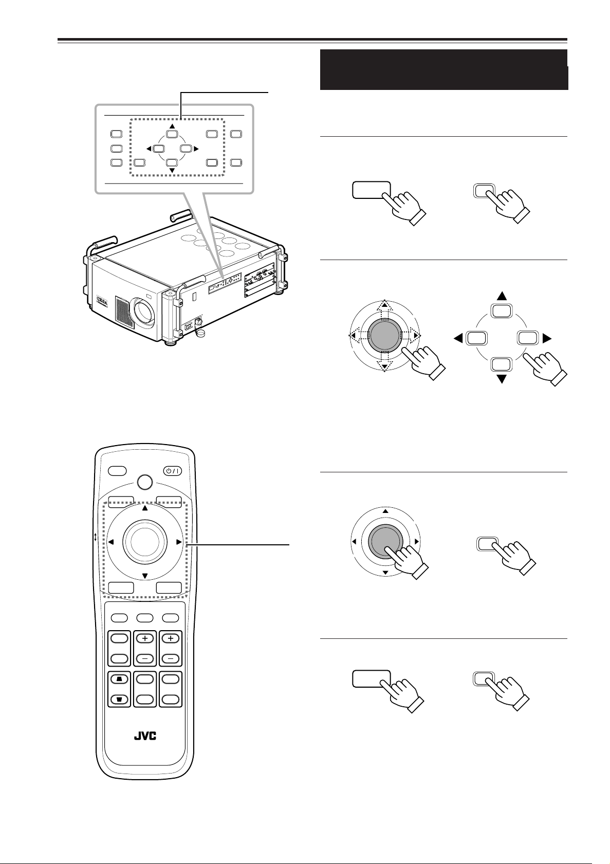
Z
O
O
M
F
O
C
U
S
T
W
M
E
N
U
EN
T
ER
E
X
IT
V
I
C
S
E
LE
C
T
1
2
3
K
E
Y S
T
ON
E
O
PE
RA
T
E
M
OD
E
ST
A
N
D
BY
ZOOM
T
W
MENU
ENTER
EXIT
VIC SELECT
1
2
3
R
E
MOT
E
C
ON
TR
O
L
R
S
-
2
3
2
C
O
U
T
R
S
-
2
3
2
C
I
N
R
G
B
V
H/C
S
RGB An
alog
VIC
LOCK UNLOCK
HIDE
EXIT
ZOOM
KEYSTONE
SHUTTER
DIGITAL
ZOOM
SHIFT FOCUS
VIC1 VIC2 VIC 3
MENU
ENTER
OPERATE
BACK
LIGHT
T
W
T
W
ON
OFF
RM-MQX1G REMOTE CONTROL UNIT
ENTER
EXIT
EXIT
ENTER
MENU
MENU
ENTER
Menu Operations (Cont.)
■ Projector’s buttons
Menu operating buttons
Buttons and Control for
the Menu Operations
The buttons and control listed below can be used for the menu
operation.
■ To display the main menu
Remote control unit Projector
• When the menu is displayed, you can clear the menu by pressing
the button.
■ To select or adjust the item
Remote control unit Projector
■ Remote control unit
• 5/∞ usually works for selecting the item. When “Color temp.
menu,” “Menu position menu” or “Lens shift menu” is displayed,
the buttons work for adjusting each item.
• 2/3 usually works for adjusting the item. When “Disp.Posi. menu”
is displayed, the buttons work for selecting the item. When
“Language menu” or “Lens shift menu” is displayed, the buttons
do not work.
■ To go to the sub menu
Remote control unit Projector
Menu operating
control and buttons
• The ENTER button usually works for going to the sub menu.
When “Disp.Posi. menu” is displayed, the button works for setting
the adjustment. When “Options 1” in “Options 2 menu” or “VIC
menu 1” in “VIC menu 2” is selected, you can go back to the
previous menu by pressing the button.
■ To go back to the previous screen
Remote control unit Projector
42
• When the main menu is displayed, you can clear the menu by
When using the remote
pressing the button.
control unit, refer to “Cursor
(5/∞/2/3) / ENTER
(Menu Operation) Button”
on page 16.
Page 45

Z
O
OM
F
O
CU
S
T
W
ME
N
U
EN
T
E
R
E
X
IT
VIC
SE
L
E
C
T
1
2
3
K
E
Y
S
T
O
N
E
O
P
E
R
A
TE
M
O
D
E
S
T
A
ND
B
Y
ZOOM
T
W
MENU
ENTER
EXIT
VIC SELECT
1
2
3
R
E
MOTE
CO
NTRO
L
R
S
-2
3
2
C
O
U
T
R
S
-
2
3
2
C
I
N
R
G
B
V
H/C
S
RGB An
alog
VIC
LOCK UNLOCK
HIDE
EXIT
ZOOM
KEYSTONE
SHUTTER
DIGITAL
ZOOM
SHIFT FOCUS
VIC1 VIC2 VIC 3
MENU
ENTER
OPERATE
BACK
LIGHT
T
W
T
W
ON
OFF
RM-MQX1G REMOTE CONTROL UNIT
Contrast
Brightness
Color temp.
Gamma
Sub brightness
Menu
Image adj.
Setting
VIC menu
Options
Language
Information
3
Tracking
Phase
AD sync adj.
Offset & Gain
Clamp
1020
12
VIC menu
BP
ST
ENTER
123
3
Tint
Color
Sharpness
Phase
VIC menu 2
VIC menu 1
ENTER
123
123
123
123
Menu Operations (Cont.)
■ Projector’s buttons
Menu operating buttons
Menu Operation Procedure
Press the MENU button.
1
The main menu appears.
• When the video image is projected on the screen, the
menu corresponding to the input signal is displayed.
When there is no signal, No signal menu is displayed.
is indicated on
the selected item.
The item list of the sub
menu appears.
Ex. “Main : Image adj.”
Press ∞/5 to select the item in
2
the main menu.
• When “Information” is selected, the information about
the input video image appears on the right side of the
menu.
Press the ENTER button or 3 to
3
go to the sub menu.
The sub menu appears.
■ Remote control unit
Menu operating
control and buttons
Ex. “VIC menu” in RGB VIC
menu
Press ∞/5 to select the item in
4
the sub menu.
• When “Language menu” is displayed, select the desired
language in this step. Then, go to step 6.
Press 3/2 to adjust the selected
5
item.
Ex. “VIC menu 1” in HD VIC
menu
ENGLISH
• When the item with indication is selected, you
can go to the next sub menu by pressing the ENTER
button. Then, adjust the item using 3/2.
Press EXIT to go back to the
6
previous screen.
• Each time you press the button, you can go back to the
previous screen.
Repeat steps 2 to 6 to adjust the
7
other items.
Press the MENU button to clear
8
When using the remote
the menu screen.
control unit, refer to “Cursor
(5/∞/2/3) / ENTER
(Menu Operation) Button”
on page 16.
43
Page 46

Contrast
Brightness
Color temp.
Gamma
Sub brightness
Menu
Image adj.
Setting
VIC menu
Options
Language
Information
VIC Slot 1
Switcher
Source
Lamp time
RGB
CH.0
1080/50i
123 h
Menu
Image adj.
Setting
VIC menu
Options
Language
Information
VIC Slot 1
Switcher
Resolution
Frequency H
Frequency V
Lamp time
RGB
CH.0
1024 x 768
48.5kHz
80 Hz
123 h
Menu
Image adj.
Setting
VIC menu
Options
Language
Information
Contrast
Brightness
Color temp.
Gamma
Sub brightness
Image adj.
ENTER
12 3
123
123
ENTER
Disp.Posi.
Resize
Setting
1:1 Panel Aspect
ENTER
Menu Operations (Cont.)
Contents of the Menu
The values in the [ ] are initial settings.
■ Information in Main menu
The following information about the input video image appears
on this screen.
Ex. “Main : Information” in
RGB VIC menu
VIC Slot : Shows the VIC name selected by the VIC 1,
2, or 3 button.
Switcher : Shows the selection number of the switcher
connected to the projector. “CH.0” means that
the switcher is not being used.
For details about the switcher, consult your
dealer.
● For RGB VIC
Resolution : Shows the resolution of the RGB signal
being received (Horizontal x Vertical).
It may not be displayed correctly for some
input signals.
Frequency H : Shows the horizontal frequency of the RGB
signal being received.
Frequency V : Shows the vertical frequency of the RGB
signal being received.
● For HD/HD-SDI VIC
Source : Shows one of the following formats
corresponding to the input HDTV/HD-SDI
signal.
[1035/60i, 1080/60i, 1080/50i, 1080/30p,
1080/25p, 1080/24p, 1080/25sF, 720/60p]
Lamp time : Shows the accumulated use hours of the light-
source lamp.
44
Ex. “Main : Information” in
HD VIC menu
■ Image adj. menu
In this menu, the following items can be adjusted.
Contrast : The contrast of the video image being projected
is adjusted within the range of 0 to 255.
The larger value, the higher contrast is. [255]
Brightness : The brightness of the video image being projected
is adjusted within the range of 0 to 255.
The larger value, the brighter the image is.
[128]
Color temp. : Adjusts the color temperature of the video
image being projected. Make adjustment when
the video image becomes reddish or bluish.
Press the ENTER button to go to the next sub
menu. See “Color temp. menu” on page 46.
Gamma : Adjusts gamma correction within the range of
1 to 3.
The larger value, the stronger the gamma
correction is. [2]
Sub brightness : Adjusts the brightness for each RGB.
Press the ENTER button to go to the next sub
menu. See “Sub brightness menu” on page
46.
■ Setting menu
In this menu, the following items can be adjusted.
Disp.Posi. : Adjusts the position and size of the video
image being projected.
Press the ENTER button to go to the next sub
menu. See “Disp.Posi. menu” on page 47.
Resize : When the number of pixels (resolution) sought
by the video image input is smaller than that
(resolution) of D-ILA device—2048 x 1536, the
video image is then enlarged to a virtually full
screen size of D-ILA device and projected.
[Aspect]
1:1 : Does not enlarge the video image
for projection.
Panel : The video image is enlarged to the
full screen size of D-ILA device for
projection (resizing display).
Aspect : The video image is enlarged to the
full screen size of D-ILA device for
projection without changing the
original aspect ratio (resizing
display).
Page 47

3
Tracking
Phase
AD sync adj.
Offset & Gain
Clamp
1020
12
VIC menu
BP
ST
ENTER
123
3
Tint
Color
Sharpness
Phase
VIC menu 2
VIC menu 1
ENTER
123
123
123
123
HDTV
MAIP
2-2/2-3 Pulldown
VIC menu 1
VIC menu 2
ENTER
Auto
OFF
ON
OFF
1035i1080i
Menu Operations (Cont.)
Contents of the Menu (Cont.)
The values in the [ ] are initial settings.
■ VIC menu (VIC menu 1/2)
In this menu, the setting of the installed VIC can be adjusted.
When RGB VIC is selected as the current input terminal, “VIC
menu” is available. When HDTV/HD-SDI VIC is selected as
the current input terminal, “VIC menu1” and “VIC menu 2” are
available.
For RGB VIC
Tracking : Adjusts the lateral size and display area of
video image within the range of 0 to 4095.
Phase : Adjusts flickering or dim video image within
the range of 0 to 15.
AD sync adj. : Adjusts the outline of the text on the screen or
reduces the noise. To get the best picture,
select a value from the range of 0 to 255. [0]
Offset & Gain : Adjusts the offset and gain of the input signal
for each RGB.
Press the ENTER button to go to the next sub
menu. See “Offset & Gain menu” on page 47.
Clamp : Sets the clamp pulse’s position at the back
porch (BP) or on the sync tip (ST). Normally,
the clamp pulse is used at ST. If, with some
PCs or workstations, the screen becomes
unstable such as being too dark or too bright,
try to switch to BP. [ST]
For HDTV/HD-SDI VIC
• To alternate between the VIC menu 1 and the VIC menu 2,
press the ENTER button while the other menu is selected.
Tint : Adjusts the tint of the video image being
projected within the range of –30 to 30.
Normally select 0. [0]
Color : Adjusts the color density of the video image
being projected within the range of –30 to 30.
Normally select 0. [0]
Sharpness : Adjusts the sharpness of the video image
being projected within the range of –15 to 15.
Normally select 0. [0]
Phase : Adjusts flickering or dim video image within
the range of 0 to 15.
HDTV : Selects proper format to project the video
image of the HD signal with accurate 16:9
aspect ratio. [1080i]
1080i : Normally select this.
1035i : Select this when the video image is
not stable.
MAIP : Detects the degree of moving in the video
image and gets the best performance to project
the moving pictures. [ON]
ON : For the video image with a lot of moving
pictures.
OFF : For the video image with a lot of still
pictures.
2-2/2-3 Pulldown : Automatically adjusts the video image from
the film with quick action to be projected
properly. [AUTO]
OFF : Not to use this function.
AUTO : Normally select this.
ENGLISH
(To be continued on the next page)
45
Page 48

Menu position
Menu display
Line display
Keystone
Options 2
ENTER
5sec OFF
15sec ON
Options 1
ENTER
ENTER
Right Left rev.
RS-232C [bps]
Sleep time [min]
Back color
Lens shift
Options 1
ENTER
15 30 60 OFF
9600 19200
OFF ON
Options 2
ENTER
BLUE BLACK
Language
English
Deutsch
Español
Italiano
Français
Color temp.
ENTER
5500K
6500K
User 1
User 2
ENTER
R
G
B
Sub brightness
123
123
123
Menu Operations (Cont.)
Contents of the Menu (Cont.)
The values in the [ ] are initial settings.
■ Options menu
• To alternate between the Options 1 menu and the Options 2
menu, press the ENTER button while the other menu is
selected.
Menu position : Adjusts the position of the displayed menu.
Press the ENTER button to go to the next sub
menu. See “Menu position menu” on page 47.
Menu display : 15sec : Turns off the menu automatically in
15 seconds after operating the menu.
ON : Not to turn off the menu
automatically. If you want to turn it off,
press the MENU button. [15sec]
Line display : 5sec : Indicates the line display when the
video input is switched. The line
display goes off automatically in 5
seconds after switching to video input.
OFF : Does not indicate the line display.
[5sec]
Keystone : Adjusts the trapezoidal distortion of the
projected image.
Press the ENTER button to go to the next sub
menu. See “Keystone menu” on page 47.
Right Left rev. : ON : Reverses the video Image right-to-left.
OFF: Not to use this function. [OFF]
RS-232C [bps] : Sets the baud rate (transmission speed).
[19200]
Sleep time [min]
Back color : Specifies the background color shown when
Lens shift : Adjusts the lens shift.
: Sets the length of sleep time. A set sleep time
after input signal is depleted, the projector goes
into stand-by mode. (If you select “OFF,” the
sleep time will be cleared.) [OFF]
there is no video signal. [BLUE]
This function takes effect only when the
installed lens has the lens shift function.
Press the ENTER button to go to the next sub
menu. See “Lens shift menu” on page 47.
■ Language menu
Language : Text on the screen can be changed to a
language other than English. Languages that
can be displayed are the following six :
(Japanese), English, Deutsch (German),
Español (Spanish), Italiano (Italian), and
Français (French). [English]
■ Color temp. menu
Color temp. : Adjusts the white color of the video image
when it becomes reddish or bluish.
The higher the color temperature, the bluer
the video image is. [6500K]
5500K : Select this when the video image is
bluish.
6500K : Select this when the video image is
reddish.
User 1 or 2 : Select this when you want to
adjust the setting in detail.
Press the ENTER button to go to the
next sub menu. See “User 1 or 2
menu” on page 47.
■ Sub brightness menu
Sub brightness : Adjusts the brightness for each R/G/B within
the range of –128 to 127.
When all R/G/B signals are adjusted equally,
you can adjust the brightness of the video
image without changing its color temperature.
[0]
46
Page 49

Disp.Posi.
Scanning position
Picture position
ENTER
Offset R
Offset G
Offset B
Gain R
Gain G
Gain B
Offset & Gain
123
123
123
123
123
123
Menu position
Keystone 0
R
G
B
User 1
123
123
123
User 2
R
G
B
123
123
123
Lens shift
DOWN
UP
Menu Operations (Cont.)
Contents of the Menu (Cont.)
The values in the [ ] are initial settings.
■ Disp. Posi. menu
Disp.Posi. : Adjust the position and size of the video image
being projected using 5/∞/3/2. First, select
the projected area from whole video signal in
“Scanning position,” then press ENTER to
adjust the position of the projected area on
the screen in “Picture position.”
■ Offset & Gain menu
On this screen, the offset and gain of the input anolog signal
can be adjusted for each R/G/B. When you want to change
the black or white level, adjust all R/G/B signals equally.
Offset R : Adjusts the red level for black within the range
of –10 to 10. [0]
Offset G : Adjusts the green level for black within the
range of –10 to 10. [0]
Offset B : Adjusts the blue level for black within the range
of –10 to 10. [0]
Gain R : Adjusts the red level for white within the range
of –30 to 30. [0]
Gain G : Adjusts the green level for white within the
range of –30 to 30. [0]
Gain B : Adjusts the blue level for white within the range
of –30 to 30. [0]
■ Keystone menu
Keystone : Adjusts the trapezoidal distortion of the
projected image within the range of 0 to 127
using 3/2. [0]
■ User 1 or 2 menu
On this screen, you can adjust the color of the video image for
each R/G/B signal based on the selected color temperature
setting (5500K or 6500K).
R : Adjusts the red level of the selected color
temperature within the range of 0 to 255.
[255]
G : Adjusts the green level of the selected color
temperature within the range of 0 to 255.
[255]
B : Adjusts the blue level of the selected color
temperature within the range of 0 to 255.
[255]
■ Lens shift menu
ENGLISH
Lens shift : Adjusts the lens shift using 5/∞ when the
installed lens has the lens shift function.
■ Menu position menu
Menu position : Selects the display position of the menu from
the nine positions on the screen using
5/∞/3/2.
47
Page 50

Cleaning and Replacing the Filters
D-ILA SUPER PROJECTER
D-ILA SUPER PROJECTER
D-ILA SU
PER PR
OJEC
TER
The filters should be cleaned periodically to avoid the decline in the cooling efficiency and malfunction.
If they are heavily stained, do not become clean even if cleaned, or are damaged, replace them with new filters; otherwise, dirt
and dust may penetrate inside, possibly causing an adverse effect on the screen and preventing you from enjoying clear
pictures.
For replacing the filters or removing the inside dust of the projector, consult your dealer.
Bring the projector into stand-by
1
mode, and turn off the MAIN POWER
switch.
Put the projector into stand-by mode, and make sure “00”
appears on the status code display, then turn off the MAIN
POWER switch. After that, disconnect the power cord from
the wall outlet and the projector.
For details, refer to “Turning Off the Power” on page 33.
Remove the filter cover.
2
Using a Phillips screwdriver, remove the screws fixing each
filter cover.
Two filters are used, one on the left side (six screws) and
the other on the front (four screws) of the projector.
Remove the filters.
3
Pinch the center portion of the filter with your fingers
and pull it toward you.
(The filter is held by four tabs.)
48
Page 51

Clean the filters.
4
Wash the filter in water with neutral detergent, and dry it in the shade.
Reinstall the filters.
5
Reverse the procedure for removing. Finally, be sure to
reinstall the filter covers.
Notes
• Install the filters correctly; otherwise the projector will not operate
normally.
• If the filters and/or filter covers are damaged, the projector may fail
to operate. Then, replace with new parts.
CAUTIONS
• Put on rubber gloves when using neutral detergent.
• After you have washed the filters in water, make sure the
filters are completely dry before reinstalling them.
Otherwise, electric shock or malfunction could occur.
• Do not clean the filters using a vacuum cleaner. Since the
filters are soft, it may be sucked into the vacuum cleaner or
damaged.
ENGLISH
49
Page 52

Replacing the Light-Source Lamp
Lamp replacement
EXIT
Lamp replacement
Warning
EXIT
The light-source lamp has its service life. It is approximately 1000 hours.
When the light-source lamp approaches the end of its service life, degradation progresses rapidly.
The number display on the projector and the message on the screen warn you that replacement of the lamp is required.
■ When the lamp’s use hours exceed 900 hours
“80” appears on the status code display of
the projector.
At the start of projection (lamp energized),
the message “Lamp replacement” appears on
the projection screen for about two minutes.
In this case, the light-source lamp needs to be replaced.
• To cancel the message “Lamp replacement,” press the EXIT button.
• Each time the projector is turned on, the message appears.
■ When lamp’s use hours has reached 1000 hours
“81” appears on the status code display of
the projector.
• To cancel the message “ Warning Lamp replacement,” press the EXIT button. However, the same massage will appear
every one hour.
• Once the projector is turned off, it does not turn on until the light-source lamp is replaced with a new one.
The specified lamp replacement period is 1000 hours, but depending on use conditions, the replacement period may vary. If
video image is dark and its color tint is abnormal even after you have adjusted color tint and brightness, replace the light-source
lamp earlier.
For replacing the light-source lamp, consult your dealer.
“Warning Lamp replacement” appears on the
projection screen and the word “Warning”
blinks.
CAUTIONS
• If the projector is set up in a limited place which is unsuitable for work, and if you perform replacement work there, this could cause injury.
Move the projector to a place large enough for work, and then replace the light-source lamp.
• Use a genuine product for the light-source lamp. If you use other than a genuine product, this could cause a malfunction. Also, never use an
old light-source lamp. This could cause marked degradation in performance or the lamp could even explode, possibly damaging the projector
and/or injurying the operator.
• Do not replace the light-source lamp immediately after the projector has been used. The temperature of the light-source lamp is still high and
could cause a burn. Allow a cooling period of one hour or more before performing replacement.
• Before starting light-source lamp replacement work, turn off the MAIN POWER switch, and disconnect the power cord from the wall outlet. If
you perform the replacement work with the power cord connected, this could cause injury or electric shock.
• The light-source lamp used in this projector is a high pressure xenon lamp. Be careful when disposing of the light-source lamp. If anything is
unclear, please consult your dealer.
50
Page 53

Troubleshooting
Solutions to common problems related to your projector are described here. If none of the solutions presented here solves the
problem, unplug the projector and consult your dealer.
Symptom
Power is not
supplied.
Light is not
emitted, or light
level is low.
With power on,
operation starts
but stops in a few
minutes.
Video image does
not appear.
Video image dims.
Video image is
unstable.
Video image is
abnormally dark
or bright.
Image color is
poor or image is
disturbed.
Probable cause
• Is the power cord disconnected?
• Is the MAIN POWER switch turned
on?
• Is the correct power voltage used?
• Has the breakertripped open?
• Has the lamp protective function
activated? (This can occur if the
power is shut down due to a power
failure, etc.)
• Is the lens cap removed?
• Is the internal shutter closed?
• Is the lamp life near its end?
• Has the projector been moved
from its installed place?
• Is the intake or exhaust vents
blocked?
• Is the correct input selected?
• Are the devices connected
correctly?
• Are signals being supplied from
the connected devices?
• Are input signals (scanning
frequency, etc.) appropriate?
• Is brightness adjusted correctly?
• Is focus adjusted correctly?
• Is distance too short or too long?
• Are Tracking and Phase adjusted
correctly?
• Is Brightness adjusted correctly?
• Is the correct Clamp selected?
• Is picture quality (color density,
etc.) adjusted correctly?
• Are signals (scanning frequency,
etc.) from connected devices
appropriate?
• Are specifications of the signal
being input matching those of the
VIC?
• Is the input cable connected
correctly?
Corrective action
• Insert the power cord (plug) firmly.
• Turn on the MAIN POWER switch.
• Check that AC 200V to 240V is supplied.
• Check that the breaker is closed.
Make sure of the capacity of the breaker.
• Wait until the lamp has cooled down. (Turn
on the main power and let the fans cool
the lamp.)
About 10 minutes later, press the remote
control unit’s OPERATE button.
• Remove the lens cap.
• Open the internal shutter by pressing the
remote control unit’s SHUTTER OFF
button.
• Check the lamp use time on the menu,
and if the lamp life is near its end, consult
your dealer to arrange for a replacement
lamp.
• Check the installed position.
• Turn off the MAIN POWER switch, remove
any blocking objects, and turn on the
MAIN POWER switch again.
• Select the correct inputs with VIC SELECT
(or VIC) 1,2, and 3 buttons.
• Connect the devices correctly.
• Set connected devices correctly.
• Check if the signal is correct as input
(scanning frequency, etc.).
Input the appropriate signal.
• Adjust brightness on the menu.
• Adjust focus with the remote control unit’s
FOCUS +/– buttons.
• Set the projector at the correct distance.
• Adjust Tracking and Phase on the menu.
• Adjust picture quality on the menu.
• Select the correct Clamp on the menu.
• Adjust picture quality on the menu.
• Check if the signal is appropriate
(scanning frequency, etc.), and input the
appropriate signal.
• Check specifications of both signal being
input and VIC.
• Check cable connections.
Page
31
32
––––
––––
––––
31
36
44
––––
17 to 19,
32
34
26 to 29
––––
ENGLISH
25
44
35
21
45
44
45
44, 45
25
––––
26 to 29
51
Page 54

Troubleshooting (Cont.)
Symptom
Specific colors fail
to be displayed.
The upper part of
the video image
bows or distorts.
The projection
position on the
screen has
shifted.
Video image
suddenly goes
out.
Lens shift
adjustment is not
possible.
Remote control
unit does not
work.
Probable cause
• Has the lamp’s life come to its
end?
• While computer system signal is
input, isn’t a sync signal for
composite sync (Cs) or G on sync
being input?
• Isn’t signal with much jitter or skew
distortion being input from a VCR?
• Is sync signal being input
correctly?
• Has the projector been moved?
• Isn’t video turned off by pressing
the remote control unit’s HIDE
button?
• Are all video signals being input
correctly?
• Is the shift center lock pin for
shipment left attached?
• Are batteries installed correctly?
• Are batteries exhausted?
• Is there a shielding object between
the remote control unit and the
remote sensor?
• Is the distance too long?
• Is the remote control unit’s
LOCKÔUNLOCK switch set to
LOCK?
Corrective action
• Check the lamp’s use hours on the menu,
and if the lamp life is near its end, consult
the dealer where you purchased the
projector.
• Input separate sync signals for vertical
sync (V) and horizontal sync (H) signals.
• Input signals with little jitter or distortion.
• Check sync signal and related connection.
• Check the installed position.
• Press the remote control unit’s HIDE
button to turn video on.
• Check signals and connections.
• Remove the shift center lock pin, and then
make adjustments. (For how to remove the
shift center lock pin, consult the dealer
where you purchased the projector.)
• Match the polarities of batteries correctly
(+ to + and – to –).
• Replace with new batteries.
• Remove any shielding objects.
• Use the remote control unit at a nearer
point.
• Set the remote control unit’s
LOCKÔUNLOCK switch to UNLOCK.
Page
44
25
––––
26 to 29
––––
36
––––
20
16
16
––––
24
15
* This projector is equipped with a microcomputer that may operate abnormally due to interference from external components.
If this happens, turn off the main power and disconnect the power cord from the wall AC outlet. Then reconnect the power cord
to AC outlet and turn on the main power again.
For the turning on and off the main power, refer to pages 32 and 33.
52
Page 55

Warning Messages
SLOT1 RGB
No Input
SLOT1 RGB
Frequency of image signal is out of range.
SLOT1 RGB
No image signal is shown for this type.
Lamp replacement
EXIT
Lamp replacement
Warning
EXIT
The following shows the warning messages displayed on the screen. When a warning message is displayed, take the corrective
action described here.
Message
Cause
• No device is connected to the input
terminal.
• The terminal is connected but no signal
comes in from the connected device.
* The selected slot number and VIC
name are shown in the first line of the
massage.
• The frequency of the input video signal
is out of range.
* The selected slot number and VIC
name are shown in the first line of the
massage.
• Though the frequency of the input
video signal is within the acceptable
range, other items such as resolution
are out of the projector’s specified
range.
Corrective action
• Connect a device to the selected
terminal.
• Operate the connected device
and output a signal.
• Input the video signals whose
frequency is within the projector’s
specified range.
• Input the video signals within the
projector’s specified range.
The word “Warning” blinks.
* The selected slot number and VIC
name are shown in the first line of the
massage.
• The accumulated lamp use time
reaches 900 hours.
* Every time the projector is turned on,
this message appears on the screen.
• The accumulated lamp use time
reaches 1000 hours.
• Consult your dealer to arrange for
a new light-source lamp and
replace the light-source lamp a
little earlier.
* Press the EXIT button to clear
the massage. (This display can
be also cleared with the MENU
button.)
• Consult your dealer to replace
the light-source lamp.
* The message can be cleared by
pressing the EXIT button.
However, the same message will
appear every one hour.
* Once the projector is turned off,
the projector does not turn on
unless the light-source lamp is
replaced with new one.
ENGLISH
53
Page 56

Warning Messages (Cont.)
The following shows the error code indicated on the status code display. When an error code is indicated, take the corrective
action described here.
Error code
Cause
• The temperature of the light-source
lamp is abnormally high.
• The light-source lamp cannot be turned
on.
• The side panel of the projector is
broken away.
• The internal shutter is activated.
• The lamp life may be near its end.
(“80” for 900 hours, “81” for 1000
hours)
• The internal temperature of the
projector is abnormally high.
Corrective action
• Check the exhaust vents and
remove any blocking objects.
• The lamp life may be near its
end. Consult your dealer.
•
Check that the side panel of the
is fixed firmly. Consult your dealer.
• Open the internal shutter by
pressing the remote control unit’s
SHUTTER OFF button.
• Consult you dealer to replace the
light-source lamp.
• Check the exhaust vents and
intake area, and remove any
blocking objects.
Turn off the MAIN POWER switch
and wait until the projector cools
down, and turn on the MAIN
POWER switch again.
If the error code is still indicated,
consult your dealer.
• The room temperature is too high to
operate the projector correctly.
• The lamp is turned off while projecting.
• An internal error has occurred.
to
• Check the room temperature and
ventilate the room.
• There may be something wrong
in the light-source lamp unit.
Turn off the MAIN POWER switch
and unplug the power cord, then
consult your dealer.
• Turn off the MAIN POWER switch
and unplug the power cord, then
consult your dealer.
54
Page 57

Appendix
■ Relation between projection distances and projection screen sizes
• The relation between the projection distances and projection screen sizes differs depending on the lens unit (not supplied) you
are using.
• The projection distance and projection screen sizes listed here are only for a guide. Use them as reference when setting the
projector.
GL-MQ1010G
unit: ft (m)
Projection screen size For 4:3 aspect ratio screen For 16:9 aspect ratio screen
(Diagonal length) Width Projection distance Width Projection distance
55" (1.40) ————— ————— 4.0 (1.22) 3.9 (1.2)
60" (1.52) 4.0 (1.22) 3.9 (1.2) 4.4 (1.33) 4.6 (1.4)
70" (1.78) 4.7 (1.42) 4.9 (1.5) 5.1 (1.55) 5.2 (1.6)
80" (2.03) 5.3 (1.63) 5.6 (1.7) 5.8 (1.77) 6.2 (1.9)
90" (2.29) 6.0 (1.83) 6.2 (1.9) 6.5 (1.99) 6.9 (2.1)
100" (2.54) 6.7 (2.03) 6.9 (2.1) 7.2 (2.21) 7.5 (2.3)
110" (2.79) 7.3 (2.24) 7.9 (2.4) 8.0 (2.44) 8.5 (2.6)
120" (3.05) 8.0 (2.44) 8.5 (2.6) 8.7 (2.66) 9.2 (2.8)
130" (3.30) 8.7 (2.64) 9.2 (2.8) 9.4 (2.88) 10.2 (3.1)
140" (3.56) 9.3 (2.84) 9.8 (3.0) 10.2 (3.10) 10.8 (3.3)
150" (3.81) 10.0 (3.05) 10.5 (3.2) 10.9 (3.32) 11.8 (3.6)
160" (4.06) 10.7 (3.25) 11.5 (3.5) 11.6 (3.54) 12.5 (3.8)
170" (4.32) 11.3 (3.45) 12.1 (3.7) 12.3 (3.76) 13.1 (4.0)
180" (4.57) 12.0 (3.66) 12.8 (3.9) 13.0 (3.98) 14.1 (4.3)
190" (4.83) 12.7 (3.86) 13.4 (4.1) 13.8 (4.21) 14.8 (4.5)
200" (5.08) 13.3 (4.06) 14.4 (4.4) 14.5 (4.43) 15.7 (4.8)
210" (5.33) 14.0 (4.27) 15.1 (4.6) 15.2 (4.65) 16.4 (5.0)
220" (5.59) 14.7 (4.47) 15.7 (4.8) 16.0 (4.87) 17.4 (5.3)
230" (5.84) 15.3 (4.67) 16.4 (5.0) 16.7 (5.09) 18.0 (5.5)
240" (6.10) 16.0 (4.88) 17.0 (5.2) 17.4 (5.31) 18.7 (5.7)
250" (6.35) 16.7 (5.08) 18.0 (5.5) 18.1 (5.53) 19.7 (6.0)
260" (6.60) 17.3 (5.28) 18.7 (5.7) 18.9 (5.76) 20.3 (6.2)
270" (6.86) 18.0 (5.49) 19.3 (5.9) 19.6 (5.98) 21.3 (6.5)
280" (7.11) 18.7 (5.69) 20.0 (6.1) 20.3 (6.20) 22.0 (6.7)
290" (7.37) 19.3 (5.89) 21.0 (6.4) 21.0 (6.42) 23.0 (7.0)
300" (7.62) 20.0 (6.10) 21.6 (6.6) 21.8 (6.64) 23.6 (7.2)
310" (7.87) 20.7 (6.30) 22.3 (6.8) 22.5 (6.86) 24.3 (7.4)
320" (8.13) 21.3 (6.50) 23.0 (7.0) 23.2 (7.08) 25.2 (7.7)
330" (8.38) 22.0 (6.71) 23.6 (7.2) 24.0 (7.31) 25.9 (7.9)
331" (8.41) ————— ————— 24.0 (7.33) 25.9 (7.9)
340" (8.64) 22.7 (6.91) 24.6 (7.5) ————— —————
350" (8.89) 23.3 (7.11) 25.2 (7.7) ————— —————
360" (9.14) 24.0 (7.32) 25.9 (7.9) ————— —————
361" (9.17) 24.1 (7.34) 25.9 (7.9) ————— —————
ENGLISH
55
Page 58

Appendix (Cont.)
GL-MQ1015SG
Projection screen size For 4:3 aspect ratio screen For 16:9 aspect ratio screen
(Diagonal length) Width Projection distance Width Projection distance
55" (1.40) ———— ———— 4.0 (1.22) 5.6 (1.7)
60" (1.52) 4.0 (1.22) 5.6 (1.7) 4.4 (1.33) 6.2 (1.9)
70" (1.78) 4.7 (1.42) 6.6 (2.0) 5.1 (1.55) 7.2 (2.2)
80" (2.03) 5.3 (1.63) 7.9 (2.4) 5.8 (1.77) 8.5 (2.6)
90" (2.29) 6.0 (1.83) 8.9 (2.7) 6.5 (1.99) 9.5 (2.9)
100" (2.54) 6.7 (2.03) 9.8 (3.0) 7.2 (2.21) 10.8 (3.3)
110" (2.79) 7.3 (2.24) 10.8 (3.3) 8.0 (2.44) 11.8 (3.6)
120" (3.05) 8.0 (2.44) 11.8 (3.6) 8.7 (2.66) 12.8 (3.9)
130" (3.30) 8.7 (2.64) 12.8 (3.9) 9.4 (2.88) 14.1 (4.3)
140" (3.56) 9.3 (2.84) 13.8 (4.2) 10.2 (3.10) 15.1 (4.6)
150" (3.81) 10.0 (3.05) 14.8 (4.5) 10.9 (3.32) 16.4 (5.0)
160" (4.06) 10.7 (3.25) 16.1 (4.9) 11.6 (3.54) 17.4 (5.3)
170" (4.32) 11.3 (3.45) 17.0 (5.2) 12.3 (3.76) 18.7 (5.7)
180" (4.57) 12.0 (3.66) 18.0 (5.5) 13.0 (3.98) 19.7 (6.0)
190" (4.83) 12.7 (3.86) 19.0 (5.8) 13.8 (4.21) 20.7 (6.3)
200" (5.08) 13.3 (4.06) 20.0 (6.1) 14.5 (4.43) 22.0 (6.7)
210" (5.33) 14.0 (4.27) 21.0 (6.4) 15.2 (4.65) 23.0 (7.0)
220" (5.59) 14.7 (4.47) 22.0 (6.7) 16.0 (4.87) 24.3 (7.4)
230" (5.84) 15.3 (4.67) 23.0 (7.0) 16.7 (5.09) 25.2 (7.7)
240" (6.10) 16.0 (4.88) 23.9 (7.3) 17.4 (5.31) 26.2 (8.0)
250" (6.35) 16.7 (5.08) 25.2 (7.7) 18.1 (5.53) 27.5 (8.4)
260" (6.60) 17.3 (5.28) 26.2 (8.0) 18.9 (5.76) 28.5 (8.7)
270" (6.86) 18.0 (5.49) 27.2 (8.3) 19.6 (5.98) 29.8 (9.1)
280" (7.11) 18.7 (5.69) 28.2 (8.6) 20.3 (6.20) 30.8 (9.4)
290" (7.37) 19.3 (5.89) 29.2 (8.9) 21.0 (6.42) 31.8 (9.7)
300" (7.62) 20.0 (6.10) 30.2 (9.2) 21.8 (6.64) 33.1 (10.1)
310" (7.87) 20.7 (6.30) 31.1 (9.5) 22.5 (6.86) 34.1 (10.4)
320" (8.13) 21.3 (6.50) 32.1 (9.8) 23.2 (7.08) 35.4 (10.8)
330" (8.38) 22.0 (6.71) 33.1 (10.1) 24.0 (7.31) 36.4 (11.1)
340" (8.64) 22.7 (6.91) 34.4 (10.5) 24.7 (7.53) 37.4 (11.4)
350" (8.89) 23.3 (7.11) 35.4 (10.8) 25.4 (7.75) 38.7 (11.8)
360" (9.14) 24.0 (7.32) 36.4 (11.1) 26.1 (7.97) 39.7 (12.1)
366" (9.30) ————— ————— 26.6 (8.10) 40.3 (12.3)
370" (9.40) 24.7 (7.52) 37.4 (11.4) ————— —————
380" (9.65) 25.3 (7.72) 38.4 (11.7) ————— —————
390" (9.91) 26.0 (7.92) 39.3 (12.0) ————— —————
400" (10.16) 26.7 (8.13) 40.3 (12.3) ————— —————
unit: ft (m)
56
Page 59
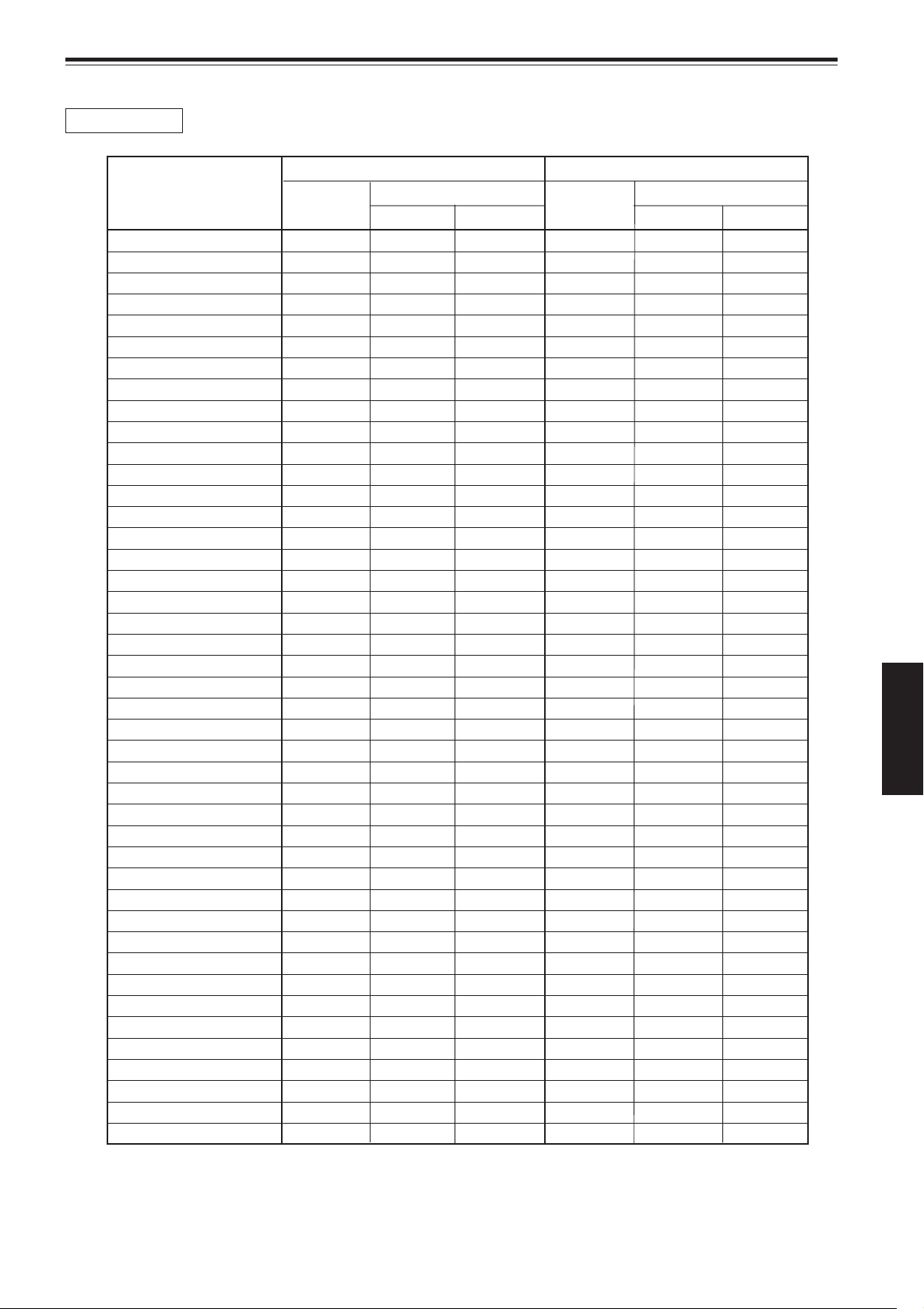
Appendix (Cont.)
GL-MQ1020ZG
Projection screen size For 4:3 aspect ratio screen For 16:9 aspect ratio screen
(Diagonal length) Width Projection distance Width Projection distance
73" (1.85) ———— ———— ———— 5.3 (1.62) 26.2 (8.0) ————
80" (2.03) ———— ———— ———— 5.8 (1.77) 28.5 (8.7) ————
87" (2.21) 5.8 (1.77) 28.5 (8.7) ———— ———— ———— ————
90" (2.29) 6.0 (1.83) 29.5 (9.0) ———— 6.5 (1.99) 32.1 (9.8) ————
100" (2.54) 6.7 (2.03) 32.8 (10.0) ———— 7.2 (2.21) 35.7 (10.9) ————
106" (2.69) ———— ———— ———— 7.7 (2.35) ———— 16.7 (5.1)
110" (2.79) 7.3 (2.24) 36.1 (11.0) ———— 8.0 (2.44) 39.3 (12.0) 17.4 (5.3)
116" (2.95) 7.7 (2.36) ———— 16.7 (5.1) ———— ———— ————
120" (3.05) 8.0 (2.44) 39.0 (11.9) 17.4 (5.3) 8.7 (2.66) 42.6 (13.0) 18.7 (5.7)
130" (3.30) 8.7 (2.64) 42.3 (12.9) 18.7 (5.7) 9.4 (2.88) 46.2 (14.1) 20.3 (6.2)
140" (3.56) 9.3 (2.84) 45.6 (13.9) 20.0 (6.1) 10.2 (3.10) 49.8 (15.2) 22.0 (6.7)
150" (3.81) 10.0 (3.05) 48.9 (14.9) 21.3 (6.5) 10.9 (3.32) 53.4 (16.3) 23.3 (7.1)
160" (4.06) 10.7 (3.25) 52.1 (15.9) 23.0 (7.0) 11.6 (3.54) 56.7 (17.3) 24.9 (7.6)
170" (4.32) 11.3 (3.45) 55.4 (16.9) 24.3 (7.4) 12.3 (3.76) 60.3 (18.4) 26.6 (8.1)
180" (4.57) 12.0 (3.66) 58.4 (17.8) 25.6 (7.8) 13.0 (3.98) 63.9 (19.5) 27.9 (8.5)
190" (4.83) 12.7 (3.86) 61.6 (18.8) 26.9 (8.2) 13.8 (4.21) 67.5 (20.6) 29.5 (9.0)
200" (5.08) 13.3 (4.06) 64.9 (19.8) 28.5 (8.7) 14.5 (4.43) 70.8 (21.6) 31.1 (9.5)
210" (5.33) 14.0 (4.27) 68.2 (20.8) 29.8 (9.1) 15.2 (4.65) 74.4 (22.7) 32.5 (9.9)
220" (5.59) 14.7 (4.47) 71.5 (21.8) 31.1 (9.5) 16.0 (4.87) 78.0 (23.8) 34.1 (10.4)
230" (5.84) 15.3 (4.67) 74.8 (22.8) 32.8 (10.0) 16.7 (5.09) 81.6 (24.9) 35.7 (10.9)
240" (6.10) 16.0 (4.88) 78.0 (23.8) 34.1 (10.4) 17.4 (5.31) 84.9 (25.9) 37.0 (11.3)
250" (6.35) 16.7 (5.08) 81.0 (24.7) 35.4 (10.8) 18.1 (5.53) 88.5 (27.0) 38.7 (11.8)
260" (6.60) 17.3 (5.28) 84.3 (25.7) 36.7 (11.2) 18.9 (5.76) 92.1 (28.1) 40.3 (12.3)
270" (6.86) 18.0 (5.49) 87.5 (26.7) 38.4 (11.7) 19.6 (5.98) 95.7 (29.2) 41.6 (12.7)
280" (7.11) 18.7 (5.69) 90.8 (27.7) 39.7 (12.1) 20.3 (6.20) 99.0 (30.2) 43.3 (13.2)
290" (7.37) 19.3 (5.89) 94.1 (28.7) 41.0 (12.5) 21.0 (6.42) 102.6 (31.3) 44.9 (13.7)
300" (7.62) 20.0 (6.10) 97.4 (29.7) 42.6 (13.0) 21.8 (6.64) 106.2 (32.4) 46.2 (14.1)
310" (7.87) 20.7 (6.30) 100.3 (30.6) 43.9 (13.4) 22.5 (6.86) 109.8 (33.5) 47.9 (14.6)
320" (8.13) 21.3 (6.50) 103.6 (31.6) 45.2 (13.8) 23.2 (7.08) 113.1 (34.5) 49.5 (15.1)
330" (8.38) 22.0 (6.71) 106.9 (32.6) 46.6 (14.2) 24.0 (7.31) 116.7 (35.6) 50.8 (15.5)
340" (8.64) 22.7 (6.91) 110.2 (33.6) 48.2 (14.7) 24.7 (7.53) 120.3 (36.7) 52.5 (16.0)
350" (8.89) 23.3 (7.11) 113.4 (34.6) 49.5 (15.1) 25.4 (7.75) 123.9 (37.8) 54.1 (16.5)
360" (9.14) 24.0 (7.32) 116.7 (35.6) 50.8 (15.5) 26.1 (7.97) 127.2 (38.8) 55.4 (16.9)
370" (9.40) 24.7 (7.52) 119.7 (36.5) 52.1 (15.9) 26.9 (8.19) 130.8 (39.9) 57.0 (17.4)
380" (9.65) 25.3 (7.72) 123.0 (37.5) 53.8 (16.4) 27.6 (8.41) 134.4 (41.0) 58.7 (17.9)
390" (9.91) 26.0 (7.92) 126.2 (38.5) 55.1 (16.8) 28.3 (8.63) 138.0 (42.1) 60.0 (18.3)
400" (10.16) 26.7 (8.13) 129.5 (39.5) 56.4 (17.2) 29.0 (8.86) 141.3 (43.1) 61.6 (18.8)
450" (11.43) 30.0 (9.14) 145.6 (44.4) 63.6 (19.4) 32.7 (9.96) 159.0 (48.5) 69.5 (21.2)
500" (12.70) 33.3 (10.16) 162.0 (49.4) 70.5 (21.5) 36.3 (11.07) 176.7 (53.9) 77.0 (23.5)
550" (13.97) 36.7 (11.18) 178.0 (54.3) 77.4 (23.6) 39.9 (12.18) 194.4 (59.3) 84.6 (25.8)
600" (15.24) 40.0 (12.19) 194.1 (59.2) 84.6 (25.8) 43.5 (13.28) 212.1 (64.7) 92.5 (28.2)
793" (20.14) ————— ————— ————— 57.6 (17.56) 280.3 (85.5) 122.0 (37.2)
867" (22.02) 57.8 (17.62) 280.3 (85.5) 122.0 (37.2) ————— ————— —————
unit: ft (m)
Tele end Wide end Tele end Wide end
ENGLISH
57
Page 60

Appendix (Cont.)
GL-MQ1023SZG
Projection screen size For 4:3 aspect ratio screen For 16:9 aspect ratio screen
(Diagonal length) Width Projection distance Width Projection distance
55" (1.40) ———— ———— ———— 4.0 (1.22) 28.2 (8.6) ————
60" (1.52) 4.0 (1.22) 28.2 (8.6) ———— 4.4 (1.33) 30.5 (9.3) ————
70" (1.78) 4.7 (1.42) 32.8 (10.0) ———— 5.1 (1.55) 35.7 (10.9) ————
73" (1.85) ———— ———— ———— 5.3 (1.62) ———— 16.4 (5.0)
80" (2.03) 5.3 (1.63) 37.4 (11.4) 16.4 (5.0) 5.8 (1.77) 40.7 (12.4) 18.0 (5.5)
90" (2.29) 6.0 (1.83) 42.0 (12.8) 18.4 (5.6) 6.5 (1.99) 45.6 (13.9) 20.0 (6.1)
100" (2.54) 6.7 (2.03) 46.6 (14.2) 20.3 (6.2) 7.2 (2.21) 50.8 (15.5) 22.3 (6.8)
110" (2.80) 7.3 (2.24) 51.1 (15.6) 22.6 (6.9) 8.0 (2.44) 55.7 (17.0) 24.6 (7.5)
120" (3.05) 8.0 (2.44) 55.7 (17.0) 24.6 (7.5) 8.7 (2.66) 60.7 (18.5) 26.6 (8.1)
130" (3.30) 8.7 (2.64) 60.3 (18.4) 26.6 (8.1) 9.4 (2.88) 65.9 (20.1) 28.9 (8.8)
140" (3.56) 9.3 (2.84) 64.9 (19.8) 28.5 (8.7) 10.2 (3.10) 70.8 (21.6) 31.1 (9.5)
150" (3.81) 10.0 (3.05) 69.5 (21.2) 30.5 (9.3) 10.9 (3.32) 75.7 (23.1) 33.1 (10.1)
160" (4.06) 10.7 (3.25) 74.1 (22.6) 32.5 (9.9) 11.6 (3.54) 80.7 (24.6) 35.4 (10.8)
170" (4.32) 11.3 (3.45) 78.7 (24.0) 34.4 (10.5) 12.3 (3.76) 85.9 (26.2) 37.7 (11.5)
180" (4.57) 12.0 (3.66) 83.3 (25.4) 36.4 (11.1) 13.0 (3.98) 90.8 (27.7) 39.7 (12.1)
190" (4.83) 12.7 (3.86) 87.9 (26.8) 38.4 (11.7) 13.8 (4.21) 95.7 (29.2) 42.0 (12.8)
200" (5.08) 13.3 (4.06) 92.5 (28.2) 40.3 (12.3) 14.5 (4.43) 101.0 (30.8) 43.9 (13.4)
210" (5.33) 14.0 (4.27) 97.0 (29.6) 42.3 (12.9) 15.2 (4.65) 105.9 (32.3) 46.2 (14.1)
220" (5.59) 14.7 (4.47) 101.6 (31.0) 44.3 (13.5) 16.0 (4.87) 110.8 (33.8) 48.5 (14.8)
230" (5.84) 15.3 (4.67) 106.2 (32.4) 46.2 (14.1) 16.7 (5.09) 115.7 (35.3) 50.5 (15.4)
240" (6.10) 16.0 (4.88) 110.8 (33.8) 48.5 (14.8) 17.4 (5.31) 121.0 (36.9) 52.8 (16.1)
250" (6.35) 16.7 (5.08) 115.4 (35.2) 50.5 (15.4) 18.1 (5.53) 125.9 (38.4) 55.1 (16.8)
260" (6.60) 17.3 (5.28) 120.0 (36.6) 52.5 (16.0) 18.9 (5.76) 130.8 (39.9) 57.0 (17.4)
270" (6.86) 18.0 (5.49) 124.6 (38.0) 54.4 (16.6) 19.6 (5.98) 136.1 (41.5) 59.3 (18.1)
280" (7.11) 18.7 (5.69) 129.2 (39.4) 56.4 (17.2) 20.3 (6.20) 141.0 (43.0) 61.6 (18.8)
290" (7.37) 19.3 (5.89) 133.8 (40.8) 58.4 (17.8) 21.0 (6.42) 145.9 (44.5) 63.6 (19.4)
300" (7.62) 20.0 (6.10) 138.4 (42.2) 60.3 (18.4) 21.8 (6.64) 150.8 (46.0) 65.9 (20.1)
310" (7.87) 20.7 (6.30) 143.0 (43.6) 62.3 (19.0) 22.5 (6.86) 156.1 (47.6) 67.9 (20.7)
320" (8.13) 21.3 (6.50) 147.5 (45.0) 64.3 (19.6) 23.2 (7.08) 161.0 (49.1) 70.2(21.4)
330" (8.38) 22.0 (6.71) 152.1 (46.4) 66.2 (20.2) 24.0 (7.31) 165.9 (50.6) 72.5 (22.1)
340" (8.64) 22.7 (6.91) 156.7 (47.8) 68.2 (20.8) 24.7 (7.53) 171.1 (52.2) 74.4 (22.7)
350" (8.89) 23.3 (7.11) 161.3 (49.2) 70.2 (21.4) 25.4 (7.75) 176.1 (53.7) 76.7 (23.4)
360" (9.14) 24.0 (7.32) 165.9 (50.6) 72.1 (22.0) 26.1 (7.97) 181.0 (55.2) 79.0 (24.1)
370" (9.40) 24.7 (7.52) 170.5 (52.0) 74.4 (22.7) 26.9 (8.19) 186.2 (56.8) 81.0 (24.7)
380" (9.65) 25.3 (7.72) 175.1 (53.4) 76.4 (23.3) 27.6 (8.41) 191.1 (58.3) 83.3 (25.4)
390" (9.91) 26.0 (7.92) 179.7 (54.8) 78.4 (23.9) 28.3 (8.63) 196.1 (59.8) 85.6 (26.1)
400" (10.16) 26.7 (8.13) 184.3 (56.2) 80.3 (24.5) 29.0 (8.86) 201.0 (61.3) 87.5 (26.7)
450" (11.43) 30.0 (9.14) 207.2 (63.2) 90.2 (27.5) 32.7 (9.96) 226.2 (69.0) 98.4 (30.0)
500" (12.70) 33.3 (10.16) 230.2 (70.2) 100.3 (30.6) 36.3 (11.07) 251.1 (76.6) 109.5 (33.4)
549" (13.94) ————— ————— ————— 39.8 (12.15) 275.7 (84.1) 120.0 (36.6)
550" (13.97) 36.7 (11.18) 253.1 (77.2) 110.2 (33.6) ————— ————— —————
600" (15.24) 40.0 (12.19) 276.1 (84.2) 120.0 (36.6) ————— ————— —————
unit: ft (m)
Tele end Wide end Tele end Wide end
58
Page 61

Specifications
Optical mechanism system
• Projection method 3D-ILA device, 1 lens, 3 primary color optical shutter method
• D-ILA device 1.3" measured diagonally (2 048 pixels ×1 536 pixels) × 3 (Total number of pixels : 9 437 184)
• Projecting lens GL-MQ1010G 1:1 fixed focus lens
(separately available) GL-MQ1015SG 1.5:1 fixed focus lens
GL-MQ1020ZG 2.1:1 to 4.9:1 zoom lens
GL-MQ1023SZG 3:1 to 7:1 zoom lens
• Screen size 60" to 300" [recommended] to 867" [maximum] measured diagonally (*with aspect ratio : 4 : 3)
• Light-source lamp 2.0 kW xenon lamp
Electrical system
• Resolution 2 048 dots × 1 536 dots (QXGA full resolution, during RGB input)
• Scanning frequency Horizontal frequency : 31.5 kHz to 135 kHz
Vertical frequency : 48 Hz to 120 Hz
(When HD signal is input, 24 Hz, 25 Hz, and 30 Hz are available.
For details, refer to page 44.)
Input / output
[RGB IN (RGB input)]
1-line, BNC × 5
Analog RGB signal
R : 0.7V(p-p), 75Ω
B : 0.7V(p-p), 75Ω
G : 0.7V(p-p), 75Ω
G on sync : 1V(p-p), 75Ω (negative sync)
Horizontal sync/composite sync signal (H/Cs)
H : 1V(p-p) to 5V(p-p), high impedance (positive/negative polarity)
Cs : 1V(p-p) to 5V(p-p), high impedance (positive/negative polarity)
Vertical sync signal (V)
V : 1V(p-p) to 5V(p-p), high impedance (positive/negative polarity)
* Some connected devices may not correspond to composite sync (Cs) or G on sync signal.
Horizontal frequency
: 31.5 kHz to 135 kHz
Vertical frequency
: 48 kHz to 120 kHz
Dot clock : 25 MHz to 280 MHz
[CONTROL]
• RS-232C IN : 1-line, D-sub 9-pin × 1
* RS-232C-interface specified control terminal for controlling this projector with a personal
computer.
ENGLISH
• RS-232C OUT : 1-line, D-sub 9-pin × 1
* RS-232C-interface specified control terminal for controlling other projectors with a personal
computer connected to this projector.
• REMOTE : 1-line, mini-jack × 1
(To be continued on the next page)
59
Page 62

Specifications (Cont.)
General
• Power requirements AC 200 V to 240 V, 50/60 Hz
• Power consumption 16 A (at 200V)
• Allowable operation temperature + 5°C to + 35°C (41°F to 95°F)
• Allowable relative humidity 90% or less (no condensation)
• Allowable storage temperature – 5°C to + 60°C (23°F to 140°F)
• Maximum outside dimensions Approx. (W)820 mm × (H)420 to 472 mm × (D)951 mm
5
/16˝ × 16-9/16˝ to 18-5/8˝ × 37-1/2˝)
(32-
(excluding protruding parts)
• Weight Approx. 92 kg (203 lbs.)
• Accessories (Refer to page 7.)
* Design and specifications are subject to change without notice.
* D-ILA devices are manufactured with a very high-precision technology, allowing 99.99% of the pixels to be effective. Only
0.01% or less of the pixels are missing or always illuminated.
* For easy understanding, pictures and illustrations are shown by being emphasized, omitted or composed, and may be more
or less different from actual products.
*TRADEMARKS
IBM ,IBM PC, and VGA are registered trademarks of International Business Machines Corporation. Macintosh is registered
trademarks of Apple Computer, Inc.
VESA is a trademark of the non-profit organization Video Electronics Standard Association.
All other product names mentioned herein are used for identification purposes only, and may be the trademarks or registered
trademarks of their respective companies.
60
Page 63

ZOOM
FOCUS
T
W
MENU
ENTER
EXIT
VIC SELECT
1
2
3
KEY STONE
OPERATE
HIDE
STAND BY
REMOTE
CONTROL
R
S
-232
C
O
U
T
R
S
-23
2C
IN
R
G
B
V
H/C
S
RGB Analog VIC
Specifications (Cont.)
3
5
6
9
4
8
2
1
7
Outside dimensions
■ To p
3
720 (28-
/8)
820 (32-5/16)
Unit: mm (inch)
30 (1-3/16)
838 (33)
30 (1-3/16)
■ Front
■ Side
820 (32-5/16)
720 (28-3/8)
)
16
/
9
) ~ 420 (16-
2
/
1
368 (14-
)
8
/
5
) ~ 472 (18-
16
/
9
420 (16-
42 (1-11/16)
18 (3/4)
660 (26)
φ
50 (φ 2)
Pin assignment (Specifications for terminals)
■ RS-232C terminal
951 (37-1/2)
838 (33)
42 (1-11/16)
18 (3/4)
)
8
/
3
)
59 (2-
16
/
1
)
230 (9-
8
/
3
ENGLISH
59 (2-
30 (1-3/16)30 (1-3/16)
Pin number Signal name
1 N/C
2RD
3TD
4 N/C
5 GND
Pin number Signal name
6 N/C
7 N/C
8 N/C
9 N/C
(To be continued on the next page)
61
Page 64
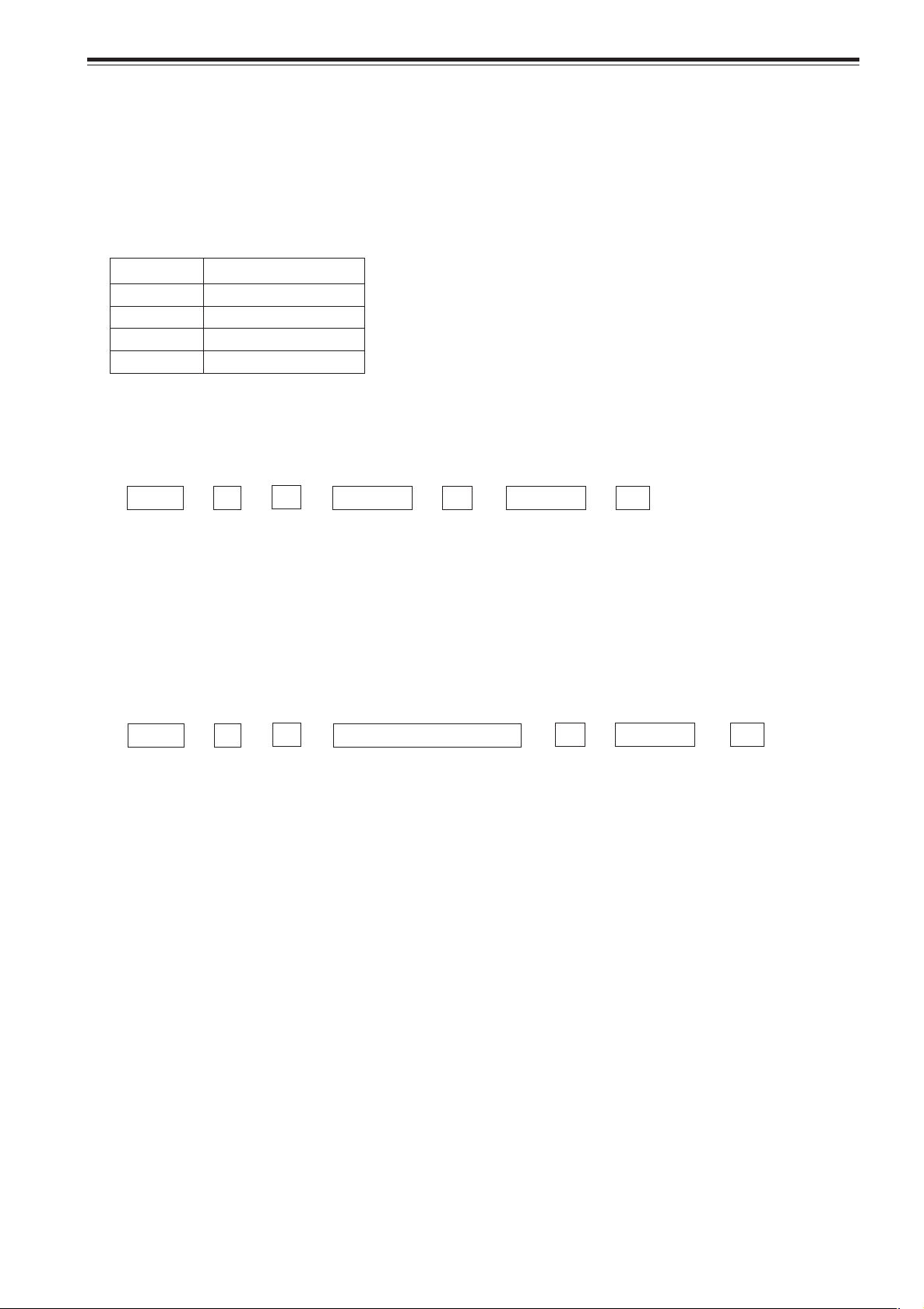
Specifications (Cont.)
RS-232C external control
By connecting a computer to the RS-232C IN terminal, you can control the projector. Use a reverse connection cable as the RS232C connection cable.
The commands to control the projector and the response data against the received commands are explained here.
For further information, please consult the dealer where you purchased your projector.
1. Communication Specifications
The communication specifications are as follows:
Baud rate 9600bps / 19200bps*
Data length 8 bits
Parity None
Stop bit 1 bit
Flow control None
* Initial value. To change the value, refer to page 46.
2. Command Format
2-1. Command data format (from the computer to the projector)
When sending a control command, use the following data format.
Header ID SP Command
Header : Designates the head of data and the kind of data
“!” (21h): Control command to the projector
“?” (3Fh): Query to the projector (Asking command)
ID : “1” (fixed)
SP : Designates the delimiter for ID, Command, and Parameter (20h)
CR : Designates the terminal of the data (0Dh)
* [ ] is not necessary for Asking command.
2-2. Response data format (from the projector to the computer)
Upon executing the received control command, the projector sends back the following response data to the computer.
Header ID SP Normal Termination Status SP Parameter CR
Header : Designates the head of data
“@” (40h): Fetches data from the projector
ID : “1” (fixed)
SP : Designates the delimiter for ID, Command, and Parameter (20h)
Normal Termination Status : “0” (30h)
CR : Designates the terminal of the data (0Dh)
SP Parameter
[
CR
]
62
Page 65

Specifications (Cont.)
2-3. Parameters used for the data format
The following three kinds of parameters are prepared for the control command and response data.
(1) Numeric value
Designates the 2-byte hexadecimal value with the sign as the 4-digit (byte) characters.
Designation allowable range : “8000” to “7FFF”
(2) ON/OFF
Designates the status (ON/OFF) of the projector, such as POWER and HIDE.
Character Hex. Meaning
“0” 30 OFF
“1” 31 ON
(3) Special parameters
Input switching parameters:
Character Hex. Meaning
“1” 30 VIC1
“2” 31 VIC2
“3” 33 VIC3
Operation mode parameters:
Character Hex. Meaning
“0000” 30h 30h 30h 30h Stand-by mode
“0001” 30h 30h 30h 31h Power-on mode
“0002” 30h 30h 30h 32h Cool-down mode
“0004” 30h 30h 30h 34h Warning mode
3. Control command table
The control commands that can be sent from the computer are as follows:
Function Command Asking Kind of data
Power ON ELSE Numeric Value ON/OFF Special Data
OPERATE U0F –– – ✓ –
HIDE U00 ✓ –– ✓ –
Right Left rev. U17 ✓ –– ✓ –
Keystone U40 ✓ – ✓ ––
Input U1A ✓ –– –VIC1, VIC2, VIC3
Operation mode Z03 ✓✓ ––Stand-by, Power-on,
Cool-down, Warning
* Keystone: Numeric value can range from “FF80” to “0080”
* Operation mode: Only Asking command is possible
ENGLISH
63
Page 66

Memorandum
Page 67

MANUEL D’INSTRUCTIONS
SUPER PROJECTEUR
DLA-QX1G
FRANÇAIS
Page 68

Merci d’avoir acheté ce projecteur. Avant de l’utiliser, lisez et respectez attentivement toutes les instructions pour profiter au maximum des capacités du projecteur.
PRÉCAUTIONS DE SÉCURITÉ
INFORMATIONS IMPORTANTES
AVERTISSEMENT :
POUR ÉVITER TOUT RISQUE D’INCENDIE OU D’ÉLECTROCUTION,
N’EXPOSEZ PAS CET APPAREIL À LA PLUIE OU À L’HUMIDITÉ.
AVERTISSEMENT:
CET APPAREIL DOIT ÊTRE MIS À LA TERRE.
ATTENTION :
Pour réduire les risques d’électrocution, ne retirez pas le couvercle. Référezvous à un personnel qualifié pour toute réparation.
INFORMATION SUR LES BRUITS MACHINE
(Allemagne uniquement)
Modifications de l’ordonnance 3 sur les bruits machine. GSGV du 18 janvier
1991: Le niveau de pression acoustique à la position de l’auditeur doit être
inférieure ou égale à 70 dB(A) conformément à la norme ISO 7779.
INFORMATIONS FCC (États-Unis uniquement)
ATTENTION: Tout changement ou modification non approuvés par JVC
peut annuler l’autorisation de l’utilisateur d’utiliser l’appareil.
REMARQUE: Cet appareil a été testé et trouvé conforme avec les limites
des appareils numériques de Classe A, conformément à la section 15 du
règlement FCC. Ces limites sont conçues pour offrir une protection
raisonnable contre les interférences nuisibles quand l’appareil est utilisé
dans un environnement commercial. Cet appareil produit, utilise et peut
émettre de l’énergie radiofréquence, il peut causer des interférences
nuisibles aux communications radio s’il n’est pas utilisé conformément au
mode d’emploi. L’utilisation de cet appareil dans une zone résidentielle peut
causer des interférences nuisibles et dans ce cas, l’utilisateur doit corriger
ces interférences à ses propres frais.
À propos de la fiche secteur (États-Unis uniquement)
Ce projecteur est muni d’une fiche à 3 broches avec mise à la terre
conforme au règlement FCC. Si vous ne pouvez pas insérer la fiche dans la
prise murale, contactez votre revendeur.
À propos de la brûlure du dispositif D-ILA
Ne projetez pas la même image fixe pendant longtemps ni ne projetez une
image vidéo anormalement brillante.
Ne projetez pas d’images vidéo avec une intensité ou un contraste élevé sur un
écran. L’image vidéo pourrait brûler le dispositif D-ILA.
Faites particulièrement attention lors de la projection d’images de jeux vidéo de
programmes informatiques. Il n’y a pas de problème avec les images de lecture
de cassettes vidéo.
2
Page 69

PRÉCAUTIONS DE SÉCURITÉ (suite)
IMPORTANTES MESURES DE SÉCURITÉ
L’énergie électrique peut remplir beaucoup de fonctions utiles. Cet appareil a été conçu et fabriqué pour assurer
votre propre sécurité. Mais UNE UTILISATION INCORRECTE PEUT ENTRAÎNER UN RISQUE POTENTIEL
D’ÉLECTROCUTION OU D’INCENDIE. Afin de ne pas annuler les dispositifs de sécurité incorporés dans cet
appareil, observez les règles fondamentales suivantes pour son installation, son utilisation et sa réparation. Veuillez
lire attentivement ces “IMPORTANTES MESURES DE SÉCURITÉ” avant d’utiliser l’appareil.
– Toutes les instructions de sécurité et de fonctionnement doivent être lues avant l’utilisation de l’appareil.
– Les instructions de sécurité et de fonctionnement doivent être conservées à titre d’information.
– Tous les avertissements sur l’appareil et dans le mode d’emploi doivent être compris et acceptés.
– Toutes les instructions de fonctionnement doivent être suivies.
– Débranchez cet appareil de la prise murale avant de le nettoyer. N’utilisez pas de nettoyant liquide ou aérosol. Utilisez un
chiffon humide pour le nettoyage.
– N’utilisez pas d’accessoires non recommandés par le fabricant de l’appareil car ils pourraient être dangereux.
– N’utilisez pas ce produit près de l’eau. Ne l’utilisez pas immédiatement après l’avoir déplacé d’une basse température à
une température élevée, car cela produit une condensation d’humidité qui peut entraîner un incendie, une électrocution ou
d’autres dangers.
– Ne placez pas cet appareil sur un chariot, un socle ou une table instable. L’appareil risquerait de tomber, de blesser
gravement un enfant ou un adulte et d’être sérieusement endommagé. L’appareil doit être monté conformément aux
instructions du fabricant et doit utiliser un support recommandé par le fabricant.
– Quand vous utilisez l’appareil sur un chariot, faites attention aux arrêts brusques, aux forces excessives et
aux surfaces accidentées qui pourraient causer un renversement de l’appareil, risquant de l’endommager ou
de blesser l’opérateur.
– Débranchez l’appareil de la prise secteur murale et contactez un réparateur qualifié dans les conditions
suivantes:
a) Quand le cordon ou la fiche d’alimentation secteur est endommagé.
b) Si un liquide a coulé ou si un objet est tombé à l’intérieur de l’appareil.
c) Si l’appareil a été exposé à la pluie ou à l’eau.
d) Si l’appareil ne fonctionne pas normalement en suivant les instructions de fonctionnement. Ajustez uniquement les
commandes couvertes par le mode d’emploi, car un ajustement incorrect des commandes peut endommager l’appareil
et demandera souvent beaucoup de temps à un technicien qualifié pour ramener l’appareil en état de fonctionnement
normal.
e) Si l’appareil est tombé ou a été endommagé de n’importe quelle autre façon.
f ) Quand l’appareil montre un changement évident dans ses performances – cela indique qu’il a besoin d’être réparé.
– Quand le remplacement de pièces est nécessaire, assurez-vous que le réparateur a utilisé les pièces de rechange
spécifiées par le fabricant ou possédant les mêmes caractéristiques que la pièce originale. Un remplacement non-autorisé
peut entraîner un incendie, une électrocution ou d’autres dangers.
– Après que cet appareil a subit une réparation ou un entretien, demandez au réparateur de réaliser les vérifications de
sécurité pour déterminer si l’appareil est en état de fonctionnement correct.
– L’appareil doit être placé à plus de trente centimètres de sources de chaleur comme un radiateur, un fourneau ou tout autre
appareil (y compris les amplificateurs) produisant de la chaleur.
– Lors de la connexion d’autres appareils comme des magnétoscopes ou des ordinateurs personnels, vous devez mettre cet
appareil hors tension pour vous protéger contre les chocs électriques.
– Ne placez pas de produits combustibles derrière le ventilateur de refroidissement. Par exemple, du tissu, du papier, des
allumettes, des bombes aérosols ou des briquets à gaz qui présentent des dangers particuliers s’ils sont chauffés.
– Ne regardez pas dans l’objectif de projection quand la lampe d’éclairage est allumée. Une exposition de vos yeux à une
forte lumière peut affaiblir votre vue.
FRANÇAIS
3
Page 70

PRÉCAUTIONS DE SÉCURITÉ (suite)
– Les fentes et les ouvertures du coffret sont nécessaires pour la ventilation. Elles assurent un fonctionnement sûr de l’appareil
et le protègent d’une surchauffe. Ces ouvertures ne doivent pas être bloquées ou recouv ertes. (Les ouvertures ne doivent
jamais être bloquées en plaçant l’appareil sur un lit, un divan, un tapis ou une surface similaire. Il ne doit pas être encastré
comme dans une bibliothèque ou un bâti sauf si une ventilation correcte e xiste et si les instructions du fabricant ont été
respectées.)
Pour une ventilation correcte, séparez l’appareil des autres appareils qui peuvent empêcher cette ventilation et conservez
un espacement de plus de 60 cm (23-5/8 pouces).
– Cet appareil doit être alimenté avec l’alimentation secteur indiquée sur l’étiquette. Si vous n’êtes pas sûr du type
d’alimentation secteur de votre maison, consultez le revendeur de l’appareil ou votre compagnie d’électricité.
– Cet appareil est équipé d’une fiche à trois broches. Elle ne peut être branchée que dans une prise secteur avec mise à la
terre. Si vous ne pouvez pas insérer la fiche dans la prise, contactez votre électricien afin qu’il installe une prise correcte.
N’allez pas à l’encontre du but de sécurité de la fiche avec mise à la terre.
– Les cordons d’alimentation doivent être acheminés de façon qu’ils ne soient pas écrasés ou coincés par des objets placés
sur eux ou contre eux. Faites particulièrement attention aux cordons à l’endroit des portes, des fiches et prises, et à
l’endroit où ils sortent de l’appareil.
– Pour une meilleure protection de l’appareil pendant un orage, ou quand il est laissé sans surveillance ou n’est pas utilisé
pendant une longue période de temps, débranchez-le de la prise secteur murale et déconnectez le système de câbles.
Cela évitera qu’il soit endommagé lors d’un orage ou par une surtension.
– Ne surchargez pas les prises murales, les cordons prolongateurs ou les prises de courant sur les autres appareils car cela
pourrait entraîner un risque d’incendie ou d’électrocution.
– N’insérez jamais d’objets d’aucune sorte à l’intérieur de cet appareil à travers les ouvertures car ils pourraient toucher des
points de tension dangereuse ou créer un court-circuit qui pourrait entraîner un incendie ou une électrocution. Ne versez
jamais de liquide d’aucune sorte dans l’appareil.
– N’essayez pas de réparer cet appareil vous-même car l’ouvrir ou retirer les couvercles peut vous exposer à des tensions
dangereuses ou à d’autres dangers. Référez-vous à un personnel qualifié pour toute réparation.
– Ne regardez pas à l’intérieur de cet appareil à travers les évents (trous de ventilation), etc. Ne regardez pas directement la
lampe d’éclairage en ouvrant le coffret pendant que celle-ci est allumée. La lampe d’éclairage émet aussi des rayons
ultraviolets et la lumière est si forte que votre vue pourrait être affaiblie.
– Du gaz xénon est contenu sous haute pression à l’intérieur de la lampe source de lumière (module lampe) de ce
projecteur. Si vous la laissez tomber, la frappez ou la jetez, il y a un risque d’explosion pouvant entraîner des blessures
personnelles. Faites très attention lors de la manipulation de la lampe. S’il y a quelque chose que vous ne comprenez pas,
contactez votre revendeur.
– Utilisez uniquement le cordon fourni conçu pour cet appareil afin d’éviter tout choc électrique.
La tension d’alimentation secteur de cet appareil est de 200 V à 240 V CA, le cordon d’alimentation fourni est conforme à
cette alimentation secteur. Utilisez uniquement le cordon d’alimentation désigné par nos revendeurs pour la sécurité et la
compatibilité électromagnétique (EMC).
Si l’appareil est utilisé avec une tension d’alimentation secteur différente, le cordon d’alimentation doit être changé.
Consultez votre revendeur.
*NE LAISSEZ PAS une personne non qualifiée installer l’appareil.
Demandez au revendeur d’installer l’appareil (par exemple, la fixation au plafond) car cela demande des
connaissances et des techniques spéciales.
Si l’installation est réalisée par une personne non qualifiée, cela pourrait entraîner des blessures personnelles ou
une électrocution.
4
Page 71

PRÉCAUTIONS DE SÉCURITÉ (suite)
CONNEXION DE L’ALIMENTATION
(Royaume-Uni uniquement)
AVERTISSEMENT
Ne coupez pas la fiche secteur de cet appareil.
Si la fiche secteur ne convient pas pour les prises murales de votre domicile ou si le câble est trop court pour atteindre la prise,
procurez-vous un cordon prolongateur ou un adaptateur approprié de sécurité, ou consultez votre revendeur.
Si néanmoins, la fiche secteur était coupée, retirez le fusible et débarrassez-vous de la fiche immédiatement afin d’éviter tout
risque d’électrocution en cas de connexion accidentelle au secteur.
Si vous devez fixer une nouvelle fiche, suivez les instructions données ci-dessous:
AVERTISSEMENT:
CET APPAREIL DOIT ÊTRE MIS À LA TERRE.
IMPORTANT:
Les fils du cordon d’alimentation secteur de cet appareil sont codés par couleur de la façon suivante:
Vert et jaune : Terre
Bleu : Neutre
Marron : Sous tension
Comme ces couleurs peuvent ne pas correspondre avec celles utilisées pour la fiche, procédez comme suit:
Le fil vert et jaune doit être connecté à la borne marquée
et jaune.
Le fil bleu doit être connecté à la borne marquée avec la lettre N ou la borne noire.
Le fil marron doit être connecté à la borne marquée avec la lettre L ou la borne rouge.
Lors du remplacement du fusible, assurez-vous d’utiliser un fusible de v aleur correcte et de type approuvé et remettez en place le
couvercle du compartiment à fusible.
EN CAS DE DOUTE—— CONSULTEZ UN TECHNICIEN COMPÉTENT.
ou avec la lettre E, ou une borne de terre, ou à la borne verte ou verte
Informations sur la fiche du cordon d’alimentation
Le cordon d’alimentation de ce projecteur ne possède pas de fiche secteur attachée. Nous vous
recommandons de choisir et d’attacher la fiche qui correspond à votre prise murale.
Utilisez une fiche 250V/20A.
Les fils à l’extrémité du cordon d’alimentation sont recouverts d’un isolant. Retirez l’isolant avant
d’attacher la fiche au cordon d’alimentation.
– Cet appareil est conforme avec les articles et les exigences de protection des Directives européennes correspondantes.
Cet appareil est conçu pour une utilisation professionnelle et peut être utilisé dans les environnements suivants.
• Environnement EMC (compatibilité électromagnétique) contrôlé (par exemple, un studio d’enregistrement ou de radio/
télévision), et environnement extérieur rural (loin des lignes de chemin de fer, des émetteurs, des lignes à haute tension,
etc.)
Afin de d’obtenir les meilleures performances possibles et pour une compatibilité électromagnétique, nous vous
recommandons d’utiliser des câbles qui ne dépassent pas les longueurs suivantes:
FRANÇAIS
AC INPUT Cordon d’alimentation 3 m
REMOTE Câble blindé 15 m
RGB ANALOG IN Câble blindé 3 m
HDTV ANALOG IN Câble blindé 5 m
RS232C CONTROL IN Câble blindé 3 m
RS232C CONTROL OUT Câble blindé 3 m
HD-SDI IN Câble blindé 5 m
• L’appel de courant de cet appareil est de 17,250 ampères.
5
Page 72

Table des matières
PRÉCAUTIONS DE SÉCURITÉ................. 2
Accessoires ............................................... 7
Commandes et fonctions ......................... 8
Face avant/ Face supérieure/ Face droite.............8
Côté gauche/ Côté arrière..................................... 9
Panneau de commande...................................... 10
Panneau de connexion .......................................12
Télécommande ................................................... 14
Touche de curseur (5/ ∞/ 2/ 3) / ENTER
(commande des menus) ................................ 16
Mise en place des piles....................................... 16
Installation du projecteur ....................... 17
Précautions pour l’installation ............................. 17
Ajustement de l’inclinaison du projecteur............ 19
Installation du projecteur par rapport à l’écran.... 20
Distance de projection et taille de l’écran ...........21
Fonction de décalage de l’objectif....................... 22
Plage et distance efficace
de la télécommande....................................... 24
Connexion de divers appareils .............. 25
Signaux pouvant être entrés dans le
projecteur....................................................... 25
Exemples de configuration du système .............. 26
Connexion d’appareils RVB ................................ 27
Connexion d’appareils analogiques HD.............. 28
Connexion d’appareils numériques HD ..............29
Connexion d’appareils qui commandent le
projecteur....................................................... 30
Connexion du cordon d’alimentation (fourni) ...... 31
Fonctionnement de base........................ 32
1. Mise sous tension ...........................................32
■ Mise hors tension............................................ 33
2. Sélection de la carte VIC à utiliser .................. 34
3. Ajustement de la taille de l’écran .................... 35
4. Ajustement de la mise au point .......................35
Pour utiliser les autres fonctions ......................... 36
■ Mise hors service de l’image vidéo (HIDE) .....36
■ Interruption de l’éclairage du projecteur quand
l’image vidéo est arrêtée (SHUTTER)....36
■ Suppression de la distorsion trapézoïdale de
l’image (KEYSTONE) ..........................37
■ Réglage de la valeur du décalage de l’objectif
(SHIFT) ................................................ 38
Utilisation des menus ............................. 39
■ Mode de menu sans signal .............................39
■ Mode de menu VIC RGB ................................ 40
■ Mode de menu VIC HDTV ou VIC HD-SDI .....41
Touches et commandes pour l’utilisation des
menus ............................................................ 42
Procédure d’utilisation des menus ......................43
Contenu des menus............................................ 44
■ Informations du menu principal....................... 44
■ Menu Qlt image............................................... 44
■ Menu Réglages...............................................44
■ Menu VIC (Menu VIC 1/2) ............................... 45
■ Menu Options.................................................. 46
■ Menu Language ..............................................46
■ Menu Temp.couleur.........................................46
■ Menu Sous-luminosité ....................................46
■ Menu Pos.affi. .................................................47
■ Menu Compensation & gain............................ 47
■ Menu Position menu ....................................... 47
■ Menu Keystone ...............................................47
■ Menu Utilisateur 1 ou 2 ...................................47
■ Menu Changement objectif .............................47
Nettoyage et remplacement des
filtres .................................................... 48
Remplacement de la lampe source de
lumière ................................................. 50
Guide de dépannage............................... 51
Messages d’avertissement..................... 53
Appendice................................................ 55
■ Relation entre la distance de projection et la
taille de l’écran.....................................55
· GL-MQ1010G .................................................55
· GL-MQ1015SG ...............................................56
· GL-MQ1020ZG ............................................... 57
· GL-MQ1023SZG............................................. 58
Spécifications.......................................... 59
6
Page 73

Accessoires
Les accessoires suivants sont fournis avec ce projecteur. Vérifiez s’ils sont bien tous présents. Si l’un de ces
accessoires manquait, veuillez contacter votre revendeur.
E
T
A
R
E
P
O
K
C
E
A
D
B
T
O
H
M
G
I
L
R
E
T
N
E
LO
C
K
U
N
L
O
C
K
U
EN
M
XIT
E
3
2VIC
1 VIC
VIC
S
CU
FO
T
T
IF
SH
M
O
ZO
T
W
L
A
T
N
I
G
I
O
D
M
O
O
Z
W
R
E
T
T
U
H
S
F
F
E
O
N
O
T
S
Y
E
K
T
I
N
U
L
O
R
T
N
O
C
E
T
O
M
E
R
G
1
X
Q
M
-
M
R
(Pour les États-Unis)
(Pour l’Europe)
Télécommande (RM-MQX1G) Pile sèche AA/R6 (×2)
(pour vérifier le fonctionnement)
Câble de télécommande
[environ 15 m (49,2 pouces)]
Capuchon de protection (×8)
(pour recouvrir les trous de vis)
Cordon d’alimentation
[environ 3,0 m (9,8 pouces)]
Informations sur les accessoires vendus séparément
• Objectif de projection
GL-MQ1010G Objectif à focale fixe 1 : 1
GL-MQ1015SG Objectif à focale fixe 1,5 : 1
GL-MQ1020ZG Objectif zoom 2,1 : 1 à 4,9 : 1
GL-MQ1023SZG Objectif zoom 3 : 1 à 7 : 1
• Carte d’interface vidéo (VIC)
PK-Q01HAG Une carte permettant l’addition de la fonction d’entrée de signaux HDTV
(signaux vidéo Y , P
PK-Q01HSDG Une carte permettant l’addition de la fonction d’entrée de signaux vidéo HD-
SDI au projecteur.
b et Pr) au projecteur.
ÇAIS
FRAN
7
Page 74
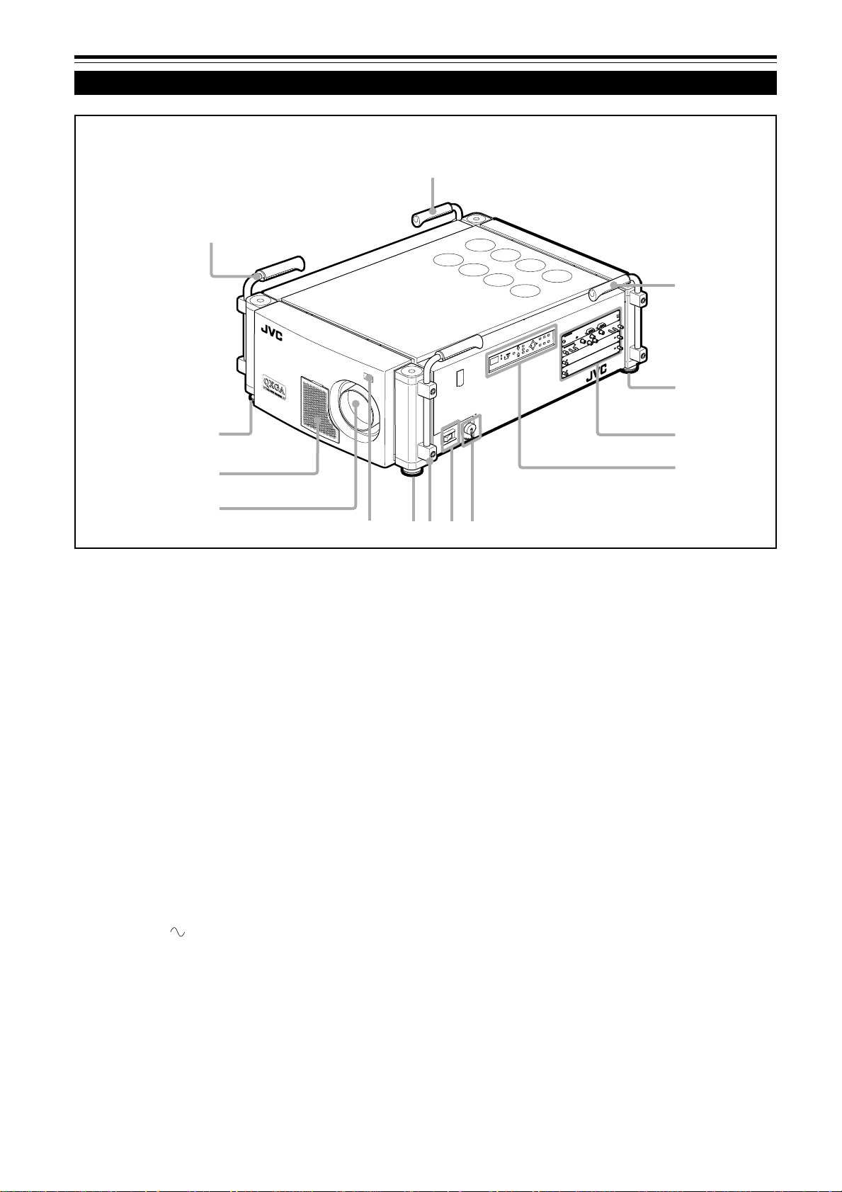
Commandes et fonctions
Face avant/ Face supérieure/ Face droite
1
1
1
N
I
C
2
3
2
S
R
T
U
O
C
2
3
2
S
R
E
T
O
M
L
E
O
R
R
T
T
N
R
O
U
C
N
E
M
S
U
C
O
F
M
O
O
Z
T
C
E
L
E
S
C
I
V
W
R
1
E
T
N
E
2
E
N
E
O
D
T
O
S
M
Y
E
K
T
I
X
E
Y
3
B
E
T
D
A
N
R
A
E
T
P
S
O
S
C
/
H
G
C
I
V
V
B
g
o
l
a
n
A
B
G
R
2
2
9
8
7
Poignées
1
Elles sont mises en place lors de l’expédition de l’usine.
Utilisez-les pour transporter ce projecteur. Vous pouvez
aussi les retirer si c’est nécessaire. Pour les détails,
référez-vous à “Pour retirer les poignées” à la page 9.
Pieds ajustables
2
Ils sont positionnés à la position la plus courte à
l’expédition de l’usine. Tournez les pieds pour mettre le
projecteur à niveau. L’ajustement peut être réalisé dans
une plage de ±3,5° verticalement et de ±4,5°
horizontalement.
Panneau de connexion
3
Pour les détails , référez-vous à “Panneau de connexion”
aux pages 12 et 13.
Panneau de commande
4
Pour les détails, référez-vous à “Panneau de commande”
aux pages 10 et 11.
Prise AC IN (entrée d’alimentation)
5
C’est la prise d’entrée d’alimentation où le cordon
d’alimentation fourni doit être connecté. Pour les détails,
référez-vous à “Connexion du cordon d’alimentation
(fourni)” à la page 31.
2
3
4
1
6
5
Interrupteur d’alimentation MAIN POWER
6
C’est l’interrupteur d’alimentation principale. Quand il est
mis sur la position ON, le projecteur entre en mode
d’attente et l’indicateur STAND BY s’allume sur le
panneau de commande.
ON [ ❙ ]: L’appareil est sous tension.
OFF [‡]: L’appareil est hors tension.
Capteur de télécommande
7
Pour utiliser la télécommande, dirigez-la v ers ce capteur.
Un capteur de télécommande supplémentaire se trouve
sur le panneau de commande du projecteur. La distance
de fonctionnement effective de la télécommande est
d’environ 10 m (32,8 pieds) à partir de chaque capteur.
La zone de fonctionnement effective est de 50°
horizontalement et 15° verticalement.
Monture de l’objectif
8
Fixez un objectif de projection vendu séparément sur cette
monture.
GL-MQ1010G Objectif à focale fixe 1 : 1
GL-MQ1015SG Objectif à focale fixe 1,5 : 1
GL-MQ1020ZG Objectif zoom 2,1 : 1 à 4,9 : 1
GL-MQ1023SZG Objectif zoom 3 : 1 à 7 : 1
Pour la fixation ou le remplacement de l’objectif , consulter
le revendeur qui a eff ectué l’installation et les ajustements
de votre projecteur.
8
Page 75

Commandes et fonctions (suite)
Côté gauche/ Côté arrière
Zone d’entrée d’air (filtre)
9, w
p
q
L’air entre par cette zone pour refroidir la lampe source
de lumière. Si cette zone est bloquée ou s’il y a quelque
chose qui empêche l’entrée d’air placé autour du
projecteur, la chaleur risque de s’accumuler à l’intérieur
de l’appareil et peut causer un incendie.
Pour les détails, référez-vous à “Précautions pour
l’installation” aux pages 17 et 18.
ATTENTION
• Faites attention car du papier, du tissu ou un coussin mou peut
être aspiré à l’intérieur s’il est placé à proximité. Ne bloquez pas la
zone d’entrée d’air sinon la chaleur risque de s’accumuler à
l’intérieur et risque de causer un incendie.
• Nettoyez le filtre périodiquement. L’accumulation de saleté sur le
filtre réduit l’effet de refroidissement, entraînant une accumulation
interne de chaleur qui peut causer un incendie ou un mauvais
fonctionnement.
Pour les détails, référez-vous à “Nettoyage et remplacement des
filtres” aux pages 48 et 49.
Évent de sortie d’air (pour l’alimentation de la lampe
e
source de lumière)
Cet évent évacue l’air chaud provenant du ventilateur de
refroidissement de l’alimentation de la lampe source de
lumière. Ce ventilateur continue de fonctionner aussi
longtemps que l’interrupteur MAIN POWER est sur la
position ON (sous tension).
w
e
Pour retirer les poignées
Retirez les deux vis fixant les poignées au
projecteur avec une clef hexagonale.
• Conservez les poignées et les vis pour une utilisation
future.
T
U
N
E
M
S
U
C
O
F
M
O
O
Z
T
C
E
L
E
S
C
I
V
W
R
E
1
T
N
E
2
E
N
E
O
D
T
O
S
M
Y
E
K
T
I
X
E
Y
3
B
E
T
D
A
N
R
A
E
T
P
S
O
Puis, fixez les capuchons de protection fournis pour
recouvrir les trous de vis.
T
U
N
E
M
S
U
C
O
F
M
O
O
Z
T
C
E
L
E
S
C
I
V
W
R
E
1
T
N
E
2
E
N
E
O
D
T
O
S
M
Y
E
K
T
I
X
E
Y
3
B
E
T
D
A
N
R
A
E
T
P
S
O
ÇAIS
FRAN
Évents de sortie d’air
p, q
Évents pour les ventilateurs de refroidissement par
lesquels sort l’air chaud.
9
Page 76

Commandes et fonctions (suite)
Panneau de commande
1234 5678
STAND BY
OPERATE
HIDE
KEY STONE
VIC SELECT
1
2
3
T
EXIT
MENU
ENTER
ZOOM
+
FOCUS
W
–
we9qp
Indicateur OPERATE
1
ON: Quand le projecteur est en fonctionnement
(projection)
Touche OPERATE
Quand le projecteur est en mode d’attente, appuyez sur
cette touche pendant plus d’une seconde pour mettre
l’appareil sous tension, et allumer l’indicateur OPERATE.
Appuyez de nouveau pour mettre le projecteur en mode
de refroidissement, puis en mode d’attente.
Pour les détails, référez-vous aux pages 32 et 33.
Mémo
Pendant les 20 premières secondes du mode de
refroidissement:
Si vous appuyez sur la touche OPERATE, le projecteur ne se met
pas sous tension.
Touche HIDE
2
Utilisez cette touche pour mettre hors service l’image
temporairement. Appuyez de nouveau pour rétablir
l’image.
Pour les détails, référez-vous à la page 36.
Touches KEYSTONE
3
Utilisez ces touches pour corriger la distorsion
trapézoïdale de l’image projetée.
Pour les détails, référez-vous à la page 37.
Touches VIC SELECT 1, 2 et 3
4
V ous pouv ez choisir la carte VIC (carte d’entrée vidéo)
installée sur le projecteur en appuyant sur une de ces
touches.
Pour les détails, référez-vous à la page 34.
Touche de curseur (5/∞/2/3)
5
Utilisez cette touche en mode de menu pour choisir un
élément ou pour régler une valeur.
Pour les détails, référez-vous aux pages 16 et 42.
Touche MENU
6
Utilisez cette touche pour entrer ou sortir du mode de
menu. Le menu apparaît ou disparaît de l’écran.
Pour les détails, référez-vous à “Procédure d’utilisation
des menus”, page 42.
Touches ZOOM T/W
7
Utilisez ces touches pour ajuster la taille d’écran
projetée. (Fonctionnent uniquement quand l’objectif fixé
au projecteur possède une fonction de zoom.)
T (Télé) : La taille d’écran projetée diminue.
W (Grand angle) :
La taille d’écran projetée augmente.
Pour les détails, référez-vous à la page 35.
Touches FOCUS +/–
8
Utilisez ces touches pour ajuster la mise au point de
l’image vidéo projetée.
+ : Le point de mise au point s’éloigne.
– : Le point de mise au point s’approche.
Pour les détails, référez-vous à la page 35.
Capteur de télécommande
9
Lors de l’utilisation de la télécommande, dirigez-la sur ce
capteur. Un capteur de télécommande supplémentaire
se trouve sur le panneau de commande du projecteur .
La distance de fonctionnement effective de la
télécommande est d’environ 10 m (32,8 pieds) à partir
de chaque capteur. La zone de commande effective est
comprise dans un angle de 50° horizontalement et de
15° verticalement.
Affichage du code d’état
p
Un nombre à 2 chiffres apparaît ici pour indiquer l’état du
projecteur. Référez-vous à la page de droite.
10
Page 77
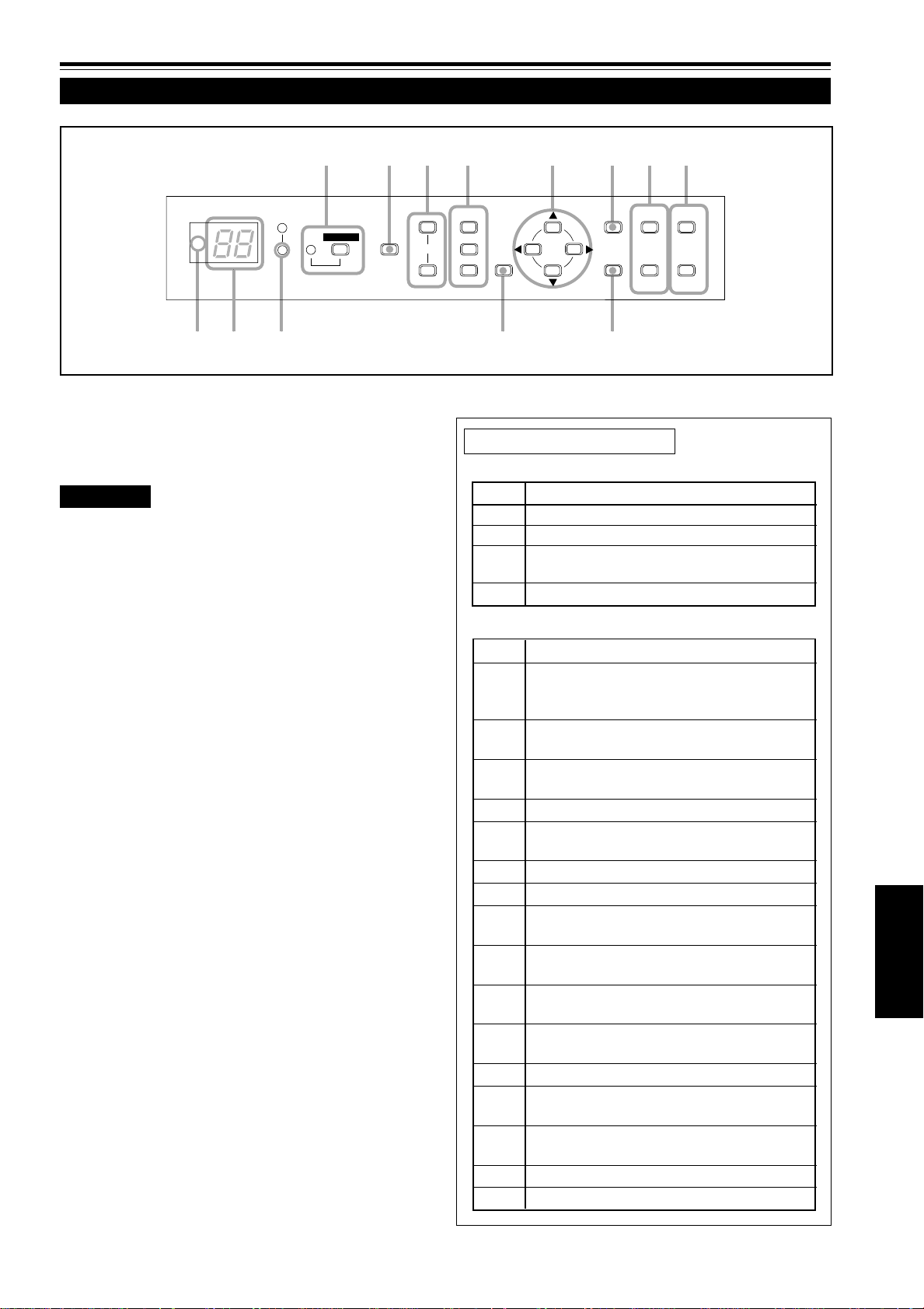
Commandes et fonctions (suite)
Panneau de commande (suite)
1234 5678
STAND BY
OPERATE
Indicateur STAND BY
q
Allumé : En mode d’attente.
Clignotant: En mode de refroidissement.
ATTENTION
• Le mode de refroidissement continue pendant environ 10 minutes.
Pendant les 20 premières secondes du mode de refroidissement,
le projecteur ne peut pas être remis sous tension. Pendant cette
période, l’indicateur STAND BY clignote et “07” apparaît sur
l’affichage du code d’état.
Ensuite,“07” change sur “06” sur l’affichage du code d’état, mais
l’indicateur STAND BY continue de clignoter et le ventilateur de
refroidissement continue de fonctionner pendant environ 10
minutes avant de s’arrêter.
Après le mode de refroidissement, le projecteur passe en mode
d’attente automatiquement (l’indicateur STAND BY ne clignote pas
mais reste allumé).
• Le but du mode de refroidissement est d’éviter aux pièces
intérieures d’être déformées ou cassées par la chaleur de la
lampe, de même que de prolonger la vie de la lampe.
Ne mettez pas l’appareil hors tension pendant le mode de
refroidissement. De plus, ne bloquez pas les évents de sortie d’air
pendant le mode de refroidissement.
• Le ventilateur de refroidissement pour l’alimentation de la lampe
source de lumière continue de fonctionner aussi longtemps que
l’interrupteur MAIN POWER est sur la position ON (sous tension).
Touche EXIT
w
Utilisez cette touche en mode de menu pour retourner
au menu précédent. Quand le menu principal est affiché,
cette touche fait disparaître le menu.
Pour les détails, référez-vous à la page 42.
Touche ENTER
e
Utilisez cette touche en mode de menu. Utilisez-la pour
afficher les menus hiérarchiques. Utilisez-la aussi quand
“ENTER” est affiché pour l’élément sur le menu.
Pour les détails, référez-vous aux pages 16 et 42.
HIDE
KEY STONE
T
VIC SELECT
1
2
3
EXIT
MENU
ENTER
ZOOM
+
FOCUS
W
–
we9qp
À propos des codes d’état
Indications normales
Code État
00 Le projecteur est en mode d’attente.
01 Le projecteur est dans un état normal.
06 Le projecteur est en mode de refroidissement
(possible de le remettre sous tension).
07 Le projecteur est en mode de refroidissement.
Indications d’erreur
Code État
02 Le panneau latéral est instable.
Température anormale de la lampe.
La lampe ne peut pas être allumée.
03 Le volet interne est fermé ou il y a un
problème avec le fonctionnement du volet.
04 Le projecteur est mis hors tension quand
aucun signal n’est entré.
10 La lampe s’éteint pendant la projection.
20 Problème avec l’alimentation de la lampe
source de lumière.
21 Problème avec l’alimentation du projecteur.
22 Problème avec l’alimentation du ventilateur .
23 Problème avec le refroidissement du
composant R.
24 Problème avec le refroidissement du
composant G.
25 Problème avec le refroidissement du
composant B.
30 Problème avec le ventilateur ou le capteur
de pression d’air.
40 Problème avec le microprocesseur.
80 La vie de la lampe approche de sa fin
(a dépassé 900 heures).
81 La vie de la lampe est presque terminée (a
dépassé 1000 heures).
82 Température anormale dans le projecteur.
83 Température anormale dans la pièce.
ÇAIS
FRAN
11
Page 78

Commandes et fonctions (suite)
Panneau de connexion
4
5
CONTROL
RGB Analog VIC
1
REMOTE
B
2
RS-232C OUT
V
6
3
RS-232C IN
G
H/C
R
S
Prise REMOTE (prise mini)
1
Cette prise est utilisée pour connecter directement la
télécommande au projecteur. Utilisez le câble de
télécommande fourni.
Prise RS-232C OUT (D-sub 9 broches)
2
C’est une prise d’interface RS-232C spécialisée. Quand
un autre projecteur DLA-QX1G est connecté à ce
projecteur, vous pouvez autoriser un ordinateur à
commander plusieurs projecteurs en même temps.
Pour les détails, consultez votre revendeur.
Prise RS-232C IN (D-sub 9 broches)
3
C’est une prise d’interface RS-232C spécialisée. Ce
projecteur peut être commandé par un ordinateur
connecté extérieurement.
Pour les détails, consultez votre revendeur.
DEL
4
Ce témoin DEL s’allume quand la carte VIC analogique
RVB est choisie.
12
Prises RGB IN (BNC x 5)
5
Ce sont des prises d’entrée vidéo multi-usage qui
permettent l’entrée des signaux suivants.
• Signaux analogiques RVB, signaux à sync. verticale (V)
et signaux à sync. horizontale (H) / signaux composites
(Cs). (Les appareils munis de prises de sortie
analogique RVB peuvent être connecté.)
*L’entrée de signaux de synchronisation extérieure est
détectée automatiquement. La détection des signaux
H/V ou Cs provoque la commutation automatique sur
la synchronisation extérieure. L’ordre de priorité est
H/V > Cs.
• Le côté supérieur de l’image peut apparaître courbé si
l’entrée du signal de synchronisation est sync.
composite ou sync sur G (vert). Dans ce cas, utilisez
des signaux de synchronisation séparés pour la sync.
verticale (V) et la sync. horizontale (H).
Fentes VIC (x 2)
6
Vous pouvez installer des cartes VIC optionnelles dans
ce projecteur en utilisant ces fentes. Les cartes VIC
suivantes sont disponibles.
• Carte VIC analogique HDTV
Cette carte VIC permet au projecteur de recevoir des
signaux d’entrée HDTV (Y, P
• Carte VIC HD-SDI
Cette carte VIC permet au projecteur de recevoir des
signaux d’entrée et de sortie HD-SDI. La prise de sortie
peut être utilisée comme prise de sortie en boucle pour
vérifier le signal d’entrée en connectant un moniteur
HD-SDI ou lors de l’utilisation de plusieurs projecteurs
en même temps.
Pour les détails, référez-vous à la page 13.
b et Pr) conventionnels.
Page 79

Panneau de connexion (suite)
À propos des cartes VIC optionnelles
Carte VIC analogique HDTV
DEL
Å
Ce témoin DEL s’allume quand la carte VIC
analogique HDTV est choisie.
Prise d’entrée Y , Pb, Pr (BNC x 3)
ı
Ce sont les prises d’entrée Y, Pb, Pr pour le
signal HD (SMPTE260M/274M/296M).
Carte VIC HD-SDI
DEL
Å
Ce témoin DEL s’allume quand la carte VIC HDSDI est choisie.
Prises d’entrée/sortie SDI (en boucle) (BNC x 2)
ı
Ce sont les prises d’entrée et sortie pour le signal
HD-SDI (SMPTE292M).
Comment installer les cartes VIC optionnelles
1
Retirez le panneau de la fente du
projecteur.
1) Retirez les deux vis du panneau de la fente, une à chaque
extrémité, d’une fente vide.
2) Retirez le panneau de la fente.
HDTV Analog VIC
HD-SDI VIC
Å
Å
N
O
C
RGB Analog VIC
Y
P
b
P
r
ı
ı
IN
E
T
O
M
L
E
O
R
R
T
B
OUT
N
I
C
2
3
2
-
S
R
T
U
O
C
2
3
2
-
S
R
R
S
H/C
G
Y
2
Installez la carte VIC.
1) Alignez les deux extrémités de la carte de circuits
imprimés avec les rainures de la fente et insérez la carte
VIC dans la fente.
2) Poussez la carte VIC à fond de façon que les deux
connecteurs de la surface intérieure soient bien branchés
dans les prises de la fente.
3
Vissez la carte VIC au projecteur.
Après avoir inséré la carte VIC dans la fente, vissez-la au
projecteur avec les deux vis attachées à la carte VIC.
Remarques
• Pour éviter que de la poussière entre à l’intérieur, ne
retirez pas le panneau de la fente de carte VIC non
utilisée.
• Lors de la remise en place du panneau de la fente,
positionnez-la avec la flèche dirigée vers le haut (se
trouvant aux deux extrémités du panneau) comme
illustré:
N
O
C
A
B
G
R
O
C
B
G
R
D
H
Flèche
N
I
C
2
3
2
-
S
R
T
U
O
C
2
3
2
-
S
R
E
T
O
M
L
E
O
R
R
T
C
I
V
g
o
l
a
n
L
O
REMOTE
R
T
N
IC
V
g
lo
a
n
A
C
I
V
g
o
l
a
n
A
V
T
R
S
C
/
H
G
Y
B
B
S
C
/
H
G
r
P
b
P
C
R
I
C
I
V
Y
V
g
g
o
l
o
l
a
a
n
n
A
Y
A
V
B
T
D
G
H
R
N
I
C
2
3
2
-
S
R
T
U
O
C
2
3
2
-
S
R
B
S
/C
H
G
Y
R
r
P
b
P
Y
ÇAIS
FRAN
13
Page 80

Commandes et fonctions (suite)
S
T
O
N
O
E
X
N
Télécommande
L
O
C
K
UN
LO
CK
t
1
OPERATE
LOCK UNLOCK
EXIT
VIC1 VIC2 VIC3
T
ZOOM
W
KEYSTONE
MODE
ENTER
MENU
SHIFT FOCUS
ON
SHUTTER
OFF
BACK
LIGHT
DIGITAL
ZOOM
W
T
E
y
r
e
w
q
2
3
4
5
6
7
8
Y
E
K
T
I
N
U
L
O
R
T
N
O
C
E
T
O
M
E
R
G
1
X
Q
M
-
M
R
RM-MQX1G REMOTE CONTROL UNIT
9
p
Émetteur de signaux de télécommande
1
Touche OPERATE
2
Quand le projecteur est en mode d’attente, appuyez sur
cette touche pendant plus d’une seconde pour mettre le
projecteur sous tension.
L’indicateur OPERATE s’allume.
• 30 secondes environ après la mise sous tension, une
image vidéo apparaît sur l’écran.
Quand le projecteur est sous tension, appuyez sur cette
touche pendant plus d’une seconde pour que le projecteur
entre en mode de refroidissement avant de passer en mode
d’attente.
Pour les détails, référez-vous à “ATTENTION”, page 11.
• La touche OPERATE
ne fonctionne pas pendant
environ 1 minute après que la lampe source de lumière
a été allumée. Utilisez cette touche une minute plus
tard environ.
Mémo
Pendant le mode de refroidissement (l’indicateur STAND BY
clignote):
Même si vous appuyez sur la touche OPERATE , le projecteur
ne se met pas sous tension. Attendez que le projecteur entre en
mode d’attente. (L’indicateur STAND BY reste allumé.)
Touche BACK LIGHT
3
Quand vous appuyez sur cette touche, toutes les touches
s’allument.
Si aucune touche n’est pressée pendant que les touches
sont éclairées, elles s’éteignent après plusieurs secondes.
14
Touche de curseur (5/∞/2/3) / ENTER
4
Lors de l’utilisation de la touche de curseur, appuyez
dans la direction 5/∞/2/3 où se trouve l’élément du
menu ou le réglage à choisir.
Pour l’utiliser comme touche ENTER, appuyez au centre
verts le bas.
La touche ENTER est utilisée en mode de menu. Utilisezla pour afficher les menus hiérarchiques. Utilisez-la aussi
quand “ENTER” est affiché pour l’élément sur le menu.
Pour les détails, référez-vous aux pages 16 et 42.
Touche MENU
5
Utilisez cette touche pour entrer ou sortir du mode de
menu. Le menu apparaît et disparaît de l’écran.
Pour les détails, référez-vous à la page 42.
Touches VIC 1, 2 et 3
6
Vous pouvez choisir la carte VIC (carte d’entrée vidéo)
souhaitée, installée dans le projecteur en appuyant sur
une de ces touches.
Pour les détails, référez-vous à la page 34.
Touches FOCUS +/–
7
Utilisez ces touches pour ajuster la mise au point de
l’image vidéo projetée.
+ : Le point de mise au point s’éloigne.
– : Le point de mise au point s’approche.
Pour les détails, référez-vous à la page 35.
Touches DIGITAL ZOOM T/W
8
Ne sont pas en service.
Page 81

Commandes et fonctions (suite)
S
T
O
N
O
E
X
N
Télécommande (suite)
LOCK
U
N
L
O
C
K
t
1
OPERATE
LOCK UNLOCK
EXIT
VIC1 VIC2 VIC3
T
ZOOM
W
KEYSTONE
MODE
ENTER
MENU
SHIFT FOCUS
ON
DIGITAL
SHUTTER
OFF
BACK
LIGHT
ZOOM
T
W
E
y
r
e
w
q
2
3
4
5
6
7
8
Y
E
K
R
T
N
O
C
E
T
O
M
E
R
G
1
X
Q
M
-
M
R
p
Touches SHUTTER ON/OFF
9
Utilisez ces touches pour commander le volet interne.
ON : Ferme le volet pour arrêter la projection.
OFF : Ouvre le volet pour commencer la projection.
Pour les détails, référez-vous à la page 36.
Prise de télécommande par fil
p
Pour utiliser la télécommande par fil, connectez le câble
de télécommande fourni entre cette prise et la prise REMOTE du panneau de connexion du projecteur.
Pour les détails, référez-vous à la page 24.
• L’émetteur de signaux de la télécommande ne fonctionne
pas quand le câble est connecté à cette prise.
Touches KEYSTONE
q
Utilisez ces touches pour corriger la distorsion
trapézoïdale de l’image projetée.
Pour les détails, référez-vous à la page 37.
Touches ZOOM T/W
w
Utilisez ces touches pour ajuster la taille d’écran
projetée. (Fonctionnent uniquement quand l’objectif fixé
au projecteur possède une fonction de zoom.)
T (Télé) : La taille d’écran projetée diminue.
W (Grand angle) :
La taille d’écran projetée augmente.
Pour les détails, référez-vous à la page 35.
9
T
I
N
U
L
O
RM-MQX1G REMOTE CONTROL UNIT
Touches SHIFT +/–
e
Utilisez ces touches pour ajuster la hauteur de l’écran de
projection quand plusieurs projecteurs sont utilisés dans
une configuration à empilement*.
(Elles fonctionnent uniquement quand l’objectif attaché
au projecteur possède une fonction de décalage.)
+:Déplace l’écran vers le haut.
– : Déplace l’écran vers le bas.
Pour les détails, référez-vous à la page 38.
Mémo
* Configuration à empilement:
Trois projecteurs maximum peuvent être empilés les uns sur les
autres (configuration à empilement). Cela vous permet de projeter
une image suffisamment lumineuse pour une grande salle ou un
endroit relativement lumineux.
Pour les détails, référez-vous à la page 20.
Touche EXIT
r
Utilisez cette touche pour retourner à l’écran précédent
lors de l’utilisation des menus.
Pour les détails, référez-vous à la page 43.
Commutateur LOCK Ô UNLOCK
t
Quand ce commutateur est dans la position “LOCK”, les
touches ZOOM T/W, SHIFT +/– et FOCUS +/– ne
fonctionnent pas. Quand un ajustement est nécessaire,
positionnez le commutateur sur “UNLOCK”.
ÇAIS
FRAN
Touche HIDE
y
Utilisez cette touche pour mettre hors service l’image
temporairement. Appuy ez de nouveau pour rétablir l’image .
Pour les détails, référez-vous à la page 36.
15
Page 82

Commandes et fonctions (suite)
K
Touche de curseur (5/∞/2/3) / ENTER (commande des menus)
La télécommande fournie avec ce projecteur possède une seule touche pour naviguer dans les menus. Appuyer sur la
touche de commande des menus trop fort peut entraîner une commande incorrecte. C’est pourquoi, faites quelques essais
pour vous familiariser au fonctionnement des touches avant de passer à une utilisation réelle.
E
T
A
R
E
P
O
ODE
M
2
1
BACK
LIGHT
2
2
L
O
C
K
U
N
L
O
C
ENTER
EXIT
2
MENU
2
VIC3
1 Lors de l’utilisation de la touche de curseur (5/∞/2/
3) / ENTER comme touche ENTER:
Appuyez au centre vers le bas quand un menu apparaît.
Quand
la touche fait apparaître le sous-menu correspondant.
apparaît sur l’élément choisi, appuyer sur
2 Lors de l’utilisation de la touche de curseur (5/∞/2/
3) / ENTER pour le déplacement du curseur:
Appuyez sur la touche dans une direction 5/∞/2/3.
Quand un menu apparaît, utilisez la touche pour choisir
un élément à ajuster ou réaliser un ajustement.
Mise en place des piles
Installez les piles dans la télécommande. Si la télécommande a commencé à fonctionner irrégulièrement, remplacez les piles.
Ouvrez le couvercle arrière.
1
Ouvrez le couvercle arrière dans la direction de la flèche.
Installez les piles.
2
Placez les deux piles (AA/R6-size) fournies dans la
télécommande de la façon montrée ci-dessous.
·
ª
ª
·
Refermez le couvercle arrière.
3
Insérez d’abord la griffe du couvercle arrière dans le
compartiment, puis fermez le couvercle arrière dans la
direction de la flèche.
Précautions pour l’utilisation des piles
Si les piles sont utilisées incorrectement, elles
risquent de se fissurer ou de fuir. Cela peut
entraîner un incendie, des brûlures, un mauvais
fonctionnement, ou tacher ou endommager
l’environnement.
Faites attention à ce qui suit:
• N’utilisez pas en même temps une pile neuve et une
vieille pile.
• N’utilisez pas en même temps différents types de piles
car elles ont des caractéristiques différentes.
• Placez les piles de façon qu’elles respectent les
polarités indiquées: (+) à (+) et (–) à (–).
• Assurez-vous de mettre la borne moins (–) en premier
pour éviter les court-circuits.
• Utilisez uniquement les piles indiquées.
• Retirez les piles si elles ne sont pas utilisées pendant
une longue période de temps.
• Quand les piles sont usées, remplacez-les
immédiatement. Sinon, elles pourraient fuir, ou un
mauvais fonctionnement pourrait se produire à cause
de la fuite d’électrolyte. Si le liquide qui fuit des piles
entre en contact avec la peau, essuyez-le avec un
chiffon, sinon la peau pourrait devenir rêche.
• Ne mettez pas les piles dans le feu ni n’essayez de les
recharger.
• Les piles ont une durée de vie de six mois à un an lors
d’une utilisation normale. Mais les piles fournies sont
pour vérifier le fonctionnement et risquent de ne pas
durer si longtemps. Quand la télécommande
commence à ne pas fonctionnement correctement,
remplacez les piles par des neuves.
16
Page 83

Installation du projecteur
Précautions pour l’installation
ATTENTION
• Puisque le projecteur pèse environ 92 kg (203 livres), assurez-vous de le faire soulever ou
déplacer par 4 personnes ou plus; sinon, le projecteur pourrait tomber et blesser quelqu’un et/
ou être endommagé.
N’installez pas le projecteur dans les endroits suivants:
• Où il y a beaucoup d’eau, d’humidité ou de poussière.
• Où le projecteur peut être sujet à de la fumée grasse ou à de la fumée de cigarette.
• Sur une surface molle telle qu’un tapis ou un coussin.
• Où le projecteur peut être sujet à la lumière directe du soleil.
• Où la température est élevée ou l’humidité faible.
Plage de température de fonctionnement admissible: + 5°C à + 35°C (41°F à 95°F)
Plage d’humidité relative admissible: 20% à 80% (sans condensation)
Plage de température de stockage admissible: –10°C à +60°C (14°F à 140°F)
■ Lors de l’installation du projecteur, respectez les points suivants:
• N’utilisez pas le projecteur couché sur le côté ou placé à l’envers.
Le projecteur ne peut pas être utilisé couché sur le côté ou placé à l’envers; sinon, il pourrait mal fonctionner.
• Utilisez le projecteur à l’intérieur de la plage des angles d’installation permis.
Évitez d’utiliser le projecteur av ec une inclinaison de plus de 5° de droite à gauche ou de gauche à droite, et de 25° d’avant en
arrière ou d’arrière en av ant; sinon, cela pourrait entraîner une v ariation des couleurs ou réduire la durée de vie de la lampe.
• Ne bloquez pas les évents de sortie d’air.
N’utilisez pas de couverture recouvrant le projecteur et bloquant les évents de sortie d’air. Laissez suffisamment
d’espace autour du projecteur. Si le projecteur est enfermé dans un espace aux dimensions indiquées ci-dessous,
utilisez une climatisation pour que la température à l’intérieur de l’espace soit égale à la température extérieure.
Espace minimum admissible requis
Vue avant
600 mm (23-5/8 pouces)
Vue latérale droite
305 mm (12 pouces)
305 mm (12 pouces)
T
MENU
VIC SELECT
STAND BY
1
HIDE
OPERATE
ZOOM
FOCUS
23KEY STONE
W
ENTER
EXIT
CONTROL
RGB Analog VIC
600 mm (23-5/8 pouces)
ÇAIS
FRAN
REMOTE
RS-232C IN
RS-232C OUT
R
G
B
S
H/C
Y
600 mm (23-5/8 pouces)
17
Page 84
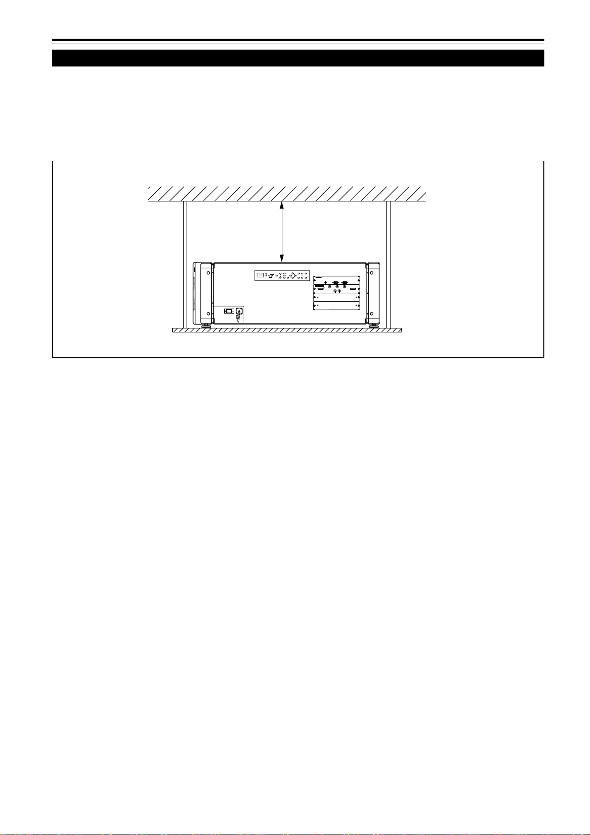
Installation du projecteur (suite)
Précautions pour l’installation (suite)
■ Respectez les points suivants lors de la suspension du projecteur au plafond
• Pour éviter que le projecteur ne tombe ou se renverse, il est recommandé de fixer le projecteur à son support avec des
boulons.
• Lors du montage du projecteur au plafond, installez d’abord une tablette spéciale et placez le projecteur solidement
dessus. Pour des raisons de sécurité et d’entretien, un dispositif permettant de soulever et de descendre le projecteur
de la tablette est nécessaire pour son entretien.
305 mm (12 pouces)
ou plus
T
MENU
VIC SELECT
STAND BY
1
HIDE
OPERATE
ZOOM
FOCUS
23KEY STONE
CONTROL
W
ENTER
EXIT
REMOTE
RS-232C IN
RS-232C OUT
RGB Analog VIC
R
G
B
S
H/C
Y
18
Page 85

Installation du projecteur (suite)
Ajustement de l’inclinaison du projecteur
L’angle vertical et le niveau du projecteur peuvent être ajustés avec les pieds ajustables situés sous l’appareil.
■ Ajustement de l’angle vertical du projecteur
Soulevez le projecteur, tournez le pied ajustable avant et ajustez l’angle dans une plage de 0° à 3,5°.
+3,5
Étendre Réduire
■ Niveau du projecteur
Soulevez le projecteur, tournez le pied ajustable et ajustez l’angle horizontal jusqu’à ce que l’appareil soit à niveau.
+4,5˚
–4,5˚
Étendre Réduire
ÇAIS
FRAN
19
Page 86

Installation du projecteur (suite)
Installation du projecteur par rapport à l’écran
Le projecteur doit être placé de façon que la ligne centrale de l’objectif soit à angle droit avec l’écran comme montré sur les
illustrations suivantes.
■ Projection normale
■ Projection inclinée
3,55°
■ Projection à travers une vitre
T
E
U
N
M
E
T
C
S
E
L
C
V
I
D
N
Y
S
B
T
A
1
E
D
I
H
E
P
T
E
A
R
O
O
O
M
Z
S
U
F
C
O
2
S
E
T
N
O
E
K
Y
C
O
N
O
T
R
L
3
W
E
R
T
N
E
T
X
I
E
N
I
2
C
-
2
3
R
S
R
M
E
O
T
E
U
T
O
3
2
C
-
2
R
S
RGB Analog VIC
R
G
B
S
H/C
Y
T
E
U
N
M
T
C
E
E
L
S
I
C
V
D
Y
N
B
A
S
T
1
E
D
I
H
E
T
A
E
R
O
P
M
O
O
Z
S
U
C
O
F
2
E
O
N
T
S
Y
E
K
C
O
N
T
R
O
L
3
W
R
E
T
N
E
I
T
E
X
N
I
2
C
-
2
3
R
S
R
M
E
O
T
E
U
T
O
2
C
-
2
3
R
S
RGB Analog VIC
R
G
B
H/C
S
Y
• La luminosité de l’image vidéo est réduite lors de la
projection à travers une vitre. Il n’est pas recommandé
de projeter une image vidéo à travers plusieurs vitres.
• Même si le projecteur n’est pas installé à angle droit
T
U
N
E
M
T
C
E
L
E
S
C
I
V
1
S
U
C
O
F
Y
N
I
M
B
O
D
O
C
N
Z
2
A
T
3
L
S
2
-
O
S
R
R
T
N
O
C
T
U
O
C
2
3
E
2
D
I
-
H
S
R
E
T
A
R
E
P
E
O
T
O
2
M
E
E
R
N
O
T
S
Y
E
K
W
R
E
T
N
E
3
T
I
X
E
C
I
V
g
o
l
a
n
A
B
G
R
B
G
R
S
C
/
H
Y
avec la vitre, vous pouvez profiter de la projection à
travers la vitre. Dans ce cas, ajustez la position du
projecteur et/ou de la vitre afin d’éviter toute réflexion
diffuse.
■ Projection en utilisant une configuration à
empilement
Trois projecteurs maximum peuvent être empilés les uns
sur les autres (configuration à empilement).
Utiliser deux ou trois projecteurs permet d’obtenir une
image plus lumineuse. Cela permet de projeter une
image suffisamment lumineuse dans une grande salle ou
un endroit relativement lumineux.
ATTENTION
• Pour éviter tout dommage au projecteur pendant le transport, une
broche de verrouillage centrale du décalage a été utilisée pour
fixer le mécanisme de l’objectif à l’expédition de l’usine. Si
l’objectif ne se déplace pas vers le haut ou le bas lors de
l’ajustement du décalage de l’objectif à l’aide des touches de la
télécommande ou du menu de réglage, c’est que la broche de
verrouillage central du décalage n’a peut-être pas été retirée.
Dans ce cas, consultez votre revendeur ou un centre de service.
20
T
E
U
N
M
T
C
E
E
L
C
S
I
V
Y
B
D
N
A
T
S
1
I
E
D
H
E
T
A
R
P
E
O
O
M
O
Z
S
U
O
C
F
2
E
N
O
S
Y
T
E
K
C
O
N
T
R
O
L
3
W
R
E
E
T
N
T
X
I
E
N
I
C
2
2
3
-
R
S
E
M
R
O
T
E
OUT
C
2
3
2
-
R
S
RGB Analog VIC
R
G
B
S
H/C
Y
T
U
N
E
M
T
C
E
L
E
S
C
I
V
Y
B
D
N
A
T
S
1
E
I
D
H
E
T
A
R
E
P
O
M
O
O
Z
S
U
C
O
F
2
E
N
O
T
S
Y
E
K
C
O
N
O
T
R
L
3
W
R
E
T
N
E
T
I
X
E
I
N
C
2
3
2
-
R
S
R
E
M
O
T
E
OUT
C
2
3
2
-
R
S
RGB Analog VIC
R
G
B
S
H/C
Y
• Lors de l’utilisation de la configuration à empilement,
installez d’abord le cadre spécialement conçu pour la
configuration à empilement. Décidez l’emplacement
d’installation dans un endroit stable et avec une bonne
ventilation.
• Pour la configuration à empilement, vous devez utiliser
des objectifs munis de la fonction de décalage.
Page 87

Installation du projecteur (suite)
Distance de projection et taille de l’écran
La plage des distances de projection pour lesquels la mise au point est possible dépend de l’objectif (non fourni) utilisé.
Quand le format de l’écran est 4:3, la plage est comme suit et vous devez installer le projecteur à l’intérieur de cette plage.
Type d’objectif Distance de projection approximative
GL-MQ1010G 1, 2 m (3,9 pieds) à 7,9 m (25,9 pieds)
GL-MQ1015SG 1, 7 m (5,6 pieds) à 12,3 m (40,3 pieds)
GL-MQ1020ZG 8, 0 m (26,2 pieds) à 85,5 m (280,3 pieds)
GL-MQ1023SZG 8, 6 m (28,2 pieds) à 84,2 m (276,1 pieds)
La valeur de la distance de projection est un guide (référence). La taille de l’image projetée peut varier en fonction des
tolérances de fabrication et de l’objectif de projection.
Modification de l’écran de projection en
fonction du format d’image
Écran avec un format
d’image de 4:3
Écran avec un format d’image de 16:9
• Pour la relation détaillée entre la distance de projection et la taille de l’écran de projection, référez-vous à l’appendice. La
relation pour les formats 4:3 et 16:9 y est donnée.
• Lors de l’ajustement de la taille de l’écran, utilisez une image au format 4:3. (Les images au format 16:9 sont projetées sur
la base de la largeur des images au format 4:3.)
• La longueur diagonale d’un écran au format d’image 16:9 est d’environ 91,8%, celle d’un écran au format d’image 4:3.
Cette valeur est un guide uniquement (référence).
• Si la distorsion trapézoïdale est ajustée, l’écran projeté devient plus petit.
■ Objectifs optionnels
Ce projecteur ne comprend pas d’objectif. Vous pouvez choisir un des objectifs optionnels pour ajuster la distance de
projection. Veuillez consulter votre revendeur pour l’achat et l’installation d’un objectif.
Modèle d’objectif Fonction
GL-MQ1010G Objectif à mise au point motorisée pour projection arrière et courte distance focale (rapport
d’agrandissement de 1:1), influence 0%.
GL-MQ1015SG Objectif à mise au point motorisée et courte distance focale (rapport d’agrandissement de
1,5:1), avec fonction de décalage vertical manuel, influence de 0% à ±50%.
GL-MQ1020ZG Objectif à mise au point/zoom motorisé et longue distance focale (rapport d’agrandissement
de 2,1:1 à 4,9:1), influence 0%.
GL-MQ1023SZG Objectif à mise au point/zoom motorisé et longue distance focale (rapport d’agrandissement
de 3:1 à 7:1), avec fonction de décalage vertical manuel, influence de 0% à ±50%.
ÇAIS
FRAN
21
Page 88

Installation du projecteur (suite)
Fonction de décalage de l’objectif
Certains des objectifs vendus séparément possèdent une fonction de décalage de l’objectif.
Pour les objectifs avec une fonction de décalage: Si le décalage de l’objectif est réglé sur 50%, installez le projecteur de
façon que le côté inférieur de l’écran de projection soit à la même hauteur que le centre de l’objectif. Quand le décalage de
l’objectif est réglé sur –50%, installez le projecteur de façon que le côté supérieur de l’écran de projection soit à la même
hauteur que le centre de l’objectif.
Pour les objectifs sans fonction de décalage de l’objectif ou quand le décalage de l’objectif est réglé sur 0%:
Installez le projecteur de façon que le centre de l’écran de projection soit à la même hauteur que le centre de l’objectif.
Pour les objectifs avec une fonction de décalage de l’objectif
Quand le décalage de l’objectif est réglé sur 50%
90°
90° 90°
Ligne centrale de l’objectif
Ligne centrale de l’objectif
90° 90° 90°
Ligne centrale de l’objectif
T
M
N
E
U
C
I
V
E
S
L
C
E
T
S
T
A
D
N
B
Y
1
H
I
D
E
O
E
P
R
A
T
E
Z
O
O
M
F
O
C
U
S
2
K
Y
E
S
T
O
N
E
C
O
N
O
T
R
L
3
W
N
E
T
E
R
X
E
T
I
R
S
-
2
3
2
C
I
N
E
T
O
M
E
R
R
S-2
3
2
C
O
U
T
RGB Analog VIC
R
G
B
S
H/C
Y
Quand le décalage de l’objectif est réglé sur –50%
T
M
N
E
U
I
V
C
E
S
L
C
E
T
S
T
A
N
D
B
Y
1
H
D
I
E
O
E
P
R
A
T
E
Z
O
O
M
F
O
C
U
S
2
K
E
S
Y
T
O
N
E
C
O
N
O
T
R
L
3
W
E
N
T
R
E
E
I
X
T
R
S-2
3
2
C
N
I
E
T
O
M
E
R
R
S
-
2
3
2
C
O
U
T
RGB Analog VIC
R
G
B
S
H/C
Y
Pour les objectifs sans fonction de décalage de l’objecfif
ou quand le décalage de l’objectif est réglé sur 0%
T
M
E
N
U
V
C
I
S
E
L
E
C
T
S
T
A
N
D
B
90°90°90°
Y
1
H
I
D
E
O
P
E
R
A
T
E
Z
O
O
M
F
O
C
U
S
2
K
E
Y
S
T
O
E
N
C
O
N
T
R
O
L
3
W
E
N
T
E
R
E
X
I
T
R
S
-
2
3
2
C
N
I
E
T
O
M
E
R
R
S
-
2
3
2
C
O
U
T
RGB Analog VIC
R
G
B
H/C
S
Y
• Lors de l’utilisation d’un objectif avec la fonction de décalage, vous pouvez ajuster l’image projetée verticalement en
utilisant le menu de réglage ou les touches SHIFT +/– sur la télécommande.
• Lors de l’utilisation de plusieurs projecteurs dans une configuration à empilement (les uns sur les autres), réalisez un
ajustement de façon que l’image de projection de chaque projecteur se superpose exactement en utilisant la fonction de
décalage de l’objectif. Si un ajustement horizontal est nécessaire, consultez votre revendeur.
• Pour les procédures d’ajustement détaillées, référez-vous aux pages 38 et 46.
• Pour la valeur maximale du décalage, référez-vous à “Valeur maximale du décalage” à la page 23. (Si l’objectif doit être
ajusté avec un angle horizontal, consultez votre revendeur.)
22
Page 89

Installation du projecteur (suite)
Fonction de décalage de l’objectif (suite)
Écr an après décalage
(x): 100%
Valeur maximale du décalage
La valeur maximale du décalage est limitée par la valeur du
décalage horizontal réalisé.
La valeur du décalage est définie comme suit:
Quand la largeur de l’écran est comptée comme 1, le décalage
horizontal est défini par le rapport (%) à la largeur de l’écran,
tandis que quand la hauteur de l’écran est comptée comme 1,
le décalage vertical est défini par le rapport (%) à la hauteur de
l’écran.
Py(%)
Taille verticale de
l’écran
(y): 100%
Écran sans décalage (0)
Taille horizontale de l’écran
Tableau des relations pour la valeur maximale du décalage (rapport d’image 4 : 3)
Py(%) Px(%) Py(%) Px(%) Py(%) Px(%) Py(%) Px(%) Py(%) Px(%)
0,0 32,0 10,0 28,1 20,0 23,3 30,0 17,3 40,0 9,7
1,0 31,6 11,0 27,7 21,0 22,7 31,0 16,6 41,0 8,9
2,0 31,3 12,0 27,2 22,0 22,2 32,0 15,9 42,0 8,0
3,0 30,9 13,0 26,8 23,0 21,6 33,0 15,2 43,0 7,1
4,0 30,5 14,0 26,3 24,0 21,0 34,0 14,5 44,0 6,2
5,0 30,1 15,0 25,8 25,0 20,4 35,0 13,7 45,0 5,2
6,0 29,8 16,0 25,3 26,0 19,8 36,0 13,0 46,0 4,2
7,0 29,4 17,0 24,8 27,0 19,2 37,0 12,2 47,0 3,2
8,0 28,9 18,0 24,3 28,0 18,6 38,0 11,4 48,0 2,2
9,0 28,5 19,0 23,8 29,0 17,9 39,0 10,6 49,0 1,2
50,0 0,0
Px
(%)
Tableau des relations pour la valeur maximale du décalage (rapport d’image 16 : 9)
Py(%) Px(%) Py(%) Px(%) Py(%) Px(%) Py(%) Px(%) Py(%) Px(%)
0,0 32,0 10,0 29,2 20,0 25,8 30,0 21,9 40,0 17,3
1,0 31,7 11,0 28,8 21,0 25,1 31,0 21,5 41,0 16,8
2,0 31,4 12,0 28,5 22,0 24,7 32,0 21,0 42,0 16,2
3,0 31,2 13,0 28,2 23,0 24,3 33,0 20,6 43,0 15,7
4,0 30,9 14,0 27,9 24,0 23,9 34,0 20,1 44,0 15,2
5,0 30,6 15,0 27,6 25,0 23,9 35,0 19,7 45,0 14,6
6,0 30,3 16,0 27,2 26,0 23,5 36,0 19,2 46,0 14,1
7,0 30,0 17,0 26,9 27,0 23,1 37,0 18,7 47,0 13,5
8,0 29,8 18,0 26,5 28,0 22,7 38,0 18,3 48,0 13,0
9,0 29,5 19,0 26,2 29,0 22,3 39,0 17,8 49,0 12,4
Py(%) Px(%) Py(%) Px(%)
50,0 11,8 60,0 5,2
51,0 11,2 61,0 4,5
52,0 10,6 62,0 3,7
53,0 10,0 63,0 3,0
54,0 9,3 64,0 2,2
55,0 8,7 65,0 1,4
56,0 8,0 66,7 0,0
57,0 7,3
58,0 6,6
59,0 5,9
ÇAIS
FRAN
23
Page 90

Installation du projecteur (suite)
Plage et distance efficace de la télécommande
La télécommande peut être utilisée comme télécommande sans fil ou avec fil.
■ Utilisation comme télécommande sans fil
Dirigez la télécommande sur le capteur de télécommande à l’avant du projecteur ou sur le panneau de commande.
La distance de fonctionnement de la télécommande est d’environ 10 m (32,8 pieds) pour la réception directe. La
télécommande peut être utilisée par réflexion de ses signaux sur l’écran. Dans ce cas, la distance totale “A + B” doit être
d’environ 10 m (32,8 pieds) ou inférieure. Les angles de fonctionnement de la télécommande sont de 50° horizontalement et
de 15° verticalement.
50°
A
15°
B
■ Utilisation comme télécommande avec fil
Connectez le câble de télécommande fourni entre la télécommande et la prise REMOTE sur le panneau de connexion du
projecteur.
En l’utilisant comme télécommande avec fil, vous n’avez pas besoin de vous inquiéter à propos de l’angle de fonctionnement
de l’appareil, bien que la distance de fonctionnement soit limitée par la longueur du câble de télécommande (environ 15 m
(49,2 pieds)).
CONTROL
OPERATE
K
C
A
T
B
H
G
I
E
L
D
O
M
R
E
T
N
E
U
N
E
L
O
C
K
U
N
LO
M
3
IC
V
IT
X
E
2
IC
V
1
C
K
S
U
IC
C
V
O
F
T
IF
H
T
S
T
L
M
A
O
T
I
O
Z
M
G
I
O
W
D
O
ON
Z
W
R
E
T
T
U
H
S
OFF
E
N
O
T
S
Y
E
K
T
I
N
U
L
O
R
T
N
O
C
E
T
O
M
E
R
G
1
X
Q
M
-
M
R
REMOTE
RS-232C OUT
RS-232C IN
T
U
N
E
M
S
U
C
O
F
M
O
O
Z
T
C
E
L
E
S
C
I
V
W
R
1
E
T
N
E
2
E
N
E
O
D
T
O
S
M
Y
E
K
T
I
X
E
Y
3
B
E
T
D
A
N
R
A
E
T
P
S
O
Remarque
• Quand la télécommande est utilisée comme télécommande à fil, l’émetteur de signaux et le capteur de télécommande du projecteur ne
fonctionnent pas.
ATTENTION
• Ne prolongez pas le câble de télécommande. Cela pourrait entraîner un mauvais fonctionnement du projecteur.
24
Page 91
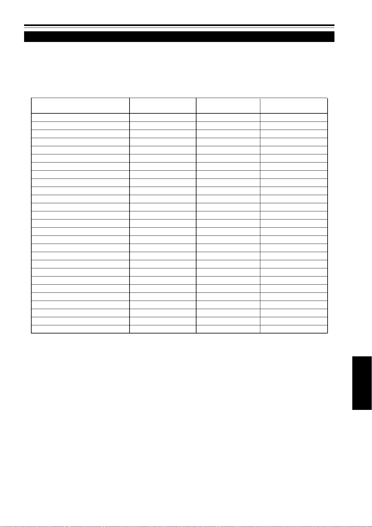
Connexion de divers appareils
Signaux pouvant être entrés dans le projecteur
Les signaux suivants peuvent être entrés dans le projecteur par les cartes VIC (carte d’entrée vidéo) correspondantes.
• Avant la connexion, assurez-vous de mettre hors tension le projecteur et les appareils connectés.
• Lisez attentivement le manuel fourni avec chaque appareil.
■ Signaux analogiques RVB
Les signaux avec les résolutions suivantes peuvent être entrés par la prise d’entrée de la carte analogique VIC RVB.
Résolution de l’écran Fréquence Fréquence Nombre effectif de
(nom standard) horizontale verticale lignes de balayage
DTV (480p 31,5kHz) 31,5Hz 59,9Hz 483
DTV (720p 60Hz) 45,0kHz 60,0Hz 720
DTV (1080p 60Hz) 67,5kHz 60,0Hz 1080
VGA (640 X 480 60Hz) 31,5kHz 59,9Hz 480
VGA (640 X 480 75Hz) 37,5kHz 75,0Hz 480
VGA (640 X 480 85Hz) 43,3kHz 85,0Hz 480
VGA (640 X 480 Macintosh 13") 35,0kHz 66,7Hz 480
SVGA (800 X 600 85Hz) 53,7kHz 85,0Hz 600
SVGA (832 X 624 Macintosh 16") 49,8kHz 74,6Hz 624
XGA (1024 X 768 60Hz) 48,4kHz 60,0Hz 768
XGA (1024 X 768 70Hz) 56,5kHz 70,1Hz 768
XGA (1024 X 768 75Hz) 60,0kHz 75,0Hz 768
XGA (1024 X 768 85Hz) 68,7kHz 85,0Hz 768
XGA (1024 X 768 Macintosh 19") 60,2kHz 74,9Hz 768
XGA (1024 X 768 Macintosh 21") 68,7kHz 75,1Hz 870
SXGA (1280 X 1024 60Hz) 63,9kHz 60,0Hz 1024
SXGA (1280 X 1024 67Hz) 70,8kHz 67,0Hz 1024
SXGA (1280 X 1024 75Hz) 79,9kHz 75,0Hz 1024
SXGA (1280 X 1024 76Hz) 81,2kHz 76,2Hz 1024
SXGA (1280 X 1024 85Hz) 91,1kHz 85,0Hz 1024
UXGA (1600 X 1200 60Hz) 75,0kHz 60,0Hz 1200
UXGA (1600 X 1200 65Hz) 81,2kHz 65,0Hz 1200
UXGA (1600 X 1200 70Hz) 87,5kHz 70,0Hz 1200
UXGA (1600 X 1200 75Hz) 93,8kHz 75,0Hz 1200
UXGA (1600 X 1200 85Hz) 106,3kHz 85,0Hz 1200
QXGA (2048 X 1536 60Hz) 95,3kHz 59,9Hz 1536
QXGA (2048 X 1536 60Hz) 95,7kHz 60,0Hz 1536
• Les signaux RVB dont la fréquence d’horloge d’un point (pixel) est inférieure à 25 MHz ou supérieur à 280 MHz ne sont
pas disponibles.
• Les signaux SVGA dont la fréquence d’horloge d’un point (pixel) est inférieure à 50 MHz ne sont pas disponibles.
• Si vous souhaitez entrer un signal NTSC, doublez le signal avec un doubleur de lignes.
• La résolution et les fréquences de balayage sont comprises dans la plage spécifiée sur le tableau de cette page.
Assurez-vous que la résolution et la fréquence de balayage du signal vidéo sont comprises dans la plage. Un signal
vidéo en dehors de la plage ne peut pas être utilisé. (Certains signaux en dehors de la plage peuvent être projetés.
Cependant ils peuvent ne pas être assez nets. Inversement, certains signaux à l’intérieur de la plage peuvent nécessiter
un ajustement en fonction de la carte vidéo utilisée.)
Quand un signal autre que ceux du tableau de cette page est entré, l’image peut être partiellement effacée ou un
défilement de l’image peut apparaître.
Certains signaux à l’intérieur de la plage de fréquences peuvent ne pas être affichés normalement en fonction du type de
signal.
Les signaux à synchronisation composite (C
fonction de l’appareil connecté.
■ Signaux analogique HD
Les signaux HDTV entrelacés peuvent être entrés par la prise d’entrée de la carte VIC analogique HD. Les signaux NTSC
ne sont pas disponibles.
■ Signaux numériques HD
Les signaux numériques HD peuvent être entrés par la prise d’entrée de la carte VIC HD-SDI au format SDI (et peuvent
être sortis en boucle).
S) et à synchronisation sur G (V) ne peuvent pas être pris en charge en
ÇAIS
FRAN
25
Page 92

Connexion de divers appareils (suite)
Exemples de configuration du système
Avant la connexion, assurez-vous de mettre hors tension le projecteur et les autres appareils à
connecter.
• Lisez aussi les modes d’emploi qui accompagnent chaque appareil.
Exemple d’un système de base
• En connectant un commutateur RVB, diverses sources d’entrée peuvent être entrées dans le projecteur en utilisant
des signaux RVB. En utilisant la télécommande fournie, vous pouvez choisir le canal pour la source d’entrée et
projeter une image optimale de la source.
• En connectant un commutateur spécialisé, vous pouvez commuter le canal du projecteur automatiquement en choisissant le
canal sur le commutateur spécialisé.
Commutateur RVB (non fourni)
HDTV 1
Projecteur
MENU
VIC SELECT
STAND BY
1
HIDE
OPERATE
23KEY STONE
ENTER
EXIT
T
ZOOM
FOCUS
CONTROL
W
REMOTE
RS-232C IN
RS-232C OUT
RGB Analog VIC
B
G
R
S
H/C
V
HDTV 2
Ordinateur 1
Commutateur spécialisé
Ordinateur 2
(non fourni)
Remarques
• L’image vidéo reproduite par des appareils, tels qu’un magnétoscope, dont le signal est instable et peut être déformée. (Cela peut se
produire quand le projecteur n’est pas encore ajusté, au moment de l’installation, ou quand un nouvel appareil est ajouté.)
Dans ce cas, consultez votre revendeur pour ajuster le projecteur.
• Pour l’achat et l’installation du commutateur spécialisé, consultez votre revendeur.
26
Page 93

Connexion de divers appareils (suite)
Connexion d’appareils RVB
Avant la connexion, assurez-vous de mettre hors tension le projecteur et les appareils RVB.
• Lisez attentivement les modes d’emploi qui accompagnent chaque appareil.
• Préparez et utilisez des câbles de connexion RVB disponibles séparément.
• La détection des signaux H/V ou Cs provoque la commutation automatique sur la synchronisation extérieure. L’ordre de
priorité est H/V > Cs.
• Ordinateur de bureau
Au moniteur
connecté
À B
RGB Analog VIC
B
V
À V
Câble de connexion RVB
(non fourni)
À G
G
H/C
S
À H/Cs
À R
R
• Appareils à sortie RVB
Lecteur de disque laser, etc.
À R
À G
À B
À H/Cs
À V
ÇAIS
FRAN
27
Page 94

Connexion de divers appareils (suite)
Connexion d’appareils analogiques HD
Si vous installez une carte VIC (carte d’entrée vidéo) analogique HDTV au projecteur, vous pouvez utiliser des appareils
analogiques HD avec des prises Y, P
Avant la connexion, assurez-vous de mettre hors tension le projecteur et les appareils connectés.
• Lisez attentivement les modes d’emploi qui accompagnent chaque appareil.
• Préparez et utilisez un câble de connexion analogique HD disponible séparément.
• Ordinateur de bureau
b et Pr.
HDTV Analog VIC
Carte VIC analogique HDTV
Y
P
b
P
r
• Appareils analogiques HD
À Y, Pb et Pr
À Y, Pb et Pr
À Y
À Pb
Câble de connexion analogique HD
(non fourni)
À Pr
28
Page 95

Connexion de divers appareils (suite)
Connexion d’appareils numériques HD
Si vous installez une carte VIC (carte d’entrée vidéo) HD-SDI au projecteur, vous pouvez utiliser des appareils numériques
HD munis d’une interface SDI.
Avant la connexion, assurez-vous de mettre hors tension le projecteur et les appareils connectés.
• Lisez attentivement les modes d’emploi qui accompagnent chaque appareil.
• Préparez et utilisez un câble de connexion coaxial SDI disponible séparément.
Carte VIC HD-SDI
HD-SDI VIC
IN
• Ordinateur de bureau
OUT
• Appareils numériques HD
À OUT
To IN
À IN
À OUT
À IN
À OUT
Câble coaxial SDI
(non fourni)
• Moniteur numérique HD
À IN
• La carte VIC HD-SDI a une prise OUT qui vous permet
de connecter un moniteur numérique HD ou un autre
appareil.
29
ÇAIS
FRAN
Page 96

Connexion de divers appareils (suite)
Connexion d’appareils qui commandent le projecteur
Si vous connectez un ordinateur au projecteur, vous pouvez commander ce dernier en utilisant l’ordinateur.
Avant la connexion, assurez-vous de mettre hors tension le projecteur et l’ordinateur.
• Lisez attentivement le mode d’emploi fourni avec chaque appareil à connecter.
• Préparez et utilisez un câble de connexion RS-232C disponible séparément.
CONTROL
REMOTE
RS-232C OUT
Câble de connexion RS-232C
(non fourni)
RS-232C IN
• Quand un autre DLA-QX1G est connecté à ce projecteur à l’aide de la prise RS-232C OUT, vous pouvez utiliser
l’ordinateur pour commander plusieurs DLA-QX1G en même temps.
Pour les détails, consultez votre revendeur.
30
Page 97

Connexion de divers appareils (suite)
Connexion du cordon d’alimentation (fourni)
Une fois que tous les appareils ont été connectés, connectez le cordon d’alimentation du projecteur. Pour l’instant, ne
mettez pas l’interrupteur MAIN POWER sur la position ON.
• Ne mettez pas le projecteur sous tension avant d’installer l’objectif (non fourni). Sinon, cela causerait la déformation du
capuchon du trou de l’objectif (noir), installé initialement, à cause de la chaleur de la lampe source de lumière.
■ Préparation pour le Royaume-Uni uniquement
Fixez au cordon d’alimentation une fiche qui correspond
à la prise murale. Pour les détails, consultez votre
revendeur.
N
I
C
2
3
2
S
R
T
U
O
C
2
3
2
S
R
E
T
O
M
L
E
O
R
T
R
T
N
R
O
U
C
N
E
M
S
S
C
U
/
C
O
H
F
G
M
O
O
Z
T
C
E
L
C
I
E
V
S
V
B
C
I
V
g
o
W
l
a
n
A
R
1
E
B
T
N
G
E
R
2
E
N
E
O
D
T
O
S
M
Y
E
K
T
I
X
E
Y
3
B
E
T
D
A
N
R
A
E
T
P
S
O
1
Cordon d’alimentation (fourni)
À une prise murale
200 V à 240 V , phase simple
2
ATTENTION
Pour éviter les incendies et les électrocutions,
respectez ce qui suit:
• Lorsque vous n’utilisez pas les appareils, débranchez leurs
cordons d’alimentation des prises secteur murales.
• Ne connectez pas les appareils en utilisant des cordons
d’alimentation autres que les cordons fournis.
• N’utilisez pas une tension différente de la tension indiquée.
• Ne coupez pas, n’endommagez pas ni ne modifiez les cordons
d’alimentation. Ne mettez pas d’objets lourds dessus, ne chauffez
pas ni ne tirez sur les cordons d’alimentation, car ils seraient
endommagés.
• Ne branchez ni ne débranchez les fiches avec les mains mouillées.
■Pour utiliser le projecteur
• Retirez le capuchon d’objectif avant
d’utiliser le projecteur.
ATTENTION
• Assurez-vous de retirer le capuchon; sinon, il risque d’être
déformé (ou perdre sa qualité) ou fondu, ou causer un
incendie ou un mauvais fonctionnement.
• Ne faites pas fonctionner le projecteur avec le capuchon
d’objectif attaché. Cela pourrait déformer le capuchon
d’objectif à cause de la chaleur. Un capuchon d’objectif
métallique peut devenir chaud et causer des blessures.
1 Insérez le cordon d’alimentation
fourni dans la prise d’entrée
d’alimentation (AC IN
) du
projecteur.
1. Retirez le couvercle de la prise d’entrée
d’alimentation.
Le couvercle est de type à vis. Tournez-le dans la
direction de la flèche pour le retirer.
2. Insérez la fiche du cor don d’alimentation fourni
dans la prise d’entrée d’alimentation du projecteur .
Alignez la rainure de la fiche du cordon
d’alimentation du projecteur avec la griffe de la prise
d’entrée d’alimentation du projecteur et poussez la
fiche fermement.
Ensuite, tournez la bague sur la fiche dans la
direction de la flèche pour la fixer.
2 Insérez la fiche du cordon
d’alimentation fourni sur une
prise secteur murale.
3 (Pour les États-Unis uniquement)
Tournez la fiche vers la droite
pour la fixer.
ÇAIS
FRAN
Capuchon
d’objectif
ATTENTION
• Comme la puissance requise par le projecteur est élevée,
assurez-vous d’insérer la fiche d’alimentation directement dans
une prise murale.
• Ce projecteur nécessite une prise murale à simple phase, 3 fils et
200V à 240V.
31
Page 98

Fonctionnement de base
■ Touches du projecteur
Indicateur STAND BY
Affichage de code d’état
Indicateur OPERATE
STAND BY
OPERATE
Y
D B
TAN
S
Touche OPERATE
R
E
T
O
M
L
E
O
R
R
T
T
N
O
C
NU
E
M
US
OC
F
OM
O
Z
T
C
I
EC
EL
C S
VI
1
2
E
DE
TON
O
M
Y S
E
K
3
E
RAT
E
OP
V
V
B
g
o
l
W
a
n
A
B
ER
T
G
EN
R
XIT
E
Ce qui suit décrit la procédure de base pour l’utilisation
normale du projecteur.
1. Mise sous tension
1 Mettez l’interrupteur MAIN
2
N
I
C
2
3
2
S
R
T
U
O
C
2
3
2
S
R
S
C
/
H
G
POWER du projecteur sur ON.
ON [ ❙ ]: L’appareil est mis sous tension et l’indicateur
STAND BY s’allume. “00” apparaît sur
l’affichage de code d’état.
Indicateur du projecteur
STAND BY
OPERATE
2 Appuyez sur la touche OPERATE
pendant plus d’une seconde (sur
le panneau de commande ou sur
la télécommande).
• L’indicateur OPERATE s’allume et “01” apparaît sur
l’affichage de code d’état.
■ Télécommande
HIDE
LOCK UNLOCK
ENTER
EXIT MENU
OPERATE
BACK
LIGHT
Interrupteur MAIN POWER
Touche OPERATE
1
2
Télécommande
OPERATE
Projecteur
OPERATE
Indicateur du projecteur
STAND BY
OPERATE
Remarques
• Après avoir mis l’appareil sous tension, l’écran peut apparaître
brouillé pendant quelques secondes, mais ce n’est pas un
mauvais fonctionnement.
• Après que l’indicateur OPERATE s’allume, il peut demander plus
d’une minute à la lampe pour chauffer et fonctionner
correctement.
32
Page 99

Fonctionnement de base (suite)
■ Touches du projecteur
Indicateur STAND BY
Affichage de code d’état
Indicateur OPERATE
STAND BY
OPERATE
Y
B
D
N
A
T
S
Touche OPERATE
2
3
2
S
R
E
T
O
M
L
E
O
R
R
T
T
ON
C
U
N
E
M
S
U
C
O
F
M
O
O
Z
T
C
C
I
LE
V
E
V
B
S
g
IC
V
o
l
W
a
n
A
B
R
E
1
T
G
N
E
R
2
E
N
E
O
D
T
O
S
M
Y
E
K
IT
X
E
3
TE
A
R
E
P
O
■ Mise hors tension
1 Appuyez sur la touche OPERATE
pendant plus d’une seconde (sur
le panneau de commande ou sur
1
IN
C
2
3
2
-
S
R
T
U
O
C
R
S
C
/
H
G
la télécommande).
• L’indicateur OPERATE s’éteint et l’indicateur STAND
BY se met à clignoter.
•“07” apparaît sur l’affichage de code d’état.
Télécommande
OPERATE
Projecteur
OPERATE
Indicateur du projecteur
STAND BY
OPERATE
Interrupteur MAIN POWER
■ Télécommande
OPERATE
HIDE
BACK
LIGHT
LOCK UNLOCK
ENTER
EXIT MENU
Remarque
• Pour changer la langue du menu affiché
L’anglais est réglé quand le projecteur est expédié de l’usine. La
langue d’affichage peut être choisie parmi six langues:
(japonais), ENGLISH (anglais), DEUTSCH (allemand), ESPAÑOL
(espagnol), ITALIANO (italien), et FRANÇAIS.
Touche OPERATE
2
1
Remarque
• Vous ne pouvez pas annuler le processus de mise hors tension
avant que “07” change en “06” ou “00” sur l’affichage de code
d’état.
2 Mettez l’interrupteur MAIN
PO WER sur la position OFF
quand “00” apparaît sur
l’affichage de code d’état.
‡‡
OFF [
‡]: L’appareil se met complètement hors tension
‡‡
et l’indicateur STAND BY s’éteint.
Indicateur du projecteur
STAND BY
OPERATE
* Ne mettez pas l’appareil hors tension avec
l’interrupteur MAIN POWER avant que “00”
n’apparaisse sur l’affichage de code d’état (ou
pendant que l’indicateur STAND BY clignote). Les
ventilateurs de refroidissement continuent de
fonctionner pendant environ 10 minutes.
ÇAIS
FRAN
(Suite à la page suivante)
33
Page 100

Fonctionnement de base (suite)
■ Touches du projecteur
Touches VIC SELECT 1, 2, 3
HIDE
KEY STONE
VIC SELECT
1
2
3
EXIT
2.
Sélection de la carte VIC à utiliser
Appuyez sur une touche VIC SELECT 1, 2
ou 3 pour choisir la carte VIC souhaitée.
(Ou appuyez sur la touche VIC 1, 2 ou 3 de
la télécommande pour choisir la carte VIC
souhaitée)
Télécommande
VIC1 VIC2 VIC3
N
I
C
2
3
2
-
S
R
T
U
O
C
2
3
2
S
R
E
T
O
M
L
E
O
R
R
T
T
N
R
O
C
NU
ME
S
C
/
CUS
O
H
F
G
M
O
O
Z
ECT
C
I
SEL
VIC
1
2
NE
O
DE
T
O
S
M
KEY
Y
3
E
T
A
ND B
A
PER
ST
O
V
V
B
g
W
o
l
a
n
A
ER
B
ENT
G
R
T
I
EX
Affichage de l’écran
VIC 1
Projecteur
VIC SELECT
1
2
3
Affichage de
la ligne
d’entrée
■ Télécommande
UNLOCK
ENTER
EXIT
VIC1 VIC2 VIC3
T
SHIFT FOCUS
ZOOM
W
KEYSTONE
SHUTTER
ON
OFF
MENU
T
DIGITAL
ZOOM
W
Touches VIC 1, 2, 3
* Quand “5sec” est choisi pour l’affichage de la ligne
d’entrée dans les menus, l’affichage de la ligne
d’entrée apparaît en haut à droite de l’écran pendant
environ cinq secondes. Cependant, il n’apparaîtra pas
si l’affichage de la ligne d’entrée est réglé sur “OFF”.
Pour les détails, référez-vous à la page 46.
Remarque
• Quand aucun signal n’entre dans le projecteur par la carte VIC
choisie, le menu sans signal apparaît sur l’écran. Référez-vous à
la page 39.
34
 Loading...