

Page 1
For Customer Use:
Enter the Model No. and Serial No.
which are located on the top or
bottom of the cabinet. Retain this
information for future reference.
Model No.
Serial No.
LVT1756-001A
[U]
Page 2
Thank you for purchasing a JVC product. Please read all instructions carefully before operation, to
ensure your complete understanding and to obtain the best possible performance from the unit.
For safety....
• Do not raise the volume level too much, as this will block outside sounds, making driving
dangerous.
CAUTIONS AND NOTES
This unit is designed to operate on 12 V DC, NEGATIVE ground electrical systems.
• To prevent short circuits, we recommend that you disconnect the battery’s negative terminal and
make all electrical connections before installing the unit.
• Cover the unused terminals with insulating tape to prevent them from short circuiting.
• When an extension lead is used, it should be as thick and short as possible; connect it firmly with
insulating tape.
• Be sure to leave an appropriate space between the antenna and the wires of this unit.
• When replacing the fuse, only use a 30 A fuse.
• Do not let foreign objects get inside the unit.
• To keep the heat dissipation mechanism running effectively, wipe the accumulated dust off
periodically.
• Using this subwoofer system with the volume on loud for a long period of time will exhaust the
battery, while the engine is turned off or while the engine is idling.
DO NOT disassemble the units since there are no user serviceable parts inside.
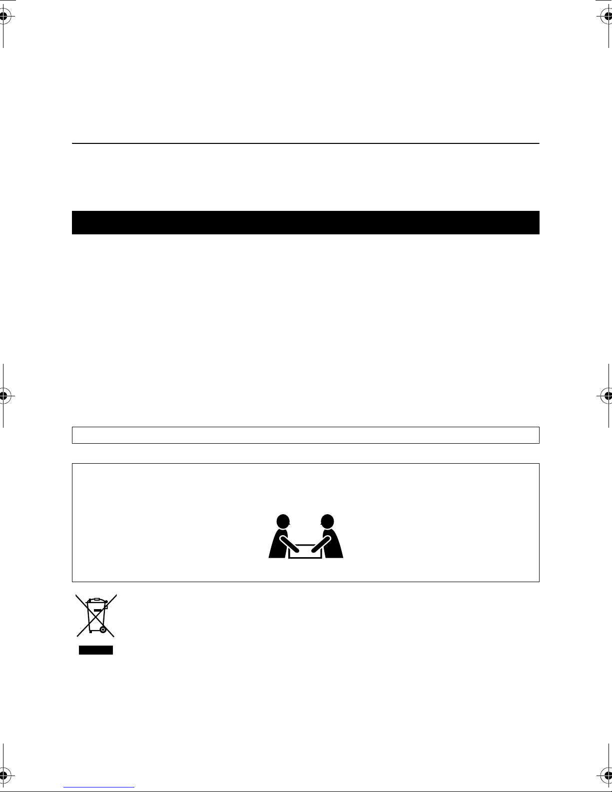
CAUTION
To avoid personal injury or accidentally dropping the unit, have two persons unpack, carry,
and install the unit.
CS-BGS5120 : 24 kg (53 lbs)
[European Union only]
G-1
Page 3
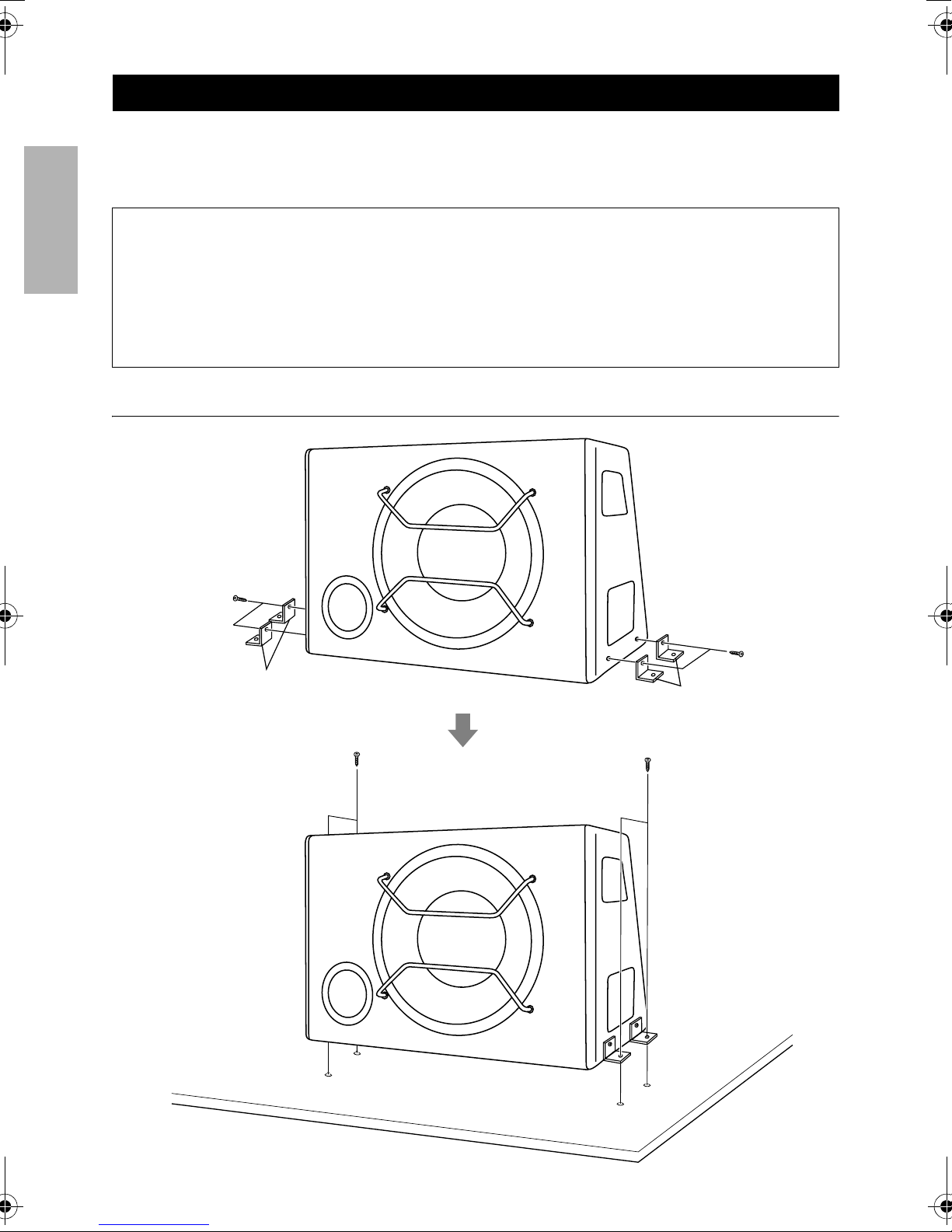
INSTALLATION
Mount this unit on a firm surface, such as on the floor.
• Since heat is generated in this unit, do not mount near flammable objects. In addition, mount in an
area that will not prevent the unit from dissipating heat.
CAUTIONS
ENGLISH
• When mounting this unit, be sure to use the screws provided. If any other screws are used,
there is a risk of loosening the unit or damaging internal parts.
Before drilling holes on the floor to install the unit, make sure that there is a sufficient space
under the floor so that you do not drill holes in the fuel tank, etc.
This unit generates a strong magnetic field. Never place cassette tapes or magnetic cards
nearby the unit; otherwise, data recorded in those media will be erased.
Install this unit with the supplied screws.
Tapping screw (supplied)
ø4 mm c 16 mm
(Dia. 3/16 inch c 21/32 inch)
Tapping screw (supplied)
ø4 mm c 16 mm
(Dia. 3/16 inch c 21/32 inch)
Stay
Tapping screw (supplied)
ø4 mm c 16 mm
(Dia. 3/16 inch c 21/32 inch)
Stay
Tapping screw (supplied)
ø4 mm c 16 mm
(Dia. 3/16 inch c 21/32 inch)
1
Page 4

CONNECTIONS
If your receiver is equipped with Line Output, connect as in A. If your receiver is NOT equipped
with Line Output, connect as in B.
Insulation tape (supplied)
A
After connection ,wrap the
insulation tape around the
terminals.
ENGLISH
Audio cord
(not supplied)
Line output of
receiver
Speaker input connector
(supplied)
B
(not supplied)
Remote output wire of receiver
Gray / Black
White
White / Black
30 A fuse
Screw (not supplied)
Gray
Speaker output of receiver
Right (a)
Right (b)
Left (a)
Left (b)
Connect to battery “+“.
CAUTIONS
To prevent short circuits while making connections, keep the battery’s negative terminal
disconnected.
• When using a power cord (purchased separately), be sure to place the 30 A fuse near the
battery as shown.
• Connect the lead wire (power cord) through which power is supplied directly to the battery’s
+ terminal only after all the other connections have been made.
The proper lead wire connected to each POWER terminal is as follows.
• + B and GND: cross section of more than 8 mm
• REM: cross section of 0.5 mm2 to 1 mm
Connect to the metallic body (chassis and so on)
of the car.
2
2
2
Page 5

When using speaker input terminal [HIGH INPUT]
NOTE:
• If your receiver is equipped with the DSP (Digital Signal Processor), connect this unit to the front
speaker output of the receiver.
When using LINE IN jacks [INPUT]
NOTES:
ENGLISH
• If your receiver is equipped with the DSP (Digital Signal Processor), connect this unit to the Front
Line Output jacks of the receiver.
• When connecting to the Line Output jacks of the receiver, adjust the output level of the receiver
so that the sound will not be distorted.
When connecting to subwoofer output of receiver
Set the subwoofer output level to the maximum on your receiver.
• Use the input LEVEL controller of the unit to adjust the volume. (When sound is distorted, lower
the subwoofer output level on your receiver.)
NOTE:
• Adjust the subwoofer output level of the receiver so that the sound will not be distorted.
When connecting 5.1 channel subwoofer output of receiver
Set the subwoofer output level to the maximum on your decoder.
• Use the input LEVEL controller of the unit to adjust the volume.
NOTE:
• Adjust the output level of the decoder so that the sound will not be distorted.
CAUTIONS
Ground wire connection
Ground wire
Firmly attach the ground wire to the metallic body or to the chassis of the car—to
the place uncoated with paint (if coated with paint, remove the paint before
attaching the wire). Failure to do so may cause noise.
• Be sure to connect the power lead to the battery.
• If the receiver does not have a Remote output wire, be sure to connect the REM terminal of
this unit to the ACC power.
After connection, reconnect the battery negative terminal and make sure stop lamps and others
can operate normally.
3
Page 6

PHASE AND SOUND ADJUSTMENT
Use CD with rich bass sound and adjust phase and sound.
AB
ENGLISH
C
D
A PHASE switch
Select either normal (NOM) or reverse (REV), which reproduce a better sound. This switch is preset
to NOM when the unit is shipped.
B POWER/PROTECTOR lamp
The lamp lights in green while the unit is turned on. When the lamp does not light or lights in red
with the unit on, it indicates there may be any trouble.
C Input LEVEL controller
The input level can be adjusted with this control. Adjust the level while listening to the sound. This
control is preset to the center position when the unit is shipped.
D LPF (Low-Pass Filter) controller
Adjust the cutoff frequency (the Low-Pass Filter transmits frequencies lower than the cutoff
frequency) within the range from 50 Hz to 300 Hz. Adjust the level while listening to the sound.
This control is preset to the center position (80 Hz) when the unit is shipped.
4
Page 7

TROUBLE SHOOTING
For more details, consult JVC IN-CAR ENTERTAINMENT car audio dealer.
No sound is heard.
• Is the REM wire connected correctly?
• Is audio cord connected to the LINE IN jacks?
• Is the speaker input connector connected correctly?
ENGLISH
• Is this subwoofer system grounded?
Alternator noise is heard.
• Keep the power cord away from the audio cord.
• Keep the audio cord away from other electrical cables in the car.
• Confirm if the ground wire is connected securely to a metal part of the car.
• Confirm if the noise originates in the receiver.
DEMENSIONS
250.5 mm (9-29/32 inch)
220 mm (8-11/16 inch)
574 mm (22-5/8 inch)
5
392 mm (15-7/16 inch)
380 mm (14-31/32 inch)
410.5 mm (16-3/16 inch)
Page 8

SPECIFICATIONS
Ty p e Active Subwoofer System (Built-in amplifier)
Speaker Unit 30 cm (11-13/16 inch) cone
Input Terminal LINE IN (1 system), 0.18 V – 4 V
SPEAKER (1 system), 3.9 V – 12 V
Maximum Amplifier Power Output 350 W
Cut-off Frequency 50 Hz – 300 Hz (b12 dB/oct. low pass filter)
Sound Pressure Level 110 dB/ m (with line input: 0.03 V)
Level Control b50 dB to a 6 dB
Center: 0 dB
Power Requirement DC 14.4 V (11 V to 16 V allowance)
Negative ground
Mass 18.8 kg (42 lbs) (Excluding accessories)
Design and specifications are subject to change without notice.
SUPPLIED ACCESSORIES
Speaker input connector 4P 200 mm (7-7/8 inch) c 1 (Including cord)
Stay c 4
Tapping screw ø4 mm c 16 mm (Dia. 3/16 inch c 21/32 inch) c 8
Insulation tape c 1
ENGLISH
6
Page 9

EN, CT, TH
2007 Victor Company of Japan, Limited
0507SKMSANTKC
 Loading...