

Page 1
SERVICE MANUAL
COMPACT COMPONENT SYSTEM
MB664<Rev.002>20088SERVICE MANUAL
MX-KC68J, MX-KC68C, MX-KC68B, MX-KC68E,
MX-KC68EN, MX-KC68EV, MX-KC68A,
MX-KC68UJ, MX-KC68UW, MX-KC38J, MX-KC38C
SP-MXKC68W
SP-MXKC68F
SP-MXKC38
SP-MXKC68F
SP-MXKC38
CA-MXKC68
CA-MXKC38
(MX-KC68B,E,EN,EV)
COPYRIGHT © 2008 Victor Company of Japan, Limited
Lead free solder used in the board (material : Sn-Ag-Cu, melting point : 219 Centigrade)
Lead free solder used in the board (material : Sn-Cu, melting point : 230 Centigrade)
TABLE OF CONTENTS
1 PRECAUTION. . . . . . . . . . . . . . . . . . . . . . . . . . . . . . . . . . . . . . . . . . . . . . . . . . . . . . . . . . . . . . . . . . . . . . . . . 1-5
2 SPECIFIC SERVICE INSTRUCTIONS . . . . . . . . . . . . . . . . . . . . . . . . . . . . . . . . . . . . . . . . . . . . . . . . . . . . . . 1-8
3 DISASSEMBLY . . . . . . . . . . . . . . . . . . . . . . . . . . . . . . . . . . . . . . . . . . . . . . . . . . . . . . . . . . . . . . . . . . . . . . . 1-8
4 ADJUSTMENT . . . . . . . . . . . . . . . . . . . . . . . . . . . . . . . . . . . . . . . . . . . . . . . . . . . . . . . . . . . . . . . . . . . . . . . 1-20
5 TROUBLESHOOTING . . . . . . . . . . . . . . . . . . . . . . . . . . . . . . . . . . . . . . . . . . . . . . . . . . . . . . . . . . . . . . . . . 1-21
COPYRIGHT © 2008 Victor Company of Japan, Limited
No.MB664<Rev.002>
2008/8
Page 2
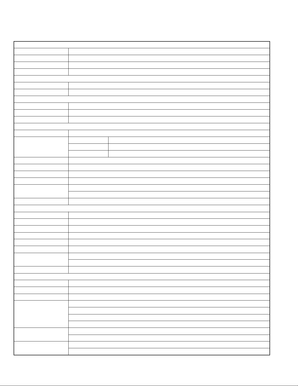
SPECIFICATION
MX-KC68J/C/MX-KC38J/C
Amplifier section OUTPUT POWER
Main speakers 110 W per channel min. RMS driven into 3Ω at 1 kHz with no more than 10% total harmonic distortion
Speakers/Impedance 3Ω - 6 Ω
Subwoofer (for MX-KC68) 180 W per channel min. RMS driven into 8 Ω at 63 Hz with no more than 10% total harmonic distortion
Speakers/Impedance 8 Ω - 16 Ω
Tuner section
FM tuning range 87.5 MHz - 108.0 MHz
AM tuning range 530 kHz - 1 710 kHz
CD player section
Dynamic range 90 dB
Signal-to-noise ratio 85 dB
Wow and flutter Immeasurable
Main speakers (MX-KC68/SP-MXKC38)
Type 3-Way 3-Speaker Bass-Reflex Type
Speaker units Main Woofer 16 cm (6-5/16 inches) cone x 1
Mid Range 5 cm (2 inches) cone x 1
Tweeter 2 cm (13/16 inches) dome x 1
Power Handling Capacity 110 W
Impedance 3 Ω
Frequency Range 41 Hz - 35 kHz
Sound Pressure Level 83 dB/W•m
Dimensions (approx.) 210 mm x 315 mm x 220 mm (W/H/D)
(8-5/16 inches x 12-7/16 inches x 8-11/16 inches)
Mass (approx.) 3.0 kg (6.7 lbs) each
Subwoofer (MX-KC68)
Type 1-Way Bass-Reflex Type
Speaker 16 cm (6-5/16 inches) cone x 1
Power Handling Capacity 180 W
Impedance 8 Ω
Frequency Range 38 Hz - 5 kHz
Sound Pressure Level 83 dB/W•m
Dimensions (approx.) 210 mm x 315 mm x 242 mm (W/H/D)
(8-5/16 inches x 12-7/16 inches x 9-9/16 inches)
Mass (approx.) 3.4 kg (7.5 lbs)
General
Power requirements AC 120 V , 60 Hz
Audio input AUDIO IN 400 mV/47 kΩ
Power supply to iPod DC 5 V 500 mA
Power consumption 95 W (MX-KC68) - power on
60 W (MX-KC38) - power on
9 W - standby mode, without charging iPod
0.9 W or less - save mode
Dimensions (W x H x D) 215 mm x 307 mm x 309 mm
(8-1/2 inches x 12-1/8 inches x 12-3/16 inches)
Mass (approx.) 3.8 kg (8.4 lbs) (MX-KC68)
3.6 kg (8.0 lbs) (MX-KC38)
Specifications and appearance are subject to change without prior notice.
1-2 (No.MB664<Rev.002>)
Page 3
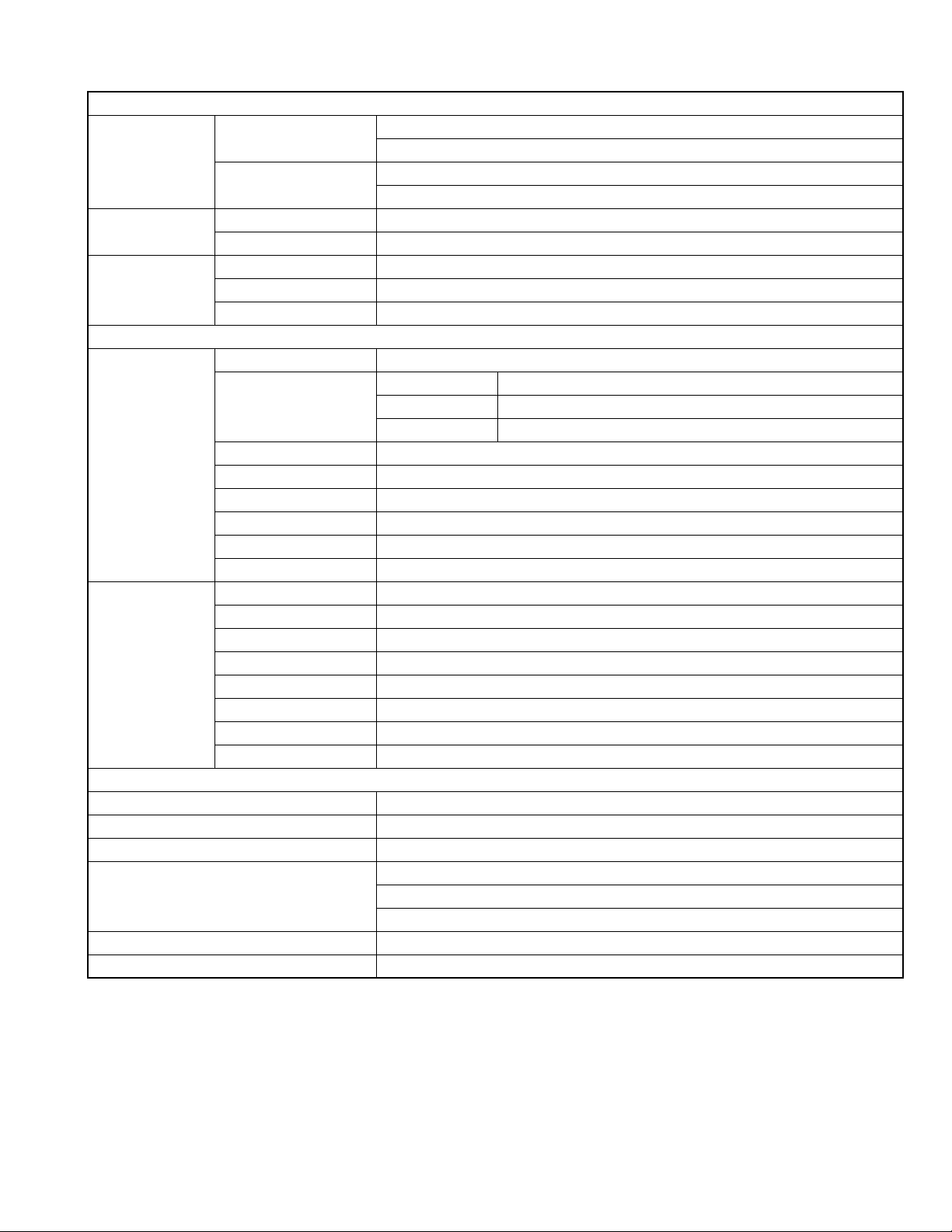
MX-KC68B/E/EN/EV
Amplifier section
OUTPUT POWER Main speakers
Subwoofer
Tuner section FM tuning range 87.50 MHz - 108.00 MHz
AM tuning range 522 kHz - 1 629 kHz
CD player section Dynamic range 86 dB
Signal-to-noise ratio 85 dB
Wow and flutter Immeasurable
Main speakers
(SP-MXKC68F)
Subwoofer
(SP-MXKC68W)
Power requirements AC 230 V , 50 Hz
Audio input AUDIO IN 400 mV/47 kΩ
Power supply to iPod DC 5 V 500 mA
Power consumption 95 W - power on
Dimensions (W x H x D) 215 mm x 307 mm x 309 mm
Mass (approx.) 3.8 kg
Specifications and appearance are subject to change without prior notice.
Type 3-Way 3-Speaker Bass-Reflex Type
Speaker units Main Woofer 16 cm cone x 1
Power Handling Capacity 110 W
Impedance 3 Ω
Frequency Range 41 Hz - 35 kHz
Sound Pressure Level 83 dB/W
Dimensions (approx.) 210 mm x 315 mm x 220 mm (W/H/D)
Mass (approx.) 3.0 kg each
Type 1-Way Bass-Reflex Type
Speaker 16 cm cone x 1
Power Handling Capacity 180 W
Impedance 8 Ω
Frequency Range 38 Hz - 5 kHz
Sound Pressure Level 83 dB/W
Dimensions (approx.) 210 mm x 315 mm x 242 mm (W/H/D)
Mass (approx.) 3.4 kg
110 W per channel min. RMS driven into 3 Ω at 1 kHz with no more than 10% total harmonic distortion
Speakers/Impedance: 3 Ω - 6 Ω
180 W min. RMS driven into 8 Ω at 63 Hz with no more than 10% total harmonic distortion
Speakers/Impedance: 8 Ω - 16 Ω
Speakers
Mid Range 5 cm cone x 1
Tweeter 2 cm dome x 1
•m
•m
General
9 W - standby mode, without charging iPod
0.8 W or less - save mode
(No.MB664<Rev.002>)1-3
Page 4
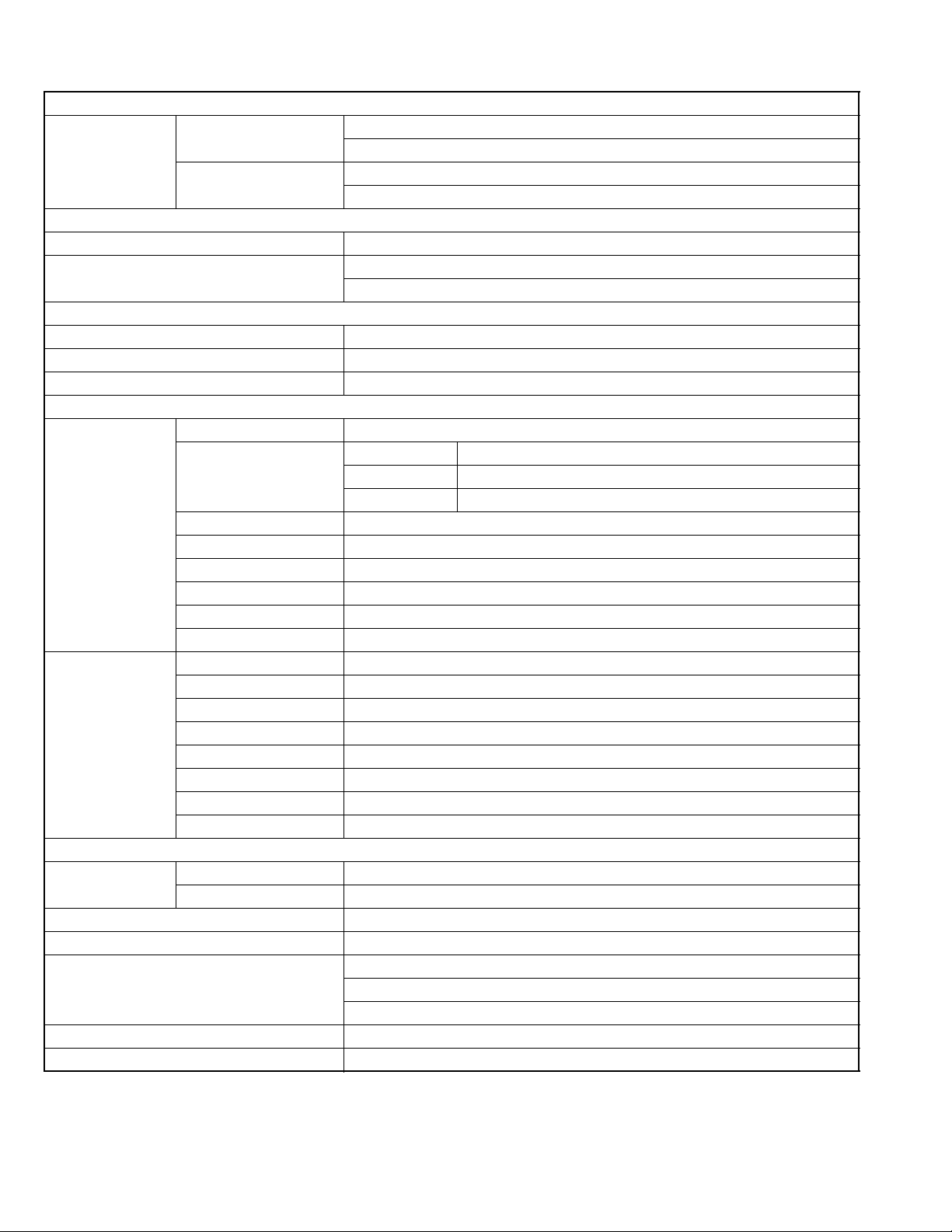
MX-KC68A/UJ/UW
Amplifier section
OUTPUT POWER Main speakers
Subwoofer
FM tuning range 87.50 MHz - 108.00 MHz
AM tuning range 531 kHz - 1 710 kHz (at 9 kHz intervals)
Dynamic range 86 dB
Signal-to-noise ratio 85 dB
Wow and flutter Immeasurable
Main speakers (SPMXKC68F)
Subwoofer
(SP-MXKC68W)
Power requirements For Australia AC 240 V , 50 Hz
Audio input AUDIO IN 400 mV/47 kΩ
Power supply to iPod DC 5 V 500 mA
Power consumption 95 W - power on
Dimensions (W x H x D) 215 mm x 307 mm x 309 mm
Mass (approx.) 3.8 kg
Specifications and appearance are subject to change without prior notice.
Type 3-Way 3-Speaker Bass-Reflex Type
Speaker units Main Woofer 16 cm cone x 1
Power Handling Capacity 110 W
Impedance 3 Ω
Frequency Range 41 Hz - 35 kHz
Sound Pressure Level 83 dB/W
Dimensions (approx.) 210 mm x 315 mm x 220 mm (W/H/D)
Mass (approx.) 3.0 kg each
Type 1-Way Bass-Reflex Type
Speaker 16 cm cone x 1
Power Handling Capacity 180 W
Impedance 8 Ω
Frequency Range 38 Hz - 5 kHz
Sound Pressure Level 83 dB/W
Dimensions (approx.) 210 mm x 315 mm x 242 mm (W/H/D)
Mass (approx.) 3.4 kg
For other countries AC 110 V-127 V/AC 220 V-240 V adjustable with the voltage selector 50 Hz/60 Hz
110 W per channel min. RMS driven into 3 Ω at 1 kHz with no more than 10% total harmonic distortion
Speakers/Impedance: 3 Ω - 6 Ω
180 W per channel min. RMS driven into 8 Ω at 63 Hz with no more than 10% total harmonic distortion
Speakers/Impedance: 8 Ω - 16 Ω
Tuner section
530 kHz - 1 710 kHz (at 10 kHz intervals)
CD player section
Speakers
Mid Range 5 cm cone x 1
Tweeter 2 cm dome x 1
•m
•m
General
9 W - standby mode, without charging iPod
0.8 W or less - save mode
1-4 (No.MB664<Rev.002>)
Page 5
SECTION 1
PRECAUTION
1.1 Safety Precautions
(1) This design of this product contains special hardware and
many circuits and components specially for safety purposes. For continued protection, no changes should be made
to the original design unless authorized in writing by the
manufacturer. Replacement parts must be identical to
those used in the original circuits. Services should be performed by qualified personnel only.
(2) Alterations of the design or circuitry of the product should
not be made. Any design alterations of the product should
not be made. Any design alterations or additions will void
the manufacturers warranty and will further relieve the
manufacture of responsibility for personal injury or property
damage resulting therefrom.
(3) Many electrical and mechanical parts in the products have
special safety-related characteristics. These characteristics are often not evident from visual inspection nor can the
protection afforded by them necessarily be obtained by using replacement components rated for higher voltage, wattage, etc. Replacement parts which have these special
safety characteristics are identified in the Parts List of Service Manual. Electrical components having such features
are identified by shading on the schematics and by ( ) on
the Parts List in the Service Manual. The use of a substitute
replacement which does not have the same safety characteristics as the recommended replacement parts shown in
the Parts List of Service Manual may create shock, fire, or
other hazards.
(4) The leads in the products are routed and dressed with ties,
clamps, tubings, barriers and the like to be separated from
live parts, high temperature parts, moving parts and/or
sharp edges for the prevention of electric shock and fire
hazard. When service is required, the original lead routing
and dress should be observed, and it should be confirmed
that they have been returned to normal, after reassembling.
(5) Leakage shock hazard testing
After reassembling the product, always perform an isolation check on the exposed metal parts of the product (antenna terminals, knobs, metal cabinet, screw heads,
headphone jack, control shafts, etc.) to be sure the product
is safe to operate without danger of electrical shock.Do not
use a line isolation transformer during this check.
• Plug the AC line cord directly into the AC outlet. Using a
"Leakage Current Tester", measure the leakage current
from each exposed metal parts of the cabinet, particularly any exposed metal part having a return path to the
chassis, to a known good earth ground. Any leakage current must not exceed 0.5mA AC (r.m.s.).
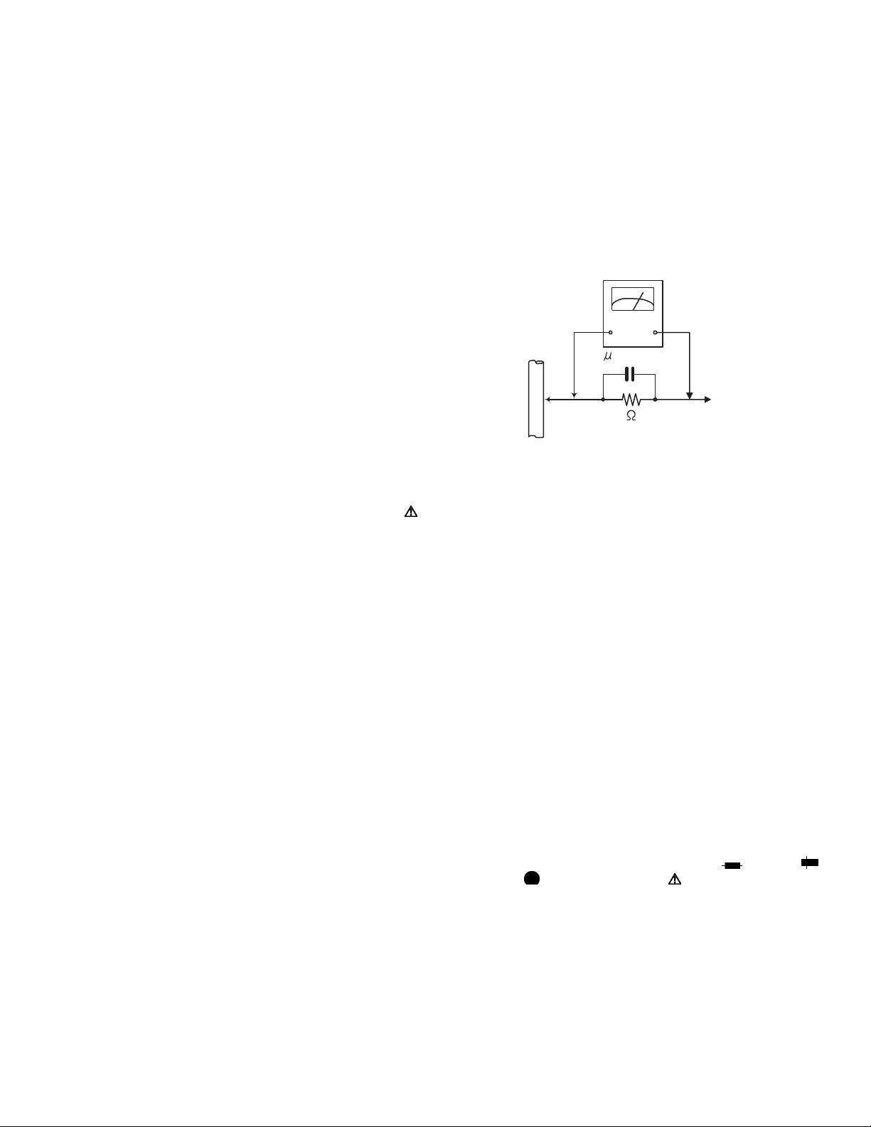
• Alternate check method
Plug the AC line cord directly into the AC outlet. Use an
AC voltmeter having, 1,000Ω per volt or more sensitivity
in the following manner. Connect a 1,500Ω 10W resistor
paralleled by a 0.15µF AC-type capacitor between an ex-
posed metal part and a known good earth ground.
Measure the AC voltage across the resistor with the AC
voltmeter.
Move the resistor connection to each exposed metal
part, particularly any exposed metal part having a return
path to the chassis, and measure the AC voltage across
the resistor. Now, reverse the plug in the AC outlet and
repeat each measurement. Voltage measured any must
not exceed 0.75 V AC (r.m.s.). This corresponds to 0.5
mA AC (r.m.s.).
AC VOLTMETER
(Having 1000
ohms/volts,
or more sensitivity)
0.15 F AC TYPE
Place this
probe on
1500 10W
Good earth ground
1.2 Warning
(1) This equipment has been designed and manufactured to
meet international safety standards.
(2) It is the legal responsibility of the repairer to ensure that
these safety standards are maintained.
(3) Repairs must be made in accordance with the relevant
safety standards.
(4) It is essential that safety critical components are replaced
by approved parts.
(5) If mains voltage selector is provided, check setting for local
voltage.
1.3 Caution
Burrs formed during molding may be left over on some parts
of the chassis.
Therefore, pay attention to such burrs in the case of preforming repair of this system.
1.4 Critical parts for safety
In regard with component parts appearing on the silk-screen
printed side (parts side) of the PWB diagrams, the parts that are
printed over with black such as the resistor ( ), diode ( )
and ICP ( ) or identified by the " " mark nearby are critical
for safety. When replacing them, be sure to use the parts of the
same type and rating as specified by the manufacturer.
(This regulation dose not Except the J and C version)
each exposed
metal part.
(No.MB664<Rev.002>)1-5
Page 6
1.5 Preventing static electricity
Electrostatic discharge (ESD), which occurs when static electricity stored in the body, fabric, etc. is discharged, can destroy the laser
diode in the traverse unit (optical pickup). Take care to prevent this when performing repairs.
1.5.1 Grounding to prevent damage by static electricity
Static electricity in the work area can destroy the optical pickup (laser diode) in devices such as laser products.
Be careful to use proper grounding in the area where repairs are being performed.
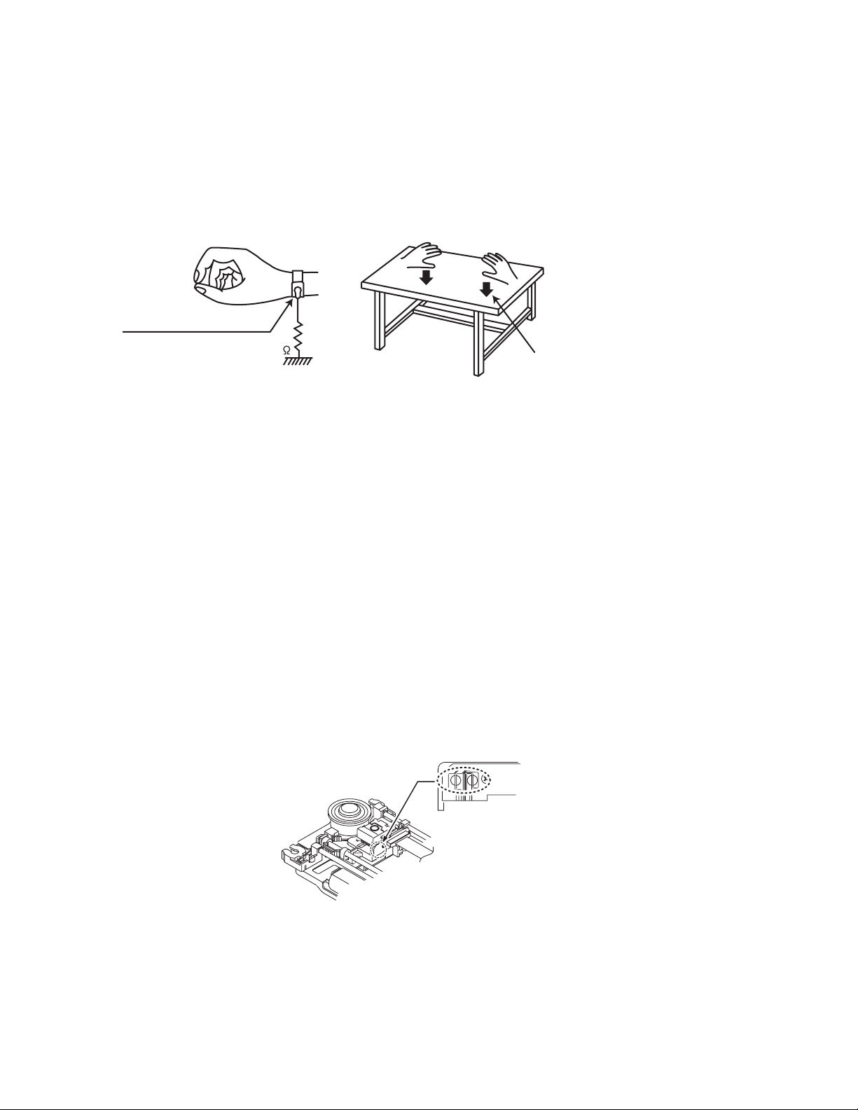
(1) Ground the workbench
Ground the workbench by laying conductive material (such as a conductive sheet) or an iron plate over it before placing the
traverse unit (optical pickup) on it.
(2) Ground yourself
Use an anti-static wrist strap to release any static electricity built up in your body.
(caption)
Anti-static wrist strap
1M
Conductive material
(conductive sheet) or iron palate
(3) Handling the optical pickup
• In order to maintain quality during transport and before installation, both sides of the laser diode on the replacement optical
pickup are shorted. After replacement, return the shorted parts to their original condition.
(Refer to the text.)
• Do not use a tester to check the condition of the laser diode in the optical pickup. The tester's internal power source can easily
destroy the laser diode.
1.6 Handling the traverse unit (optical pickup)
(1) Do not subject the traverse unit (optical pickup) to strong shocks, as it is a sensitive, complex unit.
(2) Cut off the shorted part of the flexible cable using nippers, etc. after replacing the optical pickup. For specific details, refer to the
replacement procedure in the text. Remove the anti-static pin when replacing the traverse unit. Be careful not to take too long a
time when attaching it to the connector.
(3) Handle the flexible cable carefully as it may break when subjected to strong force.
(4) I t is not possible to adjust the semi-fixed resistor that adjusts the laser power. Do not turn it.
1.7 Attention when traverse unit is decomposed
*Please refer to "Disassembly method" in the text for the pickup unit.
• Apply solder to the short land sections before the card wire is disconnected from the connecto on the servo board. (If the card wire
is disconnected without applying solder, the pickup may be destroyed by static electricity.)
• In the assembly, be sure to remove solder from the short land sections after connecting the card wire.
Solder short land section
1-6 (No.MB664<Rev.002>)
Page 7
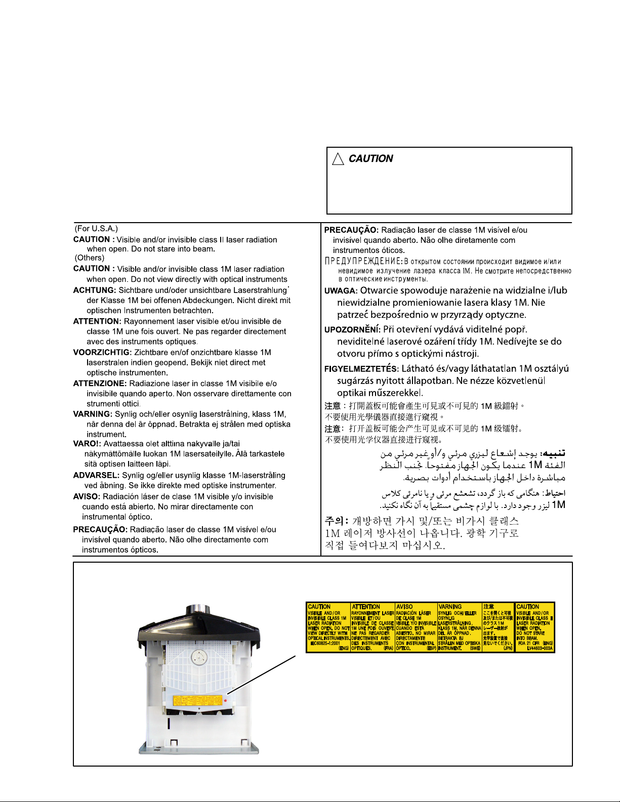
1.8 Important for laser products
1.CLASS 1 LASER PRODUCT
2.CAUTION :
(For U.S.A.) Visible and/or invisible class II laser radiation
when open. Do not stare into beam.
(Others) Visible and/or invisible class 1M laser radiation
when open. Do not view directly with optical instruments.
3.CAUTION : Visible and/or invisible laser radiation when
open and inter lock failed or defeated. Avoid direct
exposure to beam.
4.CAUTION : This laser product uses visible and/or invisible
laser radiation and is equipped with safety switches which
prevent emission of radiation when the drawer is open and
the safety interlocks have failed or are defeated. It is
dangerous to defeat the safety switches.
5.CAUTION : If safety switches malfunction, the laser is able
to function.
6.CAUTION : Use of controls, adjustments or performance of
procedures other than those specified here in may result in
hazardous radiation exposure.
!
Please use enough caution not to
see the beam directly or touch it
in case of an adjustment or operation
check.
REPRODUCTION AND POSITION OF LABELS and PRINT
WARNING LABEL and PRINT
(No.MB664<Rev.002>)1-7
Page 8
SECTION 2
A
SPECIFIC SERVICE INSTRUCTIONS
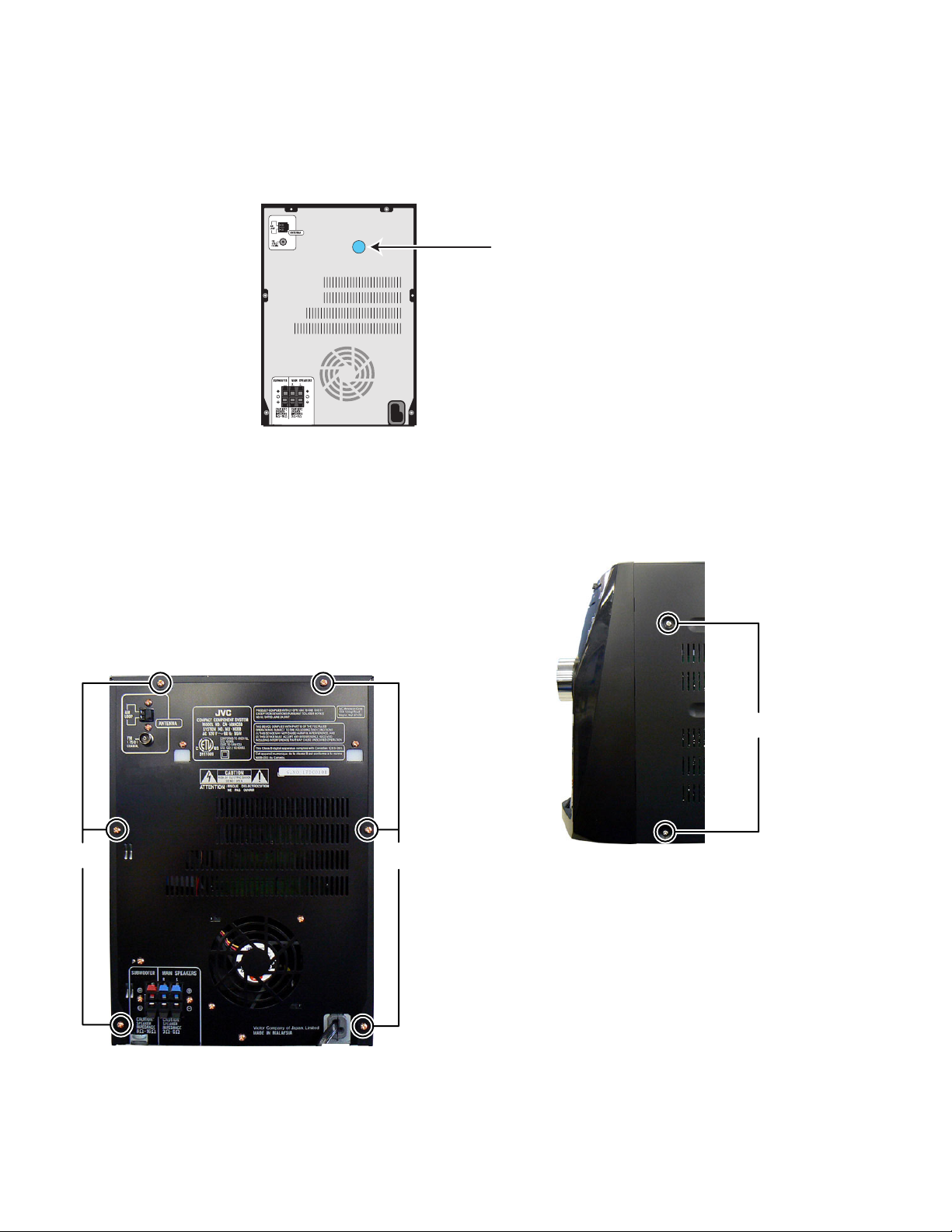
New CD mechanism was added.
In a model using new CD mechanism for, it stick a blue label for identification on the back side.
When it repair the CD mechanism of an article sticking this label on, please use a parts list of FMU-VK1-2M.
A label for identification
SECTION 3
DISASSEMBLY
3.1 Main body (Used figure are MX-KC68J)
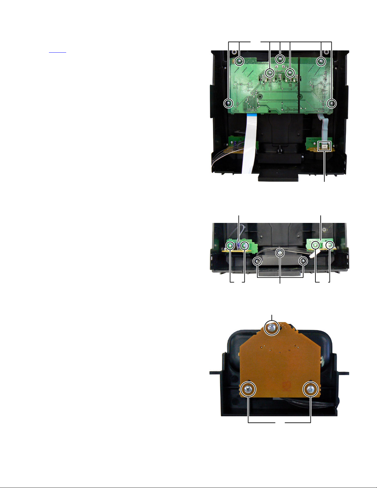
3.1.1 Removing the Metal cover (See Fig.1, 2)
(1) Remove the six screws A attaching the Metal cover. (See
Fig.1)
(2) Remove the four screws B attaching the both side of the
Metal cover. (See Fig.2)
A
B
Fig.2
1-8 (No.MB664<Rev.002>)
Fig.1
Page 9
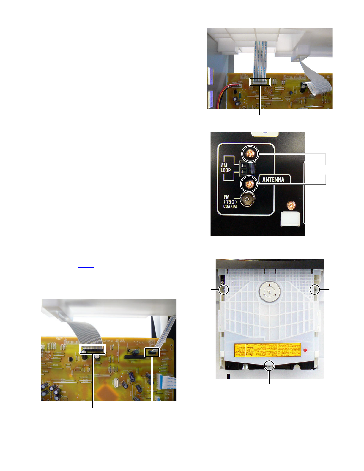
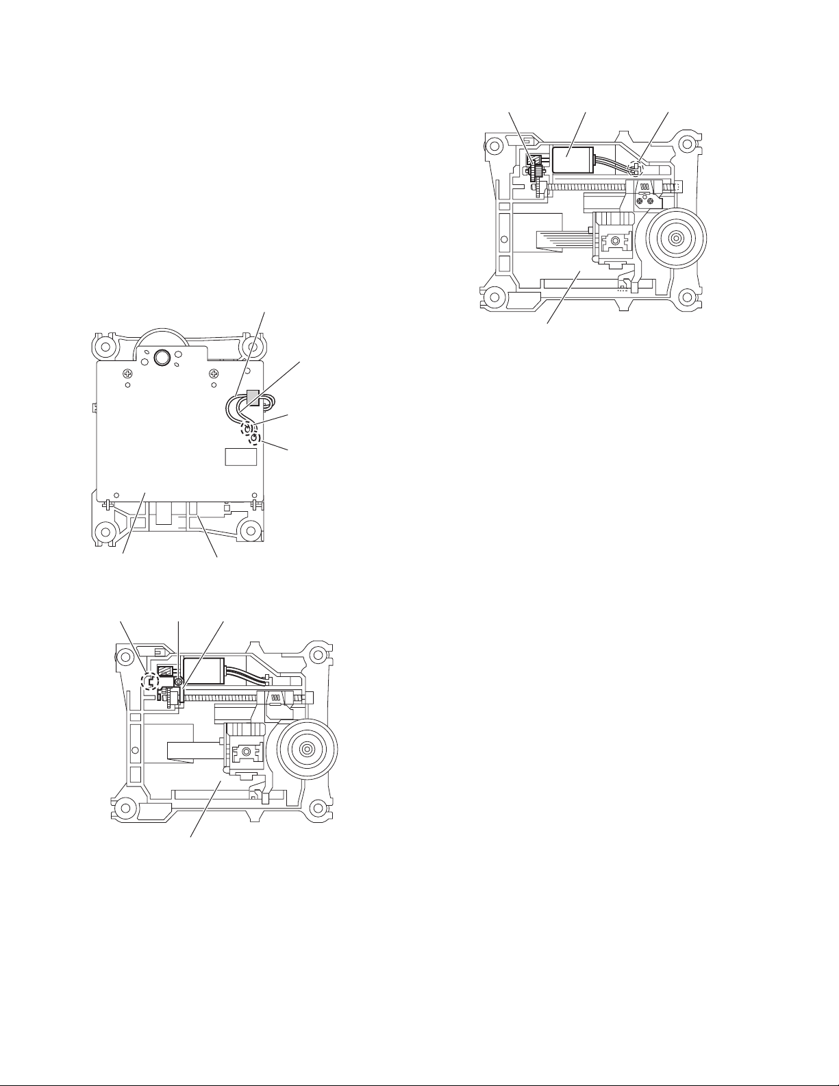
3.1.2 Removing the Tuner pack (See Fig.3, 4)
(1) Disconnect the card wire from Tuner pack connected to
connector CN707
(2) Remove the two screws C attaching the Tuner pack. (See
Fig.4)
of the Micom board. (See Fig.3)
CN707
Fig.3
C
3.1.3 Removing the CD mechanism (See Fig.5, 6)
(1) Disconnect the card wire from CD mechanism connected
to connector CN708
(2) Disconnect the card wire from Loader board connected to
connector CN709 of the Micom board. (See fig.5)
(3) Remove the three screws D attaching the CD mechanism.
(See Fig.6)
of the Micom board. (See Fig.5)
Fig.4
DD
D
Fig.6
CN708 CN709
Fig.5
(No.MB664<Rev.002>)1-9
Page 10
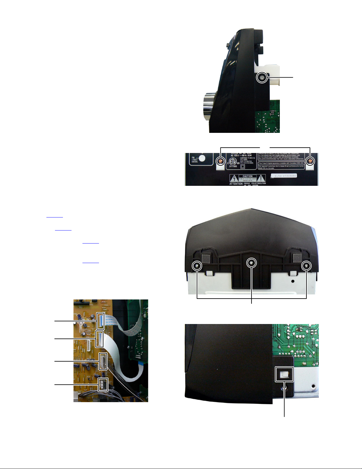
3.1.4 Removing the CD chassis (See Fig.7, 8)
(1) Remove the two screws E attaching the both side of the
Front panel. (See Fig.7)
(2) Remove the two screws F attaching the CD chassis. (See
Fig.8)
E
Fig.7
F
Fig.8
3.1.5 Removing the Front panel (See Fig.9 to 11)
(1) Disconnect he card wire from FL board connected to con-
nector CN700
(2) Disconnect the card wire from Volume board connected to
connector CN701 of the Micom board. (See Fig.9)
(3) Disconnect the connector wire from iPod jack board con-
nected to connector CN702
Fig.9)
(4) Disconnect the flat cable wire from Audio input board con-
nected to connector CN705
Fig.9)
(5) Remove the three screws G attaching the Front panel.
(See Fig.10)
(6) Disengage two hooks a engaged both side of the Front
panel. (See Fig.11)
CN700
CN701
CN702
of the Micom board. (See Fig.9)
of the Micom board. (See
of the Micom board. (See
G
Fig.10
CN705
1-10 (No.MB664<Rev.002>)
Fig.9
Fig.11
hook
a
Page 11
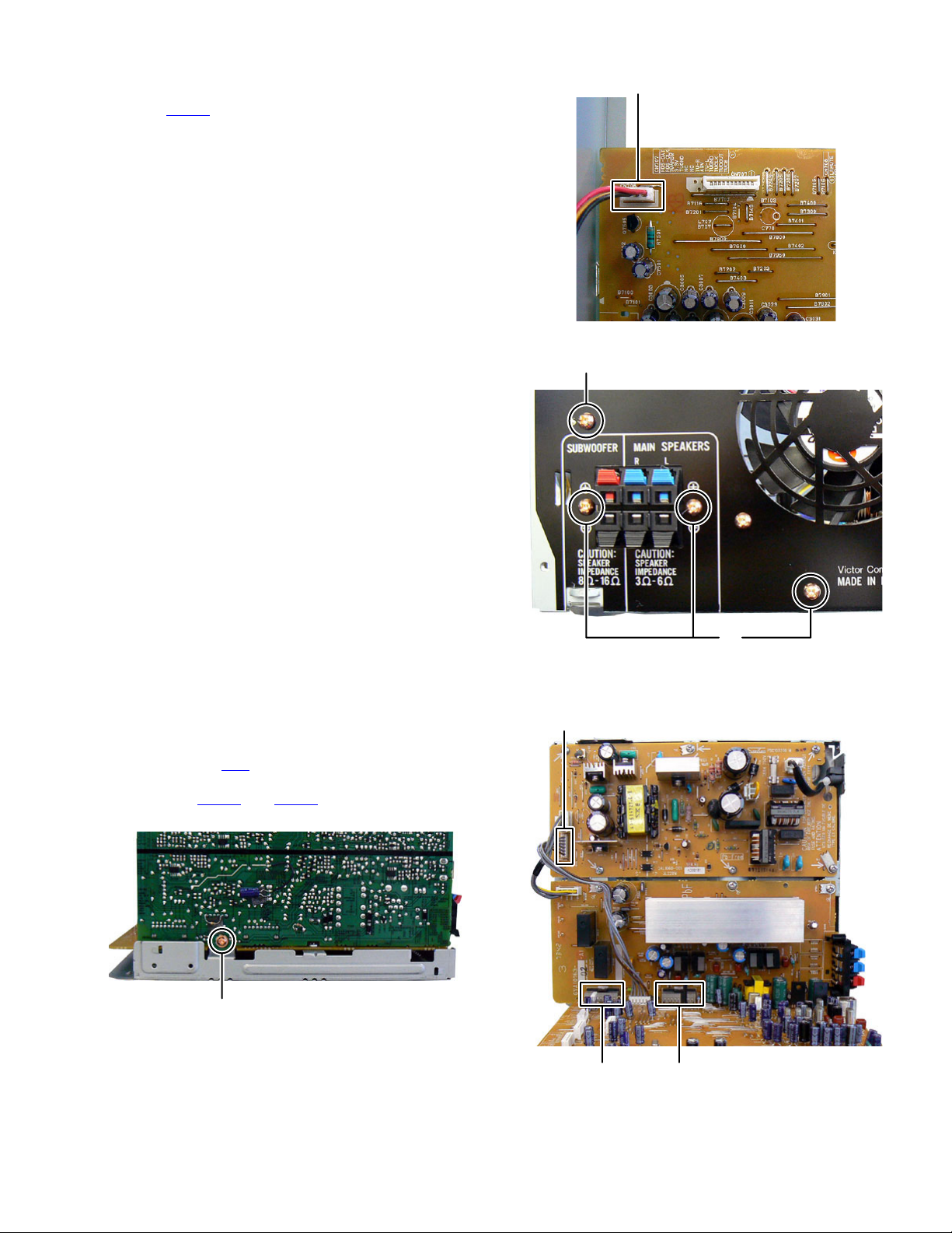
3.1.6 Removing the Rear panel (See Fig.12, 13)
(1) Disconnect the connector wire from Fan connected to con-
nector CN706
(2) Remove the four screws H attaching the Rear panel. (See
Fig.13)
of the Micom board. (See Fig.12)
CN706
Fig.12
H
3.1.7 Removing the Micom board (See Fig.14, 15)
(1) Remove the one screw J attaching the Micom board. (See
Fig.14)
(2) Disconnect the connector wire from Micom board connect-
ed to connector CN3
(3) Disconnect the board to board connectors connected to
connectors CN501 and CN502 of the Power amp board.
(See Fig.15)
of the Power supply unit. (See Fig.15)
J
Fig.14
H
Fig.13
CN3
CN501 CN502
Fig.15
(No.MB664<Rev.002>)1-11
Page 12
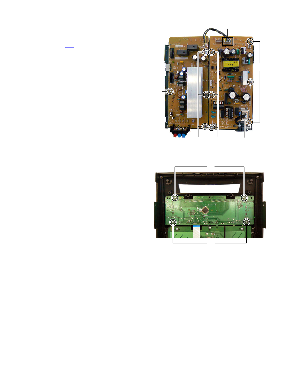
3.1.8 Removing the Power supply unit (See Fig.16)
(1) Disconnect the Power cord connected to connector CN1 of
the Power supply unit.
(2) Disconnect the connector wire from Power amp board con-
nected to connector CN2
(3) Remove the six screws K attaching the Power supply unit.
3.1.9 Removing the Power amp board (See Fig.16)
(1) Remove the four screws L attaching the Power amp board.
of the Power supply unit.
CN2
K
L
3.1.10 Removing the FL board (See Fig.17)
(1) Remove the four screws M attaching the FL board.
Fig.16
M
M
Fig.17
KL
CN1
1-12 (No.MB664<Rev.002>)
Page 13
3.1.11 Removing the Volume board (See Fig.18)
(1) Remove the volume knob.
(2) Disconnect the flat cable wire connected to connector
of the Headphone jack board.
CN951
(3) Remove the seven screws N attaching the Volume board.
3.1.12 Removing the Audio input board (See Fig.19)
(1) Remove the two screws P attaching the Audio input board.
3.1.13 Removing the Headphone jack board (See Fig.19)
(1) Remove the two screws Q attaching the Headphone jack
board.
N
CN951
Fig.18
Audio input board Headphone jack board
3.1.14 Removing the iPod jack board (See Fig.19, 20)
(1) Remove the three screws R attaching the iPod holder.
(See Fig.20)
(2) Remove the three screws S attaching the iPod jack board.
(See Fig.20)
PQ
R
Fig.19
S
S
Fig.20
(No.MB664<Rev.002>)1-13
Page 14
3.2 CD mechanism assembly
• Remove the CD mechanism assembly from main body.
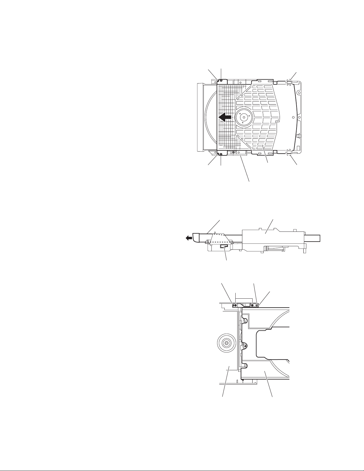
3.2.1 Removing the CD cover
(See Fig.1)
(1) Remove the two screws A attaching the CD cover from bot-
tom side of CD mechanism assembly.
(2) Lift up the CD cover from disengage boss a of the CD
mechanism assembly.
(3) Slide the CD cover to direction of the arrow and remove the
CD cover from fixing part of b.
(4) Remove the CD cover.
Boss a
A
Fixing part b
3.2.2 Removing the tray assembly
(See Fig.2 and 3)
• Remove the CD cover.
(1) Press slide cam and pull out the tray assembly to direction
of the arrow from right side of CD mechanism assembly.
(See Fig.2)
(2) Remove the two screws B attaching the tray assembly
from upper side of CD mechanism. (See Fig.3)
(3) Remove the bussing of the tray assembly from boss c of
the CD mechanism assembly and remove the tray assembly. (See Fig.3)
Boss a
A
CD mechanism assembly
Tray assembly CD mechanism assembly
Slide cam
Boss c
B
CD cover
Fig.1
Fig.2
Boss c
Bussing
Fixing part b
1-14 (No.MB664<Rev.002>)
Tray assemblyCD mechanism assembly
Fig.3
Page 15
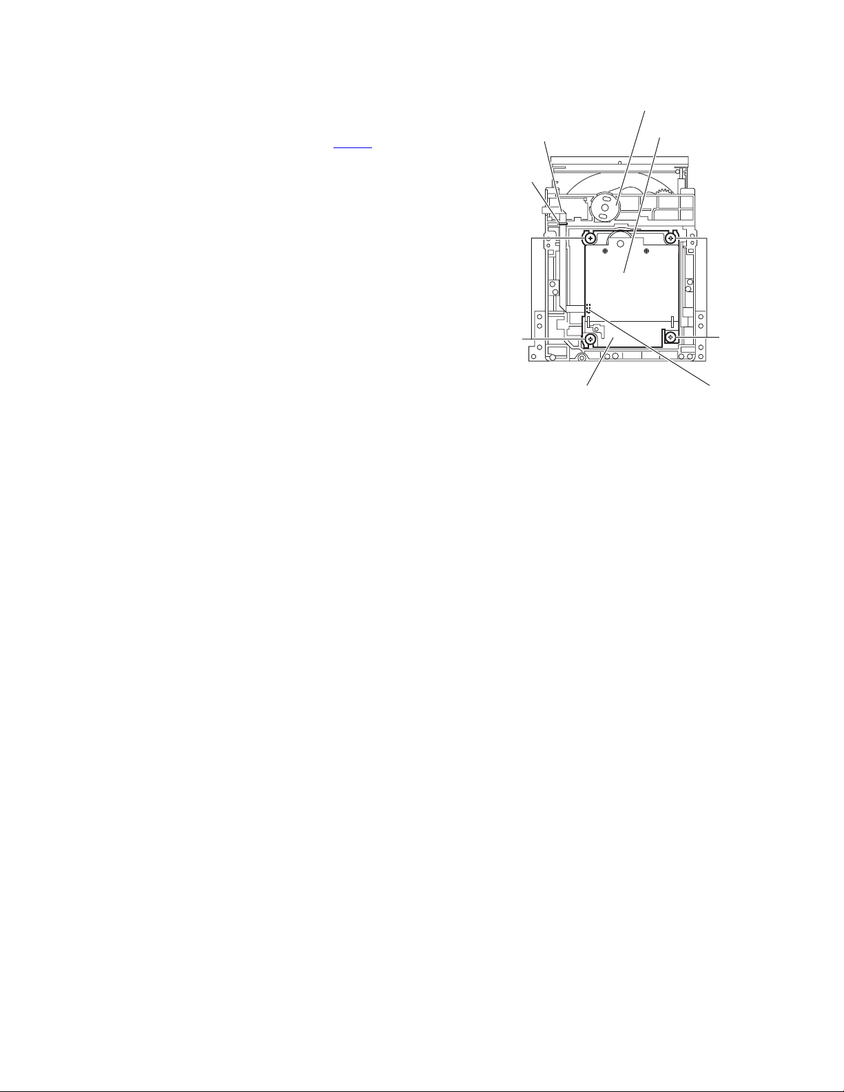
3.2.3 Removing the traverse mechanism assembly
(See Fig.4)
(1) Remove the four screws C attaching the traverse mecha-
nism assembly from bottom side of CD mechanism assembly.
(2) Disconnect the card wire from connector CN602
servo board and then take out the traverse mechanism assembly and CD servo board together.
Reference:
When reattaching the traverse mechanism assembly, the card
wire should through the part d.
of the CD
Card wire
d
CD mechanism assembly
CD servo board
C
Traverse mechanism assembly
Fig.4
C
CN602
(No.MB664<Rev.002>)1-15
Page 16

3.2.4 Removing the CD servo board
(See Fig.5 and 6)
• Remove the traverse mechanism assembly.
(1) Remove the two screws D attaching the CD servo board
from bottom side of traverse mechanism assembly. (See
Fig.5)
(2) Remove the solder from solder part e of the CD servo
board. (See Fig.5)
(3) Remove the yellow wire from solder part f of the CD servo
board. (See Fig.5)
(4) Remove the white wire from solder part g of the CD servo
board. (See Fig.5)
(5) Remove the CD servo board to upper side, disengage the
hook c to direction of the arrow 1 then turn over the CD ser-
vo board. (See Fig.5)
(6) Solder to short land part j of pickup. (See Fig.6)
(7) Release the lock of connector CN601
row 2 and disengage the card wire. (See Fig.6)
Caution:
• Solder to short land part j of the pickup then disconnect the
card wire from connector CN601
disconnect the card wire before soldering, pickup is make
sure destroyed by static electricity. (See Fig.6)
• When reattaching the CD servo board, connect the card wire
to connector CN601 and then remove the solder of short
land part j of the pickup.
to direction of the ar-
of the CD servo board. If
CN601
Hook c
Solder part e
1
CD servo board
Traverse mechanism assemblyCD servo board
Fig.5
DD
Yellow wire
White wire
1
Hook c
Solder
part f
Solder
part g
Pickup
Short land part j
CN601
22
Traverse mechanism assembly
Fig.6
1-16 (No.MB664<Rev.002>)
Page 17
3.2.5 Removing the pickup
(See Fig.7 to 9)
• Remove the traverse mechanism assembly.
(1) Remove the one screw E attaching the plate from upper
side of traverse mechanism assembly. (See Fig.7)
(2) Remove the plate from fixing part k then take out the plate.
(See Fig.7)
(3) Remove the two screws F attaching the LEAD spring and
then take out the LEAD spring. (See Fig.8)
(4) Take out the feed gear, and then remove the shaft of pick-
up from part m of the traverse mechanism assembly. (See
Fig.8)
(5) Remove the pickup from part n of the traverse mechanism
assembly and then take out pickup with shaft. (See Fig.8)
(6) Release the shaft from pickup. (See Fig.8)
(7) Solder the short land part p of the pickup. (See Fig.9)
(8) Release the lock of the connector to direction of the arrow,
and then disconnect the card wire. (See Fig9)
Caution:
• Solder to short land part p of the pickup then disconnect the
card wire from connector. If disconnect the card wire before
soldering, pickup is make sure destroyed by static electricity.
(See Fig.9)
• When reattaching the pickup, connect the card wire to con-
nector and then remove the solder from short land part p.
(See Fig.9)
Feed gear Shaft LEAD spring
Pickup
Short land part
p
F
Part n
Fig.8
Part m
3.2.6 Attaching the pickup
(See Fig.7 to 10)
• Please refer the "Removing the pickup".
(1) Connect the card wire to connector of pickup, and then re-
move the solder from short land part p of the pickup. (See
Fig.9)
(2) Attach the shaft to pickup. (See Fig.8)
(3) Fit the pickup to part n of the traverse mechanism and then
attach the end of the shaft to part k. (See Fig.8)
(4) Attach the LEAD spring and feed gear. (See Fig.8)
(5) Attach the plate. (See Fig. 7)
(6) One turn the LEAD gear to direction of the arrow 1 and fully
shift to direction of the arrow 2. (See Fig.10)
Plate
Fixing part k
E
Pickup Connector Card wire
Fig.9
LEAD gear
1
2
Traverse mechanism assembly
Fig.10
Pickup
Traverse mechanism assembly
Fig.7
(No.MB664<Rev.002>)1-17
Page 18
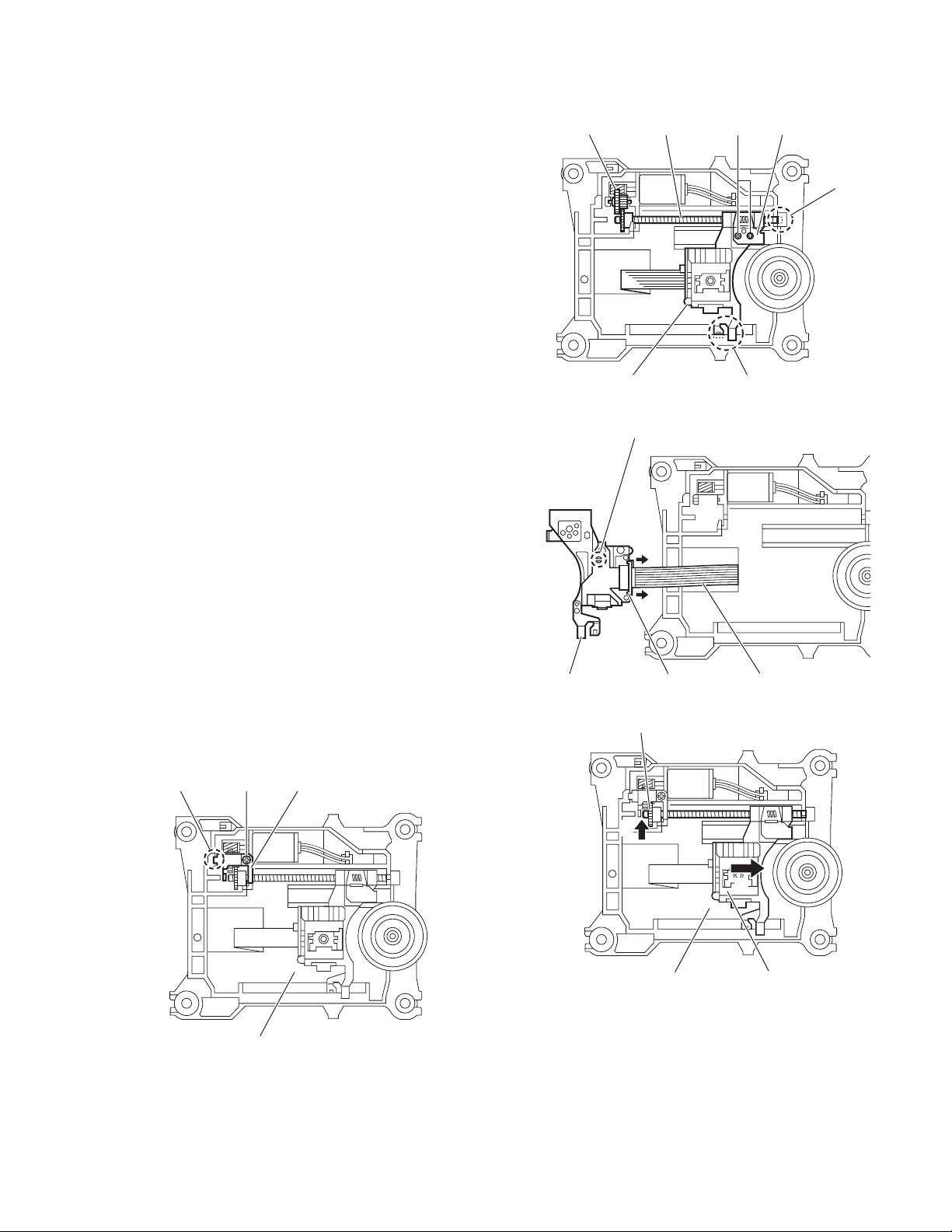
3.2.7 Removing the feed motor
(See Fig.11 to 13)
• Remove the traverse mechanism.
(1) Remove the yellow wire from solder part q of the CD servo
board from upper side of traverse mechanism. (See Fig.11)
(2) Remove the white wire from solder part r of the CD servo
board. (See Fig.11)
(3) Remove the one screw G attaching the plate. (See Fig.12)
(4) Disengage the plate from fixing part s and take out the
plate. (See Fig.12)
(5) Remove the feed gear and take out the feed motor. (See
Fig13)
Reference:
When attaching the feed motor, the wire has to through the
part t of the traverse mechanism assembly. (See Fig.13)
Yellow wire
White wire
Soldered part q
Soldered part r
Feed gear Feed motor
Traverse mechanism assembly
Fig.13
part
t
Fixing part s
Traverse mechanism assembly
G
Traverse mechanism assemblyCD servo board
Fig.11
Plate
Fig.12
1-18 (No.MB664<Rev.002>)
Page 19
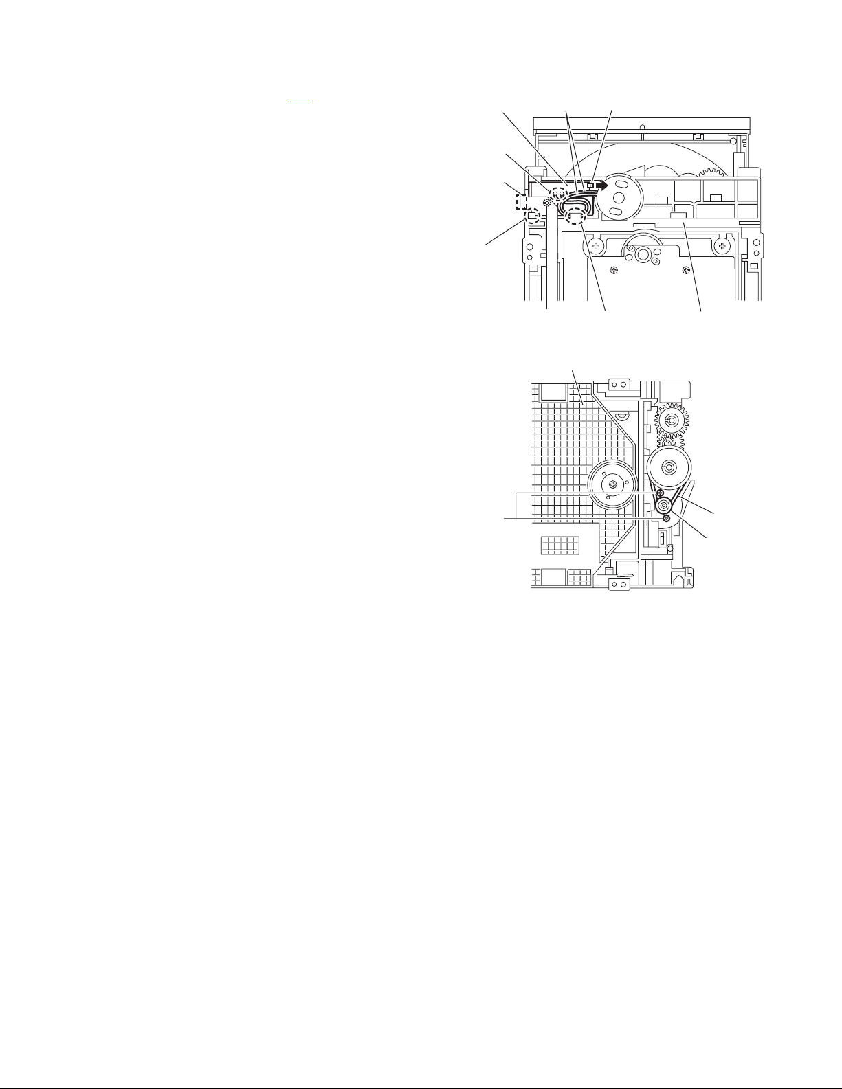
3.2.8 Removing the switch board
(See Fig.14)
(1) Disconnect the card wire from CN1
from bottom side of CD mechanism assembly.
(2) Remove the wire from solder part u of the switch board.
(3) Remove the one screw H attaching the switch board to CD
mechanism assembly.
(4) Lift up the switch board by pushing the hook v of CD mech-
anism assembly and take out it from part w.
Reference:
• After attach the switch board to CD mechanism assembly,
wire hooked to part x.
•Hook u of the CD mechanism assembly, it have to bond
lock.
3.2.9 Removing the motor
(See Fig.14 and 15)
• Remove the tray assembly.
(1) Remove the wire from solder part u of the switch board
from bottom side of CD mechanism assembly.
(2) Remove the belt of motor pulley from upper side of CD
mechanism assembly. (See Fig.15)
Caution:
Belt should not apply grease.
(3) Remove the two screws J attaching the motor to CD mech-
anism assembly and take out the motor from bottom side
of CD mechanism assembly. (See Fig.15)
Reference:
After motor attached to CD mechanism assembly, wire should
hook to part w. (See Fog.14)
of the switch board
Switch board Wire
Solder
part u
CN1
Part w
H
CD mechanism assembly
J
Hook v
Part x
CD mechanism assembly
Fig.14
Belt
Fig.15
Motor pulley
(No.MB664<Rev.002>)1-19
Page 20

4.1 Outline
4.2 How to go CD TEST MODE
[SET] + [POWER] + AC in
4.3 Function specification
SECTION 4
ADJUSTMENT
CD TEST MODE
C1 error display
Function
CD TEST MODE
C1 error display
C1 error display
Return to CD TEST MODE
4.4 C1 error history
When 8 key is pressed, syscon send C1 err display command (0x9C 0x01 0x00).
If syscon receive C1 error display status (0xAA 0x01 0x00 ** **), it displays C1 error.
Syscon convert 2byte hex data to decimal data (00000-65635).
4.5 Special mode
[STOP] + [POWER] + [ 0 ] : COLD SET
[STOP] + [POWER] + [ 1 ] : FL DISPLAY turn on all segment
[STOP] + [POWER] + [10] :Micom version display (Mecha version, Destination, Syscon version)
Exsample In case of " 2501 JC241"
Mecha version: 25
ROM corr: 1
Destination: JC
Syscon version: 24
Syscon corr: 1
Key Operation FL display
CD TESTT
8
CANCEL
Remocon
Remocon After receive data
Remocon
INITIAL
Er
CD TESTT
*****
1-20 (No.MB664<Rev.002>)
Page 21

SECTION 5
TROUBLESHOOTING
This service manual does not describe TROUBLESHOOTING.
(No.MB664<Rev.002>)1-21
Page 22

Victor Company of Japan, Limited
Audio/Video Systems category 10-1,1chome,Ohwatari-machi,Maebashi-city,371-8543,Japan
(No.MB664<Rev.002>)
Printed in Japan
VPT
Page 23

SCHEMATIC DIAGRAMS
COMPACT COMPONENT SYSTEM
MX-KC68J, MX-KC68C, MX-KC68B,
MX-KC68E, MX-KC68EN, MX-KC68EV,
MX-KC68A, MX-KC68UJ, MX-KC68UW,
MX-KC38J, MX-KC38C
DVD-ROM No.SML2008Q2
SP-MXKC68W
SP-MXKC68F
SP-MXKC38
SP-MXKC68F
SP-MXKC38
CA-MXKC68
CA-MXKC38
(MX-KC68B,E,EN,EV)
Lead free solder used in the board (material : Sn-Ag-Cu, melting point : 219 Centigrade)
Lead free solder used in the board (material : Sn-Cu, melting point : 230 Centigrade)
Contents
Block diagrams
Standard schematic diagrams
Printed circuit boards
COPYRIGHT 2008 Victor Company of Japan, Limited.
2-1
2-2
2-8 to 10
No.MB664SCH<Rev.002>
2008/8
Page 24

In regard with component parts appearing on the silk-screen printed side (parts side) of the PWB diagrams, the
parts that are printed over with black such as the resistor ( ), diode ( ) and ICP ( ) or identified by the " "
mark nearby are critical for safety.
Page 25

Block diagram
FL900
LCD DISPLAY
IC910
REMOCON
S9051 to S9057
KEY MATRIX
D9200,Q9201
STANDBY LED
D9254,D9255,Q9251
ILLUMINATION LED
S9221 to S9227
KEY MATRIX
JS920
VOLUME
HPSW
J950
HEAD
PHONE
HP_L/R
HP Jack
J940
AUX IN
AUXIN AMP
AUX Jack
IPOD-TX, IPOD-RX, DGSEN
IPOD-PWR
CN912
IPOD
IPOD-L
IPOD-R
AUDIO-RETURN
Front panel section
SPINDLE
MOTOR
FEED
MOTOR
CD
M
M
CN101
traverse
& pickup
mechanism
SW601
REST SW
FLDATA
G1 to 12
S1 to 16
FL+/-
REMOCON
IC901
LCD
DRIVER
FLSTBY
FLCLK
-VDISP
LCD,Key switch
KEY2
STBYLED
KEY1
& Remocon
ILLUMILED
Key switch,LED & Volume
VOL+/-
FW920
CN951
HPSW
HP_L/R
IC940
AUXIN_L/R
AUX_SW
IPOD Jack
CD servo control section
SM+/-
FM+/-
F+/T+/-
PSW
IC201
CD
DRIVER
TRVP, SPOUT
TRP, FOP
MUTE
VF1, VF2
VT1, VT2
LD, MD
X301
16.9344MHz
CN901
CN700
CN920
CN701
FW941
CN705 CN702
CN914
IC301
Q301
CPU/CD RF
&
SERVO/DSP
System control section
FL+/-
-VDISP
FLDATA
FLSTBY, FLCLK
REMOCON, KEY2
3.1V D5V
Q700
3.1V SW
STBYLED
ILLUMILED
KEY1
VOL+/HP_SW
HP_L/R
IC330 to IC332,Q3408
HEADPHONE AMP & MUTE
AUXIN_L/R
AUX_SW
IPOD_TX, IPOD_RX, DGSEN
IPOD-PWR
IC750
IPOD-PWR REG.
IPOD_OUTL
IPOD_OUTR
AUDIO_RETURN
IC310
IPOD CCT
Loader
section
LOADING MOTOR
UCS, SCS
U2SDT, S2UDT
UCLK, NRST
CDL, CDR
SCL
SDA
S1
TRAY SWITCH
IC302
EEPROM
IC304
D4V3.3V
M
3.3V
REG.
X7100
8MHz
HP_MUTE
D5V
IPOD_L
IPOD_R
OPSW, CLSW
CN709
CN1
M+/-
CN701
CN708
D4V
IC700
MICON
IC740
EEPROM
IPOD_PON
IPOD_SAFETY
IC730
MOTOR
DRIVER
UCS, SCS
U2SDT, S2UDT
SCLK, CDRESET
Q7301,Q7302
CD SW
CDL, CDR
EEP_WP
EEP_CLK
EEP_DAT
TOPEN
TCLOSE
Q7201
RESET
D4V
CD_PWR
RESET
AHB
SAFETY1
A9V_SAFETY
AMP_L
AMP_R
IC342,IC362
AHB
FEEDBACK
AMP_ON, AMP_MUTE
Q7600 to Q7602
SAFETY REG.
Regulator section
A9V
IC791
12V
A9V REG.
SPI_L
SPI_R
IC341
AHB1
IC360
AHB2
-VDISP
FL+/-
M9V
D5V
D4V
12V
VOL_CLK
VOLDA
Q3000
Q3001
OUT_L
OUT_R
SWLEV1
SWLEV2
SMUTE
Q701,Q702
D7907
D7906
D7902
D7910
D7904
D7903
IC300
E.VOLUME
IC350,Q3500 to Q3502
Q3504,Q3505
SW AMP & MUTE
Q3608
SMUTE
IC361
MAIN MUTE
LEVEL_DET, AMP_OSC (FHOP)
AHB_FEEDBACK
AMP_CTRL (MODE)
IC792
Q7901
Q7902
T700
SW REG.
POWER
D6V
TRANS.
REG_ON
(SYSPON)
TEMP, SYS_PON, SYNC, H/L
TUL/R
REG_SW
SW_IN
L_IN
R_IN
+28V
B3.3V
FAN_CTRL
FAN_ST
TU_CE, TU_CLK, TUOUT, DATA_IN, TUAMSW
RDS_CLK, RDS_DAT
Q7501,Q7502,Q7505
FAN DRIVE
Power amp section
Used for MX-KC68
LEV_DET
D5802
LEVEL DETECTION
SW_IN
IC501
SUBWOOFER
POWER AMP.
IC560,IC561
FHOP
CN502 CN501
Q5600
X5601,X5602
600/700kHz
OSC
CLOCK GEN.
CN704CN301
LEV_DET
AHB_FB
DC_DETDC_DETECT
+28V
SYSPON
L_IN
R_IN
MODE
RY510,RY520
IC510
L/R
POWER AMP.
IC570,D5801,D5901
DC DETECTION
LEVEL DETECTION
AHB CONTROL
VDDP
VSSP
Q5100
Used for Area suffix UJ/UW
RELAY
+/-28V
FW500
FW700
POWER UNIT
SUB+/-
L
R
J5555
VOLTAGE
SELECTOR
FW555
FAN
M
MOTOR
CN707CN706
TUNER
PAC K
SUBWOOFER
J5100
SPEAKER
LEFT/RIGHT
AC IN
2-1
Page 26

Standard schematic diagrams
Pre-amp section
GND
GND
-28
1
2
FW500
3
4
QJK015-041014PP
28.2V
0V
0V
-28.8V
+28
NI
C5973NIC5972NIC5971
-28.8V -28.8V
NI
NI
NI
PP503
PP502
RY510
QSK0194-001
11.5V
13
28.2V
0V
2 4
28.2V
R5999
82
1/4W
!
!
FRFR
R5889
R5888
47
47
1/4W
1/4W
0V
0V 0V
D5120
MA111- X
2.9V
13
11.5V
MA111- X
Q5100
KRC101S-X
SYSPON
D5130
KRC101S-X
Q5600
22
R5601
D5601
MA111- X
D5602
R5602
MA111- X
1M
R5606
1.5K
R5607
1.5K
C5608
C5607
47P
47P
100P
C5611
22
R5611
QAX0937-001
QAX0936-001
C5601
0.01
C5602
0.01
C5603
100P
X5601
C5604
100P
C5605
100P
X5602
C5606
100P
D5131
MA111- X
RY520
QSK0194-001
2 4
R5600
10K
1M
R5603
IC560
74HCU04PW-X
5.2V
1
1A
0V
2
1Y
2.4V
3
2A
2.5V
4
2Y
4.8V
5
3A
0V
6
3Y
0V
GND74Y
IC561
HEF4013BTT-X
2.7V
1
O1
0V
2
O1
2.6V
3
CP1
0V
4
CD1
0V
5
D1
0V
6
SD1
0V
GND7SD2
PGND
B5601
K5601
NI
0.1
C5609
100/16
C5610
5.2V
14
VCC
5.2V
13
6A
0V
12
6Y
2.4V
11
5A
1M
R5604
2.6V
10
5Y
2.6V
9
4A
2.6V
8
100
R5605
5.2V
14
VCC
0V
NC
13
O2
C5612
0.1
0V
12
NC
O2
0V
11
CP2
0V
10
CD2
0V
9
D2
0V
8
PP501
1
1
1
C5001
0.1
C5005
2200/35
R5007NIR5008
QQR0621-001Z
K5001
C5009
470/35
10
R5001
VSSP
VSSA2
EP502
GVA10163-A1
C5002
0.1
C5006
2200/35
NI
K5002
QQR0621-001Z
C5010
470/35
VDDP
VDDP
R5002
VDDA2
C5012
C5011
470/35
470/35
10
10
R5003
VSSA1
10
R5004
VDDA1
MODE
27.8V
0V
OSC1IN1P2IN1M3VDDA14SGND15VSSA16PROT7VDDP18BOOT19OUT110VSSP111STABI12VSSP213OUT214BOOT215VDDP216VSSD17VSSA218SGND219VDDA220MODE23IN2P22IN2M
2.7V
0.1
C5106
220p
C5101
0.47
0.47
C5103
C5102
5.6k
5.6k
R5101
R5102
NI
C5104
NI
C5105
27.8V0V0V
2.7V
OSC1IN1P2IN1M3VDDA14SGND15VSSA16PROT7VDDP18BOOT19OUT110VSSP111STABI12VSSP213OUT214BOOT215VDDP216VSSD17VSSA218SGND219VDDA220MODE23IN2P22IN2M
0.1
C5306
220p
C5301
0.47
C5303
0.47
C5302
5.6k
5.6k
R5301
R5302
NI
C5304
NI
C5305
TDA8920B/N2
IC510
2.03V
2.03V
12.9V
28.2V
0V
0.1
C5107
0.1
C5110
0.1
C5112
0V
0.1
C5307
C5310
0.1
C5312
47/63
C5313
-16.5V
-28.7V
-20.4V0V-28.5V
0.1
C5116
C5209
C5108
220p
0.015
C5109
1M
R5199
0.1
0.1
C5211
C5111
10
R5103
0.1
C5212
C5113
47/63
470p
C5114
TDA8920BJ/N2
IC501
2.03V
12.9V
28.2V
-16.5V
-28.7V
-20.4V
-28.5V
0.1
C5316
C5308
220p
0.015
C5309
1M
R5399
0.1
0.1
0.1
C5411
C5311
10
R5303
0.1
C5412
470p
C5314
0V
28.2V
12.9V
-28.7V
-28.5V
-28.5V
0.015
C5207
0.1
1M
R5299
0.1
C5202
C5210
10
R5203
470p
C5214
2.03V
0V
28.2V
12.9V
-28.7V
-28.5V
-28.5V
C5407
0.1
0.015
C5409
1M
R5499
0.1
C5410
10
R5403
470p
C5414
C5092
NI
27.9V
0V
0V
2.6V
21
C5091
NI
C5089
NI
220p
C5201
0.1
C5206
0.47
5.6k
R5201
NI
C5204
0V0V27.9V
21
0.1
C5406
220p
C5401
D5398
MA111- X
L5101
D5198
MA111- X
QQR1820-001
100
L5201
QQR1820-001
L5301
QQR1820-001
L5401
QQR1820-001
1W
22
R5128
0.68
C5127
0.1
C5128
0.1
C5228
0.68
C5227
22
R5228
1W
1W
22
R5348
0.68
C5327
0.1
C5328
0.1
C5428
0.68
C5427
22
R5428
1W
C5198
10/50
R5198
C5203
0.47
5.6k
R5202
NI
C5205
2.6V
R5398
100
C5398
10/50
R
EP501
NI
L
C5093
0.1
0.1
0.1
8
C5094
C5095
C5096
0.1
C5097
L
6
5
4
R
3
J5100
2
SUB-
QNB0315-001
1
SUB+
7
0.1
0.1
C5098
C5099
FOR MX-KC68 ONLY
CN501
QGB2510J1-08
SUBWIN
K5611
D5V
SWGND
SUBWIN
D5V
AHB_FB
0V0V0V
0V
L-IN
AGND
MODE
LEV_DET
FHOP
2.7V
0V
0V
0.2V
0V
987654321
R-IN
SW-GND
SW-IN
AHB-FB
MODE
FHOP
LEV-DET
DC_DET
5.2V
2.9V
3.3V
0V
28.2V
13.2V
0V
0V
1
AGND
DC-DET
8765432
D5V
+28V
REGGND
MGND
SYSPON
12V
QGB2510J1-09
CN502
QQR0621-001Z
D5V1
100K
100K
R5701
82K
R5702
R5703
82K
0V
0V
321
0V
3.3V
NI
D5701
Parts are safety assurance parts.!
When replacing those parts make
sure to use the specified one.
LEV_DET
R5704
82K
R5902
82K
R5901
NI
B591
B592
C5901
C5902
47/25
47/25
7.5K
R5903
C5903
C5904
7.5K
NI
NI
R5904
0V0V
1
3
MC2838-X
D5901
2
0V
20K
R5808
1
MC2838-X
D5802
FOR MX-KC68 ONLY
0.2V
LEVEL DETECTION
*
REF. NO.
MODEL
R5805
R5806
MX-KC68MX-KC38
20K
15K
20K
15K
20K
R5806
20K
*
R5807
3
2
47K
C5805
47/25
R5809
D5803
MA8033/H/-X
0V 0V0V 0V
MC2838-X
D5801
20K
R5805
*
3
1
2
0.2V
R5705
C5701
ERR
1K
100K
10/50
R5706
DC DETECTION
3.3V
6 5 4
IC570
RT3CLLM/EF/-X
0V
2-2
Page 27

Micom section
*
REF. NO.
*
REF. NO.
CN700
QGF1208C1-11
3.3V
REMOCON 1
3.3V
B3.3V 2
0V
DGND 3
3.3V
KEY2 4
0V
FLDATA 5
-27.7V
-VDISP 6
3.3V
FLCLK 7
-20.7V
FL- 8
0V
FLSTBY 9
-25.1V
FL+ 10
3.1V
D5V 11
CN701
QGF1208C1-13
0V
HP_L 1
0V
HP_GND 2
0V
HP_R 3
0.3V
HP_SW 4
3.3V
B3.3V 5
NC 6
5.3V
D5V 7
3.3V
KEY1 8
0V
DGND 9
0V
STBYLED 10
3.3V
ILLUMILED 11
0V
VOL+ 12
3.3V
VOL- 13
CN702
QGA2001C1-08
0V
IPOD-R
8
0V
AUDIO-RETURN
7
0V
IPOD-L
6
3.3V
DGSEN
5
5V
IPOD-PWR
4
1.8V
IPOD-TX
3
3.3V
IPOD-RX
2
0V
DGND
1
CN705
QGD2504C1-05Z
3.3V
AUX_SW
5
4.5V
AUXIN_R
4
0V
AUX_GND
3
4.5V
AUXIN_L
2
9V
A9V
1
TX9
D4V8
D4V7
4.2V
C7308
B7003
SPI_R
0V
H/L
DGND6
0V
B7002
100/16
330R7089
TEMP 89
SPI_R 90
R7043
MA8043/M/-X
CDL2
CDR4
AGND3
DGND5
LRMUTE1
NI
R7306
3.3V
0V
0V
C7305
C7303
OPSW
330 R7045
DGSEN
0V 2.6V
1.6V
33/63
C7304
0.0033/50
0.0033/50
CLSW
CLSW 85
OPSW 86
Q7600
KRC102S-X
0V
K7601
NI
B7601
C7306
33/63
CDRESET
330
330
R7083
R7084
3.3V
CDRESET 84
R7048
R7047
330
330
AUX_SW
SCS
330R7082
3.3V
3.3V
SCS 83
0.3V0V3.3V0V3.3V
R7049
330
HP_SW
IPOD_PON
680R7302
680R7303
R7304
330R7081
1.1V
TUAMSW 82
RDS_DAT 81
DATA_OUT
RDS_CLK
FAN_CTRL
VOL_CLK
REG_SW
DC_DETECT
AMP_OSC
AMP_MUTE
BEATCUT
SYS_PON
SAFETY_REG
HP_MUTE50HP_SW49IPOD_PON48AUX_SW47NC46DGSEN45VOL-44VOL+43NC42NC41ILLUMILED40STDBYLED39IPOD_SAFETY
0V
R7050
330
HP_MUTE
D7604
D7605
D7606
D7607
MA8082/M/-X
MA111- X
12K
CDL
TU_CE
TU_CLK
DATA_IN
FAN_L
FAN_ST
VOLDA
SWLEV3
SWLEV1
SWLEV2
MODEL
SMUTE
REG_ON
AMP_ON
D7609
C7307
12K
NI
R7305
CDR
6 5 4
NI
IC731
CD MUTE
R7186
10K
10KR7185
0V
80
0V
79
0V
78
3.9V
77
0V
76
1.3V
75
0V
74
3.3V
73
3.3V
72
3.3V
71
3.3V
70
0V
H/L
69
0V
68
0V
AHB
67
0V
66
0V
65
0V
GND
64
3.3V
63
3.3V
VCC
62
0V
61
3.3V
60
0V
59
3.3V
SYNC
58
0V
57
2.1V
56
3.3V
55
0V
54
3.3V
53
R7052
2.5V
52
330
0V
NC
51
10KR7142
10KR7143
10KR7144
10KR7147
10KR7149
REG_ON
SAFETY1
1
MC2836-X
2.6V
D7601
NI
3
2
9V
4.2V
NI
NI
CDR
R7080
R7079
R7078
R7077
R7075
R7074
R7072
R7071
R7068
R7067
R7066
R7065
*
*
R7061
R7059
R7058
R7057
R7053
R7152
SAFETY1
3
13.2V
D7302
IN4003S-T5
R7312
18K
NI
R7311
CDL
KTA1271/OY/-T
0V
0V
R7310
1K
3.3V
Q7302
KRC102S-X
321
D7089
MA8033/M/-X
330
330
330
330
NIR7076
330
330
R7173
330R7043
10K
330
330
R7172
330R7070
10K
330R7069
NI
330
330
330
C7104
0.01
R7164
R7162
330
330R7060
330
330
330
330R7056
330R7055
330
10K
B7600
1
2.6V
D7602
2
MC2836-X
6V
3.2V
Q7902
KRC102S-X
R7160
10K
NI
K7600
2.6V
Q7601
KRC102S-X
0V
0V
0V
Q7602
0V
KRA102S-X
SK14-GA-X
Q7301
10K
SAFETY_CD
NI
3.4V4.1V
4.2V
47K
R7309
10K
R7170
0V0V
DC_DETECT
R7600
10K
-27.4V
D7920
NI
D7303
CD_PWR
LEVEL_DET
TEMP
TU_CE
TU_OUT
TU_CLK
DATA_IN
RDS_CLK
SWLEV3
SWLEV2
SWLEV1
DC_DETECT
AMP_OSC
SYNC
REG_ON
AMP_ON
AMP_MUTE
SYS_PON
TU_OUT
TU_CLK
DATA_IN
RDS_CLK
CDL
CDR
IPOD_OUTL
H/L IPOD_OUTR
AHB
SWLEV3
AHB
SWLEV1
SWLEV2
SPI_L
SPI_R
HP_MUTE
AUXIN_R
AUXIN_L
DC_DETECT
LEVEL_DET
AMP_OSC
AMP_ON
AMP_MUTE
HP_L
HP-GND
HP_R
REG_ON
REG_ON
C7914
NI
C7913
E409182-001SM
TU_CE
NI
EP700
FOR E-VERSION
R770
NI
C770
NI
D770
MA8033/H/-X
B7005
Q7505
R7501
KTC3203/0Y/-T
13.3V
13.3V 0.3
10
13.3V
Q7501
Q7502
0V
Q7901
KRC102S-X
0V
R7502
R7504
0V
VOLDA
VOL_CLK
R7901
10K
13.3V
NI
KRC102S-X
T700
R7902
0
1.5k
KRA102S-X
0.5V
820
R7503
MA8068/M/-X
D7501
MA8120/M/-X
Q7504
KRC102S-X
R701
1K
0V.
Q701
3.2V
-24.6V
1
6V
6.3V
R7903
200
D7905
C7903
FMB-24
680/25
1N4003S-T5
2.7V
0V
8
2
SK14-GA-X
D7910
0.5V
220
D7502
NI
NI
Q7503
RT1N141C-X
3
6V
D6V
100
R7904
D7909
NI
NI
0V
0V
SK14-GA-X
-24.8V
D7902
R702
Q702
D7906
9
6.1V
R7505
C7501
820
KRC102S-X
C7915
4
SK14-GA-X
MA111-X
C7502
D7503
47/25
100/16
AMP_CTRL
100P
NI
7V
10
6.3V
D7903
C7905
680/25
C7904
680/25
C7908
D7907
39/35
FR104S
0V
11
5
12VM9V
7
6
1.7V
D7904
SK14-GA-X
D4V
1K
5.1K
R7090
R7099
C7906
680/25
FAN
DRIVER
KRC103S-X
HS792
IC792
SI-8050S
6.3V27.7V
2
1
543
2.4V
5V
0V
2.4V
0V
C7901
C7900
470/50
NI
C7902
10000p/50
R771
51K
R776
51K
B7006
C7907
82/16
Q7903
2SA1530AC1/QR/-X
-VDISP
3.3K
R7905
NI
D7911
MA8270/M/-X
PQ090RDC1SZF
13.2V
NI
R772
B7101
FL+
FL-
9V
51K
R773
51K
R774
51K
R775
51K
0.2V
0V
3.3V
C7917
C7916
IC791
A9V
*
CN707
1
3
5
7
9
CN706
QGA2501C1-03
1
2
3
TUR
TUL
CDL
CDR
VOLDA
VOL_CLK
IPOD_OUTL
IPOD_OUTR
AUDIO_RETURN
SMUTE
SWLEV3
AHB
SWLEV1
SWLEV2
SPI_L
SPI_R
HP_MUTE
AUXIN_R
AUXIN_L
DC_DETECT
LEVEL_DET
AMP_OSC
AMP_CTRL
MA8024-X
B7005
NI
0.1
0.1
NI
0V
TUCE
0V
TUDOUT2
0V
TUCLK
0V
TUDIN4
4V
TUGND
0V
TUL6
0V
9V
9V
TUR8
0V
NC
NC10
TUGND11
0V
3.3V12
3.3V
TUAMSW13
3.3V
RDS_CLK14
1.3V
RDS_DAT15
1.1V
D7908
4321
*
CN707
PART U SEVERSION
QGF1208C1-15
B,E,EN,EV
QGF1208C1-11
OTHERS
FAN
AGND
A9V
B3.3V
HP_L
HP-GND
HP_R
C7909
22/50
R7906
22K
NI
2.9V
C7912
100/16
1.6V
NI
K7300
330
330
R7088
R7087
0V0V0V
TOPEN 88
TCLOSE 87
0V0V0V
3.3V
R7044
330
330
VOL-
VOL+
D7608
SCS17
M9V13
UCS18
CLSW1
CLSW
TRAY LOADER DRIVER
1
C7301
MA8047/M/-X
R7094
R7095
R7097
10K
R7194
2.7V
3.3V
0V
0V
0V
3.3V
0V
0V
0V
3.3V
3.3V
0V
3.3V
3.3V
0V
10K
0V
330
0V
330
0V
330
0V
0V
0V
3.3V
330
3.3V
1.8V
10KR7130
NI
NI
NI
TXD
RXD
EEP_WP
EEP_CLK
100
0V0V0V
6WP7
8
VCC
A01A12A23GND
0V0V0V
0.7V
D7300
330
330
EEP_DAT
SCL
SCLK
5
4
0.01/50
0V0V
CN708
IC730
LB1641
1
2
3
4
5
6
7
8
9
10
11
12
13
14
15
16
17
18
19
20
21
22
23
24
25
26
27
28
29
30
SDA
0.5V
C7094
BUSY
0.01
SAFETY_CD
CD_PWR
NC
NC
NC
NC
NC
BYTE
CNVSS
XCIN
XCOUT
RESET
XOUT
GND
XIN
VCC
NC
INH
UCS
REMOCON
NC
CB TEST
EEP_DAT
EEP_CLK
EEP_WP
NC
NC
A9V_SAFETY
IPOD_RX
IPOD_TX
CDRESET19
3.3V
3.3V
QGF1040C1-19
UCS
CDRESET
0V0V0.6V
0V
330
R7031
EPM
CE
R7205
100k
EEP ROM
IC740
S-24CS04AFJ-G-X
M-4
M+5
MGND3
C7204
10/50
CN709
QGF1040C1-05
VCC
RESET
0.6V
M+
R7197
CNVSS
EEP_DAT
10K
330
330
C7205
0.6V
M-
EEP_CLK
NI
0.01/50
0V0V0V
MGND
0.1/16
KEY2
KEY1KEY1
10K
R7195
R7017
R7019
R7020
R7122
R7023
R7024
R7025
R7028
R7029
R7030
EEP_WP
OPSW2
OPSW
C7300
10K
330
330
R7131
R7132
R7133
R7204
MODEL
R7162
R7164
VERSION
R7300
C7406
C7405
0.1
C7407
0.1
C7402
0.1
C7403
100P
C7404
100P
MX-KC68MX-KC38
10K
NI
NI
10K
UJUWB,E,EN,EVAJ,C
3.3K10K
NIR7301
0.1
K7405
K7407
K7404
K7406
K7400
K7401
K7402
K7403
K7400-K7407
USED B/W
8.2K15K
10K10K10KNI10K
REMOCON
FLDATA
FLCLK
FLSTBY
22/50
3.1V
Q700
5.2V
KTC3265/Y/-X
IC750
MM3235AF-X
1
NC
2
VDD
5V6V0V
3
Vout
4
NC
REMOCON
0V
3.3V
3.3V
0V
0V
0V
0V
0V
0V
3.3V
0V
C701
3.8V
270
R700
GND
CE
AC OFF
DETECT
RESET
0.01
NC
0V
CE
NC
EPM
D700
MA8039-X
BUSY
C702
C700
22/50
8
7
6
5
IPOD_PON
CD_PWR
SAFETY_CD
TXD
RXD
SCLK
C7200
100/16
R7202
NI
NI
R7206
10k
C7202
4.7/50
D7201
MA111- X
X7100
QAX0711-002Z
8MHz
C7100
22P/50
UCS
D7200
NI
0V
3.3V0V
NI
Q7201
KRC102S-X
C7101
IPOD_RX
R7201
NI
IPOD_TX
Q7200
0.01/50
10K
R7101
22P/50
NI
A9V_SAFETY
C7203
XOUT
XIN
0.01
C7102
C7103
100/16
R7128
10K
INH
INH
RESET
C7201
0.01
HP_L
HPGND
HP_R
HP_SW
KEY1
IPOD_OUTR
IPOD_OUTL
DGSEN
C7410
0.1
C7408
0.1
IPOD_TX
R7400
IPOD_RX
1K
100p
C7409
AUX_SW
AUXIN_R
AUXIN_L
R7401
B3.3V
IPOD_SAFETY
NI
B7118
C7413
100/16
C7414
1
10K
C7411
100/16
C7412
1
CN703
QGF1208C1-11
NC 11
VCC 10
SCLK 9
RXD 8
TXD 7
BUSY 6
EPM 5
CE 4
CNVSS 3
RESET 2
VSS 1
M9V12
UCLK16
MGND11
MGND10
S2UDT15
U2SDT14
0V
0V
4.2V
9.1V
9.1V
3.3V
3.3V
3.3V
3.3V
B7001
NI
D7304
K7301
NI
U2SDT
S2UDT
UCLK
SCS
SPI_L
0.7V
7.9V
7.9V
M-10P29VCC28VCC17IN-6IN+5VZ4P13M+2MGND
0.6V
D7301
1N4003S-T5
C7302
100/16
C7095
R7300
0.01
*
C7097
0.01
330
R7301
R7092
*
3.3V
0V
0V
3.3V
3.3V
3.3V
3.3V
0V0V0V
0.2V
94
R7034
FLSTBY
92
KEY1 97
KEY2 95
KEY3
SPI_L 91
AD_GND 96
VERSION 93
LEVEL_DET
IC700
M3030RFAPFP
UCLK37U2SDT36S2UDT35FLSTB34FLCLK33NC32FLDATA
38
3.3V0V3.9V
3.3V
3.3V
3.3V0V3.3V
330
330
330
R7035
R7040
R7039
330
330
330
R7036
R7037
STBYLED
IPOD_SAFETY
S2UDT
UCLK
U2SDT
ILLUMILED
SYNC
TEMP
SYS_PON
A9V_SAFETY
NC100
AD_POWER 99
AD_POWER 98
31
0V
0V
330
330
R7033
FLCLK
FLDATA
R7098
10K
FW700
QJK009-061901-E
3.3V
65432
B3.3V
GND
TEMP
3.2V0V0V
PCONT
B7423
C711
C710
C712
NI
NI
NI
0V
2.1V
1
GND
H/L
SYNC
0
C713
5.2V
8765432
D5V
0V
3.3V
3.3V0V0V
28.2V
13.2V
1
CN704
12V
28V
MGND
REG_GND
REG_0N
AGND
DC_DETECT
QGB2510K2-08
2-3
Page 28

Amp section
IPOD_OUTL
AUDIO_RETURN
IPOD_OUTR
VOL_CLK
AUXIN_R
AUXIN_L
SWLEV1
SWLEV2
SWLEV3
HP_MUTE
AGND
A9V
LEVEL_DET
AMP_OSC
AMP_CTRL
HP_R
HP_GND
HP_L
TUR
CDR
CDL
TUL
VOLDA
SPI_L
SPI_R
SMUTE
AHB
B3.3V
AGND
LEVEL_DET
AMP_OSC
AMP_CTRL
VOLDA
VOL_CLK
SPI_L
SPI_R
AUXIN_R
AUXIN_L
SWLEV1
SWLEV2
SMUTE
SWLEV3
HP_MUTE
AHB
0
R3013
NI
R3014
TUR
CDR
CDL
TUL
C3033
B7151
100K
R3101
100K
R3201
IPOD_R
IPOD_L
IPOD_R
CDR
TUR
AUXIN_R
AUXIN_L
TUL
CDL
IPOD_L
100/16
SPI_L
SPI_R
AHB_FEEDBACK
C3810
IPOD CCT
MA111 - X
13K
C3031
4.7/50
R3011
13K
R3012
4.7/50
C3032
MA111 - X
AHB
NI
10/50
C3811
R3811
D3001
R3810
R3814
100K
D3000
1K
C3101
10/50
C3102
10/50
C3201
10/50
C3202
10/50
RT6N140C-X
Q3001
OUT_R
0
NIC3812
RT6N140C-X
Q3000
OUT_L
R3100
470
C3100
0.047
R3008
R3006
R3009
R3010
10K
D3812
10K
22
22
R3102
22K
R3103
22K
R3202
22K
R3203
22K
D3811
MA111 - X
NI
R3005
680K
R3007
NI
D3003
680K
R3812
MA111-X
150K
R3015
12K
D3002
MA111 - X
D3810
MA111 -X
R3813
HP_L
IC310
C3104
NJM4565E-X
150P
R3104
22K
4.5V
+
5
-
NI
6
C3103
4.5V
R3105
22K
C3105
150P
C3204
150P
R3204
22K
4.5V
+
3
NI
-
2
C3203
4.5V
R3205
22K
150PC3205
A9V
1/50
C3002
4.5V
C3003
1/50
4.5V
1/50
C3004
4.5V
C3005
1/50
4.5V
1/50
C3006
4.5V
1/50
C3007
4.5V
1/50
C3008
4.5V
1/50
C3009
4.5V
C3011
C3029
2.2/50
22/50
4.5V
4.5V
C3030
C3013
2.2/50
22/50
4.5V
NI
12K
4.5V
R3016
C3900
0.27
*
AHB FEEDBACK
1/50
C3813
8
9V
4
0V
IC310
NJM4565E-X
4.5V
R3802
R3902
4.5V
7
1
1
2
IPOD_R
3
CDR
4
TUR
5
AUXIN_R
6
AUXIN_L
7
TUL
8
CDL
91011121314
IPOD_L
C3800
0.27
200K
200K
C3901
R3905
0.1
4.7K
R3207
NI
R3107
C3801
0V
4.5V
IC342
RT3CLLM/EF/-X
4.7K
C3206
100/16
IC300
R2A15908SP-X
0.1
4.5V
4.5V
C3902
33/63
R3900
2.7K
R3804
220K
220K
R3904
C3106
100/16
R3800
2.7K
4.5V
+
-
4.5V
2.2K
R3901
0V
6 5 4
0V
-
+
6.2K
R3903
0V
AMP_L
R3300
3.3K
NI
R3106
NI
R3206
AMP_R
HP_MUTE
LEVEL_DET
FHOP
MODE
AHB_FEEDBACK
C3028
B7152
4.5V
NI
OUT_R
28
4.5V
OUT_L
27
4.5V
4.5V
4.5V
4.5V
4.5V
0V
3.3V
SDA
19 20 21 22 23 24 25 26
3.3V
SCL
18
0V
AGND
17
4.5V
A9V
15 16
AMP_L
AMP_R
2.2K
R3801
C3802
33/63
4.5V
1234
IC341
NJM4565E-X
8765
9V
AHB1
R3805
NI
0V
0V
321
0V
OUT_R
C3027
B7153
4.7/50
OUT_L
2200pC3026
4.5V
C3025
0.068u
18k
C3024
R3001
0.068u
C3023
0.068u
18K
C3022
R3002
0.068u
2200pC3021
VOLDA
NI
C3018
100P
6.2K
NI
1/2 VCC
C3050
100/16
SWLEV1
SWLEV2
SWLEV3
SMUTE
D3050
100P
C3019
VOL_CLK
C3016
10/50
9V
C3015
100/16
R3803
10K
R3301
10K
R3401
R3400
3.3K
4.7K
R3050
NI
4.7K
R3051
C3903
100/16
C3700
0.12
R3403
R3412
3.2V
0V
2.2K
2.2K
R3411
1 2 3
0V
3.2V
56K
R3700
C3701
0.1
120K
R3302
3.3K
R3303
56K
C3300
2.2/50
0V
456
0V
IMX9-WIC332
0V
4.5V
C3401
150P
C3400
2.2/50
R3402
3.3K
0.022
C3500
R3507
R3508
C3301
150P
4.5V
+
-
4.5V
C3402
100P
R3405
11K
IC350
NJM4565E-X
R3305
11K
22
R3306
C3303
C3302
100/16
100P
4.5V
4.5V
1234
-
+
IC330
NJM4565E-X
8765
9V
4.5V
C3403
100/16
22K
R3502
C3501
0V
4.5V
4.5V
+
-
4.5V
4.5V
4.5V
47K
47K
33KR3509 22K
0.1/100
-
+
R3510
R3406
4.5V
1234
8765
9V
C3404
100/16
22
C3502
33/63
NIC3503
C3504
R3307
R3407
2.2K
2.2K
R3503
3.3K
100/16
NIC3505
10/50
C3304
R3504
3.3V3.3V
1.3V
Q3408
KRA102S-X
10K
R3410
0V
KRA102S-X
2.8V 2.8V
R3505
Q3504
0V
2.7K
47K
2.8V2.8V
Q3500
RT6N230C-X
KRA102S-X
2.8V 2.8V
R3506
Q3505
R3409
2.2K
2.2K
R3408
0V
Q3501
0V
4.7K
RT6N230C-X
0V0V
0V
0.7V
6 5 4
0V
0.7V
NI
R3511
Q3506
KRA102S-X
NI
Q3503
0V
321
0V
IC331
HEADPHONE AMP
0V
Q3502
0V
RT6N230C-X
SW AMP
& MUTE
IMX9-W
& MUTE
CN301
QGB2510K2-09
0.2V
LEVEL_DET9
0V
AMP_OSC8
2.7V
AMP_CTRL7
0V
AHB_FEEDBACK6
0V
SW_IN5
0V
SW_GND4
0V
R_IN3
3.2V
0V
AGND2
0V
L_IN
1
FOR MX-KC68 ONLY
*
0V
*
R3701
IC362
0.1
C3601
120KR3600
4.5V
4.5V
4.5V
4.5V
R3606
RT3CLLM/EF/-X
R3601
220K
4.5V
+
-
4.5V
C3702
33/63
2.2K
R3702
10K
R3705
0V
6 5 4
0V
R3706
R3605
R3603
8.2k
R3608
47K
R3604
C3603
10/50
R3610
10K
R3703
47K
R3704
8.2k
10K
3.2V
3.3V
2.2K
1.3V
Q3608
2.2K
R3609
KRA102S-X
0V
0.7V
6 5 4
0V
0.7V
0V
321
0V
MAIN MUTE
IMX9-WIC361
*
REF. NO.
R3601
R3701
R3813
MODEL
MX-KC68 MX-KC38
4.3K
4.3K
4.3K
3.9K
3.9K
6.8K
2.2K
R3602
C3602
33/63
4.5V
1234
-
+
IC360
NJM4565E-X
8765
9V
220K
0V
0V
321
0V
0V
AHB2
C3600
0.12
2-4
Page 29

Front section
S9227
SOUND TURBO
IPOD
VOLTAGE SELECTOR
110 - 127V
220 - 240V
R9226
22K
21
QSW0683-001Z
100K
R9260
CN912
NNZ0186-001
1
2
3
4
5
6
7
8
9
10
11
12
13
14
15
16
17
18
19
20
21
22
23
24
25
26
27
28
29
30
GVA10162-A3
FW920
0.3V
HPSW
4
0V
3
R9223
R9224
R9225
5.1K
21
QSW0683-001Z
R9257
D9254
SELT1E54CM-S
K9801
51K
75K
K9802
K9803
K9804
K9805
K9806
K9807
K9808
3.3K
21
S9223
S9224
FM/AM/AUX
QSW0683-001Z
IPOD PLAY/PAUSE
82
100K
0.01
R9258
C9254
9.1K
21
ECO
STBY
S9226
S9225
QSW0683-001Z
82
R9259
D9255
0.01
C9255
SELT1E54CM-S
51K
R9801
R9802
75K
R9804
R9803
560K
R9805
C9801
NI
C9802
NI
J5100
QNB0315-001
R9256
R9222
2.2K
21
QSW0683-001Z
C9253
NI
R9221
2.4K
21
21
S9222
S9221
SOUND MODE
QSW0683-001Z
QSW0683-001Z
CD PLAY/PAUSE
NI
R9255
NI
D9251
NI
C9252
NI
R9254
Q9251
RT1N141C-X
STANDBY-LED
D9200
Q9201
SLR-343VC-T
RT1N141C-X
3.3V
0V
0V
220
R9201
NI
R9253
NI
D9253
NI
D9252
0.9V
3.2V
0V
JS920
NI
QSW1060-001
R9252
NI
NI
NI
C9251
R9251
SIGN001256
SIGN001271
SIGN001254
C9201
231
0.01
C9202
1
2
C9203
NI
0.01
TO SWITCHING MODULE
FW555
WJK0261-001A-E
GVA10163-A2
HPR
0V
HPGND
2
0V
HPL
1
CN920
QGF1208F1-13
0V
HPL
1
0V
HPGND
2
0V
HPR
3
0.3V
HPSW
4
3.3V
B3.3V
5
NC
6
5.3V
D5V
7
3.3V
KEY1
8
0V
DGND
9
0V
10
STBYLED
3.3V
11
ILLUMILED
0V
12
VOL+
3.3V
13
VOL-
W920
NI
GVA10161-A1
CN914
QGA1002F1-08X
0V
DGND1
3.3V
IPOD-RX2
1.8V
IPOD-TX3
0V
IPOD-PWR4
3.3V
0V
0V
0V
TO MICON
DGSEN5
IPOD-L6
AUDIO_RETURN7
IPOD-R8
QGF1208F1-11
REMOCON
FROM MICON
AUX IN
J940
QNS0188-001
HP
QNS0188-001
EP950
NI
B3.3V
FLDATA
-VDISP
FLSTBY
EP940
NI
J950
DGND
KEY2
FLCLK
CN901
FL2
FL1
D5V
3.3V
1
3.3V
2
0V
3
KEY2
3.3V
4
FLDATA
0V
5
-27.7V
6
FLCLK
3.3V
7
-20.7V
8
FLSTBY
0V
9
-25.1V
10
3.1V
11
R9409
6
2
1
3
4
7
5
NI
D9402
D9401
5
7
4
3
1
2
6
C9504
NI
24K
C9408
330p/50
R9411
C9407
C9409
330p/50
0.01/50
1k
R9410
24K
NI
NI
C9410
R9501
1K
C9503
0.01/50
C9501
C9502
0.1/16
REV
S9051
R9407
R9408
0.1/16
R9005
KEY2
21
56K
56K
QUY150-150Y
QUY150-050Y
GP1UE281XKC1
10K
R9051
2.4K
FWD
QSW0683-001Z
NI
C9406
NI
C9405
B9501
L9501
NI
K9501
L9502
B9503
S9052
B9406
L9401
L9402
B9405
NI
NI
IC910
3.3V
C9004
21
NI
NI
B9502
QUY150-050Y
3.3V
C9005
0.001
R9056
2.2K
STOP
S9053
QSW0683-001Z
321
0V
10/25
21
QSW0683-001Z
C9404
R9052
3.3K
2.2/50
B9005
NI
R9053
5.1K
21
S9054
CD EJECT
QSW0683-001Z
B9409
NI
B9407
4.5V
4.5V
5 6 7
IC940
NJM4565E-X
VEE
4 3 2 1
0V
4.5V
2.2/50
C9403
S9055
CANCEL/DEMO
4.5V
+
+
-
4.5V
B9408
B9410
NI
R9054
9.1K
21
QSW0683-001Z
9V
8
VCC
21
S9056
SET/RESUME
R9405
R9406
4.5V
R9055
22K
CLOCK/TIMER
QSW0683-001Z
NI
NI
B9001
L9001
NI
B9002
L9002
NI
B9003
L9003
NI
B9004
L9004
NI
21
S9057
QSW0683-001Z
FLDATA
FLCLK
FLSTBY
-24.6V
C9091
C9092
47/50
C9001
R9002
C9002
NI
R9003
1K
C9003
NI
R9004
1K
S2S3S4S5S6
S7S1S8
S9
S10
S11
S12
S13
S14
S15
C9096
4.7/50
-10V
-14V
-10V
-12V
-24.5V
-26.6V
-24.5V
-18.4V
-18.3V
42 41 40 39 38 37 36 35 34 33 32 31 30 29 28 27 26 25 24 23 22 21 20 19 18 17 16 15 14 13 12 11 10 9 8 7 6 5 4 3 2
0V
NI
NI
C9093
R9001
2V
82K
NI
1K
0V
0V
3.3V
0V
0V
3.1V
4443424140393837363534
VSS
NC
NC
NC
NC
DSC
NC
DI-DT
DI-CK
DI-CS
K1
K1
11 10 9 8 7 6 5 4 3 2 1
VSS
12
0V
3.1V
S16
-10V
-14V
-24.6V
-22.4V
-26.7V
-24.6V
-26.7V
FL900
QLF0193-001
G10
G11
G12
-25V
-25.4V
-25.4V
G11
G12
VDD
VDD
S2
S1
15
14
13
-14V
-10V
-24.5V
S3
S2
S1
G1
-25V
-25V
G6
G7
G8
G9
-25V
-25V
-25V
-25V
G7
G8
G9
G10
S5
S3
S6
S4
19
18
17
16
-10V
-26.6V
-24.5V
S7
S6
S5
S4
G9
G6G5G4G3G2
G7
G8
G12
G10
G11
-25V
-25V
-25V
-25V
-25V
-25V
-25V
-25V
G5
-25V
G5
G6
S8
S7
21
20
-18.4V
-18.3V
S8
-25.4V
-25.4V
G4
-25V
IC901
PT6315
G4
G3
3332313029282726252423
G2
G1
-27.3V
-VDISP
-24.6V
S16
-22.4V
S15
S14
S13
-26.7V
S12
-24.6V
S11
-26.7V
S10
S9
22
-12V
S9
NI
4.7/50
C9097
-20.5V
1
C9094
4.7/50
-25V
G3
-25V
G2
-25V
G1
S16
S15
S14
-10V
-14V
S13
S12
S11
S10
C9098
C9095
0.033
GVA10162-A2
B9401
NI
K9401
NQR0627-004X
R9401
4.7K
R9403
100K
4.7K
R9404
100K
R9402
C9402
B9402
NI
K9402
NQR0627-004X
K9403
47/25
B9403
K9404
NQR0627-004X
B9404
NI
NQR0627-004X
GVA10162-A4
C9401
47/25
FW941
QUM155-09DGZ4-E
3.3V
AUXSW
5
4.5V
4
AUXINL
0V
3
AGND
4.5V
AUXINR
2
9V
1
A9V
CN951
QGD2504C1-04Z
0.3V
1
HPSW
0V
2
HPR
0V
3
HPGND
0V
TO MICON TO MICON
HPL
4
GVA10162-A5
2-5
Page 30

CD servo control section
VF2 15
Vcc 14
VT2 13
GND 12
VT1 11
Vc 10
VF1 9
VR 8
MD 7
GND 6
LD 5
F- 4
F+ 3
T+ 2
T- 1
SW601
TP171
TP172
TP173
TP174
CN101
21
QSW1047-002
TP109
TP108
QGF0501F8-15X
TP601
R101
TP107
PICKUP
OPTIMA-727A
TRA
SPINDLE
MOTOR
FEED
MOTOR
+
-
+
-
A'SSY
ASS'YMECHA
Loader section
MOTORLOADING
QAR0197-001
- +
S1
QSW1074-001
QGF1016F3-05
LVA10530-01A
NI
R819
USB_IN
NIR810
NIR809
C211
68p
R214
4.7k
10k
R213
0V
1.6V
1.6V
3.1V
1.6V
28
1.6V
22
23
24
25
26
27
VIN1
MUTE
S-GND
VIN1-B
VIN1+B
VIN-SW
VREFIN
CD DRIVER
R210
15k
C208
2200p
TVP
R211
15k
R212
5.6k
0
PSW
VT2
VT1
VF2
VF1
MD
LD
CDLDCUR
MUTE
ISA1530AC1/QR/X
R329
NI
R224
SM+
SM-
FM+
FM-
TP115
TP114
TP111
TP113
VF2
VT2
DGND
VT1
VF1
MD
LD
F-
F+
T+
T-
PSW
TP105
TP104
C101
F
0.1
C102
R102
F
0.1
150
C103
F
0.1
TP103
TP102
TP101
1k
1
LM+
2
LM-
3
DGND
4
OPENDET
5
CLOSEDET
CN1
1.6V
TRVP
VREF
Q301
C334
R331 10
R330 10
IC201
LA6242H-X
VIN1-A1VIN1+A2VCCP13VO1+4VO1-5VO2+6VO2-7VO3+8VO3-9VO4+10VO4-11VCCP212VIN413VIN4G
4.3V
4.3V
8.0V
1.6V
4.3V
4.3V 0V
0.1
C220
NI
C202NIC201
FM+
SM-
SM+
FM-
47k
R325
C333
47/6.3
47/6.3
R333
NI
NOTES
1.VOLTAGES ARE DC-MEASURED WITH A DIGITAL VOLT METE R
2.UNLESS OTHERWISE SPECIFIED.
ALL RESISTOR ARE 1/16W 5% METAL GLAZE RESISTOR.
ALL RESISTANCE VALUES ARE IN OHM( ).
ALL CAPACITANCE VALUES ARE IN F(P=pF).
ALL INDUCTANCE VALUES ARE IN H
ALL E.CAPACITORS ARE SHOWN IN THE FORM OF CAPACITANCE( F)
3.DIGI Tr
RT1N141C-X
10K
0V
29
GND
GND
30
C376
0.22
10K
0.1
C218
C219
220/10
0V
8.0V
1.6V
18
19
20
21
VCC-S
REG-IN
REG-OUT
4.3V
4.3V
4.3V
4.3V
NI
C203
NI
C204
F-
T-
T+
F+
0V
0V
0V
0V 0V
S-24CS16A0I-G-X
R324
82k
C332 0.022
A IN STOPTRAYDISCCD THE AND .MODECONDITION:
1.6V
16
17
VIN2
VIN2G
TRP
0.1
C221
1
NC
2
NC
3
A2
GND4SDA
IC302
C315
3300p
C331
NC 32
NC 31
NC 30
NC 29
NC 28
NC 27
NC 26
NC 23
NC 22
NC 21
NC 20
NI
STCLK
A11 39
USBTX/TSUBUYAKI122
0V
USB_TX
STCLK59
0V
NIR351
USB_RX
4
SDATA
NC60
SDRCK 38
USBRX123
3.4V
R352
SCLK 3
OCD_SCL 19
VDD162
STIN61
STIN
NC 37
NC 36
IRQ0125
SCS124
3.3V
3.3V
10k
10k
R376
SCS
NRST
D301
1
VCC
NRST 2
VPP 17
OCD_SDA 18
MMOD1
MMOD0
NRST
OSC0
OSC1
VDD1/VOUT
VDD3
CD_NRST
AVDD
USBD+
USBD-
USBNPP
USBNOC
IRO_USB
CDMLD64
NC63
C806
NI
TX
1.6V
TX 33
NC 35
NC 34
STCLK
STREQ
CDINDEX
CDTNO
CDCOPY
CDEMP
SRDATA
NRFDET
REGON2
REGVDD
REGOUT
SRAMVDD
DVSS3
NPWDOWN
NPWDOWN_OUT
SRVMON0(FE/TBAL)
SRVMON1(TE/FBAL)
USB_NRST
TSUBUYAKI_SW
CUR3.3V
CDLDCUP
LRMUTE
UCS128
DVDD2127
IRQ1126
3.3V
1.5V
10k
R353
10k
R377
0.1
C320
UCS
NI
16
15
14
VSS
13
12
11
10
9
8
7
6
5
Vss
4
3
2
1
STIN
NC
NC
NC
NC
BCLK
LRCK
BDO
MUTE
CS
R360
100
R357 10k
R356 10k
R808
NI
R807
NI
C809
NI
NI
C811
C807
L801
NI
0V
32
0V
31
R315
0V
30
29
28
27
26
0V
25
0V
24
0V
23
0V
22
0V
21
1.6V
20
1.6V
19
TP305
0V
18
3.3V
17
3.3V
16
1.5V
15
1.5V
14
0V
13
1.2V
12
0V
TP304
11
0V
TP303
10
1.6V
9
TP302
1.6V
8
TP301
3.1V
7
0V
6
0V
5
0V
4
0V
3
0V
2
R368
1
1k
3.3V
TP311
D302
NI
NI
0.1
C301
R314 100
R313 100
R312 100
R311 1k
R310
R309
R308
56kR304
33kR303
NI
NIR802
R815
NI
R801
NI
R803
220
220
220
0.1
C304
NI
R301
NI
R806
R805
NI
X801
NI
NI
R383
NI
47k
R384
TP310
USB_NRST
NI
C801
NI
C802
NI
D801NID802
IC802
NI
C816
K709
K708
K707
5
6
GND
7
CE
8
NC
IC304
MM3233DF-X
K706
K705
K704
K703
K702
K701
R701 1k
1
Vout
2
NC
3
GND
4
NI
5V REG
NQR0022-002X
NQR0022-002X
NQR0022-002X
NC4NC
3
Vo
2
VDD
1
NC
0
0
0
0
0
0
NI
7
Vin
NI
6
Sub
C817
Cont5Cn
TP341
C305
2.2
3.3V
4.4V
0V
C306
1
0.1
0.1
C702
C701
TP709
TP801
C814
C815
NI
USB_IN
CDINDEX
CDTNO
CDCOPY
LRCK
CDINDEX
CDTNO
CDCOPY
CDEMP
SRDATA
MUTE
CDLDCUR
LRMUTE
BCLK
LRCK
CDEMP
SRDATA
BCLK
0V 0V
0V
4.4V
0V
LRMUTE
CDL
CDR
TX
U2SDT
S2UDT
UCLK
SCS
UCS
NRST
STIN
STCLK
STREQ
56k
R367
CS
USB_NRST
R369
USB_IN
NI
TP825
K802
NI
K801
NI
NIR816
NI
TP824
TP823
TP822
R821
R817
C821
TP811
NI
R820
Q801
TP813
NI
TP816
(dummy)
(dummy)
TP728
TP727
TP725
TP726
TP701
TP705
TP707
TP710
TP712
TP719
TP718
(dummy)
(dummy)
GND6
N.C.5
OCD-SDA4
OCD-SCL3
NRST2
VDD31
NI
CN803
+5V5
USBD-4
USBD+3
DGND2
NI
DGND1
NI
NI
CN802
TP821
USB6V7
USB6V6
DGND5
DGND4
DGND3
USB_IN2
TP817
N.C.1
NI
CN801
TP722
TP721
TP723
TP724
CDINDEX8
CDTNO7
CDCOPY6
LRCK5
CDEMP4
SRDATA3
DGND2
BCLK1
CN702
QGF1036F2-08
TP702
TP703
TP704
LRMUTE1
CDL2
AGND3
CDR4
DGND5
DGND6
D4V7
D4V8
TX9
MGND10
MGND11
M9V12
M9V13
U2SDT14
S2UDT15
UCLK16
SCS17
UCS18
CDRESET19
CN701
TP714
TP715
TP716
TP717
QGF1036F2-19
LVA10826-402A
USBIN 25
R207
R208
R223
10k
FOP SPO
C206
C207
1000p
R363
TP306
R322
820
C327
6800p
R205
15k
1800p
4.7k
4.7k
R364
0
0
C319 0.33
C321 0.1
C322 680p
C326
1k
R209
5.6k
R222
1k
R206
5.6k
TRP
FOP
NC
65
0V
SCL
66
1.6V
TRP
67
0V
SDA
68
1.6V
FOP
69
0V
PSW
70
0V
AVSS2
71
1.6V
OSCIN
72
1.6V
CTRCRS
73
1.6V
VREF
74
R319
1.6V
0
E
75
1.6V
F
76
1.6V
D
77
1.6V
B
78
1.6V
C
79
1.6V
A
80
0V
PD
81
3.3V
LD
82
1.4V
CENV
83
1.6V
REENV
84
1.6V
RFOUT
85
1.7V
RFIN
86
3.3V
AVDD2
87
1.2V
ARFDC
88
1.2V
ARFOUT
89
1.2V
ARFFB
90
1.6V
ARFIN
91
1.6V
DSLF
92
0.8V
IREF
93
0V
PLLF
94
1.0V
PLLFO
95
0V
VCOF
96
2.7k
R323
0.082
1.6V
0.33
C324
C325
1000p
R336
10
R381
CDL
0.1
C338
C337
47/6.3
C803
C804
TRVP
SPOUT
0.1
C377
1.6V
3.3V
0V
1.6V
NC 63
NC 61
VPP 64
TRVP 62
SPOUT 60
REGON 59
TEST102
OUTR101
AVDD1100
AVREF99
AVSS198
OUTL97
0V
0V
0V
1.6V
3.3V
1.6V
C339
47/6.3
470
470
R382
NI
NI
C382
C381
CDR
6.8k
R204
27k
1.6V
1.6V
15
VIN3
VIN3G
14
1.6V
1.6V0V8.0V
R201
68k
C205
0.0012
R202
15k
1k
R221
R203
1k
SPOUT
FOP
TRPTRP
0.1
C361
8
Vcc
3.3V
0V
7
WP
0V
6
SCL
5
C314
0.1
C316
47/6.3
0.15
R320
R321
RF
ARF
0.1
0.015
4.7
C328
C329
C330
/RATED VOLTAGE (V) .
X301
NAX0375-001X
16.9344MHz
NC
33
NC
34
NC
35
NC
36
NC
37
NI
VDD3
38
NC
39
VSS
40
NC
41
VDD1
42
NC
43
NI
NC
44
NC
45
SCL
46
REQ
47
SDA
48
NC50
VDD549
C805
NI
C312
0.1
C310
0.1
0.1
C309
3.3V
0V
1.8V
1.6V
A0 52
A1 51
A2 50
A3 49
A10 53
FVDD 57
DVSS1 58
DVDD1 56
IOVDD1 55
VSSIC 54
MN6627971DA
IC301
NRAS 48
NCAS 47
CPU/CD RF & SERVO/DSP
IOVDD3114
MX211 3
MX111 2
DVSS2111
X2110
X1109
IOVDD2108
NRST107
SEQMODE106
SRVMONON105
PWMSEL104
CSEL103
0V
0V
0V
3.3V
3.3V
3.4V
47kR341
0.1
C340
R338 10k
47kR339
NRST
C343
3.3V
3.3V
1.6V
1.6V
3.3V
TP309
0.1
10k
R343
C341
R358
1M
27p
0.1
C342
220
R359
27p
C344
P01NC 24
IC801
NI
USB CONTROL
CDSTAT57
CDMCCLK56
CS55
STREQ54
VSS53
NC52
NC51
USB_TX
CS
STREQ
A4 45
A5 44
A6 43
A7 42
A8 41
NWE 46
SBT(FLASH_DO)120
SBD(FLASH_DI)119
UCLK118
S2UDT117
U2SDT116
MXSEL115
0V
3.3V
3.3V
3.3V
3.3V
3.4V
3.3V
10kR350
R348 100
R346 100
UCLK
U2SDT
S2UDT
CN301
NI
6
GND
FOR MN66F27971
FLASH WRIGHTER
CDMDATA58
R814
USB_RX
A9 40
OCDSEL121
5
OCDSEL
2-6
Page 31

CD servo control section (FMU-VK1-2M)
+
SPINDLE
MOTOR
-
+
FEED
MOTOR
-
PICKUP
A'SSY
OPTIMA-727A
TRA
ASS'YMECHA
Loader section
(FMU-VK1-2M)
MOTORLOADING
QAR0197-001
-+
S1
QSW1074-001
QGF1016F3-05
VF2 15
Vcc 14
VT2 13
GND 12
VT1 11
VF1 9
VR 8
MD 7
GND 6
LD 5
Vc 10
F- 4
F+ 3
T+ 2
T- 1
QSW1047-002
SW601
CN1
TP171
TP172
TP173
TP174
TP115
TP109
TP114
TP111
TP113
C101
F
0.1
C102
R102
F
0.1
150
C103
F
0.1
CN101
TP108
TP107
TP105
TP104
TP103
TP102
QGF0501F8-15X
TP601
21
1
LM+
2
LM-
3
DGND
4
OPENDET
5
CLOSEDET
TP101
R101
1k
NOTES
1.VOLTAGES ARE DC-MEASURED WITH A DIGITAL VOLT METER
2.UNLESS OTHERWISE SPECIFIED.
3.DIGI Tr
A IN STOPTRAYDISCCD THE AND .MODECONDITION:
ALL RESISTOR ARE 1/16W 5% METAL GLAZE RESISTOR.
ALL RESISTANCE VALUES ARE IN OHM( ).
ALL CAPACITANCE VALUES ARE IN uF(P=pF).
ALL INDUCTANCE VALUES ARE IN uH
RT1N141C-X
10K
10K
DGND
SM+
SM-
FM+
FM-
VF2
VT2
VT1
VF1
MD
LD
F-
PSW
F+
T+
T-
VT2
VT1
VF2
VF1
MD
LD
CDLDCUR
PSW
R224
MUTE
ISA1530AC1/QR/X
R329
NI
R214
10k
R213
0V
1.6V
1.6V
1.6V
24
25
26
27
28
VIN1
S-GND
VIN1-B
VIN1+B
VIN-SW
R210
15k
C208
2200p
TVP
R211
15k
R212
5.6k
0
TRVP
VREF
Q301
R331 10
R330 10
CD DRIVER
VIN1-A1VIN1+A2VCCP13VO1+4VO1-5VO2+6VO2-7VO3+8VO3-9VO4+10VO4-11VCCP212VIN413VIN4G
8.0V
1.6V
1.6V
4.3V
4.3V 0V
0.1
C220
FM+
FM-
R325
C334
C333
47/6.3
47/6.3
R333
NI
/RATED VOLTAGE (V).ALL E.CAPACITORS ARE SHOWN IN THE FORM OF CAPACITANCE(uF)
23
4.7k
SM-
3.1V
MUTE
4.3V
47k
1.6V
22
VREFIN
IC201
LA6242H-X
4.3V
NI
C202NIC201
SM+
C211
68p
0V
29
GND
GND
30
C376
0.22
0.1
C218
C219
220/10
0V
8.0V
1.6V
18
19
20
21
VIN2G
VCC-S
REG-IN
REG-OUT
4.3V
4.3V
4.3V
4.3V
NI
C203
NI
C204
F-
T-
T+
F+
0V
1
0V
2
0V
3
0V 0V
S-24CS16A0I-G-X
R324
82k
C332 0.022
1.6V
1.6V
16
17
VIN2
VIN3G
1.6V0V8.0V
TRP
0.1
C221
R221
NC
NC
A2
GND4SDA
IC302
C315
3300p
C331
NI
R819
USB_IN
NIR810
NIR809
NC 32
NC 31
NC 30
NC 29
NC 28
NC 27
NC 26
NC 23
NC 22
NC 21
NC 20
CDMDATA58
NI
STCLK
A11 39
USBTX/TSUBUYAKI122
0V
USB_TX
5
OCDSEL
STCLK59
SDRCK 38
USBRX123
0V
NIR351
USB_RX
4
SDATA
OCD_SCL 19
VDD162
STIN61
NC60
STIN
NC 37
NC 36
SRVMON0(FE/TBAL)
SRVMON1(TE/FBAL)
IRQ0125
SCS124
3.3V
3.3V
3.4V
10k
10k
R376
R352
SCS
NRST
D301
1
VCC
SCLK 3
NRST 2
VPP 17
OCD_SDA 18
MMOD1
MMOD0
VDD1/VOUT
CD_NRST
USBNPP
USBNOC
IRO_USB
CDMLD64
NC63
C806
NI
TX
1.6V
TX 33
NC 35
NC 34
CDINDEX
CDCOPY
REGON2
REGVDD
REGOUT
SRAMVDD
NPWDOWN
NPWDOWN_OUT
USB_NRST
TSUBUYAKI_SW
CUR3.3V
CDLDCUP
LRMUTE
UCS128
DVDD2127
IRQ1126
1.5V
R353
10k
R377
0.1
C320
UCS
NI
NRST
VSS
OSC0
OSC1
VDD3
AVDD
USBD+
Vss
USBD-
STIN
STCLK
STREQ
NC
NC
NC
NC
CDTNO
CDEMP
BCLK
LRCK
SRDATA
NRFDET
DVSS3
BDO
MUTE
CS
3.3V
10k
R357 10k
R356 10k
TP825
R821
C821
GND6
N.C.5
OCD-SDA4
OCD-SCL3
NRST2
VDD31
NI
CN803
NI
NI
+5V5
USBD-4
USBD+3
DGND2
NI
DGND1
NI
NI
CN802
TP821
USB6V7
USB6V6
DGND5
DGND4
DGND3
USB_IN2
TP817
N.C.1
NI
CN801
TP722
TP721
TP723
TP724
CDINDEX8
CDTNO7
CDCOPY6
LRCK5
CDEMP4
SRDATA3
DGND2
BCLK1
CN702
QGF1036F2-08
TP701
TP702
TP703
TP704
LRMUTE1
CDL2
AGND3
CDR4
DGND5
DGND6
D4V7
D4V8
TX9
To Micom section 1
MGND10
CN708
MGND11
M9V12
M9V13
U2SDT14
S2UDT15
UCLK16
SCS17
UCS18
CDRESET19
CN701
TP714
TP715
TP716
TP717
QGF1036F2-19
R808
NI
16
R807
NI
15
14
13
12
11
C809
10
NI
NI
TP305
R368
1k
C811
C807
L801
NI
NI
NIR802
R815
NI
NI
R803
R315
NI
R314 100
R313 100
R312 100
R311 1k
R310
220
R309
220
R308
220
0.1
C301
0.1
C304
56kR304
TP304
33kR303
TP303
TP302
TP301
TP311
NI
R301
D302
NI
9
8
7
6
5
4
3
2
1
0V
32
0V
31
0V
30
29
28
27
26
0V
25
0V
24
0V
23
0V
22
0V
21
1.6V
20
1.6V
19
0V
18
3.3V
17
3.3V
16
1.5V
15
1.5V
14
0V
13
1.2V
12
0V
11
0V
10
1.6V
9
1.6V
8
3.1V
7
0V
6
0V
5
0V
4
0V
3
0V
2
1
3.3V
R360
100
NI
R806
R805
NI
X801
NI
R801
NI
R383
NI
R384
USB_NRST
NI
C801
NI
C802
K802
K801
NIR816
NI
NI
TP824
TP823
TP822
D801NID802
R817
IC802
NI
C814
K709
K708
K707
5
6
GND
7
CE
8
NC
IC304
MM3233DF-X
K706
K705
K704
K703
K702
K701
R701 1k
C816
1
Vout
2
NC
3
GND
4
NI
5V REG
NQR0022-002X
NQR0022-002X
NQR0022-002X
NC4NC
3
Vo
2
VDD
1
NC
0
0
0
0
0
0
NI
7
Vin
NI
TP811
NI
6
Sub
C817
R820
Cont5Cn
Q801
TP813
NI
TP816
(dummy)
(dummy)
TP728
TP727
TP725
TP726
TP341
C305
2.2
3.3V
4.4V
0V
C306
1
TP705
0.1
0.1
C702
C701
TP709
TP719
(dummy)
TP712
TP707
TP710
TP718
(dummy)
TP801
C815
NI
USB_IN
CDINDEX
CDTNO
CDCOPY
LRCK
CDINDEX
CDTNO
CDCOPY
CDEMP
SRDATA
CDLDCUR
LRMUTE
BCLK
LRCK
MUTE
CDEMP
SRDATA
BCLK
0V 0V
0V
4.4V
0V
LRMUTE
CDL
CDR
TX
U2SDT
S2UDT
UCLK
SCS
UCS
NRST
STIN
STCLK
STREQ
56k
R367
TP310
47k
CS
USB_NRST
R369
USB_IN
NI
LVA10826-402A
USBIN 25
R207
R208
C207
FOP SPO
C206
1000p
C327
6800p
1800p
4.7k
R363
R364
TP306
C319 0.33
C321 0.1
C322 680p
R322
820
R223
10k
1k
R209
5.6k
R205
R222
15k
1k
R206
5.6k
TRP
FOP
4.7k
0V
1.6V
0V
1.6V
0V
0V
1.6V
1.6V
1.6V
R319
1.6V
0
1.6V
1.6V
1.6V
0
1.6V
1.6V
0
0V
3.3V
1.4V
1.6V
1.6V
1.7V
3.3V
1.2V
1.2V
1.2V
1.6V
1.6V
0.8V
0V
1.0V
0V
C326
2.7k
R323
0.082
0.33
C324
C325
1000p
R336
10
C338
65
66
67
68
69
70
71
72
73
74
75
76
77
78
79
80
81
82
83
84
85
86
87
88
89
90
91
92
93
94
95
96
47/6.3
NC
SCL
TRP
SDA
FOP
PSW
AVSS2
OSCIN
CTRCRS
VREF
E
F
D
B
C
A
PD
LD
CENV
REENV
RFOUT
RFIN
AVDD2
ARFDC
ARFOUT
ARFFB
ARFIN
DSLF
IREF
PLLF
PLLFO
VCOF
C337
TRVP
SPOUT
C377
1.6V
3.3V
1.6V
NC 63
NC 61
VPP 64
TRVP 62
SPOUT 60
REGON 59
TEST102
OUTR101
AVDD1100
AVREF99
AVSS198
OUTL97
0V
0V
1.6V
1.6V
3.3V
1.6V
C339
47/6.3
470
470
R382
R381
NI
NI
C382
C381
CDR
CDL
0.1
6.8k
R204
27k
1.6V
15
VIN3
14
1.6V
R201
68k
C205
0.0012
R202
15k
1k
R203
1k
SPOUT
FOP
TRPTRP
0.1
C361
8
Vcc
3.3V
0V
7
WP
0V
6
SCL
5
C314
0.1
C316
47/6.3
0.15
R320
R321
RF
ARF
0.1
0.015
4.7
C328
C329
C330
NC
33
NC
34
NC
35
NC
36
NC
37
NI
C803
VDD3
38
NC
39
VSS
40
NC
41
VDD1
42
NC
43
NI
NC
C804
44
NC
45
SCL
46
REQ
47
SDA
48
NC50
VDD549
C805
NI
0.1
C312
0.1
C310
0.1
0.1
C309
1.6V
1.8V
3.3V
0V
0V
A0 52
A1 51
A2 50
A3 49
A10 53
FVDD 57
DVSS1 58
DVDD1 56
IOVDD1 55
VSSIC 54
MN6627971DA
IC301
NRAS 48
NCAS 47
CPU/CD RF & SERVO/DSP
IOVDD3114
MX2113
MX1112
DVSS2111
X2110
X1109
IOVDD2108
NRST107
SEQMODE106
SRVMONON105
PWMSEL104
CSEL103
0V
3.3V
47kR339
X301
NAX0375-001X
16.9344MHz
0V
0V
0V
3.3V
3.3V
1.6V
1.6V
3.3V
3.4V
3.3V
47kR341
0.1
C340
R338 10k
TP309
0.1
10k
R343
C341
C342
NRST
R358
1M
220
R359
27p
27p
C344
C343
P01NC 24
IC801
NI
USB CONTROL
CDSTAT57
CDMCCLK56
CS55
STREQ54
VSS53
NC52
NC51
R814
USB_RX
USB_TX
CS
STREQ
A4 45
A5 44
A6 43
A7 42
A8 41
A9 40
NWE 46
OCDSEL121
SBT(FLASH_DO)120
SBD(FLASH_DI)119
UCLK118
S2UDT11 7
U2SDT11 6
MXSEL115
0V
3.3V
3.3V
3.3V
3.3V
3.4V
3.3V
10kR350
R348 100
R346 100
0.1
UCLK
U2SDT
S2UDT
CN301
NI
6
GND
FOR MN66F27971
FLASH WRIGHTER
LVA10530-01A
2-7
Page 32

Printed circuit boards
Power board
Lead free solder used in the board (material : Sn-Ag-Cu, melting point : 219 Centigrade)
Lead free solder used in the board (material : Sn-Cu, melting point : 230 Centigrade)
Micom board
Lead free solder used in the board (material : Sn-Ag-Cu, melting point : 219 Centigrade)
Lead free solder used in the board (material : Sn-Cu, melting point : 230 Centigrade)
C5971
+28V
K5002
C5972
C5006
C5116
IC510
FW500
C5316
IC501
EP502
C5108
C5207
EP501
C5308
C5407
R5008
-28V
GND
+28V
C5091
C5112
C5212
C5312
C5412
B5098
C5002
R5004
C5973
R5303
R5403
R5003
PP503
C5314
C5414
C5107
R5103
R5203
C5114
C5214
R5002
R5399
R5499
R5199
R5299
C5092
R5999
R5101
C5102
R5198
C5307
C5309
C5409
C5109
C5209
C5093
R5001
K5001
D5701
C5005
C5101
IC570
PP502
C5306
C5106
R5007
R5301
C5406
C5206
WC501
RY510
C5001
-28V
B5000
R5706
PP501
T1B
D5110
R5889
X5602
R5888
C5607
R5603
C5611
R5611
IC561
R5302
R5102
D5198
R5705
C5701
R5701
R5702
R5704
R5703
C5301
C5401
C5103
C5110
C5302
C5113
C5198
J5100
C5398
C5303
C5310
C5410
C5210
C5313
C5012
C5111
C5612
R5605
R5202
L5091
C5095
C5010
C5311
D5398
R5398
C5211
C5202
C5201
C5203
R5201
C5096
P1B
M+M-MGND
OPSW
CLSW
CN709
1
CN709
CN501
R5808
C5601
Q5600
C5099
D5130
K5611
C5204
C5901
R5602
R5904
C5903
X5601
C5104
C5304
K5612
D5802
C5904
R5902
R5903
R5809
LEV-DET
C5805
C5902
D5V
+28V
REGGND
MGND
SYSPON
12V
DC-DET
AGND
CN502
AHB-FB
SWGND
FHOP
MODE
SWIN
AGND
D5803
D5901
CN700
1 REMOCON
B3.3V
CN700
DGND
KEY2
FLDATA
-VDISP
FLCLK
FLFLSTBY
FL+
D5V
CN701
1
HP-L
HP-GND
HP-R
HP-SW
B3.3V
NC
D5V
KEY1
DGND
STBYLED
ILLUMILED
VOL+
VOL-
RIN
LIN
C5105
K7405
C7406
C7405
K7404
C7403
K7401
CN705
AUX-SW
AUX-R
AGND
AUX-L
A9V
1
CN704
AGND
DC-DET
12V
REG-ON
MGND
REG-GND
28V
D5V
K7407
C7404
C7407
CN704
R3201
R3101
K7406
C7408
C7412
K7400
CN701
CN702
9
C7402
K7403
R7401
C7411
CN705
1
1
RY520
D5120
C5606
IC560
C5602
R5601
C5009
L5301
C5411
L5401
C5427
C5011
R5128
L5101
L5201
C5227
C5228
L5092
C5094
R5607
C5127
C5097
L5300
R5228
C5605
R5604
L5100
D5601
R5428
L5093
K5601
C5128
R5805
C5608
C5327
R5606
C5305
D5131
C5610
C5609
C5328
R5348
C5428
C5205
Q5100
R5600
R5806
C5098
C5603
D5602
R5807
R5901
C5604
D5801
R7202
Q7200
1
IC750
IC730
C7300
R7203
B
C700
D700
Q700
C701
1
C7205
R7204
C7201
R7031
R7133
R7132
C7414
D7601
D7604
D7605
1
R7201
C702
IC740
R7205
R7131
C3202
C3102
1
IPOD-R
AUDIO-RETURN
D7300
R7017
R7019
R7020
R7122
R7023
R7024
R7025
R7128
R7130
R7030
C7200
R700
K7601
CN703
R3100
C3100
R3202
C7413
D7910
D7606
IPOD-L
C3201
C3101
Q7601
DGSEN
C7301
D7200
C3204
R3207
IPOD-PWR
IPOD-CV
1
C3203
R3203
C711
C712
IPOD-RX
IPOD-TX
C7204
1
DGND
C7302
B
D7607
FW700
CN702
R7039
R7206
K7600
C3206
C7202
R7033
R3204
D7608
R7040
R7043
IC310
R7044
A
C7203
C7102
R7048
R7600
Q7602
R7045
R7147
R7035
R7034
D7301
R7047
R7149
R7028
D7602
C713
R7049
R701
R7098
R7152
D7609
R7036
C3106
R7050
C7103
R7052
Q7600
R7053
C7100
C7101
C3205
Q7201
R7101
C710
R7194 R7094
R7195
R7300
R7197
D7302
D7201
X7100
R7029
R7037
Q702
R3205
R3106
A
R3206
R7095
R7097
Q701
K7402
IC791
C7097
R7400
CN301
C7095
C7409
R7301
C7304
R702
C7410
R7306
R3103
1
C7306
R7160
R7143
R7144
R7055
R7142
C3103
R7056
C7104
R3410
R3102
1
C3104
R3104
R3105
R7089
IC700
C3105
R7904
C7912
CN708
R7164
R3107
FW700
H/L
SYNC
PCONT
TEMP
GND
B3.3V
C7303
R7092
R7162
R7303
R7304
R7088
R7057
R7305
R7087
Q3503
Q3506
R7059
1
CN708
R7058
Q3502
D7908
1
R7060
C7917
CD-L
LRMUTE
C7305
IC731
R7061
C7905
AGND
R7186
R7906
CD-R
DGND
R7065
Q3505
C7909
R7099
C7307
R7185
Q3504
DGND
R7066
R3610
R7302
R7080
R7079
Q3501
D4V
K7300
R7084
R7083
R7082
R7081
R7067
D4VNCMGND
D7304
R7074
R7073
R7072
R7071
R7068
C3403
Q3408
R3511
R3504
R3506
R3505
Q3500
R3503
Q7903
B7005
C7906
R7090
R7311
R7070
R7069
R3409
C3502
MGND
R7312
R7078
R7077
R7076
R7075
M9V
Q7301
M9V
D7904
Q7302
R7173
R7172
R3406
C7908
U2SDT
R7309
Q7902
R7170
C3304
S2UDT
R3408
UCLK
D7089
SCS
D7303
C3032
R3051
R3502
D7906
UCS
C3033
B7002
R3510
CDRESET
R3012
R3013
C3050
C3404
R3307
C3501
AMP-OSC
LEVEL-DET
R7310
K7301
R3008
R3005
R3006
C3030
R3010
D3003
R3011
C3031
IC330
IC331
R7905
AHB-FB
AMP-CTRL
R3305
D7907
C7907
SW-IN
R3016
R3014
R3050
T700
C
SW-GND
B7000
R3007
D7911
C7915
R-IN
D3001
R3306
C3505
C7916
AGND
D3000
C3500
L-IN
1
Q3001
R3407
C3504
CN301
D770
C3019
1
C3015
R3009
C770
R3015
D3002
C3021
R3301
R3300
C3300
D7909
C3029
TUAMSW
RDS-CLK
IC360
Q7501
Q7504
C7900
R3001
C3701
HS792
IC792
R3706
IC362
NCNCTU-R
CN707
Q7502
R7502
TUGND
3.3V
Q7503
R7504
C3005
C3006
R3606
C3601
C7901
IC342
C3003
C3026
C3700
C3600
C3810
IC350
D7920
R3803
D7503
C3900
R3905
R3603
RDS-DAT
C3004
R3901
D7905
IC361
D
D7400
C3902
IC341
R3604
D7502
CN707
C3002
C3811
R3509
R3508
1
C3028
D3810
IC300
R3800
R3507
R3602
R3601
C7501
R3813
R7505
R7501
C3901
R3904
C3302
C3303
R7503
IC332
E
C3027
C3813
R3811
R3814
C7913
C3801
C3812
C3301
C3400
C7502
C3800
R3802
R3810
D3811
D7401
R3405
CN706
Q7505
J7400
D3812
R3411
R3412
C3603
R3902
R3600
C3402
C7401
R3801
R3812
R3402
R3303
R3302
R3704
R3900
C3401
R3401
Q3608
R3608
R3609
C7400
D7501
R3805
R3403
R3903
C714
C7914
C3802
R3804
EP700
R3400
TUCLK
TUDOUT
TUCE
TUGND
TUDIN
TU-L
A9V
1
1
R770
L707
R3002
C3702
C3009
R773
R3702
C3903
R774
R776
R775
R772
R771
C3007
C3008
R3701
C3025
C3024
R3700
C3602
B710
Q3000
C3011
C3013
C
C3016
C3018
R3703
C3022
C3023
E
D
K
C3503
R7902
R7903
R7901
C7903
D7902
C7902
Q7901
C7904
D7903
B7001
R3705
R3605
K
P1B
T1B
2-8
Page 33

FL board
CANCEL/DEMO
S9056
SET/RESUME
S9057
CLOCK/TIMER
S9055
Lead free solder used in the board (material : Sn-Ag-Cu, melting point : 219 Centigrade)
Lead free solder used in the board (material : Sn-Cu, melting point : 230 Centigrade)
C9098
R9054
R9055
REMOCON
B3.3V
1
IC910
DGND
R9005
KEY2
FLSTBY
-VIDSP
FLDATA
FLCLK
C9005
CN901
D5V
FL2
FL1
C9004
C9096
11
L9001
C9095
C9094
L9003
C9093
GVA10162-A2
R9004
C9003
IC901
P1B
1
CN901
C9092
T1B
11
R9003
C9002
R9002
C9001
R9001
L9004
FL900
REV
C9097
L9002
C9091
S9051
R9051
R9056
R9052
R9053
S9053
S9052
CD EJECT
S9054
STOP
FWD
AUX jack board
Lead free solder used in the board (material : Sn-Ag-Cu, melting point : 219 Centigrade)
Lead free solder used in the board (material : Sn-Cu, melting point : 230 Centigrade)
K9401
B9401
1
A9V
AUXINR
AGND
AUXINL
AUXSW
5
P1B
T1B
FW941
K9403
B9403
K9402
B9402
C9402
K9404
B9404
C9401
B9408
R9406
R9404
GVA10162-A4
IC940
W940
R9402
R9401
R9405
B9407
C9403
R9403
C9404
R9409
C9406
R9407
L9401
L9402
C9408
J940
C9409
R9411
C9407
R9410
C9405
(B9405)
K9405
R9408
D9401
D9402
C9410
Volume board
S9222
R9222
/CD
R9221
S9221
SOUND MODE
CN920
Lead free solder used in the board (material : Sn-Ag-Cu, melting point : 219 Centigrade)
Lead free solder used in the board (material : Sn-Cu, melting point : 230 Centigrade)
T1B
P1B
13
S9223
FM/AM/AUX
GVA10162-A3
D9253
R9251
C9251
Q9251
1
R9252
D9255
R9260
C9255
C9202
R9259
D9252
R9254
C9252
R9253
W920
JS920
CN920
C9203
C9201
IPOD
D9251
D9254
R9256
R9258
C9253
C9254
R9255
R9257
13
D5V
DGND
KEY1
VOL+
VOL-
STBYLED
ILLUMILED
1
NC
HPL
HPR
HPSW
AGND
B3.3V
S9224
R9223
/
FW920
Headphone jack board
Lead free solder used in the board (material : Sn-Ag-Cu, melting point : 219 Centigrade)
Lead free solder used in the board (material : Sn-Cu, melting point : 230 Centigrade)
R9224
D9200
R9225
R9201
Q9201
STANDBY
S9225
S9226
GVA10162-A5
CN951
L9501
HPSW
HPR
AGND
HPL
R9501
L9502
T1B
ECO
P1B
W950
S9227
R9226
HPR
HPL
AGND
HPSW
1
SOUND TURBO
4
C9501
K9501
C9502
C9503
J950
C9504
2-9
Page 34

iPod board
Lead free solder used in the board (material : Sn-Ag-Cu, melting point : 219 Centigrade)
Lead free solder used in the board (material : Sn-Cu, melting point : 230 Centigrade)
CD servo control board
(FMU-VK1-2M)
forward side reverse side
Lead free solder used in the board (material : Sn-Ag-Cu, melting point : 219 Centigrade)
Lead free solder used in the board (material : Sn-Cu, melting point : 230 Centigrade)
CD servo control board
forward side reverse side
CN802
CN802
F1A
CN801
R821
C821
1
2
C816
IC802
R803
R801
C814
X801
C811
L801
C807
IC801
C804
C803
7
6
R820
C817
IC802
R807
R808
R806
R809
R810
R819
IC801
C202
7
8
CN702
S1A
CN101
CN101
C103
C102
C101
C221
R203
R202
R201
R221
C205
R208
R224
R207
R209
R223
C207
C206
R212
C208
R211
C805
R204
R206
R205
R214
R222
R210
R213
GVA10161-A1
130
CN912
MARK
UL
PbF
S1A
R9802
R9804
R9803
R9805
R9801
F1A
1
K9802
K9801
B9003
CN914
K9803
K9804
K9808
C9802
C9801
K9807
B9002
K9805
K9806
8
OUTL
USB-POWER
DG-SENSE
TXRXDGND
OUTR
AUDIO-RETURN
1
8
Lead free solder used in the board (material : Sn-Ag-Cu, melting point : 219 Centigrade)
Lead free solder used in the board (material : Sn-Cu, melting point : 230 Centigrade)
TP701
C701
1
2
CN701
TP704
TP703
TP702
TP173
TP174
-
C310
R348
R353
R352
D301
R315
CN301
CN701
1
K701
R701
K703
K705
K702
K704
K707
PbF
Q301
R329
Q301
97
C381 R382
C382
C343
X301
C344
128
IC301
R360
MARK
UL
R331
C305
R330
R333
C330
C328
C332
R324
C324
R323
R381
C337
R339
R359 R358
X301
C331
C325
C326
C327
C329
R322
C376C314
96
IC301
C320
R377
R376
R383
C301
R384
C304
1
R367
R303
R304
R357
R356
R101
SW601
2
IC304
IC304
C361
R364
C316
R363
IC302
65
R325
64
C377
C309
C312
33
32
R314
R313
R312
R311
R310
R309
R308
R350
TP709
TP707
IC302
+
C201
K706
TP721 TP723
19
1
18
TP710
C702
C306
R319
R346
TP305
CN301
TP716
TP715
TP714
TP717
TP712
TP341
R320
R321
TP302
R341
R338
C322
C321
C341
C342
TP304
TP301
TP311
R368
R301
SW601
C319
R343
C340
TP303
TP105
R336
TP310
D302
TP601
TP111
TP724
TP726
TP109
TP107
IC201
R351
P1A
1
T1A
7
K708
K709
R369
TP725
CN702
8
TP113
C204
IC201
C219
C211
TP171
TP115
R102
TP816
TP108
TP114
C802
X801
C203
C806
C220
TP172
F1A
CN801
1
2
C816
IC802
R803
R801
C814
R821
C821
X801
C811
L801
C807
IC801
C804
C803
7
6
R820
C817
IC802
CN802
R807
R808
CN802
R806
R809
R810
R819
IC801
C202
7
TP817
8
2
C809
TP811
CN801
TP813
TP821
Q801
Q801
TP822
C801
R805
TP824
K801
TP823
K802
R817
R816
D802
R815
D801
R802
Loader board
(FMU-VK1-2M)
A1
R814
LVA10826-
CN803
CN803
7
8
CN702
S1A
CN101
CN101
C103
C102
C101
C221
R203
R202
R201
R221
C205
R208
R224
R207
R209
R223
C207
C206
R212
C208
R211
C805
R204
R206
R205
R214
R222
R210
R213
K702
K704
K707
PbF
Q301
R329
R331
Q301
R330
R333
C324
C325
C326
C327
R323
97
C381 R382
R381
C382
96
C337
C343
R339
X301
R359 R358
C344
X301
128
C320
IC301
R377
R376
R360
R383
R384
R367
SW601
R701
C330
C328
R322
1
MARK
UL
C305
C332
R324
C329
C376C314
R303
K701
K703
K705
C331
IC301
C301
C304
R304
R357
R356
R101
Lead free solder used in the board (material : Sn-Ag-Cu, melting point : 219 Centigrade)
Lead free solder used in the board (material : Sn-Cu, melting point : 230 Centigrade)
P1A
T1A
S1
+
-
CN701
2
IC304
IC304
C361
R364
C316
R363
IC302
65
64
C377
C309
32
R314
R313
R312
R311
R310
R309
R308
R350
TP707
1
IC302
R325
+
C312
33
C201
CN1
TP709
TP701
C701
1
2
CN701
TP704
TP703
TP702
TP173
TP174
-
C310
R348
R353
R352
D301
R315
CN301
K706
TP721 TP723
19
1
18
TP710
C702
CN301
TP716
TP715
TP714
TP717
TP712
TP341
R320
R321
TP302
R341
R338
C322
C321
C341
C342
TP304
TP301
TP311
R368
R301
SW601
C319
R343
C340
TP303
TP105
TP111
TP724
TP726
TP109
TP107
R336
IC201
TP310
R351
D302
TP601
C306
R319
R346
TP305
P1A
T1A
7
K708
K709
R369
TP725
CN702
8
TP113
C204
IC201
C219
C211
TP171
TP115
R102
TP816
TP108
TP114
X801
C203
C220
7
TP817
1
8
2
C802
C806
C809
TP811
CN801
TP813
TP821
Q801
Q801
TP822
C801
R805
TP824
K801
TP823
K802
R817
R816
D802
R815
D801
R802
A1
R814
LVA10826-
TP172
CN803
CN803
Loader board
Lead free solder used in the board (material : Sn-Ag-Cu, melting point : 219 Centigrade)
Lead free solder used in the board (material : Sn-Cu, melting point : 230 Centigrade)
P1A
T1A
S1
+
-
CN1
2-10
Page 35

< MEMO >
Page 36

Victor Company of Japan, Limited
Audio/Video Systems Category 10-1,1chome,Ohwatari-machi,Maebashi-city,371-8543,Japan
(No.MB664SCH<Rev.002>)
Printed in Japan
VPT
Page 37

PARTS LIST
MX-KC68J,MX-KC68C,MX-KC68B
MX-KC68E,MX-KC68EN,MX-KC68EV
MX-KC68A,MX-KC68UJ,MX-KC68UW
MX-KC38J,MX-KC38C
* All printed circuit boards and its assemblies are not available as service parts.
- Contents -
Exploded view of general assembly and parts list (Block No.M1)
CD mechanism assembly and parts list (Block No.MB)
CD loading base assembly and parts list (Block No.MD)
CD loading base assembly and parts list (Block No.MW)
Electrical parts list (Block No.01~07 )
Packing materials and accessories parts list (Only KC68 sereis)
(Block No.M3)
Packing materials and accessories parts list (Only KC38 sereis)
(Block No.M4)
MB664PAR<Rev.002>
[FMU-MJ4-1M]
[FLM-J6-2M]
[FMU-VK1-2M]
3- 2
3- 6
3- 8
3-10
3-12
3-22
3-24
3-1
Page 38

Exploded view of general assembly and parts list
G
3
2
24
Audio input board
Front View
13
Block No.
M MM1
3
56
29
5
6
56
29
7
26
23
31
FL board
31
1
a
25
A
25
Head phone
25
board
J
7
63
12
61
65
32
6
Button board
26
67
26
11
67
11
10
8
67
14
C
9
21
17
22
15
18
21
19
8
64
B
21
8
16
8
8
J
36
36
35
L
57
36
60
58
20
K
20
59
A
G
B
H
3-2
F
K
4
C
D
L
33
27
28
37
Micon board
34
Page 39

52
35
45
53
29
X
54
52
54
29
54
53
66
a
b
54
30
46
54
42
47
55
35
62
43
D
44
G
H
41
F
Only
KC68J,C
KC38J,C
E
35
L
57
34
36
35
AMP board
34
Power supply unit
40
KC38J,C
60
58
59
E
57
48
b
51
49
50
50
46
42
Voltage
select board
39
38
47
b
49
48
50
51
KC68UJ,UW
68
50
Only
The parts without symbol number are not service.
3-3
Page 40

General Assembly
Block No. [M][1][M][M]
Symbol No. Part No. Part Name Description Local
1 GV10414-001A FRONT PANEL 68J,68C,38J,38C
1 GV10414-002A FRONT PANEL 68B,68E,68EN,68EV,68A,68UJ,68UW
2 GV20506-001A FL LENS 68J,68C,68A,68UJ,68UW,38J,38C
2 GV20506-002A FL LENS 68B,68E,68EN,68EV
3 LV40744-003A SO CKET BOLT ( x4)
4 GV31159-001A TRAY FITTING 68J,68C,68B,68E,68EN,68EV,68A,68UJ,68UW
4 GV31159-002A TRAY FITTING 38J,38C
5 GV31151-001A CD BUTTON
6 GV31152-001A CHANNEL BUTTON
7 QYSDS F2608ZA TAP SCREW M2.6 x 8mm(x4 )
8 QYSDS F2608ZA TAP SCREW M2.6 x 8mm(x7 )
9 QYSDS F2608ZA TAP SCREW M2.6 x 8mm(x2 )
10 QYSDSF2608ZA TAP SCREW M2.6 x 8mm(x2)
11 GV40313-001A FELT SPACER (x2)
12 GV40804-001A BUT TON A ASSY.
13 GV3115 4-001A BUTTON B
14 GV3115 6-001A LIGHTING P A NE L
15 GV40815-001A RUBBER SPACER (x2)
16 QYSDSF2608ZA TAP SCREW M2.6 x 8mm(x2)
17 GV3115 5-001A IPOD HOLDER
18 GV40800-001A IPOD LOCK
19 VKZ4001-110 WIRE HOLDER
20 QYSDSF2608ZA TAP SCREW M2.6 x 8mm(x3)
21 QYSDSF2608ZA TAP SCREW M2.6 x 8mm(x3)
22 GV30349-074A SPACER
23 GV20509-001A SIDE ORNAMENT L
24 GV20510-001A SIDE ORNAMENT R
25 QYSDSF2008ZA TAP SCREW M2 x 8mm(x3)
26 QYSDSF2008ZA TAP SCREW M2 x 8mm(x3)
27 GV3116 0-001A VOLUME KNOB
28 GV40803-001A VOL . KNOB SHEET
29 QYSBSF3010ZA TAP SCREW M3 x 10mm(x3)
30 GV10418-001A MECHA CHAS S I S
31 QYSSSF3010ZA TAP SCREW M3 x 10mm(x2)
32 GV30349-044A SPACER
33 GV10417-001A BOTTOM CHASSIS
34 GV40313-001A FELT SPACER (x2)
35 QYSDSG3006ZA TAP SCREW M3 x 6mm(x6)
36 QYSDSG3006ZA TAP SCREW M3 x 6mm(x4)
37 QYSBSGG3008EA TAP SCREW M3 x 8mm
38 QMPD330-200-JD POWER CORD(US/CA) 2m BLACK 68J,68C,38J,38C
38 QMPN410-200-JD POWER CORD 2m BLACK 68B
38 QMPK200-200-JD POWE R COR D 2m BLACK 68E,68EN , 68EV,68UJ , 68UW
38 QMPG080-244-JD POWER CORD 2.44m BLACK 68A
39 QZW0033-001 STRAIN RELIEF
40 QAL1060-001 POWER UNIT ASSY 68J,68C, 38J,38C
40 QAL1060-002 POWER UNIT ASSY 68B,68E,68EN,68EV,68A,68UJ,68UW
41 WJZ0307-003A-E E-HARNESS ASSY 68J,68C,38J,38C
42 GV10416-001A REAR PANEL 68J,68C
42 GV10416-002A REAR PANEL 68B,68E,68EN
42 GV10416-003A REAR PANEL 68EV
42 GV10416-004A REAR PANEL 68A
42 GV10416-005A REAR PANEL 68UJ,68U W
42 GV10416-006A REAR PANEL 38J,38C
43 QAU0509-001 TUNER 68J,68C,68A,68UJ,68UW,38J,38C
43 QAU0510-001 TUNER 68B,68E, 68EN,68EV
44 QAR0473-001 FAN
45 GV10415-001A/ S / METAL COVER
46 QYSBSGY3008EA TAP SCREW M3 x 8mm(x2)
47 QYSBSGY3008EA TAP SCREW M3 x 8mm(x2)
48 QYSBSGY3008EA TAP SCREW M3 x 8mm
49 QYSBSGY3008EA TAP SCREW M3 x 8mm(x2)
50 QYSBSGY3008EA TAP SCREW M3 x 8mm(x2)
51 QYSBSGY3008EA TAP SCREW M3 x 8mm
52 QYSDSG3008NA TAP SCREW M3 x 8mm(x2)
53 QYSDSG3008NA TAP SCREW M3 x 8mm(x2)
54 QYSBSGY3008EA TAP SCREW M3 x 8mm(x6)
55 LV30225-074A SPECER
56 GV30349-077A SPACER (x2)
57 GV40806-001A HEAT SINK ASSY 68J,68C,68B,68E,68EN,68EV,68A,68UJ,68UW
57 GV40806-003A HEAT SINK ASSY 38J,38C
58 GV40805-001A IC BRACKET (x2) 68J,68C, 68B,68E,68EN,68EV,68A,68UJ, 68UW
58 GV40805-001A IC BRA C KET 38J,38C
59 QYSBSG3012ZA TAP SCREW M3 x 12mm(x2) 68J,68C, 68B,68E,68EN,68EV,68A,68U J, 68UW
3-4
Page 41

Symbol No. Part No. Part Name Description Local
59 QYSBSG3012ZA TAP SCREW M3 x 12mm 38J,38C
60 GV 40791-002A T HERMAL SHEET (x2 ) 68J,68C,68B,6 8E,68EN,68EV,68A,68UJ,68 U W
60 GV 40791-002A TH ERMAL SHEET 38J,38C
61 GV 40811-001A LED HOLDER (x2)
62 QUQU12-1117AJ-E FFC WIRE 11pin 17cm 68J,68C,68A,68UJ,68UW,38J,38C
62 QUQU12-1517AJ- E FFC WIRE 15pin 17cm 68B,68E,68EN,68EV
63 QUQU12-1115BJ-E FFC WIRE 11pin 15cm
64 QUQU12-1315AJ-E FFC WIRE 13pin 15cm
65 QUR110-0530AJ-E FFC WIRE
66 QUR110-1916BJ-E FFC WIRE
67 QYSBSG3010ZA TAP SCREW M3 x 10 m m( x3 )
68 QYSBSGY3008EA TAP SCREW M3 x 8mm(x2) 68UJ,68UW
3-5
Page 42

CD mechanism assembly and parts list
FMU-MJ4-1M
26
Grease
JVG-31N
JVS-1003
FL-7750E
30
29
28
27
Block No.
M MMB
< Back side >
21
21
22
25
24
a
25
14
7
2
15
4
13
25
3
3
A
1
20
a
11
5
6
8
10
10
A
12
19
18
23
25
23
17
24
3-6
9
16
The parts without symbol number are not service.
Page 43

CD mechanism
Symbol No. Part No. Part Name Descript ion Local
1 QAL0993-001 PICK UP
2 LV22529-003A RACK ARM
3 VKZ4777-012 MINI SCREW (x2)
4 LV37574-001A RACK ARM SPRING
5 LV37786-001A PS SPRING
6 QYSPSGT1425MA TAP SCREW M1.4 x 2.5mm
7 LV10855-004A TM CHASISS
8 LV43648-002A TURN TABLE
9 QAR0302-001 SPINDLE MOTOR 2.0V DC
10 VKZ4 743-002 SPE CIAL SCREW (x2)
11 LV40157-001A SCREW SHAFT
12 LV43651-001A SS GEAR
13 LV43650-001A F MO TO R G EAR
14 QAR0303-001 FEED MOTOR 2.0V DC
15 LV30227-0B7A SPA C ER
16 QYSPSPT2030MA SCR EW M2 x 3mm
17 LV34565-003A F MI D DLE GEAR
18 LV34563-002A SHAFT HOLDER
19 QY SPSFT1740ZA TAP SCREW M 1.7 x 4mm
20 QUQU05-1506BB-E FFC WIR E 15pin 6cm
21 QY SBSF2006ZA TAP SCREW M2 x 6mm(x 2)
22 LV30225-073A SPACER
23 LV44043-001A IN SU L ATOR (x2)
24 LV44043-002A IN SU L ATOR (x2)
25 LV44044-001A SPE C I AL SCREW (x4)
26 LV44603-003A LASER CAUTIO N
27 LV34586-002A CD CLAMPER
28 LV42930-003A M AG NET
29 LV43848-001A YOKE
30 LV43958-001A SPE C I AL S CR EW
Block No. [M][B][M][M]
3-7
Page 44

CD loading base assembly and parts list
Grease
JVS-1003
JCFD-4007ZY2
15
h
< Back side >
14
FLM-J6-2M
15
Block No.
2
3
11
h
11
13
1
j
MMMD
< Back side >
10
9
0.10mm
7.75mm
4
8
8
6
12
CD loading switch board
g
Backside
5
7
j
3-8
The parts without symbol number are not service.
Page 45

CD loading base mechanism
Symbol No. Part No. Part Name Descript ion Local
1 LV11065 - 014A LOADER SUB ASSY
2 E407140-001SS C.D ROLLER
3 E4071 49-001SS RUBBER TUBE
4 LV10979-003A TRAY
5 LV35499-003A SHAFT GUIDE
6 LV44022-001A SHAFT
7 QYSSSF2008ZA TAP SCREW M2 x 8mm
8 QYSDSF2008ZA TAP SCREW M2 x 8mm(x2)
9 QAR0197-001 MOTOR 2.0V DC
9 or QA R 0450-001 MOTOR
10 LV43844-002A M OTO R PU L LEY
11 QYSPS PU1730ZA SCREW M1.7 x 3mm (x2 )
12 QY SD SF2008ZA TAP SCREW M2 x 8mm
13 LV43974-001A BELT
14 LV21852-003A CLAMPER BASE
15 QY SD SF2008ZA TAP SCREW M2 x 8mm(x2)
Block No. [M][D][M][M]
3-9
Page 46

CD loading base assembly and parts list
FMU-VK1-2M
17
18
30
16
Grease
JVS-1003
CFD-4007ZY2
19
M MM
Block No.
2
3
11
h
13
11
W
< Back side >
29
m
29
h
14
19
j
15
10
9
7.75mm
0.10mm
1
4
8
5
7
j
6
22
21
m
26
24
n
<Back side>
26
26
25
24
3-10
20
28
27
28
CD module board
28
n
23
26
31
PICK COVER
REMOVE
PICK COVER
BEFORE ATTACH.
25
k
28
12
k
CD loading switch board
The parts without symbol number are not service.
Page 47

CD mechanism
Symbol No. Part No. Part Name Descript ion Local
1 LV11564 - 001A LOADER SUB ASSY
2 E407140-001SS C.D ROLLER
3 E4071 49-001SS RUBBER TUBE
4 LV10979-003A TRAY
5 LV35499-003A SHAFT GUIDE
6 LV44022-001A SHAFT
7 QYSSSF2008ZA TAP SCREW M2 x 8mm
8 QYSDSF2008ZA TAP SCREW M2 x 8mm(x2)
9 QAR0197-001 MOTOR 2.0V DC
9 or QA R 0450-001 MOTOR
10 LV43844-002A M OTO R PU L LEY
11 QYSPS PU1730ZA SCREW M1.7 x 3mm (x2 )
12 QY SD SF2008ZA TAP SCREW M2 x 8mm
13 LV43974-001A BELT
14 LV22684-001A CLAMPER BASE
15 LV22686-001A CLAMPER
16 LV42929-001A P.C.MAGNET
17 LV38206-001A CD YOKE
18 LV43958-001A SPE C I AL S CR EW
19 QY SD SF2008ZA TAP SCREW M2 x 8mm(x2)
20 WJJ0955-001A-E E-SI C WIRE C-C
21 LV22698-001A W IR E C LAMPER
22 QY SPST2006ZA TAP SCREW M2 x 6mm
23 QUR310-1606AE-E FFC WIRE
24 LV45127-001A IN SU L ATOR (x2)
25 LV45127-002A IN SU L ATOR (x2)
26 LV44044-001A SPE C I AL SCREW (x4)
27 LV11565-001A C B H OLDER
28 QY SBSF2608ZA TAP SCREW M2.6 x 8mm ( x4)
29 LV44209-001A WASHER SCREW (x2)
30 LV44603-003A LASER CAUTIO N
31 QA L1105-001 CD TRAMEC HA
Block No. [M] [W][M][M]
3-11
Page 48

Electrical parts list
Power board
Block No. [0] [1 ]
Symbol No.
IC300 R2A15908SP -X VOLUME IC
IC310 NJM4565E-X IC
IC330 NJM4565E-X IC
IC331 IMX9-W PAIR TRANSISTOR
IC332 IMX9-W PAIR TRANSISTOR
IC341 NJM4565E-X IC
IC342 RT3CLLM/EF/-X TRANSISTOR
IC350 NJM4565E-X IC 68J,68C,6
IC360 NJM4565E-X IC
IC361 IMX9-W PAIR TRANSISTOR
IC362 RT3CLLM/EF/-X TRANSISTOR
IC700 M3030RFAPFP MICON IC
IC730 LB1641 IC
IC740 S-24CS04AFJ-G-X IC
IC750 MM3235AF-X T RANSISTOR
IC791 PQ090RDC1SZF IC
IC792 SI-8050S IC SW Regul ator
IC901 PT6315 I C
IC910 GP1 UE2 81 XKC1 IR DETECT
IC940 NJM4565E-X IC
Q700 KTC3265/Y/-X TRANSISTOR
Q701 K RC102S-X DIGI TRANSISTOR
Q702 K RC102S-X DIGI TRANSISTOR
Q3000 RT6N140C-X CHIP TR.
Q3001 RT6N140C-X CHIP TR.
Q3408 KRA102S-X DIGI TRANSISTOR
Q3500 RT6N230C-X DIGI TRANSISTOR 68J,68C,6
Q3501 RT6N230C-X DIGI TRANSISTOR 68J,68C,6
Q3502 RT6N230C-X DIGI TRANSISTOR 68J,68C,6
Q3504 KRA102S-X DIGI TRANSISTOR 68J,68C,6
Q3505 KRA102S-X DIGI TRANSISTOR 68J,68C,6
Q3608 KRA102S-X DIGI TRANSISTOR
Q7201 KRC102S-X DIGI TRANSISTOR
Q7301 KTA1271/OY/-T T R ANSISTOR
Q7302 KRC102S-X DIGI TRANSISTOR
Q7501 KRA102S-X DIGI TRANSISTOR
Q7502 KRC103 S- X DIG ITAL TR
Q7505 KTC3203/OY/-T TRANSISTOR
Q7600 KRC102S-X DIGI TRANSISTOR
Q7601 KRC102S-X DIGI TRANSISTOR
Q7602 KRA102S-X DIGI TRANSISTOR
Q7901 KRC102S-X DIGI TRANSISTOR
Q7902 KRC102S-X DIGI TRANSISTOR
Q9201 KRC102S-X DIGI TRANSISTOR
Q9251 KRC102S-X DIGI TRANSISTOR
D700 MA8039 - X Z DIODE
D770 MA8033-X Z DI O D E 68B,68E,6
D3000 MA111-X SI DIODE
Part No. Part Name Description Local
8B,68E,68
EN,68EV,
68A,68UJ,
68UW
8B,68E,68
EN,68EV,
68A,68UJ,
68UW
8B,68E,68
EN,68EV,
68A,68UJ,
68UW
8B,68E,68
EN,68EV,
68A,68UJ,
68UW
8B,68E,68
EN,68EV,
68A,68UJ,
68UW
8B,68E,68
EN,68EV,
68A,68UJ,
68UW
8EN,68EV
Symbol No.
D3001 MA111-X SI DIODE
D3810 MA111-X SI DIODE
D3811 MA111-X SI DIODE
D7089 MA8033-X Z DIODE
D7201 MA111-X SI DIODE
D7300 MA8047/M /-X Z DIODE
D7301 1 N 4003S-T5 S I DIO DE
D7302 1 N 4003S-T5 S I DIO DE
D7501 MA8120/M /-X Z DIODE
D7503 MA111-X SI DIODE
D7601 MC2836-X DIODE
D7602 MC2836-X DIODE
D7607 MA8082/M /-X Z DIODE
D7608 MA8043/M /-X Z DIODE
D7609 MA111-X SI DIODE
D7902 SK14-GA-X DIODE
D7903 SK14-GA-X DIODE
D7904 SK14-GA-X DIODE
D7905 FMB-24 FUSEIODE
D7906 SK14-GA-X DIODE
D7907 FR104S-T5 FR DIODE
D7908 MA8024-X Z DIODE
D7910 1 N 4003S-T5 S I DIO DE
D7920 SK14-GA-X DIODE
D9200 SLR-343VC-T LED
D9254 SELT1E54CM-S LED
D9255 SELT1E54CM-S LED
C700 QETN1HM-226Z E CAPACITOR 22uF 50V M
C701 NCB31HK-103X C CAPACITOR 0.0 1uF 50V K
C702 QETN1HM-226Z E CAPACITOR 22uF 50V M
C711 NCB31HK-104X C CAPACITOR 0.1uF 50V K
C713 NRSA63J-0R0X MG RESISTOR 0
C714 NCB31HK-104X C CAPACITOR 0.1uF 50V K 68B,68E,6
C770 QETN1EM-476Z E CAPACITOR 47uF 25V M 68B,68E,6
C3002 QETN 1HM -105 Z E CAPACITOR 1uF 50V M
C3003 QETN 1HM -105 Z E CAPACITOR 1uF 50V M
C3004 QETN 1HM -105 Z E CAPACITOR 1uF 50V M
C3005 QETN 1HM -105 Z E CAPACITOR 1uF 50V M
C3006 QETN 1HM -105 Z E CAPACITOR 1uF 50V M
C3007 QETN 1HM -105 Z E CAPACITOR 1uF 50V M
C3008 QETN 1HM -105 Z E CAPACITOR 1uF 50V M
C3009 QETN 1HM -105 Z E CAPACITOR 1uF 50V M
C3011 QETN1HM-225Z E CAPACITOR 2.2uF 50V M
C3013 QETN1HM-225Z E CAPACITOR 2.2uF 50V M
C3015 QETN1HM-106Z E CAPACITOR 10uF 50V M
C3016 QETN1HM-106Z E CAPACITOR 10uF 50V M
C3021 QFNC2AJ-222Z M CAPACITOR 2200pF 100V J
C3022 QFNC2AJ- 683Z M CAPACITOR 0.068uF 100V J
C3023 QFNC2AJ- 683Z M CAPACITOR 0.068uF 100V J
C3024 QFNC2AJ- 683Z M CAPACITOR 0.068uF 100V J
C3025 QFNC2AJ- 683Z M CAPACITOR 0.068uF 100V J
C3026 QFNC2AJ-222Z M CAPACITOR 2200pF 100V J
C3029 QETN1HM-226Z E CAPACITOR 22uF 50V M
C3030 QETN1HM-226Z E CAPACITOR 22uF 50V M
C3031 QETN1HM-475Z E CAPACITOR 4.7uF 50V M
C3032 QETN1HM-475Z E CAPACITOR 4.7uF 50V M
C3033 QETN 1CM -107 Z E CAPACITOR 100uF 16V M
C3050 QETN 1CM -107 Z E CAPACITOR 100uF 16V M
C3100 NCB31HK-473X C CAPACITOR 0.047uF 50V K
C3101 QETN1HM-106Z E CAPACITOR 10uF 50V M
C3102 QETN1HM-106Z E CAPACITOR 10uF 50V M
C3104 NDC31HJ-15 1X C CAPACITOR 150pF 50V J
C3105 NDC31HJ-15 1X C CAPACITOR 150pF 50V J
C3106 QETN 1CM -107 Z E CAPACITOR 100uF 16V M
C3201 QETN1HM-106Z E CAPACITOR 10uF 50V M
C3202 QETN1HM-106Z E CAPACITOR 10uF 50V M
C3204 NDC31HJ-15 1X C CAPACITOR 150pF 50V J
C3205 NDC31HJ-15 1X C CAPACITOR 150pF 50V J
C3206 QETN 1CM -107 Z E CAPACITOR 100uF 16V M
C3300 QETN1HM-225Z E CAPACITOR 2.2uF 50V M
C3301 NDC31HJ-15 1X C CAPACITOR 150pF 50V J
C3302 NDC31HJ-10 1X C CAPACITOR 100pF 50V J
C3303 QETN 1CM -107 Z E CAPACITOR 100uF 16V M
Part No. Part Name Description Local
Ω
1/16W J
8EN,68EV
8EN,68EV
3-12
Page 49

Symbol No.
Part No. Part Name Descri pt ion Local
Symbol No.
Part No. Part Name Desc r ip t io n L ocal
C3304 QETN1HM-106Z E CAPACITOR 10u F 50V M
C3400 QETN1 HM- 225Z E CAPACITOR 2.2uF 50V M
C3401 NDC31HJ-151X C CAPACITOR 150pF 50V J
C3402 NDC31HJ-101X C CAPACITOR 100pF 50V J
C3403 QETN1CM-107Z E CAPACITOR 100uF 16V M
C3404 QETN1CM-107Z E CAPACITOR 100uF 16V M
C3500 QFNC2AJ-223Z M CAPACITOR 0.022uF 100V J 68J,68C,6
C3501 QFNC2AJ-104Z M CAPACITOR 0.1uF 100V J 68J,68C,6
C3502 QEZ0863-336Z E CAPACITOR 33uF 68J,68C,6
C3504 QETN1CM-107Z E CAPACITOR 100uF 16V M 68J,68C,6
C3600 QFVF1HJ-124Z MF CAPACITOR 0.12uF 50V J
C3601 QFNC2AJ-104Z M CAPACITOR 0.1uF 100V J
C3602 QEZ0863-336Z E CAPACITOR 33uF
C3603 QETN1HM-106Z E CAPACITOR 10u F 50V M
C3700 QFVF1HJ-124Z MF CAPACITOR 0.12uF 50V J
C3701 QFNC2AJ-104Z M CAPACITOR 0.1uF 100V J
C3702 QEZ0863-336Z E CAPACITOR 33uF
C3800 QFVF1HJ-274Z MF CAPACITOR 0.27uF 50V J
C3801 QFNC2AJ-104Z M CAPACITOR 0.1uF 100V J
C3802 QEZ0863-336Z E CAPACITOR 33uF
C3811 QETN1HM-106Z E CAPACITOR 10u F 50V M
C3813 QETN1 HM- 105Z E CAPACITOR 1uF 50V M
C3900 QFVF1HJ-274Z MF CAPACITOR 0.27uF 50V J
C3901 QFNC2AJ-104Z M CAPACITOR 0.1uF 100V J
C3902 QEZ0863-336Z E CAPACITOR 33uF
C3903 QETN1CM-107Z E CAPACITOR 100uF 16V M
C7095 NCB31 HK-10 3X C CAPACITOR 0.01uF 50V K
C7097 NCB31 HK-10 3X C CAPACITOR 0.01uF 50V K
C7100 NDC31 HJ-22 0X C CAPACITOR 22pF 50V J
C7101 NDC31 HJ-22 0X C CAPACITOR 22pF 50V J
C7102 NCB31 HK-10 3X C CAPACITOR 0.01uF 50V K
C7103 QETN1CM-107Z E CAPACITOR 100uF 16V M
C7104 NCB31 HK-10 3X C CAPACITOR 0.01uF 50V K
C7200 QETN1CM-107Z E CAPACITOR 100uF 16V M
C7201 NCB31 HK-10 3X C CAPACITOR 0.01uF 50V K
C7202 QETN1 HM- 475Z E CAPACITOR 4.7uF 50V M
C7203 NCB31 HK-10 3X C CAPACITOR 0.01uF 50V K
C7204 QETN1HM-106Z E CAPACITOR 10u F 50V M
C7205 NCB31 HK-10 3X C CAPACITOR 0.01uF 50V K
C7300 NCB31CK- 104X C CAPACITOR 0.1uF 16V K
C7301 NCB31 HK-10 3X C CAPACITOR 0.01uF 50V K
C7302 QETN1CM-107Z E CAPACITOR 100uF 16V M
C7303 NCB31HK-332X C CAPACITOR 3300pF 50V K
C7304 NCB31HK-332X C CAPACITOR 3300pF 50V K
C7305 QEZ0863-336Z E CAPACITOR 33uF
C7306 QEZ0863-336Z E CAPACITOR 33uF
C7402 NCB31CK- 104X C CAPACITOR 0.1uF 16V K
C7403 NDC31HJ-101X C CAPACITOR 100pF 50V J
C7404 NDC31HJ-101X C CAPACITOR 100pF 50V J
C7405 NCB31CK- 104X C CAPACITOR 0.1uF 16V K
C7406 NCB31CK- 104X C CAPACITOR 0.1uF 16V K
C7407 NCB31CK- 104X C CAPACITOR 0.1uF 16V K
C7408 NCB31CK- 104X C CAPACITOR 0.1uF 16V K
C7409 NDC31HJ-101X C CAPACITOR 100pF 50V J
C7410 NCB31CK- 104X C CAPACITOR 0.1uF 16V K
C7411 QETN1CM-107Z E CAPACITOR 100uF 16V M
C7412 NCB21CK- 10 5X C CAPACITOR 1uF 16V K
C7413 QETN1CM-107Z E CAPACITOR 100uF 16V M
C7414 NCB21CK- 10 5X C CAPACITOR 1uF 16V K
C7501 QETN1CM-107Z E CAPACITOR 100uF 16V M
C7502 QETN1EM-476Z E CAPACITOR 4 7uF 25V M
C7901 QEZ0779-477 E CAPACITOR 4 70uF
C7902 NCB31HK- 104X C CAPACITOR 0.1uF 50V K
C7903 QEZ0778-687 E CAPACITOR 6 80uF
8B,68E,68
EN,68EV,
68A,68UJ,
68UW
8B,68E,68
EN,68EV,
68A,68UJ,
68UW
8B,68E,68
EN,68EV,
68A,68UJ,
68UW
8B,68E,68
EN,68EV,
68A,68UJ,
68UW
C7904 QEZ0778-687 E CA PACITOR 6 80 uF
C7905 QEZ0778-687 E CA PACITOR 6 80 uF
C7906 QEZ0778-687 E CA PACITOR 6 80 uF
C7907 QEZ0655-826Z E CAPACITOR 82uF 16V M
C7908 QEZ0657-396Z E CAPACITOR 39uF 35V M
C7909 QETN1HM-226Z E CAPACITOR 22u F 50 V M
C7912 QETN1C M -107Z E CAPACITOR 100uF 16V M
C9004 NCB31H K- 102X C CAPACITOR 1000pF 50V K
C9005 QEK C1E M-106 Z E CAPACITOR 10uF 25V M
C9091 QEK C1H M-4 76Z E CAPACITOR 4 7u F 50V M
C9094 QETN1H M -475Z E CAPACITOR 4.7uF 50V M
C9095 NCB31H K-333X C CAPACITOR 0.033uF 50V K
C9096 QEKC1H M -475Z E CAPACITOR 4 .7uF 50V M
C9097 QEKC1H M -475Z E CAPACITOR 4 .7uF 50V M
C9201 NCB31H K- 103X C CAPACITOR 0.01uF 50V K
C9202 NCB31H K- 103X C CAPACITOR 0.01uF 50V K
C9254 NCB31H K- 103X C CAPACITOR 0.01uF 50V K
C9255 NCB31H K- 103X C CAPACITOR 0.01uF 50V K
C9401 QETN1EM-476Z E CAPACITOR 47uF 25V M
C9402 QETN1EM-476Z E CAPACITOR 47uF 25V M
C9403 QETN1H M -225Z E CAPACITOR 2.2uF 50V M
C9404 QETN1H M -225Z E CAPACITOR 2.2uF 50V M
C9407 NCB31HK- 331X C CAPACITOR 330pF 50V K
C9408 NCB31HK- 331X C CAPACITOR 330pF 50V K
C9409 NCB31H K- 103X C CAPACITOR 0.01uF 50V K
C9501 NCB31C K-104X C CAPACITOR 0.1uF 16V K
C9502 NCB31C K-104X C CAPACITOR 0.1uF 16V K
C9503 NCB31H K- 103X C CAPACITOR 0.01uF 50V K
C9504 NCB31HK-103X C CAPACITOR 0.01u F 50V K 68B,68E,6
Ω
R700 NRSA63J-271X MG RESISTOR 270
R701 NRSA63J-102X MG RESISTOR 1k
R702 NRSA63J-821X MG RESISTOR 820
R770 NRSA63J-122X MG RESISTOR 1.2k
R771 NRSA63J-513X MG RESISTOR 51k
R772 NRSA63J-513X MG RESISTOR 51k
R773 NRSA63J-513X MG RESISTOR 51k
R774 NRSA63J-513X MG RESISTOR 51k
R775 NRSA63J-513X MG RESISTOR 51k
R776 NRSA63J-513X MG RESISTOR 51k
R3001 NRSA63J-183X MG RESISTOR 18k
R3002 NRSA63J-183X MG RESISTOR 18k
R3005 NRSA63J-684X M G RESISTOR 680k
R3006 NRSA63J-103X MG RESISTOR 10k
R3007 NRSA63J-684X M G RESISTOR 680k
R3008 NRSA63J-103X MG RESISTOR 10k
R3009 NRSA63J-220X MG RESISTOR 22
R3010 NRSA63J-220X MG RESISTOR 22
R3011 NRSA63J-133X MG RESISTOR 13k
R3012 NRSA63J-133X MG RESISTOR 13k
R3013 NRSA63J-0R 0X MG RES ISTOR 0
R3015 NRSA63J-123X MG RESISTOR 12k
R3016 NRSA63J-123X MG RESISTOR 12k
R3050 NRSA63J-472X M G RESISTOR 4.7k
R3051 NRSA63J-472X M G RESISTOR 4.7k
R3100 NRSA63J-471X MG RESISTOR 470
R3101 NRSA63J-104X M G RESISTOR 100k
R3102 NRSA63J-223X MG RESISTOR 22k
R3103 NRSA63J-223X MG RESISTOR 22k
R3104 NRSA63J-223X MG RESISTOR 22k
R3105 NRSA63J-223X MG RESISTOR 22k
R3107 NRSA63J-472X M G RESISTOR 4.7k
R3201 NRSA63J-104X M G RESISTOR 100k
R3202 NRSA63J-223X MG RESISTOR 22k
R3203 NRSA63J-223X MG RESISTOR 22k
R3204 NRSA63J-223X MG RESISTOR 22k
R3205 NRSA63J-223X MG RESISTOR 22k
R3207 NRSA63J-472X M G RESISTOR 4.7k
R3300 NRSA63J-332X M G RESISTOR 3.3k
R3301 NRSA63J-103X MG RESISTOR 10k
R3302 NRSA63J-332X M G RESISTOR 3.3k
R3303 NRSA63J-563X MG RESISTOR 56k
R3305 NRSA63J-113X MG RESISTOR 11k
R3306 NRSA63J-220X MG RESISTOR 22
R3307 NRSA63J-222X M G RESISTOR 2.2k
R3400 NRSA63J-332X M G RESISTOR 3.3k
1/16W J
Ω
1/16W J
Ω
1/16W J
Ω
1/16W J 68B,68E,6
Ω
1/16W J
Ω
1/16W J
Ω
1/16W J
Ω
1/16W J
Ω
1/16W J
Ω
1/16W J
Ω
1/16W J
Ω
1/16W J
Ω
1/16W J
Ω
1/16W J
Ω
1/16W J
Ω
1/16W J
Ω
1/16W J
Ω
1/16W J
Ω
1/16W J
Ω
1/16W J
Ω
1/16W J
Ω
1/16W J
Ω
1/16W J
Ω
1/16W J
Ω
1/16W J
Ω
1/16W J
Ω
1/16W J
Ω
1/16W J
Ω
1/16W J
Ω
1/16W J
Ω
1/16W J
Ω
1/16W J
Ω
1/16W J
Ω
1/16W J
Ω
1/16W J
Ω
1/16W J
Ω
1/16W J
Ω
1/16W J
Ω
1/16W J
Ω
1/16W J
Ω
1/16W J
Ω
1/16W J
Ω
1/16W J
Ω
1/16W J
Ω
1/16W J
Ω
1/16W J
8EN,68EV
8EN,68EV
3-13
Page 50

Symbol No.
Part No. Part Name Description Local
Symbol No.
Part No. Part Name Description Local
R3401 NRSA63J-103X MG RESISTOR 10kΩ 1/16W J
R3402 NRSA63J-332X MG RESISTOR 3.3k
R3403 NRSA63J-563X MG RESISTOR 56k
R3405 NRSA63J-113X MG RESISTOR 11k
R3406 NRSA63J-220X MG RESISTOR 22
R3407 NRSA63J-222X MG RESISTOR 2.2k
R3408 NRSA63J-222X MG RESISTOR 2.2k
R3409 NRSA63J-222X MG RESISTOR 2.2k
R3410 NRSA63J-103X MG RESISTOR 10k
R3411 NRSA63J-222X MG RESISTOR 2.2k
R3412 NRSA63J-222X MG RESISTOR 2.2k
R3502 NRSA63J-223X MG RESISTOR 22k
R3503 NRSA63J-332X MG RESISTOR 3.3k
R3504 NRSA63J-473X MG RESISTOR 47k
R3505 NRSA63J-272X MG RESISTOR 2.7k
R3506 NRSA63J-472X MG RESISTOR 4.7k
R3507 NRSA63J-473X MG RESISTOR 47k
R3508 NRSA63J-473X MG RESISTOR 47k
R3509 NRSA63J-363X MG RESISTOR 36k
R3510 NRSA63J-223X MG RESISTOR 22k
R3600 NRSA63J-124X MG RESISTOR 120k
R3601 NRSA63J-432X MG RESISTOR 4.3k
R3601 NRSA63J-392X MG RESISTOR 3.9k
R3602 NRSA63J-222X MG RESISTOR 2.2k
R3603 NRSA63J-222X MG RESISTOR 2.2k
R3604 NRSA63J-473X MG RESISTOR 47k
R3605 NRSA63J-103X MG RESISTOR 10k
R3606 NRSA63J-224X MG RESISTOR 220k
R3608 NRSA63J-222X MG RESISTOR 2.2k
R3609 NRSA63J-222X MG RESISTOR 2.2k
R3610 NRSA63J-103X MG RESISTOR 10k
R3700 NRSA63J-124X MG RESISTOR 120k
R3701 NRSA63J-432X MG RESISTOR 4.3k
R3701 NRSA63J-392X MG RESISTOR 3.9k
R3702 NRSA63J-222X MG RESISTOR 2.2k
R3703 NRSA63J-222X MG RESISTOR 2.2k
R3704 NRSA63J-473X MG RESISTOR 47k
R3705 NRSA63J-103X MG RESISTOR 10k
R3706 NRSA63J-224X MG RESISTOR 220k
Ω
1/16W J
Ω
1/16W J
Ω
1/16W J
Ω
1/16W J
Ω
1/16W J
Ω
1/16W J
Ω
1/16W J
Ω
1/16W J
Ω
1/16W J
Ω
1/16W J
Ω
1/16W J 68J,68C,6
Ω
1/16W J 68J ,6 8C,6
Ω
1/16W J 68J,68C,6
Ω
1/16W J 68J ,6 8C,6
Ω
1/16W J 68J ,6 8C,6
Ω
1/16W J 68J,68C,6
Ω
1/16W J 68J,68C,6
Ω
1/16W J 68J,68C,6
Ω
1/16W J 68J,68C,6
Ω
1/16W J
Ω
1/16W J 68J ,6 8C,6
Ω
1/16W J 38J ,3 8C
Ω
1/16W J
Ω
1/16W J
Ω
1/16W J
Ω
1/16W J
Ω
1/16W J
Ω
1/16W J
Ω
1/16W J
Ω
1/16W J
Ω
1/16W J
Ω
1/16W J 68J ,6 8C,6
Ω
1/16W J 38J ,3 8C
Ω
1/16W J
Ω
1/16W J
Ω
1/16W J
Ω
1/16W J
Ω
1/16W J
8B,68E,68
EN,68EV,
68A,68UJ,
68UW
8B,68E,68
EN,68EV,
68A,68UJ,
68UW
8B,68E,68
EN,68EV,
68A,68UJ,
68UW
8B,68E,68
EN,68EV,
68A,68UJ,
68UW
8B,68E,68
EN,68EV,
68A,68UJ,
68UW
8B,68E,68
EN,68EV,
68A,68UJ,
68UW
8B,68E,68
EN,68EV,
68A,68UJ,
68UW
8B,68E,68
EN,68EV,
68A,68UJ,
68UW
8B,68E,68
EN,68EV,
68A,68UJ,
68UW
8B,68E,68
EN,68EV,
68A,68UJ,
68UW
8B,68E,68
EN,68EV,
68A,68UJ,
68UW
R3800 NRSA63J - 272X MG RESISTOR 2.7kΩ 1/16W J
R3801 NRSA63J - 222X MG RESISTOR 2.2k
R3802 NRSA63J-204X MG RESISTOR 200k
R3803 NRSA63J - 622X MG RESISTOR 6.2k
R3804 NRSA63J-224X MG RESISTOR 220k
R3810 NRSA63J-102X MG RESISTOR 1k
R3811 NRSA63J-104X MG RESISTOR 100k
R3812 NRSA63J-154X MG RESISTOR 150k
R3813 NRSA63J - 432X MG RESISTOR 4.3k
R3813 NRSA63J - 682X MG RESISTOR 6.8k
R3814 NRSA63J-0R0X MG RESISTOR 0
R3900 NRSA63J - 272X MG RESISTOR 2.7k
R3901 NRSA63J - 222X MG RESISTOR 2.2k
R3902 NRSA63J-204X MG RESISTOR 200k
R3903 NRSA63J - 622X MG RESISTOR 6.2k
R3904 NRSA63J-224X MG RESISTOR 220k
R7017 NRSA63J-103X MG RESISTOR 10k
R7019 NRSA63J-331X MG RESISTOR 330
R7020 NRSA63J-331X MG RESISTOR 330
R7023 NRSA63J-331X MG RESISTOR 330
R7024 NRSA63J-331X MG RESISTOR 330
R7025 NRSA63J-331X MG RESISTOR 330
R7028 NRSA63J-331X MG RESISTOR 330
R7029 NRSA63J-331X MG RESISTOR 330
R7030 NRSA63J-331X MG RESISTOR 330
R7031 NRSA63J-331X MG RESISTOR 330
R7033 NRSA63J-331X MG RESISTOR 330
R7034 NRSA63J-331X MG RESISTOR 330
R7035 NRSA63J-331X MG RESISTOR 330
R7036 NRSA63J-331X MG RESISTOR 330
R7037 NRSA63J-331X MG RESISTOR 330
R7039 NRSA63J-331X MG RESISTOR 330
R7040 NRSA63J-331X MG RESISTOR 330
R7043 NRSA63J-331X MG RESISTOR 330
R7044 NRSA63J-331X MG RESISTOR 330
R7045 NRSA63J-331X MG RESISTOR 330
R7047 NRSA63J-331X MG RESISTOR 330
R7048 NRSA63J-331X MG RESISTOR 330
R7049 NRSA63J-331X MG RESISTOR 330
R7050 NRSA63J-331X MG RESISTOR 330
R7052 NRSA63J-331X MG RESISTOR 330
R7053 NRSA63J-331X MG RESISTOR 330
R7055 NRSA63J-331X MG RESISTOR 330
R7056 NRSA63J-331X MG RESISTOR 330
R7057 NRSA63J-331X MG RESISTOR 330
R7058 NRSA63J-331X MG RESISTOR 330
R7059 NRSA63J-331X MG RESISTOR 330
R7060 NRSA63J-331X MG RESISTOR 330
R7061 NRSA63J-331X MG RESISTOR 330
R7065 NRSA63J-331X MG RESISTOR 330
R7066 NRSA63J-331X MG RESISTOR 330
R7067 NRSA63J-331X MG RESISTOR 330
R7069 NRSA63J-331X MG RESISTOR 330
R7070 NRSA63J-331X MG RESISTOR 330
R7071 NRSA63J-331X MG RESISTOR 330
R7072 NRSA63J-331X MG RESISTOR 330
R7073 NRSA63J-331X MG RESISTOR 330
R7074 NRSA63J-331X MG RESISTOR 330
R7075 NRSA63J-331X MG RESISTOR 330
R7077 NRSA63J-331X MG RESISTOR 330
R7078 NRSA63J-331X MG RESISTOR 330
R7079 NRSA63J-331X MG RESISTOR 330
R7080 NRSA63J-331X MG RESISTOR 330
R7081 NRSA63J-331X MG RESISTOR 330
R7082 NRSA63J-331X MG RESISTOR 330
R7083 NRSA63J-331X MG RESISTOR 330
R7084 NRSA63J-331X MG RESISTOR 330
R7087 NRSA63J-331X MG RESISTOR 330
R7088 NRSA63J-331X MG RESISTOR 330
R7089 NRSA63J-331X MG RESISTOR 330
R7090 NRSA63J-102X MG RESISTOR 1k
R7092 NRSA63J-331X MG RESISTOR 330
R7094 NRSA63J-331X MG RESISTOR 330
R7095 NRSA63J-331X MG RESISTOR 330
R7097 NRSA63J-331X MG RESISTOR 330
Ω
1/16W J
Ω
1/16W J
Ω
1/16W J
Ω
1/16W J
Ω
1/16W J
Ω
1/16W J
Ω
1/16W J
Ω
1/16W J 68J,68C,6
Ω
1/16W J 38J,38C
Ω
1/16W J
Ω
1/16W J
Ω
1/16W J
Ω
1/16W J
Ω
1/16W J
Ω
1/16W J
Ω
1/16W J
Ω
1/16W J
Ω
1/16W J
Ω
1/16W J
Ω
1/16W J
Ω
1/16W J
Ω
1/16W J
Ω
1/16W J
Ω
1/16W J
Ω
1/16W J
Ω
1/16W J
Ω
1/16W J
Ω
1/16W J
Ω
1/16W J
Ω
1/16W J
Ω
1/16W J
Ω
1/16W J
Ω
1/16W J
Ω
1/16W J
Ω
1/16W J
Ω
1/16W J
Ω
1/16W J
Ω
1/16W J
Ω
1/16W J
Ω
1/16W J
Ω
1/16W J
Ω
1/16W J
Ω
1/16W J
Ω
1/16W J
Ω
1/16W J
Ω
1/16W J
Ω
1/16W J
Ω
1/16W J
Ω
1/16W J
Ω
1/16W J
Ω
1/16W J
Ω
1/16W J
Ω
1/16W J
Ω
1/16W J
Ω
1/16W J
Ω
1/16W J
Ω
1/16W J
Ω
1/16W J
Ω
1/16W J
Ω
1/16W J
Ω
1/16W J
Ω
1/16W J
Ω
1/16W J
Ω
1/16W J
Ω
1/16W J
Ω
1/16W J
Ω
1/16W J
Ω
1/16W J
Ω
1/16W J
Ω
1/16W J
Ω
1/16W J
Ω
1/16W J
Ω
1/16W J
Ω
1/16W J
8B,68E,68
EN,68EV,
68A,68UJ,
68UW
3-14
Page 51

Symbol No.
Part No. Part Name Descri pt ion Local
Symbol No.
Part No. Part Name Desc r ip t io n L ocal
R7098 NRSA63J-103X MG RESISTOR 1 0kΩ 1/16W J
R7099 NRSA63J-512X MG RESISTOR 5 . 1k
R7101 NRSA63J-103X MG RESISTOR 1 0k
R7122 NRSA63J-103X MG RESISTOR 1 0k
R7128 NRSA63J-103X MG RESISTOR 1 0k
R7130 NRSA63J-103X MG RESISTOR 1 0k
R7142 NRSA63J-103X MG RESISTOR 1 0k
R7143 NRSA63J-103X MG RESISTOR 1 0k
R7144 NRSA63J-103X MG RESISTOR 1 0k
R7147 NRSA63J-103X MG RESISTOR 1 0k
R7149 NRSA63J-103X MG RESISTOR 1 0k
R7152 NRSA63J-103X MG RESISTOR 1 0k
R7160 NRSA63J-103X MG RESISTOR 1 0k
R7162 NRSA63J-103X MG RESISTOR 1 0k
R7164 NRSA63J-103X MG RESISTOR 1 0k
R7170 NRSA63J-103X MG RESISTOR 1 0k
R7172 NRSA63J-103X MG RESISTOR 1 0k
R7173 NRSA63J-103X MG RESISTOR 1 0k
R7185 NRSA63J-103X MG RESISTOR 1 0k
R7186 NRSA63J-103X MG RESISTOR 1 0k
R7194 NRSA63J-103X MG RESISTOR 1 0k
R7195 NRSA63J-103X MG RESISTOR 1 0k
R7197 NRSA63J-103X MG RESISTOR 1 0k
R7204 NRSA63J-101X MG RESISTOR 1 00
R7205 NRSA63J-104X MG RESISTOR 1 00 k
R7206 NRSA63J-103X MG RESISTOR 1 0k
R7300 NRSA63J-103X MG RESISTOR 1 0k
R7300 NRSA63J-332X MG RESISTOR 3 . 3k
R7300 NRSA63J-822X MG RESISTOR 8 . 2k
R7300 NRSA63J-153X MG RESISTOR 1 5k
R7301 NRSA63J-103X MG RESISTOR 1 0k
R7302 NRSA63J-681X MG RESISTOR 6 80
R7303 NRSA63J-681X MG RESISTOR 6 80
R7304 NRSA63J-123X MG RESISTOR 1 2k
R7305 NRSA63J-123X MG RESISTOR 1 2k
R7309 NRSA63J-473X MG RESISTOR 4 7k
R7310 NRSA63J-102X MG RESISTOR 1 k
R7311 NRSA63J-103X MG RESISTOR 1 0k
R7312 NRSA63J-183X MG RESISTOR 1 8k
R7400 NRSA63J-102X MG RESISTOR 1 k
R7401 NRSA63J-103X MG RESISTOR 1 0k
R7501 QRJ146J-100X UNF C RESISTOR 10
R7502 NRSA63J-103X MG RESISTOR 1 0k
R7503 NRSA63J-821X MG RESISTOR 8 20
R7505 NRSA63J-221X MG RESISTOR 2 20
R7600 NRSA63J-103X MG RESISTOR 1 0k
R7901 NRSA63J-152X MG RESISTOR 1 . 5k
R7903 NRSA63J-201X MG RESISTOR 2 00
R7904 QRK126J-101X UNF C RESISTOR 100
R9001 NRSA63J-823X MG RESISTOR 8 2k
R9002 NRSA63J-102X MG RESISTOR 1 k
R9003 NRSA63J-102X MG RESISTOR 1 k
R9004 NRSA63J-102X MG RESISTOR 1 k
R9005 NRSA63J-103X MG RESISTOR 1 0k
R9051 NRSA63J-242X MG RESISTOR 2 . 4k
R9052 NRSA63J-332X MG RESISTOR 3 . 3k
R9053 NRSA63J-512X MG RESISTOR 5 . 1k
R9054 NRSA63J-912X MG RESISTOR 9 . 1k
R9055 NRSA63J-223X MG RESISTOR 2 2k
R9056 NRSA63J-222X MG RESISTOR 2 . 2k
R9201 NRSA63J-221X MG RESISTOR 2 20
R9221 NRSA63J-242X MG RESISTOR 2 . 4k
R9222 NRSA63J-222X MG RESISTOR 2 . 2k
R9223 NRSA63J-332X MG RESISTOR 3 . 3k
R9224 NRSA63J-512X MG RESISTOR 5 . 1k
R9225 NRSA63J-912X MG RESISTOR 9 . 1k
R9226 NRSA63J-223X MG RESISTOR 2 2k
R9257 NRSA63J-820X MG RESISTOR 8 2
R9258 NRSA63J-104X MG RESISTOR 1 00 k
R9259 NRSA63J-820X MG RESISTOR 8 2
R9260 NRSA63J-104X MG RESISTOR 1 00 k
Ω
1/16W J
Ω
1/16W J
Ω
1/16W J
Ω
1/16W J
Ω
1/16W J
Ω
1/16W J
Ω
1/16W J
Ω
1/16W J
Ω
1/16W J
Ω
1/16W J
Ω
1/16W J
Ω
1/16W J
Ω
1/16W J 68J,68C,6
Ω
1/16W J 38J,38C
Ω
1/16W J
Ω
1/16W J
Ω
1/16W J
Ω
1/16W J
Ω
1/16W J
Ω
1/16W J
Ω
1/16W J
Ω
1/16W J
Ω
1/16W J
Ω
1/16W J
Ω
1/16W J
Ω
1/16W J 68J,68C,3
Ω
1/16W J 68A
Ω
1/16W J 68UJ
Ω
1/16W J 68UW
Ω
1/16W J 68B,68E,6
Ω
1/16W J
Ω
1/16W J
Ω
1/16W J
Ω
1/16W J
Ω
1/16W J
Ω
1/16W J
Ω
1/16W J
Ω
1/16W J
Ω
1/16W J
Ω
1/16W J
Ω
1/4W J
Ω
1/16W J
Ω
1/16W J
Ω
1/16W J
Ω
1/16W J
Ω
1/16W J
Ω
1/16W J
Ω
1/2W J
Ω
1/16W J
Ω
1/16W J
Ω
1/16W J
Ω
1/16W J
Ω
1/16W J
Ω
1/16W J
Ω
1/16W J
Ω
1/16W J
Ω
1/16W J
Ω
1/16W J
Ω
1/16W J
Ω
1/16W J
Ω
1/16W J
Ω
1/16W J
Ω
1/16W J
Ω
1/16W J
Ω
1/16W J
Ω
1/16W J
Ω
1/16W J
Ω
1/16W J
Ω
1/16W J
Ω
1/16W J
8B,68E,68
EN,68EV,
68A,68UJ,
68UW
8J,38C
8EN,68EV
,68A,68UJ
,68UW
R9401 NRSA63J-472X M G RESISTOR 4.7kΩ 1/16W J
R9402 NRSA63J-472X M G RESISTOR 4.7k
R9403 NRSA63J-104X M G RESISTOR 100k
R9404 NRSA63J-104X M G RESISTOR 100k
R9407 NRSA63J-563X MG RESISTOR 56k
R9408 NRSA63J-563X MG RESISTOR 56k
R9409 NRSA63J-243X MG RESISTOR 24k
R9410 NRSA63J-243X MG RESISTOR 24k
R9411 NRSA63J-102X MG RESISTOR 1k
R9501 NRSA63J-102X MG RESISTOR 1k
L9501 QQL244K-220Z P COIL 22uH K 68B,68E,6
L9502 QQL244K-220Z P COIL 22uH K 68B,68E,6
T700 QQS0423-001 SW TRANSF
CN301 QGB2510K2-09 CONNECTOR B-B (1-9)
CN700 QGF1208C1-11 CONNECTOR FFC/FPC (1-11)
CN701 QGF1208C1-13 CONNECTOR FFC/FPC (1-13)
CN702 QGA2001C1-08 CONNECTOR W-B (1-8)
CN703 QGF1208C1-11 CONNECTOR FFC/FPC (1-11)
CN704 QGB2510K2-08 CONNECTOR B-B (1-8)
CN705 QGD2504C1-05Z CONNECTOR (1-5)
CN706 QGA2501C1-03 CONNECTOR W-B (1-3)
CN707 QGF1208C1-11 CONNECTOR FFC/FPC (1-11) 68J,68C,6
CN707 QGF1208C1-15 CONNECTOR FFC/FPC (1-15) 68B,68E,6
CN708 QGF1040C1-19 CONNECTOR FFC/FPC (1-19)
CN709 QGF1040C1-05 CONNECTOR FFC/FPC (1-5)
CN901 QGF1208F1-11 CONNECTOR FF C/FPC (1-11)
CN920 QGF1208F1-13 CONNECTOR FF C/FPC (1-13)
CN951 QGD2504C1-04Z CONNECTOR (1-4)
EP700 E409182-0 01SM GRAND TERM I NAL
FL900 Q LF0193-001 FL TUBE
FW700 QJK009-061901-E SIN CR C-B WIRE
FW920 QUM0 24-09DGZ4-E FLAT WIRE
FW941 QUM1 55-09DGZ4-E FLAT WIRE
J940 QNS0188-001 JACK
J950 QNS0188-001 JACK
JS920 QSW1060-001 ROTARY SW
K7400 NRSA63J-0R0X MG RESISTOR 0
K7401 NRSA63J-0R0X MG RESISTOR 0
K7402 NRSA63J-0R0X MG RESISTOR 0
K7403 NRSA63J-0R0X MG RESISTOR 0
K7404 NRSA63J-0R0X MG RESISTOR 0
K7405 NRSA63J-0R0X MG RESISTOR 0
K7406 NRSA63J-0R0X MG RESISTOR 0
K7407 NRSA63J-0R0X MG RESISTOR 0
K9401 NQR0627-004X FERRITE
K9402 NQR0627-004X FERRITE
K9403 NQR0627-004X FERRITE
K9404 NQR0627-004X FERRITE
K9405 NRSA63J-0R0X MG RESISTOR 0
K9501 QQR0621-001Z FERRI TE BEADS 68B,68E,6
S9051 QSW0683-001Z PUSH SW
S9052 QSW0683-001Z PUSH SW
S9053 QSW0683-001Z PUSH SW
S9054 QSW0683-001Z PUSH SW
S9055 QSW0683-001Z PUSH SW
S9056 QSW0683-001Z PUSH SW
S9057 QSW0683-001Z PUSH SW
S9221 QSW0683-001Z PUSH SW
S9222 QSW0683-001Z PUSH SW
S9223 QSW0683-001Z PUSH SW
S9224 QSW0683-001Z PUSH SW
S9225 QSW0683-001Z PUSH SW
S9226 QSW0683-001Z PUSH SW
S9227 QSW0683-001Z PUSH SW
X7100 QAX0711-002Z CRYSTAL 8.000000MHz
Ω
1/16W J
Ω
1/16W J
Ω
1/16W J
Ω
1/16W J
Ω
1/16W J
Ω
1/16W J
Ω
1/16W J
Ω
1/16W J
Ω
1/16W J
Ω
1/16W J
Ω
1/16W J
Ω
1/16W J
Ω
1/16W J
Ω
1/16W J
Ω
1/16W J
Ω
1/16W J
Ω
1/16W J
Ω
1/16W J
8EN,68EV
8EN,68EV
8A,68UJ,6
8UW,38J,
38C
8EN,68EV
8EN,68EV
3-15
Page 52

Main board
Block No. [0] [2 ]
Symbol No.
IC501 TDA8920B J/ N2 POWER IC 68J,68C,68
IC510 TDA8920B J/ N2 POWER IC
IC560 74HCU04PW-X IC
IC561 HEF4013BTT-X IC
IC570 RT3CLLM/EF/-X TRANSISTOR
Q5100 RT6N230C-X DIGI TRANSISTOR
Q5600 KRC101S-X TRANSISTOR
D5120 MA111-X SI DIODE
D5130 MA111-X SI DIODE
D5131 MA111-X SI DIODE
D5198 MA111-X SI DIODE
D5398 MA111-X SI DIODE 68J,68C,68
D5601 MA111-X SI DIODE
D5602 MA111-X SI DIODE
D5701 MA111-X SI DIODE
D5801 M C2838 - X D IO DE
D5802 MC28 38 -X D IO DE 68J,68C,68
D5803 MA8033-X Z DIODE
D5901 M C2838 - X D IO DE
C5001 NCB31HK-104 X C CAPACITOR 0.1uF 50V K
C5002 NCB31HK-104 X C CAPACITOR 0.1uF 50V K
C5005 QETM1VM-228 E CAPACITOR 2200uF 35V M
C5006 QETM1VM-228 E CAPACITOR 2200uF 35V M
C5009 QETN1VM-477Z E CAPACITOR 470uF 35V M
C5010 QETN1VM-477Z E CAPACITOR 470uF 35V M
C5011 QETN1VM-477Z E CAPACITOR 470uF 35V M
C5012 QETN1VM-477Z E CAPACITOR 470uF 35V M
C5091 NRSA63J-0R0X MG RESISTOR 0
C5094 NCB31HK-153 X C CAPACITOR 0.015uF 50V K
C5095 NCB31HK-153 X C CAPACITOR 0.015uF 50V K
C5096 NCB31HK-153 X C CAPACITOR 0.015uF 50V K
C5097 NCB31HK-153 X C CAPACITOR 0.015uF 50V K
C5098 NCB31HK-153 X C CAPACITOR 0.015uF 50V K 68J,68C,68
C5099 NCB31HK-153 X C CAPACITOR 0.015uF 50V K 68J,68C,68
C5101 NDC31HJ-22 1X C CAPACITOR 220p F 50V J
C5102 NCB31CK-474X C CAPACITOR 0.47uF 16V K
C5103 NCB31CK-474X C CAPACITOR 0.47uF 16V K
C5106 NCB31HK-104 X C CAPACITOR 0.1uF 50V K
C5107 NCB31HK-104 X C CAPACITOR 0.1uF 50V K
C5108 NDC31HJ-22 1X C CAPACITOR 220p F 50V J
C5109 NCB31HK-153 X C CAPACITOR 0.015uF 50V K
C5110 NCB31HK-104X C CAPACITOR 0.1uF 50V K
C5111 NCB31HK-104X C CAPACITOR 0.1uF 50V K
C5112 NCZ1061-104X C CAPACITOR 0.1uF 100V K
C5113 QETN1JM-476Z E CAP A CITOR 47uF 63V M
C5114 NDC31HJ-47 1X C CAPACITOR 470p F 50V J
C5116 NCB31HK-104X C CAPACITOR 0.1uF 50V K
C5127 QFVF1HJ-684Z MF CAPACITOR 0.68 uF 50V J
C5128 NCB31HK-104 X C CAPACITOR 0.1uF 50V K
C5198 QETN1HM-106Z E CAPACITOR 10uF 50V M
Part No. Part Name Description Local
B,68E,68E
N,68EV,68
A,68UJ,68
UW
B,68E,68E
N,68EV,68
A,68UJ,68
UW
B,68E,68E
N,68EV,68
A,68UJ,68
UW
Ω
1/16W J 68J,68C,68
B,68E,68E
N,68EV,68
A,68UJ,68
UW
B,68E,68E
N,68EV,68
A,68UJ,68
UW
B,68E,68E
N,68EV,68
A,68UJ,68
UW
Symbol No.
C5201 NDC31HJ-221X C CAPACITOR 220pF 50V J
C5202 NCB31CK-474X C CAPACITOR 0.47uF 16V K
C5203 NCB31CK-474X C CAPACITOR 0.47uF 16V K
C5206 NCB31HK- 104X C CAPACITOR 0.1uF 50V K
C5207 NCB31HK- 104X C CAPACITOR 0.1uF 50V K
C5209 NCB31HK- 153X C CAPACITOR 0.015uF 50V K
C5210 NCB31HK- 104X C CAPACITOR 0.1uF 50V K
C5211 NCB31HK- 104X C CAPACITOR 0.1uF 50V K
C5212 NCZ1061-104X C CAPACI TOR 0.1uF 100V K
C5214 NDC31HJ-471X C CAPACITOR 470pF 50V J
C5227 QFVF1HJ-684Z MF CAPACITOR 0.68uF 50V J
C5228 NCB31HK- 104X C CAPACITOR 0.1uF 50V K
C5301 NDC31HJ-221X C CAPACITOR 220pF 50V J 68J,68C,68
C5302 NCB31CK-474X C CAPACITOR 0.47uF 16V K 68J,68C,68
C5303 NCB31CK-474X C CAPACITOR 0.47uF 16V K 68J,68C,68
C5306 NCB31HK-104 X C CAPACITOR 0.1u F 50V K 68J,68C,68
C5307 NCB31HK-104 X C CAPACITOR 0.1u F 50V K 68J,68C,68
C5308 NDC31HJ-221X C CAPACITOR 220pF 50V J 68J,68C,68
C5309 NCB31HK-153 X C CAPACITOR 0.01 5u F 50V K 68J,68C,68
C5310 NCB31HK-104 X C CAPACITOR 0.1u F 50V K 68J,68C,68
C5311 NCB31HK-104 X C CAPACITOR 0.1u F 50V K 68J,68C,68
C5312 NCZ1061-104X C CAPACITOR 0.1uF 100V K 68J,68C,68
C5313 QETN1JM-476Z E CAPACITOR 47uF 63V M 68J,68C ,68
C5314 NDC31HJ-471X C CAPACITOR 470pF 50V J 68J,68C,68
C5316 NCB31HK-104 X C CAPACITOR 0.1u F 50V K 68J,68C,68
C5327 QFVF1HJ-684Z MF CAPACITOR 0.68uF 50V J 68J,68C,68
Part No. Part Name Description Local
B,68E,68E
N,68EV,68
A,68UJ,68
UW
B,68E,68E
N,68EV,68
A,68UJ,68
UW
B,68E,68E
N,68EV,68
A,68UJ,68
UW
B,68E,68E
N,68EV,68
A,68UJ,68
UW
B,68E,68E
N,68EV,68
A,68UJ,68
UW
B,68E,68E
N,68EV,68
A,68UJ,68
UW
B,68E,68E
N,68EV,68
A,68UJ,68
UW
B,68E,68E
N,68EV,68
A,68UJ,68
UW
B,68E,68E
N,68EV,68
A,68UJ,68
UW
B,68E,68E
N,68EV,68
A,68UJ,68
UW
B,68E,68E
N,68EV,68
A,68UJ,68
UW
B,68E,68E
N,68EV,68
A,68UJ,68
UW
B,68E,68E
N,68EV,68
A,68UJ,68
UW
B,68E,68E
N,68EV,68
A,68UJ,68
UW
3-16
Page 53

Symbol No.
Part No. Part Name Description Local
Symbol No.
Part No. Part Name Description Local
C5328 NCB31HK-104X C CAPACITOR 0.1uF 50V K 68J,68C,68
C5398 QETN1HM-106Z E CAPACITOR 10uF 50V M 68J,68C,68
C5401 NDC31HJ-221X C CAPACITOR 220pF 50V J 68J,68C,68
C5406 NCB31HK-104X C CAPACITOR 0.1uF 50V K 68J,68C,68
C5407 NCB31HK-104X C CAPACITOR 0.1uF 50V K 68J,68C,68
C5409 NCB31HK-153X C CAPACITOR 0.015uF 50V K 68J,68C,68
C5410 NCB31HK-104X C CAPACITOR 0.1uF 50V K 68J,68C,68
C5411 NCB31HK-104X C CAPACITOR 0.1uF 50V K 68J,68C,68
C5412 NCZ1061-104X C CAPACITOR 0.1uF 100V K 68J,68C,68
C5414 NDC31HJ-471X C CAPACITOR 470pF 50V J 68J,68C,68
C5427 QFVF1HJ-684Z MF CAPACITOR 0.6 8uF 50V J 68J,68C,68
C5428 NCB31HK-104X C CAPACITOR 0.1uF 50V K 68J,68C,68
C5601 NCB31 HK-10 3X C CAPACITOR 0.01uF 50V K
C5602 NCB31 HK-10 3X C CAPACITOR 0.01uF 50V K
C5603 NDC31 HJ-101X C CAPACITOR 100pF 50V J
C5604 NDC31 HJ-101X C CAPACITOR 100pF 50V J
C5605 NDC31 HJ-101X C CAPACITOR 100pF 50V J
C5606 NDC31 HJ-101X C CAPACITOR 100pF 50V J
C5607 NDC31 HJ-470X C CAPACITOR 47pF 50V J
C5608 NDC31 HJ-470X C CAPACITOR 47pF 50V J
C5609 NCB31CK-104X C CAPACITOR 0.1uF 16V K
C5610 QETN1CM-107Z E CAPACITOR 100uF 16V M
C5611 NDC31 HJ-101X C CAPACITOR 100pF 50V J
C5612 NCB31CK-104X C CAPACITOR 0.1uF 16V K
C5701 QETN1HM-106Z E CAPACITOR 10uF 50V M
C5805 Q ETN1EM-476Z E CAPACITOR 47uF 25V M
C5901 Q ETN1EM-476Z E CAPACITOR 47uF 25V M
C5902 Q ETN1EM-476Z E CAPACITOR 47uF 25V M
R5001 NRS144J-100X MG RES I STO R 10
Ω
1/4W J 68J,68C,68
B,68E,68E
N,68EV,68
A,68UJ,68
UW
B,68E,68E
N,68EV,68
A,68UJ,68
UW
B,68E,68E
N,68EV,68
A,68UJ,68
UW
B,68E,68E
N,68EV,68
A,68UJ,68
UW
B,68E,68E
N,68EV,68
A,68UJ,68
UW
B,68E,68E
N,68EV,68
A,68UJ,68
UW
B,68E,68E
N,68EV,68
A,68UJ,68
UW
B,68E,68E
N,68EV,68
A,68UJ,68
UW
B,68E,68E
N,68EV,68
A,68UJ,68
UW
B,68E,68E
N,68EV,68
A,68UJ,68
UW
B,68E,68E
N,68EV,68
A,68UJ,68
UW
B,68E,68E
N,68EV,68
A,68UJ,68
UW
B,68E,68E
N,68EV,68
A,68UJ,68
UW
R5002 NRS144J-1 00X MG RESISTOR 10Ω 1/4W J 68J,68C,68
R5003 NRS144J-1 00X MG RESISTOR 10
R5004 NRS144J-1 00X MG RESISTOR 10
R5101 NRSA63J-562X MG RESISTOR 5.6k
R5102 NRSA63J-562X MG RESISTOR 5.6k
R5103 NRS144J-1 00X MG RESISTOR 10
R5128 QRL01DJ-220X OMF RESISTOR 22
R5198 NRSA63J-101X MG RESISTOR 100
R5199 NRSA63J-105X MG RESISTOR 1M
R5201 NRSA63J-562X MG RESISTOR 5.6k
R5202 NRSA63J-562X MG RESISTOR 5.6k
R5203 NRS144J-1 00X MG RESISTOR 10
R5228 QRL01DJ-220X OMF RESISTOR 22
R5299 NRSA63J-105X MG RESISTOR 1M
R5301 NRSA63J-562X MG RESISTOR 5.6k
R5302 NRSA63J-562X MG RESISTOR 5.6k
R5303 NRS144J-1 00X MG RESISTOR 10
R5348 QRL01DJ-220X OMF RESISTOR 22
R5398 NRSA63J-101X MG RESISTOR 100
R5399 NRSA63J-105X MG RESISTOR 1M
R5403 NRS144J-1 00X MG RESISTOR 10
R5428 QRL01DJ-220X OMF RESISTOR 22
R5499 NRSA63J-105X MG RESISTOR 1M
R5600 NRSA63J-103X MG RESISTOR 10k
R5601 NRSA63J-220X MG RESISTOR 22
R5602 NRSA63J-105X MG RESISTOR 1M
R5603 NRSA63J-105X MG RESISTOR 1M
R5604 NRSA63J-105X MG RESISTOR 1M
R5605 NRSA63J-101X MG RESISTOR 100
R5606 NRSA63J-152X MG RESISTOR 1.5k
R5607 NRSA63J-152X MG RESISTOR 1.5k
R5611 NRSA63J-220X MG RESISTOR 22
R5701 NRSA63J-823X MG RESISTOR 82k
R5702 NRSA63J-104X MG RESISTOR 100k
R5703 NRSA63J-104X MG RESISTOR 100k
R5704 NRSA63J-823X MG RESISTOR 82k
Ω
1/4W J
Ω
1/4W J
Ω
Ω
Ω
1/4W J
Ω
1W J
Ω
1/16W J
Ω
1/16W J
Ω
Ω
Ω
1/4W J
Ω
1W J
Ω
1/16W J
Ω
Ω
Ω
1/4W J 68J,68C,68
Ω
1W J 68J,68C,68
Ω
1/16W J 68J,68C,68
Ω
1/16W J 68J , 68C,68
Ω
1/4W J 68J,68C,68
Ω
1W J 68J,68C,68
Ω
1/16W J 68J , 68C,68
Ω
1/16W J
Ω
1/16W J
Ω
1/16W J
Ω
1/16W J
Ω
1/16W J
Ω
1/16W J
Ω
Ω
Ω
1/16W J
Ω
1/16W J
Ω
Ω
Ω
1/16W J 68J,68C,68
B,68E,68E
N,68EV,68
A,68UJ,68
UW
1/16W J
1/16W J
1/16W J
1/16W J
1/16W J 68J,68C,68
B,68E,68E
N,68EV,68
A,68UJ,68
UW
1/16W J 68J,68C,68
B,68E,68E
N,68EV,68
A,68UJ,68
UW
B,68E,68E
N,68EV,68
A,68UJ,68
UW
B,68E,68E
N,68EV,68
A,68UJ,68
UW
B,68E,68E
N,68EV,68
A,68UJ,68
UW
B,68E,68E
N,68EV,68
A,68UJ,68
UW
B,68E,68E
N,68EV,68
A,68UJ,68
UW
B,68E,68E
N,68EV,68
A,68UJ,68
UW
B,68E,68E
N,68EV,68
A,68UJ,68
UW
1/16W J
1/16W J
1/16W J
1/16W J68J,68C,68
B,68E,68E
N,68EV,68
A,68UJ,68
UW
B,68E,68E
N,68EV,68
A,68UJ,68
UW
3-17
Page 54

Symbol No.
R5705 NRSA63J-102X MG RESISTOR 1kΩ 1/16W J
R5706 NRSA63J-104X MG RESISTOR 100k
R5805 NRSA63J-203X MG RESISTOR 20k
R5805 NRSA63J-153X MG RESISTOR 15k
R5806 NRSA63J-203X MG RESISTOR 20k
R5806 NRSA63J-153X MG RESISTOR 15k
R5807 NRSA63J-203X MG RESISTOR 20k
R5808 NRSA63J-203X MG RESISTOR 20k
R5809 NRSA63J-473X MG RESISTOR 47k
R5888 QRZ9005-470X FUSI R ESISTOR 47
R5889 QRZ9005-470X FUSI R ESISTOR 47
R5901 NRSA63J-823X MG RESISTOR 82kΩ 1/16W J
R5902 NRSA63J-823X MG RESISTOR 82k
R5903 NRSA63J-752X MG RESISTOR 7.5k
R5904 NRSA63J-752X MG RESISTOR 7.5k
R5999 QRJ 14 6J -820X UNF C RE SISTOR 82
L5101 QQR1820-001 CHOKE COIL
L5201 QQR1820-001 CHOKE COIL
L5301 QQR1820-001 CHOKE COIL 68J,68C,68
L5401 QQR1820-001 CHOKE COIL 68J,68C,68
CN501 QGB2510J1-08 CONNECTOR B-B (1-8)
CN502 QGB2510J1-09 CONNECTOR B-B (1-9)
EP502 QNZ0136-001Z EARTH PLATE
FW500 QJK015-041014-E WIRE
FW555 WJK0261-001A-E WIRE 68UJ,68U
J5100 QNB0315-001 SPEAKER 68J,68C,68
J5100 QNB0314-001 SPEAKER 38J,38C
J5555 QSW1190-001 B TO B CONNE 68UJ,68U
K5001 QQR0621-001Z FERRI TE BEADS
K5002 QQR0621-001Z FERRI TE BEADS
K5601 QQR0621-001Z FERRI TE BEADS
K5612 QQL244K-220Z P COIL 22uH K
PP503 QNZ0104- 001 POST PIN 68B, 68 E, 6
RY510 QSK0194-001 RELAY
RY520 QSK0194-001 RELAY
WC501 QZW0112-001 WIRE CLAMP
X5601 QAX0937-001 CRYSTAL
X5602 QAX0936-001 CRYSTAL
Part No. Part Name Description Local
Ω
1/16W J
Ω
1/16W J 68J,68C,68
Ω
1/16W J 38J,38C
Ω
1/16W J 68J,68C,68
Ω
1/16W J 38J,38C
Ω
1/16W J 68J,68C,68
Ω
1/16W J 68J,68C,68
Ω
1/16W J
Ω
Ω
Ω
1/16W J
Ω
Ω
Ω
1/4W J
1/16W J
1/16W J
B,68E,68E
N,68EV,68
A,68UJ,68
UW
B,68E,68E
N,68EV,68
A,68UJ,68
UW
B,68E,68E
N,68EV,68
A,68UJ,68
UW
B,68E,68E
N,68EV,68
A,68UJ,68
UW
B,68E,68E
N,68EV,68
A,68UJ,68
UW
B,68E,68E
N,68EV,68
A,68UJ,68
UW
W
B,68E,68E
N,68EV,68
A,68UJ,68
UW
W
8EN,68EV
iPod jack board
Block No. [0][ 3 ]
Symbol No.
R9801 NRSA63J-513X MG RESISTOR 51k
R9802 NRSA63J-513X MG RESISTOR 51k
R9803 NRSA63J-753X MG RESISTOR 75k
R9804 NRSA63J-753X MG RESISTOR 75k
R9805 NRSA63J-564X MG RESISTOR 560k
CN912 NNZ0186-001 C0NNECTOR
CN914 QGA1002F1-08X CONNECTOR W-B (1-8)
K9801 NQR0502-001X FERRITE BE ADS
K9802 NQR0502-001X FERRITE BE ADS
K9803 NQR0022-001X FERRITE BE ADS
K9804 NQR0022-001X FERRITE BE ADS
K9805 NQR0022-001X FERRITE BE ADS
K9806 NQR0022-001X FERRITE BE ADS
K9807 NQR0022-001X FERRITE BE ADS
K9808 NQR0022-001X FERRITE BE ADS
Part No. Part Name Description Local
Ω
1/16W J
Ω
1/16W J
Ω
1/16W J
Ω
1/16W J
Ω
1/16W J
CD servo board [FMU-MJ4-1M]
Block No. [0][ 4 ]
Symbol No.
IC201 LA6242H-X IC
IC301 MN6627971DA IC
IC302 S-24CS16A0I-G-X IC
IC304 MM3233DF-X IC
IC801 MN103SFB5KWM1 IC(MCU)
IC802 MM1565AF-X IC
Q301 ISA1530AC1/QR/X TRANSISTOR
Q801 RT1 N 141C-X DIGI TRANSISTOR
D302 MA2SD31-X SB DIODE
C101 NCF31EZ-104X C CAPACITOR 0.1uF 25V Z
C102 NCF31EZ-104X C CAPACITOR 0.1uF 25V Z
C103 NCF31EZ-104X C CAPACITOR 0.1uF 25V Z
C205 NCB31HK-122 X C CAPACITOR 1200pF 50V K
C206 NCB31HK-182 X C CAPACITOR 1800pF 50V K
C207 NCB31HK-682 X C CAPACITOR 6800pF 50V K
C208 NCB31HK-222 X C CAPACITOR 2200pF 50V K
C211 NDC31HJ-680X C CAPACITOR 68pF 50V J
C218 QERF1AM-227Z E CAPACITOR 220uF 10V M
C219 NCB31CK-104X C CAPACITOR 0.1uF 16V K
C220 NCB31CK-104X C CAPACITOR 0.1uF 16V K
C221 NCB31CK-104X C CAPACITOR 0.1uF 16V K
C301 NCB31CK-104X C CAPACITOR 0.1uF 16V K
C304 NCB31CK-104X C CAPACITOR 0.1uF 16V K
C305 NCB21AK-225X C CAPACITOR 2.2uF 10V K
C306 NCB21CK-105X C CAPACITOR 1uF 16V K
C309 NCB31CK-104X C CAPACITOR 0.1uF 16V K
C310 NCB31CK-104X C CAPACITOR 0.1uF 16V K
C312 NCB31CK-104X C CAPACITOR 0.1uF 16V K
C314 NCB31CK-154X C CAPACITOR 0.15uF 16V K
C315 QEKJ0JM-47 6Z E C APACITOR 47uF 6.3V M
C316 NCB31CK-104X C CAPACITOR 0.1uF 16V K
C319 NCB31CK-334X C CAPACITOR 0.33uF 16V K
C320 NCB31CK-104X C CAPACITOR 0.1uF 16V K
C321 NCB31CK-104X C CAPACITOR 0.1uF 16V K
C322 NCB31HK-681X C CAPACITOR 680pF 50V K
C324 NCB31CK-334X C CAPACITOR 0.33uF 16V K
C325 NCB31HK-102 X C CAPACITOR 1000pF 50V K
C326 NCB31CK-823X C CAPACITOR 0.082uF 16V K
C327 NCB31HK-102 X C CAPACITOR 1000pF 50V K
C328 NCB31CK-104X C CAPACITOR 0.1uF 16V K
C329 NCB31HK-153X C CAPACITOR 0.015uF 50V K
C330 NCB20JK-475X C CAPACITOR 4.7uF 6.3V K
C331 NCB31HK-332 X C CAPACITOR 3300pF 50V K
C332 NCB31HK-223X C CAPACITOR 0.022uF 50V K
C333 QEKJ0JM-47 6Z E C APACITOR 47uF 6.3V M
Part No. Part Name Description Local
3-18
Page 55

Symbol No.
Part No. Part Name Description Local
Symbol No.
Part No. Part Name Description Local
C334 QEKJ0JM-476Z E CAPACITOR 47uF 6. 3V M
C337 NCB31CK-104X C CAPACITOR 0.1uF 16V K
C338 QEKJ0JM-476Z E CAPACITOR 47uF 6. 3V M
C339 QEKJ0JM-476Z E CAPACITOR 47uF 6. 3V M
C340 NCB31CK-104X C CAPACITOR 0.1uF 16V K
C341 NCB31CK-104X C CAPACITOR 0.1uF 16V K
C342 NCB31CK-104X C CAPACITOR 0.1uF 16V K
C343 NDC31HJ-270X C CAPACITOR 27pF 50V J
C344 NDC31HJ-270X C CAPACITOR 27pF 50V J
C361 NCB31CK-104X C CAPACITOR 0.1uF 16V K
C376 NCB31CK-224X C CAPACITOR 0.22u F 16V K
C377 NCB31CK-104X C CAPACITOR 0.1uF 16V K
C701 NCB31CK-104X C CAPACITOR 0.1uF 16V K
C702 NCB31CK-104X C CAPACITOR 0.1uF 16V K
C801 NDC31HJ-300X C CAPACITOR 30pF 50V J
C802 NDC31HJ-270X C CAPACITOR 27pF 50V J
C803 NCB31CK-104X C CAPACITOR 0.1uF 16V K
C804 NCB31CK-104X C CAPACITOR 0.1uF 16V K
C805 NCB31CK-104X C CAPACITOR 0.1uF 16V K
C806 NCB31CK-104X C CAPACITOR 0.1uF 16V K
C807 NCB31CK-104X C CAPACITOR 0.1uF 16V K
C809 NCB20JK-106X C CA PACITOR 10uF 6.3V K
C811 NCB31CK-104X C CAPACITOR 0.1uF 16V K
C814 NCB21AK-225X C CAPACITOR 2.2uF 10V K
C815 QEKJ0JM-227Z E CAPACITOR 220uF 6.3V M
C816 NDC31HJ-471X C CAPACITOR 470pF 50V J
C817 NCB21CK-105X C CAPACITOR 1uF 16V K
Ω
R101 NRSA63J-1 02X MG RES I STO R 1k
R102 NRSA63J-1 51X MG RES I STO R 150
R201 NRSA63J-6 83X MG RES I STO R 68k
R202 NRSA63J-1 53X MG RES I STO R 15k
R203 NRSA63J-1 02X MG RES I STO R 1k
R204 NRSA63J-2 73X MG RES I STO R 27k
R205 NRSA63J-1 53X MG RES I STO R 15k
R206 NRSA63J-5 62X MG RES I STO R 5.6k
R207 NRSA63J-6 82X MG RES I STO R 6.8k
R208 NRSA63J-1 03X MG RES I STO R 10k
R209 NRSA63J-5 62X MG RES I STO R 5.6k
R210 NRSA63J-1 53X MG RES I STO R 15k
R211 NRSA63J-1 53 X MG RESISTO R 15k
R212 NRSA63J-5 62X MG RES I STO R 5.6k
R213 NRSA63J-1 03X MG RES I STO R 10k
R214 NRSA63J-4 72X MG RES I STO R 4.7k
R221 NRSA63J-1 02X MG RES I STO R 1k
R222 NRSA63J-1 02X MG RES I STO R 1k
R223 NRSA63J-1 02X MG RES I STO R 1k
R224 NRS181J -0 R0X MG RESISTOR 0
R301 NRSA63J-5 63X MG RES I STO R 56k
R303 NRSA63J-3 33X MG RES I STO R 33k
R304 NRSA63J-5 63X MG RES I STO R 56k
R308 NRSA63J-2 21X MG RES I STO R 220
R309 NRSA63J-2 21X MG RES I STO R 220
R310 NRSA63J-2 21X MG RES I STO R 220
R311 NRSA63J-1 02 X MG RESISTO R 1k
R312 NRSA63J-1 01X MG RES I STO R 100
R313 NRSA63J-1 01X MG RES I STO R 100
R314 NRSA63J-1 01X MG RES I STO R 100
R315 NRSA63J-1 02X MG RES I STO R 1k
R319 NRSA63J-0R0X MG RESISTOR 0
R320 NRSA63J-0R0X MG RESISTOR 0
R321 NRSA63J-0R0X MG RESISTOR 0
R322 NRSA63J-8 21X MG RES I STO R 820
R323 NRSA63J-2 72X MG RES I STO R 2.7k
R324 NRSA63J-8 23X MG RES I STO R 82k
R325 NRSA63J-4 73X MG RES I STO R 47k
R330 NRSA02F-1 00X MG RESISTO R 10
R331 NRSA02F-1 00X MG RESISTO R 10
R336 NRSA63J-1 00X MG RES I STO R 10
R338 NRSA63J-1 03X MG RES I STO R 10k
R339 NRSA63J-4 73X MG RES I STO R 47k
R341 NRSA63J-4 73X MG RES I STO R 47k
R343 NRSA63J-1 03X MG RES I STO R 10k
R346 NRSA63J-1 01X MG RES I STO R 100
R348 NRSA63J-1 01X MG RES I STO R 100
R350 NRSA63J-1 03X MG RES I STO R 10k
R351 NRSA63J-1 02X MG RES I STO R 1k
R352 NRSA63J-1 03X MG RES I STO R 10k
1/16W J
Ω
1/16W J
Ω
1/16W J
Ω
1/16W J
Ω
1/16W J
Ω
1/16W J
Ω
1/16W J
Ω
1/16W J
Ω
1/16W J
Ω
1/16W J
Ω
1/16W J
Ω
1/16W J
Ω
1/16W J
Ω
1/16W J
Ω
1/16W J
Ω
1/16W J
Ω
1/16W J
Ω
1/16W J
Ω
1/16W J
Ω
1/8W J
Ω
1/16W J
Ω
1/16W J
Ω
1/16W J
Ω
1/16W J
Ω
1/16W J
Ω
1/16W J
Ω
1/16W J
Ω
1/16W J
Ω
1/16W J
Ω
1/16W J
Ω
1/16W J
Ω
1/16W J
Ω
1/16W J
Ω
1/16W J
Ω
1/16W J
Ω
1/16W J
Ω
1/16W J
Ω
1/16W J
Ω
1/10W F
Ω
1/10W F
Ω
1/16W J
Ω
1/16W J
Ω
1/16W J
Ω
1/16W J
Ω
1/16W J
Ω
1/16W J
Ω
1/16W J
Ω
1/16W J
Ω
1/16W J
Ω
1/16W J
R353 NRSA63J-103X MG RESISTOR 10kΩ 1/16W J
R356 NRSA63J-103X MG RESISTOR 10k
R357 NRSA63J-103X MG RESISTOR 10k
R358 NRSA63J-105X MG RESISTOR 1M
R359 NRSA63J-221X MG RESISTOR 220
R360 NRSA63J-101X MG RESISTOR 100
R363 NRSA63J-472X MG RESISTOR 4.7k
R364 NRSA63J-472X MG RESISTOR 4.7k
R367 NRSA63J-563X MG RESISTOR 56k
R368 NRSA63J-102X MG RESISTOR 1k
R369 NRSA63J-0R0X MG RESISTOR 0
R376 NRSA63J-103X MG RESISTOR 10k
R377 NRSA63J-103X MG RESISTOR 10k
R381 NRSA63J-471X MG RESISTOR 470
R382 NRSA63J-471X MG RESISTOR 470
R383 NRSA63J-103X MG RESISTOR 10k
R701 NRSA63J-102X MG RESISTOR 1k
R801 NRSA63J-223X MG RESISTOR 22k
R802 NRSA63J-200X MG RESISTOR 20
R803 NRSA63J-473X MG RESISTOR 47k
R805 NRSA63J-151X MG RESISTOR 150
R806 NRSA63J-332X MG RESISTOR 3.3k
R807 NRSA63J-0R0X MG RESISTOR 0
R808 NRSA63J-0R0X MG RESISTOR 0
R809 NRSA63J-102X MG RESISTOR 1k
R810 NRSA63J-102X MG RESISTOR 1k
R814 NRSA63J-102X MG RESISTOR 1k
R815 NRSA63J-200X MG RESISTOR 20
R816 NRSA63J-153X MG RESISTOR 15k
R817 NRSA63J-153X MG RESISTOR 15k
R819 NRSA63J-563X MG RESISTOR 56k
R820 NRSA63J-473X MG RESISTOR 47k
R821 NRSA63J-0R0X MG RESISTOR 0
L801 NRSA02J-0R0X MG RESISTOR 0
CN101 QGF0501F8-15X CONNECTOR FFC/FPC (1-15)
CN701 QGF1036F2-19 CONNECTOR FFC/FPC (1-19)
CN702 QGF1036F2-08 CONNECTOR FFC/FPC (1-8)
CN801 QGF1036F2-07 CONNECTOR FFC/FPC (1-7)
CN802 QGA2001F6-05X CONNECTOR W-B (1-5)
K701 NRSA63J-0R0X MG RESISTOR 0
K702 NRSA63J-0R0X MG RESISTOR 0
K703 NRSA63J-0R0X MG RESISTOR 0
K704 NRSA63J-0R0X MG RESISTOR 0
K705 NRSA63J-0R0X MG RESISTOR 0
K706 NRSA63J-0R0X MG RESISTOR 0
K707 NQR0022-002X FER R I TE BEADS
K708 NQR0022-002X FER R I TE BEADS
K709 NQR0022-002X FER R I TE BEADS
K801 NQR0360-002X COIL
K802 NQR0360-002X COIL
SW601 QSW1047-002 PUSH SWITCH
X301 NAX0375-001X CRYSTAL 16.9344MHz
X801 QAX0724-001Z CRYSTAL 12.000000MHz
Ω
1/16W J
Ω
1/16W J
Ω
1/16W J
Ω
1/16W J
Ω
1/16W J
Ω
Ω
Ω
1/16W J
Ω
1/16W J
Ω
1/16W J
Ω
1/16W J
Ω
1/16W J
Ω
1/16W J
Ω
1/16W J
Ω
1/16W J
Ω
1/16W J
Ω
1/16W J
Ω
1/16W J
Ω
1/16W J
Ω
1/16W J
Ω
Ω
1/16W J
Ω
1/16W J
Ω
1/16W J
Ω
1/16W J
Ω
1/16W J
Ω
1/16W J
Ω
1/16W J
Ω
1/16W J
Ω
1/16W J
Ω
1/16W J
Ω
1/16W J
Ω
1/10W J
Ω
1/16W J
Ω
1/16W J
Ω
1/16W J
Ω
1/16W J
Ω
1/16W J
Ω
1/16W J
1/16W J
1/16W J
1/16W J
Loader board [FLM-J6-2M]
Block No. [0] [5 ]
Symbol No.
CN1 QGF1016F9-05 CONNECTOR FFC/FPC (1-5)
S1 QSW1074-002 DETECT SWITCH
Part No. Part Name Description Local
3-19
Page 56

CD module board [FMU-VK1-2M]
Block No. [0] [6 ]
Symbol No.
IC201 LA6242H-X IC
IC301 MN6627971DB IC
IC302 S-24CS16A0I-G-X IC
IC304 MM3233DF-X IC
Q301 ISA1530AC1/QR/X TRANSISTOR
C101 NCF31EZ- 104X C CAPACITOR 0.1uF 25V Z
C102 NCF31EZ- 104X C CAPACITOR 0.1uF 25V Z
C103 NCF31EZ- 104X C CAPACITOR 0.1uF 25V Z
C205 NCB31HK-152X C CAPACITOR 1500pF 50V K
C206 NCB31HK-182X C CAPACITOR 1800pF 50V K
C207 NCB31HK-682X C CAPACITOR 6800pF 50V K
C208 NCB31HK-222X C CAPACITOR 2200pF 50V K
C211 NDC31HJ-680X C CAPACITOR 68pF 50V J
C218 NEAF1C M-107X E C APACITOR 100uF 16V M
C219 NCB31CK- 104X C CAPACITOR 0.1uF 16V K
C220 NCB31CK- 104X C CAPACITOR 0.1uF 16V K
C221 NCB31CK- 104X C CAPACITOR 0.1uF 16V K
C301 NCB31CK- 104X C CAPACITOR 0.1uF 16V K
C304 NCB31CK- 104X C CAPACITOR 0.1uF 16V K
C305 NCB21AK- 225X C CAPACITOR 2.2uF 10V K
C306 NCB21CK-105X C CAPACITOR 1uF 16V K
C309 NCB31CK- 104X C CAPACITOR 0.1uF 16V K
C310 NCB31CK- 104X C CAPACITOR 0.1uF 16V K
C312 NCB31CK- 104X C CAPACITOR 0.1uF 16V K
C314 NCB31C K- 15 4X C CAPACITOR 0.15uF 16V K
C315 NEAF0J M - 476X E CAPACITOR 47uF 6.3V M
C316 NCB31CK- 104X C CAPACITOR 0.1uF 16V K
C319 NCB31C K- 33 4X C CAPACITOR 0.33uF 16V K
C320 NCB31CK- 104X C CAPACITOR 0.1uF 16V K
C321 NCB31CK- 104X C CAPACITOR 0.1uF 16V K
C322 NCB31H K- 68 1X C CAPACITOR 680pF 50V K
C324 NCB31C K- 33 4X C CAPACITOR 0.33uF 16V K
C325 NCB31HK-102X C CAPACITOR 1000pF 50V K
C326 NCB31CK-823X C CAPACITOR 0.082uF 16V K
C327 NCB31HK-102X C CAPACITOR 1000pF 50V K
C328 NCB31CK- 104X C CAPACITOR 0.1uF 16V K
C329 NCB31HK-153X C CAPACITOR 0.015uF 50V K
C330 NCB20JK- 475X C CAPACITOR 4.7uF 6.3V K
C331 NCB31HK-332X C CAPACITOR 3300pF 50V K
C332 NCB31HK-223X C CAPACITOR 0.022uF 50V K
C333 NEAF0J M - 476X E CAPACITOR 47uF 6.3V M
C334 NEAF0J M - 476X E CAPACITOR 47uF 6.3V M
C337 NCB31CK- 104X C CAPACITOR 0.1uF 16V K
C338 NEAF0J M - 476X E CAPACITOR 47uF 6.3V M
C339 NEAF0J M - 476X E CAPACITOR 47uF 6.3V M
C340 NCB31CK- 104X C CAPACITOR 0.1uF 16V K
C341 NCB31CK- 104X C CAPACITOR 0.1uF 16V K
C342 NCB31CK- 104X C CAPACITOR 0.1uF 16V K
C343 NDC31HJ-270X C CAPACITOR 27pF 50V J
C344 NDC31HJ-270X C CAPACITOR 27pF 50V J
C361 NCB31CK- 104X C CAPACITOR 0.1uF 16V K
C376 NCB31C K- 22 4X C CAPACITOR 0.22uF 16V K
C377 NCB31CK- 104X C CAPACITOR 0.1uF 16V K
C701 NCB31CK- 104X C CAPACITOR 0.1uF 16V K
C702 NCB31CK- 104X C CAPACITOR 0.1uF 16V K
R101 NRSA63 J- 102X MG R ESISTOR 1k
R102 NRSA63 J- 0R0X MG RESISTOR 0
R201 NRSA63 J- 273X MG R ESISTOR 27 k
R202 NRSA63 J- 153X MG R ESISTOR 15 k
R203 NRSA63 J- 102X MG R ESISTOR 1k
R204 NRSA63 J- 103X MG R ESISTOR 10 k
R205 NRSA63 J- 103X MG R ESISTOR 10 k
R206 NRSA63 J- 562X MG R ESISTOR 5.6k
R207 NRSA63 J- 682X MG R ESISTOR 6.8k
R208 NRSA63 J- 103X MG R ESISTOR 10 k
R209 NRSA63 J- 562X MG R ESISTOR 5.6k
R210 NRSA63 J- 153X MG R ESISTOR 15 k
R211 NRSA63 J- 153X MG R ESISTOR 15k
R212 NRSA63 J- 562X MG R ESISTOR 5.6k
R213 NRSA63 J- 103X MG R ESISTOR 10 k
R214 NRSA63 J- 472X MG R ESISTOR 4.7k
Part No. Part Name Description Local
Ω
1/16W J
Ω
1/16W J
Ω
1/16W J
Ω
1/16W J
Ω
1/16W J
Ω
1/16W J
Ω
1/16W J
Ω
Ω
Ω
1/16W J
Ω
Ω
1/16W J
Ω
1/16W J
Ω
Ω
1/16W J
Ω
1/16W J
1/16W J
1/16W J
1/16W J
1/16W J
Symbol No.
R221 NRSA63J-102X MG RESISTOR 1kΩ 1/16W J
R222 NRSA63J-102X MG RESISTOR 1k
R223 NRSA63J-102X MG RESISTOR 1k
R224 NRS181J-0R0X MG RESISTOR 0
R303 NRSA63J-333X MG RESISTOR 33k
R304 NRSA63J-563X MG RESISTOR 56k
R319 NRSA63J-0R0X MG RESISTOR 0
R320 NRSA63J-0R0X MG RESISTOR 0
R321 NRSA63J-0R0X MG RESISTOR 0
R322 NRSA63J-821X MG RESISTOR 820
R323 NRSA63J-272X MG RESISTOR 2.7k
R324 NRSA63J-823X MG RESISTOR 82k
R325 NRSA63J-473X MG RESISTOR 47k
R326 NRSA63J-0R0X MG RESISTOR 0
R327 NRSA63J-0R0X MG RESISTOR 0
R328 NRSA63J-0R0X MG RESISTOR 0
R329 NRSA63J-0R0X MG RESISTOR 0
R330 NRSA02F-100X MG RESISTOR 10
R331 NRSA02F-100X MG RESISTOR 10
R336 NRSA63J-100X MG RESISTOR 10
R338 NRSA63J-103X MG RESISTOR 10k
R339 NRSA63J-473X MG RESISTOR 47k
R341 NRSA63J-473X MG RESISTOR 47k
R343 NRSA63J-103X MG RESISTOR 10k
R346 NRSA63J-101X MG RESISTOR 100
R348 NRSA63J-101X MG RESISTOR 100
R350 NRSA63J-103X MG RESISTOR 10k
R352 NRSA63J-103X MG RESISTOR 10k
R353 NRSA63J-103X MG RESISTOR 10k
R356 NRSA63J-103X MG RESISTOR 10k
R357 NRSA63J-103X MG RESISTOR 10k
R358 NRSA63J-105X MG RESISTOR 1M
R359 NRSA63J-221X MG RESISTOR 220
R360 NRSA63J-101X MG RESISTOR 100
R363 NRSA63J-472X MG RESISTOR 4.7k
R364 NRSA63J-472X MG RESISTOR 4.7k
R367 NRSA63J-563X MG RESISTOR 56k
R368 NRSA63J-102X MG RESISTOR 1k
R376 NRSA63J-103X MG RESISTOR 10k
R377 NRSA63J-103X MG RESISTOR 10k
R381 NRSA63J-471X MG RESISTOR 470
R382 NRSA63J-471X MG RESISTOR 470
R384 NRSA63J-473X MG RESISTOR 47k
R701 NRSA63J-102X MG RESISTOR 1k
CN101 QGF1016F8-16W CONNECTOR FFC/FPC (1-16)
CN102 QGA2001F6-06X CONNECTOR W-B (1-6)
CN701 QGF1016F8-19W CONNECTOR FFC/FPC (1-19)
K701 NRSA63J-0R0X MG RESISTOR 0
K702 NRSA63J-0R0X MG RESISTOR 0
K703 NRSA63J-0R0X MG RESISTOR 0
K704 NRSA63J-0R0X MG RESISTOR 0
K705 NRSA63J-0R0X MG RESISTOR 0
K706 NRSA63J-0R0X MG RESISTOR 0
X301 NAX0375-001X CRYSTAL 16.9344MHz
Part No. Part Name Description Local
Ω
1/16W J
Ω
1/16W J
Ω
1/8W J
Ω
1/16W J
Ω
1/16W J
Ω
1/16W J
Ω
1/16W J
Ω
1/16W J
Ω
1/16W J
Ω
1/16W J
Ω
1/16W J
Ω
1/16W J
Ω
1/16W J
Ω
1/16W J
Ω
1/16W J
Ω
1/16W J
Ω
1/10W F
Ω
1/10W F
Ω
1/16W J
Ω
1/16W J
Ω
1/16W J
Ω
1/16W J
Ω
1/16W J
Ω
1/16W J
Ω
1/16W J
Ω
1/16W J
Ω
1/16W J
Ω
1/16W J
Ω
1/16W J
Ω
1/16W J
Ω
1/16W J
Ω
1/16W J
Ω
1/16W J
Ω
1/16W J
Ω
1/16W J
Ω
1/16W J
Ω
1/16W J
Ω
1/16W J
Ω
1/16W J
Ω
1/16W J
Ω
1/16W J
Ω
1/16W J
Ω
1/16W J
Ω
1/16W J
Ω
1/16W J
Ω
1/16W J
Ω
1/16W J
Ω
1/16W J
Ω
1/16W J
CD loading switch board [FMU-VK1-2M]
Block No. [0][ 7 ]
Symbol No.
CN1 QGF1040F1-05 CONNECTOR FFC/FPC (1-5)
CN1 or QGF1036F2-05 CONNECTOR FFC/FPC (1-5)
S1 QSW1074-002 DETECT SWITCH
Part No. Part Name Description Local
3-20
Page 57

<MEMO>
3-21
Page 58

Packing materials and accessories parts list
Only KC68
No additional / supplemental order of WARRANTY CARDs are available.
Block No.
M
3
M
M
P5
P3
P4
P6
P7
A11
A1,A2,A5
A7,A8,A9
A14,A15
A22
only 68UW
A13
A1,A2,A5
A7,A8,A9
A22
P7
only 68UJ
A12
A1,A2,A3,A5
A7,A8,A9
A14,A15,A16
A19
P7
only 68E,EV
A1,A2,A4,
A5,A6,A7,A8,
A9
P7
only 68J
A1,A2,A3,
A5,A6,A7,A8,
A9,A10
P7
only 68C
A1,A2,A3,A5
A7,A8,A9
A14,A15,A16
A17,A19
3-22
P1
P2
A21
only 68EV
P7
only 68EN
A1,A2,A3,A4
A5,A7,A8,A9
A19
P7
only 68B
A1,A2,A3
A5,A7,A8,A9
A20
P7
only 68A
The parts without symbol number are not service.
Page 59

Packing and Accessories
Block No. [M][3][M][M]
Symbol No. Part No. Part Name Descript ion Local
A 1 G VT0243-001A INST BOO K ENG 68J,68C
A 1 G VT0243-003A INST BOO K ENG 68B
A 1 G VT0243-004A INST BOO K GER 68E
A 1 G VT0243-008A INST BOO K SPA 68EN
A 1 G VT0243-013A INST BOO K HUN 68EV
A 1 G VT0243-016A INST BO O K ENG 68A,68UJ,68UW
A 2 GVT0252-001A CAUTIO N SHEET 68J,68C,68B, 68A,68UJ,68UW
A 2 GVT0252-002A CAUTIO N SHEET 68E,68EN
A 2 GVT0252-003A CAUTION SH EET 6 8EV
A 3 ------------ WARRANTY CARD BT-52008-1 68C
A 3 ------------ WARRANTY CARD BT-54035-1 68B,68E,68EN,68EV
A 3 ------------ WARRANTY CARD BT-56016-1 68A
A 4 BT-51041-1 REGIST CARD BT-51041-1 68J
A 4 VNA3000-204 REGIST CARD 68B
A 5 or QAL0014-003 AM LOOP ANT
A 5 QAL0476-003 AM LO O P ANT
A 6 LVT1701-001A SAFETY SHEET 68J,68C
A 7 RM - SMXKC68A REMOCON 68J,68C,68A,68 UJ,6 8UW
A 7 RM - SMXKC68R REMOCON 68B,68E,68EN,68EV
A 8 QAL0457-001 ANT.WIRE
A 9 ------------ BATTERY 1.5V(x2)
A 10 GVT0243-002 B INST BO O K FRE 68C
A 11 MXKC68-SPBOX-L SPK WIT H BOX -L
A 12 MXKC68-SPBOX-R SPK WITH BOX-R
A 13 GV31162-001A SPK WITH BOX-W
A 14 GVT0243-005 A INST BO O K FRE 68E
A 14 GVT0243-009 A INST BO O K SWE 68EN
A 14 GVT0243-014 A INST BO O K POL 68EV
A 14 GVT0243-017 A INST BO O K SPA 68UW
A 15 GVT0243-006 A INST BO O K DUT 68E
A 15 GVT0243-010 A INST BO O K FIN 68EN
A 15 GVT0243-015 A INST BO O K CZE 68EV
A 15 GVT0243-018 A INST BO O K POR 68UW
A 16 GVT0243-007 A INST BO O K ITA 68E
A 16 GVT0243-011A INST BOOK DAN 68EN
A 16 GVT0243-019 A INST BO O K RUS 68EV
A 17 GVT0243-012 A INST BO O K POR 68EN
A 19 LVT1923-001A CAUTION SHEET 68B,68E, 68 EN , 68 EV
A 20 ------------ WARRANTY CARD BT-56017-1 68A
A 21 E409393-004 GOST LABEL 68EV
A 22 QAM0112-002 CONVERSION PLUG 68UJ,68UW
P 1 GV31166-001A CARTON 68J,68C,68UJ,68UW
P 1 GV31166-004A CARTON 68B,68E,68EN,68EV
P 1 GV31166-003A CARTON 68A
P 2 GV31168-001A CARTON SPACER 68J,68C,68UJ,68UW
P 2 GV31168-002A C ARTON S PACER 68B,68E,68EN, 68 EV,68A
P 3 GV10412-001A CUSHION (TOP) 68J,68C,68UJ,68UW
P 3 G V10421-001A CUSHION (TOP) 68B,68E , 68EN,68EV,68A
P 4 G V10413-001A CUSHION (BOTTOM) 68J ,68C,68UJ,68UW
P 4 G V10422-001A CUSHION (BOTTOM) 68B, 68E,68EN,68EV,68A
P 5 Q PC06506515PB POLY BAG 65cm x 65cm
P 6 GV40168-010A SHEET
P 7 Q PC02503515PB POLY BAG 25cm x 35cm
3-23
Page 60

Packing materials and accessories parts list
Only KC38
No additional / supplemental order of WARRANTY CARDs are available.
A1,A2,A4,
A5,A6,A7,A8,
A9
Block No.
M
4
M
M
P5
P4
P3
P6
P2
P7
A1,A2,A3,
A5,A6,A7,A8,
A9,A10
P7
A11
only 38J
only 38C
A12
3-24
P1
The parts without symbol number are not service.
Page 61

Packing and Accessories
Symbol No. Part No. Part Name Descript ion Local
A 1 GVT0243-001A INST BO O K ENG
A 2 GVT0252-001A CAUTION SH EET
A 3 ------------ WARRANTY CARD BT-52008-1 38C
A 4 ------------ REGIST CARD BT-51041-1 38J
A 5 or QAL0014-003 AM LOOP ANT
A 5 QAL0476-003 AM LO O P ANT
A 6 LVT1701-001A SAFETY SHEET
A 7 RM- SMXKC38A REMOCON
A 8 QAL0457-001 ANT.WIRE
A 9 ------------ BATTERY 1.5V(x2)
A 10 GVT0243-002 B INST BO O K FRE 38C
A 11 MXKC38J-SPBOX-L SPK WITH BOX -L
A 12 MXKC38J-SPBOX- R SPK WITH BOX-R
P 1 GV31167-001A CARTON
P 2 GV31168-003A CARTON SPACER
P 3 G V10412-001A CUSHION (TOP)
P 4 G V10413-001A CUSHION (BOTTOM)
P 5 Q PC06506515PB POLY BAG 65cm x 65cm
P 6 GV40168-010A SHEET
P 7 Q PC02503515PB POLY BAG 25cm x 35cm
Block No. [M][4][M][M]
3-25
 Loading...