

Page 1
SERVICE MANUAL
COLOR TELEVISION
C-13310
C-13311
BASIC CHASSIS
C-13310
C-13311
/S
/S
FV5
CONTENTS
SPECIFICATIONS
SAFETY PRECAUTIONS
FEATURES
MAIN DIFFERENCE LIST
SPECIFIC SERVICE INSTRUCTIONS
SERVICE ADJUSTMENTS
PARTS LIST
★
OPERATING INSTRUCTIONS
★
STANDARD CIRCUIT DIAGRAM
1
・・・・・・・・・・・・・・・・・・・・・・・・・・・・・・・・
・・・・・・・・・・・・・・・・・・・・・・・・・・・・・・・・・・・・・・・・・・・・・・・・・・・・・・・・・・・・・・・・
・・・・・・・・・・・・・・・・・・・・・・・・・・・・・・・・・・・・・・・・・・・・・・・・・・・・・・・・・・・・・・・・
・・・・・・・・・・・・・・・・・・・・・・・・・・・・・・・・
・・・・・・・・・・・・・・・・・・・・・・・・・・・・・・・・・・・・・・・・・・・・・・・・・・・・・・・・・・・・・
・・・・・・・・・・・・・・・・・・・・・・・・・・・・・・・・・・・・・・・・・・・・・・・・・・・・・・・・・・・・・・・・
・・・・・・・・・・・・・・・・・・・・・・・・・・・・・・・・
・・・・・・・・・・・・・・・・・・・・・・・・・・・・・・・・・・・・・・・・・・・・・・・・・・・・・・・
・・・・・・・・・・・・・・・・・・・・・・・・・・・・・・・・・・・・・・・・・・・・・・・・・・・・・・・・・・・・・・・・
・・・・・・・・・・・・・・・・・・・・・・・・・・・・・・・・
・・・・・・・・・・・・・・・・・・・・・・・・・・・・・・・・・・・・・・・・・・・・・・・・・・・・・・・
・・・・・・・・・・・・・・・・・・・・・・・・・・・・・・・・・・・・・・・・・・・・・・・・・・・・・・・・・・・・・・・・
・・・・・・・・・・・・・・・・・・・・・・・・・・・・・・・・
・・・・・・・・・・・・・・・・・・・・・・・・・・・・・・・・・・・・・・・・・・・・・・・・・・・・・
・・・・・・・・・・・・・・・・・・・・・・・・・・・・・・・・・・・・・・・・・・・・・・・・・・・・・・・・・・・・・・・・
・・・・・・・・・・・・・・・・・・・・・・・・・・・・・・・・
・・・・・・・・・・・・・・・・・・・・・・・・・・・・・・・・・・・・・・・・・・・・・・・・・・・・・・・・・・・・・・・・
・・・・・・・・・・・・・・・・・・・・・・・・・・・・・・・・・・・・・・・・・・・・・・・・・・・・・・・・・・・・・・・・
COPYRIGHT © 2002 VICTOR COMPANY OF JAPAN, LTD.
・・・・・・・・・・・・・・・・・・・・・・・・・・・・・
・・・・・・・・・・・・・・・・・・・・・・・・・・・・・・・・・・・・・・・・・・・・・・・・・・・・・・・・・・
・・・・・・・・・・・・・・・・・・・・・・・
・・・・・・・・・・・・・・・・・・・・・・・・・・・・・・・・・・・・・・・・・・・・・・
・・・・・・・・・・・・・・・・・・・・・・・・・・・・・・・・・・・
・・・・・・・・・・・・・・・・・・・・・・・・・・・・・・・・・・・・・・・・・・・・・・・・・・・・・・・・・・・・・・・・
・・・・・・・・・・・・・・・・・・・・・・・
・・・・・・・・・・・・・・・・・・・・・・・・・・・・・・・・・・・・・・・・・・・・・・
・・・・・・・・・・・・・・・・・・・・・・・・・・・・・・・・
・・・・・・・・・・・・・・・・・・・・・・・・・・・・・・・・・・・・・・・・・・・・・
・・・・・・・・・・・・・・・・・・・・・・・・・・・・・・・・・・・・・・・・・・・・・・・・・・・・・・・・・・・・・・・・
・・・・・・・・・・・・・・・・・・・・・
・・・・・・・・・・・・・・・・・・・・・・・・・・・・・・・・・・・・・・・・・・
・・・・・・・・・・・・・・・・・・・・・・・・・・・・・・・・・・・・
・・・・・・・・・・・・・・・・・・・・・・・・・・・・・・・・・・・・・・・・・・・・・・・・・・・・・・・・・・・・・・・・
・・・・・・・・・・・・・・・・・・・・・・・・・・・・・・・・
・・・・・・・・・・・・・・・・・・・・・・・・・・・・・・・・・・・・・・・・・・・・・・・・
・・・・・・・・・・・・・・・・・・・・・・・・・・・・・・・・・・・・・・・・・・・・・・・・・・・・・・・・・・・・・・・・
・・・・・・・・・・・・・
・・・・・・・・・・・・・・・・・・・・・・・・・・
・・・・・・・・・・・・・・・・
・・・・・・・・・・・・・・・・・・・・・・・・・・・・・・・・
・・・
・・・・・・
2
3
4
5
6
11
27
2-1
No.51963
Feb. 2002
Mar. 2002
Page 2
C-13310
C-13311
SPECIFICATIONS
Items Content
Dimensions (W
Mass
TV System and Color syst em
TV RF System
Sound System
TV Receiving Channels and Frequency
VL Band
VH Band
UHF Band
CATV Receiving Channels and Frequency
Low Band
High Band
Mid Band
Super Band
Hyper Band
Ultra Band
Sub Mid Band
TV/CATV Total Channel
××××H××××
D)
14-3/8
19.8 Ibs / 9.0 kg
CCIR(M)
NTSC
(02~06) 54MHz~88MHz
(07~13) 174MHz~216MHz
(14~69) 470MHz~806MHz
(02~06, A-8) by (02~06&01)
(07~13) by (07~13)
(A~1) by (14~22)
(J~W) by (23~36)
(W+1~W+28) by (37~64)
(W+29~W+84) by (65~125)
(A8, A4~A1) by (01, 96~99)
180 Channels
13-1/8×14-3/4
×
/ 36.4cm×33.4cm×37.4cm
(54MHz~804MHz)
Intermediate Frequency
Video IF Carrier
Sound IF Carrier
Color Sub Carrier
Antenna Input Impedance
Power Input
Power Consumption
Picture Tube
High Voltage
Speaker
Audio Power Output
Input
Video
Audio
Hedphone Jack
Remote Control Unit
45.75MHz
41.25MH z (4.5MHz)
3.58MHz
75Ω(VHF/UHF) Terminal, F-Type Connector
120V AC, 60Hz
60W (US) / 1.1A (CA)
(34cm) Measur ed Diagonally
13
22.5kV±1kV (at zero beam current)
(8cm) Round type×1
3-1/16
1W
1Vp-p, 75
500mVrms ( -4dBs ), High Impedance
3.5mm mono mini jack
RM-C205-1C [C-13310
RM-C205W-1C [C-13311
(AA / R6 / UM-3 dry battery×2)
Ω
]
/S
]
/S
Design & specifications are subject to change without notice.
2
No. 51963
Page 3
SAFETY PRECAUTIONS
C-13310
C-13311
1. The design of this pr oduct contains special hardware, many
circuits and components specially for safety purposes. For
continued protection, no changes should be made to the
original design unless authorized in writing by the manuf acturer.
Replacement parts must be identic al to those used in the
original circuits. Service should be perf ormed by qualified
personnel only.
2. Alterations of the design or circuitry of the products should not
be made. Any design alt erations or additions will void the
manufacturer's warranty and will further relieve the
manufacturer of responsibility for personal injury or property
damage resulting therefrom.
3. Many electr ical and mechanic al parts in the products have
special safety-related characteristics. These characteristics are
often not evident from visual inspection nor can the protection
afforded by them necessarily be obtained by using
replacement components rated for higher voltage, wattage, etc.
Replacement parts which have these special safety
characteristics are identified in the parts list of Service manual.
Electrical components having such features are identified
by shading on the schematics and by (
in Service manual.
does not have the same safety characteristics as the
recommended replacement part shown in the parts list of
Ser vice manual may cause s hoc k, fir e, or ot her haz ar ds.
4.
Use isolation transformer when hot chassis.
The chassis and any sub-chassis contained in s ome products
are con nec ted to one side of the AC power line. An is olati on
transformer of adequate capacity should be inserted between
the product and the AC power supply point while performing
any service on s ome products when the HOT chassis is
exposed.
5.
Don't short between the LIVE side ground and ISOLATED
(NEUTRAL) side ground or EARTH side ground when
repairing.
Some model's power circuit is partly different in the GND. The
differenc e of the GND is shown by the LIVE : () side GND,
the ISOLATED(NEUTRAL) : () side GND and EARTH : ()
side GND. Don't short between the LIVE side GND and
ISOLATED(NEUTRAL) side GND or EARTH side GND and
never measure with a measuring apparatus (oscilloscope etc.)
the LIVE side GND and ISOLATED(NEUTRAL) side GND or
EARTH side GND at the same time.
If above note will not be kept, a fus e or any parts will be broken.
6. If any repair has been made to the chassis, it is recommended
that the B1 setting should be checked or adjusted (See
ADJUSTMENT OF B1 POWER SUPPLY).
7. The high voltage applied to the picture tube must conform with
that specified in Servic e manual. Excessive high voltage can
cause an increase in X-Ray emission, arcing and possible
component damage, therefore operation under excessive high
voltage conditions should be kept to a minimum, or should be
prevented. If s evere arcing occurs, remove the AC power
immediately and determine the cause by visual inspection
(incorrect installation, cracked or melted high voltage harness,
poor soldering, etc.). To maintain the proper minimum level of
soft X-Ray emission, components in the high voltage circuitry
including the picture tube must be the exact replacements or
alternatives approved by the manufacturer of the complete
product.
8. Do not check high voltage by dr awing an arc. Use a high
voltage meter or a high voltage probe with a VTVM. Discharge
the picture tube before attempting meter c onnection, by
connecting a clip lead to the ground frame and connecting the
other end of the lead through a 10kΩ 2W resistor to the anode
button.
9. When service is required, observe the original lead dress.
Extra precaution should be given to assure correct lead dress
in the high voltage circuit area. W here a short circuit has
occurred, those c omponents that indicate evidence of
overheating should be replaced. Always use the
manufacturer's replacement components.
The use of a substitute replacement which
) on the parts list
10.
Isolation Check
(Safety for Electrical Shock Hazard)
After re-assembling the product, always perform an isolation
check on the expos ed metal parts of the cabinet (antenna
terminals, video/audio input and output terminals, Contr ol
knobs, metal cabinet, screwheads, earphone jack, control
shafts, etc.) to be sure the product is safe to operate without
danger of electrical shock.
(1)
Dielectric Strength Test
The isolation between the AC primary circuit and all metal parts
exposed to the user, particularly any exposed metal part having
a return path to the chassis should withstand a voltage of
1100V AC (r.m.s.) for a period of one second.
(. . . . W ithstand a voltage of 1100V AC (r.m.s.) to an appliance
rated up to 120V, and 3000V AC (r.m.s.) to an appliance rated
200V or more, for a period of one second.)
This method of test requires a test equipment not gener ally
fou nd in t he service trade.
(2)
Leakage Current Check
Plug the AC line cord directly into the AC outlet (do not use a
line isolation transformer during this check.). Using a "Leakage
Current Tester", measure the leakage c urrent from each
exposed metal part of the cabinet, particularly any exposed
metal part having a return path to the chassis, to a known good
earth gr ound (water pipe, etc.) . Any leakage current must not
exceed 0.5mA AC (r.m.s.).
However, in tropic al area, this must not exc eed 0.2mA AC
(r.m.s.).
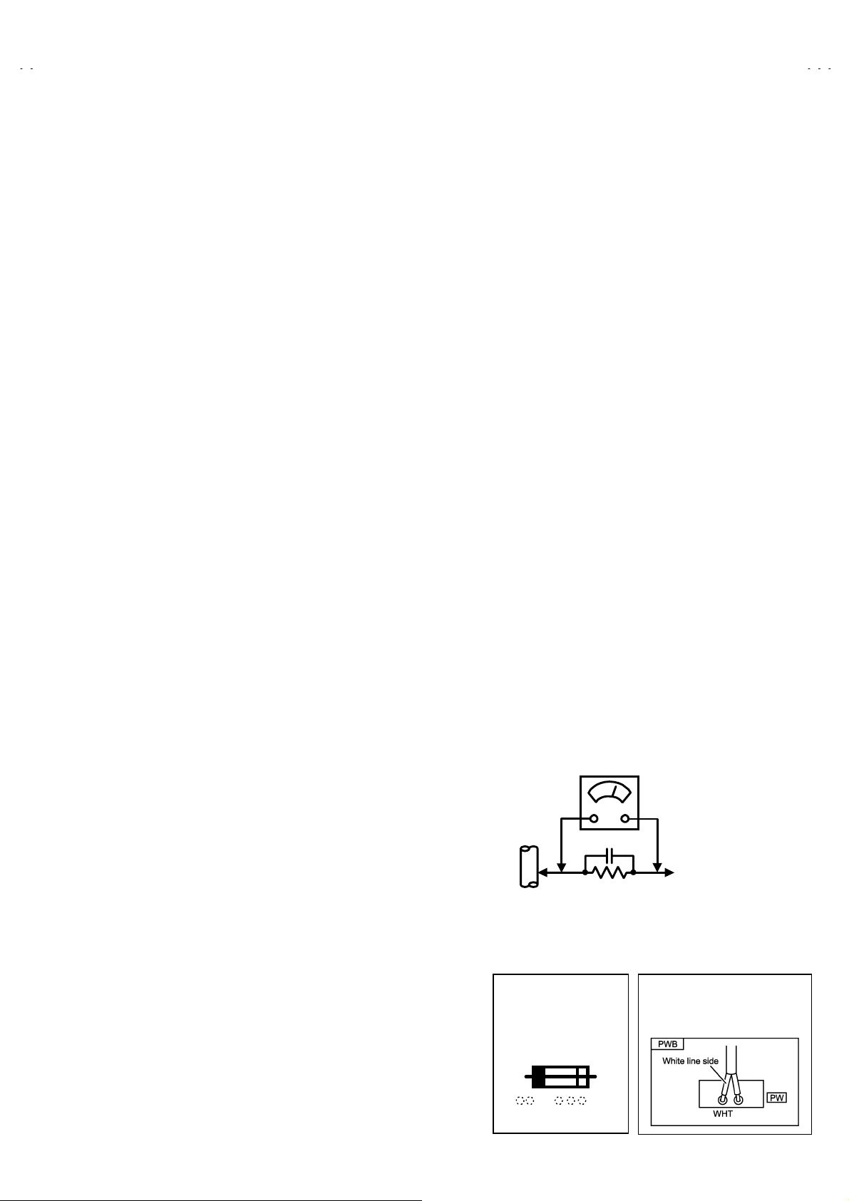
Alternate Check M ethod
zzzz
Plug the AC line cord directly into the AC outlet (do not use a
line isolation transf ormer during this check.). Use an AC
voltmeter having 1000 ohms per volt or more sensitivity in the
following manner. Connect a 1500Ω 10W resistor paralleled
by a 0.15μF AC-type capacitor between an exposed metal
part and a known good earth ground (water pipe, etc.).
Measure the AC voltage across the resistor with the AC
voltmeter. Move the resistor connection to each exposed metal
part, particularly any exposed metal part having a return path to
the chassis, and measure the AC voltage across the resistor.
Now, reverse the plug in the AC outlet and repeat each
measurement. Any voltage measured must not exc eed 0.75V
AC (r.m.s.). This corresponds to 0.5mA AC (r.m.s.).
However, in tropic al area, this must not exceed 0.3V AC
(r.m.s.). This corresponds to 0.2mA AC (r.m.s.).
AC VOLTMETER
(HAVING 1000
GOOD
EARTH
GROUND
11.
High voltage hold down circuit check.
After repair of the high voltage hold down circuit, this circuit
shall be checked to operate correctly.
See item "
circuit
This mark shows a fast
operating fuse, the
letters indicated below
show the rating.
0.15μF AC-T YPE
1500
10W
Ω
How to check the high voltage hold down
".
OR MORE SENSITIVITY)
PLACE THIS PROBE
ON EACH EXPOSED
METAL PART
POWER CORD
REPLACEMENT W ARNING.
Connecting the white line side of power
cord to “WHT” character side.
/V,
Ω
A V
No. 51963
3
Page 4
C-13310
C-13311
FEATURES
New chassis design enables use of a single board with simplified
z
circuitry.
Provided with miniature tuner (TV/CATV).
z
Multifunctional remote control permits picture adjustment.
z
Adoption of t he CHANNE L GUARD function prevents the
z
specific channels f rom being selected, unless the “ID number” is
key in.
Adoption of the VIDEO STATUS function.
z
z
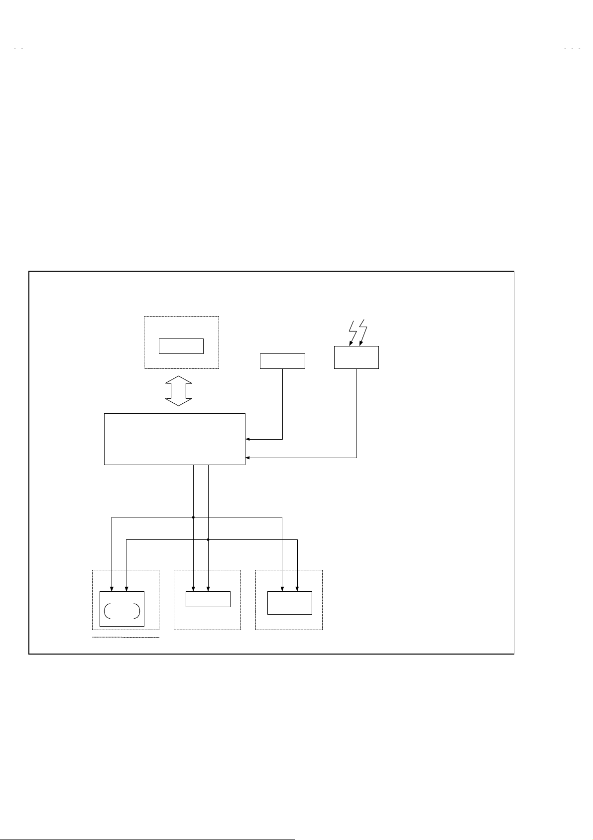
SYSTEM BLOCK DIAGRAM
MEMORY IC
SCL
SDA
Adoption of t he ON/OFF TIMER function.
z
Adoption of the HYPER SCAN function.
z
With 75ΩV/U in c ommon (F-Type) ANT Terminal.
z
SLEEP TIMER for setting in real time.
z
Closed-caption broadc asts c an be viewed.
z
Audio Video input terminal.
z
Built-in V-CHIP system.
z
REMOTE
IF1
CONTROL
TUNER
TUNER
CONTROL
CPU
(MAIN MICON)
SCL SDA
TONE
AFC
1Chip
DECODER
4
No. 51963
Page 5
MAIN DIFFERENCE LIST
Model
Parts Name
MAIN PW B SFV-1079A-M2 SFV-1084A-M2
C-13310
/S
C-13311
C-13310
C-13311
/S
POWER CORD
FRONT CABINET LC10055- 011A-A LC10055- 012A-A
POWER KNOB LC30376- 001A-A LC30376- 002A-A
CONTROL KNOB LC30189-001B-A LC30189-002B-A
REAR COVER LC10056- 001G-A LC10056- 002G-A
POWER CORD CLAMP LC20106-001D-A LC20106-002C-A
REMOTE CONTROL UNIT RM-C205-1C RM-C205W-1C
WHITE MARK
QMPD390-200-JS
(Within MAIN PWB)
×
QMPD209-200-JC
(Within MAIN PWB)
GQ40012-001A-A
No. 51963
5
Page 6

C-13310
C-13311
SPECIFIC SERVICE INSTRUCTIONS
DISASSEMBLY PROCEDURE
REMOVING THE REAR COVER
1. Unplug the power supply cord.
2. Remove the 5 screws marked
3. W ithdraw the REAR COVER toward you.
[CAUTION]
When reinstalling the rear c over, carefully push it inward after
•
inserting the MAIN PW B into the rear c over groove.
REMOVING THE MAIN PW BOARD
1. Slightly raise the both sides of the MAIN PW Board by hand and
withdraw the MAIN PW Board backward.
(If necess ary, take off the wire clamp and connectors, etc.)
as shown in Fig.1.
####
REMOVING THE SPEAKER
• After removing the MAIN PW board.
1. By holding up the SPEAKER HOLDER marked
unlocking the claw, the SPEAKER HOLDER can be removed.
Then you can remove the SPEAKER.
slightly and
$$$$
CHECKING THE MAIN PW BOARD
1. To check the back side of the MAIN PW Board.
1) Pull out the MAIN PWB. (Refer to REMOVING THE MAIN
PWB).
2) Erect the chassis ver tically so that you can easily check the
back side of the MAIN PW Board.
[CAUTION]
When erecting the MAIN PWB, be careful so that there will be no
•
contac ting with other PW Boar d.
Before turning on power, make sure that the CRT earth wire and
•
other connectors are pr operly c onnected.
WIRE CLAMPING AND CABLE TYING
1. Be sure clamp the wire.
2. Never remove the c able tie used for tying the wires together.
Should it be inadvertently removed, be sure to tie the wir es with
a new cable tie.
6
No. 51963
Page 7
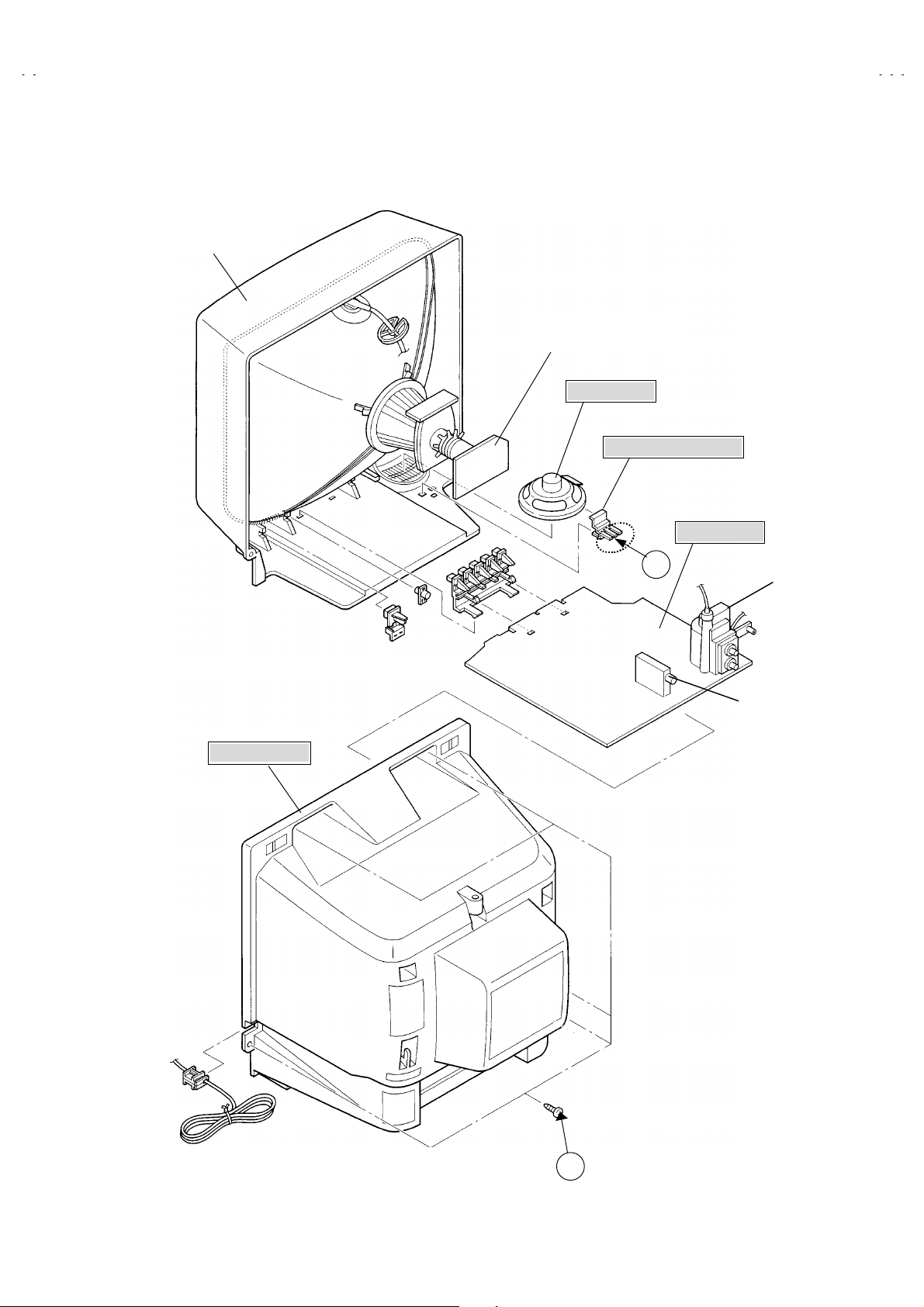
FRONT CABINET
C-13310
C-13311
CRT SOCKET PWB
(Within MAIN PWB)
SPEAKER
SPEAKER HOLDER
MAIN PWB
REAR COVER
B
HVT
TUNER
Fig.1
No. 51963
A
(×5)
7
Page 8
C-13310
C-13311
MEMORY IC REPLACEMENT
1. Memory IC
This model use a memory IC.
This memory IC stores data for pr oper operation of the video and deflection circuits.
When replacing, be sure to use an IC containing this (initial value) data.
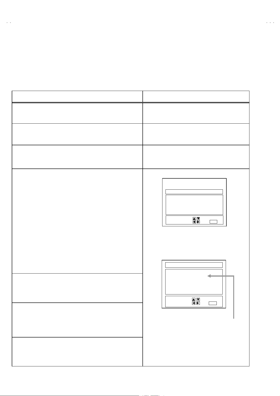
2. Memory IC replacement procedure
Procedure Screen display
(1) Power off
Switch off the power and disconnect the power cord from the outlet.
(2) Replace the memory IC
Initial value must be entered into the new IC.
(3) Power on
Connect the power cord to the outlet and s witch on the power.
(4) System constant check and setting
1) Press
SLEEP TIMER
” is being displayed, press
MIN.
key and, while the indication of “
DISPLAY
key and
VIDE O ST ATUS
SLEEP TIM ER 0
on the remote control unit simultaneously.
2) The SERVICE MENU screen of Fig.1 is displayed.
3) While the SERVICE MENU is displayed, again simultaneously press
the DISPLAY and VIDEO STATUS keys to display the Fig.2 SYSTEM
CONSTANT screen.
4) Refer to the SYSTEM CONSTANT table 1 and check the setting items.
Where these differ, select the setting item with t he MENU UP/DOW N
key and adjust the setting with the MENU LEFT/RIGHT keys. (The
letters of the s elected item are displayed in yellow.)
5) Af ter adjusting, release the MENU LEFT/RIGHT key to store the setting
value.
6) Press the EXIT key twic e to return the normal screen.
(5) Receive channel setting
Refer to the OPERATING INSTRUCTIONS(USER'S GUIDE) and set the
receive c hannels (Channels Preset) as described.
(6) User settings
Check the user setting items according to Table 2.
Where these do not agree, refer to the OPERATING INSTRUCTIONS
(USER'S GUIDE) and set the items as described.
key
SERVICE MENU
PICTURE
GAME
LOW LIGHT HIGH LIGHT
RF AFC CHK
VCO(CW)
SELECT BY EXIT BY
OPERATE BY EXIT
Fig.1
SYSTEM CONSTANT
*******
MODEL :
V-CHIP : YES
CAN V-CHIP : YES
********-*****
********-*****
********-*************-*****
SELECT BY EXIT BY
OPERATE BY EXIT
*******
**************
Fig.2
Indicated M odel No.
(7) SERVICE MENU setting
Verify what to s et in the SERVICE MENU , and s et whatever is
necessary.(Fig.1) Refer to the SERVICE ADJUSTMENT f or setting.
8
No. 51963
Page 9

TABLE 1 (System Constant setting)
Setting item Setting content
C-13310
C-13311
Setting value
C-13310/S C-13311/S
MODEL Display the each application model
V-CHIP YES
CAN V-CHIP YES
YES NO
YES
NO
TABLE 2 (User setting value)
Setting item Setting value
1. Use r emote c ontroller keys
POWER
CHANNEL
CHANNEL PRESET
VOLUME
INPUT (TV/VIDEO)
DISPLAY
SLEEP TIMER
VIDEO STATUS
2. Setting of MENU
TINT
COLOR
PICTURE
BRIGHT
DETAIL
NOISE MUTING
SET VIDEO STATUS
SET CLOCK
ON/OFF TIMER
LANGUAGE
CLOSED CAPTION
BACKGROUND
AUTO TUNER SETUP
CHANNEL SUMMARY
V-CHIP
SET LOCK CODE
OFF
CH 02
See OPERATING INSTRUCTIONS.
10
TV
OFF
0
STANDARD
CENTER
CENTER
CENTER
CENTER
CENTER
OFF
ALL CENTER
Unnecessary to set
OFF
ENG
OFF
BLACK
TUNER MODE : AIR
Unnecessary to set
OFF
Unnecessary to set
C-13310 C-13311
No. 51963
9
Page 10

C-13310
C-13311
REPLACEMENT OF CHIP COMPONENT
CAUTIONS
1. Avoid heating f or more than 3 s econds.
2. Do not rub the electrodes and the resist parts of the pattern.
3. When removing a chip part, melt the solder adequately.
4. Do not reus e a chip part after removing it.
SOLDERING IRON
1. Use a high insulation soldering iron with a thin point ed end of it.
2. A 30w soldering iron is recommended f or easily removing parts.
REPLACEMENT STEPS
How to remove Chip parts
1.
Resistors, capacit ors, etc.
(1) As shown in the figure, pus h the part with tweezers and
alternately melt the solder at each end.
2. How to install Chip parts
Resistors, capacit ors, etc.
(1) Apply solder to the pattern as indicated in the figure.
(2) Shift with tweezers and remove the chip part.
Transistors, diodes, variable resistors, etc.
(1) Apply extra s older to each lead.
SOLDER
(2) As shown in the figure, pus h the part with tweezers and
alternately melt the solder at each lead. Shift and remove
the chip part.
SOLDER
(2) Grasp the chip part with tweezers and place it on the
solder. Then heat and melt the solder at both ends of the
chip part.
Transistors, diodes, variable resistors, etc.
(1) Apply solder to the pattern as indicated in the figure.
(2) Grasp the chip part with tweezers and place it on the
solder.
(3) First solder lead
(4) Then solder leads
as indicated in the figur e.
A
A
B
C
and C.
B
Note : After remov ing the part, remove remaining solder from
the pattern.
10
A
B
C
No. 51963
Page 11

SERVICE ADJUSTMENTS
ADJUSTMENT PREPARATION:
1. You can make the necessary adjustments for this unit with
either the Remote Control Unit or With the adjustment tools
and parts as given below.
2. Adjustment with the Remote Control Unit is made on the
basis of the initial setting values, however, the new setting
values which set the scr een to its optimum condition may
differ from the initial settings.
3. Make sure that AC power is turned on correctly.
4. Turn on the power for set and test equipment before use, and
start the adjustment procedures after waiting at least 30 minutes.
5. Unless otherwise specified, prepare the most suitable reception
or input signal f or adjustment.
ADJUSTMENT EQUIPMENT
1. DC voltmeter (or digital voltmeter)
2. Oscilloscope
3. Signal generator (Pattern generator)[NTSC
4. Remote control unit
5. TV audio multiplex signal generator.
6. Frequency counter
]
6. Never touch any adjustment parts which are not specified in the
list for this adjust ment - var iable resistors, transformers,
condensers, etc.
7. Presetting before adjustment.
Unless otherwise specified in the adjustment instructions, preset
the following functions with the r emote c ontrol unit:
User mode position
MENU ITEM PRESET VALUE
VIDEO STATUS STANDARD
TINT / COLOUR
PICTURE / BRIGHT
DETAIL
C-13310
C-13311
CENTER
ADJUSTMENT ITEMS
Adjustment item Adjustment item Adjustment item
WHITE BALANCE
B1 POW ER SUPPLY
z
VIDEO / DEF. CIRCUIT
z
IF VCO
RF. AGC SUB BR IGHT
FOCUS SUB CONTRAST
V. S IZE SUB COLOR
H. POSITION SUB TINT
z
Low Light / High Light
PICTURE
z
PURITY / CONVERGENCE
z
PURITY
STATIC CONVERGENCE
DYNAMIC CONVERGENCE
No. 51963
11
Page 12

C-13310
C-13311
ADJUSTMENT PARTS LOCATION
MAIN PWB
REMOCON
RECEIVER
FRONT
MENU
TP-91
(B1)
PW
DEG
S756
POWER
R926
F902
F901
ON
TIME R
T161
CW
+
VOL
TP-12B
T131
TUNER
-
IC701
CW
IC201
-
+
CH
IC702
T
U
S
X
HV
HVT
TP-E
( )
IC921
CRT SOCKET PWB
(Within MAIN PWB ASS'Y)
TP-R
T
TP-E
C
UPPER : FOCUS
LOWER : SCREEN
(SOLDER SIDE)
TOP
E1
CRT EARTH
(BRAIDED ASS'Y)
U
12
No. 51963
Page 13

BASIC OPERATION SERVICE MENU
1. TOOL OF SERVICE MENU OPERATION
Operate the SERVICE MENU with the REMOTE CONTROL UNIT.
2. SERVICE MENU ITEMS
In general, basic setting(adjustments) items or verifications are performed in the SERVICE MENU.
PICTURE
z
GAME
z
LOW LIGHT
z
HIGH LIGHT
z
RF AFC CHK
z
VCO (CW )
z
3. Basic Operations of the SERVIC E MENU
(1) How to enter the SERVICE MENU.
Press
STAT US
(2) SERVICE MENU screen selection
Press the UP / DOWN key of the MENU to select any of the following items.
(The letters of the selected items are displayed in yellow.)
・・・・・・・・・・・・・・・・・・・・
・・・・・・・・・・・・・・・・・・・・・・・
・・・・・・・・・・・・・・・・・・
・・・・・・・・・・・・・・・・・
・・・・・・・・・・・・・・・・・
・・・・・・・・・・・・・・・・・・・
SLEEP TIMER
key on the remote control unit simultaneously to enter the
key and, while the indication of “
This sets the setting values (adjustment values) of the VIDEO/CHROMA and DEFLECTION circuits.
This is used when the GAME MODE is adjusted.
This sets the setting values (adjustment values) of the WHITE BALANCE circuit.
This sets the setting values (adjustment values) of the WHITE BALANCE circuit.
This is used when the IF VCO is adjusted.
This is used when the IF VCO is adjusted.
SLEEP TIM ER 0 MIN.
SERVICE MENU
[Do not adjust]
” is being displayed, press
screen ① shown in the next figure page.
DISPLAY
C-13310
C-13311
key and
VIDEO
PICTURE
●
GAME
●
LOW LIGHT
●
RF AFC CHK
●
VCO(CW)
●
(3) Enter the any setting ( adjustment ) mode
PICTURE mode
z
1) If select any of PICTURE item, and the LEFT / RIGHT key is press ed from SERVICE MENU ( MAIN MENU ), the screen ② will be
displayed as shown in figure page later.
2) Then the UP / DOW N key is press ed, the PICTURE mode screen ③ is displayed, and the PICTURE setting c an be performed.
GAME, LOW LIGHT, HIGH LIGHT, RF AFC CHK and VCO (CW) mode
z
1) If select any of GAME / LOW LIGHT / HIGH LIGHT / RF AFC CHK / VCO (CW) items, and the LEFT / RIGHT key is pressed from
SERVICE MENU ( MAIN MENU ), the screens ④ ⑤ ⑥ ⑦ ⑧ will be displayed as shown in figure page later.
2) Then the settings or verifications can be performed.
HIGH LIGHT
●
No. 51963
13
Page 14

C-13310
C-13311
SERVICE MENU (MAIN MENU)
①①①①
SERVICE MENU
PICTURE
GAME
LOW LIGHT HIGH LIGHT
RF AFC CHK
VCO(CW)
SELECT BY
OPERATE BY
HIGH LIGHT MODE
⑥⑥⑥⑥
HIGH LIGHT
***
***
******
RF AFC CHK MODE [DO NOT ADJUST]
⑦⑦⑦⑦
EXIT BY
EXIT BY
EXIT
***
***
******
EXIT
SCREEN
②②②②
IT
IT
SELECT BY
EXIT BY
EXIT
IT
SELECT BY
OPERATE BY
1. BRIGHT
STATUS
PICTURE MODE
③③③③
***
***
******
********
********
****************
EXIT BY
EXIT
IT
RF AFC
FINE
STATUS
SELECT BY
OPERATE BY
⑧⑧⑧⑧
TOO HIGH
ABOVE REFERENCE
BELOW REFERENCE
TOO LOW
SYNC : YES
********
********
****************
VCO (CW) MODE
ON
***
***
******
EXIT BY
EXIT
EXIT BY
EXIT
IT
GAME MODE
④④④④
TINT
COLOR
PICTURE
BRIGHT
DETAIL
IT
SELECT BY
OPERATE BY
BRIGHT
BRIGHT
***
***
******
***
***
******
***
***
******
***
***
******
***
***
******
LOW LIGHT MODE
⑤⑤⑤⑤
*** *** ***
*** *** ***
*** *** ****** *** ***
***
***
******
EXIT BY
EXIT
EXIT BY
EXIT
IT
IT
14
No. 51963
Page 15

(4) Setting method
1) UP / DOWN key of the MENU
Select the SETTING ITEM.
2) LEFT / R IGHT key of the MENU
Setting( adjust) the INITIAL SETTING VALUE of the SETT ING
ITEM.
When the key is released the SETTING VA LUE will be stored
(memorized).
3) EXIT key
Returns to the pr evious screen.
(5) Releasing SERVICE MENU
1) After returning to the SERVICE MENU upon completion of the
setting (adjustment) work, press the EXIT key again.
★
1. BRIGHT
STATUS
SELECT BY
OPERATE BY
PICTURE MODE
SETTING
ITE M
***
TINT
COLOR
PICTURE
BRIGHT
DETAIL
***
******
***
***
******
***
***
******
***
***
******
***
***
******
***
***
******
********
********
****************
EXIT BY
EXIT
C-13310
C-13311
I
T
INIT IAL
SETTING VALUE
↓ (Adjust)
SETTING VALUE
★
SELECT BY
OPERATE BY
GAME MODE
The letter of the selected
Items are displayed in yellow.
EXIT BY
EXIT
IT
No. 51963
15
Page 16

C-13310
C-13311
INITIAL SETTING VALUE OF SERVICE MENU
1. Adjustment of the SERVICE MENU is made on the basis of the initial setting values; however, the new setting values which set the screen
in its optimum c ondition may differ from the initial setting.
2. Do not change the initial setting values of t he setting (Adjustment) items not listed in “ADJUSTMENT”.
PICTURE MODE
zzzz
The four setting items in the video mode No.7 EXT BRI., No.8 E XT PIC., No.11 EXT TINT and No.12 EXT COL. are linked to the items in
the TV MODE No.1 BRIGHT, No.2 PICTURE, No.5 TINT and No.6 COLOR, respectively. W hen the setting items in the TV mode are
adjusted, the values in the setting items in the video mode are revised automatically to the same values in the TV mode.(The initial setting
values given in ( ) are off-set values.)
When the four items (No.7, 8, 11 and 12) are adjusted in the video mode, the setting values in each item are revis ed independently.
No. Setting ( Adjustment) items Variable range Initial setting value
1. BRIGHT
2. PICTURE
3. TV DTL(TV DETAIL)
4. TV BPF(TV B.P.FILTER) 0 / 1 0
5. TINT
6. COLOR
7. EXT BRI.(EXT.BRIGHT)
8. EXT PIC.(EXT.PICTURE)
9. EXT DTL(EXT.DETAIL)
10. EXT BPF(EXT.B.P.FILTER) 0 / 1 0
11. EXT TINT
12. EXT COL.(E XT.COLOR)
13. V SIZE
14. V CENT.(V.CENTER)
15. H POS.(H.POSITION)
16. OSD HP (OSD H POSITION)
17. OSD VP (OSD V POSITION)
18. H AFC 0 / 1 0
19. RF AGC
20. OSC SEL 0 / 1 0
0 ~ 127
0 ~ 127
0 ~ 63
0 ~ 127
0 ~ 127
25
±
25
±
0 ~ 63
25
±
25
±
0 ~ 63
0 ~ 7
0 ~ 31
0 ~ 31
0 ~ 15
0 ~ 63
(-2)
(-2)
(+9)
(+3)
64
60
23
57
55
25
20
0
20
23
14
40
16
No. 51963
Page 17

GAME MODE
z
No. Setting (Adjustment) item Variable range initial setting value
C-13310
C-13311
1.
2.
3.
4.
5.
LOW LIGHT MODE
z
No.
1.
2.
3.
HIGH LIGHT MODE
z
No.
1.
2.
TINT
COLOR
PICTURE
BRIGHT
DETAIL
Setting (Adjustment) item
R CUTOFF
G CUTOFF 0 ~ 255 20
B CUTOFF
Setting (Adjustment) item
G DRIVE 0 ~ 255 128
B DRIVE
20
±
20
±
20
±
20 -2
±
15
±
Variable range initial setting value
0 ~ 255
0 ~ 255
Variable range initial setting value
0 ~ 255
±
±
-10
+10
20
20
128
0
0
RF AFC CHK MODE
z
No.
1.
2.
Setting (Adjustment) item
Variable range initial setting value
RF AFC ON / OFF
FINE
-77 ~ +77
ON
±***
DO NOT
ADJUST
No. 51963
17
Page 18

C-13310
C-13311
ADJUSTMENTS
B1 POWER SUPPLY
z
Item
Check of
B1 POWER
SUPPLY
ADJUSTMENT OF VIDEO / DEF. CIRCUIT
z
Item
IF VCO
adjustment
Measurin g
instrument
DC Voltmeter
Measurin g
instrument
Signal
generator
TOO HIGH
ABOVE REFERENCE
BELOW REFERENCE
TOO LOW
SYNC : YES
Test point Adjustment part Description
TP-91 (B1)
TP-E(
)
Test point Adjustment part Description
EXIT BY
EXIT
CW TRANSF. (T131)
[VCO(CW)] MODE
YELLOW
IT
1. Receive a black-and-white signal.
2. Connect the DC Voltmeter to TP-91 (B1) and TP-E(
3. Confir m that t he voltage is DC134V
Under normal conditions, no adjustment is required.
z
1. Receive a NTSC broadcast. (us e channels without offset
frequenc y).
2. Select the VCO(CW) mode from the SERVICE MENU.
3. Confirm the color change (yellow) from “TOO HIGH” to
TOO LOW”by CW TRANSF. and “SYNC : YES” being
“
shown on the screen. Then, adjust CW TRANSF. until
BELOW REFERENCE” mark turns yellow and confirm
“
again “ SYNC : YES” being shown on the screen.
+2V
-2.5V.
).
RF. AGC
adjustment
FOCUS
adjustment
Signal
generator
No.19 RF AGC
FOCUS VR
[In HVT]
1. Receive a broadcast.
2. Select “No.19 RF AGC” of the PICTURE MODE.
3. Press the MUTE key and turn off color.
4. With the MENU LEFT key, get noise in the screen picture. (0
side of setting value)
5. Press the MENU RIGHT key and stop when nois e disappears
from the screen.
6. Change to other channels and make sure that there Is no
irregularity.
7. Press the MUT E key and get c olor out.
1. Receive a cross hatch signal.
2. While looking at the screen, adjust FOCUS VR so that the
vertical and horizontal lines will be clear and in fine detail.
3. Make sure that the picture is in focus even when the screen
gets darkened.
18
No. 51963
Page 19

C-13310
C-13311
Item
V.SIZE
Adju stment
Screen
size
92%
H.POSITION
Adju stment
Measurin g
instruments
Signal
generator
Picture size 100%
Signal
generator
Test point Adjustment part Description
No.13 V.SIZE
Screen size
Picture
size
100%
No.15 H POS.
1. Receive a crosshatch signal.
2. Select No.13 V SIZE in the PICTURE MODE.
3. Set the initial setting value of No.13 V SIZE with the LEFT /
RIGHT key of the MENU.
4. Adjust No.13 V SIZE until the vertic al screen size is 92%.
1. Receive a crosshatch signal.
2. Select the No.15 H POS. of the PICTURE MODE.
3. Set the initial setting value of the N o.15 H POS. with the LEFT /
RIGHT key of the MENU.
4. Adjust the No.15 H POS. until the screen will be horizontally
centered.
No. 51963
19
Page 20

C-13310
C-13311
ADJUSTMENT OF WHITE BALANCE
z
Item
WHITE
BALANCE
(Low Light)
Adju stment
Measurin g
instruments
Signal
generator
R CUTOFF
BRIGHT
***
***
******
BRIGHT
[LOW LIGHT] MODE
Test point Adjustment part Description
BRIGHT
G CUTOFF
***
***
******
***
***
******
BRIGHT
R. CUTOFF
G. CUTOFF
B. CUTOFF
SCREEN VR
[In HVT]
B CUTOFF
***
***
******
EXIT BY
IT
EXIT
1. Receive a black-and-white signal.(Color off)
2. Select the【LOW LIGHT】MODE from the SERVICE MENU.
3. Set the initial setting value of BRIGHT with the LEFT /
RIGHT key of the remote control unit.
4. Set the initial setting value of R CUTOFF, G CUTOFF and
B CUTOFF with the ④ to ⑨ key of the remote control
unit.
5. Display a single horizontal line by pressing the ①key of the
remote c ontrol unit.
6. Turn the screen VR all the way to the left.
7. Turn the screen VR gradually to the right from the left until
either one of the red, blue or green colors appears faint ly.
8. Adjust the two colors which did not appear until the single
horizontal line that is displayed becomes white using the
④
to ⑨ keys of the remote control unit.
9. Turn the screen VR to where the single horizontal line
glows faintly.
10. Press the ② key to return to t he regular screen.
WHITE
BALANCE
(High Light)
Adju stment
REMOTE CONTROL UNIT
H.LINE ON EXITH.LINE OFF
1 2 3
R CUTOFF B CUTOFFG CUTOFF
R CUTOFF B CUTOFFG CUTOFF
Signal
generator
[HIGH LIGHT] MODE
G DRIVE
HIGH LIGHT
***
*** ***
******
The ③ EXIT key is the cancel key for the WHITE
*
BALANCE.
54
6
987
G. DRIVE
B. DRIVE
1. Receive a black-and-white signal. (Color off)
2. Select the【HIGH LIGHT】MODE in the SERVICE MENU.
3. Set the initial setting value of G DRIVE and B DRIVE with
the ⑤, ⑥, ⑧ and ⑨ keys of the remote control unit.
4. Adjust the screen until it becomes white using the ⑤, ⑥,
and ⑨ keys of the remote control unit.
⑧
The ③ (EXIT) key is the cancel key for the W HITE
B DRIVE
*
BALANCE.
Remote Control Unit
***
******
EXIT BY
EXIT
IT
key : H.LINE ON
①
key : H.LINE OFF
②
key : EXIT
③
key : G DRIVE
⑤
key : B DRIVE
⑥
key : G DRIVE
⑧
key : B DRIVE
⑨
▲
▲
▼
▼
20
No. 51963
Page 21

ADJUSTMENT OF PICTURE
z
Item
SUB
BRIGHT
Adju stment
Measurin g
instruments
Test point Adjustment part Description
No.1 BRIGHT
1. Receive a broadcast.
2. Select No.1 BRIGHT of the PICTURE MODE.
3. Set the initial setting value of the No.1 BRIGHT with the
LEFT / RIGHT key of the MENU.
4. If the brightness is not best with the initial setting value,
make fine adjustment of the No.1 BRIGHT until you get the
optimum brightness.
C-13310
C-13311
SUB
CONTRAST
Adju stment
SUB
COLOR
Adju stment
SUB TINT
Adju stment
No.2 PICTURE
No.6 COLOR
No.5 TINT
1. Receive a broadcast.
2. Select No.2 PICTURE of the PICTURE MODE.
3. Set the initial setting value of the No.2 PICTURE with the
LEFT / RIGHT key of the MENU.
4. If the contrast is not best with the initial s etting value, make
fine adjustment of the No.2 PICTURE until you get the
optimum contrast.
1. Receive a broadcast.
2. Select No.6 COLOR of the PICTURE MODE.
3. Set the initial setting value of the No.6 COLOR with the
LEFT / RIGHT key of the MENU.
4. If the color is not best with the initial setting value, make fine
adjustment of the No.6 COLOR until you get the optimum
color.
1. Receive a broadcast.
2. Select No.5 TINT of the PICTURE MODE.
3. Set the initial setting value of the No.5 TINT with the LEFT /
RIGHT key of the MENU.
4. If the tint is not best with the initial setting value, make fine
adjustment of the No.5 TINT until you get the optimum tint.
No. 51963
21
Page 22

C-13310
C-13311
ADJUSTMENT OF PURITY / CONVERGENCE
PURITY ADJUSTMENT
1. Demagnetize CRT with the demagnetizer.
2. Loosen the retainer screw of the deflection yoke.
3. Remove the wedges.
4. Input a green raster signal from the signal generator, and turn
the screen to gr een raster.
5. Move the deflection yoke backward.
6. Bring the long lug of the purity magnets on the short lug and
position them horizontally. (Fig.2)
7. Adjust the gap between two lugs so that the GREEN RASTER
will come into the center of the screen. (Fig.3)
8. Move the deflection yoke forward, and fix the position of the
deflection yoke s o that the whole screen will become green.
9. Ins ert the wedge to the top side of the deflection yoke so that it
will not move.
WEDGE
CRT
P/C MAGNETS
y
P : PURITY MAGNET
4 : 4 POLES
6 : 6 POLES
(convergence magnets)
(convergence magnets)
Fig.1
PURITY MAGNETS
DEFLECTION
YOKE
P
46
P / C
MAGNETS
10. Input a crosshatch signal.
11. Verify that the screen is horizontal.
12. Input red and blue raster signals, and make sure that purity is
properly adjusted.
Long lug
Short lug
(FRONT VIEW )
Bring the long lug over the short lug
and position them horizontally.
Fig.2
GREEN RASTER
CENTER
Fig.3
22
No. 51963
Page 23

STATIC CONVERGENCE ADJUSTMENT
1. Input a crosshatch signal.
2. Using 4-pole convergence magnets, over lap the red and blue
lines in the center of the screen (Fig.1) and turn them to
magenta (red/blue).
3. Using 6-pole convergenc e magnets, overlap the
magenta(red/blue) and green lines in the center of the screen
and turn them to white.
4. Repeat 2 and 3 above, and make best convergenc e.
DYNAMIC CONVERGENCE ADJUSTMENT
1. Move the deflection yok e up and down and overlap the lines in
the periphery. (Fig. 2)
2. Move the deflection yok e left to right and overlap the lines in the
periphery. (Fig. 3)
3. Repeat 1 and 2 above, and make best convergenc e.
(FRONT VIEW )
(FRONT VIEW )
BLUE
GREEN
RED
RED
Fig.1
GREEN
C-13310
C-13311
BLUE
RED
GREEN
BLUE
After adjust ment, fix the wedge at the original position.
●
Fasten the retainer screw of the deflection yoke.
Fix the 6 magnets with glue.
(FRONT VIEW )
GREEN
RED
BLUE
BLUE
GREEN RED
Fig.2
BLUE
Fig.3
GREEN
RED
RED
GREEN
BLUE
BLUE
GREEN
RED
No. 51963
23
Page 24

C-13310
C-13311
HOW TO CHECK THE HIGH VOLTAGE HOLD DOWN CIRCUIT
1. HIGH VOLTAGE HOLD DOWN CIRCUIT
After repairing the high voltage hold down circuit shown in Fig. 1.
This circuit shall be checked to operate correctly.
2. CHECKING OF THE HIGH VOLTAGE HOLD DOWN CIRCUIT
(1) Turn the POWER SW ON.
(2) As shown in Fig. 1, set the resistor (between X connector 1 & 3 ).
(3) Make sure that the screen picture dis appears.
(4) Temporarily unplug the power cord.
(5) Remove the resistor (between X connector 1 & 3 ).
(6) Again plug the power c ord, make sure that the normal picture is displayed on the scr een.
POWER
ON OFF
D958
D563
12V
R953
Q561
R564
Q951
RY901
Q562
12V
C562
D562
RESISTOR
14.46k
Ω±
Ω±
Ω±Ω±
3 2 1
R562
R563
Fig. 1
1%1/4W
C561
CONNECTOR
X
D561
HEATER
HVT
4
R561
24
No. 51963
Page 25

SELF CHECK FUNCTIONS
1. Outline
This model has self check functions given below. W hen a malfunction has been detected, the POWER is turned off and the LED flashes to
inform of the failure . The malfunction is detected by the signal input state of the control line connected to the microcomputer.
2. Self check items
Check item Details of detection Method of detection State of malfunction
C-13310
C-13311
CRT NECK protector
Also detected if the
power supply line output
from the HVT (High
voltage Transf ormer) has
shorted with the ground.
3. Self check indicating function
The self-check function begins detection about 5 seconds after
power is supplied.
In the event a malfunction is detected, the power is cut off
immediately.
At this time, the ON-TIMER LED flashes to inform of the
malfunction.
[ON-TIMER LED indication]
The ON-T IMER LED flashes at 0.5 s econds intervals.
When th e vertical circuit Scorrection capacitor C 427
is shorted, detect the
potential drop of the C427,
and prevent the burn
damage to the CRT NECK.
(Grounding of shorting of
the power supply output
from the HVT to the vertic al
circuit, and the small signal
power supply is also
detected.)
The microcomputer detects at
1 second intervals.
If NG is detected for more than
1 ms, a malfunction is interpreted.
POWER
Supplied
Aft er about
5 seconds
Start of
detection
When a malfunction has been
detected, the POW ER is turned
off. While the POWER is being
turned off , the power key of the
remote controller is not operational
until the power code is taken out
and put in again.
Malfunction
is detected
POWER OFF
Flashing
ON-TIMER LED
No. 51963
25
Page 26

C-13310
C-13311
26
No. 51963
 Loading...