

Page 1

SERVICE MANUAL
COLOR TELEVISION
C-13210
C-13211
BASIC CHASSIS
C-13210
C-13211
/S
/S
FV4
CONTENTS
!
SPECIFICATIONS
!
SAFETY PRECAUTIONS
!
FEATURES
!
MAIN DIFFERENCE LIST
!
SPECIFIC SERVICE INSTRUCTIONS
!
SERVICE ADJUSTM ENTS
!
PARTS LIST
★
OPERATING INSTRUCTIONS
★
STANDARD CIRCUIT DIAGRAM
1
・・・・・・・・・・・・・・・・・・・・・・・・・・・・・・・・
・・・・・・・・・・・・・・・・・・・・・・・・・・・・・・・・ ・・・・・・・・・・・・・・・・・・・・・・・・・・・・・・・・
・・・・・・・・・・・・・・・・・・・・・・・・・・・・・・・・・・・・・・・・・・・・・・・・・・・・・・・・・・・・・・・・
・・・・・・・・・・・・・・・・・・・・・・・・・・・・・・・・
・・・・・・・・・・・・・・・・・・・・・・・・・・・・・・・・ ・・・・・・・・・・・・・・・・・・・・・・・・・・・・・・・・
・・・・・・・・・・・・・・・・・・・・・・・・・・・・・・・・・・・・・・・・・・・・・・・・・・・・・・・・・・・・・・・・
・・・・・・・・・・・・・・・・・・・・・・・・・・・・・・・・
・・・・・・・・・・・・・・・・・・・・・・・・・・・・・・・・ ・・・・・・・・・・・・・・・・・・・・・・・・・・・
・・・・・・・・・・・・・・・・・・・・・・・・・・・・・・・・・・・・・・・・・・・・・・・・・・・・・・・・・・・・・・・・
・・・・・・・・・・・・・・・・・・・・・・・・・・・・・・・・
・・・・・・・・・・・・・・・・・・・・・・・・・・・・・・・・ ・・・・・・・・・・・・・・・・・・・・・・・・・・・
・・・・・・・・・・・・・・・・・・・・・・・・・・・・・・・・・・・・・・・・・・・・・・・・・・・・・・・・・・・・・・・・
・・・・・・・・・・・・・・・・・・・・・・・・・・・・・・・・
・・・・・・・・・・・・・・・・・・・・・・・・・・・・・・・・ ・・・・・・・・・・・・・・・・・・・・・・・・
・・・・・・・・・・・・・・・・・・・・・・・・・・・・・・・・・・・・・・・・・・・・・・・・・・・・・・・・・・・・・・・・
・・・・・・・・・・・・・・・・・・・・・・・・・・・・・・・・
・・・・・・・・・・・・・・・・・・・・・・・・・・・・・・・・ ・・・・・・・・・・・・・・・・・・・・・・・・・・・・・・・・
・・・・・・・・・・・・・・・・・・・・・・・・・・・・・・・・・・・・・・・・・・・・・・・・・・・・・・・・・・・・・・・・
COPYRIGHT © 2001 VICTOR COMPANY OF JAPAN, LTD.
・・・・・・・・・・・・・・・・・・・・・・・・・・・・・・・・ ・・・・
・・・・・・・・・・・・・・・・・・・・・・・・・・・・・・・・・・・・・・・・・・・・・・・・・・・・・・・・・・・・・・・・
・・・・・・・・・・・・・・・・・・・・・・・・・・・
・・・・・・・・・・・・・・・・・・・・・・・・・・・・・・・・・・・・・・・・・・・・・・・・・・・・・・
・・・・・・・・・・・・・・・・・・・・・・・・・・・・・・・・ ・・・・・・・
・・・・・・・・・・・・・・・・・・・・・・・・・・・・・・・・・・・・・・・・・・・・・・・・・・・・・・・・・・・・・・・・
・・・・・・・・・・・・・・・・・・・・・・・・・・・
・・・・・・・・・・・・・・・・・・・・・・・・・・・・・・・・・・・・・・・・・・・・・・・・・・・・・・
・・・・・・・・・・・・・・・・・・・・・・・・・・・・・・・・
・・・・・・・・・・・・・・・・・・・・・・・・・・・・・・・・ ・・・・・・・・・・・・・・・・・
・・・・・・・・・・・・・・・・・・・・・・・・・・・・・・・・・・・・・・・・・・・・・・・・・・・・・・・・・・・・・・・・
・・・・・・・・・・・・・・・・・・・・・・・・
・・・・・・・・・・・・・・・・・・・・・・・・・・・・・・・・・・・・・・・・・・・・・・・・
・・・・・・・・・・・・・・・・・・・・・・・・・・・・・・・・ ・・・・
・・・・・・・・・・・・・・・・・・・・・・・・・・・・・・・・・・・・・・・・・・・・・・・・・・・・・・・・・・・・・・・・
・・・・・・・・・・・・・・・・・・・・・・・・・・・・・・・・
・・・・・・・・・・・・・・・・・・・・・・・・・・・・・・・・ ・・・・・・・・・・・・・・・・・・
・・・・・・・・・・・・・・・・・・・・・・・・・・・・・・・・・・・・・・・・・・・・・・・・・・・・・・・・・・・・・・・・
・・・・・・・・・・・・・・・・・
・・・・・・・・・・・・・・・・・・・・・・・・・・・・・・・・・・
・・・・・・・・・・・・・・・・・・
・・・・・・・・・・・・・・・・・・・・・・・・・・・・・・・・・・・・
・・・・・・・
・・・・・・・・・・・・・・
・・・・
・・・・・・・・
2
3
4
4
5
10
25
2-1
No.51783
Jan. 2001
Jan. 2001
Page 2

C-13210
C-13211
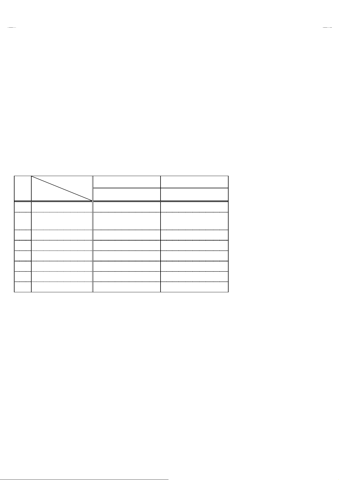
SPECIFICATIONS
Items Content
Dimensions (W
Mass
TV System and Color system
TV Receiving Channels and Frequency
CATV Receiving Channels and Frequency
TV/CATV Total Channel
Intermediate Frequency
Color Sub Carrier
××××H××××
D)
TV RF System
Sound System
VL Band
VH Band
UHF Band
Low Band
High Band
Mid Band
Super Band
Hyper Band
Ultra Band
Sub Mid Band
Video IF Carrier
Sound IF Carrier
14-3/8”×13-1/8”×14-3/4” / 36.4cm×33.4cm×37.4cm
19.8 Ibs / 9.0 kg
CCIR(M)
NTSC
(02~06) 54MHz~88MHz
(07~13) 174MHz~216MHz
(14~69) 470MHz~806MHz
(02~06, A-8) by (02~06&01)
(07~13) by (07~13)
(A~1) by (14~22)
(J~W) by (23~36)
(W+1~W+28) by (37~64)
(W+29~W+84) by (65~125)
(A8, A4~A1) by (01, 96~99)
180 Channels
45.75MHz
41.25MHz (4.5MHz)
3.58MHz
(54MHz~804MHz)
Antenna Input Impedance
Power Input
Power Consumption
Picture Tube
High Voltage
Speaker
Audio Power Output
Video Input
Audio Input
Earphone Jack
Remote Control Unit
75Ω(VHF/UHF) Terminal, F-Type Connector
120V AC, 60Hz
60W (US) / 1.1A (CA)
13” (34cm) Measured Diagonally
22.5kV±1kV (at zero beam current)
3-1/16” (8cm) Round type
1W
1Vp-p, 75
500mVrms ( -4dBs ), High Impedance
3.5mm mono mini jack
RM-C205-1C [C-13210]
RM-C205W-1C [C-13211]
(AA / R6 / UM-3 dry battery×2)
Ω
Design & specifications are subject to change without notice.
2
No. 51783
Page 3

SAFETY PRECAUTIONS
1. The design of this product contains special hardware, many
circuits and components specially for safety purposes. For
continued protection, no changes should be made to the
original design unless authorized in writing by the manufacturer.
Replacement parts must be identical to those used in the
original circuits. Service should be performed by qualified
personnel only.
2. Alterations of the design or circuitry of the products should not
be made. Any design alterations or additions will void the
manufacturer's warranty and will further relieve the
manufacturer of responsibility for personal injury or property
damage resulting therefrom.
3. Many electrical and mechanical parts in the products have
special safety-related characteristi cs. These charact eris t ics are
often not evident from visual inspection nor c an the protection
afforded by them necessarily be obtained by using
replacement components rated for higher voltage, wattage, etc.
Replacement parts which have these special safety
characteristics are identified in the parts list of Service manual.
Electrical components having such features are identified
by shading on the schematics and by (
in Service manual.
does not have the same safety characteristics as the
recommended replacement part shown in the parts list of
Service manual may cause shock, fire, or other hazards.
4.
Use isolation transformer when hot chassis.
The chassis and any sub-chassis contained in some products
are connected to one side of the AC power line. An isolation
transformer of adequate capacity should be inserted between
the product and the AC power supply point while performing
any service on some products when the HOT chassis is
exposed.
5.
Don't short between the LIVE side ground and ISOLATED
(NEUTRAL) side ground or EARTH side ground when
repairing.
Some model's power circuit is partly diff erent in the GND. The
difference of the GND is shown by the LIVE : (") side GND,
the ISOLATED(NEUTRAL) : (#) side GND and EARTH : ($)
side GND. Don't short between the LIVE side GND and
ISOLATED(NEUTRAL) side GND or EARTH side GND and
never measure with a measuring apparatus (oscilloscope etc.)
the LIVE side GND and ISOLATED(NEUTRAL) side GND or
EARTH side GND at the same time.
If above note will not be kept, a fuse or any parts will be broken.
6. If any repair has been made to the chassis, it is recommended
that the B1 setting should be checked or adjusted (See
ADJUSTMENT OF B1 POWER SUPPLY).
7. The high voltage applied to the picture tube must conform with
that specified in Service manual. Excessive high voltage can
cause an increase in X-Ray emission, arcing and possible
component damage, therefore operation under excessive high
voltage conditions should be kept to a minimum, or should be
prevented. If severe arcing occurs, remove the AC power
immediately and determine the cause by visual inspection
(incorrect installation, cracked or melted high voltage harness,
poor soldering, etc.). To maintain the proper minimum level of
soft X-Ray emission, components in the high voltage circuitry
including the picture tube must be the exact replacements or
alternatives approved by the manufacturer of the complete
product.
8. Do not check high voltage by drawing an arc. Use a high
voltage meter or a high voltage probe with a VTVM. Discharge
the picture tube before attempting meter connection, by
connecting a clip lead to the ground frame and connecting the
other end of the lead through a 10kΩ 2W resistor to the anode
button.
9. When service is required, observe the original lead dress.
Extra precaution should be given to assure correct lead dress
in the high voltage circuit area. Where a short circuit has
occurred, those components that indicate evidence of
overheating should be replaced. Always use the
manufacturer's replacement components.
The use of a substitute replacement which
!!!!
) on the parts list
C-13210
C-13211
10.
Isolation Check
(Safety for Electrical Shock Hazard)
After re-assembling the product, always perform an isolation
check on the exposed metal parts of the cabinet (antenna
terminals, video/audio input and output terminals, Control
knobs, metal cabinet, screwheads, earphone jack, control
shafts, etc.) to be sure the product is safe to operate without
danger of electrical shock.
(1)
Dielectric Strength Test
The isolation between the AC primary circuit and all metal parts
exposed to the user, particularly any exposed metal part having
a return path to the chassis should withstand a voltage of
1100V AC (r.m.s.) for a period of one second.
(. . . . Withstand a voltage of 1100V AC (r.m.s.) to an appliance
rated up to 120V, and 3000V AC (r.m.s.) to an appliance rated
200V or more, for a period of one second.)
This method of test requires a test equipment not generally
found in the service trade.
(2)
Leakage Current Check
Plug the AC line cord directly into the AC outlet (do not use a
line isolation transformer during this check.). Using a " Leakage
Current Tester", measure the leakage current from each
exposed metal part of the cabinet, particularly any exposed
metal part having a return path to the chassis, to a known good
earth ground (water pipe, etc.). Any leakage c urrent must not
exceed 0.5mA AC (r.m.s.).
However, in tropical area, this must not exceed 0.2mA AC
(r.m.s.).
""""
Alternate Check Method
Plug the AC line cord directly into the AC outlet (do not use a
line isolation transformer during this check.). Use an AC
voltmeter having 1000 ohms per volt or more sensitivi ty in the
following manner. Connect a 1500Ω 10W resistor paralleled
by a 0.15μF AC-type capacitor between an exposed metal
part and a known good earth ground (water pipe, etc.).
Measure the AC voltage across the resistor with the AC
voltmeter. Move the resistor connection t o each exposed metal
part, particularly any exposed metal part having a return path to
the chassis, and measure the AC voltage across the res istor.
Now, reverse the plug in the AC outlet and repeat each
measurement. Any voltage measured must not exceed 0.75V
AC (r.m.s.). This corresponds to 0.5mA AC (r.m.s.).
However, in tropical area, this must not exceed 0.3V AC
(r.m.s.). This corresponds to 0.2mA AC (r.m.s.).
AC VOLTMETER
(HAVING 1000
GOOD
EARTH
GROUND
11.
High voltage hold down circuit check.
After repair of the high voltage hold down circuit, this circuit
shall be checked to operate correctly.
See item "
circuit
This mark shows a fast
operating fuse, the
letters indicated below
show the rating.
0.15μF AC-TYPE
Ω
10W
1500
How to check the high voltage hold down
".
OR MORE SENSITIVITY)
PLACE THIS PROBE
ON EACH EXPOSED
METAL PART
POWER CORD
REPLACEMENT WARNING.
Connecting the white line side of power
cord to “WHT” character side.
Ω
/V,
A V
No. 51783
3
Page 4
C-13210
C-13211
FEATURES
"
New chassis design enables use of a single board with simplified
circuitry.
"
P rovided with m i ni ature tuner (TV/CATV).
"
Mult i functional remote control permits picture adjustment.
"
Adoption of the CHANNEL GUARD function prevents the
specific channels from being selected, unless the “ID number” is
key in.
"
Adoption of the VIDEO STATUS function.
"
"
"
"
"
"
MAIN DIFFERENCE LIST
Model
!!!!
Parts Name
MAIN PWB SFV-1060A-M2 SFV-1061A-M2
!
POWER CORD QMPD200-200-JC
!
FRONT CABINET LC10055-005A-A LC10055-006A-A
Charcoal model White model
C-13210
(Within MAIN PWB)
/S
QMPD209-200-JC
(Within MAIN PWB)
Adoption of the ON/OFF TIMER function.
With 75ΩV/U in common (F-Type) ANT Terminal.
SLEEP TIMER for setting in real time.
Closed-caption broadcasts can be viewed.
Audio Video input terminal.
Built-in V-CHIP system.
C-13211
/S
POWER KNOB LC30376-001A-A LC30376-002A-A
CONTROL KNOB LC30189-001B-A LC30189-002B-A
!
REAR COVER LC10056-001G-A LC10056-002G-A
!
POWER CORD CLAMP LC20106-001D-A LC20106-002C-A
REMOCON UNIT RM-C205-1C RM-C205W-1C
4
No. 51783
Page 5

SPECIFIC SERVICE INSTRUCTIONS
REPLACEMENT OF CHIP COMPONENT
!
CAUTIONS
1. Avoid heating for more than 3 seconds.
2. Do not rub the electrodes and the resist parts of the pattern.
3. When removing a chip part, melt the solder adequately.
4. Do not reuse a chip part after removing it.
!
SOLDERING IRON
1. Use a high insulation soldering iron with a thin pointed end of it.
2. A 30w soldering iron is recommended for easily removing parts.
!
REPLACEMENT STEPS
How to remove Chip parts
1.
#
Resistors, capacitors, etc.
(1) As shown in the figure, push the part with tweezers and
alternately melt the solder at each end.
2. How to install Chip parts
#
Resistors, capacitors, etc.
(1) Apply solder to the pattern as indicated in the figure.
C-13210
C-13211
(2) Shift with tweezers and remove the chip part.
#
Transistors, diodes, variable resistors, etc.
(1) Apply extra solder to each lead.
SOLDER
(2) As shown in the figure, push the part with tweezers and
alternately melt the solder at each lead. Shift and remove
the chip part.
SOLDER
(2) Grasp the chip part with tweezers and place it on the
solder. Then heat and melt the solder at both ends of the
chip part.
#
Transistors, diodes, variable resistors, etc.
(1) Apply solder to the pattern as indicated in the figure.
(2) Grasp the chip part with tweezers and place it on the
solder.
(3) First solder lead
A
C
(4) Then solder leads
as indicated in the figure.
A
B
and C.
B
Note : After removing the part, remove remaining solder from
the pattern.
No. 51783
A
B
C
5
Page 6

C-13210
C-13211
DISASSEMBLY PROCEDURE
REMOVING THE REAR COVER
1. Unplug the power supply cord.
2. Remove the 5 screws marked
3. Withdraw the REAR COVER toward you.
[CAUTION]
When reinstalling the rear cover, carefully push it inward after
•
inserting the MAIN PWB into the rear cover groove.
REMOVING THE MAIN PW BOARD
1. Slightly raise the both sides of the MAIN PW Board by hand and
withdraw the MAIN PW Board backward.
(If necessary, take off the wire clamp and connectors, etc.)
REMOVING THE SPEAKER
• After removing the MAIN PW board.
1. By holding up the SPEAKER HOLDER marked
unlocking the claw, the SPEAKER HOLDER can be removed.
Then you can remove the SPEAKER.
as shown in Fig.1.
AAAA
slightly and
BBBB
CHECKING THE MAIN PW BOARD
1. To check the back side of the MAIN PW Board.
1) Pull out the MAIN PWB. (Refer to REMOVING THE MAIN
PWB).
2) Erect the chassis vertically so that you can easily check the
back side of the MAIN PW Board.
[CAUTION]
When erecting the MAIN PWB, be careful so that there will be no
•
contacting with other PW Board.
Before turning on power, make sure that the CRT earth wire and
•
other connectors are properly connected.
WIRE CLAMPING AND CABLE TYING
1. Be sure clamp the wire.
2. Never remove the cable tie used for tying the wires together.
Should it be inadvertently removed, be sure t o tie the wires with
a new cable tie.
6
No. 51783
Page 7
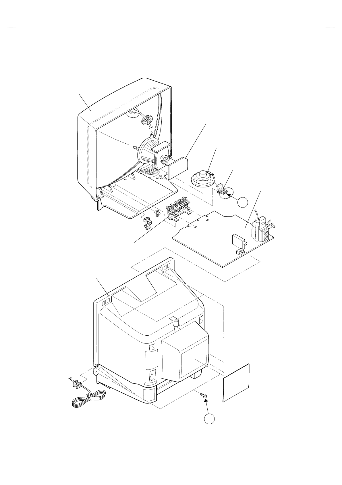
FRONT CABINET
C-13210
C-13211
CRT SOCKET PWB
(Within MAIN PWB)
SPEAKER
SPEAKER HOLDER
MAIN PWB
CONTROL KNOB
REAR COVER
B
Fig.1
No. 51783
A
(×5)
7
Page 8

C-13210
(CW)
C-13211
MEMORY IC REPLACEMENT
1. Memory IC
This model use a memory IC.
This memory IC stores data for proper operation of the video and deflection circuits.
When replacing, be sure to use an IC containing this (initial value) data.
2. Memory IC replacement procedure
Procedure Screen display
(1) Power off
Switch off the power and disconnect the power cord from the outlet.
(2) Replace the memory IC
Initial value must be entered into the new IC.
(3) Power on
Connect the power cord to the outlet and switch on the power.
(4) System constant check and setting
1) Press
SLEEP TIMER
” is being displayed, press
MIN.
key and, while the indication of “
DISPLAY
key and
VIDEO STATUS
SLEEP TIMER 0
on the remote control unit simultaneously.
2) The SERVICE MENU screen of Fig.1 is displayed.
3) While the SERVICE MENU is displayed, again simultaneously press
the DISPLAY and VIDEO STATUS keys to display t he Fig.2 SYSTEM
CONSTANT screen.
4) Refer to the SYSTEM CONSTANT table and check t he setting items.
Where these differ, select the setting item with the MENU UP/DOWN
key and adjust the setting with the MENU LEFT/RIGHT keys. (The
letters of the selected item are displayed in yellow.)
5) After adjusting, release the MENU LEFT/RIGHT key to store the setting
value.
6) Press the EXIT key twice to return the normal screen.
(5) Receive channel setting
Refer to the OPERATING INSTRUCTIONS(USER'S GUIDE) and set the
receive channels (Channels Preset) as described.
(6) User settings
Check the user setting items according to Table 2.
Where these do not agree, refer to the OPERATING INSTRUCTIONS
(USER'S GUIDE) and set the items as described.
key
SERVICE MENU
PICTURE
GAME
LOW LIGHT HIGH LIGHT
RF AFC CHK
VCO
SELECT BY EXIT BY
OPERATE BY EXIT
Fig.1
SYSTEM CONSTANT
MODEL :
V-CHIP : YES
CAN V-CHIP : YES
********-*****
********-*****
********-*************-*****
SELECT BY EXIT BY
OPERATE BY EXIT
*******
*******
**************
Fig.2
Indicated Model No.
(7) SERVICE MENU setting
Verify what to set in the SERVICE MENU, and set whatever is
necessary.(Fig.1) Refer to the SERVICE ADJUSTMENT for setting.
8
No. 51783
Page 9

TABLE 1 (System Constant setting)
Setting item Setting content Setting value
C-13210
C-13211
MODEL
V-CHIP YES
CAN V-CHIP YES
Display the each application model
YES NO
YES
NO
TABLE 2 (User setting value)
Setting item Setting value
1. Use remot e controller k eys
POWER
CHANNEL
CHANNEL PRESET
VOLUME
INPUT (TV/VIDE O )
DISPLAY
SLEEP TIMER
VIDEO STATUS
2. Setting of MENU
TINT
COLOR
PICTURE
BRIGHT
DETAIL
NOISE MUTING
SET VIDEO STATUS
SET CLOCK
ON/OFF TIMER
LANGUAGE
CLOSED CAPTION
BACKGROUND
AUTO TUNER SETUP
CHANNEL SUMMARY
V-CHIP
SET LOCK CODE
OFF
CH 02
See OPERATING INSTRUCTIONS.
10
TV
OFF
0
STANDARD
CENTER
CENTER
CENTER
CENTER
CENTER
ON
ALL CENTER
Unnecessary to set
NO
ENG
OFF
BLACK
TUNER MODE : AIR
Unnecessary to set
OFF
Unnecessary to set
Comformable model name
No. 51783
9
Page 10

C-13210
C-13211
SERVICE ADJUSTMENTS
ADJUSTMENT PREPARATION:
1. You can make the necessary adjustments for this unit with
either the Remote Control Unit or With the adjustment tools
and parts as given below.
2. Adjustment with the Remote Control Unit is made on the
basis of the initial setting values, however, the new setting
values which set the screen to its optimum condition may
differ from the initial settings.
3. Make sure that AC power is turned on correctly.
4. Turn on the power for set and test equipment before use, and
start the adjustment procedures after waiting at least 30 minutes.
5. Unless otherwise specified, prepare the most suitabl e reception
or input signal for adjustment.
6. Never touch any adjustment parts which are not specified in the
list for this adjustment - variable resistors, transformers,
condensers, etc.
7. Presetting before adjustment.
Unless otherwise specified in the adjustment instructions, pres et
the following functions with the remote control unit:
VIDEO STATUS STANDARD
TINT/COLOR
PICTURE/BRIGHT
DETAIL
CENTER
ADJUSTMENT EQUIPMENT
1. DC voltmeter (or digit al voltmeter)
2. Oscilloscope
3. Signal generator (Patt ern generator)[NTSC
]
4. Remote control unit
5. TV audio multiplex signal generator.
6. Frequency counter
ADJUSTMENT LOCATIONS
MAIN PWB
S756
POWER
PW
F901
ON
TIMER
REMOCON
RECEIVER
+
VOL
TP-12B
-
IC701
ADJUSTMENT ITEMS
Adjustment items Adjustment items
B1 POWER SUPPLY
IF VCO
RF. AGC SUB BRIGHT
FOCUS SUB CONTRAST
V. SIZE SUB COLOR
H. POSITION SUB TINT
FRONT
CRT SOCKET PWB
MENU
-
+
CH
IC702
S
(Within MAIN PWB ASS'Y)
TP-E
TP-R
T
WHITE BALANCE
(Low Light)
WHITE BALANCE
(High Light)
(SOLDER SIDE)
TOP
E1
U
CRT EARTH
(BRAIDED ASS'Y)
10
TP-91
(B1)
TP-E
( )
DEG
R926
IC921
F902
T161
VIDEO
IN
CW
TUNER
AUDIO
T131
IN
CW
IC201
T
X
U
C
HV
T522
UPPER : FOCUS
LOWER : SCREEN
No. 51783
Page 11

BASIC OPERATION SERVICE MENU
1.
TOOL OF SERVICE MENU OPERATION
Operate the SERVICE MENU with the REMOTE CONTROL UNIT.
2.
SERVICE MENU ITEMS
In general, basic setting(adjustments) items or verific ations are performed in the SERVICE MENU.
"
PICTURE
"
GAME
"
LOW LIGHT
"
HIGH LIGHT
"
RF AFC CHK
"
VCO (CW)
3. Basic Operations of the SERVICE MENU
(1) How to enter the SERVICE MENU.
Press
STATUS
(2) SERVICE MENU screen selection
Press the UP / DOWN key of the MENU to select any of the following items.
(The letters of the selected items are displayed in yellow.)
・・・・・・・・・・・・・・・・・・・・
・・・・・・・・・・・・・・・・・・・・・・・
・・・・・・・・・・・・・・・・・・
・・・・・・・・・・・・・・・・・
・・・・・・・・・・・・・・・・・
・・・・・・・・・・・・・・・・・・・
SLEEP TIMER
key and, while the indication of “
This sets the setting values (adjustment values) of the VIDEO/CHROMA and DEFLECTION circuits.
This is used when the GAME MODE is adjusted.
This sets th e setting values (ad justm ent values) of the WHI T E BALAN CE circuit.
This sets th e setting values (ad justm ent values) of the WHI T E BALAN CE circuit.
This is used when the IF VCO is adjusted.
This is used when the IF VCO is adjusted.
SLEEP TIMER 0 MIN.
key on the remote control unit simultaneously to enter the
●
PICTURE
●
GAME
●
LOW LIGHT
●
RF AFC CHK
●
VCO(CW)
●
HIGH LIGHT
[Do not adjust]
” is being displayed, press
SERVICE MENU
screen ① shown in the next figure page.
DISPLAY
C-13210
C-13211
key and
VIDEO
(3) Enter the any setting ( adjustment ) mode
"
PICTURE mode
1) If select any of PICTURE item, and the LEFT / RIGHT key is pressed from SERVICE MENU ( MAIN MENU ), the screen ② will be
displayed as shown in figure page later.
2) Then the UP / DOWN key is pressed, the PICTURE mode screen ③ is displayed, and the PICTURE setting can be performed.
"
GAME, LOW LIGHT, HIGH LIGHT, RF AFC CHK and VCO (CW) mode
1) If select any of GAME / LOW LIGHT / HIGH LIGHT / RF AFC CHK / VCO (CW) items, and the LEFT / RIGHT key is pressed from
SERVICE MENU ( MAIN MENU ), the screens ④ ⑤ ⑥ ⑦ ⑧ will be displayed as shown in figure page later.
2) Then the settings or verifications can be performed.
No. 51783
11
Page 12

C-13210
)
C-13211
SERVICE MENU (MAIN MENU
①①①①
SERVICE MENU
PICTURE
GAME
LOW LIGHT HIGH LIGHT
RF AFC CHK
VCO(CW)
SELECT BY
OPERATE BY
HIGH LIGHT MODE
⑥⑥⑥⑥
HIGH LIGHT
***
***
******
RF AFC CHK MODE [DO NOT ADJUST]
⑦⑦⑦⑦
EXIT BY
***
***
******
EXIT BY
EXIT
EXIT
SCREEN
②②②②
1. BRIGHT
STATUS
IT
IT
SELECT BY
EXIT BY
EXIT
IT
SELECT BY
OPERATE BY
PICTURE MODE
③③③③
***
***
******
********
********
****************
EXIT BY
EXIT
IT
RF AFC
FINE
STATUS
SELECT BY
OPERATE BY
VCO (CW) MODE
⑧⑧⑧⑧
TOO HIGH
ABOVE REFERENCE
BELOW REFERENCE
TOO LOW
SYNC : YES
***
***
******
********
********
****************
EXIT BY
EXIT
EXIT BY
EXIT
ON
IT
GAME MODE
④④④④
TINT
COLOR
PICTURE
BRIGHT
DETAIL
IT
SELECT BY
OPERATE BY
BRIGHT
BRIGHT
***
***
******
***
***
******
***
***
******
***
***
******
***
***
******
LOW LIGHT MODE
⑤⑤⑤⑤
*** *** ***
*** *** ***
*** *** ****** *** ***
***
***
******
EXIT BY
EXIT
EXIT BY
EXIT
IT
IT
12
No. 51783
Page 13

(4) Setting method
1) UP / DOWN key of the MENU
Select the SETTING ITEM.
2) LEFT / RIGHT key of the MENU
Setting(adjust) the SETTING VALUE of the SETTING ITEM.
When the key is released the SETTING VALUE will be stored
(memorized).
3) EXIT key
Returns to the previous screen.
(5) Releasing SERVICE MENU
1) Af ter returning to the SERVICE MENU upon completion of the
setting (adjustment) work, press the EXIT key again.
★
The settings for LOW LIGHT and HIGH LIGHT are described in the
WHITE BALANCE page of ADJUSTMENT.
★
The setting for VCO(CW) are described in the IF VCO page of
ADJUSTMENT.
1. BRIGHT
STATUS
SELECT BY
OPERATE BY
PICTURE MODE
SETTING
ITEM
TINT
COLOR
PICTURE
BRIGHT
DETAIL
SELECT BY
OPERATE BY
***
***
******
***
***
******
***
***
******
***
***
******
***
***
******
***
***
******
********
********
****************
EXIT BY
EXIT
EXIT BY
EXIT
C-13210
C-13211
IT
INITIAL
SETTING VALUE
↓ (Adjust)
SETTING VALUE
IT
GAME MODE
The letter of the selected
Items are displayed in yellow.
No. 51783
13
Page 14

C-13210
C-13211
INITIAL SETTING VALUE OF SERVICE MENU
1. Adjustment of the SERVICE MENU is made on the basis of the initial setting values; however, the new setting values which set the screen
in its optimum condition may differ from the initial setting.
2. Do not change the initial setting values of the setting (Adjustment) items not listed in “ADJUSTMENT”.
""""
PICTURE MODE
$
The four setting items in the video m ode No.7 EXT BRI., No.8 EXT PIC., No.11 EXT TINT and No.12 EXT COL. are linked to the items in
the TV MODE No.1 BRIGHT, No.2 PICTURE, No. 5 TINT and No.6 COLOR, respectively. When the setting items in the TV mode are
adjusted, the values in the setting items i n the video m ode are revis ed automatically to the same values in the TV mode.(The initial setting
values given in ( ) are off-set values.)
$
When the four items (No.7, 8, 11 and 12) are adjusted in the video mode, the setting values in each item are revised independently.
No. Setting (Adjustment) items Variable range initial setting value
1. BRIGHT 0 ~ 127 64
2. PICTURE 0 ~ 127 60
3. TV DTL(TV DETAIL) 0 ~ 63 23
4. TV BPF(TV B.P.FILTER) 0 / 1 0
5. TINT
6. COLOR
7. EXT BRI.(EXT.BRIGHT)
8. EXT PIC.(EXT.PICTURE)
9. EXT DTL(EXT.DETAIL)
10. EXT BPF(EXT.B.P.FILTER) 0 / 1 0
11. EXT TINT
12. EXT COL.(EXT.COLOR)
13. V SIZE
14. V CENT.(V.CENTER)
15. H POS.(H.POSITION)
16. OSD HP (OSD H POSITION)
17. OSD VP (OSD V POSITION)
18. H AFC 0 / 1 0
19. RF AGC 0 ~ 63 40
0 ~ 127
0 ~ 127
±
25
±
25
0 ~ 63
±
25 (+9)
±
25
0 ~ 63
0 ~ 7
0 ~ 31
0 ~ 31
0 ~ 15
57
55
(-2)
(-2)
25
(+3)
20
0
20
23
14
14
No. 51783
Page 15

"
GAME MODE
C-13210
C-13211
Setting (Adjustment) item Variable range initial setting value
TINT
COLOR
PICTURE
BRIGHT
DETAIL
"
LOW LIGHT MODE
Setting (Adjustment) item Variable range initial setting value
R CUTOFF
G CUTOFF
B CUTOFF
"
HIGH LIGHT MODE
Setting (Adjustment) item Variable range initial setting value
G DRIVE
B DRIVE
±
20
±
20
±
20
±
20
±
15
0 ~ 255
0 ~ 255
0 ~ 255
0 ~ 255
0 ~ 255
±
±
-10
-2
+10
20
20
20
128
128
0
0
"
RF AFC CHK MODE
Setting (Adjustment) item Variable range initial setting value
RF AFC
FINE
ON / OFF
-77 ~ +77
ON
±××
DO NOT
ADJUST
No. 51783
15
Page 16

C-13210
C-13211
■■■■
ADJUSTMENTS
B1 POWER SUPPLY
Item
Check of
B1 POWER
SUPPLY
Measuring
instrument
DC Voltmeter TP-91 (B1)
Test point Adjustment part Description
""""
TP-E(
)
ADJUSTMENT OF VIDEO / DEF. CIRCUIT
Item
IF VCO
adjustment
Measuring
instrument
Signal
generator
TOO HIGH
ABOVE REFERENCE
BELOW REFERENCE
TOO LOW
SYNC : YES
Test point Adjustment part Description
CW TRANSF. (T131)
[VCO(CW)] MODE
EXIT BY
IT
EXIT
YELLOW
1. Receive a black-and-white signal.
2. Connect the DC Voltmeter to TP-91 (B1) and TP-E(
3. Confirm that the voltage is DC134V
"
Under normal conditions, no adjustment is required.
1. Receive a NTSC broadcast. (use channels without offset
frequency).
2. Select the VCO(CW) mode from the SERVICE MENU.
3. Confirm the color change (yellow) from “TOO HIGH” to
“
TOO LOW”by CW TRANSF. and “SYNC : YES” being
shown on the screen. Then, adjust CW TRANSF. until
“
BELOW REFERENCE” mark turns yellow and confirm
again “ SYNC : YES” being shown on the screen.
+2V
-2.5V.
""""
).
RF. AGC
adjustment
FOCUS
adjustment
Signal
generator
No.19 RF AGC
FOCUS VR
[In HVT]
1. Receive a broadcast.
2. Select “No.19 RF AGC” of the PICTURE MODE.
3. Press the MUTE key and turn off color.
4. With the MENU LEFT key, get noise in the screen picture. (0
side of setting value)
5. Press the MENU RIGHT key and stop when noise disappears
from the screen.
6. Change to other channels and make sure that there Is no
irregularity.
7. Press the MUTE key and get color out.
1. Receive a crosshatch signal.
2. While looking at the screen, adjust FOCUS VR so that the
vertical and horizontal lines will be clear and in fine detail.
3. Make sure that the picture is in focus even when the screen
gets darkened.
16
No. 51783
Page 17

C-13210
C-13211
Item
V.SIZE
Adjustment
Screen
size
92%
H.POSITION
Adjustment
Measuring
instruments
Signal
generator
Picture size 100%
Signal
generator
Test point Adjustment part Description
No.13 V.SIZE
Screen size
Picture
size
100%
No.15 H POS.
1. Receive a crosshatch signal.
2. Select No.13 V SIZE in the PICTURE MODE.
3. Set the initial setting value of No.13 V SIZE with the LEFT /
RIGHT key of the MENU.
4. Adjust No.13 V SIZE until the verti cal screen si ze is 92%.
1. Receive a crosshatch signal.
2. Select the No.15 H POS. of the PICTURE MODE.
3. Set the initial setting value of the No.15 H POS. with the LEFT /
RIGHT key of the MENU.
4. Adjust the No.15 H POS. until the screen will be horizontally
centered.
No. 51783
17
Page 18

C-13210
C-13211
Item
WHITE
BALANCE
(Low Light)
Adjustment
Measuring
instruments
Signal
generator
R CUTOFF
BRIGHT
***
***
******
BRIGHT
REMOTE CONTROL UNIT
Test point Adjustment part Descrip ti on
[LOW LIGHT] MODE
BRIGHT
G CUTOFF
***
***
******
***
***
******
BRIGHT
R. CUTOFF
G. CUTOFF
B. CUTOFF
SCREEN VR
[In HVT]
B CUTOFF
***
***
******
EXIT BY
IT
EXIT
1. Receive a black-and-white signal. (Col or off )
2. Select the【LOW LIGHT】MODE from the SERVICE MENU.
3. Set the initial setting value of BRIGHT with the LEFT /
RIGHT key of the remote control unit.
4. Set the initial setting value of R CUTOFF, G CUTOFF and
B CUTOFF with the ④ to ⑨ key of the remote control
unit.
5. Display a single horizontal line by pressing the ①key of the
remote control unit.
6. Turn the screen VR all the way to the left.
7. Turn the screen VR gradually to the right from the left until
either one of the red, blue or green colors appears faintly.
2. A djust the two colors which did not appear until the single
horizontal line that is displayed becomes white using the
④
to ⑨ keys of the remote control unit.
9. Turn the screen VR to where the single horizontal line
glows faintly.
10. Press the ② key to return to the regular screen.
*
The ③ EXIT key is the cancel key for the WHITE
BALANCE.
WHITE
BALANCE
(High Light)
Adjustment
H.LINE ON EXITH.LINE OFF
1 2 3
R CUTOFF B CUTOFFG CUTOFF
R CUTOFF B CUTOFFG CUTOFF
Signal
generator
[HIGH LIGHT] MODE
G DRIVE
HIGH LIGHT
***
*** ***
******
54
6
987
G. DRIVE
B. DRIVE
1. Receive a black-and-white signal. (Col or off )
2. Select the【HIGH LIGHT】MODE in the SERVICE MENU.
3. Set the initial setting value of G DRIVE and B DRIVE with
the ⑤, ⑥, ⑧ and ⑨ keys of the remote control unit.
4. Adjust the screen until it becomes white using the ⑤, ⑥,
⑧
and ⑨ keys of the remote control unit.
*
B DRIVE
The ③ (EXIT) key is the cancel key for the WHITE
BALANCE.
Remote Control Unit
①
***
******
EXIT BY
EXIT
IT
key : H.LINE ON
②
key : H.LINE OFF
③
key : EXIT
⑤
key : G DRIVE
⑥
key : B DRIVE
⑧
key : G DRIVE
⑨
key : B DRIVE
▲
▲
▼
▼
18
No. 51783
Page 19

C-13210
C-13211
Item
SUB
BRIGHT
Adjustment
SUB
CONTRAST
Adjustment
SUB
COLOR
Adjustment
Measuring
instruments
Test point Adjustment part Description
No.1 BRIGHT
No.2 PICTURE
No.6 COLOR
1. Receive a broadcast.
2. Select No.1 BRIGHT of the PICTURE MODE.
3. Set the initial setting value of the No.1 BRIGHT with the
LEFT / RIGHT key of the MENU.
4. If the brightness is not best with the initial setting value,
make fine adjustment of the No.1 BRIGHT until you get the
optimum brightness.
1. Receive a broadcast.
2. Select No.2 PICTURE of the PICTURE MODE.
3. Set the initi al setting value of the No.2 PICTURE with the
LEFT / RIGHT key of the MENU.
4. If the contrast is not best with the initial setti ng value, m ake
fine adjustment of the No.2 PICTURE until you get the
optimum contrast.
1. Receive a broadcast.
2. Select No.6 COLOR of the PICTURE MODE .
3. Set the initial setting value of the No.6 COLOR with the
LEFT / RIGHT key of the MENU.
4. If the color is not best with the initial setting value, make fine
adjustment of the No.6 COLOR until you get the optimum
color.
SUB TINT
Adjustment
No.5 TINT
1. Receive a broadcast.
2. Select No.5 TINT of the PICTURE MODE.
3. Set the initial setting value of the No.5 TINT with the LEFT /
RIGHT key of the MENU.
4. If the tint is not best with the initial setting value, make fine
adjustment of the No.5 TINT until you get the optimum tint.
No. 51783
19
Page 20

C-13210
(
)
C-13211
PURITY, CONVERGENCE
PURITY ADJUSTMENT
1. Demagnetize CRT with the demagnetizer.
2. Loosen the retainer screw of the deflection yoke.
3. Remove the wedges.
4. Input a green raster signal from the signal generator, and turn
the screen to green raster.
5. Move the deflection yoke backward.
6. Bring the long lug of the purity magnets on the short lug and
position them horizontally. (Fig.2)
7. Adjust the gap between two lugs so that t he GREEN RASTER
will come into the center of the screen. (Fig.3)
8. Move the deflection yoke forward, and fix the position of the
deflection yoke so that the whole screen will become green.
9. Insert the wedge to the top side of the deflection yoke so that it
will not move.
WEDGE
CRT
%
P/C MAGNETS
P : PURITY MAGNET
4 : 4 POLES
6 : 6 POLES
(convergence magnets)
(convergence magnets)
Fig.1
PURITY MAGNETS
DEFLECTION
YOKE
P
46
P / C
MAGNETS
10. Input a crosshatch signal.
11. Verify that the screen is horizontal.
12. Input red and blue raster signals, and m ake sure that purity is
properly adjusted.
Long lug
Short lug
FRONT VIEW
Bring the long lug over the short lug
and position them horizontally.
Fig.2
GREEN RASTER
CENTER
Fig.3
20
No. 51783
Page 21

STATIC CONVERGENCE ADJUSTMENT
(
)
(
)
(
)
1. Input a crosshatch signal.
2. Using 4-pole convergence magnets, overlap the red and blue
lines in the center of the screen (Fig.1) and turn them to
magenta (red/blue).
3. Using 6-pole convergence magnets, overlap the
magenta(red/blue) and green lines in the center of t he screen
and turn them to white.
4. Repeat 2 and 3 above, and make best convergence.
DYNAMIC CONVERGENCE ADJUSTMENT
1. Move the deflection yoke up and down and overlap the lines in
the periphery. (Fig. 2)
2. Move the deflection yoke left to right and overlap the lines in the
periphery. (Fig. 3)
3. Repeat 1 and 2 above, and make best convergence.
FRONT VIEW
FRONT VIEW
BLUE
GREEN
RED
RED
Fig.1
GREEN
C-13210
C-13211
BLUE
RED
GREEN
BLUE
●
After adjustment, fix the wedge at the original posit i on.
Fasten the retainer screw of the deflection yoke.
Fix the 6 magnets with glue.
FRONT VIEW
GREEN
RED
BLUE
BLUE
GREEN RED
Fig.2
BLUE
Fig.3
GREEN
RED
RED
GREEN
BLUE
BLUE
GREEN
RED
No. 51783
21
Page 22

C-13210
C-13211
HOW TO CHECK THE HIGH VOLTAGE HOLD DOWN CIRCUIT
1. HIGH VOLTAGE HOLD DOWN CIRCUIT
After repairing the high voltage hold down circuit shown in Fig. 1.
This circuit shall be checked to operate correctly.
2. CHECKING OF THE HIGH VOLTAGE HOLD DOWN CIRCUIT
(1) Turn the POWER SW ON.
(2) As shown in Fig. 1, set the resistor (between X connector 1 & 3 ).
(3) Make sure that the screen picture disappears.
(4) Temporarily unplug the power cord.
(5) Remove the resistor (between X connector 1 & 3 ).
(6) Again plug the power cord, make sure that the normal picture is displayed on the screen.
POWER
ON OFF
D958
D563
12V
R953
Q561
R564
Q951
RY901
Q562
12V
C562
D562
RESISTOR
14.46k
Ω±
Ω±
Ω±Ω±
3 2 1
R563
Fig. 1
R562
1%1/4W
C561
CONNECTOR
X
D561
HEATER
HVT
4
R561
22
No. 51783
Page 23

SELF CHECK FUNCTIONS
1. Outline
This model has self check functions given below. When a malfunction has been detected, the POWER is turned off and the LED flashes to
inform of the failure . The malfunction is detected by the signal input state of the control line connected to the microcomputer.
2. Self check items
Check item Details of detection Method of detection State of malfunction
C-13210
C-13211
CRT NECK protector
Also detected if the
power supply line output
from the HVT (High
voltage Transformer) has
shorted with the ground.
3. Self check indicating function
The self-check function begins detection about 5 seconds after
power is supplied.
In the event a malfunction is detected, the power is cut off
immediately.
At this time, the ON-TIMER LED flashes to inform of the
malfunction.
[ON-TIMER LED indication]
The ON-TIMER LED flashes at 0.5 seconds intervals.
When the vertical circuit Scorrection capacitor C427
is shorted, detect the
potential drop of the C427,
and prevent the burn
damage to the CRT NECK.
(Grounding of shorting of
the power supply output
from the HVT to the vertical
circuit, and the small signal
power supply is also
detected.)
The microcomputer detects at 1
second intervals.
If NG is detected for more than 1
ms, a malfunction is interpreted.
POWER
Supplied
After about
5 seconds
Start of
detection
When a malfunction has been
detected, the POWER is turned
off. While the POWER is being
turned off , the power key of the
remote controller is not operational
until the power code is taken out
and put in again.
Malfunction
is detected
POWER OFF
Flashing
ON-TIMER LED
No. 51783
23
Page 24

C-13210
C-13211
24
No. 51783
Page 25

JVC SERVICE & ENGINEERING COMPANY OF AMERICA
DIVISION OF JVC AMERICAS CORP.
Head office
East Coast
Midwest
West Coast
Southwest
Hawaii
Southeast
: 1700 Valley Road, Wayne, New Jersey 07470 (973)315-5000
: 10 New Maple Avenue, Pine Brook, New Jersey 07058 (973)396-1000
: 705 Enterprise St. Aurora, Illinois 605 04 (630)851-7855
: 5665 Corporate Avenue, Cypress, California 90630 (714)229-8011
: 10700 Hammerly, Suite 105, Houston,Texas 77043 (713)935-9331
: 2969 Mapunapuna Place, Honolulu, Hawaii 96819 (808)833-5828
: 1500 Lakes Parkway, Lawrenceville, Georgia 30243 (770)339-2582
JVC CANADA INC.
Head office
Vancouver
#
: 21 Finchdene Square Scarborough, Ontario M1X 1A7 (416)293-1311
: 13040 Worster Court Richmond B.C. V6V 2B3 (604)270-1311
4
C-13210S-UCM #5
C-13211S-UCM #4
Printed in Japan
VP 0101
DP3051
 Loading...