

Page 1
DV VIDEO CASSETTE RECORDER
DV VIDEOKASSETTENREKORDER
ENREGISTREUR A CASSETTE DIGITAL VIDEO
DV VIDEOREGISTRATORE
UNIDAD GRABADORA DE VÍDEO DV
INSTRUCTION MANUAL
BR-DV3000E
BEDIENUNGSANLEITUNG
MODE D’EMPLOI
ISTRUZIONI PER L’USO
MANUAL DE INSTRUCCIONES
EnglishItaliano Español Français Deutsch
OPERATE
Mini
PROFESSIONAL
A.DUB
INPUT SEL.REMOTE SEL.MIC
SERIAL
LINE
9PIN
WIRELESS
DV
DVCAM NTSC
CH-1/3
CH-2/4
Y/C
Thank you for purchasing this JVC product.
Before operating this unit, please read the
instructions carefully to unsure the best
possible performance.
BR-DV3000
EJECT
STOP
MENIU
PAUSE
SET
FF
LLT0025-001F
PAL
REC INH.
REC PLAY
REW
Page 2
Supplement
This equipment is in conformity with the provisions and protection requirements of the
corresponding European Directives. This equipment is designed for professional video
appliances and can be used in the following environments:
Residential (including both of the location type class 1 and 2 found in IEC 1000-2-5)
5
5
Commercial and light industrial (including, for example, theatres)
5
Urban outdoors (based on the definition of location type class 6 in IEC 1000-2-5)
This apparatus is designed for rack mounting or is used close to other apparatus.
In order to keep the best performance and furthermore for electromagnetic compatibility
we recommend to use cables not exceeding the following lengths:
Port Cable Length
AUDIO SHIELDED CABLE 10 meters
LINE COAXIAL CABLE 10 meters
Y/C COAXIAL CABLE 10 meters
DV SHIELDED TWIST PAIR CABLE 4 meters
REMOTE TWIST PAIR CABLE 5 meters
The inrush current of this apparatus is 12.1 amperes.
Caution:
5 Where there are strong electromagnetic waves or magnetism, for example near a radio
or TV transmitter, transformer, motor, etc., the picture and sound may be disturbed. In
such a case, please keep the apparatus away from the sources of the disturbance.
Dear Customer,
This apparatus is in conformance with the valid European directives and standards
regarding electromagnetic compatibility and electrical safety.
European representative of Victor Company of Japan Limited. is:
JVC Technical Services Europe GmbH
Postfach 10 05 04
61145 Friedberg
Germany
E-2
Page 3
SAFETY PRECAUTIONS
Warning Notice
FOR YOUR SAFETY (Australia)
1. Insert this plug only into effectively earthed
three-pin power outlet.
2. If any doubt exists regarding the earthing,
consult a qualified electrician.
3. Extension cord, if used, must be three-core
correctly wired.
IMPORTANT (In the United Kingdom)
Mains Supply (AC 230 V
WARNING – THIS APPARATUS
MUST BE EARTHED
The wires in this mains lead are coloured in
accordance with the following code;
GREEN-and-YELLOW : EARTH
BLUE : NEUTRAL
BROWN : LIVE
As the colours of the wires in the mains lead of
this apparatus may not correspond with the
coloured markings identifying the terminals in
your plug, proceed as follows.
The wire which is coloured GREEN-ANDYELLOW must be connected to the terminal in
the plug which is marked with the letter E or by
the safety earth symbol or coloured GREEN
or GREEN-AND-YELLOW. The wire which is
coloured BLUE must be connected to the terminal
which is marked with the letter N or which is
coloured BLACK. The wire which is coloured
BROWN must be connected to the terminal
which is marked with the letter L or coloured
RED.
``
`)
``
POWER SYSTEM
Connection to the mains supply
This unit operates on voltage of 220 V to
240 V AC, 50 Hz/60 Hz.
WARNING:
TO REDUCE THE RISK OF FIRE OR
ELECTRIC SHOCK, DO NOT EXPOSE
THIS APPLIANCE TO RAIN OR
MOISTURE.
CAUTION
To prevent electric shock, do not open the
cabinet. No user serviceable parts inside. Refer
servicing to qualified service personnel.
Note:
The rating plate and the safety caution are on
the rear of the unit.
The OPERATE button does not completely
shut off mains power from the unit, but switches
operating current on and off.
WARNING
It should be noted that it may be unlawful to rerecord pre-recorded tapes, records, or discs
without the consent of the owner of copyright in
the sound or video recording, broadcast, or
cable programme and in any literary, dramatic,
musical or artistic work embodied therein.
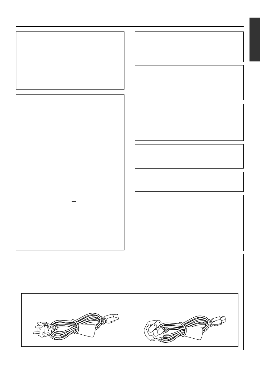
Caution for AC Mains Lead
FOR YOUR SAFETY PLEASE READ THE FOLLOWING TEXT CAREFULLY.
This product is equipped with 2 types of AC cable. One is for continental Europe, etc. and the other one
is only for U.K.
Appropriate mains cable must be used in each local area, since the other type of mains cable is not
suitable.
FOR CONTINENTAL EUROPE, ETC.
Not to be used in the U.K.
FOR U.K. ONLY
If the supplied plug is not suitable for your
socket outlet, it should be cut off and fitted
with an appropriate one.
E-3
Page 4
Thank you for purchasing our DV
Video Cassette Recorder BR-DV3000.
As this is a DV-format video cassette recorder,
video cassettes with the or logos can
be used with it.
DVCAM cassettes can be recorded in DV format.
This VTR features dual support for NTSC and PAL.
Certain functions however, are supported by only
one signal system. They are indicated with (NTSC
only) or (PAL only).
● In order to prevent crumpling due to tape
slack, please do not perform important recording within the first and last 2 – 3 minutes run
of the tape.
● Recorded video (music) is meant for personal
entertainment only and must not be used for
other purposes without the prior consent of
the copyright owner.
● Our company shall not guarantee the content
of any recording effort should this VTR fail to
record normally due to defects, either of the
main unit itself or the video cassette tape.
E-4
MAIN FEATURES
● DV format
High picture and sound quality by digital technology.
● Compatible mechanisms for standard/mini
DV cassettes
It records on and plays back DV cassettes of the
standard and mini size. (SP mode only)
DVCAM cassettes can be recorded in DV format.
A tape recorded with the DVCAM format can be
used only for playback for this VTR.
● Equipped with composite and Y/C input &
output terminal devices.
●
Equipped with DV IN/OUT terminals. (IEEE1394)
It can exchange digital signals with IEEE1394compatible devices.
● Dual support for NTSC/PAL
Switch between NTSC or PAL as required. This
makes it easy to work with internationally
sourced material and transfer it to a non-linear
system for editing. You can also record to Standard DV or Mini DV tape in either NTSC or PAL
system.
● Wireless/wired remote control
It can be controlled with the provided wireless
remote controller or the optional wired remote
controller RM-G30.
● Support for RS-422A interface
It can be used as a player for an editing system
that uses the RS-422A-compatible editing remote controller RM-G820.
● Recording/playback of time codes
● Audio-dubbing (after-recording) function
Audio dubbing at a sampling frequency of 32kHz
is allowed on CH3 and CH4 (except during DV
input).
● Backup recording function
By linking with other DV devices, long-duration
continuous recording is possible.
● Indexed search and blank search function
It can search for indexed signal recorded positions or unrecorded parts.
● Repeat play function
There are 3 types of repeat function. (INDEX/
VIDEO END/ TAPE END)
● Can be placed in an upright position
With the use of the provided stand, it can be
positioned upright.
Page 5

TABLE OF CONTENTS
INTRODUCTION
Precautions .................................................... 6
Daily maintenance and regular inspection ..... 7
Precautions on the use of cleaning tape ........ 8
Cassette tape ................................................. 8
Condensation ................................................. 9
NAMES AND FUNCTIONS OF VARIOUS PARTS
Front panel ................................................... 10
Rear panel .................................................... 14
Wireless remote controller ........................... 16
ON-SCREEN DISPLAY
Regarding on-screen display........................ 18
Status display ............................................... 19
Event display ................................................ 21
Alarm display ................................................ 22
PREPARATION
Provided wireless remote controller ............. 24
Power ........................................................... 26
Selecting the NTSC/PAL signal system ....... 28
OPERATION LOCK mode ............................ 29
Loading/ejecting cassettes ........................... 30
Setting/displaying date and time .................. 31
EDIT
Using the unit in an editing system .............. 50
MENU SCREEN
Structure of the menu ................................... 53
Setting the menu .......................................... 54
Contents of the menus ................................. 56
OTHERS
Placing the unit in an upright position .......... 65
Warning display............................................ 66
Troubleshooting ............................................ 68
Checking the hour meter .............................. 69
Specification ................................................. 70
RECORDING
Connection and setting ................................ 34
Setting time codes ........................................ 36
Recording method ........................................ 38
Audio dubbing .............................................. 39
Backup recording function ............................ 40
Recording using the serial remote terminal ...
PLAYBACK
Connection/setting ....................................... 42
Basic playback method ................................ 44
Special playback function ............................. 45
Locate function ............................................. 47
Repeat playback........................................... 48
Selecting playback audio output................... 49
41
E-5
Page 6

INTRODUCTION
Precautions
Place of storage and use
Please avoid storing or using this VTR in the following places:
● Extremely hot or cold places beyond the allowable temperature for operation (5˚C – 40˚C).
● Humid or dry places beyond the allowable humidity range for operation (30% –80% RH).
● Dusty or sandy places.
● Places exposed to oil, smoke or steam, such
as the kitchen vicinity.
● Intensely vibrating or unstable places.
● Places prone to condensation.
● Places that generate strong magnetic fields,
e.g., transformer or motor.
● Places near devices that generate electric
waves, e.g., transceiver or mobile phone.
● Places that generate radiation, X-rays or corrosive gases.
Handling the unit
● Please do not place heavy objects on the VTR,
like a monitor or TV.
● Please do not insert foreign objects into the
cassette slot.
● Mind your finger when loading the cassette.
Please be careful not to get your fingers
clamped when loading the cassette to prevent
injury.
● Place this VTR out of reach of young children.
As injury may result from fingers getting
clamped when loading the cassette, please
keep this VTR out of reach of young children.
● Please do not block the ventilation openings.
● Avoid violent shocks to the unit. Do not drop
the unit.
● Please remove the cassette tape from the cassette slot when transporting the unit.
● Please remove the AC adapter to save energy when the unit is not in use.
Maintaining the unit (Please turn off the
power before performing maintenance
work.)
Please wipe the unit with a soft cloth. Do not wipe
it with thinner or benzene lest the surface melts
or becomes dull. For stubborn stains, wipe first
with a water-diluted neutral detergent and then
wipe dry.
Please use the provided AC adapter to
connect the VTR to a power source.
Use the supplied power cord. Using a
different type or damaged cord may
cause fire or electric shock.
E-6
Page 7
Daily maintenance and regular inspection
This unit uses consumables or components that will wear off. If a worn-out or deteriorated component
continues to be used, it may cause the unit to break down. To prevent this, please perform daily maintenance using the head-cleaning tape. With the head-cleaning tape alone, however, the entire tape-winding
mechanism cannot be completely cleaned.
Please perform regular maintenance of the components as shown below.
Regular inspection (maintenance)
The tasks of maintenance involved are similar to that of replacing the engine oil or tire of a car.
Depending on the number of usage hours, please clean, inspect or replace the components as
follows:
Number of hours 500H 1000H 1500H 2000H 4000H
Drum assembly (including head)
Head cleaner
Tape guide, roller
Reel disk • tension bands — —
Usage Time :You can check the drum usage time via the hour meter display.
For details, please refer to page 69, “Checking the hour meter”.
Maintenance consultation :For details on the maintenance plan and fee, please consult with
your nearest JVC-authorized service agent.
—:Inspection
: Cleaning, inspection and
adjustment
: Cleaning and inspection;
Replacement if necessary
: Replacement
Maintenance necessity and frequency depends on the environment and usage. The above information serves only as a guide.
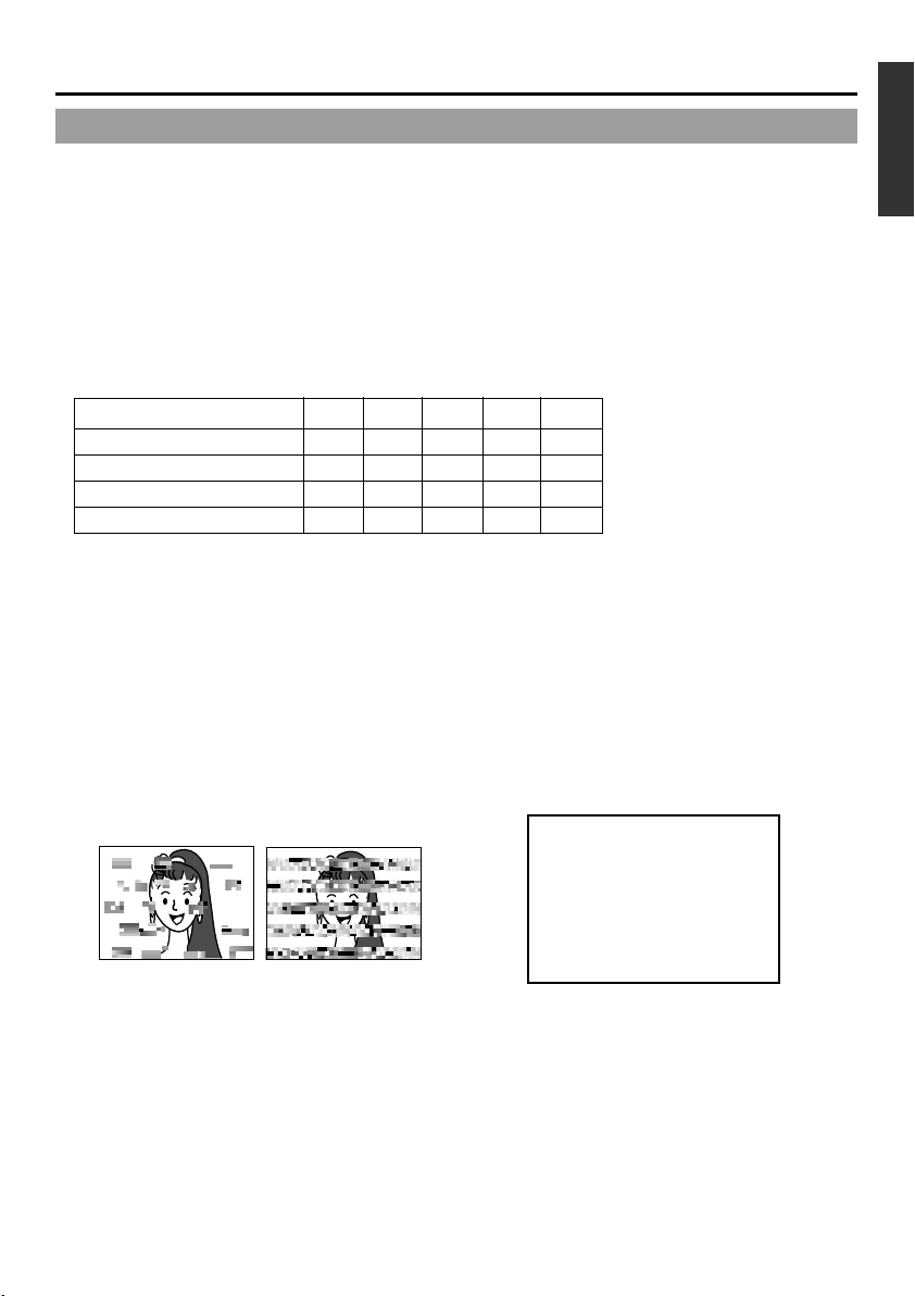
Head cleaning
● Recording or playing back with a stained head
will result in block noise or disrupted sound.
Please perform regular head cleaning to maintain superior image and sound quality.
Block noise
● For information on how to use the head cleaning
tape and the relevant precautions, please refer
to page 8, “Precautions on the use of cleaning
tape”.
● If dust adheres on the head, “HEAD CLEANING
REQUIRED!” will be displayed on the monitor
when this unit plays a tape.
HEAD CLEANING REQUIRED!
E-7
Page 8
INTRODUCTION
Precautions on the use of cleaning tape
Please use cleaning tape produced by JVC.
Please follow the instructions below when using the
cleaning tape.
1.
The tape will run for 10 seconds in the PLAY
mode. (Thereafter, it stops automatically and
enters the STOP mode.)
• After loading the cleaning tape, press the PLAY
button.
2.
For a single cleaning session, use it up to 4
times.
3.
Please refer to the following table as a guide for
cleaning.
Memo:
1. Under low humidity conditions, (10% RH to 30%
RH), please perform head cleaning at intervals
of half of the following stated periods.
2. If M-DV80 is used immediately after cleaning, the
VTR warning (“HEAD CLEANING
REQUIRED!”) may disappear only after the tape
has run for some time.
3. Please use the cleaning tape at room temperature (10˚C to 35˚C).
4. Instructions for using the cleaning tape are stated
inside its case. The contents may be slightly different from those stated here.
Please follow the instructions in this manual.
Operating environment
of the unit 5˚C to 10˚C 10˚C to 35˚C 35˚C to 40˚C
Guide for using 1 to 2 times every 1 to 2 times every 1 to 2 times every
cleaning tape 5 hours 20 to 30 hours 5 hours
Low temperature Room temperature High temperature
Cassette tape
This unit can record onto and playback standard
DV and mini DV cassette tapes (for SP mode only).
Please use the following JVC cassettes with the
or the logos.
●
●
Standard DV cassettes
LA-DV276
LA-DV186
LA-DV124
Mini DV cassettes
M-DV63PR0
M-DV60
M-DV30
Memo
● DVCAM cassettes can be recorded in DV format.
Tapes recorded in DVCAM format can be played
(SP Mode).
● M-DV80 cassettes(Mini DV 80min tape) cannot be
used with this unit.
Precautions on the use of tape
● Reverse sides of videotapes cannot be used.
● Please store the tape only after it has been fully rewound, so as to avoid damaging the tape.
● Please store the cassette in places low in humidity, well-ventilated and fungus-proof.
● When a cassette is used repeatedly, noise may increase due to e.g., dropout, etc. hence affecting its
performance. Please do not use dirty or damaged tapes as they will shorten the life span of the
rotation head.
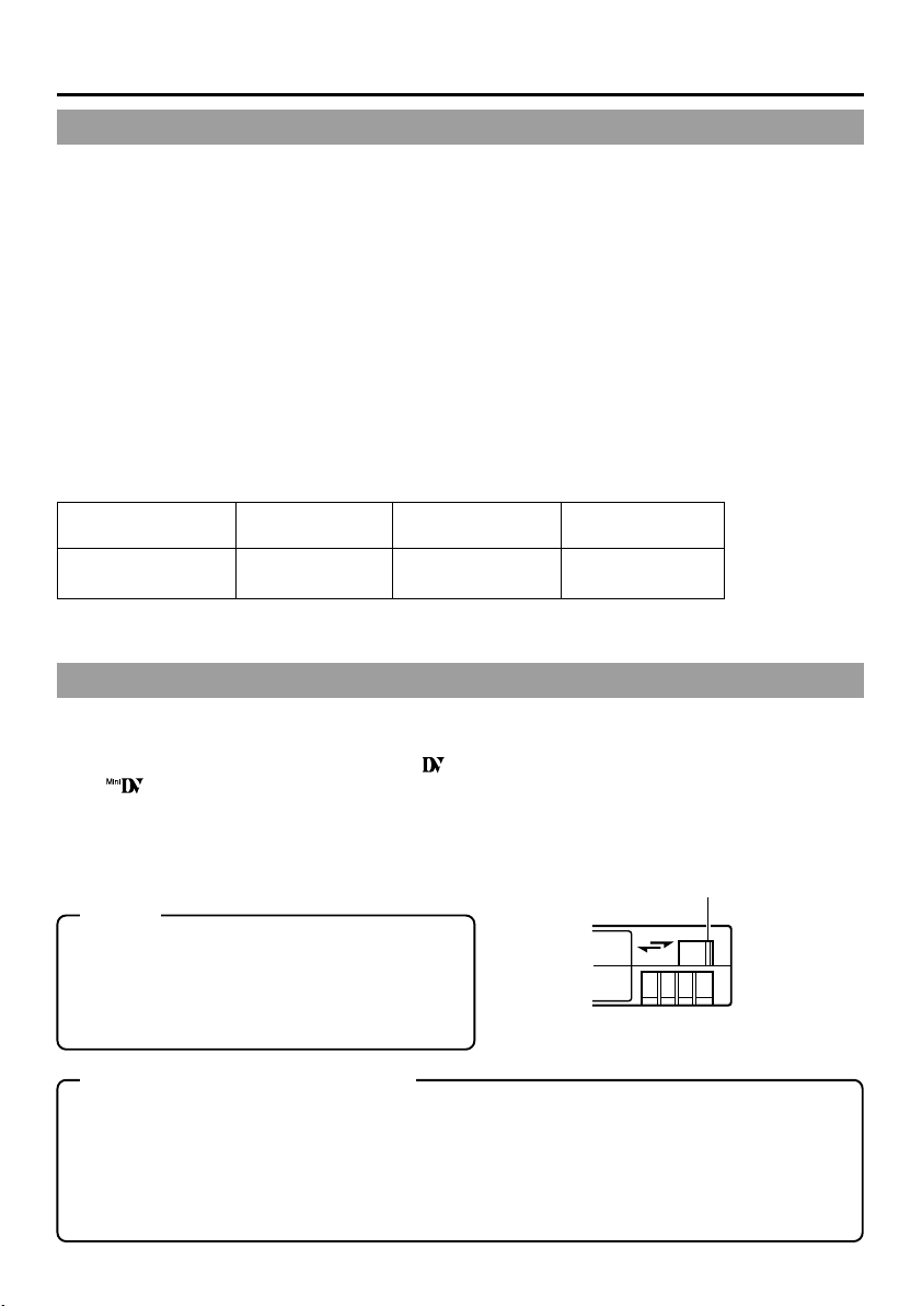
Erasure prevention
DV cassettes have a safety slide at the back to
prevent accidental erasure.
● To prevent accidental erasure of important
records, push the slide to the “SAVE” position.
● To record, push the slide to the “REC” position.
Slide
REC
SAVE
E-8
Page 9
For recording and storing videotapes in the best condition
Observe the following instructions for the best recording and storage of videotapes.
● Ta ke care of the conditions of handling videotapes.
It is recommended that you record and store videotapes in the environment below.
Storage
Recording Short period Long period
(Up to 10 years) (Over 10 years)
Temperature 17°C to 25°C 15°C to 23°C 15°C to 19°C
Humidity 30% to 70% 40% to 55% 25% to 35%
Hourly temperature change Less than 10°C – –
Hourly humidity change Less than 10% – –
● Do not leave the videotapes neglected for a long period.
If videotapes are left wound for a long period of time, it may result in distortion of the tape. Also it may
cause tape-to-tape adhesion (known as blocking). It is recommended that videotapes be unspooled and
rewound once a year for refreshing.
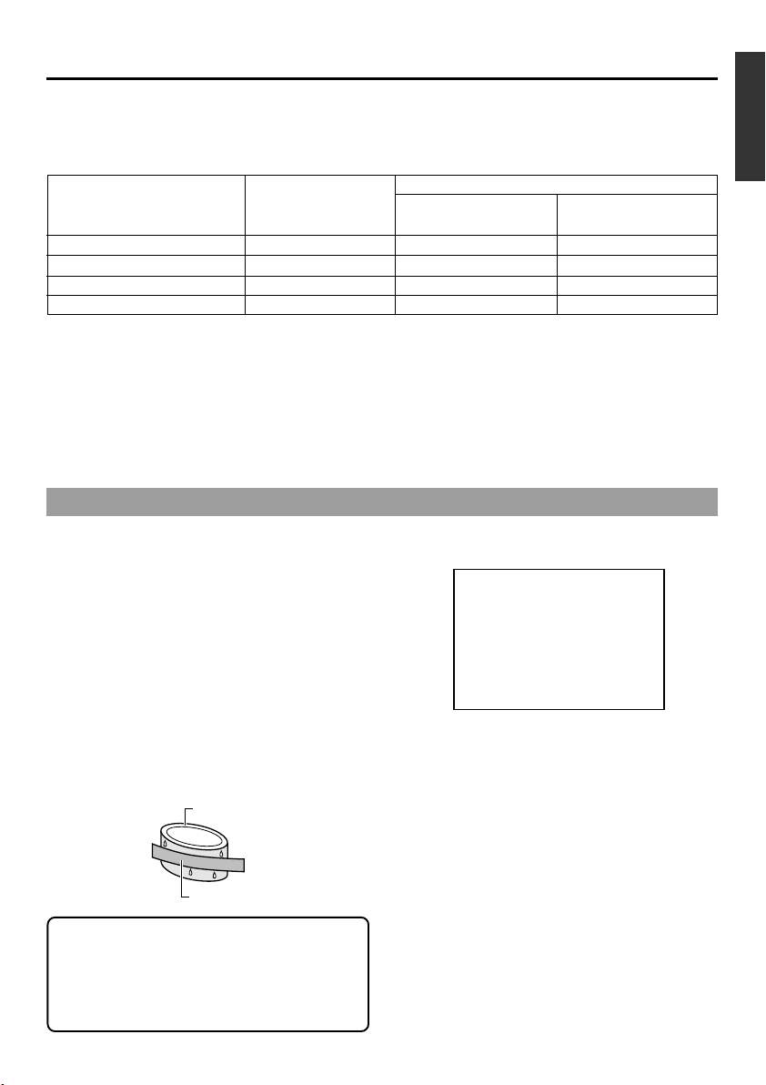
● When tapes are not in use, store them in cases and on end.
Storage cases protect videotapes from humidity, dust and ultraviolet. Keep tapes in cases and do not
store them lying flat. When housed in a horizontal position, pressure from other tapes can cause distortions and deformations of the tape edges.
Condensation
● When this unit is moved from a cold to a warm
place abruptly, the vapor in the warm air will come
into contact with the head drum or the tape
guides. When chilled, the vapor turns into droplets of water. This state is known as condensation. When condensation occurs, the videotape
will adhere to the head drum or the tape guides
and will be damaged.
● Condensation occurs on this unit in the following
circumstances:
• It is moved abruptly from a cold place to a warm
place.
• It is used in a room immediately after the heater
has been turned on, or when cold breeze from
an air-conditioner blows onto it.
• It is used at a place of high humidity.
Head drum
Videotape
● When condensation occurs, the monitor displays
the following warning:
CONDENSATION ON DRUM
To remedy, leave the unit with the power ON and
wait until the WARNING indicator disappears.
● Prevention of condensation
When transporting the BR-DV3000 from a cold
to a warmer place abruptly, first take out the cassette. Then place the BR-DV3000 in a plastic bag
and seal it before transporting the camera.
Leave the BR-DV3000 in the sealed plastic bag
until the camera has the same temperature as
the surroundings. This will prevent condensation.
When a cassette tape is loaded, please do not
transport e.g., from an external cold place to a
warm room thereby subjecting the unit to drastic temperature changes.
After moving the unit, please do not use it until
the innards are stabilized.
E-9
Page 10
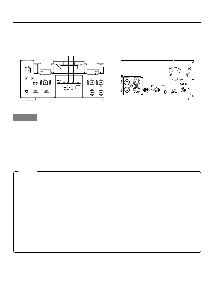
NAMES AND FUNCTIONS OF VARIOUS PARTS
– Front panel –
2
OPERATE
1
Mini
PROFESSIONAL
9PIN
SERIAL
WIRELESS
A.DUB
INPUT SEL.REMOTE SEL.MIC
DV
LINE
Y/C
43
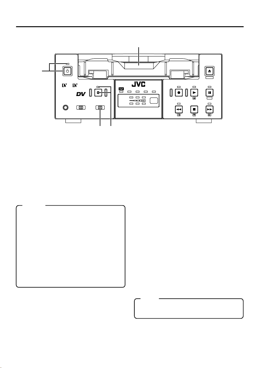
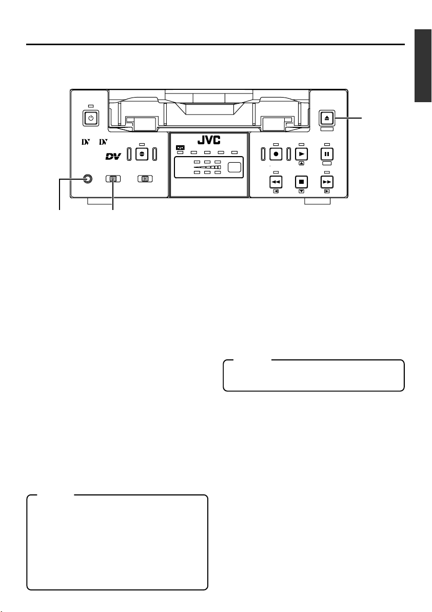
[OPERATE] Operate button/LED
1
● Press this button to turn on the power and operate the unit. (Operate ON)
Press this button again to turn off the power.
(Operate OFF)
● The OPERATE LED lights up as follows.
Operate ON : the LED lights up green
Operate OFF : the LED lights up red
VTR error : the LED blinks in red
Memo
● When the DC IN MODE item of the SYSTEM menu is set to “OPE ON” and power is
supplied to the 1 DC IN terminal located at
the rear panel, the unit goes into the OPERATE ON state even if this button is not
pressed.
● Even when the power has been turned off
with this button, a small amount of electricity will still be channeled into the unit.
Therefore, if the unit is not going to be used
for a long period of time, please remove the
AC adapter to reduce energy consumption.
Cassette slot
2
● Load a cassette into or unload it from the slot.
Please insert a standard DV or a mini DV cas-
sette. (☞ Page 30)
● When the unit is in the OPERATE OFF state
and if a cassette is loaded, it goes into the
ON state.
CH-1/3
CH-2/4
PAL
DVCAM NTSC
BR-DV3000
REC INH.
[A. DUB] Audio dubbing button/LED
3
REC PLAY
REW
STOP
● Press this button for audio dubbing (after-recording).
For audio dubbing, set the AUDIO MODE item
of the AUDIO/VIDEO menu to “32K”.
Sound produced by the 6 MIC terminal or
the 9 AUDIO IN terminal at the rear panel
(☞ Page 15) is recorded on CH3 and CH4
channels.
● During audio dubbing, the A. DUB LED lights
up red.
● If the INPUT SEL. switch is set at “DV”, audio
dubbing is not possible.
(☞ Page 39, “Audio dubbing”)
[INPUT SEL.] Input video signal se-
4
lection switch
● Select the video signal input with this switch.
Y/C : YC separate video signals from the Y/
C IN terminal
LINE : composite video signals from the LINE
IN terminal
DV :DV signals from the DV IN/OUT termi-
nal (IEEE1394)
Note
During recording, manipulating this switch will
not bring about any effect.
EJECT
MENIU
PAUSE
SET
FF
E-10
Page 11
OPERATE
Mini
PROFESSIONAL
EJECT
MENIU
A.DUB
INPUT SEL.REMOTE SEL.MIC
WIRELESS
LINE
DV
SERIAL
9PIN
CH-1/3
CH-2/4
Y/C
DVCAM NTSC
BR-DV3000
PAL
REC INH.
REC PLAY
REW
STOP
PAUSE
SET
FF
7
56
[REMOTE SEL.] Remote select
5
switch
Use this switch to select the remote controller
type.
9 PIN : Select this to use the RS-422A-
compatible editing remote controller (RM-G820) that connects
to the 4 9 PIN REMOTE terminal located at the rear panel.
Please use this unit as a player.
* This setting is valid only when
the REMOTE item of the REMOTE menu is set to ON.
SERIAL : Select this to use the serial re-
mote controller (RM-G30) that
connects to the 3 SERIAL REMOTE terminal located at the
rear panel.
* This setting is valid only when
the REMOTE item of the REMOTE menu is set to ON.
WIRELESS : Select this to use the provided
wireless remote controller.
Memo
●
When 9 PIN or SERIAL is selected, the but-
tons on the unit you wish to render operable
can be selected from the LOCAL FUNCTION
item of the REMOTE menu. (☞ Page 59)
●
During OPERATION LOCK, this switch will
not be effective.
● Control via the DV IN/OUT terminal is possible (ie unaffected by the switch setting).
[MIC] Microphone input terminal
6
This is the mini jack for monaural microphone
input. When this terminal is connected to a microphone, sound input via the AUDIO IN terminal located on the rear panel is not recorded.
Sound from this terminal is recorded on CH1/
CH2 in the RECORD mode and CH3/CH4 in
the AUDIO DUBBING mode.
[EJECT] Eject button
7
● Press this button to eject the cassette.
Memo
It takes about 6 seconds for the cassette to
be ejected.
● If no cassette is loaded and this button is
pressed for at least 2 seconds, a menu will be
displayed on the monitor connected to the
VIDEO LINE OUT or Y/C OUT terminal.
● When the menu is displayed, pressing this
button will resume the usual screen.
☞
Page 54, “Setting the menu”)
(
E-11
Page 12
NAMES AND FUNCTIONS
OF VARIOUS PARTS
– Front panel – (continued)
8 9
OPERATE
Mini
PROFESSIONAL
MIC
9PIN
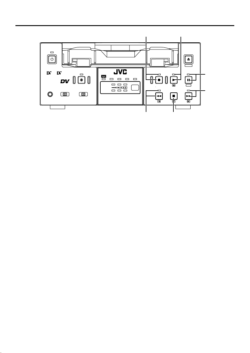
[REC] Record button/LED
8
SERIAL
WIRELESS
A.DUB
INPUT SEL.REMOTE SEL.
DV
LINE
Y/C
● Hold down this button and press the 9 PLAY
button to start recording. During recording, the
LED lights up red.
● Hold down this button and press the 0 PA USE
button to pause the recording.
● When this button is pressed during recording,
an index signal is recorded on the tape (valid
when the INDEX WRITE item in the SYSTEM
menu is set to ON).
● When recording is stopped, the time code generator value can be verified by holding this button down. If the TC DUPLICATE menu item is
set to AUTO or NON DROP, EE signals of the
DV Input time code and Date/Time can be verified.
[PLAY] Play button/LED
9
● Press this button to start playing back a tape.
During playback, the LED lights up green.
● When recording is paused, press this button
to resume recording.
● When the menu is displayed, use this button
to select the menu items or setting values.
[PAUSE] Pause button/LED
0
●
During recording, press this button to pause it.
During playback or STOP mode, press this
button to enter the STILL mode. When recording is paused or when the unit is in the STILL
mode, the LED lights up green.
● If this button is pressed simultaneously with
the A.DUB button in the STILL mode, the Audio Dubbing Pause mode will be engaged.
● When the menu is displayed, use this button
to confirm the menu items or setting values.
[FF] Fast forward button/LED
!
CH-1/3
CH-2/4
DVCAM NTSC
BR-DV3000
EJECT
MENIU
PAL
REC INH.
REC PLAY
REW
STOP
PAUSE
SET
FF
0
!
#@
● When the unit is in the STOP mode, press
this button to execute fast-forward winding of
the tape.
● When the unit is in the PLAYBACK or STILL
mode, press this button to execute fast-forward playback. The Fast-forward playback
speed changes in the following sequence each
time this button is pressed:
X20¥X5¥X10¥X20...
In the DVCAM mode, the maximum speed is 15X.
● During fast-forward winding or fast-forward
playback, the LED lights up green.
● When the menu is displayed, use this button
to display selected menu items.
When setting up the date, time or time code,
use this button to select the data segment.
[STOP] Stop button/LED
@
● Press this button to stop operation. (of rewind,
playback, etc.)
● When the menu is displayed, use this button
to select the menu items or setting values.
[REW] Rewind button/LED
#
● When the unit is in the STOP mode, press
this button to rewind the tape.
● When the unit is in the PLAYBACK or STILL
mode, press this button to execute reverse
playback. The Reverse playback speed
changes in the following sequence each time
this button is pressed:
X20¥X5¥X10¥X20...
In the DVCAM mode, the maximum speed is 15X.
● During rewinding or reverse playback, the LED
lights up green.
● When the menu is displayed, press this button to return to the previous screen.
When setting up the date, time or time code,
use this button to select the data segment.
E-12
Page 13
% $ ^
OPERATE
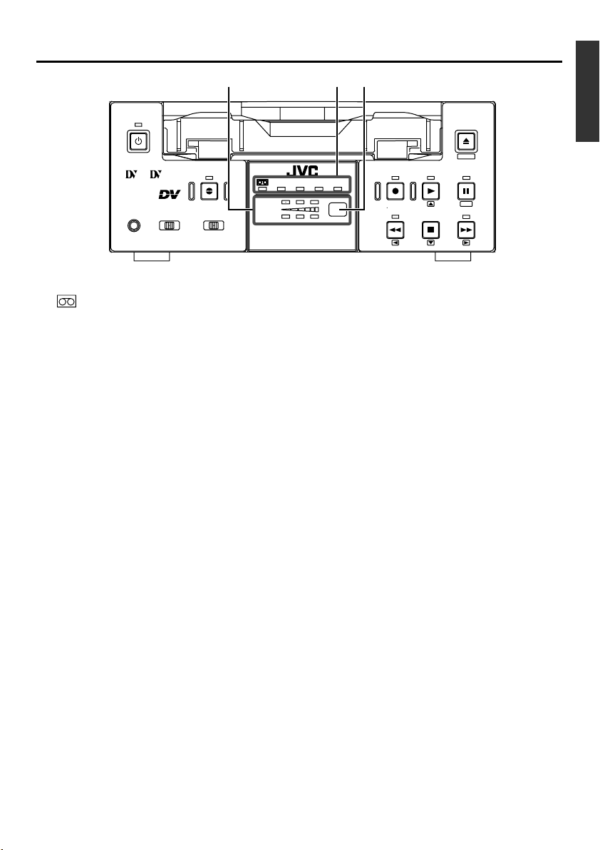
Indicator
$
Mini
PROFESSIONAL
MIC
9PIN
SERIAL
WIRELESS
A.DUB
INPUT SEL.REMOTE SEL.
DV
LINE
Y/C
: When a cassette is loaded, the LED
lights up green. (Likewise when the
unit is in the OPERATE OFF state.)
When a cassette is being loaded
or ejected, the LED blinks.
DVCAM : When the unit plays back a tape re-
corded in the DVCAM format, the
LED lights up green.
NTSC : The LED lights up green in the fol-
lowing cases:
• In the composite video or YC video
signal input mode and the
NTSC/PAL switch located at the
rear panel (☞ Page 14) is set as
“NTSC”.
• A tape recorded with NTSC signals is played back.
• When NTSC system DV signals
are input while the INPUT SEL.
switch is set at “DV”.
PAL : The LED lights up green in the fol-
lowing cases:
• In the composite video or YC video
signal input mode and the
NTSC/PAL switch located at the
rear panel is set as “PAL”.
• A tape recorded with PAL signals
is played back.
• When PAL system DV signals are
input while the INPUT SEL. switch
is set at “DV”.
REC INH : The LED lights up red for about 5
seconds when the unit is set to the
recording mode but fails to record.
E.g. when the rear slide of the cassette is pushed to the “SAVE” position.
CH-1/3
CH-2/4
DVCAM NTSC
BR-DV3000
2
2
EJECT
MENIU
PAL
REC INH.
Audio indicator
%
REC PLAY
REW
STOP
PAUSE
SET
FF
This indicator allows the user to check the availability of audio signals.
3 indicators each are available to CH1/3 and
Ch2/4.
Sensor for wireless remote controller
^
When using the provided wireless remote controller, please point it to this sensor.
(☞ Page 25, “Using the wireless remote controller”)
E-13
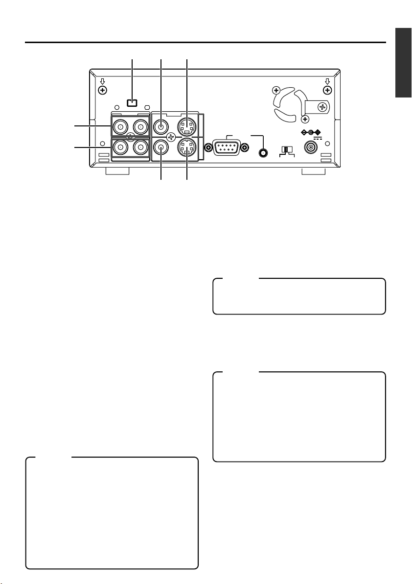
Page 14
NAMES AND FUNCTIONS
OF VARIOUS PARTS
DV IN/OUT
AUDIO VIDEO
CH 1/3 CH 2/4
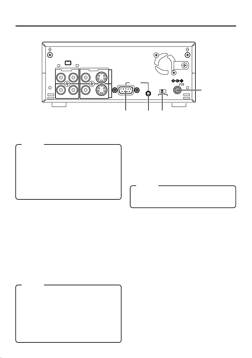
DC power input terminal (2P)
1
This is used for DC12V input. It connects the
DC power cord of the provided AC adapter.
Memo
● When power is supplied to this terminal, the
OPERATE indicator located at the front
panel lights up. (The LED lights up red when
the OPERATE indicator is OFF.)
● Setting this unit to OPERATE ON, OPERATE OFF or PLAY mode when the power is
supplied to this terminal can be done by making the appropriate selections from the DC
IN MODE item in the SYSTEM menu.
[NTSC/PAL] NTSC/PAL signal se-
2
lection switch
Use this switch to select NTSC or PAL as the
signal system. Use it to make a selection when
composite video signals or YC separate video
signals are input.
NTSC : Use this setting for NTSC signal input.
The NTSC indicator on the front panel
lights up.
PAL : Use this setting for PAL signal input.
The PAL indicator on the front panel
lights up.
Memo
● For playback or DV signal input, signals are
determined automatically and not affected
by the status of this switch.
● Please turn the unit to OPERATE OFF before using this switch. If switching is performed when the VTR is in the OPERATE
ON mode, the VTR will automatically go into
the OFF mode before engaging the ON
mode.
● It cannot be used for NTSC/PAL conversion.
E-14
LINE
Y/C
INOUT
– Rear panel –
9PIN
REMOTE
SERIAL
NTSC/PAL
NTSC PAL
DC12V
4 3 2
[SERIAL REMOTE] serial remote
3
terminal (mini jack)
Connect this terminal to the serial remote controller RM-G30, which is available separately.
To control this unit via this terminal, please set
it up as follows.
● Set the REMOTE item of the REMOTE
menu to “ON”.
● Set the REMOTE SEL. switch on the front
panel to “SERIAL”.
Memo
To use this terminal as the FOOT switch input terminal, please set the FOOT SW item
of the REMOTE (2/2) menu. (☞ Page 60)
[9 PIN REMOTE] 9-pin remote ter-
4
minal (D-SUB)
Use this terminal to connect to the RS-422Acompatible editing remote controller (RM-G820).
Please use this unit as a player. To control this
unit with this terminal, please set it up as follows:
● Set the REMOTE item of the REMOTE
menu to “ON”.
● Set the REMOTE SEL. switch on the front
panel to “9 PIN”.
1
Page 15
!65
DV IN/OUT
AUDIO VIDEO
CH 1/3 CH 2/4
LINE
9
0
87
[VIDEO Y/C IN] Video Y/C input
5
terminal (4P)
This is the input terminal for YC separate video signals.
● To input video signals from this terminal,
set the INPUT SEL. switch on the front panel
to “Y/C”.
● When Wide discriminating signals are input, ID signals for Wide discriminating signals are recorded.
[VIDEO LINE IN] Video line input
6
terminal (RCA)
This is the input terminal for composite video
signals.
● To input video signals from this terminal,
set the INPUT SEL. switch on the front panel
to “LINE”.
[VIDEO Y/C OUT] Video Y/C output
7
terminal (4P)
This is the output terminal for YC separate video
signals.
When tapes recorded with Wide discriminating
signals are played, ID signals for discriminating
signals are output.
[VIDEO LINE OUT] Video line out-
8
put terminal (RCA)
This is the output terminal for composite video signals.
Memo
● Besides video signals, the following signals from
the VIDEO Y/C OUT terminal and VIDEO LINE
OUT terminal are displayed on-screen.
• Menu screen signals
• Character display of date, time or operation
modes (Status screen)
By pressing the DISPLAY button on the wireless
remote controller or by setting the DISPLAY item
in the DISPLAY menu, the user can choose to
turn the status display on/off.
● The SETUP item of the AUDIO/VIDEO menu can
be set to determine whether setup will be added
to the signals of VIDEO Y/C OUT terminal and
VIDEO LINE OUT terminal. (NTSC only)
Y/C
INOUT
REMOTE
9PIN
[AUDIO IN] Audio input terminal
9
SERIAL
NTSC/PAL
NTSC PAL
DC12V
(RCA2)
This is the audio signal (analogue) input terminal.
For audio dubbing, sounds from the CH1/3 terminal are recorded on the CH3 channel while
those from the CH2/4 channel are recorded on
the CH4 channel.
Memo
● When the MIC terminal on the front panel is connected to a microphone, sounds from this terminal will not be recorded.
[AUDIO OUT] Audio output terminal
0
(RCA2)
This is the audio signal (analogue) output terminal.
Memo
● The audio channel to play back tapes recorded in
the 32K mode can be selected with the OUT SELECT button on the wireless remote controller or
by setting the AUDIO OUT SEL. item of the AUDIO/VIDEO menu.
● The output level of the playback audio can be selected with the OUT LEVEL button of the wireless
remote controller or by setting the AUDIO OUT
LEVEL item of the AUDIO/VIDEO menu (NORMAL
or ATT).
[DV IN/OUT] DV input/output terminal
!
This is the input/output terminal for digital signals of IEEE1394 standard. It is connected to
video devices with DV terminals.
● To input signals from this terminal, please set
the INPUT SEL. switch on the front panel to
“DV”.
● Signals from this terminal are output regard-
less of the INPUT SEL. switch setting.
E-15
Page 16
NAMES AND FUNCTIONS
OF VARIOUS PARTS
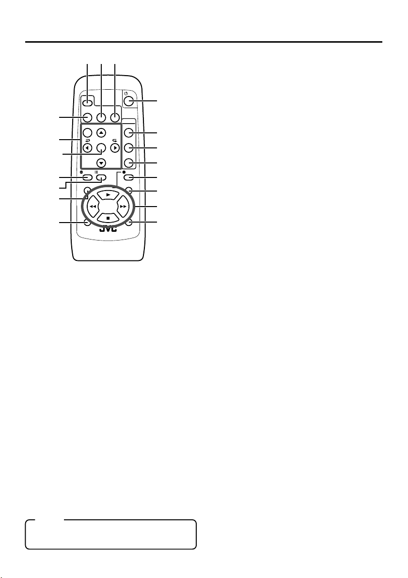
45
2
DISPLAY
STILL
BARS
3
9
SET
button
0
!
$
^
[OPERATE] button f
1
Press this button to turn on the power of the
unit. (OPERATE ON)
Press this button again to turn off the power.
(OPERATE OFF)
[DISPLAY] button
2
Use this button to turn on/off, the on-screen (e.g.
status screen) display on the monitor connected
to the VIDEO LINE OUT terminal and Y/C OUT
terminal. Each time this button is pressed, the
display mode changes in the following sequence: ON (always display) ¥ AUTO (display
when switching mode) ¥ OFF.
(☞ Page 18, “On-screen display”)
[BARS] button
3
When this button is pressed in the Stop or RECPause mode, the color bar of the built in signal
generator will be output. When it is pressed
again, the screen returns to the usual display.
During DV signal input, the color bar will not be
output.
Note
Please do not use it as the standard signal
because the signals are simplified.
MODE
MENU SEARCH+
SET
SEARCH–
A.DUB
PAUSE
F.REV
PLAY
REW FF
STOP
INDEX– INDEX+
REMOTE CONTROL UNIT
RM-G3000
BLANK
AUDIO
MUTING
OUT SEL.
OUT LEV.
REC
F.A DV
1
6
7
8
@
#
&
%
–
Wireless remote controller
[STILL MODE] button
4
Use this button to select images in the STILL
mode.
When the unit is in the STILL mode, press this
button to toggle images in the following sequence.
Field image (1st/2nd alternate still) ¥ 1st field
image ¥ 2nd field image ¥ frame image
[BLANK] button
5
When the unit enters the STOP mode, press
this button to begin a blank search. Once it finds
a blank part of the tape, it will enter the STILL
mode. (☞ Page 47)
[AUDIO MUTING] button
6
During playback, press this button to mute the
audio output. Press this button again to re-enable audio output.
[AUDIO OUT SEL.] button
7
When playing back tapes recorded in the 32K
mode, use this button to select the audio channel that allows output from the AUDIO OUT terminal.
CH1/2 ¥ CH3/4 ¥ MIX
[AUDIO OUT LEV.] button
8
Use this button to switch the standard level
of the playback or EE audio output (NORMAL or ATT). When it is set to ATT, the output level is reduced by 8dB.
Buttons related to menu setting and
9
variable speed playback
[MENU] button
When the unit enters the STOP mode and
this button is pressed, a menu will be displayed on the monitor connected to the
VIDEO LINE OUT or Y/C OUT terminal.
When the menu is displayed, press this button to return to the usual screen display.
[SEARCH+] / button
• During playback, STILL mode or variable
speed playback in the forward direction,
press this button to speed up playback.
• During reverse playback or variable speed
playback in the reverse direction, press this
button to slow down the playback speed.
(☞ page 46)
• When the menu is displayed, use this button to select the menu items or setting values.
–
E-16
Page 17

[SEARCH–] / button
• During playback, STILL mode or variable
speed playback in the forward direction,
press this button to slow down the playback
speed.
• During reverse playback or variable speed
playback in the reverse direction, press this
button to speed up the playback speed.
(☞ page 46)
• When the menu is displayed, use this button to select the menu items or setting values.
[P] / button
• During reverse payback/ variable-speed
playback, press this button to execute forward playback.
• When the menu is displayed, use this button to display the selected menu items.
During date/time or time code setup, press
this button to move the cursor to the right.
[p] / button
• During forward playback/ variable-speed
playback, press this button to execute reverse playback.
• When the menu is displayed, press this
button to display the previous menu.
During date/time or time code setup, press
this button to move the cursor to the left.
SET button
During menu display, press this button to
confirm the menu items or setting values.
[A. DUB] button
0
Press this button to perform audio dubbing (after-recording). (☞ Page 39, “Audio dubbing”)
[PAUSE] button
!
During recording, audio dubbing or playback,
press this button to pause recording or enter
the STILL mode.
If this button is pressed in the STOP mode, the
STILL mode will be engaged.
[REC] button
@
● Hold down this button and press the PLAY
button to begin recording.
● During recording, press this button to record
an index on the tape. (when the INDEX WRITE
item of the SYSTEM menu is set to ON)
● When the unit enters the STOP mode, holding this button down will enable you to check
the value of the time code generator.
[F. ADV] button
#
Each time this button is pressed in the STILL
mode, the image is advanced one frame. When
holding down this button, the image is advanced
continuously frame by frame.
[F. REV] button
$
Each time this button is pressed in the STILL
mode, the image is reversed one frame. When
holding down this button, the image is reversed
continuously frame by frame.
Memo
The image of frame advance playback or frame
reverse playback can be selected with the STL/
F.ADV MODE item of the SYSTEM menu or the
STILL MODE button on the wireless remote controller.
[INDEX+] button
%
Press this button to perform an index search in
the forward direction. (☞ Page 47)
[INDEX–] button
^
Press this button to perform an index search in
the reverse direction. (☞ Page 47)
Operation buttons
&
[PLAY] ( ) button
• Press this button to play back.
• Press this button to resume recording from
the PAUSE mode.
[FF] (
[REW] (
[STOP] ( ) button
• Press this button to fast-forward the tape
when the unit is in the STOP mode.
• Press this button to execute fast-forward
playback in the PLAY or STILL mode.
• Press this button to rewind the tape when
the unit is in the STOP mode.
• Press this button to execute reverse playback in the PLAY or STILL mode.
• Press this button to stop the tape.
) button
) button
E-17
Page 18
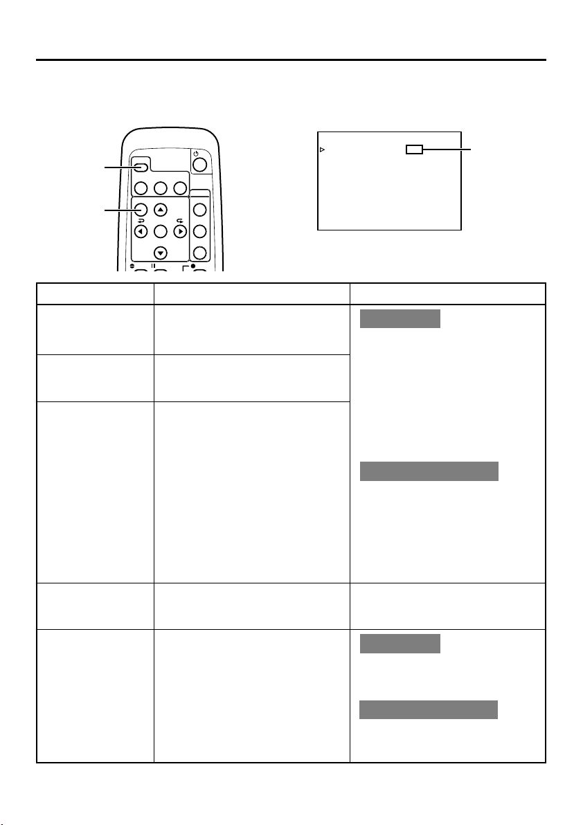
ON-SCREEN DISPLAY
–
Regarding on-screen display
–
Besides E-E images and playback images, the monitor connected to the VIDEO LINE OUT terminal and Y/
C OUT terminal provides the following on-screen information.
Wireless remote controller
DISPLAY
button
MENU
button
DISPLAY
BARS
MENU SEARCH+
A.DUB PA USE
STILL
MODE
SET
SEARCH–
BLANK
AUDIO
MUTING
OUT SEL.
OUT LEV.
REC
DISPLAY (1/2) menu
–––DISPLAY[1/2]–––
DIPLAY ON
COUNT ER POS I . L O
TIME CODE ON
VTR MODE ON
TAPE REMA IN OFF
TIME DATE DATE+ TM
AUD IO I NFO . CH+RATE
NEXT PAGE
PAGE BACK
W
ER -R
Set at ON
or AUTO
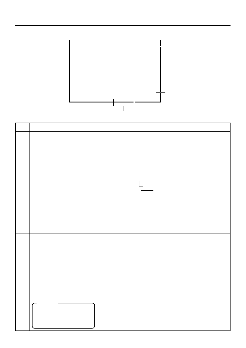
On-screen display Contents Method
Status display
It displays the setting status of date/
time, time code and VTR operation
mode.
Event display
It displays the operating status of the
blank search, index recording/search,
or the wireless remote control.
Alarm display
It displays alarm messages upon operation errors or if the unit is in a poor
state for operation.
Warning display It displays warning messages with er-
ror codes in the event of VTR anomalies. (☞ Page 66)
Menu display It displays the menu setting screen.
(☞ Page 53)
Main unit
Set the DISPLAY item of the DISPLAY
(1/2) menu as follows:
ON : Always display. Depending
on the items, Event and
Alarm displays are shown for
about 3 seconds.
AUTO : It displays for about 4 sec-
onds after switching between
modes.
OFF : No on-screen display.
Remote controller
The display can be turned ON/OFF
with the DISPLAY button. Each time
the DISPLAY button is pressed, the
display mode changes in the following sequence: ON (Always display)
¥AUTO ¥ OFF.
*The settings for the DISPLAY menu
items will also change accordingly.
It is displayed automatically when
anomalies happen.
Main unit
If no cassette is loaded and the EJECT
button is pressed for at least 2 seconds, the menu will be displayed.
Remote controller
If the unit is in the STOP mode and
the MENU button is pressed, the menu
screen will be displayed.
E-18
Page 19
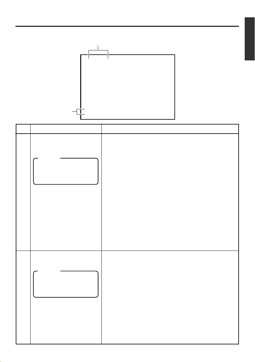
ON-SCREEN DISPLAY
–
Status display
–
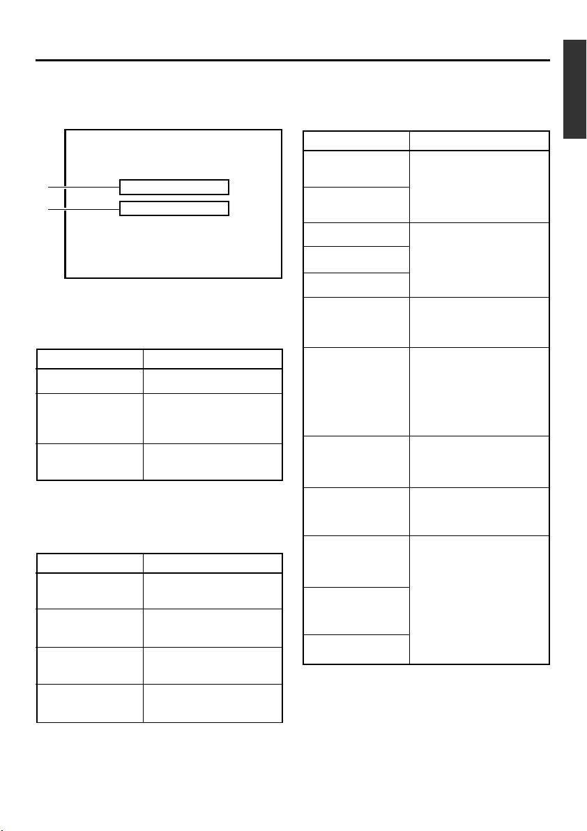
Status display: It displays the current settings and operating status.
1
SP
32K CH–1/2
000
min
2
10/10/ 02 STANDBY-OFF
12:00: 00 TCR 02:00:00:00
No. Item Content
Sampling frequency/audio
1
output CH
Memo
If the time code display position is set to the upper left,
this item will be displayed on
the lower right.
Date/time
2
Memo
If the display position of the
time code is set to the lower
left, this item will be displayed on the lower right.
• Sampling frequency
During recording, the setting value of the AUDIO MODE item
of the AUDIO/VIDEO menu is displayed (32K or 48K).
During playback, the sampling frequency of the sound re-
corded on the tape is displayed (32K, 48K, 44.1K).
During DV signal input, the sampling frequency of the sound
input is displayed.
• A.LOCK
Lights up when the video and audio sampling clocks (at
48kHz) are synchronized in the PLAY mode.
Lights up in the RECORDING mode and EE mode.
Does not light up when the sampling rate is 32kHz or 44.1
kHz.
•Audio output channel
During recording, the audio channel recorded on the tape is
displayed.
During playback, the audio channel output from the AUDIO
OUT terminal is displayed (CH1/2, CH3/4, MIX). (only in 32K
mode)
• The AUDIO INFO. item of the DISPLAY menu can be set to
activate/deactivate the display.
• It displays the date (DD/MM/YY) and time (HR:MM:SS).
• When the unit is in the RECORDING or STOP mode, it displays the data of the built-in clock.
• During playback, fast forward or rewind, the data recorded
on the tape is displayed.
• During DV signal recording, the data from the DV terminal is
displayed. If the REC button is pressed in the STOP mode,
the input data from the DV terminal will be displayed.
• The style for displaying the date and time can be selected
from the DATE STYLE and TIME STYLE items of the DISPLAY menu.
• The TIME/DATE setting of the DISPLAY menu can be set to
turn on/off the date and time display or to select the style.
• When the data/time is not set, “– –” will be displayed.
If a tape with no date and time data is played, "– –" will be
displayed.
E-19
Page 20
ON-SCREEN DISPLAY
32K CH–1/2
–
Status display
SP
min
000
–
(continued)
5
10/10/ 02 STANDBY-OFF
12:00: 00 TCR 02:00:00:00
4
3
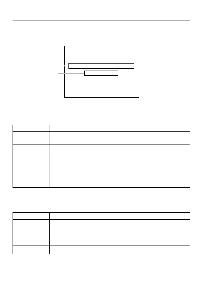
No. Item Content
Time code
3
VTR operation mode
4
• It displays the time codes (hour, minute, second and frame).
During playback, the time codes recorded on the tape are
displayed.
TCR : time code reader data
TCG : time code generator data
DTCG : time code data input from a DV IN terminal
• The symbols for the second and frame differ according to the
framing modes. (NTSC only)
00 : 00 : 00 : 00
dot (.) is used for a dropped frame.
¥
colon (:) is used for a non-dropped
frame.
• The time code display position can be set via the COUNTER
POSI. item of the DISPLAY menu.
• The TIME CODE item can be set to turn on/off the time code
display.
• The user’s bit is not displayed.
It displays the VTR operation modes, including:
PLAY, EJECT, FF, REW, STANDBY-ON, STANDBY-OFF, STILL,
REC, REC PAUSE, A. DUB, A. DUB PAUSE, SHTL (shuttle
search), JOG (F.ADV, R.ADV), BLANK SRH (blank search),
NO CASSETTE (cassette not loaded), OPERATE OFF.
When SHTL or JOG is displayed, the speed will also be displayed at the same time.
• The VTR MODE item of the DISPLAY menu can be set to
turn on/off the VTR operation mode display.
5
E-20
Remaining tape
Memo
If the display position of the
time code is set to the upper
right, this item will be displayed on the lower right.
It displays the remaining tape duration (minutes).
If it is not identified, “ – – – ” is displayed.
• The TAPE REMAIN item in the DISPLAY menu can be set to
turn on/off the remaining tape duration display.
• The SP display disappears when the DVCAM cassette is
being played back.
• Please use the remaining tape time as a gauge.
Page 21
ON-SCREEN DISPLAY
–
Event display
–
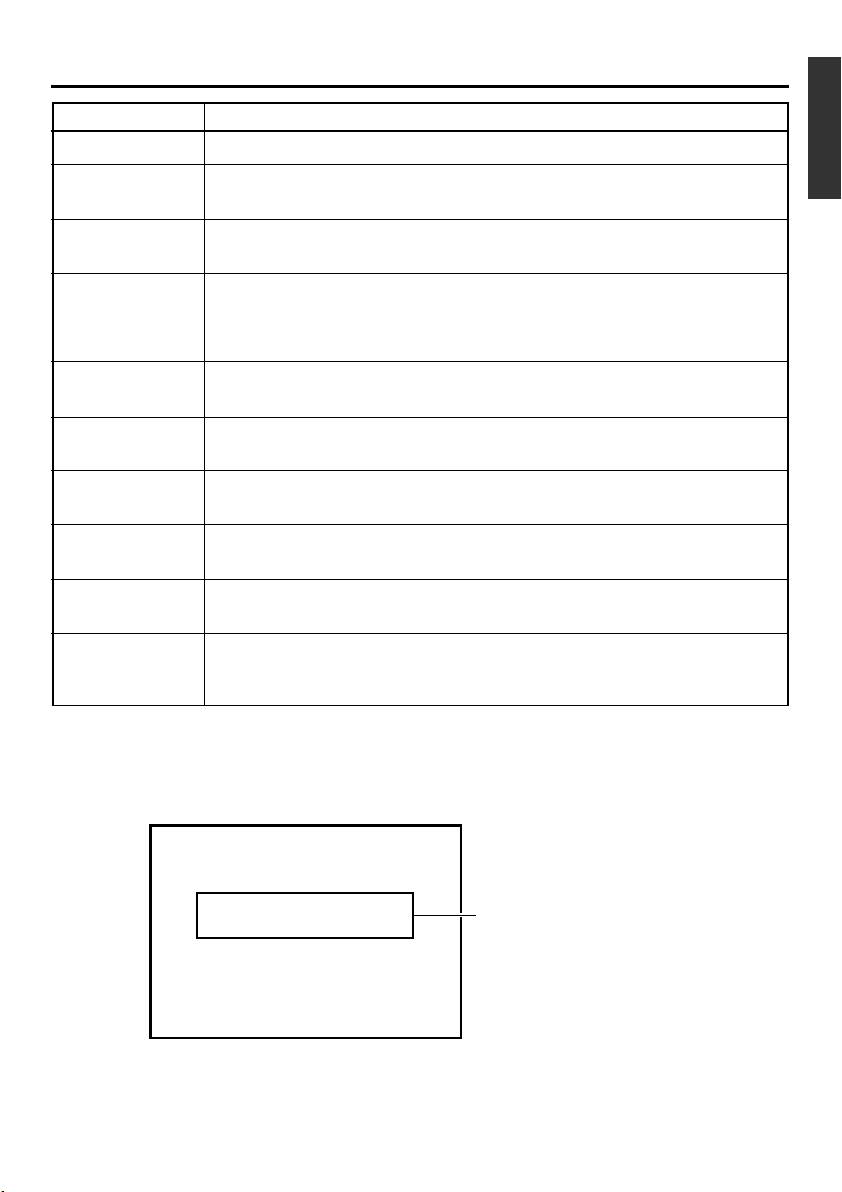
Event display : When a specific function is in activation or when the operation status is
changed with the remote controller, etc, the events will be displayed at
the positions shown below.
32K CH–1/2
A
B
10/10/ 02 STANDBY
12:00: 00 TCR 02:00:00:00
BLANK SEARCH
INDEX DETECTED
Display at position A
...Operation in progress
Display Contents
BLANK SEARCH
INDEX + 1
INDEX MARK
Blank search in progress.
Index search in progress.
The number indicates the
index search position.
When an index is written on
the tape during recording.
SP
000
-
min
OFF
Display Contents
AUDIO OUT
LEVEL NORM
AUDIO OUT
LEVEL ATT
AUDIO OUT CH-1/2
AUDIO OUT CH-3/4
AUDIO OUT MIX
DISPLAY ON
DISPLAY AUTO
DISPLAY OFF
The standard level of the
playback or EE audio level is
set to NORMAL or ATT with
the remote controller.
The playback audio channel is
set to CH1/2, CH3/4 or MIX
with the remote controller.
The on-screen display is
turned on with the remote
controller.
The on-screen display is set
to AUTO with the remote
controller. In the AUTO
mode, the on-screen display
is shown for about 4 seconds
between mode switches.
The on-screen display is set
to OFF with the remote controller.
Display at position B
...Display for about 3 seconds
Display Contents
INDEX DETECTED
VIDEO END
DETECTED
AUDIO MUTING
ON
AUDIO MUTING
OFF
Index is found during an index repeat operation.
Video end is found during a
video end repeat operation.
Audio is muted with the remote controller.
Audio is de-muted with the
remote controller.
FIELD STEP
1ST FIELD STILL
2ND FIELD STILL
FRAME STILL
Field by field advance playback is selected with the remote controller.
When still or frame advance
playback is selected with the
remote controller, the type of
still image is displayed.
• 1st FIELD STILL
• 2nd FIELD STILL
• FRAME STILL
E-21
Page 22
ON-SCREEN DISPLAY
–
Alarm display
–
Alarm display : Alarm messages are displayed as shown below, when an operation
error has occurred or when the unit is in a poor condition for operation.
E.g., dirty head.
SP
32K CH–1/2
A
B
HEAD CLEANING REQUIRED!
NO DV S I GNAL
1 0/10/02 STANDBY
12:00: 00 TCR 02:00:00:00
000
-
min
OFF
Display at position A : Displays which show the state of the unit (and which are not set
via the DISPLAY mode) continues to be displayed here until the
conditions are rectified.
Display Contents
LOW VOLTAGE
HEAD CLEANING
REQUIRED!
The voltage of the DC input power is low. Continued operation will bring the unit to the
Operate OFF mode.
The video head is dirty. Please clean it with the dedicated head-cleaning tape.
(☞ Page 8)
If the head is clogged, it will be detected in the PLAYBACK mode and displayed.
When the unit enters the STOP mode or the cassette is ejected, the display goes off.
OVERHEATING!
The temperature inside the unit has exceeded the regulated value.
Please disconnect the power and place the unit in a cool place.
If this message is displayed again, damage may have occurred. Please consult with
your JVC-authorized service agent.
Display at position B : Messages indicating operation errors are displayed for about 3
seconds.
They are displayed when the DISPLAY mode is ON or AUTO.
Display Contents
INVALID TAPE!
LP TAPE!
NO DV SIGNAL
E-22
Data tapes for PC use or DVC PRO tapes has been inserted.
The cassette will be ejected.
The user attempts to play back a tape recorded in the LP mode.
This unit cannot record or play in the LP mode.
The user attempts to record without DV signal input.
Page 23
Display Contents
COPY INHIBIT
The user attempts to record signals protected with the copy guard.
REC INHIBIT
A. DUB INHIBIT
(REC TAB)
A. DUB INHIBIT
(48K)
A. DUB INHIBIT
(LP)
A. DUB INHIBIT
(BLANK)
A. DUB INHIBIT
(DV)
A. DUB INHIBIT
(NTSC/PAL)
A. DUB INHIBIT
(DVCAM)
OPERATION
LOCK
The user attempts to record on a write protected cassette tape.
(The rear slide is pushed to “SAVE”.)
The user attempts to perform audio dubbing on a write protected cassette tape.
(The rear slide is pushed to “SAVE”.)
This message is displayed when audio dubbing is attempted under the following conditions:
• The AUDIO MODE item of the AUDIO/VIDEO menu is set to 48K.
• The tape is recorded with a sample frequency of 48kHz.
The user attempts to perform audio dubbing on a tape recorded in the LP mode.
The user attempts to perform audio dubbing on a blank tape.
The user attempts to perform audio dubbing during DV signal input. (The INPUT SEL.
switch is set to “DV”)
This message is displayed when the signal system is changed during audio dubbing
(NTSC or PAL).
The user attempts to perform audio dubbing on a DVCAM format tape.
This message is displayed when a button on the unit is pressed while the OPERATION LOCK function is engaged (ie, the OPERATION item of the SYSTEM (2/2) menu
is set as “ON”).
Warning display : When anomalies occur in the VTR, warning messages with error
codes will be displayed.
SP
32K CH–1/2
W
ARNING 7001
DRUM MOTOR FA I LURE
10/10/ 02 STANDBY
12:00: 00 TCR 02:00:00:00
000
-
min
Warning display
For details, please
refer to page 66,
“Warning Display”.
OFF
E-23
Page 24
PREPARATION
–
Provided wireless remote controller
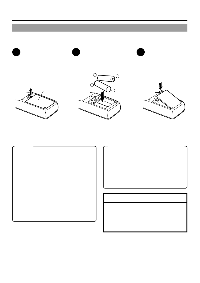
Loading the batteries
Before using the wireless remote controller, please load 2 batteries (AA/R6) in.
–
1
Lift up the cover
of the battery
compartment.
Battery
compartment
cover
2
Load in 2 batteries
(AA/R6).
• Please insert the · pole
Memo
Guide on battery replacement.
When the operable distance of the remote
controller is decreased, the batteries have
become exhausted. Please replace them.
Guide for replacement: Approx 3 months
based on average usage of 1000 times a day.
When replacing the batteries
• Please use AA/R6 batteries.
• Please use 2 new batteries.
(Do not mix new and old batteries.)
• Please load the batteries correctly according to the ª and · signs.
• Please read the precautions printed on the
batteries.
in first.
+
3
Close the cover.
-
+
-
Precautions on the use of battery
• The provided batteries are for confirmation
of operation.
• If the remote controller is not to be used for
a long period of time, please remove the
batteries from the compartment.
• If the remote controller does not work as
expected, please remove the batteries and
reload them after 5 minutes.
Note
If fluid leaks from the battery, please wipe the
battery compartment thoroughly.
If the fluid comes into contact with your body,
please rinse the affected parts with water thoroughly.
E-24
Page 25
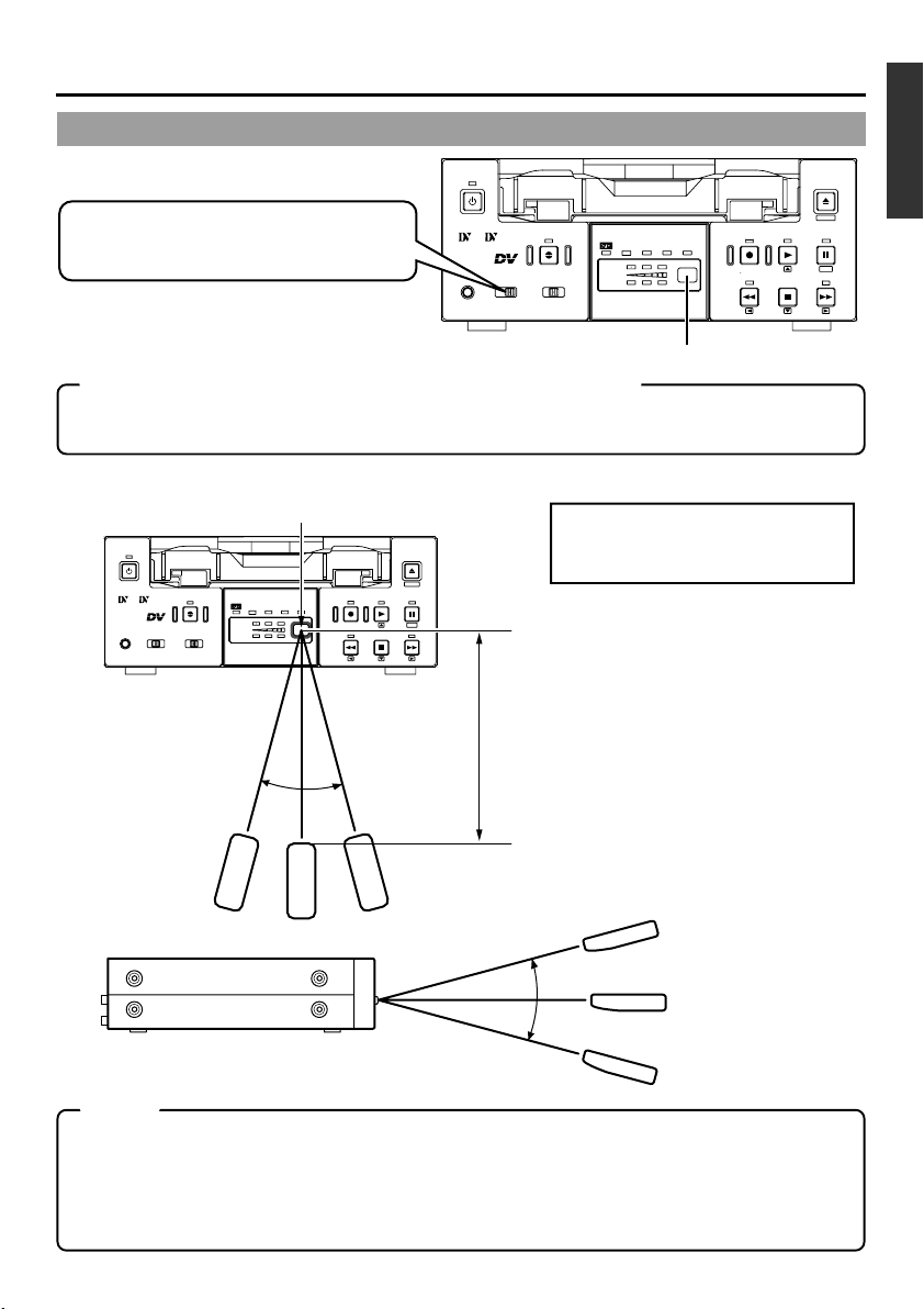
Using the wireless remote controller
OPERATE
Before using the wireless remote controller,
please set the REMOTE SEL. switch to
“WIRELESS”.
Mini
PROFESSIONAL
MIC
A.DUB
INPUT SEL.REMOTE SEL.
LINE
SERIAL
Y/C
DV
9PIN
WIRELESS
CH-1/3
CH-2/4
DVCAM NTSC
BR-DV3000
PAL
REC INH.
REC PLAY
REW
Sensor for the wireless remote controller
Caution on using the wireless remote controller
When more than 2 VTRs are being individually operated in the same place, please ensure that the
front panel REMOTE SEL. switches of all VTRs except the one to be manipulated, are NOT set at
“WIRELESS”.
Operable scope of the wireless remote controller
Sensor for the wireless remote controller
OPERATE
Mini
PROFESSIONAL
MIC
A.DUB
INPUT SEL.REMOTE SEL.
LINE
SERIAL
Y/C
DV
9PIN
WIRELESS
CH-1/3
CH-2/4
DVCAM NTSC
BR-DV3000
PAL
REC INH.
REC PLAY
REW
STOP
About 30˚
EJECT
MENIU
PAUSE
SET
FF
Not further than 6m
Maximum distance to the sensor
of the unit : 6m
Angle : within 30˚
EJECT
MENIU
PAUSE
SET
STOP
FF
About 30˚
Notes
• The remote controller will hardly work if there are obstructive objects between the remote control
sensor of the main unit and the remote controller.
• The remote controller will hardly work when sunlight or strong light shines directly on the remote
control sensor of the main unit.
• Do not press the buttons on the main unit and the remote controller simultaneously for this may
cause malfunction.
E-25
Page 26
PREPARATION
– Power –
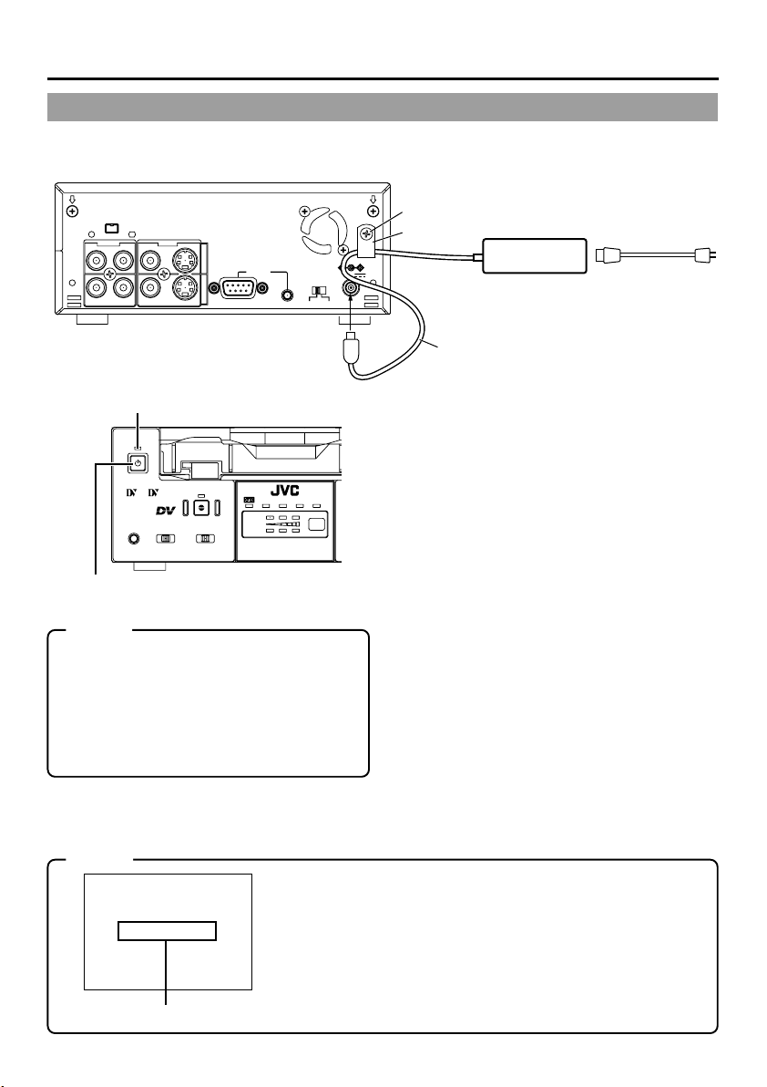
Connecting to the AC adapter
Connect the provided AC adapter to the main unit.
DV IN/OUT
AUDIO VIDEO
CH 1/3 CH 2/4
Y/C
LINE
INOUT
REMOTE
9PIN
SERIAL
NTSC/PAL
NTSC PAL
DC IN terminal
OPERATE indicator
OPERATE
Mini
PROFESSIONAL
A.DUB
INPUT SEL.REMOTE SEL.MIC
LINE
SERIAL
WIRELESS
Y/C
DV
9PIN
CH-1/3
CH-2/4
DVCAM NTSC
BR-DV3000
PAL
REC INH.
OPERATE button
Memo
•Even in the OPERATE OFF mode, a small
amount of electricity will still flow into the unit.
• When the unit is in the OPERATE OFF
mode, no operation can be performed except that of the OPERATE buttons(on the
main unit and the remote controller) and
cassette loading/ejecting.
DC12V
Screw
Clamp
Provided AC adapter
Provided power
cord
DC cord
1.
Connect the DC cord of the AC adapter
to the DC IN terminal of the main unit.
2.
To prevent accidental disconnection of
the DC cord, fasten the DC cord with a
clamp.
1Remove 1 screw followed by the clamp.
2Insert the DC cord into the clamp and fasten
the clamp unto the main unit.
3.
Connect the provided power cord to the
AC IN terminal of the AC adapter.
4.
Connect the power cord to the power
socket.
•Power is channeled into the unit and the OPERATE indicator lights up red.
(OPERATE OFF mode)
• If the DC IN MODE item of the SYSTEM (2/
2) menu is set to “OPE ON” or “PLAY”, the
OPERATE indicator will light up green.
(OPERATE ON mode)
If it is set to PLAY, the VTR will automatically
start to play the loaded tape.
AC
E-26
Notes
LOW VOLTAGE
Alarm message
• Please supply power to the unit via the provided AC adapter. Do
not use other power sources.
• During recording or playback, please do not unplug the DC or
power cord.
• When the supply voltage is low, the “LOW VOLTAGE” alarm message will be displayed. (☞ Page 66)
Page 27
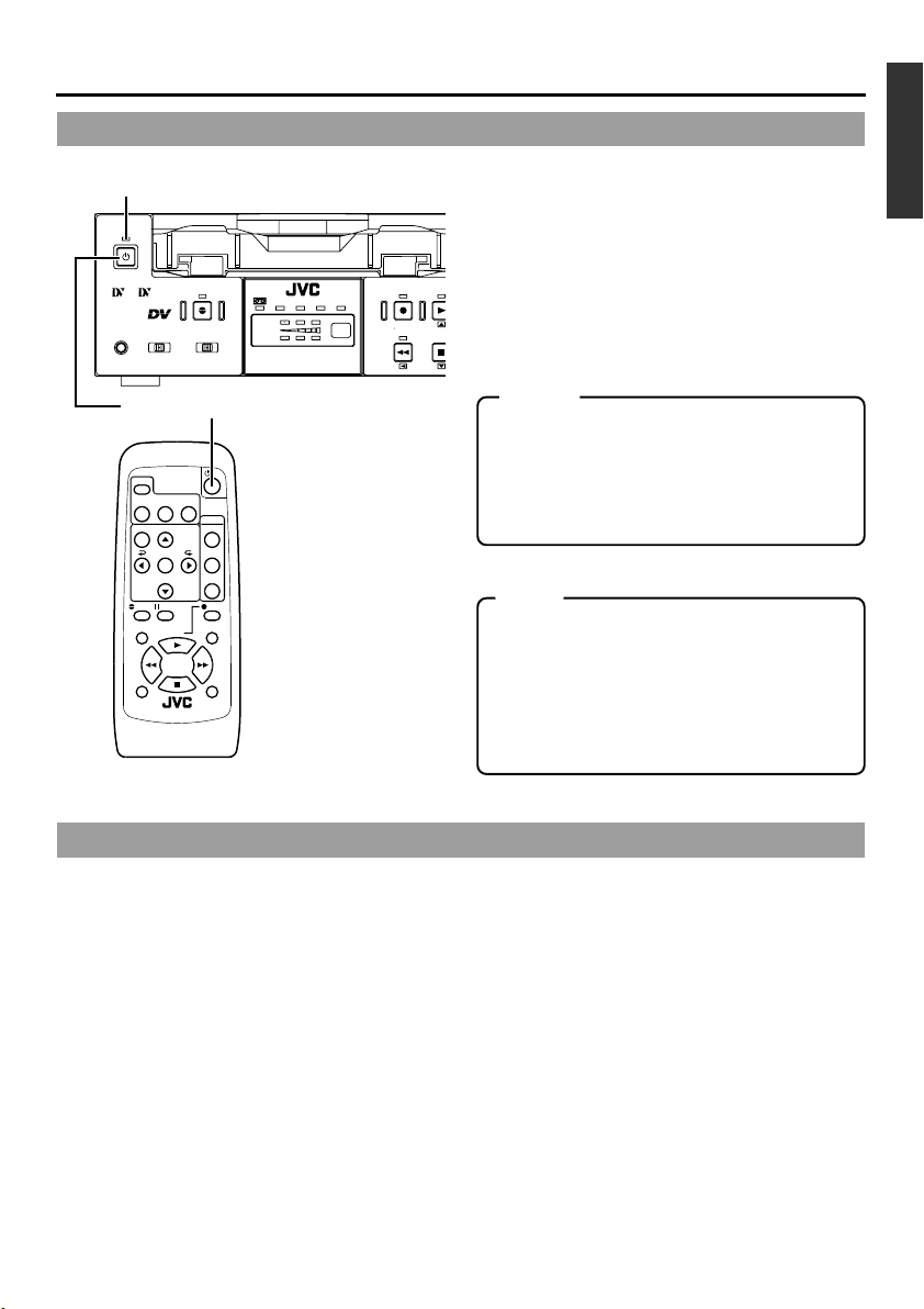
Switching on the power
AY
OPERATE indicator
OPERATE
Mini
PROFESSIONAL
A.DUB
INPUT SEL.REMOTE SEL.MIC
LINE
SERIAL
9PIN
WIRELESS
Y/C
DV
CH-1/3
CH-2/4
DVCAM NTSC
BR-DV3000
PAL
REC INH.
REC PL
REW
When the unit is in the OPERATE OFF
mode (the OPERATE indicator lights
up red), press the OPERATE button on
the unit or the remote controller.
STO
• The power is turned on and the OPERATE indicator lights up green. The unit is now ready
for operation. (OPERATE ON mode)
OPERATE button
Memo
• Once a cassette has been loaded in the OPERATE OFF mode, power will be turned on
DISPLAY
STILL
BLANK
BARS
MODE
AUDIO
SET
SEARCH–
PAUSE
PLAY
STOP
REMOTE CONTROL UNIT
RM-G3000
MUTING
OUT SEL.
OUT LEV.
F.ADV
MENU SEARCH+
A.DUB
F.REV
REW FF
INDEX– INDEX+
REC
and the OPERATE ON mode will be engaged.
• The remote controller is only effective when
the REMOTE SEL. switch is set to “WIRELESS”.
Note
• After pressing the OPERATE button and turning on the power, if the LED blinks in green or
the “UNPLUG MAIN POWER, PLUG BACK
IN AFTER A WHILE” is displayed on the monitor, please unplug the power cord from the
outlet and then wait for some time before plugging it in again.
Turning off the power
Stop all operational activities of the unit.
1.
Press the OPERATE button on the unit or the remote controller.
• The unit will enter the OPERATE OFF mode and the OPERATE indicator will light up red.
2.
If the unit is not to be used for a long period of time, please unplug the AC adapter.
•To disconnect the AC adapter, please unplug the power cord from the socket first.
E-27
Page 28
PREPARATION
–
Selecting the NTSC/PAL signal system
–
This unit supports both the NTSC and PAL signal system.
Before inputting analogue signals (composite or YC separate video signals), please select the
signal system.
A.DUB
INPUT SEL.REMOTE SEL.MIC
LINE
DV
NTSC
indicator
Y/C
CH-1/3
CH-2/4
DVCAM NTSC
BR-DV3000
PAL
REC INH.
PAL
indicator
REC PLAY
REW
NTSC/PAL switch
VIDEO
Y/C
LINE
/4
STOP
INOUT
REMOTE
9PIN
SERIAL
NTSC/PAL
NTSC PAL
DC12V
OPERATE
button
OPERATE
PROFESSIONAL
Mini
SERIAL
9PIN
WIRELESS
Steps
1.
Set the unit to the OPERATE OFF mode.
2.
Please select the signal system with the NTSC/PAL switch on the rear panel.
3.
Press the OPERATE button to engage the OPERATE ON mode. Either the NTSC or
PAL indicator on the front will then light up, according to the NTSC/PAL switch setting.
Memo
• In the playback mode, the signal system of the tape is automatically identified, regardless of the
NTSC/PAL switch setting.
• During DV signal input, the signal system of the input signal is automatically identified, regardless
of the NTSC/PAL switch setting.
• This unit is equipped with a function to automatically detect the signal system of the cassette being
played back or the signal being received at the DV input connector. However, this function may not
operate correctly in some instances.
To ensure the correct system selection, it is recommended that you match the rear panel’s NTSC/
PAL switch to the signal system of the input signal or playback tape.
• When the unit enters the STOP mode, the NTSC/PAL switch setting will be engaged.
• If a tape recorded in both NTSC & PAL signal systems is played, the video, audio or time code may
be distorted at the position where the signal system is switched.
• When the signal system of the tape and the NTSC/PAL setting differ, video and sound output will be
upset for about 5 seconds after playback starts or stops.
• NTSC/PAL signal system conversion is not possible.
E-28
Page 29

PREPARATION
– OPERATION LOCK mode –
This unit comes with an operation lock function to prevent unintended, erroneous operation.
In the OPERATE LOCK mode, the buttons on the main unit and the slide switch are invalid.
However, OPERATE ON and MENU operations are still possible.
SYSTEM (2/2) menu
–––SYSTEM[2 /2 ]–––
DC I N MODE OPE OF F
OPERAT ION LOCK ON
PAGE BACK
–––SYSTEM[2 /2 ]–––
DC I N MODE OPE OF F
OPERAT ION LOCK ON
PAGE BACK
OPERATION LOCK
To set the unit to the OPERATION LOCK mode:
Set the OPERATION LOCK item of the SYSTEM (2/2) menu to
“ON”. (☞ Page 54, “Setting the Menu”)
● In the OPERATION LOCK mode, when a button on the unit is
pressed, “OPERATION LOCK” will be displayed on the monitor
for about 3 seconds.
To turn off the OPERATION LOCK mode:
Set the OPERATE LOCK item of the SYSTEM(2/2) menu to “OFF”.
If the EJECT button is pressed while the VTR is in the OPERATE
LOCK mode, "OPERATION LOCK" will be displayed. However,
pressing the EJECT mode button persistently will eventually bring
on the MENU screen.
E-29
Page 30
PREPARATION
–
Loading/ejecting cassettes
Please use standard DV cassettes or mini DV cassettes.
–
Guide
Standard DV cassettes
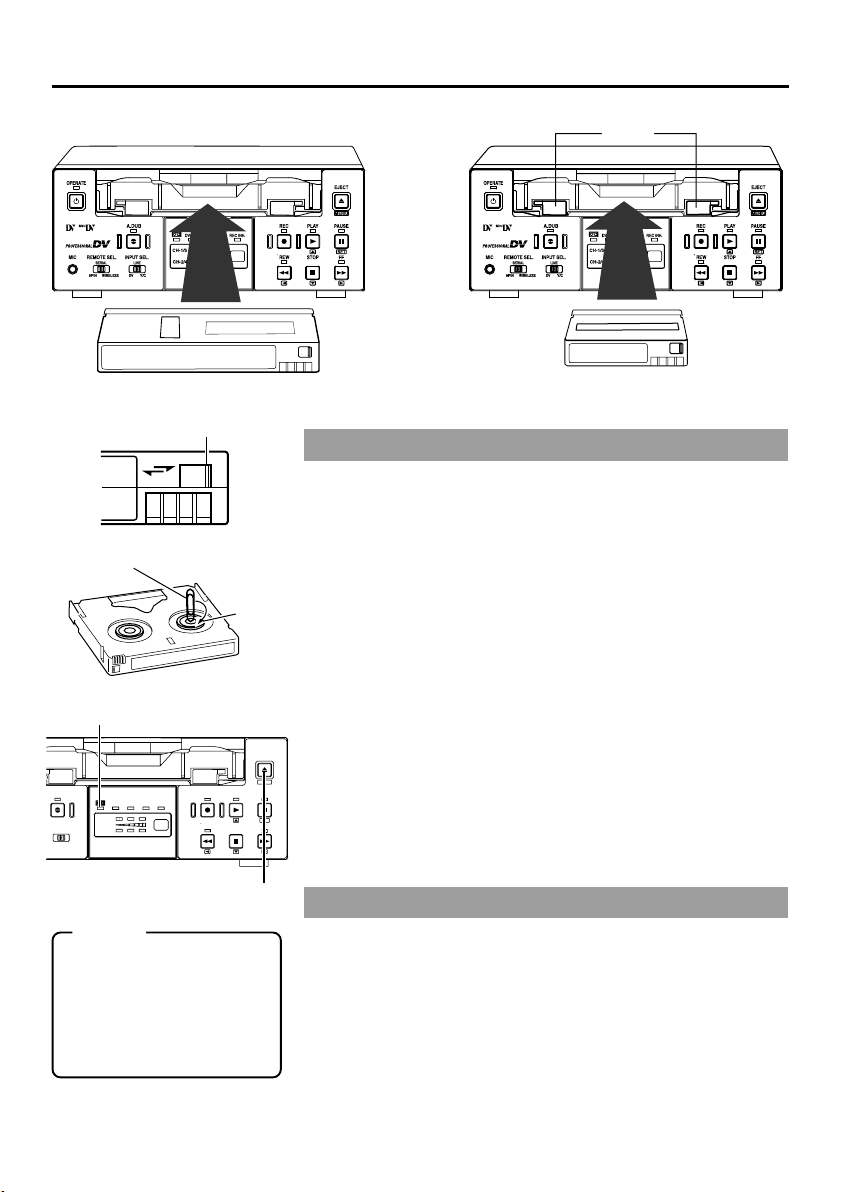
Slide
REC
SAVE
Clip
Cassette indicator
A.DUB
INPUT SEL.
LINE
DV
Y/C
CH-1/3
CH-2/4
DVCAM NTSC
BR-DV3000
PAL
REC INH.
Memo
• The cassette can be loaded/
ejected even when the unit is
in the OPERATE OFF mode.
• The loading/ejection process
takes about 6 seconds.
• Ejection cannot be done with
the wireless remote controller.
Reel
EJECT
MENIU
REC PLAY
PAUSE
SET
REW
STOP
FF
EJECT button
Mini DV cassettes
Loading the cassette
1.
Check the cassette.
• Set the rear slide.
Push it to “REC” for recording or “SAVE” to prevent its contents
from being erased accidentally.
• Check that the tape is not slackened.
Use an object, such as a clip, to turn the reel in the direction of
the arrow. If the tape is taut, the reel will not rotate.
2.
Check that the cassette indicator on the unit is unlit.
When a cassette is loaded, the cassette indicator will lit up.
3.
Load the cassette.
•For the standard DV cassette, just align it with the cassette slot
and insert.
•
For the mini DV cassette, load it in between the left and right guides.
Set the tape, window face up, and push the cassette in slowly
until it is drawn in automatically.
¥
While the cassette is being loaded, the cassette indicator blinks.
The indicator lights up when cassette loading is complete.
Ejecting the cassette
1.
Press the EJECT button on the unit.
¥
Ejection begins. During ejection, the cassette indicator blinks.
2.
Eject the cassette.
E-30
Page 31

PREPARATION
–
Setting/displaying date and time
This function sets up the date and time data of the built-in clock. With the built-in chargeable
battery, the configured date and time data is maintained even after the main power is turned
off. The data will be displayed on the monitor according to the menu setting. During tape
recording, the time and date data is registered.
2.
1.
MENU
button
2.
– 2 SET
button
DISPLAY
BARS
MENU SEARCH+
SEARCH–
2.
STILL
MODE
SET
– 1 button
BLANK
AUDIO
MUTING
OUT SEL.
2.
OUT LEV.
– 1 button
– 2 button
CH-1/3
CH-2/4
DVCAM NTSC
BR-DV3000
PAL
REC INH.
REC PLAY
REW
EJECT
1.
2.
1
PLAY/STOP
EJECT button
–
2
PAUSE/FF
button
MENIU
PAUSE
SET
STOP
FF
2.
–
button
Setting the date and time
Top MENU
SYSTEM. .
REMOT E. .
AUD IO / V IDEO . .
TIME CODE . .
DISPLAY SET. .
CLOCK ADJUST . .
FACTORY SETTING CANCEL
DRUM HOURMETER 000000
EX I T
–––MENU–––
CLOCK ADJUST menu
–––CLOCK ADJUST–––
DATE ( DD /MM/ YY) 10/10/02
TIME 00:00:00
PAGE BACK
The date and time data is set up via the CLOCK ADJUST menu.
Setting can be performed while viewing the monitor screen
connected to the VIDEO LINE OUT or Y/C OUT terminal.
• The date and time can be set up using either the remote
controller or the unit.
Press the OPERATE button on the unit or the remote
controller to turn on the power and enter the STOP mode.
* When setting it using the main unit, eject the loaded cassette, if
any.
1.
Displaying the top MENU.
Remote controller
Press the MENU button.
Main unit
Press the EJECT button for at
least 2 seconds.
–
2.
Displaying the CLOCK ADJUST menu.
Remote controller
Press the or button
1
1
and bring the cursor to the
CLOCK ADJUST item.
Press the SET or button.
2
2
Main unit
Press the PLAY or STOP
button and bring the cursor
to the CLOCK ADJUST
item.
Press the PAUSE or FF
button.
E-31
Page 32

PREPARATION
3.
–
13
button
–
Setting/displaying date and time
3.
–
,
4.
13
PLAY button
–
(continued)
,
4.
DISPLAY
STILL
BARS
MODE
MENU SEARCH+
,
4.
SET
SEARCH–
3.
5.
MENU
button
–
2
button
3.
Date (DD/MM/YY)
–––CLOCK ADJUST–––
DATE 10/10/02
TIME 00:00
PAGE BACK
Time
–––CLOCK ADJUST–––
DATE 10/10/02
TIME 12:00
PAGE BACK
BLANK
–
AUDIO
MUTING
OUT SEL.
OUT LEV.
13
button
,
4.
3.
–
SET button
3.
–
button
4
,
4.
PAL
DVCAM NTSC
BR-DV3000
3.
–
REW button
REC INH.
2
CH-1/3
2
3.
Set the date or time on the CLOCK ADJUST menu.
CH-2/4
REC PLAY
REW
,
4.
Remote controller
Press the or button
1
and bring the cursor to the
date or time setting. Then
press the or SET button.
Press the or button
2
and select the data segment to set up.
• The selected data segment blinks.
Press the or to set the
3
value.
Repeat step 1 – 3. After
4
completing the necessary
settings, press the SET
button.
EJECT
MENIU
PAUSE
SET
STOP
FF
3.
–
STOP button
Main unit
Press the PLAY or STOP
1
button and bring the cursor
to the DATE or TIME setting.
Then press the FF or PAUSE
button.
Press the FF or REW but-
2
ton and select the data segment to be set up.
• The selected value blinks.
Press the PLAY or STOP
3
button to set the value.
Repeat step 1 – 3. After
4
completing the necessary
settings, press the PAUSE
button.
Memo
The ‘seconds’ segment cannot be set up. After the ‘minute’ segment is set
up, please press the SET button (remote controller) or the PAUSE button
(main unit) in synchronization with a separate time indicator (clock).
5.
EJECT button
3.
–
PAUSE button
3.
–
FF button
13
,
4.
4
,
4.
2
–––CLOCK ADJUST–––
DATE 10/10/02
TIME 12:00
PAGE BACK
E-32
4.
To return to the top MENU after completing all settings,
do the following:
Remote controller
• Press the button.
Or
• Press the or button to
bring the cursor to PAGE
BACK and then press the
SET button.
5.
To return to the usual menu, do the following:
Remote controller
• Press the MENU button.
Or
•Bring the cursor to the EXIT
item of the top MENU and
press the SET button.
Main unit
• Press the REW button.
Or
• Press the PLAY or STOP button to bring the cursor to
PAGE BACK and then press
the PAUSE button.
Main unit
• Press the EJECT button.
Or
•Bring the cursor to the EXIT
item of the top MENU and
press the PAUSE button.
Page 33

Selecting date/time display
The date and time data is displayed on the monitor screen connected to the VIDEO LINE OUT
terminal and Y/C OUT terminal. Setup can be performed via the DISPLAY (1/2) menu to turn
on/off the date & time display and via the DISPLAY (2/2) menu to determine the display style.
(For details on setup method:
Page 54)
☞
Top MENU display
SYSTEM. .
REMOT E. .
AUD IO / V IDEO . .
TIME CODE . .
DISPLAY SET. .
CLOCK ADJUST . .
FACTORY SETTING CANCEL
DRUM HOURMETER 000000
EX I T
–––MENU–––
DISPLAY (1/2) menu
–––DISPLAY[1/2]–––
DIPLAY OFF
COUNT ER POS I . L O
TIME CODE ON
VTR MODE ON
TAPE REMA IN OFF
TIME DATE DATE+ TM
AUD IO I NFO . CH+RATE
NEXT PAGE
PAGE BACK
W
ER -R
DISPLAY (2/2) menu
–––DISPLAY[2/2]–––
DATE STYLE DD /M M/ YY
TIME STYL E 24H
BARS OFF
PAGE BACK
DISPLAY button
Setting
1.
Select DISPLAY SET item from the top MENU and display the DISPLAY (1/2) menu.
2.
Set the TIME/DATE setting on the DISPLAY (1/2) menu.
TIME DATE
OFF : Does not display date or time.
TIME : Displays time only.
DATE : Displays date only.
DATE + TM : Displays both the time and date.
3.
Select the NEXT PAGE item of the DISPLAY (1/2) menu
to engage the DISPLAY (2/2) menu.
4.
Set the DATE STYLE and TIME STYLE items of the
DISPLAY (2/2) menu.
DATE STYLE... Set the order of the date display.
YY/MM/DD: Year / month / day
MM/DD/YY: Month / day / year
DD/MM/YY: Day / month / year
TIME STYLE...Select the style of time display.
24H: 24-hour time mode
12H: 12-hour time mode
Enabling on-screen display:
DISPLAY
STILL
BARS
BLANK
MODE
AUDIO
MENU SEARCH+
On screen display
32K CH–1/2
10/10 /02 STANDBY–OF F
12:00 :00 TCR 02:00:00:00
Date/time display
MUTING
SP
000
min
Remote controller
• Press the DISPLAY button.
Main unit
• Set the DISPLAY item of the
DISPLAY (1/2) menu to ON
or AUTO.
Memo
• RECORDING or STOP mode : Data in the built-in clock is displayed.
• During Playback : The date/time recorded on the tape is
• During DV signal recording : The date/time data from the DV termi-
displayed.
nal is displayed.
E-33
Page 34

RECORDING
– Connection and setting –
This chapter explains the connection, setting and operation methods required to use this unit
as a recorder.
This unit cannot be used as an editing system recorder.
Connection
When connected to a video device equipped with a DV terminal
Images can be recorded with almost no deterioration of image quality.
9PIN
REMOTE
SERIAL
Recorder
DC12V
NTSC/PAL
NTSC PAL
Monitor
Player
DV terminal
Another VTR
Separately available
DV cable
Flow of
DV IN/OUT
AUDIO VIDEO
CH 1/3 CH 2/4
DV terminal
LINE
Y/C
INOUT
signal
Memo
•Turn the power of both devices OFF and connect the DV cable.
• Do not insert incorrectly (in reverse) the DV cable end to DV port of both devices.
• When signals are input from the DV terminal, the sound recording mode of the recorder is the same
as that of the player.
• The Date and time data from the DV terminal will be recorded.
•To record the time code data from the DV terminal, set the TC DUPLICATE item of the TIME CODE
menu to AUTO or NON DROP. (☞ Page 62)
•For the BR-DV600 player, when the mode is changed from STILL to PLAY, the audio output will be
muted for a while shortly after coming on. Thereafter, it will resume as per normal. (This does not
occur with BR-DV600A.)
• When it is connected to D9VTR (equipped with SA-DV60), exchanging of the date/time information
is not possible.
This unit is connected to a video device with no DV terminal (analogue input):
Y/C(S) video cable
AUDIO
OUT
Video cable
Audio cable
Flow of
signal
AUDIO
DV IN/OUT
CH 1/3 CH 2/4
IN
AUDIO VIDEO
LINE
Y/C
IN
Y/C
Recorder
INOUT
REMOTE
9PIN
SERIAL
NTSC/PAL
NTSC PAL
DC12V
Y/C
OUT
Player
Another VTR
VIDEO OUT VIDEO LINE IN
Monitor
Memo
When search pictures or low-quality video signals are input, video and sound output may be temporarily distorted. Please input stable signals via a TBC, etc.
E-34
Page 35

Setting
NTSC indicator PAL indicator
OPERATE
Mini
PROFESSIONAL
A.DUB
INPUT SEL.REMOTE SEL.MIC
LINE
SERIAL
9PIN
DV
WIRELESS
DVCAM NTSC
CH-1/3
CH-2/4
Y/C
BR-DV3000
INPUT SEL. switch
Memo
• For DV signal input, the sig-
nal system (NTSC/PAL) is
identified automatically.
• For DV signal input, the AU-
DIO MODE item cannot be
set. It will be the same mode
as that of the input signal.
(48K or 32K)
AUDIO/VIDEO menu
–––AUDIO V IDEO–––
AUD IO MODE 4 8K
AOUT ATSEARCH ON
AUD IO OUT SEL CH- 1 / 2
AUD IO OUT LEVEL NORM
SET UP (NTSC ) OFF
PAGE BACK
SYSTEM (1/2) menu
–––SYSTEM[1 /2 ]–––
STL / F.ADV 2ND
BACKUP REC T IME OFF
LONG PAUSE T IME 5MI N
LONG PAUSE MODE F . ADV
INDEX
W
RITE ON
REPEAT MODE BLANK
NEXT PAGE
PAGE BACK
Rear panel
EJECT
PAL
REC INH.
REC PLAY
REW
MENIU
PAUSE
SET
STOP
FF
IO VIDEO
LINE
CH 2/4
Y/C
INOUT
REMOTE
9PIN
SERIAL
NTSC/PAL switch
Setting the signal system (NTSC/PAL)
The signal system for analogue input is set with the NTSC/PAL
switch located at the rear panel. Either the NTSC or the PAL indicator on the front lights up, depending on the setting.
* Before setting the NTSC/PAL switch, please set the unit to the
OPERATE OFF mode.
Selecting the video input signal
Please use the INPUT SEL. switch on the front panel.
Y/C : Input Y/C separate video signals.
LINE: Input composite video signals.
DV : Input DV signals.
Setting the AUDIO/VIDEO menu (☞ Page 61)
• AUDIO MODE
Use this menu item to set the audio sampling frequency for recording.
32K : Perform recording with an audio sampling frequency of 32kHz.
Use this setting when performing audio dubbing on CH3 and
CH4.
48K : Perform recording with an audio sampling frequency of 48kHz.
Audio dubbing is not available.
• SET UP (NTSC only)
Set this item to enable/disable setup to composite signals or Y/C
separate video during recording.
Setting the SYSTEM menu (☞ Page 57)
• LONG PAUSE TIME
Sets the time period, after the lapse of which the unit will enter the
tape protection mode when pause is activated for an extended period of time.
• INDEX WRITE
This setting turns on/off automatic recording of index signals when
recording begins.
Setting the time code recording during DV signal input
Set the TC DUPLICATE item of the TIME CODE menu to determine
whether to use the time code from the built in time code generator
and clock or the data from the DV terminal. (☞ Page 62)
NTSC/PAL
NTSC PAL
DC12V
E-35
Page 36

RECORDING
– Setting time codes –
Time code recording
This unit has a built-in time code reader/ generator. It records time codes during recording. It
does not record the user’s bit.
Time codes are recorded according to the recording condition as follows:
Time codes are recorded in the REC RUN mode. (REC RUN: time codes run only during
recording.)
Condition Time code recording
Time code is preset with this unit.
• Time codes preset in the built-in time code generator are recorded. (First time only)
• When recording ends, the set time codes becomes void and
regeneration occurs.
Memo
The framing mode is selected from the NDF/DF item of the TIME
CODE menu. (NTSC only)
Time code is not preset.
Preset time codes.
button
DISPLAY
STILL
BLANK
BARS
MODE
SET
SEARCH–
AUDIO
MUTING
OUT SEL.
OUT LEV.
MENU
button
button
MENU SEARCH+
button
Memo
When the REC button is held
down in the STOP mode, the
value of the built-in time code
generator is displayed.
SET button
button
• It reads the time codes recorded on the tape and continues
recording time codes from these values. (Regeneration)
• If no time code is recorded, it starts from “00”.
* Sometimes, the time codes recorded at the beginning of the
tape may not be read.
PLAY button
EJECT
EJECT button
PAL
DVCAM NTSC
CH-1/3
EL.
CH-2/4
Y/C
REC INH.
BR-DV3000
REC PLAY
REW
REW button
MENIU
PAUSE
STOP
STOP button
SET
FF
PAUSE button
FF button
Time codes are preset via the TIME CODE menu. It can be
set via either the remote controller or the Main unit.
Press the OPERATE button on the Main unit or the
remote controller to turn on the power and set the
unit to the STOP mode.
*To set it with the main unit, first remove the cassette from the
unit if it is loaded.
E-36
Page 37

Top MENU
SYSTEM. .
REMOT E. .
AUD IO / V IDEO . .
TIME CODE . .
DISPLAY SET. .
CLOCK ADJUST . .
FACTORY SETTING CANCEL
DRUM HOURMETER 000000
EX I T
Time Code
TC 0 0:00:00:00
CLEAR CANCEL
NDF /D F(NT SC ) DROP
TC DUPL I CATE OFF
TC AD JUST( DV) OFF
PAGE BACK
–––MENU–––
TIME CODE menu
–––TIME CODE–––
Minute Frame
Hour Second
Framing mode
(NTSC only)
Resetting the time code
to zero:
Select the CLEAR menu
1
item.
Set the value to EXECUTE
2
and press the SET button
(remote controller) or the
PAUSE button (Main unit).
Memo
Framing mode (NTSC only)
DROP
:Time codes that
match the actual
time.
NON DROP
: Use this setting if the
number of frames is
important.
1.
Display the top MENU.
Remote controller
Press the MENU button.
2.
Display the TIME CODE menu.
Remote controller
Select the TIME CODE item
with the / button and
press the SET or button.
3.
Preset the time code (hour, minute, second and frame).
Remote controller
Select the TC item with the
1
/
button and press the
SET or button.
¥ The hour digits blink.
Press the / button to
2
shift to the next digit segment.
Press the / button to
3
change the value of the
blinking digits.
Repeat steps 2 and
4
above and set all the values. Press the SET button.
4.
Set the framing mode (NON DROP / DROP) ... (NTSC only)
Remote controller
Select the NDF/DF item
1
with the / button and
press the SET or button.
Press the / button to
2
select the value.
Press the SET button to
3
confirm the setting value.
5.
Return to the usual screen.
Remote controller
Press the MENU button.
3
Main unit
Press the EJECT button for at
least 2 seconds.
Main unit
Select the TIME CODE item
with the PLAY/STOP button
and press the PAUSE or FF
button.
Main unit
Select the TIME CODE item
1
with the PLAY/STOP button
and press the PAUSE or FF
button.
Press the FF or REW but-
2
ton to shift to the next digit
segment.
Press the PLAY/STOP but-
3
ton to change the value of
the blinking digits.
Repeat 2 and 3 steps
4
above and set all the values.
Press the PAUSE button.
Main unit
Select the NDF/DF item with
1
the PLAY/STOP button and
press the SET or FF button.
Press the PLAY/STOP but-
2
ton to select the value.
Press the PAUSE button to
3
confirm the setting.
Main unit
Press the EJECT button.
Recording time codes of a DV input terminal:
• Set the TC DUPLICATE item of the TIME CODE menu to AUTO.
•To record time codes in the non-drop frame mode from BR-DV600, GY-DV500 or GY-DV700W,
set the TC DUPLICATE setting to NON DROP.
Memo
If the REC button is held down in the STOP mode when the TC DUPLICATE item is set to AUTO or NON DROP,
the EE signals of the time codes from the DV input terminal can be checked.
E-37
Page 38

RECORDING
– Recording method –
Remote controller
2.
3.
PAUSE
F.REV
PLAY
STOP
REMOTE CONTROL UNIT
RM-G3000
REC button
REC
F.AD V
PAUSE button
2. 4.
PLAY
button
5.
STOP
button
A.DUB
REW FF
INDEX– INDEX+
Memo
• If recording has been
paused for an extended
period of time, the unit
will automatically go into
the STOP mode to protect the tape. The time
period after the lapse of
which the unit will enter
the STOP mode can be
configured via the LONG
PAUSE TIME item of the
SYSTEM (1/2) menu.
• This unit cannot perform
editing functions.
Main unit
2. 4.
2.
PLAY
REC
button
button
OPERATE
Mini
PROFESSIONAL
SERIAL
9PIN
1.
Load the cassette.
WIRELESS
INPUT SEL.REMOTE SEL.MIC
A.DUB
DV
REC INH.
REC PLAY
REW
PAL
DVCAM NTSC
CH-1/3
CH-2/4
LINE
Y/C
BR-DV3000
EJECT
MENIU
PAUSE
SET
STOP
FF
5.
STOP button
• Before loading the cassette, please check that the rear slide of
the cassette is pushed to REC.
¥ The Main unit is powered on.
2.
Start recording.
• Hold down the REC button and press the PLAY button.
3.
Pause recording.
• Press the PAUSE button.
4.
Resume recording.
• Press the PLAY button.
5.
Stop recording.
• Press the STOP button.
3.
PAUSE
button
Memo
If recording is executed
right after the RECORDING PAUSE state, index
signals will not be recorded.
E-38
Recording index signals
When the INDEX WRITE item of the SYSTEM (1/2) menu is
set as ON, an index signal is recorded at the starting position
of recording.
In the PLAYBACK mode, the position where the index signal is
recorded can be detected. (Index search)
During recording, please press the REC button to record
the index signal.
* Please allow at least an interval of 1 minute between recording of
index signals.
Recording of index signals after tape recording is not possible.
Page 39

RECORDING
– Audio dubbing –
For tapes recorded in the 32kHz audio mode, audio dubbing can be performed on the CH3 and
CH4 channel after the recording. (After-recording)
Notes
• For tapes recorded in the 48kHz audio mode, audio dubbing cannot be performed.
• Audio dubbing cannot be performed for DV input signals.
3.
A.DUB
button
1. 4.
PLAY
button
5.
STOP
button
2. 3.
PAUSE button
A.DUB
PAUSE
F.REV
PLAY
REW FF
STOP
INDEX– INDEX+
REMOTE CONTROL UNIT
RM-G3000
3.
A.DUB button
REC
F.AD V
OPERATE
Mini
PROFESSIONAL
9PIN
MIC
terminal
SERIAL
WIRELESS
INPUT SEL.REMOTE SEL.MIC
A.DUB
DV
PAL
DVCAM NTSC
CH-1/3
CH-2/4
LINE
Y/C
REC INH.
BR-DV3000
1. 4.
PLAY button
REC PLAY
REW
STOP
5.
EJECT
MENIU
PAUSE
2. 3.
SET
PAUSE
FF
button
STOP buttonINPUT SEL. switch
Memo
Connection
Audio dubbing sounds are input from the AUDIO IN
terminal on the rear panel or the MIC terminal on
the front panel. MIC terminal prevail over the AUDIO IN terminal.
Setting
• Set the AUDIO item of the AUDIO/VIDEO menu
to “32K”.
• Do not set the INPUT SEL. switch on the front
panel to “DV”.
Operation
1.
Press the PLAY button to play the tape.
2.
At the position where you want to audio dub, press the PAUSE button.
¥ The unit goes into the STILL mode.
3.
Hold down the PAUSE button and press
the A.DUB button.
¥ The unit goes into the audio dubbing pause
mode.
4.
Press the PLAY button.
¥ Audio dubbing begins. Audio signals are
recorded on the CH3 and CH4 channel.
To stop audio dubbing temporarily, press
the PAUSE button.
5.
To end audio dubbing, press the STOP
button.
• During audio dubbing, if the tape comes to a
part recorded in a non dubbing-feasible mode
(such as LP mode or 48kHz audio mode), the
VTR will enter the STOP mode. When this happens, high-volume noise from the DV output
will occur. Hence, before audio-dubbing,
please check the recording mode of the tape.
• In the case that a microphone is connected to
the MIC terminal, sound output from this terminal will be recorded. In the absence of MIC
input, signals from the CH1/3, CH2/4 AUDIO
IN terminal on the rear panel will be recorded.
• When audio dubbing cannot be performed, an
alarm message will be displayed on the monitor. ( ☞ Page 23)
• Audio dubbing PAUSE cannot be executed directly in the STOP mode. Please execute it in
the STILL mode.
During audio dubbing pause, sound from the
CH3/CH4 channel is output via the monitor
but sound output from the DV terminal is not
possible.
• If audio dubbing is repeated on a short section of the tape, noise may occur for an instant when the section is played.
• During audio dubbing, noise may be produced
on the playback video or EE sound but the
recording is normal.
• The playback sound of CH1/2 cannot be recorded on CH3/4 (sound on sound).
• During backspace operation of audio dubbing,
audio dubbing cannot be performed on unrecorded parts.
• When audio dubbing is performed on tapes
recorded on other devices, it may not record
correctly. Please record with this unit before
performing audio dubbing.
E-39
Page 40

RECORDING
– Backup recording function –
By linking this unit to other DV devices, this unit can perform continuous, long-hour recording.
This unit can be set as a backup unit connected to a DV camcorder (GY-DV300/DV500/DV550/
DV5000, etc.). When the recording tape of the source unit ends, this unit can start recording.
This enables long-hour recording.
Backup unit: the main unit
FILTER
1 3200k
2 5600k
3 5600k+ND
STATUSSHUTTER
MENU
AUTO IRIS LOLUX
FULL AUTO BLACK
BACK L
NORMAL
SPOT L
Y
B
T
S
E
V
A
S
VTR
NG
OPERATE
OPERATE/WARNING
LIGHT
ON
RESET
OFF
MONITOR
COUNTER
SELECT
CTL
ALARM
TC
UB
MONITOR
CH-2
CH-1
AUDIO
LEVEL
STRETCH
NORMAL
COMPRESS
E
B
N
E
M
A
O
N
A
T
K
S
C
F
O
R
S
F
T
P
R
O
U
A
A
H M L
B
WHT.BAL
OUTPUT
GAIN
POWER
ON OFF
DV cable
DV terminal DV terminal
Mini
PROFESSIONAL
A.DUB
INPUT SEL.REMOTE SEL.MIC
LINE
SERIAL
Y/C
9PIN
DV
WIRELESS
CH-1/3
CH-2/4
DVCAM NTSC
BR-DV3000
PAL
REC INH.
INPUT SEL. switch
REC PLAY
REW
EJECT
MENIU
PAUSE
SET
STOP
FF
Connection
Connect the DV terminal of the source unit to the
DV terminal of this unit with a DV cable.
Setting up this unit
Set the INPUT SEL. switch on the front
panel to “DV”.
Set the BACKUP REC TIME item of the
SYSTEM (1/2) menu.
Use the following settings according to the length
of the tape of the source unit.
For DV or mini DV cassettes:
25MIN : 30-minute tape
55MIN : 60-minute tape
75MIN : 80-minute tape
115MIN : 120-minute tape
175MIN : 180-minute tape
265MIN : 270-minute tape
OFF : No backup recording
Set the TC DUPLICATE item of the TIME
CODE menu to “OFF”.
• It records the data of the built-in time code
generator or the built-in clock.
• When the TC DUPLICATE menu item is set to
“AUTO” or “NON DROP”, the time code of the
DV camcorder will stop advancing. If the DV
cable is disconnected, the time code of the
backup recording will stop advancing.
Operation
1.
Recording begins on the source unit.
* Please record from the beginning of the re-
cording tape.
2.
This unit begins recording when the
tape of the source unit is near the end
(about 5 minutes before the end of the
tape).
• This unit begins recording when the recording time of the source unit reaches the time
configured by the BACKUP REC TIME setting.
Memo
• Backup recording records the video and sound
from the source unit to the main unit.
While this unit is performing backup recording, please continue shooting from the source
unit.
• The audio mode is the mode configured in the
source unit. (32K/48K)
• Please set the BACKUP REC TIME item to
“OFF” if the unit is not performing backup recording.
E-40
Page 41

RECORDING
–
Recording using the serial remote terminal
–
Recording can be turned ON/OFF with the serial remote controller or the footswitch connected
to the SERIAL REMOTE terminal on the rear panel.
SERIAL REMOTE terminal
OPERATE
Mini
PROFESSIONAL
A.DUB
INPUT SEL.REMOTE SEL.MIC
LINE
SERIAL
Y/C
9PIN
DV
WIRELESS
CH-1/3
CH-2/4
DVCAM NTSC
BR-DV3000
PAL
REMOTE SEL. switch
REMOTE (1/2) menu
–––REMOTE [1 /2 ]–––
REMOT E ON
LOCAL FUNCT ION AL L KEYS
PREROLL 5S
REM F F/ RE
REM STOP SEL EE
PB START DELAY OF
SYNCHRONI ZATION ON
NEXT PAGE
PAGE BACK
WMODE FF/REW
Memo
• The serial remote controller can perform operations other than recording.
• The buttons on the unit
to be rendered operable
can be set via the LOCAL FUNCTION item of
the REMOTE(1/2) menu.
REMOTE (2/2) menu
–––REMOTE [2 /2 ]–––
CONTROLLER SEL TYPE1
FOOT S
WOFF
PAGE BACK
REC INH.
EJECT
REC PLAY
REW
MENIU
PAUSE
SET
STOP
FF
DV IN/OUT
AUDIO VIDEO
CH 1/3 CH 2/4
Y/C
LINE
INOUT
REMOTE
9PIN
SERIAL
NTSC/PAL
NTSC PAL
DC12V
• Serial remote controller: RM-G30
• Footswitch
Connection
Connect the serial remote controller (available separately: RM-G30)
or the footswitch to the SERIAL REMOTE terminal on the rear panel.
Setting
Set the REMOTE SEL. switch on the front panel to “SE-
RIAL”.
Set the REMOTE item of the REMOTE (1/2) menu to
“ON”.
Set the FOOT SW item of the REMOTE (2/2) menu ac-
cording to the way in which the serial remote terminal
is used.
OFF : Set to “OFF” when the serial remote controller is used.
L EDGE : Recording and recording pause operations are
H EDGE : Recording and recording pause operations are
L LEVEL : Record at the LOW edge and pause recording at the
The footswitch cannot be used.
switched at the LOW edge of the footswitch signal.
switched at the HIGH edge of the footswitch signal.
HIGH edge of the footswitch signal.
Operation
Before using the footswitch, first engage the recording or recording
pause mode via the buttons on the main unit.
Memo
• The footswitch can only be used for switching the recording
operation ON/OFF.
• The footswitch functions irrespectively of the REMOTE SEL.
switch settings.
E-41
Page 42

PLAYBACK
– Connection/setting –
This section explains the required connection, setting and operation method for using this
unit as a player.
Connection
Using this unit as a standalone device
Monitor
DV IN/OUT
AUDIO VIDEO
CH 1/3 CH 2/4
Connecting this unit to a video device with a DV terminal
It can record with almost no loss in image or sound quality.
DV
terminal
DV IN/OUT
AUDIO VIDEO
CH 1/3 CH 2/4
Player: the rear panel of the main unit
Y/C
LINE
VIDEO LINE OUT
AUDIO OUT
Y/C
LINE
INOUT
REMOTE
9PIN
SERIAL
NTSC/PAL
NTSC PAL
DC12V
Y/C (S) OUT
DV cable (available separately)
INOUT
REMOTE
9PIN
SERIAL
NTSC/PAL
NTSC PAL
DC12V
Y/C (S) video cable
Video cable
Audio cable
Another VTR
DV
terminal
Monitor
Memo
•Turn the power of both devices OFF and connect the DV cable.
• Do not insert incorrectly (in reverse) the DV cable end to DV port of both devices.
• If the recorder is a GY-DV500 or GY-DV700W, and BR-DV3000 is put to PLAY from the STOP
mode, the phase of the EE audio output from the camcorder will be displaced. There is no problem
with the recorded signals.
•For GY-DV300E, GY-DV500E and GY-DV700W, DV input is not possible.
Connecting this unit to a video device with no DV terminal (analogue signal):
Player: the rear panel of the main unit
DV IN/OUT
AUDIO VIDEO
CH 1/3 CH 2/4
Y/C
LINE
INOUT
9PIN
Y/C (S) OUT
VIDEO LINE OUT
AUDIO OUT
E-42
REMOTE
NTSC/PAL
NTSC PAL
SERIAL
Audio cable
DC12V
Y/C (S) video cable
Video cable
Another VTR
Y/CINVIDEOINAUDIO
IN
Monitor
Page 43

Setting
C
OPERATE
Mini
PROFESSIONAL
A.DUB
INPUT SEL.REMOTE SEL.MIC
LINE
SERIAL
9PIN
DV
WIRELESS
DVCAM NTSC
CH-1/3
CH-2/4
Y/C
BR-DV3000
REMOTE SEL. switch
SYSTEM (1/2) menu
–––SYSTEM[1 /2 ]–––
STL / F.ADV 2ND
BACKUP REC T IME OFF
LONG PAUSE T IME 5MI N
LONG PAUSE MODE F . ADV
INDEX
W
RITE ON
REPEAT MODE BLANK
NEXT PAGE
PAGE BACK
AUDIO/VIDEO menu
AUD IO V I DEO
AUD IO MODE 4 8K
AOUT ATSEARCH ON
AUD IO OUT SEL CH- 1 / 2
AUD IO OUT LEVE L NORM
SET UP (NTSC ) OFF
PAGE BACK
Memo
AUDIO OUT SEL or AUDIO OUT LEVEL items
can also be set via the
AUDIO OUT SEL or AUDIO OUT LEV button on
the wireless remote controller.
REMOTE SEL. switch on the front panel
To use the wireless remote controller, set the switch to “WIRELESS”.
Memo
PAL
RE
To control the unit with the 9 PIN REMOTE or the SERIAL REMOTE terminal, set the REMOTE menu item to “ON”.
SYSTEM menu
• STL/F.ADV MODE
Use this to select the image type for still image playback or frame
advance playback.
(Field image, 1st field image, 2nd field image and frame image)
Note: Still images can also be selected with the STILL MODE
button of the wireless remote controller.
• LONG PAUSE TIME
Use this menu item to set the time interval, after the lapse of
which, the unit will go into the tape protection mode.
(5, 3, 2 or 1 minute, 30 seconds)
• LONG PAUSE MODE
Use this mode to select the operation state when tape protection
mode is engaged after an extended period of being in the STILL
mode. (F.ADV or STBY-OFF)
• REPEAT MODE
Use this menu item to turn ON/OFF the REPEAT PLAYBACK
function or select the type of REPEAT PLAYBACK. To disable
REPEAT PLAYBACK, set it to “OFF”.
(OFF, INDEX, VIDEO END, TAPE END)
AUDIO/VIDEO menu
• A. OUT AT SEARCH
Use this menu item to turn ON/OFF audio output during variable
speed playback.
• AUDIO OUT SEL
Use this menu item to select the output audio channel when playing tapes recorded in the 32kHz mode. (CH1/2, CH3/4, MIX)
• AUDIO OUT LEVEL
Use this menu item to select the audio output level (NORM,
AT T). Set it to “ATT” when playing tapes recorded at –12dB
with consumer DV devices.
• SETUP (NTSC only)
Use this setting to determine whether to apply the setups to the
composite video or Y/C separate video output signals.
E-43
Page 44

PLAYBACK
Field image 1st Field image 2nd Field image Frame image
– Basic playback method –
PAUSE button
PLAY button
PAUSE
RM-G3000
REC
F.ADV
PLAY
STOP
REW
button
A.DUB
F.REV
REW FF
INDEX– INDEX+
REMOTE CONTROL UNIT
STOP button
Note
Tapes recorded in the LP
mode cannot be played
back.
The monitor will display
the alarm message: "LP
TAPE!"
Memo
When output of still image continues for a prolonged period, the unit
will automatically go into
the tape protection
mode.
The lapse time can be
selected from the LONG
PAUSE TIME item of the
SYSTEM menu.
FF
button
OPERATE
Mini
PROFESSIONAL
1.
Load a recorded tape.
INPUT SEL.REMOTE SEL.MIC
SERIAL
9PIN
WIRELESS
DVCAM indicator
A.DUB
LINE
Y/C
DV
CH-1/3
CH-2/4
DVCAM NTSC
BR-DV3000
PAL
REC INH.
REC PLAY
REW
REW
button
PLAY button
STOP
STOP
button
¥ The unit is powered on.
2.
Start playback.
Press the PLAY button.
¥ Start playback. If the tape is recorded in the DVCAM format,
the DVCAM indicator will light up.
3.
Pause
Press the PAUSE button.
¥ A still image is output.
To change the still image type
Remote controller
Press the STILL MODE button. The still image changes as follows
each time the button is pressed.
EJECT
MENIU
PAUSE
PAUSE
SET
button
FF
FF
button
4.
STILL MODE button
DISPLAY
STILL
BLANK
BARS
MODE
AUDIO
SET
SEARCH–
MUTING
OUT SEL.
OUT LEV.
MENU SEARCH+
Resume playback.
Press the PLAY button.
5.
Stop playback.
Press the STOP button.
Fast forward/rewind
When the unit is in the STOP mode, pressing the FF
button will fast-forward the tape.
When the unit is in the STOP mode, pressing the REW
button will rewind the tape.
E-44
Page 45

PLAYBACK
– Special playback function –
Frame advance (reverse) playback
Use the remote controller.
Setting
DISPLAY
STILL
BARS
BLANK
MODE
MENU SEARCH+
SET
SEARCH–
A.DUB
PAUSE
F.REV
PLAY
REW FF
STOP
INDEX– INDEX+
REMOTE CONTROL UNIT
RM-G3000
F.REV
button
Memo
When pressing the
PAUSE button on the
main unit in the STILL
mode, the image is advanced frame-by-frame.
AUDIO
MUTING
OUT SEL.
OUT LEV.
REC
F.A DV
F.ADV
button
The STL/F. ADV MODE item of the SYSTEM menu
Select the amount of frame advance playback and still image.
FIELD : Image is advanced field by field. (1st /2nd alternate)
1st FIELD : Image is advanced frame by frame and the 1st field
image is displayed.
2nd FIELD :Image is advanced frame by frame, and 2nd field im-
age is displayed.
FRAME : Image is advanced frame by frame, and frame image
is displayed.
Operation
1.
Set the unit to the STILL mode.
2.
Frame advance in the forward direction.
Press the F. ADV button.
When the F. ADV button is held down, the image will advance
continuously in the forward direction.
Frame reverse in the reverse direction.
Press the F. REV button.
When the F. REV button is held down, the image will reverse con-
tinuously in the reverse direction.
E-45
Page 46

PLAYBACK
– Special playback –
Variable speed playback
Use the remote controller.
SEARCH +/( )
( )
button
button
DISPLAY
STILL
BARS
MODE
MENU SEARCH+
SET
SEARCH–
A.DUB
PAUSE
F.REV
BLANK
PLAY
AUDIO
MUTING
OUT SEL.
OUT LEV.
REC
F.A DV
( )
button
(continued)
Set the unit to the search mode.
The main unit button can also be used to set the unit to the
search mode.
1.
Set the unit to the PLAYBACK or the STILL mode.
2.
Press the FF button to execute fast-forward playback.
Press the REW button to execute reverse playback.
The search speed changes according to the following
sequence each time the FF or REW button is pressed:
X20¥X5¥X10¥X20...
In DVCAM mode, the maximum speed is 15X.
Changing the speed of fast-forward playback or reverse playback:
REW FF
STOP
INDEX– INDEX+
REMOTE CONTROL UNIT
RM-G3000
REW
buttonFFbutton
SEARCH – /( )
button
Memo
• The A. OUT AT SEARCH
item of the AUDIO/
VIDEO menu can be set
to turn on/off audio output during the search
mode.
• If 0.1 X speed playback
(step slow) has been continued for about 40 seconds, the unit will automatically change to the
0.2 X speed playback (linear slow) in order to protect the tape.
E-46
During normal playback or forward search:
If the SEARCH + () buttons are pressed, the playback speed increases.
If the SEARCH – () buttons are pressed, the playback speed decreases.
During reverse playback or reverse search:
If the SEARCH + () buttons are pressed, the playback speed decreases.
If the SEARCH – () buttons are pressed, the playback speed increases.
The variable playback speed changes as follows in the forward and
reverse direction.
0¥0.1¥0.33¥0.5¥1¥2¥5¥10¥20X speed
(Still)
* 0.1 X speed indicates step slow playback (continuous frame advance).
During the STILL mode:
If the SEARCH + () buttons are pressed, the tape will play in the
forward direction.
If the SEARCH – () buttons are pressed, the tape will play in the
reverse direction.
Changing the direction of playback
To change from normal or fast-forward playback to re-
verse playback:
• Press the p ( ) button.
If this button is pressed during playback, reverse playback will be
engaged.
To change from reverse or rewind playback to forward
playback:
• Press the P ( ) button.
If this button is pressed during reverse playback, normal playback
will be engaged.
If this button is pressed during rewind playback, fast-forward play-
back will be engaged.
Page 47

PLAYBACK
REC
– Locate function –
Index search
This function locates and advances/rewinds to the position where the index signal is recorded.
Use the remote controller.
A.DUB
PAUSE
F.REV
REW FF
INDEX– INDEX+
REMOTE CONTROL UNIT
INDEX –
button
PLAY
STOP
RM-G3000
F.ADV
INDEX +
button
Monitor screen
To locate an index in the forward direction vis-a-vis the
current tape position:
• Press the INDEX + button.
The index position to be located can be specified by the number
of times this button is pressed. (Max: 99)
To locate an index in the reverse direction vis-a-vis the
current tape position:
• Press the INDEX - button.
The index position to be located can be specified by the number
of times this button is pressed. (Max: 99)
When the INDEX + or INDEX - button is pressed, the unit
will fast-forward or rewind to the specified indexed position and start playing.
Memo
INDEX+1
During index search, this message
is displayed on the monitor
(the number represents the position of
the index).
• If the interval between index signals is less than 1 minute, the function
may not work well.
• The specifications for index signal recording varies with the device used.
Blank search
This function locates the unrecorded parts of the tape. Use the remote controller.
BLANK button
DISPLAY
STILL
BARS
BLANK
MODE
MENU SEARCH+
Monitor screen
BLANK SEARCH
AUDIO
MUTING
In the STOP mode, press the BLANK button.
• If the current position is at a recorded part of the tape, the unit
fast-forwards until an unrecorded part is reached and goes into
the STOP mode.
• If the current position of the tape is unrecorded, the unit will first
advance the tape in the forward direction for confirmation and
thereafter rewind and go into the STILL mode at the last recorded
position.
• During a blank search, “BLANK SEARCH” is displayed on the
monitor.
E-47
Page 48

PLAYBACK
– Repeat playback –
This unit is capable of 3 types of repeat playback.
The repeat playback function is set via the REPEAT MODE item of the SYSTEM (1/2) menu.
SYSTEM (1/2) menu
–––SYSTEM[1 /2 ]–––
STL / F.ADV 2ND
BACKUP REC T IME OFF
LONG PAUSE T IME 5MI N
LONG PAUSE MODE F . ADV
INDEX
W
RITE ON
REPEAT MODE BLANK
NEXT PAGE
PAGE BACK
Setting
REPEAT MODE item of the SYSTEM (1/2) menu
OFF :No repeat playback.
INDEX :Repeat playback between positions where index sig-
nals are recorded.
VIDEO END :Repeat playback from the beginning of the tape to
the position where video signal recording ends.
TAPE END :Repeat playback from the beginning to the end of
the tape.
INDEX repeat playback
• If no index signal is detected during playback,
the tape will run till the
end. If no index signal is
detected during rewind,
the tape will rewind till the
beginning.
• If the interval between index signals is less than 1
minute, the function may
not work well.
Memo
If there is dust adhered
to the head, repeat playback may not work well.
Operation
1.
Press the REW button and rewind the tape to the beginning.
2.
Press the PLAY button to begin replay.
¥ When it reaches the position set at the REPEAT MODE menu
item, the tape rewinds and plays back again.
To abort the repeat playback function, press the STOP
button.
Repeat operation
TAPE END
VIDEO END
INDEX
Playback
Rewind
Index signal
Beginning of tape End of tape
Index signal
E-48
Page 49

PLAYBACK
CH1/CH2 CH3/CH4 MIX
–
Selecting playback audio output
The output mode for audio playback can be selected with the remote controller.
To turn the audio muting function ON/
OFF or to mute the EE audio, press the
DISPLAY
STILL
BARS
MODE
MENU SEARCH+
SET
SEARCH–
A.DUB
PAUS E
F.R EV
BLANK
AUDIO
MUTING
AUDIO MUTING
F.A DV
button
OUT SEL.
button
OUT LEV.
button
REC
OUT SEL.
OUT LEV.
PLAY
AUDIO MUTING button.
To resume the audio output, press the button
again.
Selecting the audio output channel for
playback of tapes recorded in the 32kHz
mode.
Each time the OUT SEL. button is pressed, the
channel changes in the following sequence:
–
REW FF
STOP
INDEX– INDEX+
REMOTE CONTROL UNIT
RM-G3000
Memo
• The output channel for playback audio of
tapes recorded in the 32kHz mode can also
be set via the AUDIO OUT SEL item of the
AUDIO/VIDEO menu of the main unit.
• The audio output level can be set via the
AUDIO OUT LEVEL item of the AUDIO/
VIDEO menu.
(☞ Page 61 “AUDIO/VIDEO menu”)
• CH3/CH4: CH3 audio is output via the CH1/3
AUDIO OUT terminal whereas CH4 audio is
output via the CH2/4 AUDIO OUT terminal.
• MIX: Sounds mixed from CH1 and CH3 are
output via the CH1/3 AUDIO OUT terminal
whereas Sounds mixed from CH2 and CH4 are
output via the CH2/4 AUDIO OUT terminal.
Note
Depending on the sound source, noise may
occur in the MIX mode. In this case, please
use CH1/CH2 or CH3/CH4.
Select the output level for audio play-
back
Each time the OUT LEV. button is pressed, the
standard level for the output audio level changes.
(NORMAL or ATT)
•To play back tapes recorded at a standard level
of –12dB (using a consumer DV device), set
the output level to ATT. In so doing, the audio
output level decreases.
•To play back tapes recorded on this unit, set
the output level to NORMAL.
E-49
Page 50

EDIT
E
E
U
F
–
Using the unit in an editing system
–
Cut-edit system
This unit can be used as a feeder (player) for an editing system that uses a RS-422A-compatible editing remote controller (RM-G820).
Applicable model
Editing remote controller
Recorder :VHS/S-VHS ....... BR-S800 (equipped with SA-K26 or SA-R50), BR-S822
Example of connection
Player (BR-DV3000)
: RM-G820
* DV signals cannot be input.
D9 (digital S) ..... BR-D80, BR-D85, BR-D750
* To input DV signals, please install SA-DV60 to D9VTR.
Audio
Video
Y/C OUT
Recorder
DV IN/OUT
AUDIO VIDEO
CH 1/3 CH 2/4
VIDEO
LINE OUT
Y/C
LINE
INOUT
REMOTE
NTSC/PAL
9PIN
SERIAL
NTSC PAL
9PIN
Memo
If editing precision is critical, please input the
composite signals of the VIDEO LINE OUT of
BR-DV3000 as standard synchronization signals
into the editing remote controller. Use the Y/C
OUT terminal for video signals.
Setting the main unit
OPERATE
Mini
PROFESSIONAL
E-50
A.DUB
INPUT SEL.REMOTE SEL.MIC
LINE
SERIAL
WIRELESS
Y/C
DV
9PIN
REMOTE SEL.
switch
CH-1/3
CH-2/4
DVCAM NTSC
BR-DV3000
PAL
REC INH.
REC PLAY
REW
DC12V
Remote controller
REFERENCE IN
EJ
M
PA
S
STOP
Y/C IN
9PIN
RM—G820
START
OUTINENTRY
EDITING CONTROL UNIT
IN OUT SERVO
IN
OUT
IN
OUT
END
EVENT
V.SPEED
RIPPLE
RENUMBER
MAN.TAKELEARN
SPLIT
VIDEO
AUD-2
AUD-1
CANCEL
+–
LAST
ED
IN
AUTO EDIT
GOTO REVIEW
ALL STOP
FRAME
HOUR MIN SEC
PR
VITC
VITC
RESET
LTC
LTC
LAP
TOTAL
CTL
CTL
RECORDER
EJECT
REC REW FF STOP
TC
REC
EE
STB OFF
SEARCHPAUSE
PLAY
/STILL
OUT
STILL
X1
X-1
MAX
MIN
REV
FWD
MONITOR
RECORDER
LAP
IN OUT SERVO LAP
FRAME
HOUR MIN SEC
LAP
PLAYER
EJECT
REC REW FF STOP
X-1
EVENT No.
BUMP
V.SPEED
ON
OFF
A.SPLIT
DURATION
PREROLL
7
5
RESET
3
P
CONTINUE
MENU
AUX
ASSEM
STB OFF
SPLIT
SEARCHPAUSE
PLAY
/STILL
STILL
X1
MAX
PREVIEW
SHIFT
MIN
REV
FWD
MONITOR
PLAYER
RM-G820
Set the REMOTE SEL. switch of the front
panel to “9 PIN”.
Set the NTSC/PAL switch according to
the playback signals.
Set the REMOTE menu.
• REMOTE : Set it to “ON”.
• PREROLL : Set the pre-roll time (second).
The setting is recommended to
be at least 7 seconds.
Memo
The setting will be that which is set (if any)
via the editing remote controller.
Page 51

REMOTE (1/2) menu
–––REMOTE [1 /2 ]–––
REMOT E ON
LOCAL FUNCT ION AL L KEYS
PREROLL 5S
REM F F/ RE
REM STOP SEL EE
PB START DELAY OF
SYNCHRONI ZATION ON
NEXT PAGE
PAGE BACK
WMODE FF/REW
Use this menu item to set the operation mode upon reception of a
standby-on signal.
EE : EE mode (STOP mode)
PB : PLAYBACK mode (STILL mode)
• PB START DELAY:
Use this menu item to set the edit timing. If delay occurs at the
start of editing, correct this time discrepancy by adjusting the timing for starting playback.
0F : No compensation. Usually, this option is selected.
1F to 15F : Delay by the number of frames set by the user. In the
case that the unit is connected to an editing remote
controller with no BUMP function, use this setting to
• REM STOP SEL:
Memo
LOCAL FUNCTION:
•For controlling with the
REMOTE terminal, use
this menu item to select
the buttons on the unit to
be rendered operable.
REM FF/REM MODE:
• Use this menu item to
select the action to be
executed when an FF or
REW command is received during playback.
(FF/FEW or search)
• SYNCHRONIZATION
Use this menu item to turn on/off the synchronize function (BUMP)
to enhance editing precision.
OFF : No adjustments to synchronize.
ON : Execute adjustments to synchronize. The editing operation
• CONTROLLER SEL [REMOTE (2/2) menu]
Use this menu item to set the type of controller connected.
(☞ Page 60)
Set it to TYPE 1 when RM-G820 is used.
Setting the TC ADJUST item of the TIME CODE menu
To edit DV signals, set the timing of the time code output from BR-
adjust editing precision.
may take more time.
DV3000 to the editing controller.
• Usually, it is set to “0FF”.
•To edit DV signal with D9 VTR (equipped with SA-DV60), set it to
–2F.
RM-G820 Settings
PREROLL : At least 7 sec is recommended.
BUMP : ON
COUNTER : LCT (Player)
After setting has been done, activate the LEARN function.
MENU NO. 18 BUMP SELECT: Select PLAYER if the recorder used is not equipped with the BUMP func-
tion.
Notes
• Please do not use this unit as a recorder.
• It does not support AB roll editing.
• It does not support the following editing tasks:
Var iable search
Slow-motion edit
CTL edit
• When performing jog operation using the editing remote controller, do it slowly. Otherwise, the VTR
may not be able to keep up.
•For certain controllers, the LEARN function will not work normally:
SONY : RM-450, PVE-500
Enabling the LEARN function:
Insert the tape with time code recorded till 23:59:00:00~00:01:00:00 into the BR-DV3000 before
activating the LEARN function.
E-51
Page 52

EDIT
–
Using the unit in an editing system
–
(continued)
Using the unit in a non-linear system
This is a system that captures the content of the source tape on a non-linear editing system
and records the non-linear edited contents onto the main unit.
Connection
•Turn the power of both devices OFF and connect the DV cable.
• Do not insert incorrectly (in reverse) the DV cable end to DV port of both devices.
IEEE1394 (video, audio, control)
DV
Terminal
DV IN/OUT
CH 1/3 CH 2/4
AUDIO VIDEO
LINE
VIDEO OUT
Y/C
INOUT
Video
REMOTE
9PIN
SERIAL
NTSC/PAL
NTSC PAL
DC12V
AUDIO
OUT
Audio
Remote controller
Setting this unit
The REMOTE SEL. switch on the front
panel can be set at any position.
Set the REMOTE menu.
• REMOTE:
Set it to “ON”.
• REMOTE FF/REW MODE:
Use this menu item to select the action to be
executed when an FF or REW command is received during playback (FF/REW or search).
If the search and locate function does not work
well, set it to SEARCH.
• CONTROLLER TYPE (REMOTE 2/2 menu):
Set it to “TYPE 1”.
Non-linear editing system
Memo
If an error occurs to the time code of BRDV3000 when the tape is advanced /reversed by 1 frame by the non-linear edit system, please set the STILL mode of the main
unit to "FRAME".
E-52
Page 53

MENU SCREEN
– Structure of the menu –
Hierarchical menus are displayed on the monitor.
Top MENU
SYSTEM. .
REMOTE . .
AUD IO /V IDEO . .
TIME CODE . .
DISPLAY SET. .
CLOCK ADJUST. .
FACTORY SETTING CANCEL
DRUM HOUR ME TER 000000
EX IT
MENU
Usual screen
SYSTEM (1/2) menu
–––SYSTEM[1/2]–––
STL /F.ADV 2ND
B ACKUP REC T I ME OFF
LONG PAUSE T IME 5MIN
LONG PAUSE MODE F . ADV
INDEX
W
RITE ON
REPEAT MODE B LANK
NEXT PAGE
PAGE BACK
REMOTE (1/2) menu
REMOTE [1/2]
REMOTE ON
LOCAL FUNCT ION AL L KEYS
PREROLL 5 S
REM F F/ RE
WMODE FF/REW
REM STOP SE L EE
PB START DELAY OF
SYNCHRONI Z AT ION ON
NEXT P AGE
PAGE BACK
AUDIO/VIDEO menu
AUD IO V I DEO
AUD IO MODE 48 K
AOUTAT SEARCH ON
AUD IO OUT SE L CH- 1 /2
AUD IO OUT L EVEL NORM
SET UP (NTSC ) OFF
PAGE BACK
TIME CODE menu
–––TIME CODE–––
TC 00 :0 0 :0 0:00
CLEAR CANCEL
NDF /D F( NTS C) DROP
TC DUPL ICATE OFF
TC ADJUST(DV)
PAGE BACK
(NTSC only)
(NTSC only)
SYSTEM (2/2) menu
–––SYSTEM[2/2]–––
DC I N MODE OP E OF F
OPERAT ION LOCK ON
PAGE BACK
REMOTE (2/2) menu
–––REMOTE[2/2]–––
CONTROLLER SEL TYPE 1
FOOT S
WOFF
PAGE BACK
DISPLAY (1/2) menu DISPLAY (2/2) menu
–––DISPLAY [1 / 2] –––
DIS PLAY ON
COUNT ER POS I . LO
TIME CODE ON
VTR MODE ON
TAPE REMA IN OFF
TIME/DATEDATE+TM
AUD IO I NFO . CH+RATE
NEXT PAGE
PAGE BACK
W
ER -R
–––DISPLAY[2/2]–––
DATE STY LE DD/ MM
TIME STYLE 24H
BARS OFF
PAGE BACK
CLOCK ADJUST menu
–––CLOCK ADJUST–––
DATE 1 0/10/02
TIME 00:00:00
PAGE BACK
YY/
E-53
Page 54

MENU SCREEN
– Setting the menu –
The various functions of this unit can be set from the menu. The configured settings are
saved in the unit's memory and are maintained even after the power is turned off.
2.
–
1
PLAY button
EJECT
MENIU
PAUSE
SET
STOP
FF
2.
STOP button
1.
2.
PAUSE button
2.
FF button
–
1
EJECT
button
–
2
–
2
1.
MENU
button
2.
button
DISPLAY
STILL
BARS
MODE
MENU SEARCH+
SET
SEARCH–
2.
button
–
BLANK
1
2.
–
2
SET button
AUDIO
MUTING
OUT SEL.
2.
–
OUT LEV.
–
1
2
button
A.DUB
PUT SEL.
DV
PAL
DVCAM NTSC
CH-1/3
CH-2/4
LINE
Y/C
REC INH.
BR-DV3000
REC PLAY
REW
The menu screen settings can be done while viewing the monitor connected to the VIDEO LINE OUT or Y/C OUT terminal, using either the
remote controller or the buttons on the main unit.
Set the unit to the STOP mode.
To perform setting with the operation buttons on the main unit, first
remove the cassette if one is loaded.
1.
Display the top MENU.
Main unit
Press the EJECT button for at
least 2 seconds.
Main unit
Press the PLAY/STOP but-
1
ton and bring the cursor to
the menu item.
Press the PAUSE or FF but-
2
ton.
Top MENU
–––MENU–––
SYSTEM. .
REMOT E. .
AUD IO / V IDEO . .
TIME CODE . .
DISPLAY SET. .
CLOCK ADJUST . .
FACTORY SETTING CANCEL
DRUM HOURMETER 000000
EX I T
Cursor
SYSTEM (1/2) menu
–––SYSTEM[1 /2 ]–––
STL / F.ADV 2ND
BACKUP REC T IME OFF
LONG PAUSE T IME 5MI N
LONG PAUSE MODE F . ADV
INDEX
W
RITE ON
REPEAT MODE BLANK
NEXT PAGE
PAGE BACK
Remote controller
Press the MENU button.
2.
Display the menu for setting.
Remote controller
Press the / button and
1
bring the cursor to the item
to be set.
Press the SET or button.
2
• If the EXIT item of the top MENU is selected, the usual screen
resumes.
• If the FACTORY SETTING item of the top MENU is set to “EXECUTE”, the set values on the menu will be reset to those initially set at manufacture. (Except DRUM HOUR METER)
• The DRUM HOUR METER item cannot be set.
E-54
Page 55

3.
– 1 , 3
button
3.
–1,
3
PLAY button
DISPLAY
4.
MENU
button
button
Setting item Setting value
Cursor
STL / F.ADV 2ND
BACKUP REC T IME OFF
LONG PAUSE T IME 5MI N
LONG PAUSE MODE F . ADV
INDEX
REPEAT MODE BLANK
NEXT PAGE
PAGE BACK
STL / F.ADV FRAME
BACKUP REC T IME OFF
LONG PAUSE T IME 5MI N
LONG PAUSE MODE F . ADV
INDEX
REPEAT MODE BLANK
NEXT PAGE
PAGE BACK
BARS
MENU SEARCH+
SEARCH–
–––SYSTEM[1 /2 ]–––
W
RITE ON
–––SYSTEM[1 /2 ]–––
W
RITE ON
STILL
BLANK
MODE
SET
3.
– 1 , 3
button
AUDIO
MUTING
OUT SEL.
OUT LEV.
3.
– 2 , 4
SET button
3.
– 2
button
3.
EJECT
4.
CH-1/3
CH-2/4
DVCAM NTSC
BR-DV3000
PAL
REC INH.
REC PLAY
REW
REW
button
PAUS E
STOP
3.
STOP button
MENIU
SET
FF
3.
PAUSE button
3.
FF button
–1,
3
EJECT
button
–2,
–
2
Set the items on the menu.
Remote controller
Press the / button and
1
bring the cursor to the item
to be set.
Press the SET or button.
2
¥
The selected value blinks and becomes available for changing.
Press the / button to
3
change the value as desired.
Press the SET button to
4
confirm the value.
¥ The value stops blinking and is confirmed.
Repeat steps 1 - 4 above and perform the necessary set-
5
tings.
Main unit
Press the PLAY/STOP but-
1
ton and bring the cursor to
the item to be set.
Press the PAUSE or FF but-
2
ton.
Press the PLAY/STOP but-
3
ton to change the value as
desired.
Press the PAUSE button to
4
confirm the value.
4
Top MENU
–––MENU–––
SYSTEM. .
REMOT E. .
AUD IO / V IDEO . .
TIME CODE. .
DISPLAY SET. .
CLOCK ADJUST . .
FACTORY SETTING CANCEL
DRUM HOUR ME TER 000000
EX I T
Cursor
To display the menu of the next level of the hierarchy,
select NEXT PAGE.
To return to the previous screen, do either of the following:
Remote controller
• Press the button.
Or
• Select PAGE BACK.
4.
To return to the usual screen, do either of the following:
Remote controller
• Press the MENU button.
Or
• Select EXIT from the top
MENU.
Main unit
• Press the REW button.
Or
• Select PAGE BACK.
Main unit
• Press the EJECT button.
Or
• Select EXIT from the top
MENU.
E-55
Page 56

MENU SCREEN
– Contents of the menus –
In the menu descriptions below, settings with marks are factory settings.
Top MENU
Items Setting Contents
SYSTEM
REMOTE
AUDIO/VIDEO
TIME CODE
DISPLAY
CLOCK ADJUST
FACTORY
SETTING
DRUM HOUR
METER
EXIT
CANCEL
EXECUTE
Displays the menus related to the operation system of this unit.
Displays the menus related to the remote controller.
Displays the menus related to the audio and video.
Displays the menu for setting time codes.
Displays the menu related to the displays on the monitor connected
to the VIDEO LINE OUT or Y/C OUT terminal.
Displays the menu for setting date/time.
For information on the setting method, please refer to page 31
“Setting date/time”.
Sets whether to return the values on the menu to those initially set
at manufacture:
CANCEL : Do not use the factory settings
EXECUTE : Use the factory settings
Displays the drum usage time.
*The cursor cannot be moved to this item.
Return to the usual screen.
E-56
Page 57

SYSTEM menu
The SYSTEM menu consists of the following 2 screens. (1/2 and 2/2 menu)
SYSTEM (1/2) menu
Items Setting Contents
STL/F.ADV
MODE
FIELD
1st
2nd
FRAME
Use this item to select the still image type during the STILL mode
or frame advance playback:
FIELD : Displays field image. During frame advance playback,
1st and 2nd field images are displayed alternately.
1st : displays the 1st field image.
2nd : displays the 2nd field image.
FRAME : displays the frame image.
Memo
The image type for the STILL mode can also be selected with the
STILL MODE button on the wireless remote controller.
BACKUP REC
TIME
LONG PAUSE
TIME
LONG PAUSE
MODE
OFF
25MIN
55MIN
75MIN
115MIN
175MIN
265MIN
30SEC
1MIN
2MIN
3MIN
5MIN
F.ADV
STBY-OFF
Set this item according to the recording time of the source tape
during DV signal input backup recording:
OFF : No backup recording.
25MIN : Use this setting if the recording time of the source tape
is 30 mins.
55MIN : Use this setting if the recording time of the source tape
is 60 mins.
75MIN : Use this setting if the recording time of the source tape
is 80 mins.
115MIN : Use this setting if the recording time of the source tape
is 120 mins.
175MIN : Use this setting if the recording time of the source tape
is 180 mins.
265MIN : Use this setting if the recording time of the source tape
is 270 mins.
(☞ Page 40 “Backup recording function”)
Sets the interval after the lapse of which the tape protection mode
will be engaged during an extended STILL mode, STOP mode or
recording pause. The setting for the STILL mode can be made via
the LONG PAUSE MODE menu item:
30SEC: 30 seconds
1MIN : 1 minute 3MIN : 3 minutes
2MIN : 2 minutes 5MIN : 5 minutes
Memo
To prevent damage, please set as short a time interval as possible.
Use this menu item to set the action to be done when the unit has
been left in the STILL mode for an extended period of time. In the
case that the unit had been left in the recording pause or STOP
mode, the unit will go into the Standby Off mode:
F.ADV : It advances in the forward direction. On the 6th ad-
vancement, it goes into the STOP state.
STBY-OFF : Goes into the STOP state.
E-57
Page 58

MENU SCREEN
–
Contents of the menus
SYSTEM menu (continued)
Items Setting Contents
–
(continued)
INDEX WRITE
REPEAT MODE
NEXT PAGE
PAGE BACK
OFF
ON
OFF
INDEX
VIDEO OUT
TAPE END
Use this setting to enable/disable index signal recording:
OFF : No recording of index signal.
ON : Use this setting to record index signals. An index signal is
automatically registered at the position where recording
starts.
Use this setting to enable/disable repeat playback:
OFF : No repeat playback.
INDEX : Repeat playback between the positions where in-
dex signals are recorded.
VIDEO OUT : Repeat playback from the beginning of the tape to
the position where recording of video signals ends.
TAPE END : Repeat playback from the beginning to the end of
the tape.
Display the SYSTEM (2/2) menu.
Return to the top MENU.
SYSTEM (2/2) menu
Items Setting Contents
DC IN MODE
OPE OFF
OPE ON
PLAY
Select the action to perform when power is supplied via the DC IN
terminal:
OPE OFF : Sets the unit to OPERATE OFF.
OPE ON : Sets the unit to OPERATE ON.
PLAY : If a tape has been inserted, the VTR will go into the
PLAY mode. (AUTO PLAY)
OPERATION
LOCK
PAGE BACK
E-58
OFF
ON
Tu rn ON/OFF the OPERATION LOCK:
OFF : Turns off the OPERATION LOCK and enables the buttons
on the main unit.
ON : VTR goes into the OPERATE LOCK mode. The buttons and
the slide switch on the main unit are inhibited. However,
OPERATE ON and menu operations are still possible.
Memo
Even when this setting is OFF, disabling the buttons on the main
unit while it is controlled via a remote controller connected to the 9
PIN REMOTE or SERIAL REMOTE terminal is possible, by setting
the LOCAL FUNCTION item of the REMOTE menu.
Return to the SYSTEM (1/2).
Page 59

REMOTE menu
The REMOTE menu consists of 2 menus. (1/2 and 2/2 menu)
REMOTE (1/2) menu
Items Setting Contents
REMOTE
LOCAL
FUNCTION
PREROLL
OFF
ON
NO KEY
EJECT
STP + EJT
ALL KEYS
3SEC
5SEC
7SEC
10SE
Use this menu item to enable/disable the REMOTE SEL. switch on
the front panel:
OFF :
Disables the 9 PIN/SERIAL setting of the REMOTE SEL.
switch.
ON : Enables the 9 PIN/SERIAL setting of the REMOTE SEL.
switch. Use this setting when remote controlling the unit via
the 9 PIN and SERIAL terminal.
Use this to select the buttons on the main unit to be rendered operable when remote controlling the unit via the 9 PIN REMOTE terminal or the SERIAL REMOTE terminal:
NO KEY : No button enabled.
EJECT : Only the EJECT button enabled.
STP + EJT : Only the STOP button and the EJECT button are ena-
ALL KEYS : All operation buttons are enabled.
Memo
If the OPERATION LOCK item of the SYSTEM (2/2) menu is set
as ON, the buttons on the main unit will be disabled regardless of
the setting here.
When remote controlling the unit via the 9 PIN REMOTE terminal,
use this item to set the PREROLL time of the unit. Configurations
done via the editing remote controller prevail over other settings:
3SEC : 3 seconds
5SEC : 5 seconds
7SEC : 7 seconds
10SEC : 10 seconds
Memo
To enhance editing precision, please set it to at least 7 seconds.
bled.
REM FF/REW
MODE
FF/REW
SEARCH
Use this menu item to set the action to be performed when an FF/
REW command is received via the 9 PIN REMOTE terminal or DV
terminal:
FF/REW : Sets the unit to execute FF/REW when a command is
received. This is the usual setting.
SEARCH : Sets the unit to go into the SEARCH state when a
command is received. Use this setting if the locate(cue
up) function does not work well.
E-59
Page 60

MENU SCREEN
–
Contents of the menus
REMOTE menu (continued)
Items Setting Contents
REM STOP SEL
EE
PB
Use this menu item to set the action to be performed when a
STANDBY ON command is received via the 9 PIN REMOTE terminal or DV terminal:
EE:
Sets the unit to the EE mode. (The unit will go into the STOP mode.)
PB:
Sets the unit to the PLAY mode. (The unit will go into the STILL mode.)
–
(continued)
PB START
DELAY
SYNCHRONIZATION
NEXT PAGE
PAGE BACK
0F
|
15F
OFF
ON
Use this menu item to adjust the edit timing. When the remote controller is used, there will be a slight delay time before edit starts. To
rectify the time discrepancy, adjust the timing for starting playback:
0F : No compensation.
1F to 15F : Delay by the number of frames set by the user. When
this unit is connected to an editing remote controller
with no BUMP (synchronization) function, use this set-
ting to adjust the editing precision.
Use this setting to turn on/off the BUMP function when the unit is
connected to an editing remote controller:
OFF : No synchronization.
ON :Execute synchronization. The editing precision is enhanced .
Please set the pre-roll time to at least 7 seconds.
Display the REMOTE (2/2) menu.
Return to the top MENU.
REMOTE (2/2) menu
Items Setting Contents
CONTROLLER
SEL
TYPE1-
TYPE7
When remote control is executed via the RS-422A interface, use
this menu item to set the type of controller connected:
TYPE1 : RM-G820
TYPE2 : RM-G860
TYPE3 : AG-A850
TYPE4 : RM-450,PVE-500
TYPE5 - TYPE7 : (not in use)
FOOT SW
PAGE BACK
E-60
OFF
L EDGE
H EDGE
L LEVEL
Set this menu item when an external switch (e.g., a footswitch) is
connected to the SERIAL REMOTE terminal. Before using an external switch (footswitch), please engage the recording pause or
recording mode:
OFF : Use this setting if the external switch is not used.
L EDGE : Recording and recording pause is switched at the
LOW edge of the external switch signal.
H EDGE : Recording and recording pause is switched at the
HIGH edge of the external switch signal.
L LEVEL : Record at the LOW edge and pause recording at the
HIGH edge of the external switch signal.
Return to the REMOTE (1/2) menu.
Page 61

AUDIO/VIDEO menu
Items Setting Contents
AUDIO MODE
48K
32K
Select the audio sampling frequency for recording:
48K : Records at 48kHz. It records in the 2-channel stereo mode.
No audio dubbing.
32K :
Records at 32kHz. It records in the 4-channel mode. To perform audio dubbing on CH3 and CH4 later, use this setting.
Memo
This setting is not required for DV signal input.
A.OUT AT
SEARCH
AUDIO OUT SEL
Memo
When it is set to the MIX
mode, noise may be produced. If this occurs,
please set it to CH1/CH2
or CH3/CH4.
AUDIO OUT
LEVEL
SET UP
(NTSC only)
OFF
ON
CH1/CH2
MIX
CH3/CH4
AT T
NORM
OFF
ON
Use this menu item to enable/disable audio output from the AUDIO OUT terminal during a search:
OFF : No output.
ON : Output.
Use this menu item to select the audio channel output from the
AUDIO OUT terminal when playing back tapes recorded in the
32K mode:
CH1/CH2 : Outputs CH1 and CH2 audio.
MIX : Outputs mixed audio of CH1 and CH3 and mixed au-
dio of CH2 and CH4.
CH3/CH4 : Outputs CH3 and CH4 audio.
Memo
This setting can also be selected from the AUDIO OUT SEL. button on the wireless remote controller.
Use this menu item to select the standard level for audio playback
output:
AT T: Attenuates the standard level to –12db. Use this setting
when playing tapes recorded at the standard level of
–12dB. The playback level is decreased by 8db.
NORM : Sets the standard level to –20dB. Usually, this is selected.
Memo
This setting can also be selected with the AUDIO OUT LEV. button
on the wireless remote controller.
Use this setting to determine whether to apply the setups to the
analogue video signals (composite, Y/C):
(For recording and playback)
OFF : does not apply the setups.
ON : applies the setups.
Memo
• If dubbing is repeatedly done with the settings of the playback or
recording video signals differing from the setting here, the hue
and brightness of the video may turn out abnormal.
PA GE BACK
Return to the top MENU.
E-61
Page 62

MENU SCREEN
–
Contents of the menus
TIME CODE menu
Items Setting Contents
TC
Presets the time code:
For details, please refer to Page 36 "Presetting Time Codes".
–
(continued)
CLEAR
NDF/DF
(NTSC ONLY)
TC DUPLICATE
TC ADJUST (DV)
CANCEL
EXECUTE
NDF
DF
OFF
AUTO
NON DROP
OFF
+1F
+2F
–2F
–1F
Use this menu item to choose whether to clear the time code values:
CANCEL : Do not clear.
EXECUTE : clear.
Select the framing mode for the time code generator:
NDF : Sets the unit to the non-drop mode. Use this setting when
the number of frames of the time code is important.
DF : Sets the unit to the drop-frame mode. Use this setting for
real-time based time codes.
Use this menu item to select the type of time code to be recorded
for DV signal input:
OFF : Records the time codes of the built-in time code
generator of the main unit.
AUTO : Records the time code input to the DV IN terminal.
The framing mode of the time code will be automatically set to the framing of the input time code.
NON DROP : Records the time code input to the DV IN terminal.
The framing mode of the time code will be fixed as
non-drop framing.
Use this setting when dubbing on tapes recorded
with BR-DV600, GY-DV500, GY-DV550, or GYDV700W in the non-drop frame mode. (NTSC only)
Use this menu item to set the timing to output time codes from the
9PIN remote terminal of the main unit to the editing remote controller:
OFF : Usually, this is selected.
+1F : Sets the timing to 1 frame faster.
+2F : Sets the timing to 2 frames faster.
–2F : Sets the timing to 2 frames slower. Use this setting when
editing video or audio using DV signals.
–1F : Sets the timing to 1 frame slower.
PAGE BACK
E-62
Return to the top MENU.
Page 63

DISPLAY menu
The DISPLAY menu consists of 2 menus (1/2 and 2/2 menu)
DISPLAY (1/2) menu
Items Setting Contents
DISPLAY
COUNTER POSI.
TIME CODE
VTR MODE
TAPE REMAIN
OFF
ON
AUTO
LOWER-R
LOWER-L
UPPER-R
UPPER-L
CENTER
OFF
ON
OFF
ON
OFF
ON
Use this menu item to choose whether to have the characters of
the status screen displayed on the monitor connected to VIDEO
LINE OUT or Y/C OUT terminal:
OFF : No on-screen display. Video display only.
ON : Always provide on-screen display.
AUTO : Provide on-screen display for about 4 seconds on switch-
ing modes.
Memo
This setting can also be selected from the DISPLAY button of the
wireless remote controller.
Use this menu item to select the position on the monitor for time
code display:
LOWER-R : Lower right
LOWER-L : Lower left
UPPER-R : Upper right
UPPER-L : Upper left
CENTER : Center
Use this menu item to turn on/off the display of time codes on the
monitor:
OFF : No display
ON : Display
Use this menu item to turn on/off the display of the VTR mode on
the monitor:
OFF : No display
ON : Display
Use this menu item to turn on/off the display of remaining tape on
the monitor:
OFF : No display
ON : Display
TIME/DATE
OFF
TIME
DATE
DATE +TM
Use this menu item to turn on/off the date/time display on the monitor and to select the display format:
OFF : No display of date/time.
TIME : Display the time only.
DATE : Display the date only.
DATE +TM : Display the date/time.
E-63
Page 64

MENU SCREEN
–
Contents of the menus
DISPLAY menu (continued)
Items Setting Contents
–
(continued)
AUDIO INFO.
NEXT PAGE
PAGE BACK
OFF
ON
Use this setting to turn on/off the display of audio channel or sampling frequency on the monitor:
OFF : No display
ON : Display
Display the DISPLAY (2/2) menu.
Return to the top MENU.
DISPLAY (2/2) menu
Items Setting Contents
DATE STYLE
TIME STYLE
BARS
YY/MM/DD
MM/DD/YY
DD/MM/YY
24HOUR
12HOUR
OFF
ON
Select the date format:
YY/MM/DD : Display year/month/day.
MM/DD/YY : Display month/day/year.
DD/MM/YY : Display day/month/year.
Select the time format:
24HOUR : Display in the 24-hour mode.
12HOUR : Display in the 12-hour mode.
Use this menu item to choose whether to output, as test signals,
color bar signals from the built-in signal generator:
OFF : No output
ON : Output
Memo
• This color bar cannot be used as the standard signal for hue cali-
bration.
• This setting can also be selected from the BARS button on the
wireless remote controller.
• During DV signal input, the color bar will not be output even if this
item is set to “ON”.
PAGE BACK
E-64
Return to the DISPLAY (1/2) menu.
Page 65

OTHERS
With the use of the provided stand, the main unit can be placed in an upright position as shown
in the following diagram.
The left side should be at the bottom.
–
Placing the unit in an upright position
Stand
–
Notes
•To place the VTR in an upright position, please use the provided stand.
If the stand is not used, the unit may topple and result in injuries or breakdown.
• Please place the unit on a leveled place.
E-65
Page 66

OTHERS
– Warning display –
When an anomaly occurs, this unit automatically identifies the cause and displays an errorcoded warning message on the monitor.
If the unit is in a state needing rectification, or if an operation error has occurred, an alarm
display will be shown on the monitor.
Warning display
SP
32K CH–1/2
W
ARNING 7001
DRUM MOTOR FA I LURE
10/10/ 02 STANDBY
12:00: 00 TCR 02:00:00:00
000
-
min
OFF
32K CH–1/2
HEAD CLEAN I NG REQUIRED !
10/10/ 02 STANDBY
12:00: 00 TCR 02:00:00:00
Alarm display
Alarm display (Displayed regardless of the DISPLAY mode)
Display Status Action
LOW VOLTAGE
HEAD CLEANING
REQUIRED!
The DC power voltage is low.
The unit will eventually go into the OPERATE
OFF mode if operation is continued.
The video head is dirty. If the head is clogged, it
will be detected and the alarm message will be
displayed during the PLAYBACK mode. When
the STOP mode is engaged or when the cassette is ejected, the display will go off.
When the head clog is cleared, the message
will disappear.
Please check the power voltage.
Please clean it with the dedicated head-cleaning tape.
(☞ Page 8)
If the message persists despite
cleaning, it could be due to bad
recording condition, bad tape or
lifespan of the head.
SP
000
-
min
OFF
OVER HEATING!
The internal temperature of the unit has exceeded the regulated value.
Please disconnect the power
and place the unit in a cool
place. If this message is displayed again, the unit may have
been damaged. Please consult
your JVC authorized dealer.
UNPLUG MAIN
POWER, PLUG
BACK IN AFTER A
WHILE
This is a system error that occurs when the
power is turned on. The OPERATE indicator on
this unit blinks in green. The unit will not accept
any operation commands.
Unplug the power cord from the
power outlet and wait for some
time before plugging it back in.
• For alarm displays resulting from operation errors, please refer to page 22.
E-66
Page 67

Warning display (Displayed regardless of the DISPLAY mode)
When a warning display appears, this unit stops operation and cease to accept any operation commands. When TAPE DEFFECTIVE (5605 - 5609) is displayed, the unit similarly
stops operation but accepts one command, viz EJECT.
Display Status Action
CONDENSATION
ON DRUM
WARNING 3200
LOADING FAILURE
WARNING 3300
UNLOADING
FAILURE
WARNING 4100
CASSETTE
EJECT FAILURE
DEFECTIVE
TAPE!
5605 - 5609
WARNING 5702
TAPE END DET.
ERROR!
WARNING 5802
TAPE BEGIN
DET. ERROR!
WARNING 7001
DRUM MOTOR
FAILURE
WARNING 7101
CAP MOTOR
FAILURE
WARNING7202 7203
SUPPLY REEL
FAILURE
WARNING7302 7303
TAKE UP REEL
FAILURE
WARNING7305
TAKE UP REEL
FAILURE
WARNING 7401
REEL MOTOR
FAILURE
Condensation.
Unable to load tape.
Unable to eject tape.
Eject error.
Tape is cut.
Tape ending sensor error.
Tape begin sensor error.
Drum rotation error.
Capstan rotation error.
Supply reel rotation error.
Ta ke up reel rotation error.
Tape winding error during unloading.
Reel motor rotation error.
Please leave the power on and wait for
the display to disappear.
This error can be resolved by restarting
the unit. However, doing so may damage the tape in some cases. Please
consult your JVC authorized dealer.
Press the EJECT button and retrieve the
cassette.
Then replace the tape.
This error can be resolved by restarting
the unit. However, doing so may damage the tape in some cases. Please
consult your JVC authorized dealer.
Memo
This unit uses a microcomputer. It may not function correctly if there is external noise. If this happens, please turn off the power and then on again.
E-67
Page 68

OTHERS
– Troubleshooting –
Symptom Action
The power does not come on.
The cassette cannot be loaded.
Unable to record.
The operation buttons of the main
unit do not work.
The 9 PIN REMOTE or SERIAL REMOTE cannot be engaged with the
REMOTE SEL switch.
Noise appears on the playback
screen.
Playback audio is disrupted.
During DV signal input, the time
codes are not recorded correctly.
Is the AC adapter correctly connected?
Is the cassette indicator lit? If so, a cassette is already loaded.
Please unload the cassette first.
Push the center of the cassette and make sure that the cassette
enters levelly.
Is the slide of the cassette set to "REC"?
Please set it to "REC" if it is at the "SAVE" position.
Is the OPERATION LOCK item of the SYSTEM (2/2) menu set
to “ON”? Please set it to “OFF” so that the operation buttons of
the main unit can to be used.
During REMOTE mode, please use the LOCAL function menu
item to select the buttons to be rendered operable.
Is the REMOTE item of the REMOTE (1/2) menu set to “OFF”?
To use the 9 PIN REMOTE or the SERIAL REMOTE, please set
it to “ON”.
When the OPERATE LOCK item of the SYSTEM(2/2) menu is
set to “ON”, the REMOTE SEL. switch will not function.
• Is the tape damaged?
Please replace the cassette.
• Is the head dirty?
Please clean it with the dedicated head-cleaning tape.
(☞ Page 8)
Is the TC DUPLICATE item of the TIME CODE menu set correctly?
After holding down the EJECT
button of the main unit for 2 seconds or longer, the menu screen
does not appear.
Video and sound are distorted for
a few seconds after starting playback.
The wireless remote controller
does not work at all.
Power is not supplied even when
the OPERATE button is pressed.
E-68
Is a cassette loaded? Before attempting to display the menu
screen with the EJECT button, please remove the cassette.
This occurs if the signal system of the playback tape is different
from the NTSC/PAL setting.
• Is the REMOTE SEL switch on the main unit set to “WIRELESS”?
• Are the batteries exhausted?
Is the REMOTE SEL switch set at either “SERIAL” or “9 PIN”
when the LOCAL FUNCTION item of the REMOTE menu is set
to something other than ALL KEYS? Please set the REMOTE
SEL. switch to “WIRELESS”.
Page 69

OTHERS
– Checking the hour meter –
This unit displays the drum usage time on the DRUM HOUR METER item of the top MENU.
Please use it as a guide for regular maintenance. (
Page 7)
☞
DISPLAY
STILL
BARS
BLANK
MODE
MENU
button
MENU SEARCH+
SET
SEARCH–
A.DUB
PAUSE
F.REV
PLAY
REW FF
STOP
INDEX– INDEX+
REMOTE CONTROL UNIT
RM-G3000
Top MENU
SYSTEM. .
REMOT E. .
AUD IO / V IDEO . .
TIME CODE . .
DISPLAY SET. .
CLOCK ADJUST . .
FACTORY SETTING CANCEL
DRUM HOURMETER 000200H
EX I T
–––MENU–––
DRUM HOUR
METER item
AUDIO
MUTING
OUT SEL.
OUT LEV.
REC
F.AD V
OPERATE
Mini
PROFESSIONAL
A.DUB
INPUT SEL.REMOTE SEL.MIC
LINE
SERIAL
WIRELESS
Y/C
DV
9PIN
CH-1/3
CH-2/4
DVCAM NTSC
BR-DV3000
PAL
REC INH.
REC PLAY
REW
EJECT
MENIU
PAUSE
SET
STOP
FF
Operation
To set the unit to the STOP mode:
When operating with the buttons on the main unit, unload the cassette.
1.
Display the top MENU.
Remote controller
Press the MENU button.
• Display the drum usage time on the DRUM HOUR METER item
of the top MENU.
2.
To return to the usual screen:
Remote controller
Press the MENU button.
Main unit
Press the EJECT button for at
least 2 seconds.
Main unit
Press the EJECT button.
EJECT
button
E-69
Page 70

OTHERS
General
Recording system
Signal system : NTSC/PAL
Cassette : Standard/ mini DV cassette
Tape width : 6.35mm
Tape speed : 18.812mm/s (NTSC)
Recording/ playback time
Fast forward/ rewind time
Power : DC12V}(supplied via the
Power consumption
External dimension
Weight : About 2.5 k˝
Allowable operating temperature
Allowable storage temperature
Allowable operating RH
Video
Recording format
Video input
Line (composite)
Y/C Y : 1.0V (p-p), 75Ø unbalance
Video output
Line (composite)
Y/C Y : 1.0V (p-p), 75Ø unbalance
Horizontal resolution
S/N : 48dB or higher
– Specification –
:DV system (SP mode only)
18.831mm/s (PAL)
: 276 minutes (LA-DV276)
60 minutes (M-DV60)
: About 3 minutes (LA-DV276)
About 1 minute (M-DV60)
provided AC adapter)
: 14W, 1.17A
: 174mm (W) 68mm (H)
260mm (D) (Excluding
protruding parts, e.g., foot)
: 5˚C to 40˚C
: –20˚C to 60˚C
: 30%RH to 80%RH
:8 bit, 13.5MHz,
4:1:1 (NTSC)
4:2:0 (PAL)
: 1.0V (p-p), 75Ø unbalance
C : 0.286V (p-p) (NTSC) /
0.3V (p-p) (PAL)
75Ø unbalance
: 1.0V (p-p), 75Ø unbalance
C : 0.286V (p-p) (NTSC) /
0.3V (p-p) (PAL)
75Ø unbalance
: 500 line or more
Audio
Recording format
Number of track :2 (16 bit,4 8kHz) /
Audio input : –8dBs, 10kØ unbalance
Mike input : –60dBs, 3kØ unbalance
Audio output : –8dBs, 1kØ unbalance
Frequency characteristics
DV interface
Input/output : IEEE1394
AC adapter section
Input :AC 100V to 240V`,
Output : DC 12V } 4.6A
Accessories
Wireless remote controller ...................... 1
AC adapter .............................................. 1
Power Cable ............................................ 2
Battery(AA/R6) ........................................ 2
Stand ....................................................... 1
: 16 bit, 48kHz, 2 channels
PCM audio/12 bit, 32kHz,
4-channel PCM audio
4 (12 bit, 32kHz)
: 20Hz to 20kHz (48kHz)
20Hz to 16kHz (32kHz)
50Hz/60Hz, 1.7A.
E-70
Page 71

OTHERS
– Specification –
Diagram of external dimension (Unit: mm)
(continued)
260
174
OPERATE
Mini
PROFESSIONAL
A.DUB
INPUT SEL.REMOTE SEL.MIC
SERIAL
LINE
Y/C
9PIN
WIRELESS
DV
CH-1/3
CH-2/4
DVCAM NTSC
BR-DV3000
PAL
REC INH.
REC PLAY
REW
EJECT
MENIU
PAUSE
SET
STOP
FF
Design and specifications subject to change without notice.
68
E-71
Page 72

DV VIDEOKASSETTENREKORDER
BedienungsanleitungDV
BR-DV3000E
OPERATE
Mini
PROFESSIONAL
A.DUB
INPUT SEL.REMOTE SEL.MIC
SERIAL
LINE
WIRELESS
Y/C
DV
9PIN
Wir bedanken uns für den Kauf dieses Produkts. Bitte lesen Sie vor Inbetriebnahme diese Anleitung gut durch, um die beste Leistung
des Geräts zu gewährleisten.
CH-1/3
CH-2/4
DVCAM NTSC
BR-DV3000
EJECT
STOP
MENIU
PAUSE
SET
FF
PAL
REC INH.
REC PLAY
REW
Page 73

Beilage
Dieses Gerät entspricht den geltenden europäischen Sicherheits- und Betriebsbestimmungen. Es dient zur Aufzeichnung von Bild- und Tonsignalen für den professionellen Einsatz und darf in den folgenden Umgebungen betrieben werden:
Wohngebiete (in Wohnräumen) (einschließlich von Orten der Klasse 1 und 2, IEC
5
1000-2-5)
5
Gewerbe- und Leichtindustriegebiete (wie z.B. in Aufführungsräumen)
5
Im Freien (im Stadtgebiet: basierend auf der Definition von Ortstypen der Klasse 6,
IEC 1000-2-5)
Dieses Gerät ist zum Gestelleinbau und zum Betreiben in unmittelbarer Nähe anderer
Geräte und Vorrichtungen geeignet.
Zur Erzielung einer optimalen Betriebsleistung und zur Einhaltung elektromagnetischer
Schutzbestimmungen wird die Verwendung von Kabeln empfohlen, die jeweils die angegebene Länge nicht überschreiten sollten:
Anschluss Kabeltyp Länge
AUDIO Abgeschirmtes Kabel 10m
LINE Koaxialkabel 10m
Y/C Koaxialkabel 10m
DV Paarig verdrehtes Kabel (abgeschirmt) 4m
REMOTE Paarig verdrehtes Kabel 5m
Der Einschaltstoßstrom für dieses Gerät beträgt 12,1 Ampère.
Vorsicht:
5 Bei der Einwirkung starker magnetischer oder elektromagnetischer Felder (z.B. Sende-
antennen, Transformatoren, Motoren etc.) können Bild- und Tonbeeinträchtigungen
auftreten. In diesem Fall auf ausreichenden Abstand zur möglichen Störquelle achten.
Sehr geehrter Kunde, sehr geehrte Kundin,
dieses Gerät stimmt mit den gültigen europäischen Richtlinien und Normen bezüglich
elektromagnetischer Verträglichkeit und elektrischer Sicherheit überein.
Die europäische Vertretung für die Victor Company of Japan Limited ist:
JVC Technical Services Europe GmbH
Postfach 10 05 04
61145 Friedberg
Deutschland
G-2
Page 74

Sicherheitsvorkehrungen
FÜE IHRE SICHERHEIT (Australia)
Warnung
1. Den Stecker nur in eine richtig geerdete
3-polige Steckdose einstecken.
2. Ein qualifizerter Elektriker sollte beigezogen
werden, falls Zweifel bezüglich der Erdung
bestehen.
3. Ein Verlängerungskabel muss Drähte mit
3 Phasen haben.
WICHTIG (für England)
230 V Netzspannung
WARNUNG – DIESES GERÄT MUSS
GEERDET WERDEN.
Die Drähte der Netzleitung sind mit den folgenden
Farben gekennzeichnet;
GRÜN und GELB : ERDUNG
BLAU : NEUTRAL
BRAUN : SPANNUNGSFÜHREND
Da die Farben der Drähte im Netzkabel von
diesen Farbkennzeichnungen abweichen
können, folgendes ausführen.
Der GRÜNGELBE Draht muss an der Klemme
angeschlossen werden, der mit dem Buchstaben
E oder dem Sicherheits-Erdungssymbol
= gekennzeichnet oder GRÜN bzw. GRÜN-
GELB gefärbt ist. Der BLAUE Draht muss an der
Klemme angeschlossen werden, die mit dem
Buchstaben N gekennzeichnet oder SCHWARZ
ist.
Der BRAUNE Draht muss an der Klemme
angeschlossen werden, die mit dem Buchstaben
L gekennzeichnet oder ROT ist.
SPANNUNGSVERSORGUNG
Anschluss am Netz
Die Betriebsspannung für dieses Gerät beträgt
AC220 V bis 240 V, 50 Hz/60 Hz.
ACHTUNG:
UM DER GEFAHR VON BRÄNDEN UND
ELEKTRISCHEN SCHLÄGEN VORZUBEUGEN,
DARF DIESES GERÄT WEDER DEM REGEN
NOCH HOHER FEUCHTIGKEIT AUSGESETZT
WERDEN.
ACHTUNG
Um elektrische Schläge zu vermeiden, das
Gehäuse nie öffnen. Im Innern befinden sich
keine Teile, die vom Benutzer gewartet werden
können. Überlassen Sie die Wartung
qualifiziertem Service-Personal.
Hinweis:
Das Typenschild und die Sicherheitshinweise
befinden sich auf der Unterseite des Geräts.
Mit der Taste OPERATE wird nur die
Betriebsspannung des Geräts ein- und
ausgeschaltet, jedoch wird dadurch die
Spannung nicht vollständig unterbrochen.
ACHTUNG:
Ton- und Bildaufzeichnungen, bei der die
Signale von Bild- und Tonträgern sowie Sendeoder Vorführprogrammen jeder Art ohne
Zustimmung des Urheberechtsinhabers (auch
im Sinne des literarischen, dramatischen,
musikalischen oder künstlerischen Gehalts)
kopiert werden, können gegen bestehende
Gesetze verstoßen.
Hinweis zum Netzkabel
ZU IHRER SICHERHEIT LESEN SIE BITTE DAS FOLGENDE SORGFÄLTIG.
Dieses Produkt wird mit 2 Netzkabeltypen versandt. Einer ist für Kontinentaleuropa, der andere nur für
Großbritannien.
Am Betriebsort muss das jeweils richtige Kabel verwendet werden, da der andere Netzkabeltyp nicht geeignet ist.
FÜR KONTINENTALEUROPA, USW.
Nicht für den Gebrauch in Großbritannien.
NUR FÜR GROSSBRITANNIEN
Wenn sich der mitgelieferte Stecker nicht für
Ihre Steckdose eignet, sollte er entfernt und
durch einen geeigneten Stecker ersetzt werden.
G-3
Page 75

Wir bedanken uns für den Kauf des DV
Videokkassettenrekorders BR-DV3000.
Dieser Videorekorder arbeitet mit dem DV-Format. Nur Videokassetten mit dem oder
V-K ennzeichen verwenden.
Auf DVCAM-Kassetten können Aufnahmen im
DV-Format gemacht werden.
Dieses Gerät verwendet NTSC/PAL-Signale. Erläuterungen, die sich auf nur einen dieser Signaltypen beschränken, sind mit (nur NTSC) oder (nur
PAL) gekennzeichnet.
● Um bei wichtigen Aufzeichnungen Qualitäts-
einbußen zu vermeiden,sollten diese stets ca.
2-3 Minuten nach dem Anfang des Bandes
begonnen und vor dem Bandende beendet
werden.
● Die Verwendung von aufgezeichneten Video-
bild- und Audioaufnahmen zu anderen Zwecken als der persönlichen Nutzung unterliegt
den Bestimmungen des Urheberrechts.
● Unsere Firma kann keine Garantie für Auf-
zeichnungen leisten, sollte bei der Benutzung
eine Störung dieses Geräts oder der Videokassette auftreten und normale Bild- oder
Tonaufnahme nicht möglich sein.
G-4
Haupteigenschaften
● DV-Format
Auf Digitaltechnik beruhende hohe Bild- und Tonqualität.
● Mit Standard/Mini-DV-Kassetten kompatibler Mechanismus
Aufnahmen und Wiedergaben sind auf DV-Kassetten
im Standard- und Mini-Format möglich (nur SPModus).
Bei DVCAM-Kassetten können Aufzeichnungen im
DV-Format gemacht werden.
Bei mit dem DVCAM-Format aufgenommenen
Kassetten ist nur die Wiedergabe möglich.
●
Mit Komposit- und Y/C-Ein-/Ausgangsklemmen ausgestattet.
● Mit DV Ein-/Ausgangsbuchsen ausgestattet.
(IEEE1394)
Zum Digitalsignalaustausch mit einem am IEEE1394Anschluss anschließbaren Gerät.
● Für NTSC und PAL-Signale
Wie erforderlich zwischen NTSC und PAL umschalten.
Dies macht das Arbeiten mit Material internationaler
Herkunft und die Übertragung zu einem nicht-linearen
System zur Bearbeitung einfach. Es können auch
sowohl im NTSC oder PAL-System Aufzeichnungen
auf Standard DV oder Mini DV-Kassetten ausgeführt
werden.
● Drahtlose/kabelgesteuerte Fernbedienung
Die Fernbedienung kann mit der mitgelieferten drahtlosen Fernbedienungseinheit oder der separat erhältlichen Kabel-Fernbedienung RM-G30 vorgenommen
werden.
● RS-422A Schnittstelle
Die Zuschnitt-Fernsteuereinheit RM-G820 kann
zwecks Zuschnitt und Verwendung als zuspielende
Einheit eines Schnittsystems am RS-422A-Anschluss
angeschlossen werden.
● Zeitcode-Aufnahme/Wiedergabe
● Nachvertonungsfunktion
Bei 32 kHz Sampling Frequenz kann Nachvertonung
über die Kanäle 3 bzw. 4 ausgeführt werden (außer
bei DV-Eingang).
● Reserve-Aufnahmefunktion
Der Anschluss an einem Digitalvideogerät ermöglicht
ein kontinuierliches Aufnehmen über längere Zeit.
● Index- und Leerstellensuchfunktion
Die Indexsignal-Aufnahmeposition sowie Stellen ohne
Aufnahmen können gesucht werden.
● Wiederholte Wiedergabe
3 Arten von wiederholter Wiedergabe stehen zur Verfügung. (INDEX/VIDEO END/TEPE END)
● Ver tikale Aufstellung möglich
Mit dem mietgelieferten Ständer kann das Gerät vertikal aufgestellt werden.
Page 76

INHALT
EINLEITUNG
Benutzungshinweise ...................................... 6
Pflege und Wartung........................................ 7
Verwendung einer Reinigungskassette .......... 8
Videokassette ................................................. 8
Konensationsniederschlag ............................. 9
TEILBEZEICHNUNGEN UND FUNKTIONEN
Vorderseite ................................................... 10
Rückseite...................................................... 14
Drahtlose Fernbedienung ............................. 16
ONSCREEN-ANZEIGE
Onscreen-Anzeige ....................................... 18
Statusanzeigen ............................................ 19
Ereignisanzeige ............................................ 21
Warnanzeigen .............................................. 22
VORBEREITUNG
Drahtlose Fernbedienung (mitgeliefert) ........ 24
Spannungsversorgung ................................. 26
Wahl des NTSC/PAL-Signalformats ............. 28
Betriebssperremodus ................................... 29
Einlegen/Entnehmen einer Videokassette ... 30
Datum/Uhrzeit-Anzeige und Einstellung....... 31
SCHNITTBETRIEB
Videoschnittsystem ...................................... 50
MENÜS
Menüstruktur ................................................ 53
Menüeinstellungen ....................................... 54
Menüinhalt .................................................... 56
SONSTIGES
Senkrechte Aufstellung ................................ 65
Warnanzeigen .............................................. 66
Störungsbehebung ....................................... 68
Ablesen des Betriebsstundenzählers ........... 69
Technische Daten ......................................... 70
AUFNAHME
Anschlussverbindungen und Einstellungen.. 34
Zeitcodeeinstellung ...................................... 36
Aufzeichnungsweise ..................................... 38
Nachvertonung ........................................... 39
Reserve-Aufnahmemodus............................ 40
Aufnahme über Fernsteuerbuchse ............... 41
WIEDERGABE
Anschlussverbindungen und Einstellungen.. 42
Grundbedienungen ...................................... 44
Sonderfunktionen ......................................... 45
Suchfunktion ................................................ 47
Wiederholte Wiedergabe .............................. 48
Wahl des Wiedergabe-Audioausgangs ........ 49
G-5
Page 77

EINLEITUNG
Benutzungshinweise
Aufbewahrung und Betrieb
Bei Betrieb und Aufbewahrung sind folgende Orte
zu vermeiden:
● Orte mit höherer oder niedriger Temperatur
als 5˚C bis 40˚C.
● Orte mit einer Luftfeuchtigkeit außerhalb des
Bereichs von 30% bis 80%.
● Orte mit Staub oder Schmutzpartikeln.
● Die Küche und ihre Umgebung sowie andere
Orte mit ölhaltigem bzw. heißem Dampf.
● Orte mit starken Vibrationen.
● Orte mit Kondensationsniederschlag.
● Orte mit starken elektromagnetischen Feldern
(nahe bei Transformatoren, Motoren etc.).
● In der Nähe von Geräten mit elektromagnetischen Wellen (z.B. Funkgerät, Telefon).
● Wo radioaktive und Röntgenstrahlen auftreten oder korrosives Gas vorhanden ist.
Rekorderhandhabung
● Keinen Monitor oder schwere Gegenstände
auf das Gerät stellen.
● Keine Fremdkörper in den Kassettenschlitz
einstecken.
● Beim Einlegen einer Kassette auf die Finger
achten, damit diese bei m Einziehen der Kassette nicht eingeklemmt und verletzt werden.
● Das Gerät außerhalb der Reichweite von Kindern aufstellen, da die Finger beim Einlegen
einer Kassette eingeklemmt werden können.
● Die Lüftungsschlitze nicht verdecken.
● Das Gerät darf weder Schlägen ausgesetzt
noch fallen gelassen werden.
● Vor dem Transportieren ist die Videokassette
zu entfernen.
● Wenn nicht in Gebrauch, den Adapter zwecks
Energiesparung abtrennen.
Reinigung (Vor der Reinigung des Ge-
häuses ist das Gerät vom Strom zu trennen.)
Zum Säubern einen weichen Lappen benutzen
und niemals Verdünner oder Reinigungsbenzin
verwenden.
Diese können die Oberfläche beschädigen oder
verfärben.
Bei starker Verschmutzung kann eine neutrale
Seifenlösung mit Wasser verwendet werden,
danach gut trocken wischen.
Als Spannungsquelle ist der mit-
gelieferte Netzadapter zu verwenden.
Nur das vorgeschriebene (mitgelieferte)
Spannungskabel verwenden.
Die Verwendung eines andern Kabels
oder eines beschädigten Kabels kann zu
Bränden bzw. elektrischen Schlägen
führen.
G-6
Page 78

Pflege und Wartung
Dieser Videokassettenrekorder enthält Teile die sich bei unsachgemäßer Behandlung abnützen. Der fortgesetzte Gebrauch des Geräts ohne Wartung kann zu Fehlfunktionen führen. Regelmäßig durchgeführte
Pflege und Wartung, wie z.B. die Kopfreinigung, tragen dazu bei das Gerät immer im besten Betriebszustand zu halten.
Die Verwendung einer Reinigungkassette allein zur Reinigung der Videoköpfe und des Bandpfades ist
jedoch zu einer kompletten Instandhaltung nicht ausreichend. Es sind daher regelmäßig Wartungsarbeiten
auszuführen.
Periodische Inspektion (Wartung)
Wie bei einem Kraftfahrzeug tragen auch bei einem Videorekorder regelmäßige Wartungsarbeiten dazu
bei, einen langen einwandfreien Betriebszustand zu gewährleisten.
Bitte beachten Sie die folgende Informationen, um für Ihr Gerät die erforderlichen Wartungs- und
Instandhaltungsintervalle einhalten zu können.
Benutzungsdauer 500H 1000H 1500H 2000H 4000H
Kopftrommel-Bauteil (einschl. Köpfe)
Kopfreiniger
Bandführungsrollen usw.
Spulenscheibe • Spannbänder — —
Betriebsstunden : Die Betriebsstundenanzeige gibt die aktuelle Betriebsdauer an. Für
weitere Angaben dazu siehe Seite 69 “Betriebsstundenanzeige”.
Wartungsinformationen : Zusätzliche Angaben sind aus der separaten JVC Servicecenter-Bro-
schüre ersichtlich.
—:Inspektion
: Reinigen, prüfen und
einstellen.
: Überprüfen und reinigen; falls
notwendig austauschen.
:Austauschen
Diese Tabelle enthält nur Bezugsangaben. Die tatsächlichen
Wartungsanforderungen hängen
von den Einsatzbedingungen ab.
Kopfreinigung
● Bei Aufnahme und/oder Wiedergabe mit ver-
schmutzten Köpfen treten Bild- und Tonsignaleinbußen auf. Es ist daher eine regelmäßige Kopfreinigung erforderlich, um eine optimale Bild- und
Tonqualität zu gewährleisten.
Signalstörungen
● Zur richtigen Verwenden einer Reinigungskassette
siehe “Verwendung einer Reinigungskassette”, auf
Seite 8.
● Falls die Tonköpfe verschmutzt sind, wird während der Wiedergabe “HEAD CLEANING
REQUIRED!” auf dem Bildschirm angezeigt.
HEAD CLEANING REQUIRED!
G-7
Page 79

EINLEITUNG
Verwendung einer Reinigungskassette
Bitte verwenden Sie eine Reinigungskassette von JVC.
Zwecks richtiger Verwendung der Reinigungs-
kassette folgendes beachten:
1.
Ein einmaliger Bandablauf im Wiedergabemodus dauert 10 Sekunden. (Das Kassettenband stoppt dann automatisch.)
• Nach dem Laden der Reinigungskassette die
PLAY-Taste drücken
2.
Bis zu viermal pro Reinigung ausführen.
3.
Siehe die untenstehende Tabelle bezüglich der
Reinigungsintervalle.
Betriebsumgebung
Richtlinien für
Reinigungskassette
Niedrigtemperatur
5˚C bis 10˚C
1 bis 2-mal alle 5
stunden
Videokassette
Mit diesem Videorekorder können ausschließlich
Standard- und MiniDV-Kassetten aufgezeichnet und
wiedergegeben werden (nur SP Modus).
Die folgenden Kassetten mit dem oder
-Zeichen von JVC verwenden.
●
●
Standard DV-Kassetten
LA-DV276
LA-DV186
LA-DV124
Anmerkungen
● Bei DVCAM-Kassetten kann eine Aufzeichnung im DVFormat erfolgen.
Bei im DVCAM-Format aufgenommenen Kassetten ist
auschließlich die Wiedergabe möglich (nur SP Modus).
● M-DV80 Kassetten (80-Minuten MiniDV-Kassetten) können nicht verwendet werden.
Verwendung von Videokassetten
● Videokassetten können nicht umgedreht eingelegt werden.
● Um eine Beschädigung des Kassettenbandes zu vemeiden, sollten Videokassetten sollten vor der Aufbe-
wahrung vollständig bis zum Bandanfang zurück gespult werden.
● Videokassetten stets an einem gut belüfteten, schimmelfreien Ort mit geringer Luftfeuchtigkeit aufbewahren.
● Bei häufiger Benutzung der Kassetten machen sich mit der Zeit zunehmend Leistungseinbußen und Ausfälle
bemerkbar. Verschmutzte oder abgenutzte Bänder sollten nicht weiter verwendet werden, da dies die Videoköpfe beeinträchtigt und die Nutzungsdauer verkürzt.
MiniDV-Kassetten
M-DV63PR0
M-DV60
M-DV30
Anmerkungen:
1. Wenn das Gerät bei niedriger Luftfeuchtigkeit
(10% bis 30%) betrieben wird, ist die halbe Zeit
zur Reinigung ausreichend.
2. Sollte die Warnanzeige (“HEAD CLEANING
REQUIRED!”) des Videokassettenrekorders nicht
ausgehen, falls unmittelbar nach dem
Reinigungsvorgang eine M-DV80 Kassette verwendet wurde, ist die Reinigungskassette eine
Weile laufen zu lassen, bis sie erlischt.
3. Die Reinigungskassette bei einer Temperatur von
(10˚C bis 35˚C) verwenden.
4. Mit der Reinigungskassette kommt eine Erklärung
zu deren Benutzung. Die diesbezüglichen Hinweise können teilweise von den in dieser Anleitung enthaltenen abweichen.Bei der Verwendung
der Reinigungskassette ist den Hinweisen in dieser Anleitung zu folgen.
Raumtemperatur
10˚C bis 35˚C
1 bis 2-mal alle 20 bis 30
stunden
Hochtemperatur
35˚C bis 40˚C
1 bis 2-mal alle 5
stunden
Löschschutz
DV-Kassetten besitzen einen rückseitigen Löschschutz-Schieber, um unbeabsichtigte Aufnahmelöschungen zu vermeiden.
● Schieber in Position SAVE: Löschschutzstatus.
● Für Aufnahmen auf REC stellen.
Schieber
REC
SAVE
G-8
Page 80

Aufzeichnung und Aufbewahrung von Videokassetten
Bei der Aufbewahrung von Videokassetten ist folgendes zu beachten.
● Bei der
Aufzeichnung
und Aufbewahrung von Videokassetten ist jeweils auf die Umgebungsbedingungen zu achten.
Es wird empfohlen, dass Videokassetten unter den untenstehenden Umgebungsbedingungen aufgezeichnet bzw. aufbewahrt werden.
Aufzeichnung Kurze Zeitspanne Längere Zeitspanne
(bis zu 10 Jahren) (über 10 Jahre)
Temperatur 17°C bis 25°C 15°C bis 23°C 15°C bis 19°C
Luftfeuchtigkeit 30% bis 70% 40% bis 55% 25% bis 35%
Kurzfristige
Temperaturschwankungen (pro Stunde)
Kurzfristige
Luftfeuchtigkeitsschwankunge (pro Stunde)
max. 10
°C – –
max. 10%
Aufbewahrung
––
● Videokassetten sollten einmal pro Jahr neu aufgespult werden.
Werden Kassettenbänder langfristig im gleichen Zustand aufgespult gelassen, können Bandverzerrungen
auftreten und zum Zusammenhaften von Bandabschnitten führen (Blockierung). Das Kassettenband
sollte einmal pro Jahr vor- und zurückgespult werden, um es frischer Luft auszusetzen.
● Bei Nichtgebrauch sollten die aufgestellt in ihrem Behälter aufbewahrt werden.
Die Behälter schützen die Kassettenbänder vor Feuchtigkeit, Staub und ultravioletten Strahlen. Die
Kassetten im Behälter sollten nicht flach hingelegt werden, da das Gewicht der Videokassetten zu
Bandverformungen bzw. Deformationen der Bandränder führen kann.
Kondensationsniederschlag
● Bei einem starken Wechsel der Umgebungs-
temperatur von kalt zu warm bzw. bei extremer Luftfeuchtigkeit kann es zum Kondensationsniederschlag am Kopfrad und den Bandführungen
kommen. Bei einer Abkühlung wird die Luftfeuchtigkeit als Wassertropfen kondensiert. Diese können
dazu führen, dass das Band am Kopfrad oder den
Bandführungen klebt, was starken Band- und/oder
Geräteschäden verursachen kann.
● Kondensationsniederschlag tritt auf wenn:
• Das Gerät von einem kalten an einen warmen Ort
gebracht wird.
• Unmittelbar nachdem die Raumheizung eingeschaltet wurde, oder wo das Gerät der Kaltluft einer Klimaanlage ausgesetzt ist.
• Beim Betrieb an einem Ort mit hoher Luftfeuchtigkeit.
Kopftrommel
Videokassettenband
Niemals das Gerät mit eingelegter Videokassette
großen Temperaturschwankungen aussetzen (wie
z.B. beim Tragen von der kalten Luft im Freien ins
warme Haus usw.).
Falls der Rekorder an einen andern Ort transportiert werden muss, ist mit der Benutzung zuzuwarten bis sich das Innere des Geräts stabilisiert hat.
● Bei Kondensationsniederschlag erscheinen die folgenden Warnmeldungen auf dem Bildschirm:
CONDENSATION ON DRUM
Bei eingeschalteter Spannung warten bis die Warnanzeige erlischt.
● Verhindern von Kondensation
Wenn der Videorekorder an einen Ort mit unterschiedlicher Temperatur gebracht werden soll, zuvor die Kassette entfernen, das Gerät in einem Plastikbeutel verpacken und es gut verschlossen transportieren.
Wenn mit dem Entfernen des Plastikbeutels zugewartet wird, bis sich die Temperatur des
Videorekorders an die Umgebung des Zielorts
angepasst hat, wird ein Kondensationsniederschlag
vermieden.
G-9
Page 81

TEILBEZEICHNUNGEN UND FUNKTIONEN
– Vorderseite –
2
OPERATE
1
Mini
PROFESSIONAL
9PIN
SERIAL
WIRELESS
A.DUB
INPUT SEL.REMOTE SEL.MIC
DV
LINE
Y/C
43
[OPERATE] Betriebsschalter/LED
1
● Dieser Schalter schaltet die Spannung ein. Bei
eingeschaltem Gerät, bewirkt ein nochmaliges Drücken das Ausschalten der Spannung.
● Die OPERATE LED leuchtet wie folgt:
OPERATE ON (eingeschaltet) : Leuchtet grün
OPERATE OFF (auseschaltet): Leuchtet rot
Videorekorder-Fehlfunktion : Blinkt rot
Anmerkungen
● Wenn der Gleichspannungseingang “DC IN
MODE” im Systemmenü auf “OPE ON” eingestellt ist, schaltet das Gerät in den Betriebszustand, sobald Spannung an Buchse 1 DC
IN auf der Rückseite anliegt, selbst wenn diese Taste nicht gedrückt wurde.
● Auch bei ausgeschalteter Betriebsspannung
wird noch eine geringfügige Leistung aufgenommen.
Bei Nichtgebrauch des Geräts sollte es daher vom Netz getrennt werden.
Kassettenladeschacht
2
● Hier die Kassette einlegen und entnehmen.
Nur Standard DV und MiniDV-Kassetten ver-
wenden. (☞ Siehe Seite 30)
● Wird bei ausgeschaltetem Betriebsschalter
eine Kassette eingelegt, dann schaltet der
Videorekorder ein.
CH-1/3
CH-2/4
PAL
DVCAM NTSC
BR-DV3000
REC INH.
[A.DUB] Nachvertonungstaste/LED
3
REC PLAY
REW
STOP
● Dient der Ausführung von Nachvertonung.
Zur Nachvertonung muss der Audio-Modus
auf dem AUDIO/VIDEO-Menü auf “32K” gestellt sein.
Der an der 6 MIC-Buchse oder 9 AUDIO
IN-Buchse anliegende Toneingang wird auf
Kanal 3 bzw. 4 aufgenommen.
(☞ Siehe Seite 15)
● Bei der Nachvertonung leuchtet die A.DUBLED rot auf.
● Mit dem INPUT SEL.-Schalter auf “DV” eingestellt ist keine Nachvertonung möglich.
(☞ Siehe Seite 39, “Nachvertonung”.)
[INPUT SEL.] Videoeingang-Wahlschalter
4
● Mit diesem Schalter das Videoeingangssignal
wählen.
Y/C : Y/C-Video-Trennsignal von Y/C IN-
Buchse
LINE : Komposit-Videosignal von LINE IN-
Buchse
DV : Digitalvideosignal von DV IN/OUT-
Buchse (IEEE1394)
Hinweis
Dieser Schalter ist während der Aufzeichnung
wirkungslos.
EJECT
MENIU
PAUSE
SET
FF
G-10
Page 82

OPERATE
Mini
PROFESSIONAL
EJECT
MENIU
A.DUB
INPUT SEL.REMOTE SEL.MIC
WIRELESS
LINE
DV
SERIAL
9PIN
CH-1/3
CH-2/4
Y/C
DVCAM NTSC
BR-DV3000
PAL
REC INH.
REC PLAY
REW
STOP
PAUSE
SET
FF
7
56
[REMOTE SEL.] Wahlschalter
5
Dient der Wahl des Fernbedienungstyps auf
diesem Gerät.
9 PIN : In dieser Konfiguration wird der Vi-
deorekorder als Zuspieler in Verbindung mit einer an der rückseitigen Fernsteuerbuchse 4 9 PIN
REMOTE angeschlossenen (RS422A) Schnittsteuereinheit wie
RM-G820 eingesetzt.
* Um diese Einstellung zu aktivie-
ren, muss REMOTE im REMOTEMenü eingeschaltet (ON) sein.
SERIAL :
Zur Steuerung über eine an der
rückseitigen Fernsteuerbuchse
SERIAL REMOTE angeschlossenen seriellen Fernbedienung (RMG30).
* Um diese Einstellung zu aktivie-
ren, muss REMOTE im REMOTEMenü eingeschaltet (ON) sein.
WIRELESS:
Zur Fernsteuerung mittels der mitgelieferten drahtlosen Fernbedienung.
Anmerkungen
●
Bei Anwahl von 9 PIN oder SERIAL können
im REMOTE-Menü unter dem Eintrag
LOCAL FUNCTION die Tasten gewählt werden, die auf dem Rekorder selbst betätigt
werden können. (☞ Siehe Seite 59)
●
Bei aktivierter Betriebssperre ist dieser
Schalter wirkungslos.
●
Die Steuerung dieses Geräts über DV IN/
OUT erfolgt unabhängig von der Einstellung
des Schalters.
3
[MIC] Mikrofonbuchse
6
Hier kann ein Mono-Mikrofon angeschlossen werden. Wenn hier ein Mikrofon angeschlossen ist,
kann der an der rückseitigen Eingangsbuchse
AUDIO IN anliegende Toneingang nicht aufgenommen werden.
Der Ton an dieser Buchse wird im Aufnahmemodus über die Audiokanäle 1 und 2, und im
Nachvertonungsmodus über 3 und 4 aufgenommen.
[EJECT] Auswurftaste
7
● Zum Kassettenauswurf betätigen.
Anmerkung
Es kann 6 Sekunden gehen, bis die Kassette ausgestoßen wird.
● Das Drücken dieser Taste für mindestens 2
Sekunden, wenn keine Kassette eingelegt ist,
bewirkt die Anzeige eines Menüs auf dem an
der VIDEO LINE OUT oder Y/C OUT-Buchse
angeschlossenen Bildschirm.
● Wird die Taste bei angezeigtem Menü gedrückt, dann schaltet das Gerät zum normalen Bild zurück.
(☞ Siehe Seite 54, “Menüeinstellungen”.)
G-11
Page 83

TEILBEZEICHNUNGEN
UND FUNKTIONEN
– Vorderseite – (fortgesetzt)
8 9
OPERATE
Mini
PROFESSIONAL
MIC
9PIN
[REC]Aufnahmetaste/LED
8
SERIAL
WIRELESS
A.DUB
INPUT SEL.REMOTE SEL.
DV
LINE
Y/C
● Dies Taste gedrückt halten und 9 PLAY drük-
ken, um die Aufnahme zu starten. Während
der Aufnahme leuchtet die LED rot.
● Dies Taste gedrückt halten und 0 PAUSE
drücken, um die Aufnahme zu pausieren.
● Das Drücken dieser Taste während der Aufnahme bewirkt die Aufzeichnung des Indexsignals auf dem Band. (Wenn INDEX WRITE
auf dem Systemmenü aktiviert (ON) ist.)
● Wenn diese Taste im Pausenmodus gedrückt
wird, kann der Wert des Zeitcode-Generators
überprüft werden. Wenn das TC DUPLICATEMenü AUTO oder NON DROP zeigt, kann
der Zeitcode, das Datum und die Uhrzeit des
DV-Eingangs überprüft werden.
[PLAY]Wiedergabetaste/LED
9
● Diese Taste drücken, um die Wiedergabe zu
starten. Während der Wiedergabe leuchtet die
LED grün.
● Wenn im Pausemodus diese Taste gedrückt
wird, wird die Aufnahme fortgesetzt.
● Auf dem angezeigten Menü die gewünschten
Menüeinträge und -werte wählen.
[PAUSE]Pausentaste/LED
0
●
Im Aufnahmemodus pausiert das Drücken dieser Taste die Aufnahme.
Während der Wiedergabe wird diese durch das
Drücken der Taste gestoppt (Standbildmodus).
Bei einer Aufnahmepause und im Standbildmodus leuchtet die LED grün.
●
Wird im Standbildmodus diese Taste gedrückt,
während die A.DUB-Taste gedrückt wird, dann
schaltet das Gerät auf Nachvertonungspause.
●
Wenn das Menü angezeigt wird, dient diese
Taste zur Bestimmung von Menüinhalten und
-werten.
G-12
CH-1/3
CH-2/4
DVCAM NTSC
BR-DV3000
EJECT
MENIU
PAL
REC INH.
REC PLAY
REW
STOP
PAUSE
SET
FF
0
!
#@
[FF]Vorspultaste/LED
!
● Im Stopmodus bewirkt das Drücken dieser Taste
das Vorspulen des Kassettenbandes.
● Im Wiedergabe- oder Standbildmodus gestattet
das Drücken dieser Taste das Vorspul-Wiedergabe. Die Geschwindigkeit ändert sich mit jeder
Tastendrückung wie folgt:
20 ¥ 5 ¥ 10 ¥ 20-fache Geschwindigkeit usw.
Im DVCAM-Modus wird sie maximal 15-fach.
● Beim Vorspulen bzw. Vorspul-Wiedergabe leuchtet die LED grün.
● Wenn das Menü angezeigt und diese Taste gedrückt wird, wird der gewählte Menüeintrag angezeigt.
Hier wird das Segment zum Einstellen des Datums, der Zeit bzw. des Zeitcodes gewählt.
[STOP]Stoptaste/LED
@
● Das Drücken dieser Taste stoppt den Betrieb.
● Wenn das Menü angezeigt wird, können
Menüeintrage und Einstellwerte gewählt werden.
[REW]Rückspultaste/LED
#
● Wird diese Taste im Standbildmodus gedrückt,
so wird das Band zurück gespult.
● Wird diese Taste während der Wiedergabe
oder im Standbildmodus gedrückt, so ist
Rückspul-Wiedergabe möglich.Die Geschwindigkeit ändert sich mit jeder Tastendrückung
wie folgt:
20 ¥ 5 ¥ 10 ¥ 20-fache Gewschwindigkeit usw.
Im DVCAM-Modus wird sie maximal 15-fach.
● Beim Rückspulen bzw. bei Rückspul-Wiedergabe leuchtet die LED grün.
● Wird diese Taste bei der Anzeige eines Menüs gedrückt, so kehrt die Anzeige zum ursprünglichen Menü zurück.
Hier wird das Datensegment zum Einstellen
des Datums, der Zeit oder des Zeitcodes gewählt.
Page 84

% $ ^
OPERATE
Anzeige
$
Mini
PROFESSIONAL
MIC
9PIN
SERIAL
WIRELESS
A.DUB
INPUT SEL.REMOTE SEL.
DV
LINE
Y/C
: Leuchtet bei eingelegter Kassette
grün. (Leuchtet auch bei ausgeschaltetem Betriebsschalter
OPERATE.)
Blinkt während eine Kassette eingezogen oder ausgeworfen wird.
DVCAM : Leuchtet bei der Wiedergabe einer
Videokassette des DVCAM-Formats
grün.
NTSC : Leuchtet in folgenden Fällen grün:
•Wenn ein Komposit-Video- oder
Y/C-Videosignaleingang anliegt und
der 2NTSC/PAL-Schalter auf der
Geräterückseite (☞ Siehe Seite 14)
auf “NTSC” gestellt ist.
•Wenn ein Video im NTSC-Format
wiedergegeben wird.
•Wenn ein DV-Signaleingang im
NTSC-Format anliegt und der INPUT SEL. -Schalter auf “DV” eingestellt ist.
PAL : Leuchtet in den folgenden Fällen
grün:
•
Wenn ein Komposit-Video oder Y/C-
Videosignaleingang anliegt und der
NTSC/PAL-Schalter auf der Geräte-
2
rückseite auf “PAL” gestellt ist.
•Wenn ein Video im PAL-Format wiedergegeben wird.
•Wenn ein DV-Signaleingang im PALFormat anliegt und der INPUT SEL. Schalter auf “DV” eingestellt ist.
REC INH :Wenn im Aufnahmemodus keine
Aufnahme möglich ist, leuchtet die
rote LED in Intervallen von ca. 5
Sekunden auf.
Beispiel : Wenn der Löschschutz
auf der Rückseite der Videokassette auf “SAVE”
gestellt ist.
CH-1/3
CH-2/4
DVCAM NTSC
BR-DV3000
EJECT
MENIU
PAL
REC INH.
Audio-Anzeige
%
REC PLAY
REW
STOP
PAUSE
SET
FF
Diese zeigt an, ob Tonsignale vorhanden sind.
Die Anzeige erfolgt mit je drei LEDs für die Kanäle 1 und 3 (CH1/3) beziehungsweise 2 und 4
(CH2/4).
Fernbedienungssensor
^
Bei Verwendung der mitgelieferten drahtlosen
Fernbedienung muss diese auf den
Fernbedienungssensor des Videokassettenrekorders gerichtet werden.
(☞ Siehe Seite 25, “Drahtlose Fernbedienung”.)
G-13
Page 85

TEILBEZEICHNUNGEN
UND FUNKTIONEN
DV IN/OUT
AUDIO VIDEO
CH 1/3 CH 2/4
LINE
Y/C
INOUT
REMOTE
9PIN
SERIAL
NTSC/PAL
NTSC PAL
4 3 2
– Rückseite –
DC12V
1
[DC IN] Gleichspannungseingang (2-pol.)
1
DC 12V-Spannungsquelle. Hier wird das Gleichspannungskabel des mitgelieferten Netzdapters
angeschlossen.
Anmerkungen
● Wenn die Betriebsspannung an diesem Anschluss anliegt, leuchtet der OPERATE -Indikator auf der Vorderseite. (Leuchtet bei ausgeschaltetem Schalter OPERATE rot).
● Wenn die Betriebsspannung anliegt, kann
das Gerät ein-/ausgeschaltet bzw. auf Wiedergabe geschaltet werden, oder auf dem
Systemmenü kanndie DC IN MODE-Wahl
ausgeführt werden.
[NTSC/PAL]Wahlschalter
2
Wird zur Wahl des NTSC oder PAL-Signalformats
verwendet. Wird zur Wahl eines Komposit-Videooder Y/C-Trennsignaleingangs verwendet.
NTSC : Wird beim Anlegen eines Signalein-
PAL : Wird beim Anlegen eines Signalein-
gangs im NTSC-Format gewählt.
Der NTSC -Indikator auf der Vorderseite leuchtet auf.
gangs im PAL-Format gewählt.
Der PAL -Indikator auf der Vorderseite
leuchtet auf.
Anmerkung
● Bei der Wiedergabe oder einem anliegenden DV-Signaleingang wird das Signalformat
unabhängig von der Einstellung dieses Schalters automatisch erkannt.
● Dieser Schalter muss bei ausgeschaltetem
Betriebsschalter OPERATE umgeschaltet
werden. Wird er bei eingeschaltetem
Betriebsschalter umgeschaltet, so wird automatische von OPERATE AUS auf EIN geschaltet.
● Eine NTSC/PAL-Konversion ist nicht möglich.
[SERIAL REMOTE] Fernsteuerbuchse
3
(Mini-Buchse)
Hier wird die separat erhältliche Kabelfernbedienungseinheit RM-G30 angeschlossen.
Zur Fernsteuerung des Rekorders über diesen
Anschluss ist folgende Einstellung vorzunehmen.
● Den REMOTE-Menüeintrag im REMOTEFernsteuerungsmenü auf “ON” stellen.
● Den vorderseitigen REMOTE SEL.-Schalter auf “SERIAL” stellen.
Anmerkung
Wird dieser Anschluss als Eingang des Fußschalters verwendet, dann ist im REMOTEMenü (2/2) der Menüeintrag FOOT SW einzustellen. (☞ Siehe Seite 60)
[9 PIN REMOTE]Fernsteuerbuchse
4
(D-SUB)
Hier wird die Schnittsteuereinheit RM-G820
angeschlossen. Dieser Videokassettenrekorder
dient als Zuspielgerät. Zur Fernsteuerung des
Rekorders über diesen Anschluss ist folgende
Einstellung vorzunehmen.
● Den Menüeintrag REMOTE im REMOTEFernsteuerungsmenü auf “ON” stellen.
● Den vorderseitigen REMOTE SEL. Wahlschalter auf “9 PIN” stellen.
G-14
Page 86

!65
DV IN/OUT
AUDIO VIDEO
CH 1/3 CH 2/4
LINE
9
0
87
[VIDEO Y/C IN]Y/C-Eingangsbuchse (4-pol.)
5
Hier kann ein Y/C-Videosignal angelegt werden.
● Wird bei dieser Buchse ein Videoeingang
angelegt, dann ist der INPUT SEL. auf
“Y/C” zu stellen.
● Liegt ein Breitbilderkennungssignal an,
dann wird ein zur Erkennung verwendetes
ID-Signal aufgezeichnet.
[VIDEO LINE IN] Videosignal-Ein-
6
gangsbuchse (RCA)
Hier kann ein Komposit-Videosignal angelegt
werden.
● Wenn an diesem Anschluss ein Videosignaleingang angelegt wird, dann ist der
vorderseitige INPUT SEL.-Schalter auf LINE
zu stellen.
[VIDEO Y/C OUT] Y/C-Videosignal-
7
Ausgangsbuchse (4-pol.)
Hier kann ein Y/C-Videosignalausgang ausgegeben werden.
Wird eine Kassette mit aufgezeichnetem Breitbilderkennungssignal wiedergegeben, dann wird das entsprechende ID-Signal ausgegeben.
[VIDEO LINE OUT] Videosignal-
8
Ausgangsbuchse (RCA)
Ausgangsbuchse für Komposit-Videosignale.
Anmerkungen
● Auf dem Monitor wird außer dem Videosignal der
Buchsen VIDEO Y/C OUT bzw. VIDEO LINE OUT
folgende Onscreen-Anzeige gezeigt.
• Menübildsignale
• Anzeige von Datum, Zeit und Betriebsmodus
(Statusanzeige)
Die Anzeige des Statusmenüs kann mit der DISPLAY -Taste auf der Fernbedienung oder unter DISPLAY im Anzeigemenü gewählt werden.
● Ob eine Einstellung des an den Buchsen VIDEO
Y/C OUT bzw. VIDEO LINE OUT anliegenden Signals erforderlich ist, kann mittels SETUP im AUDIO/
VIDEO-Menü gewählt werden. (nur NTSC)
Y/C
INOUT
REMOTE
9PIN
[AUDIO IN] Audiosignal-Eingangs-
9
SERIAL
NTSC/PAL
NTSC PAL
DC12V
buchse (RCA2)
Hier kann der Analogeingang eines
Audiosignals angelegt werden.
Bei Nachvertonung wird der Ton von Buchse
CH1/3 über Kanal 3, und derjenige von CH2/4
über Kanal 4 aufgezeichnet.
Anmerkung
Ist an der vordserseitigen Mikrofonbuchse MIC ein
Mikrofon angeschlossen, dann kann kein Ton von dieser Buchse aufgezeichnet werden.
[AUDIO OUT] Audiosignal-Aus-
0
gangsbuchse
Hier kann der Analogausgang eines Audiosignals
abgegeben werden.
(RCA2)
Anmerkungen
● Bei Wiedergabe eines im 32K-Modus aufgezeichneten Audiosignals kann die Signalabgabe mit der
OUT SELECT-Taste der Fernbedienung oder im
AUDIO/VIDEO-Menü mittels AUDIO OUT SEL. gewühlt werden.
● Mit der OUT SELECT-Taste der Fernbedienung oder
im AUDIO/VIDEO-Menü mittels Einstellung von
AUDIO OUT LEVEL kann der Audioausgangspegel
gewählt werden. (NORMAL oder ATT)
[DV IN/OUT] DV-Signalbuchse
!
Hier wird das DV-Digitalsignal (nach IEEE 1394)
abgegeben oder angelegt. Mit einem DV-Anschluss versehene Videogeräte können angeschlossen werden.
● Wenn an diesem Anschluss ein Eingang an-
gelegt wird, ist der vorderseitige Schalter INPUT SEL. auf “DV” zu stellen.
● Die Signale dieser Anschlussbuchse werden
unabhängig von der Einstellung des INPUT
SEL. -Schalters ausgegeben.
G-15
Page 87

TEILBEZEICHNUNGEN
UND FUNKTIONEN
45
2
DISPLAY
STILL
BARS
BLANK
3
9
Festlegungstaste
0
!
$
^
[OPERATE] Betriebsschalter f
1
Dieser Schalter schaltet den Videorekorder auf
Betriebsbereitschaft. (Betriebsschalter ON)
Wird dieser Schalter im Betriebszustand gedrückt, dann schaltet die Spannungsversorgung
aus. (Betriebsschalter OFF)
[DISPLAY] Anzeigetaste
2
Verwenden, um den an der Buchse VIDEO Y/C
OUT bzw. VIDEO LINE OUT angeschlossenen
Bildschirm ein-/auszuschalten. Mit jeder
Drückung dieser Taste läuft der Anzeigemodus
vorwärts von ON (normale Anzeige) ¥ AUTO
(Moduswechsel) ¥ OFF (AUS).
(☞ Siehe Seite 18, “Onscreen-Anzeige”.)
[BARS] Taste
3
Im Stopmodus oder bei pausierter Aufnahme
bewirkt das Drücken dieser Taste, dass der
Farbstreifen des internen Signalgebers ausgegeben wird. Nochmaliges Drücken dieser Taste schaltet auf das normale Bild zurück.
Wenn ein DV-Signal anliegt wird der Farbstreifen
nicht angezeigt.
MODE
AUDIO
SET
SEARCH–
PAUSE
RM-G3000
STOP
MUTING
OUT SEL.
OUT LEV.
REC
F.ADV
PLAY
MENU SEARCH+
A.DUB
F.REV
REW FF
INDEX– INDEX+
REMOTE CONTROL UNIT
Hinweis
Wegen der Einfachheit dieses Signals sollte es nicht als Standardsignal benutzt werden.
G-16
1
6
7
8
@
#
&
%
– Drahtlose Fernbedienung –
[STILL MODE] Standbildmodustaste
4
Dient der Wahl von Standbildern im “Standbildmodus”.
Im Standbildmodus wechselt das Bild mit jeder
Tastendrückung folgenderweise.
Einzelbild (erstes /zweites abwechselnd still)
¥ 1. Einzelbild ¥ 2. Einzelbild ¥ Frame
[BLANK] Leertaste
5
Wird im Standbildmodus diese Taste gedrückt, startet die Leerstellensuche. Die Suche stoppt, wenn
eine Leerstelle auf dem Band gefunden wird.
(☞ Siehe Seite 47)
[AUDIO MUTING] Stummschalttaste
6
Wird diese Taste während der Wiedergabe gedrückt,
unterdrückt die Stummschaltung den Tonausgang.
Nochmaliges Drücken dieser Taste schaltet den Ton
wieder ein.
[AUDIO OUT SEL.] Tonausgang-Wahltaste
7
Bei der Wiedergabe eines im 32K-Modus aufgezeichneten Kassettenbands wird der an der Ausgangsbuchse AUDIO OUT abgegebene
Audiokanal gewühlt. Der Audiokanal wechselt mit
jeder Tastendrückung folgenderweise.
CH1/2 ¥ CH3/4 ¥ MIX
[AUDIO OUT LEV.] Ausgangspegeltaste
8
Hier wird der Wiedergabe- und EEAudioausgangspegel umgeschaltet (NORMAL oder ATT). Durch Umschalten auf ATT
wird der Ausgangspegel um 8dB reduziert.
Menü-Einstelltasten und Variable Wie-
9
dergabe-Tasten
[MENU] Taste
Das Drücken dieser Taste im Stopmodus bringt
das Menü auf dem Bildschirm zum Erscheinen,
der an den Ausgangsbuchsen VIDEO Y/C OUT
bzw. VIDEO LINE OUT angeschlossenen ist.
Wird diese Taste während einer Menü-Anzeige
gedrückt, so schaltet der Videorekorder auf das
Normalmenü zurück.
[SEARCH+] / Suchtaste
• Bei der Wiedergabe in Vorwärtsrichtung, im
Standbildmodus sowie bei der Wiedergabe mit
variabler Geschwindigkeit beschleunigt das
Drücken dieser Taste die Wiedergabegeschwindigkeit.
• Wird diese Taste bei der Wiedergabe in Gegenrichtung oder Rückspul-Wiedergabe mit variabler Geschwindigkeit gedrückt, dann wird die
Wiedergabegeschwindigkeit reduziert.
( ☞ Siehe Seite 46)
•Wenn das Menü angezeigt wird, kann durch
das Drücken der Taste ein Menüeintrag oder
Einstellwert gewählt werden.
Page 88

[SEARCH–]/ Suchtaste
• Bei der Wiedergabe in Vorwärtsrichtung, im
Standbildmodus sowie bei der Wiedergabe mit
variabler Geschwindigkeit verlangsamt das
Drücken dieser Taste die Wiedergabegeschwindigkeit.
• Wird diese Taste bei der Wiedergabe in Gegenrichtung oder Rückspul-Wiedergabe mit variabler Geschwindigkeit gedrückt, dann wird die
Wiedergabegeschwindigkeit beschleunigt.
( ☞ Siehe Seite 46)
•Wenn das Menü angezeigt wird, kann durch
das Drücken der Taste ein Menüeintrag oder
Einstellwert gewählt werden.
[P] / Taste
• Wird diese Taste während der Wiedergabe in
der Gegenrichtung bzw. mit variabler Geschwindigkeit gedrückt, so schaltet das Gerät
auf Wiedergabe in Vorwärtsrichtung.
•Wenn das Menü angezeigt wird, kann durch
das Drücken der Taste ein Menüeintrag angezeigt werden.
Hier wird beim Einstellen des Datums, der Zeit
oder eines Zeitcodes die Ziffernstelle nach
rechts verlagert.
[p] / Taste
• Wird diese Taste während der Wiedergabe in
Vorwär tsrichtung bzw. mit variabler Geschwindigkeit gedrückt, so schaltet das Gerät auf
Wiedergabe in der Gegenrichtung.
• Wird diese Taste während einer Menü-Anzeige gedrückt, so schaltet der Videorekorder auf
das Normalmenü zurück.
Hier wird beim Einstellen des Datums, der Zeit
oder des Zeitcodes die Ziffernstelle nach links
verlagert.
[SET] Festlegungstaste
Drücken, um während der Menü-Anzeige einen
eingestellten Wert festzulegen.
[A.DUB] Nachvertonungstaste
0
Diese Taste zur Ausführung von Nachvertonung
drücken. (☞ Siehe Seite 39, “Nachvertonung”.)
[PAUSE] Taste
!
Das Drücken dieser Taste im Aufnahme-,
Nachvertongungs- oder Wiedergabemodus bewirkt,
dass das Gerät auf Pause- bzw. Standbildmodus
schaltet.
Wird die Taste im Stopmodus gedrückt, so wird auf
Standbild geschaltet.
[REC] Aufnahmetaste
@
● Diese Taste gedrückt halten und die PLAY-Taste
drücken, um die Aufnahme zu starten.
● Das Drücken dieser Taste während der Aufnahme bewirkt die Aufzeichnung des Indexsignals auf
dem Band. (wenn INDEX WRITE auf dem
Systemmenü aktiviert (ON) ist)
● Während des Drückens dieser Taste im
Stopmodus kann der Wert des Zeitcodegenerators geprüft werden.
[F.ADV] Vorlauftaste
#
Das Drücken dieser Taste im Standbildmodus
bewirkt das Vorsetzen von Einzelbildern.
Fortwährendes Drücken setzt kontinuierlich
Einzelbilder vorwärts.
[F.REV] Rücklauftaste
$
Das Drücken dieser Taste im Standbildmodus
bewirkt das rückwärts Versetzen von Einzelbildern.
Fortwährendes Drücken versetzt kontinuierlich
Einzelbilder rückwärts.
Anmerkung
Das Vor-/Rückversetzen von Einzelbildern kann mit
STL/F.ADV MODE im Systemmenü oder mit der STILL
MODE-Taste auf der Fernbedienung gewählt werden.
[INDEX +] Taste
%
Zur Indexsuche in Vorwärtsrichtung drücken.
(☞ Siehe Seite 47)
[INDEX –] Taste
^
Zur Indexsuche in der Gegenrichtung drücken.
(☞ Siehe Seite 47)
Bedienungselemente
&
[PLAY] ( ) Taste
• Zur Wiedergabe der Videokassette drücken.
•Wenn eine Aufnahme pausiert wurde, setzt
das Drücken dieser Taste diese fort.
[FF] (
[REW] (
[STOP] ( ) Taste
• Im Stopmodus drücken, um das Band
• Das Drücken dieser Taste im Standbild- oder
• Im Stopmodus drücken, um das Band
• Das Drücken dieser Taste im Standbild- oder
• Zum Stoppen des Bandes drücken.
) Taste
vorzuspulen.
Wiedergabemodus gestattet VorspulWiedergabe.
) Taste
rückwärts zu spulen.
Wiedergabemodus gestattet das RückspulWiedergabe.
G-17
Page 89

ONSCREEN-ANZEIGE – Onscreen-Anzeige –
Auf dem an den VIDEO LINE OUT oder Y/C OUT-Buchse angeschlossenen Bildschirm werden außer E-E
und Wiedergabebild folgendende Informationen angezeigt.
Fernbedienung (drahtlos)
Anzeigeknopf
Menüknopf
DISPLAY
STILL
BARS
MODE
MENU SEARCH+
SET
SEARCH–
A.DUB PA USE
BLANK
AUDIO
MUTING
OUT SEL.
OUT LEV.
REC
Onscreen-Anzeige Inhalt Beschreibung
Anzeigemenü (1/2)
–––DISPLAY[1/2]–––
DISPLAY ON
COUNT ER POS I . L O
TIME CODE ON
VTR MODE ON
TAPE REMA IN OFF
TIME DATE DATE+ TM
AUD IO I NFO . CH+RATE
NEXT PAGE
PAGE BACK
W
ER -R
Auf ON oder
AUTO einstellen
Statusanzeige
Hier werden das Datum, die Zeit bzw.
Zeitcodes und der Status der Betriebsmoduseinstellungen angezeigt.
Ereignisanzeige
Hier wird der Status der Leerstellensuche, Indexaufzeichnung/-suche sowie der Bedienungszustand bei Benutzung der Fernbedienung angezeigt.
Warnanzeige
Wird bei falscher Bedienung und Fehlfunktionen angezeigt.
Warnungsanzeige Ist eine Fehlfunktion aufgetreten, dann
wird dies mit einem Fehlercode
angezeigt. (☞ Siehe Seite 66)
Menübild
Das Menüeinstellbild wird angezeigt.
(☞ Siehe Seite 53)
Videorekorder
Im Anzeigemenü (1/2) den Menüeintrag DISPLAY einstellen.
ON : Wird normalerweise ange-
zeigt. Ereignis- und Warnanzeigen werden deren Inhalt
entsprechend für ca. 3 Sekunden angezeigt.
AUTO :Während der Betriebs-
modusumschaltung werden
sie für ca. 4 Sekunden angezeigt
OFF : Keine Onscreen-Anzeige
Ferbedienung
Die Anzeige kann mit der DISPLAYTaste ein-/ausgeschaltet werden. Mit
jeder Drückung der Taste läuft der
Anzeigemodus durch: ON (normal) ¥
AUTO (Moduswechsel) ¥ OFF
(AUS).
*Die Einstellung des Menüeintrags im
Anzeigemenü wird gleichzeitig geändert.
Ist im Gerät eine Fehlfunktion
aufgetreten, dann wird dies
automatisch angezeigt.
Videorekorder
Wird die EJECT-Taste für 2 Sekunden
oder länger gedrückt, wenn keine Kassette eingelegt ist, dann erscheint das
Menübild.
G-18
Fernbedienung
Wird im Stopmodus die MENU-Taste
gedrückt, so erscheint das Menübild.
Page 90

ONSCREEN-ANZEIGE – Statusanzeigen –
Statusanzeigen: Zeigen die gegenwärtigen Einstellungen und den Betriebsstatus an.
1
SP
32K CH–1/2
000
min
2
10/10/ 02 STANDBY-OFF
12:00: 00 TCR 02:00:00:00
Nr. Funktion Beschreibung
Sampling Frequenz /Audio-
1
Ausgangskanal
Anmerkung
Falls die Zeitcodeanzeige
links oben eingestellt wurde,
dann erscheint diese rechts
unten.
Datum / Zeit
2
Anmerkung
Falls die Zeitcodeanzeige
links unten eingestellt wurde,
dann erscheint diese rechts
unten.
• Sampling Frequenz:
Während des Aufnehmens wird hier der AUDIO MODE-Einstellwert (32K oder 48K) des AUDIO/VIDEO-Menüs angezeigt.
Im Wiedergabemodus wird die Sampling Frequenz (32K, 48K oder
44,1K) des auf dem Band aufgenommenen Tons angezeigt.
Wenn eine Digitalvideosignal anliegt, wird die Sampling Frequenz
des Eingangstons angezeigt.
• A.LOCK
Leuchtet bei der Wiedergabe auf, wenn Audio- und VideoSampling-Frequenz (bei 48 kHz) synchronisiert sind.
Leuchtet auch immer wührend der Aufnahme im EE-Modus.
Wenn die Sampling Frequenz 32 kHz oder 44,1 kHz betrügt erlischt sie.
•Audio-Ausgangskanal
Bei der Aufnahme wird der benutzte Audiokanal angezeigt.
Bei der Wiedergabe wird der bei der Ausgangsbuchse AUDIO
OUT benutzte Audiokanal (CH1/2, CH3/4, MIX) angezeigt. (Nur
im 32K-Modus)
• Beim Menüeintrag AUDIO INFO. des Anzeigemenüs wählen, ob
eine Anzeige erfolgt.
• Datum (Tag/Monat/Jahr), Uhrzeit (Std. : Min. : Sek.)
• Bei der Aufnahme bzw. Wiedergabe werden die Daten der eingebauten Uhr angezeigt.
• Im Wiedergabe-, Vorspul- und Rückspulmodus werden die auf
dem Band aufgenommenen Daten angezeigt.
• Beim Aufzeichnen eines DV-Signals werden die an der DV-Buchse anliegenden Daten angezeigt. Wird im Stopmodus der RECKnopf gedrückt, so werden die an der DV-Buchse anliegenden
Eingangsdaten angezeigt.
• Der Anzeigetyp für Datum und Zeit wird bei DATE STYLE bzw.
TIME STYLE auf dem Anzeigemenü ausgewählt.
• Ob Datum und Zeit angezeigt werden, wird bei TIME/DATE auf
dem Anzeigemenü ausgewählt.
•Vor der Einstellung von Datum/Zeit, bzw. wenn eine Kassette ohne
Aufzeichnung des Datums und der Zeit wiedergegeben wird, wird
an deren Stelle “- -” angezeigt.
G-19
Page 91

ONSCREEN-ANZEIGE
32K CH–1/2
–
Statusanzeigen – (fortgesetzt)
SP
min
000
5
10/10/ 02 STANDBY-OFF
12:00: 00 TCR 02:00:00:00
4
3
Nr. Funktion Beschreibung
Zeitcode
3
Betriebsmodus des
4
Rekorders
Bandrestzeit
5
Anmerkung
Falls die Zeitcodeanzeige
rechts oben eingestellt
wurde, dann erscheint diese
rechts unten.
• Der Zeitcode (Stunden, Minuten, Sekunden, Frame) wird ange-
zeigt. Im Wiedergabemodus wird der auf dem Band aufgenommenen Zeitcode angezeigt.
TCR : (Time Code Reader) Zeitcodedaten
TCG : (Time Code Generator) Zeitcodegeneratordaten
DTCG : An der Eingangsbuchse DV IN anliegende Zeitcode-
• Dem Frame-Modus entsprechend kann das Trennzeichen zwi-
schen Sekunden und Frame verschieden sein (nur NTSC).
00 : 00 : 00 : 00
• Die Anzeigeposition des Zeitcodes wird bei COUNTER POSI.im
Anzeigemenü gewählt.
• Ob der Zeitcode angezeigt wird, wird bei TIME CODE im An-
zeigemenü gewählt.
• Benutzerbits werden nicht angezeigt.
Der Betriebsstatus des Rekorders wird angezeigt.
PLAY, EJECT, FF, REW, STANDBY-ON, STANDBY-OFF, STILL,
REC, REC PAUSE, A.DUB, A.DUB PAUSE, SHTL (ShuttleSuchlauf), JOG (Vor-, Rückspulen), BLANK SRH
(Leerstellensuche), NO CASSETTE (keine Kassette), OPERATE OFF.
Bei SHTL oder JOG wird die Geschwindigkeit auch gleichzeitig
angezeigt.
• Ob eine Anzeige erfolgt, wird bei Menüeintrag VTR MODE
des Anzeigemenüs gewählt.
Anzeige der Bandrestzeit (in Min.)
Wenn nicht festgelegt, wird “– – –” angezeigt.
• Ob eine Anzeige erfolgt, wird bei Menüeintrag TAPE REMAIN
des Anzeigemenüs gewählt.
• Bei der Wiedergabe von DVCAM-Kassetten erlischt die SP-
Anzeige.
• Die Bandrestzeit dient als ungefähre Richtlinie.
daten
Bei Drop Frame ist es ein Punkt (.)
¥
Bei Non-Drop Frame ist es ein Doppelpunkt (:)
G-20
Page 92

ONSCREEN-ANZEIGE
– Ereignisanzeige –
Ereignisanzeige :Wenn eine besondere Funktionen aktiviert oder mit der drahtlosen
Ferbedienung der Betriebsmodus geändert wurde, wird das an
folgenden Stellen angezeigt.
32K CH–1/2
A
B
10/10/ 02 STANDBY
12:00: 00 TCR 02:00:00:00
BLANK SEARCH
INDEX DETECTED
SP
000
Anzeige Pos. A...Betriebsanzeige
Anzeige Beschreibung
BLANK SEARCH
INDEX + 1
INDEX MARK
Leerstellensuche wird ausgeführt.
Die bei der Indexsuche angezeigten Zahlen zeigen die
Suchposition an.
Während der Aufnahme wird
der Index auf dem Band aufgezeichnet.
-
min
OFF
Anzeige Beschreibung
AUDIO OUT
LEVEL NORM
AUDIO OUT
LEVEL ATT
AUDIO OUT CH-1/2
AUDIO OUT CH-3/4
AUDIO OUT MIX
DISPLAY ON
DISPLAY AUTO
DISPLAY OFF
Mit der Fernbedienung wurde der Wiedergabe- oder
EE-Tonpegel auf NORMAL
oder ATT geschaltet.
Mit der Fernbedienung wurde
der Audiokanal auf Kanal 1/2,
3/4 oder MIX geschaltet.
Mit der Fernbedienung wurde die Onscreen-Anzeige
eingeschaltet.
Mit der Fernbedienung wurde die Onscreen-Anzeige auf
AUTO geschaltet. Im AUTOModus wird bei einer Modusänderung die Onscreen-Anzeige für ca. 4 Sekunden angezeigt.
Mit der Fernbedienung wurde die Onscreen-Anzeige
ausgeschaltet.
Anzeige Pos. B...Anzeige für ca. 3 Sekunden
Anzeige Beschreibung
INDEX DETECTED
VIDEO END
DETECTED
AUDIO MUTING
ON
AUDIO MUTING
OFF
Bei Indexsuche wurde ein
Index erkannt.
Bei Videoendsuche wurde
das Ende des Videos erkannt.
Mit der Fernbedienung wurde die Stummschaltung aktiviert.
Mit der Fernbedienung wurde die Stummschaltung aufgehoben.
FIELD STEP
1ST FIELD STILL
2ND FIELD STILL
FRAME STILL
Mit der Fernbedienung wurde Einzelbildversetzung
(Halbbild) gewählt.
Wenn mit der Fernbedienung
Stand- oder Einzelbild gewählt wurde, wird das Bildformat angezeigt.
•1. Einzelbild (Halbbild)
•2. Einzelbild (Halbbild)
•Vollbild (Frame)
G-21
Page 93

ONSCREEN-ANZEIGE
– Warnanzeigen –
Warnanzeigen : Bei einem Bedienungsfehler, verschmutzten Tonköpfen etc. wird eine
Warnmeldung angezeigt, wie folgt.
SP
32K CH–1/2
A
B
HEAD CLEANING REQUIRED!
NO DV S I GNAL
1 0/10/02 STANDBY
12:00: 00 TCR 02:00:00:00
000
-
min
OFF
Anzeige Pos. A :Der Betriebsstatus des Videorekorders wird angezeigt bis dieser
berichtigt wird. Wird unabhängig von der Anzeigemoduseinstellung
angezeigt.
Anzeige Beschreibung
LOW VOLTAGE
HEAD CLEANING
REQUIRED!
Niedrige Spannung: Die DC-Versorgungsspannung ist zu gering. Falls der Betrieb
fortgesetzt wird, wird das Gerät abgeschaltet.
Kopfreinigung notwendig: Die Videoköpfe sind verschmutzt. Zur Reinigung die besondere Reinigungskassette verwenden. (☞ Siehe Seite 8)
Die Kopfverschmutzung wird im Wiedergabemodus erkannt und angezeigt.
Nach dem Stoppen oder Auswurf der Kassette erlischt die Anzeige.
OVERHEATING!
Überhitzung: Die Innentemperatur hat den Grenzwert überschritten.
Das Gerät von der Spannung trennen und an einen kühlen Ort stellen.
Sollte die Anzeige nochmals erscheinen ist möglicherweise ein Geräteschaden aufgetreten. Setzen Sie sich mit einer autorisierten JVC Servicestelle in Verbindung.
Anzeige Pos. B : Wird bei falscher Bedienung etc. für ca. 3 Sekunden angezeigt
Wird angezeigt wenn der Anzeigemodus auf ON oder AUTO gestellt ist.
Anzeige Beschreibung
INVALID TAPE!
LP TAPE!
NO DV SIGNAL
G-22
Falsches Kassettenband: Ein PC-Datenband oder eine DVC PRO-Kassette wurde
eingelegt.
Die Kassette wird ausgestoßen.
Es wird versucht ein im LP-Modus aufgenommenes Band wiederzugeben.
Das Gerät kann weder Aufnahmen noch Wiedergabe im LP-Modus durchführen.
Es wird versucht eine Aufnahme zu machen, ohne dass ein Digital-Videoeingang da
ist.
Page 94

Anzeige Beschreibung
COPY INHIBIT
Es wird versucht ein mit Kopierschutz versehenenes Signal aufzuzeichnen.
REC INHIBIT
A. DUB INHIBIT
(REC TAB)
A. DUB INHIBIT
(48K)
A. DUB INHIBIT
(LP)
A. DUB INHIBIT
(BLANK)
A. DUB INHIBIT
(DV)
A. DUB INHIBIT
(NTSC/PAL)
A. DUB INHIBIT
(DVCAM)
OPERATION
LOCK
Es wird versucht mit einer Kassette, deren Löschschutzschieber (auf der Rückseite)
auf “SAVE” gestellt ist, Aufnahmen zu machen.
Es wird versucht mit einer Kassette, deren Löschschutzschieber (auf der Rückseite)
auf “SAVE” gestellt ist, Nachvertonung auszuführen.
Wird angezeigt, wenn unter einer der untenstehenden Bedingungen eine Nachvertonung versucht wird.
• Der AUDIO MODE im AUDIO/VIDEO-Menü ist auf 48K eingestellt.
• Das Band wurde mit 48kHz Sampling Frequenz aufgenommen.
Es wird versucht bei einem im LP-Modus aufgezeichneten Band Nachvertoneung
auszuführen.
Es wird versucht auf einem Band, das keine Aufzeichnung hat Nachvertonung auszuführen.
Es wird versucht bei anliegendem DV-Eingangssignal Nachvertonung auszuführen
(Schalter INPUT SEL. auf “DV” gestellt).
Wird angezeigt, wenn während der Nachvertonung das Signalformat (NTSC bzw. PAL)
geändert wurde.
Es wird versucht bei einem im DVCAM-Format aufgezeichneten Band Nachvertonung
auszuführen.
Wird angezeigt, wenn bei aktivierter Betriebssperre ein Bedienungselement des
Videokassettenrekorders betätigt wurde (Menüeintrag OPERATION im Systemmenü
(2/2) auf “ON”).
Warnanzeigen :Werden zusammen mit dem Fehlercode angezeigt, wenn im Gerät
eine Fehlfunktion aufgetreten ist.
SP
32K CH–1/2
W
ARNING 7001
DRUM MOTOR FA I LURE
10/10/ 02 STANDBY
12:00: 00 TCR 02:00:00:00
000
-
min
Warnanzeige
Für Details siehe Seite
66,"Warnanzeigen".
OFF
G-23
Page 95

VORBEREITUNG – Drahtlose Fernbedienung (mitgeliefert) –
Einsetzen der Batterien
Bevor die Fernbedienung benutzt wird, sind 2 Trockenbatterien (AA/R6) einzusetzen.
1
Die Batterieabdeckung abnehmen.
Batterieabdeckung
2
2 Trockenbatterien
(AA/R6) einsetzen.
• Zuerst den · Pol einset-
Anmerkungen
Austausch der Batterien
Ver kürzt sich die Distanz von der die Fernbedienung wirksam ist, so sind die Batterien
abgelaufen. Zu dieser Zeit sollten sie ersetzt
werden.
Richtlinie: Wenn täglich 1000-mal betätigt,
nach ca. 3 Monaten
Austauschen der Batterien
•Trockenbatterien (AA/R6) verwenden
• Beide Batterien gleichzeitig austauschen.
(Nicht eine abgelaufene und eine neue
gleichzeitig verwenden.)
• Die ª und · Pole der Batterien sind der
angezeigten Richtung entsprechend richtig
einzusetzen.
• Die auf den Batterien angegebenen Hinweise ebenfalls lesen.
zen.
3
Die Abdeckung
anbringen.
-
+
+
-
Vorsichtsmaßnahmen zum
Batteriegebrauch
• Die eingeschlossenen Batterien dienen der
Überprüfung der Arbeitsfähigkeit der Fernbedienung.
•Falls die Fernbedienungseinheit für längere
Zeit nicht benutzt wird, sollten die Batterien
entfernt werden.
•Falls die Fernbedienung nicht richtig arbeitet, die Batterien entnehmen und nach 5 Minuten erneut einlegen.
Hinweis
Falls Batterieflüssigkeit aus der Batterie ausgetreten ist, das Batteieabteil gut sauberwischen. Sollte die Flüssigkeit mit dem Körper
in Kontakt geraten sein, die betreffende Stelle
gut mit Wasser abspülen.
G-24
Page 96

Drahtlose Fernbedienung
OPERATE
Vor Benutzung der Fernbedienung den REMOTE
SEL.-Schalter auf WIRELESS stellen.
Mini
PROFESSIONAL
MIC
A.DUB
INPUT SEL.REMOTE SEL.
LINE
SERIAL
Y/C
DV
9PIN
WIRELESS
PAL
DVCAM NTSC
CH-1/3
CH-2/4
BR-DV3000
Sensor für drahtlose
Fernbedienung
REC INH.
REC PLAY
REW
STOP
Hinweis zur Benutzung der drahtlosen Fernbedienung
Sollen 2 oder mehr Videorekorder am selben Ort separat bedient werden, ist für Funktionen die nicht
geändert werden sollen der REMOTE SEL.-Schalter auf der Vorderseite auf eine andere Einstellung als
“WIRELESS” einzustellen, und die Bedienung dann mit der Fernbedienung vornehmen.
Bedienungen und Reichweite
Sensor für drahtlose Fernbedienung
OPERATE
PROFESSIONAL
MIC
EJECT
Mini
A.DUB
INPUT SEL.REMOTE SEL.
LINE
SERIAL
Y/C
DV
9PIN
WIRELESS
CH-1/3
CH-2/4
DVCAM NTSC
BR-DV3000
PAL
REC INH.
REC PLAY
REW
MENIU
PAUSE
SET
STOP
FF
Maximaldistanz zum
Sensor des Rekorders: 6m
Winkel : 30˚
Sensor des Videorekorders
Max. Distanz : 6m
Max. Winkel : 30˚
EJECT
MENIU
PAUS E
SET
FF
Winkel : 30˚
Hinweise
• Befindet sich ein Hindernis zwischen dem Sensor des Rekorders und der Fernbedienungseinheit,
so wird die Signalübertragung beeinträchtigt.
•Treffen Sonnenstrahlen oder starkes Lampenlicht auf den Sensor, so wird die Signalübertragung
beeinträchtigt.
• Niemals an Videokassettenrekorder und Fernbedienung gleichzeitig Bedienungen vornehmen. Dies
führt zu Fehlfunktionen.
G-25
Page 97

VORBEREITUNG – Spannungsversorgung –
Netzadapter anschließen
Den mitgelieferten Netzadapter am Videokassettenrekorder anschließen.
DV IN/OUT
AUDIO VIDEO
CH 1/3 CH 2/4
Y/C
LINE
INOUT
REMOTE
9PIN
SERIAL
NTSC/PAL
NTSC PAL
DC12V
DC-Eingangsklemme
OPERATE-LED
OPERATE
Mini
PROFESSIONAL
A.DUB
INPUT SEL.REMOTE SEL.MIC
LINE
SERIAL
WIRELESS
Y/C
DV
9PIN
CH-1/3
CH-2/4
DVCAM NTSC
BR-DV3000
PAL
REC INH.
OPERATE-Knopf
Anmerkungen
•Wenn der Betriebsschalter OPERATE aus-
geschaltet ist, wird immer noch eine geringfügige Leistung aufgenommen.
• Bei ausgeschaltetem Betriebsschalter
OPERATE kann nur die OPERATE-Taste am
Rekorder bzw. der Fernbedienung benutzt
und Kassetteneinschub und-auswurf ausgeführt werden.
Hinweise
• Zur Spannungsversorgung nur den mitgelieferten Netzadapter
verwenden. Keine anderen Spannungsquellen benutzen.
LOW VOLTAGE
Warnanzeige
•Während der Aufnahme oder Wiedergabe darf das DC-Kabel
nicht herausgezogen werden.
•Wenn die Versorgungsspannung zu gering ist, wird die Warnmeldung “LOW VOLTAGE” angezeigt.
( ☞ Siehe Seite 66)
Schraube
Klemme
Netzadapter
(eingeschlossen)
Netzspannungskabel
(eingeschlossen)
DC-Kabel
1.
Das Gleichspannungskabel des Netzadapters an der DC IN-Buchse des Rekorders anschließen.
2.
Um das Ausziehen des DC-Kabels zu
verhindern, dieses mit einer Klemme
sichern.
1
Die Schraube lösen und die Klemme abnehmen.
2Das DC-Kabel in die Klemme setzen und die-
se am Rekorder befestigen.
3.
Das mitgelieferte Netzspannungskabel
an der AC IN-Buchse des Netzadapters
anschließen.
4.
Das Spannungskabel an einer Netzsteckdose anschließen.
• Sobald die Versorgungsspannung da ist
leuchtet die OPERATE-LED rot auf.
(Betrieb ausgeschaltet)
•Wurde der Menüeintrag DC IN MODE im
Systemmenü (2/2) auf “OPE ON” bzw.
“PLAY” eingestellt, dann leuchtet die
OPERATE-LED grün auf.
(Betrieb eingeschaltet)
Falls er auf PLAY eingestellt ist, startet der
Videorekorder die Wiedergabe automatisch,
sobald eine Kassette eingelegt wird.
AC
G-26
Page 98

Spannung einschalten
A
O
OPERATE-LED
OPERATE
Mini
A.DUB
PROFESSIONAL
INPUT SEL.REMOTE SEL.MIC
SERIAL
9PIN
DV
WIRELESS
OPERATE-Knopf
DISPLAY
STILL
BLANK
BARS
MODE
MENU SEARCH+
SET
SEARCH–
PAUSE
A.DUB
F.REV
PLAY
REW FF
STOP
INDEX– INDEX+
REMOTE CONTROL UNIT
RM-G3000
LINE
Y/C
AUDIO
MUTING
OUT SEL.
OUT LEV.
REC
F.AD V
CH-1/3
CH-2/4
DVCAM NTSC
BR-DV3000
PAL
REC INH.
REC PL
REW
Im ausgeschalteten Zustand (OPERATE-
LED leuchtet rot) die OPERATE-Taste
am Rekorder oder der Fernbedienung
drücken.
ST
• Sobald Versorgungsspannung da ist, leuchtet
die OPERATE-LED grün auf und der Videokassettenrekorder kann bedient werden.
(Betriebseinschaltung)
Anmerkungen
• Bei ausgeschaltetem Betriebsmodus (OPERATE OFF) bewirkt das Einlegen einer Videokassette, dass die Spannung eingeschaltet
wird.
• Die Fernbedienung ist wirksam wenn der
Schalter REMOTE SEL. auf “WIRELESS” gestellt ist.
Hinweis
• Blinkt die LED grün oder wird “UNPLUG MAIN
POWER, PLUG BACK IN AFTER A WHILE”
auf dem Bildschirm angezeigt, nachdem die
OPERATE-Taste gedrückt und die Spannung
eingeschaltet wurde, das Spannungskabel aus
der Steckdose ziehen und einige Zeit warten
bevor es wieder angeschlossen wird.
Spannung ausschalten
Stoppen aller Geräteaktivitäten.
1.
Die OPERATE-Taste des Rekorders oder der Fernbedienung drücken.
• Das Gerät schaltet aus und die OPERATE-LED leuchtet rot.
2.
Wird das Gerät längere Zeit nicht benutzt, jeweils immer den Netzadapter abtrennen.
• Dabei ist zum Abtrennen des Netzadapters zuerst das Spannungskabel aus der Netzsteckdose
ziehen.
G-27
Page 99

VORBEREITUNG –
Wahl des NTSC/PAL-Signalformats
–
Dieser Videorekorder arbeitet mit NTSC und PAL-Signalen.
Wenn ein Analog-Signaleingang (Komposit-Video- oder Y/C-Video-Trennsignal) angelegt wird,
zuerst das Signalformat wählen.
A.DUB
INPUT SEL.REMOTE SEL.MIC
DV
LINE
Y/C
NTSCAnzeige
CH-1/3
CH-2/4
DVCAM NTSC
BR-DV3000
PAL
PALAnzeige
REC INH.
REC PLAY
REW
NTSC/PAL-Schalter
VIDEO
Y/C
LINE
/4
STOP
INOUT
REMOTE
9PIN
SERIAL
NTSC/PAL
NTSC PAL
DC12V
OPERATETaste
OPERATE
PROFESSIONAL
Mini
SERIAL
9PIN
WIRELESS
Bedienung
1.
Das Gerät ausschalten (OPERATE OFF).
2.
Mit dem NTSC/PAL-Schalter auf der Rückseite das Signalformat einstellen.
3.
Die OPERATE-Taste drücken, um auf Betrieb zu schalten. Der Einstellung entsprechend leuchtet auf der Vorderseite die NTSC oder PAL-Anzeige.
Anmerkungen
• Im Wiedergabemodus wird ungeachtet der Schaltereinstellung automatisch das Signalformat des
Bandes erkannt.
• Bem Anlegen eines DV-Signals wird ungeachtet der Schaltereinstellung automatisch das Signalformat des Bandes erkannt.
• Dieses Gerät ist mit einer Funktion zur automatischen Signalformaterkennung der wiedergegebenen Kassette bzw. des an der DV-Buchse anliegenden Eingangs ausgestattet. Diese Funktion kann
jedoch in einigen Fällen nicht richtig arbeiten.
Um eine richtige Signalwahl zuzusichern, wird empfohlen das Eingangssignal- oder Kassettensignalformat mit dem rückseitigen NTSC/PAL-Schalter einzustellen.
• Wird das Gerät gestoppt, schaltet es auf die NTSC/PAL-Einstellung zurück.
• Bei der Wiedergabe einer Videokassette, die Aufzeichnungen im NTSC als auch PAL-Format enthält, können das Videobild, der Ton sowie der Zeitcode an der Übergangsstelle verzerrt werden.
•Falls das Signalformat der wiedergegebenen Kassette von demjenigen abweicht, das mit dem Schalter NTSC/PAL eingestellt wurde, werden Bild und Ton am Bandanfang bzw. –ende für ca. 5 Sekunden verzerrt.
• Eine NTSC/PAL-Konversion ist nicht möglich.
G-28
Page 100

VORBEREITUNG – Betriebssperrmodus –
Um Unfug und Fehlbedienungen vorzubeugen wurde dieser Videorekorder mit einer Betriebssperrfunktion ausgestattet.
Bei aktivierter Betriebssperre bleibt die Betätigung der Bedienungselemente und Schiebereinstellung wirkungslos.Nur die OPERATE-Taste am Videorekorder und Menübedienungen
haben eine Wirkung.
Systemmenü (2/2)
–––SYSTEM[2 /2 ]–––
DC I N MODE OPE OFF
OPERAT ION LOCK ON
PAGE BACK
–––SYSTEM[2 /2 ]–––
DC I N MODE OPE OFF
OPERAT ION LOCK ON
PAGE BACK
OPERATION LOCK
Betriebssperrmodus-Einstellung
Den Menüeintrag OPERATION LOCK im Systemmenü (2/2) auf
“ON” stellen. ( ☞ Siehe Seite 54, “Menüeinstellungen”)
● Wird bei aktivierter Betriebssperre am Rekorder die EJECT-Taste gedrückt, wird auf dem Bildschirm “OPERATION LOCK” für
ca. 3 Sekunden angezeigt.
Aufheben des Betriebssperrmodus
Im Systemmenü (2/2) den Menüeintrag OPERATION LOCK auf
“OFF” stellen.
Bei aktivierter Betriebssperre wird “OPERATION LOCK” angezeigt,
wenn die Auswurftaste gedrückt wird. Das fortgesetzte Drücken
bringt jedoch das Menü zum Erscheinen.
G-29
 Loading...