

Page 1
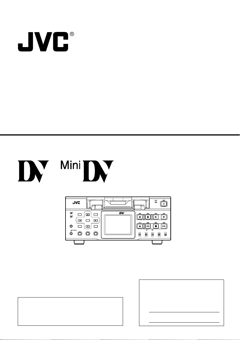
DV VIDEO CASSETTE RECORDER
INSTRUCTION MANUAL
BR-DV6000U
OPERATE
REC
PLAY PAUSE
MENU RESET
Mini
SEARCH–
MIC
HOLD
PHONES REC LEVEL
DISP
SET SEARCH+
BLANK CUE UP
CH-1/3 CH-2/4
PROFESSIONAL
BR-DV6000
Thank you for purchasing this JVC product.
Before operating this unit, please read the
instructions carefully to unsure the best
possible performance.
A.DUB
REW STOP FF
EJECT
AUDIO INPUT
COUNTER
CTL L
TC
UB
SELECT
MONITOR OUTPUT REMOTE
CH-1/2
DV
MIX
MIX
LINE
R
CH-3/4
Y/C
(CPN)
For Customer Use:
Enter below the Serial No. which is
located on the rear of cabinet. Retain
this information for future reference.
Model No. BR-DV6000U
Serial No.
LOCAL
LLT0033-001B-H
Page 2
1. Read all of these instructions.
2. Save these instructions for later use.
3. All warnings on the product and in the operating instructions should be adhered to.
4. Unplug this appliance system from the wall outlet before cleaning. Do not use liquid cleaners or
aerosol cleaners. Use a damp cloth for cleaning.
5. Do not use attachments not recommended by the appliance manufacturer as they may cause hazards.
6. Do not use this appliance near water – for example, near a bathtub, washbowl, kitchen sink, or
laundry tub, in a wet basement, or near a swimming pool, etc.
7. Do not place this appliance on an unstable cart, stand, or table. The appliance
may fall, causing serious injury to a child or adult, and serious damage to the
appliance.
Use only with a cart or stand recommended by the manufacturer, or sold with the
appliance.
Wall or shelf mounting should follow the manufacturer’s instructions, and should
use a mounting kit approved by the manufacturer.
An appliance and cart combination should be moved with care. Quick stops,
excessive force, and uneven surfaces may cause the appliance and cart
combination to overturn.
S3125A
8. Slots and openings in the cabinet and the back or bottom are provided for
ventilation, and to insure reliable operation of the appliance and to protect it from overheating, these
openings must not be blocked or covered. The openings should never be blocked by placing the
appliance on a bed, sofa, rug, or other similar surface. This appliance should never be placed near or
over a radiator or heat register. This appliance should not be placed in a built-in installation such as a
bookcase unless proper ventilation is provided.
9. This appliance should be operated only from the type of power source indicated on the marking label.
If you are not sure of the type of power supplied to your home, consult your dealer or local power
company. For appliance designed to operate from battery power, refer to the operating instructions.
10. This appliance system is equipped with a 3-wire grounding type plug (a plug having a third (grounding)
pin). This plug will only fit into a grounding-type power outlet. This is a safety feature. If you are unable
to insert the plug into the outlet, contact your electrician to replace your obsolete outlet. Do not defeat
the safety purpose of the grounding plug.
11. For added protection for this product during a lightning storm, or when it is left unattended and
unused for long periods of time, unplug it from the wall outlet and disconnect the antenna or cable
system. This will prevent damage to the product due to lightning and power-line surges.
12. Do not allow anything to rest on the power cord. Do not locate this appliance where the cord will be
abused by persons walking on it.
13. Follow all warnings and instructions marked on the appliance.
14. Do not overload wall outlets and extension cords as this can result in fire or electric shock.
15. Never push objects of any kind into this appliance through cabinet slots as they may touch dangerous
voltage points or short out parts that could result in a fire or electric shock. Never spill liquid of any
kind on the appliance.
16. Do not attempt to service this appliance yourself as opening or removing covers may expose you to
dangerous voltage or other hazards. Refer all servicing to qualified service personnel.
17. Unplug this appliance from the wall outlet and refer servicing to qualified service personnel under the
following conditions:
a. When the power cord or plug is damaged or frayed.
b. If liquid has been spilled into the appliance.
c. If the appliance has been exposed to rain or water.
d. If the appliance does not operate normally by following the operating instructions. Adjust only
those controls that are covered by the operating instructions as improper adjustment of other controls
may result in damage and will often require extensive work by a qualified technician to restore the
appliance to normal operation.
e. If the appliance has been dropped or the cabinet has been damaged.
f. When the appliance exhibits a distinct change in performance – this indicates a need for service.
18. When replacement parts are required, be sure the service technician has used replacement parts
specified by the manufacturer that have the same characteristics as the original part. Unauthorized
substitutions may result in fire, electric shock, or other hazards.
19. Upon completion of any service or repairs to this appliance, ask the service technician to perform
routine safety checks to determine that the appliance is in safe operating condition.
2
Page 3
SAFETY PRECAUTIONS
CAUTION
RISK OF ELECTRIC SHOCK
DO NOT OPEN
CAUTION: TO REDUCE THE RISK OF ELECTRIC SHOCK,
WARNING:
TO REDUCE THE RISK OF FIRE OR
ELECTRIC SHOCK, DO NOT EXPOSE THIS
APPLIANCE TO RAIN OR MOISTURE.
This unit should be used with 120 V AC only.
CAUTION:
To prevent electric shocks and fire hazards, DO
NOT use any other power source.
NOTE:
The rating plate (serial number plate) is on the rear of the unit.
INFORMATION
This equipment has been tested and found to comply
with the limits for a Class B digital device, pursuant to
Part 15 of the FCC Rules. These limits are designed to
provide reasonable protection against harmful
interference in a residential installation. This equipment
generates, uses, and can radiate radio frequency energy
and, if not installed and used in accordance with the
instructions, may cause harmful interference to radio
communications. However, there is no guarantee that
interference will not occur in a particular installation.
If this equipment does cause harmful interference to
radio or television reception, which can be determined
by turning the equipment off and on, the user is
encouraged to try to correct the interference by one or
more of the following measures:
● Reorient or relocate the receiving antenna.
●
●
● Consult the dealer or an experienced radio/TV
CAUTION
CHANGES OR MODIFICATIONS NOT APPROVED
BY JVC COULD VOID USER’S AUTHORITY TO
OPERATE THE EQUIPMENT.
THIS DEVICE COMPLIES WITH PART 15 OF THE
FCC RULES. OPERATION IS SUBJECT TO THE
FOLLOWING TWO CONDITIONS: (1) THIS DEVICE
MAY NOT CAUSE HARMFUL INTERFERENCE, AND
(2) THIS DEVICE MUST ACCEPT ANY INTERFERENCE RECEIVED, INCLUDING INTERFERENCE
THAT MAY CAUSE UNDESIRED OPERATION.
DO NOT REMOVE COVER (OR BACK).
NO USER-SERVICEABLE PARTS INSIDE.
REFER SERVICING TO QUALIFIED SERVICE PERSONNEL
The lightning flash with arrowhead symbol, within an
equilateral triangle, is intended to alert the user to the
presence of uninsulated “dangerous voltage” within
the product’s enclosure that may be of sufficient
magnitude to constitute a risk of electric shock to
persons.
The exclamation point within an equilateral triangle is
intended to alert the user to the presence of important
operating and maintenance (servicing) instructions
in the literature accompanying the appliance.
Increase the separation between the equipment and receiver.
Connect the equipment into an outlet on a circuit
different from that to which the receiver is connected.
technician for help.
ATTENTION
RISQUE D’ELECTROCUTION
NE PAS OUVRIR
ATTENTION: POUR EVITER TOUT RISQUE D’ELECTROCUTION
SE REFERER A UN AGENT QUALIFIE EN CAS DE PROBLEME.
AVERTISSEMENT:
POUR EVITER LES RISQUES
D’INCENDIE OU D’ELECTROCUTION, NE
PAS EXPOSER L’APPAREIL A
L’HUMIDITE OU A LA PLUIE.
Ce magnétoscope ne doit être utilisé que sur
du courant alternatif en 120 V.
ATTENTION:
Afin d’éviter tout resque d’incendie ou
d’électrocution, ne pas utiliser d’autres
sources d’alimentation électrique.
REMARQUE:
La plaque d’identification (numéro de série) se
trouve sur le panneau arrière de l’appareil.
WARNING:
The battery used in the BR-DV6000U must be
replaced by a JVC authorized service dealer only.
This digital apparatus does not exceed the Class B
limits for radio noise emissions from digital
apparatus as set out in the interference-causing
equipment standard entitled “Digital Apparatus”,
ICES-003 of the Department of Communications.
Cet appareil numérique respecte les limites de
bruits radioélectriques applicables aux appareils
numériques de Classe B prescrites dans la norme
sur le matériel brouilleur: “Appareils Numériques”,
NMB-003 édictée par le ministre des Communications.
NE PAS OUVRIR LE BOITER.
AUCUNE PIECE INTERIEURE N’EST
A REGLER PAR L’UTILISATEUR.
Le symbole de l’éclair à l’intérieur d’un triangle
équilatéral est destiné à alerter l’utilisateur sur la
présence d’une “tension dangereuse” non isolée
dans le boîtier du produit. Cette tension est suffisante
pour provoquer l’électrocution de personnes.
Le point d’exclamation à l’intérieur d’un triangle
équilatéral est destiné à alerter l’utilisateur sur la
présence d’opérations d’entretien importantes au
sujet desquelles des renseignements se trouvent
dans le manuel d’instructions.
*Ces symboles ne sont utilisés qu’aux Etats-Unis.
3
Page 4
Thank you for purchasing our
DV Video Cassette Recorder
BR-DV6000.
As this is a DV-format video cassette recorder,
video cassettes with the or logo can
be used with it.
DVCAM cassettes can be recorded in the DV
format.
● In order to prevent crumpling due to tape
slack, do not perform important recording
within the first and last 2 – 3 minute-run of
the tape.
● Recorded video (sound) is meant for personal entertainment only and must not be
used for other purposes without the prior
consent of the copyright owner.
● JVC shall not guarantee the quality of recording and playback should BR-DV6000 fail
to function normally due to defects, either
of the unit itself or the video cassette tapes.
MAIN FEATURES
● DV format
High picture and sound quality by digital technology.
● Compatible mechanisms for standard/mini DV cassette tapes
It records on and plays back DV cassette tapes of the
standard and mini size. (SP mode only)
Recording in the DV format can be performed on
DVCAM cassette tapes.
● Only PAL/NTSC DVCAM tapes are detected automatically in playback mode.
● Equipped with composite, component and Y/C input & output terminals.
● Equipped with DV IN/OUT terminals. (IEEE1394)
It can exchange digital signals with IEEE1394-compatible devices.
● Both NTSC and PAL signals supported
BR-DV6000 can playback or record PAL tapes through
the DV input. For PAL, please set the PB/DV IN menu
item to PAL.
For analog signal input, only NTSC is supported.
● RS-422A and JVC bus interface supported
RS-422A-compatible edit controller RM-G820 and JVC
bus-compatible edit controller RM-G800/G805 can be
used for editing.
● Optionally, the RS-232C interface can be used.
● Recording and playback of time codes
● Time code I/O terminal
Slave lock is allowed if BR-DV6000 is connected to an
external time code generator.
● SYNC IN terminal
External synchronization signals can be input.
● Audio-dubbing function (after-recording)
If the sampling frequency is 32 kHz, audio dubbing can
be performed into CH3 and CH4 (except during DV input).
● Backup recording function
With the combined use of other DV machines, long-time
continuous recording is possible.
● Using the SERIAL REMOTE OUT terminal or DV terminal, dubbing with other recorders is possible only
with playback operation by BR-DV6000. (Replication
function)
● Equipped with a 2.5-inch color LCD
Images, status display and menu display can be viewed.
● Multi-cue up
Up to 5 points of the tape position can be registered
and cued up.
● Index/blank search function
It can search for positions where index signals are recorded and unrecorded parts.
● Repeat play function
There are 3 types of repeat function.
(INDEX/ VIDEO END/ TAPE END)
● Recording/playback with an external timer
● With the use of the network board SA-DV6000 (sold
separately), image and audio streaming data can be
recorded on a CF card, and with a LAN card, streaming data can be transmitted to a PC.
● With the XLR IN board SA-X61U or XLR OUT board
SA-X62U (sold separately), audio input/output via
the XLR terminal is possible.
4
Page 5

Table of Contents
INTRODUCTION
Remarks of usage ......................................... 6
Regular maintenance .................................... 7
Cleaning tape ................................................ 8
Cassette tape ................................................ 8
Condensation ................................................ 9
NAMES AND FUNCTIONS OF PARTS
Front panel .................................................. 10
Rear panel ................................................... 16
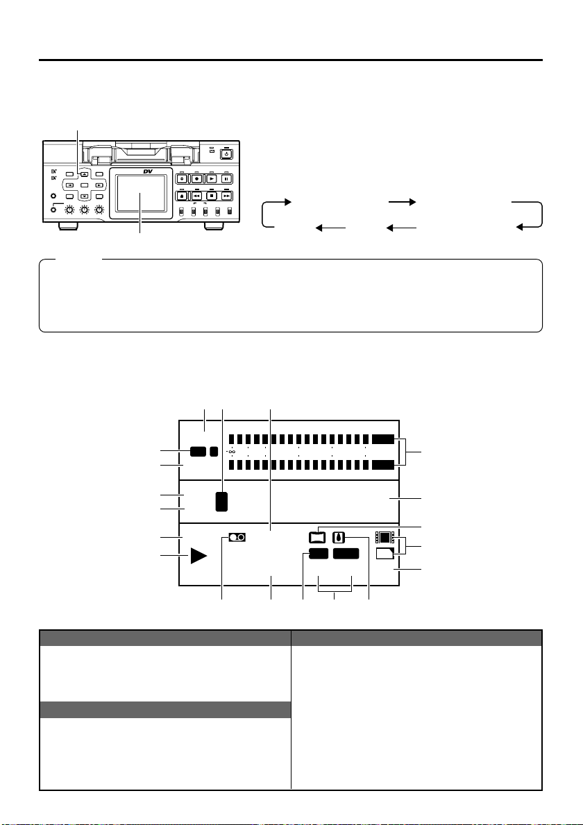
ON-SCREEN DISPLAY
On-screen display ....................................... 20
Status display .............................................. 21
Status/Event display .................................... 23
Alarm display ............................................... 24
LCD display .................................................26
CONNECTION
Connecting video signals ............................ 28
Connecting audio signals ............................ 30
Connecting to editing system ...................... 32
Connecting with serial remote terminals ..... 34
Connecting the AC adapter ......................... 35
PREPARATION
Tu r ning on/off the power .............................. 36
Operation method (main unit/remote
controller) and operation lock mode ............ 37
Loading/Ejecting cassette ........................... 38
Setting the LCD display ............................... 39
Setting/Displaying date and time ................. 40
RECORDING
Setting ......................................................... 42
Recording procedure ................................... 43
Audio dubbing ............................................. 44
Backup recording function ........................... 45
Recording with serial remote terminals ....... 46
External timer recording .............................. 47
PLAYBACK
Setting ......................................................... 48
Basic playback procedure ........................... 49
Special playback functions ..........................50
Search function ........................................... 52
Repeat playback.......................................... 53
Multi cue-up ................................................. 54
External timer playback ............................... 56
Dubbing with another machine using the
SERIAL REMOTE OUT/DV terminals ......... 57
TIME CODE
Displaying the time code ............................. 58
Presetting the time code ............................. 59
Recording the time code ............................. 60
Playing back the time code ......................... 63
EDIT
Editing with an RS-422A/JVC bus edit
remote controller ......................................... 64
Using a non-linear editing system ............... 68
MENU SCREENS
Structure of the Menu screens .................... 69
Setting the menus ....................................... 70
Description of the Menu screens ................. 72
RS-232C INTERFACE
Command tables ......................................... 84
RS-232C specifications ............................... 85
RS-232C commands ...................................86
OTHERS
Warning display ........................................... 97
Troubleshooting ...........................................99
Checking the hour meter ........................... 100
Optional devices ........................................ 101
Installing SA-K46U RS-232C interface
board ......................................................... 102
Specifications ............................................ 103
Supplement ............................................... 105
5
Page 6

INTRODUCTION
Remarks of usage
Place of storage and use
Avoid storing or using this VCR in the following
places:
● Excessively hot or cold places beyond the allowable temperature for operation (5˚C –
40˚C).
● Humid or dry places beyond the allowable
humidity range for operation (30% – 80% RH).
● Dusty or sandy places.
● Places exposed to oil, smoke or steam, such
as the kitchen vicinity.
● Intensely vibrating or unstable places.
● Places prone to condensation.
● Places that generate strong magnetic fields,
e.g., near a transformer or motor.
● Places near devices that generate electric
waves, e.g., a transceiver or mobile phone.
● Places that generate X-ray radiation or corrosive gases.
Handling the unit
● Do not place heavy objects on the unit, like a
monitor or TV.
● Do not insert foreign objects into the cassette
slot.
● Mind your finger when loading a cassette
tape.
Be careful not to get your fingers clamped
when loading the cassette to prevent injury.
● Place this unit out of reach of young children
to prevent injury as fingers may get clamped
while a cassette tape is being loaded.
● Do not block the ventilation openings.
● Avoid strong impact to the unit. Do not drop
the unit.
● Remove the cassette tape from the cassette
slot when transporting the unit.
● Remove the AC adapter to save energy when
the unit is not in use.
Maintaining the unit (Turn off the power
before performing maintenance work.)
Wipe the unit with a soft cloth.
Do not wipe it with thinner or benzene as it may
melt or tarnish the unit surface.
For stubborn stains, use water-diluted neutral
detergent and then wipe it dry.
Use the supplied AC adapter to connect
the unit to a power source.
Use the supplied power cord.
Using a different type or damaged cord may
cause fire or electric shock.
Do not use the supplied power cord for
other models.
LCD screen
The LCD screen is designed and manufactured
with high-precision technology.
Minute black dots may appear or bright (red, blue
and white) dots are permanently lit. This phenomenon is not a product defect and the dots
are not recorded.
6
Page 7
Regular maintenance
This unit uses consumables or components that will wear off. If a worn-out or deteriorated component continues to be used, it may cause the unit to break down. To prevent this, perform routine
maintenance using the head-cleaning tape. With the head-cleaning tape alone, however, the entire
tape-winding mechanism cannot be completely cleaned.
Perform regular maintenance of the components as shown below.
Regular maintenance
The tasks of maintenance involved are similar to that of replacing the engine oil or tire of a car.
Depending on the number of usage hours, inspect or replace the components as follows:
Number of hours 500H 1000H 1500H 2000H 4000H
Drum assembly (including head)
Head cleaner
Tape guide, roller
Reel disk, tension bands — —
—:Inspection
: Cleaning, inspection and
adjustment
: Cleaning and inspection;
Replacement if necessary
: Replacement
Work and frequency of maintenance depend on the environment and usage. The above information serves only as a guide.
Usage Time :You can check the drum usage time with the hour meter display.
For details, refer to page 100, “Checking the hour meter.”
Maintenance consultation :For details on the maintenance plan and fee, consult with your
JVC-authorized service agent.
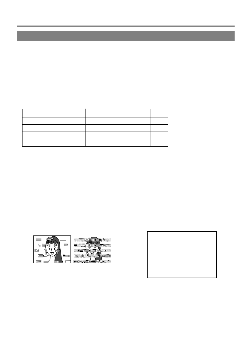
Head cleaning
• Recording or playing back with a dirty head
will result in block noise or disrupted sound.
Perform regular head cleaning to maintain superior image and sound quality.
Block Noise
•For information on how to use the head cleaning tape and the relevant remarks, refer to
page 8, “Cleaning tape”.
• If the head is dusty, “HEAD CLEANING REQUIRED!” will be displayed on the monitor
when this unit plays a tape.
HEAD CLEANING REQUIRED!
7
Page 8
INTRODUCTION
Cleaning tape
Use a JVC cleaning tape.
Follow the instructions below for using the cleaning tape.
1.
Run the tape for 10 seconds in the PLAY
mode. (Thereafter, it stops automatically
and enters the STOP mode.)
• After loading the cleaning tape, press the
PLAY button.
2.
For a single cleaning session, it can be repeated up to 4 times.
3.
Refer to the following table as a guide for
cleaning.
Notes
● Under low humidity conditions, (10% RH to
30% RH), perform head cleaning at intervals
of half of the periods stated in the table.
● If an M-DV80 tape is used immediately after
cleaning, the message, “HEAD CLEANING
REQUIRED!” may not disappear. It does only
after the tape has run for some time.
● Use the cleaning tape at room temperature
(10˚C to 35˚C).
● Instructions for using the cleaning tape stated
on a sheet inside its storage case may be
different in part from those stated here.
Follow the instructions in this manual.
Operating environment
Frequency of 1 to 2 times every 1 to 2 times every 1 to 2 times every
cleaning 5 hours 20 to 30 hours 5 hours
Low temperature Room temperature High temperature
5˚C to 10˚C 10˚C to 35˚C 35˚C to 40˚C
Cassette tape
BR-DV6000 can record onto and playback standard DV and mini DV cassette tapes (for SP mode
only).
Use the following JVC cassettes with the or the
logo.
●
●
Standard DV cassettes
LA-DV276
LA-DV186
LA-DV124
Mini DV cassettes
M-DV63PRO
M-DV60
M-DV30
Memo
● DVCAM cassette can be recorded in the DV
format.
● Tapes recorded in the DVCAM format can be
played (SP Mode).
● M-DV80 cassettes (Mini DV 80min tape) cannot be used with this unit.
Remarks on the use of tape
● Do not load the videotape in the wrong direction.
● Store the tape only after it has been fully rewound, so as to avoid damaging the tape.
● Store the cassette in places low in humidity, well-ventilated and fungus-proof.
● When a cassette tape is used repeatedly, noise may increase due to e.g., dropout, etc. hence
affecting its performance. Do not use dirty or damaged tapes as they will shorten the life span of the
rotation head.
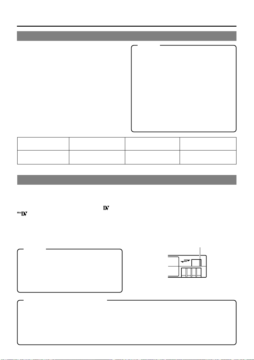
Erasure prevention
DV cassettes have a safety slide at the back to
prevent accidental erasure.
•
To prevent accidental erasure of important
records, push the slide to the “SAVE” position.
•
To record, push the slide to the “REC” position.
Slide
REC
SAVE
8
Page 9
For recording and storing videotapes in the best condition
Observe the following instructions for the best recording and storage of videotapes.
•Take care of the conditions of handling videotapes.
It is recommended that you record and store videotapes in the environment below.
Storage
Recording Short period Long period
(Up to 10 years) (Over 10 years)
Temperature 17°C to 25°C 15°C to 23°C 15°C to 19°C
Humidity 30% to 70% 40% to 55% 25% to 35%
Hourly temperature change Less than 10°C – –
Hourly humidity change Less than 10% – –
• Do not leave the videotapes neglected for a long period.
If videotapes are left wound for a long period of time, it may result in distortion of the tape. Also it
may cause tape-to-tape adhesion (known as blocking). It is recommended that videotapes be
unspooled and rewound once a year for refreshing.
• When tapes are not in use, store them in cases and on end.
Storage cases protect videotapes from humidity, dust and ultraviolet. Keep tapes in cases and do
not store them lying flat. When housed in a horizontal position, pressure from other tapes can
cause distortions and deformations of the tape edges.
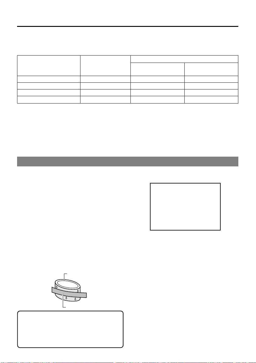
Condensation
• When this unit is moved from a cold to a warm
place abruptly, the vapor in the warm air will
come into contact with the head drum or the
tape guides, which are not warmed enough.
When chilled, the vapor turns into droplets of
water. This state is known as condensation.
When condensation occurs, the videotape
adheres to the head drum or the tape guides
and will be damaged.
• Condensation occurs on this unit in the fol-
lowing circumstances:
* It is moved abruptly from a cold place to a
warm place.
* It is used in a place immediately after the
heater has been turned on, or when cold
breeze from an air-conditioner blows onto it.
* It is used at a place of high humidity.
Head drum
Videotape
When a cassette tape is loaded, do not transport e.g., from a cold outdoor place to a warm
room thus subjecting the unit to drastic temperature changes.
After moving the unit, do not use it until the
inner mechanism stabilizes.
• When condensation occurs, the monitor displays the following warning:
CONDENSATION ON DRUM
Leave the unit with the power ON and wait
until the WARNING message disappears.
• Prevention of condensation
When transporting BR-DV6000 from a cold
to a warmer place abruptly, first remove the
cassette tape. Then place BR-DV6000 in a
plastic bag and seal it before transporting.
Ta ke out BR-DV6000 from the sealed plastic
bag only after it has the same temperature
as the surroundings.
9
Page 10
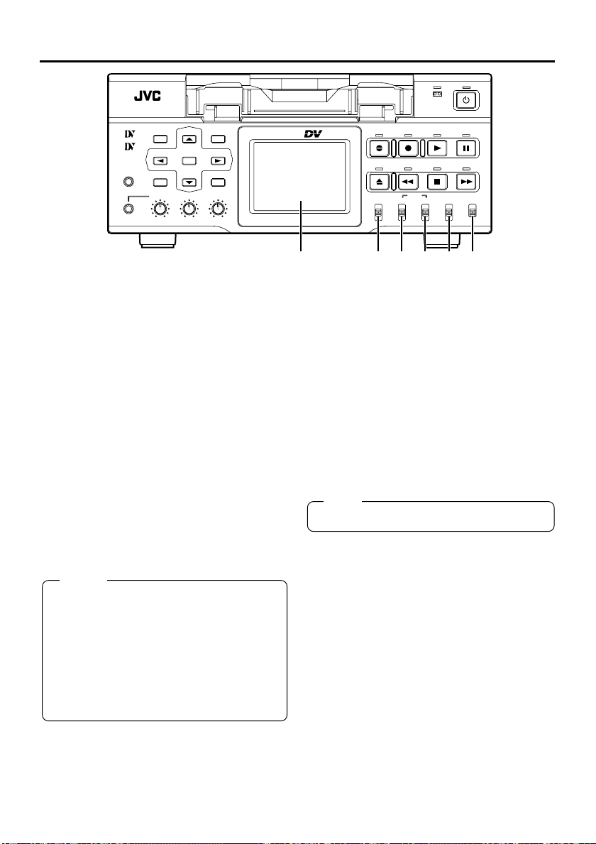
NAMES AND FUNCTIONS OF PARTS
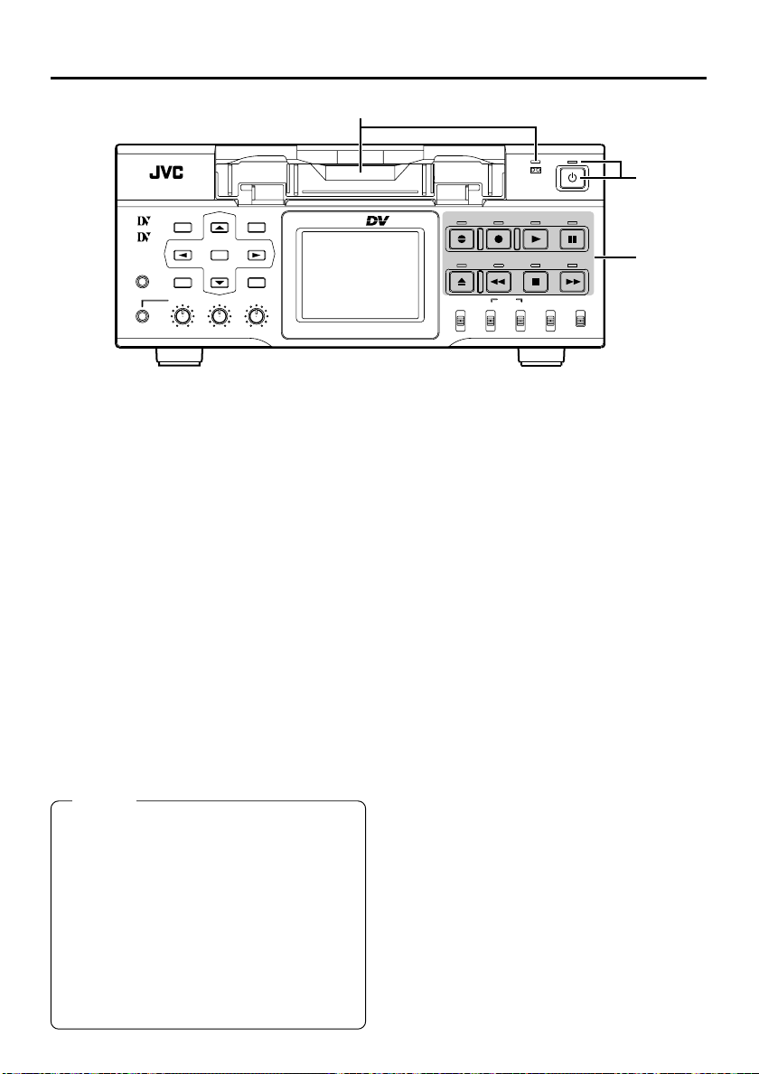
1
– Front panel –
MENU RESET
Mini
MIC
DISP
SEARCH–
SET SEARCH+
BLANK CUE UP
HOLD
PHONES REC LEVEL
CH-1/3 CH-2/4
1 Cassette loading slot/LED
•For loading a cassette into or unloading it from
the slot.
Insert a standard DV cassette or a mini DV
cassette. (☞ Page 38)
• When BR-DV6000 is in the OPERATE OFF
state and a cassette is loaded, it changes to
the OPERATE ON state.
• With a cassette loaded, the LED lights up in
green.
When a cassette is being loaded or ejected,
the LED flashes.
2 [OPERATE] button/LED
• Press this button to turn on the power and
BR-DV6000 becomes ready for operation.
(Operate ON)
Press this button again when BR-DV6000 is
already on to turn off the power.
(Operate OFF)
• OPERATE LED lights up as follows.
Operate ON : the green LED lights up
Operate OFF : the red LED lights up
VCR error : the red LED blinks
Memo
● If DC IN MODE in the SYSTEM MENU screen
is set to “OPE ON” or the Timer Switch is set
to “REC” or “PLAY” and power is supplied to
the DC IN terminal located on the rear panel,
BR-DV6000 goes into the OPERATE ON
state even if this button is not pressed.
● Even after the power is turned off with this
button, BR-DV6000 is live with a small amount
of electricity.
Therefore, if BR-DV6000 is not to be used
for a long period of time, please remove the
AC adapter to save energy.
PROFESSIONAL
BR-DV6000
2
3
A.DUB
REC
EJECT
REW STOP FF
AUDIO INPUT
COUNTER
MONITOR OUTPUT REMOTE
CTL L
CH-1/2
TC
MIX
MIX
R
CH-3/4
UB
OPERATE
PLAY PAUSE
SELECT
DV
LINE
Y/C
(CPN)
LOCAL
3 Operation buttons
[A. DUB] Audio dubbing button/LED
• Press this button for audio dubbing (after-recording).
For audio dubbing, set AUDIO MODE in the
AUDIO MENU screen to “32K”.
The sound produced by the MIC terminal #
or the AUDIO IN terminal is recorded on channels CH3 and CH4.
• During audio dubbing, the red A. DUB LED
lights up.
• If the INPUT SELECT switch is set to DV,
audio dubbing cannot be performed.
(☞ Page 44 “Audio Dubbing”)
[REC] button/LED
• Hold down this button and press the PLAY
button to start recording. During recording,
the red LED lights up.
• Hold down this button and press the PAUSE
button to pause recording.
• If this button is pressed during recording, an
index signal is recorded on the tape (when
INDEX WRITE in the SYSTEM MENU screen
is set to ON).
• When this button is pressed in the STOP
mode, the time code generator value can be
checked while the button is being held down.
If TC DUPLICATE Menu is set to AUTO or
NON DROP, the time code, date and time of
the DV input can be checked.
• If this button is pressed during playback, the
input signal can be checked while the button
is held down. (EE check)
EE check is not available for DV signal input.
10
Page 11

[PLAY] button/LED
• Press this button to start playing back a tape.
During playback, the green LED lights up.
• When recording is paused, press this button
to resume recording.
• When audio dubbing is paused, press this
button to resume audio dubbing.
[PAUSE] button/LED
• During recording, press this button to pause
it.
• In the PLAYBACK or STOP mode, press this
button to enter the STILL mode. In the RECORDING PAUSE or STILL mode, the green
LED lights up.
• When BR-DV6000 is in the STILL mode, hold
down the A.DUB button and press this button to enter into the audio-dubbing pause
mode.
•When BR-DV6000 is in the STILL mode,
press this button for frame advance playback.
Memo
Still images or images in frame advance can
be selected with STIL/F.ADV of the SYSTEM
(1/2) MENU screen.
[FF] button/LED
• When BR-DV6000 enters the STOP mode,
press this button to fast-forward the tape.
• When BR-DV6000 is in the PLAYBACK or
STILL mode, press this button for fast-forward
playback. The fast forward playback speed
can be changed by pressing the SEARCH +/
: button * or the SEARCH –/; button
(when “;,:” KEY FUNC in the SYSTEM (1/
2) Menu screen is set to VAR).
(☞ Page 50 “Search Mode”)
• Hold down the PLAY button and press this
button to perform playback in the forward direction at 1.07 times the normal speed. At
this state, if the PLAY button is released first,
the playback continues at 1.07 times the normal speed.
If this button is released first, it plays back at
the normal speed.
• During fast-forwarding or fast-forward playback, the LED lights up in green.
[STOP] button
• Press this button to stop operation.
• When BR-DV6000 is in the STANDBY OFF
mode, press this button to enter the
STANDBY ON mode.
Memo
There are two stop modes.
● STANDBY OFF: For protecting the tape and
the drum, the drum does not rotate.
● STANDBY ON: The drum rotates so that it
starts up faster after BR-DV6000 moves into
another mode.
[REW] button/LED
• When BR-DV6000 enters the STOP mode,
press this button to rewind the tape.
• When BR-DV6000 is in the PLAYBACK or
STILL mode, press this button for reverse
playback. The rewind playback speed can be
changed by pressing the SEARCH +/: button * or the SEARCH –/; button (when
“;,:” KEY FUNC in the SYSTEM (1/2) Menu
screen is set to VAR).
(☞ Page 50 “Search Mode”)
• Hold down the PLAY button and press this
button to perform playback in the reverse direction at 0.9 times the normal speed. At this
state, if the PLAY button is released first, the
playback continues at 0.9 times the normal
speed.
If this button is released first, it plays back at
the normal speed.
• During rewinding or rewind playback, the LED
lights up in green.
[EJECT] button
• Press this button to eject the cassette.
Memo
● It takes about 6 seconds for the cassette to
be ejected.
● The cassette can be ejected even when BRDV6000 is in the OPERATE OFF mode. After the eject action is completed, BR-DV6000
returns to the OPERATE OFF mode.
11
Page 12
NAMES AND FUNCTIONS
OF PARTS
MENU RESET
Mini
MIC
4 [REMOTE/LOCAL] switch
This switch is used to select how BR-DV6000
is to be operated.
LOCAL : Use this setting if BR-DV6000 is to
be controlled with the key operation
of the unit.
REMOTE : Use this setting if BR-DV6000 is to
be controlled using the edit controller connected to the REMOTE 1 (9PIN) terminal or REMOTE 2 (12PIN) terminal.
When it is set to REMOTE, settings
can be performed at the REMOTE
(1/2) MENU screen to enable/disable operation via the 9-PIN or 12PIN REMOTE terminal.
The 9-PIN REMOTE 1 terminal can
be selected using REMOTE SEL 9
PIN while the 12-PIN REMOTE 2
terminal can be selected with REMOTE SEL JVC.
Memo
● To control BR-DV6000 with the SERIAL REMOTE terminal or DV terminal, this switch setting can be set up with REMOTE SEL SERIAL or REMOTE SEL DV in the REMOTE
(1/2) MENU screen. (☞ Page 75)
● If it is set to REMOTE, the buttons that can
be operated from the unit are selectable from
LOCAL FUNCTION in the REMOTE (1/2)
MENU screen.
12
DISP
SEARCH–
SET
SEARCH+
BLANK CUE UP
HOLD
PHONES REC LEVEL
CH-1/3 CH-2/4
PROFESSIONAL
BR-DV6000
– Front panel – (continued)
OPERATE
A.DUB
REC
PLAY PAUSE
EJECT
REW STOP FF
AUDIO INPUT
COUNTER
MONITOR OUTPUT REMOTE
CTL L
TC
MIX
R
UB
CH-1/2
CH-3/4
SELECT
DV
MIX
LINE
Y/C
LOCAL
(CPN)
9 8 7 6 5 4
5 [INPUT SELECT] switch
This switch is used to select input signals.
DV :For DV signals of the DV IN/OUT
terminal (IEEE1394)
LINE :For inputting the composite images
of the LINE IN terminal and analog audio signals.
Y/C (CPN) :For inputting the YC separate video
signal of the Y/C IN terminal and
the component video signal of the
COMPONENT IN terminal. The
selection of the YC separate signal or the component video signal
can be done with VIDEO INPUT
SEL in the VIDEO MENU screen.
For audio, analog sound is input.
Note
Switching is invalid during recording.
6 [AUDIO OUTPUT] switch
Use this switch to select the audio channel from
the headphone terminal and the AUDIO OUT
terminal located on the rear panel.
This switch is valid in the following conditions.
• During playback of tapes recorded in the 32k
audio mode
• In the EE mode for DV input in the 32k audio
mode
• During audio dubbing
CH-1/2 :For outputting the sound of the
MIX :For outputting the mixed sound of
CH-3/4 :For outputting the sound of CH3 and
channels CH1 and CH2.
CH1 and CH3 from the CH-1/3 AUDIO OUT terminal and the mixed
sound of CH2 and CH4 from the CH2/4 AUDIO OUT terminal.
CH4.
Page 13
Memo
● For the MIX setting, noise is sometimes generated. If it occurs, set it to CH-1/2 or CH-3/4.
● In the 48 K audio mode, it is fixed at channels CH1 and CH2 regardless of the setting
of the switch.
7 [AUDIO MONITOR] switch
Use this switch to select the audio channel for
output signals from the headphone terminal and
the AUDIO MONITOR terminal located on the
rear panel.
The output signal of the AUDIO MONITOR OUT
terminal is monaural.
L :For outputting the sound of CH1.
MIX :For outputting the mixed sound of CH1
and CH2.
R :For outputting the sound of CH2.
Memo
In the following conditions, if this switch and the
6 AUDIO OUTPUT switch are used in combi-
nation, the AUDIO MONITOR OUT outputs the
sounds listed as in the following table.
• During playback of tapes recorded in the
32 K audio mode
• In the EE mode for DV input in the 32 K audio
mode
• During audio dubbing
AUDIO switch
MONITOR
L
MIX
R
OUTPUT
CH-1/2
MIX
CH-3/4
CH-1/2
MIX
CH-3/4
CH-1/2
MIX
CH-3/4
MONITOR OUT
output channel
CH1
CH1/3 mix
CH3
CH1/2 mix
CH1/2/3/4 mix
CH3/4 mix
CH2
CH2/4 mix
CH4
8 [COUNTER] switch
The switch changes the contents of the counter display of the 9 LCD and the monitor.
CTL : It displays the counter in hour, minute,
second and frame based on CTL (control signal).
TC : It displays the time code data.
UB : It displays the user’s bit (UB).
9 LCD
In the playback, still or search mode, it dis-
plays the playback image.
In the recording, recording pause, stop, fast-forwarding or rewinding mode, it displays the input image.
The following information is also dis-
played.
•Various types of information (status display),
e.g., operation mode, date/time, counter
• Menu screen
•Warning display
(For details, ☞ Page 20)
Memo
● Use the * DISP button to enable/disable the
LCD display and the display style.
● LCD-related settings, e.g., brightness adjustment of the LCD, are performed in the DISPLAY MENU screen.
(☞ Page 39 “Setting the LCD display”)
(☞ Page 82 “DISPLAY MENU screen”)
● If the same image pattern is kept displayed
on the LCD display for a prolonged period of
time, “ghosting”, the permanent etching of a
pattern on a display screen, may occur. To
prevent this, turn off the LCD display when it
is not in use.
13
Page 14
NAMES AND FUNCTIONS
OF PARTS
$
%*^ &
MENU RESET
Mini
MIC
#
!@ 0
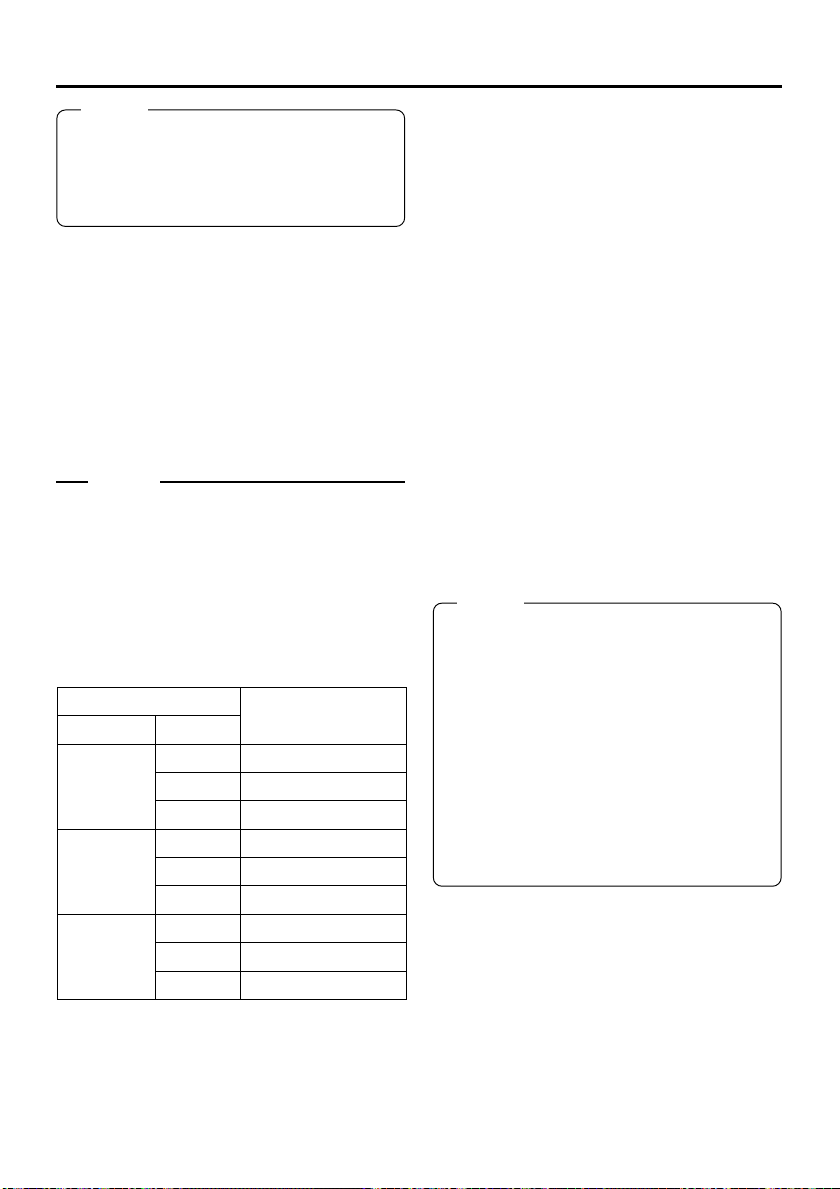
0 [REC LEVEL] Volume for audio
recording level for CH1/3 and
CH2/4
Use the switch to adjust the audio recording level
for CH1 and CH2.
During audio dubbing, the audio recording level
for CH3 and CH4 can be adjusted with this
switch.
Memo
● During DV input, the volume control is not
effective.
● During MIC input, only the volume for CH1/3
REC LEVEL is valid.
! [PHONES] terminal
This is the mini jack terminal for connecting to
the headphone. (Stereo ø3.5)
• When BR-DV6000 plays back tapes recorded
in the 32 kHz mode, the audio channel for
outputting from this terminal is selected with
the 6 AUDIO OUTPUT switch.
@ [PHONES] Headphone volume
Use this switch to adjust the output level of the
PHONES terminal.
Both channels are adjusted at the same time.
# [MIC] terminal
This is the mini jack terminal for monaural microphone input.
To input sound from a microphone, set the [INPUT SELECT] switch to LINE or Y/C (CPN).
If a microphone is connected, sound for the AUDIO IN terminal located on the rear panel cannot be input.
The sound of the microphone is recorded to
CH1/CH2 in the recording mode and CH3/CH4
in the audio-dubbing mode.
DISP
SEARCH–
SET
SEARCH+
BLANK CUE UP
HOLD
PHONES REC LEVEL
CH-1/3 CH-2/4
– Front panel – (continued)
PROFESSIONAL
BR-DV6000
$ [HOLD] button
If this button is pressed in the LCD enlarged
display mode, the time code preset screen will
be displayed on the LCD. When the time code
preset screen is displayed, press this button to
return to the normal display.
(☞ Page 59 “Presetting time code”)
% [MENU] button
If this button is pressed when BR-DV6000 is in
the STOP/STILL mode or when no cassette is
loaded, the menu is displayed on the LCD or
the monitor connected to the VIDEO MONITOR
OUT terminal.
When the menu is displayed, press this button
to return to the normal display.
(☞ Page 70 “Setting the menu”)
^ [RESET] button
•To reset the CTL counter display to “00”, press
this button.
• If this button is pressed when the time code
preset screen is displayed, all the digits of
the time code or the user’s bit are reset to
“00”.
• When the Multi Cue-up screen is displayed,
press this button to clear the registered cueup points.
& [CUE UP] button
When the 8 COUNTER switch is set to TC,
press this button to display the Multi Cue-up
screen on the monitor or LCD.
When the Multi-Cue-up screen is displayed,
press this button to start searching the selected
tape position.
(☞ Page 54 “Multi Cue-up”)
A.DUB
REC
EJECT
REW STOP FF
AUDIO INPUT
COUNTER
MONITOR OUTPUT REMOTE
CTL L
CH-1/2
TC
MIX
MIX
R
CH-3/4
UB
OPERATE
PLAY PAUSE
SELECT
DV
LINE
Y/C
(CPN)
LOCAL
14
Page 15

* Special functions/Setting buttons
The following buttons have different functions
depending on whether the normal screen or the
setting screen is displayed.
Setting screens:
Menu, Date/Time setting, Time code preset and
Multi Cue-up
[DISP/8] button
• During normal display, this button is used to
enable/disable the LCD or select display style.
When this button is pressed, the LCD display changes in the following manner.
Enlarged character display ¥ Image/
enlarged character display ¥ Image/charac-
ter display ¥ Image display ¥ No display
¥ Enlarged character display...
• When the setting screen is displayed, this button is used to select the items or setting values.
[BLANK/9] button
• When BR-DV6000 is in the stop mode, press
this button to start blank search. It searches
the unrecorded part of the tape and goes into
the still mode.
(☞ Page 52 “Blank search”)
• When the setting screen is displayed, this button is used to select the items or setting values.
[SEARCH+/:] button
• During normal display, the function of this button can be selected using “;,:” KEY FUNC
in the SYSTEM (1/2) Menu screen.
If it is set to VAR, the searching speed increases if this button is pressed during a
search operation.
(☞ Page 50 “Search mode”)
If it is set to INDEX, press this button to start
forward index search. This function is not effective during recording or recording pause.
(☞ Page 52 “Index search”)
• When the setting screen is displayed, this button is used to select items or setting digits.
[SEARCH–/;] button
• During normal display, the function of this button can be selected using “;,:” KEY FUNC
in the SYSTEM (1/2) Menu screen.
If it is set to VAR, the searching speed decreases if this button is pressed during a
search operation.
(☞ Page 50 “Search mode”)
If it is set to INDEX, press this button to start
reverse index search. This function is not effective during recording or recording pause.
(☞ Page 52 “Index search”)
• When the setting screen is displayed, this button is used to return to the previous menu or
select setting digits.
[SET] button
• When the Menu screen, Date/Time setting
screen or the Multi Cue-up screen is displayed, press this button to confirm the setting value.
• When the time code preset screen is displayed, press this button to preset the selected time codes or user’s bit to the time code
generator.
15
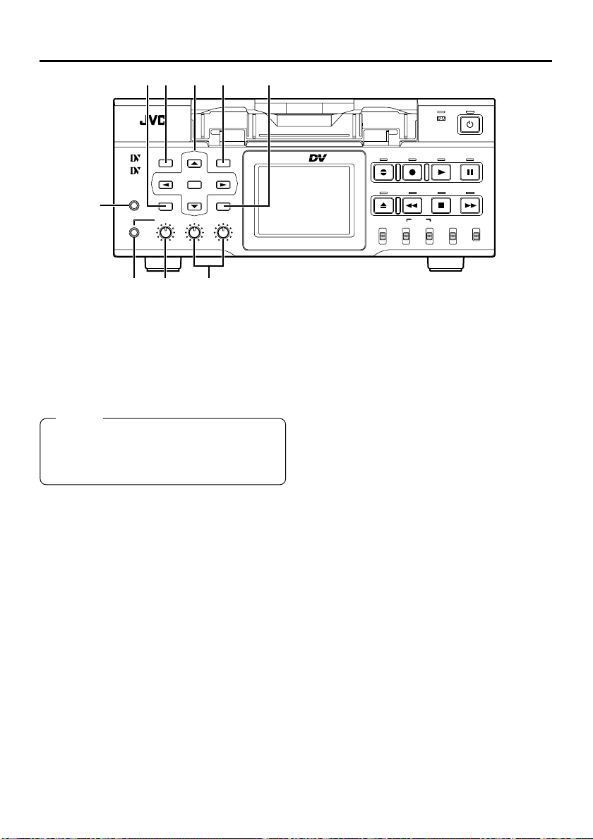
Page 16
NAMES AND FUNCTIONS
OF PARTS
1 6 7 ! @
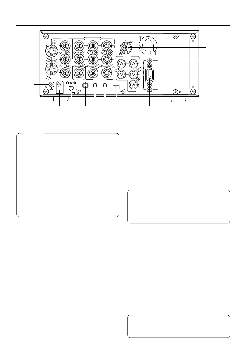
– Rear panel –
2
3
VIDEO
LINE
Y/C
IN
OUT
Y
COMPONENT
B-YR-Y
4
SIGNAL
GND
MONITOR
OUT
DC12V
SYNC IN
DV
IN/OUT
IN OUT
TIME CODE
IN OUT
SERIAL
REMOTE
5809#%
1 [VIDEO LINE IN] terminal (BNC)
This is the input terminal for composite video
signals.
•To input video via this terminal, set the INPUT SELECT switch located on the front
panel to “LINE”.
2 [VIDEO Y/C IN] terminal (4-PIN)
This is the input terminal for YC separate video
signals.
•To input video via this terminal, the following
settings are required.
Set VIDEO INPUT SEL in the VIDEO Menu
screen to “Y/C”.
Set the INPUT SELECT switch located on
the front panel to “Y/C (CPN)”.
• When wide-screen ID signals are input, the
wide-screen ID signal is recorded.
3 [VIDEO LINE OUT] terminal (BNC)
This is the output terminal for composite video
signals.
4 [VIDEO Y/C OUT] terminal (4-PIN)
This is the output terminal for Y/C separate video
signals.
• When tapes that have recorded wide-screen
signals are played back, the wide-screen ID
signal is output.
REMOTE2
IN
AUDIO
OUT
CH 1/3 CH 2/4
IN
OUT
OFF
REC PLAY
TIMER
MONITOR
OUT
REMOTE1
5 [VIDEO MONITOR OUT] terminal
(BNC)
This terminal is for connecting to a monitor-TV.
• It outputs composite video signals.
• It displays the Menu setting screen, Date/
Time setting screen and warning information.
• If DISPLAY in the DISPLAY Menu screen is
set to “ON” or “AUTO”, information will be displayed on-screen, e.g., the operation mode,
date/time and counter. (☞ Page 20)
6 [COMPONENT IN] terminal
(BNC3)
This is the input terminal for component video
signals (Y/R-Y/B-Y). The signal level is high (ß
cam spec).
•To input video of this terminal, the following
settings are required.
Set VIDEO INPUT SEL in the VIDEO Menu
screen to COMPONENT.
Set the INPUT SELECT switch located on
the front panel to “Y/C (CPN)”.
7 [COMPONENT OUT] terminal
(BNC3)
This is the output terminal for component video
signals (Y/R-Y/B-Y). The signal level is high (ß
cam spec).
Memo
Whether or not to enable SET UP for analog
signals (composite, YC separate and component signals) can be selected with SET UP in
the VIDEO Menu screen (for NTSC only).
$
16
Page 17
8 [SYNC IN] synchronization input
terminal (BNC)
This is the terminal for inputting reference synchronization signals from an external source.
For external synchronization signals, input composite video signals of 1V (p-p) or lower (e.g.,
black burst signal).
(☞ Page 29 “Synchronization signal”)
9 [TIME CODE IN] terminal (BNC)
This is the SMPTE-compliant time code input
terminal.
It is for connecting to an external time code generator.
For external time code signals, use those that
synchronize with the video signals.
•To input external time codes, set TCG
SOURCE of the TC/UB/CLOCK Menu to “EXTERNAL”.
0 [TIME CODE OUT] terminal (BNC)
This is the SMPTE-compliant time code output
terminal.
It outputs time codes recorded on the tape during playback and data generated by the time
code generator during recording.
With the COUNTER switch set to CTL, time
code is not output.
! [CH1/3 AUDIO IN] terminal (RCA)
Use this terminal to input analog audio signals.
To enable audio input via this terminal, set the
INPUT SELECT switch located on the front
panel to “LINE” or “Y/C (CPN)”.
Usually, analog signals are recorded on CH1.
For audio dubbing, they are recorded on CH3.
@ [CH2/4 AUDIO IN] terminal (RCA)
Use this terminal to input analog audio signals.
To enable audio input via this terminal, set the
INPUT SELECT switch located on the front
panel to “LINE” or “Y/C (CPN)”.
Usually, analog signals are recorded on CH2.
For audio dubbing, they are recorded on CH4.
Memo
If the AUDIO IN terminal and the MIC terminal
located on the front panel are used simultaneously, the MIC terminal will precede.
# [CH1/3 AUDIO OUT] terminal
(RCA)
Use this terminal to output analog audio signals.
In the 48k audio mode, it outputs the sound of
CH1.
When audio dubbing is paused, it outputs the
sound of CH3.
In the 32k audio mode, the sound is selected
with the AUDIO OUTPUT switch located on the
front panel.
(Refer to the table below.)
$ [CH2/4 AUDIO OUT] terminal
(RCA)
Use this terminal to output analog audio signals.
In the 48k audio mode, it outputs the sound of
CH2.
When audio dubbing is paused, it outputs the
sound of CH4.
In the 32k audio mode, the sound is selected
with the AUDIO OUTPUT switch on the front
panel.
(Refer to the table below.)
Memo
In the following modes, the channel that receives
output signals from the AUDIO OUT terminal
can be selected with the AUDIO OUTPUT
switch.
• During playback of tapes recorded in the 32k
audio mode
• During audio dubbing
• In the EE mode for DV input in the 32k audio
mode
AUDIO OUTPUT
switch
CH1/2 CH1 CH2
MIX CH1, 3 mix CH2, 4 mix
CH3/4 CH3 CH4
AUDIO OUT terminal
CH1/3 CH2/4
% [AUDIO MONITOR] terminal (RCA)
This terminal is for connecting to a monitor TV
and monitors the sound from its speakers.
Monaural sounds are output.
• The audio channel to be monitored can be
selected with the AUDIO MONITOR switch
located on the front panel.
For audio channels that receive output sig-
nals from this terminal in the 32k audio mode,
refer to the table in page 13.
17
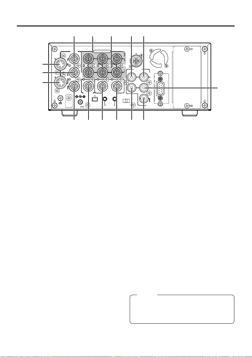
Page 18
NAMES AND FUNCTIONS
OF PARTS
– Rear panel – (continued)
COMPONENT
Y
SYNC IN
B-YR-Y
IN OUT
TIME CODE
IN OUT
DV
SERIAL
IN/OUT
REMOTE
^ ( ⁄ ¤ )‹
&
Y/C
SIGNAL
GND
MONITOR
LINE
OUT
OUT
*
VIDEO
IN
DC12V
^ DC power input terminal (2-PIN)
This terminal is for inputting DC 12 V. Connect
the DC power cord of the supplied AC adapter.
Memo
● When power is supplied to this terminal, the
OPERATE indicator located on the front panel
lights up. (The indicator turns red when BRDV6000 is in the OPERATE OFF state)
● Whether to set BR-DV6000 to enter the OPERATE ON mode or OPERATE OFF mode
when power is supplied to the terminal can
be selected with DC IN MODE in the SYSTEM (2/2) Menu screen.
● If the ) TIMER switch on the rear panel is
set to “REC” or “PLAY”, recording or playback
will be automatically started when power is
supplied to the terminal. (Timer recording/
playback)
& [SIGNAL GND] terminal
This is the grounding terminal for signals.
* DC power cord clamp
Use this clamp to fasten the DC power cord.
( [DV IN/OUT] terminal
This is the input/output terminal for IEEE1394compliant digital signals. It is for connecting to
video equipment with a DV terminal.
•To enable signal input via this terminal, set
the INPUT SELECT switch located on the
front panel to “DV”.
• Signals that come from this terminal are output regardless of the setting of the INPUT
SELECT switch.
• If REPLICATION of the SYSTEM (2/2) Menu
is set to DV, the REC command is output from
this terminal when BR-DV6000 begins playback. (REPLICATION mode)
• Set PB/DV IN in the SYSTEM(2/2) Menu
screen according to the signal format to be
input to this terminal. (NTSC or PAL)
18
IN
OUT
CH 1/3 CH 2/4
OFF
REC PLAY
TIMER
REMOTE2
AUDIO
IN
OUT
MONITOR
OUT
REMOTE1
) [TIMER] recording/playback
switch
This switch is for setting BR-DV6000 to start
timer recording or timer playback when power
is supplied to the ^ DC power input terminal
according to an external timer.
OFF : No timer recording or timer playback.
REC : When power is supplied, BR-DV6000
starts recording automatically.
(Timer recording)
PLAY : When power is supplied, BR-DV6000
starts playback automatically.
(Timer playback)
Memo
● If the TIMER switch is set to “REC” or “PLAY”,
BR-DV6000 automatically enters the OPERATE ON mode upon DC power on even when
DC IN MODE in the SYSTEM (2/2) Menu
screen is set to “OPE OFF”.
⁄ [SERIAL REMOTE IN] terminal
(mini jack)
This terminal is for connecting to the serial remote controller RM-G30 (sold separately).
To operate BR-DV6000 with this terminal, perform the following settings.
• Set REMOTE SEL SER in the REMOTE
(1/2) Menu screen to “ON” or “LOC+REM.”
ON : When the 4 REMOTE / LOCAL
LOC+REM: This terminal is effective regardless
Memo
● To use this terminal as the foot switch input,
set FOOT SW in the REMOTE (2/2) Menu
screen. (☞ Page 77)
switch on the front panel is set to
“REMOTE”, this terminal becomes
effective.
of the setting of the 4 REMOTE /
LOCAL switch on the front panel.
›
fi
Page 19

¤ [SERIAL REMOTE OUT] terminal
(mini jack)
• This terminal is for direct through-output of
serial commands of the serial remote input
terminal. (Only with OPERATE ON)
• If REPLICATION of the SYSTEM (2/2) Menu
screen is set to SERIAL, this terminal outputs REC commands when BR-DV6000 begins playback. (REPLICATION mode)Use this
function to connect BR-DV6000 to a dubbing
device for dubbing its playback video or playback sound.
‹
[REMOTE 1] RS-422A terminal
(D-SUB 9-PIN)
This terminal is for connecting to an RS-422A
serial interface-compatible editing remote controller (e.g. RM-G820).
With this terminal, BR-DV6000 can be used as
a player or recorder of an editing system.
To operate BR-DV6000 with RS-422A, perform
the following settings.
• Set REMOTE SEL 9-PIN in the REMOTE (1/
2) Menu screen to “ON”.
• Set the 4 REMOTE / LOCAL switch on the
front panel to “REMOTE”.
Memo
● Use screws, of the inch, not metric, system,
for fastening the connectors.
● This part can be replaced by the RS-232C
serial interface board SA-K46U (sold separately).
Consult your JVC authorized service agent
for such replacements.
› [REMOTE 2] JVC Bus terminal
(12-PIN)
This terminal is for connecting to the JVC bus
interface-compatible editing remote controller
(RM-G800, RM-G805).
With this terminal, BR-DV6000 can be used as
a player or recorder of an editing system.
To operate BR-DV6000 with this terminal, perform the following settings.
• Set REMOTE SEL JVC in the REMOTE
(1/2) Menu screen to “ON”.
• Set the 4 REMOTE / LOCAL switch on the
front panel to “REMOTE”.
fi Slot cover for an optional board
This cover can be removed to install any of the
following optional boards.
• SA-DV6000 network board
• SA-X61U AUDIO XLR IN board (2ch)
• SA-X62U AUDIO XLR OUT board (2ch)
Memo
● With the SA-X61U AUDIO XLR IN board installed, whether sound signals are input to
the XLR IN terminal or the AUDIO IN terminal can be selected with AUDIO INPUT SEL
in the AUDIO MENU. If the MIC terminal is in
use, the MIC terminal precedes.
● With the SA-X62U AUDIO XLR OUT board
installed, the audio channel to which signals
are output can be selected with the AUDIO
OUTPUT switch.
19
Page 20
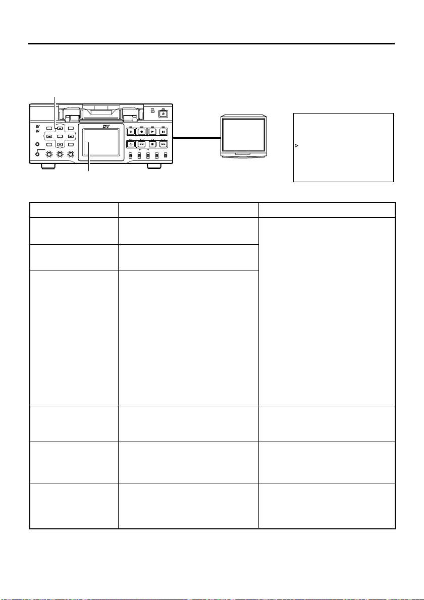
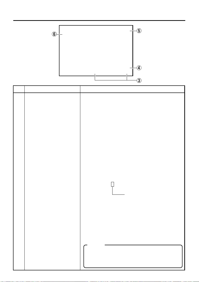
ON-SCREEN DISPLAY – On-screen display –
Besides E-E images and playback images, the monitor connected to the VIDEO MONITOR OUT
terminal provides the following on-screen information. Press the DISPLAY button to display the
same information on the LCD screen of BR-DV6000.
DISP button
Monitor
Mini
MIC
MENU RESET
DISP
SEARCH–
SET SEARCH+
BLANK CUE UP
HOLD
PHONES REC LEVEL
CH-1/3 CH-2/4
PROFESSIONAL
BR-DV6000
REC
A.DUB
REW STOP FF
EJECT
AUDIO INPUT
COUNTER
MONITOR OUTPUT REMOTE
CTL L
CH-1/2
TC
MIX
R
CH-3/4
UB
MIX
OPERATE
PLAY PAUSE
SELECT
DV
LINE
Y/C
(CPN)
VIDEO
MONITOR
OUTPUT
LOCAL
LCD screen
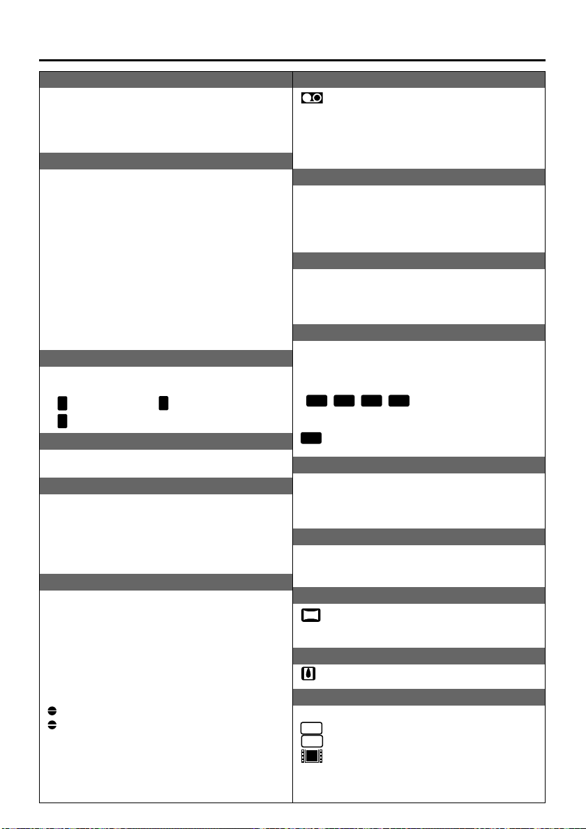
On-screen display Description Operation
Status display
Event display
Alarm display
Warning display
Menu display
Multi Cue-up screen
Displays the setting status of the VCR
operation mode, date/time, counter.
Displays the operating status of blank
search, index recording/search.
Displays error/alarm messages for incorrect operation or improper condition of BR-DV6000.
When an error occurred with the VCR,
it displays warnings with the relevant
error codes. (☞ Page 98)
Displays the menu setting screen.
(☞ Page 69)
Displays the Multi Cue-up screen for
registering or selecting cue-up
(searching) point. (☞ Page 54)
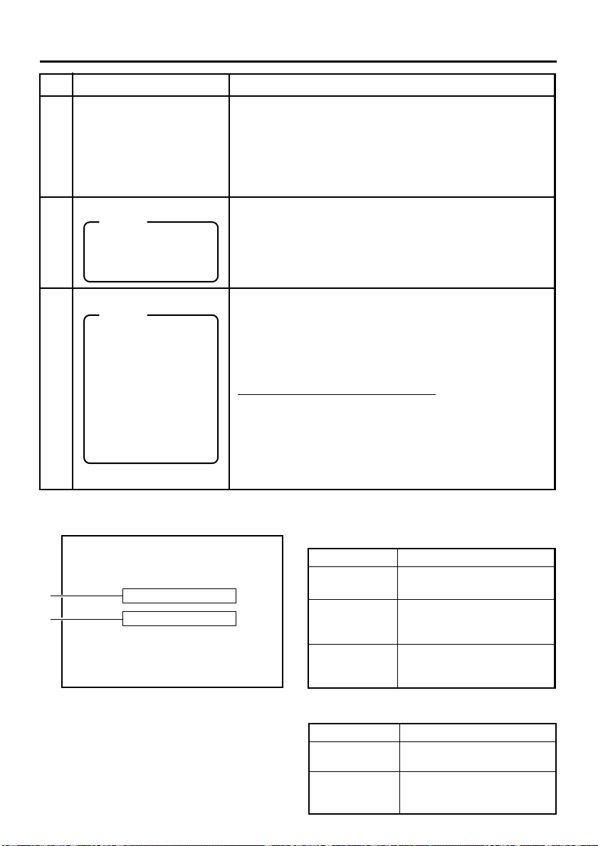
Settings can be performed with DISPLAY in the DISPLAY (1/2) Menu
screen.
ON : Always display. According
AUTO : It displays for about 4 sec-
OFF : No on-screen display. The
Display on the LCD
The on-screen display changes
whenever the DISPLAY button is
pressed.
(☞ Page 26)
It is displayed automatically when an
error with the VCR occurred.
When BR-DV6000 enters the STOP/
STILL mode or no cassette tape is
loaded, the menu is displayed when
the MENU button is pressed.
When BR-DV6000 enters the STOP,
STILL or PLAY mode, press the Cueup button to display the Multi Cueup screen.
DISPLAY (1/2) Menu screen
–––DISPLAY[1 / 2 ] –––
LCD BRI GHTNESS 0
LCD CHROMA 0
LCD CONTRAST 0
LCD AUTO OFF OFF
DISPLAY ON
COUNT ER POS I . LOWER - R
NEXT P AGE
PAGE BACK
to each event or error, the
event and alarm displays
are shown for about 3 seconds.
onds during mode
changes.
alarm display is shown according to errors, which
occurred.
20
Page 21
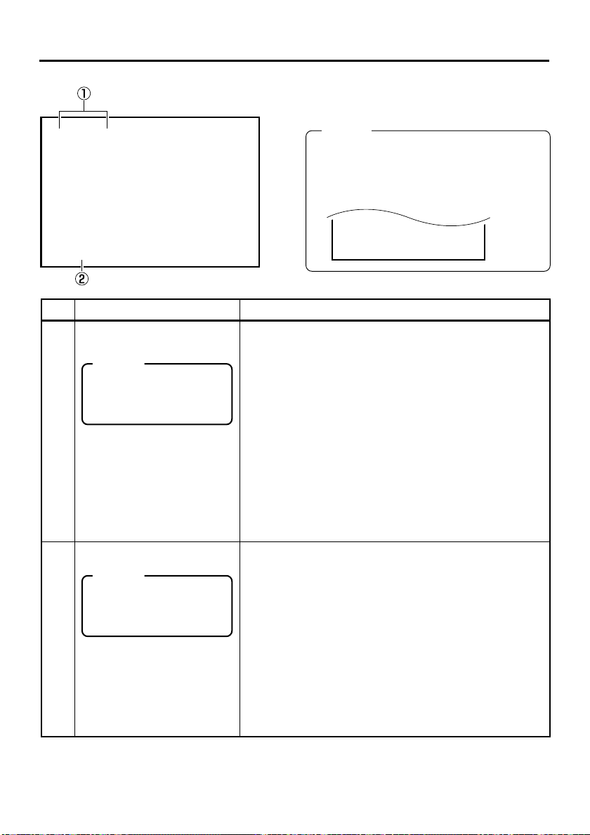
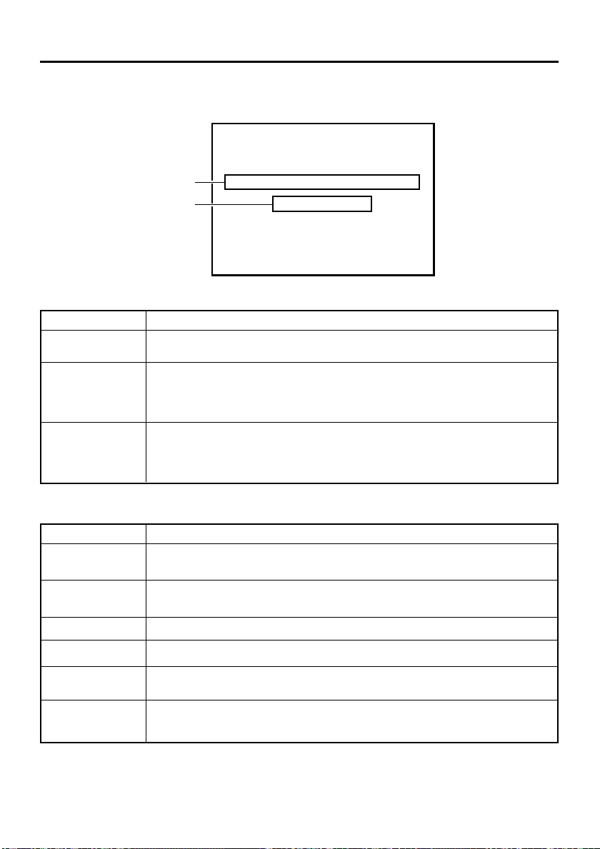
ON-SCREEN DISPLAY – Status display –
03/ 04 / 03 STANDBY-OFF
11: 20 : 00 TCR 02:00:00:00
03/ 04 / 03 11 :20:00
Status display: It displays the current settings and operating status.
32K CH–1/2 0SP mi n00
ASSEM
W
ARNING 7001
DRUM MOTOR FA I LURE
REC I NH I B I T
-
03/ 04/ 03 STANDBY
11: 20: 00 TCR 02:00:00:00
OFF
Memo
● With the DATE REC function in use, the last
line is fixed to the date/time display. The information displayed on the last line moves to
the line above. (DATE REC function: ☞ Page
81)
No. Item Description
Sampling frequency/audio
1
output CH
Memo
If the counter display position
is set to the upper left, this
item will be displayed on the
lower right.
Date/time
2
Memo
If the display position of the
counter is set to the lower
left, this item will be displayed on the lower right.
• Sampling frequency
During recording, the setting value of AUDIO MODE in the
AUDIO Menu screen is displayed (32k or 48k).
During playback, the sampling frequency of the sound re-
corded on the tape is displayed (32k, 48k, 44.1k).
During DV signal input, the sampling frequency of the sound
input is displayed.
• A.LOCK
Lights up when the video and audio sampling clocks (at
48kHz) are synchronized in the PLAYBACK mode.
Always lights up in the RECORDING mode and EE mode.
•Audio output channel
During playback, the audio channel output from the AUDIO
OUT terminal is displayed (CH1/2, CH3/4, MIX). (only in
32k mode)
• With AUDIO INFO. in the DISPLAY Menu screen, whether
to display this item can be selected.
• It displays the date (MM/DD/YY) and time (HR:MM:SS).
• When the unit is in the RECORDING or STOP mode, it
displays the data of the built-in clock.
• During playback, fast-forwarding or rewinding, the data recorded on the tape is displayed.
• During DV signal recording, the data from the DV terminal
is displayed. If the REC button is pressed in the STOP mode,
the input data from the DV terminal will be displayed.
• The style for displaying the date and time can be selected
with DATE STYLE and TIME STYLE in the DISPLAY Menu
screen.
• Whether to display date/time and the type of display can be
selected with TIME/DATE in the DISPLAY Menu screen.
• When the data/time is not set or when a tape is played with
no date/time data recorded, “– –” will be displayed.
21
Page 22
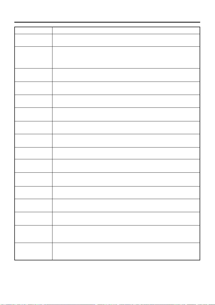
ON-SCREEN DISPLAY – Status display – (continued)
32K CH–1/2 0SP mi n00
ASSEM
W
ARNING 7001
DRUM MOTOR FA I LURE
REC I NH I B I T
03/ 04/ 03 STANDBY
11: 20: 00 TCR 02:00:00:00
-
OFF
No. Item Description
Counter display Displays the CTR counter, time code or user’s bit. The dis-
3
played contents can be selected using the COUNTER switch.
• CTL counter: It will be displayed if the COUNTER switch is
set to CTL. The counter shows a 7-digit
number (hour, minute, second and frame) with
+ or – and “CTL” at the beginning, e.g., CTL9:30:20:10
• Time code : It will be displayed if the COUNTER switch is
set to TC. The time code shows an 8-digit
number (hour, minute, second and frame).
At playback, the time codes recorded on the
tape are displayed.
The prefix indicates the time code mode.
TCG : Time code generator data
TCR : Time code reader data
DTCG : Time code data received from the DV IN / OUT
terminal
ETCG : External time code generator data
Depending on the framing mode, the symbols for the seconds and frames are different (only for NTSC).
00 : 00 : 00 : 00
Dot (.) for the drop frame mode
¥ Colon (:) for the non-drop frame mode
• User’s bit : it will be displayed if the COUNTER switch is
set to UB.
The user’s bit is an 8-digit number (each digit
is a number or character from 0 – F).
The prefix indicates the user’s bit mode.
UBG : User’s bit generator data
UBR : User’s bit reader data
DUBG : User’s bit reader data received from the DV IN /
OUT terminal
EUBG : External user’s bit generator data
Memo
● The position of the counter display can be changed with
COUNTER POSI in the DISPLAY Menu screen.
● The counter display can be turned on/off with TIME
CODE in the DISPLAY Menu screen.
22
Page 23
ON-SCREEN DISPLAY – Status/Event display –
No. Item Description
VCR operation mode
4
Remaining tape
5
6
Memo
If the counter display position is set to the upper
right, this item will be displayed on the lower right.
Edit mode display
Memo
● With the counter display shown on the top
left, this display appears on the bottom
right.
● In the 48 k audio mode,
insert editing is not
possible in the following cases.
INS A1, INS A2, INS
VA1, INS VA2
Event display : When certain functions are in use, it is displayed at the following posi-
tions (with the DISPLAY mode ON or AUTO).
32K CH–1/2 0SP mi n00
A
B
03/ 04/ 03 STANDBY
11: 20: 00 TCR 02:00:00:00
BLANK SEARCH
INDEX DETECTED
Displays the VCR operation mode, including:
PLAY, EJECT, FF, REW, STANDBY-ON, STANDBY-OFF, STILL,
REC, REC PAUSE, A. DUB, A. DUB PAUSE, ASSEM EDIT, INSERT
EDIT, SHTL (shuttle search), JOG, BLANK SRH (blank search),
NO CASSETTE (cassette tape not loaded), OPERATE OFF.
For SHTL and JOG, the speed is also displayed.
• The display can be turned on/off with VTR MODE in the DISPLAY
Menu screen.
Displays the remaining time of tape (minutes).
Not displayed when the remaining time is being confirmed.
• The display can be turned on/off with TAPE REMAIN in the DISPLAY Menu screen.
• The SP display disappears when a DVCAM cassette tape is being played back.
• This remaining tape time display is only for reference.
Displays the edit mode selected, e.g., by using the edit mode controller.
• ASSEM :Assemble editing
• INS V : Video insert editing
• INS A :Audio insert editing (Audio: both CH 1 and CH 2)
• INS VA : Video, audio insert editing (Audio: both CH 1 and
• INS VA : Video/Audio insert editing
• INS TC : Time code insert editing (Time code only)
CH 2)
Insert editing in the 32 k audio mode
• INS A12 :CH1, CH2 audio
• INS A34 :CH3, CH4 audio
• INS VA12:Video & CH1, CH2 audio
• INS VA34:Video & CH3, CH4 audio
• INS A :CH1 to CH4 audio
• INS VA : Video & CH1 to CH4 audio
The display can be turned on/off with EDIT INFO in the DISPLAY
Menu screen.
● “A” display: displayed during operation
Display Description
Blank search in progress.
Index search in progress.
The number indicates the index
search position.
When an index has been specified on the tape during recording.
-
OFF
BLANK
SEARCH
INDEX +1
INDEX MARK
● “B” display: displayed for about 3 seconds
Display Description
INDEX
DETECTED
VIDEO END
DETECTED
An index has been detected
during index repeat operation.
The video end has been detected during end repeat operation.
23
Page 24
ON-SCREEN DISPLAY – Alarm display –
Alarm display: An alarm message is displayed at the following positions when there has
been an operation error or when BR-DV6000 is not in good condition,
e.g., dirty head.
32K CH–1/2 0SP mi n00
A
B
● “A” display : The state of BR-DV6000 is displayed. It continues to be displayed until the error state is
corrected. This display is not affected by the setting of the display mode.
HEAD CLEANING REQUIRED!
NO DV S I GNA L
-
03/ 04/ 03 STANDBY
11: 20: 00 TCR 02:00:00:00
OFF
Display Description
LOW VOLTAGE
HEAD CLEANING REQUIRED!
OVERHEATING!
The voltage of the DC power source is low. If the operation continues, it enters
the Operate OFF mode.
The video head is dirty. Clean it with the head-cleaning tape exclusively for BRDV6000. (☞ Page 8)
If the head is clogged, it is detected in the PLAYBACK mode and this message
is displayed.
The temperature inside BR-DV6000 has exceeded the stated value.
Disconnect the power and place it at a cool place. If this message is displayed
again, BR-DV6000 could be defective.
Consult your JVC-authorized service agent.
● “B” display : Messages for incorrect operation are displayed for about 3 seconds.
They are displayed when the DISPLAY mode is ON or AUTO.
Display Description
INVALID TAPE!
LP TAPE!
NO DV SIGNAL
COPY INHIBIT
REC INHIBIT
REC INHIBIT
(NTSC/PAL)
24
Data tape for PCs or DVC PRO tape is used.
The cassette tape will be automatically ejected.
The user attempted to play back a tape recorded in the LP mode.
BR-DV6000 cannot record or play in the LP mode.
The user attempted to record without DV signal input.
The user attempted to record copy-guarded signals.
The user attempted to record on a tape that is not ready for recording (the rear
switch is set to SAVE).
The user attempted to record analog signals when PB/DV IN in the SYSTEM
(2/2) Menu is set to PAL.
Page 25
Display Description
A. DUB INHIBIT
(REC TAB)
A. DUB INHIBIT
(48 K)
A. DUB INHIBIT
(LP)
A. DUB INHIBIT
(BLANK)
A. DUB INHIBIT
(DV)
A. DUB INHIBIT
(NTSC/PAL)
A. DUB INHIBIT
(DVCAM)
EDIT INHIBIT
(REC TAB)
EDIT INHIBIT
(LP)
EDIT INHIBIT
(BLANK)
EDIT INHIBIT
(NTSC/PAL)
EDIT INHIBIT
(DV CAM)
EDIT INHIBIT
(AUDIO)
EDIT INHIBIT
(DV TC INS)
DV EE INHIBIT
The user attempted to perform audio dubbing on a tape that is not ready for
recording (the rear switch is set to SAVE).
This message is displayed when audio dubbing is attempted under the following
conditions.
• AUDIO MODE of the AUDIO Menu screen is set to 48 K.
• The tape is recorded with a sampling frequency of 48kHz
The user attempted to perform audio dubbing on a tape recorded in the LP
mode.
The user attempted to perform audio dubbing of a blank tape.
The user attempted to perform audio dubbing during DV signal input (with the
INPUT SELECT switch set to “DV”).
The user attempted audio dubbing when PB/DV IN in the SYSTEM (2/2) Menu
screen is set to PAL.
The user attempted to perform audio dubbing on a DVCAM format tape.
The user attempted to edit a tape that cannot be recorded (with the rear switch
set to “SAVE”).
The user attempted to edit a tape recorded in the LP mode.
The user attempted to insert-edit an unrecorded part of a tape.
The user attempted editing when PB/DV IN in the SYSTEM (2/2) Menu screen is
set to PAL.
The user attempted to edit a tape recorded in the DVCAM format.
The user attempted editing in an audio combination that cannot be edited.
The user attempted time-code insert-editing during DV signal input.
This message is displayed when the REC button is pressed during playback
with the INPUT SELECT switch set to DV.
(EE check is not allowed during DV input.)
OPERATION
LOCK
This message is displayed when an operation button is pressed with OPERATION LOCK enabled. To enable OPERATION LOCK, set OPERATION LOCK in
the SYSTEM (2/2) Menu screen to ON.
25
Page 26
2
1
4
5
8
9
ON-SCREEN DISPLAY – LCD display –
There are two display modes for the status display on the LCD of the unit.
• Same character display mode as the monitor output
• LCD display mode (enlarged display)
DISPLAY button
OPERATE
REC
PLAY PAUSE
Mini
MIC
MENU RESET
DISP
SEARCH–
SET
BLANK CUE UP
HOLD
PHONES REC LEVEL
CH-1/3 CH-2/4
SEARCH+
PROFESSIONAL
BR-DV6000
A.DUB
REW STOP FF
EJECT
COUNTER
MONITOR OUTPUT REMOTE
CTL L
TC
MIX
R
UB
AUDIO INPUT
CH-1/2
DV
MIX
LINE
CH-3/4
Y/C
(CPN)
SELECT
LCD
Memo
● With LCD AUTO OFF in the DISPLAY Menu screen, the LCD display can be set to disappear if it
continues to be on for a certain time.
When the display goes off automatically, press any button to return to the original display mode.
● The LCD display area is smaller compared with the one for the actual images.
LCD display mode (enlarged display)
6!
1
The LCD display mode changes in the following sequence
whenever the DISPLAY button is pressed (with DISPLAY
of the DISPLAY Menu screen set to ON or AUTO).
Enlarged
LOCAL
character display
No
display
Image
display
Image/enlarged
character display
Image/
character display
CH1/3
48k
L
CH2/4
NDF
T
C
FREE
PLAY
12H34M34S10
SP222
01/02/03
AM
01:23:45 INS
0@#$&
1 Audio output channel display
It displays the setting status of the AUDIO OUTPUT
switch on the front panel.
Top (CH 1 /3 AUDIO OUT): CH 1, CH 3, CH 1 /3
Bottom (CH 2 /4 AUDIO OUT): CH 2, CH 4, CH 2 /4
Audio sampling frequency display
2
• During recording, it displays the setting status of AU-
DIO MODE of the AUDIO Menu screen.(48k or 32k)
• During playback, the audio mode of the tape is dis-
played (48k, 32k, or 44.1k)
•L: Displayed during AUDIO LOCK.
26
OVER
min
W
Y/CVASYNC
dB010203040
OVER
e
CF
r
3
7
F
^
*
%
3 Audio level meter display
It displays the input sound level during recording or in
the STOP mode, and the playback sound level during
playback.
The reference recording level of BR-DV6000 is –20dB.
•For playing a tape recorded with a home-use DV machine with a reference level of –12 dB, set AUDIO OUT
LEVEL to –12 dB.
Page 27
4 Drop/Non-drop display (for NTSC only)
Displays the framing mode of the time code.
NDF : Non-drop frame
DF : Drop frame
PA L: Displays when PB/DV IN in the SYSTEM (2/2)
Menu screen is set to PAL.
5 Time code mode display
Displays the time code mode set in the TC/UB/CLOCK
Menu screen.
REGN : Regeneration mode
RRUN : REC RUN preset mode
FREE : FREE RUN preset mode
EXT : This is displayed when time codes are input to
the TIME CODE IN terminal (with TCG
SOURCE set to EXTERNAL).
It blinks when no time code is input or when the
phase of an external time code is not locked
with the phase of the video signal.
DUPL : This is displayed when TC DUPLICATE is set
to AUTO or NON DROP.
(Enter the time code of the DV terminal.)
6 Counter mode
The counter mode selected with the COUNTER switch
on the front panel is displayed.
C
: CTL counter
T
L
: User’s bit
U
B
: Time code
T
C
7 Counter display
• The CTL counter is displayed as a 7-digit number with + or –.
The time code/user’s bit is displayed as an 8-digit number.
8 VCR mode display
Displays the operation mode of the VCR.
The reservation of mode is displayed in blinking light.
NOCAS (no cassette tape), EJECT, STBON (standbyon), STBOF (standby-off), PLAY, STILL, FF, REW, SHTL,
ADUBP (audio dubbing pause), REC, RECP (recording
pause), INSERT, ASSEM, OPOFF (operate off)
9 VCR mode graphic display
c : Eject
L : Stop
: : Play
J :Still
Z : FF/Forward search
+ : REW/ Reverse search:
a : Record
aJ : Recording pause
:Audio dubbing
J :Audio dubbing pause
0 Tape symbol display
: This symbol is displayed when a cassette tape is
loaded.
It blinks during loading or ejecting of a cassette
tape.
If the rear switch of the cassette tape is set to
SAVE, it is displayed in yellow.
! Remaining tape time display
Displays the remaining time (minutes). Blinks if the remaining time is less than 4 minutes.
Not displayed when the remaining time is being confirmed. SP will not be displayed when a DVCAM cassette tape is being played back.
@ Time/Date display
The data of the built-in clock will be displayed during recording or in the STOP mode. Displays the data of the
tape during playback.
If the date/time is not set up, “– – –” is displayed.
# Input video signal display
Displays the input video signal selected with the INPUT
SELECT switch on the front panel.
Blinks if the selected signal is not input (LINE, Y/C, CPNT,
or DV).
LINE, Y/C, CPNT, DV
(
In the case of a copy-prohibiting signal, it will be displayed in yellow.
SYNC
: It is displayed when signals are input via the SYNC
IN terminal with EXTERNAL SYNC selected.
)
$ Editing mode display
The editing mode selected with the editing remote controller is displayed.
(ASSEM, INSV, INSA, INSVA, INS TC, INS VA12, INS
VA34, INS A12, INS A34)
% Timer display
r : It is displayed when the TIMER switch on the rear
panel is set to REC or PLAY.
REC: RED PLAY: GREEN
^ Wide screen ID signal display
: It will be displayed when a wide screen ID signal
W
exists in the input signal of the Y/C or DV terminal.
The data on the tape is displayed during playback.
& Condensation display
: It is displayed when condensation occurs.
* Option display
It is displayed when an option board is connected.
XLI
: SA-X61U connection
XLO
: SA-X62U connection
: SA-DV6000 connection
e
27
Page 28
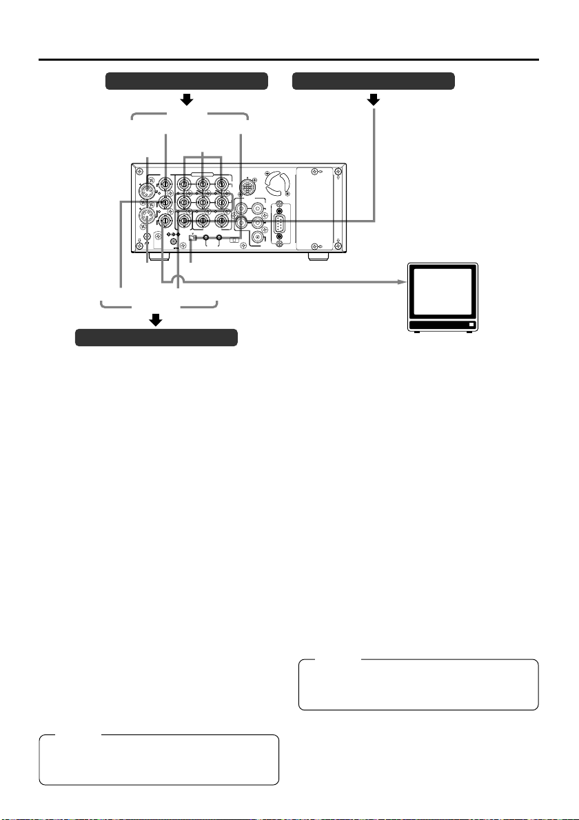
CONNECTION – Connecting video signals –
Video output, e.g., VCR Synchronization signal generator
Input
Composite
Composite
Y/C
LINE
Y/C
IN
OUT
MONITOR
OUT
SIGNAL
GND
Y/C
Component
VIDEO
Y
SYNC IN
DV
IN/OUT
DC12V
DV
Component
COMPONENT
B-YR-Y
IN OUT
TIME CODE
IN OUT
SERIAL
REMOTE
DV
IN
OUT
OFF
REC PLAY
TIMER
CH 1/3 CH 2/4
Output
Video output, e.g., VCR
Output signal
When BR-DV6000 enters the STOP, REC or
EDIT mode, the input signal (E-E image) is output. In the PLAYBACK mode (including the playback of the pre-roll part during editing), playback images are output.
However, in the edit mode with analog input,
signals cannot be output to the DV OUT terminal properly.
● Analog signal
• LINE OUT terminal (BNC): composite signal.
• Y/C OUT terminal (4-PIN): YC separate sig-
nal.
When a wide screen ID signal exists in the
video signal, the ID signal is output.
• COMPONENT OUT terminal (BNC3):
Component (Y/B-Y/R-Y) signals are output.
The output level is of ß cam (HIGH).
● Digital signal
•DV IN/OUT terminal: it outputs IEEE1394-
compliant digital video signals.
When a wide screen ID signal exists in the
video signal, the ID signal is output.
● Connection with a monitor TV
A monitor TV can be connected to the MONITOR OUT terminal. Besides the composite
video signals, it also displays the on-screen display for status or menu screen.
Memo
Set PB/DV IN in the SYSTEM (2/2) Menu
screen according to the signal format of the
tape to be played. (NTSC or PAL)
REMOTE2
AUDIO
IN
OUT
MONITOR
OUT
REMOTE1
MONITOR OUT (Composite)
Input signal
The input video signal is selected with the INPUT SELECT switch on the front panel. Set
VIDEO INPUT SEL in the VIDEO Menu screen
to select YC input or component input.
● Analog signal
• LINE IN terminal (BNC): composite signal
• Y/C IN terminal (4-PIN): YC separate signal
When a wide screen ID signal is being input,
the ID signal is recorded.
• COMPONENT IN terminal (BNC3):
The component (Y/B-Y/R-Y) signal.
The output level is of ß cam (HIGH).
● Digital signal
•DV IN/OUT terminal : IEEE1394-compliant
When a wide screen ID signal is being input,
the ID signal is recorded.
Set PB/DV IN in the SYSTEM (2/2) Menu
screen according to the signal format to be
input to the DV terminal. (NTSC or PAL).
Memo
Whether or not to enable SET UP for analog
I/O signals of signals can be selected with SET
UP in the VIDEO Menu screen (for NTSC only).
BB signal
SYNC IN
Monitor
digital video signals
are input.
28
Page 29
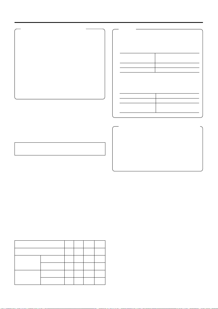
Caution on video signals
● If search images or video signals with a high
level of jitter are input, images or sound may
be distorted temporarily. Thus, input stable
signals, e.g., those having gone through a
TBC.
● A digital VCR requires that video signals for
recording be delivered from a stable source.
Video signals from an analog VCR must be
run through a TBS or TBC.
● When a component output is executed for
composite-input video, discoloration may occur on the left side of the screen. It is not a
defect.
Synchronization signal
In order to enhance the level of edit precision,
input synchronization signals to all the devices
of the editing system during editing.
For BR-DV6000, input external synchronization
signals into the SYNC IN terminal. For external
synchronization signals, use video signals of 1V
(p-p) or lower (e.g., black burst signals).
To edit DV signals, synchronization signal input is required.
Types of synchronization signal:
BR-DV6000 is operated based on one of the
following 3 types of synchronization signal.
• Synchronization signals produced by the synchronization signal generator inside the VCR
(INT)
• Video signals from the video signal input terminal (VIDEO)
• Synchronization signals from the SYNC IN
terminal (EXT)
Selection of synchronization signals:
Synchronization signals should be selected depending on whether external synchronization
input (SYNC IN) or video input (VIDEO IN) exists or on the SYNC SELECT Menu settings.
Synchronization signals are selected as shown
in the following table.
SYNC IN
VIDEO IN
Playback
EXTERNAL
AUTO
❈
❈
Record
❈
Playback
Record
The above can be selected with SYNC SELECT in the SYSTEM Menu screen.
No YesYe s N o
No YesNo Yes
INT
EXT
INT
INT
INT
VIDEO
INT
EXT
VIDEO
INT
INT
VIDEO
EXT
VIDEO
EXT
VIDEO
Memo
● During DV signal recording, the status of
synchronization signals will be as shown below regardless of the SYNC SELECT menu
settings.
SYNC IN terminal
signal
Input
No input
Synchronization
signals
EXT
DV
● Regardless of the setting of SYNC SELECT,
when a tape recorded in PAL is played back,
synchronization signals are as shown below.
SYNC IN terminal
PAL signal input
NTSC signal input or
No signal input
Synchronization signals
EXT
INT
Caution on synchronization signals
● For external synchronization signals, outputsignal phase adjustments cannot be performed. In addition, the sub carrier cannot be
locked.
● Plugging and unplugging of external synchronization signals or video input signals during
playback causes distortion of images and
sound for about 5 seconds.
29
Page 30
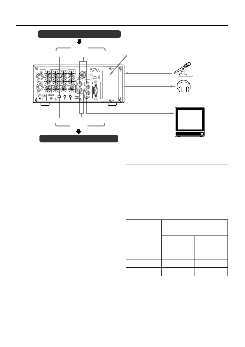
CONNECTION – Connecting audio signals –
Audio output of VCR
Input
B-YR-Y
TIME CODE
SERIAL
REMOTE
Analog audio
REMOTE2
IN
AUDIO
OUT
CH 1/3 CH 2/4
OFF
REC PLAY
TIMER
(2 channels)
IN
OUT
MONITOR
OUT
REMOTE1
DV
COMPONENT
VIDEO
LINE
Y/C
IN
Y
OUT
MONITOR
SIGNAL
GND
IN OUT
OUT
SYNC IN
IN OUT
DV
IN/OUT
DC12V
MONITOR OUT analog (monaural)
Analog audio (2 channels)
DV
Output
Audio input of VCR
Output signal
When BR-DV6000 is in the STOP, REC or EDIT
mode, signals (EE sound), which have been
input, are output.
During the PLAYBACK mode (including the
playback of the pre-roll part during editing), the
playback sound is output.
However, in the edit mode with analog input,
signals cannot be output to the DV OUT terminal properly.
● Analog signal
CH 1/3, CH 2/4 AUDIO terminal (RCA2).
There are analog audio terminals for 2 channels.
For the DV format, tracks are available for 4
channels (in the 32kHz audio mode).
• In the 32kHz mode, from which one of the 4
channels sound is output can be selected with
the AUDIO OUTPUT switch on the front
panel. (Refer to the table on the right.)
● Headphone terminal
Sound can be checked in stereo using a
headphone. The volume can be adjusted with
the PHONES switch on the front panel.
• The channel to be output from this terminal
in the 32kHz audio mode can be selected
with the AUDIO OUTPUT switch. (Refer to
the table on the right.)
Slot cover for optional board
Microphone
Monaural
Stereo
Headphone
Monitor
AUDIO OUTPUT switches and output
channels
In the following cases, the channels that receive
output from the AUDIO OUTPUT terminal vary
according to the setting of the AUDIO OUTPUT
switch. The table below shows the channels.
• During playback of tapes recorded in the 32kHz
audio mode.
• During audio dubbing.
• In the EE mode of DV input in the 32kHz audio
mode.
AUDIO
OUTPUT
switch
CH1/2
MIX
CH3/4
• In the 48kHz audio mode or during normal recording, output goes to CH1 and CH2 regardless of the setting of the switch.
AUDIO OUT terminal
CH1/3
CH2/4
(L)
CH1
CH1/3
CH3
CH2
CH2/4
CH4
(R)
30
Page 31

● Connecting to a monitor TV
A monitor TV can be connected to the AUDIO
MONITOR OUT terminal.
The sound output from the AUDIO MONITOR
OUT terminal is monaural.
• The volume is adjusted through the monitor
TV.
• The output channel can be selected with the
AUDIO MONITOR switch on the front panel
(Refer to the following table).
AUDIO MONITOR switches and output
channels of AUDIO OUTPUT/PHONES
In the following cases, the output channels from
the AUDIO MONITOR OUTPUT/PHONES terminal vary according to the setting of the AUDIO
MONITOR switch and the AUDIO OUTPUT switch.
The table below shows the channels.
• During playback of tapes recorded in the
32kHz audio mode.
• During audio dubbing.
• In the EE mode of DV input in the 32 kHz
audio mode.
AUDIO switch MONITOR OUT/
MONITOR
L
MIX
R
• In the 48kHz audio mode or during normal
recording, it outputs to CH1/2 channel (the
OUTPUT switch listed in the above table
shows the setting of CH1/2).
• When MIX is selected, the PHONES terminal outputs stereo sound.
OUTPUT
CH1/2
MIX
CH3/4
CH1/2
MIX
CH3/4
CH1/2
MIX
CH3/4
PHONES terminal
CH1
CH1/3
CH3
CH1/2
CH1/2/3/4
CH3/4
CH2
CH2/4
CH4
● Digital output
IEEE1394-compliant digital signals are output
from the DV IN/OUT terminal.
Input signal
● Analog signal
CH 1/3 AUDIO IN terminal. (RCA2)
There are analog input terminals for 2 channels. Recording cannot be performed to 4 channels at the same time. Sound from each terminal is usually recorded to CH1 and CH2.
To record to CH 3 and CH 4, set AUDIO MODE
of the AUDIO Menu screen to 32 k and record
it in the audio-dubbing mode. (☞ Page 44)
● Microphone input terminal
This terminal is for connecting to a monaural
microphone. The same sound is recorded on
the 2 channels.
Memo
● To record sound on the AUDIO IN terminal
and MIC terminal, set the INPUT SELECT
switch on the front panel to “LINE” or “Y/C
(CPN)”.
● If the AUDIO IN terminal and MIC terminal
are used at the same time, the MIC terminal
precedes.
● Digital input
IEEE1394-compliant digital signals are input
into the DV IN/OUT terminal.
•To enable audio input into this terminal, set
the INPUT SELECT switch to DV.
• The AUDIO MODE (48 K or 32 K) will be one
of input signals.
• During digital signal input, the recording level
cannot be adjusted.
Memo
● An input/output board (sold separately) of the
XLR connector can be installed in the optional
slot.
SA-X61U AUDIO XLR IN board
SA-X62U AUDIO XLR OUT board
These boards cannot be installed at the same
time.
● For BR-DV600 player, when the mode is
changed from STILL to PLAY, sound will be
muted for a while shortly after the audio output. Thereafter, it will resume as per normal.
(This does not occur with BR-DV600A.)
31
Page 32

IN
OUT
LAP
PLAYER
RECORDER
CONNECTION – Connecting to editing sytem –
BR-DV6000 is equipped with 2 remote terminals, for the JVC bus and RS-422A for editing purposes.
When a JVC bus-compatible editing remote controller is used:
For the editing remote controller, use RM-G800 or RM-G805.
Example: BR-DV6000 as player and recorder for cut editing of digital signals.
MonitorMonitor
VIDEO
MONITOR
Synchronized
VIDEO
MONITOR
signal generator
SYNC IN
COMPONENT
VIDEO
LINE
Y/C
IN
Y
OUT
MONITOR
SIGNAL
GND
IN OUT
OUT
SYNC IN
DV
IN/OUT
DC12V
B-YR-Y
TIME CODE
IN OUT
SERIAL
REMOTE
IN
OUT
OFF
REC PLAY
TIMER
REMOTE2
AUDIO
CH 1/3 CH 2/4
MONITOR
IN
OUT
OUT
DV DV
B.B. B.B.
AUDIO MONITOR
REMOTE1
DV cable (video/audio)
SYNC IN
COMPONENT
VIDEO
LINE
Y/C
IN
Y
OUT
MONITOR
SIGNAL
GND
IN OUT
OUT
SYNC IN
DV
IN/OUT
DC12V
B-YR-Y
TIME CODE
IN OUT
SERIAL
REMOTE
IN
OUT
OFF
REC PLAY
TIMER
REMOTE2
AUDIO
CH 1/3 CH 2/4
Remote cableRemote cable
Player Recorder
EDITING CONTROL UNIT RM-G800
HOUR MINUTE SECOND FRAME
COUNTER TC HOLD
CTL
TC
UB
PRESET
EDITMODE
GPI
MANUAL TAKE
SHIFT PREVIEW REVIEW
AUTO EDIT ALL STOP
Note
Before connecting the cables for remote ter-
ASSEM VIDEO/Hi-Fi AUD-1 AUD-2
REC REW PLAY STILL FF SEARCH
ENTRYMENU
CANCEL GOTO
ENTRY
IN OUT
RM-G800
/G805
Related VCRs
● VHS/S-VHS VCR
minals, ensure that the power to the VCR is
turned off.
REMOTE 2 (12-PIN)REMOTE 2 (12-PIN)
LAP
MENU SETSET
ON
COUNTER RESET
EJECT
OFF
STOP
PLAYER RECORDER
R
P
STILL
X-1 X1
REV FWD
No input/output of DV signals is possible.
BR-S800 + (SA-N50)
BR-S500 (player) + (SA-N50)
Remote extension cable
To extend the cables for the remote terminals,
use the extension cable VC-G8030U (3m) (sold
separately).
DV cable
Use VC-VDV204 (2 m, 4P-4P) or VC-VDV206
(2 m, 4P-6P) (sold separately).
● DV VCR
BR-DV600/A
Note
● If RM-G800 is to be used, check whether the (x)
mark is printed on the label at the bottom of the
unit.
If there is no (x) mark, modification is required.
Consult your JVC service agent.
● For the use of RM-G800/G805, there are certain regulations regarding Electro-Magnetic
Compatibility (EMC). Consult your JVC service
agent.
MONITOR
IN
OUT
OUT
AUDIO
MONITOR
REMOTE1
32
Page 33

When an RS-422A-compatible remote controller is used:
For the editing remote controller, use RM-G820.
Example: use BR-DV6000 as player and recorder for cut editing of analog signals.
MonitorMonitor
VIDEO
MONITOR
AUDIO
MONITOR
MONITOR
IN
OUT
OUT
Video signals
Audio signals
REMOTE1
VIDEO OUT
Player Recorder
Y/C
SIGNAL
SYNC IN
LINE
IN
OUT
MONITOR
OUT
GND
VIDEO
Y
SYNC IN
DC12V
AUDIO OUT
COMPONENT
IN
B-YR-Y
OUT
IN OUT
TIME CODE
IN OUT
OFF
REC PLAY
DV
TIMER
SERIAL
IN/OUT
REMOTE
B.B.
REMOTE2
AUDIO
CH 1/3 CH 2/4
REMOTE 1 (9-PIN)
B.B.
B.B.
VIDEO
MONITOR
VIDEO IN
VIDEO
LINE
Y/C
IN
OUT
MONITOR
OUT
SIGNAL
DC12V
GND
Remote cable
AUDIO IN
Y
SYNC IN
IN/OUT
COMPONENT
IN OUT
DV
B-YR-Y
TIME CODE
IN OUT
SERIAL
REMOTE
IN
OUT
OFF
REC PLAY
TIMER
REMOTE2
AUDIO
CH 1/3 CH 2/4
SYNC IN
REMOTE 1 (9-PIN)
AUDIO
MONITOR
IN
OUT
MONITOR
OUT
REMOTE1
SYNC IN
RM—G820
VIDEO
CANCEL
OUTINENTRY
EDITING CONTROL UNIT
IN OUT SERVO
IN
FRAME
HOUR MIN SEC
OUT
IN
OUT
PR
VITC
VITC
RESET
LTC
LTC
LAP
TOTAL
CTL
CTL
END
EVENT
V.SPEED
RIPPLE
RENUMBER
MAN.TAKELEARN
SPLIT
AUD-2
AUD-1
TC
+–
LAST
REC
ED
EE
IN
AUTO EDIT
GOTO REVIEW
ALL STOP
RECORDER
EJECT
REC REW FF STOP
STB OFF
SEARCHPAUSE
PLAY
/STILL
OUT
STILL
X1
X-1
MAX
MIN
REV
FWD
MONITOR
RECORDER
Synchronized signal generator
LAP
IN OUT SERVO LAP
FRAME
HOUR MIN SEC
LAP
PLAYER
EJECT
REC REW FF STOP
X-1
EVENT No.
BUMP
V.SPEED
ON
OFF
A.SPLIT
DURATION
PREROLL
7
5
RESET
3
P
CONTINUE
START
MENU
AUX
ASSEM
STB OFF
SPLIT
SEARCHPAUSE
PLAY
/STILL
STILL
X1
MAX
PREVIEW
SHIFT
MIN
REV
FWD
MONITOR
PLAYER
RM-G820
To fasten the connector of the remote
cable to the REMOTE 1 terminal, use a
screw of the inch, not metric, system.
Related VCRs
● VHS/S-VHS VCR
BR-S800 (equipped with SA-K26, SA-R50,
SA-N50)
In order to enhance the level of editing
precision, input synchronization signals (black burst signals) to all devices.
(
☞ Page 29)
When BR-DV3000 is to be used as the player,
input as synchronization signals the composite
signals or the Y signals of the YC signals of BRDV3000 to the SYNC IN terminal of BR-DV6000.
BR-S822 (equipped with SA-T22)
* No input/output of DV signals is possible.
● D-9 (digital S) VCR
BR-D80, BR-D85, BR-D750
(Only analog signals)
● DV VCR
BR-DV3000 (player only)
BR-DV600/A (player only)
For information on settings and other points on the operation of BR-DV6000 with
an editing system, refer to pages 64 – 68.
33
Page 34

CONNECTION – Connection with serial remote terminals –
The following describes examples of serial remote terminal connection.
To use the serial remote terminals, set REMOTE SEL SER of the REMOTE (1/2) Menu screen
to “ON” or “LOC+REM.” (
Operate BR-DV6000 with the wired remote controller RM-G30 (sold separately)
COMPONENT
VIDEO
LINE
Y/C
IN
OUT
MONITOR
OUT
SIGNAL
GND
B-YR-Y
Y
IN OUT
SYNC IN
TIME CODE
IN OUT
DV
SERIAL
IN/OUT
REMOTE
DC12V
SERIAL IN
Start/stop recording with an external switch, e.g., a foot switch.
COMPONENT
VIDEO
LINE
Y/C
IN
OUT
MONITOR
OUT
SIGNAL
GND
B-YR-Y
Y
IN OUT
SYNC IN
TIME CODE
IN OUT
DV
SERIAL
IN/OUT
REMOTE
DC12V
SERIAL IN
Foot
switch
Dubbing of playback images or sound with other machines using the SERIAL RE-
MOTE OUT terminal.
When BR-DV6000 is in the playback mode, the REC command can be output from the SERIAL
REMOTE OUT terminal (REPLICATION function). With this function, a tape loaded in BR-DV6000
can be dubbed on another unit. For details, refer to ☞ Page 57.
BR-DV6000 can be used as a master or dubbing unit.
● Dubbing with 1 VCR.
(Master unit) BR-DV6000
COMPONENT
VIDEO
LINE
Y/C
IN
OUT
MONITOR
OUT
SIGNAL
DC12V
GND
SERIAL OUT
Y
SYNC IN
IN OUT
TIME CODE
IN OUT
DV
IN/OUT
IN
B-YR-Y
OUT
CH 1/3 CH 2/4
OFF
REC PLAY
TIMER
SERIAL
REMOTE
● Dubbing with multiple VCRs (Up to 50 VCRs can be controlled comprehensively.)
(Master unit) BR-DV6000
COMPONENT
IN OUT
TIME CODE
IN OUT
DV
IN/OUT
REMOTE2
IN
B-YR-Y
AUDIO
OUT
CH 1/3 CH 2/4
OFF
REC PLAY
TIMER
SERIAL
REMOTE
VIDEO
LINE
Y/C
IN
Y
OUT
MONITOR
OUT
SYNC IN
SIGNAL
DC12V
GND
SERIAL OUT
34
REMOTE2
IN
AUDIO
OUT
CH 1/3 CH 2/4
IN
OUT
OFF
REC PLAY
MONITOR
TIMER
OUT
SERIAL OUT
REMOTE2
IN
AUDIO
OUT
CH 1/3 CH 2/4
IN
OUT
OFF
REC PLAY
MONITOR
TIMER
OUT
SERIAL OUT
REMOTE2
AUDIO
IN
OUT
MONITOR
OUT
REMOTE1
REC command
IN
OUT
MONITOR
OUT
REMOTE1
☞ Page 75)
REMOTE1
Through-output
RM-G30
REMOTE1
Through-output
Video
Sound
Video
Sound
Connect the wired remote controller RM-G30 to
the SERIAL REMOTE IN terminal.
The commands of the SERIAL REMOTE IN terminal is through-output from the SERIAL REMOTE
OUT terminal. (Only with OPERATE ON)
Multiple VCRs can be operated with RM-G30 by
series connection of the SERIAL REMOTE IN/OUT
terminals.
Connect an external switch, e.g., a foot switch, to
the SERIAL REMOTE IN terminal.
The format of the input signals can be selected
with FOOT SW in the REMOTE (2/2) Menu screen.
(☞ Page 46)
(Dubbing unit) VCR
with a SERIAL terminal
SERIAL
terminal
Signal distributor
SERIAL
IN OUT IN
❈
Dubbing unit: VCR with SERIAL IN and OUT terminals
DV: BR-DV6000
Memo
If REPLICATION of the SYSTEM
(2/2) Menu screen is set to DV, the
REC command is output from the
DV terminal.
SERIAL
Page 35

CONNECTION – Connecting the AC adapter –
Connect the supplied AC adaptor to BR-DV6000.
Screw
Supplied AC adaptor
Clamp
Supplied power
cord
DC cord
OPERATE indicator
OPERATE button
SELECT
LOCAL
NAL
V6000
REC
A.DUB
REW STOP FF
EJECT
AUDIO INPUT
COUNTER
MONITOR OUTPUT REMOTE
CTL L
CH-1/2
TC
MIX
MIX
R
CH-3/4
UB
OPERATE
PLAY PAUSE
DV
LINE
Y/C
(CPN)
Memo
● Even in the OPERATE OFF mode, a small
amount of electricity will still flow into the unit.
● When the unit is in the OPERATE OFF mode,
no operation can be performed except that
of the OPERATE buttons and cassette loading/ejecting.
COMPONENT
VIDEO
LINE
Y/C
IN
Y
OUT
SIGNAL
GND
MONITOR
OUT
IN OUT
SYNC IN
TIME CODE
IN OUT
DV
IN/OUT
DC12V
SERIAL
REMOTE
REMOTE2
IN
B-YR-Y
OUT
OFF
REC PLAY
TIMER
AUDIO
CH 1/3 CH 2/4
MONITOR
IN
OUT
OUT
REMOTE1
DC IN
terminal
TIMER switch
Before connecting the AC adaptor, en-
sure that the TIMER switch is set to
“OFF”. (Refer to “Notes” below.)
1.
Connect the DC cord of the AC adapter to
the DC IN terminal of BR-DV6000.
2.
To prevent accidental disconnection of the
DC cord, fasten the DC cord with a clamp.
1Remove the screw and the clamp shown in
the above figure.
2Insert the DC cord into the clamp and fasten
the clamp unto the unit.
3.
Connect the supplied power cord to the AC
IN terminal of the AC adapter.
4.
Connect the power cord to the power outlet.
• BR-DV6000 is turned on and the OPERATE
indicator lights up in red.
(OPERATE OFF mode)
• If DC IN MODE of the SYSTEM (2/2) Menu
screen is set to “OPE ON”, the OPERATE indicator will light up in green.
(OPERATE ON mode)
Notes
LOW VOLTAGE
Alarm message
• Supply power to BR-DV6000 using the supplied AC adapter. Do
not use other power sources.
• Do not unplug the DC cord and/or the power cord during recording
or playback.
• If the supply voltage is low, an alarm display of “LOW VOLTAGE” is
shown.
• If the TIMER switch is set to REC or PLAY, recording or playback
begins when power is supplied to the DC IN terminal.
When the AC adapter is connected, ensure in particular that the
TIMER switch is not set to REC.
Set the TIMER switch to REC or PLAY only when an external timer
function is used.
35
Page 36

PREPARATION – Turning on/off the power –
Turning on the power
OPERATE indicator
OPERATE
button
SELECT
LOCAL
RESET
DISP
SET SEARCH+
BLANK CUE UP
REC LEVEL
CH-1/3 CH-2/4
PROFESSIONAL
BR-DV6000
A.DUB
REC
EJECT
REW STOP FF
AUDIO INPUT
COUNTER
MONITOR OUTPUT REMOTE
CTL L
CH-1/2
TC
MIX
R
CH-3/4
UB
MIX
OPERATE
PLAY PAUSE
DV
LINE
Y/C
(CPN)
Note
After the OPERATE button is pressed and BRDV6000 is turned on, if the green indicator
blinks or the monitor or the LCD displays “UNPLUG MAIN POWER, PLUG BACK IN AFTER
A WHILE”, unplug the power cord from the
power outlet, leave it for a while before turning
on the power again.
Press the OPERATE button when BR-
DV6000 is in the OPERATE OFF mode
(with the OPERATE indicator lit up in
red)
• The power is turned on and the OPERATE
indicator lights up in green. BR-DV6000 is
ready for operation. (OPERATE ON mode)
Memo
● In the OPERATE OFF mode, if a cassette
tape is inserted, the power is turned on and
BR-DV6000 goes into the OPERATE ON
mode.
● Whether BR-DV6000 goes into the OPERATE ON or OFF mode when the power is supplied to the DC IN terminal can be selected
with DC IN MODE in the SYSTEM (2/2) Menu
screen.
● If TIMER REC or TIMER PLAY is selected,
BR-DV6000 starts up in the OPERATE ON
mode regardless of the DC IN MODE Menu
settings. If a cassette tape is loaded, BRDV6000 starts recording or playback.
Turning off the power
Turn off BR-DV6000
1.
Press the OPERATE button.
• BR-DV6000 enters the OPERATE OFF mode and the OPERATE indicator lights up in red.
2.
If BR-DV6000 is not to be used for a long period of time, unplug the AC adapter.
To unplug the AC adapter, remove the power cord from the power outlet first.
36
Page 37

PREPARATION – Operation method (main unit/
remote controller) and operation lock mode –
Selecting the operating method (main unit/remote controller)
Whether to operate BR-DV6000 with its buttons or the remote
OPERATE
REC
PLAY PAUSE
PROFESSIONAL
BR-DV6000
A.DUB
REW STOP FF
EJECT
AUDIO INPUT
COUNTER
MONITOR OUTPUT REMOTE
CTL L
CH-1/2
TC
MIX
R
CH-3/4
UB
SELECT
DV
MIX
LINE
Y/C
(CPN)
REMOTE (1/2) Menu screen
———
REMOTE [ 1 / 2 ]
REMOTE SE L 9 P ON
REMOTE SE L SER ON
REMOTE SE L DV ON
REMOTE SE L JVC ON
REMOTE SE L NET ON
LOCAL FUNC T I ON STP + E J T
PREROLL 7SEC
NEXT PAGE
PAGE BACK
———
Memo
If the REMOTE/LOCAL
switch is set to REMOTE,
the buttons that can be operated by the main unit can
be selected with LOCAL
FUNCTION.
controller can be selected with the REMOTE/LOCAL switch.
Setting the REMOTE/LOCAL switch
•To operate with the buttons of BR-DV6000, set it to “LOCAL”.
LOCAL
•To operate BR-DV6000 with RS-422A or JVC-bus editing remote controller that is connected to the REMOTE 1 (9-PIN) or
REMOTE 2 (12-PIN) terminal, set it to “REMOTE”.
Memo
With the REMOTE/LOCAL switch set to REMOTE, the JVC bus
or RS-422A can be enabled using REMOTE SEL JVC or REMOTE SEL 9P in the REMOTE (1/2) Menu screen.
• The setting position of the REMOTE switch for operating BRDV6000 with the SERIAL REMOTE terminal can be selected
using REMOTE SEL SER in the REMOTE (1/2) Menu screen.
• The setting position of the REMOTE switch for operating BRDV6000 with the DV terminal can be selected at REMOTE SEL
DV in the REMOTE (1/2) Menu screen.
[☞ Page 75 “REMOTE (1/2) Menu screen”]
OPERATION LOCK mode
BR-DV6000 comes with an operation lock function to prevent unauthorized or incorrect operation.
In the OPERATION LOCK mode, the operation buttons and slide switches of BR-DV6000 are
disabled. However, the OPERATE ON and MENU operations are effective.
The AUDIO MONITOR switch, TIMER switch, PHONES volume and REC LEVEL volume are always effective.
SYSTEM (2/2) Menu screen
–––SYSTEM[2/2]––––––
DC I N MODE OPE OF F
INDEX WRITE INDEX
REPL I CAT I ON OF F
REPL I CAT E DE LA Y OFF
OPERA T I ON L OCK ON
PB / DV IN NTSC
F
ACTORY SE TT I NG CANCE L
DRUM HOUR METER 00 0 00 0
PAGE BACK
Turning on the OPERATION LOCK mode
Set OPERATION LOCK in the SYSTEM (2/2) Menu screen to ON.
• If the operation button of BR-DV6000 is pressed while BRDV6000 is in the OPERATION LOCK mode, “OPERATION
LOCK” is displayed on the monitor or the LCD for about 3 seconds.
Turning off the OPERATION LOCK mode
Set OPERATION LOCK in the SYSTEM (2/2) Menu screen to OFF.
37
Page 38

PREPARATION – Loading/Ejecting cassette –
Use standard DV cassette tapes or mini DV cassette tapes.
Eject button
MENU RESET
Mini
SEARCH–
MIC
DISP
SET SEARCH+
BLANK CUE UP
HOLD
PHONES REC LEVEL
CH-1/3 CH-2/4
PROFESSIONAL
BR-DV6000
Standard DV tape
Switch
REC
SAVE
32K CH–1 / 2 0 mi nSP 00
03/ 04 / 03 NO CASSETTE
11: 20 : 00 TCR 02:00:00:00
VCR mode status display
Memo
● The cassette tape can be
loaded/ejected even when
BR-DV6000 is in the
OPERATE OFF mode.
● The loading/ejecting action of the cassette tape
takes about 6 seconds.
Guide
PROFESSIONAL
BR-DV6000
REC
A.DUB
REW STOP FF
EJECT
AUDIO INPUT
COUNTER
MONITOR OUTPUT REMOTE
CTL L
CH-1/2
TC
MIX
R
CH-3/4
UB
MIX
OPERATE
PLAY PAUSE
DV
LINE
Y/C
(CPN)
Cassette LED
SELECT
LOCAL
Mini
MIC
MENU RESET
DISP
SEARCH–
SET SEARCH+
BLANK CUE UP
HOLD
PHONES REC LEVEL
CH-1/3 CH-2/4
Mini DV tape
Loading the cassette tape
1.
Check the cassette tape.
• Setting the rear switch.
Push it to “REC” for recording.
To prevent its contents from being erased accidentally, push it to
“SAVE”.
• Ensure that the tape is not loosened.
2.
Ensure that no cassette tape is loaded.
With no cassette tape loaded, the cassette LED is off.
When no cassette tape is loaded, the status display for the VCR
operation mode shows “NO CASSETTE” on the monitor or the
LCD.
3.
Load the cassette tape.
• Insert a standard DV cassette tape into the tape-loading slot.
•For a mini DV cassette tape, load it in between the left and right
guides.
Set the tape window face up and push the cassette tape in slowly
until it is drawn in automatically.
➞ When the cassette tape is loaded, the status display indicates
“STANDBY-ON”.
❈
If the STANDBY-ON mode is left as is, it goes into the STANDBY-
OFF mode.
In the STANDBY-OFF mode, press the STOP button to return to
the STANDBY-ON mode.
Ejecting the cassette tape
1.
Press the EJECT button of BR-DV6000.
➞ While the cassette tape is being ejected, the status display flashes
“EJECT”.
2.
Remove the cassette tape.
REC
A.DUB
REW STOP FF
EJECT
AUDIO INPUT
COUNTER
MONITOR OUTPUT REMOTE
CTL L
CH-1/2
TC
MIX
R
CH-3/4
UB
MIX
OPERATE
PLAY PAUSE
SELECT
DV
LINE
Y/C
(CPN)
LOCAL
38
Page 39

M
I
PREPARATION – Setting the LCD display –
DISP button
MENU RESET
Mini
MIC
DISP
SEARCH–
SET SEARCH+
BLANK CUE UP
HOLD
PHONES REC LEVEL
CH-1/3 CH-2/4
PROFESSIONAL
BR-DV6000
LCD
DISPLAY (2/2) Menu screen
–––DISPLAY[ 1 / 2 ] –– –
LCD BR IGHTNESS 0
LCD CHROMA 0
LCD CONT RAS T 0
LCD AUTO OFF OFF
DISPLAY ON
COUNT E R POS I . L OWER - R
NEXT PAGE
PAGE BACK
Selecting the LCD status display
The contents of the status display for the LCD are selected with
the DISP button located on the front panel.
When the DISP button is pressed, the status display changes in
A.DUB
EJECT
COUNTER
CTL
TC
UB
the following sequence.
M
Enlarged
character display
No
display
Image
display
Image/enlarged
character display
Image/
character display
(☞ Page 20 “On-screen display”)
(☞ Page 26 “LCD display”)
The LCD settings are performed in the DISPLAY (1/2)
Menu display.
● Adjusting the LCD display
•Brightness : With LCD BRIGHTNESS
• Color depth : With LCD CHROMA.
•Contrast : With LCD CONTRAST.
Each of the above can be set up in 11 levels.
● Setting the display time of the LCD display
If the LCD display is not to be used for a long time, LCD AUTO
OFF can be selected to set the time for the LCD to go off automatically.
OFF : Does not turn off automatically.
30MIN : Turns off automatically after 30 minutes.
1HOUR : Turns off automatically after 1 hour.
2HOUR : Turns off automatically after 2 hours.
Memo
● During recording or playback, the LCD display stays on regardless of the LCD AUTO OFF setting.
● After the LCD display was turned off automatically, press any
button to restore the original display.
39
Page 40

PREPARATION – Setting/Displaying date and time –
This function sets up the date and time of the built-in clock. With the built-in chargeable battery, the
date and time data that have been set are maintained even after the main power is turned off. The
set date and time data are displayed on the monitor or the LCD display according to the settings in
the Menu screen. Set DATE REC in the TC/UB/CLOCK (2/2) screen to ON if the date/time display
is to be recorded on the tape as video signals. With DV signal input, date/time data are not recorded. (
☞ Page 42 “Setting date/time recording”)
MENU button
8 button : button
OPERATE button
SET button
; button
9 button
Mini
MIC
MENU RESET
DISP
SEARCH–
HOLD
PHONES REC LEVEL
SEARCH+
SET
BLANK CUE UP
CH-1/3 CH-2/4
PROFESSIONAL
BR-DV6000
A.DUB
EJECT
COUNTER
CTL L
TC
UB
OPERATE
REC
PLAY PAUSE
REW STOP FF
AUDIO INPUT
SELECT
MONITOR OUTPUT REMOTE
DV
CH-1/2
LINE
MIX
MIX
Y/C
CH-3/4
R
(CPN)
LOCAL
Setting date and time
The date and time are set up at the CLOCK ADJUST Menu screen.
The CLOCK ADJUST Menu screen is found under the TC/UB/CLOCK (2/2) Menu.
Setting can be performed while checking the information shown on the monitor connected to the
VIDEO MONITOR OUT terminal.
TC/UB/CLOCK (2/2) Menu screen
–––TC/ UB/CLOCK(2/ 2)–––
U-BI T(PA L ) –––
DATE REC OFF
CLOCK ADJUST . .
PAGE BACK
Cursor
CLOCK ADJUST Menu screen
Date (MM/DD/YY)
–––CLOCK ADJUST–––
DATE 03 / 0 4 / 0 3
TIME 00:00:00
PAGE BACK
Time (Hour, minute)
–––CLOCK ADJUST–––
DATE 03 / 0 4 / 0 3
TIME 12:00:
PAGE BACK
Press the OPERATE button to turn on the power and
set it to the STOP mode.
1.
Press the MENU button to display the TOP MENU screen.
2.
Displaying the CLOCK ADJUST Menu.
1 Press the 8 or 9 button to bring the cursor to the desired TC/
UB/CLOCK item. Press SET or the : button.
2 Press the 8 or 9 button to bring the cursor to the NEXT PAGE
item in the TC/UB/CLOCK (1/2) Menu screen. Press SET or the
: button.
3 Press the 8 or 9 button to bring the cursor to the CLOCK AD-
JUST item in the TC/UB/CLOCK (2/2) Menu screen. Press SET
or the : button.
3.
Setting the date and time in the CLOCK ADJUST Menu screen.
1 Press the 8 or 9 button to bring the cursor to the date or time
item. Press SET or the : button.
2 Press the : or ; button to select the digit for setting.
The selected digit starts blinking.
3 Press the 8 or 9 to set the value.
4 Repeat step 1 - 3. After completing the required setting, press
the SET button.
40
Page 41

Memo
The seconds for the time cannot be set up. After the minute is set
up, press the SET button in synchronization with the time signal.
4.
–––CLOCK AD J UST – – –
DATE 03 / 0 4 / 0 3
TIME 12:00
PAGE BACK
Returning to the TOP MENU from TC/UB/CLOCK after completing all settings
• Press the ; button.
Or
Press the 8 or 9 button to bring the cursor to PAGE BACK and
press the SET button.
5.
Returning to the usual menu
• Press the MENU button.
Or
Bring the cursor to EXIT of the TOP MENU and press the SET
button.
Selecting date/time display
The date and time data can be displayed on the monitor or LCD on-screen display (status display).
Setup can be performed at the DISPLAY (2/2) Menu screen to turn on/off the date/time display and
select the display style. (For setting procedure:
DISPLAY (2/2) Menu screen
–––DISPLAY[2/2]–––
TIME CODE ON
VTR MODE ON
TAPE REMA I N ON
TIME/DATE DATE+TM
AUD I O INFO . ON
ED I T I NFO . ON
DATE STYLE . MM/ DD / YY
TIME STYLE. 24HOUR
PAGE BACK
DISPLAY (2/2) Menu screen
● TIME DATE : For enabling/disabling the display of date and
OFF : Does not display date/time.
TIME : Displays time only.
DATE : Displays date only.
DATE+ TM : Displays both the time and date.
● DATE STYLE: For selecting the date display style
YY/MM/DD :Year / month / day
MM/DD/YY : Month / day / year
DD/MM/YY :day / month / year
● TIME STYLE: For selecting the time display style
24H : 24-hour time mode
12H : 12-hour time mode
These setting items are also reflected in the date/time record (DATE
REC function).
☞ Page 70)
time on the status display
On-screen status display
Set DISPLAY to ON or AUTO in the DISPLAY (1/2) Menu screen.
On-screen status display
32K CH–1 / 2 0SP m i n00
03/ 04 / 03 STANDBY - OF F
12: 00 : 00 TCR 02:00:00:00
Date/time display
Memo
● In the RECORDING or STOP mode : Displays the time of the
● In the Playback mode : The date and time re-
● In the DV recording mode : The date and time from
built-in clock.
corded on the tape are
displayed.
the DV terminal are displayed.
41
Page 42

RECORDING – Setting –
Settings of the AUDIO menu (☞ Page 78)
OPERATE
A.DUB
REC
EJECT
REW STOP FF
AUDIO INPUT
COUNTER
MONITOR OUTPUT REMOTE
CTL L
CH-1/2
TC
MIX
MIX
R
CH-3/4
UB
PLAY PAUSE
SELECT
DV
LINE
Y/C
(CPN)
Mini
MIC
MENU RESET
DISP
SEARCH–
SET SEARCH+
BLANK CUE UP
HOLD
PHONES REC LEVEL
CH-1/3 CH-2/4
PROFESSIONAL
BR-DV6000
INPUT SELECT switch
Selecting input signal
Select the signal with the INPUT SELECT switch
located on the front panel.
DV : For inputting DV signals (video and
audio)
LINE : For inputting composite video and
analog sound signals
Y/C (CPN) : For inputting Y/C separate signals
or component signals for video. The
type of signal to input can be selected with VIDEO INPUT SEL of
the VIDEO Menu.
For sound, analog signals are input.
Memo
● For analog audio signals, if the AUDIO IN
terminal and MIC terminal are used at the
same time, the MIC terminal precedes.
● Audio signals are recorded on CH1 and CH2.
● Analog signals cannot be recorded when PB/
DV IN is set to PAL.
In such a case, recording is not possible.
● For DV signal input, the AUDIO MODE setting cannot be performed.
It will be the same mode as that of the input
signal (48 K or 32 K).
Settings the VIDEO Menu (☞ Page 79)
● SET UP (only for NTSC)
Set here according to the existence of the setup
of analog video signals (composite, YC separate and component). If it exists, set here to ON.
If it does not, OFF.
● BLACK BURST
Set BLACK BURST to ON to record the black
burst signals (black screen) of the built-in signal generator.
(When analog input is selected)
● AUDIO MODE
This is for selecting the audio sampling frequency for recording.
32 K: Recording in the 32 kHz mode. Select
32 K when performing audio dubbing on
LOCAL
CH3 and CH4.
48 K: Recording in the 48 kHz mode. Audio dub-
bing is not available.
● AUDIO INPUT SEL (Displayed only when
an optional board is installed)
This setting is required with XLR IN board SAX61U (sold separately) installed. Set this item
to XLR for selecting the audio input terminal of
the XLR IN board.
Setting the SYSTEM Menu (☞ Page 73)
● LONG PAUSE TIME
This is for setting the time for BR-DV6000 to
enter the tape protection mode if there is a long
recording pause.
● INDEX WRITE: SYSTEM (2/2) Menu
This is for selecting whether to record index signals automatically when recording starts.
● PB/DV IN: SYSTEM (2/2) Menu
For recording NTSC signals, set this item to
NTSC.
For recording PAL signals from the DV terminal, set this item to PAL.
Setting the time code recording for DV
signal input
Select data from the built-in time code generator or from the DV terminal with TC DUPLICATE
in the TC/UB/CLOCK (1/2) Menu screen.
(☞ Page 80)
Setting date/time recording
Perform setting for the following items.
• Set DATE REC in the TC/UB/CLOCK (2/2)
Menu screen to ON.
• Set DISPLAY in the DISPLAY (1/2) Menu
screen to ON.
• Set TIME/DATE in the DISPLAY (2/2) Menu
screen to any setting item except OFF.
The same data as on the date/time on-screen
display are recorded on a tape.
Memo
With DV signal input, data of the built-in clock
are not recorded.
If video signals are input from the DV terminal,
the date/time data from this terminal are recorded regardless of the menu settings.
42
Page 43

RECORDING – Recording procedure –
3.
Mini
MIC
MENU RESET
DISP
SEARCH–
SET SEARCH+
BLANK CUE UP
HOLD
PHONES REC LEVEL
CH-1/3 CH-2/4
2.
REC LEVEL volume
PROFESSIONAL
BR-DV6000
REC button
A.DUB
EJECT
COUNTER
CTL L
TC
UB
REC
REW STOP FF
AUDIO INPUT
MONITOR OUTPUT REMOTE
CH-1/2
MIX
MIX
R
CH-3/4
OPERATE
PLAY PAUSE
SELECT
DV
LINE
Y/C
(CPN)
6.
STOP button
3. 5
LOCAL
PLAY button
4.
PAUSE button
Memo
● The tape protection function enables BR-DV6000
automatically to go into
the STOP mode when
there is a long recording
pause. The time to go into
the STOP mode can be
set with LONG PAUSE
TIME in the SYSTEM
(1/2) Menu screen.
● When a home-use DV
VCR is used to play
tapes recorded with
BR-DV6000, the sound
level may be reduced.
1.
Load the cassette tape.
• Before loading the cassette tape, please ensure that the rear
slide of the cassette tape is pushed to REC.
¥ The unit is turned on.
2.
Adjust the audio recording level.
• Adjust the REC LEVEL volume. Adjust it such a way that, with
the maximum volume, the audio level meter does not display
OVER.
❈
During DV input, the REC LEVEL volume cannot be adjusted.
3.
Start recording.
• Press the PLAY button while holding down the REC button.
4.
Pause recording.
• Press the PAUSE button.
5.
Resume recording.
• Press the PLAY button.
6.
Stop recording.
• Press the STOP button.
Recording index signals
If INDEX WRITE is set to ON in the SYSTEM (2/2) Menu screen, an index signal is recorded at the
recording starting position of the tape. In the PLAYBACK mode, the position where the index signal
is recorded can be searched. (Index search)
Memo
If recording is performed
right after the RECORDING PAUSE mode is exited,
index signals are not recorded.
Press the REC button to record index signals during
recording
❈
It is not possible to record only index signals after the recording.
Allow at least an interval of 1 minute between recordings of in-
dex.
❈
Index signals cannot be recorded with the REC button of the
remote controller. Use the record button of BR-DV6000.
43
Page 44

RECORDING – Audio dubbing –
For tapes recorded in the 32 kHz audio mode, audio dubbing can be performed on CH3 and CH4
after the recording. (After-recording)
Notes
● For tapes recorded in the 48 kHz audio mode, audio dubbing cannot be performed.
● Audio dubbing cannot be performed for DV input signals.
A.DUB button
MENU RESET
Mini
MIC
DISP
SEARCH–
SET SEARCH+
BLANK CUE UP
HOLD
PHONES REC LEVEL
CH-1/3 CH-2/4
PROFESSIONAL
BR-DV6000
REC LEVEL Volume knobs
:Connection:
Audio dubbing sounds are input from the AUDIO
IN terminal on the rear panel or the MIC terminal
on the front panel. MIC terminal prevails over the
AUDIO IN terminal.
:Setting:
• Set AUDIO MODE in the AUDIO Menu screen
to “32 K.”
• Do not set the INPUT SELECT switch on the
front panel to “DV.”
:Operation:
1.
Press the PLAY button to play the tape.
2.
At the position where you wish to perform
audio dubbing, press the PAUSE button.
¥ The unit enters the STILL mode.
3.
Press the PAUSE button while holding down
the A.DUB button.
¥ The unit enters the AUDIO DUBBING
PAUSE mode.
4.
Adjust the audio recording level.
Recording level of the sound to be audio-dubbed
can be adjusted with the REC LEVEL Volume
knobs.
5.
Press the PLAY button.
¥ Audio dubbing begins. Audio signals are re-
corded on CH3 and CH4.
•To stop audio dubbing temporarily, press the
PAUSE button.
6.
To end audio dubbing, press the STOP button.
PLAY button
OPERATE
REC
A.DUB
EJECT
COUNTER
CTL L
TC
UB
PLAY PAUSE
REW STOP FF
AUDIO INPUT
SELECT
MONITOR OUTPUT REMOTE
CH-1/2
DV
MIX
MIX
LINE
R
CH-3/4
Y/C
(CPN)
PAUSE button
LOCAL
STOP button
Memo
• During audio dubbing, if the tape comes to a
part recorded in a mode in which audio dubbing
cannot be performed (such as LP mode or 48
kHz audio mode), the VCR will enter the STOP
mode. When this happens, loud noise from the
DV output may come out. Hence, before audiodubbing, check the recording mode of the tape.
• In the case that a microphone is connected to
the MIC terminal, MIC sound from this terminal
will be recorded. In the absence of MIC input,
signals from the CH1/3, CH2/4 AUDIO IN terminal on the rear panel will be recorded.
• When audio dubbing cannot be performed, an
alarm message will be displayed on the monitor. (☞ Page 25)
•Audio dubbing pause cannot be carried out directly in the STOP mode. Do so in the STILL
mode.
During audio dubbing pause, sound from CH3/
CH4 can be monitored, but sound output from
the DV terminal is not possible.
• If audio dubbing is repeated on a short section
of the tape, momentary noise may be produced
when the section is played.
• During audio dubbing, noise may be produced
on the playback video or EE sound, but the recording is not affected.
• The playback sound of CH1/2 cannot be recorded on CH3/4 (sound-on-sound).
• If unrecorded parts are found during backspace
operation of audio dubbing, audio dubbing cannot be performed.
• When audio dubbing is performed on tapes recorded on other devices, it may not record correctly. Record with BR-DV6000 before performing audio dubbing.
44
Page 45

RECORDING – Backup recording function –
In combination with DV equipment, BR-DV6000 can perform continuous, long-hour recording.
BR-DV6000 can be set as the backup unit connected to a DV camcorder (GY-DV300/DV500/DV550/
DV5000, etc.). When the recording tape of the source unit nears its end, BR-DV6000 can start
recording, enabling long-hour recording.
OPERATE/WARNING
LIGHT
ON
FILTER
1 3200k
2 5600k
3 5600k+ND
STATUSSHUTTER
MENU
AUTO IRIS LOLUX
BACK L
NORMAL
SPOT L
Y
B
T
S
E
V
A
S
R
T
V
NG
RESET
OFF
MONITOR
COUNTER
SELECT
CTL
ALARM
TC
UB
MONITOR
CH-2
CH-1
AUDIO
LEVEL
FULL AUTO BLACK
STRETCH
NORMAL
COMPRESS
E
B
N
E
A
M
O
N
A
T
K
L
C
S
F
O
R
S
F
T
M
P
R
O
U
A
A
H
B
L
A
.B
T
H
W
T
U
P
T
U
O
IN
A
G
POWER
ON OFF
DV terminal
DV cable
DV terminal
Mini
:Connection:
Connect the DV terminal of the source unit to the
DV terminal of BR-DV6000 with a DV cable.
:Setting up BR-DV6000:
Set the INPUT SELECT switch on the
front panel to “DV”.
Set the REMOTE/LOCAL switch on the
front panel to “REMOTE”.
Set BACKUP REC TIME in the SYSTEM
(1/2) Menu screen.
Use the following settings according to the tape
length of the source unit.
* For DV or mini DV cassette tape:
25MIN : 30-minute tape
55MIN : 60-minute tape
75MIN : 80-minute tape
115MIN : 120-minute tape
175MIN : 180-minute tape
265MIN : 270-minute tape
OFF : No backup recording
Memo
With REPLICATION in the SYSTEM (2/2)
menu screen set to “DV”, BACKUP REC TIME
is fixed to “OFF”. For using the backup recording function, set REPLICATION to “OFF” or
“SERIAL”.
Set the REMOTE SEL DV in the RE-
MOTE (1/2) Menu screen to ON or
LOC+REM.
Set TC DUPLICATE in the TC/UB/
CLOCK (1/2) Menu screen to OFF.
• It records the data of the built-in time code
generator.
• When TC DUPLICATE is set to AUTO, the
time code of the DV camcorder will stop advancing. If the DV cable is disconnected, the
time code of the backup recording will stop
advancing.
For using GY-DV5000 as the source unit
Set DV REC TRIGGER in the OTHERS (1/2)
Menu screen of GY-DV5000 to OFF.
:Operation:
1.
Recording begins on the source unit.
❈
2.
BR-DV6000 begins recording when the tape
of the source unit nears its end (about 5 minutes before the end of the tape).
• BR-DV6000 begins recording when the re-
Memo
• In backup recording, BR-DV6000 records
video/sound from the source unit.
While this unit is performing backup recording, continue shooting from the source unit.
• The audio mode is the one selected in the
source unit. (32 K/48 K)
• Set BACKUP REC TIME to “OFF” if the unit
is not performing backup recording.
Backup unit: BR-DV6000
OPERATE
REC
PLAY PAUSE
MENU RESET
SEARCH–
MIC
HOLD
PHONES REC LEVEL
DISP
SET SEARCH+
BLANK CUE UP
CH-1/3 CH-2/4
PROFESSIONAL
BR-DV6000
A.DUB
REW STOP FF
EJECT
AUDIO INPUT
COUNTER
MONITOR OUTPUT REMOTE
CTL L
CH-1/2
TC
MIX
R
CH-3/4
UB
SELECT
DV
MIX
LINE
Y/C
LOCAL
(CPN)
INPUT SELECT switch
REMOTE/LOCAL switch
Ensure that recording starts from the begin-
ning of the recording tape.
cording time of the source unit reaches the
time set by BACKUP REC TIME.
45
Page 46

RECORDING – Recording with serial remote terminals –
Recording can be turned ON/OFF with a serial remote controller or foot switch connected to the
SERIAL REMOTE IN terminal located at the rear panel of BR-DV6000.
Mini
MIC
MENU RESET
DISP
SEARCH–
SET SEARCH+
BLANK CUE UP
HOLD
PHONES REC LEVEL
CH-1/3 CH-2/4
PROFESSIONAL
BR-DV6000
REMOTE/LOCAL switch
A.DUB
REC
EJECT
REW STOP FF
AUDIO INPUT
COUNTER
MONITOR OUTPUT REMOTE
CTL L
CH-1/2
TC
MIX
R
CH-3/4
UB
MIX
OPERATE
PLAY PAUSE
SELECT
DV
LINE
Y/C
(CPN)
COMPONENT
VIDEO
LINE
Y/C
IN
Y
OUT
MONITOR
OUT
LOCAL
SIGNAL
GND
IN OUT
SYNC IN
DV
IN/OUT
DC12V
B-YR-Y
TIME CODE
IN OUT
SERIAL
REMOTE
IN
OUT
OFF
REC PLAY
TIMER
SERIAL OUTSERIAL IN
REMOTE2
AUDIO
CH 1/3 CH 2/4
MONITOR
IN
OUT
OUT
REMOTE1
REMOTE (1/2) Menu screen
———
REMOTE [ 1 / 2 ]
REMOTE SE L 9 P ON
REMOTE SE L SER ON
REMOTE SE L DV ON
REMOTE SE L J VC ON
REMOTE SE L NET ON
LOCAL FUNCT ION STP+EJT
PREROLL 7SEC
NEXT PAGE
P AGE BACK
———
Memo
● Besides recording, the
serial remote controller
can perform other functions.
● If the REMOTE SEL SER
is set to ON, unit buttons
that can be operated can
be selected from LOCAL
FUNCTION in the REMOTE (1/2) Menu
screen.
REMOTE (2/2) Menu screen
———REMOTE [2/2]———
REM F F / REW MODE FF / REW
REM S TOP SE L . EE
PB START DELAY OF
SYNCHRONI ZA T I ON ON
CONT ROL L ER S E L T Y PE 1
FOOT SW OFF
PAGE BACK
Foot switch
Signal
Serial IN
terminal
46
H
L
400ms
:Connection:
• Serial remote controller: RM-G30
•Foot switch
The serial remote controller (RM-G30, sold separately) can be connected to the SERIAL REMOTE IN terminal located on the rear panel
of BR-DV6000.
The input signals of the SERIAL REMOTE IN terminal can be throughoutput from the SERIAL REMOTE OUT terminal. (Only with OPERATE ON)
:Setting:
To use the SERIAL IN terminal, set REMOTE SEL SER
in the REMOTE (1/2) Menu screen to ON or LOC+REM.
Then, set the REMOTE/LOCAL switch on the front panel
accordingly.
● REMOTE SEL SER
ON : When the REMOTE/LOCAL switch is set to REMOTE,
operations can be performed via the SERIAL REMOTE
IN terminal.
LOC+REM: With the REMOTE/LOCAL switch is set either way,
operations can be performed via the SERIAL REMOTE
IN terminal. With this setting, the buttons and switches
of the unit can be used too.
Set FOOT SW in the REMOTE (2/2) Menu screen ac-
cording to how the serial remote terminal is used.
OFF : Set to OFF when the serial remote controller is used.
L EDGE : Recording and recording pause is switched at the LOW
H EDGE :Recording and recording pause is switched at the
L LEVEL : Recording is performed at the LOW edge and paused
The footswitch cannot be used.
edge of the footswitch signal.
HIGH edge of the footswitch signal.
at the HIGH edge of the footswitch signal.
:Operation:
Before using the foot switch, set BR-DV6000 to the RECORDING or
RECORDING PAUSE mode using the relevant buttons of the unit.
(Only with L EDGE and H EDGE)
Memo
● The foot switch can only be used to switch between RECORDING
Min
ON and OFF.
● The foot switch can be operated regardless of the setting of the
REMOTE/LOCAL switch.
Page 47

RECORDING – External timer recording –
BR-DV6000 can start recording automatically when the power is supplied. Using a commercially
available timer, recording can start at a pre-determined time.
Timer, etc.
Memo
Use an external timer exclusively to control the start
of VCR operation.
If the power is cut off by an
external timer and the VCR
operation is stopped while
the tape is running, BRDV6000 or the tape may be
damaged.
DISP button
MENU RESET
Mini
DISP
SEARCH–
SET SEARCH+
MIC
BLANK CUE UP
HOLD
PHONES REC LEVEL
CH-1/3 CH-2/4
LCD display
CH1/3
48k
L
CH2/4
NDF
T
C
FREE
12H34M34S10
STOP
SP222
01/02/03
AM
01:23:45 INS
min
PROFESSIONAL
BR-DV6000
W
Y/CVASYNC
VIDEO
LINE
Y/C
IN
OUT
MONITOR
OUT
SIGNAL
SYNC IN
DC12V
GND
Supplied AC adapter
DC IN terminal
Connect the supplied AC adapter.
To set the power supply to be activated by a timer, plug
the power cord of the AC adapter to the power output
terminal of the timer.
1.
Set the REMOTE/LOCAL switch on the front panel to “LOCAL”.
2.
Select the video or sound to be recorded with the INPUT SELECT switch on the front panel.
With VIDEO INPUT SEL in the VIDEO Menu screen, either the YC
separate signal or the component signal can be selected.
3.
Adjust the recording level of sound.
❈
During DV input, the sound recording level cannot be adjusted.
4.
Load a cassette tape for recording.
5.
OVER
OVER
Set the TIMER switch on the rear panel to “REC”.
OFF
REC PLAY
TIMER
6.
Set the time, etc., of the external timer.
When the power is supplied to the unit, recording starts automatically.
7.
To stop recording, press the STOP button.
8.
dB010203040
To stop the external timer recording mode, set the TIMER
switch to “OFF”.
The timer symbol r of the LCD disappears.
F
e
CF
r
If the DISP button on the front panel is pressed
to change the LCD display to the enlarged
mode, the timer symbol r lights up in red.
Y
DV
IN/OUT
COMPONENT
B-YR-Y
IN OUT
TIME CODE
IN OUT
SERIAL
REMOTE
TIMER switch
IN
OUT
OFF
REC PLAY
TIMER
REMOTE2
AUDIO
CH 1/3 CH 2/4
MONITOR
OUT
IN
OUT
REMOTE1
Timer symbol
47
Page 48

PLAYBACK – Setting –
OPERATE
REC
PLAY PAUSE
MENU RESET
Mini
DISP
SEARCH–
SET SEARCH+
MIC
BLANK CUE UP
HOLD
PHONES REC LEVEL
CH-1/3 CH-2/4
AUDIO MONITOR switch
PROFESSIONAL
BR-DV6000
A.DUB
REW STOP FF
EJECT
AUDIO INPUT
COUNTER
MONITOR OUTPUT REMOTE
CTL L
CH-1/2
TC
MIX
R
CH-3/4
UB
MIX
(CPN)
AUDIO
OUTPUT
switch
Setting the switches on the front panel
● AUDIO OUTPUT switch
To play back tapes recorded in the 32kHz mode,
use this switch to select the audio channel for
output signals from the AUDIO OUT terminal,
AUDIO MONITOR OUT terminal or the
PHONES terminal (CH 1/2, CH 3/4, MIX).
In the 48kHz mode, the sound of CH1 and CH2
is output regardless of the setting of this switch.
● AUDIO MONITOR switch
Use this switch to select the audio channel for
output signals from the AUDIO MONITOR OUT
(monaural) or PHONES terminal (L, MIX, R)
(☞ Page 13)
SYSTEM (1/2) Menu screen
——————]2/1[METSYS———
OTUATCELESCNYS
DN2EDOMVDA.F/LTS
FFOEMITCERPUKCAB
NIM5EMITESUAPGNOL
VDA.FEDOMESUAPGNOL
XEDNI.CNUFYEK,
EGAPTXEN
KCABEGAP
FFOEDOMTAEPER
VIDEO Menu screen
———OEDIV———
C/YLESTUPNIOEDIV
FFO)CSTN(PUTES
KCABEGAP
FFOTSRUBKCALB
AUDIO Menu screen
–––OIDUA–––
K84EDOMOIDUA
NOHCRAESTUO.A
ACRLESTUPNIOIDUA
Bd02–VELTUOOIDUA
KCABEGAP
NOEDAF.V
48
SELECT
DV
LINE
Y/C
LOCAL
SYSTEM Menu screen (☞ Page 72)
● SYNC SELECT
This is for setting whether to use the internal
signal or the input video signal as the synchronization signal during playback if there is no input of synchronization signals to the SYNC IN
terminal.
AUTO : Input video signal
EXTERNAL : Internal signal
● STL/F.ADV MODE
This mode is for selecting still images or images of frame-advance playback. (Field image,
1st field image, 2nd field image and frame image)
Memo
Output images from the DV terminal are
fixed to the 1st field images.
● LONG PAUSE TIME
For setting the time (minute) when BR-DV6000
enters the tape protection mode if BR-DV6000
is in the STILL mode for a long time.
(5, 3, 2, 1 minute or 30 seconds)
● LONG PAUSE MODE
For selecting the state of BR-DV6000 when it
enters the tape protection mode after it stayed
in the STILL mode for a prolonged period of
time. (F.ADV or STBY-OFF)
● REPEAT MODE
This mode is for turning ON/OFF the REPEAT
PLAYBACK function and selecting the type of
REPEAT PLAYBACK. If REPEAT PLAYBACK
is not performed, set it to OFF. (OFF, INDEX,
V. END, TAPE END)
● PB/DV IN: SYSTEM (2/2) Menu
Set this item according to the signal format of
the tape to be played.
Set here to NTSC for a tape recorded in NTSC.
VIDEO Menu (☞ Page 79)
● SET UP (for NTSC only)
For selecting whether to enable SET UP for
analog video output signals (composite, Y/C
separate or component).
AUDIO Menu (☞ Page 78)
● A. OUT AT SEARCH
For selecting whether sound is output during
variable speed playback.
● AUDIO OUT LEVEL
For selecting the reference level of the audio
output level. (–20dB, –12dB)
Set it to –12dB to playback tapes recorded at
–12dB on a home-use DV machine.
Page 49

PLAYBACK – Basic playback procedure –
PLAY button
OPERATE
REC
Mini
MIC
MENU RESET
DISP
SEARCH–
SET SEARCH+
BLANK CUE UP
HOLD
PHONES REC LEVEL
CH-1/3 CH-2/4
PROFESSIONAL
BR-DV6000
A.DUB
EJECT
COUNTER
CTL L
TC
UB
PLAY PAUSE
REW STOP FF
AUDIO INPUT
CH-1/2
CH-3/4
SELECT
DV
MIX
LINE
Y/C
LOCAL
(CPN)
MONITOR OUTPUT REMOTE
MIX
R
PAUSE button
FF button
Note
Tapes recorded in the LP
mode cannot be played.
The monitor displays an
alarm message: “LP TAPE!”
Memo
● Images cannot be produced properly if the signal
format selected for PB/DV
IN in the SYSTEM (2/2)
Menu screen is different
from the one of the tape to
be played.
● When output of still image
continues for a prolonged
period, BR-DV6000 enters
the tape protection mode.
The time can be selected
from LONG PAUSE TIME in
the SYSTEM Menu screen.
● Only PAL/NTSC DVCAM
tapes are detected automatically in the PLAYBACK
mode.
Playback of
tapes recorded in
the PAL format
BR-DV6000 does NOT automatically select NTSC/PAL
playback. NTSC or PAL playback mode selection is performed in the menu.
• Set PB/DV IN in the SYSTEM
(2/2) Menu screen to PAL for
playing a tape recorded in
PAL.
• Signal systems cannot be
converted.
REW button
1.
Load a recorded cassette tape.
STOP button
¥ The power for BR-DV6000 is turned on.
2.
Start playback.
Press the PLAY button.
¥ Playback starts. If the tape is recorded in the DVCAM format,
the status display of the recording/playback speed mode (SP/
LP) disappears from the monitor or LCD.
3.
Pause the tape.
Press the PAUSE button.
¥ A still image is output.
Memo
The still image selected with STL/F.ADV MODE in the SYSTEM
(1/2) Menu screen is output. (1st field image/ 2nd field image/
Frame image)
4.
Resume playback.
Press the PLAY button.
5.
Stop playback.
Press the STOP button.
Fast forward/rewind
When BR-DV6000 is in the STOP mode, press the FF
button to fast-forward the tape.
When BR-DV6000 is in the STOP mode, press the REW
button to rewind the tape.
49
Page 50

PLAYBACK – Special playback functions –
SEARCH–/; button
MENU RESET
Mini
MIC
DISP
SEARCH–
SET SEARCH+
BLANK CUE UP
HOLD
PHONES REC LEVEL
CH-1/3 CH-2/4
Frame-advance playback
SYSTEM (1/2) Menu screen
OTUATCELESCNYS
DN2EDOMVDA.F/LTS
FFOEMITCERPUKCAB
NIM5EMITESUAPGNOL
VDA.FEDOMESUAPGNOL
RAV.CNUFYEK”,“
EGAPTXEN
KCABEGAP
FFOEDOMTAEPER
:Setting:
––––––]2/1[METSYS–––
STL/F. ADV MODE in the SYSTEM (1/2) Menu screen
The unit of frame advance and still images can be selected.
FIELD : Field-by-field advance
1st FIELD :Frame-by-frame advance and stops at the 1st field.
2nd FIELD :Frame-by-frame advance and stops at the 2nd field.
FRAME :Frame-by-frame advance.
::Operation:
1.
Set BR-DV6000 to the STILL mode.
2.
Press the PAUSE button to perform frame advance.
Search mode
SEARCH+/: button
PROFESSIONAL
BR-DV6000
OPERATE
REC
A.DUB
EJECT
COUNTER
CTL L
TC
UB
PLAY PAUSE
REW STOP FF
AUDIO INPUT
SELECT
MONITOR OUTPUT REMOTE
CH-1/2
DV
MIX
MIX
LINE
R
CH-3/4
Y/C
(CPN)
LOCAL
REW button FF button
PAUSE button
Memo
● Whether to enable/disable audio out in the
SEARCH mode can be
selected with A. OUT AT
SEARCH in the AUDIO
Menu screen.
● Playback at ± 0.1 X speed
is step-slow playback
(continuous frame-advance playback / framereverse playback).
● During slow-playback or
frame-advance, noise is
generated to the output
images from the DV terminal. For recording slowplayback images, use
analog output signals of
BR-DV6000.
50
:Setting:
Set “;, :” KEY FUNC in the SYSTEM (1/2) Menu screen
to VAR.
::Operation:
1.
Set BR-DV6000 to the PLAYBACK or the STILL mode.
2.
Press the FF button to start fast-forward playback.
Press the REW button to start reverse playback.
Press the SEARCH+/: button to increase the search
speed. Every time you press this button, the speed increases more.
Press the SEARCH–/; button to decrease the search
speed. Every time you press this button, the speed decreases more.
Search speed
SEARCH+/: button z (Fast) (Slow) { SEARCH–/; button
–20...–9...–5...–2...–1...–0.5...–0.33...–0.2...
0.1...STILL...0.1...0.2...0.33...0.5...1(PLAY)...2...
5... 9...20
❈
The maximum speed in the DVCAM mode is 15X.
Page 51

Increasing the playback speed by 7% or decreasing the speed by 10%
PROFESSIONAL
BR-DV6000
PROFESSIONAL
BR-DV6000
PLAY button
A.DUB
REC
EJECT
REW STOP FF
AUDIO INPUT
COUNTER
MONITOR OUTPUT REMOTE
CTL L
CH-1/2
TC
MIX
MIX
R
CH-3/4
UB
FF button
PLAY button
A.DUB
REC
EJECT
REW STOP FF
AUDIO INPUT
COUNTER
MONITOR OUTPUT REMOTE
CTL L
CH-1/2
TC
MIX
MIX
R
CH-3/4
UB
REW button
OPERATE
PLAY PAUSE
SELECT
DV
LINE
Y/C
(CPN)
OPERATE
PLAY PAUSE
SELECT
DV
LINE
Y/C
(CPN)
Increasing the playback speed by 7%
1.
Set BR-DV6000 to the PLAYBACK, STILL or STOP mode.
2.
Press the FF button while holding down the PLAY button.
While the buttons are held down, the playback speed is increased
by 7%.
3.
LOCAL
When the buttons are released, the operation changes as follows.
If the PLAY button is released first, playback continues
at the increased speed of +7%. (Latch mode)
To return to the normal playback speed, press the PLAY
button.
If the FF button is released first, it returns to the nor-
mal playback speed.
Decreasing the playback speed by 10%
1.
Set BR-DV6000 to the PLAYBACK, STILL or STOP mode.
2.
Press the REW button while holding down the PLAY button.
While the buttons are held down, the playback speed is decreased
by 10%.
3.
LOCAL
When the buttons are released, the operation changes as follows.
If the PLAY button is released first, the playback con-
tinues at the decreased speed of –10 %. (Latch mode)
To return to the normal playback speed, press the PLAY
button.
If the REW button is released first, it returns to the nor-
mal playback speed.
51
Page 52

PLAYBACK – Search function –
Index search
This function searches to the position where the index signal is recorded.
:Setting:
MENU RESET
Mini
SEARCH–
MIC
BLANK CUE UP
HOLD
PHONES REC LEVEL
SEARCH–
button
DISP
SET SEARCH+
CH-1/3 CH-2/4
PROFESSIONAL
BR-DV6000
SEARCH+
button
Monitor screen
INDEX+1
Index search progressing:
displayed on the screen
(The number denotes the
corresponding index position.)
Set “;, :” KEY FUNC in the SYSTEM (1/2) Menu screen to INDEX.
:Operation:
To search an index point in the forward direction from
the current tape position:
• Press the SEARCH + button.
The index position to be searched can be specified by the number
of times this button is pressed. (Max: 99)
To search an index point in the reverse direction from
the current tape position:
• Press the SEARCH – button.
The index position to be searched can be specified by the number
of times this button is pressed. (Max: 99)
When the SEARCH + or SEARCH – button is pressed,
the unit fast-forwards or rewinds to the specified indexed position and start playing.
Memo
● If the interval between index signals is less than one minute, the
function may not work well.
● The specifications for index signal recording varies with the device
used.
Blank search
This function searches unrecorded parts of the tape.
In the STOP mode, press the BLANK button.
MENU RESET
Mini
DISP
SEARCH–
MIC
BLANK CUE UP
HOLD
PHONES REC LEVEL
CH-1/3 CH-2/4
BLANK button
Monitor screen
BLANK SEARCH
52
SET SEARCH+
PROFESSIONAL
BR-DV6000
¥ • If the current position is at a recorded part of the tape, BR-
DV6000 fast-forwards until an unrecorded part is reached
and stops there.
• If the current position is an unrecorded part of the tape, BRDV6000 will first advance the tape in the forward direction
for confirmation and thereafter rewind and go into the STILL
mode at the last recorded position.
• During a blank search, “BLANK SEARCH” is displayed on
the monitor.
Page 53

PLAYBACK – Repeat playback –
Three types of repeat playback are available for BR-DV6000.
The repeat playback function can be set with REPEAT MODE in the SYSTEM (1/2) Menu screen.
SYSTEM (1/2) menu screen
——————]2/1[METSYS———
OTUATCELESCNYS
DN2EDOMVDA.F/LTS
FFOEMITCERPUKCAB
NIM5EMITESUAPGNOL
VDA.FEDOMESUAPGNOL
XEDNI.CNUFYEK,
EGAPTXEN
KCABEGAP
FFOEDOMTAEPER
INDEX repeat playback
● If no index signal is detected during playback, the
tape will run until the end.
If no index signal is detected during rewind, the
tape will rewind until the
beginning.
● If the interval between index signals is less than
one minute, the function
may not work well.
Memo
If the head is dirty, repeat
playback may not work
well.
:Setting:
REPEAT MODE in the SYSTEM (1/2) Menu screen
OFF : No repeat playback.
INDEX : Repeat playback between positions where index sig-
V. END : Repeat playback from the beginning of the tape to
TAPE END : Repeat playback from the beginning to the end of
nals are recorded.
the position where recording of video signals ends.
the tape.
:Operation:
1.
Press the REW button to rewind the tape to the beginning.
2.
Press the PLAY button to start playback.
¥ When it reaches the position set at REPEAT MODE, the tape
starts rewinding and plays back again.
To abort the repeat playback function, press the STOP
button.
Repeat operation
TAPE END
V. END
INDEX Playback
Rewind
Index signal Index signal
Beginning of tape End of tape
53
Page 54

PLAYBACK – Multi cue-up –
Using the time codes recorded on the tape, up to 5 points on the tape can be registered as cue-up
points at the Multi Cue-up screen. The registered tape positions (cue-up points) can be searched.
8 button
MENU RESET
SET button
Mini
MIC
DISP
SEARCH–
SET SEARCH+
BLANK CUE UP
HOLD
PHONES REC LEVEL
CH-1/3 CH-2/4
9 button
Registering cue-up points
Memo
For details on time code
setting and recording:
(☞ Page 59)
Cursor
Cue-up point
–––MULTI CUE UP––––––
CUE I 0 0 : 01:35:11
CUE2 0 3 : 42:59:21
CUE3 – – : ––:––:––
CUE4 1 1 : 21:48:07
CUE5 – – : ––:––:––
EX I T
“SET” :ENTRYCUEDATA
“RESET ” :C LEAR CUE DATA
“CUE UP” :EXECUT E CUE UP
Multi Cue-up screen
RESET button
OPERATE
REC
PROFESSIONAL
BR-DV6000
CUE UP button
1.
Set the COUNTER switch to TC.
2.
Load a tape with time codes recorded.
3.
Press the CUE UP button.
A.DUB
EJECT
COUNTER
CTL L
TC
UB
COUNTER switch
PLAY PAUSE
REW STOP FF
AUDIO INPUT
SELECT
MONITOR OUTPUT REMOTE
CH-1/2
DV
MIX
MIX
LINE
R
CH-3/4
Y/C
(CPN)
LOCAL
¥ The CUE UP screen appears on the monitor or the LCD.
4.
Perform playback or search. At the position to be registered,
set it to the STILL or STOP mode.
5.
Press the 8 or 9 button to bring the cursor to the cue-up
point. Press the SET button.
¥ Register the time code data of the current position as a cue-up
point.
• If no tape is loaded, “00” is registered.
• Cue-up points can be registered while the tape is being played
back.
6.
To register more cue-up points, repeat steps 4 and 5. Up to 5
cue-up points can be registered.
Clearing registered cue-up points
Press the 8 or 9 button to bring the cursor to the cue-up point to
be cleared. Press the RESET button.
¥ After a cue-up point is cleared, “– –” is displayed.
54
Page 55

SET
button
8 button
MENU RESET
Mini
SEARCH–
MIC
DISP
SET SEARCH+
BLANK CUE UP
HOLD
PHONES REC LEVEL
CH-1/3 CH-2/4
PROFESSIONAL
BR-DV6000
9 button : button; button
Memo
If the COUNTER switch is
set to CTL or UB while the
Multi Cue-up screen is being displayed, the display
returns to the normal
screen.
Searching cue-up points
Changing cue-up points
1 Press the 8 or 9 button to bring the cursor to the cue-up
point to be changed. Press the : button.
¥ The hour digits of the registered time code display blink.
Press the : button to select the digit to be changed.
2 Press the 8 or 9 button again to change the time code.
Press the 8 button to increase the time code data by 1 frame.
Press the 9 button to decrease the time code data by 1 frame.
3 Press the SET button to register the changed time code.
If no time code is to be registered, do not press the SET button.
Instead, press the ; button to make the blinking time code display
disappear.
Exiting the Multi Cue-up screen
Press the 8 or 9 button to bring the cursor to EXIT. Press the SET
button.
¥ The display of the monitor or the LCD returns to the normal screen.
8 button
MENU RESET
Mini
DISP
SEARCH–
SET SEARCH+
MIC
BLANK CUE UP
HOLD
PHONES REC LEVEL
9 button
CH-1/3 CH-2/4
CUE UP button
BR-DV6000
Cue-up point
–––MULTI CUE UP––––––
CUE I 0 0 : 01:35:11
CUE2 0 3 : 42:59:21
CUE3 – – : ––:––:––
CUE4 1 1 : 21:48:07
CUE5 – – : ––:––:––
EX I T
“SET” :ENTRY CUE DATA
“RESET ” :C LEAR CUE DATA
“CUE UP” :EXECUT E CUE UP
Multi Cue-up screen
PROFESSIONAL
1.
Set the COUNTER switch to TC.
2.
Press the CUE UP button when the normal screen is displayed.
¥ The Multi Cue-up screen appears on the monitor or the LCD.
3.
Press the 8 or 9 button to bring the cursor to the cue-up
point to be searched.
4.
Press the CUE UP button.
¥ The cue-up operation for the selected point is performed.
–––MULTI CUE UP––––––
CUE I 0 0:01:35:11
CUE2 0 3:42:59:21
CUE3 – –:––:––:––
CUE4 1 1:21:48:07
CUE5 – –:––:––:––
EX I T
“SET” :ENTRYCUEDATA
“RESET ” :CLEAR CUE DATA
“CUE UP” :EXECUT E CUE UP
While searching is being performed, the cue-up point to be
searched flashes on the monitor or the LCD.
Memo
● For cue-up operation, use
tapes with continuous time
codes recorded.
During Cue-up operation
● If the COUNTER switch is
set to CTL or UB while the
Multi Cue-up screen is being displayed, the COUNTER mode does not change.
55
Page 56

PLAYBACK – External timer playback –
The unit can start playing automatically when the power is supplied. Using a commercially available timer, playback can start at a pre-determined time.
Timer
Memo
Use an external timer exclusively to control the VCR
operation.
If the power is cut off by an
external timer and the VCR
operation stopped while
the tape is running,
BR-DV6000 or the tape
may be damaged.
DISP button
MENU RESET
Mini
DISP
SEARCH–
SET SEARCH+
MIC
BLANK CUE UP
HOLD
PHONES REC LEVEL
CH-1/3 CH-2/4
LCD Display
CH1/3
48k
L
CH2/4
NDF
T
C
FREE
12H34M34S10
STOP
SP222
01/02/03
AM
01:23:45 INS
min
PROFESSIONAL
BR-DV6000
W
Y/CVASYNC
VIDEO
LINE
Y/C
IN
Y
OUT
MONITOR
OUT
SIGNAL
SYNC IN
DC12V
GND
DC IN
terminal
Supplied AC adapter
Connect the supplied AC adapter.
To set the power supply power to be activated by a timer, plug the
power cord of the AC adapter to the power output terminal of the
timer.
1.
Load the tape for playback.
2.
With REPEAT MODE in the SYSTEM (1/2) Menu screen, whether
to enable/disable repeat playback, and the type of repeat playback, can be selected.
3.
Set the TIMER switch on the rear panel to “PLAY”.
If the DISP button on the front panel is pressed
to change the LCD display to the enlarged
mode, the timer symbol lights up in green.
OVER
OVER
OFF
REC PLAY
TIMER
4.
Set up the time, etc., of the external timer.
When the power is supplied to the unit, playback starts automatically. If the repeat playback mode is selected, repeat playback is
executed.
5.
To stop playback, press the STOP button.
6.
To stop the external timer playback mode, set the TIMER switch
to “OFF”.
The timer symbol of the LCD disappears.
dB010203040
F
e
CF
r
COMPONENT
B-YR-Y
IN OUT
TIME CODE
IN OUT
DV
SERIAL
IN/OUT
REMOTE
REMOTE2
IN
AUDIO
OUT
CH 1/3 CH 2/4
OFF
REC PLAY
MONITOR
TIMER
TIMER switch
IN
OUT
OUT
REMOTE1
56
Timer symbol
Page 57

PLAYBACK – Dubbing with another machine using the
SERIAL REMOTE OUT/DV terminals –
When the REPLICATION function is turned ON and BR-DV6000 is set to the PLAYBACK mode,
the REC command will output from the SERIAL REMOTE OUT terminal or the DV terminal. With
this function, the video and sound being played back on BR-DV6000 can be dubbed by another
machine by simply pressing the PLAY button.
For recording analog video and audio signal, use the SERIAL REMOTE OUT terminal.
BR-DV6000
VIDEO
LINE
Y/C
IN
Y
OUT
MONITOR
OUT
SYNC IN
SIGNAL
DC12V
GND
For recording digital video and audio signals, use the DV terminal.
BR-DV6000
VIDEO
LINE
Y/C
IN
Y
OUT
MONITOR
OUT
SYNC IN
SIGNAL
DC12V
GND
DV
terminal
F
SYSTEM (2/2) Menu screen
Analog video/audio signals
COMPONENT
REMOTE2
IN
B-YR-Y
AUDIO
OUT
CH 1/3 CH 2/4
IN
REC PLAY
TIMER
OUT
OFF
MONITOR
OUT
REMOTE1
IN OUT
TIME CODE
IN OUT
DV
IN/OUT
SERIAL
REMOTE
SERIAL REMOTE OUT terminal
COMPONENT
REMOTE2
IN
B-YR-Y
AUDIO
OUT
CH 1/3 CH 2/4
IN
REC PLAY
TIMER
OUT
OFF
MONITOR
OUT
REMOTE1
––––––]2/2[METSYS–––
FFOEPOEDOMNICD
NOETIRWXEDNI
LAIRESNOITACILPER
FFOYALEDETACILPER
CSTNNIVD/BP
LECNACGNITTESYROTCA
000000RETEMRUOHMURD
IN OUT
TIME CODE
IN OUT
DV
IN/OUT
KCABEGAP
SERIAL
REMOTE
Dubbing
machine
Memo
For information on connection with the SERIAL REMOTE OUT terminal:
(☞ Page 34)
SERIAL (IN) terminal
REC
command
Dubbing machine
DV
terminal
Digital video/audio signals
REC command
::Setting:
BR-DV6000
● For using the DV terminal, set BACKUP REC TIME in the
SYSTEM (1/2) menu screen to “OFF”.
● Set the items in the SYSTEM (2/2) Menu screen.
• Set REPLICATION to SERIAL or DV depending on the terminal.
•To delay the output timing for the REC command in the PLAYBACK mode, set REPLICATE DELAY (OFF, 1 - 5 seconds).
If the DV terminal is to be used, set REPLICATE DELAY to a
larger value.
Dubbing machine
• When the SERIAL terminal is to be used, select the mode that
can receive commands of the SERIAL (IN) terminal.
• When the DV terminal is to be used, select the DV input mode.
Memo
With the DV terminal in use,
this function and the
backup recording function
cannot be operated at the
same time.
::Operation:
1.
Load a tape for playback into BR-DV6000 and a tape for recording into the dubbing machine.
2.
Press the PLAY button to set BR-DV6000 into the PLAYBACK
mode.
• The unit outputs the REC command from the SERIAL REMOTE
OUT terminal or the DV terminal and the dubbing machine starts
recording.
3.
To stop recording, press the STOP button of the dubbing machine.
4.
To exit from the REPLICATION mode, set REPLICATION to OFF.
57
Page 58

TIME CODE – Displaying the time code –
BR-DV6000 can record and play back SMPTE-compliant time code and user’s bit. With the time
code function, accurate positions of the tape contents can be specified to enhance editing precision and operation efficiency. During recording or playback, the time code and user’s bit are displayed on the monitor or the LCD.
Status display (Monitor/ LCD)
TCG : Time code generator data
TCR : Time code reader data
DTCG : Input time code data from the
DV IN/OUT terminal
ETCG : Input time code data from the
TIME CODE IN terminal
UBG : User’s bit generator data
UBR : User’s bit reader data
DUBG : User’s bit input data from the
DV IN/OUT terminal
EUBG : User’s bit input data from the
TIME CODE IN terminal
32K CH–1/2 S 00 inmP0
ASSEM
W
ARNING 7001
DRUM MOTOR FA I LURE
REC I NH I B I T
Framing mode
(for NTSC only)
: (colon) : Non-drop frame
OFF
. (dot) : Drop frame
0 3/04/03 STANDBY
1 1:20:00 TCR 02:00:00:00
-
Time code/User’s bit display
During recording : Data of time code generator
During playback : Data recorded on the tape
During DV input : Data selected with TC DUPLICATE
in the TC/UB/CLOCK Menu screen
DISPLAY (1/2) Menu screen
–––]2/1[YALPSID–––
0SSENTHGIRBDCL
0AMORHCDCL
0TSARTNOCDCL
FFOFFOOTUADCL
NOYALPSID
EGAPTXEN
KCABEGAP
The display position can be
selected.
DISPLAY (2/2) Menu screen
–––]2/2[YALPSID–––
NOEDOCEMIT
NOEDOMRTV
NONIAMEREPAT
NO.OFNIOIDUA
NO.OFNITIDE
KCABEGAP
58
To display the time code/ user’s bit, perform the follow-
ing settings.
• Set DISPLAY in the DISPLAY (1/2) Menu screen to ON or AUTO.
¥ The status is displayed on the monitor or the LCD.
R-REWOL.ISOPRETNUOC
MT+ETADETAD/EMIT
YY/DD/MM.ELYTSETAD
RUOH42.ELYTSEMIT
• Set TIME CODE in the DISPLAY (2/2) Menu screen to ON.
¥ The time code, user’s bit or CTL counter is displayed at the
counter display section of the status display.
• Select the counter display mode with the [COUNTER] switch on
the front panel.
•To display the time code, select TC.
•To display the user’s bit, select UB.
OPERATE
A.DUB
REC
EJECT
REW STOP FF
AUDIO INPUT
COUNTER
MONITOR OUTPUT REMOTE
CTL L
CH-1/2
TC
MIX
R
CH-3/4
UB
MIX
PLAY PAUSE
SELECT
DV
LINE
Y/C
(CPN)
Checking the data of time code generator
When it is in the STOP mode,
press the REC button and the data
of the time code generator will be
LOCAL
displayed while the button is held
down.
AL
6000
COUNTER switch
Page 59

TIME CODE – Presetting the time code –
Var iable values can be set for the time code and the user’s bit for efficient material management
and editing.
SET button
; button
DISP/8 button
MENU RESET
Mini
DISP
SEARCH–
SET SEARCH+
MIC
BLANK CUE UP
HOLD
PHONES REC LEVEL
CH-1/3 CH-2/4
RESET button
PROFESSIONAL
BR-DV6000
A.DUB
REC
EJECT
REW STOP FF
AUDIO INPUT
COUNTER
MONITOR OUTPUT REMOTE
CTL L
CH-1/2
TC
MIX
R
CH-3/4
UB
MIX
OPERATE
PLAY PAUSE
SELECT
DV
LINE
Y/C
(CPN)
LOCAL
TC/UB/CLOCK(1/2) Menu screen
––)–2/1(KCOLC/BU/CT–––
LANRETNIECRUOSGCT
TESERPTCELESGCT
NUR-CEREDOMGCT
–––)CSTN(FD/FDN
NO)LAP(TIBFD
FFOETACILPUDCT
EGAPTXEN
KCABEGAP
FFOTESFFOCT
LCD display
Y/C SYNC
OVER
OVER
dB010203040
e
CF
r
CH1/3
48k
L
CH2/4
NDF
T
C
RRUN
00H 00M 00S00F
SP222
AM
01/02/03
01:23:45
min
STOP
Memo
● To stop the setting, press
the HOLD button to return
to the normal screen.
● To preset all digits to 0,
press the RESET button
when any of the digits is
blinking.
● When the hour digit is blinking, the frame digit starts
blinking when the ; button
is pressed.
● If a user’s bit is input with
its all digits set as
“F”, BR-DV6000 converts
FFFFFFFF to FFFFFFFE
before recording.
HOLD button
:Setting:
9 button : button
COUNTER switch
...TC/UB/CLOCK(1/2) Menu screen
Set TCG SOURCE to “INTERNAL”.
Set TCG SELECT to “PRESET”.
TCG MODE:
REC-RUN : The time code runs only during recording.
FREE-RUN : The time code runs from the point when the preset
❈
In the case of the user’s bit, setting is not required.
is completed.
NDF/DF (NTSC):
NON DROP : Non-drop frame mode. Use this setting if the number
DROP : Drop frame mode. Use this setting if the recording
:Operation:
of frame is more important.
time is more important.
... Perform setting while checking the LCD display.
This section describes the setting of the time code. The setting of
the user’s bit is the same. Values that can be used to configure
the user’s bit are hexadecimal numeral from 0 – F.
1.
Set the counter switch to TC.
(For user’s bit, set the switch to UB.)
2.
Press the DISP button to change the LCD to its enlarged display mode.
3.
In the STOP mode, press the HOLD button.
¥ The hour digit of the counter starts blinking.
4.
Press the 8 or 9 button to change the value.
5.
Press the : or ; button to move blinking to the next digit.
6.
Press the 8 or 9 button to change the value of the blinking
digit.
7.
Repeat steps 5 and 6 to perform the necessary settings.
8.
Press the SET button to confirm the setting value and blinking of the counter stops.
59
Page 60

TIME CODE – Recording the time code –
Time codes can be recorded with the following ways.
• Record it from preset data.
• Record it following the one last recorded on the tape.
• Record the time code, which is input to the DV IN/OUT terminal.
• Record the time code from an external time code generator.
Recording from preset data
Record preset time code data to the internal time code generator in the TIME CODE Preset screen.
TC/UB/CLOCK(1/2) Menu screen
––)–2/1(KCOLC/BU/CT–––
TESERPTCELESGCT
–––)CSTN(FD/FDN
NO)LAP(TIBFD
FFOETACILPUDCT
FFOTESFFOCT
REC button
REC
A.DUB
REW STOP FF
EJECT
AUDIO INPUT
COUNTER
MONITOR OUTPUT REMOTE
CTL L
CH-1/2
TC
MIX
MIX
R
CH-3/4
UB
OPERATE
PLAY PAUSE
SELECT
DV
LINE
Y/C
(CPN)
PROFESSIONAL
BR-DV6000
EGAPTXEN
KCABEGAP
:Setting:
● Set the TC/UB/CLOCK(1/2) Menu as follows.
LANRETNIECRUOSGCT
NUR-CEREDOMGCT
TCG SOURCE : INTERNAL
TCG SELECT : PRESET
TCG MODE : REC RUN or FREE RUN
NDF/DF (NTSC) : NON DROP or DROP frame mode.
:Operation:
1.
Check the preset time code.
1 Set the COUNTER switch to TC or UB.
2 In the STOP mode, hold down the REC button.
¥ The preset time code or the user’s bit is displayed on the
monitor or the LCD. The counter mode is displayed as TCG
or UBG.
3 When the REC button is released, it returns to the original
display.
2.
Record.
Press the PLAY button while holding down the REC button.
¥ The time code and user’s bit are recorded.
LOCAL
To stop recording, press the STOP button.
COUNTER switch
Preset time code
● Stopping the power supply to the DV IN terminal of BR-DV6000 cancels the preset value of the time code
generator.
● With FREE RUN, if the mode is changed from OPERATE ON to OPERATE OFF and back to OPERATE
ON before BR-DV6000 is restarted, the advance of the time generator may deviate. Do not change the
mode to OPERATE OFF to keep the time generator data agreed with those of other machines.
60
Page 61

Recording time code following the one last recorded on the tape
BR-DV6000 is equipped with a time code reader. When it enters the RECORD mode from the
RECORDING PAUSE mode, it reads the time code data already recorded on the tape and continues recording time code from that value. (Regeneration)
TC/UB/CLOCK(1/2) Menu screen
––)–2/1(KCOLC/BU/CT–––
NEGERTCELESGCT
–––)CSTN(FD/FDN
NO)LAP(TIBFD
FFOETACILPUDCT
EGAPTXEN
KCABEGAP
FFOTESFFOCT
:Setting:
● Set the TC/UB/CLOCK(1/2) Menu as follows.
LANRETNIECRUOSGCT
NUR-CEREDOMGCT
TCG SOURCE : INTERNAL
TCG SELECT : REGEN
TCG MODE : No setting required. It will be in the same run-
ning mode as the tape.
NDF/DF (NTSC) : No setting is required. It will be in the same
frame mode as the tape.
:Operation:
1.
Insert a tape with time codes recorded.
2.
Set BR-DV6000 to the RECORDING PAUSE mode at the posi-
tion where time codes are to be recorded again.
3.
Press the PLAY button to go to the RECORDING mode.
¥ Time codes will be recorded on the tape, starting from where it
stopped at last recording.
The counter mode display shows either TCR or UBR.
Recording time code, input to the DV IN/OUT terminal
TC/UB/CLOCK(1/2) Menu screen
––)–2/1(KCOLC/BU/CT–––
TESERPTCELESGCT
–––)CSTN(FD/FDN
NO)LAP(TIBFD
OTUAETACILPUDCT
EGAPTXEN
KCABEGAP
FFOTESFFOCT
:Setting:
LANRETNIECRUOSGCT
Set the INPUT SELECT switch on the front panel to DV.
NUR-CEREDOMGCT
Set TC DUPLICATE in the TC/UB/CLOCK(1/2) Menu
screen to AUTO.
*To record time codes in the NON DROP frame mode from BR-
DV600 or GY-DV500, set TC DUPLICATE to NON DROP.
Memo
Time codes input to the
TIME CODE IN terminal
are ignored.
Do not connect any device
to the TIME CODE OUT
terminal.
:Operation:
1.
Check the time code of the DV input terminal.
Press the REC button when BR-DV6000 is in the STOP mode to
display the time code on the monitor or the LCD. It will be displayed while the button is held down.
The counter mode display shows DTCG or DUBG.
2.
Select the RECORDING mode.
¥ Record time codes from the DV input terminal.
Memo
● For date/time also, data from the DV IN terminal are recorded.
● When this terminal is connected to a D9 VCR, data/time data
are not recorded.
61
Page 62

TIME CODE – Recording the time code – (continued)
Record time codes from an external time code generator
Synchronize the internal time code generator with the SMPTE-compliant LTC time code, which is
input from the TC IN terminal. After synchronization (slave lock), the internal time code generator
continues to run even if external time code signals are not input.
Synchronized signal
REF video
generator
signal
Time code generator
TC/UB/CLOCK(1/2) Menu screen
––)–2/1(KCOLC/BU/CT–––
LANRETXEECRUOSGCT
TESERPTCELESGCT
NUR-CEREDOMGCT
–––)CSTN(FD/FDN
NO)LAP(TIBFD
FFOETACILPUDCT
EGAPTXEN
KCABEGAP
FFOTESFFOCT
Memo
● If the phase of the external
time code generator and
the phase of the video are
not synchronized, the
“EXT” display blinks.
● If a user’s bit is input to the
TIME CODE IN terminal
with its all digits set as
“F”, BR-DV6000 converts
FFFFFFFF to FFFFFFFE
before recording.
SYNC IN terminal
LTC time code
COMPONENT
VIDEO
LINE
Y/C
IN
Y
OUT
SIGNAL
GND
MONITOR
OUT
IN OUT
SYNC IN
TIME CODE
IN OUT
DV
IN/OUT
DC12V
REMOTE2
IN
SERIAL
REMOTE
B-YR-Y
OUT
OFF
REC PLAY
TIMER
AUDIO
CH 1/3 CH 2/4
MONITOR
IN
OUT
OUT
REMOTE1
TIME CODE IN terminal
:Connection:
Input reference video signals to the external time code
generator and the SYNC IN terminal of BR-DV6000.
Connect the TIME CODE IN terminal of BR-DV6000 with
the LTC time code output terminal of the external time
code generator.
:Setting:
Front switches
• Set the INPUT SELECT switch to any setting except DV.
• Set the COUNTER switch to “TC”.
• Press the DISP button and set the LCD to the enlarged display
mode.
TC/UB/CLOCK(1/2) Menu screen
Set TCG SOURCE to “EXTERNAL”.
:Operation:
1.
Perform setting for the external time code generator.
2.
Set BR-DV6000 to the RECORDING mode.
¥ The EXT display of the LCD lights up and the time code and
user’s bit of the external time code generator are recorded on
the tape.
During recording, if the internal time code generator is slavelocked once, the time code continues to run even if the input
time code stops.
W
Y/CVASYNC
OVER
dB010203040
OVER
e
CF
r
CH1/3
48k
L
CH2/4
NDF
T
C
EXT
12H 34M 34S10F
STOP
STOP
SP222min
01/02/03
AM
01:23:45 INS
62
EXT display
Page 63

TIME CODE – Playing back the time code –
BR-DV6000 is also equipped with a time code reader. During playback, the time code or user’s bit
data recorded on the tape is displayed on the monitor or the LCD.
RESET
DISP
SET SEARCH+
BLANK CUE UP
REC LEVEL
CH-1/3 CH-2/4
PROFESSIONAL
BR-DV6000
A.DUB
EJECT
COUNTER
MONITOR OUTPUT REMOTE
CTL L
TC
MIX
R
UB
COUNTER switch
Monitor / LCD (Status display)
32K CH–1/2 0 mSP i n00
ASSEM
W
ARNING 7001
DRUM MOTOR FA I LURE
REC I NH I B I T
0 3/04/03 PLAY
1 1:20:00 TCR 02:00:00:00
Time code or user’s bit
OPERATE
REC
PLAY PAUSE
REW STOP FF
AUDIO INPUT
SELECT
CH-1/2
DV
MIX
LINE
CH-3/4
Y/C
(CPN)
LOCAL
COMPONENT
VIDEO
LINE
Y/C
IN
Y
OUT
SIGNAL
MONITOR
GND
OUT
DC12V
SYNC IN
IN/OUT
IN OUT
TIME CODE
IN OUT
DV
SERIAL
REMOTE
REMOTE2
IN
B-YR-Y
AUDIO
OUT
CH 1/3 CH 2/4
IN
OUT
OFF
REC PLAY
MONITOR
TIMER
OUT
REMOTE1
TIME CODE OUT terminal
1.
Select the time code data to display.
Set the COUNTER switch to “TC” or “UB”.
2.
Press the PLAY button to go to the PLAYBACK mode.
¥ It displays the time code and the user’s bit on the monitor or
the LCD. The counter display mode becomes TCR or UBR.
• The LTC time code is output from the TIME CODE OUT terminal
on the rear panel.
❈
The VITC time code is not output.
If the COUNTER switch is set to CTL, the time code is not out-
put.
Caution on time code playback
● During playback, if a portion of tape without recorded time code
runs through, the time code stops running. Playback continues.
● If tapes without recorded user’s bit, e.g. those recorded with a
home-use DV VCR, are played back on BR-DV6000, “– –” is displayed.
63
Page 64

EDIT – Editing with an RS-422A/JVC bus edit remote controller –
BR-DV6000 is designed to be capable to make tape-to-tape editing by RM-G800/G805 JVC bus
remote controller or RM-G820 as well as other equivalent RS-422A remote controller. Of course, it
can be applied to feeder player.
• +/– 0 frame editing accuracy with time code, capstan bump (for both recorder and player) and external
sync by RS-422A editing controller.
• Ready for A/B roll editing.
• Digital editing via DV interface.
Chart for editing mode when BR-DV6000 is used as editing recorder
1) Editing over recorded tape with 48 kHz au-
dio in analog interface
Edit mode Analog editing
Mode select OSD 48 kHz mode
ASSEM
VIDEO
VIDEO
AUD-1
AUD-2
AUD-1
AUD-2
VIDEO
AUD-1
VIDEO
AUD-2
AUD-1
AUD-2
TC
*:In this mode, even when you start auto edit,
editing will automatically stop and warning
message will appear. But, preview edit will be
performed without any warning message.
ASSEM
INS V
INS VA
INS A
INS VA1
INS VA2
INS A1
INS A2
INS TC
Yes
Yes
Yes
Yes
No
No
No
No
Yes
*
*
*
*
2) Editing over recorded tape with 32 kHz audio in analog interface
Edit mode Analog editing
Mode select OSD 32 kHz mode
ASSEM
VIDEO
VIDEO
AUD-1
AUD-2
AUD-1
AUD-2
VIDEO
AUD-1
VIDEO
AUD-2
AUD-1
AUD-2
TC
*2: In case of CH1/CH2/CH3/CH4 simultaneous
insert or assemble edit mode of 32 kHz audio,
input signal to audio input connector CH1/CH3
is recorded onto CH1 and CH3 tracks simultaneously and input signal to audio input connector CH2/CH4 is recorded onto CH2 and CH4
tracks simultaneously.
ASSEM
INS V
INS VA
INS A
INS VA12
INS VA34
INS A12
INS A34
INS TC
Yes
Yes
Yes
Yes
Yes
Yes
Yes
Yes
Yes
2
*
2
*
2
*
64
Page 65

3) Editing over recorded tape with 48 kHz or
44.1 kHz audio in DV interface
Edit mode DV editing
Mode select OSD
ASSEM
VIDEO
VIDEO
AUD-1
AUD-2
AUD-1
AUD-2
VIDEO
AUD-1
VIDEO
AUD-2
AUD-1
AUD-2
TC
*:In this mode, even when you start auto edit,
editing will automatically stop and warning
message will appear. But, preview edit will be
performed without any warning message.
ASSEM
INS V
INS VA
INS A
INS VA1
INS VA2
INS A1
INS A2
INS TC
48 kHz/44.1 kHz mode
Yes
Yes
Yes
Yes
*
No
No
*
No
*
No
*
No
4) Editing over recorded tape with 32 kHz audio in DV interface
Edit mode DV editing
Mode select OSD 32 kHz mode
ASSEM
VIDEO
VIDEO
AUD-1
AUD-2
AUD-1
AUD-2
VIDEO
AUD-1
VIDEO
AUD-2
AUD-1
AUD-2
TC
*:In this mode, even when you start auto edit,
editing will automatically stop and warning
message will appear. But, preview edit will be
performed without any warning message.
ASSEM
INS V
INS VA
INS A
INS VA12
INS VA34
INS A12
INS A34
INS TC
Yes
Yes
Yes
Yes
No
No
No
No
No
*
*
*
*
Note for audio insert editing (48 kHz/32 kHz mode)
● If the audio mode setting by menu on BR-DV6000 (audio mode of input signal in DV interface) is
different from that of audio mode of the recorded tape, insert editing is impossible. (If editing is
performed, it will automatically stop.)
● If the audio mode is changed during performing audio insert editing,
• In case of DV interface editing, editing will be continued in accordance with the changed audio
mode.
• In case of analog interface editing, if the audio mode of the recorded tape is changed from 32 kHz
mode to other mode, editing will automatcically stop during CH1/2 or CH3/4 audio insert editing.
• In case of analog interface editing, editing will be continued in accordance with the audio mode
setting by menu on BR-DV6000 during CH1/2/3/4 simultaneous audio insert editing or assemble
editing even if the audio mode of the recorded tape is changed.
Following editing mode is not available
•Variable motion editing
• Slow motion editing
•Audio or Video split editing
•Frame by frame editing (if editing of duration of less than 10 frames, it will automatically perform 10
frames editing)
• CTL editing (Editing may be possible in CTL mode, but since counter data cannot be coincided with
tape position, editing accuracy will become worse.)
65
Page 66

EDIT – Editing with an RS-422A/JVC bus edit remote controller – (continued)
Editing procedure with BR-DV6000
:Connection:
For details on connection, refer to pages 32 and 33.
:Setting:
Set the REMOTE/LOCAL switch on the front panel to REMOTE.
SYSTEM (1/2) Menu screen
SYNC SELECT : If there is no input of synchronization signals to the SYNC IN terminal, set this item
REMOTE (1/2) Menu screen
• Set REMOTE SEL 9-PIN to ON (for RS-422A).
Memo :To use the REMOTE 2 (12-PIN) terminal simultaneously, set REMOTE SEL JVC to “OFF”.
• Set REMOTE SEL JVC to ON (for JVC-BUS).
Memo :To use the REMOTE 1 (9-PIN) terminal simultaneously, set REMOTE SEL 9-PIN to “OFF”.
• PREROLL:
Use this item to set the preroll time (second). It is recommended that at least 7 seconds be set.
Memo : The setting by the editing remote controller precedes if applicable.
REMOTE (2/2) Menu screen
• REM STOP SEL (only for RS-422A)
Select the mode for BR-DV6000 to be in when it receives standby-on signals.
EE : EE mode (STOP mode)
PB : Playback mode (STILL mode)
• PB START DELAY
Set the editing timing. If the start points of edit are not concurrent, adjust the playback startup timing.
0F : No correction
1F-15F : Delays the timing for the duration of the set frames. If BR-DV6000 is connected to an
Memo : No bump function is available for RM-G800/G805.
• SYNCHRONIZATION (only for RS-422A)
Whether to use the bump function to enhance edit precision can be selected.
OFF : Bump off
ON : Bump on. It may slow down the edit operation.
• CONTROLLER SEL (only for RS-422A)
Set this item according to the type of controller to be connected. (☞ Refer to Page 77)
Set it to TYPE 1 when RM-G820 is used.
TC OFFSET in the TC/UB/CLOCK (1/2) Menu screen (only for RS-422A)
To edit DV signals, set the timing for the time code to be output to the editing controller form BRDV6000.
Usually, this item is set to OFF.
To edit with DV connection
• Set the player input selection to other than DV.
• If the bump function is to be used, operate the function from the player. In the case of an editing
remote controller for which the function is operated from the recorder, set the preroll time to at least
10 seconds.
•For both player and recorder, set REM STOP SEL to PB.
of the recorder to AUTO. During playback, it synchronizes with the input video
signal.
editing remote controller with no bump function, use this setting to adjust the edit precision.
66
Page 67

Setting the TIME CODE mode (used as editing recorder)
It is necessary to set time code parameters (when it is used as a recorder) and time code recording
mode in accordance with system.
• INTERNAL-REGEN (Regeneration mode)
Time code will be continued to time code information of the prerecorded tape.
This is the factory’s default setting. This mode is especially intended for the following situations:
• When using the JVC bus remote controller.
• When not interfacing with external sync.
• INTERNAL-PRESET-FREERUN (Free run mode)
Please choose this mode when you want to preset time code from the RS-422A remote controller.
Please note that time code will be discontinued when an external sync signal is not input to both the
editing recorder, player and the editing controller.
• INTERNAL-PRESET-RECRUN (REC RUN mode)
Select this mode if the RM-G800/G805 TC insert function is to be used.
Setting of RM-G820
PREROLL : It is recommended that at least 7 seconds be set.
EDIT TIMING : -5 frames
BUMP : ON
BUMP SELECT : PLAYER
Counter : LTC
Making prerecorded base tape (used as editing recorder)
Both in the case of analog interface editing :To make a prerecorded tape with the appropriate audio
mode to your liking.
And in the case of DV interface editing :To make a prerecorded tape with the audio mode cor-
responding with the source tape.
It is necessary to record continuous time code information on a prerecorded tape.
Please refer to “Presetting the time code” section. (☞ Page 59)
Note
When editing, we recommend “blank stripe” tapes on the same VCR that will be used for editing.
Visual or audio imperfections may occur when editing tapes recorded in another VCR, with poor tape
path linearity, or when the original tape was recorded or stored in high temperature.
Confirmation by preview editing
Before performing editing, it is possible to check the edit-in and –out points in preview editing.
It does not work with the JVC bus interface editing controller.
If the editing controller has a learn function, it is recommended that this function is used.
To activate the capstan bump function, it is necessary to set sufficient pre-roll time. It is recommended
that a minimum of 7 seconds is set.
Note
• During preview or editing, switching timing of picture and audio in edit points appear shifted a few
frames from actual recorded points, but the final images will be recorded at the correct location on
the tape.
• When the JVC bus interface editing controller is used, the monitor output picture of the recorder
always shows the player. It is not possible to check PB/EE switching at edit points.
Perform editing
After setting edit points, starts editing by using perform button on the editing controller.
Note
• Occasionally, pictures or audio noise may appear during the playback process in editing, but the
recording will be fine.
• Occasionally, noise may occur at the edit points when editing repeatedly at the same frame many
times.
67
Page 68

EDIT – Using a non-linear editing system –
Tape contents of BR-DV6000 are captured by a non-linear editing system and the non-linear edited
contents are recorded on BR-DV6000.
:Connection:
Analog video
Analog audio
Y/C
MONITOR
SIGNAL
GND
VIDEO OUT
VIDEO
LINE
IN
OUT
OUT
SYNC IN
DC12V
Y
DV
IN/OUT
COMPONENT
B-YR-Y
IN OUT
TIME CODE
IN OUT
SERIAL
REMOTE
IN
OUT
OFF
REC PLAY
TIMER
REMOTE2
AUDIO
CH 1/3 CH 2/4
AUDIO OUT
IN
OUT
MONITOR
OUT
REMOTE1
RS-422A
REMOTE 1 (9P)
DV terminal
Non-linear system
IEEE1394 (image, audio, control)
Control with RS-422A
(Analog signals)
:Setting:
Set the REMOTE/LOCAL switch on the
front panel to REMOTE.
REMOTE (1/2) Menu screen
• Set REMOTE SEL 9-PIN to “ON”.
REMOTE (2/2) Menu screen
● REMOTE FF/REW MODE:
Use this item to select the operation to be performed if the FF or REW command is received
Control with the DV terminal
DVí[éqÇ ÉRÉìÉgÉçÅ[ÉãÇ ЗИиНзб
(Digital signals)
ÅiÉfÉWÉ^ÉãêMçÜÇ égǧÅj
:Setting:
REMOTE (1/2) Menu screen
● Set REMOTE SEL DV to ON or LOC+REM.
Set this item to ON if it is to become enabled
only when the REMOTE/LOCAL switch on the
front panel is set to REMOTE.
Set this item to LOC+REM if it is to become
enabled regardless of the position of the REMOTE/LOCAL switch.
during playback. (FF/REW or Search)
If the search operation is not performed properly, set it to “SEARCH”.
● CONTROLLER TYPE (in the REMOTE 2/2
Menu screen):
Set this item to “TYPE1”.
Memo
If the time code of BR-DV6000 is not displayed correctly when the non-linear side moves one frame
forward or backward, set the STILL mode to “FRAME.”
68
Page 69

MENU SCREENS – Structure of the Menu screens –
The Menu screens are displayed on the monitor or the LCD. They are structured with multiple
layers.
SYSTEM (1/2) menu
–––SYSTEM[1/ 2] ––––––
SYNC SELECT AUTO
STL /F.ADV MODE 2ND
B ACKUP REC T I ME OFF
L ONG PAUS E T IME 5MIN
L ONG PAUS E MODE F .A DV
“,”KEYFUNC . VAR
REPEAT MODE OFF
NEXT PAGE
P AGE BACK
SYSTEM (2/2) menu
–––SYSTEM[2/2]––––––
DC I N MODE OP E O FF
INDEX WRI TE ON
REPL ICA T I ON OFF
REPL ICA TEDELAY OFF
OPERA T I ON LOCK OFF
PB /DV I N NTSC
F
ACTORY SE TT I NG CANCE L
DRUM HOUR METER 00 000 0
PAGE BACK
Top menu
–––MENU–––
SYSTEM. .
REMOTE. .
AUDI O . .
VIDEO..
TC/ UB / CLOCK . .
DISPLAY SET..
NETWORK P ACK CONF I G . .
MOVIE CLIP..
EX I T
Normal screen
REMOTE (1/2) menu
–––
REMOTE[1/2]
REMOTE SE L 9P ON
REMOTE SE L SER ON
REMOTE SE L DV ON
REMOTE SE L JVC ON
REMOTE SE LNET ON
LOCAL FUNCTION STP+EJT
PREROLL 7 SEC
NEXT PAGE
PAGE BACK
–––
AUDIO menu
–––AUDIO–––
AUDI O MODE 4 8K
A.OUT SEARCH ON
AUDI O I NPUT SE L RCA
AUDI O OUT L EV – 2 0d B
V.FADE ON
P AGE BACK
VIDEO menu
–––VIDEO–––
VIDEO INPUT SEL Y / C
SET UP ( NTSC ) OFF
BLACK BURS T OFF
PAGE BACK
TC/UB/CLOCK (1/2) menu
–––TC/UB/CLOCK (1 / 2)–––
TCG SOURCE I NTERNAL
TCG SELECTREGEN
TCG MODE REC - RUN
NDF / D F ( NT SC ) DROP
DF B I T (PA L ) –––
TC DUPL I CATE OFF
TC OFFSET OFF
NEXT PAGE
PAGE BACK
DISPLAY (1/2) menu
–––DISPLAY[ 1 / 2 ] –––
LCD BRI GHTNESS 0
LCD CHROMA 0
LCD CONTRAST 0
LCD AUTO OFF 30M I N
DISPLAY ON
COUNT ER POS I . LOWER- R
NEXT PAGE
PAGE BACK
REMOTE (2/2) menu
–––REMOTE[2/2]–––
REM FF / REW MODE FF / REW
REM STOP SEL . EE
PB ST ART DELAY OF
SYNCHRONI ZAT ION ON
CONTROLLER SEL TYPE1
FOOT SW OFF
PAGE BACK
TC/UB/CLOCK (2/2) menu
–––TC/UB/CLOCK( 2/ 2)–––
U-BIT (PAL)
DATE REC OF F
CLOCK ADJUST . .
PAGE BACK
DISPLAY (2/2) menu
–––DISPLAY [ 2/ 2 ] –––
TIME CODE ON
VTR MODE ON
TAPE REMA I N ON
TIME/DATE DATE+TM
AUDI O I NFO . ON
ED I T I N FO. ON
DATE STYLE. MM/ DD/YY
TIME STYLE. 24HOUR
PAGE BACK
CLOCK ADJUST menu
–––CLOCK AD JUST – – –
DATE 02 /10/22
TIME 00:00:00
PAGE BACK
69
Page 70

MENU SCREENS – Setting the menus –
The functions of BR-DV6000 are configured in the Menu screens. The configured settings are
saved in the memory of BR-DV6000 and retained even after power off.
Cursor
Cursor Item
1.4.
MENU button
2.
-2, 3. -2, 4
SET button
; button
TOP MENU screen
..METSYS
..ETOMER
..OIDUA
..OEDIV
TIXE
EGAPTXEN
KCABEGAP
–––UNEM–––
..KCOLC/BU/CT
..TESYALPSID
..PILCEIVOM
Menu items
Setting value
..GIFNOCKCAPKROWTEN
––––––]2/1[METSYS–––
OTUATCELESCNYS
DN2EDOMVDA.F/LTS
FFOEMITCERPUKCAB
NIM5EMITESUAPGNOL
VDA.FEDOMESUAPGNOL
XEDNI.CNUFYEK”,“
FFOEDOMTAEPER
2.
-1, 3. -1, 3
8 button
OPERATE
A.DUB
REC
MENU RESET
Mini
SEARCH–
MIC
HOLD
PHONES REC LEVEL
2.
-1, 3. -1, 3
9 button
DISP
SET SEARCH+
BLANK CUE UP
CH-1/3 CH-2/4
2.
-2, 3. -2
: button
PROFESSIONAL
BR-DV6000
EJECT
COUNTER
CTL L
TC
UB
PLAY PAUSE
REW STOP FF
AUDIO INPUT
SELECT
MONITOR OUTPUT REMOTE
CH-1/2
DV
MIX
MIX
LINE
R
CH-3/4
Y/C
(CPN)
LOCAL
Perform the menu settings while viewing the display on the monitor connected to the VIDEO MONITOR OUT terminal or the LCD.
Set BR-DV6000 to the STOP or STILL mode.
1.
Displaying the TOP MENU screen.
Press the MENU button.
2.
Displaying the Menu screen items for setting.
1 Press the 8 or 9 button to bring the cursor to the Menu screen
item for setting.
2 Press SET or the : button.
Select EXIT of the TOP MENU screen to return to the normal
screen.
3.
Setting the Menu item for setting.
1 Press the 8 or 9 button to bring the cursor to the Menu screen
item for setting.
2 Press SET or the : button.
¥ The selected setting value blinks and becomes available
for changing.
3 Press the 8 or 9 button to change the value.
4 Press the SET button to confirm the change.
¥ Blinking stops and the new value is confirmed.
5 Repeat steps 1 - 4 and continue setting as necessary.
70
Page 71

SYSTEM (1/2) Menu screen
––––––]2/1[METSYS–––
OTUATCELESCNYS
DN2EDOMVDA.F/LTS
FFOEMITCERPUKCAB
NIM5EMITESUAPGNOL
VDA.FEDOMESUAPGNOL
XEDNI.CNUFYEK”,“
EGAPTXEN
KCABEGAP
–––SYSTEM[ 2 / 2 ] ––––––
DC I N MODE OPE OF F
INDEX WRI TE ON
REPL I CAT I ON OF F
REPL I CAT EDELAY OFF
F
KCABEGAP
FFOEDOMTAEPER
CSTNNIVD/BP
LECNACGNITTESYROTCA
000000RETEMRUOHMURD
SYSTEM (2/2) Menu screen
To display the Menu screen at the next level, bring the
cursor to NEXT PAGE and press the SET or t button.
To return to the previous Menu screen, do one of the
following actions.
• Press the 8 button.
Or
Select PAGE BACK and press the SET or : button.
4.
To return to the normal screen, do one of the following ac-
tions.
• Press the MENU button.
Or
Select EXIT in the TOP MENU screen and press the SET or :
button.
71
Page 72

MENU SCREENS – Description of the Menu screens –
In the following description of the Menus, indicates factory settings.
TOP MENU screen
Item Setting Description
SYSTEM
REMOTE
AUDIO
VIDEO
TC/UB/CLOCK
DISPLAY SET
NETWORK
PACK CONFIG
MOVIE CLIP
EXIT
—
—
—
—
—
—
—
—
—
SYSTEM Menu screens
The SYSTEM Menu consists of the following two screens (1/2 and 2/2).
SYSTEM (1/2) menu
Item Setting Description
SYNC SELECT
STL/F.ADV
MODE
AUTO
EXTERNAL
FIELD
1ST
2ND
FRAME
Displays the menus related to the operating system of BR-DV6000.
It also displays factory setting and the drum hour meter.
Displays the menus related to the remote controller.
Displays the menus related to the audio.
Displays the menus related to the video.
Displays the menu for setting time codes.
Also displays the date/time setting screen.
Displays the menus related to the monitor connected to the VIDEO
MONITOR OUT terminal and the LCD.
Displayed if the network board SA-DV6000 (sold separately) is
installed.
For details, refer to the user’s guide for SA-DV6000.
Return to the normal screen.
Use this item to select the synchronization signal if there is no
input of synchronization signal to the SYNC IN terminal during
playback.
AUTO : Input video signal
EXTERNAL : Internal synchronization signal
(For details : ☞ Page 29)
Use this setting to select the still image for the STILL mode or
frame-advance playback.
FIELD : Displays the field image. During frame-advance
playback, it displays the 1st and 2nd field images
alternately.
1ST : Displays the 1st field image.
2ND : Displays the 2nd field image.
FRAME : Displays the frame image.
Memo
Images from the DV terminal will be the 1st field images regardless of the settings.
72
Page 73

SYSTEM Menu screens (continued)
Item Setting Description
BACKUP REC
TIME
LONG PAUSE
TIME
LONG PAUSE
MODE
;,: KEY
FUNC.
REPEAT MODE
NEXT PAGE
PAGE BACK
OFF
25MIN
55MIN
75MIN
115MIN
175MIN
265MIN
30SEC
1MIN
2MIN
3MIN
5MIN
F.ADV
STBY-OFF
INDEX
VAR
OFF
INDEX
V. END
TAPE END
For setting backup recording time with DV input signals according to the tape length of the source unit:
OFF : No backup recording
25MIN : For a 30-minute source unit recording tape
55MIN : For a 60-minute source unit recording tape
75MIN : For a 80-minute source unit recording tape
115MIN : For a 120-minute source unit recording tape
175MIN : For a 180-minute source unit recording tape
265MIN : For a 270-minute source unit recording tape
(☞ Page 45 “Backup recording function”)
Memo
● This item is fixed to OFF when REPLICATION in the SYSTEM
(2/2) Menu screen is set to DV. If this is set to other than OFF,
REPLICATION cannot be set to DV.
● Set this item to “OFF” if DV REC TRIGGER of GY-DV5000 is set to
ON.
Select the time when BR-DV6000 enters the TAPE PROTECTION mode if the unit has stayed at still, stop or recording pause
for a prolonged period of time. The TAPE PROTECTION mode in
at STILL can be selected from LONG PAUSE MODE:
30SEC : 30 seconds
1MIN : 1 minute 3MIN : 3 minutes
2MIN : 2 minutes 5MIN : 5 minutes
Memo
To prevent the video head from clogged or the tape from being
damaged, set as short a time as possible.
For selecting the action when BR-DV6000 stays at still for a long
time.
In the case of RECORDING PAUSE or STOP, it enters the
standby-off status:
F. ADV : Frame-advances BR-DV6000 five times in the for-
ward direction. On the 6th attempt, this mode
stops it.
STBY-OFF : Stops BR-DV6000.
For selecting the function for the SEARCH+/: button and
SEARCH–/; button.
INDEX : Performs index search. (☞ Page 52)
VAR : Changes the search speed during a search.
(☞ Page 50)
For enabling/disabling repeat playback and selecting the type of
repeat playback.
OFF : No repeat playback
INDEX : Repeat playback between the positions where
index signals are recorded.
V. END : Repeat playback from the beginning of the tape
to the position where video signal recording ends.
TAPE END : Repeat playback from the beginning to the end of
the tape.
For displaying the SYSTEM (2/2) Menu screen.
For returning to the TOP MENU screen.
73
Page 74

MENU SCREENS
– Description of the Menu screens – (continued)
SYSTEM (2/2) Menu
Item Setting Description
DC IN MODE
OPE OFF
OPE ON
For selecting the action to perform when the power is supplied to the
DC IN terminal:
OPE OFF : Sets BR-DV6000 to the OPERATE OFF mode.
OPE ON : Sets BR-DV6000 to the OPERATE ON mode.
Memo
When the TIMER switch is set to REC or PLAY, the OPERATE ON
mode becomes effective regardless of the setting of this item.
INDEX WRITE
REPLICATION
OFF
ON
OFF
SERIAL
DV
For enabling/disabling index signal recording.
OFF : No index signal
ON : Select here to record index signals.
For enabling /disabling output of REC commands from the SERIAL
REMOTE OUT terminal or the DV terminal when BR-DV6000 is set
to the PLAYBACK mode.
OFF : No output
SERIAL : Outputs from the SERIAL REMOTE OUT terminal.
DV : Outputs from the DV terminal. Use this setting when
It records an index signal automatically at the position where recording starts.
Use this setting when the SERIAL REMOTE OUT
terminal is used for dubbing by another machine.
the DV terminal is used for dubbing by another machine.
Memo
This item cannot be set to DV when BACKUP REC TIME in the SYSTEM (1/2) Menu screen is set to other than OFF.
REPLICATE
DELAY
OPERATION
LOCK
PB/DV IN
OFF
1SEC
2SEC
3SEC
4SEC
5SEC
OFF
ON
PA L
NTSC
With this item set to DV, BACKUP REC TIME is fixed to OFF.
For setting the output timing of the REC command from the SERIAL
REMOTE OUT terminal or the DV terminal when BR-DV6000 is set
to the PLAYBACK mode.
OFF : Outputs when the unit is set to the PLAYBACK mode.
1SEC - 5SEC : Delays output timing by the set time (seconds).
For enabling/disabling operation lock.
OFF :Turns off operation lock and the operation buttons of
ON : Tu r ns on operation lock. The operation buttons and
Set this menu according to the DV input signal and the signal format
of the tape to be played.
NTSC : Select here when the signal format is NTSC.
PA L : Select here when PAL signals are input to the DV
BR-DV6000 can be used.
slide switches of BR-DV6000 are disabled except the
OPERATE ON button and MENU operation.
(☞ Page 37)
terminal or when a tape with PAL signals recorded is
played.
Memo
• With this menu set to PAL, analog signals cannot be recorded.
• If the setting is changed, images cannot be produced properly for a
while after the change.
• Signal formats cannot be converted.
• If this item is set to PAL, BR-DV6000 cannot be used as the player
FACTORY
SETTING
DRUM HOUR
METER
PAGE BACK
CANCEL
EXECUTE
or recorder of an editing system.
For enabling /disabling the factory setting for the Menu screens.
CANCEL : Disable the factory setting
EXECUTE : Enable the factory setting
For displaying the time of drum usage.
* The cursor cannot be brought to this item.
For returning to the SYSTEM (1/2) Menu screen.
74
Page 75

REMOTE Menu screens
The REMOTE Menu consists of the following two screens (1/2 and 2/2).
REMOTE (1/2) Menu screen
Item Setting Description
REMOTE SEL
9P
OFF
ON
Memo
When the RS-232C board SA-K46U (sold separately) is installed, the name of this item changes
to REMOTE SEL 232.
Use this setting to enable/disable the control via RS-232C when the REMOTE/LOCAL switch
on the front panel is set to REMOTE.
For enabling/disabling the REMOTE1 (9-PIN) terminal when the
REMOTE/LOCAL switch on the front panel is set to REMOTE.
OFF : Control through RS-422A disabled
ON : Control through RS-422A enabled
REMOTE SEL
SER
REMOTE SEL
DV
REMOTE SEL
JVC
REMOTE SEL
NET
OFF
ON
LOC+REM
OFF
ON
LOC+REM
OFF
ON
OFF
ON
LOC+REM
For enabling/disabling control via the SERIAL REMOTE IN terminal.
OFF : Control disabled regardless of the settings of the
REMOTE/LOCAL switch
ON : Control enabled only when the REMOTE/
LOCALswitch is set to REMOTE.
LOC+REM : Control enabled regardless of the settings of the
REMOTE/LOCAL switch.
For enabling/disabling control via the DV terminal.
OFF : Control disabled regardless of the settings of the
REMOTE/LOCAL switch.
ON : Control enabled only when the REMOTE/
LOCALswitch is set to REMOTE.
LOC+REM : Control enabled regardless of the settings of the
REMOTE/LOCAL switch.
For enabling/disabling the REMOTE 2 (12-PIN) terminal when
the REMOTE/LOCAL switch on the front panel is set to REMOTE.
OFF : Control through the JVC bus disabled
ON : Control through the JVC bus enabled
For enabling/disabling control via the network board SA-DV6000
(sold separately).
OFF : Control disabled regardless of the settings of the
REMOTE/LOCAL switch.
ON : Control enabled only when the REMOTE/
LOCALswitch is set to REMOTE.
LOC+REM : Control enabled regardless of the settings of the
REMOTE/LOCAL switch.
75
Page 76

MENU SCREENS
– Description of the Menu screens – (continued)
REMOTE Menu screens (continued)
REMOTE (1/2) Menu screen (continued)
Item Setting Description
LOCAL
FUNCTION
NO KEY
EJECT
STP + EJT
ALL KEYS
For selecting the buttons of BR-DV6000 to be enabled in remotecontrolling it with the REMOTE (1/2) terminals or the SERIAL
REMOTE terminal:
NO KEY : No button enabled.
EJECT : Only the EJECT button enabled.
STP + EJT : Only the STOP button and the EJECT button are
enabled.
ALL KEYS : All operation buttons are enabled.
Memo
If OPERATION LOCK in the SYSTEM (2/2) Menu screen is set
to ON, the buttons on BR-DV6000 will be disabled regardless of
the setting here.
PREROLL
3SEC
5SEC
7SEC
10SEC
For setting the preroll time of BR-DV6000 in remote-controlling it
with the REMOTE 1 terminal. Setting done with the editing remote controller prevails over other settings:
3SEC : 3 seconds
5SEC : 5 seconds
7SEC : 7 seconds
10SEC : 10 seconds
Memo
To enhance editing precision, please set it to at least 7 seconds.
NEXT PAGE
PAGE BACK
REMOTE (2/2) Menu screen
Item Setting Description
REM FF/REW
MODE
REM STOP SEL
FF/REW
SEARCH
EE
PB
For displaying the REMOTE (2/2) Menu screen.
For returning to the TOP MENU screen.
For setting the action to be performed when the 9-PIN REMOTE
terminal, 12-PIN REMOTE terminal, RS-232C terminal or DV
terminal received an FF/REW command:
FF/REW : Sets BR-DV6000 to perform FF/REW when an
FF/REW command is received. Normal setting.
SEARCH : Sets BR-DV6000 to perform searching when an
FF/REW command is received. Use this setting
if the search (cue up) function does not work properly.
For setting the action to be performed when the 9 PIN REMOTE
terminal, 12-PIN REMOTE terminal, RS-232C terminal or DV
terminal received a STANDBY ON command:
EE : Sets BR-DV6000 to the EE mode.
(It goes into the STOP mode.)
PB : Sets BR-DV6000 to the PLAY mode.
(It goes into the STILL mode.)
76
Page 77

REMOTE (2/2) Menu screen (continued)
Items Setting Description
REMOTE menu
PB START
DELAY
SYNCHRONIZATION
CONTROLLER
SEL
FOOT SW
PAGE BACK
0F
|
15F
OFF
ON
TYPE1
TYPE2
TYPE3
TYPE4
TYPE5
TYPE6
TYPE7
OFF
L EDGE
H EDGE
L LEVEL
For adjusting the edit timing. With the remote controller in use, if
the start points of edit are not concurrent, adjust the playback
startup timing:
0F : No correction.
1F to 15F : Delays the timing by the number of frames set by
the user. When BR-DV6000 is connected to an
editing remote controller with no bump function,
use this setting to adjust the editing precision.
For enabling/disabling the bump function when BR-DV6000 is
connected to an editing remote controller:
OFF : No synchronization.
ON :Performs synchronization. The editing precision
is enhanced. Please set the pre-roll time to at least
7 seconds.
For setting the type of controller to be connected when remote
control is enabled with the RS-422A interface:
TYPE1 : RM-G820
TYPE2 : RM-G860 (set the preroll time to at least 10
seconds)
TYPE3 : AG-A850
TYPE4 : RM-450,PVE-500
TYPE5 - TYPE7 : (Not in use)
For setting when an external switch (e.g., a footswitch) is connected to the SERIAL REMOTE terminal. Before operating an
external switch (footswitch) with L EDGE or H EDGE, turn BRDV6000 to the RECORDING PAUSE or RECORDING mode:
OFF : For when the external switch is not used.
L EDGE : Recording and recording pause is switched at the
LOW edge of the external switch signal.
H EDGE : Recording and recording pause is switched at the
HIGH edge of the external switch signal.
L LEVEL : Record at the LOW edge and pause recording at
the HIGH edge of the external switch signal.
Return to the REMOTE (1/2) Menu screen.
77
Page 78

MENU SCREENS
– Description of the Menu screens – (continued)
AUDIO Menu screen
Item Setting Description
AUDIO MODE
A.OUT AT
SEARCH
AUDIO INPUT
SEL
AUDIO OUT
LEV
V. FADE
PAGE BACK
48 K
32 K
OFF
ON
XLR
RCA
–12 dB
–20 dB
OFF
ON
For selecting the audio sampling frequency for recording.
48 K : Records at 48 kHz. It records in the 2-channel
stereo mode. No audio dubbing allowed.
32 K : Records at 32 kHz. It records in the 4-channel
mode. To perform audio dubbing on CH3 and CH4
later, use this setting.
Memo
Setting of this item is not required for DV signal input.
For enabling/disabling audio output from this AUDIO OUT terminal during searches.
OFF : Output off.
ON : Output on.
Use this setting when the XLRIN board SA-X61U (sold separately)
is installed. For selecting the audio input terminal.
XLR : Audio input terminal of SA-X61U
RCA : AUDIO INPUT terminal of the unit
For selecting the level for playback audio output.
–12 dB : Select here to reduce the analog sound output
level. It will be reduced by 8 dB.
–20 dB : Usually, this setting is used.
For enabling/disabling the V.Fade function, which reduces sound
noise in playback that is produced at jointed parts of recording.
OFF : V. FADE function disabled.
ON : V. F ADE function enabled.
For returning to the TOP MENU screen.
78
Page 79

VIDEO Menu screen
Item Setting Description
VIDEO
INPUT SEL
SET UP
(NTSC)
BLACK
BURST
PAGE BACK
Y/C
COMPONENT
OFF
ON
OFF
ON
For selecting the input video signals when the INPUT SELECT
switch on the front panel is set to Y/C (CPN).
Y/C : YC separate signals
COMPONENT : Component video signals
For enabling/disabling the application of setups to analog video
signals (composite, Y/C and component).
(During recording and playback)
OFF : Does not apply setups.
ON : Applies setups.
Memo
The application of setups on playback or recorded video signals
must match the setting of SET UP. Otherwise, if dubbing is repeatedly performed, the hue and brightness of the video may not
appear normal.
For enabling/disabling output of black burst signals of the built-in
signal generator. (When analog input is selected)
OFF : Output off
ON : Output on. In the RECORDING mode, black burst
signals will be recorded.
For returning to the TOP MENU screen.
79
Page 80

MENU SCREENS
– Description of the Menu screens – (continued)
TC/UB/CLOCK Menu screens
The TC/UB/CLOCK Menu consists of the following two screens. (1/2 and 2/2)
TC/UB/CLOCK (1/2) Menu screen
Item Setting Description
TCG SOURCE
TCG SELECT
INTERNAL
EXTERNAL
PRESET
REGEN
For selecting the source of the time code generator.
INTERNAL : BR-DV6000 built-in time code generator
EXTERNAL : Time code generator connected to the TIME
CODE IN terminal
For selecting the time code generator mode.
PRESET : PRESET mode
REGEN : REGENERATION mode.
TCG MODE
NDF/DF
(NTSC)
DF BIT (PAL)
TC DUPLICATE
TC OFFSET
REC-RUN
FREE-RUN
NON DROP
DROP
OFF
ON
OFF
AUTO
NON DROP
OFF
+1F
+2F
–2F
–1F
For selecting the running mode of the time code generator.
* Select here in the PRESET mode.
REC-RUN : RECORD RUN mode.
FREE-RUN : FREE RUN mode
For selecting the framing mode of the time code generator.
(NTSC only)
* Select here in the PRESET mode.
NON DROP : NON-DROP mode
DROP : DROP-FRAME mode
For selecting whether to record drop-frame bits. (Only for E model)
OFF : No recording
ON : Recording
For selecting the type of time code to be recorded with DV signal
input.
OFF : Records time code of the built-in time code gen-
erator of BR-DV6000
AUTO : Records the time code input to the DV IN termi-
nal. The framing mode of the time code will be set
automatically to the framing of the time code input.
NON DROP : Records the time code input to the DV IN termi-
nal. The framing mode of the time code is fixed to
non-drop framing. (NTSC only)
Use this setting for dubbing tapes recorded with
BR-DV600, GY-DV500 or GY-DV550 in the NONDROP FRAME mode. (NTSC only)
For setting up the timing when time code data from the 9-PIN
REMOTE terminal of BR-DV6000 to the editing remote controller
are output.
OFF : Normal setting
+1F : Sets the timing to 1 frame faster.
+2F : Sets the timing to 2 frames faster.
–2F : Sets the timing to 2 frames slower.
–1F : Sets the timing to 1 frame slower.
NEXT BACK
PAGE BACK
80
For displaying the TC/UB/CLOCK (2/2) Menu screen.
For returning to the TOP MENU screen.
Page 81

TC/UB/CLOCK (2/2) Menu screen
Item Setting Description
U-BIT (PAL)
DATE REC
CLOCK
ADJUST
PAGE BACK
OFF
ON
OFF
ON
For selecting whether to record user’s bit. (Only for E model)
OFF : No recording
ON : Recording
For selecting whether to record date/time data on the tape.
OFF : No recording
ON : Recording date/time on-screen display descrip-
tion.
For this to be enabled, the following settings are required.
• Set DISPLAY in the DISPLAY (1/2) Menu screen to ON.
• Set TIME/DATE in the DISPLAY (2/2) Menu screen to other
than OFF.
Memo
With DV signal input, date/time data are not recorded.
For displaying the date/time setting screen
For setting, refer to page 40 “Setting date/time”.
For returning to the TC/UB/CLOCK(1/2) Menu screen .
81
Page 82

MENU SCREENS
– Description of the Menu screens – (continued)
DISPLAY Menu screens
The DISPLAY menu consists of 2 screens (1/2 and 2/2)
DISPLAY (1/2) Menu screen
Item Setting Description
LCD BRIGHTNESS
LCD CHROMA
LCD CONTRAST
LCD AUTO OFF
DISPLAY
COUNTER
POSI.
NEXT PAGE
PAGE BACK
MAX
+4
+3
+2
+1
0
–1
–2
–3
–4
MIN
OFF
30MIN
1HOUR
2HOUR
OFF
ON
AUTO
LOWER-R
LOWER-L
UPPER-R
UPPER-L
CENTER
For adjusting the brightness of the LCD.
A bigger value increases brightness.
For adjusting the concentration level of the color of the LCD.
A bigger value increases color concentration.
For adjusting the LCD contrast.
A bigger value increases contrast.
For selecting whether to turn off the LCD display automatically
when it is not to be used for a long time.
OFF : No auto OFF
30MIN : Auto OFF after 30 minutes
1HOUR : Auto OFF after 1 hour
2HOUR : Auto OFF after 2 hours
Memo
During recording or playback, the LCD display stays on regardless of this setting.
For turning on/off on-screen status display on the monitor connected to the VIDEO MONITOR OUT terminal or the LCD.
OFF : No on-screen status display. Only video is dis-
played.
ON : Always shows on-screen status display.
AUTO : Shows on-screen status display for about 4 sec-
onds during mode changes.
For selecting the counter display position (CTL counter, time code
and user’s bit) of the monitor or the LCD.
LOWER-R :Lower right
LOWER-L :Lower left
UPPER-R : Upper right
UPPER-L : Upper left
CENTER : Center
For displaying the DISPLAY (2/2) Menu screen.
For returning to the TOP MENU screen.
82
Page 83

DISPLAY (2/2) Menu screen
Item Setting Description
TIME CODE
OFF
ON
For enabling/disabling the time code display on the monitor or
the LCD.
OFF : No display
ON : Display
VTR MODE
TAPE REMAIN
TIME/DATE
AUDIO INFO.
EDIT INFO.
DATE STYLE
TIME STYLE
PAGE BACK
OFF
ON
OFF
ON
OFF
TIME
DATE
DATE+TM
OFF
ON
OFF
ON
YY/MM/DD
MM/DD/YY
DD/MM/YY
24HOUR
12HOUR
For enabling/disabling the VCR mode on the monitor or the LCD.
OFF : No display
ON : Display
For enabling/disabling the display of the remaining time of the
tape on the monitor or the LCD.
OFF : No display
ON : Display
For enabling/disabling the time/date display on the monitor or
the LCD and selecting the display format.
OFF : No display
TIME : Time display only
DATE : Date display only
DATE+TM : Date/Time display
For enabling/disabling the display of audio channel or sampling
frequency on the monitor or the LCD.
OFF : No display
ON : Display
For selecting whether to display the edit mode on the monitor or
the LCD.
OFF : No display
ON : Display
For selecting the date display format.
YY/MM/DD : Year/Month/Day
MM/DD/YY : Month/Day/Year
DD/MM/YY : Day/Month/Year
For selecting the display style of time.
24HOUR : 24-hour mode
12HOUR : 12-hour mode
For returning to the DISPLAY (1/2) screen.
83
Page 84

RS-232C INTERFACE – Command tables –
This section provides information on programming VCR operations via the RS-232C interface.
BASIC TABLE
Low
High
JVC TABLE1
High
01 2 345 6 78 9ABCDEF
0
1
2
3 Play
4 Enter
5In Entry
6
7
8
9
A
B
C Auto Edit Preview Review
D
E
F
Low
0
1
2
3 Play Stop
4 Enter
5 In Entry
6
7
8
9
A
B
C
D
E
F
Complete
Clear CueUp In Shift In Shift Out Shift Out Shift Rev Shtl Rev Shtl Rev Shtl
Error
Out Entry
Standby Standby
On Off Step Step
TC UB
Preset Preset Reset Preset Preset Preset
01 2 345 6 78 9ABCDEF
Complete Error
Clear In Shift In Shift Out Shift Out Shift
Error + – + –
Out Entry
Standby
Standby
On Off Step Step
Viss
Viss
Fwd
Rev
Device Type
Request
Cassette Not
Error
Out Target
with Data
In Flag Out Flag In Flag Out Flag
Reset Reset Recall Recall In Out Search
Preroll Eject Ff Rew
CueUp
with Data Sense Sense
CTL Data
In Flag Out Flag In Flag Out Flag
Reset Reset Recall Recall In Out Search
Rom Operate Operate
Version On Off
Preroll Eject Ff Rew
Play After
CueUp Sense Sense
CTL Data
Reset Preset Preset Select
Full-EE
On
In Data
Out Data
Cassette Not
Out Target
Full-EE
On Pause Pause
Memory
Tape Rem
Sw Sense
Sense Sense Sense Sense Sense
In Data
Out Data
+–+–x1x2 x0.2 x10
Clear
Fwd Shtl Rev Shtl
EE Off Rec
Preroll Status Tc Data
Tm Sense
Edit Preroll
Tm Preset
JVC Tbl 1
Select Tbl Select
Clear
Fwd Shtl Rev Shtl
EE Off Rec
JVC Tbl 1
Select Tbl Select
Go-to Go-to
Status
Sense
Select
EE On
Sense Sense Sense Sense Sense Sense Sense
Timer Mode
Select
Basic Rec/Dub
Go-to Go-to
Status
Sense
Status Tc Data
Timer Mode
Basic Rec/Dub
ACK NAK
Memory
Select
EE Off
CTL Data
In Data Out Data UB Data
Request
ACK NAK
Memory
CTL Data
Request
Fwd Shtl Fwd Shtl
x2 x0.2 x10
Memory
Rec
Vtr Ind
Memory
Rec
Vtr Ind
Fwd Still
Rev Still
Fwd Field Rev Field
Adb
JVC Status
Memory
Sw Preset
Fwd Field Rev Field
Adb
JVC Status
Memory
Sw Preset
Adb
Adb
Fwd Shtl
RevShtl
Date Clock
Preset Preset
Date Data
Clock Data
EditOnEdit
Date Clock
Preset Preset
Date Data
Clock Data
Stop
Still
OffPause Pause
Still
84
Page 85

RS-232C INTERFACE – RS-232C specifications –
9PIN D-Sub
1
69
Pin No. Signal Operation Direction of
2 RxD Receive data VCR©PC
3 TxD Transmit data VCR†PC
4 DTR
5 GND
6 DSR Data set ready VCR©PC
Memo :“PC” means a controller such as a personal
computer.
Data terminal ready
Signal grounding
ASCII code table
Use this table to represent the values or alphabets in ASCII with the RS-232C interface.
012 3456789ABCDEF
0SP0Pp
11AQaq
22BRbr
33CScs
44DTdt
55EUeu
66FVfv
77GWgw
88HXhx
99IYiy
AJZjz
BKk
CLl
DMm
ENn
FOo
5
signal
VCR†PC
Mode : Non-synchronous
Character length : 8 bits
Parity check : None
Start bit : 1
Stop bit : 1
Data rate : 9600bps
Bit configuration
Starting bit
D6 D7D4 D5D2 D3D0 D1
Stopping bit
85
Page 86

RS-232C INTERFACE – RS-232C commands –
An optional RS-232C interface board SA-K46U can be installed to BR-DV6000 and connected to a
personal computer. Data transmitted and received via the RS-232C interface enables the PC to
control the VCR and gather status and operating information.
Preparation
To control the VCR by the RS-232C interface, the following settings are required.
• Set REMOTE SEL 232 in the REMOTE (1/2) Menu screen to ON.
• Set the REMOTE/LOCAL switch on the front panel to REMOTE.
● Command tables
BR-DV6000 is controlled according to the following two command tables (BASIC, JVC-1).
Command Description
F6 JVC-1 TABLE ON : Hereafter, JVC TABLE-1 is followed.
F7 BASIC TABLE ON : Hereafter, BASIC TABLE is followed. JVC TABLE-1 is turned OFF.
● VCR operation commands
These commands are used to operate the VCR. When a
command is received correctly, the VCR returns ACK (0Ah)
and enters the mode corresponding to the command.
(Example) Playback
T
RXD
Table Command Description Table Command Description
PLAY : Play
3A
B
B
B
B
B
B
B
B
B
FWD x 2 : 2x play
3B
FWD x 0.2 : 0.2x play
3C
F-STILL : Pause
3D
FWD x 9/10 : 9(10) x play (PAL)
3E
STOP : Stop
3F
IN SHIFT + : Shifts the IN point to the
46
IN SHIFT – : Shifts the IN point to the
47
OUT SHIFT + : Shifts the OUT point to
48
OUT SHIFT – : Shifts the OUT point to
49
REV x 1 : Reverse play
4A
REV x 2 : 2x reverse play
4B
REV x 0.2 : 0.2x reverse play
4C
R-STILL : Pause
4D
REV x 9/10 : 9(10) x reverse play
4E
STILL : Pause
4F
IN ENTRY :
50
Registers the current time as the IN point.
OUT ENTRY :
51
Registers the current time as the OUT point.
IN FLAG RESET :
52
Cancels the registered IN point.
OUT FLAG RESET :
53
Cancels the registered OUT point.
IN FLAG RECALL :
54
Validates the cancelled IN point.
OUT FLAG RECALL:
55
Validates the cancelled OUT point.
GO TO IN :
58
Cues up the point specified with IN ENTRY
(50) and IN DATA PRESET (E3). When the
tape is cued, COMPLETE (01) is returned.
When the specified point cannot be found,
NOT TARGET (05) is returned.
3A
XD
+ direction.
– direction.
the + direction.
the – direction.
0A
86
Blank “Table” boxes below denote that these commands exist for both command tables.
B: BASIC TABLE,
J1 : JVC TABLE-1
59
GO TO OUT :
Cues up the point specified with OUT ENTRY
(51) and OUT DATA PRESET (E4).When the
tape is cued, COMPLETE (01) is returned.
When the specified point cannot be found,
NOT TARGET (05) is returned.
5A
MEMORY :
Registers the current counter value as
the cue-up point of MEMORY
SEARCH (5B).
5B
MEMORY SEARCH :
Cues up the point specified with MEMORY
(5A). When the tape is cued, COMPLETE
(01) is returned. When the specified point
cannot be found, NOT TARGET (05) is re-
turned.
J1
J1
7B
OPERATE ON : Operating mode ON
7C
OPERATE OFF : Operating mode OFF
A0
STANDBY ON : Standby ON
A1
STANDBY OFF : Standby OFF
A2
PREROLL : Preroll
A3
EJECT :
Ejects the cassette tape. When the tape has
been ejected, CASSETTE OUT (03H) is
returned.
AB
FF :
Fast-forwards the tape.
AC
REW :
Rewinds the tape.
AD
F-FIELD STEP :
Advances one frame. This command should
be transmitted in the Play-Pause mode.
Field-advances when STL/F.ADV MODE is
set to FIELD. Otherwise, this command
frame-advances.
AE
R-FIELD STEP :
Reverses one frame. This command should
be transmitted in the Play-Pause mode.
Field-advances when STL/F.ADV MODE is
set to FIELD. Otherwise, frame-advances.
Page 87

Table Command Description Table Command Description
B0
J1
J1
B
J1
VISS FORWARD :
Index search in the forward direction.
For the index search position, enter a
3-digit number (001-099) following the
command.
When a 3-digit number has been entered, index search starts.
If ENTER (40H) is transmitted before
all three digits are entered, the remaining digit(s) are considered as “0” (30H),
and index search starts.
B1
VISS REV :
Index search in the reverse direction.
For the index search position, enter a
3-digit number (001-099) following the
command.
When a 3-digit number has been entered, index search starts.
If ENTER (40H) is transmitted before
all three digits are entered, the remaining digit(s) are considered as “0” (30H),
and index search starts.
B2
CUE UP WITH DATA :
Use this command to cue up a specified point on the tape. When the tape
is cued, COMPLETION is returned
and the Pause mode becomes effective.
To specify a cue point, transmit the
time data (hour: minute: second: frame,
a total of 8 bytes with 2 bytes for each)
following this command. By transmitting ENTER (40H) with the time data,
transmission of lower data becomes
unnecessary. In such a case, “0” is
transmitted. If the specified point cannot be found, NOT TARGET (05H) is
returned.
B2
CUE UP AND PLAY WITH DATA:
Use this command to cue up a specified point on the tape. When the tape
is cued, COMPLETION is returned
and the Play mode becomes effective.
To specify a cue point, transmit the
time data (hour: minute: second: frame,
a total of 8 bytes with 2 bytes for each)
following this command. By transmitting ENTER (40H) with the time data,
transmission of lower data becomes
unnecessary. In such a case, “0” is
transmitted. If the specified point cannot be found, NOT TARGET (05H) is
returned.
J1
B5
F-SHUTTLE :
Shuttle play. The search speed is
specified by sending the speed code
data after this command (see the ta-
ble below).
Speed code table
(Supported speed only)
Speed code Search speed
30h STILL
31h 0.1
32h 0.2
33h 0.33
34h 0.5
35h 1
36h 2
37h 5
38h 10
39h 20
3Bh X0.90
3Ch X1.07
3Bh and 3Ch are effective only for B5.
B6
R-SHUTTLE :
Shuttle reverse play. The search speed
is specified by sending the speed code
data after this command (see the ta-
B
B
ble above).
CO
AUTO EDIT KEY :
Audio editing with the VCR.
• It is required that the editing channel is selected in [E5: Edit Preset].
•This audio editing command must be
used with [FA: Rec Request].
• Preroll time can be set with [E6:
Preroll Time Preset]. Without this
setting, the VCR menu switch settings are followed.
• Upon the completion of auto editing,
C1
the VCR returns [01: Complete].
PREVIEW KEY :
Preview with the VCR
• It is required that the editing channel is selected in [E5: Edit Preset].
• This preview command must be
used with [FA: Rec Request].
• Preroll time can be set with [E6:
Preroll Time Preset]. Without this
setting, the VCR menu switch settings are followed.
• Upon the completion of preview, the
VCR returns [01: Complete].
87
Page 88

RS-232C INTERFACE
– RS-232C commands – (continued)
Table Command Description
REVIEW KEY :
C2
B
B
B
Review with the VCR
• It is required that [C0: Auto Edit] is
complete.
• Preroll time can be set with [E6:
Preroll Time Preset]. Without this
setting, the VCR menu switch settings are followed.
• Upon the completion of review, the
C4
C5
C8
C9
CA
CB
CC
CD
E2
FA
VCR returns [01: Complete].
Full EE mode ON
Full EE mode OFF
SELECT EE ON :
Input signal check for the editing channel selected in [E5: Edit Preset].
SELECT EE OFF :
EE check release.
REC :
Recording. This command is transmitted after transmitting REC/DUB REQUEST.
REC PAUSE :
Record pause. This command is transmitted after transmitting REC/DUB
REQUEST.
A.DUB :
Audio dubbing. This command is transmitted during A.DUB PAUSE after
transmitting REC/DUB REQUEST.
A.DUB PAUSE :
Audio dubbing pause. This command
is transmitted during audio dubbing
after transmitting REC/DUB REQUEST.
COUNTER RESET :
Counter reset E2 40.
REC/DUB REQUEST :
Recording request. (Use this command with a recording command).
● Return commands from the VCR
When the VCR received commands properly, it returns
the following commands.
Command Description
01
03
05
0A
COMPLETION :
The VCR outputs this command when the
operation specified with Cue Up with Data,
Preroll, Auto Edit, etc. is complete.
CASSETTE OUT :
The VCR outputs this command when RS232C ejected the tape.
NOT TARGET :
The VCR outputs this command when the
operation specified with Cue Up with Data/
Preroll failed to be completed.
ACK :
This command is returned when a defined
command is received.
● Error commands
These are commands that are returned when transmitted data cannot be received by the VCR properly.
Commands that release errors are also available.
Command Description
02
41
ERROR :
This command is returned when the
VCR receives an invalid command after
the second byte of a multi-byte
command. In this case, even if other
commands are sent continuously, no
command can be accepted. However,
status sense codes can be received.
To release errors, use the following
commands.
ERROR CLEAR :
Clears the last transmitted byte. Also
use this command to release errors.
88
56
0B
CLEAR :
Cancels whole commands. Also use
this command to release errors.
NAK :
Returned when the VCR receives an
undefined command for the first byte or
a command specifying a function not
available for the VCR. Releasing the
error with the CLEAR command is not
necessary. Send the correct command.
Page 89

❈
Example of CLEAR ERROR
Specify the cue-up point at 1:10:10:25.
The specified data after the CUE UP WITH
DATA command is invalid. Correct it with the
CLEAR ERROR command.
Input error
TxD
RxD
01 10 10 25
B2
300A310A310A300A310A300A330A410A320A35
0A
CLEAR ERROR
0A
● Information gathering (sense) commands
These commands are used to check the VCR
operation status.
When a command corresponding to requested
information is received by the VCR, data is returned in 1-byte packets. The number of bytes
returned differs depending on the command.
Table Command Description Table Command Description
J1
J1
J1
B
72
ROM VERSION :
For checking the RS-232C interfacerelated ROM version. 3-byte data is
returned.
BE
DATA SENSE :
For checking the VCR’s date data. The
data is returned in order of month, date
and year. During playback, the time
data on the tape is returned.
BF
TIME SENSE :
For checking the VCR’s time data. The
data is returned in order of hour,
minute and second. During playback,
the time data on the tape is returned.
D1
DEVICE TYPE :
For checking the device type.
D: 44h, V:56h, 6:36h, K:4Bh
D4
TAPE REMAIN SENSE :
For checking the tape remaining time.
3-byte data is returned showing the
hour (one’s place) and minutes (ten’s
place and one’s place).
D6
PREROLL SENSE :
For checking the preroll time. 2-byte
data is returned showing the seconds
(ten’s place and one’s place).
D7
STATUS SENSE :
For checking the status. Refer to STATUS SENSE. (☞ Page 90)
CURRENT TC SENSE :
D8
For checking the time code data. The
data is returned in the order of hour,
minute, second and frame. Effective
when the counter mode is set to TC.
CURRENT CTL SENSE :
D9
For checking the CTL data. The uppermost digit shows positive or
negative.Effective when the counter
B
B
B
mode is set to CTL.
DA
IN DATA SENSE :
For checking the edit-in position. The
data is returned in the order of hour,
minute, second and frame.
DB
OUT DATA SENSE :
For checking the edit-out position. The
data is returned in the order of hour,
minute, second and frame.
DC
CURRENT TC UB SENSE :
For checking the user’s bit data. Data
A from F is represented with ASCII
code 41h to 46h. Effective when the
counter mode is set to UB.
DD
JVC STATUS SENSE :
For checking the status. Refer to JVC
STATUS SENSE. (☞ Page 91)
FB
VTR IND :
For checking VCR connection.
89
Page 90

RS-232C INTERFACE – RS-232C commands – (continued)
D7: STATUS SENSE
This section describes 5-byte data that are returned when the STATUS SENSE (D7H) command is sent.
● First byte
Bit No. Status: If the bit is 1
7 Always 1
6 Always 0
5 SHORT FF/REW : In short FF or short REW
4 REC INHIBIT : Recording prohibited
3 CASSETTE OUT : No cassette tape loaded
2 SERO LOCK : Servo locked
1 Undefined : Always 0
0 ERROR : Error occurring
● Second byte
Bit No. Status: If the bit is 1
7 VIDEO EE : Video output in the EE mode
6AUD EE : Audio 1 output in the EE mode
5 VIDEO MUTE : Video signals muted
4AUD MUTE : Audio signals muted
3WARNING : Problem with the VCR
2 DEW : Condensation in the VCR
1TAPE BEGIN : Short FF at the tape beginning.
0TAPE END : Short REW at the tape end
● Third byte
Bit No. Status: If the bit is 1
7 TIMER PLAY : TIMER switch set to PLAY
6 TIMER REC : TIMER switch set to REC
5Unused : Always 0
4 REPEAT : REPEAT PLAYBACK mode ON
3Unused : Always 0
2 REPEAT MODE : Repeat playback in operation
1 SEARCH MODE : VCR being cueing-up/prerolling
0Unused : Always 0
● Fifth byte
Bit No. Status: If the bit is 1
7PAUSE MODE : VCR paused
6Unused : Always 0
5 SHUTTLE FWD : VCR forward shuttle-searching
4 SHUTTLE REV : VCR reverse shuttle-searching
3 SPEED CODE3 : Refer to the following table.
2 SPEED CODE2 : Refer to the following table.
1 SPEED CODE1 : Refer to the following table.
0 SPEED CODE0 : Refer to the following table.
Search speed table (Supported speed only)
Search speed
STILL
0.1
0.2
0.3
1
2
5
9 (10)
20
Speed code (Bit No.)
32 10
00 00
00 01
00 10
00 11
01 000.5
01 01
01 10
01 11
10 00
10 01
( ): PAL
● Fourth byte
Bit No. Status: If the bit is 1
7 PLAY MODE : VCR playing
6 FF MODE : VCR fast-forwarding
5 REW MODE : VCR rewinding
4STOP MODE : VCR stopped
3STAND BY MODE : VCR on standby
2EJECT : Cassette tape being ejected
1 REC MODE : VCR recording
0 ADB MODE : VCR audio dubbing
90
Page 91

DD: JVC STATUS SENSE
76 4
3210
0011
0 INS ASM Video
3210
0011
0TC
Aud-1 Aud-2
5
This section describes 4-byte data that are returned
when the STATUS SENSE command is sent.
First byte
Bit No. Status: If the bit is 1
7 Always 1
6 Always 0
5Unused : Always 0
4 DMF : Playing back LP-mode tape
3Unused : Always 0
2 JVC TABLE2 : JVC TABLE 2 enabled
1 JVC TABLE1 : JVC TABLE 1 enabled.
0 LOCAL : REMOTE switch set to LOCAL
Second byte
Bit No. Status: If the bit is 1
7 TC GENERATOR : Time code generator in the TCG
6 USER BIT : Counter mode set to the UB
5 TIME CODE : Counter mode set to the TC
4 CONTROL PULSE : Counter mode set to the CTL
3 CTL completion : Always 0
2DROP FRAME : Current time code in the DROP
1LTC :Always 1
0Unused : Always 0
Third byte
Bit No. Status: If the bit is 1
7 TC REC RUN : TCG set to the Rec Run mode
6 TC REGEN : TCG set to the REGENERATION
5 TC EXTERNAL : TCG set to the EXT mode
4 TC INSERT LED : Time code insert edit mode
3AUD1 INSERT LED : Audio-1/2 insert edit mode
2AUD2 INSERT LED : Audio-3/4 insert edit mode
1 VIDEO INSERT LED:Video insert edit mode
0 ASSEM : Assemble mode
Fourth byte
Bit No. Status: If the bit is 1
7 TBC PWB IN : Always 1
6 TC PWB IN : Always 1
5DA3 INSERT LED : Always 0
4DA4 INSERT LED : Always 0
3AUTO MODE : Auto editing/Previewing/Review-
2Unused : Always 0
1Unused : Always 0
0Unused : Always 0
mode.
mode.
mode.
mode.
FRAME mode
mode
ing
Setup (preset) commands
These commands are for setting various types of VCR
data. The commands corresponding to the settings
can be transmitted.
Table Command Description
B
E0
TC DATA PRESET :
For presetting the time code data. To
set, transmit the time data following
this command. Specify the time in order of hour, minute, second and frame,
using two digits for each. When ENTER (40h) is transmitted before all digits have been transmitted, the time
code data are specified by entering
B
B
B
digits from the uppermost digit.
E1
TC UB DATA PRESET :
For presetting the user’s bit.
E3
IN DATA PRESET :
For presetting the edit-in point. Set by
transmitting time data following this
command.
Specify the time in order of hour,
minute, second and frame, using two
digits for each.
If ENTER (40h) is transmitted before
all digits have been transmitted, this
command is executed with unspecified
parts set as “0.”
If this is a negative value in the CTL
mode, set 38h to the digit of 10H.
E4
OUT DATA PRESET :
For presetting the edit-out point.
For details, refer to IN DATA PRESET
(E3h) above.
E5
EDIT PRESET :
For selecting the edit mode. Each bit
is defined as shown in the table below.
First
byte
Second
byte
• ENTER (40h) is invalid.
E6
PREROLL TIME PRESET :
For setting the preroll time. Specify this
by transmitting 2-byte data following
this command. First byte for ten’s place
and second byte for one’s place.
91
Page 92

RS-232C INTERFACE – RS-232C commands – (continued)
Table Command Description
E7
TIMER MODE SELECT :
For selecting the counter mode. Following this command, send 1-byte
data corresponding to the counter
mode.
High
Low
Counter mode
1
3
(Fixed)
8E
DATA SELECT :
For setting the date. Following this
command, send 6-byte numeric data.
Specify month, date and year (in this
sequence) with two digits for each.
8F
TIME SELECT :
For setting the time. Following this
command, send 6-byte numeric data.
Specify hour, minute and second (in
this sequence) with two digits for each.
2
5
TC
CTL
UB
Menu switch setup command
● ED: MEMORY SW PRESET (B/J1)
This command is for changing the VCR’s menu
switches. Following this command, transmit the
data (3 bytes) corresponding to the menu switch
to be changed.
Example: Set SYNC SELECT to EXTERNAL.
In the diagram below, the data corresponding to
the setting of EXTERNAL show that DATA 0, D2
No. 1 bit and D2 No. 0 bit are, respectively, 01, 0
and 1. Set the command by transmitting data in a
way that the corresponding bit values match them.
TXD
RXD
EDH
0AH
DATA0
01H
Bit No.
D2
D1
0AH
7654321
0AH
D2
0AH
0
01EXTERNAL :
● D3: MEMORY SW SENSE (J1)
This command is for checking the VCR’s menu
switch setting. Following this command, transmit
the data (DATA0) corresponding to the menu switch
to be checked.
You can confirm the setting with the bit count of
the returned data (D1, D2).
Example: Check the SYNC SELECT setting.
92
As in the diagram below, the setting can be checked
by confirming the values for the menu switch. In
this example, check the values for DATA0 (namely
01), D2 No. 1 and No. 0 of the returned data.
DATA0
TXD
RXD
Bit No.
D2
01HD3H
0AH
7654321
EXTERNAL :
D1
AUTO :
1 1
0 1
D2
0
Page 93

SYSTEM Menus
Menu
SYNC SELECT 01 D2 AUTO
, ”KEY FUNC.“
STL/F.ADV MODE 93 D1 FIELD
BACK UP REC TIME
LONG PAUSE TIME 10 D1 30SEC
LONG PAUSE MODE
REPEAT MODE 01 D2 OFF
DC IN MODE 95 D1 OPE OFF
INDEX WRITE 88 D2 OFF
REPLICATION 95 D1 OFF
REPLICATE DELAY 95 D2 OFF
OPERATION LOCK 01 D1 OFF
PB/DV IN 08 D2 NTSC
DATA0D1/D2
95 D1 INDEX
95 D2 1ST
95 D1 OFF
10 D1 STBY-OFF
Set value
EXTERNAL
VAR
FRAME
2ND
25MIN
55MIN
75MIN
115MIN
175MIN
265MIN
1MIN
2MIN
3MIN
5MIN
F.ADV
TAPE END
INDEX
V. END
OPE ON
ON
SERIAL
DV
1SEC
2SEC
3SEC
4SEC
5SEC
ON
PAL
Corresponding bit values (D1/D2)
7 6543210
11
01
0
1
0
1
01
10
000
001
010
011
100
101
110
010
011
100
101
111
00
10
000
001
010
100
00
01
0
1
00
01
10
000
001
010
011
100
101
0
1
0
1
93
Page 94

RS-232C INTERFACE – RS-232C commands – (continued)
䡵 REMOTE Menus
❈
With RS-232C, REMOTE SEL 9P and REMOTE SEL 232 cannot be set.
Menu
REMOTE SEL 9-PIN 93 D2 OFF
REMOTE SEL 232 93 D2 OFF
DATA0D1/D2
❈
❈
Set value
ON
ON
REMOTE SEL SER 93 D2 OFF
ON
LOC+REM
96 D1 OFF
ON
LOC+REM
REMOTE SEL DV 93 D2 OFF
ON
LOC+REM
96 D1 OFF
ON
LOC+REM
REMOTE SEL JVC 93 D2 OFF
ON
REMOTE SEL NET 93 D2 OFF
ON
LOC+REM
96 D1 OFF
ON
LOC+REM
LOCAL FUNCTION 20 D1 EJECT
STP+EJT
ALL KEY
NO KEY
PREROLL 20 D2 3 SEC
5 SEC
7 SEC
10 SEC
REMOTE 93 D1 FF/REW
FF/REW MODE SEARCH
REM STOP SEL 93 D1 EE
PB
PB START DELAY 96 D2 OF
1F
to
15F
SYNCHRONIZATION 40 D1 OFF
ON
CONTROLLER SEL 90 D2 TYPE1
TYPE2
TYPE3
TYPE4
FOOT SW 88 D2 OFF
L EDGE
H EDGE
L LEVEL
94
Corresponding bit values (D1/D2)
7 6543210
0
1
0
1
0
1
1
0
0
1
0
1
1
0
0
1
0
1
0
1
1
0
0
1
00
01
10
11
0 011
0 101
0 111
1 010
0
1
0
1
0 000
0 001
1 111
0
1
000
001
010
011
00
01
10
11
Page 95

AUDIO Menus
Menu
AUDIO MODE 03 D2 32k
A.OUT AT SEARCH 05 D1 OFF
AUDIO INPUT SEL 30 D2 XLR
AUDIO OUT LEV 30 D1 –20dB
V.FADE 05 D1 OFF
DATA0D1/D2
Set value
48k
ON
RCA
–12dB
ON
VIDEO Menus
VIDEO INPUT SEL 02 D2 Y/C
SET UP(NTSC) 02 D2 OFF
BLACK BURST 0D D2 OFF
COMPONENT
ON
ON
TC/UB/CLOCK Menus
TCG SOURCE 81 D2 INTERNAL
TCG SELECT 81 D2 PRESET
TCG MODE 81 D2 FREE RUN
NDF/DF(NTSC) 81 D2 DROP
DF BIT(PAL) 78 D2 OFF
TC DUPLICATE 78 D1 OFF
TC OFFSET 78 D2 OFF
U-BIT (PAL) 78 D2 OFF
DATE REC 78 D2 OFF
EXTERNAL
REGEN
REC RUN
NON DROP
ON
AUTO
NON DROP
+1F
+2F
–2F
–1F
ON
ON
Corresponding bit values (D1/D2)
7 6543210
00
01
0
1
0
1
0
1
0
1
0
1
0
1
0
1
0
1
0
1
0
1
0
1
0
1
00
01
10
000
001
010
011
100
0
1
0
1
95
Page 96

RS-232C INTERFACE – RS-232C commands – (continued)
䡵 DISPLAY Menus
Menu
LCD BRIGHTNESS F1 D1 MAX(5)
DATA0D1/D2
Set value
to
0
to
LCD CHROMA F1 D1 MAX(5)
MIN(–5)
to
0
to
LCD CONTRAST F1 D2 MAX(5)
MIN(–5)
to
0
to
LCD AUTO OFF F1 D2 OFF
DISPLAY 01 D1 OFF
72 D1 OFF
COUNTER POSI. 82 D1 LOWER R
TIME CODE 72 D1 OFF
VTR MODE 72 D1 OFF
TAPE REMAIN 82 D2 OFF
TIME/DATE 83 D2 OFF
AUDIO INFO. 72 D1 OFF
EDIT INFO. 72 D1 OFF
DATE STYLE 83 D2 YY/MM/DD
TIME STYLE 83 D2 12H
MIN(–5)
30MIN
1HOUR
2HOUR
ON
ON
AUTO
LOWER L
UPPER R
UPPER L
CENTER
ON
ON
ON
TIME
DATE
DATE+TM
ON
ON
MM/DD/YY
DD/MM/YY
24H
Corresponding bit values (D1/D2)
7 6543210
0 000
0 101
1 010
0 000
0 101
1 010
0 000
0 101
1 010
00
01
10
11
0
1
00
01
10
0 0000000
0 0001000
1 0110000
1 0111000
– –––––––
0
1
0
1
0
1
000
001
010
011
0
1
0
1
00
01
10
0
1
96
Page 97

OTHERS – Warning display –
When an error occurs, BR-DV6000 automatically self-diagnoses the cause and displays an errorcoded warning message on the monitor.
If BR-DV6000 is not in good order, or if an operation error has occurred, an alarm display will be
shown on the monitor or the LCD.
Warning display Alarm display
32K CH–1/2
W
ARNING 7001
DRUM MOTOR FA I LURE
-
03 / 04 / 03 STANDBY
11 : 20 : 00 TCR 02:00:00:00
OFF
32K CH–1/2 SS00inmP0 00 i nmP0
HEAD CL EAN I NG REQU I RED !
03 / 04 / 03 STANDBY
11 : 20 : 00 TCR 02:00:00:00
Alarm display (Displayed regardless of the DISPLAY mode)
Display Status Action
LOW VOLTAGE
The DC power voltage is low.
BR-DV6000 will eventually go into the OPERATE OFF mode if operation is continued.
HEAD
CLEANING
REQUIRED!
The video head is dirty. (This message is displayed when the DISPLAY mode is ON or
AUTO.) If the head is clogged, it will be detected
and the alarm message will be displayed in the
PLAYBACK mode. The display disappears when
the cassette is ejected or the head gets cleared
of clog.
The message will also disappear when the head
cleaning tape is loaded.
OVER
HEATING!
UNPLUG MAIN
POWER, PLUG
BACK IN
AFTER A
The internal temperature of BR-DV6000 has exceeded the stated value.
This is a system error that occurs when the power
is turned on. The OPERATE indicator on BRDV6000 blinks in green. The unit will not accept
any operation commands.
WHILE
•For alarm displays resulting from operation errors, Refer to page 24.
Check the power voltage.
Clean it with a JVC head-cleaning tape. (☞ Page 8)
If the message persists despite
cleaning, it could be due to bad
recording condition, defective
tape or head lifespan.
Disconnect the power and place
BR-DV6000 in a cool place. If
this message is displayed
again, the unit may have been
damaged. In such a case, consult your JVC authorized
dealer.
Unplug the power cord from the
power outlet and wait for some
time before plugging it back in.
-
OFF
97
Page 98

OTHERS – Warning display – (continued)
Warning display (Displayed regardless of the DISPLAY mode)
When a warning display appears, BR-DV6000 stops operation and ceases to accept any operation
command. When TAPE DEFECTIVE (5605 - 5609) is displayed, the unit similarly stops all operations except EJECT operation.
Display Status Action
WARNING 0201
CONDENSATION
ON DRUM
WARNING 3200
LOADING
FAILURE
WARNING 3300
UNLOADING
FAILURE
WARNING 4100
CASSETTE
EJECT FAILURE
DEFECTIVE
TAPE!
5605 - 5609
WARNING 5702
TAPE END DET.
ERROR!
WARNING 5802
TAPE BEGIN
DET. ERROR!
WARNING 7001
DRUM MOTOR
FAILURE
WARNING 7101
CAP MOTOR
FAILURE
WARNING7202 7203
SUPPLY REEL
FAILURE
WARNING7302 7303
TAKE UP REEL
FAILURE
WARNING7305
TAKE UP REEL
FAILURE
WARNING 7401
REEL MOTOR
FAILURE
Condensation.
Unable to load tape.
Unable to eject tape.
Eject error.
Broken tape.
Tape-end sensor error.
Tape-begining sensor error.
Drum rotation error.
Capstan rotation error.
Supply reel rotation error.
Ta ke up reel rotation error.
Tape winding error during unloading.
Reel motor rotation error.
Leave the power on and wait for the
display to disappear.
This error can be resolved by turning
off and then on the power. However,
doing so may damage the tape in some
cases. Consult your JVC authorized
dealer.
Press the EJECT button to remove and
replace the tape.
This error can be resolved by turning
off and then off the power. However,
doing so may damage the tape in some
cases. Consult your JVC authorized
dealer.
Memo
This unit uses a microcomputer. It may not function correctly if there is external noise. If this happens,
please turn off the power and then on again.
98
Page 99

OTHERS – Troubleshooting –
Symptom Action
No power.
Unable to record.
The operation buttons of BRDV6000 do not work.
Editing cannot be controlled
even after the REMOTE/LOCAL
switch is set to REMOTE.
Noise is produced on the
playback video.
Playback sound interrupted.
Time codes are not correctly
recorded during DV signal input.
Unable to turn on the power with
the OPERATE button.
Serial remote control does not
function.
Unable to operate BR-DV6000
with the DV terminal.
When the power is turned on,
the unit goes into the REC or
PLAYBACK mode.
Is the AC adapter correctly connected?
Is the slide of the cassette tape turned to “REC”?
Set it to “REC” if it is at the “SAVE” position.
Is OPERATION LOCK of the SYSTEM (2/2) menu set to ON?
Set it to OFF if the operation buttons are to be used.
For REMOTE, select the buttons that can be operated with the
LOCAL FUNCTION Menu.
To control with RS-422A, set REMOTE SEL 9-PIN in the REMOTE (1/2) Menu screen to “ON”.
To control with the JVC bus, set REMOTE SEL JVC to “ON”.
• The tape is damaged.
Replace the tape.
• The head is dirty.
Clean it with the specified head-cleaning tape. (Page 8)
Is TC DUPLICATE in the TC/UB/CLOCK (1/2) Menu screen
correctly set up?
Isn’t the REMOTE/LOCAL switch set to REMOTE when LOCAL FUNCTION in the REMOTE Menu screen is not set to
ALL KEYS?
Isn’t REMOTE SEL SER in the REMOTE (1/2) Menu screen
set to OFF?
For serial remote control, set it to ON or LOC+REM.
Isn’t REMOTE SEL DV in the REMOTE (1/2) Menu screen set
to OFF?
To operate with the DV terminal, set it to ON or LOC+REM.
The TIMER switch on the rear panel is set to REC or PLAY.
Check the setting of the TIMER switch before turning on the
power.
99
Page 100

OTHERS – Checking the hour meter –
This unit displays the drum usage time as the hour meter in DRUM HOUR METER in the SYSTEM
(2/2) Menu screen. Use it as a guide for regular maintenance. (
MENU button
SET button
TOP MENU screen
..METSYS
..ETOMER
..OIDUA
..OEDIV
TIXE
–––UNEM–––
..KCOLC/BU/CT
..TESYALPSID
..PILCEIVOM
..GIFNOCKCAPKROWTEN
SYSTEM (1/2) Menu screen
OTUATCELESCNYS
DN2EDOMVDA.F/LTS
FFOEMITCERPUKCAB
NIM5EMITESUAPGNOL
VDA.FEDOMESUAPGNOL
XEDNI.CNUFYEK”,“
EGAPTXEN
KCABEGAP
FFOEDOMTAEPER
Mini
MIC
––––––]2/1[METSYS–––
MENU RESET
SEARCH–
HOLD
PHONES REC LEVEL
8 button
DISP
SET SEARCH+
BLANK CUE UP
CH-1/3 CH-2/4
9 button
PROFESSIONAL
BR-DV6000
: button
:Operation:
Set BR-DV6000 to the STOP mode:
1.
Press the MENU button to display the TOP MENU screen.
2.
Press the 8 or 9 button to bring the cursor to SYSTEM.
Press SET or the : button.
¥ The SYSTEM (1/2) Menu screen is displayed.
3.
Press the 8 or 9 button to bring the cursor to NEXT PAGE.
Press SET or the : button.
¥ The SYSTEM (2/2) Menu screen is displayed.
• The drum usage time is displayed on DRUM HOUR METER in
the SYSTEM (2/2) Menu screen.
4.
Press the MENU button to return to the normal screen.
☞ Page 7)
A.DUB
REC
EJECT
REW STOP FF
AUDIO INPUT
COUNTER
MONITOR OUTPUT REMOTE
CH-1/2
CTL L
TC
MIX
MIX
CH-3/4
R
UB
OPERATE
PLAY PAUSE
SELECT
DV
LINE
Y/C
(CPN)
LOCAL
SYSTEM (2/2) Menu screen
–––SYSTEM[ 2 / 2 ] ––––––
DC I N MODE OPE OF F
INDEX WRI TE ON
REPL I CAT I ON OF F
REPL I CAT EDELAY OFF
OPERA T I ON L OCK OF F
F
KCABEGAP
Drum usage time
100
CSTNNIVD/BP
LECNACGNITTESYROTCA
002000RETEMRUOHMURD
 Loading...