

Page 1
SERVICE MANUAL
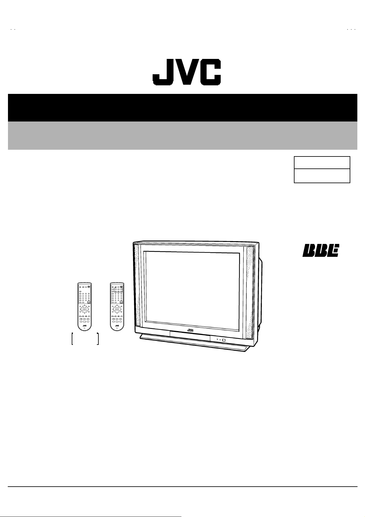
COLOR TELEVISION
AV-32F703
AV-32F713
AV-32F803
BASIC CHASSIS
RM-C 326G
RM-C326
AV -3 2F70 3
AV -3 2F71 3
[RM-C 325G]
AV -3 2F80 3
AV-32F703
AV-32F713
AV-32F803
/Y
/Y
/Y
GJ
CONTENTS
! SPECIFICATIONS ・・・・・・・・・・・・・・・・・・・・・・・・・・・・・・・・
!
SAFETY PRECAUT IONS
!
FEATURES・・・・・・・・・・・・・・・・・・・・・・・・・・・・・・・・
! HOW TO IDENTIFY MODELS ・・・・・・・・・・・・・・・・・・・・・・・・・・・・・・・・
!
MAIN DIFFERENCE LIST
! FUNCTIONS ・・・・・・・・・・・・・・・・・・・・・・・・・・・・・・・・
! SPECIFIC SERVICE INSTRUCTIONS ・・・・・・・・・・・・・・・・・・・・・・・・・・・・・・・・
!
SERVICE ADJUSTMENTS ・・・・・・・・・・・・・・・・・・・・・・・・・・・・・・・・
! PARTS LIST ・・・・・・・・・・・・・・・・・・・・・・・・・・・・・・・・
★ OPERAT ING INSTRUCTIONS
★ STAND ARD CIRCUIT DIAGRAM ・・・・・・・・・・・・・・・・・・・・・・・・・・・・・・・・
1
・・・・・・・・・・・・・・・・・・・・・・・・・・・・・・・・・・・・・・・・・・・・・・・・・・・・・・・・・・・・・・・・
・・・・・・・・・・・・・・・・・・・・・・・・・・・・・・・・・・・・・・・・・・・・・・・・・・・・・・・・・・・・・・・・
・・・・・・・・・・・・・・・・・・・・・・・・・・・・・・・・・・・・・・・・・・・・・・・・・・・・・・・・・・・・・・・・
・・・・・・・・・・・・・・・・・・・・・・・・・・・・・・・・・・・・・・・・・・・・・・・・・・・・・・・・・・・・・・・・
・・・・・・・・・・・・・・・・・・・・・・・・・・・・・・・・
・・・・・・・・・・・・・・・・・・・・・・・・・・・・・・・・・・・・・・・・・・・・・・・・・・・・・・・・・・・・・・・・
・・・・・・・・・・・・・・・・・・・・・・・・・・・・・・・・・・・・・・・・・・・・・・・・・・・・・・・・・・・・・・・・
・・・・・・・・・・・・・・・・・・・・・・・・・・・・・・・・・・・・・・・・・・・・
・・・・・・・・・・・・・・・・・・・・・・・・・・・・・・・・・・・・・・・・・・・・・・・・・・・・・・・・・・・・・・・・
・・・・・・・・・・・・・・・・・・・・・・・・・・・・・・・・・・・・・・・・・・・・・・・・・・・・・・・・・・・・・
・・・・・・・・・・・・・・・・・・・・・・・・・・・・・・・・・・・・・・・・・・・・・・・・・・・・・・・・・・・・・・・・
・・・・・・・・・・・・・・・・・・・・・・・・・・・・・・・・
・・・・・・・・・・・・・・・・・・・・・・・・・・・・・・・・・・・・・・・・・・・・・・・・・・・・・・・・・・・・・・・・
・・・・・・・・・・・・・・・・・・・・・・・・・・・・・・・・・・・・・・・・・・・・・・・・・・・・・・・・・・・・・・・・
・・・・・・・・・・・・・・・・・・・・・・・・・・・・・・・・・・・・・・・・・・・・・・・・・・・・・・・・・・・・・・・・
・・・・・・・・・・・・・・・・・・・・・・・・・・・・・・・・・・・・・・・・・・・・・・・・・・・・・・・・・・・・・・・・
・・・・・・・・・・・・・・・・・・・・・・・・・・・・・・・・・・・・・・・・・・・・・・・・・・・・・・
・・・・・・・・・・・・・・・・・・・・・・・・・・・・・・・・・・・・・・・・・・・・・・・・・・・・・・・・・・・・・・・・
・・・・・・・・・・・・・・・・・・・・・・・・・・・・・・・・・・・・・・・・・・・・・・・・・・・・・・・・・・・・・・
・・・・・・・・・・・・・・・・・・・・・・・・・・・・・・・・・・・・・・・・・・・・・・・・・・・・・・・・・・・・・・・・
・・・・・・・・・・・・・・・・・・・・・・・・・・・・・・・・・・・・・・・・・・・・・・・・・・・・・・・・・・・・・・・・
・・・・・・・・・・・・・・・・・・・・・・・・・・・・・・・・・・・・・・・・・・・・・・・・・・・・・・・・・・・・・・・・
・・・・・・・・・・・・・・・・・・・・・・・・・・・・・・・・・・・・・・・・・・・・・・・・・・・・・・・・・
・・・・・・・・・・・・・・・・・・・・・・・・・・・・・・・・・・・・・・・・・・・・・・・・・・・・・・・・・・・・・・・・
COPYRIGHT © 2002 VICTOR COMPANY OF JAPAN, LTD.
・・・・・・・・・・・・・・・・・・・・・・・・・・・・・・・・・・・・・・
・・・・・・・・・・・・・・・・・・・・・・・・・・・・・・・・・・・・・・・・・・・・・・・・・・・・・・・・・・・・・・・・
・・・・・・・・・・・・・・・・・・・・・・・・・・・・・・・・
・・・・・・・・・・・・・・・・・・・・・・・・・・・・・・・・・・・・・・・・・・・・・・・・・・・・・・・・・・・・・・・・
・・・・・・・・・・・・・・・・・・・・・・・・・・・・・ 4
・・・・・・・・・・・・・・・・・・・・・・・・・・・・・・・・・・・・・・・・・・・・・・・・・・・・・・・・・・
・・・・・・・・・・・・・・・・・・・・・・・・・・・・・・・・
・・・・・・・・・・・・・・・・・・・・・・・・・・・・・・・・・・・・・・・・・・・・・・・・・・・・・・・・・・・・・・・・
・・・・・・・・・・・・・・・・・・・・・・・・・・・・・・・・・・・・・・・・・・・
・・・・・・・・・・・・・・・・・・・・・・・・・・・・・・・・・・・・・・・・・・・・・・・・・・・・・・・・・・・・・・・・
・・・・・・・・・・・・・・・・・・・・・・・・・・・・・・ 12
・・・・・・・・・・・・・・・・・・・・・・・・・・・・・・・・・・・・・・・・・・・・・・・・・・・・・・・・・・・・
・・・・・・・・・・・・・・・・・・・・・・・・・・・・・・・・・・・・・・・・・・
・・・・・・・・・・・・・・・・・・・・・・・・・・・・・・・・・・・・・・・・・・・・・・・・・・・・・・・・・・・・・・・・
・・・・・・・・・・・・・・・・・・・・・・・・・ 2- 1
・・・・・・・・・・・・・・・・・・・・・・・・・・・・・・・・・・・・・・・・・・・・・・・・・・
・・・・・・ 2
・・・・・・・・・・・・
・・・・・・・・・・・・ 4
・・・・・・・・・・・・・・・・・・・・・・・・
・・・・・・・・・・・ 6
・・・・・・・・・・・・・・・・・・・・・・
・・・・・・・・・・・・・・・・・・・・・・ 8
・・・・・・・・・・・・・・・・・・・・・・・・・・・・・・・・・・・・・・・・・・・・
・・・・・・・・・・ 33
・・・・・・・・・・・・・・・・・・・・
No.520 04
Jun. 2002
Jun. 2002
3
5
Page 2
A
V-32F703
A
A
V-32F713
V-32F803
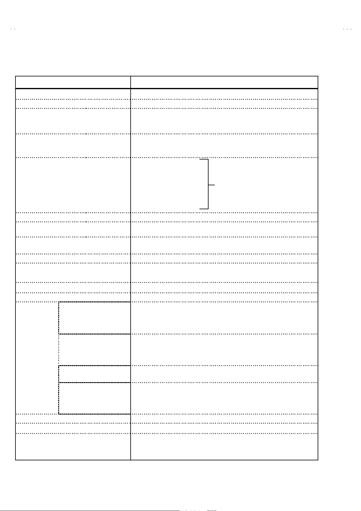
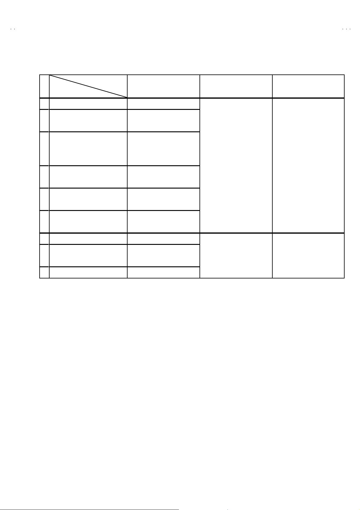
SPECIFICATIONS
Items Cont e nts
Dimensions (W
Mass 14 0.8 Ibs ( 6 4.0 kg)
TV System
and C olor S yste m
TV Receiving Channels
and Frequency
CATV Receiving Channels
and Frequency
Intermediate Fr equency Vide o IF Car rier
Color Sub Carrier 3.58MHz
Power Input 12 0V AC , 60H z
Power Consumption 16 0W
Pictur e Tube 32 ” (8 0cm ) M ea sured Diag on al l y
Hi gh Vo l t ag e
Speake r
Audio Power Out put 5W + 5W
Input terminals
Fix Audio Output 50 0m V( r ms) ( - 4d Bs ) LO W Imped ance (40 0Hz w he n mod ul a ted 10 0%)
AV compulink ⅢⅢⅢⅢ Input 3.5 m m mi ni jac k
Antenna terminal 75Ω(VHF/UHF) Terminal, F-Type Connector
Remote Control Unit RM-C 32 6G(AV-32F703) / R M- C32 6( AV- 32 F71 3) /R M-C32 5G (AV -32F8 03 )
××××H××××
D) 34 - 5/8 ”×27”-5/8”×22-1/4” (877mm×69 9m m×5 65m m)
TV RF Syste m
Color System
Sound System
VL B a nd
VH B and
UHF Band
Low Band
High Band
Mid Band
Super Band
Hy p er Band
Ul tr a B an d
Sub Mid Band
TV/CATV Total Channel 18 0 Cha nn el s
Sound IF Carrier
Input 1 (Rear) S-Video
Vide o
Audio (L/MON O, R)
Input 2 (Rear) Video
Component video
Audio (L/MON O, R)
Input 3 (Front) Video
Audio (L/MON O, R)
Input 4 (Rear)
(For AV-32F8 03)
Component video
Audio (L/MON O, R)
CCIR(M)
NTSC
BTS C S ys tem ( M ul ti -Ch an nel S ound )
(02~06) 54 MHz ~88MHz
(07~13) 17 4M H z~21 6M Hz
(14~69) 47 0M H z~80 6M Hz
(02~06, A-8) by (02~06&0 1)
(07~13) by (07~13)
(A~1) b y (14~22)
(J~W) by (23~36)
(W +1~W+28) b y (37~64)
(W +29 ~W +84) b y ( 65 ~1 25)
(A8, A4~A1) by (01, 96~99 )
45 .75 MHz
41.25 MHz ( 4 .5MH z)
31 .4 kV±1.3kV (at zero beam current)
2”×4 -3/ 4” ( 5×12 cm ) Oval t ype×2
Y : 1V(p -p ) P ositive ( N eg ativ e s ync p rovided, w h en term i nat ed with 75 Ω)
C : 0 .28 6V(
1V (p- p ), 75 Ω
50 0m V( r ms) ( - 4d Bs ), High Im pe dance
1V p- p, 75 Ω
Y : 1 V( p- p) P ositive ( N eg ati ve sync provide d, when ter m i na ted with 7 5Ω)
PB, PR : 0.7V(p-p), 75Ω
50 0m V( r ms) ( - 4d Bs ), High Im pe dance
1V (p -p ), 75 Ω
50 0m V( r ms) ( - 4dB s ), High Im pe dance
Y : 1 V( p- p) P ositive ( N eg ati ve sync provide d, when ter m i na ted with 7 5Ω)
PB, PR : 0.7V(p-p), 75Ω
50 0m V( r ms) ( - 4d Bs ), High Im pe dance
(AA/R 6 /UM- 3 bat ter y×2)
p-p
) (Burst si g nal , wh en te rmina ted with 7 5 Ω)
(54MHz~ 80 4MH z)
De sign & speci f icat ions ar e su bject to chang e wi th ou t notice.
2
No.52004
Page 3
A
3
A
3
A
3
SAFETY PRECAUTIONS
V-32F70
V-32F71
V-32F80
1. The d esi gn of t hi s p ro du ct c ont ai ns spec i al h ar dw ar e, man y
ci rcu its and co mp on ent s s pecial l y for saf ety purp oses. For
continued protection, no changes should be made to the
origi na l des ig n unl ess a uthor ized in wr iti ng by t he m an ufac tu re r.
Replacem en t parts must be ident ic al t o thos e us ed in th e
origi na l c ircui t s . S ervic e sho ul d be perf or me d b y qu al i fi ed
p ers onnel o nl y.
2. Alte r ati on s of th e des i g n o r circu i tr y of the p rodu cts s hou ld n ot
b e m ad e. A ny desi gn al te rations or ad di tio ns will vo id th e
manufacturer's warranty and will further relieve the
manu fact ur er of resp ons ib ilit y for pers ona l in ju r y or p rope rt y
d am age r esu lt in g t heref rom .
3. M an y electr i cal an d m ech an ic al pa rt s in th e produ cts h ave
sp ecial saf ety- r el at ed charact eris tic s. These charac teri stics ar e
oft en n ot e vid en t fr om v isu al in spe ction no r can t he prote ction
aff or de d by them n ecess ar ily be obtained b y usi ng
replac ement c o mp on ents ra ted for h ig her vo ltag e, wa ttag e, etc.
Replacem en t pa rt s whic h h av e t hes e sp ecial s afet y
ch aracteristi c s a re i d entified in th e par ts l ist of S ervic e m an ual.
Electrical components having such features a re identified
by shading on the schematics and by (!!!!) on the parts list
in S erv ice manual . The u se of a subst itute re plac emen t whi ch
does not have the same saf ety characteristics as the
reco mm en de d replac em en t pa rt s ho wn in the pa rts l ist of
Se rvi ce ma nu al m ay c ause sh ock, f ire, or o ther hazards.
4. Use iso la tio n tr an sf orme r when hot chassis .
The chassis and any sub-chassis contained in s ome products
are c on nect ed to one si de of th e AC p ower l i ne . An i sol a tion
tr ansf or m er of ad equ ate c ap ac ity sh ou ld be ins er t ed bet we en
th e p r odu ct and t he AC p ow er su pp ly p oint while p erfor ming
an y s er vic e on so me pr o duc ts when th e HOT c h assis is
exp ose d.
5. Don't shor t between the LIVE side ground and I SOLATED
(NE UTRAL) side ground or EARTH side ground when
repairing.
So m e m od el 's p ower c irc uit is par t ly di f feren t in t he GND. Th e
diff er enc e of t he GND is sh ow n by th e LI VE : (") side GND,
th e ISO LATED( N EUTRA L) : (#) s ide GN D an d EAR TH : ( $)
si de GND . Don 't sho rt be tween t he LIVE s id e GN D a nd
ISO LATE D(N EUTRAL) side GND or EARTH si de GND and
never measure with a measuring apparatus (oscilloscope etc.)
th e LI VE side GND a nd ISO LATED(N EU TRA L) si d e G ND or
EARTH side GND at the s ame time.
If above note will not be kept, a fuse or any parts will be broken.
6. If any repa ir h as b een m ade to th e chass is, it is re c ommend ed
th at t he B1 se ttin g sh ou ld b e chec ked or adjuste d (S ee
ADJUST M ENT OF B 1 POW E R SUPPL Y).
7. The hig h volt ag e app lied t o the pictu re tube mu st co nform wi th
that specified in Service manual. Excessive high voltage can
cau s e an incr ea se i n X-Ra y emi ssi on , a rci n g and p ossi bl e
com po ne nt d am ag e, th er ef ore op er ati o n un der excess i ve hi gh
vol ta ge c ond it i ons sh ou ld be k e pt to a m in imum, or sh ould be
preve nt ed. I f s evere arc in g occu rs, r em ov e th e AC p ower
immediately and determine the cause by visual inspection
(inc or r ect installa tion , crac ked o r melte d hi gh voltag e h ar nes s,
p oor s olde rin g, etc. ). T o mainta in the pr op er minim um le vel of
soft X-Ra y emission, components in the high voltage circuitry
incl ud i ng the picture tu be mus t be the ex a ct r ep l acemen ts or
alte rn at ives appr o ved b y th e manuf actu r er of th e co mp l ete
prod uct.
8. Do n ot c hec k hi gh vol ta ge by d r aw in g a n ar c . U s e a hi gh
vol ta ge m ete r or a hi gh volt age pro be wi th a VT VM . Di sc h ar ge
th e p ictu r e tu be bef or e a tte mp ting meter co nne cti on , b y
con nec ting a c lip lead t o th e gr ou nd fr am e a nd con n ecti ng t he
oth er e nd of t he lead th roug h a 10kΩ 2W resist or to t he anode
bu tto n.
9. W hen s e rvi c e i s required, ob s er ve th e o rig in al l ea d dr es s.
Extra p r ecau tion sh ould be given t o assu re cor re ct lea d dr es s
in the h i gh v olta ge c ircu it ar ea . W her e a sh ort cir c ui t ha s
occu rre d, th ose c omp on en ts th at i nd ic ate ev iden ce of
overheating should be replaced. Always use the
manu fact ur er 's replace m ent compon ents .
10 . Isolation Check
(Safety for Electrical Shock Hazard)
Af ter re-a ssem bl ing th e pr od uct , always pe rf or m an iso lation
ch ec k on th e expo s ed m etal p ar ts of the c abin et ( ant en na
ter m ina ls, vi de o/a ud i o in pu t and out put t er mi n al s, Con tr ol
knobs, metal cabinet, screwheads, earphone jack, control
sh afts, etc .) to be sure th e pr o duct is saf e t o op er at e w i th out
d ang er of elect rica l shoc k.
(1) Di electric Strength Test
The is olat ion b etwe en the AC pri ma r y cir cu it and al l m eta l parts
exp osed t o th e us er, par ticu larly an y expo sed m etal p art h aving
a re tur n pat h to the ch assi s sh ou ld w i ths t and a volta ge of
11 00V AC ( r .m.s.) f or a p eriod of one s ec ond.
(. . . . Withstand a voltage of 11 00V AC (r.m. s.) to an applian ce
rate d up to 120V , a nd 3 000V AC ( r .m. s.) t o an appl i anc e ra ted
200V or more, for a period of one second.)
Thi s meth od of tes t re qu ires a t est eq uip me nt n ot g en er al l y
fou nd in t he servi ce t ra de.
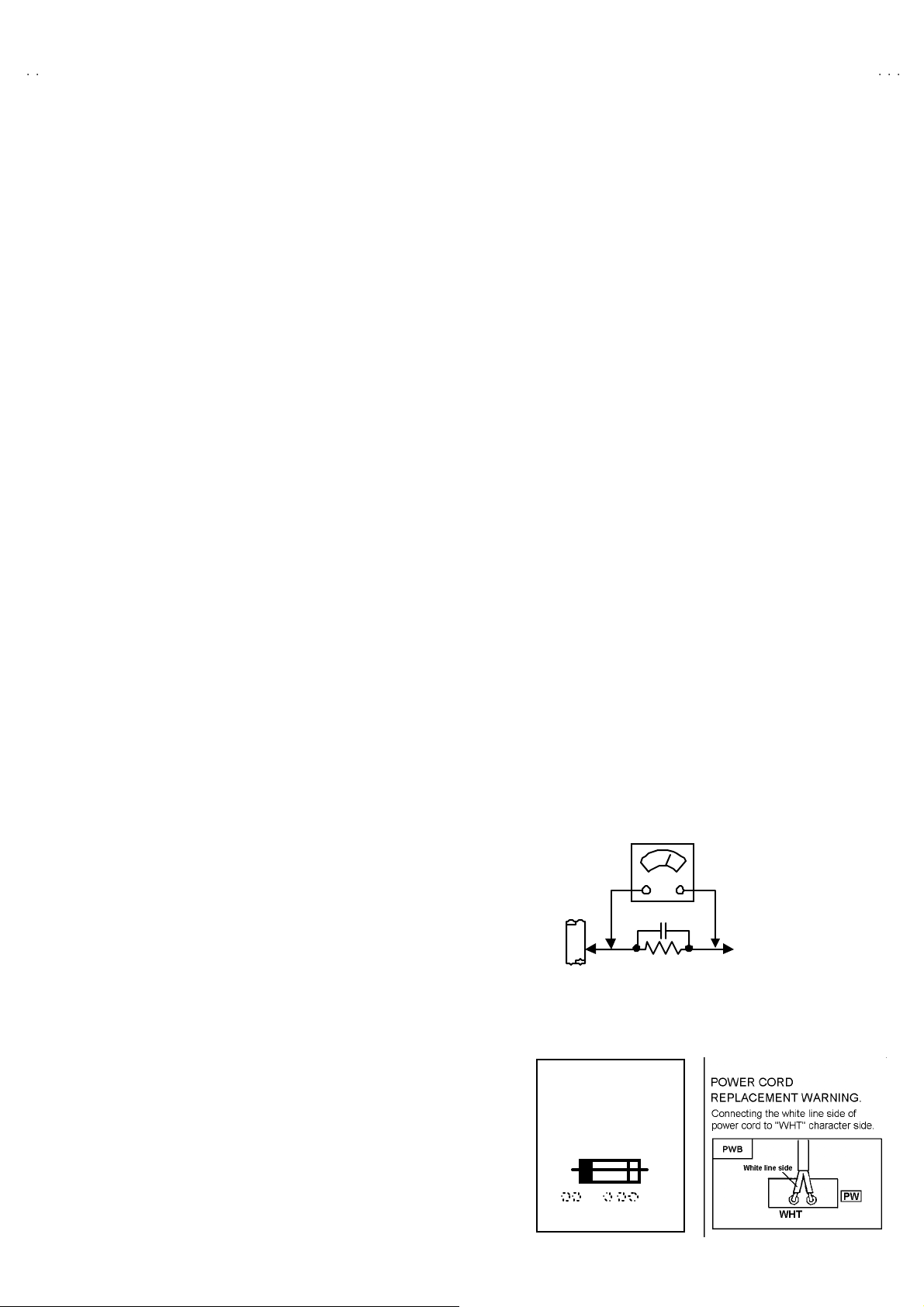
(2) Leakage Current Check
Plug t he A C line c ord direct ly int o th e AC ou tl et ( do not u s e a
line is olation tra nsf orm er dur i ng t his che ck.) . Using a " L eakage
Curr ent Tes t er", mea sure t he lea kag e cur r en t fr om each
exp os e d m etal part of th e ca bine t, partic ul ar l y an y expo s ed
metal part having a retur n path to the ch assis, to a known good
ea rt h gr o und (water p ipe, etc.). A ny lea kag e cur r en t must not
exce ed 0. 5mA AC ( r.m. s.).
Howev e r, i n t ropical a r ea, thi s m us t not e xc eed 0 .2m A AC
(r.m.s.).
"""" Altern at e Che ck M ethod
Plug t he A C line c ord direct ly int o th e AC ou tl et ( do not u s e a
line isolation transformer during this check.). Use an AC
vol tm et er h aving 100 0 o hm s per vol t or more sen s iti vit y in the
follo win g manner. C on nec t a 150 0Ω 1 0W r esistor pa ralle l ed
by a 0.15μ F AC-typ e cap ac i tor b etween an exp ose d meta l
p art and a kno wn g o od ear th gr ou nd (wate r pipe, et c.).
Measu r e th e A C voltag e ac r oss th e resi st or w it h t he AC
voltmeter. Move the res istor connection to each exposed metal
part, particularly any exposed metal part having a return path to
th e ch assis , an d m ea s ur e t he A C vol ta ge acr os s th e r esis to r.
Now, reve rs e th e pl u g in t he A C out let a nd r ep e at e ach
measu r em en t. An y volta ge me as u re d m ust not exce ed 0.7 5V
AC (r.m. s.) . This corresp on ds t o 0 .5mA AC (r.m. s.) .
Howev e r, in tropic al ar ea, this m ust n ot exc ee d 0 .3V AC
(r.m.s.). T his corr esponds to 0.2m A AC ( r.m.s.).
AC VOLT METER
(HAVING 1000 Ω/V,
GOOD
EARTH
GR OUND
11 . High voltage hold down circuit check.
Af ter rep air of the hi gh volt ag e h old down ci r cuit, th is circu i t
sh all be c hecked to op er ate corr ectly.
See ite m "Ho w to check the high voltage hold down
cir cuit".
This mark shows a fast
operating fuse, the
letters indicated below
show the r ati ng.
0.15μF AC-T YPE
1500Ω 10W
OR MOR E SENSIT IVITY)
PLACE THIS PROBE
ON E A C H EX PO SE D
ME T AL PA RT
A V
No. 52004
3
Page 4
A
V-32F703
A
A
V-32F713
V-32F803
FEATURES
• New c hassis de s ign en abl es us e of a si ngl e b oard w ith simplifi ed
circuit ry.
• Users c an make fun to c onn ect the DVD p layer wit h th e component
vid eo signal i npu t termi na l.
• Provid ed with mini atu re tuner ( TV/ CATV).
•
Multif unct ional rem ote con tro l p erm its pic tu re a djustment.
• Adopti on of the CHANN EL GUARD fun ction prevents t he sp eci fi c
chan nels from being selected, unl ess th e “ID nu mbe r” is key in .
2
• I
C bus control utilizes single chip ICs.
•
Adoption of the VIDEO STATUS / THEA TER PRO. functi on.
•
Ad opti on of the ON /OF F TIM ER and SLE EP TI MER fu nction.
• Bu ilt-in V-CHIP system.
•
Clos ed- caption b roadcas ts can be view ed.
•
Built-in MTS system, BB E / HYPER- SURROUND system.
• S-VIDEO in put termi nal for tak i ng best advantag e of S uper VH S.
•
Digit al Comb fi lter Imp roved picture quality .
• Bu ilt-in EZ SURF system.(AV-32F803)
By pus h in g the EZ SU R F key , the coun terprogram info rmation can
be displ ayed in t he te xt form that is obtain ed f rom t he three program
informatio n: t he CALL LE T TER (broadcast in g s tation ID), netw or k
names an d progr am nam es i n the XDS d ata. W hen the P IP f un ctio n
is tur ned on, the coun terpr ogr ams will be d isp layed on the PI P one by
one whil e th e text on t he main scr een i s displ ayed si m ult aneou s ly.
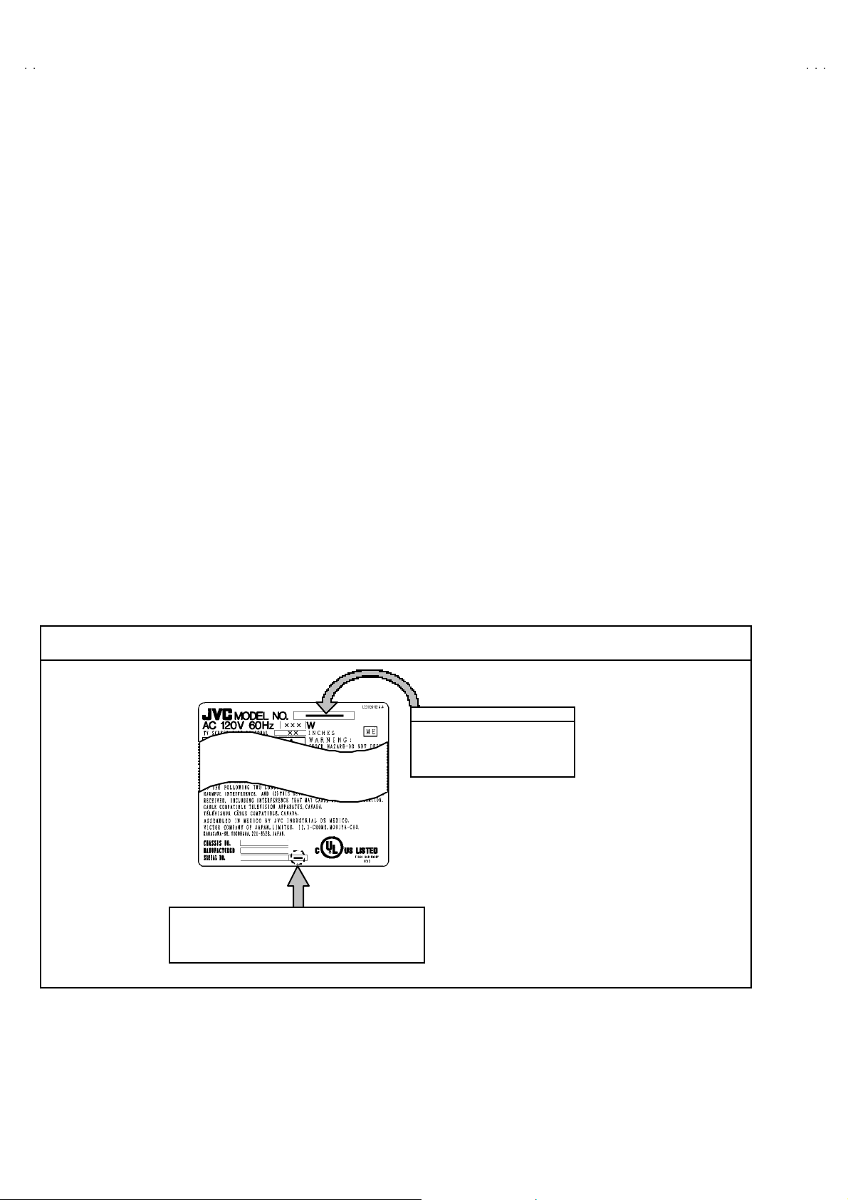
HOW TO IDENTIFY MODELS
How t o re cognize f ro m the ap pea ran ce of th e model concerne d is wri tten be low. Plea se di st in guish from sev eral co ntents cu rr ently
printe d on the rating label.
[RATING LABEL]
Indicated Basic Model Name
AV -32 F703
AV -32 F713
AV -32 F803
Indic ated “Y ” letter as model att ribu te nam e.
4
No.52004
Page 5
A
A
A
MAIN DIFFERENCE LIST
V-32F703
V-32F713
V-32F803
!!!!
Parts Name
MAIN PW B SGJ -1010A -M2 SGJ -1012A -M2 SGJ -1011A -M2
PIP PWB SGJ -4 001A-M 2 ××
AV SE L PWB SGJ -5001A -M2 SGJ -5002A -M2
3D Y/C S EP M OD ULE PWB SGJ 0Y00 1A- M2 ××
!
FR ON T CABI. ASSY LC11048 -0 03B- A (Si l ver)
JVC M AR K CM48006 -008- C
! DOOR LC20 628-0 01C- A
!
KNOB (P OWER) LC31237 -0 01A- A
OPERATION SHEE T LC31238-004A-A
!
CONTR OL K NOB LC20217 -0 04B- A
!
TERM INA L BOARD LC20899 -0 05A- A LC20 899 -0 04A- A
REMO CO N UNIT RM-C 325 G-1A RM-C 326 G-1A RM-C 326 -1 A
Comb filter 3D Y/C separate comb filter 3 line digital comb filter
Pictur e in Pic tur e 2 Tun er PIP NO
Model name
AV-32F803
/Y
AV-32F703
/Y
AV-32F713
/Y
←
←
←
←
←
←
←
LC11048 -0 04A- A (Bl ack)
CM48006 -009-C
LC20628 -0 02A- A
LC31237 -0 02A- A
LC31238 -0 05A- A
LC20217 -0 06A- A
←
←
←
EZ Su rf YES NO
I nput Terminal Input1 ~Input4 Inp ut1~Input3
←
←
No.52004
5
Page 6
A
V-32F703
A
A
V-32F713
V-32F803
FUNCTIONS
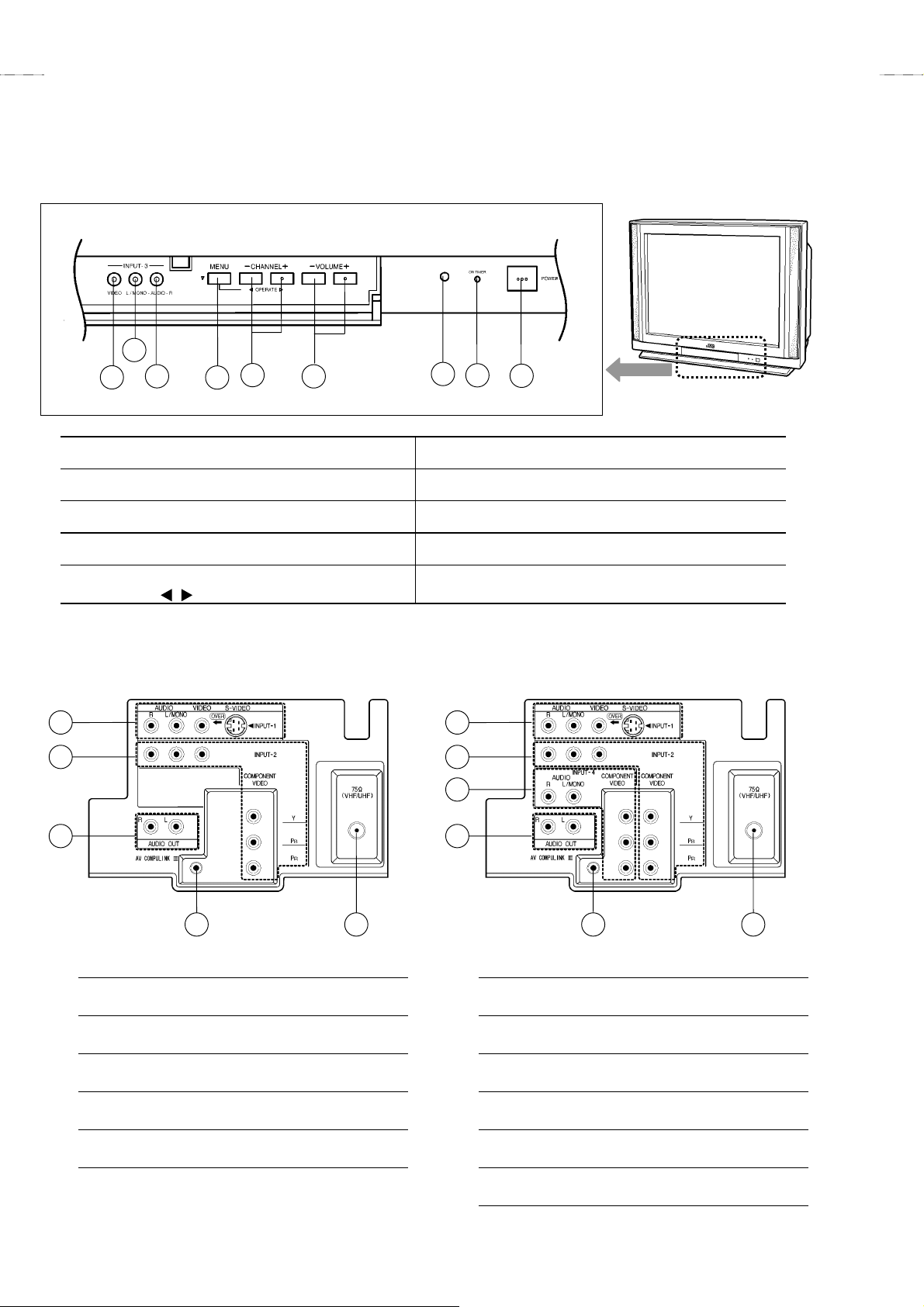
FRONT PANEL CONTROL
2
3
1
INPUT3 VIDEO terminal
1
4
5
6
7
8
9
VOLUME -/+ buttons
6
INPUT3 AUDIO L/MONO terminal
2
INPUT3 AUDIO R terminal
3
MENU button (▼)
4
CHANNEL -/+ buttons
5
OPERATE / buttons (use MENU screen)
REAR TERMINAL
[[[[ AV-32F703
1
2
3
4 5
, AV-32F713/Y ] [[[[ AV-32F803
/Y
SENSOR, REMOTE CONTROL
7
ON TIMER LED
8
POWER button
9
1
2
3
4
]
/Y
5 6
[[[[ AV-32F703/Y, AV-32F713/Y ]
1INPUT 1 (S-VIDEO, V, L/MONO, R) terminals
INPUT 2 (V, L/MONO, R) terminals
2
/ COMPONENT VIDEO(Y, P
AUDIO OUT(L, R) terminals
3
AV COMPULINK Ⅲ
4
VHF / UHF terminal
5
6
, PR) terminals
B
No.52004
[[[[ AV-32F803/Y ]
1INPUT 1 (S-VIDEO, V, L/MONO, R) terminals
INPUT 2 (V, L / MONO, R) terminals
2
/ COMPONENT VIDEO(Y, P
INPUT 4 (L, R) terminals
3
/ COMPONENT VIDEO(Y, P
AUDIO OUT(L, R) terminals
4
AV COMPULINK Ⅲ
5
VHF / UHF terminal
6
, PR) terminals
B
, PR) terminals
B
Page 7
AV-32F703
AV-32F713
AV-32F803
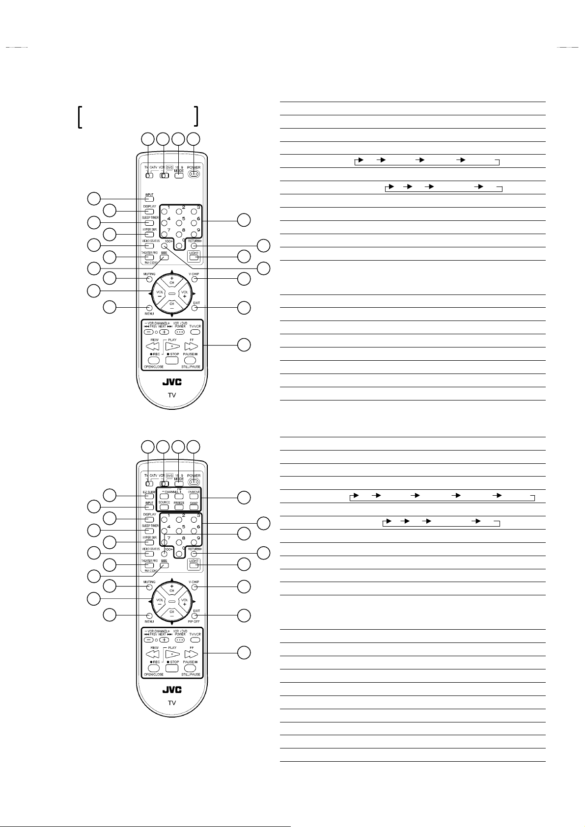
REMOTE CONTROL UNIT
RM-C326G : AV-32F703/Y
RM-C326 : AV-32F713/Y
1 2 3 4
5
6
7
8
9
10
11
12
13
14
15
18
19
20
21
1TV / CATV switch
2VCR / DVD switch
316 : 9 MODE Key
4POWER Key
5INPUT
6DISPLAY key
7SLEEP TIMER Key
8HYPER SUR. Key
9VIDEO STATUS Key
ATHEATER PRO key
BBBE key
17
CMUTING Key
16
DFUNCTION Key ( CH -/+ / VOL -/+ )
EMENU Key
FNUMBERS Key
G100+ Key
HRETURN+ Key
ILIGHT Key
JV-CHIP Key
KEXIT Key
LVCR / DVD Keys
Key
The FUNCTION keys operate the CHANNEL and VOLUME normally.
These keys also operate the MENU system.
TV VIDEO1 VIDEO2 VIDEO3
(
(
0 15 30 ……165 180
)
)
[RM-C325G : AV-32F803/Y]
1 2 3 4
23
5
6
7
8
9
10
11
12
13
14
22
16
18
19
20
21
1TV / CATV switch
2VCR / DVD switch
316 : 9 MODE Key
4POWER Key
Key
5INPUT
6DISPLAY key
15
7SLEEP TIMER Key
8HYPER SUR. Key
9VIDEO STATUS Key
17
ATHEATER PRO key
BBBE key
CMUTING Key
DFUNCTION Key ( CH -/+ / VOL -/+ )
EMENU Key
FNUMBERS Key
G100+ Key
HRETURN+ Key
ILIGHT Key
JV-CHIP Key
KEXIT / PIP OFF Key
LVCR / DVD Keys
MPIP Key
NEZ SURF Key (Back Program Information can be displayed.)
The FUNCTION keys operate the CHANNEL and VOLUME normally.
These keys also operate the MENU system.
TV VIDEO1 VIDEO2 VIDEO3 VIDEO4
(
0 15 30 ……165 180
(
)
)
No.52004
7
Page 8

A
V-32F703
A
A
V-32F713
V-32F803
SPECIFIC SERVICE INSTRUCTIONS
DISASSEMBLY PROCEDURE
REMOVING THE REAR COVER
1. D isc onnect t he po w er plu g f ro m A C ou tlet.
2. As s hown i n th e Fig .1, rem o ve th e 12 screws marked
3. W i thdr a w t he r ear c over b ackw ar d.
!!!!
.
CHECKIN G THE CHASSIS
To check the PW Board fro m back side.
1. Pu ll out the ch assis (re fer t o REM OVI NG THE CHA SSIS) .
2. Erect th e c has sis ver ti ca lly so th at y ou can ea sil y check th e bac k
si de of the PW Boar d.
REMOVING THE TERMINAL BOARD
" After removing the rear cover.
1. As s hown i n Fig.1 , r emo ve t he scre ws ma rked
2. Withdraw the terminal board toward you.
""""
.
REMOVING THE CHASSIS
" After removing the rear cover and terminal board.
1. Sl i ght ly r ai se t he both si d es of c h assi s b y hand an d r em o ve th e
claws u nder th e both sid e of th e ch assis from th e front cabi net.
2
2. W i thdr a w t he c hass is backw a rd .
(If n ecess ary , r em ove t he wire clamp, c onnec t ors etc.)
REMOVING THE SPEAKER
" After removing the rear cover.
1. A s shown i n Fig. 1 , re mo v i ng th e 2 scr ews m ar k ed
remove the sp eaker with the speaker holder
2. Then r e mo ve the 2 s cr ews m ar ked
fr om sp eake r ho ld er .
3. Follow th e s ame st eps wh en r em oving th e oth er ha nd sp eak er.
NOTE : When removing the 2 screws mark ed
remove t he lower si de s cr ew f irs t, and th en remove th e
up per one .
to detac h th e s peaker
$%
$%
$%$%
####
####,
of th e s p eak e r ,
then
[CAUT ION]
"
When e r ec ti ng th e ch assis, be car ef ul so tha t there will b e no
contacting with other PW Board.
"
Be for e tu rn ing o n p ower , make s ur e th at t he w i r e connec tor is
prop er ly c on nec ted .
"
When conducting a check with power supplied, be sure to
confirm that the CRT EARTH WIRE (BRAIDED ASS’Y) is
connected to the CRT SOCKET PW board.
WIRE CLAMPIN G AND CABLE TYING
1. Be sure t o clamp th e wire.
2. Never remove the c able tie use d f or tying th e wi res togethe r.
Should it b e inadverte ntly removed, be sure to tie the wir es with a
new cable tie.
REMOVING THE LED & POWER SW PWB
" After removing the rear cover and terminal board.
1. R em ove t h e 2 screws ma rked
2. Withdra w t he LE D & P OW ER SW PW B t oward yo u .
* If nec essary, remo ve th e wire clamp, connecto r etc.
as s hown in Fig. 1.
&&&&
REMOVING THE FRONT CONTROL PWB
"
After removing the rear cover & terminal board.
1. R em ove t h e 2 screws ma rked
2. Withdraw the FRONT CONTROL PWB toward you.
* If nec essary, remo ve th e wire clamp, connecto r etc.
8
as s hown in Fig. 1.
''''
No.52004
Page 9
A
3
A
3
A
3
-
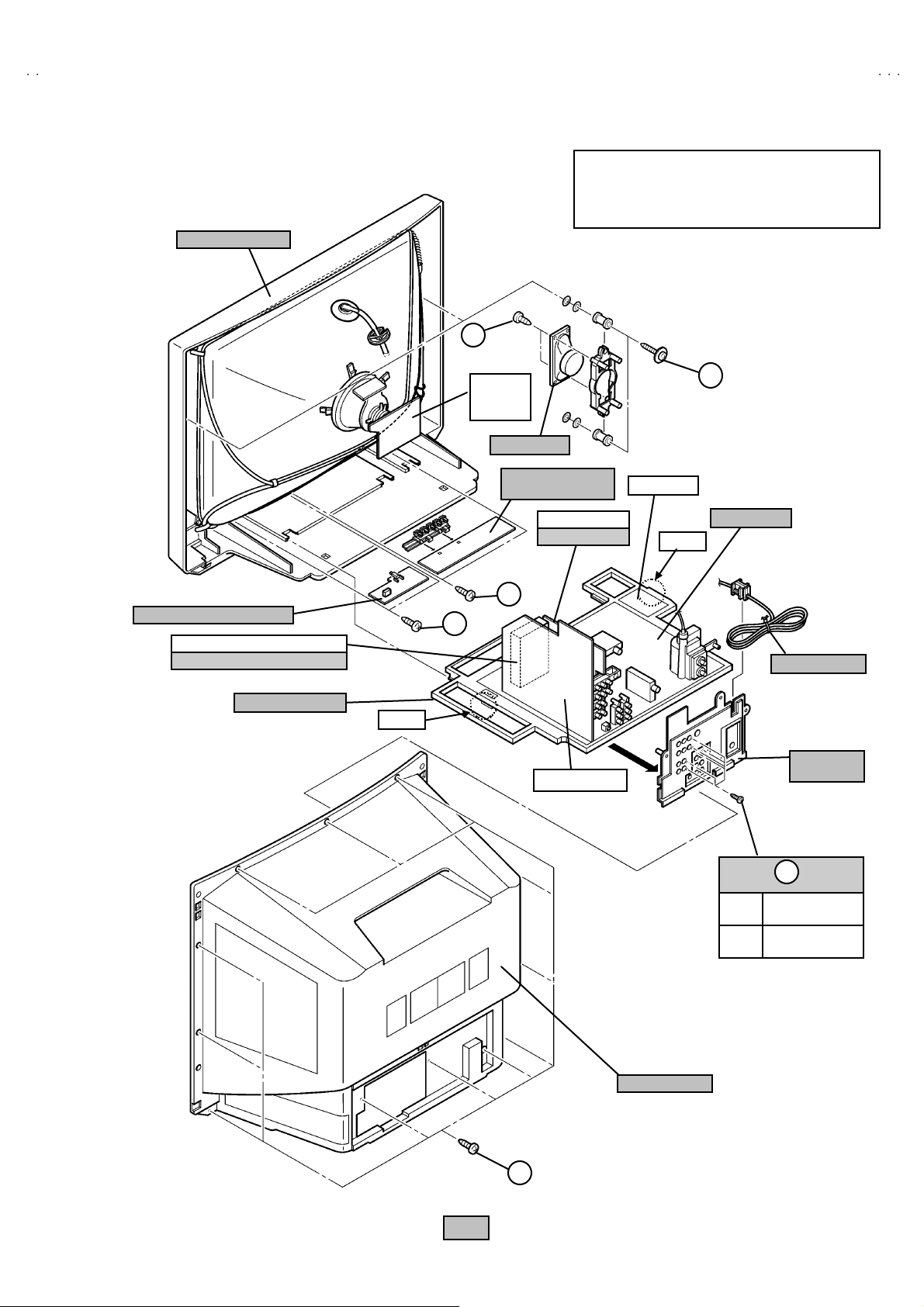
FRONT CABINET
V-32F70
V-32F71
V-32F80
This illustration describes about the AV-32F803/Y.
When di sas semblin g t he AV -32F 7 03/Y an d AV
32 F71 3/Y, you ca n us e th is illus tr atio n as same ste ps
as AV-32 F80 3/Y.
D
LED & POWER SW PWB
3D Y/C SE P MODULE PW B
AV-32F803
CHASSIS BASE
CRT
SOCKET
PWB
SP EAKER
FRONT CONTROL
PWB
PIP PW B
AV-32F803
DAF PWB
/Y
C
MAIN PWB
CLAW
F
E
/Y
CLAW
AV SE L PWB
POWER CORD
TERMINAL
BOARD
B
(××××6) AV-32F803
(×××× 4) AV-32F703
AV-32F713
REAR COVER
/Y
/Y
/Y
A
Fig .1
No.52004
9
Page 10
A
V-32F703
A
A
)
/C( S )
)
/
A
▼/
S
US
/
V-32F713
V-32F803
MEMORY IC REPLACEMENT
1. Memory IC
This TV uses memory IC.
Thi s memory IC s t ores dat a for prop er o pera ti on of the vide o and deflecti o n cir cuits.
When r ep la cing t he m em or y IC , be sure to use an IC c o nta ini ng th is (initia l value ) d ata.
2. Memory IC replacement procedure
(1) Power off
Switch off the p ower and discon nec t t he p ower plug fr om th e AC
ou tl et.
(2) Replace the memory IC
Be sure t o use a memory I C wri tte n with the initi al settin g data.
(3) Power on
Con nect the power plug to the AC o utle t and switc h o n the power.
SE RV I CE MENU
SERVICE MENU
1.V
3.S OUND(A) 4.OT HERS(F)
5.PIP(PIP) 6.3L Y/C(LYC)
7. LO W LIG HT 8. HI GH LI GH T
9.RF AF C 10.V CO
2
C BUS 12.SYSTEM(SYS)
11.I
2.DE F(D
AV-32F803
6.3D Y/C(DYC)
Y
(4) Co nfir m the syst em const ant value
"
Norma l l y, do not a djust the 12.S YSTEM ( SYS ).
"
W hen ad just, be sure t o i n put the si gn al.
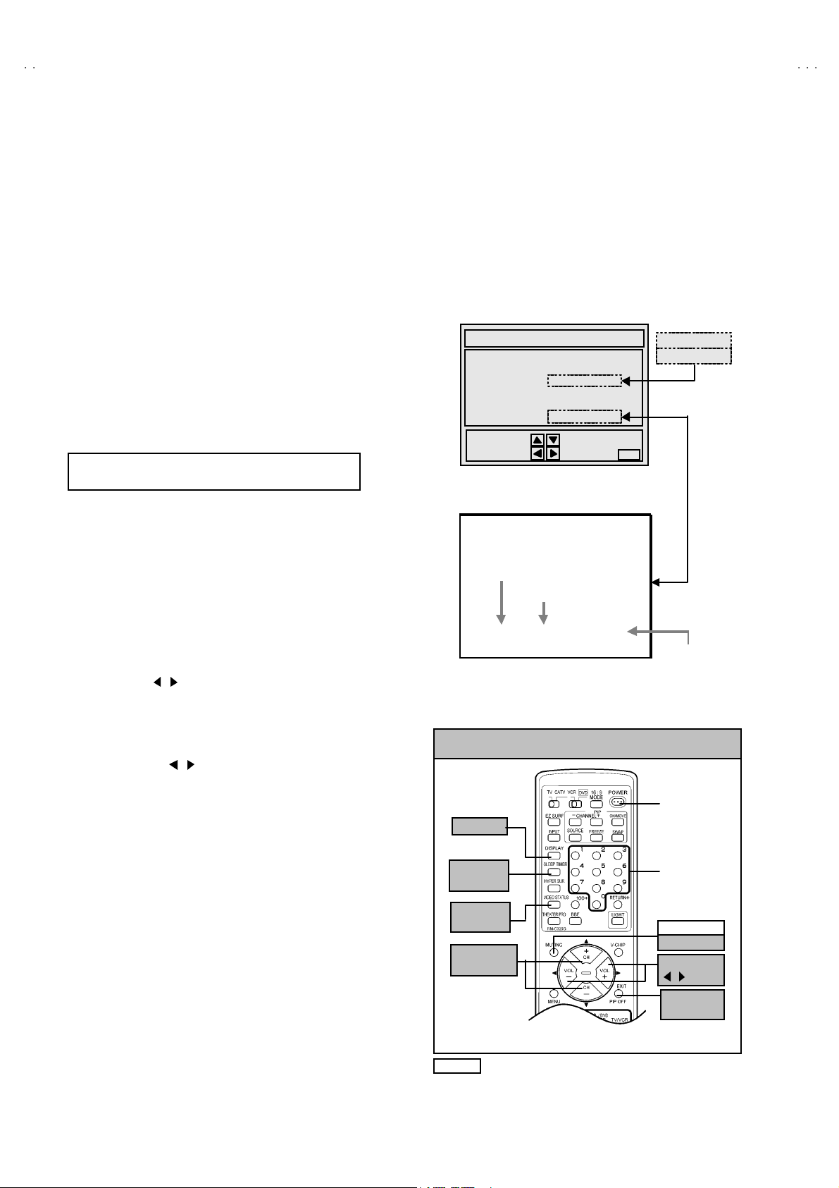
How to enter the SERVICE MENU.
1) Press th e SLE EP T IM E R key of th e re mo te c ontr o l uni t a nd set
the SLE EP TIME R for 「0 min」.
2) Be for e d is app ea r t he d ispl ay of SLE EP TIMER settings ,
si mu lt an eously pr ess the DISPLA Y key and V I DE O S TAT US key
of th e rem ot e co ntr ol u nit.
3) The SERVICE MENU screen will be displayed as shown Fig.1.
How to enter the 12. SYSTEM(SYS).
4) While the SERVICE MENU is dis played, select the
12.SYSTEM(SYS) item wit h FUNCTION (▼/▲) keys, and the
FUNCTION ( / ) keys is press ed, the screen will be displayed
as s hown in F ig.2 .
5) R efe r to th e SYSTEM ( SY ST EM CONSTA NT) TA BLE 1 and
ch ec k th e s ett ing i tems. If the val ue is di ff er ent , sel ect the set ting
item with the FUNCTION (▼/▲) keys an d adjust th e sett in g wit h
th e F UNCT ION ( / ) key s. ( T he let ters of t he se lecte d it em ar e
displayed in yellow. )
6) W hen ad jus tm en t h as c omp l ete d, t he val u es sto r e i nt o m em or y
IC a uto mati call y
7) Press the EXIT key to return the SERVICE MENU screen.
8) The n pr es s th e E XIT k ey ag ain to retur n th e n or m al sc r een .
(5) Receive the channel setting
Refer to the OPERATING INSTRUCTIONS (USER'S GUIDE) and
set the rece ive c h ann els ( Cha nn el s Prese t) as desc ribe d.
(6) User se tt in gs
Check th e us er sett in g it ems acc ordi ng to TABL E 2 .
Where thes e do no t agr ee , refer to th e O PE RA TIN G
INSTRUCTIONS (USER'S GUIDE) a nd set the ite ms as d escrib ed .
(7) SERVICE MENU setting
Verify what to set in the SERVICE MENU, and set whatever is
necessary (Fig.1) .
Refe r to t he SERVI CE ADJ USTM ENT f or s etting.
SELECT BY
OPERATE B Y EXIT BY
EXIT
Fig.1
12 .SY STEM(SYS
SETT ING ITEM NUMBER
SETT ING ITEM
***SYS01 VIDEO IN
SETT ING VALUE
Fig.2
KEY ASSIGNMENT OF REMOTE CONTROL UNIT
(RM-C325G)
POWE R
DISPLA Y
SLEEP
TIMER
NUMBER
VIDEO
TAT
MUTIN G
ME MO RY
FUNCTION
▲
FUNCTION
EX IT
PIP OFF
NOTE
lth ou gh d esi gn is di ff er ent as t hi s f ig ur e, each
remote controller has the same control function.
10
No. 52004
Page 11

A
3
A
3
A
3
12.SYS TEM(S YS) 【Syst em Con stant se tting】
Initial set ting v al ue Initial set ting v al ue
No. Setting item
AV-32F803
/Y
AV-32F703
AV-32F713
/Y
No. Setting item
/Y
AV-32F803
/Y
AV-32F703
AV-32F713
SY S01 VIDEO IN 04 03 SY S13 HYP SURR 01 01
SY S02 PIP 01 00 SY S14 16 :9 MD 01 01
SY S03 3D Y/ C 01 00 SYS15 HYP S CA N 01 01
SY S04 Y CV 01 01 SY S16 EZ SU R F 01 00
SY S05 CCD PCHK 01 01 SY S17 ID DISP 01 01
SY S06 PUR IT Y 00 00 SY S18 C OMPU LINK 01 01
SY S07 VM 01 01 SY S19 C CD 01 01
SY S08 NOISE CR 01 00 SY S20 VC HIP 01 01
SY S09 CLR TEM P 01 01 SY S21 VC HIP CA 01 01
SY S10 TH EATE R 01 01 SYS22 JVC L OGO 01 01
SY S11 TH EATE R PRO 01 01 SY S23 CMP IN 01 01
SY S12 BB E 01 01 SY S24 C XA1 87 5 00 00
Table 1
User setting
Setting item Setting value Setting item Setting value
Use remo t e control ler keys
POWE R
CHANNEL
VOL UME
TV/V IDEO
OFF
Cable-02
10
TV
DISPLA Y
VIDEO STAT US
H YP E R S U RROU N D
BB E
PIP SOURCE
Settings of MENU
PICTURE MENU INITIAL SETUP MENU
STANDARD
LA NG U AGE
TIN T C EN TER FR ONT PAN EL LO CK OFF
COLOR CEN TER V2 COMPONEN T-IN NO
PICTURE CENTER AUTO SHUT O FF OFF
BRIGHT CENTER CLOSED CAPTIO N OFF ( CC1 / T1)
DETAIL CENTER AUTO TUNER SET UP Unnecessary to set
COLOR TEMPERATURE LOW CHANNEL SUMMARY
NOISE MUTING ON V-CHIP OFF
SOUND ADJUST MENU SET LOCK CODE (000 0) U nn eces sary to set
BA SS
TR EBL E
BALANCE
MTS
CENTER
CENTER
CENTER
STEREO
XDS I D
CLOCK / TIMERS MENU
SE T CL OC K
MA NUA L
TIME ZONE : PA CI FIC
D.S.T. : OFF
ON / O FF TIMER
OFF
Table 2
OFF
DYNAMIC
OFF
ON
Cable-04
(AV -3 2F803/Y)
ENG
Se tting Ch ann el
Gu ar d ch an ne l : All OFF
ON
V-32F70
V-32F71
V-32F80
/Y
/Y
No. 52004
11
Page 12

A
V-32F703
A
A
Y
▼/
S
US
V-32F713
V-32F803
SERVICE ADJUSTMENTS
ADJUSTMENT PREPARATION
1. You ca n ma ke the n e ce ssa ry ad ju st me nts f or th is u n it with
either the Remote Control Unit or with the adjustment tools
and parts as given below.
2. Ad justment with the Remote Control Unit i s made on the
basis of the initial setting values, however, the new setting
values which set the screen to its optimum condition may
differ f rom th e initial settings.
3. Make sur e that AC power is sup pl ied co rr ect l y.
4. T ur n on the pow er for s et an d tes t eq ui p ment bef or e use , and
start t he adj ustm en t proced ures aft er w ai ti ng at least 30 min ut es.
5. U nl ess o the r wis e s pec ified, pr ep ar e t he mo st su itab le r ecep tion
or inp ut si gn al for adj ust m ent.
6. Never touch any adjustment part w hi ch ar e not spe cified in th e
list for t his adjustment - variable res istors, transformers, initial
set ti ng val u e, etc.
7. Pres etti ng b efore adj ustm en t.
Unles s ot her wise spec ified in t he a dj ustme nt i nstr uct i ons, p r es e t
th e f ollo wing f un ctions with th e re mo te c ont ro l un it :
User menu preset value
MENU ITEM PRES ET
VIDEO STAT US STA NDARD
BA SS, TREB LE, BA LANCE CENT ER
HYPER SURROUND OFF
TINT, COLOR,
PICTURE, BRIGHT , DETAIL
MTS ST ERE O
CENTER
ADJUSTMENT EQUIPMENT
1. DC voltmet er (or digital voltmeter)
2. Oscilloscope
3. Si gn al g en er at or (P attern g en er at or)[NTSC
4. Remote control unit
5. T V a ud io m ulti ple x si gn al ge ne rator .
6. F r equ enc y c ou nte r
KEY ASSIGNMENT OF REMOTE CONTROL UNIT
DISPLA
SLEEP
TIMER
VIDEO
TAT
FUNCTION
▲
]
(RM-C325G)
POWE R
NUMBER
MUTIN G
ME MO RY
FUNCTION
/
EX IT
PIP OFF
ADJUSTMENT ITEMS
%
CHEC K OF B1 POW E R SUPPLY
% ADJUSTM EN T OF VCO
MAIN VCO a djust me nt
SUB VC O ad ju stm ent
% ADJUSTM ENT OF R F. AGC
% ADJUSTMENT OF FOCUS
%
ADJUSTM ENT OF D EFLE CT ION CIRCUIT
V. HE IGH T / V. CENTER(4:3) adjustment
V. HEIGHT / L. LIN (16:9) adjust ment
H. POS I, H. SIZE & S IDE PIN [ (4 :3) & (16: 9) ] a djustm e nt
PIP DISP LAY POS I adjus tm ent ( AV- 32F8 03/Y)
% ADJUSTMENT OF VIDEO / CHROMA CIRCUIT
WHITE BA LAN C E( H ig h Li ght & Lo w L igh t) ad ju s tm ent
PIP WH IT E BA LANC E( H igh Li ght ) adj u stmen t ( AV -32F8 03/Y)
SUB B RI GHT a djust me nt
SUB CONTRAST adjustment
SUB COLOR adjustment
SUB TI NT adj us tment
12
% ADJUSTMENT OF MTS CIRCUIT
MTS IN PUT L EVE L adjust me nt
MTS SEP AR ATIO N adjustment
HOW TO CHECK THE HIGH VOLTAGE HOLD DOWN CIRCUIT
No. 52004
Page 13

A
3
A
3
A
3
ADJUSTMENT LOCATIONS
V-32F70
V-32F71
V-32F80
LED & POWER SW PWB
POWER
POWER
SW
S7701
IC62 1
AV SE L PWB
ON LY )
/Y
LED
D 770 1
(AV -3 2F803
T41 1
SUB VC O
SENSOR
I C7701
B B
ON LY )
/Y
/Y
CN 007
ONLY
SS
AV- 32F 803
3D Y/C SEP
MODULE
PI P P W B
IC70 2
MAIN PWB
me mo ry IC
IC20 1
FRONT CO NT RO L PWB
MENUVOL C H
J6 403 J6 402 J6 401
CN 600 7
DEG
F90 1
PW
WHT BL K
CN 600 6
IC91 1
FRONT
FRONT
CN 003
(AV -3 2F803
CN 500 1 CN 500 3
CN 400 2
PIP T UNER/IF
IC10 1
MAIN VCO
T11 1
TUNE R
TP-E
( )
HV
IC42 1
HVT
HVT
HVTHVT
CN 005
C
S1
E1
CR T EAR TH
(BRAIDED ASS'Y)
UPPER : FOC US
LOWER : SCREEN
B1
(TP-91)
13
B1
No. 52004
13
Page 14

A
V-32F703
A
A
(
)
V-32F713
V-32F803
CRT SOCKET PWB
TOP
PIP PWB
PIP T UNER
AV-3 2F80 3
IC
/Y ONLY
T41 11
SUB VC O
TP-R
TP-G
71
CN 300 4
AV SEL PWB
J5 501
J5 502
TP-E( )
(BRAIDED ASS'Y)
AV- 32F 803
3D Y/C SEP
MODULE
/Y
ONLY
TP-B
TP-E2
CN 30E2
CRT EARTH
TP-E1
1
CN 300 5
TOP
V
6
TOP
14
CN 400 2
No. 52004
J5 504
(AV -3 2F803
J5 503
ONLY)
/Y
CN 500 1 CN 500 3
(AV -3 2F803
ONLY)
/Y
Page 15

A
V-32F70
3
A
3
A
3
Y
▼/
S
US
V-32F71
V-32F80
BASIC OPERATION OF SERVICE MENU
1. TOOL OF SERVICE M ENU OPE RATION
Operate the SERVICE MENU with the REMOTE CONTROL UNIT.
2. In general, basic setting (adjustments) items or verifications are performed in the SERVICE MENU.
(1) V/C (S) ・・・・・・・ ・・・・・・・・・・・・・ ・・・・・・・・・・・・ ・・・・ This se t th e s etting values (a djustme nt values) of th e VIDEO/ CHROMA circuits .
(2) DEF (D)
(3) SOUND (A) ・・・・・・・ ・・・・・・・・・・・・・ ・・・・・・・・・・・・ This set the settin g valu es ( a djustm e nt values) of the AUDIO circuit.
(4) OTHERS (F)
(5) PIP (PIP) ・・・・・・・・・・・・・・・・・・・・・・・・・・・・・・・・ ・・ This set the s ettin g values(ad justment values) of th e PI CT URE-IN -PICTURE circu it.
(6) 3LY/C(LYC) / 3DY/C(DYC) ・・・・・・・ ・・・・・・・・・・・・ Thi s i s us ed w hen the 3 L( or 3D ) Y/C MOD E is ver i fi ed. [Do not adjust]
(7) LOW LIGHT・・・・・・・ ・・・・・・・・・・・・・ ・・・・・・・・・・・・ Thi s se ts th e setti ng v a lu es (adjust ment val ues ) of t he W HITE BAL ANC E circui t.
(8) HIGH LI GHT ・・・・・・・・・・・・・・・・・・・・ ・・・・・・・・・・・ This sets the s etting va lues ( a djust me nt valu es) of the WHITE BA LANC E circuit
(9) RF AFC・・・・・・・ ・・・・・・・・・・・・・ ・・・・・・・・・・・・ ・・・・ This is used when the RF AFC MODE is verified.
(10) VCO ・・・・・・・ ・・・・・・・・・・・・・ ・・・・・・・・・・・・・・・・・・ T his i s us ed w hen the I F VC O i s a dj ust ed .
(11) I2C BU S ・・・・・・・ ・・・・・・・・・・・・・ ・・・・・・・・・・・・・・・ T his i s us ed w hen ON/O FF of t he I2C BUS CTRL is set. [ Fixe d ON ]
(12) SY STEM (SYS) ・・・・・・・・・・・・・・・・・・・・ ・・・・・・・・・ This is us ed when the SYSTE M is ve rified. [F ixed value]
3. Basi c Op era tions of the SERVI CE M EN U
(1) Ho w to enter SERVICE MENU
Pre ss t he SLE EP T IM E R key and se t the SLE EP TIME R for
[0 MIN].
Then press the DI SPLAY ke y a nd th e VI DEO S T AT U S key o f
th e re mo te c ontro l u nit simu l tan eou sly, and th e SER VI CE
MENU screen will be displayed as shown below.
(2) Selection of SUB MENU SCREEN
In SERVI CE M ENU, press the FUNCTION
an y of th e SU B ME NU items . (The lett ers of the sel ec ted it em s
are dis pl a yed in yel l o w)
If an it em like to set up becomes ye l low, th e FUNCTION
/ key will be pushed and it will g o into the mode.
・・・・・・・ ・・・・・・・・・・・・・ ・・・・・・・・・・・・ ・・・
・・・・・・・ ・・・・・・・・・・・・・ ・・・・・・・・・・・
▲▲▲▲/▼▼▼▼
SERVICE MENU
1.V/C(S) 2.DEF(D)
3. SOUND(A) 4. OT HERS( F)
5.PIP(PIP) 6.3L Y/C(LYC)
7. LOW LIGHT 8.HI GH L IG HT
9. RF AF C 10.V CO
2
C BUS 12.SYSTEM(SYS)
11. 1
SELECT BY
OPERATE BY EXIT BY
EXI T
This se t th e s ettin g valu es ( a djustm e nt values) of the DEFLECTIO N circuit.
This is us ed when th e OTH ERS MODE is veri fied. [Do not adjust]
(PIP i s me ans as P i cture In Pictu re ) [ Only for AV -32F 8 03/Y]
[3L Y/C(LYC) =AV -32F703/Y, AV-32F 71 3/Y / 3D Y/ C(D YC)= AV- 32 F8 03/Y]
KEY ASSIGNMENT OF REMOTE CONTROL UNIT
(RM-C325G)
POWE R
DISPLA
key to selec t
SLEEP
TIMER
NUMBER
VIDEO
TAT
MUTIN G
ME MO RY
FUNCTION
▲
FUNCTION
/
EX IT
PIP OFF
Alth ou gh d esi gn i s di ff er ent as t his f igur e, e ach
NOTE
remote controller has the same control function.
FUNCTION ▲/▼ key
Select 1 .V/C ( S)~12.S YSTEM( SYS)
1.V /C( S)
2. DEF (D)
FUNCTION / key
Go into each SUB MENU
VI DEO/C HROM A
DEF LECT ION
SO UND
11 .I2C BUS
12.SYSTEM(SYS)
No. 52004
15
Page 16

A
V-32F703
A
A
V-32F713
V-32F803
(3) Method of Setting
For example, the operation in the case of setting up VIDEO/CHROMA is expressed below.
EX IT key
Retu rn to t he SERVICE
ITEM CONT ENTS
S01 BRIGHT
S02 PICTURE
S03 COLO R
S04 TINT
S05 DET AIL
S06 BRIGHT +-
S07 PICT + -
S08 C OLO R +-
S09 TINT +-
S10 DET AIL + -
ME NU MA IN
RF 4 : 3 STD LOW
S01 B RIGHT
S02 PI CTURE
S03 C OLOR
S04 T I NT
***
***
******
***
***
******
***
***
******
***
***
******
FUNCTION ▲/▼ key
Se le ct t he items fr o m
S01 t o S1 0.
FUNCTION / key
Increment or decrement
th e a djust ment val ue
(4) Others [Only for AV-32F803/Y]
If go in to the 9. RF A FC an d 1 0.VCO item s, the re will b e displ ay t he RF AFC M AIN scre en and VCO MA IN scr een .
The n pr ess th e FUNCTI ON / ke y, th e R F A FC SUB scr ee n and VC O S UB scr ee n is d is playe d.
10.VCO SUB 10.VCO MAIN
TUN ER MAI N
HIGH LE VEL
RE FEREN CE LEVE L
LOW LEVEL
SYN C Y ES
9.RF AFC MAIN MODE
FUNCTION
/ KEY
TUN ER SUB
HIGH LE VEL
RE FEREN CE LEVE L
LOW LEVEL
SYN C Y ES
9.RF AFC SUB
FUNCTION
TOO HI GH GOOD TOO LOW
TUN ER MA IN
AFC ON
FINE **
16
/ KEY
No. 52004
TOO HI GH GOOD TOO LOW
TUN ER SUB
AFC ON
FINE
**
Page 17

A
V-32F70
3
A
3
A
3
[
03
3
]
/
V-32F71
V-32F80
1.V/C(S)
R F 4 : 3 S T D L O W
S01 BRIGHT
2.DEF(D)
R F 4 : 3 S T D L O W
D 01 V F R EQ
3.SOUND (A)
A01 IN LEVEL
***
***
***
SERVICE M ENU ( M AIN M EN U)
SE RV IC E M EN U
1 .V/ C( S ) 2 .D E F(D )
3 .SO U N D (A ) 4. O T HE R S (F)
5 .PI P (P IP) 6 .3 L Y / C (LY C )
7.LOW LIGH T 8.HIGH LIG HT
9 .R F A FC 10 .V C O
2
C BUS 1 2.SY STEM( SYS )
11.1
SEL ECT B Y
O PE R AT E B Y E X IT B Y EXI T
7.LO W L IGH T
BRIGHT
***
***
***
***
8.HIGH LIGHT
***
***
9.RF AF C
TOO HIG H GOOD TOO LOW
T U NE R MA IN
A F C O N
FINE
***
4.OTH ER S( F)
F01
5.PIP ( PIP )
PI P01 B R IGH T
6.3L Y/C(LYC)
6.3D Y/C (DYC)
Do not ad just
***
***
Do not ad just
/Y
AV -32F7
[AV-32F803
Y
/ AV-32F 71
]
10.VCO
T U NE R M AI N
H IG H LE VEL
REFERENCE LEVEL
LOW LE VEL
SY N C NO
11.I2C BUS
I2 C B US O N
/Y
Do not ad just
12.SYSTEM(SYS)
LYC01
***
SY S 0 1 V ID E O IN
***
or DYC 01=AV-32F803
No. 52004
17
Page 18

A
V-32F703
A
A
V-32F713
V-32F803
INITIAL SETTING VALUE OF SERVICE MENU
1. Adjustment of the SERVICE MENU is made on the basis of the initial setting values ; ho wev er, the new setting values whic h
set the screen in its optimum condition may differ from the initial setting.
2. Do not change the initial setting values of the setting (adjustment) items not listed in “ADJUSTMENT”.
V / C M O DE
The item displayed “---“ is impossible to adjust.
RF STANDARD(4:3)
No . S ett ing ite m
AV-32F803
STD(4: 3) STD(16:9)
/Y
THE ATE R
(4: 3)
AV-32F703/Y,AV-32F713/
STD(4: 3) STD(16:9)
Y
THE ATE R
(4: 3)
EXTERNAL
AV-32F803
(S,CV)
AV-32F703
/Y
AV-32F713
COMPONENT
/Y
AV-32F803
/Y
AV-32F703
/Y
AV-32F713
S01 BRIG HT 64 --- --- 64 - -- - -- - -- - -- - -- - --
S02 PICTURE 60 --- --- 60 --- --- --- --- --- ---
S03 COLO R 50 --- --- 50 --- --- --- --- 49 49
S04 T IN T 68 - -- - -- 68 - -- - -- - -- - -- 68 68
S05 DETAIL 38 - -- --- 33 --- --- 40 35 45 40
S06 BRIGHT +- --- ±00 +01 - -- ±00 +01 - 01 - 02 ±00 ±00
S07 PICT+- --- -08 -10 --- -08 -10 ±00 ±00 ±00 ±00
S08 COLO R +- --- ±00 -03 --- ±00 -03 -02 -02 --- ---
S09 TINT + - --- ±00 -03 - -- ±00 -03 +12 + 05 --- ---
S10 DETAIL +- - -- --- ±00 --- - -- ±00 --- --- --- ---
Initial set ting v al ue
RF /EXT (S, CV) COM PON ENT
No . S ett ing ite m
STANDARD THEATER STANDARD THEATER
LOW HI GH LOW HIGH LOW HIGH LOW HIGH
S11 R CUT OFF 30 - -- --- --- - -- - -- --- - --
S12 G C U T OFF 30 - -- --- --- - -- - -- --- ---
S13 B C U T OFF 30 --- - -- - -- --- - -- --- ---
S14 R DRI VE 64 --- --- - -- - -- --- - -- ---
S15 B DRIVE 64 --- --- --- --- --- --- ---
S16 R CUT+- --- ±00 ±00 ±00 -10 --- --- ---
S17 G CUT+- ---
S18 B CUT+- ---
±
00
±00 ±00 ±00
S19 R DRV+- --- +05 +13 +07
S20 B DRV+- --- +06 -25 -09
±
00
±
00
±
00 --- --- ---
-10 --- --- ---
±
00 --- --- ---
±00
--- --- ---
S21NTSC MAT0303010102020101
S22 BLACK ST 03 --- 02 --- --- --- --- ---
S2 3 D CRE ST 01 --- 01 - -- - -- - -- - -- - --
S24 DCRSW 01 --- 00 --- --- --- --- ---
/Y
/Y
No . S ett ing ite m
Initial set ting v al ue
RF EXTERNAL COMPONENT
S2 5 AS Y SH R P 04 04 04
S2 6 BP F FO 00 00 ---
S27 KILR OFF 00 00 - --
S28 KIL R SE N 01 01 ---
18
No. 52004
Page 19

A
V-32F70
3
A
3
A
3
V-32F71
V-32F80
No. Setting ite m Init ial setting value No . Setting it e m Initial setting value
S29 R GB M UTE 00 S39 Y MUTE 00
S30 BLUE B 00 S40 SVM GAIN 03
S31 VID EO SW 03 S41 SV M PH 01
S32 C MP AB CL 00 S4 2 W PL 00
S33 OSD AB CL 00 S4 3 COL GM M 00
S34 OSD C ONT 08 S44 V1 GAI N 04
S35 SUB CONT 05 S45 AGC ADJ 63
S36 ABL GA IN 00 S46 VMOFF DE +03
S37 AB L PNT 03 S47 AP C CLK 01
S38 Y G AMMA 01
DE F M OD E
Initial set ting v al ue Initial set ting v al ue
No. Setting item
D01 V F R EQ 00 00 03 D18 W VM T BTM 00 01 00
D02 AF C GAI N 00 00 02 D 19 EW C R TOP 13 - -- 13
D03 H POS I 25 - -- 25 D20 EW CR T+- --- 00 ---
D04 H POSI+- --- 00 --- D21 EWCR BTM 08 --- 08
D05 V PHASE 00 --- 00 D22 EWCR B+- --- 00 ---
D06 V PH+- --- 00 --- D23 EW PARA 35 --- 35
D07 V S IZE 65 - -- 65 D24 EW PA RA +- - -- - 16 - --
D08 V SIZE +- - -- - 30 - -- D25 V EHT 00 - -- 00
D09 V CENTER 35 --- 35 D26 V EHT+- --- 00 ---
D10 V CENT+- --- 00 --- D27 H EHT 00 --- 00
D11 V S CORR 12 --- 12 D28 H EHT+- --- 00 ---
D12 V S CO+- --- 00 --- D29 TRAPEZ 36 --- 36
D13 V LIN 09 --- 09 D30 TRAPE Z+- - -- 00 ---
D14 V LIN+- - -- 00 --- D31 V AGC 00 00 00
D15 H SIZE 31 --- 31 D32 BLANK SW 00 00 00
D16 H SIZE+- --- 00 --- D33 VRMP BI 00 00 00
D17 WVMT TOP 00 01 00
AV-32F803/Y,AV-32F703
AV-32F713
RF
(4:3)
RF
(16:9)
/Y
/Y
EX T
(4:3)
No. Setting item
The item displayed “---“ is impossible to adjust.
AV-32F803/Y,AV-32F703
AV-32F713
RF
(4:3)
/Y
RF
(16:9)
/Y
EX T
(4:3)
SOUND MODE
No. Setting ite m Initial set ting v al ue
A01 IN LE VEL 10
A02 LOW SEP 32
A03 H I SE P 32
A04 SA PC 00
A05 BB E BASS
A06 BB E TRE - 04
±00
No. 52004
19
Page 20

A
V-32F703
A
A
V-32F713
V-32F803
OTHERS MODE (Do not adjust)
Se tting item s a r e n ot di splaye d.
Initial set ting v al ue Initial set ting v al ue
No. Setting item
AV-32F803
/Y
AV-32F703
AV-32F713
No. Setting item
/Y
/Y
AV-32F803
/Y
F01 OSD POS I 37 37 F15 VCSN 1 00 00
F02 OSD PREQ 90 90 F 16 VCSN 2 10 10
F03 CCD POSI 45 45 F17 VCSN 3 20 20
F04 CCD FREQ 93 93 F18 VC SN STP 02 02
F05 CCD CONT 05 05 F 19 VN DAT A +08 +08
F06 PUR WBCK 00 00 F 20 VM DAT B -08 -08
F07 PUR CONT 02 02 F21 VM DAT C -20 -20
F08 SN TYP E 01 02 F22 VM DAT D -32 -32
F09 YCSN T M 05 05 F23 VM DAT E 01 01
F10 YCSN E 05 05 F24 VMOFF TY 02 02
F11 YCSN F 16 16 F25 YC VM OFF 255 25 5
F12 YCSN G 32 32 F26 EZ SF T M 40 40
F13 VNR CHK 03 03 F27 XDSID TM 15 15
F14 VCSN T M 05 05 F28 FM TRAP 01 01
3L Y / C MODE (Do not adjust) [AV-32F703/Y and AV-32F713/Y]
No. Se tting it e m Initial set ting v al ue
AV-32F703
AV-32F713
/Y
/Y
LYC01 MO DE 04
LYC02 VENH 01
LYC03 PDSO FF 00
LYC04 CB 00
LYC05 VNLR 02
LYC06 GSEL0 00
LYC07 GSEL1 01
LYC08 COR 00
LYC09 TRAP 01
LYC10 CHT RAP 00
LYC11 CBPF 00
LYC12 ENHOFF 00
3DY / C MODE [AV-32F803/Y]
No. Setting it e m Initial set ting v al ue No . Setting ite m Init ial setting value
DYC01 D7-0 21 DYC15 D7-0 09
DYC02 D7-4 00 DYC16 D7-0 241
DYC03 D1-0 00 DYC17 D7-0 37
DYC04 D7-0 193 DYC18 D7-0 08
DYC05 D7-3 04 DYC19 D7-0 68
DYC06 RF CDL 02 DYC20 D7-0 48
DYC07 EXT CDL 02 DYC21 D7-0 08
DYC08 D7-0 42 DYC22 D7-0 51
DYC09 D7-0 36 DYC23 D7-0 200
DYC10 D7-0 34 DYC24 D7-0 74
DYC11 D7-0 01 DYC25 D7-0 236
DYC12 D5-0 22 DYC26 D7-0 00
DYC13 D7-0 00 DYC27 D7-0 00
DYC14 D7-0 15 DYC 28 3D YC 01
20
No. 52004
Page 21

A
V-32F70
3
A
3
A
3
V-32F71
V-32F80
PIP MODE (Do not adjust) [AV-32F803/Y]
No. Se tting item Init ial se tting value No. Setting ite m Initial set ting v al ue
PIP01 BRIGHT 00 PIP 28 MAT 01
PIP02 PICTURE 30 PIP29 YCOR 01
PIP 03 TINT I 42 PIP30 XFR EQF 01
PIP 04 COLO R 06 PIP 31 WTCHDG 01
PIP 05 R CUTO FF 00 PIP 32 C OLO N 00
PIP06 G CUT OFF 00 PIP 33 ACQNEW 00
PIP07 B CUTOFF 00 PIP34 DSTDET 01
PIP 08 R DRI VE 63 PIP 35 CRIBEOK 00
PIP 09 G D RIVE 65 PIP 36 F CBEOK 00
PIP 10 B DRIVE 65 PIP 37 N OC RID 00
PIP 11 L POS I 22 PIP 38 N ONSED 00
PIP 12 R POS I 15 PIP 39 PIP ADJ 08
PIP 13 UPR POS I 12 PIP40 BRI EXT 00
PIP 14 LW R POS I 11 PIP 41 PCT EX T 00
PIP15 PICT LCK 01 PIP42 TNT EXT 00
PIP16 SELDEL 00 PIP43 COR EXT 00
PIP17 AGCFIX 01 PIP44 R-D E XT 00
PIP18 AGCADST 00 PIP45 G-D EXT 00
PIP 19 AGC 07 PIP 46 B- D EXT 00
PIP 20 BL KIN VB 00 PIP 47 BR T COM P 00
PIP 21 BL KIN VR 00 PIP48 PCT COMP 00
PIP22 VSPDEL 00 PIP49 TNT COMP 40
PIP23 VSPISQ 01 PIP50 COR COMP 05
PIP24 RGBIN 00 PIP 51 R-D COMP 00
PIP 25 FRSEL 01 PIP 52 G-D COMP 00
PIP26 OUTFOR 00 PIP53 B-D COMP 00
PIP 27 UVPO LAR 00
NOTE The model AV-32F703/Y an d AV - 32F 713/Y do not have PIP f unction, but if memory data is out of range, some problems will be
h app en. Th en we ne ed to in put c orrec t da ta.
No. 52004
21
Page 22

A
V-32F703
A
A
(p
)
S
C
V-32F713
V-32F803
ADJUSTMENTS
CHECK OF THE B1 POWER SUPPLY
Item
Check of
B1 POWER
SUPP LY
ADJUS TMENT OF VCO
Measuring
Test point Adjustment part Description
instrume nt
DC Vo lt met er 【【【【B1 】】】】
Connector
in1 & pin3
TP-9 1(p in1)
TP-E (#):( pin3)
1. Recei ve th e blac k- a nd -w hit e sign al. (colo r off )
2. Connect th e DC vol tm et er to 【B1】co nnector pin【1 】( TP-91)
an d TP-E(#) (B1 connect or pi n 【3】).
3. Confirm that the voltage is DC134.5V±2V.
Item
MAIN VCO
adjust ment
SUB VCO
adjus tment
Only for
AV-32F803
Measuring
instrume nt
Signal
generator
Remote
control unit
TUNE R
HIGH LEVEL
REFERE NCE L EVEL
LOW LEVEL
SYNC :
MAIN
YE
Signal
generator
Remote
/Y
control unit
TUNE R
HIGH LEVEL
REFERE N
LOW LEVEL
SUB
E LEVEL
Test point Adjustment part Description
10 :V C O
MAIN VCO(T111)
[MAIN PWB]
Be sure t o in put the si g nal.
1. Receive the color bar signal.
2. En ter to th e S ERVIC E MENU mo de.
3. Se le ct t he 10:VCO m ode from th e S ERVICE MENU.
4. Pu sh th e FUNCTION / key, with the remote control unit
and s elect t he tuner t o MAIN .
5. Conf irm t ha t t he c o l or ch an ge f ro m HIGH LEVE L to LOW
LEVE L b y ad ju st the MAIN VC O at MAIN PW B, an d chec k the
SY NC is YES.
6. Adjust until REFERENCE LEVEL mark turns green.
GREE N
And th en confir m that th e SY NC is YE S again.
7. Press the EXIT key t o return t o SERVICE MENU.
10 :V C O
SUB VCO(T4111)
[PIP PWB]
Be sure t o in put the si g nal.
1. Receive the color bar signal.
2. En ter to th e S ERVIC E MENU mo de.
3. Se le ct t he 10:VCO mode from th e S ERVICE MENU.
4. Pu sh th e FUNCTION / key wit h th e remote co ntrol u nit,
an d s elect t he tun er t o SUB .
5. Conf irm t ha t th e c ol or c han g e f rom HIGH LEVEL to LOW
LEVE L by adjust the SUB VCO at PIP PWB, and check the
SY NC is YES.
6. Ad just u ntil REFERENCE LEVEL mark turns green.
And th en confir m that th e SY NC is YE S again.
7. Press the EXIT key to return to the SERVICE MENU screen.
GREE N
SYNC :
22
YES
No. 52004
Page 23

A
3
A
3
A
3
ADJUS TMENT OF RF AGC
Item
RF. AG C
adjust ment
Adjustment it em Initial set ting value
S45 AGC ADJ 63
Measuring
instrume nt
Signal
generator
Remote
control unit
ADJUS TMENT OF FOCUS
Item
FOCUS
adjus tment
Measuring
instrume nt
Signal
generator
Test point Ad justment part Description
S45:AG C ADJ 1. R eceive a bl ack and w hi t e sign al ( col or of f).
2. En ter to th e S ERVIC E MENU mo de.
3. Sele ct S45:AGC ADJ of the V/C M ODE.
4. Press the MUTING ke y an d turn of f th e co lor.
5. With the FUNCTION ke y t o get the noise in th e s cree n
pictu re ( zero s id e of s etting va lue).
6. Press the FUNCTIO N key several times and step when noise
disa ppe ars fr o m the scr een ( a t th at ti m e, no t to inc r ea s e the
val u e to o mu ch).
7. Cha nge to th e oth er ch an nels and make s ur e t hat th ere is n o
irregularity.
8. Press the MUTING ke y an d turn th e c o l or on .
Test point Ad justment part Description
FOCUS VR1
FOCUS VR2
[In HVT]
1. Receive the crosshatch signal.
2. While l oo ki ng a t th e scr een , a dj ust th e FOCU S VR 1 to th e
h oriz o nt al line w i ll be th inne st and shar p est cen ter h orizo nt al
line.
3. The n adj ust the FOCUS V R 2 to the ve rt ic al l ine looks s o fin e.
4. Make sure th at the pict ure is in f ocus ev en wh en the screen
g ets d ar kened.
V-32F70
V-32F71
V-32F80
ADJUS TMENT OF DEFLECTION CIRCUIT
Item
V. HEIG HT
V. CENTER
adjust ment
(4:3)
Scr een
size
Measuring
instrume nt
Signal
generator
Remote
control unit
Test point Adjustment part Description
D05 :V PHASE
D07:V SIZE
D 09: V CE NT ER
D11:VS CORR
D13:V LIN
92.0%
Picture
size
100%
1. Receive the crosshatch signal.
2. En ter to the SERVICE ME NU.
3. Se le ct t he D05:V PHASE of the 2 .D EF (D) ite m, a nd i t c hec ks
th at t he val u e of D05:V PHASE is 0.
4. Ad ju st t he ver tic al s cre en s i ze of the vi sibl e screen to p to
92.0% with the D07:V SIZE an d D0 9: V C E NT ER.
(NOTE)
Bottom is t o be loc ate d with 85%~95% range.
If vertical l in ear ity is not ev e n, adj us t the D13: V LIN. and D11: VS
CORR.
Adjustment it em Initial se tting v alue
D05 V PHASE 00
D07 V SIZ E 65
D09 V CENTER 35
D11 VS CORR 11
D13 V L IN 08
No. 52004
23
Page 24

A
V-32F703
A
A
V-32F713
V-32F803
Item
V. HEIG HT
V. LINEARITY
adjust ment
(16:9)
[B=B]
Measuring
instrume nt
Signal
generator
Remote
control unit
B
B
Adjustment it em Initial sett ing value
D08 V . SIZ E+ - -30
D14 V . LIN+- 00
Test point Adjustment part Description
D 08:V . SIZ E+ D 14:V . LIN E+ -
V. H EIG HT and V. C EN TER adjust ment of in th e 4: 3 s ize s h ou ld
b e fi ni sh ed.
5. Rec ei ve a bl ac k - and- wh it e sig nal (co lo r off).
6. Sele ct 16:9 asp ect mo de wit h remot e contr ol uni t.
7. Conf irm th at th e V- b l ank ing of the up per b ott om is equ al, and
its width is about 67mm.
8. If the con dition i s n ot c orre ct, ent er to the SE RVICE MENU.
9. Ad ju st t he D08:V. SIZ E+- an d D14: V . LIN +- to become the
blanki ng w id th to 67mm.
10. Press the EXIT key t o twice to r eturn th e normal screen.
(NOTE)
When yo u cha ng e t he vert ic al d eflect ion ad j ustmen t val u e in
the regular mode (4:3), readjust the 16:9 mode from beginning.
H. P OSI T IO N
H. SIZ E &
SI DE PI N
adjust ment
(4: 3)
Signal
generator
Remote
control unit
Scr een size 90.0%
Picture size 100%
D03:H .POS I.
D15:H . S IZ E
D23:EW PARA
D19:E WCR TOP
D21:E WCR BMT
V. H EIGHT an d V. P OSITIO N adj us tm e nt of in t he 4: 3 s iz e sh ou ld
b e fi ni sh ed.
11 . R eceiv e a cross hatc h sign al.
12. En ter to the SERVICE ME NU.
13 . Sele ct t he D03: H. POSI from 2.DEF (D) item.
14. Adjust by D03:H. POSI to become same size at both s ide.
15 . T he n ad ju st the horiz on tal s ize of th e vis ib l e sc r een at bot h
si de of ri g ht- an d-left to 90 % w it h the D1 5 :H. S IZ E .
16 . And adj u s t the ver ti cal lin e at bo th side to become straig ht line
by D23:EW PARA.
17 . Conf ir m th at the linea rit y of ver tic al lin e an d hor i zon tal size .
18. If it is necessary, readjust 14~17.
19. Pr ess the EX IT key t wice to return to the nor mal scr een.
(NOTE)
If it i s n ot s tr ai g ht t he ve rt ic al lin e at th e upp er an d bott om
cor n er , ad just th e upp er an d bot tom co rn er pi n sti ll mor e b y
D19:EWCR TOP and D21:EWCR BT M.
Adjustment it em Initial se tting v alue
D03 H. POS I
D15 H. SIZ E 30
22
D23 EW PARA 37
D19 EW C R TOP 08
D21 EW C R BMT 08
24
No. 52004
Page 25

A
V-32F70
3
A
3
A
3
(
)
(
)
(
)
V-32F71
V-32F80
Item
H. P OSI T IO N
H. SIZ E &
SI DE PI N
adjustment
(16:9)
Adjustment it em Initial sett ing v alue
D04 H. POS I+- 00
Measuring
instrume nt
Signal
generator
Remote
control unit
Scr e en si ze
Picture size
Test point Adjustment part Description
D04:H .POSI+D16:H . SIZ E+ -
D20:E WCR T+D22:EWCR B+D24:EW PARA+-
90.0%
100%
* V. SIZE / V. CENT ER adjustment sh ou ld b e f inished.
* H. SI Z E, H. POS ITION a nd SI DE PI N of i n the 4 :3 mode
ad justmen t sh ould be fin ish ed .
20 . Receive the crossh atch signal.
21 . Select 16:9 asp ect mo de wit h r em ot e co ntr ol uni t.
22. En ter to th e S ERVIC E MENU.
23. Conf ir m t hat th e bo th s id es of right -a nd- l ef t cross h atc h w i dt h to
b e th e value of 90%.
24. If it is not c orrect , adjust t he D16:H. SIZE +- an d D0 4:H.PO SI+- .
25. Conf ir m t hat th e seco nd vertica l line fr om l ef t edg e an d rig ht
ed ge to be str ai gh t.
26. If it is not straight, adjust the D24:EW PARA+-, D2 0: E WC R T + -
an d D22:EWCR B+-.
(NOTE)
When yo u chang e th e horiz on tal d eflectio n adjustment valu e in
the regular mode (4:3), readjust the 16:9 mode adjustment from
b eginn i ng .
D16 H. SIZ E+ - 00
D20 EW C R T+- 00
D22 EWCR B+- 00
D24 EW PARA+- -14
PIP DISPLAY
POSITION
adjustment
Only for
AV-32F803
/Y
Signal
generator
Remote
control unit
PI P scre en
PIP 11 : L POSI.
PIP 12 : R POSI.
PIP13:UPR POSI.
PIP 14 : LWR POS I.
X1
UPPE R PO SI.
* Main picture ’s V . SIZE , V. PO SITI ON, H . SIZE, H. POS ITION.
sh oul d be finish ed.
* Se t th e VIDEO STATUS to STANDARD.
1. Recei ve a bl ack - a nd- wh it e sig nal (co lo r off)
2. En ter to the SERVICE ME NU.
3. Se lec t t he 5: PI P(PIP) from SERVICE MENU.
4. Set the initial setting value of the PIP13:UPR POSI. with the
( / ) key of th e r e mo te c ont rol unit .
5. Ad jus t the PI P13:UPR POS I. so that the posi ti o n of t he P IP
screen edge of upper will be at X1 as shown.
6. Ad ju st th e c or resp on ding m odes of PI P14, PI P11 , PI P12 with
the same ste ps as 3~5 ab ove.
Adjustment it em
PIP13 UPR POSI 12 X1 80
Initial
se tting
value
Adjustment v alue
POSITION ( %)
X2
(LOWE R PO SI. )
Y1
LEFT POSI.
Y2
RIGHT PO SI .
No. 52004
PIP 14 L WR POSI 11 X2 80
PIP 11 L. POS I 22 Y1 80
PIP 12 R. POS I 15 Y2 80
25
Page 26

A
V-32F703
A
A
(R)
(G)
(B)
V-32F713
V-32F803
ADJUS TMENT OF VIDEO / CHROMA CIRCUIT
Item
WHITE
BALANCE
(Low Light)
adjus tment
Measuring
instrume nt
Signal
generator
Remote
control unit
Test point Ad justment part Description
[LOW LIGHT]
BRIGHT
** * *** * **
***
S01:B RIG HT
S11:R CUTOFF
S12:G CUTOFF
S13:B CUTOFF
SCREEN VR
[ in HVT]
1. Recei ve th e blac k an d w h it e sign al ( color off ) .
2. En ter to the S ERVICE MENU mo de.
3. Se le ct t he LOW LIGHT mode from the SERVICE MENU.
4. Conf irm th at th e in itial s etti ng value of S11:R CUTOFF, S1 2:G
CUTOFF, S13:B CUT OFF and S01: BRIGHT.
5. Disp lay a s in gle ho ri zo nta l lin e b y pr es sin g th e ①①①① key of the
remote control unit.
6. Turn t he scr een VR a ll the w ay t o t he l eft.
7. Tur n th e scr een VR gr adu all y to th e right fr o m th e l eft unt il
eith er o ne of the r ed, blu e o r g reen co lors ap pears f aintly.
8. Ad ju st t he t wo col o rs which di d not ap pea r un til th e sing le
horizontal line that is displayed becomes white using the ④④④④ to
⑨⑨⑨⑨ keys o f th e re mo te c ont r ol un it .
9. Tur n th e sc re en VR un ti l th e si ng l e h or i zon tal lin e is di splaye d
fain tly.
10. Press the ②②②② key to cancel the single horizontal line mode.
11. Ad ju st t he S0 1 :BR IG HT to become the black component
shines white slightly.
12. C onf ir m th at whet her th e c olor i ngr ed i en t of R , G, or B is v i si bl e
to th e bl ac k c o mp one nt, which shine s whi te sl ig htl y
13. W hen the c olor ingredien t ca n b e s een, tw o color s oth er th an a
visible color are adjusted, and it is made to look white.
[H.LI NE SCREEN]
REMOTE CONTROL UNIT
H.LINE ON EXITH.L IN E OFF
1
R C UTOF F B C UTO FFG CUTOFF
4
R C UTOF F B C UTO FFG CUTOFF
7
2
5
8
(NOTE)
The ③③③③ EX IT key is the cancel key for the W HITE BALANCE.
Adjustment it em Initial se tting v alue
S11 R CUT OFF 30
3
S12 G CUT OFF 30
6
S13 B CUT OFF 30
S01 BRIGH T 64
9
26
No.52004
Page 27

A
V-32F70
3
A
3
A
3
(R)
(B)
V-32F71
V-32F80
Item
WHITE
BALANCE
(High Light)
adjus tment
Measuring
instrume nt
Signal
generator
Remote
control unit
***
[WHITE SCREEN]
REMOTE CONTROL UNIT
H.LINE O N EXITH.L IN E O FF
1
R DR I VE
Test point Ad justment part Description
2
***
B DR IVE
S14:R DRIVE
S15:B DRI VE
3
1. Recei ve th e blac k- a nd -w hit e sign al ( col o r off ).
2. En ter to the SERVICE ME NU mo de.
3. Se lec t t he HIGH LIGHT mode in the SERVICE MENU.
4. Se t th e in it i al sett i ng valu e of S14:R DRIV E and S15:B DRIVE
with the ④④④④, ⑥⑥⑥⑥, ⑦⑦⑦⑦an d ⑨⑨⑨⑨ keys o f th e r em ot e c ontr o l un it.
5. Ad ju st th e s cr een u nti l it b ec om es wh it e using th e ④④④④ , ⑥⑥⑥⑥, ⑦⑦⑦⑦
an d ⑨⑨⑨⑨ keys of th e r em ot e contr o l uni t.
(NOTE)
The ③③③③ EX IT key is the cancel key for the W HITE BALANCE.
Adjustment it em Initial se tting v alue
S14 R DRIVE 64
S15 B DRIVE 64
PIP W HI TE
BALANCE
(High Light)
adjus tment
Only for
AV-32F803
4
R DR I VE B DR IVE
7
Signal
generator
Remote
control unit
/Y
5
8
6
9
PIP08:R DRIVE
PIP10:B DRIVE
1. Recei ve th e blac k- a nd -w hit e sign al ( col o r off ).
2. En ter to the SERVICE ME NU mo de.
3. Se lec t t he PIP08 : R DR IVE, PIP10 :B DR IVE, of t he 5.PIP( PIP)
SERVICE MENU.
4. Set th e corresp onding initial sett in g va lues with th e
FUNCTION ( / ) key of t he remote contr ol un it.
5. Ad jus t the PI P08:R DRIVE, PI P10:B DR IVE unti l th e s cr een
becomes white.
Adjustment it em Initial se tting v alue
PI P 08 R DR IV E 63
PI P 10 B DR IV E 65
No.52004
27
Page 28

A
V-32F703
A
A
(A)
y
g
(-)
V-32F713
V-32F803
Item
SUB BRI GHT
adjus tment
SUB
CONT RAST
adjus tment
adjus tment
Measuring
instrume nt
Remote
control unit
Adjustment it em
S01 BRIGH T 64
Remote
control unit
Adjustment it em Initial se tting v alue
S02 PI CTURE 60
Signal
generator
Remote
control unit
Adjustment it em Initial se tting v alue
S03 COL OR 50
Test point Ad justment part Description
S01:BRI GHT
Initial set ting v alue
S02:PICTURE
S03:C OL OR
1. Receive the broadcast and set the STANDARD mode.
2. Enter th e SERVICE ME NU.
3. Select S01: BRI GHT of the V/C(S) mode.
4. Set t he in it ial s ettin g valu e o f th e S01:BRI GHT with the
FUNCTION / key.
5. If the brigh tne ss is n ot t he best with the initial s ett ing val u e,
make fine adjustment of the S0 1: BR IG HT unt il yo u get th e
op ti mu m bright ness .
1. Receive the broadcast and set the STANDARD mode.
2. En ter th e SERVICE ME NU.
3. Select S02:PICTURE of th e V /C(S) mode.
4. Set th e in it i al setti ng val u e of th e S02:PICTURE with the
FUNCTION / key.
5. If th e c ontrast is not the bes t with the initial setting val ue, make
fin e adj us tm ent of th e S02:PICTURE unt i l yo u g et the op ti mu m
contrast.
[ Method of adjustment without measuring instr ument ]SUB COLOR
1. R eceiv e the b r oad c ast.
2. En ter th e SER VICE ME NU.
3. Select S0 3:COL OR of the V/C(S) mode.
4. Set the i niti al se tti ng value of th e S03:C OL OR with the
FUNCTION / key.
5. If the colo r is n ot th e b est with th e I nitial s etting valu e, make fine
ad justmen t of the S03:COL OR u nti l you g et t he op ti mu m color .
generator
Oscilloscope
Remote
control unit
Y
W
TP-B
TP-E(#### )
[CRT
SOCKET
PWB]
G
C
S03:C OL OR
R
M
0V
(+)
[ Method of adjustment using measuring instrum ent ]Signal
1. Input th e full fiel d c olor bar signal (7 5% w hi t e).
2. Enter to th e SERVICE MENU.
3. Enter to th e 9.RF AFC m ode and set the AFC t o OFF.
4. Select S03:COLOR of th e V /C(S) mode.
5. Se t the initial s etting valu e of t he S03:C OL OR with the
FUNCTION / key.
6. Con nect th e osc il losc ope be tw ee n TP-B and TP-E.
7. Adjust S0 3:COLOR and b ri n g th e va lue of (A) in the illustration
to +24V.
8. Reset th e RFAFC set ting pos itio n f rom OF F to ON .
B
28
No.52004
Page 29

A
V-32F70
3
A
3
A
3
y
g
V-32F71
V-32F80
Item
adjus tment
Measuring
instrume nt
Signal
generator
Remote
control unit
generator
Oscilloscope
Remote
control unit
Test point Ad justment part Description
[ Method of adjustment without measuring instr ument ]SUB TINT
1. Recei ve th e b road c ast.
2. Enter the SERVICE ME NU.
3. Select S0 4:TINT of the V/C(S) m ode.
4. Se t t he ini t ial se tti ng va l ue of t he S04:TIN T with the
FUNCTION / key.
5. If the tin t is not th e bes t with the ini ti a l set ti ng valu e, m ake fine
ad justmen t of the S0 4:TIN T until you get t he optimum ti nt.
Adjustment it em Initial se tting v alue
S0 4 TIN T 68
[ Method of adjustment using measuring instrum ent ]Signal
1. Inp ut th e ful l fi el d c olor b ar si gn al ( 7 5% whi t e).
2. Enter to the SERVICE MENU.
3. Enter to the 9.RF AFC m ode and set the AFC t o OFF.
4. Select S04:TINT of th e V/C( S) mod e.
5. Set th e i ni t ia l se tti ng val u e of th e S0 4:TINT with the
FUNCTION / key.
6. Con nect th e osc illosc ope be tw ee n TP-B and TP-E.
7. Adjust S04:T INT and bri ng the val u e of (B) in the illustration
to +26V .
8. Reset the RFAFC set ting pos itio n f rom OF F to ON.
TP-B
TP-E(#### )
[CRT
SOCKET
PWB]
S04:T INT
S04:T INT
Y
G
R
C
W
(B)
B
(-)
0V
(+)
M
No.52004
29
Page 30

A
V-32F703
A
A
V-32F713
V-32F803
ADJUS TMENT OF MTS CIRCU IT
Item
MTS IN PUT
LEVE L
Ad j ust men t
Measuring
instrume nt
Sopho meter
Remote
control unit
Test point Ad justment part Description
AUDIO
OUT R pin
A01 :IN LE VEL 1. Recei ve th e cros s-hatch si gn al (c ros s-h atch / 400H z)
2. Enter the SERVICE ME NU.
3. Se lec t t he A01:IN LEV EL of the 3:SOUND(A) MODE.
4. Verif y that the A01:IN LE VEL is set at its initial setting value.
5. Connect th e sopho m ete r t o AUDIO OUT R pi n .
6. Ad ju st th e MTS i npu t lev e l to 5 00mV(rms) b y A01 : IN LEVE L
with remote control unit.
7. Press the EXIT key to return to the SERVICE MENU screen.
MTS
SE PARATIO N
adjust ment
TV audio
mult iplex
signal
generator
Oscilloscope
Remote
control unit
R OUT
L OUT
[AUDIO OUT]
A02 : LOW SE P.
A03:HI SEP.
No. Setting item
A01 IN LEVEL 0~15 010
1. Inp ut th e ster e o L s ign al (300 H z) from the TV au di o m ulti ple x
si gn al g ener ator to th e ant enna ter m in al.
2. Connect an oscilloscope to R OUT pin of th e A UDIO OUT, a nd
disp l ay on e c ycle port ion of t he 300H z s i g nal .
3. Enter the SERVICE ME NU.
4. Se lec t t he A02: LOW SE P. of the 3:SOUND(A) mode.
5. Set th e i ni ti al s etti ng valu e of t he A02:LOW SEP. wit h the
FUNCTION ( / ) ke y.
6. Ad jus t t he A 02:LOW SE P. so that the stroke element of the
300Hz signal will become minimum.
7. Change the connection of the oscilloscope to L OUT pin of the
AUDIO O UT , and en lar ge th e volt age axis.
8. C ha nge th e s ign al to 3 kH z, an d s imil ar l y adjust th e
A03:HI SEP.
9. Press the EXIT key to return to the SERVICE MENU screen.
Variabl e
range
Initial set ting
value
Setting item
L- Chann el
signal wave for m
1 c ycle
30
R-C hannel
crosstalk por ti on
Mi n i m u m
No.52004
No .
A02 LOW SEP.
A03 HI SEP.
Variabl e
range
0~63
0~63
Initial set ting
value
03 2
03 2
Page 31

A
3
A
3
A
3
HOW TO CHECK THE HIGH VOLTAGE HOLD DOWN CIRCUIT
96.5
9
C525R53 5D5313
Q95
C533
5
(NC)
1. HIGH VOLTAGE HOLD DOWN CIRCUIT
After repairing the high voltage hold down circuit shown in Fig. 1.
Thi s ci r cuit sh all b e ch ecked to op er at e co rrect ly.
2. CHECKING OF THE HIGH VOLTAGE HOLD DOWN CIRCUIT
(1) Turn the power switch to on.
(2) As s h ow n i n Fig. 1, set t he r esistor b etwee n S1 c on nect or 2 an d 3 .
(3) Make sure t hat th e scr ee n pic ture disappe ar s.
(4) Temporarily unplug the power plug.
(5) Remove the resistor replac ed S1 connec tor 2 an d 3 .
(6) Ag ai n pl ug the p ow er plu g , make s u re th at t he no rm al pi ctur e is displ a yed on th e scr ee n.
Ω±
Ω±
ΩΩΩΩ
Ω±Ω±
19.3 k
B1
1
V-32F70
V-32F71
V-32F80
POWER
4
Fig. 1
2 1
R537
HEATER
T502
HVT
4
FR52
No.52004
31
Page 32

A
V-32F703
A
A
V-32F713
V-32F803
REPLACEMENT OF CHIP COMPONENT
!
CAUT IONS
1. Avoid heating for more than 3 seconds.
2. Do not ru b t he el ect ro des and t he resi st p ar ts of the p att ern.
3. W hen r em oving a c hi p par t, mel t th e s older adequ ately .
4. Do not reuse a ch ip p ar t afte r re mo vi ng it .
! SOLDERING IRON
1. Use a hig h ins ulati o n solder ing i r on with a t hin po in ted e nd of it .
2. A 3 0 w s older ing i r on is r ec ommended for easily r em ovi ng par ts.
! REPLACEMENT STEPS
1. How to remove Chip parts
#### Resi st o rs, ca pacitors , et c
(1) As s h own in t he f igur e, pu sh th e pa rt wi th tw ee zer s and
alte rn at ely m el t the s ol de r at each en d.
(2) Sh if t w i th tweez e rs and r emo ve th e ch i p p ar t.
#### T ran s istors, d io des , va ria bl e r esistors, et c
(1) Ap pl y e xt ra s o ld er to each le ad .
SOLDE R SOL D E R
2. How to install Chip parts
####
Resi st ors, ca pacitors , et c
(1) Apply sold er to the patt ern as ind icated in the fi g ure.
(2) Gr asp t he c h i p p art with twee zer s and pl ac e it on the s older.
The n hea t and me lt th e so lder a t b oth ends of t he chip part.
#### Tran s istors, d io des , va ria bl e r esistors, et c
(1) Apply sold er to the patt ern as ind icated in the fi g ure.
(2) Grasp the c h ip p art wit h t we ez e rs and p lace it on th e so l der .
(3) First s older lead A as indicated i n t he figu re.
A
(2) As s h own in t he f igur e, pu sh th e pa rt wi th tw ee zer s and
alte rn at ely m el t th e sol d er at each le ad . S hi ft an d r em ove t he
chip part.
(4) The n solder le ads B and C.
Note : A fte r re moving t he part , remove r emaining solder fr o m the
pattern.
32
No.52004
C
A
C
B
B
 Loading...