

Page 1
SERVICE MANUAL
COLOR TELEVISION
AV-27D503
BASIC CHASSIS
AV-27D503
AV-27D503
/S
/R
GE
CONTENTS
! SPECIFICATIONS ・・・・・・・・・・・・・・・・・・・・・・・・・・・・・・・・
!
SAFETY PRECAUT IONS
! FEATU RES ・・・・・・・・・・・・・・・・・・・・・・・・・・・・・・・・
! HOW TO IDENTIFY MODELS ・・・・・・・・・・・・・・・・・・・・・・・・・・・・・・・・
!
FUN CTIONS ・・・・・・・・・・・・・・・・・・・・・・・・・・・・・・・・
! SPECIFIC SERVICE INSTRUCTIONS ・・・・・・・・・・・・・・・・・・・・・・・・・・・・・・・・
!
SERVICE ADJUSTMENTS
!
PARTS LIST ・・・・・・・・・・・・・・・・・・・・・・・・・・・・・・・・
★ STAND ARD CIRCUIT DIAGRAM ・・・・・・・・・・・・・・・・・・・・・・・・・・・・・・・・
1
・・・・・・・・・・・・・・・・・・・・・・・・・・・・・・・・・・・・・・・・・・・・・・・・・・・・・・・・・・・・・・
・・・・・・・・・・・・・・・・・・・・・・・・・・・・・・・・・・・・・・・・・・・・・・・・・・・・・・・・・・・・・・・・
・・・・・・・・・・・・・・・・・・・・・・・・・・・・・・・・
・・・・・・・・・・・・・・・・・・・・・・・・・・・・・・・・・・・・・・・・・・・・・・・・・・・・・・・・
・・・・・・・・・・・・・・・・・・・・・・・・・・・・・・・・・・・・・・・・・・・・・・・・・・・・・・・・・・・・・・・・
・・・・・・・・・・・・・・・・・・・・・・・・・・・・・・・・・・・・・・・・・・・・・・・・・・・・・・・・・・・・・・・・
・・・・・・・・・・・・・・・・・・・・・・・・・・・・・・・・・・・・・・・・・・・・・・・・・・・・・・・・・・・・・・・・
・・・・・・・・・・・・・・・・・・・・・・・・・・・・・・・・・・・・・・・・・・・・・・・・・・・・
・・・・・・・・・・・・・・・・・・・・・・・・・・・・・・・・・・・・・・・・・・・・・・・・・・・・・・・・・・・・・・・・
・・・・・・・・・・・・・・・・・・・・・・・・・・・・・・・・・・・・・・・・・・・・・・・・・・・・・・・・・・・・・・・・
・・・・・・・・・・・・・・・・・・・・・・・・・・・・・・・・・・・・・・・・・・・・・・・・・・・・・・・・・・・・・・・・
・・・・・・・・・・・・・・・・・・・・・・・・・・・・・・・・・・・・・・・・・・・・・・
・・・・・・・・・・・・・・・・・・・・・・・・・・・・・・・・・・・・・・・・・・・・・・・・・・・・・・・・・・・・・・・・
・・・・・・・・・・・・・・・・・・・・・・・・・・・・・・・・
・・・・・・・・・・・・・・・・・・・・・・・・・・・・・・・・・・・・・・・・・・・・・・・・・・・・・・
・・・・・・・・・・・・・・・・・・・・・・・・・・・・・・・・・・・・・・・・・・・・・・・・・・・・・・・・・・・・・・・・
・・・・・・・・・・・・・・・・・・・・・・・・・・・・・・・・・・・・・・・・・・・・・・・・・・・・・・・・・・・・・・・・
・・・・・・・・・・・・・・・・・・・・・・・・・・・・・・・・・・・・・・・・・・・・・・・・・・・・・・・・・・・・・・・・
・・・・・・・・・・・・・・・・・・・・・・・・・・・・・・・・・・・・・・・・・・・・・・・・・
・・・・・・・・・・・・・・・・・・・・・・・・・・・・・・・・・・・・・・・・・・・・・・・・・・・・・・・・・・・・・・・・
COPYRIGHT © 2002 VICTOR COMPANY OF JAPAN, LTD.
・・・・・・・・・・・・・・・・・・・・・・・・・・・・・・ 2
・・・・・・・・・・・・・・・・・・・・・・・・・・・・・・・・・・・・・・・・・・・・・・・・・・・・・・・・・・・・
・・・・・・・・・・・・・・・・・・・・・・・・
・・・・・・・・・・・・・・・・・・・・・・・・・・・・・・・・・・・・・・・・・・・・・・・・
・・・・・・・・・・・・・・・・・・・・・・・・・・・・・・・・・・・
・・・・・・・・・・・・・・・・・・・・・・・・・・・・・・・・・・・・・・・・・・・・・・・・・・・・・・・・・・・・・・・・
・・・・・・・・・・・・・・・・・・・・ 4
・・・・・・・・・・・・・・・・・・・・・・・・・・・・・・・・・・・・・・・・
・・・・・・・・・・・・・・・・・・・・・・・・・・・・・・・・・・
・・・・・・・・・・・・・・・・・・・・・・・・・・・・・・・・・・・・・・・・・・・・・・・・・・・・・・・・・・・・・・・・
・・・・・・・・・・・・・・・・・・・・・・
・・・・・・・・・・・・・・・・・・・・・・・・・・・・・・・・・・・・・・・・・・・・
・・・・・・・・・・・・・・・・・・・・・・・・・・・・・・・・・・・・ 31
・・・・・・・・・・・・・・・・・・・・・・・・・・・・・・・・・・・・・・・・・・・・・・・・・・・・・・・・・・・・・・・・
・・・・・・・・・・・・・・・・・ 2- 1
・・・・・・・・・・・・・・・・・・・・・・・・・・・・・・・・・・
・・・ 4
・・・・・・
・・ 4
・・・・
・・・・・・・・・・・・・・ 6
・・・・・・・・・・・・・・・・・・・・・・・・・・・・
10
3
No.519 46
May 2002
Page 2
A
V-27D503
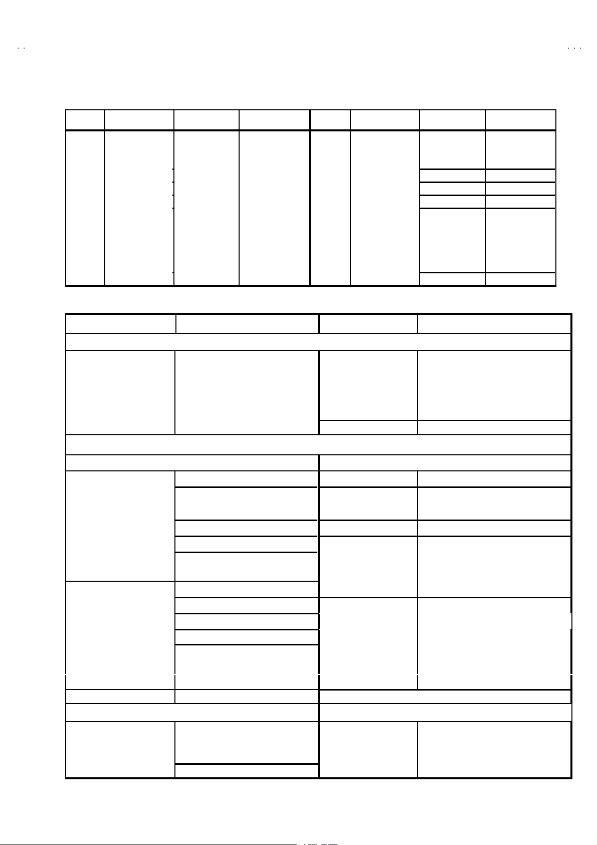
SPECIFICATIONS
Items Contents
Dimensions (W××××H××××D) 29-5/8 ”×23-1/4”×19- 1/2”
(752 mm×591mm×49 4mm)
Mass 71 .3Ibs (32 .4kg)
TV System and Color system
TV RF Sy stem
Color Sy st em
Sound System
TV Receiving Channels and Frequency
VL B and
VH Ba nd
UH F Ba nd
CATV Receiving Channels and Frequency
Low Band
Hi gh B and
Mid Band
Super Band
Hyper Band
Ul tra Ba n d
Sub Mid Band
TV/CATV Total Channel
Intermediate Frequency
Video IF Carrier
Sound IF Carrier
Color Sub Carrier 3.5 8 M Hz
Power Input 12 0V A C, 60Hz
Power Consumption 12 3W
Picture Tube 27” (68cm ) m easured di agonal l y, Full S quare
Hi gh V ol ta ge 29 kV±1.3 kV (at zero beam cur r ent)
Speaker 2”×4-3/4 ” ( 5×12 c m) Oval type ×2
Audio Power Output 5W+5W
Input termi nals
INPUT1 Video
S-Video
Audio (L,R)
INPUT2 Video
Component (Y,Pb,Pr)
Audio (L,R)
INPUT3 Video
(Front) Audio (L,R)
Audio Output 50 0mV rm s(-4dBs)
AV Compu link EX Input 3.5 mm mini jac k
Antenna terminal 75Ω (VHF/U H F ) Terminal, F-T ype Con nector
Remote Control Uni t RM-C251 (A A/R6/UM-3 batter y×2)
CCIR(M)
NTSC-M
BTS C (Multi Channel S ound )
(02~06) 5 4M Hz~88 MHz
(07~13) 1 74M Hz~216MH z
(14~69 ) 4 70M H z~80 6MHz
(02~06, A-8) by (02~06 &01 )
(07~13) b y (07 ~13)
(A~1) by (14 ~22 )
(J~W) by (23~36)
(W+1~W+ 28) by (37 ~64 )
(W+29~W +84) by (65 ~12 5)
(A8, A4~A1) by (01, 96~99)
18 0 Chan nel s
45 .75 MH z
41 .25 MH z (4.5M Hz)
1V p- p 75Ω (RCA pin jack)
Y :1 Vp-p p os itive ( neg ative sync pro vided , when terminated with 7 5Ω)
C: 0. 286Vp- p ( bur st s ig nal , when t ermin ated wi th 7 5Ω)
50 0mV rm s (-4dBs) , Hi gh I mpe dance (RC A pi n jack)
1V p- p 75Ω (RCA pin jack)
Y: 1 Vp-p p os itive ( negat ive sync p rovided, whe n ter mi nat ed wit h 75Ω)
PB/PR: 0.7Vp-p 75Ω
50 0mV rm s (-4dBs) , Hi gh I mpe dance (RC A pi n jack)
1V p- p 75Ω (RCA pin jack)
50 0mV rm s (-4dBs) , Hi gh I mpe dance (RC A pi n jack)
Low Im pedan ce (40 0Hz wh en m odul ated 100 %) (R CA pin jack)
(54MHz~80 4MHz)
De sign & speci f icatio ns ar e su bje ct t o cha n ge w itho ut notice .
2
No.51946
Page 3
A
3
SAFETY PRECAUTIONS
V-27D50
1. The desi gn of t his p ro du ct c ont ai ns spec i al h ar dw ar e, man y
ci rcu its and c o mp on ent s s peci al l y for saf ety pur p oses. F or
continued protection, no changes should be made to the
origina l des ign u nless a uth or i zed in wri ting by t he man ufactu re r.
Replacem en t par ts m ust be id ent ic al t o t hos e used in th e
origina l circui t s. S er vic e s ho ul d be perf or me d b y qu ali fied
p ers onnel o nly.
2. Al te rati on s of th e des i g n o r circu itr y of the p rodu cts s hou ld n ot
b e m ad e. A ny de sign alte ra tions or ad di ti o ns will vo id th e
manufacturer's warranty and will further relieve the
manu fac t urer of resp ons ibi lit y f or pe rs ona l i n ju r y or p r ope rt y
d am age r esult ing t heref rom .
3. M an y e lectrical an d mec h an ic al pa rt s in th e produ cts h ave
sp ecial s af ety-r elat ed charact eris tic s. Th ese charac teri sti cs ar e
oft en not e vid en t fr om visu al in spe ction no r can t he prote cti on
aff orde d by th em n ecess ar ily be o bta ined b y usi ng
replac ement compon ent s rated for h ig her vo l tag e, wa ttage, etc.
Replacem en t pa rt s wh ic h h ave t hes e sp ec ial s afet y
ch aracter istics a re i d entifi e d in th e par ts l ist of S ervic e man ua l.
Electrical components having such features are identified
by shading on the schematics and by (!!!!) on the parts list
in S erv ice manual. Th e us e of a su bst itu te re plac emen t whic h
does not have the same saf ety characteristics as the
reco mmen ded replac emen t pa rt sho wn i n the pa rts lis t of
Se rvi c e ma nu al m ay c ause sh ock, f ire, or o th er haz ards.
4. U se isola tio n tr an sf orme r when hot c hass is .
The chassis and any sub-chassis con tained in s ome products
are c onnect ed to on e side of th e AC p ow er l i ne . An i sola ti on
tr ansf or m er of ad equ ate cap acity sh ould be inser t ed bet ween
th e p rodu ct and t he AC p ow er s u pp ly p oi nt while p er for m i ng
an y ser vice on so me pr oducts when th e H OT ch assis is
exp ose d.
5. Don't shor t between the LIVE side ground and ISOLATED
(NE UTRAL) side ground or EARTH side ground when
repairing.
So m e mod el 's p ow er c irc ui t is par t ly dif feren t in the GND. Th e
diff er enc e of t he GN D is s h ow n by th e LI VE : (") side GND,
th e ISO LAT ED(NEU TRAL) : (#) side GND an d EAR T H : ( $)
si de GND. Don 't sho rt be tw ee n t he LIVE s id e GN D a nd
ISO LATE D(N EU TR AL) si de GN D or EART H si de GN D and
never measure with a measuring apparatus (oscilloscope etc.)
th e LI VE s ide GND a nd ISO LATED( N EUTRA L) si d e G ND or
EARTH sid e GND at the s ame time.
If above note will not be kept, a fuse or any parts will be broken.
6. If any re pa ir h as b ee n mad e to th e c h assi s , i t i s re c om m end ed
th at t he B1 se tti n g s h ou ld b e chec ked or ad jus te d (S ee
ADJUSTM ENT OF B 1 POW E R SUPPLY).
7. The hi g h v olt age a pplied t o the pictu re tu be mu st co nform wi th
that specified in Service manual. Excessive high voltage can
cau se an incr ease i n X- R ay e mi ssi on , arc in g an d possib l e
com po nent d am ag e, th eref or e op er atio n un der ex cess ive hi gh
vol ta ge c ond it i ons sh ou ld be ke pt to a min i mu m, or sh ou ld be
preve nt ed. I f seve re arc ing occu rs, r em ove th e AC p ower
immediately and determine the cause by visual inspection
(incor r ec t i nsta lla ti on , crac ked o r m el te d high vol tag e har ness,
p oor s olde rin g, etc. ). T o ma in ta in the pr op er mi ni m um l e v el of
sof t X- R ay e miss ion , c om p one nts in th e hi g h vol tag e ci r cuitr y
incl ud i ng the pi ctu r e tu be mu s t be the ex a c t r ep lac em en ts or
alte rn at ives a ppr o ved b y th e ma nuf actu r er of th e c o mp l ete
prod uct.
8. Do n ot c hec k high vol ta ge by d r awing a n ar c. U s e a hi gh
vol ta ge m ete r or a hi gh volt age p ro be wi th a VT VM . Disch arge
th e p ictu r e tu be bef ore a tte mp ti ng meter co nne cti on , b y
con nec ting a cl i p lead to th e gr ou nd frame a nd con n ec ti ng t he
oth er e nd of t he lead th roug h a 10 kΩ 2W resist or to t he ano de
bu tto n.
9. W hen s e rvice is r equ i r ed, ob s er ve th e orig inal l ea d dress .
Extra p r ecau ti on s h ou ld be giv en to assu r e cor re ct lea d dr es s
in the hi gh volta ge c ir cu it ar ea . W her e a sh ort ci r cuit ha s
occu rr e d, th ose c ompon en ts th at i nd ic ate ev i den c e of
overheating should be replaced. Always use the
manu fac t urer 's r epl ace m ent com p onents.
10 . Isolation Check
(Safety for Electrical Shock Hazard)
Af ter r e- a s sembling th e pr od uct , always pe rf or m an is o l ation
ch eck on th e expo sed m eta l p ar ts of th e c abi n et ( ant en na
ter m i na ls, vide o/a udio input and out put t er mi n al s, C on trol
knobs, metal cabinet, screwheads, earphone jack, control
sh afts, etc.) to be s ur e th e pr o duc t is saf e t o op er at e wi th out
d ang er of elect ri ca l shoc k.
(1) Di electric Strength Test
The is olat ion b etwe en the AC primary c ircu it and al l m eta l parts
exp osed t o the us er, par t icu l ar l y an y ex po sed metal p ar t h aving
a re tur n pat h to the ch as sis sh ou ld w i ths t and a volta ge of
11 00V AC ( r .m .s.) f or a p eri od of on e sec ond.
(. . . . Withstand a volta ge of 1100 V A C (r.m.s.) to an applian ce
rate d up to 1 20V , and 3 000V AC ( r .m. s.) t o an appl i anc e ra ted
200V or more, for a period of one second.)
Thi s m eth od of test r e qu ires a t es t eq uip ment n ot g en er ally
fou nd in t he servi c e t ra de.
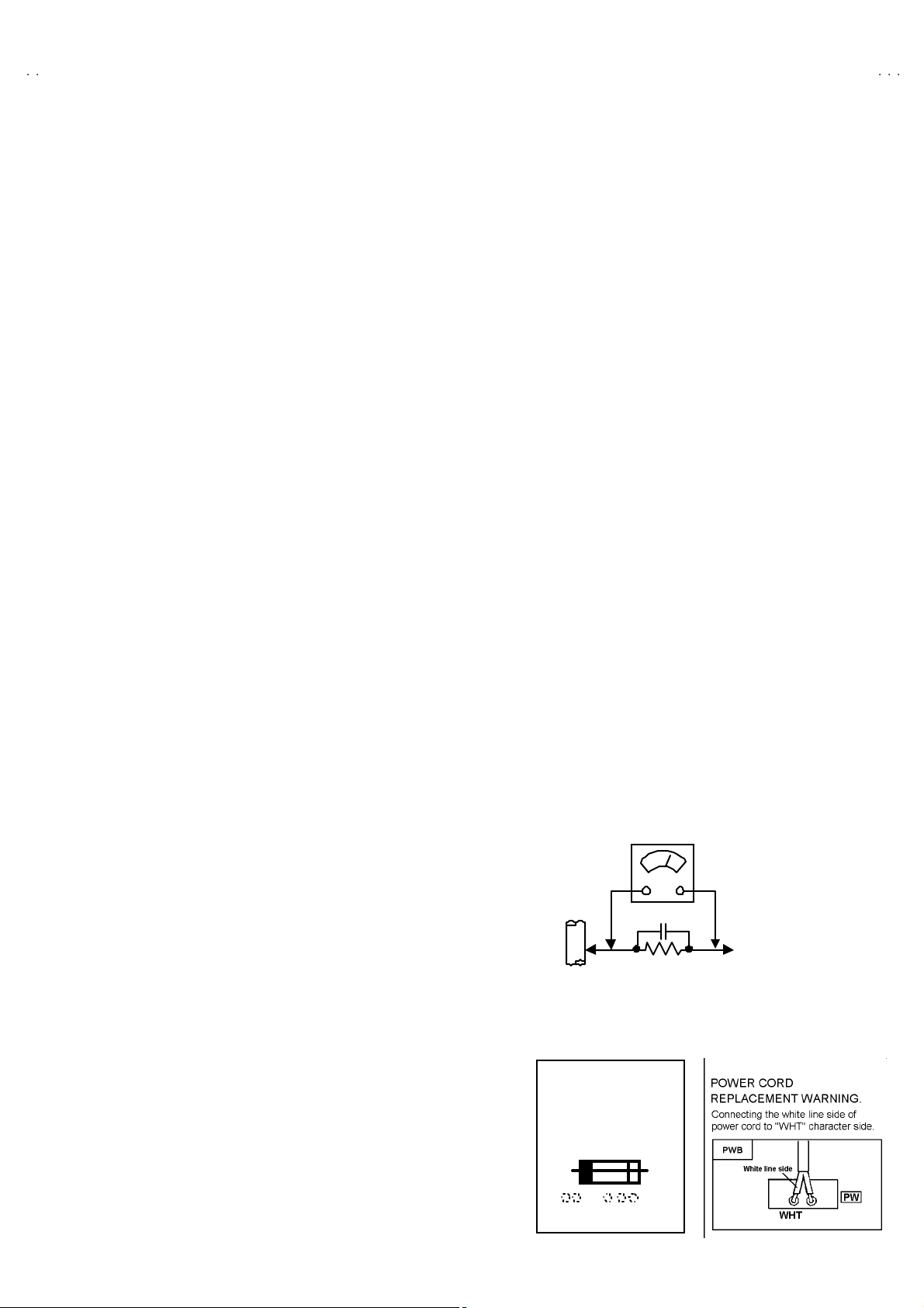
(2) Leakage Current Check
Plug t he A C line cord direct ly i nt o th e AC ou tlet ( do not u s e a
line is olation transf ormer during t his che ck.) . Using a " L eakage
Current Test er", m ea s ur e t he leakag e cur r en t fr om each
exp ose d m eta l par t of th e c a bi ne t, p ar tic ul ar l y an y expo sed
metal part having a retu rn path to t he ch assis, to a kn own good
ea rt h gr o und ( water p ipe, etc.) . A ny l ea k ag e c ur r en t must not
exce ed 0.5m A AC ( r .m. s.) .
Howev e r, in t ro pical a rea, this m ust no t e xc eed 0 .2m A AC
(r.m.s.).
"""" Alte rn at e Che ck M et hod
Plug t he A C line cord direct ly i nt o th e AC ou tlet ( do not u s e a
line isolation transformer during this check.). Use an AC
vol tm et er h av i ng 100 0 ohm s per vol t or m ore s en s iti vity in the
follo win g ma nne r. Connec t a 1 50 0Ω 1 0W resi s tor pa ralle l ed
by a 0.15μ F AC-typ e cap acitor b etwe en an exp ose d m eta l
p art and a k no wn go od earth gr ou nd (wate r pi p e, et c .).
Measu re th e A C vo ltag e acr os s th e r esist or wit h t he AC
voltmeter. Move the res istor connection to each exposed metal
part, particularly any exposed metal part having a return path to
th e ch assis , an d m ea sur e t he A C volta ge acr oss th e r esisto r.
Now, reve rs e the plu g i n t he A C out let a nd r ep e at e ach
measu rem ent. An y volta ge measu red m us t not exce ed 0.7 5V
AC (r.m. s.) . This corresponds t o 0 .5 mA AC ( r.m.s.).
Howev e r, in tr op ic al ar ea, this m ust n ot excee d 0.3V AC
(r.m.s.). This corr esp on ds t o 0 .2mA A C (r.m.s.).
AC VOLT METER
(HAVING 1000 Ω/V,
GOOD
EARTH
GR OUND
11 . High voltage hold down circuit check.
Af ter rep ai r of th e high vol t age h ol d d own c i r cuit, th is ci rcu it
sh all be c hec ked to op er ate cor rectly.
See item "Ho w to check the high voltage hold down
cir cuit".
This mark shows a fast
operating fuse, the
letters indicated below
show the r ati ng.
0.15μF AC-T YPE
1500Ω 10W
OR MOR E SENSIT IVITY)
PLACE THIS PROBE
ON E A C H EX PO SE D
ME T AL PA RT
A V
No. 51946
3
Page 4
A
V-27D503
FEATURES
"
New ch assi s d esign ena bles use o f a m ai n b oard w it h simplifi e d
circuit ry.
"
3 LIN E Di g it al Comb f ilt er Im pr oved p ic ture qual it y .
"
Full-square CRT (cathode ray tube) reproduces fine textured
pictu re i n ev er y d et ail.
"
With AV COMPU LINK EX te rminal.
" Closed -c aptio n b r oad casts can be viewed .
"
With AUD IO / VI DEO INP UT t erminal.
" S-VIDEO input terminal for taking best advantage of Super VHS.
"
Au di o out put ter m i na l.
"
I2C bus control ut ilizes single chip ICs.
" Be caus e built-in the BBE ci rc uit impr oved th e sou nd of
conversation.
"
DVD dec k outp ut ca n i npu ts to c ompon en t v ideo sign al inpu t
terminal.
"
The hyper-su rround system marks a reproduction of the acoustic
eff ects in a the ate r with str o ng ap peal.
"
Bec aus e of bu ilt- i n 2 tu ner & P IP ci r cuit, displ ays p lur al pr og r am s
on th e scr e en at t he sam e ti me .
"
Built-in V-CHIP,V-CHIP CAN system
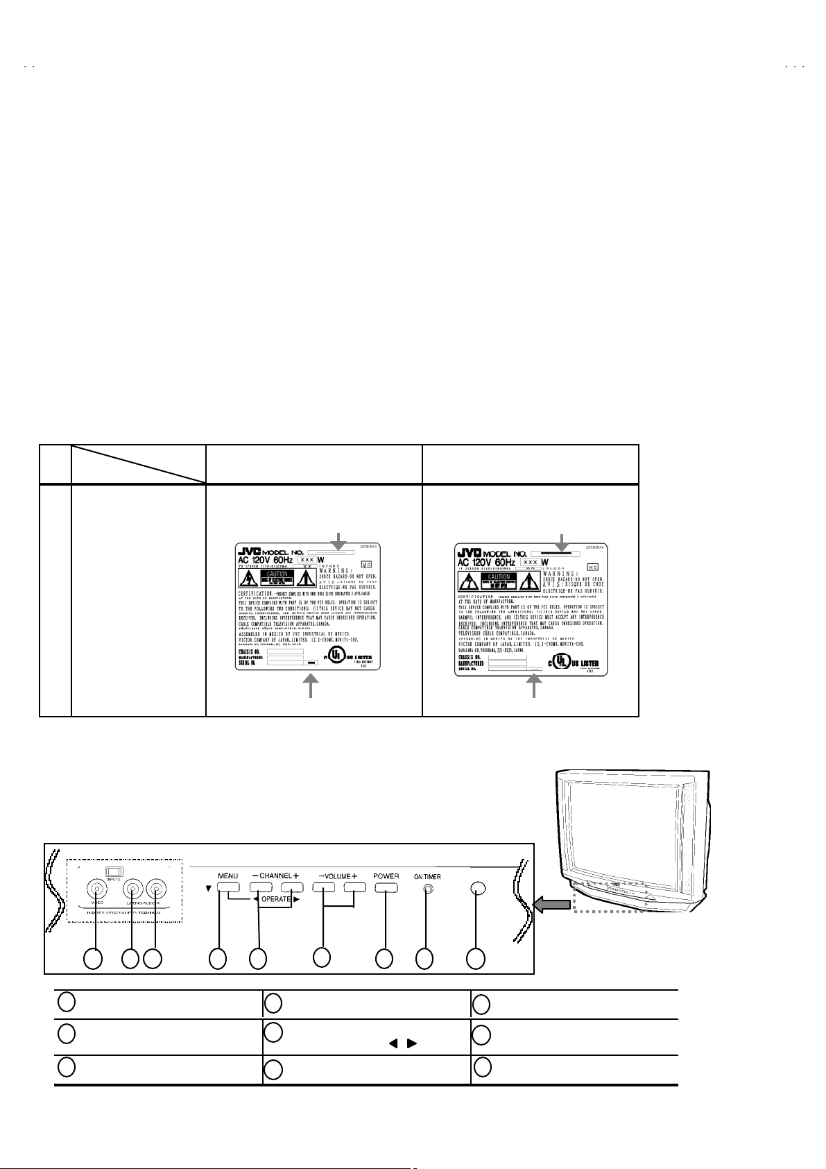
HOW TO IDENTIFY MODELS
How to recognize from the appearance of the model concerned is written below. Please distinguish from several
con tents c u rr e ntly p rint ed on th e r at in g l a bel
!
Parts nam e
RATING L ABE L GQ3 0032 -0 01A-A
!
MODEL
AV-27D503/S AV-27D503/R
←←←←
INDICATED AV-27D503 INDICATED AV-27D503
INDICATED““““S””””
Ⅰ
Ⅰ
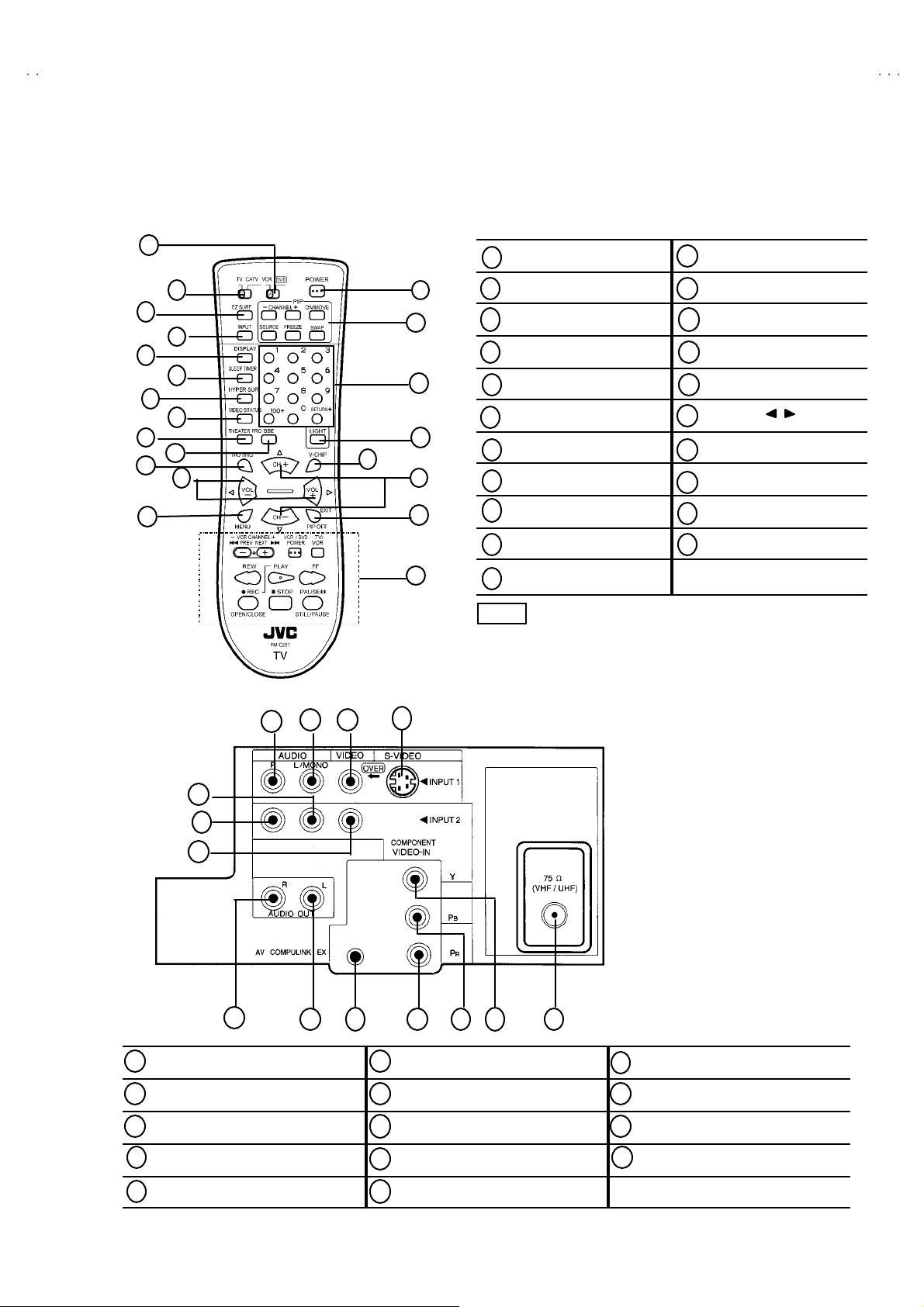
FUNCTIONS (
■
FRONT PANEL
1 2
1
INPUT3 VIDEO terminal MENU button POWER button
2
INPUT3 AUD IO L terminal
3
INPUT3 AUD IO R termina l VOLU ME -/+ butto ns REMOTE CON TROL sens or
3
ⅠⅠ
4 5
)
6 7
4
CHANNE L - /+ bu tt ons
5
MENU O PER A T E / buttons
6
8 9
INDICATED
7
8
ON TIMER lamp
9
““““R””””
4
No. 51946
Page 5
A
3
Ⅱ
Ⅱ
FUNCTIONS(
■■■■
REMOTE CONTROL UNIT (RM-C251)
20
21
2
3
4
5
6
7
8
9
10
11
ⅡⅡ
)
16
V-27D50
POWER key MENU key
1
EZ SURF key PI P keys
1
13
14
15
17
2
INPUT key CHANNEL keys
3
DISPLAY key LIGHT key
4
SLEEP TIMER key
5
HYPER SUR. key CH-/+( /
6
VIDEO STATUS key EXIT/PIP OFF key
7
THEATER PRO key V C R CO N TRO L key
8
12
13
14
15
V-CH IP key
16
17
18
19
)keys
12
■■■■
REAR PANEL
6
7
BBE key VCR / DVD
18
19
1
5
32
4
9
MUTING key TV / CATV
10
VOL-/+(
11
The CH-/+ and VOL-/+ keys operate CHANNEL and
NOTE
VOLUME normally.
Thes e keys are also used to navigate MENU system.
▼/▲)
keys
20
21
sw it ch
switch
8 9
1
INPUT 1 A UDIO R t erm inal INPUT 2 AUDIO L/MONO terminal COMPONENT Y terminal
2
INPUT 1 AUDIO L/MONO terminal INPUT 2 VIDEO terminal COMPONENT PB terminal
3
INPUT 1 VIDEO terminal AUDIO OUT R terminal COMPONENT PR terminal
4
INPUT 1 S-VIDEO
5
INPUT 2 AUDIO R terminal AV COMPULINK EX terminal
10
11 12
6
7
8
9
AUDIO OUT L terminal VHF / UHF terminal
10
13
No. 51946
14
11
12
13
14
5
Page 6
A
V-27D503
C
SPECIFIC SERVICE INSTRUCTIONS
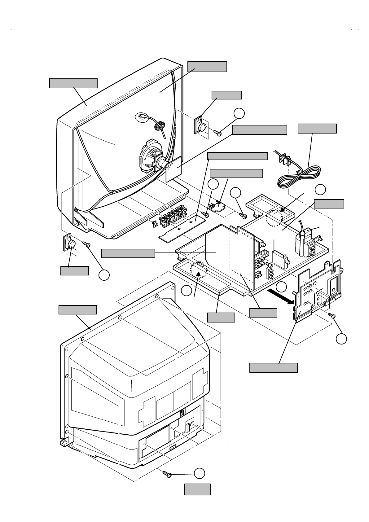
DISASSEMBLY PROCEDURE
REMOVE THE REAR COVER
"
U np lug the po we r plu g.
!!!! "
"
1. Rem ove th e 12 screws marked
2. Remove the rear c over t oward you.
* When r ei nst al l in g th e re ar c o v er , c ar efu lly pu s h it i nw ar d af ter
inserting the chassis into the rear c over groove.
""
as sh ow n i n F ig .2.
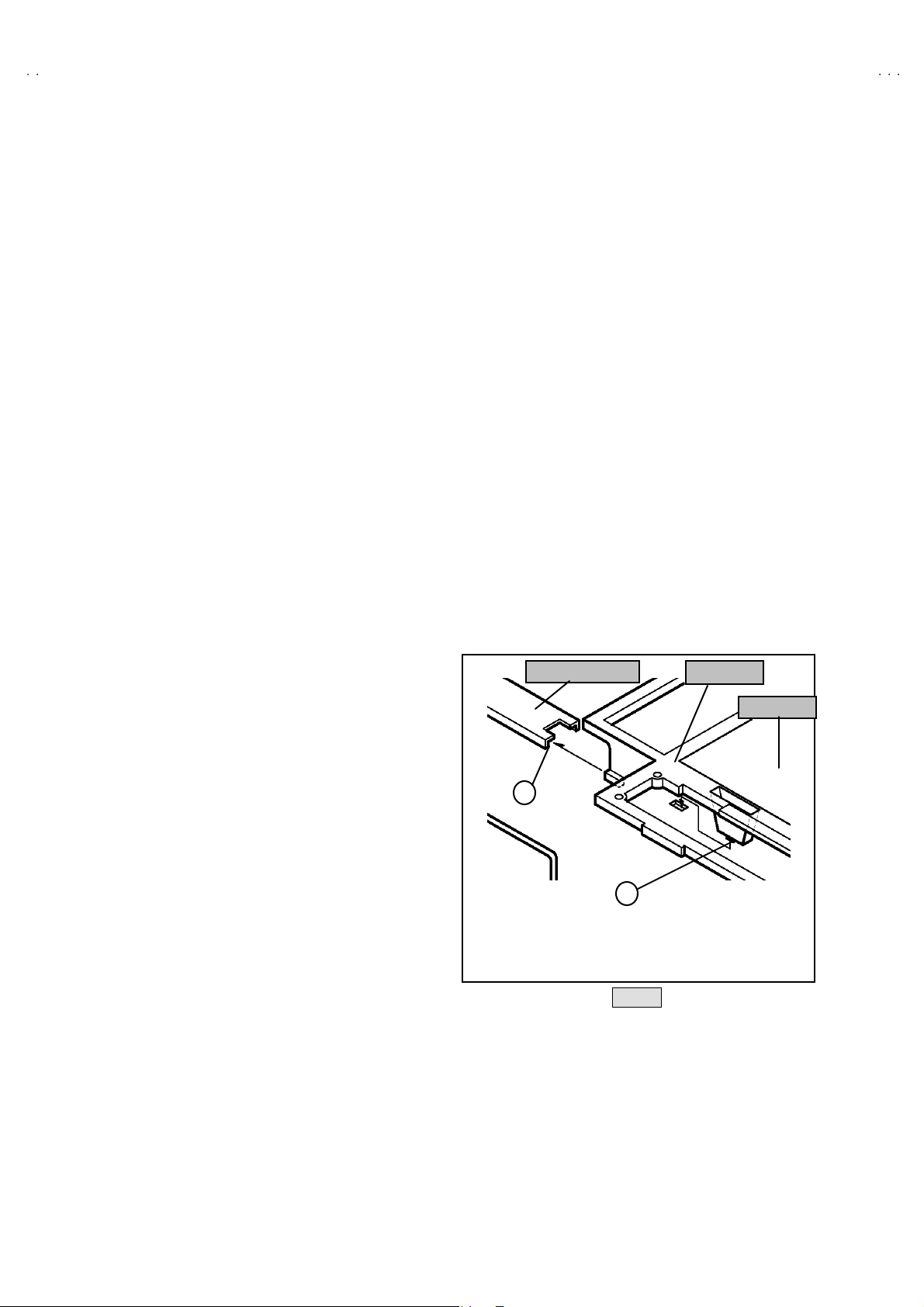
REMOVING THE CHASSIS
" After removing the rear cover.
1. Slight l y r aise th e bo th si des o f th e c hassi s by ha nd a nd remov e
the 2 claws marked #
th e ch assi s fr o m t he front cabinet .
2. Dr aw th e chas sis b ackwar d alo ng th e r ai l m ar ked
the arrow direction marked
(If nec ess ar y , take off the w ire cl am p, c onn ec t or’s e tc .)
* When con ducti n g a chec k with p ower s u ppl i ed , b e sure t o
con firm th at the CRT earth wire is c onn ec te d t o t he CRT
SOCKET PW B and th e M AIN P W B.
# ( Fig. 1 and Fig .2) un der th e bo th sid es of
##
$$$$
(Fig.1) in
%%%%
(Fig.2.).
REMOVING THE TE RMINAL BOARD
"
After removing the rear cover.
"&
"&
1. Rem ove th e 4 screws ma rked
2. W hen you pu l l ou t th e T E RMIN AL BOARD, i t ca n b e re mo ved .
"&"&
(Fig.2)
"'
"'
"'"'
.
REMOVING THE SPEAKER
" After removing the re ar cover and chassis.
1. R em ove t he 4 screws ma rked *"
2. Follow th e s ame s t eps when r em ovin g t he oth er h and spe ake r.
*"(Fig.2.)
*"*"
CHECKIN G THE MAIN PW BOARD
1. To ch eck the ba cks ide of t he MA IN PW Boar d.
(1) Pull out the ch assis. ( Refer to REMOVIN G TH E CHAS SIS ).
(2) Erect the chassis vertically so that you can easily check the
backside of the MAIN PW Board.
[CAUTION]
• When erect ing th e ch assi s, be caref ul so th at the r e will be n o
con tact in g with ot her P WB.
• Before turning on power, make sure t hat the CRT earth wire and
oth er c o nn ecto rs are p ro perly c o nn ecte d.
WIRE CLAMPIN G AND CABLE T Y ING
1. Be sure t o clamp th e wir e.
2. Never rem o ve th e cable ti e used f or tyi ng the w i re s to gethe r.
Sh oul d it be i n adv e rt ent l y rem ove d, be su r e to tie the wires with
a n ew c able tie.
FRONT CABINET
CHASSIS
MAIN PWB
REMOVING THE FRONT CONTROL PW BOARD
"
After removing the re ar cover and ch assis.
1. Rem ove t he 2 screws marked
2. Then r emo ve the FRONT CONTROL PWB.
((((
(Fig.2).
REMOVING THE FRONT AV IN PW BOARD
"
After removing the re ar cover and ch assis.
1. Rem ove t he 2 screws marked
2. Then r emo ve the FRONT AV IN PW B.
))))
(Fig.2 .).
B
Fig. 1
6
No. 51946
Page 7
A
3
FRONT CABINET
V-27D50
PICTURE TUBE
SP EAKER
H
SP EAKER
REAR COVER
AV SELECTOR PWB
H
B
CLAW
CRT SOCKET PWB
FRONT CONTROL PWB
FRONT AV IN PWB
FRONT AV IN P WB
F
G
CHASSIS
PIP PW B
TUNER
POWER CORD
CLAW
B
MAIN PWB
FBT
D
AV JAC K
TERMINAL BOARD
E
A
Fig.2
No. 51946
7
Page 8
A
V-27D503
C BUS
S)
)
SYS0
O
MEMORY IC REPLACEMENT
1. Memory IC
This TV uses me mor y IC .
Thi s m em or y IC st ores d ata f or pr oper o pera tion of the vide o and deflec ti o n cir cuits.
When r ep la c ing t he mem or y IC , be s ur e to us e an IC co nta ini ng th is ( i ni ti a l value ) d at a.
2. Memory IC replacement procedure
(1) Power off
Switch off th e pow er an d di s con nec t th e p ow er c o rd fro m t he out let.
(2) Replace the memory IC
Be sure t o use a memory I C written with the initial settin g data.
(3) Power on
Con nect th e power cord to th e o utlet and switch on the power.
(4) Con fir m th e sy st em const an t value
"
12 .S YSTEM ( SYS ) do not a djust nor m al l y.
"
The adjustment should not be done without signal.
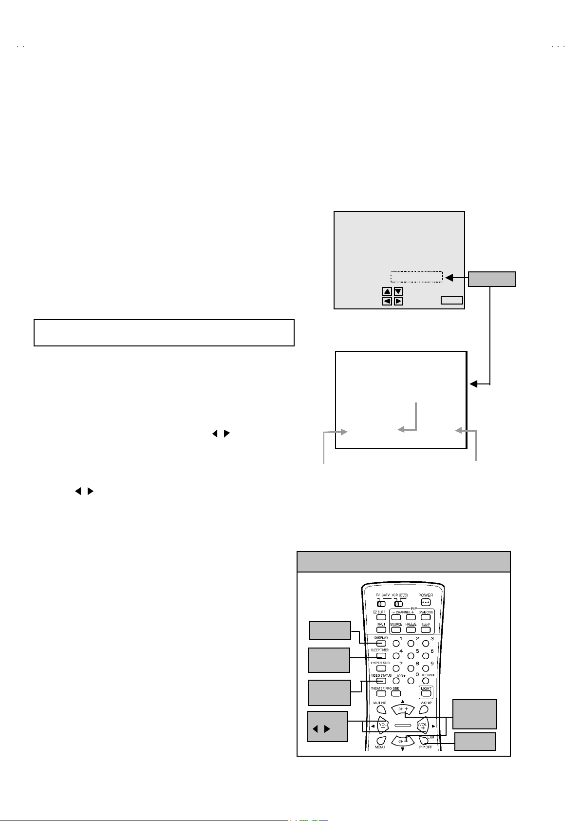
! Ho w t o ent er t he SY ST EM (SYS ).
1) Press the SL EEP TIMER ke y and se t SL EEP TIMER f or 「0 min」.
2) Be fore di sap pe ar th e displ a y of S LEE P TIM ER set tings , si mu l tan eous ly
press th e DISP LAY key an d VIDEO STA TUS ke y of th e rem ot e c ont rol
un it.
3) The SER V ICE M ENU s cree n of Fig.1 i s d isp layed .
4) While the SERVICE MENU is displayed, select t he SYSTEM(SYS) item
wi t h ME NU ▼/▲ (CH-/+) keys, and the MENU / (VOL-/+) keys is
pressed, the screen will be displayed as shown in Fig.2.
5) Refe r to the SY ST EM (SY STEM CONST A NT) TAB LE 1 a nd ch eck t he
setting items. If the value is different, select the setting item with the
ME NU ▼ / ▲ (C H -/ +) keys and adj u s t the sett in g with th e
MENU / (VOL-/+) keys. (The letters of the selected item are
displayed in yellow. )
6) W hen adjustment has co mp le te d, t he v al ues sto re in to m emor y IC
automatically
7) Press the EX IT key t wice to r eturn th e n orm al scr een.
SETTING N o
SE RVICE MENU
SERVICE MENU
1.V/C(S) 2.DEF(D)
3. SOUND(A) 4 .OTHERS( F)
5.PIP(PIP) 6.3L Y/C(LYC)
7.LOW LIGHT 8.HIGH LIGHT
9.RF AFC 10.VCO
12.SYSTEM(SY
11.I2
SELECT BY
OPERATE BY EXIT BY
Fig.1
12 .SY STEM(SY S
SETTING ITEM
1 VIDE
Fig.2
EXIT
***
SETTING VAL UE
Verifi ed
KEY ASSIGNMENT OF REMOTE CONTROL UNIT
(5) Rec eiv e channel setting
Refe r to the OPERA TING IN S TRUCTIONS ( USER'S GUID E) and set
th e r ec e i ve ch annel s ( Cha nn els Pres et) as des crib ed.
DISPLAY
(6) User settin gs
Check th e us er s ett ing it ems ac c ordi ng to TABL E 2 .
SLEEP
TIMER
Wher e thes e d o not agree, r ef er to th e OP ERATIN G I NSTRUC TION S
(USER'S GU IDE) an d s et t he it ems as des crib ed.
VIDEO
STA TUS
MENU
▼/▲
EXI T
(7) SERVICE MENU setting
Ve rif y what to s et i n th e SER VI CE M EN U , and s et what ever is
MENU
/
necessary. (Fig. 1) Ref er to the SERV ICE ADJUSTMENT f or setting.
8
No. 51946
Page 9
A
3
TABLE 1 (System Constant setting)
No Setting item Variable range
SY S01 VIDEO 0~4 3
SY S02 PIP 0~1 1
SY S03 3D Y/ C 0~1 0
SY S04 Y CV 0 ~1 1 SY S16 EZ SURF 0~1 1
SY S05 CCD P CHK 0~1 1 SY S17 ID D ISP 0~1 1
SY S06 PUR ITY 0 ~1 0 SY S18 COMP U LINK 0~1 1
SY S07 VM 0 ~1 0 SY S19 CCD 0~1 1
SY S08 NOISE CR 0~1 0 SYS20 VCHIP 0~1 1
SY S09 CLR TEM P 0~1 1
SY S10 THEATE R 0 ~1 1
SY S11 THEATE R PRO 0~1 1
SY S12 BBE 0~1 1
Initial setting
value
No Settin g ite m Variabl e ra nge
SYS 13 HYP S URR
SY S14 16:9 MD
SY S15 HYP S CA N
SY S21 VCH IP CA
SY S22 JVC LOGO
SY S23 CMP IN
SY S24 CXA1 87 5
0~1
0~1
0~1
0~1
0~1
0~1
0~1
TABLE 2 (User setting)
Setting item Setting value Setting item Setting value
Use remo t e co ntrol ler ke ys
POWE R OFF DISPLA Y OF F
CHANNEL Cable-02 VIDEO STATUS DYNAMIC
VOL UME 10 SLEEP TIMER 0
TV/VIDEO TV PIP SOURCE Cable-04
HYPE R SURROUND OF F PIP POS ITION Left lo wer side
BB E ON
V-27D50
Initial setting
value
1
0
1
1
1
1
0
Settings of MENU
PICTURE MODE INITIAL SETUP MODE
STANDARD
TINT CENTER FRONT PANELLOCK OFF
COLOR CEN TER V2 COMPONENT -I N NO
PICTURE CENTER AUTO SHUT O FF OFF
BRIGHT CEN TER
DETAIL CENTER
COLOR TEMPERATURE LOW
DY N AMI C
TINT CENTER
COLOR CENTER +8
PICTURE
BRIGHT CENTER
DETAIL CENTER +10
COLOR TEMPERATURE HIGH XDS ID ON
NOISE MUTING ON
SOUND MODE CLOCK / TIMERS MODE
BASS CEN TER SE T CLOC K TIME ZON E : PACI FIC
TR EBL E CENTER
BALANCE CENTER
MTS ST ERE O
CENTER
LA NG U AGE
CLOS ED CAPTIO N
AUTO TUNER SET UP TUNER MODE : CABLE
CHANNE L SU MM AR Y Unn ecess ary to set
V-CHI P
SET LOCK CODE
ON/OFF TIMER
ENG
OFF
CAPTION : CC1
TEXT : T1
OF F
SET TV RATING S : ALL CLEAR
SET MOVIE RATINGS : ALL CLEAR
UNRATED : VIEW
(000 0) U nn ec es sary to set
D.S.T : ON
NO
No. 51946
9
Page 10

A
V-27D503
S
US
SERVICE ADJUSTMENTS
ADJUSTMENT PREPARATION:
1. Yo u c an ma ke the nec es sary adjust me nts f or t his u nit wi th
eit her the R emot e Co ntrol Unit or W ith the adjust m e n t
tool s and parts as given below.
2. Adjustment with the Re mote Control Unit is ma de on t he
bas is of t h e initial sett in g v al ues, howev er, t he ne w s etti ng
values which set the screen to its optimum condition may
differ f rom the init ia l s ettings.
3. M ake sure t hat AC p ower i s tu r ned on c orrec tly.
4. T ur n on t he powe r for set and test equ ipm ent bef ore us e, an d
start th e adjus tme nt p r oced ur es aft er waitin g at l east 30
min ute s.
5. U nl ess other wis e spec if ied, prep ar e th e m ost s uitab le rece ptio n
or inp ut sign al for adjust ment.
6. N ever t ouc h an y ad ju stmen t p arts w hi ch ar e n ot sp ecified in th e
list for t hi s adjus tm ent - va r i abl e r es istors, tr a ns fo rmer s ,
condensers, etc.
7. Pr es etti ng b efore adj us tm en t.
Unl es s oth er w is e spec if i ed in th e ad justm en t instruct ions,
pres et t he f ollowing function s wi th the rem ote co ntr ol u nit:
User mode position
MENU ITEM PRES ET
VIDEO STATUS DYNAMIC
H YPE R S U RRO U ND OF F
TINT, COLOUR , BRIGHT
CENTER
PICTURE,DETAI L
BA SS, TREBLE, BA LA NCE CEN TER
ADJUSTMENT EQUIPMENT
1. DC voltmeter (or digital voltmeter)
2. Oscilloscope
3. Si gn al g en er ator (P attern g en erat or) [NTSC]
4. Remote control unit
5. TV a ud io m ulti pl e x sign al ge ne rator .
6. Frequ enc y cou nte r
ADJUSTMENT ITEMS
Adjustment item Adjustment item
"
B1 POW E R SUPPL Y
"
VCO SUB C O LOR
MAIN VCO
SUB V CO " PIP CIRCUIT
"
RF AGC WHITE BALANCE
" FOC U S DISPLA Y POS ITION
" DEFLECTION " MTS CIRCUIT
V.HEIGHT, V.CENTER INPUT CIRCUIT
H.POS ITION SEP AR ATIO N
"
WHITE BA LAN CE
Low Light PURITY
High Ligh t STAT IC
SUB CONTRAST
SUB T I NT
"
PU R I T Y / CO NV ER GE NCE
MTS ST E RO
KEY ASSIGNMENT OF REMOTE CONTROL UNIT
DISPLAY
SLEEP
TIMER
VIDEO
TAT
MENU
/
MENU
▲
▼/
EXI T
SUB B RIGHT D YN AM IC
10
No. 51946
Page 11

A
3
ADJUSTMENT LOCATIONS
(
)
V-27D50
FRONT CONTROL PWB
I C7701
CN 700 7
POWER MENUVOL CH
PIP PWB
I C4101
SS
CN 007
CW
T 4111
FRONT
FRONT AV IN PWB
F
CRT SOCKET PWB
TP-R
CN 300 4
TP-G
TP-E( )
SOLDER S IDE
TP-B
CN 300 5
CN 30E2
CR T EART H
(BRAIDED ASS'Y)
MAIN PWB
FRONT
TOP
FRONT
AV SEL E CTOR PW B
CN 001
CN 002
CN 003
PIP PWB
T
CW
T 111
IC10 1
IC70 2
IC20 1
TUNER
CN 004
PW
S421
F 901
V CENTER SW
U
DEG .
HV
E1
CR T EART H
(BRAIDED ASS'Y)
1
3
B1
HV T
HV T
HV THV T
UPPE R : F OC US
LOWER : SC REEN
TP-E
( )
B1
(TP-9 1)
No. 51946
11
Page 12

A
V-27D503
S
US
BASIC OPERATION OF SERVICE MENU
1. Operate the SERVICE MENU with the REMOTE CONTROL UNIT.
2. In general , basic setting (adjustments) items or verifications are perfor med in the SERV ICE MENU.
(1) V/C (S) ・・・・・・・・・・・・・・・・・・・・ ・ This se t the s etting valu es (adjustment values) of th e VIDEO/ CHROMA circuits .
(2) DEF (D)
(3) SOUND (A) ・・・・・・・ ・・・・・・・・・・ This set the s ettin g values (a djustme nt va lues) of th e AUDIO circuit.
(4) OTHERS (F)
(5) PIP (PIP) ・・・・・・・・・・・・・・・・・・・ This set the s ettin g values(ad justment values) of the PICTURE-IN-PIC TU RE circ uit.
(6) 3L Y/C (LYC) ・・・・・・・・・・・・・・・・ T hi s is us ed when th e 3L Y/C MOD E is verified . [Do not adjust]
(7) LOW LIGHT
(8) HIGH LI GHT ・・・・・・・・・・・・・・・・ T hi s se ts th e s etti ng values ( a djust ment values ) of the W HITE BALANCE ci r c uit
(9) RF AFC
(10) VCO ・・・・・・・・・・・・・・・・・・・・ ・・・ Thi s is us ed when th e IF VCO is a djust ed .
(11) I2C BU S
(12) SY ST EM (SYS) ・・・・・・・・・・・・・・ This i s us ed w hen the S YSTE M is ve r if i ed. [Do not adjust]
3. Basi c Op era tions of th e SERVI CE M EN U
(1) Ho w to enter the SERVICE MENU.
(2) SERVICE MENU screen selection
・・・・・・・ ・・・・・・・・・・・・・
・・・・・・・ ・・・・・・・・・
・・・・・・・ ・・・・・・・・・・・・・ ・・・・・・・
・・・・・・・ ・・・・・・・・・・
・・・・・・・ ・・・・・・・・・・・・・
・・・・・・・ ・・・・・・・・・・・・・
Press the SLE EP TIMER ke y and set the SLE EP TIM ER for
「0 MIN 」 .
Then press the DI SPLAY key and VI DE O STATU S key of
the remote contr ol u nit at the same time to ent er the
SE RV ICE MENU sc r een s h ow n i n figu r e.
Press th e MENU ▼ / ▲ ( CH-/+) key to select any of the
following items.
(The l e tte rs of the s elect ed it ems are di sp layed in ye llo w. )
This se t th e s etting valu es (adjustme nt values) of th e DEFLECTIO N circuit.
This is us ed when the OT HERS MODE i s ver ified. [Do not adjust]
(PIP i s me ans as P icture I n P ictur e)
Thi s se ts th e s etting va lu es (a dj ust me nt val ues ) of t he W HIT E BALANC E ci r cuit.
This is us ed when the RF AFC MODE is verified. [Do not adjust]
Thi s is us ed w hen ON/O FF of t he I2C BUS CTRL is set. [Fixed ON]
SERVIC E MENU
1.V/C(S) 2.DEF(D)
3.SOUND(A) 4.OTHERS(F)
5.PIP(PIP) 6.3L Y/C(LYC)
7.LOW LIGHT 8.HIGH LIGHT
9.RF AFC 10.VCO
11.I2C B US 12 .SYSTEM(SYS)
SELECT BY
OPERATE BY EXIT BY
EXIT
(3) Enter the any setting ( adjustment ) mode
" 1.V/C (S), 2.DEF (D), 3.SOUND (A), 4.OTHERS (F),
5. PIP ( P) , 6 .3L Y/C ( LYC) , 7.LOW LIG HT, 8. HI GH
LIGHT, and I2C BUS an d 12.SYSTEM (SYS) mode
1) If select an y of 1.V/C (S) / 2.DEF (D) / 3.SOUND (A)
/ 4.OT HERS (F) / 5.PIP ( PIP ) / 6.3L Y/C ( LYC) /
7.LOW LIGHT / 8. HIGH LIG HT / 1 1.I2C BUS
/12.SY ST E M ( SY S) items, and the
MENU / (CH-/+) key is pressed from SERVICE
MENU ( MAIN MENU ), the each screens will be
displayed as shown in figure page later.
2) The n the sett in gs or v er i fi cati on s can b e p erfor m ed
" 9. RF AF C , 10.V CO mode
1) If select th e 9.RF AFC / 10.VCO items, and the
ME NU▼/▲( CH-/+ ) key i s press ed fr om SE RV IC E
MENU(MAIN MENU), the screen will be displayed
as shown in figure page later.
2) The n MENU / (VOL- /+ ) key is pr ess ed, t he RF
AFC SU B mo de , VCO S UB mod e scr ee n is
displayed.
3) The n t he VCO setting c an be performed and
RF AFC verifications can be perf ormed
KEY ASSIGNMENT OF REMOTE CONTROL UNIT
DISPLAY
SLEEP
TIMER
VIDEO
TAT
MENU
/
MENU
▲
▼/
EXI T
12
No. 51946
Page 13

A
3
SERVICE MENU FLOW CHAR T
SERVICE MENU (M AIN MENU)
1.V/C(S ) 2.DEF(D)
3.SOUN D(A) 4.OTHERS(F )
5.PIP (PIP) 6 .3 L Y/C(L YC)
7.LOW LIGHT 8.HIGH LIGHT
9.RF AFC 10.VCO
11.12C BUS 12.SYSTEM(SYS)
SE L E CT BY
OPERATE BY EXIT BY EX I T
V-27D50
SE RV IC E M EN U
1.V/C ( S)
R F 4 : 3 S T D L O W
S0 1 BR IG H T
2.DEF(D)
R F 4 : 3 S T D L O W
D 01 V FR EQ
3.SOUND(A)
A 01 IN L EVE L
***
***
***
7.LOW LIGH T
BRIGHT
***
***
***
8.HIGH LIG HT
***
9.RF AFC MAIN
TOO HIGH GOOD T OO LOW
T U NE R M AI N
AF G O N
FIN E
DO not ad ju st
9.RF AFC SUB
TOO HIGH GOOD T OO LOW
T U NE R SU B
AF G O N
**
FIN E
**
4.OTHERS( F)
F0 1 OS D POSI
5.PIP(PIP)
PI P01 BRI G HT
6.3L Y/C(LYC)
LYC01 MODE
***
***
***
T U NE R MA IN
HI G H L EV EL
REFERENCE LEVEL
LOW LEVEL
SY N C NO
11.I2C BUS
I2 C BU S ON
12.SY ST EM ( SY S)
SY S01 VIDE O IN
***
10.VCO SUB 10.VCO M A IN
T U NE R S UB
HI G H L EV EL
REFERENCE LEVEL
LOW LEVEL
SY N C N O
DO not ad ju st
No. 51946
13
Page 14

A
V-27D503
(4) Setting method
1) ME NU▼/▲(CH-/+) key
Select t he SETTIN G IT EM .
2) MENU / (VOL-/+)key
Setti ng (adjust) the SET TIN G VA LUE of t he SETTING ITEM.
When the key is r el ea sed th e SET T I NG VAL UE w ill b e st or ed
(memorized).
3) EX IT key
Retu rn s to the p revious scr een .
(5) Releasing SERVICE MENU
1) Af ter r etu rni ng to t he SE RV ICE MENU up on c o mp l etion of th e s etti n g
(adjus tment) wo rk, pr ess t he EXI T key ag ain.
★ The s etti ng s f or L OW LIGHT and H I GH L IGHT ar e des c ribe d in th e
WHITE BA LAN CE pag e of ADJU STMENT .
★ The sett ing f or VC O are d escr i bed i n th e IF VC O pa ge o f
ADJUSTM ENT.
SETTING N o
RF 4 : 3 STD LOW
SETTING
ITEM
1.V/C (S)
RF 4 : 3 STD LOW
D01 V F REQ
2.DEF (D)
***S01 BRIG HT
SETTING VAL UE
***
A01 IN LEVEL ***
3.SOUND (A)
14
No. 51946
Page 15

A
V-27D50
3
INITIAL SETTING VALUE OF SERVICE MENU
1. Adjustment of the SERVICE MENU is made on the basis of the ini tial setting va lu es ; ho wev er, the new setting values whic h
set the screen in its optim um condition may differ from the initial setting.
2. Do no t c hange the initial Setting Values of the Setting (Adjustment) items not listed In “ADJUSTMENT”.
" V / C M O DE
Initial setting value
RF EXTERNAL (S,CV) COMPONENTNo Setting item Variable range
STANDARD THEATER STANDARD THEATER STANDARD THEATER
S01 BRIGH T
S02 PICTURE
S03 COLO R
S04 TIN T
S05 DETAIL
S06 BRIGH T + -
S07 PICT +-
S08 COLOR +-
S09 TIN T+ -
S10 D ETAIL + -
No Setting item Variable range
S11 R CUT OFF 0~255 30 - -- - -- - -- - -- - -- - -- - -S12 G CUT OFF 0~2 55 30 --- - -- - -- - -- - -- - -- - --
S13 B CU T OF F 0~2 55 30 - -- - -- - -- - -- - -- - -- - -S14 R D RIVE 0~1 27 64 - -- - -- - -- - -- - -- - -- - --
S15 B D R IVE
S16 R C UT+- - 128~+127---0000--------S17 G CUT+- -128~+127---0000---------
S18 B CUT+-
S19 R D RV +- - 128~+127 --- +5 +12 +7 0 - -- --- - -S20 B DRV+- -128~+127 --- +6 -25 -9 0 --- --- ---
S21 NTSC MA T 0~3 33112211
S22 BLACK S T 0 ~3 1 --- 1 --- --- --- --- ---
S23 DCRE ST 0~1 1 --- 1 --- --- --- --- ---
S24 DCRSW 0~1 1 --- 1 --- --- --- --- ---
0~127 64 - -- - -- - -- --- - --
0~1 27 55 - -- - -- - -- --- - -0~127 55 - -- - -- - -- 60 - --
0~1 27 64 - -- - -- - -- 67 - --
0~63 37 - -- 35 - -- 40 ---
-128 ~+127 --- +1 0 --- -1 ---
-128 ~+1 27 --- - 10 0 --- 0 - --
-128~+127 --- -3 -2 --- --- ---
-128 ~+127 --- -3 -2 --- --- ---
-128 ~+127 --- 0 --- --- --- ---
Initial setting value
RF /EXT (S, C V)
STANDARD THEATER STANDARD
LOW HIGH LOW HIGH LOW HIGH LOW HIGH
0~127 64 - -- - -- - -- - -- - -- - -- - --
-128 ~+127---0000---------
--- c a n n ot be ad ju s tm ent
COMPONENT
THEATER
No Setting item Variable range
S25 ASY SHR P 0 ~7544
S26 BPF FO 0~10 0 ---
S27 KILR OFF 0~10 0 --S28 KILR SEN 0 ~11 1 ---
RF EXTERNAL (S,CV) COMPONENT
No.51946
Initial setting value
15
Page 16

A
V-27D503
No Setting item Variabl e ra nge Initial se tting v al ue
S29 RGB MUTE 0~1 0
S30 BLUE B 0 ~1 0
S31 VIDEO SW 0 ~3 3
S32
RGB ABCL
S33
OSD A BL
S34 OSD C ON T 0~63 10
S35 SUB CONT 0~15 8
S36 AB L GAIN 0~3 0
S37 ABL PNT 0~3 3
S38 Y G AMMA 0~3 1
S39 Y MU TE 0~1 0
S40 SV M GAIN 0 ~3 0
S41 SVM PH 0~3 0
S42 WPL 0~1 0
S43 COL GMM 0 ~1 0
S44 V1 GAI N 0~7 4
S45 AGC A DJ 0~127 63
S46 VMOFF DE -128~+127 0
S47 APC CL K 0~1 1
"
DE F MO D E
No Setting item Variable range
D01 V FREQ 0~30 3
D02 AFC GAI N 0~30 2
D03 H POSI 0~31 16 ---
D04
H POSI+-
D05
V PHASE 0~70 ---
D06
V P H+- - 128 ~+127 --- 0
D07
V S IZE
D08
V S IZE+ - - 128 ~+127 --- 0
D09
V CENTER 0~63 32 ---
D10 V CENT+-
D11
V S CORR
D12
V S CO+-
D13
V LIN
D14
V L IN +- -128~+127 --- 0
D15
H SIZE 0~63 32 ---
D16
H SIZE +- - 128~+127 --- 0
D17
WVMT TOP 0~30 0
D18
WVMT BTM 0~3
D19
EWCR TOP
D20
EWCR T+-
D21
EWCR BTM 0~31
D22
EWCR B+ -
D23
EW P ARA
D24
EW PRA+-
D25
V E HT 0~70 ---
D26
V E HT+-
D27
H EHT
D28
H EHT+ - -128~+127 --- 0
D29 TRAPEZ 0~63 32 --D30
TR APE Z+-
D31
V A GC 0~10 0
D32
BLANK SW
D33
VRMP BI
0~1
0~1
-128 ~+127 --- 0
0~+127 60 ---
-128 ~+127 --- 0
0~15
-128 ~+127
0~15
0~31
-128 ~+127
-128 ~+127
0~63
-128 ~+127
-128 ~+127
0~7
-128 ~+127
0~1
0~1
0
0
--- c a n n ot be ad ju s tm ent
Initial setting value
RF EXTERNAL (S,CV)
8---
--- 0
12 ---
00
16 ---
--- 0
16 ---
--- 0
32 ---
--- 0
--- 0
0---
--- 0
00
00
16
No.51946
Page 17

A
3
"
y
SOUND MODE
No Setting item Variabl e ra nge Initial se tting v al ue
A01 IN LE VEL 0 ~15 10
A02 LOW SEP 0~63 32
A03 HI SE P 0~63 32
A04 SAPC 0 ~1 0
A05 BBE BA SS - 128 ~+127 0
A0 6 BB E TRE -128 ~+127 -3
V-27D50
"
OTHERS MODE (Do not adjust)
No Setting item Variabl e ra nge Initial se tting v al ue
F01 OSD P OSI 0~15 50
F02
OSD PREQ
F03
CCD POSI
F04
CCD FREQ
F05
OSD CONT
F06 PUR WBCK 0~1 0
F07
PUR CONT
F08
SN T YP E
F09 YCSN TM 0~255 5
F10 YCSN E 0~255 5
F11 YCSN F 0~255 16
F12
YCSN G
F13
VNR CHK
F14 VCSN TM 0~255 5
F15 VCSN 1 0~63 0
F16 VCSN 2 0~63 7
F17
VCSN 3
F18
VCSN ST P
F19 VN DAT A -128~+127 +8
F20 VM D AT B -128~+127 -4
F21 VM D AT C -128~+127 -10
F22 VM D AT D -128~+127 -16
F23 VM D AT E 0~1 1
F24 VMOFF TY 0~2 0
F25 YC V MOFF 0~255 25 5
F26 EZSF T M 0~255 40
F27 XDSID TM 0~255 15
F28 FM TRAP 0~1 1
0~15
0~15
0~15
0~63
0~63
0~2
0~63
0~255
0~63
0~255
Setti ng item ca n not di spla
90
40
90
8
8
0
32
3
21
10
" 3L Y / C MODE (Do not adjust)
No Setting item Variabl e ra ng e Init ial setting v al ue
LYC01 MO DE 0~7 4
LYC02
LYC03
LYC04
LYC05CBVNLR
LYC06 GSEL0 0~1 0
LYC07
LYC08
LYC09 TRAP 0~1 0
LYC10 CHTRAP 0~1 0
LYC11 CBPF 0~1 0
LYC12 ENHOFF 0~1 0
VE NH
PDSO FF
GSEL1
COR
0~7
0~1
0~1
0~15
0~1
0~3
Se tting i tem ca n n ot di spla y
1
0
0
2
0
0
No.51946
17
Page 18

A
V-27D503
"
PIP MODE
No Setting ite m Variabl e range Initial setting value
PIP01 BRIGHT 0~15 0
PIP 02
PIP 03
PIP 04
PIP 05
PIP06 G CUTOFF 0~15 0
PIP 07
PIP 08
PIP 09 G DR IVE 0~255 65
PIP 10 B DR IVE 0~255 65
PIP11 L POSI 0~255 22
PIP 12
PIP 13
PIP 14 LWR PO SI 0~127 11
PIP 15 PICT L CK 0~1 1
PIP16 SELDEL 0~15 0
PIP 17
PIP 18
PIP 19 AGC 0~15 7
PIP 20 BLKINVB 0~1 0
PIP 21 BLKINVR 0~1 0
PIP22 VSPDEL 0~31 0
PIP23 VSPISQ 0~1 1
PIP24 RGBIN 0~1 0
PIP 25 FR SEL 0~1 1
PIP26 OUTFOR 0~1 0
PIP 27 UVPO LAR 0~1 0
PIP28 MAT 0~1 1
PIP 29 YCOR 0 ~1 1
PIP 30 XFR EQF 0~1 1
PIP31 WTCHDG 0~1 1
PIP 32 COLO N 0 ~1 0
PIP33 ACQNEW 0~1 0
PIP 34 DST DET 0~1 1
PIP 35 CRL BEO K 0~1 0
PIP 36 FC BEOK 0~1 0
PIP 37 NOC RI D 0 ~1 0
PIP 38 NON SED 0 ~1 0
PIP 39 PIP ADJ 0~15 4
PIP40 BRI EXT -128~+127 0
PIP 41 PCT EX T -128 ~+127 0
PIP 42 TN T EXT -128~+127 0
PIP 43 COR EXT - 128~+127 0
PIP44 R-D EXT -128~+127 0
PIP 45 G-D EXT - 128 ~+127 0
PIP 46 B-D EXT -128~+127 0
PIP47 BRT COMP -128 ~+127 0
PIP48 PCT COMP -128~+127 0
PIP49 TNT COMP 0~63 40
PIP50 COR C OMP 0~15 5
PIP51 R-D COMP -128~+127 0
PIP52 G-D COMP -128~+127 0
PIP53 B-D COMP -128~+127 0
PICTURE
TINTI
COKOR
R CUTOFF
B CUTOFF
R DRIVE
R POSI
UPR POSI
AGCFIX
AGCADST
0~75
0~63
0~15
0~15
0~15
0~255
0~255
0~127
0~1
0~1
30
42
6
0
0
63
15
12
1
0
18
No.51946
Page 19

A
3
■
)
ADJUSTMENTS
B1 POWER SUPPLY
Item
Check of
B1 POWER
SUPP LY
Measuring
instrume nt
DC Volt met er 【【【【B1 】】】】
ADJUS TMENT OF VCO
Test point Adjustment part Description
1. Recei v e th e blac k- a nd -w hi t e sign al. ( c olo r off )
Connector
TP-91
TP-E(#)
2. Con nect the D C voltm et er to 【B1 】co nne ctor 【1】pin (TP-91)
an d TP -E (#) ( B1 connect or【3】pin ).
3. Confirm that the voltage is DC134V±2V.
V-27D50
Item
MAIN VCO
adjus tme nt
TUNER MAIN
HIGH LEVEL
REF ERE NCE L EVEL
LOW LEVEL
SYNC NO
Measuring
instrume nt
Signal
generator
Test point Adjustment part Description
10.VCO MAIN
CW TRANSF.(T111
[MAIN PWB]
GREE N
" It must not adjust witho ut signal.
1. Se le ct a r eceiva bl e broa dcast .
2. Push the MENU▼/▲(CH- /+ ) key, an d selec t th e 10 .VCO
mod e from th e S ERVICE MENU.
3. Push t he MENU / (CH-/+) key, and select MAIN
4. Conf ir m t hat the co lo r ch an ge from 「HIGH LEVEL」 to 「LOW
LEVEL 」 b y CW TR AN SF T11 1 at M AIN PW B, and ch eck th e
「
SYNC : YES」.
5. Adjust until 「REFFERENCE LEVEL」 mark tu rn s gre en.
And th en con firm t hat th e 「SY NC : YES」 ag ain.
SUB VCO
adjus tme nt
TUNER SUB
HIGH LEVEL
REF ERE NCE L EVEL
LOW LEVEL
SYNC NO
10.VCO S UB
SUB
CW TRANSF.(T4111)
[PIP PWB]
GREE N
No. 51946
1. Recei v e a black a nd white sign al ( color off).
2. Push the MENU ▼ /▲ ( CH-/+ ) key, an d s el ec t th e 10 .VC O
mod e from th e S ERVICE MENU.
3. Push t he MENU / (CH-/+) key, and select SUB
4. Conf ir m t hat the co lo r ch an ge from 「HIGH LEV EL 」 to 「LOW
LEVEL 」 b y SUB CW TRANSF T41 11at PIP P W B, and c he ck
the 「SYNC : YE S」.
5. Adjust until 「REFFERENCE LEVEL」 mar k tu rn s gr e en.
And th en con firm t hat th e 「SY NC : YES」 ag ain.
19
Page 20

A
V-27D503
ADJUS TMENT OF RF AGC
Item
RF. AGC
adjus tme nt
No
S45 AGC ADJ 0~127 63
Measuring
instrume nt
Settin g ite m Va riabl e
Test point Adjustment part Description
range
ADJUS TMENT OF FOCUS
Item
FOCUS
adjus tme nt
Measuring
instrume nt
Signal
generator
Test point Adjustment part Description
S45 AGC ADJ 1. R eceiv e th e b r oadcast.
2. Select S45 AGC ADJ of th e V /C MODE.
3. Pr ess the MUT IN G ke y an d t urn of f c ol or .
4. Wi th the MENU k ey to get the nois e in th e scre en pi c tu re
Initial setting
value
FOCUS VR
[In HVT]
(zer o s id e of set ting v alu e) .
5. Press the MENU key several times and step wh en noise
disa ppe ars from th e s creen ( a t th at time, no t to i nc rease th e
value too much)
6. Cha nge to oth er c h an ne ls a nd make sur e t hat th ere I s n o
irregularity.
7. Press the MUTING key and get color out.
1. Recei v e th e cross -hatch sign al.
2. Whi l e loo king at t he scr ee n, adj u s t th e F OC U S VR to the
vertical and horizontal lines will be clear and in fine detail.
3. Make sur e t hat th e p ict ur e is in f oc us even whe n t he scr ee n
g ets d ar k en ed.
ADJUS TMENT OF DEFLECTION C IRCUIT
Item
V. HEIG HT
V. CENTER
adjus tme nt
Screen
size
(90%)
H. P OSITI ON
adjus tme nt
Measuring
instrume nt
Signal
generator
Screen si ze
Picture size (100%)
Signal
generator
Test point Adjustment part Description
D05 V P HAS E
D07 V SI ZE
V. CENTER SW
(S14 21)
[MAIN PWB]
D03. H POSITION 1. Recei ve th e cross -hatch sign al.
Pictu re
size
(10 0%)
1. Rec ei ve th e cross -hatch sign al.
2. Ad ju s t t he CENTER SW S1421 to become the signal center
ag re e with the C R T verti cal c ent er .
3. T he n adjust th e D07 V SIZE to t he vert ic al sc re en s ize of th e
scr een to p to 9 2%. ( B ott om of sc r ee n i s to be loc ate d wi th in
the 83% ~93% range ).
No Se tting it e m Variabl e
range
D05 V PHASE
D07 V SIZE 0~127 60
2. Adjust H. POSITION of left-right center with D 03 . H POSI TION.
3. Adjust by H POSITION to symme trical
0~7
Initial setting
value
0
20
No Se tting it e m Variabl e
range
D03 H. POS ITIO N
0~31
Initial setting
value
16
No. 51946
Page 21

A
3
ADJUS TMENT OF WHITE BALANC E
Item
WHITE
BALANCE
(Low Light)
adjus tme nt
Measuring
instrume nt
Signal
generator
BRI GHT
***
Test point Adjustment part Description
[LOW LIGHT]
***
***
R CUTOFF (S11)
G CUTOFF (S12)
B CUTOFF (S13)
BR IG HT (S 01)
SCREEN VR
[ in HVT]
V-27D50
1. Recei v e th e bl ac k an d w h it e sign al ( colo r off ).
2. Se lect t he [LOW LIGHT] MOD E f r om th e SE RVIC E MENU.
3. Set the initial setting value of “R CUTOFF”, “G CUTOFF”
“B CUTOFF” and BRIGHT.
4. Disp l ay a si ng le horiz o nta l lin e by p r es sing t he ①①①① key of the
remote control unit.
5. Turn t he scr een VR a l l the way t o t he left.
6. Turn th e s creen V R gra du all y t o the righ t from th e l eft u ntil
eith er o ne of the red, blu e o r g r een co l ors appea rs f aintl y.
7. Adju s t th e tw o c ol or s whic h d id no t a ppe ar until th e s i ng l e
h orizo ntal l in e t hat is di spla yed bec omes w hit e using the ④④④④ to
⑨⑨⑨⑨ keys o f th e re mo te c ontrol un it .
8. Turn th e scr ee n VR u ntil the s i ng l e hor i zon tal li n e i s di spla yed
fain tly.
9. Pr es s the ②②②② key to cancel the single horizontal line mode.
10 . Ad jus t th e BR IG HT lev el to bec om e th e blac k c ompon en t
shines white slightly.
11 . C onf irm that whet her the co l or i ng r edi e nt of R ,G, or B is vi s i ble
to th e b l ack c o mp one nt, w hich shine s whi te slightly
12 . When the c ol o r in gr ed ient can be seen , t wo colors o ther tha n a
visible color are adjusted, and it is made to look white.
13. Return the value of BRIGHT to initial s etting value.
REMOTE CONTRO L UNIT
H. LI NE ON EX I TH. LI NE OFF
1 2 3
R CU TOFF B CUTOFFG C UTO FF
54
R CU TOFF B CUTOFFG C UTO FF
●
③③③③
The
EX IT key is the cancel key for the W HITE BALANCE.
No Setting item
Variabl e
range
Initial setting
value
S11 R CUT OFF 0~255 30
S12 G CUT OFF
6
S13 B CUT OFF
S01 BRIG HT
987
0~255
0~255
0~127
30
30
64
No.51946
21
Page 22

A
V-27D503
WHITE
BALANCE
(High Light)
adjus tme nt
Signal
generator
[HIGH LIGHT]
***
R DRI VE ( S1 4)
B DR I VE ( S1 5)
1. Recei v e th e bl ac k-a nd -w hit e sign al ( color off ).
2. Se lect t he [HIGH LI GH T] M ODE in the SE RVIC E MENU.
3. Set the initial setting value of “R DRI VE” and “B DRIVE” with
④④④④, ⑥⑥⑥⑥, ⑦⑦⑦⑦
the
4. Ad ju st th e screen unti l i t b ecom es w h it e usi ng th e
⑨⑨⑨⑨
an d
keys of the r emot e contr o l uni t.
●The ③③③③ EX IT key is the cancel key for the W HITE BALANCE.
Settin g ite m Va riabl e
No
S14 R DRI VE
⑨⑨⑨⑨
and
k eys of the rem ot e contr o l uni t.
Remote Control Unit
①
key : H.LINE ON
②key : H.LINE OFF
③key : E XIT
④key : R DRIVE ▲
⑥
key : B DRIVE
⑦key : R DRIVE ▼
⑨key : B DRIVE ▼
▲
range
0~127
④④④④, ⑥⑥⑥⑥, ⑦⑦⑦⑦
Initial setting
value
64
SUB BRI GHT
adjus tme nt
No Se tting it e m Variabl e
S01 BRIG HT
SUB
CONT RAST
adjus tme nt
No Se tting it e m Variabl e
range
0~127
range
S15 B DRIVE
S0 1. BR I G HT 1. R eceive the b road cast.
2. Select S0 1. BRI G HT of th e V /C MODE.
3. Set the in it ial s etting valu e o f the S01. BRIGH T with t he
MENU / (VOL-/+) key.
4. If the brightness is not the best with the initial setting value,
make fine a dj ustm en t of th e S01. BRIGHT unt il you ge t the
Initial setting
value
64
S02. PICTURE 1. R eceiv e the b road cast.
Initial setting
value
op ti mu m br i ght ness .
2. Select S0 2 . PI CT URE of the V/C M ODE.
3. Set th e i n itial s e tti ng v alu e of th e S0 2. PICT URE with the
MENU / (VOL-/+) key.
4. If the contrast is not the best with the initial setting value, make
fin e adj ust me nt of th e S02. PICTURE until you get the
optimum contrast.
0~127
64
S02 PICTU RE
22
0~127
55
No.51946
Page 23

A
V-27D50
3
y
G
g
Item
adjus tme nt
Measuring
instrume nt
Signal
generator
Remote
control unit
generator
Oscilloscope
Remote
control unit
Test point Adjustment part Description
[ Method of adjustment without measuring instrument ]SUB COLOR
1. Recei v e th e b r oad cast.
2. Select S03. COLOR of the V/C M ODE.
3. Set the initial setting value of the S03. COL OR wit h the
MENU / (VOL-/+) key.
4. If t he c ol or i s n ot t he best with th e I nitial s e tti ng v alu e, m ak e
fin e a djust ment of the S0 3. COLOR unt il you get t he o ptimum
color.
No
S03 COLOR 0~127 55
[ Method of adjustment using measuring instrum ent ]Signal
1. Se t 9.RF AFC t o OF F wi th SER VI CE M ENU
2. R eceive the b road cast.
3. Select S03. COLOR of the V/C M ODE.
4. Set the initial setting value of the S03. C OL OR wi t h t he
MENU / (VOL-/+) key.
5. C on nec t the osc illosc ope be twee n TP-B and TP-E.
6. Ad ju s t C OL OR and b ri n g the valu e of
7. C ha nge back 9.R F AFC t o ON with SERV ICE MEN U.
Setting item
th e vo lt age sh ow n in th e table be llo w.
Variabl e
TP-B
TP-E(#### )
[CRT
SOCKET
PWB]
S03. COLOR
S03. COLOR
9.RF AFC
range
Initial setting
value
(A)
in the illustration to
C
M
RY
W-B
Models
AV-27 D5 03/ S + 15V
AV-27 D5 03/ R +18V
W
B
(A)
(-)
0V
(+)
No. 51946
Volt age
23
Page 24

A
V-27D503
(B)
g
(-)
Item
SUB TINT
adjus tme nt
Measuring
instrume nt
Signal
generator
Remote
control unit
generator
Oscilloscope
Remote
control unit
Test point Adjustment part Description
[ Method of adjustment without measuring instrument ]
1. Recei v e th e b r oad cast.
2. Select S04. TINT of the V/C M ODE.
3. Se t the initi al s etti ng v al u e of t he S04. TI NT with the
MENU / (VOL-/+) key.
4. If the ti n t is not th e bes t with the initia l set ting val u e, m ake fine
ad justmen t of th e S04. T INT u ntil yo u g et t he optim um ti nt.
Setting item
No
S04 TINT
[ Method of adjustment using measuring instrum ent ]Signal
1. Se t 9.R F AFC t o OF F wi th SERVI CE MENU.
2. R ec eive the b r oad cast.
3. Select S04. TINT of the V/C M ODE.
4. Se t the initia l s ettin g value of th e S0 4. T I NT with the
MENU / (VOL-/+) key.
5. Con nect the os c illosc ope be tw ee n TP-B and TP-E.
6. Ad ju st TI NT an d bring th e valu e of (B) in th e il lustration to the
voltage shown in the table bellow.
7. C ha nge back 9.RF AFC t o ON w ith SERV ICE MENU.
Variabl e
0~127
TP-B
TP-E(#### )
[CRT
SOCKET
PWB]
S04. TI NT
S04. TI NT
range
Initial setting
value
64
CyG
W
BRY
0V
(+)
W-Mg
Models
AV-27 D5 03/ S + 6V
AV-27 D5 03/ R +7V
Volt age
M
24
No. 51946
Page 25

A
ADJUS TMENT OF PIP CIRCUIT
(
)
Item
PIP WHIT E
BALANCE
adjust ment
HIGH LIGHT
Measuring
instrument
Signal
generator
Test point Adjustment part Description
PIP 08 R DRIVE
PIP 10. B DRIVE
V-27D503
1. Recei ve the bl ack- and-white signal .(Color of f)
2. Sel ec t the PIP 08 R DRIVE, PIP 10. B DRIVE of th e P IP
SE RV I CE MO DE .
3. Set the corr espon ding initial s et ting valu es wit h th e
MENU / (VOL-/+) key.
4. Ad jus t the PIP 08 R DRI VE, PI P 10. B DRIVE un til t he scr een
beco mes white.
PIP DISPLA Y
POSITI ON
adjust ment
Signal
generator
PIP screen
PIP 1 1 L POSI
PIP 1 2 R POSI
PIP 1 3 UPR POSI
PIP 1 4 LWR POS I
X1
Setting item
No
PIP 0 8 R DRIV E
PIP 1 0 B DRIVE
1. Recei ve the bl ack- and-white signal .(Color of f)
2. Sel ec t t he PIP 11 L POSI of the P IP SER VIC E M ODE.
3. Set th e initial set ting value of the PIP 1 1 L POSI with the
MENU / (VOL-/ +) key.
4. Ad jus t t he PIP 11 L POSI so t hat the position of th e P IP screen
edg e of upper w ill be at Y1 as s hown.
5. Adju s t the cor r espon di ng m odes of PIP 12~PIP 14 with the
sam e s teps as 2~4 a bove.
No .
Setting item
Variable
range
0~255
0~255
Variable
range
Initial setting
value
63
65
Initial setting
value
Y1 Y2
X2
PIP 1 1 L POSI (Y 1)
PIP 1 2 R POSI ( Y2 ) 0~25 5 15
PIP 1 3 UP R POS I (X 1) 0~12 7 12
PIP 1 4 LWR POSI (X2) 0 ~12 7 11
0~25 5
No.51946
22
25
Page 26

A
V-27D503
ADJUS TMENT OF MTS CIRCUIT
Item
MTS IN PUT
LEVE L
che ck
MTS
SE PARATIO N
adjus tme nt
Measuring
instrume nt
TV audio
mult iplex
signal
generator
Oscilloscope
Test point Adjustment part Description
A01 IN LEV EL 1. Se lec t t he A01 IN LEVEL of the SOUND MODE.
2. Verif y that the A01 IN LEVEL is set at its initial s etting value.
No Se tting it e m Va riab l e
A01 IN LEVEL
R OUT
L OUT
[AUDIO OUT]
A02 LOW SEP.
A03 HI SE P.
1. Inp ut th e ste reo L s igna l (30 0H z) f r om the TV au di o m ul ti pl e x
si gn al g ene r ator t o the ant enna term in al .
2. Connect an oscilloscope to R OUT pin of the AUDIO OUT, and
disp lay on e c ycle p ort ion of t he 300H z si g nal.
3. Se lec t t he A02 LOW SEP. of the SOUND MODE.
4. Set the initial setting value of the A02 LOW SEP. with the
MENU / (VOL-/+) key.
5. Ad jus t t he A02 LOW SE P. so that the stroke element of the
300Hz signal will bec ome minimum.
6. Cha nge the con nect ion of th e os cil lo scop e t o L OUT pi n of th e
AUDIO O UT , and enl ar ge the vol t age ax is.
7. Cha nge t he sig nal to 3 kHz, an d si milarly a dj us t t he A0 3 H I
SE P.
range
0~15
Initial setting
value
10
L- Chann el
signal wave form
1 cycle
R-C hannel
crosstalk por ti on
Mi n i m u m
Setting item
No
A02 L OW SEP .
A03 HI SE P.
Variabl e
range
0~63
0~63 32
Initial setting
value
32
26
No. 51946
Page 27

A
3
ADJUSTMENT OF PURITY / CONVERGENCE
PURITY ADJUST MENT
1. Dem ag ne tize CRT w it h t he dema gn etizer.
V-27D50
2. L oose n the r e tain er scr ew of th e d eflec tion y oke .
3. Rem ove th e wed ges.
4. Inp ut a g r een rast er sign al fr om the si gn al ge nerat or , an d tur n
th e scr een t o gr een r aste r.
5. Move the deflection yoke backward.
6. Bring t he lo ng l ug of th e p urity m agnets on the sho rt lu g a nd
p osition t he m horizon tall y. ( F ig. 2)
7. Ad ju st t he ga p be tween two l ug s so that th e GREEN RAS TER
will come into the center of the screen. (Fig.3)
8. M ove the deflec t ion y oke for w ar d, a nd fix the pos iti o n of th e
deflection yoke so that the whole screen will bec ome green.
9. Ins ert th e we dg e t o th e t op s ide of the def lect ion yo ke so that it
will not move.
CR T
#
P/ C MA GN ETS
WEDGE
DEFLECTION
P
P / C
MAGNET S
P : PURITY M AGN E T
4 : 4 P OLES (con ver gen c e m agn ets)
6 : 6 P OLES (con ver gen c e m agn ets)
Fig.1
PURITY MAG NETS
YOKE
46
10 . Inp ut a cross hat ch sig na l.
11 . Ve rif y that th e scre en is hor i z on tal.
12 . Inp ut r ed and b l ue r ast er sign al s, a nd m ak e sur e tha t purity is
prop er l y ad juste d.
Long lug
Short lug
(FRO NT VIEW )
Bring the long lug over the short lug
and position them horizontally.
Fig.2
GREEN RASTER
CEN TER
Fig.3
No. 51946
27
Page 28

A
V-27D503
STAT IC CONVERGENCE ADJUSTMENT
1. Inp ut a cr oss hatch s ig na l.
2. Us in g 4 - po le c on v er ge nc e m agn ets , ove rlap t he re d and bl u e
lines i n th e cen ter of th e screen (Fig. 1) a nd tu rn the m to
mag ent a (r ed/ blue ).
3. U s ing 6- p ol e con verge nce ma gn ets, ove rla p th e m age nta
(red/b l ue) an d gree n lines in t he c ent er of th e s creen an d tu rn
them to white.
4. Rep eat 2 and 3 ab ove, an d ma ke best c onver ge nce.
DYNAMIC C ONVERGENCE ADJUSTMENT
1. Move th e d ef lec tion yok e u p an d d own and o verlap th e lin es in
the periphery. (Fig . 2)
2. M ove th e deflec ti on yoke left to ri gh t and over lap the lines i n the
p erip her y. (Fi g. 3)
3. Rep eat 1 and 2 ab ove, an d ma ke best c onver ge nce.
(FRO NT VIEW )
(FRO NT VIEW )
BLUE
GREEN
RED
Fig.1
GREEN
BLUERED
RED
GREEN
BLUE
●
After ad justmen t, f ix the wed ge at the origin al p osition .
Fas t en the r eta in er s crew of th e d ef lecti on yoke .
Fi x the 6 magn ets with g lue.
(FRO NT VIEW )
GREEN
RED
BLUE
GREEN REDBLUE
Fig.2
Fig.3
BLUE
GREEN
RED
RED
GREEN
BLUE
BLUE
GREEN
RED
28
No. 51946
Page 29

A
3
HOW TO CHECK THE HIGH VOLTAGE HOLD DOWN CIRCUIT
C5
1. HIGH VOLT AGE HOLD DOWN CIRCUIT
After repairing the high voltage hold down circuit.
Thi s ci r cuit sh all b e ch ecked to op erat e co rrect ly .
2. CHECKING OF THE HIGH VOLTAGE HOLD DOWN CIRCUIT
(1) Turn the power sw ON.
(2) As shown in figure bellow, set the resistor (between【S1 】co nne ctor 【2】&【3】).
(3) Make sure t hat the sc r ee n p ic ture di sap pe ar s .
(4) Temporarily unplug the power cord.
(5) Remove the resistor (between【S1 】co nne ctor 【2】&【3】).
(6) Ag ai n pl ug the p ower co rd , m ake sur e tha t th e nor m al p ict ure is d isplaye d on t he s cree n.
RESISTOR
AV-2 7D50 3/S ,R : 2 4.7 kΩ±
V-27D50
Ω±0.5% 1/4W
Ω±Ω±
D551
R557
44
No. 51946
29
Page 30

A
V-27D503
REPLACEMENT OF CHIP COMPONENT
!
CAUT IONS
1. Avoid heating for more than 3 seconds.
2. Do n ot rub t he el ec t ro des an d t he r esis t p arts of the p att er n.
3. W hen rem ovi ng a c hi p par t, m el t th e s older ad equate ly.
4. Do n ot reuse a ch i p p ar t afte r re mo ving it .
! SOLDERING IRON
1. Use a hig h i ns ulatio n s older i ng iron with a t hin po in ted e nd of it .
2. A 3 0w s oldering i r on is r ecommend ed for easil y r em oving par ts.
! REPLACEMENT STEPS
1. How to remove Chip parts
$$$$ Resi st o rs, capacit ors , etc
(1) As sh own in the f ig ur e, pu sh th e pa rt w ith tw ee zer s and
alte rn at ely melt the s ol de r at eac h end.
(2) Sh if t with tweeze rs and r em ove th e c h i p p art.
$$$$ T rans isto rs, d io des , va ria bl e r esist or s, etc
(1) Ap pl y e xt ra so ld er to eac h le ad .
SOLDE R SO LD ER
2. How to install Chip parts
$$$$
Resi st o rs, ca pacit o rs , etc
(1) Apply solder to th e patt ern a s i ndicated in the fi g ure.
(2) Gr asp t he ch ip p art with tw ee z er s and pl ac e it on th e s old er.
The n hea t and me lt th e so lder a t both ends of t he chi p part.
$$$$ T ran s isto rs, dio d es , va ria bl e r esist or s, etc
(1) Apply solder to th e patt ern a s i ndicated in the fi g ure.
(2) Grasp the ch ip p art wit h t weeze rs and p lace it on the s o l der .
(3) First s older lead A as indica ted in t he figure.
A
(2) As sh own in the f ig ur e, pu sh th e pa rt w ith tw ee zer s and
alte rn at ely melt th e sol d er at each le ad . S hi ft an d r em ove the
chip part.
Note : A fte r re moving t he part, r emove rem ain ing solder fr o m the
pattern.
30
C
(4) The n solder le ads B and C.
A
C
No.51946
B
B
 Loading...