

Page 1

E
E
E
SERVICE MANUAL
COLOUR TELEVISION
AV-2134E
AV-2124E
AV-2104E
BASIC CHASSIS
AV-2134EE/SK
AV-2124EE
AV-2104EE/SK
[AV-2134EE]
[AV-2104EE]
CG
/SK
[AV-2124EE]
CONTENTS
!
SPECIFICATIONS ・・・・・・・・・・・・・・・・・・・・・・・・・・・・・・・・
!
SAFETY PRECAUTIONS ・・・・・・・・・・・・・・・・・・・・・・・・・・・・・・・・
!
FEATURES
! HOW TO IDE NTI FY MODELS ・・・・・・・・・・・・・・・・・・・・・・・・・・・・・・・・
!
FUNCTIONS・・・・・・・・・・・・・・・・・・・・・・・・・・・・・・・・
!
MAIN DIFFERENCE LIST ・・・・・・・・・・・・・・・・・・・・・・・・・・・・・・・・
!
SPECIFIC SERVICE INSTRUCTIONS ・・・・・・・・・・・・・・・・・・・・・・・・・・・・・・・・
!
SER VICE ADJU STMENTS
!
P ART S LI ST ・・・・・・・・・・・・・・・・・・・・・・・・・・・・・・・・
★ OPER ATING INSTRUCTIONS
★ STANDARD CIRCUIT DI AGRAM ・・・・・・・・・・・・・・・・・・・・・・・・・・・・・・・・
1
・・・・・・・・・・・・・・・・・・・・・・・・・・・・・・・・
・・・・・・・・・・・・・・・・・・・・・・・・・・・・・・・・・・・・・・・・・・・・・・・・・・・・・・・・・・・・・・・・
・・・・・・・・・・・・・・・・・・・・・・・・・・・・・・・・・・・・・・・・・・・・・・・・・・・・・・・・・・・・・・・・
・・・・・・・・・・・・・・・・・・・・・・・・・・・・・・・・・・・・・・・・・・・・・・・・・・・・・・・・・・・・・
・・・・・・・・・・・・・・・・・・・・・・・・・・・・・・・・・・・・・・・・・・・・・・・・・・・・・・・・・・・・・・・・
・・・・・・・・・・・・・・・・・・・・・・・・・・・・・・・・・・・・・・・・・・・・・・・・・・・・・・・
・・・・・・・・・・・・・・・・・・・・・・・・・・・・・・・・・・・・・・・・・・・・・・・・・・・・・・・・・・・・・・・・
・・・・・・・・・・・・・・・・・・・・・・・・・・・・・・・・・・・
・・・・・・・・・・・・・・・・・・・・・・・・・・・・・・・・・・・・・・・・・・・・・・・・・・・・・・・・・・・・・・・・
・・・・・・・・・・・・・・・・・・・・・・・・・・・・・・・・・・・・・・・・・・・・・・・・・・・・
・・・・・・・・・・・・・・・・・・・・・・・・・・・・・・・・・・・・・・・・・・・・・・・・・・・・・・・・・・・・・・・・
・・・・・・・・・・・・・・・・・・・・・・・・・・・・・・・・・・・・・・・・・・・・・・・・・・・・・・・・・・・・・・・・
・・・・・・・・・・・・・・・・・・・・・・・・・・・・・・・・・・・・・・・・・・・・・・・・・・・・・・・・・・・・・・・・
・・・・・・・・・・・・・・・・・・・・・・・・・・・・・・・・・・・・・・・・・・・・・・・・・・・・・・・
・・・・・・・・・・・・・・・・・・・・・・・・・・・・・・・・・・・・・・・・・・・・・・・・・・・・・・・・・・・・・・・・
・・・・・・・・・・・・・・・・・・・・・・・・・・・・・・・・・・・・・・・・・・・・・
・・・・・・・・・・・・・・・・・・・・・・・・・・・・・・・・・・・・・・・・・・・・・・・・・・・・・・・・・・・・・・・・
・・・・・・・・・・・・・・・・・・・・・・・・・・・・・・・・
・・・・・・・・・・・・・・・・・・・・・・・・・・・・・・・・・・・・・・・・・・・・・・・・・・・・・
・・・・・・・・・・・・・・・・・・・・・・・・・・・・・・・・・・・・・・・・・・・・・・・・・・・・・・・・・・・・・・・・
・・・・・・・・・・・・・・・・・・・・・・・・・・・・・・・・・・・・・・・・・・・・・・・・・・・・・・・・・・・・・・・・
・・・・・・・・・・・・・・・・・・・・・・・・・・・・・・・・・・・・・・・・・・・・・・・・・・・・・・・・・・・・・・・・
・・・・・・・・・・・・・・・・・・・・・・・・・・・・・・・・・・・・・・・・・・・・・・・・
・・・・・・・・・・・・・・・・・・・・・・・・・・・・・・・・・・・・・・・・・・・・・・・・・・・・・・・・・・・・・・・・
COPYRIGHT © 2002 VICTOR COMPAN Y OF JAPAN, LTD.
・・・・・・・・・・・・・・・・・・・・・・・・・・・・・ 2
・・・・・・・・・・・・・・・・・・・・・・・・・・・・・・・・・・・・・・・・・・・・・・・・・・・・・・・・・・
・・・・・・・・・・・・・・・・・・・・・・・・・・・・・・・・・・
・・・・・・・・・・・・・・・・・・・・・・・・・・・・・・・・・・・・・・・・・・・・・・・・・・・・・・・・・・・・・・・・
・・・・・・・・・・・・・・・・・・・・・・・・・・・・・・・・・
・・・・・・・・・・・・・・・・・・・・・・・・・・・・・・・・・・・・・・・・・・・・・・・・・・・・・・・・・・・・・・・・
・・・・・・・・・・・・・・・・・・・・・・・ 3
・・・・・・・・・・・・・・・・・・・・・・・・・・・・・・・・・・・・・・・・・・・・・・
・・・
・・・・・・
・・・・・・・・・・・・・・・・・・・・ 4
・・・・・・・・・・・・・・・・・・・・・・・・・・・・・・・・・・・・・・・・
・・ 5
・・・・
・・・・・・・・・・・・・・・・・・・・・・・ 6
・・・・・・・・・・・・・・・・・・・・・・・・・・・・・・・・・・・・・・・・・・・・・・
・・・・・・・・・・・・・ 7
・・・・・・・・・・・・・・・・・・・・・・・・・・
・・・・・・・・・・・・・・・・・・・・・
・・・・・・・・・・・・・・・・・・・・・・・・・・・・・・・・・・・・・・・・・・
・・・・・・・・・・・・・・・・2-1
・・・・・・・・・・・・・・・・・・・・・・・・・・・・・・・・
16
・ 33
・・
4
No. 51959
Mar. 2002
Page 2

A
V-2134EE
A
A
V-2124EE
V-2104EE
SPECIFICATIONS
ITEM
Dimens ions(W×H×D)
Mass
TV RF S ys tem B/G,I, D/K,
RF Mode
Colour System
Pi cture Tube
High V o l t a g e
Receiving
Intermediate
Frequency
Colour Sub Carrier Fr eque ncy
VIDEO Mode
VHF (VL) 46.25MHz~168. 25MHz
VHF (VH) 175.25MHz~463. 25MHz
UHF 47 1.25MHz~863.25MHz
CATV
VIF Carrier 3 8.0MHz
SIF Carrier
598mm×468mm×478mm
21kg
PAL / SECAM
PAL / SECAM
NTSC3.58 / NTSC4.43
Visible size: 51cm measured
diagonally
26.5kV±1.5 k V( at z er o bea m
current)
Cable T Vs of Mid (X-Z, S1-S10)
Su per ( S11- S 2 0) & H y p er ( S2 1S41) bands receivable
32.5MHz(5.5MHz)
33.5MHz(4.5MHz)
31.5MHz (6.5MHz)
32.0MHz (6.0MHz)
PAL (4.43MHz),
SECAM(4.40625MHz/4.25MHz)
NT SC (3 .58MHz / 4.4 3MHz )
AV-21 34EE
/SK
CONTENT
AV-21 24EE
497mm×454mm×478. 5mm 598mm×468mm×471. 5mm
/SK
AV-21 04EE
24kg
/SK
Pow er I nput Ra ted Volt age AC220~240V, 50 / 60Hz AC110~240V, 50 / 60Hz
Pow er Cons um ption 90W (Max) / 60W(Avg) 105W (Max) / 68W(Avg)
Speaker 5cm×12 c m, Oval type×25cm×9 cm, Oval ty pe×15cm×12 cm, Oval type×2
Aud i o Out put 3W (monaural) 5W (monaural)
Aer i al In put Terminal 75Ω Unbalanced
Input Vi de o 1V( p- p ), 75 Ω (Front / Rear)
5 00mV (rms) (- 4dBs), Hi gh
Audio
Outp ut Vi de o 1V( p- p ), 75Ω
Audio
Headphone jack
Re m o te Control Unit
impedanc e,
RCA×2 (Front / Rear)
500mV(rms) (-4dBs), Low
impedanc e,
RCA×1
3 .5 mm mi ni jack
RM-C364GY
(Battery size : AA / R06 / UM-3
2)
×
Design and specifications are subject to change w ithout notice.
2
No. 51959
Page 3

A
A
A
SAFETY PREC AUTIONS
V-2134EE
V-2124EE
V-2104EE
1. The design of this product contains special hardware, many
circuits and components specially for safety purposes. For
continued prot ection, no changes should be made to the original
design unless authorized in writing by the manufact urer.
Replacement parts must be identical to thos e used in the original
circuits. Service should be performed by qualified personnel
only .
2. Alterations of the design or circuitry of the products should not be
made. Any design alterations or additions will void the
manufact urer's warranty and will further relieve the manufacturer
of r es p onsi bil i ty for per sona l inj ur y or p r op er t y dam age r es ul t in g
therefrom.
3. Many electrical and mechanical parts in the products have
special safety-related cha ra cteristics. T hese ch aracteristics are
often not e v i den t fr om v i sual i ns p ec ti on n or c a n the pr o tec tio n
affor ded by them nec e s sar i l y b e ob tai ned by u s in g r ep l ac em en t
com ponent s ra t ed for hig her vo l tag e, w at t ag e, etc . R ep l ac em en t
parts which have these special safety charact eristics are
identified in the parts list of Service manual. Electrical
com ponents having such featur es are identified by sha di ng
on t he sche matic s and by (!!!! ) on the parts list in Service
manua l. The us e of a substitute replacemen t which do es n ot
have the same safety characteristics as the recommended
r epl ac em ent par t s h ow n i n th e p ar t s li st of Ser v i ce m anual m ay
cause shock, fire, or other hazards.
4. Don't short between the LIVE side ground and ISOLATED
(NEUTRAL) side ground or EARTH side ground when
repa iring.
Some model's power circuit is partly different in the GND. The
difference of the G ND is shown by the LIVE : (") side GND, the
ISO LAT E D(N EU TR AL) : ( #) si de G ND and EAR TH : ( $) side
GND. Don't short between the LIVE side GND and
ISOLATED(NEUTRAL) side GND or EARTH side GND and
n ev er m ea sur e wit h a m ea sur i ng appar atus (os ci l lo s cope et c. )
th e LIVE si de GN D an d ISOLA TED(NE UTRAL) side G ND or
EAR TH side GND at the same time.
If above no te will no t be kept, a fuse o r any parts will be bro k en.
5. If any repair has been made to the chassis, it is recommended
that t he B1 set ting should be checked or adjusted (See
ADJUSTMENT OF B1 POWER SUPPLY).
6. The hi gh v ol ta ge app lie d t o th e pi c tu r e t u be mu s t c on for m w it h
th at sp ecified in S ervice manual. E xcessive h igh vo lt age ca n
cause an increase in X-Ray emission, arcing and possible
component damage, t herefore operation under excessive high
voltage conditions should be kept to a minimum, or should be
prevented. If severe arcing occurs, remove the AC power
immediately and determine the cause by visual inspection
(incorrect in stallat ion, cr acke d or m elte d high voltage harness,
p oor s o ld er i ng, etc.) . To m ai nt ai n the proper mi n im u m l e v el of
sof t X- Ray em ission, c ompon ents i n the high voltage ci rcuitry
including the pict ure tube must be t he exact r epl acements or
alternatives approved by the manufacturer of the complete
product.
7. Do not chec k high voltage by drawing an arc. Use a high voltage
meter or a high v oltag e pr obe wit h a VTVM . Di scha rge the
picture tube before attempting meter connection, by c onnecting
a cl i p le ad to t h e gr ou nd f ra me a nd c onn ec ti n g t h e oth er end of
t he le ad through a 10kΩ 2W resi s to r to the an od e butt on .
8. W hen s e r vic e is r equ ir e d, obser v e th e or i gi na l l ea d dr es s. E x tr a
pr ecaut i on sh ould be give n t o ass ur e c or r ect l ead dres s in th e
high voltag e cir cuit area. W her e a short ci rcui t has occu rr ed,
th os e comp onent s tha t indi c a te evi de nc e of ov e r heat i ng shoul d
be replaced. Always use the manufacturer's replacement
components.
9. Is olation Check
(Safety for Electr ical Shock Hazard)
After re-ass embling the product, always perform an isolat ion
check on the exposed metal parts of the cabinet (antenna
terminals, video/audio input and output terminals, Control knobs,
m etal c abi n et, sc r ewhead s, ea r ph one j ac k, c on tr ol s haf ts , et c. )
to be sure th e pr oduct is s af e to operate without d anger of
el ectri c al shoc k.
(1) Diele ctric Stre ngth Test
The is o l ati on bet ween the AC pr im a ry c i rcu i t and all me t al part s
exposed to the user, particularly any exposed metal part having a
r etu rn pat h to the chas s is s ho ul d wi thst an d a v ol t age of 3 000 V
A C (r.m.s.) for a perio d o f on e second.
( . . . . W iths tand a v o lt age of 110 0V A C ( r .m. s .) to an ap pl i anc e
r ate d up t o 12 0V, an d 3 000V AC ( r .m. s .) t o an appl i an c e r ated
200V or m ore , for a period of one s econd. )
This method of test requires a test equipment not generally found
in the service trade.
(2) L eakage Curr ent Check
Plug the AC line c ord directly into the AC outlet (do not use a line
isolation transf ormer during this check.). Using a "Leakage
Current Tester", measure the leakage current from each exposed
metal part of the ca bine t, particu larly any e xpos ed metal part
having a return path to the chassis, to a known good earth
gr ou nd (w a ter pi pe, e tc .) . A n y l eak a ge c ur r en t m ust n ot e x c eed
0 .5m A AC (r.m.s. ).
However, in tropical area, this must not exceed 0.2mA AC
(r.m.s.).
"
" Alternate Check Method
""
Plug the AC line c ord directly into the AC outlet (do not use a line
isolation tran sformer dur ing t his che ck.). Use an AC voltmeter
havi ng 100 0 ohms per volt or more sens itivity in the fo llowi ng
m ann er . C on nec t a 1500Ω 10W res ist or par a lleled by a 0 . 1 5µF
AC - ty pe c apa citor bet we en an ex po s ed met al pa rt and a known
good earth gr oun d (wa ter pipe , etc.) . Meas ure th e A C voltage
across the res istor with the AC voltmeter. Move the resistor
connec ti on to each ex p osed met al par t, parti c ul ar l y any exposed
m etal p ar t hav i n g a r eturn pat h to t he c h as si s , an d m eas u r e the
AC vol tage ac ro s s t he r es ist or . N o w , re v er se t h e pl u g i n th e A C
outlet and repeat eac h measurement. Any voltage measured
must not exceed 0.75V AC (r.m.s.). This corresponds to 0.5mA
A C (r.m.s.).
Howeve r, in tropica l are a, this mu st n ot exce ed 0 .3V AC ( r .m.s .).
This c orrespo nds to 0.2mA A C (r.m.s .).
AC VOL TM ETE R
(HAVING 1000 Ω /V,
OR MORE SENSI TIVITY)
0.15μF AC-TYPE
PL ACE THI S PRO BE
1500 Ω 10W
G OOD E AR TH GR O UN D
ON EACH EX POSED
MET AL PA RT
No.51959
3
Page 4

A
V-2134EE
A
A
V-2124EE
V-2104EE
FEATURES
"
New chassis design enables us e of an interactive on-screen control.
"
Wide range voltage (110V ~240V) A C power input (AV-2104E E
" With AUDIO / VIDEO INPUT & OUTPUT terminal.
"
MUTING but ton can reduce the audio level to zero instantly.
" Functional remote control to operate T V set (for channel select, volume control, power ON/OFF, etc. ) from a distanc e.
"
I2C bus control utilizes single chip ICs for IF, V/C, DEF. VSM PRESET, PRESET & TURBO TIMER.
" By means of AUTO PROGRA M, the TV stations c an be s elected automatically and the TV channels can also be rearranged automatically.
" Built-in AI ECO (EC ONOMY, ECOLOGY) sensor.
In ac cord anc e wi th t h e br ig htness i n a r oo m, t h e br ig htness and / of c on tr as t of the pic tur e c an be adjus ted autom at icall y to mak e the
op ti mu m pi ct u re w hi ch is eas y on th e ey e.
"
Built-in ON TIMER, RET URN + & CH IL D LOCK.
SYSTEM BLOCK DIAGRAM
/SK
).
IC702
MEMORY
SCL2/SDA2
IC701
MICRO
COM PUTER
IC301
VIDEO/CHROMA
DECORDER
SCL1/SDA1
TU001
TUNER
HOW TO IDENTIFY MODELS
The difference betwe en the m odels with and w i thout “SK” at the end of the model number is given below .Plea se refer to the
fo llowing list for ide ntifi cation of the models.
Alth ough the number of the main ci rcui t boa r ds a r e written differently, the m odels are the same from the view poi nt of c i r cuit.
!
Part N ame / Item
MANUAL No.
MAIN PW B
!
FRONT CABINET
Model Name
AV-2134EE/SK AV-2124EE/SK AV-2104EE/SK
AV-2134EE AV-2124EE AV-2104EE
No.51959
No.51858 No.51893 No.51857
SCG-1310A-H2 SCG-1311A-H2
SCG-1027A-H2 SCG-1293A-H2
SCG-1312A-H2
SCG-1306A-H2
LC11129-013A-HK GG10048- 008A-HK GG10129-011A-HK
LC11129-005A-H GG10048- 009A-H
!
RATING LABLE
GG20014-007A-H GG20014-007A-H LC20377-015A-H
GG20014- 005A-H
GG20014- 005A-H
LC20377-009B-H
GG10056- 042B-H GG10056-063A-H GG10044- 025A-H
PACKING CAS E
4
GG10056- 042A-H
No. 51959
Page 5

A
A
A
FUNCTIONS
■
FRON T PANEL
[AV-2134EE/SK]
[AV-2104EE/SK]
[AV-2124EE/SK]
①
MENU buttons
② CHANNEL -/+ buttons
③
VO LUME -/+ butto ns
④ ECO sensor
⑤
REMOTE CONTROL sensor
⑥
ON TI MER lamp
⑦
PO WE R lam p
⑧
MAIN POWER button
⑨
A/V INPUT terminal
⑩
HEAD PHONE jack
V-2134EE
V-2124EE
V-2104EE
■
REAR TERMINAL
①
[AV-2124EE/SK]
② ③ ④⑤ ⑦⑧⑨① ⑥⑩
① ANT Terminal
②
④
⑤
② VIDEO INPUT Terminal
③
VIDEO OUTPUT Terminal
④ AUDIO INPUT Terminal
⑤ AUDIO OU T PUT Terminal
③
No. 51959
5
Page 6

A
V-2134EE
A
A
V-2124EE
V-2104EE
■
R E MOT E CONTROL UN I T( RM - C36 4 G Y )
① ECO SENSOR key
②
SO UND SYSTE M key
③ COLOUR SYSTE M key
④ TV/VIDEO key
⑤
OFF TIMER key
⑥ CHANNEL SCAN key
⑦ RETURN+key
⑧
DISPLAY key
⑨ CHANNEL -/+ key
⑩ POWER key
⑪
PI CTURE MODE key
⑫ Number (CH.) key
⑬ -/--key
⑭
MUTING key
⑮ MENU key
MENU ▲ /▼ key
MENU - /+ key
⑯ VO LUME-/+ key
MAIN DIFFEREN CE LIST
!
Part N ame / Item
MAIN PWB SC G-1310A-H2 SCG-1 311 A-H2 SC G-1312A-H2
!
POWER CORD QMPR340-165-K2 QMP40D0-200J5
!
FR ON T CA BIN ET L C11129-01 3A-H K GG1 00 48 -0 08A-HK GG 1 01 29 -0 11A -HK
!
REAR COVER GG10130- 005A-HK GG10049-002A-HK GG10130- 005A-HK
PWB STOPPER CM48144 -002- H
DEG COIL Q QW0124-001 QQW0125-001
POWER KNOB GG30019- 001B-H GG30005-001B-C GG30019- 001B-H
CONTROL KN OB GG20006- 001A-H GG20002-001B-C GG20006- 001A-H
!
RATING LABLE GG20014- 007A-H GG20014-007A-H LC20377-015A-H
PACKING CASE GG10056- 042B-H GG10056-063A-H GG10044- 025A-H
Model Name
AV-2134EE/SK AV-2124EE/SK AV-2104EE/SK
6
No. 51959
Page 7

A
A
A
SPECIFI C SERVICE INSTRUCTIONS
DISASSEMBLY PROCEDURE
REMO VI NG THE REAR CO VE R
1. Unplu g t he po we r plug.
####
!!!!
.
and a
2. As sh own in f igur e, rem ove t he 7 screws marked
sc rew marked "
3. Withdraw the rear cover toward you.
".
""
REMO VI NG THE MAIN PW BO ARD
" After removin g t he rear cover.
1. Slight ly raise the both sides of the MAIN PW Board by hand
and remov e the PWB stopper of MA IN PW Board.(only AV-
/SK
2104EE
2. Withdraw the MAIN PW Board backward.
( If nec ess ar y , tak e off the w ire c l am p, c onn ec t or s etc . )
)
REMO VI NG THE SP EAKE R
"
After re moving the rear co v er.
1. As shown in figure, remove the 2 screws marked
2. Follow the same steps when removing the other hand speak er.
V-2134EE
V-2124EE
V-2104EE
CHECKING TH E MAIN PW BOARD
1. To check the back side of the PW Board.
1) Pull out the MAIN PW Board. (Refer to REMOVING THE MAIN
PW Board)
2) Er ect th e PW Boar d ve rt icall y so t h at y ou ca n easi l y check th e
back side of the PW Board.
[CAUTION]
" When erecting the PW Board, be careful so that there will be no
contac ting with o ther PW Board.
" Before turning on power, make sure that the CRT earth wire and
other connector are properly c onnected.
WIRE CL AMPING AND CABLE TYING
1. Be sure to clamp the wire.
2. Never remove the c able tie used for tying the wires together.
Should it be inadvertently removed, be sure to tie the wires with a
new cable tie.
No. 51959
7
Page 8

A
V-2134EE
A
A
V-2124EE
V-2104EE
FRONT CABI.
SPEAKER
C
CRT SOCK ET
PWB
MAIN PWB
(×××× 2)
SPEAKER
POWER
CORD
××××
(
2)
C
PW B STOP PER
[ On ly AV -2 10 4EE /SK ]
REAR
COVER
B
(×××× 1)
A
(××××7)
8
No. 51959
Page 9

A
A
A
DISASSEMBLY PROCEDURE
REMO VI NG THE REAR CO VE R
4. Unplu g t he po we r plug.
%.
%%
!!!!
and a
5. As sh own in f igur e, rem ove t he 5 screws marked
sc rew marked "
6. Rem ov e the b ack bo ar d an d r e mo v e the pow er c ord fro m t h e
rear c over.
7. Withdraw the rear cover toward you.
"and a screw marked $$$$.
""
REMO VI NG THE MAIN PW BO ARD
" After removin g t he rear cover.
3. Slight ly raise the both sides of the MAIN PW Board by hand and
remove the PWB stopper of MAIN PW Board.
4. Withdraw the MAIN PW Board backward.
( If nec ess ar y , tak e off the w ire c l am p, c onn ec t or s etc . )
REMO VI NG THE SP EAKE R
" After removin g t he rear cover.
3. As shown in figure, remove the 2 screws marked %
V-2134EE
V-2124EE
V-2104EE
CHECKING TH E MAIN PW BOARD
2. To check the back side of the PW Board.
3) Pull out the MAIN PW Board. (Refer to REMOVING THE MAIN
PW Board)
4) Er ect th e PW Boar d ve rt icall y so t h at y ou ca n easi l y check th e
back side of the PW Board.
[CAUTION]
" When erecting the PW Board, be careful so that there will be no
contac ting with o ther PW Board.
" Before turning on power, make sure that the CRT earth wire and
other connector are properly c onnected.
WIRE CL AMPING AND CABLE TYING
3. Be sure to clamp the wire.
4. Never remove the c able tie used for tying the wires together.
Should it be inadvertently removed, be sure to tie the wires with a
new cable tie.
No. 51959
9
Page 10

A
V-2134EE
A
A
V-2124EE
V-2104EE
FRONT CABI.
CRT SOCK ET
PWB
SPEAKER
REAR
COVER
MAIN PWB
HVT
D
××××
(
2)
PW B STOP PER
C
B
BACK BOARD
A
(××××5)
POWER
CORD
10
No. 51959
Page 11

A
A
A
REPLACEMENT OF MEMORY ICs
COLOU
O
PICTURE
1. MEMOR Y ICs
This model uses memory ICs. This memory IC data are for proper operation of the video and deflection circuits.
When replacing memory ICs, be sure to use ICs written with t he initial values of data.
2. PROCED URE FO R REPL ACING MEMORY ICs
(1) Power off
Switch the power of f and disconnect the power plug from the wall out let.
(2) Replace ICs
Be sure to use m emory ICs written with the initial data values.
(3) Power on
Connect the power plug into t he wall outlet and switch t he power on.
1.IF 2.V/C
3.DEF 4.VSM PRESET
5.PRESET
6.TURB O TIMER OFF
1-6 SELECT DISP : EXIT
******
***********
************
*** ** **
*** ** **** ***
*** ** ***** ** **
***** **
**********
**.***
****
** ***
** ***** ***
***
******
V-2134EE
V-2124EE
V-2104EE
(4) Check and set SYSTEM CONSTANT SET
・・・・ It mus t not adjust wit hout a djustment signals.
1) Press the DISPLAY key and the PICTURE MODE key of the REMOTE
CONTROL UNIT simu ltaneously.
2 ) Th e S ERVICE MENU screen of Fig. 1 will be displaye d.
3) W hi l e the S E RV IC E M EN U i s di s pl ayed, ag ai n pr es s t he DISPLAY ke y and
PICTURE MODE key s i m ult a neo us l y, an d the S YST EM C O NS TANT SET
screen of Fig. 2 will be displayed.
4) C heck the s et ti n g v al ue s of the S YST E M CO N ST AN T SE T of Table 1 I f the
val u e is dif fe re nt , s el ect the s etti ng item wi th t he MENU ▼/▲key, and set
the correct value with the MENU - / + key.
5) Press the DISPLAY key twice, and return to the normal screen.
(5) Receive channel of setting
Refer to th e OPERATI NG I NST RUCTIONS and set the rece ive cha nnel s
(channels preset) as described
(6) User Setting
C heck t he us er set ti n g v al u e of T ab l e 2, and if set ti ng v al ue is di ff er en t, set
the correct value.
For setting, refer to the OPE RATI NG INST RUCTIO NS .
(7 ) Setting o f SE R VI CE ME N U
Verif y the setting items of the SERVICE MENU, and reset where necessary.
For setting, refer to the SERVICE ADJUSTMENTS.
Fig.1
SYSTEM CONSTANT-Ⅰ
SYSTEM CONSTANT SET 1
COLOUR : TRIPLE
BI LING UAL : NO
TUNE R : MU
ECO SENSOR : YES
LANGUAGE : E/R/U
: SELECT
/
- / + : OPERATE DI SP : EXIT
SYSTEM CONSTANT-Ⅱ
SYSTEM CONSTANT SET 2
B/ B SOUND :
LOCK : 180
R AUTO: N
QSS : MINT
ALC : NO
TEXT RATE : 20
: SELECT
/
- / + : OPERATE DISP : EXIT
OFF
SYSTEM CONSTANT-
Ⅰ
ⅠⅠ
Ⅱ
ⅡⅡ
ⅢⅢⅢⅢ
KEY ASSIGNMENT OF REMO T E CONTROL UNIT
MODE key
NUMBERS
SYSTEM CONSTANT SET 3
AMP TUNER : NO
VNR : YES
TEXT TABLE : CYL
[AV-2134EE/AV-2124EE]
EW-PINIC : N O
[A V-210 4EE]
: SELECT
/
- / + : OPERATE DI SP : EXIT
key
DISPLAY k ey
MENU
MENU
▼/▲ key
Fig.2
-/+key
No. 51959
11
Page 12

A
V-2134EE
A
A
V-2124EE
V-2104EE
SETTING OF SYSTEM CONSTANT SET
Set ti ng i tem Set ti ng contents
COLOUR
BILINGUAL
TUNER
ECO SENSOR
LA NGUA GE
B/B SOUND
MULTI. PALTRIPLE
YES NO
MU MA
YES NO
E/A/F/R E/C/R
ON OFF
E/R/U
E/F
AV-21 34EE
TRIPLE
NO
MU
YES
E/R/U
OFF
/SK
Set ti ng value
AV-21 24EE
/SK
AV-21 04EE
/SK
LOCK
COLOUR AUTO
QSS
ALC
TEXT RA TE
AMP TUNER
VNR
TEXT TABLE
EW-PINIC
USER SETTING VALUES
Set ti ng i tem Set ti ng value S etting item Setting va lue
MAIN POWER SW OFF PICTURE MODE (VSM) BRIGHT
SUB POWER O N LANGUAGE ENGLISH (ENG)
CHANNEL POSITION 1 POSITION CHANNEL PRESET Refer to OPERATING INSTRUCTION
VOLUME
TV/VIDEO
ON SCREEN DISPLAY POSITION INDICATION AUTO SHUTOFF OFF
COLOUR SYSTEM PAL ON TIMER PR1 0:00
SOUND SYSTEM B / G BLUE BAC K OFF
OFF TI ME R OFF ( shown : 00 ) CHILD LOCK OFF
YES 10 20 ~ 230 240 250
YES NO
MINT MQSS
YES NO
10 20 40 80
YES NO
YES NO
ARA CYL
YES NO
Table 1
About 10 ECO SENSOR OFF
TV VNR OFF
Table 2
180
NO
MINT
NO
20
NO
YES
CYL
NO
12
No. 51959
Page 13

A
V-2134EE
A
A
V-2124EE
V-2104EE
INITIAL SETTING VALUE OF SERVICE MENU
1. Ad j ust m ent of t h e SE RV IC E M EN U is m ade o n th e b as i s of t h e in it ial s et ti ng va lu es ; h ow ev er, t he n ew sett i ng va l ues w hi ch
set the screen in its optimu m condition m ay differ from the initia l se tting.
2. D o not change the ini ti al S et ti ng Val ues of the Setting (Adjustment) items not li st ed In “ADJUSTMENT”.
2. V/C
Colo ur system
Set ti ng i tem
RED
GREEN1. CUT OFF
BL UE
2. DRI VE
3. BRIG HT -127~+127 + 0
RED
BL UE
Variabl e
range
-128~+127
-128~+1 27 + 0
PAL SE CAM NT SC 3.58 NTSC 4.43
-50
Initial setting valu e
4. CONT.
5. COLOUR
6. TINT
7. SECAM BL ADJ. -31~+31
8. SHARP
Do Not Adj.
TV
VIDEO
TV - 5(Fixed)
VIDEO
-63~+63
-63~+63
-63~+63
-32~+31
+ 0
+ 0
+ 0 + 0
+ 8 + 0
+ 0
+15(Fixed)
3. DE F L E CT I O N
Set ti ng i tem V ari able r ange
fv : 50Hz MODE fv : 60Hz MODE
1. VER. POS IT ION -04 ~ +03 - 1 - 3
2. HOR. POSITION -16 ~ +15 + 3 + 3
3. VER. HEIGH T -64 ~ +63 -35 + 1
4. VE R . L I NE AR I T Y -32 ~ +31 +15 - 1
5. VER. S C URV E -32 ~ +31 -32 + 0
6. H O R. VCO AD J UST
4. VSM PRESE T
VSM mode
Set ti ng i tem
Do Not Adj.
VSM preset
-63 ~ +62 + 0 + 0
BRIGHT STANDARD SOFT
Initial setting valu e
TINT SETTING VALUE +15
COLOUR SETTING VALUE +15
BRIG HT SETTING VALUE +15
CONT. SETTING VALUE +30 +15 +11
SHARP SETTING VALUE +15 +12
No. 51959
13
Page 14

A
V-2134EE
A
A
V-2124EE
V-2104EE
5. PRESET
The items in the f ollowing table, i t is no requireme nt for adj ustment.
If values had changed by the miss operation, set the initial setting values in the fo llowing table.
Colour System Do Not Adjust
Set ti ng i tem
PAL SE CAM NT SC 3.58 NT SC 4.4 3
1. C TRAP FIX 1 1 1 1
2. SHARP PEAK 0 0 0 0
3. ABL 1 1 1 1
4. GAMMA 0 0 0 0
TV 0 2 2 3
5. Y. DELAY TIME
VIDEO 0 2 0 2
6. BLACK EXP START +3 +3 +3 +3
TV 1 1 0 0
7. C-BPF
VIDEO 1 1 1 1
8. CW / SCP 0 0 0 0
9. VIF DET LEVEL 0 0 0 0
11. IF AGC MIN 0 0 0 0
12 . VI F AGC 0 0 0 0
13 . VIF PMO D 0 0 0 0
19 . VN R 15 15 15 15
Initial setting valu e (Fixed value)
20 . R GB L IM 1 1 1 1
21. RGB LIMIT LEVEL 2 2 2 2
23. T EX T H. POS ITION -3 -3 -3 -3
24 . READ DATA
Sound System Do Not Ad just
Set ti ng i tem B/G I D/K M
10 . SIF DET LEVEL +0 +0 +0 +0
14 . SIF BP F BW ADJUST 0 (-) 0 (-) 0 (-) 0 (-)
15. SIF TRAP FO ADJUST 0 (-) 0 (-) 0 (-) 0 (-)
16. SIF TRAP FO ADJUST 2 0 (-) 0 (-) 0 (-) 0 (-)
17 . SIF -TRAP 0 0 0 0
18 . SIF - BPF 0 0 0 1
22 . SI F S W 1 1 1 0
14
No. 51959
Page 15

A
V-2134EE
A
A
[AV-2134EE /S K]
[AV-2124EE/SK]
V-2124EE
V-2104EE
REPLACEMENT OF IC 301 (IF V/C DEC ODER)
" Fo r the I C 301(I F V/C DEC ODER ) of t his mod e l, a ll dat a are wr itte n in th e micr o-co mp ut e r. So, writ e t he dat a i n t he micro -
com puter in accorda nce with the follow i ng pr oce dur es before star ti ng adjustment.
REPLACING PROCEDURES
(1) Turn the POWER OFF.
(2) Replace t he IC301 with a new one.
(3) Whi l e pr ess i ng ME NU bu tt o n a nd VO L+ bu tt o n ON the F RO NT CA BIN E T s imul tane ousl y, tur n t h e POW ER O N. W h en the P OW ER i s
turned ON, the data is written in the mi cro-computer immediately.
LOCATIONS OF FRONT PA NEL BUTTO NS A ND LAMPS
① MENU buttons
②
CHANNEL -/+ buttons
③ VO LUME -/+ bu ttons
④
ECO sensor
⑤
REMOTE CONTROL sensor
⑥ ON TI MER lamp
⑦
PO WE R lam p
⑧
MAIN POWER button
[AV-2104EE/SK]
[AV-2124EE/SK]
② ③ ④⑤ ⑦⑧①⑥
No. 51959
15
Page 16
A
V-2134EE
A
A
V-2124EE
V-2104EE
SERVICE ADJUSTMENT
BEFORE STARTING SERVICE ADJUSTMENT
1. There ar e 2 w ay of ad jus ti ng this TV: One is wi th the
REMOTE CONTROL UNI T a nd the other is the conventional
me thod using adjustment parts and compone nts.
2. The adjustment with the REMOTE CONTROL UNIT is made
on t he basis of the initial setting values. Th e setting values
whi ch adj ust the screen to its opti m um condition may differ
from the initial settin g values.
3. Make sure that connection is c orrectly made t o AC power
source.
4. Turn on t he pow er of th e se t and equipmen t bef ore us e, an d
start the adjustment procedures after waiting at least 30 minutes.
5. Unl es s ot her wi s e spec if i ed, p r ep ar e the mo st s ui ta bl e r ec epti o n
or input signal for adjust ment.
6. N ever t o uch a ny ad ju s tme n t p art s, wh i ch are no t sp e cif ied
in t h e li st fo r th i s ad ju st m e n t VRs, t ran sf or m s, c ond e n ser s,
etc.
7. Preparation for adjustment
Unless oth erwise sp ecified in the a djustment instructions, preset
the fo llowing funct ion s with the REM OTE CONTROL UNIT.
User mode pos ition
MEASURING INSTRUMENT AND FIXTURES
1. DC voltmeter (or digit al voltmeter)
2 . Osc illosc ope
3. Signal generator (Patt ern generator) [PAL / SECAM / NTSC]
4 . Remo te control unit
PICTURE MODE (V SM) B RIGHT
VNR OFF
TINT / COLOUR / BRIGHT
CONT. / SHARP
BLUE BACK OFF
OFF TI ME R OFF
ECO SENSOR OFF
AUTO SH UT OF F OFF
CENTER
ADJUSTMENT ITEMS
Adjustment item Adjustment item
B1 POWER SUPPLY
FOCUS adjustmen t VSM PRESE T setting
IF circuit adjustment
V /C (V ideo / Chro ma) circui t a djustme nt
DEFLECTION circui t adjustment
PURITY / CO NVERGENCE adjustment
16
No. 51959
Page 17

A
V-2134EE
A
A
S
U
5
6 S
(
)
V-2124EE
V-2104EE
BASIC OPERATION OF SERVICE MENU
"
The adjustment us ing SERVICE MENU
The f ol low i ng adj us tme nt i t ems us e t he SE RV IC E M EN U in th e s er i es of the adj u s tm ent . T he ad ju s tm ents ar e m ade on t he basis of t he
initial setting values. The adjustment values which adjust the screen to the optimum condit ion can be different from the initial sett ing values.
With the SERVICE MENU, various settings c an be made, and they are broadly classified in the following items of settings.
1.IF・・・・・・・ ・・・・・・・・・・・・・ ・・・・ Adjustment of the IF circuits.
2.V/C ・・・・・・・ ・・・・・・・・・・・・・ ・・ Adjustment of the VIDEO/CHROMA circuit.
3.DEF ・・・・・・・ ・・・・・・・・・・・・・ ・ Adjustment of the DEFLECTION circuit.
4.VSM PRESET ・・・・・・・ ・・・・・・ Adjustment of the initial setting values of VSM condition as STANDARD, SOFT and BRIGHT.
(V SM : Vide o Stat us Memory)
5.PRESET
6 .TURBO TIMER・・・・・・・ ・・・・・ For quick setting the TIMER count value, adjus table not only by minuets but also by sec ond.
"
Key oper ation of the SERVI CE MENU
[E n ter to SERVICE MENU]
Press the DISPLAY ke y and the PICTURE MODE key of the REMOTE CONTROL
UNIT simultaneously. Then enter the SERVICE MENU mode as shown in Fig.1.
・・・・・・・ ・・・・・・・・・・
Adjustment of the RF circuit [Do not adjust].
[Shou ld be OFF].
[E xi t from SE R VIC E MEN U ]
When complete the adjust ment work, press the DISPLAY key to return to the
SERVICE MENU.
And then press the DISPLAY key again, return to the normal screen.
[Select fr om SERVICE ME NU]
In SERVICE MENU, press the number (1~6) key of the remote c ontrol unit, to select
any of the adjustment items.
SERVICE MENU
KEY ASSIGNMENT OF REMO T E CONTROL UNIT
ERVICE MEN
1.IF 2.V/C
3.DEF 4.VSM PRESET
.PRESET
6.TURB O TIMER OFF
ELECT DISP : EXIT
1-
******
***********
***** **
************
**********
*** ** **
*** ** **** ***
*** ** ***** ** **
**.***
****
** ***
** ***** ***
***
******
Fig.1
PICTURE
MODE key
NUMBERS
key
DISPLAY k ey
MENU
MENU
▼/▲ key
-/+key
RM-C364GY
No. 51959
17
Page 18

A
V-2134EE
A
A
V-2124EE
V-2104EE
[Method of setting]
1. IF
[1. VCO]
① 1 K ey・・・・・・・・・・・・・・・・・・・・・・・・・ Select 1.IF.
② 1 K ey・・・・・・・・・・・・・・・・・・・・・・・・・ Select 1.VCO
③ The V CO (CW) scr ee n will b e di s playe d a allow mark whe n t he AFC voltage is a t a c ertain level.
④ DISPLAY Key ・・・・・・・ ・・・・・・・・・・ When this is pressed twice, you will return to the SERVICE MENU.
[2. DELAY POINT]
① 1 Key・・・・・・・・・・・・・・・・・・・・・・・・・ Select 1.IF.
② 2 Key・・・・・・・・・・・・・・・・・・・・・・・・・ Select 2.DELA Y POINT.
③ MENU -/+ ・・・・・・・ ・・・・・・・・・・・・・ ・ Set (adjust) the setting values of the setting items.
④ DISPLAY Key ・・・・・・・ ・・・・・・・・・・ When this is pressed t wice, you will ret urn to the SE RVICE MENU.
2.V/C, 3.DEF and 4.VSM PRESET
① 2~4Key・・・・・・・ ・・・・・・・・・・・・・・・・ Select one f r om 2. V/C, 3. DE F and 4. VSM PRESET.
② MENU ▼/▲ Key ・・・・・・・・・・・・・・ Sel ect setting items.
③ MENU -/+ ・・・・・・・ ・・・・・・・・・・・・・ ・ Adjust the values of t he items.
④ DISPLAY Key・・・・・・・ ・・・・・・・・・・・ When this is pressed, return t o the SERVICE MENU.
6.TURBO TIMER
① B y pressing the 6 key, you can change the ON or OFF ( should be OFF).
(Should be OFF)
%
If it is ON, the timer in TIMER mode changes from 1 minute into 1 sec temporarily.
( It is easie r to checks t he Operation of TIMER)
If you turn the TV power off, this setting becomes OFF automatically.
18
No. 51959
Page 19

A
A
A
SERVICE MENU FLO W CHART
JUS
6.TURBO
ON /
S
U
O
(R)
G
/
V-2134EE
V-2124EE
V-2104EE
SERV ICE MENU
ERVICE MEN
1.IF 2.V/C
3.DEF 4.VSM PRESET
5.PRES ET
6.TU R BO TIMER OFF
1-6 SELECT DISP : EXIT
** ****
** **** ** ***
** *** **
** ****** ****
** ***** ***
** * ** **
** * ** ** ** ***
** * ** **** * ** **
TIM ER
**.** *
****
** * **
** * **** * **
FF
OFF
** *
** ****
(By pressing 6-key)
SUB MENU 1. IF
IF
1. VCO
2. DELAY POINT
1-2 : SELECT DISP : EXIT
SUB MENU 2. V /C
V/C PAL
1. CUTOFF
50Hz
: SELECT
/
- / + : OPERATE DISP : EXIT
(G )
(B)
* **
* **
* **
VCO (CW)
TO O HIGH
ABOVE REFERENCE
BELOW REFERENCE
TO O LOW
AFT ADJUS T
VCO ADJUST
FINE
DELAY POINT UHF
AGC TAKE-OVER
: OPERATE DISP : EXIT
* **.* *
T RE FER E NCE
MH z
***(* *)
***(* *)
***(* *)***(* *)
***(* *)
***(* *)
***(* *)***(* *)
DISP : EXIT
**
SUB MENU 3. DE F
DEF
1. VER. POSITION
50Hz
: SELECT
/
-
+ : OPERATE DISP : EXI T
PAL
***
SUB MENU 4. VSM PRESET
BRIGHT
TINT
COLOUR
HT
BRI
CONT.
SHARP
: SELECT
/
- / + : OPERATE DISP : EXIT
**
**
**
**
**
SUB MENU 5. P RESET
PRESET
1. C-TRAP FIX
50Hz
: SELECT
/
- / + : OPERATE DISP : EXIT
PAL
No. 51959
B/G
***
19
Page 20

A
V-2134EE
A
A
V-2124EE
V-2104EE
ADJUSTMENT LOCATIONS
POWER
SW
PW
F901
TOP
CRT SOC KET PW B
TP-47R/G
TP-47G/R
T
MA IN PWB
IC701
(S OLDE R SID E )
U
TP-47B
TP-E
E1
A/V INPUT
IC702
MEMORY IC
CRT EA RTH WI RE
(B RAIDED ASS 'Y)
Headphone
FRONT
DEG
S
TU001
ANT. Terminal
A/V IN&OUTPUT T erminal
IC301
T
1
S
1Pin T P-91(B1)
2Pin NC
3Pi n X-ray1
4Pi n X-ray2
5Pin T P-E( )
HV
U
HVT
UPPER:FOCUS
LOWER:SCREEN
20
No. 51959
Page 21

A
A
A
ADJUSTMENTS
)
adjust
JU S
B1 POWER SUPPLY
V-2134EE
V-2124EE
V-2104EE
Item
Check of
B1 Power
Measuring
instrument
Signa l
gener ator
Supply
DC Vol tmeter
FOCUS ADJ USTME NT
Item
Ad justment
of FOCUS
Measuring
instrument
Signa l
gener ator
IF CIRCUIT ADJUSTMENT
Item
Measuring
instrument
Test point Adjustment pa r t Descri ption
TP-91 ( B1)
TP-E (####)
1. Inp ut a wh ol e blac k sig na l.
2. Connect a DC voltmeter to TP-91(B1) and TP-E (#).
3. Make sure that the volt age is DC114.5±1.5V.
Test point Adjustment pa r t Descri ption
FOCUS VR
[In HVT]
1. Input a cr oss - hatc h signal.
2. Whi l e w atc hing th e s cr een, ad ju st the FO CU S VR to mak e th e
vertical and horizontal lines as f ine and sharp as possible.
3. Make sure that when the screen is darkened, the lines remain in
g ood foc u s .
Test point Adjustment pa r t Descri ption
Ad justment
of VCO(CW
ADJUSTMENT AT T HIS POINT IS USELESS
Signa l
gener ator
Remote
control unit
***.**
** *(* *)
** *(* *)
** *(* *)** *(* *)
** *(* *)
** *(* *)
** *(* *)** *(* *)
ADJ USTMENT POINT
1. VC O
YELLOW
Do not
TOO HIGH
AB OVE REFE RENCE
T REFERE NCE
BE LOW R EFERE NC E
TOO LOW
●Please use signal generator which is correct proof about the
sending frequency.
1. Input the PAL f ull colour bar (210.25MHz) signal.
2. Select 1.IF from the SERVICE MENU.
3. Press 1 key and s elect 1. VCO.
4. Select VCO ADJ US T with MENU ▲/▼ key.
5. Press MENU -/+ k ey until the co lour of t he c haract ers TOO
HIGH changes blue to yellow. Then gradually press the MENU
-/+ key until the TOO LOW changes yellow. At this time, conf irm
that t he value of VCO ADJ UST is near +00.
6. Select AFT ADJUS T with MENU ▲/▼ key.
7. Press MENU -/+ key until the characters JUST REFERENCE
changes b l ue t o yel l ow .
8. Press the DISPLAY key three times to return t o n ormal screen.
No. 51959
21
Page 22

A
V-2134EE
A
A
V-2124EE
V-2104EE
Item
Ad justment
of DELAY
POINT
(AGC)
Measuring
instrument
Signa l
gener ator
Remote
control unit
DELAY POINT UHF
AGC TAKE-OVER
- / + : OPERATE DISP : EXIT
Test point A djustment part Desc r i pti on
**
DELAY POINT
(AGC TAKE -OVER)
Setting Item Variable range Initial setting valu e
1. Input a black and white signal (colour off).
2. Select 1. IF from the SERVICE MENU.
3. Select 2. DELAY POINT by pr e s sin g t he 2 key o n the remote
control un it.
4. Se t the sett ing values of the set ting items as sh own bello w
table.
5. Then adjust the MENU - or + key unt i l vi deo noise disa ppear s.
6. Turn to other channels and make sure that there are no
irregularities.
DELAY POINT
(AGC T AKE OVER)
NT SC 3.58 48
0~127
OTHER
43
22
No. 51959
Page 23

A
A
A
VIDEO / CHROMA CIRCUIT ADJUS T MENT
(R)
The se tting ( adjustment) using the REMOTE CO NTROL UNIT is made on the basis of the initial setting values.
The se tting value s whi ch adj ust the s creen t o the opti m um condition can be differ ent fr om the initial s et ti ng values.
Do n ot change the initial setting values of the setting items not listed in “ADJUSTMENT”.
V-2134EE
V-2124EE
V-2104EE
Item
Ad justment
of WHITE
BALANCE
(Low light)
Measuring
instrument
Test point Adjustment pa r t Descri ption
Signa l
gener ator
Remote
control unit
V/C AUTO
1. CUTOFF
50Hz
: SELECT
/
- / + : OPERATE DISP : EXIT
(G)
(B)
* **
* **
* **
KEY ASSIGNMENT OF REMO T E CONTROL UNIT
CUTOFF OFF
(H.LINE OFF)
CUTOFF ON
(H.LINE ON)
R. CUTOFF
R. DRIVE
R. CUTOFF
R. DRIVE
()
▲
()
▲
()
▼
(
▼
123
4
7
)
56
8
9
RGB
1. CUT OFF (R)
CUT OFF (G)
CUT OFF (B)
S CREEN VR
[IN HVT]
G.CUTOFF
B. CUTOFF
B. DRIVE
B. CUTOFF
B. DRIVE
G. CUTOFF
()
▲
()
▲
()
▲
()
▼
()
▼
()
▼
1. Input a black and white signal (colour off).
2. Select 2. V/C from the SERVICE MENU, then select 1. CUT
OFF (R), (G ) and (B) .
3. Se t eac h value t o initial setti ng value wi th 4~9 keys of the
re mote co ntrol unit.
4. Pr es s t he 1 key of the r em ote c o nt r ol un it to s h ow the si n gl e
horiz ontal l ine on scr een.
5. T ur n the SC RE EN VR fully counter-clockwise, then slowly turn it
cl oc kw ise t o wh er e on e of a red, bl u e or gr e en c o l our is f ai nt l y
visible.
6. Use keys 4~9 of the remote co ntrol un it and adju st the other 2
col o ur s wh i ch ex c ep t the ap pea r ed c ol o ur to wher e t h e s ingle
h ori zo nt al l ine appea rs wh it e.
7. T ur n the SCREEN VR to where the single horizontal l i ne glows
faintly.
8. Pr es s the 2 key to turn off the single horizontal line.
9. Pr es s the DISPLAY key twice t o return to the normal screen.
Adjustment item
1. CUT OFF
Variabl e
range
-128~+127
R
G -128~+127 -50
-128~+127
B
Initial setting
value
-50
-50
Ad justment
of WHITE
BALANCE
(Hi gh light)
Signa l
gener ator
Remote
control unit
2. DRIVE (R
DRI VE (B)
)
1. Input a black and white signal (colour off).
2. Sele ct 2. V/ C from the SERVICE MENU.
3. Select 2. DRIVE (R) / (B) with MENU ▼/▲ key, and set each
val u e t o i nit i al s ett ing val u e wi th 4 and 7 or 6 and 9 k ey s of th e
re mote co ntrol unit.
4. Use the keys 4 and 7 or 6 and 9 to produc e a white screen
5. Press the DISPLAY key twice to retur n to the nomal screen.
V/C PAL
* **
2. DRI VE
50Hz
: SELECT
/
- / + : OPERATE DI SP : EXIT
(R)
(B)
* **
Adjustment item
Variabl e
range
-128~+127
R
B-128~+127 +0
No. 51959
Initial setting
value
+0
23
Page 24

A
V-2134EE
A
A
V-2124EE
V-2104EE
Item
Ad justment
of
SUB BRIGHT
Ad justment
of
SUB CONT.
Ad justment
of
SUB
COLOUR
ⅠⅠⅠⅠ
Measuring
instrument
Remote
control unit
Remote
control unit
Remote
control unit
Test point A djustment part Desc r i pti on
3. BRIG HT 1. Receive any broadc ast.
2. Select 2. V/C from SERVICE MENU.
3. Select 3. BRIGHT with the ME NU ▼/▲key.
4 . Set the ini tia l s etting value with the MENU - or + key.
5. If the brightness is not the best with the initial set va lue , make
f i ne adju st m ent until you get the best bright ness .
4. CONT. 1. Receive any broadcast.
2. Select 2. V/C from SERVICE MENU.
3. Select 4. CONT. with th e M ENU ▼/▲key.
4 . Set the ini tia l s etting value with the MENU - or + key.
5. If the contrast is not the best with the initial set value, make fine
adjustment until you get the best cont ra st .
5. COLOUR [Method of adjust ment wi thout me as ur i ng instrument]
PAL COLOUR
1. Receive a PAL broadc ast.
2. Select 2. V/C f rom t he SERVICE MENU.
3. Select 5. COLOUR with the MENU ▼/▲ key.
4. Se t th e initia l s ett ing value for P AL COLOUR wit h the ME NU
- or + key.
5. If the c olour is not the best with the initial s et value, make fine
adjustment until you ge t th e best col our .
24
SECAM COLOUR
NTSC 3.58 COLOUR
NTSC 4.43 COLOUR
No. 51959
1. R ec ei ve a SECAM br oadc as t.
2. Make fine adjustment of SECAM COLOUR as previously.
1. R ec ei ve a NTS C 3.5 8M H z broa dc a s t.
2. Make similar fine adjustment of NTSC 3.58 COLOUR as
previously.
When NTSC 3.58 adjustment completed, NTSC 4.43 will be
automati cally set at the respective values.
Page 25

A
V-2134EE
A
A
g
V-2124EE
V-2104EE
Item
Ad justment
of SUB
COLOUR
ⅡⅡⅡⅡ
W
Measuring
instrument
Signa l
gener ator
Oscilloscope
Remote
control unit
Y
Cy
Test point Adjustment pa r t Descri ption
TP-47G/R
TP-E (####)
[CRT SOCKET
PWB]
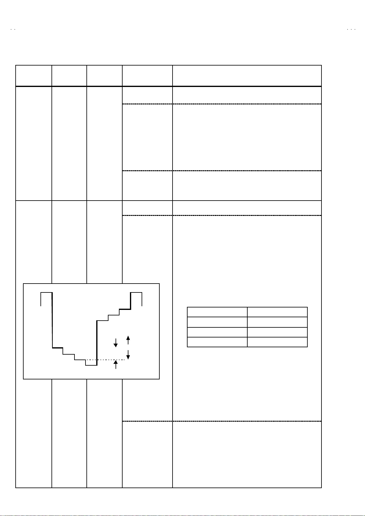
5. COLOUR [Method of adjust ment us i ng m ea suring i nstrument]
PAL COLOUR
1. I np ut a PAL f ul l fiel d c ol o ur b ar s ignal (75% whi t e) .
2. Select 2. V/C from SERVICE MENU.
3. Select 5. COLOUR with th e ME NU ▼/▲ key.
4. Set the initial setting value of PAL COLO UR with the MENU
- or + key.
5. Connect the oscilloscope between TP -47G and TP-E (#).
6. Adju s t PA L CO LOU R to br in g t he v alue of (A) in th e illustration
B
R
M
to the values as shown given billow.
(Voltage diff erenc e between (W) and (G))
(-)
Model
0V
(A)
(+)
G
AV-2134EE
AV-2124EE
AV-2104EE
/SK
/SK
/SK
Voltage(W-G)
+12V
+12V
+9V
SECAM COLOUR
NTSC 3.58 COLOUR
1. Input a SECAM full field colour bar signal (75% white).
2 . Set the ini tia l s etting value of S ECAM COLOUR wi th the MENU
- or + key.
3. Adjust SECAM COLOUR to bring the value of
(A)
in the
illustra tion to t he val ue s as s ho wn g iv en billow.
Voltag e d if ference betw een ( W) and (G))
Model Voltage(W-G)
AV-2134EE
AV-2124EE
AV-2104EE
/SK
/SK
/SK
+8V
+8V
+6V
1. I np ut a NTS C 3. 58 ful l fi e ld c ol o ur b ar s ignal (75% whi t e) .
2. Se t the i nit ia l setting val ue of NT SC 3. 58 COLO UR with th e
MEN U - or + key.
3. Ad just NTSC 3. 58 COLOUR to bring the value of (A) in the
illustra tion to t he val ue s as s ho wn g iv en billow.
(Voltage diff erenc e between (W) and (G))
Model Voltage (W-G)
AV-2134EE
AV-2124EE
AV-2104EE
/SK
/SK
/SK
+11V
+11V
+8V
NTSC 4.43 COLOUR
When NTSC 3.58 is set, NTSC 4.43 will be aut omatically set at the
r espec ti v e val ues .
No. 51959
25
Page 26
A
V-2134EE
A
A
y
g
(B)
V-2124EE
V-2104EE
Item
Ad justment
of TINTⅠⅠⅠⅠ
Ad justment
of TINTⅡⅡⅡⅡ
Measuring
instrument
Signa l
gener ator
Remote
control unit
Signa l
gener ator
Oscilloscope
Remote
control unit
Test point A djustment part Desc r i pti on
6. TINT [Method of adjustment without measuring ins trum ent ]
TP-47G/R
TP-E (####)
[CRT
SOCKET
PWB]
NTSC 3.58 TINT
NTSC 4.43 TINT
6. TINT [Method of adjustment us ing measu ring inst r um ent]
NTSC 3.58 TINT
1. Input a NTSC 3.58 full field colour bar signal (75% white).
2. Select 2. V/C from SERVICE MENU.
3. Select 6. TI N T with the MENU ▼/▲ key.
4. Set t he i ni t ial s etting v al u e of NT SC 3.58 wi th t h e M EN U - or +
key.
5. If you cannot get the best tint with the initial setting value, make
f i ne adju st m ent until you get the best tint.
When NTSC 3.58 is set, NTSC 4.43 will be aut omatically set at the
r espec ti v e val ues .
1. I np ut a NTS C 3.5 8 f ul l fi el d c ol o ur b ar s i gna l (75% w hi te) .
2. Select 2. V/C from SERVICE MENU.
3. Select 6. TI N T with the MENU ▼/▲ key.
4. Set t he i ni t ial s etting v al u e of NT SC 3.58 wi th t h e M EN U - or +
key.
5. Connect the oscilloscope between TP -47G/R and TP-E. (#).
6. Adjust NTSC 3.58 TINT to bring the value of (B) in the
illustra tion to t he val ue s as s ho wn g iv en billow.
(Voltage diff erenc e between (W) and (Cy))
W
B
R
M
(-)
0V
Y
C
G
(+)
NTSC 4.43 TINT
When NTSC 3.58 is set, NTSC 4.43 will be aut omatically set at the
r espec ti v e val ues .
Model Vol tage(W- Cy)
AV-2134EE
AV-2124EE
AV-2104EE
/SK
/SK
/SK
+9V
+9V
+7V
26
No. 51959
Page 27

A
V-2134EE
A
A
V-2124EE
V-2104EE
Item
of SECAM
BL ACK
OFFSET
KEY ASSIGNMENT OF REMO T E CONTROL UNIT
COLOUR
ON
COLOUR
OFF
Measuring
instrument
Remote
control unit
Signa l
gener ator
12 3
Test point Adjus tment part Descr iption
7.SECAM
BL ADJUST
[Method of adjustment us i ng m ea suring i nstrumen t]Ad justment
1. Input a SECAM full field colour bar signal.
2. Select 2. V/C from SERVICE MENU.
3. Select 7. SECAM BL ADJUST with ▼/▲MENU key.
4 . Set the ini tia l s etting value with the – or + MENU key.
5. Switch the ①key (c ol our O FF ) a nd ②key (col our O N ) on th e
remote co ntrol an d make sur e that th ere is no colour on th e
black and white screen.
6. I f the bl ac k and w hi te sc r e en i s n ot bes t w i th t he init i al s ett ing
value, make f ine adj ustm ent unt il you get the b est black an d
w hit e sc r een .
7. W hile watchin g the scr een, adjus t the value t o be the same
col o ur bet w een ON & O FF b y T en k ey on th e r em ote c ontr ol
unit.
8. Press the DISPLAY key twice to return to the norm al screen.
4
7
56
8
9
No. 51959
27
Page 28

A
V-2134EE
A
A
V-2124EE
V-2104EE
DEFL ECTI ON CIRCUIT ADJ USTME NT
"
There are 2 modes of adjustment (s etting value) ------ ① 50Hz mode and ② 60Hz mode ----- depending upon the kind of signals
(vertical frequency 50Hz / 60Hz).
"
When adjusted in mode ① , mode ② will be au to matically set .
The s etting ( adjustment) usi ng the REMOTE CO NTROL UNI T i s ma de on the basis of the initia l set ti ng values.
The s etting values which adjust the screen to t he optimum condition can be different fro m the ini ti al setting values.
Item
Ad justment
of V.HEIGHT
&
V.POSITION
Screen
size
92%
Measuring
instrument
Test point A djustment part Desc r i pti on
Signa l
gener ator
Remote
control unit
DEF
1. VER. POSITION
50Hz
: SELECT
/
- / + : OPERATE DI SP : EXIT
Screen size
1. VER.
POSITION
3. VE R. HE IG HT
PAL
***
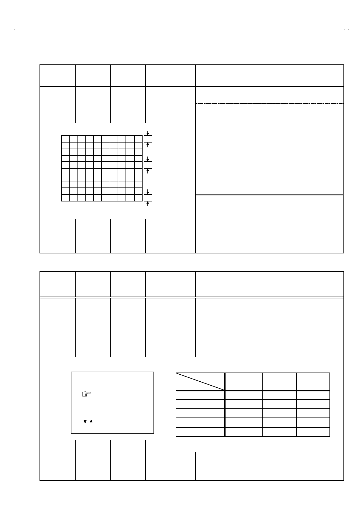
1. Input a c i rcl e pattern sig nal.
2. Select 3. DE F . from SERVICE MENU.
3. Select 1. VER. POSITION with the MENU ▼/▲ key.
4. Set the initial setting value 1. VER. POSITI ON with the MENU
-/ + key.
5. Adjust V and V’ to be e qual with the MENU - / + key as show n in
Fig.2.
6. Input a cross-hatch signal.
7. Select 3. V. HEIGHT with th e ME NU ▼/▲ key.
8. Set the initial setting value 3. V. H EIGHT with the MENU - / +
key.
9. As s h own i n Fig .1, adj u st VE R. HEIGHT and m ake t he ve r tic al
screen size 92% of the picture size with the MENU - / + keys of
re mote co ntrol unit.
Picture
size
100%
Ad justment
of
HOR.
POSITION
28
Picture size 100%
Fig.1
Signa l
2. HOR. POSIT ION 10. Input a circle pattern signal.
gener ator
Remote
control unit
HH"
V
V'
Fig.2
No. 51959
11. Sele ct 2. HOR POSITION wit h the MENU ▼/▲ key.
12. Set the initial setting value of 2. HOR. POSITION with the
MEN U - / + key.
13. Adju st 2. HOR. POSITION to m ake H=H" as shown in Fig. 2
with the MENU - / + key.
Page 29
A
V-2134EE
A
A
V-2124EE
V-2104EE
Item
Ad justment
of VER. LI N.
& VER.
SCURVE
Measuring
instrument
Signa l
gener ator
Remote
control unit
Fig.3
Test point Adjustment pa r t Descri ption
4. VER. LIN.
5. VER. S C URV E
TOP
CENTER
BOTTOM
●●●● When the vertical linearity has been deteriorated
remarkably, perform the following s teps.
14. Input a cross-hatch signal.
15. Select 4. VER. LIN. with the MENU ▼/▲ key.
16. Set the initial setting value of 4. VER LIN. with the MENU - / +
key.
17. Select 5. VER. SCURVE with the MENU ▼/▲ key.
18. Set the initial setting value of 5. V ER. SCURVE with the
MEN U - / + key.
19. Adjust 4. V ER . LIN. and 5. VER. SC URV E so that the spac es
of each line as shown in Fig. 3 on TOP, CENTER and
BOTTOM become uniform.
.
M ake s u r e that th e adj us t me nt i s pr o per l y do ne on t he sc r e en of
60 H z mode .
[NOTE]
"
Adjust to make both 50Hz & 60Hz are the same v. size and
fine s traigh t line.
"
When adjust again, adjust 50Hz mode first.
"
When adju s t i n 6 0Hz mode, on ly 60Hz mo de is adjus t.
VSM PRESET SETTING
Item
Set ti ng of
VSM
PRESET
Measuring
instrument
Remote
control unit
TINT
COLOUR
BRIG HT
CONT.
SHARP
/ :SELECT
- / + : OPERATE DISP : EXIT
Test point Adjustment pa r t Descri ption
BRIG HT
TINT
COLOUR
BRIG HT
CONT.
SHARP
••••
VSM PRESET
VSM
**
**
**
**
**
Setting Item
1. Select 4. VSM PRESET from the SERV ICE MENU.
2. Select BRIGHT with the PICTURE MODE key.
3. Adju s t t h e ME N U ▼/▲ an d M EN U - or + k ey to br i ng t h e s et
val ues of TI NT
table.
4. R especti vely se lect th e VSM PRESET mode for SOFT an d
ST ANDARD, and m ake similar adjustment as in 3 ab ove.
TINT +15
COLOUR +15
BRIGHT +15
CONT +30 + 15 +11
SHARP +15
~~~~
SHARP to the values shown in the below
BRIGHT STANDARD SOFT
←
←
←←
←←
←
+12
No. 51959
29
Page 30
A
V-2134EE
A
A
V-2124EE
V-2104EE
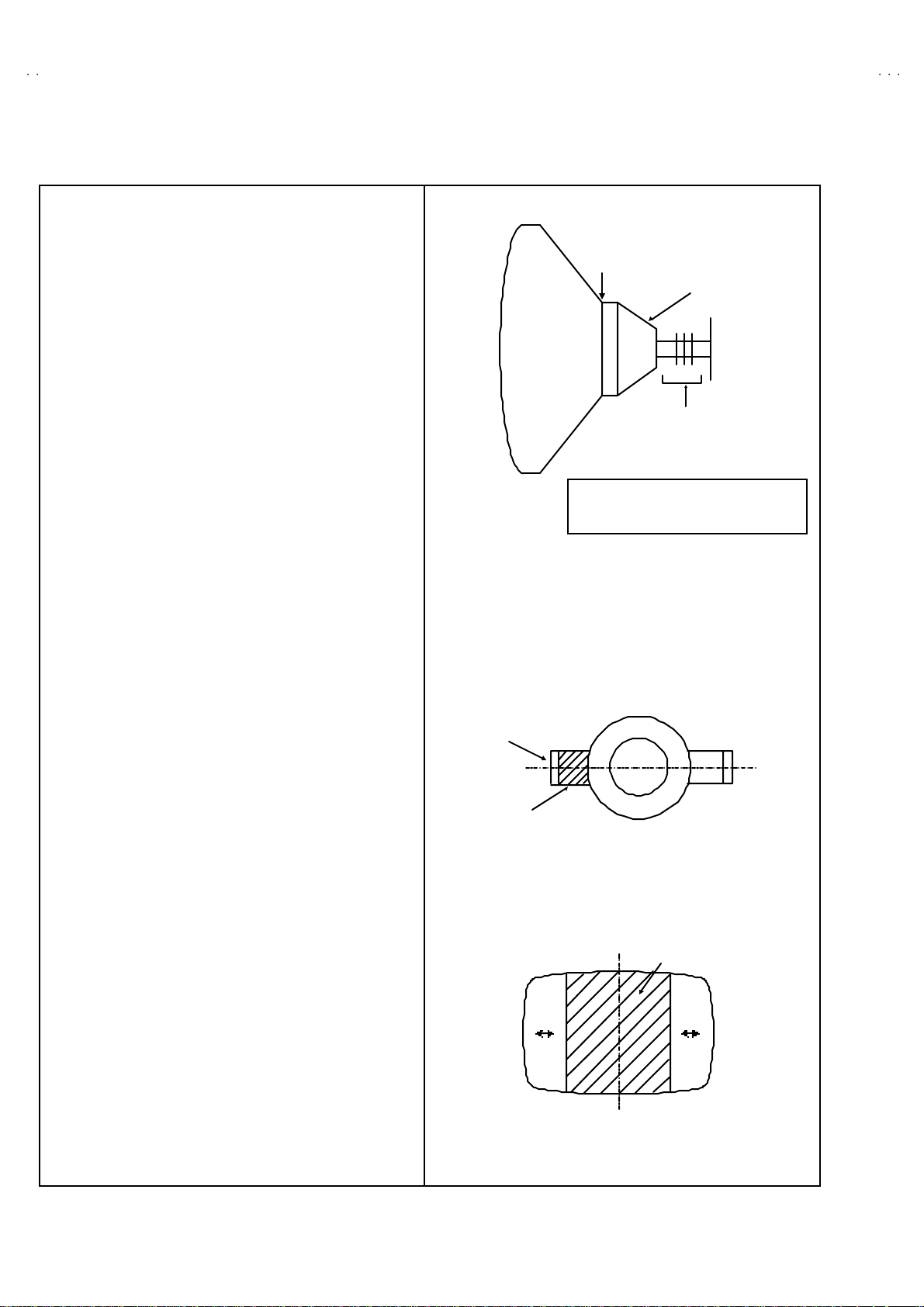
PURITY / CO NVERGENCE ADJUSTMENT
PURITY ADJUS TMENT
1. Demagnetize CRT with the demagnetizer.
2. Loosen the retainer screw of the deflec tion yoke.
3. Remove the wedges.
4. Inp ut a gr een ras t er si gn al fr om the si gn al ge ner ator , an d tur n
the screen to green raster.
5. Mov e the def l ection yoke backward.
6. Br ing t he l o ng l ug of th e pur i t y m agn et s on the s ho rt lu g a nd
position them horizontally. (Fig. 2)
7. Adjust t he gap between t wo lugs so that the G REEN RAS TER
will com e in to the cente r of the sc reen. (Fig.3)
8. M ove the d eflect ion yoke for ward, a nd fix th e position of th e
def lect ion yoke s o t ha t the whole s c reen will b ecome green.
9. Insert the wedge to the top side of the deflection yoke so that it
will not move.
CRT
WEDGE
DEFLECTION
YOKE
P
46
P / C
MAGNETS
#
P/C MAGNETS
P : PURITY MAGNET
4 : 4 POLES ( c on v er gen ce m agnets)
6 : 6 POLES ( conv er gen c e m agn ets )
Fig.1
PURITY MAGNETS
10 . I np ut a cros s hat c h si gnal.
11 . Veri fy tha t th e scr een is hori z on tal .
12 . I np ut r ed and bl ue r as ter s i gn al s, a nd m ake su r e t ha t pur i t y i s
properly adjusted.
Long lug
Sh ort lug
(FRONT VIEW)
Bring the long lug over the short lug
and position them horizontally.
Fig.2
GREEN RASTER
CENTER
Fig.3
30
No. 51959
Page 31

A
A
A
STATIC CONVERGENCE ADJUSTMENT
1. Input a cross hatch signal.
2. Us in g 4 - po le c on v er ge nce m agn ets , ov e rlap t he r e d and blue
lines in the center of the screen (Fig. 1) and turn them to
magenta (red/blue).
3. Using 6-pole convergence magnets, overlap the
m ag enta( re d/ b l ue) a nd g r een li nes i n the cen t er of t he sc r een
and turn them to white.
4. Repeat 2 and 3 above, and make best convergence.
DYNAMIC CONVERGENCE ADJUSTMENT
1. Mov e the def lec ti on yoke up and d ow n and o v er l ap th e li n es in
the periphery. (Fig. 2)
2. Move the deflection yoke left to right and overlap the lines in the
p eri p her y. (Fi g. 3)
3. Repeat 1 and 2 above, and make best convergence.
(FRONT VIEW)
(FRONT VIEW)
BLUE
GREEN
RED
Fig.1
GREEN
V-2134EE
V-2124EE
V-2104EE
BLUERED
RED
GREEN
BLUE
●
After adjustment, fix the wedge at the original position.
Fasten the retainer screw of the deflection yoke.
Fi x the 6 m agnets with glue.
(FRONT VIEW)
GREEN
RED
BLUE
GREEN REDBLUE
Fig.2
Fig.3
BLUE
GREEN
RED
RED
GREEN
BLUE
BLUE
GREEN
RED
No. 51959
31
Page 32

A
V-2134EE
A
A
V-2124EE
V-2104EE
REPLACEMENT OF CHI P COMPONENT
!
CAUTIONS
1. Avoid he ating for more than 3 se conds.
2. Do not rub the elect rodes and t he resist parts of the patt ern.
3. When removing a chip part, melt the solder adequately.
4. Do not reuse a chip part after removing it.
! SOLDERING IRON
1. Use a high insulation soldering iron with a t hin pointed end of it.
2. A 30w soldering iron is rec ommended for easily removing parts.
!
RE PLACE MENT STEPS
1. How to remove Chip parts
$$$$
Resistors, capacitors, etc
(1) As shown in the figure, push the part with tweezers and
al te rn atel y m el t th e sol de r at eac h end.
(2) Shift with tweezers and remove the chip part.
$
$ Transistors, diodes, variable r esistors, etc
$$
(1) Apply extra solder to each lead.
2. How to install Chip parts
$$$$
Resistors, capacitors, etc
(1) Apply solder to the pattern as indicated in the figure.
( 2) Gr as p the c h i p p art with t w ee zer s and pl ac e i t on t h e s older.
Then heat and melt the solder at both ends of the chip part.
$
$ Transistors, diodes , variable resistors, etc
$$
(1) Apply solder to the pattern as indicated in the figure.
(2) Grasp the chip part with tweezers and place it on the solder.
(3 ) First so lder lead A as indicated in the figure.
SOLDE R SOLDE R
(2) As shown in the figure, push the part with tweezers and
al te rn atel y m el t t h e sol der at each le ad. S hi ft an d r em ov e the
chip part.
(4) Then solder leads B and C.
Note : After removing the part, remove remaining solder from the
pattern.
32
No.51959
A
B
C
A
B
C
 Loading...