

Page 1
SERVICE MANUAL
COLOUR TELEVISION
YA08020052
AV-20RM4SE,
AV-21RM4SE,
AV-21RM4SN,
AV-21RM4SP
RM-C1100 TV
[AV-21RM4]
TABLE OF CONTENTS
1 PRECAUTION. . . . . . . . . . . . . . . . . . . . . . . . . . . . . . . . . . . . . . . . . . . . . . . . . . . . . . . . . . . . . . . . . . . . . . . . . 1-3
2 SPECIFIC SERVICE INSTRUCTIONS . . . . . . . . . . . . . . . . . . . . . . . . . . . . . . . . . . . . . . . . . . . . . . . . . . . . . . 1-5
3 DISASSEMBLY . . . . . . . . . . . . . . . . . . . . . . . . . . . . . . . . . . . . . . . . . . . . . . . . . . . . . . . . . . . . . . . . . . . . . . . 1-6
4 ADJUSTMENT . . . . . . . . . . . . . . . . . . . . . . . . . . . . . . . . . . . . . . . . . . . . . . . . . . . . . . . . . . . . . . . . . . . . . . . 1-11
5 TROUBLESHOOTING . . . . . . . . . . . . . . . . . . . . . . . . . . . . . . . . . . . . . . . . . . . . . . . . . . . . . . . . . . . . . . . . . 1-19
COPYRIGHT © 2005 Victor Company of Japan, Limited
No.YA080
2005/2
Page 2
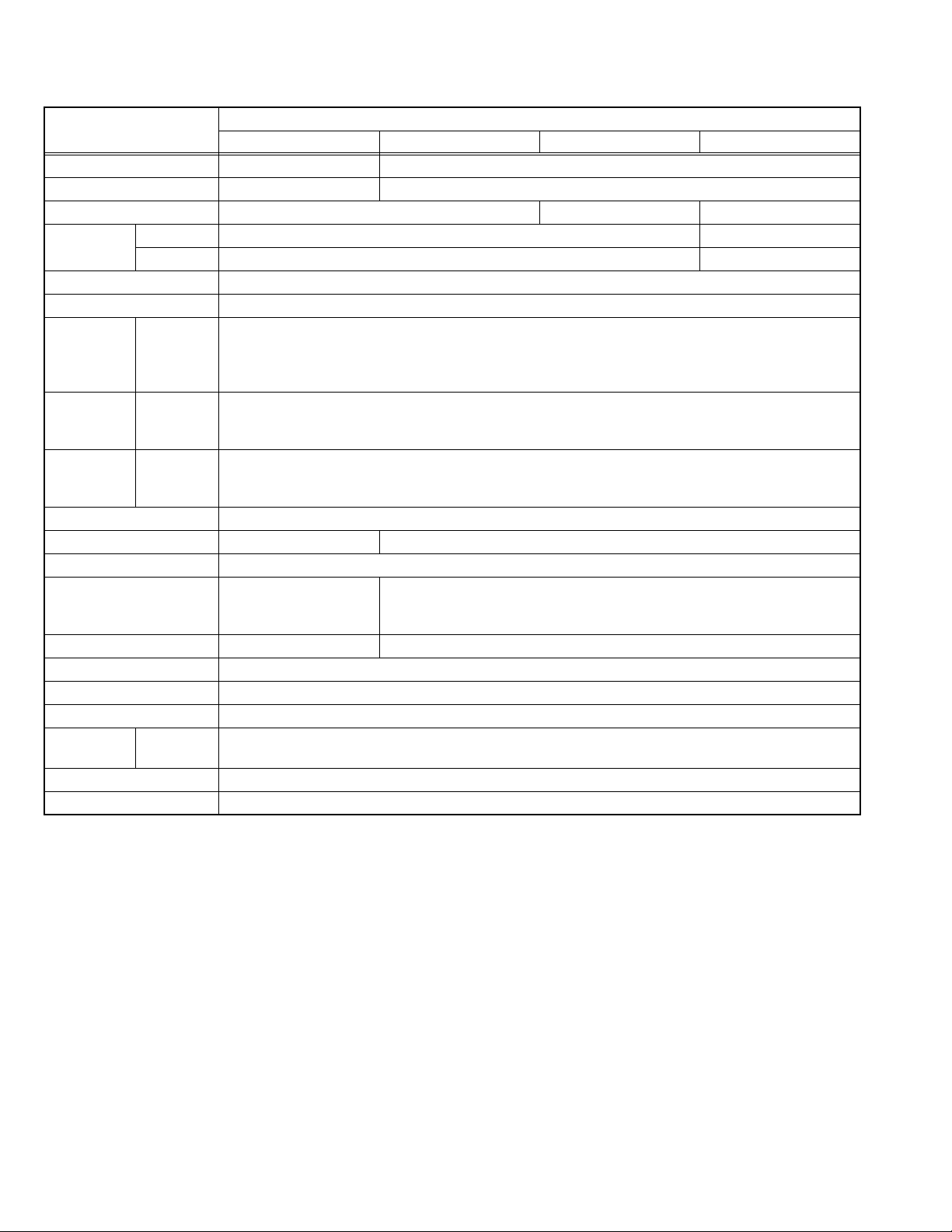
SPECIFICATION
Item
Dimensions ( W × H × D )
Mass 18kg 21kg
TV RF System B/G, L B/G, D/K B/G
Colour System
Sound System A2 / NICAM
Teletext System TOP / WST
Receiving
Frequency
Intermediate
Frequency
Colour Sub
Carrier
Frequency
Power Input AC220V - AC240V, 50Hz
Power Consumption
Aerial Input Terminal 75Ω unbalanced, coaxial
Picture Tube Size Visible size : 48cm (20"),
High Voltage
Speaker 5.7cm × 12.6cm, Oval type × 2
Audio Output 5.5W (10%THD)
EXT-1 Input / Output 21-pin Euro connector (SCRAT socket) × 1
EXT-2 Input Video
Headphone Jack Mono mini jack 3.5mm × 1
Remote Control Unit VE-30017763 (RM-C1100), (AA/R06 dry battery × 2)
Design & specifications are subject to change without notice.
TV Mode PAL / SECAM PAL
Video Mode PAL / SECAM / NTSC 3.58 / NTSC 4.43
VHF(VL)
VHF(VH)
UHF
CATV
VIF
SIF
PAL
SECAM
NTSC
Audio(L/R)
AV-20RM4SE AV-21RM4SE AV-21RM4SP AV-21RM4SN
60.6cm × 47.5cm × 49.0cm
46.25MHz - 168.25MHz
175.25MHz - 463.25MHz
471.25MHz - 863.25MHz
S01 - S41 / S75 - S79 (B/G), S01 - S20 / S75 - S77(L)
38.9MHz
33.4MHz (5.5MHz:B/G)
32.4MHz (6.5MHz:L)
4.43MHz
4.40625MHz / 4.25MHz
3.58MHz / 4.43MHz
85W (Max) / 4W (Standby)
Measured diagonally
(H:41.2cm × V:31.2cm)
26kV (in cut-off service mode)
1V(p-p) 75Ω, RCA pin jack × 1
500mV(rms) (-4dBs), High Impedance, RCA pin jack × 2
60.6cm × 47.5cm × 47.0cm
85W (Max) / 3W (Standby)
Visible size : 51cm (21"), Measured diagonally
(H:41.6cm × V:31.5cm)
28kV (in cut-off service mode)
Content
PAL / NTSC 3.58 / NTSC 4.43
1-2 (No.YA080)
Page 3

SECTION 1
PRECAUTION
1.1 SAFETY PRECAUTIONS [EXCEPT FOR UK]
(1) The design of this product contains special hardware,
many circuits and components specially for safety
purposes. For continued protection, no changes should be
made to the original design unless authorized in writing by
the manufacturer. Replacement parts must be identical to
those used in the original circuits. Service should be
performed by qualified personnel only.
(2) Alterations of the design or circuitry of the products should
not be made. Any design alterations or additions will void
the manufacturer's warranty and will further relieve the
manufacturer of responsibility for personal injury or
property damage resulting therefrom.
(3) Many electrical and mechanical parts in the products have
special safety-related characteristics. These
characteristics are often not evident from visual inspection
nor can the protection afforded by them necessarily be
obtained by using replacement components rated for
higher voltage, wattage, etc. Replacement parts which
have these special safety characteristics are identified in
the parts list of Service manual. Electrical components
having such features are identified by shading on the
schematics and by ( ) on the parts list in Service
manual. The use of a substitute replacement which does
not have the same safety characteristics as the
recommended replacement part shown in the parts list of
Service manual may cause shock, fire, or other hazards.
(4) Don't short between the LIVE side ground and
ISOLATED (NEUTRAL) side ground or EARTH side
ground when repairing.
Some model's power circuit is partly different in the GND.
The difference of the GND is shown by the LIVE : ( ) side
GND, the ISOLATED (NEUTRAL) : ( ) side GND and
EARTH : ( ) side GND.
Don't short between the LIVE side GND and ISOLATED
(NEUTRAL) side GND or EARTH side GND and never
measure the LIVE side GND and ISOLATED (NEUTRAL)
side GND or EARTH side GND at the same time with a
measuring apparatus (oscilloscope etc.). If above note will
not be kept, a fuse or any parts will be broken.
(5) If any repair has been made to the chassis, it is
recommended that the B1 setting should be checked or
adjusted (See B1 POWER SUPPLY check).
(6) The high voltage applied to the picture tube must conform
with that specified in Service manual. Excessive high
voltage can cause an increase in X-Ray emission, arcing
and possible component damage, therefore operation
under excessive high voltage conditions should be kept to
a minimum, or should be prevented. If severe arcing
occurs, remove the AC power immediately and determine
the cause by visual inspection (incorrect installation,
cracked or melted high voltage harness, poor soldering,
etc.). To maintain the proper minimum level of soft X-Ray
emission, components in the high voltage circuitry
including the picture tube must be the exact replacements
or alternatives approved by the manufacturer of the
complete product.
(7) Do not check high voltage by drawing an arc. Use a high
voltage meter or a high voltage probe with a VTVM.
Discharge the picture tube before attempting meter
connection, by connecting a clip lead to the ground frame
and connecting the other end of the lead through a 10kΩ
2W resistor to the anode button.
(8) When service is required, observe the original lead dress.
Extra precaution should be given to assure correct lead
dress in the high voltage circuit area. Where a short circuit
has occurred, those components that indicate evidence of
overheating should be replaced. Always use the
manufacturer's replacement components.
(9) Isolation Check (Safety for Electrical Shock Hazard)
After re-assembling the product, always perform an
isolation check on the exposed metal parts of the cabinet
(antenna terminals, video/audio input and output terminals,
Control knobs, metal cabinet, screw heads, earphone jack,
control shafts, etc.) to be sure the product is safe to operate
without danger of electrical shock.
a) Dielectric Strength Test
The isolation between the AC primary circuit and all metal
parts exposed to the user, particularly any exposed metal
part having a return path to the chassis should withstand a
voltage of 3000V AC (r.m.s.) for a period of one second. (.
. . . Withstand a voltage of 1100V AC (r.m.s.) to an
appliance rated up to 120V, and 3000V AC (r.m.s.) to an
appliance rated 200V or more, for a period of one second.)
This method of test requires a test equipment not generally
found in the service trade.
b) Leakage Current Check
Plug the AC line cord directly into the AC outlet (do not use
a line isolation transformer during this check.). Using a
"Leakage Current Tester", measure the leakage current
from each exposed metal part of the cabinet, particularly
any exposed metal part having a return path to the chassis,
to a known good earth ground (water pipe, etc.). Any
leakage current must not exceed 0.5mA AC (r.m.s.).
However, in tropical area, this must not exceed 0.2mA AC
(r.m.s.).
Alternate Check Method
Plug the AC line cord directly into the AC outlet (do not
use a line isolation transformer during this check.). Use
an AC voltmeter having 1000Ω per volt or more
sensitivity in the following manner. Connect a 1500Ω
10W resistor paralleled by a 0.15µF AC-type capacitor
between an exposed metal part and a known good earth
ground (water pipe, etc.). Measure the AC voltage
across the resistor with the AC voltmeter. Move the
resistor connection to each exposed metal part,
particularly any exposed metal part having a return path
to the chassis, and measure the AC voltage across the
resistor. Now, reverse the plug in the AC outlet and
repeat each measurement. Any voltage measured must
not exceed 0.75V AC (r.m.s.). This corresponds to
0.5mA AC (r.m.s.).
However, in tropical area, this must not exceed 0.3V AC
(r.m.s.). This corresponds to 0.2mA AC (r.m.s.).
AC VOLTMETER
(HAVING 1000 /V,
OR MORE SENSITIVITY)
0.15 F AC-TYPE
PLACE THIS PROBE
1500 10W
GOOD EARTH GROUND
ON EACH EXPOSED
ME TAL PAR T
(No.YA080)1-3
Page 4

1.2 SAFETY PRECAUTIONS [FOR UK]
(1) The design of this product contains special hardware and many circuits and components specially for safety purposes. For
continued protection, no changes should be made to the original design unless authorized in writing by the manufacturer.
Replacement parts must be identical to those used in the original circuits. Service should be performed by qualified personnel
only.
(2) Alterations of the design or circuitry of the product should not be made. Any design alterations or additions will void the
manufacturer's warranty and will further relieve the manufacturer of responsibility for personal injury or property damage
resulting therefrom.
(3) Many electrical and mechanical parts in the product have special safety-related characteristics. These characteristics are often
not evident from visual inspection nor can the protection afforded by them necessary be obtained by using replacement
components rated for higher voltage, wattage, etc. Replacement parts which have these special safety characteristics are
identified in the Parts List of Service Manual. Electrical components having such features are identified by shading on the
schematics and by ( ) on the Parts List in the Service Manual. The use of a substitute replacement which does not have the
same safety characteristics as the recommended replacement part shown in the Parts List of Service Manual may cause shock,
fire, or other hazards.
(4) The leads in the products are routed and dressed with ties, clamps, tubing’s, barriers and the like to be separated from live parts,
high temperature parts, moving parts and / or sharp edges for the prevention of electric shock and fire hazard. When service is
required, the original lead routing and dress should be observed, and it should be confirmed that they have been returned to
normal, after re-assembling.
WARNING
(1) The equipment has been designed and manufactured to meet international safety standards.
(2) It is the legal responsibility of the repairer to ensure that these safety standards are maintained.
(3) Repairs must be made in accordance with the relevant safety standards.
(4) It is essential that safety critical components are replaced by approved parts.
(5) If mains voltage selector is provided, check setting for local voltage.
1-4 (No.YA080)
Page 5
SECTION 2
SPECIFIC SERVICE INSTRUCTIONS
2.1 FEATURES
• It is a remote controlled color television.
• It can tune cable channels.
• Controlling the TV is very easy by its menu driven system.
• It has 1 Euroconnector sockets for external device.
• Front AV Input available.
• Simple teletext (Toptext, WST) system.
• It is possible to connect headphone.
• Direct channel access.
2.2 MAIN DIFFERENCE LIST
Item AV-20RM4SE AV-21RM4SE AV-21RM4SN AV-21RM4SP
MAIN PWB ASSY VE-20161051 VE-20161048 VE-20161045 VE-20161041
TV RF System B/G,D/K ← B/G B/G, L
Colour System (TV mode) PAL, SECAM ← PAL PAL, SECAM
TV RF System B/G,D/K ← B/G B/G, L
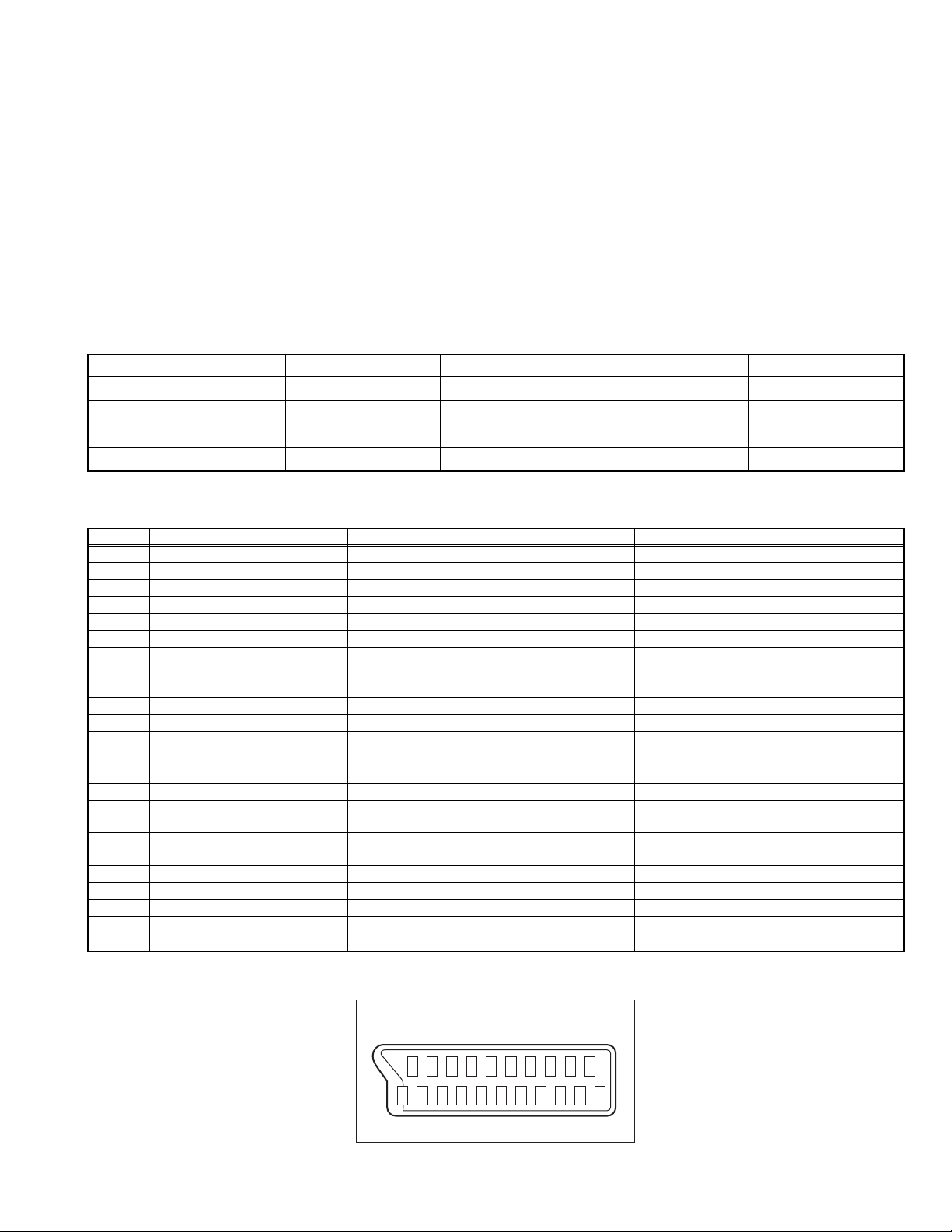
2.3 21-PIN EURO CONNECTOR (SCART) : EXT-1
Pin No. Signal designation Matching value EXT-1
1 AUDIO R output 500mV(rms) (Nominal), Low impedance Used (TV OUT)
2 AUDIO R input 500mV(rms) (Nominal), High impedance Used (R1)
3 AUDIO L output 500mV(rms) (Nominal), Low impedance Used (TV OUT)
4 AUDIO GND --- Used
5 GND (B) --- Used
6 AUDIO L input 500mV(rms) (Nominal), High impedance Used (L1)
7 B input 700mV
8 FUNCTION SW (SLOW SW) Low : 0V-3V
High : 8V-12V, High impedance
9 GND (G) --- Used
10 SCL / T-V LINK --- Not used
11 G input 700mV(B-W), 75 Ω Used
12 SDA3 --- Not used
13 GND (R) --- Used
14 GND (YS) --- Used
15 R / C input R : 700mV
C : 300mV
16 Ys input (FAST SW) Low : 0V-0.4V, 75 Ω
High : 1V-3V, 75 Ω
17 GND (VIDEO output) --- Used
18 GND (VIDEO input) --- Used
19 VIDEO output 1V
20 VIDEO / Y input 1V
21 COMMON GND --- Used
(P-P)
(P-P)
, 75 Ω Used
(B-W)
, 75 Ω
(B-W)
, 75 Ω
(P-P)
(Negative sync),75 Ω Used (TV OUT)
(Negative sync), 75 Ω Used
(P-P= Peak to Peak, B-W= Blanking to white peak)
• APS (Automatic Programming System).
• All programs can be named.
• Forward or backward automatic tuning.
• Sleep timer.
• Child Lock.
• Automatic sound mute when no transmission.
• 5 minutes after the broadcasting (closedown), the TV switches
itself automatically to stand-by mode.
Used
Used (R)
Used
Pin assignment
20 18 16 14 12 10 8 6 4 2
21 19 17 15 13 11 9 7 5 3 1
(No.YA080)1-5
Page 6

SECTION 3
DISASSEMBLY
3.1 DISASSEMBLY PROCEDURE
3.1.1 REMOVING THE REAR COVER
(1) Unplug the power cord.
(2) Remove the 6 screws [A].
(3) Withdraw the REAR COVER toward you.
3.1.2 REMOVING THE MAIN PWB
• Remove the REAR COVER.
(1) Slightly raise the both sides of the MAIN PWB by hand and
withdraw the MAIN PWB backward.
(If necessary, take off the wire clamp, connectors etc.)
3.1.3 REMOVING THE SPEAKER
• Remove the REAR COVER.
(1) Remove the 4 screws [B].
(2) Remove the speaker toward you.
3.1.4 REMOVING THE FRONT AV JACK PWB
• Remove the REAR COVER.
• Remove the MAIN PWB.
(1) Remove the 2 screws [C].
(2) Remove the FRONT AV JACK PWB.
3.1.6 CHECKING THE PW BOARD
• To check the back side of the PW Board.
(1) Pull out the PW Board. (Refer to REMOVING THE MAIN
PWB).
(2) Erect the PW Board vertically so that you can easily check
the back side of the PWB.
CAUTION:
• When erecting the PW Board, be careful so that there will be
no contacting with other PW Board.
• Before turning on power, make sure that the wire connector
is properly connected.
• When conducting a check with power supplied, be sure to
confirm that the CRT EARTH WIRE (BRAIDED ASS'Y) is
connected to the CRT SOCKET PWB.
3.1.7 WIRE CLAMPING AND CABLE TYING
(1) Be sure to clamp the wire.
(2) Never remove the cable tie used for tying the wires
together.
Should it be inadvertently removed, be sure to tie the wires
with a new cable tie.
3.1.5 REMOVING THE HEADPHONE JACK PWB
• Remove the REAR COVER.
• Remove the MAIN PWB.
(1) Remove the 1 screw [D].
(2) Remove the HEADPHONE JACK PWB.
1-6 (No.YA080)
Page 7
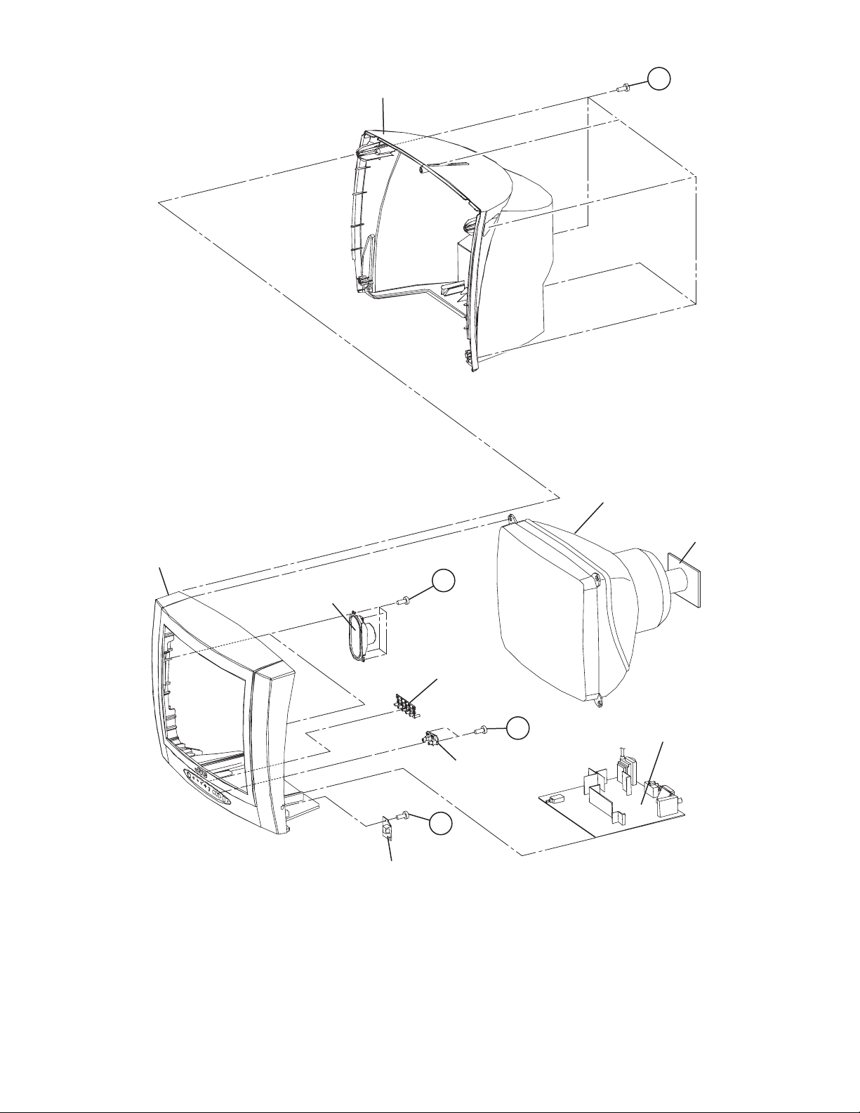
BACK COVER
A
(x6)
FRONT CABINET
SPEAKER
B
(x4)
FUNCTION
BUTTON
FRONT AV JACK PWB
D
(x1)
HEADPHONE JACK
PWB
PICTURE TUBE
CRT SOCKET PWB
(Within MAIN PWB)
C
(x2)
MAIN PWB
(No.YA080)1-7
Page 8
3.2 REPLACEMENT OF MEMORY IC
3.2.1 MEMORY IC
This model use a memory IC. This memory IC stores data for proper operation of the video and deflection circuits.
When replacing, be sure to use an IC containing this (initial value) data.
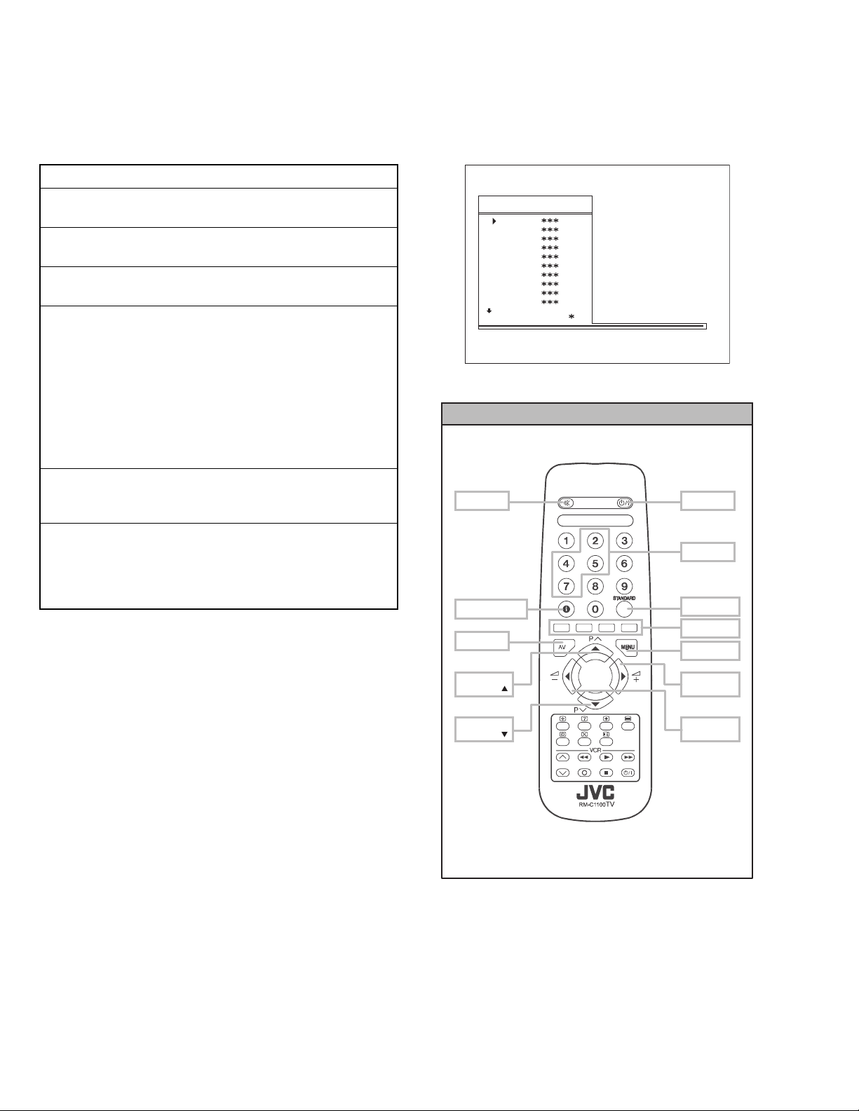
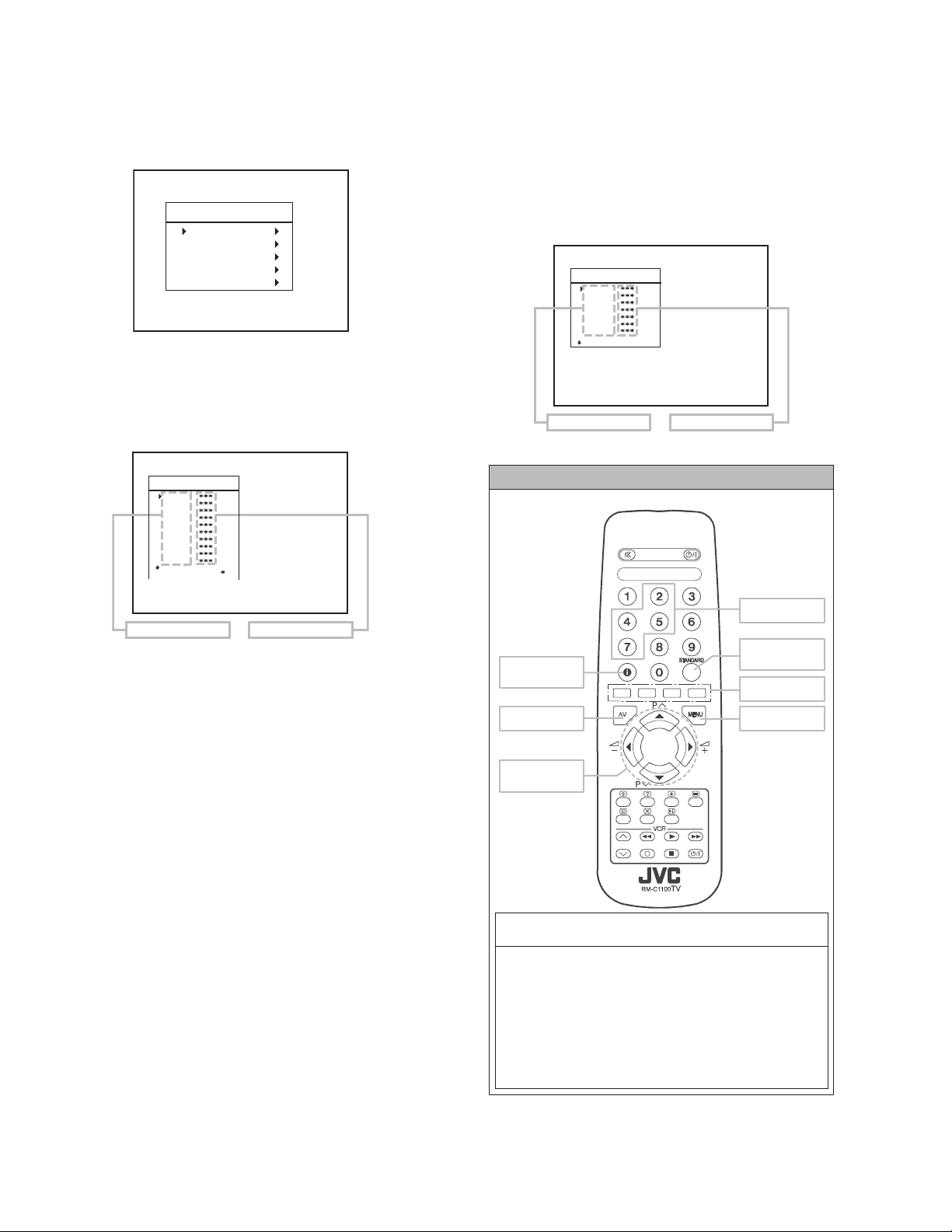
3.2.2 PROCEDURE FOR REPLACING MEMORY IC SERVICE MENU
PROCEDURE
1. Power off
Switch the power off and unplug the power cord from the outlet
2. Replace IC.
Be sure to use memory IC written with the initial data values.
3. Power on
Plug the power cord into the outlet and switch the power on.
4. SERVICE MENU setting
JVCAK30/37 B20
OSD
IF1
IF2
IF3
IF4
AGC
VLIN
RGBH
VSOF
VPOF
: 1 1 AVL
(1) Press [MENU] key and, while the displayed MENU screen,
press [4], [7], [2], [5] key on the remote control unit or press
[MUTING] key and [INFORMATION] key at the
simultaneously.
Fig.1
(2) The SERVICE MENU screen of Fig. 1 will be displayed.
(3) Verify what to set in the SERVICE MENU, and set
whatever is necessary (Fig.1). Refer to the SERVICE
SERVICE MENU SELECT KEY
ADJUSTMENT for setting.
(4) Press the [STANDARD] key to exit SERVICE MENU.
5. Receive channel setting
Refer to the OPERATING INSTRUCTIONS (USER'S GUIDE)
and set the receive channels (Channels Preset) as described.
MUTING
6. User settings
Check the user setting items according to after page.
Where these do not agree, refer to the OPERATING
INSTRUCTIONS (USER'S GUIDE) and set the items as
described.
INFORMATION
AV
POWER
NUMBER
STANDARD
COLOUR
MENU
1-8 (No.YA080)
ITEM
SELECT ( )
ITEM
SELECT ( )
Fig.2
VAL UE
SELECT (+)
VAL UE
SELECT (-)
Page 9
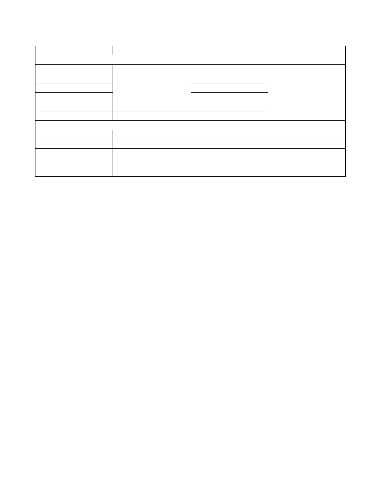
3.3 SETTING OF THE LAST MEMORY FOR SHIPMENT
3.3.1 USER SETTING VALUES
Setting item Setting value Setting item Setting value
PICTURE MENU INSTALL
BRIGHTNESS
CONTRAST BAND
COLOUR CHANNEL
SHARPNESS SEARCH
HUE(only NTSC) FINE TUNING
MODE AUTO STORE
SOUND MENU FEATURE MENU
BALANCE Center SLEEP TIMER OFF
BASS Center CHILD LOCK OFF
TREBLE Center LANGUAGE ENGLISH
MODE MONO AV-1 OUTPUT TV
EFFECT OFF
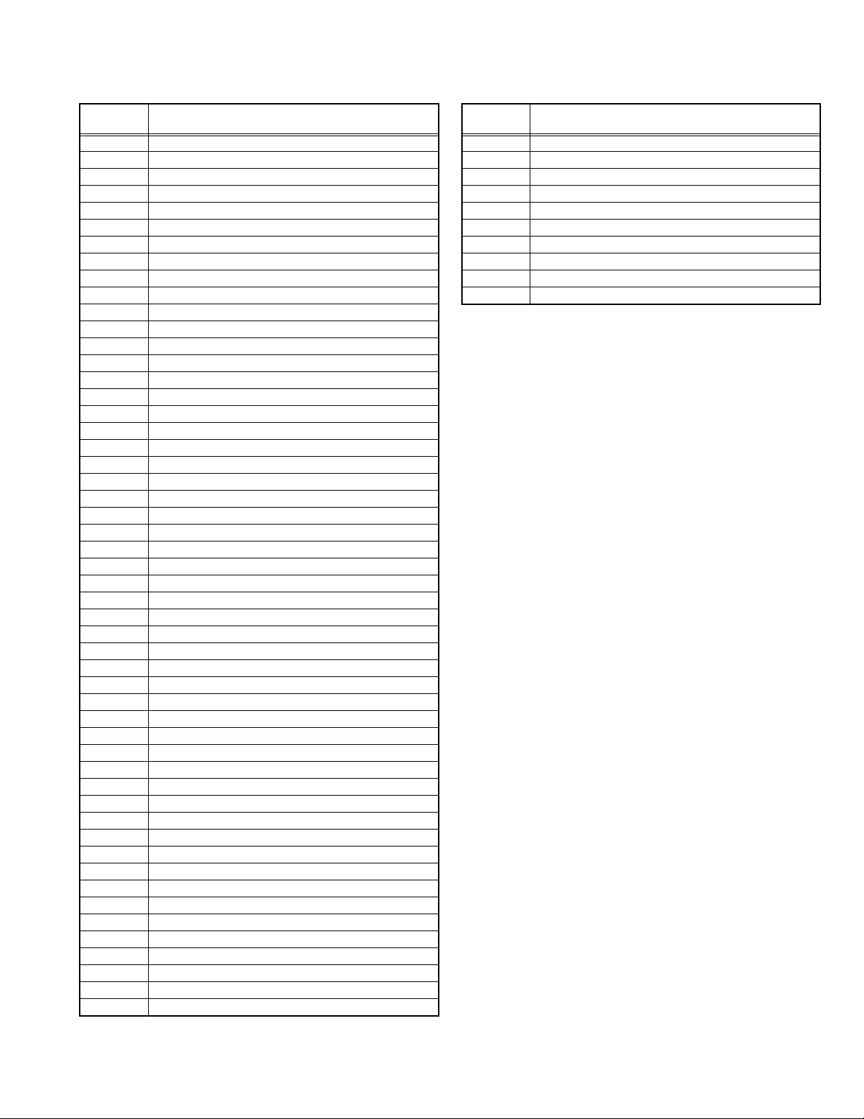
3.3.2 SETTING APS BIT IN SERVICE MENU
(1) Press the [INFORMATION] and [MUTING] keys enter service menu in TV mode simultaneously. Service Menu will appear.
(2) Press the []/[] key to select TX1(TELETEXT OPTION).
(3) Press the [7] key to set APS bit. (After this, bit 7 of TX1 will be "1")
(4) Press [STANDARD] key to exit service mode.
NOTE : DO NOT TURN OFF THE TV BY USING POWER BUTTON ON THE FRONT PANEL.
These adjust are automatically
restored when APS bit in
service menu is set.
The procedure for setting APS
bit is described below.
PROGRAMME
Refer to the INSTRUCTION
BOOK
(No.YA080)1-9
Page 10
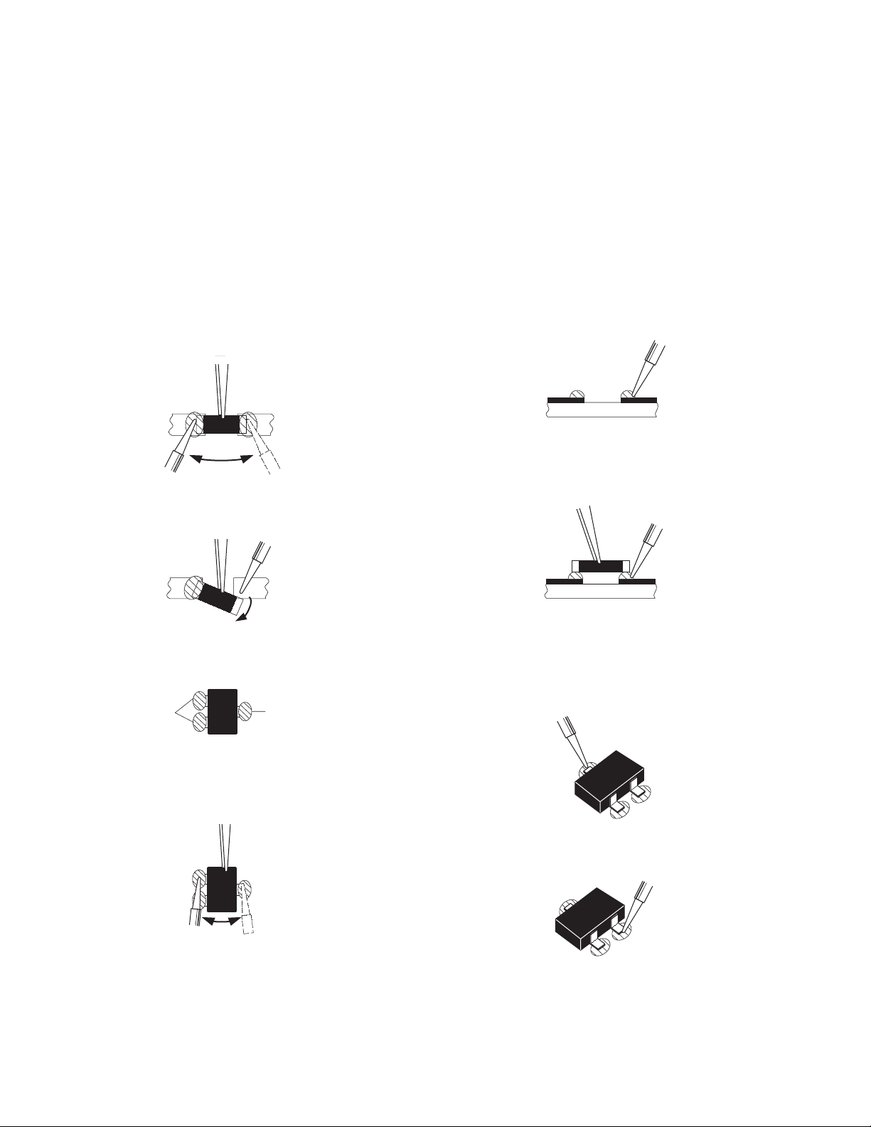
3.4 REPLACEMENT OF CHIP COMPONENT
3.4.1 CAUTIONS
(1) Avoid heating for more than 3 seconds.
(2) Do not rub the electrodes and the resist parts of the pattern.
(3) When removing a chip part, melt the solder adequately.
(4) Do not reuse a chip part after removing it.
3.4.2 SOLDERING IRON
(1) Use a high insulation soldering iron with a thin pointed end of it.
(2) A 30w soldering iron is recommended for easily removing parts.
3.4.3 REPLACEMENT STEPS
1. How to remove Chip parts
2. How to install Chip parts
[Resistors, capacitors, etc.]
(1) As shown in the figure, push the part with tweezers and
alternately melt the solder at each end.
(2) Shift with the tweezers and remove the chip part.
[Transistors, diodes, variable resistors, etc.]
(1) Apply extra solder to each lead.
SOLDER
SOLDER
[Resistors, capacitors, etc.]
(1) Apply solder to the pattern as indicated in the figure.
(2) Grasp the chip part with tweezers and place it on the
solder. Then heat and melt the solder at both ends of the
chip part.
[Transistors, diodes, variable resistors, etc.]
(1) Apply solder to the pattern as indicated in the figure.
(2) Grasp the chip part with tweezers and place it on the
solder.
(3) First solder lead A as indicated in the figure.
(2) As shown in the figure, push the part with tweezers and
alternately melt the solder at each lead. Shift and remove
the chip part.
NOTE :
After removing the part, remove remaining solder from the
pattern.
1-10 (No.YA080)
A
B
C
(4) Then solder leads B and C.
A
B
C
Page 11
SECTION 4
ADJUSTMENT
4.1 ADJUSTMENT PREPARATION
(1) You can make the necessary adjustments for this unit with
either the Remote Control Unit or with the adjustment tools
and parts as given below.
(2) Adjustment with the Remote Control Unit is made on the
basis of the initial setting values, however, the new setting
values which set the screen to its optimum condition may
differ from the initial settings.
(3) Make sure that AC power is turned on correctly.
(4) Turn on the power for set and test equipment before use,
and start the adjustment procedures after waiting at least
30 minutes.
(5) Unless otherwise specified, prepare the most suitable
reception or input signal for adjustment.
(6) Never touch any adjustment parts which are not specified
in the list for this adjustment - variable resistors,
transformers, condensers, etc.
(7) Presetting before adjustment.
Unless otherwise specified in the adjustment instructions,
preset the following functions with the remote control unit:
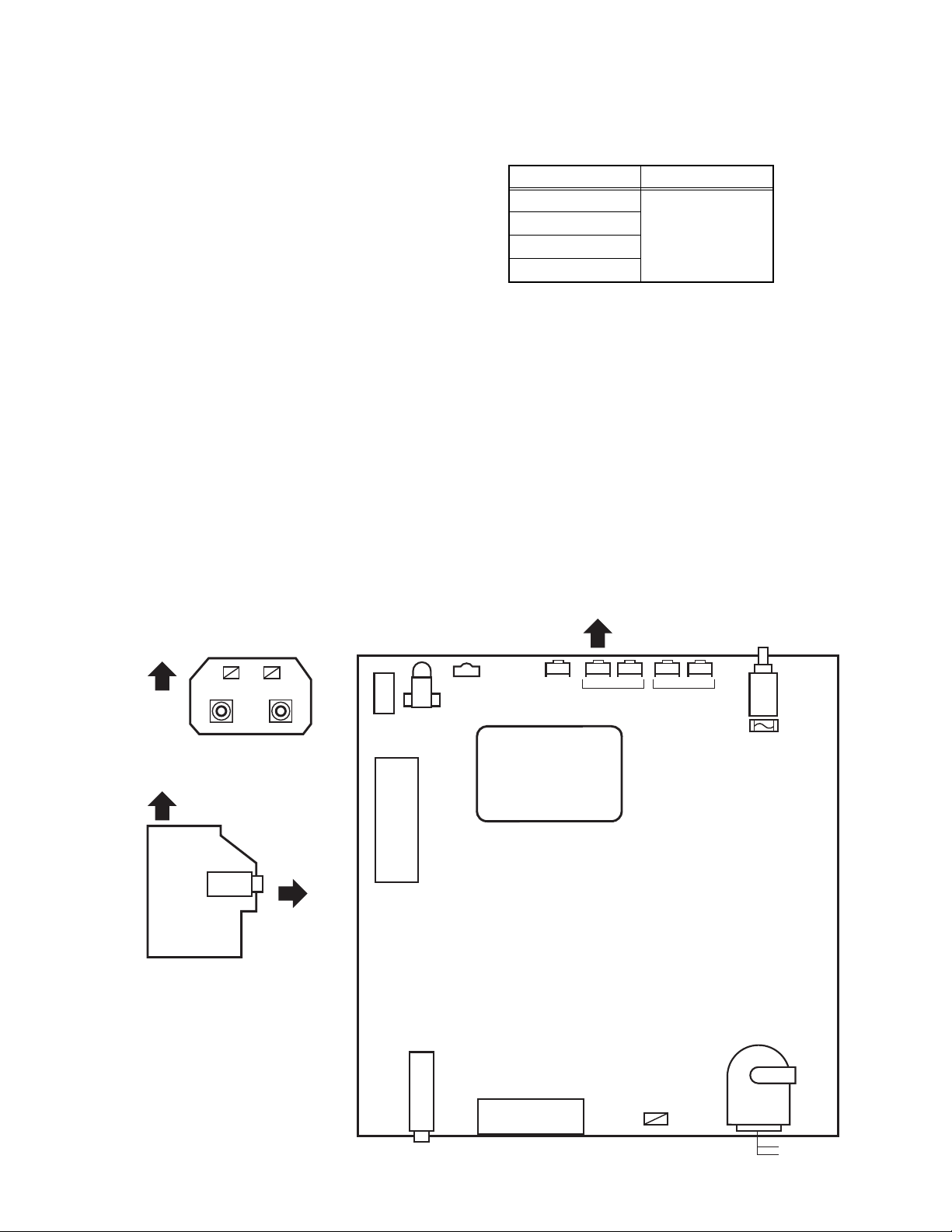
4.4 ADJUSTMENT LOCATIONS
Setting item Setting value
BRIGHTNESS
CONTRAST
COLOUR
Center
SHARPNESS
4.2 ADJUSTMENT EQUIPMENT
(1) DC voltmeter (or digital voltmeter)
(2) Signal generator (Pattern generator)
: [PAL / SECAM / NTSC]
(3) Remote control unit
4.3 ADJUSTMENT ITEM
• FOCUS ADJUSTMENT
• SCREEN ADJUSTMENT
• OSD HORIZONTAL POSITION ADJUSTMENT
• IF ADJUSTMENT
• AGC AUTOMATICALLY ADJUSTMENT
• DEFLECTION ADJUSTMENT
• WHITE BALANCE ADJUSTMENT
TOP
FRONT AV JACK PWB
TOP
HP
HEADPHONE JACK PWB
IC500
EEP ROM
IC501
MICOM
TUNER
LED
REMOCON
RECEIVER
MENU
AV-1(SCART)
FRONT
CH. / PROG.
PL602
(+) (-)(+) (-)
VOL.
MAIN
SW
FUSE
FBT
MAIN PWB
UPPER:FOCOUS
LOWER:SCREEN
(No.YA080)1-11
Page 12
4.5 BASIC OPERATION OF SERVICE MODE
4.5.1 HOW TO ENTER SERVICE MODE
(1) Press the MENU key.
(2) MENU screen will be displayed (fig.1).
MENU SCREEN
MENU
SOUND
PICTURE
FEATURE
INSTALL.
PROGRAM.
Fig.1
(3) While the MENU screen is displayed , press the [4], [7], [2],
[5] key or [INFORMATION] key and [MUTING] key
simultaneously.
(4) The SERVICE MENU screen will be displayed (fig.2).
SERVICE MENU
4.5.4 HOW TO ENTER THE GEOMETRY MENU
• This model is built-in GEOMETRY MENU for geometry
adjustment.
(1) Enter the SERVICE MODE.
(2) Press the [GREEN] key, geometry menu appears (Fig. 3).
(3) Press the []/[] key and select the adjustment item.
(4) Press the []/[] key and set the setting value.
GEOMETRY MENU
GEOMETRY
VSIZ
VPOS
VSCO
VCCO
HSIZ
HPOS
HPIN
AUTO
ADJUSTMENT ITEM SETTING VALUE
Fig.3
JVCAK30/37 B20
OSD
IF1
IF2
IF3
IF4
AGC
VLIN
RGBH
VSOF
VPOF
: 1 1 AVL
ADJUSTMENT ITEM SETTING VALUE
Fig.2
4.5.2 SELECTION OF ADJUSTMENT ITEMS
(1) Enter the SERVICE MODE.
(2) Press the []/[] key to select the adjustment item.
(3) Press the []/[] key to set the setting value.
4.5.3 HOW TO EXIT SERVICE MODE
(1) Press the [STANDARD] key.
REMOTE CONTROL UNIT key NAME
INFORMATION
Key
AV Key
FUNCTION
Key
NUMBER Key
STANDARD
Key
COLOUR Key
MENU Key
1-12 (No.YA080)
FUNCTION OF COLOUR key
RED key :
It switches the AVL to ON or OFF mode on service menu.
AVL word is visible on service menu when AVL is on.
GREEN key :
It switches to GEOMETRY adjust menu. Geometry
of the picture is adjusted in this menu.
YELLOW key :
It switches to VERTICAL SCAN DISABLE mode.
It is useful to adjust screen voltage.
BLUE key :
It is used to adjust AGC and IF automatically on service menu.
Page 13
4.5.5 ADJUSTMENT ITEM
4.5.5.1 SERVICE MENU 4.5.5.2 GEOMETRY MENU
Adjustment
item
OSD HORIZONTAL POSITION OF OSD
IF1 IF COARSE ADJUSTMENT
IF2 IF FINE ADJUSTMENT
IF3 IF COARSE ADJUSTMENT FOR L-PRIME
IF4 IF FINE ADJUSTMENT FOR L-PRIME
AGC AUTOMATIC GAIN CONTROL
VLIN VERTICAL LINEARITY
RGBH RGB MODE HORIZONTAL SHIFT OFFSET
VSOF VERTICAL SIZE OFFSET for 60Hz
VPOF VERTICAL POSITION OFFSET for 60Hz
HSOF HORIZONTAL SIZE OFFSET for 60Hz
HPOF HORIZONTAL POSITION OFFSET for 60Hz
HTOF HORIZONTAL TRAPEZOID OFFSET for 60Hz
WR WHITE POINT ADJUSTMENT FOR RED
WG WHITE POINT ADJUSTMENT FOR GREEN
WB WHITE POINT ADJUSTMENT FOR BLUE
BR BIAS FOR RED
BG BIAS FOR GREEN
APR AUTOMATIC RGB PEAK REGULATION THRESHOLD
BRI BRIGHTNESS
CON CONTRAST
COL COLOUR
SHA SHARP
HUE HUE
VOL VOLUME
WR-R WHITE POINT ADJUSTMENT for RED (RGBmode)
WG-R WHITE POINT ADJUSTMENT for GREEN (RGBmode)
WB-R WHITE POINT ADJUSTMENT for BLUE (RGBmode)
FMP1 FM PRESCALER WHEN AVL IS OFF
NIP1 NICAM PRESCALER WHEN AVL IS OFF
SCP1 SCART PRESCALER WHEN AVL IS OFF
SEC1 SECAM PRESCALER WHEN AVL IS OFF
FMP2 FM PRESCALER WHEN AVL IS ON
NIP2 NICAM PRESCALER WHEN AVL IS ON
SCP2 SCART PRESCALER WHEN AVL IS ON
SEC2 SECAM PRESCALER WHEN AVL IS ON
F1H
F1L
F2H
F2L
BS1 BAND SWITCHING BYTE FOR VHF1
BS2 BAND SWITCHING BYTE FOR VHF3
BS3 BAND SWITCHING BYTE FOR UHF
CB CONTROL BYTE
OP1 PERIPHERAL OPTIONS
OP2 RECEPTION STANDARD OPTIONS
OP3 VIDEO OPTIONS
OP4 TV FEATURES
OP5 CHANNEL TABLES
TX1 TELETEXT OPTIONS
GEOM GEOMETRY OPTIONS
OP8 PIP PRESET CHANGE
HIGH BYTE OF VHF1-VHF3 CROSS-OVER FREQUENCY
LOW BYTE OF VHF1-VHF3 CROSS-OVER FREQUENCY
HIGH BYTE OF VHF3-UHF CROSS-OVER FREQUENCY
LOW BYTE OF VHF3-UHF CROSS-OVER FREQUENCY
Description
Adjustment
item
VSIZ VERTICAL SIZE for 50Hz
VPOS VERTICAL POSITION for 50Hz
VSCO VERTICAL S-CORRECTION for 50Hz
VCCO VERTICAL CORNER CORRECTION for 50Hz
HSIZ HORIZONTAL SIZE for 50Hz
HPOS HORIZONTAL POSITION for 50Hz
HPIN HORIZONTAL PINCUSHION for 50Hz
HCCO HORIZONTAL CORNER CORRECTION for 50H
HTRP HORIZONTAL TRAPEZOID for 50Hz
VZSZ VERTICAL ZOOM SIZE for 50Hz
Description
(No.YA080)1-13
Page 14
4.6 ADJUSTMENTS PROCEDURE
r
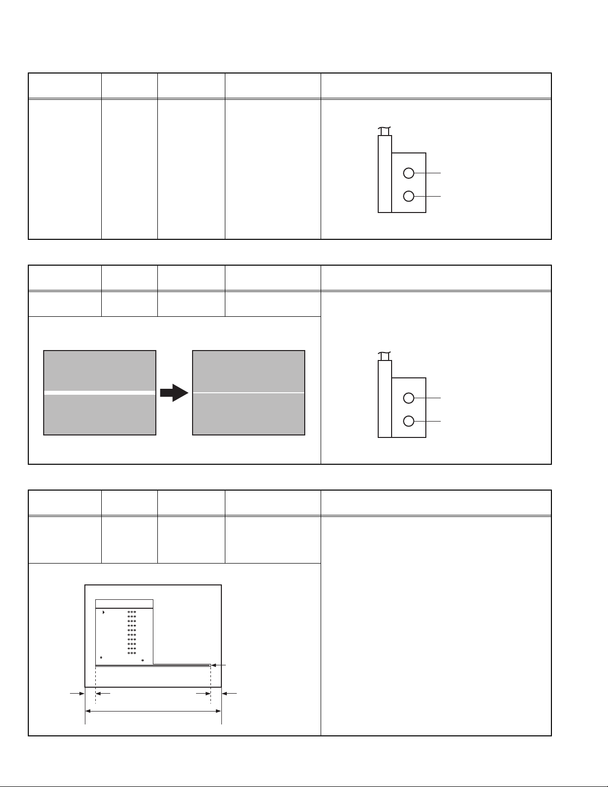
4.6.1 FOCUS ADJUSTMENT
Item
FOCUS
adjustment
Measuring
instrument
Signal
generator
Remote
control unit
4.6.2 SCREEN ADJUSTMENT
Item
SCREEN
adjustment
Measuring
instrument
Remote
control unit
Test point Adjustment part Description
FOCUS VR
[On the FBT]
(1) Receive a PAL crosshatch signal.
(2) Adjust FOCUS VR on the FBT as thin as possible.
FOCUS VR
SCREEN VR
FBT
Test point Adjustment part Description
SCREEN VR
[On the FBT]
(1) Enter the SERVICE MODE.
(2) Press the [YELLOW] key to disable vertical scan.
(3) Adjust SCREEN VR. on the FBT as thin as possible.
(4) Press [YELLOW] key again to enable vertical scan.
(5) Press [STANDARD] key to leave service menu.
4.6.3 OSD ADJUSTMENT
Item
OSD
HORIZONTAL
Measuring
instrument
Remote
control unit
POSITION
adjustment
SERVICE MENU SCREEN
JVCAK30/37 B20
OSD
IF1
IF2
IF3
IF4
AGC
VLIN
RGBH
VSOF
VPOF
: 1 1 AVL
FOCUS VR
SCREEN VR
FBT
Test point Adjustment part Description
OSD (1) Enter the SERVICE MODE.
(2) Select OSD with the []/[] key.
(3) Adjust the OSD horizontal position with the []/[]
key, which shifts the reference bar on the bottom of
the SERVICE MENU horizontally, so that the OSD is
positioned on the screen center. (X=X')
Reference ba
XX'
1-14 (No.YA080)
Screen size
Page 15
4.6.4 IF ADJUSTMENT
Item
Measuring
instrument
Test point Adjustment part Description
IF adjustment Remote
control unit
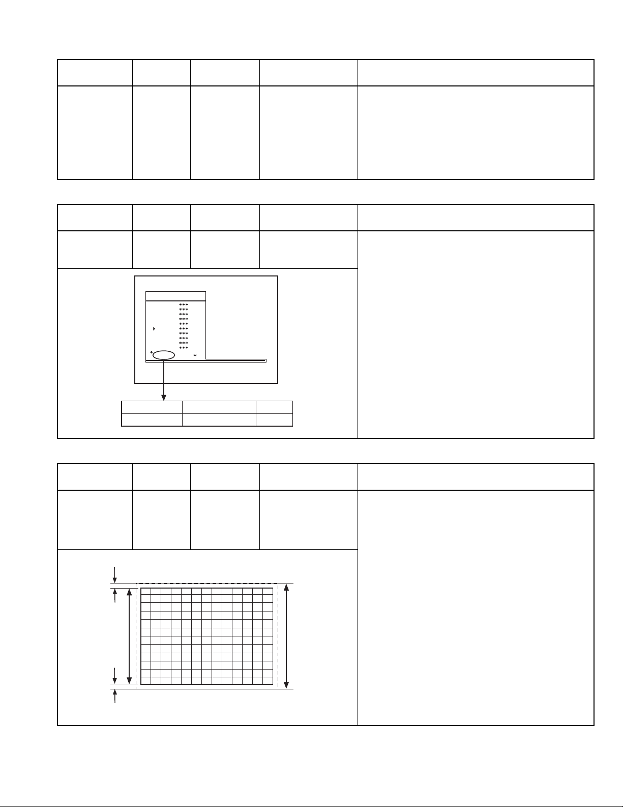
4.6.5 AGC AUTOMATICALLY ADJUSTMENT
Item
AGC
AUTOMATICALLY
Measuring
instrument
Remote
control unit
Test point Adjustment part Description
adjustment
JVCAK30/37 B20
OSD
IF1
IF2
IF3
IF4
AGC
VLIN
RGBH
VSOF
VPOF
: 1 1 AVL
IF1
IF2
IF3
IF4
(1) Receive a PAL colour bar pattern.
(2) Enter the SERVICE MODE.
(3) Select IF 1 with the []/[] key.
(4) Press [BLUE] key during IF 1 is highlighted, IF 1 and
IF 2 values are adjusted automatically by software.
(5) If the standard is L-prime, IF 3 and IF 4 values are
adjustment automatically when [BLUE] key is
pressed during IF 1 is highlighted.
AGC (1) Receive a 60dBµV RF signal level.
(2) Enter the SERVICE MODE.
(3) Select AGC with the []/[] key.
(4) Press [BLUE] key.
(5) The adjustment will be done automatically by
software.
(6) See the AGC indicator on SERVICE MENU, it must
be "1".
(7) Check that picture is normal at 90dBµV signal level.
IF INDICATOR AGC INDIXATOR NON
:11
4.6.6 DEFLECTION ADJUSTMENT
Item
VERTICAL
SIZE OFFSET
Measuring
instrument
Signal
generator
(60Hz)
adjustment
Remote
control unit
Very close
Screen
size
Test point Adjustment part Description
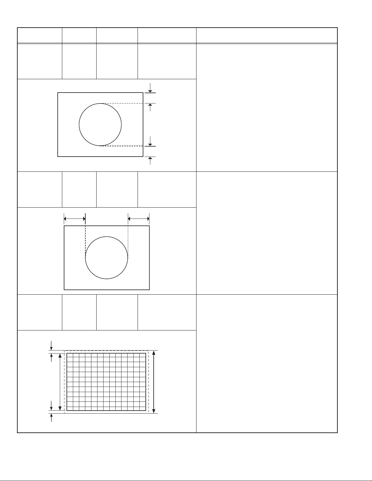
VSOF (1) Receive a NTSC crosshatch pattern of vertical
frequency 60Hz.
(2) Enter the SERVICE MODE.
(3) Select VSOF with the []/[] key.
(4) Adjust VSOF with the []/[] key until the horizontal
black lines on both the upper and lower part of the
pattern become very close to the upper and lower
horizontal sides of picture size and nearly about to
disappear.
(5) Check and readjust VSOF item if the adjustment
becomes improper after some other geometric
Picture
size
100%
adjustments are done.
Very close
(No.YA080)1-15
Page 16
Item
VERTICAL
POSITION
OFFSET
(60Hz)
adjustment
Measuring
instrument
Signal
generator
Remote
control unit
Test point Adjustment part Description
VPOF (1) Receive a NTSC circle pattern of vertical frequency
60Hz.
(2) Enter the SERVICE MODE.
(3) Select VPOF with the []/[] key.
(4) Adjust VPOF with the []/[] key until the picture is
vertically centered. (C=D)
(5) Check and readjust vertical position item if the
C
adjustment becomes improper after some other
geometric adjustments are done.
D
HORIZONTAL
POSITION
OFFSET
(60Hz)
adjustment
VERTICAL
SIZE
(50Hz)
adjustment
Very close
Screen
size
Signal
HPOF (1) Receive a NTSC circle pattern signal of vertical
generator
Remote
control unit
EF
Signal
VSIZ (1) Receive a PAL crosshatch pattern of vertical
generator
Remote
control unit
Picture
size
100%
frequency 60Hz.
(2) Enter the SERVICE MODE.
(3) Select HPOF with the []/[] key.
(4) Adjust HPOF with the []/[] key until the circle
pattern is horizontally centered. (E=F)
(5) Check and readjust a horizontal position item if the
adjustment becomes improper after some other
geometric adjustments are done. Press the [MENU]
key and memorize the set value.
frequency 50Hz.
(2) Enter the SERVICE MODE.
(3) Press the [GREEN] key to enter the GEOMETRY
MENU.
(4) Select VSIZ (Vertical size) with the []/[] key.
(5) Adjust VSIZ with the []/[] key until the horizontal
black lines on both the upper and lower horizontal
sides of picture size and nearly about to disappear.
(6) Check and readjust VSIZ item if the adjustment
becomes improper after some other geometric
adjustments are done.
Very close
1-16 (No.YA080)
Page 17

Item
VERTICAL
POSITION
(50Hz)
adjustment
Measuring
instrument
Signal
generator
Remote
control unit
Test point Adjustment part Description
VPOS (1) Receive a PAL circle pattern signal of vertical
frequency 50Hz.
(2) Enter the GEOMETRY MODE.
(3) Select VPOS (Vertical position) with the []/[] key.
(4) Adjust VPOS with the []/[] key until the circle
pattern is vertically centered. (A=B)
(5) Check and readjust VPOS item if the adjustment
A
becomes improper after some other geometric
adjustments are done.
B
HORIZONTAL
POSITION
(50Hz)
adjustment
VERTICAL
LINEARITY
adjustment
Signal
generator
Remote
control unit
CD
Signal
generator
Remote
control unit
HPOS (1) Receive a PAL circle pattern signal of vertical
VLIN (1) Receive a PAL circle pattern .
frequency 50Hz.
(2) Enter the GEOMETRY MODE.
(3) Select HPOS (Horizontal position) with the []/[]
key.
(4) Adjust HPOS with the []/[] key until the circle
pattern is horizontally centered. (C=D)
(5) Check and readjust HPOS item if the adjustment
becomes improper after some other geometric
adjustments are done.
(2) Enter the SERVICE MODE.
(3) Select VLIN with the []/[] key.
(4) Adjust VLIN with the []/[] key until circle as round
as possible.
(No.YA080)1-17
Page 18

Item
RGB MODE
HORIZONTAL
SHIFT
adjustment
Measuring
instrument
Signal
generator
Remote
control unit
Test point Adjustment part Description
AB
4.6.7 WHITE BALANCE ADJUSTMENT
Item
WHITE
BALANCE
(Low light)
adjustment
WHITE
BALANCE
(High light)
adjustment
Measuring
instrument
Signal
generator
Remote
control unit
Signal
generator
Remote
control unit
Test point Adjustment part Description
RGBH (1) Input R/G/B circle pattern signal via video input
terminal.
(2) Press [AV] key, force the TV to RGB mode.
(3) Enter the SERVICE MODE.
(4) Select RGBH with the []/[] key.
(5) Adjust RGBH with the []/[] key until the circle
pattern is horizontally centered. (A=B)
(6) Check and readjust RGBH item if the adjustment
becomes improper after some other geometric
adjustments are done.
WR
WG
WB
BR
BG
(1) Receive a black & white signal (colour off).
(2) Enter the SERVICE MODE.
(3) Select WR / WG / WB with the []/[] key
respectively.
(4) Adjust WR / WG / WB with the []/[] key,
respectively, until the white part turns to pure white
without any other colour.
(1) Receive a black & white signal (colour off).
(2) Enter the SERVICE MODE.
(3) Select BR / BG with the []/[] key respectively.
(4) Adjust BR / BG with the []/[] key, respectively
until the white part of screen make white colour.
1-18 (No.YA080)
Page 19

SECTION 5
TROUBLESHOOTING
This service manual does not describe TROUBLESHOOTING.
(No.YA080)1-19
Page 20

Victor Company of Japan, Limited
AV & MULTIMEDIA COMPANY VIDEO DISPLAY CATEGORY 12, 3-chome, Moriya-cho, kanagawa-ku, Yokohama, kanagawa-prefecture, 221-8528, Japan
(No.YA080)
Printed in Japan
VPT
Page 21

AV-20RM4SE, AV-21RM4SE
AV-21RM4SN, AV-21RM4SP
STANDARD CIRCUIT DIAGRAM
CONTENTS
BLOCK DIAGRAM
CIRCUIT DIAGRAMS
MAIN PWB CIRCUIT DIAGRAM
HEADPHONE JACK PWB CIRCUIT DIAGRAM
FRONT AV JACK PWB CIRCUIT DIAGRAM
PATTERN DIAGRAMS
MAIN PWB PATTERN
HEADPHONE JACK PWB PATTERN
FRONT AV JACK
PWB PATTERN
USING P.W. BOARD
P.W.B ASS'Y name
MAIN PWB
FRONT AV JACK PWB
HEADPHONE JACK PWB
AV-20RM4SE
VE-20161051
VE-20166161
VE-20165426
AV-21RM4SE
VE-20161048
2-3
2-5
2-18
2-19
2-21
2-23
2-24
AV-21RM4SN AV-21RM4SP
VE-20161045 VE-20161041
(No.YA080)2-1
Page 22

2-2(No.YA080)
Page 23

BLOCK DIAGRAM
L
TU201
PLL/VST TUNER
SERVICE
CONNECTOR
IC500
EEPROM
(MEMORY)
I2 C
IC501
CONTROLLER
AUDIO
IF
OUT
IC403
VIDEO PROCESSOR
IC401(MONO)
AUDIO AMP
R
IC701
HP AMP
CRT
IC900
RGB AMP
AC IN
KEYPAD
IR
SENSOR
IC800
SMPS
+115V B+
+12V
+8V
+5V
+5V STBY
VIDEO
SWITCHING
CIRCUITS
SCART1
FAV
IC600
VER AMP
Q603
HOR DRIVE
VER. DEFL.
HOR. DEFL.
TR601
FBT
2-4(No.YA080)(No.YA080)2-3
Page 24

CIRCUIT DIAGRAMS
MAIN PWB CIRCUIT DIAGRAM (1/7)
MAIN PWB ASS'Y (1/7)
VE-20161045 (AV-21RM4SN)
VE-20161041 (AV-21RM4SP)
VE-20161048 (AV-21RM4SE)
VE-20161051 (AV-20RM4SE)
(No.YA080)2-5 2-6(No.YA080)
Page 25

MAIN PWB CIRCUIT DIAGRAM (2/7)
MAIN PWB ASS'Y (2/7)
VE-20161045 (AV-21RM4SN)
VE-20161041 (AV-21RM4SP)
VE-20161048 (AV-21RM4SE)
VE-20161051 (AV-20RM4SE)
2-8(No.YA080)(No.YA080)2-7
Page 26

MAIN PWB CIRCUIT DIAGRAM (3/7)
MAIN PWB ASS'Y (3/7)
VE-20161045 (AV-21RM4SN)
VE-20161041 (AV-21RM4SP)
VE-20161048 (AV-21RM4SE)
VE-20161051 (AV-20RM4SE)
(No.YA080)2-9 2-10(No.YA080)
Page 27

MAIN PWB CIRCUIT DIAGRAM (4/7)
MAIN PWB ASS'Y (4/7)
VE-20161045 (AV-21RM4SN)
VE-20161041 (AV-21RM4SP)
VE-20161048 (AV-21RM4SE)
VE-20161051 (AV-20RM4SE)
FBT
2-12(No.YA080)(No.YA080)2-11
Page 28

MAIN PWB CIRCUIT DIAGRAM (5/7)
SW TRANSFORMER
MAIN PWB ASS'Y (5/7)
VE-20161045 (AV-21RM4SN)
VE-20161041 (AV-21RM4SP)
VE-20161048 (AV-21RM4SE)
VE-20161051 (AV-20RM4SE)
POWER REG.
(No.YA080)2-13 2-14(No.YA080)
Page 29

MAIN PWB CIRCUIT DIAGRAM (6/7)
MAIN PWB ASS'Y (6/7)
VE-20161045 (AV-21RM4SN)
VE-20161041 (AV-21RM4SP)
VE-20161048 (AV-21RM4SE)
VE-20161051 (AV-20RM4SE)
2-16(No.YA080)(No.YA080)2-15
Page 30

MAIN PWB CIRCUIT DIAGRAM (7/7)
MAIN PWB ASS'Y (7/7)
VE-20161045 (AV-21RM4SN)
VE-20161041 (AV-21RM4SP)
VE-20161048 (AV-21RM4SE)
VE-20161051 (AV-20RM4SE)
(No.YA080)2-17 2-18(No.YA080)
Page 31

HEADPHONE JACK PWB CIRCUIT DIAGRAM
FRONT AV JACK PWB CIRCUIT DIAGRAM
HEADPHONE JACK PWB
VE-20165426
FRONT AV JACK PWB
VE-20166161
2-20(No.YA080)(No.YA080)2-19
Page 32

PATTERN DIAGRAMS
MAIN PWB PATTERN
FRONT
()
CRT SOCKET PWB PATTERN
(Within MAIN PWB)
()
TOP
()
(No.YA080)2-21 2-22(No.YA080)
Page 33

HEADPHONE JACK PWB PATTERN
TOP
(No.YA080)2-23
Page 34

FRONT AV JACK PWB PATTERN
TOP
2-24(No.YA080)
Page 35

PARTS LIST
CONTENTS
USING P.W. BOARD & REMOTE CONTROL UNIT ................................................................................................... 3-1
EXPLODED VIEW PARTS LIST ................................................................................................................................. 3-2
EXPLODED VIEW ....................................................................................................................................................... 3-3
PRINTED WIRING BOARD PARTS LIST [AV-20RM4SE] ......................................................................................... 3-4
MAIN P.W. BOARD ASS’Y (VE-20161051)........................................................................................................ 3-4
FRONT AV JACK P.W. BOARD ASS’Y (VE-20166161) [COMMON)] ............................................................... 3-6
HEADPHONE JACK P.W. BOARD ASS’Y (VE-20165426)[COMMON] ............................................................ 3-6
PRINTED WIRING BOARD PARTS LIST [AV-21RM4SE] ......................................................................................... 3-7
MAIN P.W. BOARD ASS’Y (VE-20161048) ....................................................................................................... 3-7
PRINTED WIRING BOARD PARTS LIST [AV-21RM4SN] ....................................................................................... 3-10
MAIN P.W. BOARD ASS’Y (VE-20161045) ..................................................................................................... 3-10
PRINTED WIRING BOARD PARTS LIST [AV-21RM4SP] ....................................................................................... 3-13
MAIN P.W. BOARD ASS’Y (VE-20161041) ..................................................................................................... 3-13
PACKING PARTS LIST ............................................................................................................................................. 3-16
PACKING ................................................................................................................................................................... 3-17
USING P.W. BOARD & REMOTE CONTROL UNIT
P.W.B ASS’Y name AV-20RM4SE AV-21RM4SE AV-21RM4SN AV-21RM4SP
MAIN P.W.B (with CRT SOCKET P.W.B) VE-20161051 VE-20161048 VE-20161045 VE-20161041
FRONT AV JACK P.W.B VE-20166161 ←←←
HEADPHONE JACK P.W.B VE-20165426 ←←←
REMOTE CONTROL UNIT
VE-30017763
(RM-C1100)
←←←
(No.YA080)3-1
Page 36

EXPLODED VIEW PARTS LIST
[ AV-20RM4SE ]
Ref.No. Part No. Part Name Description Local
V01 VE-30002748 PICTURE TUBE(ITC) Inc. DY, PC MAGNET
L01 VE-30002119 DEG COIL&EARTH CB.
TR601 VE-30017788 TRF FBT within MAIN PWB
1 VE-20160402 BUTTON ON/OFF
2 VE-35000013 SPRING ON/OFF SWITCH
3 VE-20004338 LENS PRE-AMP
4 VE-20167108 LENS
5 VE-20056446 LENS LED
6 VE-20165665 FRONT CABINET
7 VE-20160401 BUTTON FUNCTION
8 VE-40013593 LOGO JVC
9 VE-30026953 SPEAKER (x2) 16
10 VE-20160396 BACK COVER
11 VE-35010702 SCREW (4x20) (x6)
12 VE-20165670 LABEL
13 VE-30029498 POWERCORD 2.2MT
14 VE-20004520 CABLE HOLDER
15 VE-20004646 FOOT RUBBER (x2)
[ AV-21RM4SE , AV-21RM4SN , AV-21RM4SP ]
Ref.No. Part No. Part Name Description Local
V01 VE-30002749 PICTURE TUBE (ITC) Inc. DY, PC MAGNET
L01 VE-30002124 DEG COIL&EARTH CB.
TR601 VE-30017788 TRF FBT within MAIN PWB
1 VE-20160402 BUTTON ON/OFF
2 VE-35000013 SPRING ON/OFF SWITCH
3 VE-20053831 LENS PRE-AMP
4 VE-20167108 LENS
5 VE-20056446 LENS LED
6 VE-20165671 FRONT CABINET
7 VE-20160401 BUTTON FUNCTION
8 VE-40013593 LOGO JVC
9 VE-30026953 SPEAKER (x2) 16Ω 10W (57x126MM)
10 VE-20160396 BACK COVER
11 VE-35010702 SCREW (4x20) (x6)
12 VE-20165678 LABEL AV-21RM4SN
12 VE-20165569 LABEL AV-21RM4SP
12 VE-20165675 LABEL AV-21RM4SE
13 VE-30029498 POWER CORD 2.2MT
14 VE-20004520 CABLE HOLDER
15 VE-20004646 FOOT RUBBER (x2)
Ω
10W (57x126MM)
3-2(No.YA080)
Page 37

EXPLODED VIEW
13
10
11
(x6)
12
L01
V01
CRT SOCKET PWB
(within MAIN PWB)
9
6
14
8
2
1
3
4
7
FRONT AV JACK
PWB
TR601
MAIN PWB
5
15
HEADPHONE JACK
PWB
(No.YA080)3-3
Page 38

PRINTED WIRING BOARD PARTS LIST [AV-20RM4SE]
MAIN P.W. BOARD ASS’Y (VE-20161051)
Ref No. Part No. Part Name Description Local
IC118 VE-30023137 IC
IC401 VE-30013986 IC
IC403 VE-30026922 IC
IC500 VE-20161050 IC (MEMORY)
IC501 VE-20091454 IC (MICOM)
IC502 VE-30001670 PREAMPLIFIER
IC600 VE-30015306 IC
IC800 VE-30011968 IC
IC801 VE-30015087 IC
IC803 VE-30001500 IC
IC804 VE-30001622 IC
IC806 VE-30014346 IC
IC900 VE-30025172 IC
Q101 VE-30001457 TRANSISTOR
Q103 VE-30001457 TRANSISTOR
Q104 VE-30001457 TRANSISTOR
Q105 VE-30001457 TRANSISTOR
Q301 VE-30001458 TRANSISTOR
Q302 VE-30001457 TRANSISTOR
Q406 VE-30001457 TRANSISTOR
Q503 VE-30001457 TRANSISTOR
Q504 VE-30001458 TRANSISTOR
Q601 VE-30013656 TRANSISTOR POWER
Q603 VE-30001448 TRANSISTOR H.OUT
Q604 VE-30001457 TRANSISTOR
Q606 VE-30001457 TRANSISTOR
Q801 VE-30001386 TRANSISTOR
Q802 VE-30001457 TRANSISTOR
Q804 VE-30001454 TRANSISTOR
D101 VE-30007760 DIODE ZENER
D102 VE-30007760 DIODE ZENER
D103 VE-30007760 DIODE ZENER
D104 VE-30007762 DIODE ZENER
D106 VE-30001377 DIODE ZENER
D300 VE-30001285 DIODE
D301 VE-30001285 DIODE
D405 VE-30007763 DIODE ZENER
D407 VE-30001284 DIODE
D408 VE-30001285 DIODE
D409 VE-30007760 DIODE ZENER
D410 VE-30007760 DIODE ZENER
D411 VE-30007760 DIODE ZENER
D501 VE-30001285 DIODE
D505 VE-30001285 DIODE
D506 VE-30001284 DIODE
D509 VE-30001279 LED
D512 VE-30001285 DIODE
D513 VE-30001339 DIODE ZENER
D602 VE-30001329 DIODE
D603 VE-30001285 DIODE
D608 VE-30001318 DIODE
D609 VE-30001318 DIODE
D610 VE-30001318 DIODE
D611 VE-30001285 DIODE
D614 VE-30001318 DIODE
D615 VE-30001285 DIODE
D616 VE-30009699 DIODE ZENER
D619 VE-30009699 DIODE ZENER
D620 VE-30003722 DIODE ZENER
D800 VE-30001318 DIODE
D801 VE-30001347 DIODE ZENER
D802 VE-30001318 DIODE
D803 VE-30001315 DIODE
D804 VE-30001285 DIODE
D805 VE-30001315 DIODE
D806 VE-30001315 DIODE
D808 VE-30007681 DIODE
D809 VE-30001329 DIODE
D810 VE-30009366 DIODE
D811 VE-30001329 DIODE
D812 VE-30001285 DIODE
D813 VE-30001329 DIODE
D837 VE-30001329 DIODE
D838 VE-30001329 DIODE
D889 VE-30001384 TRANSISTOR
D890 VE-30001329 DIODE
D893 VE-30001329 DIODE
D894 VE-30001329 DIODE
D900 VE-30001318 DIODE
Ref No. Part No. Part Name Description Local
D901 VE-30001318 DIODE
D902 VE-30001318 DIODE
D903 VE-30001344 DIODE ZENER
C101 VE-30016654 CAP SMD 100NF 16V K R
C108 VE-30000371 CAP EL 22UF 50V M
C114 VE-30016654 CAP SMD 100NF 16V K R
C142 VE-30000384 CAP EL 2.2UF 50V M
C143 VE-30012583 CAP SMD 1.5NF 50V K
C144 VE-30012583 CAP SMD 1.5NF 50V K
C145 VE-30012589 CAP SMD 4.7NF 50V K
C155 VE-30012560 CAP SMD 100PF 50V J
C159 VE-30012560 CAP SMD 100PF 50V J
C160 VE-30000387 CAP EL 33UF 50V M
C166 VE-30012559 CAP SMD 10PF 50V D
C201 VE-30000400 CAP EL 47UF 50V M
C205 VE-30000371 CAP EL 22UF 50V M
C206 VE-30012610 CAP SMD 10NF 50V J
C207 VE-30012610 CAP SMD 10NF 50V J
C300 VE-30000400 CAP EL 47UF 50V M
C302 VE-30000092 CAP MKT 220NF 63V J
C408 VE-30012586 CAP SMD 22NF 50V K
C409 VE-30000345 CAP EL 10UF 50V M
C410 VE-30000384 CAP EL 2.2UF 50V M
C411 VE-30000345 CAP EL 10UF 50V M
C412 VE-30012586 CAP SMD 22NF 50V K
C413 VE-30000362 CAP EL 1UF 50V M
C414 VE-30012585 CAP SMD 2.2NF 50V K R
C415 VE-30012581 CAP SMD 1NF 50V K R
C416 VE-30000362 CAP EL 1UF 50V M
C417 VE-30000362 CAP EL 1UF 50V M
C418 VE-30012586 CAP SMD 22NF 50V K
C419 VE-30000413 CAP EL 4.7UF 50V M
C420 VE-30000100 CAP MKT 330NF 63V J
C422 VE-30000400 CAP EL 47UF 50V M
C423 VE-30000400 CAP EL 47UF 50V M
C424 VE-30000345 CAP EL 10UF 50V M
C425 VE-30012586 CAP SMD 22NF 50V K
C426 VE-30016654 CAP SMD 100NF 16V K R
C427 VE-30016654 CAP SMD 100NF 16V K R
C429 VE-30012589 CAP SMD 4.7NF 50V K
C431 VE-30000362 CAP EL 1UF 50V M
C432 VE-30012586 CAP SMD 22NF 50V K
C433 VE-30000345 CAP EL 10UF 50V M
C434 VE-30016654 CAP SMD 100NF 16V K R
C435 VE-30016654 CAP SMD 100NF 16V K R
C436 VE-30000109 CAP MKT 470NF 63V J
C437 VE-30016654 CAP SMD 100NF 16V K R
C438 VE-30016654 CAP SMD 100NF 16V K R
C439 VE-30016654 CAP SMD 100NF 16V K R
C440 VE-30000074 CAP MKT 100NF 63V J
C441 VE-30012582 CAP SMD 10NF 50V K R
C443 VE-30000362 CAP EL 1UF 50V M
C444 VE-30000384 CAP EL 2.2UF 50V M
C448 VE-30012586 CAP SMD 22NF 50V K
C449 VE-30012567 CAP SMD 220PF 50V J
C452 VE-30012581 CAP SMD 1NF 50V K R
C454 VE-30012573 CAP SMD 47PF 50V J
C455 VE-30012573 CAP SMD 47PF 50V J
C456 VE-30012573 CAP SMD 47PF 50V J
C459 VE-30012575 CAP SMD 4.7PF 50V C CH
C460 VE-30000345 CAP EL 10UF 50V M
C502 VE-30000396 CAP EL 47UF 16V M
C504 VE-30012586 CAP SMD 22NF 50V K
C505 VE-30012589 CAP SMD 4.7NF 50V K
C510 VE-30012586 CAP SMD 22NF 50V K
C511 VE-30012566 CAP SMD 22PF 50V J
C513 VE-30000371 CAP EL 22UF 50V M
C514 VE-30012586 CAP SMD 22NF 50V K
C515 VE-30012579 CAP SMD 82PF 50V J
C517 VE-30012586 CAP SMD 22NF 50V K
C518 VE-30012586 CAP SMD 22NF 50V K
C519 VE-30000352 CAP EL 100UF 16V M
C520 VE-30012560 CAP SMD 100PF 50V J
C521 VE-30012562 CAP SMD 15PF 50V J
C522 VE-30012562 CAP SMD 15PF 50V J
C523 VE-30012585 CAP SMD 2.2NF 50V K R
C525 VE-30012566 CAP SMD 22PF 50V J
C530 VE-30012589 CAP SMD 4.7NF 50V K
C531 VE-30000384 CAP EL 2.2UF 50V M
C532 VE-30012586 CAP SMD 22NF 50V K
C536 VE-30000074 CAP MKT 100NF 63V J
C541 VE-30000109 CAP MKT 470NF 63V J
C542 VE-30000205 CAP CER 150PF 50V J SL
3-4(No.YA080)
Page 39

Ref No. Part No. Part Name Description Local
Ref No. Part No. Part Name Description Local
C543 VE-30000205 CAP CER 150PF 50V J SL
C545 VE-30012607 CAP SMD 150PF 50V J
C603 VE-30000384 CAP EL 2.2UF 50V M
C604 VE-30000345 CAP EL 10UF 50V M
C608 VE-30000107 CAP MKT 47NF 250V J
C610 VE-30000355 CAP EL 100UF 50V M
C611 VE-30000092 CAP MKT 220NF 63V J
C613 VE-30016085 CAP EL 10UF 63V 105°
C615 VE-30000359 CAP EL 1000UF 16V M
C616 VE-30000352 CAP EL 100UF 16V M
C618 VE-30007100 CAP MKP 10NF 1600Vdc / 1250Vpp %3.5
C619 VE-30000131 CAP MKP 100NF 250V J
C623 VE-30000404 CAP EL 47UF 160V M (HR) 105°
C624 VE-30000350 CAP EL 10UF 250V M
C627 VE-30000152 CAP MKP 330NF 250V J
C628 VE-30018380 CAP EL 3.3UF 160V M 105°
C631 VE-30000410 CAP EL 470UF 50V M
C632 VE-30000100 CAP MKT 330NF 63V J
C633 VE-30016085 CAP EL 10UF 63V 105°
C634 VE-30000409 CAP EL 470UF 25V M
C635 VE-30000100 CAP MKT 330NF 63V J
C636 VE-30000387 CAP EL 33UF 50V M
C638 VE-30012581 CAP SMD 1NF 50V K R
C639 VE-30000431 CAP CER 100PF 1KV M
C641 VE-30000345 CAP EL 10UF 50V M
C642 VE-30012609 CAP SMD 68NF 50V K
C643 VE-30000116 CAP MKT 68NF 63V J
C644 VE-30000362 CAP EL 1UF 50V M
C801 VE-30000094 CAP MKT 220NF 275V M AC
C802 VE-30000094 CAP MKT 220NF 275V M AC
C803 VE-30000433 CAP CER 1NF 1KV M B
C804 VE-30000433 CAP CER 1NF 1KV M B
C808 VE-30000295 CAP CER 100NF 50V Z F
C809 VE-30000418 CAP EL 100UF 400V M
C810 VE-30000387 CAP EL 33UF 50V M
C811 VE-30000161 CAP MKP 47NF 630Vdc / 622Vpp J
C812 VE-30009208 CAP CER 470PF 1KV K
C813 VE-30000295 CAP CER 100NF 50V Z F
C816 VE-30000447 CAP CER 4.7NF 4KV M E
C817 VE-30000198 CAP CER 120PF 500V J SL
C818 VE-30016654 CAP SMD 100NF 16V K R
C819 VE-30012609 CAP SMD 68NF 50V K
C824 VE-30000433 CAP CER 1NF 1KV M B
C826 VE-30000404 CAP EL 47UF 160V M (HR) 105°
C827 VE-30000411 CAP EL 4700UF 16V M
C828 VE-30000295 CAP CER 100NF 50V Z F
C829 VE-30000407 CAP EL 470UF 16V M
C830 VE-30000382 CAP EL 2200UF 16V M
C832 VE-30000295 CAP CER 100NF 50V Z F
C833 VE-30000409 CAP EL 470UF 25V M
C834 VE-30000295 CAP CER 100NF 50V Z F
C836 VE-30000431 CAP CER 100PF 1KV M
C838 VE-30000352 CAP EL 100UF 16V M
C839 VE-30000352 CAP EL 100UF 16V M
C840 VE-30000352 CAP EL 100UF 16V M
C843 VE-30000431 CAP CER 100PF 1KV M
C848 VE-30000352 CAP EL 100UF 16V M
C849 VE-30000352 CAP EL 100UF 16V M
C850 VE-30000352 CAP EL 100UF 16V M
C855 VE-30000407 CAP EL 470UF 16V M
C857 VE-30012573 CAP SMD 47PF 50V J
C858 VE-30007308 CAP CER 220PF 1KV K
C862 VE-30000367 CAP EL 1UF 250V M
C863 VE-30000433 CAP CER 1NF 1KV M B
C907 VE-30000434 CAP CER 1NF 2KV K B
C908 VE-30000415 CAP EL 4.7UF 250V M
C912 VE-30000075 CAP MKT 100NF 250V K (DC)
NOT1 VE-30000352 CAP EL 100UF 16V M
X403 VE-30000074 CAP MKT 100NF 63V J
R101 VE-30012509 RES SMD 1/16W 100K J
R104 VE-30000594 RES CF 1/4W 22K J
R105 VE-30000792 RES CF 1/4W 75R J
R108 VE-30000723 RES CF 1/4W 47K J
R109 VE-30012713 RES SMD 1/16W 75R J
R110 VE-30012713 RES SMD 1/16W 75R J
R113 VE-30012713 RES SMD 1/16W 75R J
R114 VE-30012713 RES SMD 1/16W 75R J
R115 VE-30012713 RES SMD 1/16W 75R J
R116 VE-30012987 RES SMD 1/16W 56R J
R117 VE-30012713 RES SMD 1/16W 75R J
R118 VE-30000792 RES CF 1/4W 75R J
R122 VE-30000792 RES CF 1/4W 75R J
R123 VE-30000792 RES CF 1/4W 75R J
R125 VE-30012657 RES SMD 1/16W 1K J
R126 VE-30012695 RES SMD 1/16W 470R J
R127 VE-30000459 RES CF 1/4W 100R J
R128 VE-30000471 RES CF 1/4W 10K J
R129 VE-30012713 RES SMD 1/16W 75R J
R130 VE-30000594 RES CF 1/4W 22K J
R132 VE-30000723 RES CF 1/4W 47K J
R133 VE-30000718 RES CF 1/4W 4.7K J
R135 VE-30012657 RES SMD 1/16W 1K J
R153 VE-30012657 RES SMD 1/16W 1K J
R201 VE-30012674 RES SMD 1/16W 27K J
R202 VE-30012692 RES SMD 1/16W 4.7K J
R204 VE-30000459 RES CF 1/4W 100R J
R206 VE-30000459 RES CF 1/4W 100R J
R301 VE-30000471 RES CF 1/4W 10K J
R302 VE-30000471 RES CF 1/4W 10K J
R303 VE-30012641 RES SMD 1/16W 10K J
R305 VE-30012641 RES SMD 1/16W 10K J
R306 VE-30012509 RES SMD 1/16W 100K J
R417 VE-30012510 RES SMD 1/16W 100R J
R418 VE-30012510 RES SMD 1/16W 100R J
R419 VE-30012649 RES SMD 1/16W 150R J
R420 VE-30000466 RES CF 1/4W 1K J
R421 VE-30012650 RES SMD 1/16W 15K J
R422 VE-30012659 RES SMD 1/16W 2.2K J
R423 VE-30012712 RES SMD 1/16W 8.2K J
R424 VE-30000712 RES CF 1/4W 470R J
R425 VE-30000583 RES CF 1/4W 220R J
R426 VE-30012659 RES SMD 1/16W 2.2K J
R427 VE-30012674 RES SMD 1/16W 27K J
R428 VE-30000792 RES CF 1/4W 75R J
R431 VE-30012674 RES SMD 1/16W 27K J
R432 VE-30012657 RES SMD 1/16W 1K J
R433 VE-30012667 RES SMD 1/16W 220K J
R437 VE-30000466 RES CF 1/4W 1K J
R438 VE-30000466 RES CF 1/4W 1K J
R439 VE-30012657 RES SMD 1/16W 1K J
R440 VE-30012714 RES SMD 1/16W 820R J
R441 VE-30012656 RES SMD 1/16W 18K J
R442 VE-30000466 RES CF 1/4W 1K J
R446 VE-30012714 RES SMD 1/16W 820R J
R447 VE-30012714 RES SMD 1/16W 820R J
R448 VE-30012683 RES SMD 1/16W 330K J
R449 VE-30012662 RES SMD 1/16W 2.7K J
R450 VE-30000712 RES CF 1/4W 470R J
R454 VE-30000594 RES CF 1/4W 22K J
R455 VE-30012656 RES SMD 1/16W 18K J
R458 VE-30012662 RES SMD 1/16W 2.7K J
R459 VE-30012510 RES SMD 1/16W 100R J
R460 VE-30012510 RES SMD 1/16W 100R J
R461 VE-30012510 RES SMD 1/16W 100R J
R469 VE-30000670 RES CF 1/4W 330K J
R470 VE-30012683 RES SMD 1/16W 330K J
R475 VE-30012510 RES SMD 1/16W 100R J
R476 VE-30012707 RES SMD 1/16W 680R J
R477 VE-30014022 RES SMD 1/16W 47R J
R502 VE-30012695 RES SMD 1/16W 470R J
R503 VE-30012707 RES SMD 1/16W 680R J
R504 VE-30012679 RES SMD 1/16W 3.9K J
R505 VE-30012673 RES SMD 1/16W 270R J
R506 VE-30012506 RES SMD 1/16W 1.5K J
R507 VE-30012657 RES SMD 1/16W 1K J
R508 VE-30000706 RES CF 1/4W 47R J
R509 VE-30012641 RES SMD 1/16W 10K J
R510 VE-30000622 RES CF 1/4W 270R J
R511 VE-30012657 RES SMD 1/16W 1K J
R512 VE-30012504 RES SMD 1/16W 1.2K J
R513 VE-30000459 RES CF 1/4W 100R J
R514 VE-30000459 RES CF 1/4W 100R J
R515 VE-30012692 RES SMD 1/16W 4.7K J
R516 VE-30012692 RES SMD 1/16W 4.7K J
R517 VE-30012692 RES SMD 1/16W 4.7K J
R518 VE-30000471 RES CF 1/4W 10K J
R519 VE-30012698 RES SMD 1/16W 5.6K J
R525 VE-30000583 RES CF 1/4W 220R J
R526 VE-30012641 RES SMD 1/16W 10K J
R527 VE-30000718 RES CF 1/4W 4.7K J
R528 VE-30012698 RES SMD 1/16W 5.6K J
R530 VE-30012698 RES SMD 1/16W 5.6K J
R531 VE-30012692 RES SMD 1/16W 4.7K J
R532 VE-30012659 RES SMD 1/16W 2.2K J
R533 VE-30012644 RES SMD 1/16W 12K J
R534 VE-30000526 RES CF 1/4W 1.5K J
R535 VE-30000718 RES CF 1/4W 4.7K J
R536 VE-30000471 RES CF 1/4W 10K J
R537 VE-30012641 RES SMD 1/16W 10K J
R545 VE-30012644 RES SMD 1/16W 12K J
R546 VE-30000590 RES CF 1/4W 2.2K J
R547 VE-30012659 RES SMD 1/16W 2.2K J
R548 VE-30012641 RES SMD 1/16W 10K J
(No.YA080)3-5
Page 40

Ref No. Part No. Part Name Description Local
Ref No. Part No. Part Name Description Local
R555 VE-30012659 RES SMD 1/16W 2.2K J
R556 VE-30012657 RES SMD 1/16W 1K J
R559 VE-30000470 RES CF 1/2W 10K J
R560 VE-30012669 RES SMD 1/16W 22K J
R561 VE-30012692 RES SMD 1/16W 4.7K J
R562 VE-30000471 RES CF 1/4W 10K J
R564 VE-30012641 RES SMD 1/16W 10K J
R601 VE-30000752 RES CF 1/4W 56K J
R602 VE-30000536 RES CF 1/4W 150K J
R605 VE-30000504 RES CF 1/4W 120K J
R612 VE-30012692 RES SMD 1/16W 4.7K J
R613 VE-30012692 RES SMD 1/16W 4.7K J
R618 VE-30012662 RES SMD 1/16W 2.7K J
R619 VE-30012641 RES SMD 1/16W 10K J
R623 VE-30000607 RES CF 1/4W 2.2R J
R624 VE-30001161 RES MO 2W 39R J
R625 VE-30000900 RES MF 1/4W 1.8K J
R627 VE-30000910 RES MF 1/2W 1.8R G
R628 VE-30000650 RES CF 1/4W 33R J
R630 VE-30000828 RES CF 1/4W 8.2M J
R631 VE-30000885 RES MF 1/4W 1.5K J
R633 VE-30000706 RES CF 1/4W 47R J
R634 VE-30012641 RES SMD 1/16W 10K J
R637 VE-30000621 RES CF 1/2W 270R J
R638 VE-30000612 RES CF 1/4W 2.4K J
R639 VE-30000718 RES CF 1/4W 4.7K J
R640 VE-30012662 RES SMD 1/16W 2.7K J
R641 VE-30012649 RES SMD 1/16W 150R J
R645 VE-30016868 RES MO 3W 2.2K J
R646 VE-30000500 RES CF 1/4W 12K J
R647 VE-30000466 RES CF 1/4W 1K J
R648 VE-30001254 RES FUSE 1/2W 0.68R J
R649 VE-30000775 RES CF 1/4W 6.8K J
R650 VE-30000744 RES CF 1/4W 560R J
R654 VE-30000705 RES CF 1/2W 47R J
R655 VE-30000705 RES CF 1/2W 47R J
R657 VE-30012656 RES SMD 1/16W 18K J
R658 VE-30001161 RES MO 2W 39R J
R659 VE-30001123 RES MO 2W 220R J
R660 VE-30012669 RES SMD 1/16W 22K J
R661 VE-30012674 RES SMD 1/16W 27K J
R662 VE-30000712 RES CF 1/4W 470R J
R663 VE-30000459 RES CF 1/4W 100R J
R665 VE-30012708 RES SMD 1/16W 68K J
R801 VE-30000982 RES MF 1/4W 4.7K J
R803 VE-30012692 RES SMD 1/16W 4.7K J
R804 VE-30000536 RES CF 1/4W 150K J
R805 VE-30000843 RES MF 1/4W 10R J
R806 VE-30000982 RES MF 1/4W 4.7K J
R807 VE-30001159 RES MO 1W 0.33R J
R809 VE-30007784 RES MO 5W 33K J
R810 VE-30001257 RES MG 1/2W 4.7M J
R811 VE-30000594 RES CF 1/4W 22K J
R813 VE-30000718 RES CF 1/4W 4.7K J
R814 VE-30012662 RES SMD 1/16W 2.7K J
R815 VE-30000452 RES CF 1/4W 10R J
R817 VE-30001037 RES MF 1/4W 99K F
R818 VE-30000925 RES MF 1/4W 2.2K F
R819 VE-30000466 RES CF 1/4W 1K J
R821 VE-30000470 RES CF 1/2W 10K J
R828 VE-30001260 RES WW 5W 2.2R J
R829 VE-30000718 RES CF 1/4W 4.7K J
R830 VE-30012657 RES SMD 1/16W 1K J
R831 VE-30012669 RES SMD 1/16W 22K J
R835 VE-30016802 RES WW 5W 5.6R J RAD
R900 VE-30006712 FERRITE BEAD
R901 VE-30006712 FERRITE BEAD
R902 VE-30006712 FERRITE BEAD
R903 VE-30000525 RES CF 1/2W 1.5K J
R904 VE-30000525 RES CF 1/2W 1.5K J
R905 VE-30000525 RES CF 1/2W 1.5K J
R906 VE-30000525 RES CF 1/2W 1.5K J
R919 VE-30001213 RES FUSE 1/4W 1R J
J107 VE-30000683 RES CF 1/4W 390R J
J108 VE-30000712 RES CF 1/4W 470R J
J271 VE-30000712 RES CF 1/4W 470R J
S142 VE-30012673 RES SMD 1/16W 270R J
J282 VE-30001992 FIXED COIL 10UH
J313 VE-30001994 FIXED COIL 22UH
L201 VE-30001979 FIXED COIL 1UH
L402 VE-30001992 FIXED COIL 10UH
L404 VE-30001990 FIXED COIL 6.8UH
L405 VE-30026042 ADJ.COIL
L601 VE-30001990 FIXED COIL 6.8UH
L603 VE-30002149 LINEARITY COIL 50UH
L803 VE-30001984 FIXED COIL 2.2UH
L807 VE-30001992 FIXED COIL 10UH
L810 VE-30001992 FIXED COIL 10UH
TR601 VE-30017788 TRF FBT
TR802 VE-30013683 TRF SMPS (170-270V)
F801 VE-30001731 FUSE 2.5A
J281 VE-30006712 FERRITE BEAD
L101 VE-30001971 FERRITE SMD
L103 VE-30001971 FERRITE SMD
L110 VE-30001971 FERRITE SMD
L111 VE-30001971 FERRITE SMD
L112 VE-30001971 FERRITE SMD
L113 VE-30001971 FERRITE SMD
L114 VE-30001971 FERRITE SMD
L116 VE-30001971 FERRITE SMD
L210 VE-30001971 FERRITE SMD
L211 VE-30001971 FERRITE SMD
L401 VE-30001971 FERRITE SMD
L403 VE-30001971 FERRITE SMD
L406 VE-30001971 FERRITE SMD
L604 VE-30001971 FERRITE SMD
L802 VE-30001971 FERRITE SMD
L805 VE-30001971 FERRITE SMD
L806 VE-30001971 FERRITE SMD
PL101 VE-30015053 SOCKET SCART
PL903 VE-30001855 SOCKET CRT
SG900 VE-30000428 SPARK GAP 300V
SG901 VE-30000428 SPARK GAP 300V
SG902 VE-30000428 SPARK GAP 300V
SW501 VE-30002178 SWITCH TACT
SW502 VE-30002178 SWITCH TACT
SW503 VE-30002178 SWITCH TACT
SW504 VE-30002178 SWITCH TACT
SW505 VE-30002178 SWITCH TACT
SW801 VE-30017848 SWITCH ON/OFF
TH800 VE-30001270 PTC 9 OHM
TR801 VE-30002100 LINE FILTER
TU201 VE-30009637 TUNER WSP (PLL)
X401 VE-30001749 XTAL
X402 VE-30015592 XTAL
X501 VE-30002851 XTAL
Z402 VE-30012544 FILTER SAW
FRONT AV JACK P.W. BOARD ASS’Y (VE-20166161)
Ref No. Part No. Part Name Description Local
D1201 VE-30001350 DIODE ZENER 12V
D1203 VE-30001350 DIODE ZENER 12V
PL1204 VE-30001882 RCA JACK 1P WHITE
PL1203 VE-30001884 RCA JACK 1P YELLOW
HEADPHONE JACK P.W. BOARD ASS’Y
(VE-20165426)
Ref No. Part No. Part Name Description Local
D100 VE-30001371 DIODE ZENER
D101 VE-30001371 DIODE ZENER
C100 VE-30000330 CAP CER 4.7NF 50V K B
C101 VE-30000330 CAP CER 4.7NF 50V K B
R100 VE-30000492 RES CF 1/4W 120R J
R101 VE-30000492 RES CF 1/4W 120R J
R102 VE-30000744 RES CF 1/4W 121R J
R103 VE-30000744 RES CF 1/4W 121R J
JK1 VE-30001900 JACK HEADPHONE HP01
3-6(No.YA080)
Page 41

PRINTED WIRING BOARD PARTS LIST [AV-21RM4SE]
MAIN P.W. BOARD ASS’Y (VE-20161048)
Ref No. Part No. Part Name Description Local
IC118 VE-30023137 IC
IC401 VE-30013986 IC
IC403 VE-30026922 IC
IC500 VE-20121218 IC (MEMORY)
IC501 VE-20091454 IC (MICOM)
IC502 VE-30001670 PREAMPLIFIER
IC600 VE-30015306 IC
IC800 VE-30011968 IC
IC801 VE-30015087 IC
IC803 VE-30001500 IC
IC804 VE-30001622 IC
IC806 VE-30014346 IC
IC900 VE-30025172 IC
Q101 VE-30001457 TRANSISTOR
Q103 VE-30001457 TRANSISTOR
Q105 VE-30001457 TRANSISTOR
Q301 VE-30001458 TRANSISTOR
Q302 VE-30001457 TRANSISTOR
Q406 VE-30001457 TRANSISTOR
Q504 VE-30001458 TRANSISTOR
Q601 VE-30013656 TRANSISTOR POWER
Q603 VE-30001448 TRANSISTOR H.OUT
Q801 VE-30001386 TRANSISTOR
Q804 VE-30001454 TRANSISTOR
D101 VE-30007760 DIODE ZENER
D102 VE-30007760 DIODE ZENER
D103 VE-30007760 DIODE ZENER
D104 VE-30007762 DIODE ZENER
D106 VE-30001377 DIODE ZENER
D300 VE-30001285 DIODE
D301 VE-30001285 DIODE
D405 VE-30007763 DIODE ZENER
D407 VE-30001284 DIODE
D408 VE-30001285 DIODE
D409 VE-30007760 DIODE ZENER
D410 VE-30007760 DIODE ZENER
D411 VE-30007760 DIODE ZENER
D501 VE-30001285 DIODE
D505 VE-30001285 DIODE
D506 VE-30001284 DIODE
D509 VE-30001279 LED
D512 VE-30001285 DIODE
D513 VE-30001339 DIODE ZENER
D602 VE-30001329 DIODE
D603 VE-30001285 DIODE
D608 VE-30001318 DIODE
D609 VE-30001318 DIODE
D610 VE-30001318 DIODE
D611 VE-30001285 DIODE
D614 VE-30001318 DIODE
D615 VE-30001285 DIODE
D616 VE-30009699 DIODE ZENER
D619 VE-30009699 DIODE ZENER
D620 VE-30003722 DIODE ZENER
D800 VE-30001318 DIODE
D801 VE-30001347 DIODE ZENER
D802 VE-30001318 DIODE
D803 VE-30001315 DIODE
D804 VE-30001285 DIODE
D805 VE-30001315 DIODE
D806 VE-30001315 DIODE
D808 VE-30007681 DIODE
D809 VE-30001329 DIODE
D810 VE-30009366 DIODE
D811 VE-30001329 DIODE
D812 VE-30001285 DIODE
D813 VE-30001329 DIODE
D837 VE-30001329 DIODE
D838 VE-30001329 DIODE
D889 VE-30001384 TRANSISTOR
D890 VE-30001329 DIODE
D893 VE-30001329 DIODE
D894 VE-30001329 DIODE
D900 VE-30001318 DIODE
D901 VE-30001318 DIODE
D902 VE-30001318 DIODE
D903 VE-30001344 DIODE ZENER
C101 VE-30016654 CAP SMD 100NF 16V K R
C108 VE-30000371 CAP EL 22UF 50V M
Ref No. Part No. Part Name Description Local
C114 VE-30016654 CAP SMD 100NF 16V K R
C142 VE-30000384 CAP EL 2.2UF 50V M
C143 VE-30012583 CAP SMD 1.5NF 50V K
C144 VE-30012583 CAP SMD 1.5NF 50V K
C145 VE-30012589 CAP SMD 4.7NF 50V K
C155 VE-30012560 CAP SMD 100PF 50V J
C159 VE-30012560 CAP SMD 100PF 50V J
C160 VE-30000387 CAP EL 33UF 50V M
C166 VE-30012559 CAP SMD 10PF 50V D
C201 VE-30000400 CAP EL 47UF 50V M
C205 VE-30000371 CAP EL 22UF 50V M
C206 VE-30012610 CAP SMD 10NF 50V J
C207 VE-30012610 CAP SMD 10NF 50V J
C300 VE-30000400 CAP EL 47UF 50V M
C302 VE-30000092 CAP MKT 220NF 63V J
C408 VE-30012586 CAP SMD 22NF 50V K
C409 VE-30000345 CAP EL 10UF 50V M
C410 VE-30000384 CAP EL 2.2UF 50V M
C411 VE-30000345 CAP EL 10UF 50V M
C412 VE-30012586 CAP SMD 22NF 50V K
C413 VE-30000362 CAP EL 1UF 50V M
C414 VE-30012585 CAP SMD 2.2NF 50V K R
C415 VE-30012581 CAP SMD 1NF 50V K R
C416 VE-30000362 CAP EL 1UF 50V M
C417 VE-30000362 CAP EL 1UF 50V M
C418 VE-30012586 CAP SMD 22NF 50V K
C419 VE-30000413 CAP EL 4.7UF 50V M
C420 VE-30000100 CAP MKT 330NF 63V J
C422 VE-30000400 CAP EL 47UF 50V M
C423 VE-30000400 CAP EL 47UF 50V M
C424 VE-30000345 CAP EL 10UF 50V M
C425 VE-30012586 CAP SMD 22NF 50V K
C426 VE-30016654 CAP SMD 100NF 16V K R
C427 VE-30016654 CAP SMD 100NF 16V K R
C429 VE-30012589 CAP SMD 4.7NF 50V K
C431 VE-30000362 CAP EL 1UF 50V M
C432 VE-30012586 CAP SMD 22NF 50V K
C433 VE-30000345 CAP EL 10UF 50V M
C434 VE-30016654 CAP SMD 100NF 16V K R
C435 VE-30016654 CAP SMD 100NF 16V K R
C436 VE-30000109 CAP MKT 470NF 63V J
C437 VE-30016654 CAP SMD 100NF 16V K R
C438 VE-30016654 CAP SMD 100NF 16V K R
C439 VE-30016654 CAP SMD 100NF 16V K R
C440 VE-30000074 CAP MKT 100NF 63V J
C441 VE-30012582 CAP SMD 10NF 50V K R
C443 VE-30000362 CAP EL 1UF 50V M
C444 VE-30000384 CAP EL 2.2UF 50V M
C448 VE-30012586 CAP SMD 22NF 50V K
C449 VE-30012567 CAP SMD 220PF 50V J
C452 VE-30012581 CAP SMD 1NF 50V K R
C454 VE-30012573 CAP SMD 47PF 50V J
C455 VE-30012573 CAP SMD 47PF 50V J
C456 VE-30012573 CAP SMD 47PF 50V J
C459 VE-30012575 CAP SMD 4.7PF 50V C CH
C460 VE-30000345 CAP EL 10UF 50V M
C502 VE-30000396 CAP EL 47UF 16V M
C504 VE-30012586 CAP SMD 22NF 50V K
C505 VE-30012589 CAP SMD 4.7NF 50V K
C510 VE-30012586 CAP SMD 22NF 50V K
C511 VE-30012566 CAP SMD 22PF 50V J
C513 VE-30000371 CAP EL 22UF 50V M
C514 VE-30012586 CAP SMD 22NF 50V K
C515 VE-30012579 CAP SMD 82PF 50V J
C517 VE-30012586 CAP SMD 22NF 50V K
C518 VE-30012586 CAP SMD 22NF 50V K
C519 VE-30000352 CAP EL 100UF 16V M
C520 VE-30012560 CAP SMD 100PF 50V J
C521 VE-30012562 CAP SMD 15PF 50V J
C522 VE-30012562 CAP SMD 15PF 50V J
C523 VE-30012585 CAP SMD 2.2NF 50V K R
C525 VE-30012566 CAP SMD 22PF 50V J
C530 VE-30012589 CAP SMD 4.7NF 50V K
C531 VE-30000384 CAP EL 2.2UF 50V M
C532 VE-30012586 CAP SMD 22NF 50V K
C536 VE-30000074 CAP MKT 100NF 63V J
C541 VE-30000109 CAP MKT 470NF 63V J
C542 VE-30000205 CAP CER 150PF 50V J SL
C543 VE-30000205 CAP CER 150PF 50V J SL
C545 VE-30012607 CAP SMD 150PF 50V J
C603 VE-30000384 CAP EL 2.2UF 50V M
C604 VE-30000345 CAP EL 10UF 50V M
C608 VE-30000107 CAP MKT 47NF 250V J
C610 VE-30000355 CAP EL 100UF 50V M
(No.YA080)3-7
Page 42

Ref No. Part No. Part Name Description Local
Ref No. Part No. Part Name Description Local
C611 VE-30000092 CAP MKT 220NF 63V J
C613 VE-30016085 CAP EL 10UF 63V 105°
C615 VE-30000359 CAP EL 1000UF 16V M
C616 VE-30000352 CAP EL 100UF 16V M
C618 VE-30000180 CAP MKP 9.1NF 2000Vdc/ 1700Vpp %3.5
C619 VE-30000138 CAP MKP 150NF 250V J
C623 VE-30000404 CAP EL 47UF 160V M (HR) 105°
C624 VE-30000350 CAP EL 10UF 250V M
C627 VE-30000154 CAP MKP 390NF 250V J
C628 VE-30018380 CAP EL 3.3UF 160V M 105°
C631 VE-30000410 CAP EL 470UF 50V M
C632 VE-30000100 CAP MKT 330NF 63V J
C633 VE-30016085 CAP EL 10UF 63V 105°
C634 VE-30000409 CAP EL 470UF 25V M
C635 VE-30000100 CAP MKT 330NF 63V J
C636 VE-30000387 CAP EL 33UF 50V M
C638 VE-30012581 CAP SMD 1NF 50V K R
C639 VE-30000431 CAP CER 100PF 1KV M
C641 VE-30000345 CAP EL 10UF 50V M
C642 VE-30012609 CAP SMD 68NF 50V K
C643 VE-30000116 CAP MKT 68NF 63V J
C644 VE-30000362 CAP EL 1UF 50V M
C801 VE-30000094 CAP MKT 220NF 275V M AC
C802 VE-30000094 CAP MKT 220NF 275V M AC
C803 VE-30000433 CAP CER 1NF 1KV M B
C804 VE-30000433 CAP CER 1NF 1KV M B
C808 VE-30000295 CAP CER 100NF 50V Z F
C809 VE-30000418 CAP EL 100UF 400V M
C810 VE-30000387 CAP EL 33UF 50V M
C811 VE-30000161 CAP MKP 47NF 630Vdc / 622Vpp J
C812 VE-30009208 CAP CER 470PF 1KV K
C813 VE-30000295 CAP CER 100NF 50V Z F
C816 VE-30000447 CAP CER 4.7NF 4KV M E
C817 VE-30000198 CAP CER 120PF 500V J SL
C818 VE-30016654 CAP SMD 100NF 16V K R
C819 VE-30012609 CAP SMD 68NF 50V K
C824 VE-30000433 CAP CER 1NF 1KV M B
C826 VE-30000404 CAP EL 47UF 160V M (HR) 105°
C827 VE-30000411 CAP EL 4700UF 16V M
C828 VE-30000295 CAP CER 100NF 50V Z F
C829 VE-30000407 CAP EL 470UF 16V M
C830 VE-30000382 CAP EL 2200UF 16V M
C832 VE-30000295 CAP CER 100NF 50V Z F
C833 VE-30000409 CAP EL 470UF 25V M
C834 VE-30000295 CAP CER 100NF 50V Z F
C836 VE-30000431 CAP CER 100PF 1KV M
C838 VE-30000352 CAP EL 100UF 16V M
C839 VE-30000352 CAP EL 100UF 16V M
C840 VE-30000352 CAP EL 100UF 16V M
C843 VE-30000431 CAP CER 100PF 1KV M
C848 VE-30000352 CAP EL 100UF 16V M
C849 VE-30000352 CAP EL 100UF 16V M
C850 VE-30000352 CAP EL 100UF 16V M
C855 VE-30000407 CAP EL 470UF 16V M
C857 VE-30012573 CAP SMD 47PF 50V J
C858 VE-30007308 CAP CER 220PF 1KV K
C862 VE-30000367 CAP EL 1UF 250V M
C863 VE-30000433 CAP CER 1NF 1KV M B
C907 VE-30000434 CAP CER 1NF 2KV K B
C908 VE-30000415 CAP EL 4.7UF 250V M
C912 VE-30000075 CAP MKT 100NF 250V K (DC)
NOT1 VE-30000352 CAP EL 100UF 16V M
X403 VE-30000074 CAP MKT 100NF 63V J
R101 VE-30012509 RES SMD 1/16W 100K J
R104 VE-30000594 RES CF 1/4W 22K J
R105 VE-30000792 RES CF 1/4W 75R J
R108 VE-30000723 RES CF 1/4W 47K J
R109 VE-30012713 RES SMD 1/16W 75R J
R110 VE-30012713 RES SMD 1/16W 75R J
R113 VE-30012713 RES SMD 1/16W 75R J
R114 VE-30012713 RES SMD 1/16W 75R J
R115 VE-30012713 RES SMD 1/16W 75R J
R116 VE-30012987 RES SMD 1/16W 56R J
R117 VE-30012713 RES SMD 1/16W 75R J
R118 VE-30000792 RES CF 1/4W 75R J
R122 VE-30000792 RES CF 1/4W 75R J
R123 VE-30000792 RES CF 1/4W 75R J
R125 VE-30012657 RES SMD 1/16W 1K J
R126 VE-30012695 RES SMD 1/16W 470R J
R127 VE-30000459 RES CF 1/4W 100R J
R128 VE-30000471 RES CF 1/4W 10K J
R129 VE-30012713 RES SMD 1/16W 75R J
R130 VE-30000594 RES CF 1/4W 22K J
R132 VE-30000723 RES CF 1/4W 47K J
R133 VE-30000718 RES CF 1/4W 4.7K J
R135 VE-30012657 RES SMD 1/16W 1K J
R153 VE-30012657 RES SMD 1/16W 1K J
R201 VE-30012674 RES SMD 1/16W 27K J
R202 VE-30012692 RES SMD 1/16W 4.7K J
R204 VE-30000459 RES CF 1/4W 100R J
R206 VE-30000459 RES CF 1/4W 100R J
R301 VE-30000471 RES CF 1/4W 10K J
R302 VE-30000471 RES CF 1/4W 10K J
R303 VE-30012641 RES SMD 1/16W 10K J
R305 VE-30012641 RES SMD 1/16W 10K J
R306 VE-30012509 RES SMD 1/16W 100K J
R417 VE-30012510 RES SMD 1/16W 100R J
R418 VE-30012510 RES SMD 1/16W 100R J
R419 VE-30012649 RES SMD 1/16W 150R J
R420 VE-30000466 RES CF 1/4W 1K J
R421 VE-30012650 RES SMD 1/16W 15K J
R422 VE-30012659 RES SMD 1/16W 2.2K J
R423 VE-30012712 RES SMD 1/16W 8.2K J
R424 VE-30000712 RES CF 1/4W 470R J
R425 VE-30000583 RES CF 1/4W 220R J
R426 VE-30012659 RES SMD 1/16W 2.2K J
R427 VE-30012674 RES SMD 1/16W 27K J
R428 VE-30000792 RES CF 1/4W 75R J
R431 VE-30012674 RES SMD 1/16W 27K J
R432 VE-30012657 RES SMD 1/16W 1K J
R433 VE-30012667 RES SMD 1/16W 220K J
R437 VE-30000466 RES CF 1/4W 1K J
R438 VE-30000466 RES CF 1/4W 1K J
R439 VE-30012657 RES SMD 1/16W 1K J
R440 VE-30012714 RES SMD 1/16W 820R J
R441 VE-30012656 RES SMD 1/16W 18K J
R442 VE-30000466 RES CF 1/4W 1K J
R446 VE-30012714 RES SMD 1/16W 820R J
R447 VE-30012714 RES SMD 1/16W 820R J
R448 VE-30012683 RES SMD 1/16W 330K J
R449 VE-30012662 RES SMD 1/16W 2.7K J
R450 VE-30000712 RES CF 1/4W 470R J
R454 VE-30000594 RES CF 1/4W 22K J
R455 VE-30012656 RES SMD 1/16W 18K J
R458 VE-30012662 RES SMD 1/16W 2.7K J
R459 VE-30012510 RES SMD 1/16W 100R J
R460 VE-30012510 RES SMD 1/16W 100R J
R461 VE-30012510 RES SMD 1/16W 100R J
R469 VE-30000670 RES CF 1/4W 330K J
R470 VE-30012683 RES SMD 1/16W 330K J
R475 VE-30012510 RES SMD 1/16W 100R J
R476 VE-30012707 RES SMD 1/16W 680R J
R477 VE-30014022 RES SMD 1/16W 47R J
R502 VE-30012695 RES SMD 1/16W 470R J
R503 VE-30012707 RES SMD 1/16W 680R J
R504 VE-30012679 RES SMD 1/16W 3.9K J
R505 VE-30012673 RES SMD 1/16W 270R J
R506 VE-30012506 RES SMD 1/16W 1.5K J
R507 VE-30012657 RES SMD 1/16W 1K J
R508 VE-30000706 RES CF 1/4W 47R J
R509 VE-30012641 RES SMD 1/16W 10K J
R510 VE-30000622 RES CF 1/4W 270R J
R511 VE-30012657 RES SMD 1/16W 1K J
R512 VE-30012504 RES SMD 1/16W 1.2K J
R513 VE-30000459 RES CF 1/4W 100R J
R514 VE-30000459 RES CF 1/4W 100R J
R515 VE-30012692 RES SMD 1/16W 4.7K J
R516 VE-30012692 RES SMD 1/16W 4.7K J
R517 VE-30012692 RES SMD 1/16W 4.7K J
R518 VE-30000471 RES CF 1/4W 10K J
R519 VE-30012698 RES SMD 1/16W 5.6K J
R525 VE-30000583 RES CF 1/4W 220R J
R526 VE-30012641 RES SMD 1/16W 10K J
R527 VE-30000718 RES CF 1/4W 4.7K J
R528 VE-30012698 RES SMD 1/16W 5.6K J
R530 VE-30012698 RES SMD 1/16W 5.6K J
R531 VE-30012692 RES SMD 1/16W 4.7K J
R532 VE-30012659 RES SMD 1/16W 2.2K J
R533 VE-30012644 RES SMD 1/16W 12K J
R534 VE-30000526 RES CF 1/4W 1.5K J
R535 VE-30000718 RES CF 1/4W 4.7K J
R536 VE-30000471 RES CF 1/4W 10K J
R537 VE-30012641 RES SMD 1/16W 10K J
R545 VE-30012644 RES SMD 1/16W 12K J
R546 VE-30000590 RES CF 1/4W 2.2K J
R547 VE-30012659 RES SMD 1/16W 2.2K J
R548 VE-30012641 RES SMD 1/16W 10K J
R555 VE-30012659 RES SMD 1/16W 2.2K J
R556 VE-30012657 RES SMD 1/16W 1K J
R559 VE-30000470 RES CF 1/2W 10K J
R560 VE-30012669 RES SMD 1/16W 22K J
R561 VE-30012692 RES SMD 1/16W 4.7K J
R562 VE-30000471 RES CF 1/4W 10K J
3-8(No.YA080)
Page 43

Ref No. Part No. Part Name Description Local
Ref No. Part No. Part Name Description Local
R564 VE-30012641 RES SMD 1/16W 10K J
R601 VE-30000752 RES CF 1/4W 56K J
R602 VE-30000513 RES CF 1/4W 130K J
R605 VE-30000477 RES CF 1/4W 100K J
R612 VE-30012692 RES SMD 1/16W 4.7K J
R613 VE-30012692 RES SMD 1/16W 4.7K J
R618 VE-30012662 RES SMD 1/16W 2.7K J
R619 VE-30012641 RES SMD 1/16W 10K J
R623 VE-30000607 RES CF 1/4W 2.2R J
R625 VE-30000900 RES MF 1/4W 1.8K J
R627 VE-30000910 RES MF 1/2W 1.8R G
R628 VE-30000650 RES CF 1/4W 33R J
R630 VE-30000828 RES CF 1/4W 8.2M J
R631 VE-30000885 RES MF 1/4W 1.5K J
R633 VE-30000706 RES CF 1/4W 47R J
R634 VE-30012641 RES SMD 1/16W 10K J
R637 VE-30000621 RES CF 1/2W 270R J
R638 VE-30000612 RES CF 1/4W 2.4K J
R639 VE-30000718 RES CF 1/4W 4.7K J
R640 VE-30012662 RES SMD 1/16W 2.7K J
R641 VE-30012649 RES SMD 1/16W 150R J
R645 VE-30016868 RES MO 3W 2.2K J
R646 VE-30000500 RES CF 1/4W 12K J
R647 VE-30000466 RES CF 1/4W 1K J
R648 VE-30001215 RES FUSE 1W 1R J
R649 VE-30000801 RES CF 1/4W 7.5K J
R650 VE-30000744 RES CF 1/4W 560R J
R654 VE-30000705 RES CF 1/2W 47R J
R655 VE-30000705 RES CF 1/2W 47R J
R657 VE-30012656 RES SMD 1/16W 18K J
R658 VE-30001077 RES MO 2W 10R J
R659 VE-30001123 RES MO 2W 220R J
R660 VE-30012669 RES SMD 1/16W 22K J
R661 VE-30012674 RES SMD 1/16W 27K J
R662 VE-30000712 RES CF 1/4W 470R J
R663 VE-30000459 RES CF 1/4W 100R J
R665 VE-30012708 RES SMD 1/16W 68K J
R667 VE-30024752 RES MO 5W 33R J
R801 VE-30000982 RES MF 1/4W 4.7K J
R803 VE-30012692 RES SMD 1/16W 4.7K J
R804 VE-30000536 RES CF 1/4W 150K J
R805 VE-30000843 RES MF 1/4W 10R J
R806 VE-30000982 RES MF 1/4W 4.7K J
R807 VE-30001159 RES MO 1W 0.33R J
R809 VE-30007784 RES MO 5W 33K J
R810 VE-30001257 RES MG 1/2W 4.7M J
R811 VE-30000594 RES CF 1/4W 22K J
R813 VE-30000718 RES CF 1/4W 4.7K J
R814 VE-30012662 RES SMD 1/16W 2.7K J
R815 VE-30000452 RES CF 1/4W 10R J
R817 VE-30001037 RES MF 1/4W 99K F
R818 VE-30000925 RES MF 1/4W 2.2K F
R819 VE-30000466 RES CF 1/4W 1K J
R821 VE-30000470 RES CF 1/2W 10K J
R828 VE-30001260 RES WW 5W 2.2R J
R829 VE-30000718 RES CF 1/4W 4.7K J
R830 VE-30012657 RES SMD 1/16W 1K J
R831 VE-30012669 RES SMD 1/16W 22K J
R835 VE-30016802 RES WW 5W 5.6R J RAD
R900 VE-30000712 RES CF 1/4W 470R J
R901 VE-30000712 RES CF 1/4W 470R J
R902 VE-30000712 RES CF 1/4W 470R J
R903 VE-30000525 RES CF 1/2W 1.5K J
R904 VE-30000525 RES CF 1/2W 1.5K J
R905 VE-30000525 RES CF 1/2W 1.5K J
R906 VE-30000525 RES CF 1/2W 1.5K J
R919 VE-30001213 RES FUSE 1/4W 1R J
J107 VE-30000683 RES CF 1/4W 390R J
J108 VE-30000712 RES CF 1/4W 470R J
J271 VE-30000712 RES CF 1/4W 470R J
S142 VE-30012673 RES SMD 1/16W 270R J
L201 VE-30001979 FIXED COIL 1UH
L402 VE-30001992 FIXED COIL 10UH
L404 VE-30001990 FIXED COIL 6.8UH
L405 VE-30026042 ADJ. COIL
L601 VE-30001990 FIXED COIL 6.8UH
L603 VE-30002149 LINEARITY COIL 50UH
L803 VE-30001984 FIXED COIL 2.2UH
L807 VE-30001992 FIXED COIL 10UH
L810 VE-30001992 FIXED COIL 10UH
J282 VE-30001992 FIXED COIL 10UH
J313 VE-30001994 FIXED COIL 22UH
TR601 VE-30017788 TRF FBT
TR802 VE-30013683 TRF SMPS (170-270V)
F801 VE-30001731 FUSE 2.5A
J281 VE-30006712 FERRITE BEAD
L101 VE-30001971 FERRITE SMD
L103 VE-30001971 FERRITE SMD
L110 VE-30001971 FERRITE SMD
L111 VE-30001971 FERRITE SMD
L112 VE-30001971 FERRITE SMD
L113 VE-30001971 FERRITE SMD
L114 VE-30001971 FERRITE SMD
L116 VE-30001971 FERRITE SMD
L210 VE-30001971 FERRITE SMD
L211 VE-30001971 FERRITE SMD
L401 VE-30001971 FERRITE SMD
L403 VE-30001971 FERRITE SMD
L406 VE-30001971 FERRITE SMD
L604 VE-30001971 FERRITE SMD
L802 VE-30001971 FERRITE SMD
L805 VE-30001971 FERRITE SMD
L806 VE-30001971 FERRITE SMD
PL101 VE-30015053 SOCKET SCART
PL903 VE-30001855 SOCKET CRT
SG900 VE-30000428 SPARK GAP 300V
SG901 VE-30000428 SPARK GAP 300V
SG902 VE-30000428 SPARK GAP 300V
SW501 VE-30002178 SWITCH TACT
SW502 VE-30002178 SWITCH TACT
SW503 VE-30002178 SWITCH TACT
SW504 VE-30002178 SWITCH TACT
SW505 VE-30002178 SWITCH TACT
SW801 VE-30017848 SWITCH ON/OFF
TH800 VE-30001270 PTC 9 OHM
TR801 VE-30002100 LINE FILTER
TU201 VE-30009637 TUNER WSP (PLL)
X401 VE-30001749 XTAL
X402 VE-30015592 XTAL
X501 VE-30002851 XTAL
Z402 VE-30012544 FILTER SAW
FRONT AV JACK P.W. BOARD ASS’Y (VE-20166161)
REFER TO PARTS LIST IN PAGE 3-6 FOR THIS P.W. BOARD.
HEADPHONE JACK P.W. BOARD ASS’Y
(VE-20165426)
REFER TO PARTS LIST IN PAGE 3-6 FOR THIS P.W. BOARD.
(No.YA080)3-9
Page 44

PRINTED WIRING BOARD PARTS LIST [AV-21RM4SN]
MAIN P.W. BOARD ASS'Y (VE-20161045)FRONT AV
Ref No. Part No. Part Name Description Local
IC118 VE-30023137 IC
IC401 VE-30013986 IC
IC403 VE-30026920 IC
IC500 VE-20107567 IC (MEMORY)
IC501 VE-20091454 IC (MICOM)
IC502 VE-30001670 PREAMPLIFIER
IC600 VE-30015306 IC
IC800 VE-30011968 IC
IC801 VE-30015087 IC
IC803 VE-30001500 IC
IC804 VE-30001622 IC
IC806 VE-30014346 IC
IC900 VE-30025172 IC
Q101 VE-30001457 TRANSISTOR
Q103 VE-30001457 TRANSISTOR
Q104 VE-30001457 TRANSISTOR
Q105 VE-30001457 TRANSISTOR
Q301 VE-30001458 TRANSISTOR
Q302 VE-30001457 TRANSISTOR
Q406 VE-30001457 TRANSISTOR
Q503 VE-30001457 TRANSISTOR
Q504 VE-30001458 TRANSISTOR
Q601 VE-30013656 TRANSISTOR POWER
Q603 VE-30001448 TRANSISTOR H. OUT
Q604 VE-30001457 TRANSISTOR
Q606 VE-30001457 TRANSISTOR
Q801 VE-30001386 TRANSISTOR
Q802 VE-30001457 TRANSISTOR
Q804 VE-30001454 TRANSISTOR
D101 VE-30007760 DIODE ZENER
D102 VE-30007760 DIODE ZENER
D103 VE-30007760 DIODE ZENER
D104 VE-30007762 DIODE ZENER
D106 VE-30001377 DIODE ZENER
D300 VE-30001285 DIODE
D301 VE-30001285 DIODE
D405 VE-30007763 DIODE ZENER
D407 VE-30001284 DIODE
D408 VE-30001285 DIODE
D409 VE-30007760 DIODE ZENER
D410 VE-30007760 DIODE ZENER
D411 VE-30007760 DIODE ZENER
D501 VE-30001285 DIODE
D505 VE-30001285 DIODE
D506 VE-30001284 DIODE
D509 VE-30001279 LED
D512 VE-30001285 DIODE
D513 VE-30001339 DIODE ZENER
D602 VE-30001329 DIODE
D603 VE-30001285 DIODE
D608 VE-30001318 DIODE
D609 VE-30001318 DIODE
D610 VE-30001318 DIODE
D611 VE-30001285 DIODE
D614 VE-30001318 DIODE
D615 VE-30001285 DIODE
D616 VE-30009699 DIODE ZENER
D619 VE-30009699 DIODE ZENER
D620 VE-30003722 DIODE ZENER
D800 VE-30001318 DIODE
D801 VE-30001347 DIODE ZENER
D802 VE-30001318 DIODE
D803 VE-30001315 DIODE
D804 VE-30001285 DIODE
D805 VE-30001315 DIODE
D806 VE-30001315 DIODE
D808 VE-30007681 DIODE
D809 VE-30001329 DIODE
D810 VE-30009366 DIODE
D811 VE-30001329 DIODE
D812 VE-30001285 DIODE
D813 VE-30001329 DIODE
D837 VE-30001329 DIODE
D838 VE-30001329 DIODE
D889 VE-30001384 TRANSISTOR
D890 VE-30001329 DIODE
D893 VE-30001329 DIODE
D894 VE-30001329 DIODE
D900 VE-30001318 DIODE
D901 VE-30001318 DIODE
Ref No. Part No. Part Name Description Local
D902 VE-30001318 DIODE
D903 VE-30001344 DIODE ZENER
C101 VE-30016654 CAP SMD 100NF 16V K R
C108 VE-30000371 CAP EL 22UF 50V M
C114 VE-30016654 CAP SMD 100NF 16V K R
C142 VE-30000384 CAP EL 2.2UF 50V M
C143 VE-30012583 CAP SMD 1.5NF 50V K
C144 VE-30012583 CAP SMD 1.5NF 50V K
C145 VE-30012589 CAP SMD 4.7NF 50V K
C155 VE-30012560 CAP SMD 100PF 50V J
C159 VE-30012560 CAP SMD 100PF 50V J
C160 VE-30000387 CAP EL 33UF 50V M
C166 VE-30012559 CAP SMD 10PF 50V D COG
C201 VE-30000400 CAP EL 47UF 50V M
C205 VE-30000371 CAP EL 22UF 50V M
C206 VE-30012610 CAP SMD 10NF 50V J
C207 VE-30012610 CAP SMD 10NF 50V J
C300 VE-30000400 CAP EL 47UF 50V M
C302 VE-30000092 CAP MKT 220NF 63V J
C408 VE-30012586 CAP SMD 22NF 50V K
C409 VE-30000345 CAP EL 10UF 50V M
C410 VE-30000384 CAP EL 2.2UF 50V M
C411 VE-30000345 CAP EL 10UF 50V M
C412 VE-30012586 CAP SMD 22NF 50V K
C413 VE-30000362 CAP EL 1UF 50V M
C414 VE-30012585 CAP SMD 2.2NF 50V K R
C415 VE-30012581 CAP SMD 1NF 50V K R
C416 VE-30000362 CAP EL 1UF 50V M
C417 VE-30000362 CAP EL 1UF 50V M
C418 VE-30012586 CAP SMD 22NF 50V K
C419 VE-30000413 CAP EL 4.7UF 50V M
C420 VE-30000100 CAP MKT 330NF 63V J
C422 VE-30000400 CAP EL 47UF 50V M
C423 VE-30000400 CAP EL 47UF 50V M
C424 VE-30000345 CAP EL 10UF 50V M
C425 VE-30012586 CAP SMD 22NF 50V K
C426 VE-30016654 CAP SMD 100NF 16V K R
C427 VE-30016654 CAP SMD 100NF 16V K R
C429 VE-30012589 CAP SMD 4.7NF 50V K
C431 VE-30000362 CAP EL 1UF 50V M
C432 VE-30012586 CAP SMD 22NF 50V K
C433 VE-30000345 CAP EL 10UF 50V M
C434 VE-30016654 CAP SMD 100NF 16V K R
C435 VE-30016654 CAP SMD 100NF 16V K R
C436 VE-30000109 CAP MKT 470NF 63V J
C437 VE-30016654 CAP SMD 100NF 16V K R
C438 VE-30016654 CAP SMD 100NF 16V K R
C439 VE-30016654 CAP SMD 100NF 16V K R
C440 VE-30000074 CAP MKT 100NF 63V J
C441 VE-30012582 CAP SMD 10NF 50V K R
C443 VE-30000362 CAP EL 1UF 50V M
C444 VE-30000384 CAP EL 2.2UF 50V M
C448 VE-30012586 CAP SMD 22NF 50V K
C449 VE-30012567 CAP SMD 220PF 50V J
C452 VE-30012581 CAP SMD 1NF 50V K R
C454 VE-30012573 CAP SMD 47PF 50V J
C455 VE-30012573 CAP SMD 47PF 50V J
C456 VE-30012573 CAP SMD 47PF 50V J
C459 VE-30012575 CAP SMD 4.7PF 50V C CH
C460 VE-30000345 CAP EL 10UF 50V M
C502 VE-30000396 CAP EL 47UF 16V M
C504 VE-30012586 CAP SMD 22NF 50V K
C505 VE-30012589 CAP SMD 4.7NF 50V K
C510 VE-30012586 CAP SMD 22NF 50V K
C511 VE-30012566 CAP SMD 22PF 50V J
C513 VE-30000371 CAP EL 22UF 50V M
C514 VE-30012586 CAP SMD 22NF 50V K
C515 VE-30012579 CAP SMD 82PF 50V J
C517 VE-30012586 CAP SMD 22NF 50V K
C518 VE-30012586 CAP SMD 22NF 50V K
C519 VE-30000352 CAP EL 100UF 16V M
C520 VE-30012560 CAP SMD 100PF 50V J
C521 VE-30012562 CAP SMD 15PF 50V J
C522 VE-30012562 CAP SMD 15PF 50V J
C523 VE-30012585 CAP SMD 2.2NF 50V K R
C525 VE-30012566 CAP SMD 22PF 50V J
C530 VE-30012589 CAP SMD 4.7NF 50V K
C531 VE-30000384 CAP EL 2.2UF 50V M
C532 VE-30012586 CAP SMD 22NF 50V K
C536 VE-30000074 CAP MKT 100NF 63V J
C541 VE-30000109 CAP MKT 470NF 63V J
C542 VE-30000205 CAP CER 150PF 50V J SL
C543 VE-30000205 CAP CER 150PF 50V J SL
3-10(No.YA080)
Page 45

Ref No. Part No. Part Name Description Local
Ref No. Part No. Part Name Description Local
C545 VE-30012607 CAP SMD 150PF 50V J
C603 VE-30000384 CAP EL 2.2UF 50V M
C604 VE-30000345 CAP EL 10UF 50V M
C608 VE-30000107 CAP MKT 47NF 250V J
C610 VE-30000355 CAP EL 100UF 50V M
C611 VE-30000092 CAP MKT 220NF 63V J
C613 VE-30016085 CAP EL 10UF 63V 105°
C615 VE-30000359 CAP EL 1000UF 16V M
C616 VE-30000352 CAP EL 100UF 16V M
C618 VE-30000180 CAP MKP 9.1NF 2000Vdc/ 1700Vpp %3.5
C619 VE-30000138 CAP MKP 150NF 250V J
C623 VE-30000404 CAP E 47UF 160V M (HR) 105°
C624 VE-30000350 CAP EL 10UF 250V M
C627 VE-30000154 CAP MKP 390NF 250V J
C628 VE-30018380 CAP EL 3.3UF 160V M 105°
C631 VE-30000410 CAP EL 470UF 50V M
C632 VE-30000100 CAP MKT 330NF 63V J
C633 VE-30016085 CAP EL 10UF 63V 105°
C634 VE-30000409 CAP EL 470UF 25V M
C635 VE-30000100 CAP MKT 330NF 63V J
C636 VE-30000387 CAP EL 33UF 50V M
C638 VE-30012581 CAP SMD 1NF 50V K R
C639 VE-30000431 CAP CER 100PF 1KV M
C641 VE-30000345 CAP EL 10UF 50V M
C642 VE-30012609 CAP SMD 68NF 50V K
C643 VE-30000116 CAP MKT 68NF 63V J
C644 VE-30000362 CAP EL 1UF 50V M
C801 VE-30000094 CAP MKT 220NF 275V M AC
C802 VE-30000094 CAP MKT 220NF 275V M AC
C803 VE-30000433 CAP CER 1NF 1KV M B
C804 VE-30000433 CAP CER 1NF 1KV M B
C808 VE-30000295 CAP CER 100NF 50V Z F
C809 VE-30000418 CAP EL 100UF 400V M
C810 VE-30000387 CAP EL 33UF 50V M
C811 VE-30000161 CAP MKP 47NF 630Vdc / 622Vpp J
C812 VE-30009208 CAP CER 470PF 1KV K
C813 VE-30000295 CAP CER 100NF 50V Z F
C816 VE-30000447 CAP CER 4.7NF 4KV M E
C817 VE-30000198 CAP CER 120PF 500V J SL
C818 VE-30016654 CAP SMD 100NF 16V K R
C819 VE-30012609 CAP SMD 68NF 50V K
C824 VE-30000433 CAP CER 1NF 1KV M B
C826 VE-30000404 CAP EL 47UF 160V M (HR) 105°
C827 VE-30000411 CAP EL 4700UF 16V M
C828 VE-30000295 CAP CER 100NF 50V Z F
C829 VE-30000407 CAP EL 470UF 16V M
C830 VE-30000382 CAP EL 2200UF 16V M
C832 VE-30000295 CAP CER 100NF 50V Z F
C833 VE-30000409 CAP EL 470UF 25V M
C834 VE-30000295 CAP CER 100NF 50V Z F
C836 VE-30000431 CAP CER 100PF 1KV M
C838 VE-30000352 CAP EL 100UF 16V M
C839 VE-30000352 CAP EL 100UF 16V M
C840 VE-30000352 CAP EL 100UF 16V M
C843 VE-30000431 CAP CER 100PF 1KV M
C848 VE-30000352 CAP EL 100UF 16V M
C849 VE-30000352 CAP EL 100UF 16V M
C850 VE-30000352 CAP EL 100UF 16V M
C855 VE-30000407 CAP EL 470UF 16V M
C857 VE-30012573 CAP SMD 47PF 50V J
C858 VE-30007308 CAP CER 220PF 1KV K
C862 VE-30000367 CAP EL 1UF 250V M
C863 VE-30000433 CAP CER 1NF 1KV M B
C907 VE-30000434 CAP CER 1NF 2KV K B
C908 VE-30000415 CAP EL 4.7UF 250V M
C912 VE-30000075 CAP MKT 100NF 250V K (DC)
NOT1 VE-30000352 CAP EL 100UF 16V M
X403 VE-30000074 CAP MKT 100NF 63V J
R101 VE-30012509 RES SMD 1/16W 100K J
R104 VE-30000594 RES CF 1/4W 22K J
R105 VE-30000792 RES CF 1/4W 75R J
R108 VE-30000723 RES CF 1/4W 47K J
R109 VE-30012713 RES SMD 1/16W 75R J
R110 VE-30012713 RES SMD 1/16W 75R J
R113 VE-30012713 RES SMD 1/16W 75R J
R114 VE-30012713 RES SMD 1/16W 75R J
R115 VE-30012713 RES SMD 1/16W 75R J
R116 VE-30012987 RES SMD 1/16W 56R J
R117 VE-30012713 RES SMD 1/16W 75R J
R118 VE-30000792 RES CF 1/4W 75R J
R122 VE-30000792 RES CF 1/4W 75R J
R123 VE-30000792 RES CF 1/4W 75R J
R125 VE-30012657 RES SMD 1/16W 1K J
R126 VE-30012695 RES SMD 1/16W 470R J
R127 VE-30000459 RES CF 1/4W 100R J
R128 VE-30000471 RES CF 1/4W 10K J
R129 VE-30012713 RES SMD 1/16W 75R J
R130 VE-30000594 RES CF 1/4W 22K J
R132 VE-30000723 RES CF 1/4W 47K J
R133 VE-30000718 RES CF 1/4W 4.7K J
R135 VE-30012657 RES SMD 1/16W 1K J
R153 VE-30012657 RES SMD 1/16W 1K J
R201 VE-30012674 RES SMD 1/16W 27K J
R202 VE-30012692 RES SMD 1/16W 4.7K J
R204 VE-30000459 RES CF 1/4W 100R J
R206 VE-30000459 RES CF 1/4W 100R J
R301 VE-30000471 RES CF 1/4W 10K J
R302 VE-30000471 RES CF 1/4W 10K J
R303 VE-30012641 RES SMD 1/16W 10K J
R305 VE-30012641 RES SMD 1/16W 10K J
R306 VE-30012509 RES SMD 1/16W 100K J
R417 VE-30012510 RES SMD 1/16W 100R J
R418 VE-30012510 RES SMD 1/16W 100R J
R419 VE-30012649 RES SMD 1/16W 150R J
R420 VE-30000466 RES CF 1/4W 1K J
R421 VE-30012650 RES SMD 1/16W 15K J
R422 VE-30012659 RES SMD 1/16W 2.2K J
R423 VE-30012712 RES SMD 1/16W 8.2K J
R424 VE-30000712 RES CF 1/4W 470R J
R425 VE-30000583 RES CF 1/4W 220R J
R426 VE-30012659 RES SMD 1/16W 2.2K J
R427 VE-30012674 RES SMD 1/16W 27K J
R428 VE-30000792 RES CF 1/4W 75R J
R431 VE-30012674 RES SMD 1/16W 27K J
R432 VE-30012657 RES SMD 1/16W 1K J
R433 VE-30012667 RES SMD 1/16W 220K J
R437 VE-30000466 RES CF 1/4W 1K J
R438 VE-30000466 RES CF 1/4W 1K J
R439 VE-30012657 RES SMD 1/16W 1K J
R440 VE-30012714 RES SMD 1/16W 820R J
R441 VE-30012656 RES SMD 1/16W 18K J
R442 VE-30000466 RES CF 1/4W 1K J
R446 VE-30012714 RES SMD 1/16W 820R J
R447 VE-30012714 RES SMD 1/16W 820R J
R448 VE-30012683 RES SMD 1/16W 330K J
R449 VE-30012662 RES SMD 1/16W 2.7K J
R450 VE-30000712 RES CF 1/4W 470R J
R454 VE-30000594 RES CF 1/4W 22K J
R455 VE-30012656 RES SMD 1/16W 18K J
R458 VE-30012662 RES SMD 1/16W 2.7K J
R459 VE-30012510 RES SMD 1/16W 100R J
R460 VE-30012510 RES SMD 1/16W 100R J
R461 VE-30012510 RES SMD 1/16W 100R J
R469 VE-30000670 RES CF 1/4W 330K J
R470 VE-30012683 RES SMD 1/16W 330K J
R475 VE-30012510 RES SMD 1/16W 100R J
R476 VE-30012707 RES SMD 1/16W 680R J
R477 VE-30014022 RES SMD 1/16W 47R J
R502 VE-30012695 RES SMD 1/16W 470R J
R503 VE-30012707 RES SMD 1/16W 680R J
R504 VE-30012679 RES SMD 1/16W 3.9K J
R505 VE-30012673 RES SMD 1/16W 270R J
R506 VE-30012506 RES SMD 1/16W 1.5K J
R507 VE-30012657 RES SMD 1/16W 1K J
R508 VE-30000706 RES CF 1/4W 47R J
R509 VE-30012641 RES SMD 1/16W 10K J
R510 VE-30000622 RES CF 1/4W 270R J
R511 VE-30012657 RES SMD 1/16W 1K J
R512 VE-30012504 RES SMD 1/16W 1.2K J
R513 VE-30000459 RES CF 1/4W 100R J
R514 VE-30000459 RES CF 1/4W 100R J
R515 VE-30012692 RES SMD 1/16W 4.7K J
R516 VE-30012692 RES SMD 1/16W 4.7K J
R517 VE-30012692 RES SMD 1/16W 4.7K J
R518 VE-30000471 RES CF 1/4W 10K J
R519 VE-30012698 RES SMD 1/16W 5.6K J
R525 VE-30000583 RES CF 1/4W 220R J
R526 VE-30012641 RES SMD 1/16W 10K J
R527 VE-30000718 RES CF 1/4W 4.7K J
R528 VE-30012698 RES SMD 1/16W 5.6K J
R530 VE-30012698 RES SMD 1/16W 5.6K J
R531 VE-30012692 RES SMD 1/16W 4.7K J
R532 VE-30012659 RES SMD 1/16W 2.2K J
R533 VE-30012644 RES SMD 1/16W 12K J
R534 VE-30000526 RES CF 1/4W 1.5K J
R535 VE-30000718 RES CF 1/4W 4.7K J
R536 VE-30000471 RES CF 1/4W 10K J
R537 VE-30012641 RES SMD 1/16W 10K J
R545 VE-30012644 RES SMD 1/16W 12K J
R546 VE-30000590 RES CF 1/4W 2.2K J
R547 VE-30012659 RES SMD 1/16W 2.2K J
R548 VE-30012641 RES SMD 1/16W 10K J
R555 VE-30012659 RES SMD 1/16W 2.2K J
(No.YA080)3-11
Page 46

Ref No. Part No. Part Name Description Local
Ref No. Part No. Part Name Description Local
R556 VE-30012657 RES SMD 1/16W 1K J
R559 VE-30000470 RES CF 1/2W 10K J
R560 VE-30012669 RES SMD 1/16W 22K J
R561 VE-30012692 RES SMD 1/16W 4.7K J
R562 VE-30000471 RES CF 1/4W 10K J
R564 VE-30012641 RES SMD 1/16W 10K J
R601 VE-30000752 RES CF 1/4W 56K J
R602 VE-30000513 RES CF 1/4W 130K J
R605 VE-30000477 RES CF 1/4W 100K J
R612 VE-30012692 RES SMD 1/16W 4.7K J
R613 VE-30012692 RES SMD 1/16W 4.7K J
R618 VE-30012662 RES SMD 1/16W 2.7K J
R619 VE-30012641 RES SMD 1/16W 10K J
R623 VE-30000607 RES CF 1/4W 2.2R J
R625 VE-30000900 RES MF 1/4W 1.8K J
R627 VE-30000910 RES MF 1/2W 1.8R G
R628 VE-30000650 RES CF 1/4W 33R J
R630 VE-30000828 RES CF 1/4W 8.2M J
R631 VE-30000885 RES MF 1/4W 1.5K J
R633 VE-30000706 RES CF 1/4W 47R J
R634 VE-30012641 RES SMD 1/16W 10K J
R637 VE-30000621 RES CF 1/2W 270R J
R638 VE-30000612 RES CF 1/4W 2.4K J
R639 VE-30000718 RES CF 1/4W 4.7K J
R640 VE-30012662 RES SMD 1/16W 2.7K J
R641 VE-30012649 RES SMD 1/16W 150R J
R645 VE-30016868 RES MO 3W 2.2K J
R646 VE-30000500 RES CF 1/4W 12K J
R647 VE-30000466 RES CF 1/4W 1K J
R648 VE-30001215 RES FUSE 1W 1R J
R649 VE-30000801 RES CF 1/4W 7.5K J
R650 VE-30000744 RES CF 1/4W 560R J
R654 VE-30000705 RES CF 1/2W 47R J
R655 VE-30000705 RES CF 1/2W 47R J
R657 VE-30012656 RES SMD 1/16W 18K J
R658 VE-30001077 RES MO 2W 10R J
R659 VE-30001123 RES MO 2W 220R J
R660 VE-30012669 RES SMD 1/16W 22K J
R661 VE-30012674 RES SMD 1/16W 27K J
R662 VE-30000712 RES CF 1/4W 470R J
R663 VE-30000459 RES CF 1/4W 100R J
R665 VE-30012708 RES SMD 1/16W 68K J
R667 VE-30024752 RES MO 5W 33R J
R801 VE-30000982 RES MF 1/4W 4.7K J
R803 VE-30012692 RES SMD 1/16W 4.7K J
R804 VE-30000536 RES CF 1/4W 150K J
R805 VE-30000843 RES MF 1/4W 10R J
R806 VE-30000982 RES MF 1/4W 4.7K J
R807 VE-30001159 RES MO 1W 0.33R J
R809 VE-30007784 RES MO 5W 33K J
R810 VE-30001257 RES MG 1/2W 4.7M J
R811 VE-30000594 RES CF 1/4W 22K J
R813 VE-30000718 RES CF 1/4W 4.7K J
R814 VE-30012662 RES SMD 1/16W 2.7K J
R815 VE-30000452 RES CF 1/4W 10R J
R817 VE-30001037 RES MF 1/4W 99K F
R818 VE-30000925 RES MF 1/4W 2.2K F
R819 VE-30000466 RES CF 1/4W 1K J
R821 VE-30000470 RES CF 1/2W 10K J
R828 VE-30001260 RES WW 5W 2.2R J
R829 VE-30000718 RES CF 1/4W 4.7K J
R830 VE-30012657 RES SMD 1/16W 1K J
R831 VE-30012669 RES SMD 1/16W 22K J
R835 VE-30016802 RES WW 5W 5.6R J RAD
R900 VE-30000712 RES CF 1/4W 470R J
R901 VE-30000712 RES CF 1/4W 470R J
R902 VE-30000712 RES CF 1/4W 470R J
R903 VE-30000525 RES CF 1/2W 1.5K J
R904 VE-30000525 RES CF 1/2W 1.5K J
R905 VE-30000525 RES CF 1/2W 1.5K J
R906 VE-30000525 RES CF 1/2W 1.5K J
R919 VE-30001213 RES FUSE 1/4W 1R J
J107 VE-30000683 RES CF 1/4W 390R J
J108 VE-30000712 RES CF 1/4W 470R J
J271 VE-30000712 RES CF 1/4W 470R J
S142 VE-30012673 RES SMD 1/16W 270R J
L201 VE-30001979 FIXED COIL 1UH
L402 VE-30001992 FIXED COIL 10UH
L404 VE-30001990 FIXED COIL 6.8UH
L405 VE-30026042 ADJ.COIL
L601 VE-30001990 FIXED COIL 6.8UH
L803 VE-30001984 FIXED COIL 2.2UH
L807 VE-30001992 FIXED COIL 10UH
L810 VE-30001992 FIXED COIL 10UH
L603 VE-30002149 LINEARITY COIL 50UH
J282 VE-30001992 FIXED COIL 10UH
J313 VE-30001994 FIXED COIL 22UH
TR601 VE-30017788 TRF FBT
TR802 VE-30013683 TRF SMPS
F801 VE-30001731 FUSE 2.5A
J281 VE-30006712 FERRITE BEAD
L101 VE-30001971 FERRITE SMD
L103 VE-30001971 FERRITE SMD
L110 VE-30001971 FERRITE SMD
L111 VE-30001971 FERRITE SMD
L112 VE-30001971 FERRITE SMD
L113 VE-30001971 FERRITE SMD
L114 VE-30001971 FERRITE SMD
L116 VE-30001971 FERRITE SMD
L210 VE-30001971 FERRITE SMD
L211 VE-30001971 FERRITE SMD
L401 VE-30001971 FERRITE SMD
L403 VE-30001971 FERRITE SMD
L406 VE-30001971 FERRITE SMD
L604 VE-30001971 FERRITE SMD
L802 VE-30001971 FERRITE SMD
L805 VE-30001971 FERRITE SMD
L806 VE-30001971 FERRITE SMD
PL101 VE-30015053 SOCKET SCART
PL903 VE-30001855 SOCKET CRT
SG900 VE-30000428 SPARK GAP 300V
SG901 VE-30000428 SPARK GAP 300V
SG902 VE-30000428 SPARK GAP 300V
SW501 VE-30002178 SWITCH TACT
SW502 VE-30002178 SWITCH TACT
SW503 VE-30002178 SWITCH TACT
SW504 VE-30002178 SWITCH TACT
SW505 VE-30002178 SWITCH TACT
SW801 VE-30017848 SWITCH
TH800 VE-30001270 PTC 9 OHM
TR801 VE-30002100 LINE FILTER
TU201 VE-30009637 TUNER WSP
X401 VE-30001749 XTAL
X402 VE-30015592 XTAL
X501 VE-30002851 XTAL
Z402 VE-30012622 FILTER SAW
Z403 VE-30001724 FILTER SER TRAP
JACK P.W. BOARD ASS’Y (VE-20166161)
REFER TO PARTS LIST IN PAGE 3-6 FOR THIS P.W. BOARD.
HEADPHONE JACK P.W. BOARD ASS’Y
(VE-20165426)
REFER TO PARTS LIST IN PAGE 3-6 FOR THIS P.W. BOARD.
3-12(No.YA080)
Page 47

PRINTED WIRING BOARD PARTS LIST [AV-21RM4SP]
MAIN P.W. BOARD ASS'Y (VE-20161041)
Ref No. Part No. Part Name Description Local
IC118 VE-30023137 IC
IC401 VE-30013986 IC
IC403 VE-30026922 IC
IC500 VE-20107571 IC (MEMORY)
IC501 VE-20091454 IC (MICOM)
IC502 VE-30001670 PREAMPLIFIER
IC600 VE-30015306 IC
IC800 VE-30011968 IC
IC801 VE-30015087 IC
IC803 VE-30001500 IC
IC804 VE-30001622 IC
IC806 VE-30014346 IC
IC900 VE-30025172 IC
Q101 VE-30001457 TRANSISTOR
Q103 VE-30001457 TRANSISTOR
Q104 VE-30001457 TRANSISTOR
Q105 VE-30001457 TRANSISTOR
Q301 VE-30001458 TRANSISTOR
Q302 VE-30001457 TRANSISTOR
Q401 VE-30001457 TRANSISTOR
Q402 VE-30001457 TRANSISTOR
Q405 VE-30001457 TRANSISTOR
Q406 VE-30001457 TRANSISTOR
Q503 VE-30001457 TRANSISTOR
Q504 VE-30001458 TRANSISTOR
Q601 VE-30013656 TRANSISTOR POWER
Q603 VE-30001448 TRANSISTOR H. OUT
Q604 VE-30001457 TRANSISTOR
Q606 VE-30001457 TRANSISTOR
Q801 VE-30001386 TRANSISTOR
Q802 VE-30001457 TRANSISTOR
Q804 VE-30001454 TRANSISTOR
D101 VE-30007760 DIODE ZENER
D102 VE-30007760 DIODE ZENER
D103 VE-30007760 DIODE ZENER
D104 VE-30007762 DIODE ZENER
D106 VE-30001377 DIODE ZENER
D300 VE-30001285 DIODE
D301 VE-30001285 DIODE
D401 VE-30012411 DIODE
D402 VE-30012411 DIODE
D405 VE-30007763 DIODE ZENER
D407 VE-30001284 DIODE
D408 VE-30001285 DIODE
D409 VE-30007760 DIODE ZENER
D410 VE-30007760 DIODE ZENER
D411 VE-30007760 DIODE ZENER
D501 VE-30001285 DIODE
D505 VE-30001285 DIODE
D506 VE-30001284 DIODE
D509 VE-30001279 LED
D512 VE-30001285 DIODE
D513 VE-30001339 DIODE ZENER
D602 VE-30001329 DIODE
D603 VE-30001285 DIODE
D608 VE-30001318 DIODE
D609 VE-30001318 DIODE
D610 VE-30001318 DIODE
D611 VE-30001285 DIODE
D614 VE-30001318 DIODE
D615 VE-30001285 DIODE
D616 VE-30009699 DIODE ZENER
D619 VE-30009699 DIODE ZENER
D620 VE-30003722 DIODE ZENER
D800 VE-30001318 DIODE
D801 VE-30001347 DIODE ZENER
D802 VE-30001318 DIODE
D803 VE-30001315 DIODE
D804 VE-30001285 DIODE
D805 VE-30001315 DIODE
D806 VE-30001315 DIODE
D808 VE-30007681 DIODE
D809 VE-30001329 DIODE
D810 VE-30009366 DIODE
D811 VE-30001329 DIODE
D812 VE-30001285 DIODE
D813 VE-30001329 DIODE
D837 VE-30001329 DIODE
D838 VE-30001329 DIODE
D889 VE-30001384 TRANSISTOR
Ref No. Part No. Part Name Description Local
D890 VE-30001329 DIODE
D893 VE-30001329 DIODE
D894 VE-30001329 DIODE
D900 VE-30001318 DIODE
D901 VE-30001318 DIODE
D902 VE-30001318 DIODE
D903 VE-30001344 DIODE ZENER
C101 VE-30016654 CAP SMD 100NF 16V K R
C108 VE-30000371 CAP EL 22UF 50V M
C114 VE-30016654 CAP SMD 100NF 16V K R
C142 VE-30000384 CAP EL 2.2UF 50V M
C143 VE-30012583 CAP SMD 1.5NF 50V K
C144 VE-30012583 CAP SMD 1.5NF 50V K
C145 VE-30012589 CAP SMD 4.7NF 50V K
C155 VE-30012560 CAP SMD 100PF 50V J
C159 VE-30012560 CAP SMD 100PF 50V J
C160 VE-30000387 CAP EL 33UF 50V M
C166 VE-30012559 CAP SMD 10PF 50V D COG
C201 VE-30000400 CAP EL 47UF 50V M
C205 VE-30000371 CAP EL 22UF 50V M
C206 VE-30012610 CAP SMD 10NF 50V J
C207 VE-30012610 CAP SMD 10NF 50V J
C300 VE-30000400 CAP EL 47UF 50V M
C302 VE-30000092 CAP MKT 220NF 63V J
C404 VE-30000225 CAP CER 220PF 50V J SL
C408 VE-30012586 CAP SMD 22NF 50V K
C409 VE-30000345 CAP EL 10UF 50V M
C410 VE-30000384 CAP EL 2.2UF 50V M
C411 VE-30000345 CAP EL 10UF 50V M
C412 VE-30012586 CAP SMD 22NF 50V K
C413 VE-30000362 CAP EL 1UF 50V M
C414 VE-30012585 CAP SMD 2.2NF 50V K R
C415 VE-30012581 CAP SMD 1NF 50V K R
C416 VE-30000362 CAP EL 1UF 50V M
C417 VE-30000362 CAP EL 1UF 50V M
C418 VE-30012586 CAP SMD 22NF 50V K
C419 VE-30000413 CAP EL 4.7UF 50V M
C420 VE-30000100 CAP MKT 330NF 63V J
C422 VE-30000400 CAP EL 47UF 50V M
C423 VE-30000400 CAP EL 47UF 50V M
C424 VE-30000345 CAP EL 10UF 50V M
C425 VE-30012586 CAP SMD 22NF 50V K
C426 VE-30016654 CAP SMD 100NF 16V K R
C427 VE-30016654 CAP SMD 100NF 16V K R
C429 VE-30012589 CAP SMD 4.7NF 50V K
C431 VE-30000362 CAP EL 1UF 50V M
C432 VE-30012586 CAP SMD 22NF 50V K
C433 VE-30000345 CAP EL 10UF 50V M
C434 VE-30016654 CAP SMD 100NF 16V K R
C435 VE-30016654 CAP SMD 100NF 16V K R
C436 VE-30000109 CAP MKT 470NF 63V J
C437 VE-30016654 CAP SMD 100NF 16V K R
C438 VE-30016654 CAP SMD 100NF 16V K R
C439 VE-30016654 CAP SMD 100NF 16V K R
C440 VE-30000074 CAP MKT 100NF 63V J
C441 VE-30012582 CAP SMD 10NF 50V K R
C443 VE-30000362 CAP EL 1UF 50V M
C444 VE-30000384 CAP EL 2.2UF 50V M
C446 VE-30000345 CAP EL 10UF 50V M
C448 VE-30012586 CAP SMD 22NF 50V K
C449 VE-30012567 CAP SMD 220PF 50V J
C452 VE-30012589 CAP SMD 4.7NF 50V K
C453 VE-30012581 CAP SMD 1NF 50V K R
C454 VE-30012573 CAP SMD 47PF 50V J
C455 VE-30012573 CAP SMD 47PF 50V J
C456 VE-30012573 CAP SMD 47PF 50V J
C457 VE-30012567 CAP SMD 220PF 50V J
C459 VE-30012575 CAP SMD 4.7PF 50V C CH
C460 VE-30000345 CAP EL 10UF 50V M
C502 VE-30000396 CAP EL 47UF 16V M
C504 VE-30012586 CAP SMD 22NF 50V K
C505 VE-30012589 CAP SMD 4.7NF 50V K
C510 VE-30012586 CAP SMD 22NF 50V K
C511 VE-30012566 CAP SMD 22PF 50V J
C513 VE-30000371 CAP EL 22UF 50V M
C514 VE-30012586 CAP SMD 22NF 50V K
C515 VE-30012579 CAP SMD 82PF 50V J
C517 VE-30012586 CAP SMD 22NF 50V K
C518 VE-30012586 CAP SMD 22NF 50V K
C519 VE-30000352 CAP EL 100UF 16V M
C520 VE-30012560 CAP SMD 100PF 50V J
C521 VE-30012562 CAP SMD 15PF 50V J
C522 VE-30012562 CAP SMD 15PF 50V J
(No.YA080)3-13
Page 48

Ref No. Part No. Part Name Description Local
Ref No. Part No. Part Name Description Local
C523 VE-30012585 CAP SMD 2.2NF 50V K R
C525 VE-30012566 CAP SMD 22PF 50V J
C530 VE-30012589 CAP SMD 4.7NF 50V K
C531 VE-30000384 CAP EL 2.2UF 50V M
C532 VE-30012586 CAP SMD 22NF 50V K
C536 VE-30000074 CAP MKT 100NF 63V J
C541 VE-30000109 CAP MKT 470NF 63V J
C542 VE-30000205 CAP CER 150PF 50V J SL
C543 VE-30000205 CAP CER 150PF 50V J SL
C545 VE-30012607 CAP SMD 150PF 50V J
C603 VE-30000384 CAP EL 2.2UF 50V M
C604 VE-30000345 CAP EL 10UF 50V M
C608 VE-30000107 CAP MKT 47NF 250V J
C610 VE-30000355 CAP EL 100UF 50V M
C611 VE-30000092 CAP MKT 220NF 63V J
C613 VE-30016085 CAP EL 10UF 63V 105°
C615 VE-30000359 CAP EL 1000UF 16V M
C616 VE-30000352 CAP EL 100UF 16V M
C618 VE-30000180 CAP MKP 9.1NF 2000Vdc/ 1700Vpp %3.5
C619 VE-30000138 CAP MKP 150NF 250V J
C623 VE-30000404 CAP EL 47UF 160V M (HR) 105°
C624 VE-30000350 CAP EL 10UF 250V M
C627 VE-30000154 CAP MKP 390NF 250V J
C628 VE-30018380 CAP EL 3.3UF 160V M 105°
C631 VE-30000410 CAP EL 470UF 50V M
C632 VE-30000100 CAP MKT 330NF 63V J
C633 VE-30016085 CAP EL 10UF 63V 105°
C634 VE-30000409 CAP EL 470UF 25V M
C635 VE-30000100 CAP MKT 330NF 63V J
C636 VE-30000387 CAP EL 33UF 50V M
C638 VE-30012581 CAP SMD 1NF 50V K R
C639 VE-30000431 CAP CER 100PF 1KV M
C641 VE-30000345 CAP EL 10UF 50V M
C642 VE-30012609 CAP SMD 68NF 50V K
C643 VE-30000116 CAP MKT 68NF 63V J
C644 VE-30000362 CAP EL 1UF 50V M
C801 VE-30000094 CAP MKT 220NF 275V M AC
C802 VE-30000094 CAP MKT 220NF 275V M AC
C803 VE-30000433 CAP CER 1NF 1KV M B
C804 VE-30000433 CAP CER 1NF 1KV M B
C808 VE-30000295 CAP CER 100NF 50V Z F
C809 VE-30000418 CAP EL 100UF 400V M
C810 VE-30000387 CAP EL 33UF 50V M
C811 VE-30000161 CAP MKP 47NF 630Vdc / 622Vpp J
C812 VE-30009208 CAP CER 470PF 1KV K
C813 VE-30000295 CAP CER 100NF 50V Z F
C816 VE-30000447 CAP CER 4.7NF 4KV M E
C817 VE-30000198 CAP CER 120PF 500V J SL
C818 VE-30016654 CAP SMD 100NF 16V K R
C819 VE-30012609 CAP SMD 68NF 50V K
C824 VE-30000433 CAP CER 1NF 1KV M B
C826 VE-30000404 CAP EL 47UF 160V M (HR) 105°
C827 VE-30000411 CAP EL 4700UF 16V M
C828 VE-30000295 CAP CER 100NF 50V Z F
C829 VE-30000407 CAP EL 470UF 16V M
C830 VE-30000382 CAP EL 2200UF 16V M
C832 VE-30000295 CAP CER 100NF 50V Z F
C833 VE-30000409 CAP EL 470UF 25V M
C834 VE-30000295 CAP CER 100NF 50V Z F
C836 VE-30000431 CAP CER 100PF 1KV M
C838 VE-30000352 CAP EL 100UF 16V M
C839 VE-30000352 CAP EL 100UF 16V M
C840 VE-30000352 CAP EL 100UF 16V M
C843 VE-30000431 CAP CER 100PF 1KV M
C848 VE-30000352 CAP EL 100UF 16V M
C849 VE-30000352 CAP EL 100UF 16V M
C850 VE-30000352 CAP EL 100UF 16V M
C855 VE-30000407 CAP EL 470UF 16V M
C857 VE-30012573 CAP SMD 47PF 50V J
C858 VE-30007308 CAP CER 220PF 1KV K
C862 VE-30000367 CAP EL 1UF 250V M
C863 VE-30000433 CAP CER 1NF 1KV M B
C907 VE-30000434 CAP CER 1NF 2KV K B
C908 VE-30000415 CAP EL 4.7UF 250V M
C912 VE-30000075 CAP MKT 100NF 250V K
NOT1 VE-30000352 CAP EL 100UF 16V M
R101 VE-30012509 RES SMD 1/16W 100K J
R104 VE-30000594 RES CF 1/4W 22K J
R105 VE-30000792 RES CF 1/4W 75R J
R108 VE-30000723 RES CF 1/4W 47K J
R109 VE-30012713 RES SMD 1/16W 75R J
R110 VE-30012713 RES SMD 1/16W 75R J
R113 VE-30012713 RES SMD 1/16W 75R J
R114 VE-30012713 RES SMD 1/16W 75R J
R115 VE-30012713 RES SMD 1/16W 75R J
R116 VE-30012987 RES SMD 1/16W 56R J
R117 VE-30012713 RES SMD 1/16W 75R J
R118 VE-30000792 RES CF 1/4W 75R J
R122 VE-30000792 RES CF 1/4W 75R J
R123 VE-30000792 RES CF 1/4W 75R J
R125 VE-30012657 RES SMD 1/16W 1K J
R126 VE-30012695 RES SMD 1/16W 470R J
R127 VE-30000459 RES CF 1/4W 100R J
R128 VE-30000471 RES CF 1/4W 10K J
R129 VE-30012713 RES SMD 1/16W 75R J
R130 VE-30000594 RES CF 1/4W 22K J
R132 VE-30000723 RES CF 1/4W 47K J
R133 VE-30000718 RES CF 1/4W 4.7K J
R135 VE-30012657 RES SMD 1/16W 1K J
R153 VE-30012657 RES SMD 1/16W 1K J
R201 VE-30012674 RES SMD 1/16W 27K J
R202 VE-30012692 RES SMD 1/16W 4.7K J
R204 VE-30000459 RES CF 1/4W 100R J
R206 VE-30000459 RES CF 1/4W 100R J
R301 VE-30000471 RES CF 1/4W 10K J
R302 VE-30000471 RES CF 1/4W 10K J
R303 VE-30012641 RES SMD 1/16W 10K J
R305 VE-30012641 RES SMD 1/16W 10K J
R306 VE-30012509 RES SMD 1/16W 100K J
R404 VE-30012696 RES SMD 1/16W 47K J
R407 VE-30000590 RES CF 1/4W 2.2K J
R410 VE-30000471 RES CF 1/4W 10K J
R412 VE-30012696 RES SMD 1/16W 47K J
R417 VE-30012510 RES SMD 1/16W 100R J
R418 VE-30012510 RES SMD 1/16W 100R J
R419 VE-30012649 RES SMD 1/16W 150R J
R420 VE-30000466 RES CF 1/4W 1K J
R421 VE-30012650 RES SMD 1/16W 15K J
R422 VE-30012659 RES SMD 1/16W 2.2K J
R423 VE-30012712 RES SMD 1/16W 8.2K J
R424 VE-30000712 RES CF 1/4W 470R J
R425 VE-30000583 RES CF 1/4W 220R J
R426 VE-30012659 RES SMD 1/16W 2.2K J
R427 VE-30012674 RES SMD 1/16W 27K J
R428 VE-30000792 RES CF 1/4W 75R J
R431 VE-30012674 RES SMD 1/16W 27K J
R432 VE-30012657 RES SMD 1/16W 1K J
R433 VE-30012667 RES SMD 1/16W 220K J
R437 VE-30000466 RES CF 1/4W 1K J
R438 VE-30000466 RES CF 1/4W 1K J
R439 VE-30012657 RES SMD 1/16W 1K J
R440 VE-30012714 RES SMD 1/16W 820R J
R441 VE-30012656 RES SMD 1/16W 18K J
R442 VE-30000466 RES CF 1/4W 1K J
R446 VE-30012714 RES SMD 1/16W 820R J
R447 VE-30012714 RES SMD 1/16W 820R J
R448 VE-30012683 RES SMD 1/16W 330K J
R449 VE-30012662 RES SMD 1/16W 2.7K J
R450 VE-30000712 RES CF 1/4W 470R J
R454 VE-30000594 RES CF 1/4W 22K J
R455 VE-30012656 RES SMD 1/16W 18K J
R458 VE-30012662 RES SMD 1/16W 2.7K J
R459 VE-30012510 RES SMD 1/16W 100R J
R460 VE-30012510 RES SMD 1/16W 100R J
R461 VE-30012510 RES SMD 1/16W 100R J
R465 VE-30012692 RES SMD 1/16W 4.7K J
R466 VE-30012705 RES SMD 1/16W 6.8K J
R467 VE-30012641 RES SMD 1/16W 10K J
R468 VE-30012641 RES SMD 1/16W 10K J
R469 VE-30000670 RES CF 1/4W 330K J
R470 VE-30012683 RES SMD 1/16W 330K J
R475 VE-30012510 RES SMD 1/16W 100R J
R476 VE-30012707 RES SMD 1/16W 680R J
R477 VE-30014022 RES SMD 1/16W 47R J
R502 VE-30012695 RES SMD 1/16W 470R J
R503 VE-30012707 RES SMD 1/16W 680R J
R504 VE-30012679 RES SMD 1/16W 3.9K J
R505 VE-30012673 RES SMD 1/16W 270R J
R506 VE-30012506 RES SMD 1/16W 1.5K J
R507 VE-30012657 RES SMD 1/16W 1K J
R508 VE-30000706 RES CF 1/4W 47R J
R509 VE-30012641 RES SMD 1/16W 10K J
R510 VE-30000622 RES CF 1/4W 270R J
R511 VE-30012657 RES SMD 1/16W 1K J
R512 VE-30012504 RES SMD 1/16W 1.2K J
R513 VE-30000459 RES CF 1/4W 100R J
R514 VE-30000459 RES CF 1/4W 100R J
R515 VE-30012692 RES SMD 1/16W 4.7K J
R516 VE-30012692 RES SMD 1/16W 4.7K J
R517 VE-30012692 RES SMD 1/16W 4.7K J
R518 VE-30000471 RES CF 1/4W 10K J
R519 VE-30012698 RES SMD 1/16W 5.6K J
R525 VE-30000583 RES CF 1/4W 220R J
3-14(No.YA080)
Page 49

Ref No. Part No. Part Name Description Local
Ref No. Part No. Part Name Description Local
R526 VE-30012641 RES SMD 1/16W 10K J
R527 VE-30000718 RES CF 1/4W 4.7K J
R528 VE-30012698 RES SMD 1/16W 5.6K J
R530 VE-30012698 RES SMD 1/16W 5.6K J
R531 VE-30012692 RES SMD 1/16W 4.7K J
R532 VE-30012659 RES SMD 1/16W 2.2K J
R533 VE-30012644 RES SMD 1/16W 12K J
R534 VE-30000526 RES CF 1/4W 1.5K J
R535 VE-30000718 RES CF 1/4W 4.7K J
R536 VE-30000471 RES CF 1/4W 10K J
R537 VE-30012641 RES SMD 1/16W 10K J
R545 VE-30012644 RES SMD 1/16W 12K J
R546 VE-30000590 RES CF 1/4W 2.2K J
R547 VE-30012659 RES SMD 1/16W 2.2K J
R548 VE-30012641 RES SMD 1/16W 10K J
R552 VE-30012692 RES SMD 1/16W 4.7K J
R555 VE-30012659 RES SMD 1/16W 2.2K J
R556 VE-30012657 RES SMD 1/16W 1K J
R559 VE-30000470 RES CF 1/2W 10K J
R560 VE-30012669 RES SMD 1/16W 22K J
R561 VE-30012692 RES SMD 1/16W 4.7K J
R562 VE-30000471 RES CF 1/4W 10K J
R564 VE-30012641 RES SMD 1/16W 10K J
R601 VE-30000752 RES CF 1/4W 56K J
R602 VE-30000513 RES CF 1/4W 130K J
R605 VE-30000477 RES CF 1/4W 100K J
R612 VE-30012692 RES SMD 1/16W 4.7K J
R613 VE-30012692 RES SMD 1/16W 4.7K J
R618 VE-30012662 RES SMD 1/16W 2.7K J
R619 VE-30012641 RES SMD 1/16W 10K J
R623 VE-30000607 RES CF 1/4W 2.2R J
R625 VE-30000900 RES MF 1/4W 1.8K J
R627 VE-30000910 RES MF 1/2W 1.8R G
R628 VE-30000650 RES CF 1/4W 33R J
R630 VE-30000828 RES CF 1/4W 8.2M J
R631 VE-30000885 RES MF 1/4W 1.5K J
R633 VE-30000706 RES CF 1/4W 47R J
R634 VE-30012641 RES SMD 1/16W 10K J
R637 VE-30000621 RES CF 1/2W 270R J
R638 VE-30000612 RES CF 1/4W 2.4K J
R639 VE-30000718 RES CF 1/4W 4.7K J
R640 VE-30012662 RES SMD 1/16W 2.7K J
R641 VE-30012649 RES SMD 1/16W 150R J
R645 VE-30016868 RES MO 3W 2.2K J
R646 VE-30000500 RES CF 1/4W 12K J
R647 VE-30000466 RES CF 1/4W 1K J
R648 VE-30001215 RES FUSE 1W 1R J
R649 VE-30000801 RES CF 1/4W 7.5K J
R650 VE-30000744 RES CF 1/4W 560R J
R654 VE-30000705 RES CF 1/2W 47R J
R655 VE-30000705 RES CF 1/2W 47R J
R657 VE-30012656 RES SMD 1/16W 18K J
R658 VE-30001077 RES MO 2W 10R J
R659 VE-30001123 RES MO 2W 220R J
R660 VE-30012669 RES SMD 1/16W 22K J
R661 VE-30012674 RES SMD 1/16W 27K J
R662 VE-30000712 RES CF 1/4W 470R J
R663 VE-30000459 RES CF 1/4W 100R J
R665 VE-30012708 RES SMD 1/16W 68K J
R667 VE-30024752 RES MO 5W 33R J
R801 VE-30000982 RES MF 1/4W 4.7K J
R803 VE-30012692 RES SMD 1/16W 4.7K J
R804 VE-30000536 RES CF 1/4W 150K J
R805 VE-30000843 RES MF 1/4W 10R J
R806 VE-30000982 RES MF 1/4W 4.7K J
R807 VE-30001159 RES MO 1W 0.33R J
R809 VE-30007784 RES MO 5W 33K J
R810 VE-30001257 RES MG 1/2W 4.7M J
R811 VE-30000594 RES CF 1/4W 22K J
R813 VE-30000718 RES CF 1/4W 4.7K J
R814 VE-30012662 RES SMD 1/16W 2.7K J
R815 VE-30000452 RES CF 1/4W 10R J
R817 VE-30001037 RES MF 1/4W 99K F
R818 VE-30000925 RES MF 1/4W 2.2K F
R819 VE-30000466 RES CF 1/4W 1K J
R821 VE-30000470 RES CF 1/2W 10K J
R828 VE-30001260 RES WW 5W 2.2R J
R829 VE-30000718 RES CF 1/4W 4.7K J
R830 VE-30012657 RES SMD 1/16W 1K J
R831 VE-30012669 RES SMD 1/16W 22K J
R835 VE-30016802 RES WW 5W 5.6R J RAD
R900 VE-30000712 RES CF 1/4W 470R J
R901 VE-30000712 RES CF 1/4W 470R J
R902 VE-30000712 RES CF 1/4W 470R J
R903 VE-30000525 RES CF 1/2W 1.5K J
R904 VE-30000525 RES CF 1/2W 1.5K J
R905 VE-30000525 RES CF 1/2W 1.5K J
R906 VE-30000525 RES CF 1/2W 1.5K J
R919 VE-30001213 RES FUSE 1/4W 1R J
J107 VE-30000683 RES CF 1/4W 390R J
J108 VE-30000712 RES CF 1/4W 470R J
J271 VE-30000712 RES CF 1/4W 470R J
S142 VE-30012673 RES SMD 1/16W 270R J
J282 VE-30001992 FIXED COIL 10UH
J313 VE-30001994 FIXED COIL 22UH
L201 VE-30001979 FIXED COIL 1UH
L402 VE-30001992 FIXED COIL 10UH
L404 VE-30001990 FIXED COIL 6.8UH
L405 VE-30026042 ADJ.COIL
L407 VE-30002002 FIXED COIL 47UH
L601 VE-30001990 FIXED COIL 6.8UH
L603 VE-30002149 LINEARITY COIL 50UH
L803 VE-30001984 FIXED COIL 2.2UH
L807 VE-30001992 FIXED COIL 10UH
L810 VE-30001992 FIXED COIL 10UH
TR601 VE-30017788 TRF FBT
TR802 VE-30013683 TRF SMPS (170-270V)
F801 VE-30001731 FUSE 2.5A
J281 VE-30006712 FERRITE BEAD
L101 VE-30001971 FERRITE SMD
L103 VE-30001971 FERRITE SMD
L110 VE-30001971 FERRITE SMD
L111 VE-30001971 FERRITE SMD
L112 VE-30001971 FERRITE SMD
L113 VE-30001971 FERRITE SMD
L114 VE-30001971 FERRITE SMD
L116 VE-30001971 FERRITE SMD
L210 VE-30001971 FERRITE SMD
L211 VE-30001971 FERRITE SMD
L401 VE-30001971 FERRITE SMD
L403 VE-30001971 FERRITE SMD
L406 VE-30001971 FERRITE SMD
L604 VE-30001971 FERRITE SMD
L802 VE-30001971 FERRITE SMD
L805 VE-30001971 FERRITE SMD
L806 VE-30001971 FERRITE SMD
PL101 VE-30015053 SOCKET SCART
PL903 VE-30001855 SOCKET CRT
SG900 VE-30000428 SPARK GAP 300V
SG901 VE-30000428 SPARK GAP 300V
SG902 VE-30000428 SPARK GAP 300V
SW501 VE-30002178 SWITCH TACT
SW502 VE-30002178 SWITCH TACT
SW503 VE-30002178 SWITCH TACT
SW504 VE-30002178 SWITCH TACT
SW505 VE-30002178 SWITCH TACT
SW801 VE-30017848 SWITCH ON/OFF
TH800 VE-30001270 PTC 9 OHM
TR801 VE-30002100 LINE FILTER
TU201 VE-30009637 TUNER WSP (PLL)
X401 VE-30001749 XTAL
X402 VE-30015592 XTAL
X403 VE-30000074 CAP MKT 100NF 63V J
X501 VE-30002851 XTAL
Z401 VE-30001707 FILTER SAW
Z402 VE-30001690 FILTER SAW
Z403 VE-30001728 TRIPLE TRAP
FRONT AV JACK P.W. BOARD ASS’Y (VE-20166161)
REFER TO PARTS LIST IN PAGE 3-6 FOR THIS P.W. BOARD.
HEADPHONE JACK P.W. BOARD ASS’Y
(VE-20165426)
REFER TO PARTS LIST IN PAGE 3-6 FOR THIS P.W. BOARD.
(No.YA080)3-15
Page 50

PACKING PARTS LIST
[ AV-20RM4SE ]
Ref.No. Part No. Part Name Description Local
1 VE-50052497 CARTON BOX
2 VE-20155640 SNOW BOX ASSY 4pcs in 1set
3 VE-50030774 POLY BAG (1400*1000)
4 VE-70000587 POLY BAG
5 VE-30017763 REMOTE CONTROL UMIT RM-C1100
6 VE-50052496 INST BOOK Eng/Hum/Cze/Pol/Rom/Bul
7 ------ WARRANTY CARD BT-54013-2TK
8 VE-20165670 LABEL
9 ------ BATTERY AA/R06 (x2)
[ AV-21RM4SE , AV-21RM4SN , AV-21RM4SP ]
Ref.No. Part No. Part Name Description Local
1 VE-50052502 CARTON BOX AV-21RM4SN
1 VE-50052504 CARTON BOX AV-21RM4SP
1 VE-50052499 CARTON BOX AV-21RM4SE
2 VE-20155640 SNOW BOX ASSY 4pcs in 1set
3 VE-50027456 POLY BAG (1700*1000)
4 VE-70000587 POLY BAG
5 VE-30017763 REMOTE CONTROL UNIT RM-C1100
6 VE-50052501 INST BOOK Eng/Fin/Fre/Ger/Ita/Nor/Por/Spa/Swe/Dan/Dut AV-21RM4SN
6 VE-50052453 INST BOOK Eng/Dut/Fre/Ger/Ita/Por/Spa AV-21RM4SP
6 VE-50052496 INST BOOK Eng/Hum/Cze/Pol/Rom/Bul AV-21RM4SE
7 ------ WARRANTY CARD BT-54013-2TK
8 VE-20165678 LABEL AV-21RM4SN
8 VE-20165569 LABEL AV-21RM4SP
8 VE-20165675 LABEL AV-21RM4SE
9 ------ BATTERY AA/R06 (x2)
3-16(No.YA080)
Page 51

PACKING
2
4
3
1
2
5 6 7 9
8
(No.YA080)3-17
 Loading...