

Page 1
52103200302
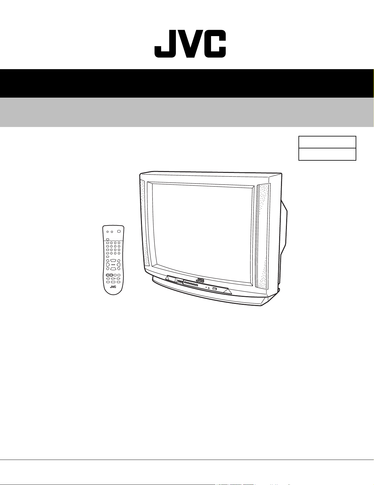
AV-20D304
SERVICE MANUAL
COLOR TELEVISION
BASIC CHASSIS
AV-20D304/SA
FE2
TABLE OF CONTENTS
1 PRECAUTIONS . . . . . . . . . . . . . . . . . . . . . . . . . . . . . . . . . . . . . . . . . . . . . . . . . . . . . . . . . . . . . . . . . . . . . . . 1-3
2 SPECIFIC SERVICE INSTRUCTIONS . . . . . . . . . . . . . . . . . . . . . . . . . . . . . . . . . . . . . . . . . . . . . . . . . . . . . . 1-4
3 ADJUSTMENT . . . . . . . . . . . . . . . . . . . . . . . . . . . . . . . . . . . . . . . . . . . . . . . . . . . . . . . . . . . . . . . . . . . . . . . 1-10
COPYRIGHT © 2003 VICTOR COMPANY OF JAPAN, LTD.
No.52103
2003/02
Page 2
AV-20D304
SPECIFICATION
Items Contents
Dimensions (W x H x D) 59.2cm x 45.6cm x 48.7cm (23-3/8” x 18” x 19-1/4”)
Mass 20.4kg (45 Ibs)
TV RF System CCIR(M)
Color Sound System NTSC, BTSC system (Multi Channel Sound)
TV Receiving Channels and Frequency
VL Band
VH Band
UHF Band
CATV Receiving Channels and Frequency
Low Band
High Band
Mid Band
Super Band
Hyper Band
Ultra Band
Sub Mid Band
TV/CATV Total Channel 180 channels
Intermediate Frequency
Video IF Carrier
Sound IF Carrier
Color Sub Carrier 3.58MHz
Power Input 120V AC, 60Hz
Power Consumption 75W
Picture Tube 20” (51cm) measured diagonally H : 40.6cm x V : 30.5cm
High Voltage 26.3kV±0.5kV (at zero beam current)
Speaker 5 x 9cm (2” x 3-1/2”) Oval type x 2
Audio Power Output 1.2W x 2
Antenna terminal (VHF/UHF) F-type connector, 75ohm
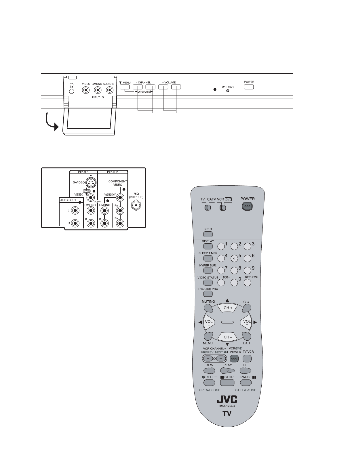
Video / Audio Input (1 / 2 / 3)
Video (1 / 3)
Audio (1 / 2 / 3)
S-Video (Input 1)
Component (Input 2)
Audio Output (Variable) More then 0~1550mV(rms) (+6dBs)
Headphone Jack 3.5mm mini jack x 1
Remote Control Unit RM-C1254G (AA battery x 2)
02ch~06ch : 54MHz~88MHz
07ch~13ch : 174MHz~216MHz
14ch~69ch : 470MHz~806MHz
54MHz~804MHz
02~06, A-8 by 02~06&01
07~13 by 07~13
A~1 by 14~22
J~W by 23~36
W+1~W+28 by 37~64
W+29~W+84 by 65~125
A8, A4~A1 by 01, 96~99
45.75MHz
41.25MHz (4.5MHz)
1V(p-p), 75ohm (RCA pin jack x 2)
500mV(rms) (-4dBs), high Impedance (RCA pin jack x 8)
Mini DIN 4pin x 1
Y : 1V(p-p) positive (negative sync provided, when terminated with 75ohm)
C : 0.286V(p-p) (burst signal when terminated with 75ohm)
RCA pin jack x 3
Y : 1V(p-p) positive (negative sync provided, when terminated with 75ohm)
Pb/Pr : 0.7V(p-p) 75ohm
low impedance (400Hz when modulated 100%) (RCA pin jack x )
Design & specifications are subject to change without notice.
1-2 (No.52103)
Page 3
SECTION 1
PRECAUTIONS
AV-20D304
1.1 SAFETY PRECAUTIONS
(1) The design of this product contains special hardware, many circuits
and components specially for safety purposes. For continued
protection, no changes should be made to the original design unless
authorized in writing by the manufacturer. Replacement parts must
be identical to those used in the original circuits. Service should be
performed by qualified personnel only.
(2) Alterations of the design or circuitry of the products should not be
made. Any design alterations or additions will void the manufacturer's
warranty and will further relieve the manufacturer of responsibility for
personal injury or property damage resulting therefrom.
(3) Many electrical and mechanical parts in the products have special
safety-related characteristics. These characteristics are often not
evident from visual inspection nor can the protection afforded by them
necessarily be obtained by using replacement components rated for
higher voltage, wattage, etc. Replacement parts that have these
special safety characteristics are identified in the parts list of Service
manual. Electrical components having such features are
identified by shading on the schematics and by ( ) on the parts
list in Service manual. The use of a substitute replacement which
does not have the same safety characteristics as the recommended
replacement part shown in the parts list of Service manual may cause
shock, fire, or other hazards.
(4) Use isolation transformer when hot chassis.
The chassis and any sub-chassis contained in some products are
connected to one side of the AC power line. An isolation transformer
of adequate capacity should be inserted between the product and the
AC power supply point while performing any service on some
products when the HOT chassis is exposed.
(5) Don't short between the LIVE side ground and ISOLATED
(NEUTRAL) side ground or EARTH side ground when repairing.
Some model's power circuit is partly different in the GND. The
difference of the GND is shown by the LIVE : ( ) side GND, the
ISOLATED(NEUTRAL) : ( ) side GND and EARTH : ( ) side GND.
Don't short between the LIVE side GND and ISOLATED(NEUTRAL)
side GND or EARTH side GND and never measure with a measuring
apparatus (oscilloscope etc.) the LIVE side GND and
ISOLATED(NEUTRAL) side GND or EARTH side GND at the same
time.
If above note will not be kept, a fuse or any parts will be broken.
(6) The high voltage applied to the picture tube must conform with that
specified in Service manual. Excessive high voltage can cause an
increase in X-Ray emission, arcing and possible component damage,
therefore operation under excessive high voltage conditions should
be kept to a minimum, or should be prevented. If severe arcing
occurs, remove the AC power immediately and determine the cause
by visual inspection (incorrect installation, cracked or melted high
voltage harness, poor soldering, etc.). To maintain the proper
minimum level of soft X-Ray emission, components in the high
voltage circuitry including the picture tube must be the exact
replacements or alternatives approved by the manufacturer of the
complete product.
(7) If any repair has been made to the chassis, it is recommended that
the B1 setting should be checked or adjusted (See ADJUSTMENT
OF B1 POWER SUPPLY).
(8) Do not check high voltage by drawing an arc. Use a high voltage
meter or a high voltage probe with a VTVM. Discharge the picture
tube before attempting meter connection, by connecting a clip lead to
the ground frame and connecting the other end of the lead through a
10kΩ 2W resistor to the anode button.
(9) When service is required, observe the original lead dress. Extra
precaution should be given to assure correct lead dress in the high
voltage circuit area. Where a short circuit has occurred, those
components that indicate evidence of overheating should be
replaced. Always use the manufacturer's replacement components.
(10) Isolation Check
(Safety for Electrical Shock Hazard)After re-assembling the
product, always perform an isolation check on the exposed metal
parts of the cabinet (antenna terminals, video/audio input and output
terminals, Control knobs, metal cabinet, screwheads, earphone jack,
control shafts, etc.) to be sure the product is safe to operate without
danger of electrical shock.
a) Dielectric Strength Test
The isolation between the AC primary circuit and all metal
parts exposed to the user, particularly any exposed metal part
having a return path to the chassis should withstand a voltage
of 1100V AC (r.m.s.) for a period of one second.
(. . . . Withstand a voltage of 1100V AC (r.m.s.) to an appliance
rated up to 120V, and 3000V AC (r.m.s.) to an appliance rated
200V or more, for a period of one second.)
This method of test requires test equipment not generally
found in the service trade.
b) Leakage Current Check
Plug the AC line cord directly into the AC outlet (do not use a
line isolation transformer during this check.). Using a "Leakage
Current Tester", measure the leakage current from each
exposed metal part of the cabinet, particularly any exposed
metal part having a return path to the chassis, to a known good
earth ground (water pipe, etc.). Any leakage current must not
exceed 0.5mA AC (r.m.s.). However, in tropical area, this must
not exceed 0.2mA AC (r.m.s).
• Alternate Check Method
Plug the AC line cord directly into the AC outlet (do not use
a line isolation transformer during this check.). Use an AC
voltmeter having 1000 ohms per volt or more sensitivity in
the following manner. Connect a 1500ohm 10W resistor
paralleled by a 0.15µF AC-type capacitor between an
exposed metal part and a known good earth ground (water
pipe, etc.). Measure the AC voltage across the resistor with
the AC voltmeter. Move the resistor connection to each
exposed metal part, particularly any exposed metal part
having a return path to the chassis, and measure the AC
voltage across the resistor. Now, reverse the plug in the AC
outlet and repeat each measurement. Any voltage
measured must not exceed 0.75V AC (r.m.s.). This
corresponds to 0.5mA AC (r.m.s.).
However, in tropical area, this must not exceed 0.3V AC
(r.m.s.). This corresponds to 0.2mA AC (r.m.s.).
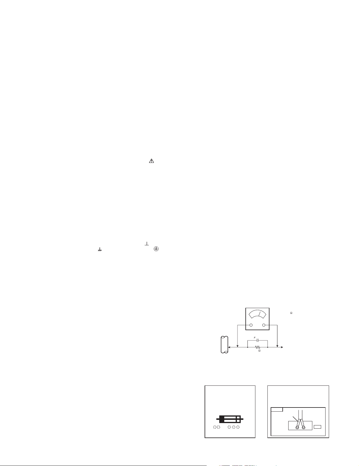
AC VOLTMETER
(HAVING 1000 /V,
OR MORE SENSITIVITY)
0.15 F AC-TYPE
PLACE THIS PROBE
GOOD EARTH GROUND
1500 10W
ON EACH EXPOSED
ME TAL PART
(11) High voltage hold down circuit check.
After repair of the high voltage hold down circuit, this circuit shall be
checked to operate correctly.
See item "How to check the high voltage hold down circuit".
This mark shows a fast
operating fuse, the
letters indicated below
show the rating.
A V
POWER CORD
REPLACEMENT WARNING.
Connecting the white line side of power
cord to "WHT" character side.
PWB
White line side
WHT
PW
(No.52103)1-3
Page 4
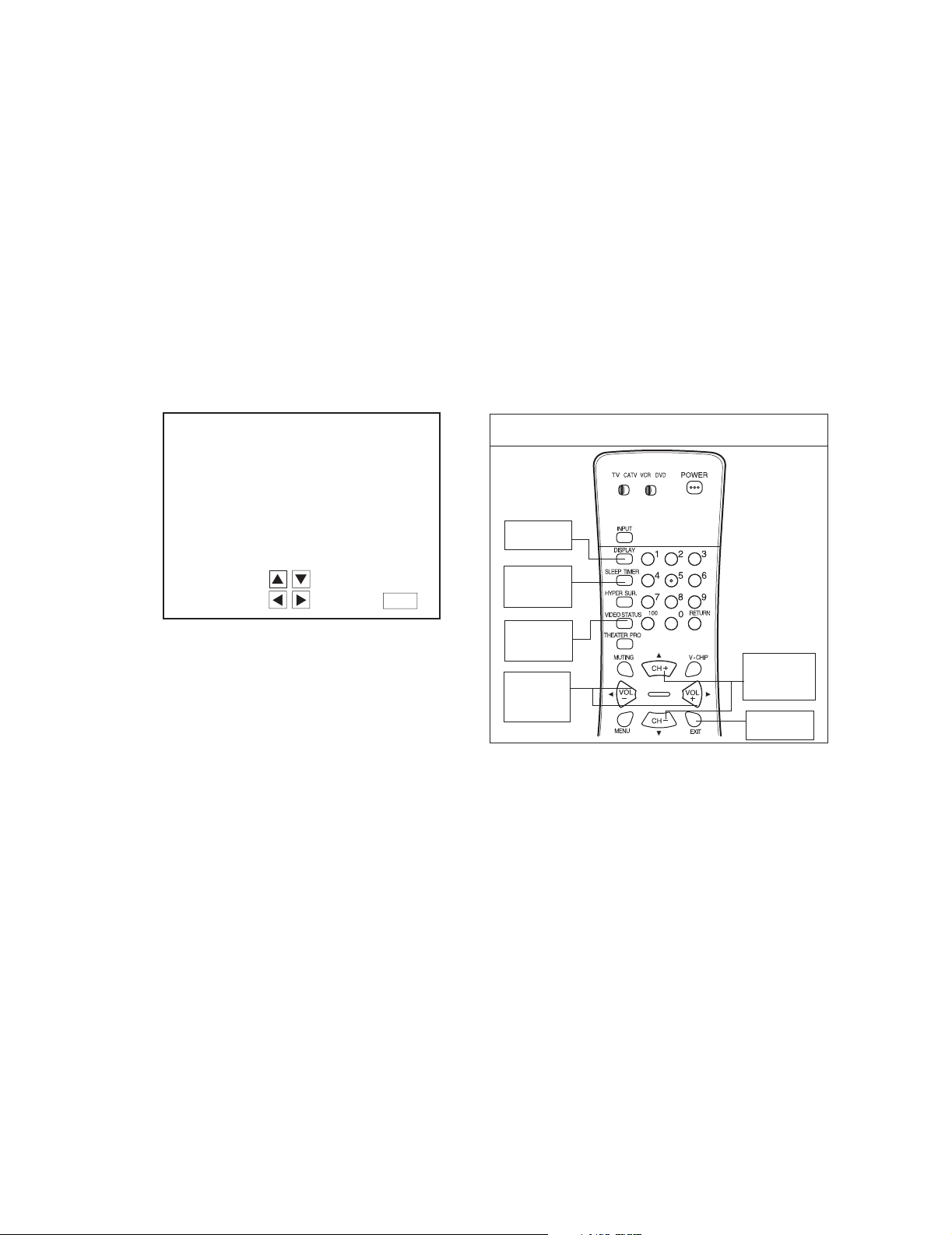
AV-20D304
2.1 FUNCTIONS
SECTION 2
SPECIFIC SERVICE INSTRUCTIONS
[FRONT PANEL]
MENU POWERCHANNEL
[REAR PANEL] [REMOTE CONTROL UNIT]
VOLUME
(RM-C1254G)
1-4 (No.52103)
Page 5

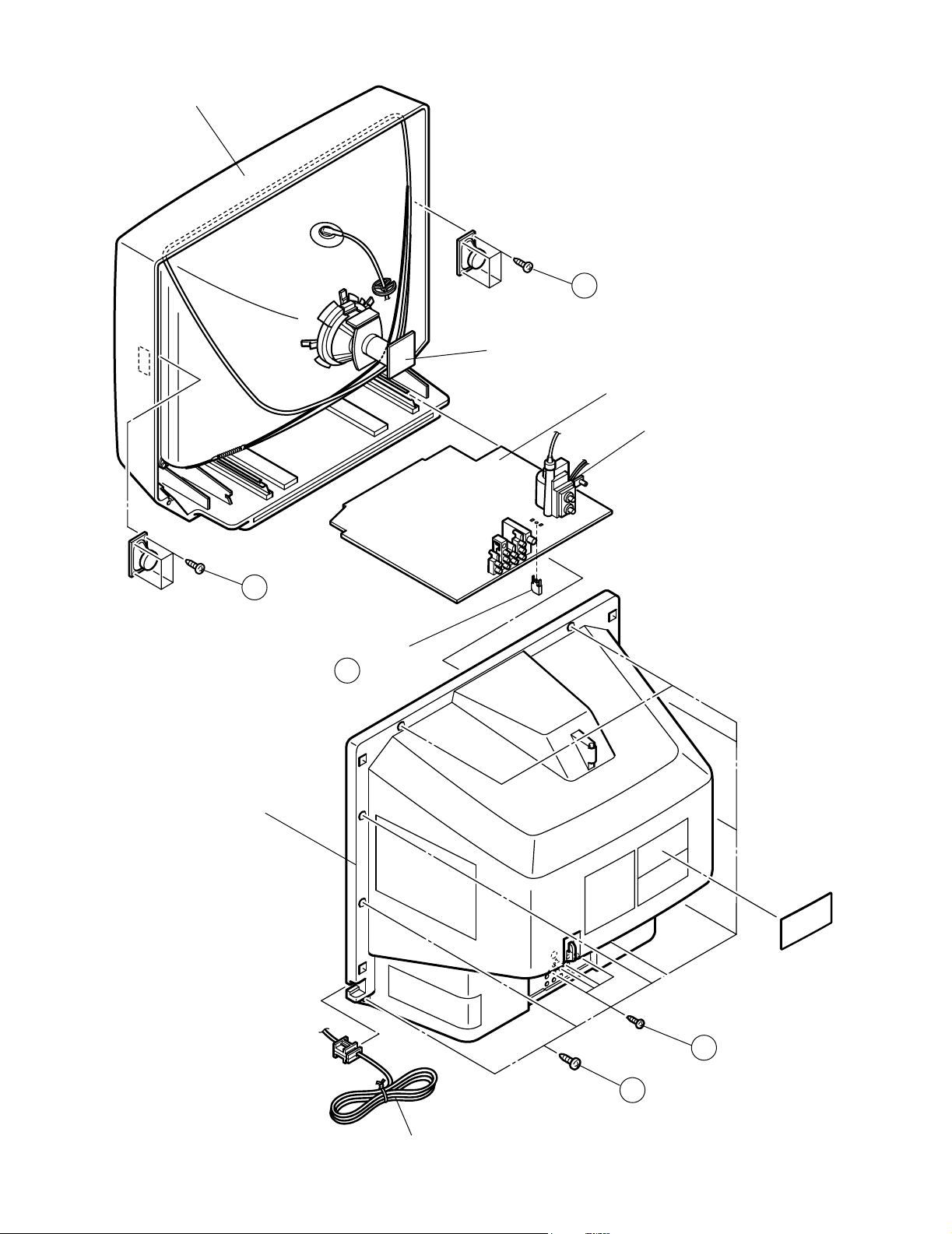
2.2 DISASSEMBLY PROCEDURE
AV-20D304
2.2.1 REMOVING THE REAR COVER
(1) Unplug the power plug.
(2) As shown in the Fig.1, remove the 9 screws [A].
(3) As shown in Fig.1, remove the 4 screws [B].
(4) Then remove the REAR COVER toward you.
2.2.2 REMOVING THE MAIN PWB
• Remove the REAR COVER.
(1) Raise the backside of the MAIN PWB, and remove the
PWB STOPPER [C] from the cabinet.
(2) Withdraw the MAIN PWB backward. (If necessary, remove
the wire clamp, connectors etc.)
2.2.3 REMOVING THE SPEAKER
• Remove the REAR COVER.
(1) As shown in Fig.1, remove the 4 screws [D], then remove
the speaker.
(2) Follow the same steps when remove the other hand
speaker.
NOTE:
When removing the 4 screws [D] of the speaker, remove the
lower side screw first, and then remove the upper one.
2.2.4 CHECKING THE PW BOARD
• Remove the REAR COVER.
(1) Pull out the MAIN CHASSIS (refer to REMOVING THE
MAIN PWB).
(2) Erect the MAIN CHASSIS vertically so that you can easily
check the backside of the PW Board.
CAUTION:
• When erecting the chassis, be careful so that there will be no
contacting with other PW Board.
• Before turning on power, make sure that the wire connector
is properly connected.
• When conducting a check with power supplied, be sure to
confirm that the CRT EARTH WIRE (BRAIDED ASS’Y) is
onnected to the CRT SOCKET PW board.
2.2.5 WIRE CLAMPING AND CABLE TYING
(1) Be sure to clamp the wire.
(2) Never remove the cable tie used for tying the wires
together. Should it be inadvertently removed, be sure to tie
the wires with a new cable tie.
(No.52103)1-5
Page 6
AV-20D304
FEONT CABINET
SPEAKER
D
CRT SOCKET PWB
MAIN PWB
HVT
SPEAKER
D
PWB STOPPER
C
REAR COVER
1-6 (No.52103)
B
A
POWER CORD
Fig.1
Page 7
2.3 MEMORY IC REPLACEMENT
2.3.1 MEMORY IC
This TV use memory IC.
In the memory IC, there are memorized data for correctly operating the video and deflection circuits.
When replacing the memory IC, be sure to use IC written with the initial values of data.
2.3.2 PROCEDURE FOR REPLACING MEMORY IC
(1) Power off
Switch the power off and unplug the power cord from the outlet.
(2) Replace IC
Be sure to use a memory IC written with the initial setting data.
(3) Power on
Connect the power cord to the outlet and switch the power on.
(4) Setting of receive channels
Set the receive channels. For setting, refer to the OPERATING INSTRUCTIONS.
(5) User settings
Check the user setting items according to “USER SETTING VALUES”, and if these are different, set the correct value.
(6) SERVICE MENU setting
Verify what to set in the SERVICE MENU, and set whatever is necessary. Refer to the ADJUSTMENT for setting.
AV-20D304
SERVICE MENU
1.V/C(S)
3.SOUND(A)
7.LOW LIGHT
9.VCO
11.I2C BUS
SELECT BY
OPERATE BY
2.DEF(D)
4.OTHERS(F)
8.HIGH LI GHT
EXIT BY
EX IT
KEY ASSIGNMENT OF REMOTE CONTROL UNIT
DISPLAY
SLEEP
TIMER
VIDEO
STATUS
CHANNEL
VOLUME
- / +
+ / -
EXIT
(No.52103)1-7
Page 8
AV-20D304
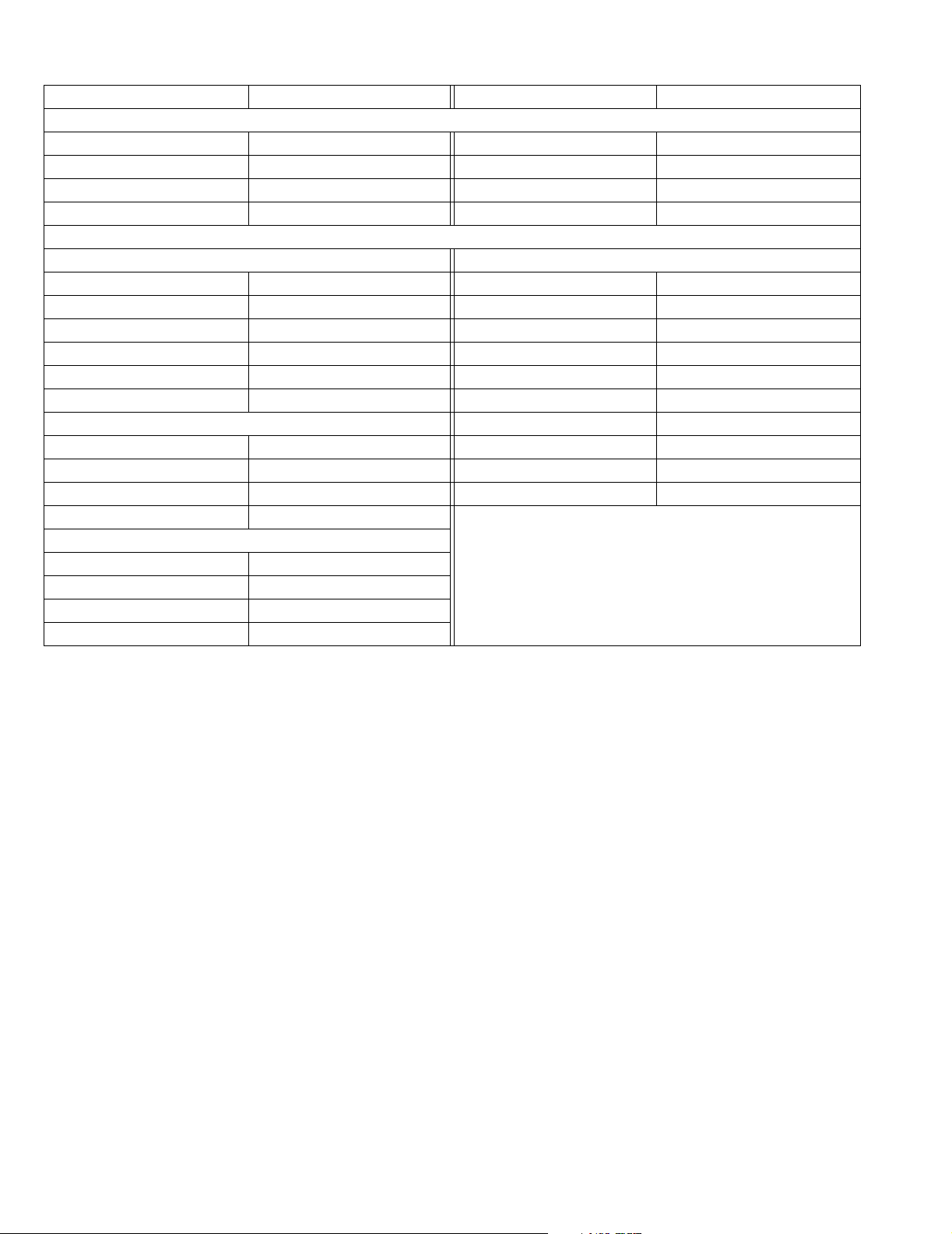
2.3.3 USER SETTING VALUES
Setting item Setting value Setting item Setting value
REMOTE CONTROL UNIT KEY
POWER OFF DISPLAY OFF
CHANNEL CH-02 VIDEO STATUS DYNAMIC
VOLUME 15 HYPER SURROUND OFF
TV/VIDEO TV
SETTING OF MENU
PICTURE MODE INITIAL SETUP MODE
TINT Center LANGUAGE ENG
COLOR Center FRONT PANELLOCK OFF
PICTURE +8 V2 COMPONENT-IN NO
BRIGHT Center AUTO SHUT OFF OFF
DETAIL +10 CLOSED CAPTION OFF
NOISE MUTING ON AUTO TUNER SET UP AIR
SOUND MODE CHANNEL SUMMARY Unnecessary to set
BASS Center V-CHIP OFF
TREBLE Center SET LOCK CODE (0000) Unnecessary to set
BALANCE Center XDS ID ON
MTS STEREO
CLOCK / TIMERS MODE
SET CLOCK MANUAL
TIME ZONE PACIFIC
D.S.T. OFF
ON / OFF TIMER OFF
1-8 (No.52103)
Page 9

2.4 REPLACEMENT OF CHIP COMPONENT
2.4.1 CAUTIONS
(1) Avoid heating for more than 3 seconds.
(2) Do not rub the electrodes and the resist parts of the pattern.
(3) When removing a chip part, melt the solder adequately.
(4) Do not reuse a chip part after removing it.
2.4.2 SOLDERING IRON
(1) Use a high insulation soldering iron with a thin pointed end of it.
(2) A 30w soldering iron is recommended for easily removing parts.
2.4.3 REPLACEMENT STEPS
1. How to remove Chip parts
[Resistors, capacitors, etc.]
(1) As shown in the figure, push the part with tweezers and
alternately melt the solder at each end.
AV-20D304
2. How to install Chip parts
[Resistors, capacitors, etc.]
(1) Apply solder to the pattern as indicated in the figure.
(2) Shift with the tweezers and remove the chip part.
[Transistors, diodes, variable resistors, etc.]
(1) Apply extra solder to each lead.
SOLDER
SOLDER
(2) As shown in the figure, push the part with tweezers and
alternately melt the solder at each lead. Shift and remove
the chip part.
(2) Grasp the chip part with tweezers and place it on the
solder. Then heat and melt the solder at both ends of the
chip part.
[Transistors, diodes, variable resistors, etc.]
(1) Apply solder to the pattern as indicated in the figure.
(2) Grasp the chip part with tweezers and place it on the
solder.
(3) First solder lead A as indicated in the figure.
A
B
C
Note :
After removing the part, remove remaining solder from the
pattern.
(4) Then solder leads B and C.
A
B
C
(No.52103)1-9
Page 10

AV-20D304
SECTION 3
ADJUSTMENT
3.1 ADJUSTMENT PREPARATION
(1) There are 2 ways of adjusting this TV : One is with the REMOTE CONTROL UNIT and the other is the conventional method
using adjustment parts and components.
(2) The adjustment using the REMOTE CONTROL UNIT is made on the basis of the initial setting values. The setting values which
adjust the screen to the optimum condition can be different from the initial setting values.
(3) Make sure that connection is correctly made AC to AC power source.
(4) Turn on the power of the TV and measuring instruments for warning up for at least 30 minutes before starting adjustments.
(5) If the receive or input signal is not specified, use the most appropriate signal for adjustment.
(6) Never touch the parts (such as variable resistors, transformers and condensers) not shown in the adjustment items of this service
adjustment.
(7) Preparation for adjustment. Unless otherwise specified in the adjustment items, preset the following functions with the REMOTE
CONTROL UNIT.
Item Preset value
PICTURE MODE (VSM) DYNAMIC
TINT, COLOR, PICTURE, BRIGHT, DETAIL CENTER
MTS STEREO
BASS TREBLE BALANCE CENTER
HYPER SURROUND OFF
3.2 MEASURING INSTRUMENT AND FIXTURES
(1) DC voltmeter (or digital voltmeter)
(2) Oscilloscope
(3) Signal generator (Pattern generator : NTSC)
(4) TV audio multiplex signal generator
(5) Remote control unit
1-10 (No.52103)
Page 11

3.3 ADJUSTMENT LOCATIONS
AV-20D304
FRONT
MAIN PWB
POWER
CRT SOCKET PWB
(Within MAIN PWB ASS'Y)
T
TP-E
(SOLDER SIDE)
VOL+ VOL- CH+ CH- MENU
TP-B
E1
TOP
CRT EARTH
(BRAIDED ASS'Y)
POWER
IC901
F901
IC702
MEMORY
IC201
T111
IC101
TUNER
IC421
S
HV
S401
HVT
U
X
B1
AV IN / OUT
UPPER : FOCUS
LOWER : SCREEN
Fig.1
(No.52103)1-11
Page 12

AV-20D304
3.4 BASIC OPERATION OF SERVICE MENU
3.4.1 TOOL OF SERVICE MENU OPERATION
Operate the SERVICE MENU with the REMOTE CONTROL UNIT.
3.4.2 SERVICE MENU ITEMS
With the SERVICE MENU, various adjustments can be made, and they are broadly classified in the following items of settings.
(1) V/C (S) This mode adjusts the VIDEO and CHROMA control circuit.
(2) DEF (D) This mode adjusts the DEFLECTION control circuit.
(3) SOUND (A) This mode adjusts the SOUND control circuit.
(4) OTHERS (F) This mode adjusts the display setting and the other settings (Do not change the values).
(7) LOW LIGHT This mode adjusts the WHITE BALANCE (LOW LIGHT) control circuit.
(8) HIGH LIGHT This mode adjusts the WHITE BALANCE (HIGH LIGHT) control circuit.
(9) VCO This mode adjusts the VCO control circuit.
2
(11) I2C BUS This mode adjusts the I
C BUS control circuit (They are fixed).
1-12 (No.52103)
Page 13

3.4.3 BASIC OPERATION IN SERVICE MENU
3.4.3.1 HOW TO ENTER THE SERVICE MENU
(1) Press the [SLEEP TIMER] key and set the SLEEP TIMER
for "0 MIN".
Then press the [DISPLAY] key and [VIDEO STATUS] key
of the remote control unit at the same time to enter the
SERVICE MENU screen.
3.4.3.2 SUB MENU SCREEN SELECTION
Press [VOLUME (-/+)] keys of the remote control unit, and select
the SUB MENU SCREEN from SERVICE MENU.
In SERVICE MENU, press the [CHANNEL (-/+)] key to select any
of the SUB MENU items. The letters of the selected items are
displayed in yellow.
1.V/C(S) 2.DEF(D)
3.SOUND(A) 4.OTHERS(F)
7.LOW LIGHT 8.HIGH LIGHT
9.VCO
11.I2C BUS
SERVICE MENU
1.V/C(S)
3.SOUND(A)
2.DEF(D)
4.OTHERS(F)
7.LOW LIGHT
8.HIGH LI GHT
9.VCO
11.I2C BUS
SELECT BY
OPERATE BY
EXIT BY
EX IT
Fig.1
KEY ASSIGNMENT OF REMOTE CONTROL UNIT
DISPLAY
SLEEP
TIMER
AV-20D304
VIDEO
STATUS
VOLUME
- / +
Fig.2
3.4.3.3 SETTING METHOD [1.V/C(S) ADJUSTMENT MODE]
For example, adjust the 1.V/C(S) by using the remote control unit.
1) Press the [CHANNEL (-/+)] keys to select the one of adjustment mode from S01 BRIGHT to S21 AGC ADJ.
2) Press the [VOLUME (-/+)] keys to change the adjustment value. The setting value will be stored automatically when release
the REMOTE CONTROL UNIT keys.
It can adjust the items from 1.V/C(S) to 3.SOUND(A) in the same procedure.
[7.LOW LIGHT, 8.HIGH LIGHT AND 9.VCO ADJUSTMENT MODE]
Since the key operation in this mode is peculiar, please refer to the clause of the "ADJUSTMENT PROCEDURE".
[4.OTHERS AND 11.I2C BUS ADJUSTMENT MODE]
These are no requirement for adjustment. Setting only. Don't change these values.
3.4.3.4 RELEASE OF SERVICE MENU
When adjustment is completed, press the [EXIT] key twice. Then return to the normal screen.
CHANNEL
+ / -
EXIT
(No.52103)1-13
Page 14

AV-20D304
3.4.4 SERVICE MENU FLOW CHART
SERVICE MENU (MAIN MENU)
SERVICE MENU
1.V/C(S) 2.DEF(D)
3.SOUND(A) 4.OTHERS(F)
7.LOW LIGHT 8.HIGH LIGHT
9.VCO
11.12C BUS
SELECT BY
OPERATE BY EXIT BY
EXIT
1.V/C(S)
RF 4 : 3 STD LOW
S01 BRIGHT
***
2.DEF(D)
RF 4 : 3 STD LOW
D01 V FREQ
3.SOUND(A)
A01 IN LEVEL
***
7.LOW LIGHT
BRIGHT
***
***
***
8.HIGH LIGHT
******
9.VCO
TOO HIGH GOOD TOO LOW
SYNC: YES
AFC ON
FINE 0
Do not adjust
1-14 (No.52103)
4.OTHERS(F)
F01 OSD POSI
11.I2C BUS
Do not adjust
***
Fig.3
I2C BUS ON
Page 15

AV-20D304
3.5 INITIAL SETTING VALUE OF SERVICE MENU
(1) Adjustment of the SERVICE MENU is made on the basis of the initial setting values. However, the new setting values which
displays on the screen in its optimum condition may differ from the initial setting value.
(2) Do not change the initial setting values of the items not listed in "ADJUSTMENT PROCEDURE".
(3) "---" is impossible to adjust.
3.5.1 [1.V / C]
Initial setting value
No. Setting item Variable range
STANDARD THEATER STANDARD THEATER STANDARD THEATER
S01 BRIGHT 0~127 64 --- --- --- --- ---
S02 PICTURE 0~127 65 --- --- --- --- ---
S03 COLOR 0~127 41 --- --- --- 47 ---
S04 TINT 0~127 63 --- --- --- 64 ---
S05 DETAIL 0~63 30 --- 35 --- 40 ---
S06 BRIGHT +- -128~+127 --- 0 1 --- 1 ---
S07 PICT+- -128~+127 --- -15 0 --- 0 ---
S08 COLOR +- -128~+127 --- -3 0 --- --- ---
S09 TINT+- -128~+127 --- -6 -4 --- --- ---
S10 DETAIL+- -128~+127 --- 3 --- --- --- ---
RF EXTERNAL (SV / CV) COMPONENT
Initial setting value
No. Setting item Variable range
S11 R CUT OFF 0~255 30 --- --- --- --- --- --- ---
S12 G CUT OFF 0~255 30 --- --- --- --- --- --- ---
S13 B CUT OFF 0~255 30 --- --- --- --- --- --- ---
S14 R DRIVE 0~127 64 --- --- --- --- --- --- ---
S15 B DRIVE 0~127 64 --- --- --- --- --- --- ---
S16 R CUT+- -128~+127 --- 0 0 0 0 --- --- ---
S17 G CUT+- -128~+127 --- 0 0 0 0 --- --- ---
S18 B CUT+- -128~+127 --- 0 0 0 0 --- --- ---
S19 R DRV+- -128~+127 --- 5 13 7 0 --- --- ---
S20 B DRV+- -128~+127 --- 6 -25 -9 0 --- --- ---
No. Setting item Variable range Initial setting value
S21 AGC ADJUST 0~127 64
STANDARD THEATER STANDARD THEATER
LOW HIGH LOW HIGH LOW HIGH LOW HIGH
RF/EXT (SV / CV) COMPONENT
(No.52103)1-15
Page 16

AV-20D304
3.5.2 [2.DEF]
No. Setting item Variable range
D01 AFC GAIN 0~3 0 2
D02 H POSI 0~31 13 13
D03 V SIZE 0~125 65 65
D04 V S CORR 0~15 0 0
D05 V LIN 0~15 8 8
D06 H SIZE 0~63 32 32
D07 WVMT TOP 0~3 0 0
D08 WVMT BTM 0~3 0 0
D09 EWCR TOP 0~31 16 16
D10 EWCR BTM 0~31 16 16
D11 EW PARA 0~63 26 26
D12 BLANK SW 0~1 0 0
3.5.3 [3.SOUND MODE]
No. Setting item Variable range Initial setting value
A01 IN LEVEL 0~63 36
A02 FH MON 0~1 0
A03 ST VCO 0~63 43
A04 PIL CAN 0~1 0
A05 FILTER 0~63 35
A06 LOW SEP 0~63 8
A07 HI SEP 0~63 26
A08 5FH MON 0~1 0
A09 SAP VCO 0~63 44
Initial setting value
RF EXTERNAL (SV / CV)
3.5.4 [4.OTHERS]
No. Setting item Variable range Initial setting value
F01 OSD POSI 0~255 28
F02 OSD PREQ 0~255 85
F03 CCD POSI 0~63 47
F04 CCD FREQ 0~255 94
F05 CCD CONT 0~63 11
F06 PUR CONT 0~255 62
F07 VNR CHK 0~255 3
F08 VCSN TM 0~255 5
F09 CCD PCHK 0~1 1
3.5.5 [7.LOW LIGHT MODE]
No. Setting item Variable range Initial setting value
1 RED 0~255 30
2 GREEN 0~255 30
3 BLUE 0~255 30
3.5.6 [8.HIGH LIGHT MODE]
No. Setting item Variable range Initial setting value
1 RED 0~255 64
2 BLUE 0~255 64
1-16 (No.52103)
Page 17

3.6 ADJUSTMENTS PROCEDURE
3.6.1 CHECK ITEM
Item
B1 POWER
SUPPLY
Measuring
instrument
DC voltmeter
Signal
generator
B1 Connector
TP-91
TP-E
[MAIN PWB]
3.6.2 VCO
Item
Measuring
instrument
IF VCO Remote
control unit
TOO HIGH GOOD TOO LOW
SYNC: YES
AFC ON
FINE 0
Test point Adjustment part Description
(1) Receive the black and white signal. (color off)
(2) Connect the DC voltmeter to TP-91 (B1 connector 1
pin) and TP-E (B1 connector 3 pin).
(3) Confirm that the voltage is DC134V±2V.
Test point Adjustment part Description
[9.VCO]
• It must not adjust without inputting the RF signal.
(1) Receive a broadcast.
CW transf. (T111)
[MAIN PWB]
(2) Select 9.VCO in the SERVICE MENU.
(3) Confirm that the color change from "TOO HIGH" to
"TOO LOW" by CW transf. on MAIN PWB, and
check the "SYNC : YES".
(4) Adjust CW transf. until "GOOD" letters turns green.
And then confirm that the "SYNC : YES" again.
Adjustment can be done in this statement.
(5) Push the [EXIT] key to exit the [9.VCO] mode.
AV-20D304
3.6.3 RF AGC
Item
Measuring
instrument
RF AGC Signal
generator
Remote
control unit
No
S21
Setting item
AGC ADJ 0~127
Test point Adjustment part Description
[1.V/C(S)]
S21 : AGC ADJ
(1) Receive a black and white signal (colour off).
(2) Select <S21>(AGC ADJ) of the 1.V/C(S).
(3) Press the [MUTING] key and turn the picture color
off.
(4) With the [VOLUME (-)] key to get the noise in the
screen picture (zero side of setting value).
(5) Press the [VOLUME (+)] key several times and step
when noise disappears from the screen (at that time,
Variable
range
Initial setting
value
not to increase the value too much).
(6) Change to other channels and make sure that there
is no irregularity.
80
(7) Press the [MUTING] key and get color out.
(No.52103)1-17
Page 18

AV-20D304
3.6.4 FOCUS
Item
FOCUS Signal
generator
3.6.5 DEFLECTION CIRCUIT
Measuring
instrument
Test point Adjustment part Description
FOCUS VR
[In HVT]
(1) Receive the crosshatch signal.
(2) While looking at the screen, adjust the FOCUS VR
to the vertical and horizontal lines will be clear and in
fine detail.
(3) Make sure that the picture is in focus even when the
screen gets darkened.
Item
V. SIZE &
V. CENTER
Measuring
instrument
Signal
generator
Remote
control unit
Screen
size
(90%)
No
S03
Setting item
V SIZE 0~125
H. CENTER Signal
generator
Remote
control unit
Test point Adjustment part Description
[2.DEF(D)]
D03 : V SIZE
(1) Receive the crosshatch signal.
(2) Select the <D03>(V SIZE).
(3) Adjust the <D03> so that the vertical screen size
V. CENTER SW(S401)
[MAIN PWB]
becomes 90%.
(4) Adjust the V’ CENTER SW to agree the vertical cen-
ter with display center.
Picture
size
(100%)
Variable
range
Initial setting
value
65
[2.DEF(D)]
D02 : H POSI
(1) Receive the crosshatch signal.
(2) Select <D02>(H POSI).
(3) Adjust the <D02> so that left width and right width of
the crosshatch screen becomes equal.
No
D02
1-18 (No.52103)
Setting item
H POSI 0~31
Variable
range
Initial setting
value
10
Page 19

3.6.6 VIDEO CIRCUIT
Item
WHITE
BALANCE
Measuring
instrument
Signal
generator
(LOW LIGHT)
Remote
control unit
KEY ASSIGNMENT OF REMOTE CONTROL UNIT
H LINE ON
Test point Adjustment part Description
[7.LOW LIGHT]
(1) Receive the black and white signal ( color off ).
(2) Select the 7.LOW LIGHT in the SERVICE MENU.
[1.V/C(S)]
S11 : R CUTOFF
S12 : G CUTOFF
S13 : B CUTOFF
S01 : BRIGHT
(3) Set the initial setting value of <S11>(R CUTOFF),
<S12>(G CUTOFF), <S13>(B CUTOFF) and
<S01>(BRIGHT).
(4) Display a single horizontal line by pressing the [1]
key.
(5) Turn the SCREEN VR all the way to the left.
SCREEN VR
[ in HVT]
(6) Turn the SCREEN VR gradually to the right from the
left until either one of the red, blue or green color
appears faintly.
(7) Adjust the two colors which did not appear until the
single horizontal line that is displayed becomes
white using the [4] to [9] keys.
(8) Turn the SCREEN VR until the single horizontal line
R CUTOFF
H LINE OFF
G CUTOFF
EXIT
B CUTOFF
B CUTOFF
is displayed faintly.
(9) Press the [2] key to cancel the single horizontal line
mode.
(10) Adjust the <S01> level to become the black
component shines white slightly by [VOLUME] key.
(11) Confirm that whether the color ingredient of R,G,or B
is visible to the black component, which shines white
slightly.
(12) When the color ingredient can be seen, two colors
other than a visible color is adjusted, and it is made
G CUTOFF
R CUTOFF
to look white.
(13) Return the value of <S01> to initial setting value.
AV-20D304
No
S11
S12 G CUT OFF 0~255 30
S13 B CUT OFF 0~255 30
S01 BRIGHT 0~127 64
Setting item
R CUT OFF 0~255
Variable
range
Initial setting
value
30
NOTE:
If the [3] key is pressed, it can escape from WHITE
BALANCE adjustment mode.
(No.52103)1-19
Page 20

AV-20D304
Item
WHITE
BALANCE
(HIGH LIGHT)
Measuring
instrument
Signal
Test point Adjustment part Description
[8.HIGH LIGHT]
generator
[1.V/C(S)]
Remote
control unit
KEY ASSIGNMENT OF REMOTE CONTROL UNIT
R DRIVE
R DRIVE
S14 : R DRIVE
S15 : B DRIVE
EXIT
B DRIVE
B DRIVE
(1) Receive the black and white signal ( color off ).
(2) Select the 8.HIGH LIGHT in the SERVICE MENU.
(3) Set the initial setting value of <S14>(R DRIVE) and
<S15>(B DRIVE) with the [4], [6], [7] and [9] keys.
(4) Adjust the screen until it becomes white by using the
[4], [6], [7] and [9] keys.
NOTE:
If the [3] key is pressed, it can escape from WHITE
BALANCE adjustment mode.
No
S14
S15 G DRIVE 0~127 64
Setting item
R DRIVE 0~127
SUB BRIGHT Remote
control unit
No
S01
SUB
CONTRAST
No
S02
Setting item
BRIGHT 0~127
Remote
control unit
Setting item
PICTURE 0~127
Variable
range
Variable
range
Variable
range
Initial setting
value
64
[1.V/C(S)]
S01 : BRIGHT
Initial setting
value
64
[1.V/C(S)]
S02 : PICTURE
Initial setting
value
65
(1) Receive the broadcast.
(2) Select <S01>(BRIGHT) of the 1.V/C(S).
(3) Set the initial setting value of the <S01> with the
[VOLUME (-/+)] key.
(4) If the brightness is not the best with the initial setting
value, make fine adjustment of the <S01> until you
get the optimum brightness.
(1) Receive the broadcast.
(2) Select <S02>(PICTURE) of the 1.V/C(S).
(3) Set the initial setting value of the <S02> with the
[VOLUME (-/+)] key.
(4) If the contrast is not the best with the initial setting
value, make fine adjustment of the <S02> until you
get the optimum contrast.
1-20 (No.52103)
Page 21

AV-20D304
Item
Measuring
instrument
SUB COLOR Signal
generator
Oscilloscope
Remote
control unit
No
Setting item
W
Test point Adjustment part Description
TP-B
TP-E
[CRT SOCKET
PWB]
Y
G
C
R
M
Variable
range
[1.V/C(S)]
S03 : COLOR
[ Method of adjustment without measuring instrument ]
(1) Receive the broadcast.
(2) Select <S03>(COLOR) of the 1.V/C(S).
(3) Set the initial setting value of the <S03> with the
[VOLUME (-/+)] key.
(4) If the color is not the best with the Initial setting
value, make fine adjustment of the <S03> until you
get the optimum color.
[ Method of adjustment using measuring instrument ]
(1) Receive the full field color bar signal (75% white).
(2) Select <S03>(COLOR) of the 1.V/C(S).
(3) Set the initial setting value of the <S03> with the
[VOLUME (-/+)] key.
(A)
(-)
0V
B
(+)
Initial setting
value
(4) Connect the oscilloscope between TP-B and TP-E.
(5) Adjust <S03> and bring the value of (A) in the
illustration to +10V.
S03
COLOR 0~127
SUB TINT Signal
generator
Oscilloscope
Remote
control unit
W
TP-B
TP-E
[CRT SOCKET
PWB]
Y
G
C
M
41
[1.V/C(S)]
S04 : TINT
[ Method of adjustment without measuring instrument ]
(1) Receive the broadcast.
(2) Select <S04>(TINT) of the 1.V/C.
(3) Set the initial setting value of the <S04> with the
[VOLUME (-/+)] key.
(4) If the tint is not the best with the initial setting value,
make fine adjustment of the <S04> until you get the
optimum tint.
[ Method of adjustment using measuring instrument ]
(1) Receive the full field color bar signal (75% white).
(2) Select <S04>(TINT) of the 1.V/C.
R
(B)
(-)
0V
B
(+)
(3) Set the initial setting value of the <S04> with the
[VOLUME (-/+)] key.
(4) Connect the oscilloscope between TP-B and TP-E.
(5) Adjust <S04> and bring the value of (B) in the
illustration to +14V.
No
S04
Setting item
TINT 0~127
Variable
range
Initial setting
value
63
(No.52103)1-21
Page 22

AV-20D304
3.6.7 MTS CIRCUIT
Item
MTS INPUT
LEVEL
Measuring
instrument
Remote
control unit
Test point Adjustment part Description
[3.SOUND(A)]
A01 : IN LEVEL
(1) Select the <A01>(IN LEVEL) of the 3.SOUND.
(2) Verify that the <A01> is set at its initial setting value.
No
A01
MTS
SEPARATION
1 cycle
Setting item
IN LEVEL 0~63
TV audio
multiplex
Signal
generator
Oscilloscope
Remote
control unit
L-Channel
signal waveform
Variable
range
R OUT
L OUT
[AUDIO OUT]
R-Channel
crosstalk portion
Minimum
Initial setting
value
036
[3.SOUND(A)]
A06 : LOW SEP
A07 : HI SEP
(1) Input the stereo L signal (300Hz) from the TV audio
multiplex signal generator to the antenna terminal.
(2) Connect an oscilloscope to R OUT pin of the AUDIO
OUT, and display one cycle portion of the 300Hz
signal.
(3) Select the <A06>(LOW SEP) of the SOUND MODE.
(4) Set the initial setting value of the <A06> with the
[VOLUME (-/+)] key.Adjust the <A06> so that the
stroke element of the 300Hz signal will become
minimum.
(5) Change the connection of the oscilloscope to L OUT
pin of the AUDIO OUT, and enlarge the voltage axis.
(6) Change the signal to 3kHz, and similarly adjust the
<A07>(HI SEP).
No
A06
A07 HI SEP 0~63 026
Setting item
LOW SEP 0~63
Variable
range
Initial setting
value
008
1-22 (No.52103)
Page 23

3.6.8 PURITY AND CONVERGENCE
PURITY ADJUSTMENT
(1) Demagnetize CRT with the demagnetizer.
(2) Loosen the retainer screw of the deflection yoke.
(3) Remove the wedges.
(4) Input a green raster signal from the signal generator, and
turn the screen to green raster.
(5) Move the deflection yoke backward.
(6) Bring the long lug of the purity magnets on the short lug and
position them horizontally. (Fig.2)
WEDGE
CRT
P/C MAGNETS
P : PURITY MAGNET
4 : 4 POLES (convergence magnets)
6 : 6 POLES (convergence magnets)
DEFLECTION
YOKE
㪧
㪋㪍
P / C
MAGNETS
Fig.1
AV-20D304
(7) Adjust the gap between two lugs so that the GREEN
RASTER will come into the center of the screen. (Fig.3)
(8) Move the deflection yoke forward, and fix the position of the
deflection yoke so that the whole screen will become green.
(9) Insert the wedge to the top side of the deflection yoke so that
it will not move.
(10) Input a crosshatch signal.
(11) Verify that the screen is horizontal.
(12) Input red and blue raster signals, and make sure that purity
is properly adjusted.
Long lug
Short lug
(FRONT VIEW)
PURITY MAGNETS
Bring the long lug over the short lug
and position them horizontally.
Fig.2
GREEN RASTER
CENTER
Fig.3
(No.52103)1-23
Page 24

AV-20D304
STATIC CONVERGENCE ADJUSTMENT
(1) Input a crosshatch signal.
(2) Using 4-pole convergence magnets, overlap the red and
blue lines in the center of the screen (Fig.1) and turn them
to magenta (red/blue).
(3) Using 6-pole convergence magnets, overlap the magenta
(red/blue) and green lines in the center of the screen and
turn them to white.
(4) Repeat 2 and 3 above, and make best convergence.
(FRONT VIEW)
Fig.1
DYNAMIC CONVERGENCE ADJUSTMENT
(1) Move the deflection yoke up and down and overlap the lines
in the periphery. (Fig. 2)
(2) Move the deflection yoke left to right and overlap the lines in
the periphery. (Fig. 3)
(3) Repeat 1 and 2 above, and make best convergence.
• After adjustment, fix the wedge at the original position. Fasten
the retainer screw of the deflection yoke. Fix the 6 magnets with
glue.
(FRONT VIEW)
BLUE
GREEN
RED
(FRONT VIEW)
GREEN
RED
RED
BLUE
BLUE
GREEN
GREEN RED
BLUE
Fig.2
BLUE
GREEN
RED
RED
GREEN
BLUE
RED
GREEN
BLUE
1-24 (No.52103)
Fig.3
BLUE
GREEN
RED
Page 25

3.6.9 HOW TO CHECK THE HIGH VOLTAGE HOLD DOWN CIRCUIT
3.6.9.1 HIGH VOLTAGE HOLD DOWN CIRCUIT
After repairing the high voltage hold down circuit shown in Fig.1.
This circuit shall be checked to operate correctly.
3.6.9.2 CHECKING OF THE HIGH VOLTAGE HOLD DOWN CIRCUIT
(1) Turn the power switch to on.
(2) As shown in Fig. 1, set the resistor between [X] connector [1] and [3].
(3) Make sure that the screen picture disappears.
(4) Temporarily unplug the power plug.
(5) Remove the resistor replaced [X] connector [1] and [3].
(6) Again plug the power plug, make sure that the normal picture is displayed on the screen.
RESISTOR
18.00 k
±1%
AV-20D304
POWER
ON OFF
Fig.1
CONNECTOR
X3 2 1
HEATER
T521
4
(No.52103)1-25
Page 26

AV-20D304
JVC SERVICE & ENGINEERING COMPANY OF AMERICA
DIVISION OF JVC AMERICAS CORP.
www.jvcservice.com(US Only)
JVC CANADA INC.
Head office : 21 Finchdene Square Scarborough, Ontario M1X 1A7 (416)293-1311
(No.52103)
Printed in Japan
200302WPC
 Loading...