

Page 1

52111200303
POWER
DISPLAY
INPUT
100+
RETURN+
MUTING
MENU
CHIP
EXIT
CHANNEL
VCR CONTROL
POWER
TV/VCR
REC
STOP
PAUSE
PLAYFFFF
REW
SLEEP
TIMER
VIDEO
STATUS
RM-C205
AV-20420
AV-20421
SERVICE MANUAL
COLOR TELEVISION
BASIC CHASSIS
AV-20420/SA,
FV5
AV-20421/SA
SLEEP
VIDEO
POWER
TIMER
STATUS
DISPLAY
INPUT
1
3
2
4
6
5
7
9
8
100+
RETURN+
0
MUTING
V—CHIP
+
CH
VOL
VOL
+
CH
MENU
EXIT
VCR CONTROL
CHANNEL
POWER
TV/VCR
PLAY
REW
PAUSE
REC
STOP
RM-C205
TABLE OF CONTENTS
1 PRECAUTIONS . . . . . . . . . . . . . . . . . . . . . . . . . . . . . . . . . . . . . . . . . . . . . . . . . . . . . . . . . . . . . . . . . . . . . . . 1-3
2 SPECIFIC SERVICE INSTRUCTIONS. . . . . . . . . . . . . . . . . . . . . . . . . . . . . . . . . . . . . . . . . . . . . . . . . . . . . . 1-4
3 ADJUSTMENT . . . . . . . . . . . . . . . . . . . . . . . . . . . . . . . . . . . . . . . . . . . . . . . . . . . . . . . . . . . . . . . . . . . . . . . 1-12
4 TROUBLE SHOOTING. . . . . . . . . . . . . . . . . . . . . . . . . . . . . . . . . . . . . . . . . . . . . . . . . . . . . . . . . . . . . . . . . 1-30
COPYRIGHT © 2003 VICTOR COMPANY OF JAPAN, LTD.
No.52111
2003/03
Page 2
AV-20420
AV-20421
SPECIFICATION
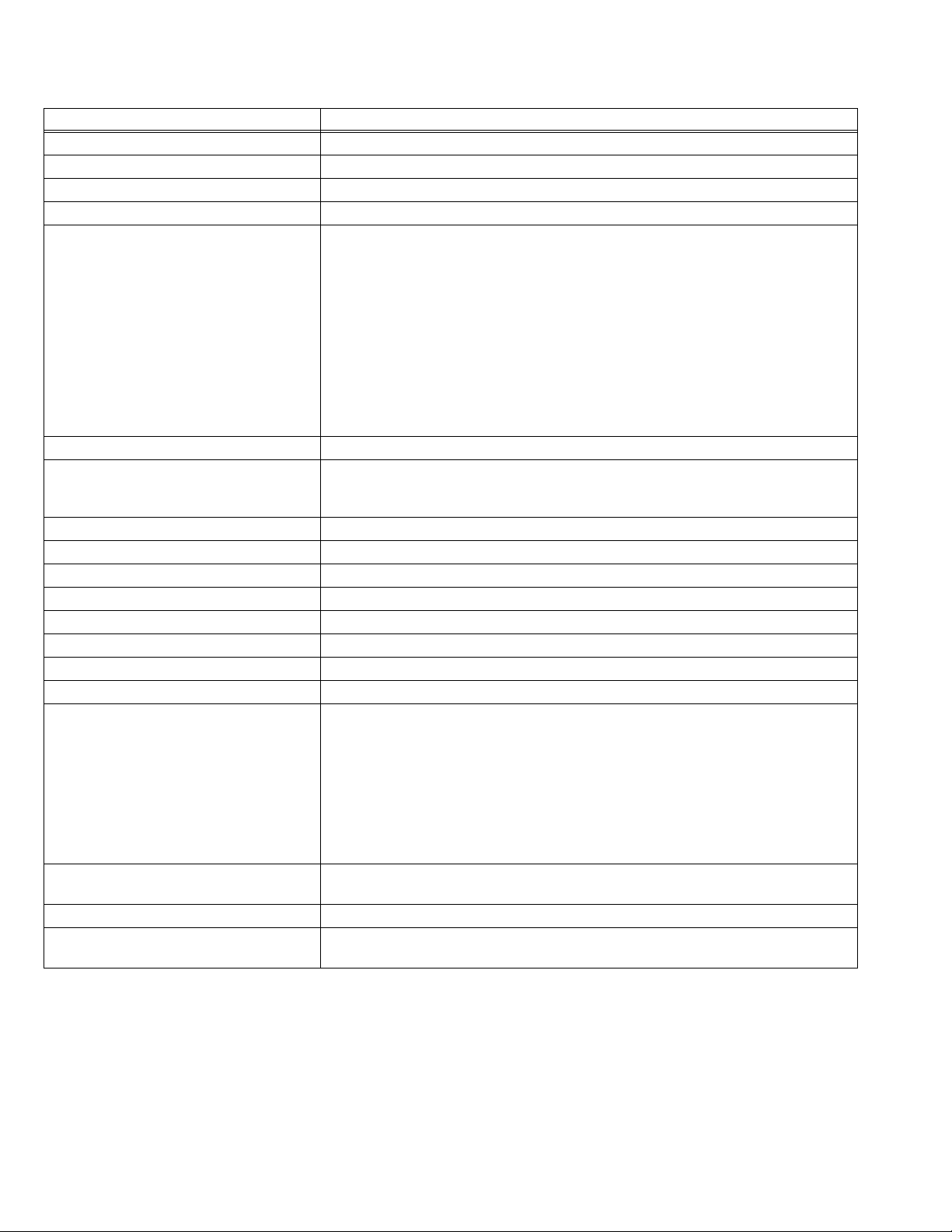
Items Contents
Dimensions (W x H x D) 50.3cm x 45.2cm x 49.3cm (19-7/8” x 17-7/8” x 19-1/2”)
Mass 19.9 kg (43.8 Ibs)
TV RF System CCIR(M)
Color Sound System NTSC, BTSC system (Multi Channel Sound)
TV Receiving Channels and Frequency
VHF LOW
VHF HIGH
TV/CATV Total Channel 180 channels
Intermediate Frequency
Video IF Carrier
Sound IF Carrier
Color Sub Carrier 3.58MHz
Power Input AC 120V, 60Hz
Power Consumption 87W
Picture Tube 20” (51cm) measured diagonally H : 40.6cm x V : 30.5cm
High Voltage 26.5kV±1kV (at zero beam current)
Speaker 5 x 9cm (2” x 3-1/2”) Oval type x 2
Audio Power Output 1W+1W
Antenna Terminal (VHF/UHF) F-type connector, 75ohm
Video / Audio Input (1 / 2 / 3)
Video (1 / 3)
Audio (1 / 2 / 3)
S-Video (1)
Component (2)
Audio Output (Variable) More then 0~1550mV(rms) (+6dBs)
Headphone Jack 3.5mm mini jack x 1
Remote Control Unit RM-C205 (AA/R6/UM-3 battery x 2) [AV-20420]
02ch~06ch : 54MHz~88MHz
07ch~13ch : 174MHz~216MHz
UHF
14ch~69ch : 470MHz~806MHz
CATV
54MHz~804MHz
Low Band : 02~06, A-8 by 02~06&01
High Band : 07~13 by 07~13
Mid Band : A~1 by 14~22
Super Band : J~W by 23~36
Hyper Band : W+1~W+28 by 37~64
Ultra Band : W+29~W+84 by 65~125
Sub Mid Band : A8, A4~A1 by 01, 96~99
45.75MHz
41.25MHz (4.5MHz)
1V(p-p), 75ohm (RCA pin jack x 2)
500mV(rms) (-4dBs), high Impedance (RCA pin jack x 8)
Mini DIN 4pin x 1
Y : 1V(p-p) positive (negative sync provided, when terminated with 75ohm)
C : 0.286V(p-p) (burst signal when terminated with 75ohm)
RCA pin jack x 3
Y : 1V(p-p) positive (negative sync provided, when terminated with 75ohm)
Pb/Pr : 0.7V(p-p) 75ohm
low impedance (400Hz when modulated 100%) (RCA pin jack x 2)
RM-C205W (AA/R6/UM-3 battery x 2) [AV-20421]
Design & specifications are subject to change without notice.
1-2 (No.52111)
Page 3

SECTION 1
PRECAUTIONS
AV-20420
AV-20421
1.1 SAFETY PRECAUTIONS
(1) The design of this product contains special hardware , many circuits
and components specially for safety purposes. For continued
protection, no changes should be made to the original design unless
authorized in writing by the manufacturer. Replacem ent parts must
be identical to those used in the original circuits. Service should be
performed by qualified personnel only.
(2) Alterations of the design or circuitry of the pr oducts should not be
made. Any design alterations or additions will void the manufacturer's
warranty and will further relieve the manufacturer of responsibility for
personal injury or property damage resulting therefrom.
(3) Many electrical and mechanical parts in the products have special
safety-related characteristics. These characteristics are often not
evident from visual inspection nor can the protection afforded by them
necessarily be obtained by using replacement components rated for
higher voltage, wattage, etc. Replacement parts that have these
special safety characteristics are identified in the parts list of Service
manual. Electrical components having such features are
identified by shading on the schematic s and by ( ) on the parts
list in Service manual. The use of a substitute replacement which
does not have the same safety characteristics as the recommended
replacement part shown in the pa rts list of Service manual ma y cause
shock, fire, or other hazards.
(4) Use isolation transformer when hot chassis.
The chassis and any sub-chassis contained in some products ar e
connected to one side of the AC power line. An isolation transformer
of adequate capacity should be inserted between the product and the
AC power supply point while performing any service on some
products when the HOT chassis is exposed.
(5) Don’t short between the LIVE side ground and ISOLATED
(NEUTRAL) side ground or EARTH side ground when repairing.
Some model’s power circuit is partly different in the GND. The
difference of the GND is shown by the LIVE : ( ) side GND, the
ISOLATED(NEUTRAL) : ( ) side GND and EARTH : ( ) side GND.
Don't short between the LIVE side GND and I SOLATED (NEUTRAL )
side GND or EARTH side GND and never measure with a measuring
apparatus (oscilloscope etc.) the LIVE side GND and
ISOLATED(NEUTRAL) side GND or EARTH side GND at the same
time.
If above note will not be kept, a fuse or any parts will be broken.
(6) The high voltage applied to the picture tube m ust conform with that
specified in Service manual. Excessive high voltage can cause an
increase in X-Ray emission, arcing and possible component damage,
therefore operation under excessive high voltage con ditions should
be kept to a minimum, or should be prevented. If severe arcing
occurs, remove the AC power immediately and determine the cause
by visual inspection (incorrect installation, cracked or melted high
voltage harness, poor soldering, etc.). To maintain the proper
minimum level of soft X-Ray emission, components in the high
voltage circuitry including the picture tube must be the exact
replacements or alternatives approved by the manufact urer of the
complete product.
(7) If any repair has been made to the ch assis, it is recomme nded that
the B1 setting should be checked or adjusted (See ADJUSTMENT
OF B1 POWER SUPPLY).
(8) Do not check high voltage by drawing an arc. Use a high voltage
meter or a high voltage probe with a VTVM. Discharge the picture
tube before attempting meter connection, by connecting a clip lead to
the ground frame and connecting the other end of the lead through a
10kΩ 2W resistor to the anode button.
(9) When service is required, observe the original lead dress. Extra
precaution should be given to assure correct lead dress in the hig h
voltage circuit area. Where a short circuit has occurred, those
components that indicate evidence of overheating should be
replaced. Always use the manufacturer's replacement components.
(10) Isolation Check
(Safety for Electrical Shock Hazard)After re-assembling the
product, always perform an isolation check on the exposed metal
parts of the cabinet (antenna terminals, video/audio input and output
terminals, Control knobs, metal cabinet, screwheads, earphone jack,
control shafts, etc.) to be sure the pro duct is saf e to operat e with out
danger of electrical shock.
a) Dielectric Strength Test
The isolation between the AC primary circuit and all metal
parts exposed to the user, particularly any exposed metal part
having a return path to the chassis should withstand a voltage
of 1100V AC (r.m.s.) for a period of one second.
(. . . . Withstand a voltage of 1100V AC (r.m.s.) to an appliance
rated up to 120V, and 3000V AC (r.m.s.) to an appliance rated
200V or more, for a period of one second.)
This method of test requires test equipment not generally
found in the service trade.
b) Leakage Current Check
Plug the AC line cord directly into the AC outlet (do not use a
line isolation transformer during this check.). Using a
Current Tester”, measure the leakage current from each
exposed metal part of the cabinet, particularly any exposed
metal part having a return path to the chassis, to a known good
earth ground (water pipe, etc.). Any leakage current must not
exceed 0.5mA AC (r.m.s.). However, in tropical area, this must
not exceed 0.2mA AC (r.m.s).
• Alternate Check Method
Plug the AC line cord directly into the A C ou tle t ( do not use
a line isolation transformer during this check.). Use an AC
voltmeter having 1000 ohms per volt or more sensitivity in
the following manner. Connect a 1500ohm 10W resistor
paralleled by a 0.15µF AC-type capacitor between an
exposed metal part and a known good earth ground (water
pipe, etc.). Measure the AC voltage across the resistor with
the AC voltmeter. Move the resistor connection to each
exposed metal part, particularly any exposed metal part
having a return path to the chassis, and measure the AC
voltage across the resistor. Now, reverse the plug in the AC
outlet and repeat each measurement. Any voltage
measured must not exceed 0.75V AC (r.m.s.). This
corresponds to 0.5mA AC (r.m.s.).
However, in tropical area, this must not exce ed 0.3V AC
(r.m.s.). This corresponds to 0 .2mA AC (r .m.s .).
AC VOLTMETER
(HAVING 1000 /V,
OR MORE SENSITIVITY)
0.15 F AC-TYPE
PLACE THIS PROBE
GOOD EARTH GROUND
1500 10W
ON EACH EXPOSED
METAL PART
(11) High voltage hold down circuit ch eck.
After repair of the high voltage hold down circui t, this circuit shall b e
checked to operate correctly.
See item
“How to check the high voltage hold down circuit”.
This mark shows a fast
operating fuse, the
letters indicated below
show the rating.
POWER CORD
REPLACEMENT WARNING.
Connecting the white line side of power
cord to "WHT" character side.
PWB
White line side
A V
WHT
PW
“Leakage
(No.52111)1-3
Page 4
AV-20420
AV-20421
SECTION 2
SPECIFIC SERVICE INSTRUCTIONS
2.1 FEATURES
• New chassis design enables use of a single board with simplified circuitry.
• Provided with miniature tuner (TV/CATV).
• Multifunctional remote control permits picture adjustment.
• Adoption of the CHANNEL GUARD function prevents the specific channels from being selected, unless the “ID number” is key in.
• I2C bus control utilizes single chip IC.
• Adoption of the VIDEO STATUS function.
• Adoption of the ON/OFF TIMER function.
• With 75ohm V/U in common (F-Type) ANT Terminal.
• SLEEP TIMER for setting in real time.
• Closed-caption broadcasts can be viewed.
• Audio Video input terminal.
• Variable Audio output terminal.
• Built-in MTS system.
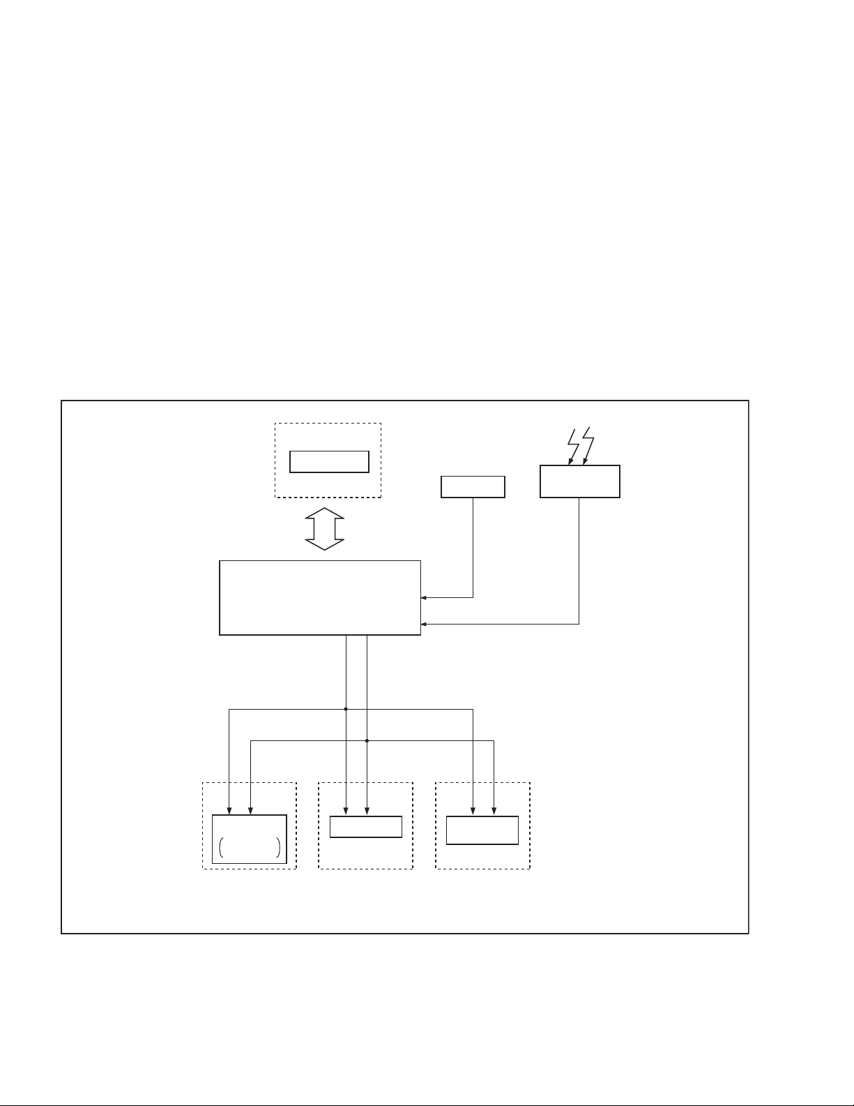
2.2 SYSTEM BLOCK DIAGRAM
TUNER
TUNER
CONTROL
MEMORY IC
SCL
CPU
(MAIN MICON)
SCL
MTS/TONE
SDA
SDA
AFC
DECODER
IF
1 Chip
REMOTE
CONTROL
1-4 (No.52111)
Page 5
2.3 MAIN DIFFERENCE LIST Parts Name AV-20420 AV-20421
BODY COLOR BLACK WHITE
FRONT CABINET LC10109-016A-A LC10109-017A-A
POWER KNOB LC30376-001A-A LC30376-002A-A
PUSH KNOB LC30271-001A-A LC30271-002A-A
REAR COVER LC10108-006A-A LC10108-007A-A
POWER CORD CLAMP LC20106-001D-A LC20106-002C-A
REMOTE CONTROL UNIT RM-C205-1C RM-C205W-1C
WHITE MARK (PACKING CASE) not used GQ40012-001A-A
AV-20420
AV-20421
(No.52111)1-5
Page 6

AV-20420
AV-20421
2.4 DISASSEMBLY PROCEDURE
2.4.1 REMOVING THE REAR COVER
(1) Unplug the power plug.
(2) Remove the 5 screws [A], and 2 screws [B] as shown in
Fig.1.
(3) Withdraw the REAR COVER toward you..
CAUTION:
When reinstalling the rear cover, carefully push it i nward after
inserting the MAIN PWB into the rear cover groove.
2.4.2 REMOVING THE MAIN PWB
• Remove the REAR COVER.
(1) Raise the backside of the MAIN PWB slig htly . And remove
the PWB STOPPER [C] from the cabinet bottom.
(2) Withdraw the MAIN PWB backward.
(If necessary, remove the wire clamp and connectors, etc.)
2.4.3 REMOVING THE SPEAKER
• Remove the MAIN PW board.
(1) Remove the 2 screws [D].
(2) Then you can remove the SPEAKER.
2.4.4 CHECKING THE MAIN PW BOARD
(1) Pull out the MAIN CHASSIS (refer to REMOVING THE
MAIN PWB).
(2) Erect the chassis vertically so that you can easily check the
MAIN PWB from the reverse (solder) side.
CAUTION:
• When erecting the MAIN PWB, be careful so that there will
be no contacting with other PWB.
• Before turning power on, make sure that the CRT earth wire
and other connectors are properly connected.
• When conducting a check with power supplied, be sure to
confirm that the CRT EARTH WIRE (BRAIDED ASS’Y) is
connected to the CRT SOCKET PWB.
2.4.5 WIRE CLAMPING AND CABLE TYING
(1) Be sure to clamp the wire.
(2) Never remove the cable tie used for tying the wires
together.
Should it be inadvertently removed, be sure to tie the wires
with a new cable tie.
1-6 (No.52111)
Page 7
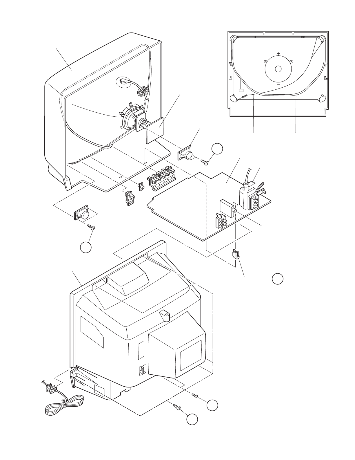
FRONT CABINET
AV-20420
AV-20421
CRT SOCKET PWB
(Within MAIN PWB)
SPEAKER
D
REAR COVER
D
MAIN PWB
PWB STOPPER
BRAIDED ASSY
HVT
TUNER
DEG. COIL
C
Fig.1
B
A
(No.52111)1-7
Page 8

AV-20420
AV-20421
2.5 REPLACEMENT OF MEMORY IC
2.5.1 MEMORY IC
This TV use memory IC.
In the memory IC, there are memorized data for correctly operating the video and deflection circuits.
When replacing the memory IC, be sure to use IC written with the initial values of data.
2.5.2 PROCEDURE FOR REPLACING MEMORY IC
(1) Power off
Switch the power off and unplug the power plug.
(2) Replace IC
Be sure to use a memory IC written with the initial setting data.
(3) Power on
Connect the power plug and switch the power on.
(4) Setting of receive channels
Set the receive channels. For setting, refer to the OPERATING INSTRUCTIONS.
(5) User settings
Check the user setting items according to TABLE “USER SETTING VALUE”, and if these are different, set the correct value.
(6) CHECK THE SYSTEM CONSTANT ITEMS
If the value of each item of a system setup is not correctly set
as a value peculiar to this television, operation of a
microcomputer and the output of an image do not become
suitable. Please set up the value of each item correctly,
according to the following description.
(1) Press the [SLEEP TIMER] key, and while the indication
of “SLEEP TIMER 0 MIN” is being displayed, press
[DISPLAY] key and [VIDEO STATUS] key on the remote
control unit simultaneously (Fig.1).
(2) The SERVICE MENU screen of Fig.1 will be displayed.
(3) While the SERVICE MENU is displayed, again
simultaneously press the [DISPLAY] and [VIDEO
STATUS] keys to display the SYSTEM CONSTANT
screen (Fig.2).
(4) Refer to the Table 1 of SYSTEM CONSTANT SETTING,
and check the setting items. Where these differ, select
the item with the [CH (-/+)] key and adjust it with the [VOL
(-/+)] keys (The letters of the selected item are displayed
in yellow).
(5) The setting value will be stored automatically when
release the remote control unit keys.
(6) Press the [EXIT] key twice to return to the normal screen.
SERVICE MENU
PICTURE SOUND
GAME
LOW LIGHT HIGH LIGHT
RF AFC CHK
VCO(CW)
SELECT BY EXIT BY
OPERATE BY
EXIT
Fig.1
SYSTEM CONSTANT
MODEL
V-CHIP
CAN V-CHIP
******** *****
SELECT BY EXIT BY
OPERATE BY
:
:
:
*******
YES
YES
EXIT
Fig.2
(7) SERVICE MENU setting
Verify what to set in the SERVICE MENU, and set whatever is necessary. Refer to the SECTION 3 ADJUSTMENT for setting.
1-8 (No.52111)
Page 9
2.5.3 SYSTEM CONSTANT SETTING
AV-20420
AV-20421
Setting Item
MODEL
V-CHIP
CAN V-CHIP
ޓAV-27220
ޓC-13210
Setting Content
AV-20220
C-20210
YES NO
YES NO
2.5.4 USER SETTING VALUE
Setting item Setting value
1. Use remote controller keys
POWER Off
CHANNEL CH 02
CHANNEL PRESET See OPERATING INSTRUCTIONS.
VOLUME 10
INPUT (TV/VIDEO) TV
DISPLAY Off
SLEEP TIMER 0
VIDEO STATUS STANDARD
2. Setting of MENU
TINT Center
COLOR Center
PICTURE Center
BRIGHT Center
DETAIL Center
BASS Center
TREBLE Center
BALANCE Center
MTS STEREO
TV SPEAKER ON
NOISE MUTING ON
SET VIDEO STATUS All center
SET CLOCK Unnecessary to set
ON/OFF TIMER OFF
LANGUAGE ENG
CLOSED CAPTION OFF
BACKGROUND BLACK
AUTO TUNER SETUP TUNER MODE : AIR
CHANNEL SUMMARY Unnecessary to set
V-CHIP OFF
SET LOCK CODE Unnecessary to set
AV-20420
AV-20220
YES
YES
/SA
AV-20421
AV-20220
YES
YES
/SA
(No.52111)1-9
Page 10
AV-20420
AV-20421
2.5.5 SERVICE MENU SETTING ITEM
Menu item Setting item Menu item Setting item
PICTURE 1. BRIGHT GAME TINT
2. PICTURE COLOR
3. TV DETAIL PICTURE
4. TV BPF BRIGHT
5. TINT DETAIL
6. COLOR LOW LIGHT RED
7. EXT BRIGHT GREEN
8. EXT PICTURE BLUE
9. EXT DETAIL HIGH LIGHT GREEN
10. EXT BPF BLUE
11. EXT TINT RF AFC CHECK
12. EXT COLOR FINE
13. V SIZE STATUS
14. V CENTER VCO(CW) Refer to “ADJUSTMENTS PROCEDURE”
15. H POSITION
16. OSD H POSITION
17. OSD V POSITION
18. H AFC
19. RF AGC
20. OSD SELECT
SOUND 1. IN LEVEL
2. FH MON
3. ST VCO
4. PILOT
5. FILTER
6. LOW SEP
7. HIGH SEP
8. 5FH MON
9. SAP VCO
10. FIL OFF
[Do not adjust]
RF AFC
1-10 (No.52111)
Page 11

2.6 REPLACEMENT OF CHIP COMPONENT
2.6.1 CAUTIONS
(1) Avoid heating for more than 3 seconds.
(2) Do not rub the electrodes and the resist parts of the pattern.
(3) When removing a chip part, melt the solder adequately.
(4) Do not reuse a chip part after removing it.
2.6.2 SOLDERING IRON
(1) Use a high insulation soldering iron with a thin pointed end of it.
(2) A 30w soldering iron is recommended for easily removing parts.
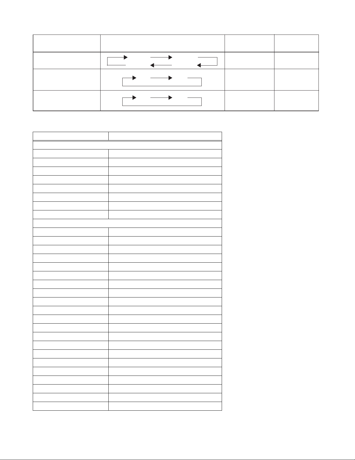
2.6.3 REPLACEMENT STEPS
1. How to remove Chip parts
[Resistors, capacitors, etc.]
(1) As shown in the figure, push the part with twe ezers and
alternately melt the solder at each end.
AV-20420
AV-20421
2. How to install Chip parts
[Resistors, capacitors, etc.]
(1) Apply solder to the pattern as indicated in the figure.
(2) Shift with the tweezers and remove the chip part.
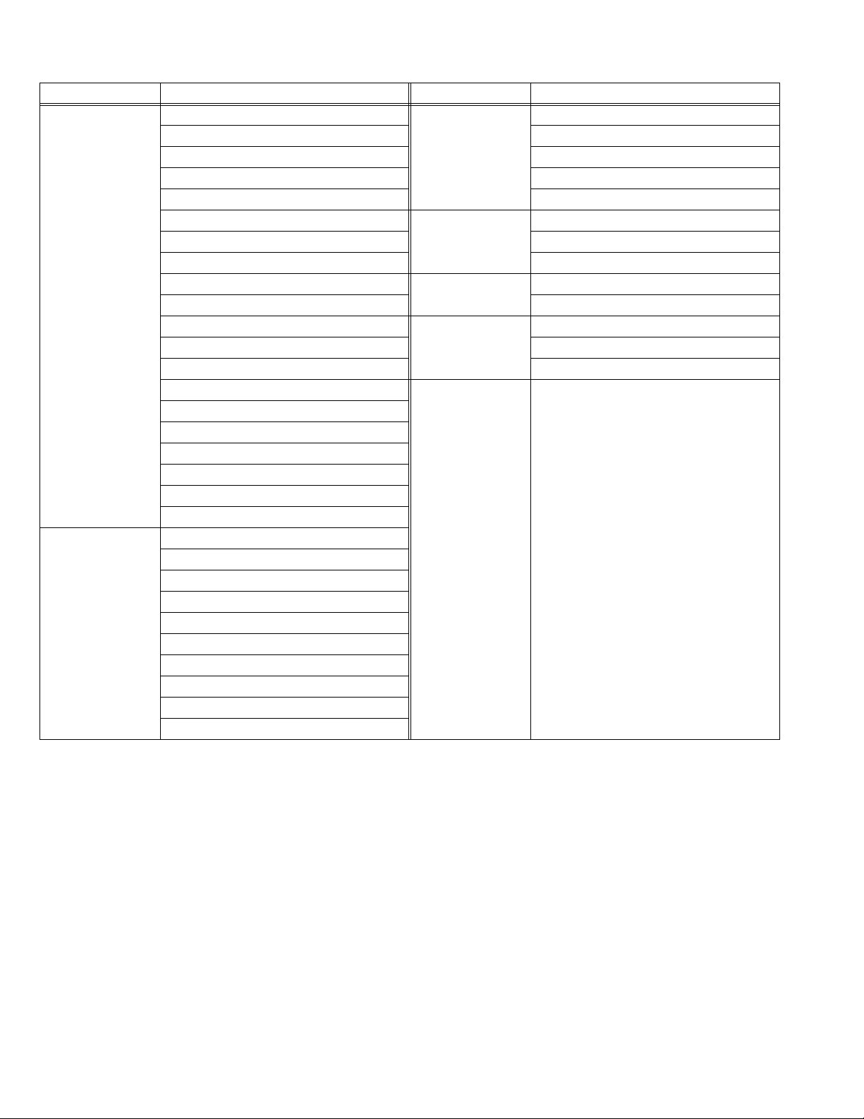
[Transistors, diodes, variable resistors, etc.]
(1) Apply extra solder to each lead.
SOLDER
SOLDER
(2) As shown in the figure, push the part with twe ezers and
alternately melt the solder at each lead. Shift and remove
the chip part.
(2) Grasp the chip part with tweezers and place it on the
solder. Then heat and melt the solder at both ends of the
chip part.
[Transistors, diodes, variable resistors, etc.]
(1) Apply solder to the pattern as indicated in the figure.
(2) Grasp the chip part with tweezers and place it on the
solder.
(3) First solder lead A as indicated in the figure.
A
B
C
Note :
After removing the part, remove remaining solder from the
pattern.
(4) Then solder leads B and C.
A
B
C
(No.52111)1-11
Page 12

AV-20420
AV-20421
SECTION 3
ADJUSTMENT
3.1 ADJUSTMENT PREPARATION
(1) There are 2 ways of adjusting this TV : One is with the REMOTE CONTROL UNIT and the other i s the conventional method
using adjustment parts and components.
(2) The adjustment using the REMOTE CONTROL UNIT is made on the basis of the initial setting values. The setting values which
adjust the screen to the optimum condition can be different from the initial setting values.
(3) Make sure that connection is correctly made AC to AC power source.
(4) Turn on the power of the TV and measuring instruments for warning up for at least 30 minutes before starting adjustments.
(5) If the receive or input signal is not specified, use the most appropriate signal for adjustment.
(6) Never touch the parts (such as variable resistors, transformers and condensers) not shown in the adjustment items of this service
adjustment.
(7) Preparation for adjustment. Unless otherwise specified in the adjustment items, preset the following functions with the REMOTE
CONTROL UNIT.
Setting item Setting value
VIDEO STATUS STANDARD
BASS/TREBLE/BALANCE Center
TINT / COLOUR / PICTURE / BRIGHT / DETAIL Center
MTS STEREO
3.2 MEASURING INSTRUMENT AND FIXTURES
• DC voltmeter (or digital voltmeter)
• Oscilloscope
• Frequency counter
• Signal generator (Pattern generator : NTSC)
• TV audio multiplex signal generator
• Remote control unit
3.3 ADJUSTMENT ITEMS
• B1 POWER SUPPLY VOLTAGE CHECK
• TUNER CIRCUIT / FOCUS
- IF VCO ADJUSTMENT
- RF AGC ADJUSTMENT
- FOCUS ADJUSTMENT
• DEFLECTION CIRCUIT
- V SIZE ADJUSTMENT
- H POSITION ADJUSTMENT
• WHITE BALANCE
- LOW LIGHT ADJUSTMENT
- HIGH LIGHT ADJUSTMENT
• VIDEO CIRCUIT
- SUB BRIGHT ADJUSTMENT
- SUB CONTRAST ADJUSTMENT
- SUB COLOR ADJUSTMENT
- SUB TINT ADJUSTMENT
• MTS CIRCUIT
- INPUT LEVEL ADJUSTMENT
- STEREO VCO ADJUSTMENT
- SAP VCO ADJUSTMENT
-FILTER CHECK
- SEPARATION ADJUSTMENT
• PURITY / CONVERGENCE
- PURITY ADJUSTMENT
- STATIC CONVERGENCE ADJUSTMENT
- DYNAMIC CONVERGENCE ADJUSTMENT
• HIGH VOLTAGE HOLD DOWN CIRCUIT CHECK
1-12 (No.52111)
Page 13

3.4 ADJUSTMENT LOCATIONS
AV-20420
AV-20421
CRT SOCKET PWB
(Within MAIN PWB ASS'Y)
TP-R
T
TP-E
(SOLDER SIDE)
(BRAIDED ASS'Y)
FRONT
MAIN PWB
REMOCON
POWER
RECEIVER
U
E1
CRT EARTH
FRONT
VOL+
CH-CH+VOL-
MENU
TP-91
(B1)
TP-E
( )
R926
PW
DEG.
F902
F901
IC921
ON
TIMER
TP-12B
CW
31
MPX
T131
CW
IC201
T
IC702IC701
TUNER
STEREO
S
IC421
U
HV
HVT
AV IN OUT
UPPER : FOCUS
LOWER : SCREEN
(No.52111)1-13
Page 14

AV-20420
AV-20421
3.5 BASIC OPERATION OF SERVICE MENU
3.5.1 TOOL OF SERVICE MENU OPERATION
Operate the SERVICE MENU with the REMOTE CONTROL UNIT.
3.5.2 SERVICE MENU ITEMS
With the SERVICE MENU, various adjustments can be made, and they are broadly classified in the following items of settings.
PICTURE This mode adjusts the VIDEO CHROMA and DEFLECTION control circuit.
SOUND This mode adjusts the SOUND control circuit.
GAME This mode adjusts the detailed GAME mode settings.
LOW LIGHT This mode adjusts the WHITE BALANCE (LOW LIGHT) control circuit.
HIGH LIGHT This mode adjusts the WHITE BALANCE (HIGH LIGHT) control circuit.
RF AFC CHECK This is no requirement for adjustment. Do not adjust this mode.
VCO(CW) This mode adjusts the VCO control circuit.
1-14 (No.52111)
Page 15

3.5.3 BASIC OPERATION IN SERVICE MENU
POWER
DISPLAY
INPUT
100+
RETURN+
MUTING
MENU
CHIP
EXIT
SLEEP
TIMER
VIDEO
STATUS
(1) HOW TO ENTER THE SERVICE MENU
Press the [SLEEP TIMER] key and set the SLEEP TIMER for
“0 MIN”.
Then press the [DISPLAY] key and [VIDEO STATUS] key of
the remote control unit at the same time to enter the SERVICE
MENU screen. The SERVICE MENU screen will be shown.
(2) SUB MENU SCREEN SELECTION
Press [CHANNEL (-/+)] keys of the REMOTE CONTROL
UNIT, and select the sub menu screen from SERVICE MENU.
In SERVICE MENU, press the [CHANNEL (-/+)] key to select
any of the sub menu items. The letters of the selected items
are displayed in yellow.
PICTURE SOUND
GAME
LOW LIGHT HIGH LIGHT
RF AFC CHK
VCO(CW)
[1]
Setting for 0 min
[2]
Simultaneously push
[3]
Select the item
SERVICE MENU
PICTURE SOUND
GAME
LOW LIGHT HIGH LIGHT
RF AFC CHK
VCO(CW)
SELECT BY EXIT BY
OPERATE BY
VIDEO
STATUS
DISPLAY
SLEEP
TIMER
1
4
7
100+
MUTING
CH
VOL
CH
MENU
EXIT
POWER
INPUT
2
5
8
RETURN+
0
V—CHIP
+
VOL
+
EXIT
3
6
9
[4]
Go into the item
Exit from
SERVICE MENU
AV-20420
AV-20421
(3) SETTING METHOD
[PICTURE AND SOUND ADJUSTMENT MODE]
(1) If select any of PICTURE or SOUND items, and the [VOLUME (-/+)] key is pressed from SERVICE MENU. The screen [2] will
be displayed as shown in figure page later.
(2) Then [CHANNEL (-/+)] key is pressed, the PICTURE mode screen [3] or the SOUND mode screen [4] will be displayed.
(3) Press the [CHANNEL (-/+)] keys to select the one of adjustment mode from 1. BRIGHT to 20. OSC SEL,
or from 1. IN LEVEL to 10. FIL OFF.
(4) Press the [VOLUME (-/+)] keys to change the adjustment value. The setting value will be stored auto mati cally whe n release
the REMOTE CONTROL UNIT keys.
It can adjust the items PICTURE and SOUND in the same procedure.
[GAME, LOW LIGHT AND HIGH LIGHT ADJUSTMENT MODE]
If select any of GAME, LOW LIGHT and HIGH LIGHT items, and the [VOLUME (-/+)] key is pressed from SERVICE MENU. The
screens [5], [6] or [7] will be displayed as shown in figure page later. Since the key operation in this mode is peculiar, please refer
to the clause of the “ADJUSTMENTS PROCEDURE”.
[RF AFC CHK ADJUSTMENT MODE]
This is no requirement for adjustment this mode. Don’t change these values.
[VCO(CW) ADJUSTMENT MODE]
Since the key operation and screen in this mode is peculiar, please refer to the clause of the “ADJUSTMENTS PROCEDURE”.
(4) RELEASE OF SERVICE MENU
When adjustment is completed, press the [EXIT] key twice. Then return to the normal screen.
(No.52111)1-15
Page 16

AV-20420
AV-20421
3.5.4 SERVICE SUB MENU
[1] SERVICE MENU (MAIN MENU)
SERVICE MENU
PICTURE
GAME
LOW LIGHT HIGH LIGHT
RF AFC CHK
VCO(CW)
SELECT BY
OPERATE BY
SOUND
EXIT BY
EXIT
[2] SCREEN
SELECT BY
OPERATE BY
[5] GAME MODE
TINT
COLOR
PICTURE
BRIGHT
DETAIL
SELECT BY
OPERATE BY
***
***
***
***
***
[6] LOW LIGHT MODE
EXIT BY
EXIT
EXIT BY
EXIT
[3] PICTURE MODE
1. BRIGHT
STATUS
SELECT BY
OPERATE BY
[4] SOUND MODE
1. IN LEVEL
STATUS
SELECT BY
OPERATE BY
***
********
EXIT BY
EXIT
***
********
EXIT BY
EXIT
BRIGHT
***
*** *** ***
BRIGHT
[7] HIGH LIGHT MODE
HIGH LIGHT
***
[8] RF AFC CHK MODE
[DO NOT ADJUST]
RF AFC
FINE
STATUS
SELECT BY
OPERATE BY
EXIT BY
EXIT
***
EXIT BY
EXIT
********
EXIT BY
EXIT
ON
***
1-16 (No.52111)
[9] VCO (CW) MODE
TOO HIGH
ABOVE REFERENCE
BELOW REFERENCE
TOO LOW
SYNC : YES
EXIT BY
EXIT
Page 17

AV-20420
AV-20421
3.6 INITIAL SETTING VALUE OF SERVICE MENU
(1) Adjustment of the SERVICE MENU is made on the basis of the initial setting values; however, the new setting values which set
the screen in its optimum condition may differ from the initial setting.
(2) Do not change the initial setting values of the setting (adjustment) items not listed in “ADJUSTMENTS PROCEDURE”.
3.6.1 PICTURE MODE
• The four setting items in the video mode No.7 EXT BRI., No.8 EXT PIC., No.11 EXT TINT and No.12 EXT COL. are linked to the
items in the TV MODE No.1 BRIGHT, No.2 PICTURE, No.5 TINT and No.6 COLOR, respectively. When the setting items in the TV
mode are adjusted, the values in the setting items in the video mode are revised automatically to the same values in the TV mo de
(The initial setting values given in ( ) are offset values).
• When the four items (No.7, 8, 11 and 12) are adjusted in the video mode, the setting values in each item are revised independently.
No. Setting item Variable range Initial setting value
1 BRIGHT 0 ~ 127 64
2 PICTURE 0 ~ 127 95
3 TV DTL(TV DETAIL) 0 ~ 63 26
4 TV BPF(TV B.P.FILTER) 0 / 1 0
5 TINT 0 ~ 127 70
6 COLOR 0 ~ 127 48
7 EXT BRI.(EXT.BRIGHT) ±25 (±0)
8 EXT PIC.(EXT.PICTURE) ±25 (±0)
9 EXT DTL(EXT.DETAIL) 0 ~ 63 26
10 EXT BPF(EXT.B.P.FILTER) 0 / 1 0
11 EXT TINT ±25 (+1)
12 EXT COL.(EXT.COLOR) ±25 (+3)
13 V SIZE 0 ~ 63 38
14 V CENT.(V.CENTER) 0 ~ 7 0
15 H POS.(H.POSITION) 0 ~ 31 20
16 OSD HP (OSD H POSITION) 0 ~ 31 26
17 OSD VP (OSD V POSITION) 0 ~ 15 14
18 H. AFC 0 / 1 0
19 RF AGC 0 ~ 63 40
20 OSC SEL 0 / 1 0
3.6.2 SOUND MODE
No. Setting item Variable range Initial setting value
1 IN LEVEL (INPUT LEVEL) 0 ~ 63 14
2 FH MON. (FM MONITOR) 0 / 1 0
3 ST VCO (STEREO VCO) 0 ~ 63 38
4 PILOT (PILOT CANCELER) 0 / 1 0
5 FILTER 0 ~ 63 35
6 LOW SEP. (LOW SEPARATION) 0 ~ 63 10
7 HI SEP. (HI SEPARATION) 0 ~ 63 9
8 5FH MON. (5FH MONITOR) 0 / 1 0
9 SAP VCO 0 ~ 63 40
10 FIL. OFF. ±10 0
(No.52111)1-17
Page 18

AV-20420
AV-20421
3.6.3 GAME MODE
No. Setting item Variable range Initial setting value
1TINT ±20 0
2COLOR ±20 0
3 PICTURE ±20 -10
4BRIGHT ±20 -5
5 DETAIL ±15 5
3.6.4 LOW LIGHT MODE
No. Setting item Variable range Initial setting value
1 R CUTOFF 0 ~ 255 20
2 G CUTOFF 0 ~ 255 20
3 B CUTOFF 0 ~ 255 20
3.6.5 HIGH LIGHT MODE
No. Setting item Variable range Initial setting value
1 G DRIVE 0 ~ 255 128
2 B DRIV E 0 ~ 255 128
3.6.6 RF AFC CHK MODE [DO NOT ADJUST]
No. Setting item Variable range Initial setting value
1 RF AFC ON / OFF ON
2 FINE -77 ~ +77 Display factory setting value
1-18 (No.52111)
Page 19

3.7 ADJUSTMENTS PROCEDURE
3.7.1 B1 POWER SUPPLY VOLTAGE CHECK
Item
B1 POWER
SUPPLY
Measuring
instrument
Test point Adjustment part Description
DC voltmeter TP-91 (B1)
TP-E
check
3.7.2 TUNER CIRCUIT / FOCUS
Item
Measuring
instrument
Test point Adjustment part Description
IF VCO Remote
control unit
TOO HIGH
ABOVE REFERENCE
BELOW REFERENCE
TOO LOW
SYNC : YES
[VCO(CW)]
CW transf. (T131)
YELLOW
AV-20420
AV-20421
(1) Receive the black-and-white signal.
(2) Connect the DC voltmeter to TP-91 (B1) and TP-E.
(3) Confirm that the voltage is DC134V.
Under normal conditions, no adjustment is required.
(1) Receive the NTSC broadcast (use channels without
offset frequency).
(2) Select the VCO(CW) mode from the SERVICE
MENU.
(3) Change [AFC] to OFF and [FINE] to 0.
(4) Confirm the color change (yellow) from [TOO HIGH]
to [TOO LOW] by CW transf., and [SYNC] is [YES]
being shown on the screen. Then, adjust CW transf.
until [BELOW REFERENCE] letters turns yellow and
confirm again [SYNC] is [YES].
(5) It returns the [AFC] to ON.
RF AGC Remote
control unit
Setting item
19. RF AGC
FOCUS Signal
generator
Remote
control unit
EXIT BY
EXIT
[PICTURE]
<19. RF AGC>
Initial setting value
40
FOCUS VR
[In HVT]
(1) Receive the broadcast.
(2) Select <19. RF AGC> of the PICTURE mode.
(3) Press the [MUTING] key and turn the color off.
(4) Get the noise in the screen with the [VOLUME (-)]
key (0 side of setting value).
(5) Press the [VOLUME (+)] key, and stop when noise
disappears in the screen.
(6) Change to other channels and make sure that there
is no irregularity.
(7) Press the [MUTING] key and get the color.
(1) Receive the crosshatch signal.
(2) While looking at the screen, adjust FOCUS VR so
that the vertical and horizontal lines will be clear and
in fine detail.
(3) Make sure that the picture is in focus even when the
screen gets darkened.
(No.52111)1-19
Page 20

AV-20420
AV-20421
3.7.3 DEFLECTION CIRCUIT
Item
V. SIZE Signal
generator
Remote
control unit
Measuring
instrument
Test point Adjustment part Description
[PICTURE]
<13. V SIZE>
(1) Receive the crosshatch signal.
(2) Select <13. V SIZE> of the PICTURE mode.
(3) Set the initial setting value of <13 V SIZE>.
(4) Adjust <13. V SIZE> until the vertical screen size is
92%.
Screen
size
92%
Setting item
13. V SIZE
H. POSITION Signal
generator
Remote
control unit
Setting item
Initial setting value
38
[PICTURE]
<15. H POS>
Initial setting value
Picture
size
100%
(1) Receive the crosshatch signal.
(2) Select the <15. H POS> of the PICTURE mode.
(3) Set the initial setting value of the <15 H POS>.
(4) Adjust the <15. H POS> until the screen will be
horizontally centered.
1-20 (No.52111)
15. H POS
20
Page 21

3.7.4 WHITE BALANCE
100+
RETURN+
Item
WHITE
BALANCE
Measuring
instrument
Signal
generator
(Low Light)
Remote
control unit
R CUTOFF
BRIGHT
BRIGHT
***
Test point Adjustment part Description
[PICTURE]
<1. BRIGHT>
(1) Receive the black-and-white signal (color off).
(2) Select <1. BRIGHT> of the PICTURE mode.
(3) Set the initial setting value of the <1 BRIGHT>.
[LOW LIGHT]
<R CUTOFF>
<G CUTOFF>
<B CUTOFF>
(4) Select the [LOW LIGHT] mode from SERVICE
MENU.
(5) Set the initial setting value of <R CUTOFF>, <G
CUTOFF> and <B CUTOFF> with from [4] to [9]
keys.
SCREEN VR
[In HVT]
(6) Show the single horizontal line by pressing the [1]
key.
(7) Turn the SCREEN VR all the way to the left.
(8) Turn the SCREEN VR gradually to the right from the
left until either one of the red, blue or green colors
appears faintly.
(9) Adjust the two colors which did not appear until the
BRIGHT
G CUTOFF
B CUTOFF
single horizontal line that is displayed becomes
***
***
***
EXIT BY
EXIT
white using the [4] to [9] keys.
(10) Turn the SCREEN VR to where the single horizontal
line glows faintly.
(11) Press the [2] key to return to the regular screen.
(12) Press the [3] key to exit from the WHITE BALANCE
mode.
AV-20420
AV-20421
H LINE OFF
H LINE ON
R CUTOFF
R CUTOFF
1
4
7
100+
Setting item
R CUTOFF
G CUTOFF 20
B CUTOFF 20
2
5
8
3
6
9
RETURN+
Initial setting value
20
G CUTOFF
EXIT
B CUTOFF
B CUTOFF
G CUTOFF
(No.52111)1-21
Page 22

AV-20420
100+
RETURN+
AV-20421
Item
WHITE
BALANCE
(High Light)
G DRIVE
G DRIVE
Measuring
instrument
Test point Adjustment part Description
Signal
generator
Remote
control unit
G DRIVE B DRIVE
HIGH LIGHT
***
1
4
7
100+
2
5
8
***
EXIT BY
3
6
9
RETURN+
[HIGH LIGHT]
<G DRIVE>
<B DRIVE>
EXIT
(1) Receive the black-and-white signal (color off).
(2) Select the HIGH LIGHT mode of the SERVICE
MENU.
(3) Set the initial setting value of <G DRIVE> and <B
DRIVE> with the [5], [6], [8] and [9] keys.
(4) Adjust the screen until it becomes white using the
[5], [6], [8] and [9] keys.
(5) Press the [3] key to exit from the WHITE BALANCE
mode.
EXIT
B DRIVE
B DRIVE
Setting item
G DRIVE
B DRIVE 128
3.7.5 VIDEO CIRCUIT
Item
SUB
BRIGHT
Measuring
instrument
Remote
control unit
Setting item
1. BRIGHT
Initial setting value
128
Test point Adjustment part Description
[PICTURE]
<1. BRIGHT>
(1) Receive the broadcast.
(2) Select <1. BRIGHT> of the PICTURE mode.
(3) Set the initial setting value of the <1 BRIGHT>.
(4) If the brightness is not best with the initial setting
value, make fine adjustment of the <1 BRIGHT> until
you get the optimum brightness.
Initial setting value
64
1-22 (No.52111)
Page 23

AV-20420
AV-20421
Item
SUB
CONTRAST
Measuring
instrument
Remote
control unit
Setting item
2. PICTURE
SUB COLOR Signal
generator
Oscilloscope
Remote
control unit
Setting item
6. COLOR
Test point Adjustment part Description
[PICTURE]
<2. PICTURE>
(1) Receive the broadcast.
(2) Select <2. PICTURE> of the PICTURE mode.
(3) Set the initial setting value of the <2. PICTURE>.
(4) If the contrast is not best with the initial setting value,
make fine adjustment of the <2. PICTURE> until you
get the optimum contrast.
Initial setting value
95
TP-R
TP-E
[CRT SOCKET
PWB]
[PICTURE]
<6. COLOR>
[ Method of adjustment without measuring instrument ]
(1) Receive the broadcast.
(2) Select <6. COLOR> of the PICTURE mode.
(3) Set the initial setting value of the <6. COLOR>.
(4) If the color is not best with the initial setting value,
make fine adjustment of the <6. COLOR> until you
get the optimum color.
[ Method of adjustment using measuring instrument ]
(1) Receive the full field color bar signal (75% white).
Initial setting value
(2) Select <6. COLOR> of the PICTURE mode.
(3) Set the initial setting value of the <6. COLOR>.
(4) Connect the oscilloscope between TP-R and TP-E.
48
(5) Adjust <6. COLOR> and bring the value of (A) in the
illustration to +16V.
CG
W
YMR
(75%)
B
(-)
0V
(A)
V(W-R)
(+)
(No.52111)1-23
Page 24

AV-20420
AV-20421
Item
Measuring
instrument
SUB TINT Signal
generator
Oscilloscope
Remote
control unit
Setting item
5. TINT
Test point Adjustment part Description
TP-R
TP-E
[CRT SOCKET
PWB]
[PICTURE]
<5. TINT>
[ Method of adjustment without measuring instrument ]
(1) Receive the broadcast.
(2) Select <5. TINT> of the PICTURE mode.
(3) Set the initial setting value of the <5. TINT>.
(4) If the tint is not best with the initial setting value,
make fine adjustment of the <5. TINT> until you get
the optimum color.
[ Method of adjustment using measuring instrument ]
(1) Receive the full field color bar signal (75% white).
Initial setting value
(2) Select <5. TINT> of the PICTURE mode.
(3) Set the initial setting value of the <5. TINT>.
(4) Connect the oscilloscope between TP-R and TP-E.
70
(5) Adjust <5. TINT> and bring the value of (A) in the
illustration to +13V.
B
CG
3.7.6 MTS CIRCUIT
Item
MTS INPUT
LEVEL
instrument
Remote
control unit
Setting item
1. IN LEVEL
W
YMR
(75%)
Measuring
(-)
V(W-Y)
0V
(+)
(B)
Test point Adjustment part Description
[SOUND]
<1. IN LEVEL>
(1) Select the <1. IN LEVEL> of the SOUND mode.
(2) Verify that the <1. IN LEVEL> is set at its initial
setting value.
Initial setting value
14
1-24 (No.52111)
Page 25

AV-20420
AV-20421
Item
MTS
STEREO VCO
MTS SAP
VCO
Measuring
instrument
Signal
generator
Test point Adjustment part Description
R OUT
[AUDIO OUT]
Frequency
counter
Remote
control unit
Setting item
2. FH MON
3. ST VCO 38
Signal
generator
Initial setting value
MPX
Connector
4pin SDA
Frequency
3pin GND
counter
R OUT
Remote
[AUDIO OUT]
control unit
Resistor
[1M ohm]
Setting item
Initial setting value
[SOUND]
<2. FH MON>
<3. ST VCO>
0
[SOUND]
<8. 5FH MON>
<9. SAP VCO>
(1) Receive the RF signal (no modulated sound signal)
from the antenna terminal.
(2) Select the <2. FH MON> of SOUND mode, and
change the setting value from 0 to 1.
(3) Connect the frequency counter to R OUT of the
AUDIO OUT.
(4) Select the <3. ST VCO>.
(5) Set the initial setting value of the <3. ST VCO>.
(6) Adjust the <3. ST VCO> so that the frequency
counter will display 15.73kHz
±0.1kHz.
(7) Select the <2. FH MON> of the SOUND mode, and
reset the setting value from 1 to 0.
(1) Receive the RF signal (non modulated sound signal)
from the antenna terminal.
(2) Connect the 1M ohm resistor between the pin [4] and
pin [3] of MPX connector.
(3) Select the <8. 5FH MON> of the SOUND mode, and
reset the setting value from 0 to 1.
(4) Connect the frequency counter to R out of the
AUDIO OUT.
(5) Select the <9. SAP VCO>.
(6) Set the initial setting value of <9 SAP VCO>.
(7) Adjust the <9. SAP VCO> so that the frequency
counter will display 78.67kHz
±0.5kHz.
(8) Select the <8. 5FH MON> of the SOUND mode, and
reset the setting value from 1 to 0.
MTS FILTER
check
8. 5FH MON
9. SAP VCO 40
Remote
control unit
Setting item
5. FILTER
Initial setting value
0
[SOUND]
<5. FILTER>
35
(1) Select the <5. FILTER> of the SOUND mode.
(2) Verify that the <5. FILTER> is set at its initial setting
value.
(No.52111)1-25
Page 26

AV-20420
AV-20421
Item
MTS
SEPARATION
1 cycle
Measuring
instrument
TV audio
multiplex
signal
generator
Oscilloscope
Remote
control unit
L-Channel
signal waveform
Test point Adjustment part Description
L OUT
R OUT
[AUDIO OUT]
[SOUND]
<6. LOW SEP>
<7. HI SEP>
(1) Input a stereo L signal (300Hz) from the TV audio
multiplex signal generator to the antenna terminal.
(2) Connect an oscilloscope to L OUT of the AUDIO
OUT, and display one cycle portion of the 300Hz
signal.
(3) Change the connection of the oscilloscope to R OUT
of the AUDIO OUT, and enlarge the voltage axis.
(4) Select the <6. LOW SEP> of the SOUND mode.
(5) Set the initial setting value of the <6. LOW SEP>.
(6) Adjust the <6. LOW SEP> so that the wave element
of the 300Hz signal will become minimum.
(7) Change the signal to 3kHz, and similarly adjust the
<7. HI SEP>.
R-Channel
crosstalk portion
Minimum
Setting item
6. LOW SEP
7. HI SEP 9
Initial setting value
10
1-26 (No.52111)
Page 27

3.7.7 PURITY AND CONVERGENCE
PURITY ADJUSTMENT
(1) Demagnetize CRT with the demagnetizer.
(2) Loosen the retainer screw of the deflection yoke.
(3) Remove the wedges.
(4) Input a green raster signal from the signal generator, and
turn the screen to green raster.
(5) Move the deflection yoke backward.
(6) Bring the long lug of the purity magnets on the short lug and
position them horizontally. (Fig.2)
WEDGE
CRT
P/C MAGNETS
P : PURITY MAGNET
4 : 4 POLES (convergence magnets)
6 : 6 POLES (convergence magnets)
DEFLECTION
YOKE
㪧
㪋㪍
P / C
MAGNETS
Fig.1
AV-20420
AV-20421
(7) Adjust the gap between two lugs so that the GREEN
RASTER will come into the center of the screen. (Fig.3)
(8) Move the deflection yoke forward, and fix the position of the
deflection yoke so that the whole screen will become green.
(9) Insert the wedge to the top side of the deflection yoke so that
it will not move.
(10) Input a crosshatch signal.
(11) Verify that the screen is horizontal.
(12) Input red and blue raster signals, and make sure that purity
is properly adjusted.
Long lug
Short lug
(FRONT VIEW)
PURITY MAGNETS
Bring the long lug over the short lug
and position them horizontally.
Fig.2
GREEN RASTER
CENTER
Fig.3
(No.52111)1-27
Page 28

AV-20420
AV-20421
STATIC CONVERGENCE ADJUSTMENT
(1) Input a crosshatch signal.
(2) Using 4-pole convergence magnets, overlap the red and
blue lines in the center of the screen (Fig.1) and turn them
to magenta (red/blue).
(3) Using 6-pole convergence magnets, overlap the magenta
(red/blue) and green lines in the center of the scre en and
turn them to white.
(4) Repeat 2 and 3 above, and make best convergence.
(FRONT VIEW)
Fig.1
DYNAMIC CONVERGENCE ADJUSTMENT
(1) Move the deflection yoke up and down and overlap the lines
in the periphery. (Fig. 2)
(2) Move the deflection yoke left to right and overlap the lines in
the periphery. (Fig. 3)
(3) Repeat 1 and 2 above, and make best convergence.
• After adjustment, fix the wedge at the original position. Fasten
the retainer screw of the deflection yoke. Fix the 6 magnets with
glue.
(FRONT VIEW)
BLUE
GREEN
RED
(FRONT VIEW)
GREEN
RED
RED
BLUE
BLUE
GREEN
GREEN RED
BLUE
Fig.2
BLUE
GREEN
RED
RED
GREEN
BLUE
RED
GREEN
BLUE
1-28 (No.52111)
Fig.3
BLUE
GREEN
RED
Page 29

3.7.8 HOW TO CHECK THE HIGH VOLTAGE HOLD DOWN CIRCUIT
3.7.8.1 HIGH VOLTAGE HOLD DOWN CIRCUIT
After repairing the high voltage hold down circuit shown in Fig.1.
This circuit shall be checked to operate correctly.
3.7.8.2 CHECKING OF THE HIGH VOLTAGE HOLD DOWN CIRCUIT
(1) Turn the power switch to on.
(2) As shown in Fig. 1, set the resistor between [X] connector [1] and [3].
(3) Make sure that the screen picture disappears.
(4) Temporarily unplug the power plug.
(5) Remove the resistor replaced [X] connector [1] and [3].
(6) Again plug the power plug, make sure that the normal picture is displayed on the screen.
RY901
RESISTOR
16.7k 1% 1/4W
Q951
R953
D958
CONNECTOR
POWER
ON OFF
3 2 1
Q562
X
AV-20420
AV-20421
HEATER
T522
D563
Q561
R564
C562
D562
R563
Fig.1
R562
C561
D561
R561
4
D565
BW
(No.52111)1-29
Page 30

AV-20420
AV-20421
SECTION 4
TROUBLE SHOOTING
4.1 SELF CHECK FUNCTIONS
4.1.1 OUTLINE
This model has self check functions given below. When a malfuncti on has been detected, the POWER is turned off and the LED
flashes to inform of the failure . The malfunction is detected by the signal input state of the control line connected to the microcomputer.
4.1.2 SELF CHECK ITEMS
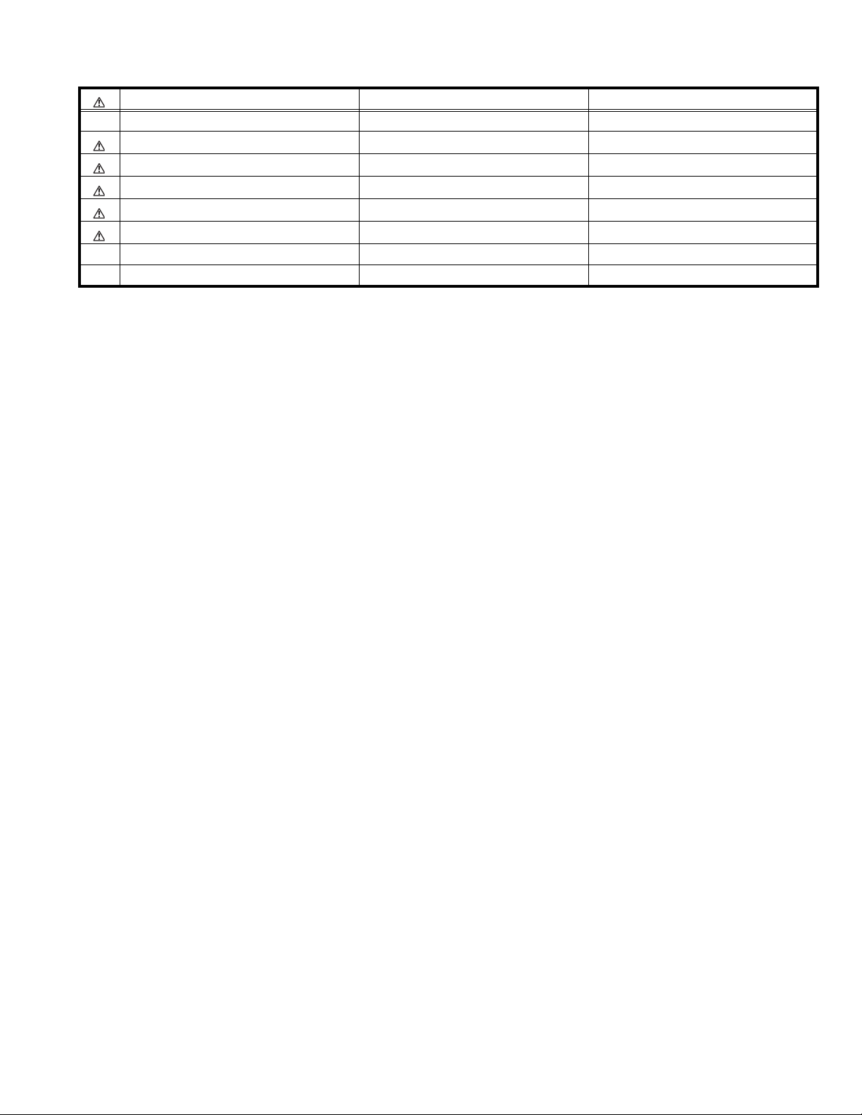
Check item Details of detection Method of detection State of malfunction
CRT NECK protector
[Also detected if the power
supply line output from the HVT
(High voltage Transformer) has
shorted with the ground.]
When the vertical circuit Scorrection capacitor C427 is
shorted, detect the potential
drop of the C427, and prevent
the burn damage to the CRT
NECK.
(Shorting of the power supply
output from the HVT to the
vertical circuit, and the small
signal power supply is also
detected.)
The microcomputer detects at
1 second intervals.
If NG is detected for more than
1 ms, a malfunction is
interpreted.
When a malfunction has been
detected, the POWER is turned
off. While the POWER is being
turned off , the power key of the
remote controller is not
operational until the power code
is taken out and put in again.
4.1.3 SELF CHECK INDICATING FUNCTION
The self-check function begins detection about 5 seconds after
power is supplied.
In the event a malfunction is detected, the power is cut off
immediately.
At this time, the ON-TIMER LED flashes to inform of the
malfunction.
[ON-TIMER LED indication]
The ON-TIMER LED flashes at 0.5 seconds intervals.
POWER
Supplied
After about
5 seconds
Malfunction
is detected
POWER OFF
Flashing
ON-TIMER LED
1-30 (No.52111)
Page 31

AV-20420
AV-20421
(No.52111)1-31
Page 32

AV-20420
AV-20421
JVC SERVICE & ENGINEERING COMPANY OF AMERICA
DIVISION OF JVC AMERICAS CORP.
www.jvcservice.com(US Only)
JVC CANADA INC.
Head office : 21 Finchdene Square Scarborough, Ontario M1X 1A7 (416)293-1311
(No.52111)
Printed in Japan
200303WPC
 Loading...